

Ruckus Wireless MediaFlex MF7211, MediaFlex MF7211-EXT, MediaFlex MF7211-Outdoor User Manual

Ruckus Wireless™
MediaFlex
™
7211
Smart Wi-Fi Gateway
User Guide
For the following MediaFlex 7211 Smart Wi-Fi Gateway models:
■ 7211 Smart Wi-Fi Gateway (MF7211)
■ 7211 EXT Smart Wi-Fi Gateway (MF7211-EXT)
■ 7211 Outdoor Smart Wi-Fi Gateway (MF7211-Outdoor)
Part Number 800-70273-001 Rev B
Published September 2010
www.ruckuswireless.com


i
About This Guide
Document Conventions . . . . . . . . . . . . . . . . . . . . . . . . . . . . . . . . . . . . . . . . . . . . . . . . . i
Related Documentation . . . . . . . . . . . . . . . . . . . . . . . . . . . . . . . . . . . . . . . . . . . . . . . . .ii
Documentation Feedback . . . . . . . . . . . . . . . . . . . . . . . . . . . . . . . . . . . . . . . . . . . . . . .ii
1
Introducing the 7211 Smart Wi-Fi Gateway
Overview of the 7211 Smart Wi-Fi Gateway . . . . . . . . . . . . . . . . . . . . . . . . . . . . . . . . .2
Unpacking the Smart Wi-Fi Gateway . . . . . . . . . . . . . . . . . . . . . . . . . . . . . . . . . . . . . . .2
Package Contents . . . . . . . . . . . . . . . . . . . . . . . . . . . . . . . . . . . . . . . . . . . . . . . . . . . 2
Getting to Know the Smart Wi-Fi Gateway Features . . . . . . . . . . . . . . . . . . . . . . . . . .3
MF7211 and MF7211-EXT Models . . . . . . . . . . . . . . . . . . . . . . . . . . . . . . . . . . . . . . 3
MF7211-Outdoor Model . . . . . . . . . . . . . . . . . . . . . . . . . . . . . . . . . . . . . . . . . . . . . . 7
2
Installing the Smart Wi-Fi Gateway
Installing the MF7211/MF7211-EXT Model . . . . . . . . . . . . . . . . . . . . . . . . . . . . . . . . .12
Step 1: Prepare the Administrative Computer . . . . . . . . . . . . . . . . . . . . . . . . . . . 12
Step 2: Connect the Device to a Power Source and the Admin Computer . . . . 12
Step 3: Configure the Device Using the Quick Start Wizard . . . . . . . . . . . . . . . . 13
Step 4: Verify That Your Computer Can Connect to the Internet . . . . . . . . . . . . 16
What to Do Next . . . . . . . . . . . . . . . . . . . . . . . . . . . . . . . . . . . . . . . . . . . . . . . . . . . 17
Installing the MF7211-Outdoor Model. . . . . . . . . . . . . . . . . . . . . . . . . . . . . . . . . . . . .18
Step 1: Prepare the Administrative Computer . . . . . . . . . . . . . . . . . . . . . . . . . . . 18
Step 2: Connect the Device to a Power Source and the Admin Computer . . . . 19
Step 3: Configure the Device Using the Quick Setup Wizard . . . . . . . . . . . . . . . 20
Step 4: Verify That the Device Can Connect to the Internet . . . . . . . . . . . . . . . . 22
If You Are Mounting the Device Outdoors . . . . . . . . . . . . . . . . . . . . . . . . . . . . . . 23
What to Do Next . . . . . . . . . . . . . . . . . . . . . . . . . . . . . . . . . . . . . . . . . . . . . . . . . . . 24
3
Navigating the Web Interface
Logging Into the Web Interface . . . . . . . . . . . . . . . . . . . . . . . . . . . . . . . . . . . . . . . . . .26
Contents

ii
Navigating the Web Interface. . . . . . . . . . . . . . . . . . . . . . . . . . . . . . . . . . . . . . . . . . . .28
4
Configuring the Smart Wi-Fi Gateway
Configuring Device Settings . . . . . . . . . . . . . . . . . . . . . . . . . . . . . . . . . . . . . . . . . . . . .32
Configuring Internet Settings . . . . . . . . . . . . . . . . . . . . . . . . . . . . . . . . . . . . . . . . . . . .33
Default IP Addressing Behavior . . . . . . . . . . . . . . . . . . . . . . . . . . . . . . . . . . . . . . . 33
Obtaining and Assigning an IP Address . . . . . . . . . . . . . . . . . . . . . . . . . . . . . . . . 33
Changing the Network Connection Type . . . . . . . . . . . . . . . . . . . . . . . . . . . . . . . 35
Renewing and Releasing DHCP . . . . . . . . . . . . . . . . . . . . . . . . . . . . . . . . . . . . . . . 35
Configuring System Settings. . . . . . . . . . . . . . . . . . . . . . . . . . . . . . . . . . . . . . . . . . . . .36
Configuring Wireless Settings. . . . . . . . . . . . . . . . . . . . . . . . . . . . . . . . . . . . . . . . . . . .39
Configuring Common Wireless Settings . . . . . . . . . . . . . . . . . . . . . . . . . . . . . . . . 39
Configuring WAN Settings . . . . . . . . . . . . . . . . . . . . . . . . . . . . . . . . . . . . . . . . . . . 43
Configuring Wireless # Settings . . . . . . . . . . . . . . . . . . . . . . . . . . . . . . . . . . . . . . . 45
Configuring Port Forwarding . . . . . . . . . . . . . . . . . . . . . . . . . . . . . . . . . . . . . . . . . . . .52
Controlling Access to the Wireless Network . . . . . . . . . . . . . . . . . . . . . . . . . . . . . . . .55
Access Control Options . . . . . . . . . . . . . . . . . . . . . . . . . . . . . . . . . . . . . . . . . . . . . . 55
Changing the Access Controls for a WLAN . . . . . . . . . . . . . . . . . . . . . . . . . . . . . . 56
Removing a MAC Address . . . . . . . . . . . . . . . . . . . . . . . . . . . . . . . . . . . . . . . . . . . 57
Running the Smart Configuration Wizard . . . . . . . . . . . . . . . . . . . . . . . . . . . . . . . . . .57
5
Managing the Smart Wi-Fi Gateway
Viewing Current Wireless Settings . . . . . . . . . . . . . . . . . . . . . . . . . . . . . . . . . . . . . . . .64
Changing the Administrative Login Settings. . . . . . . . . . . . . . . . . . . . . . . . . . . . . . . .65
Configuring Management Access Options . . . . . . . . . . . . . . . . . . . . . . . . . . . . . . . . .67
Enabling Logging and Sending Event Logs to a Syslog Server. . . . . . . . . . . . . . . . .69
Sending a Copy of the Log File to Ruckus Wireless Support. . . . . . . . . . . . . . . . . . .70
Saving a Copy of the Current Log to Your Computer . . . . . . . . . . . . . . . . . . . . . 70
Upgrading the Firmware . . . . . . . . . . . . . . . . . . . . . . . . . . . . . . . . . . . . . . . . . . . . . . . .71
Upgrading Manually via the Web . . . . . . . . . . . . . . . . . . . . . . . . . . . . . . . . . . . . . . 72
Upgrading Manually via FTP or TFTP . . . . . . . . . . . . . . . . . . . . . . . . . . . . . . . . . . . 72
Upgrading from a Local Computer . . . . . . . . . . . . . . . . . . . . . . . . . . . . . . . . . . . . 72
Configuring Automatic Upgrade . . . . . . . . . . . . . . . . . . . . . . . . . . . . . . . . . . . . . . 73
Rebooting the Smart Wi-Fi Gateway . . . . . . . . . . . . . . . . . . . . . . . . . . . . . . . . . . . . . .75
Resetting to Factory Default . . . . . . . . . . . . . . . . . . . . . . . . . . . . . . . . . . . . . . . . . . . . .76

iii
Running Diagnostics . . . . . . . . . . . . . . . . . . . . . . . . . . . . . . . . . . . . . . . . . . . . . . . . . . .76
Where to Find More Information . . . . . . . . . . . . . . . . . . . . . . . . . . . . . . . . . . . . . . . . .78
Index

iv
i
About This Guide
Document Conventions
About This Guide
This guide describes how to install, configure, and manage the Ruckus Wireless™
MediaFlex
™
7211 Smart Wi-Fi Gateway. This guide is written for those responsible for
installing and managing network equipment. Consequently, it assumes that the reader
has basic working knowledge of local area networking, wireless networking, and
wireless devices.
NOTE: If release notes are shipped with your product and the information there
differs from the information in this guide, follow the instructions in the release notes.
Most user guides and release notes are available in Adobe Acrobat Reader Portable
Document Format (PDF) or HTML on the Ruckus Wireless Support Web site at:
http://support.ruckuswireless.com/
Document Conventions
Ta bl e 1 and Tab le 2 list the text and notice conventions that are used throughout this
guide.
Tab le 1 . Tex t C o nv en t i o ns
Convention Description Example
monospace
Represents information as it
appears on screen
[Device name]>
monospace bold
Represents information that
you enter
[Device name]> set
ipaddr 10.0.0.12
default font bold
Keyboard keys, software
buttons, and field names
On the Start menu, click All
Programs.
italics
Screen or page names Click Advanced Settings.
The Advanced Settings page
appears.

ii
About This Guide
Related Documentation
Related Documentation
In addition to this User Guide, each Ruckus Wireless 7211 Smart Wi-Fi Gateway
documentation set includes the following:
■ Quick Setup Guide/Getting Started Guide: Provides essential installation and
configuration information to help you get the Smart Wi-Fi Gateway up and running
within minutes.
■ Online Help: Provides instructions for performing tasks using the Smart Wi-Fi
Gateway’s Web interface. The online help is accessible from the Web interface
and is searchable.
■ Release Notes: Provide information about the current software release, including
new features, enhancements, and known issues.
Documentation Feedback
Ruckus Wireless is interested in improving its documentation and welcomes your
comments and suggestions. You can email your comments to Ruckus Wireless at:
docs@ruckuswireless.com
When contacting us, please include the following information:
■ Document title
■ Document part number (on the cover page)
■ Page number (if appropriate)
For example:
■ Ruckus Wireless MediaFlex 7211 Smart Wi-Fi Gateway User Guide
■ Part number: 800-70273-001
■ Page 88
Table 2. Notice Conventions
Icon Notice Type Description
Information Information that describes
important features or
instructions
Caution Information that alerts you to
potential loss of data or
potential damage to an
application, system, or device
Warning Information that alerts you to
potential personal injury

1
1
Introducing the 7211 Smart Wi-Fi
Gateway
In This Chapter
Overview of the 7211 Smart Wi-Fi Gateway
. . . . . . . . . . . . . . . . . . . . . . . . . . . . . .2
Unpacking the Smart Wi-Fi Gateway . . . . . . . . . . . . . . . . . . . . . . . . . . . . . . . . . . . .2
Getting to Know the Smart Wi-Fi Gateway Features
. . . . . . . . . . . . . . . . . . . . . . .3

2
Introducing the 7211 Smart Wi-Fi Gateway
Overview of the 7211 Smart Wi-Fi Gateway
Overview of the 7211 Smart Wi-Fi Gateway
Congratulations on your purchase of the Ruckus Wireless MediaFlex 7211 Smart
Wi-Fi Gateway!
The 7211 Smart Wi-Fi Gateway is a purpose-built home gateway designed to deliver
the best possible connectivity from Wireless Broadband Networks to subscriber
homes. Wireless Broadband Networks provide coverage across wide areas using a
mesh distribution of access points based on standard Wi-Fi protocols.
The installation uses outdoor high power wireless mesh routers to achieve coverage
for outdoor wireless devices. Typically, the indoor coverage is inadequate to maintain
an acceptable quality level for users within the home.
The 7211 Smart Wi-Fi Gateway allows the extension of the Wireless Broadband
Network signals to achieve a robust coverage within home. The Smart Wi-Fi Gateway
communicates with the mesh network routers to allow home devices (such as personal
computers or laptop computers) to access the Internet.
Unpacking the Smart Wi-Fi Gateway
1. Open the Smart Wi-Fi Gateway package, and then carefully remove the contents.
2. Return all packing materials to the shipping box, and put the box away in a dry
location.
3. Verify that all items listed in Package Contents
below are included in the package.
Check each item for damage. If any item is damaged or missing, notify your
authorized Ruckus Wireless sales representative.
Package Contents
The contents of your Smart Wi-Fi Gateway package depend on the model. Refer to
the sections below for more details.
MF7211 and MF7211-EXT
■ MF7211-Indoor or MF7211-EXT unit
■ Power adapter
■ One CAT5 Ethernet cable
■ A packet that contains the side cover and two screws
■ Software License Agreement/Product Warranty Statement
■ Quick Setup Guide
MF7211-Outdoor
■ MF7211-Outdoor unit
■ Ruckus Wireless PoE injector

3
Introducing the 7211 Smart Wi-Fi Gateway
Getting to Know the Smart Wi-Fi Gateway Features
■ Power adapter for the PoE injector
■ A packet that contains the side cover, two screws, and two silicone screw caps
■ Software License Agreement/Product Warranty Statement
■ Quick Setup Guide
Getting to Know the Smart Wi-Fi Gateway
Features
This section identifies the physical features of each Smart Wi-Fi Gateway model that
is discussed in this guide. Before you begin the installation process, Ruckus Wireless
recommends that you become familiar with these features.
■ MF7211 and MF7211-EXT Models
■ MF7211-Outdoor Model
MF7211 and MF7211-EXT Models
This section describes the physical features of the MF7211 and MF211-EXT models.
Front Panel Features
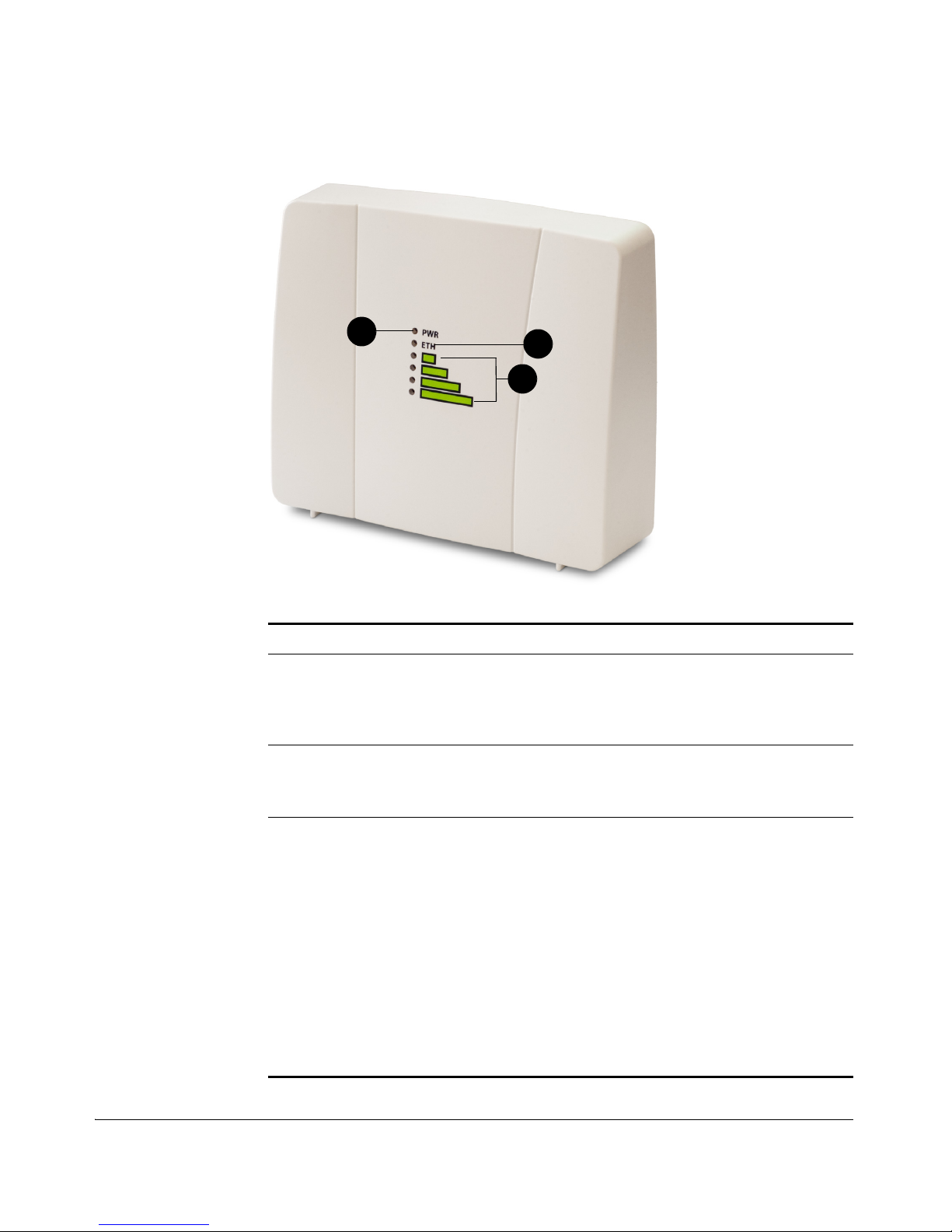
The front panel of MF7211 and MF7211-EXT, shown in Figure 1, features six LED
indicators that can be used to assess the power, Ethernet, and wireless statuses. Refer
to Tab le 3
for more information.
4
Introducing the 7211 Smart Wi-Fi Gateway
Getting to Know the Smart Wi-Fi Gateway Features
Figure 1. MF7211 and MF7211-EXT front panel
Table 3. MF7211 and MF7211-EX LED behavior
Number Name Description
1 PWR (Power) • Off: No power is available, or the Smart Wi-Fi
Gateway is not connected to a power source.
• Green: The Smart Wi-Fi Gateway has completed
booting up and is now operational.
2 ETH (Ethernet) • Off: The Ethernet port is not connected to any
device.
• Green: Traffic is passing through the Ethernet port.
3 Air Quality LEDs The Air Quality LEDs indicate the wireless signal
quality between the Smart Wi-Fi Gateway and your
service provider’s Wireless Broadband Network. The
number of LEDs that are on indicate the wireless
signal quality.
• All LEDs are off: The Smart Wi-Fi Gateway is not
associated with your service provider’s Wireless
Broadband Network.
• One LED is on: Poor signal quality
• Two LEDs are on: Fair signal quality
• Three LEDs are on: Good signal quality
• Four LEDs are on: Excellent signal quality
1
2
3
5
Introducing the 7211 Smart Wi-Fi Gateway
Getting to Know the Smart Wi-Fi Gateway Features
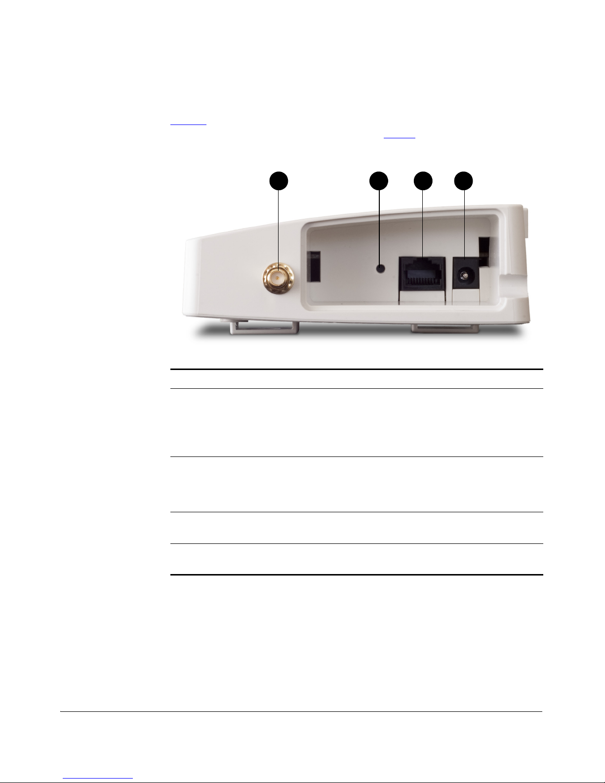
Side Panel Features
Figure 2 shows the side panel of the MF7211 and MF7211-EXT models. For a
description of each side panel element, refer to Ta bl e 4
.
Figure 2. MF7211 and MF7211-EXT side panel
Table 4. MF7211 and MF7211-EXT side panel features
Number Name Description
1 External antenna
connector (MF7211EXT model only)
If you want to extend the range of your wireless
network, you can connect an external antenna to this
connector. For more information on the antenna
types that MF7211-EXT supports, refer to the
Regulatory Flyer that ships with the device.
2 Reset button Pressing and quickly releasing this button reboots the
Smart Wi-Fi Gateway. Pressing and holding it for five
seconds resets the Smart Wi-Fi Gateway to factory
defaults.
3 Ethernet port An RJ-45 port that supports 10/100Mbps
connections.
4 Power adapter
socket
Connect the supplied power adapter to this socket
to supply power to the Smart Wi-Fi Gateway.
1 2 3 4
6
Introducing the 7211 Smart Wi-Fi Gateway
Getting to Know the Smart Wi-Fi Gateway Features
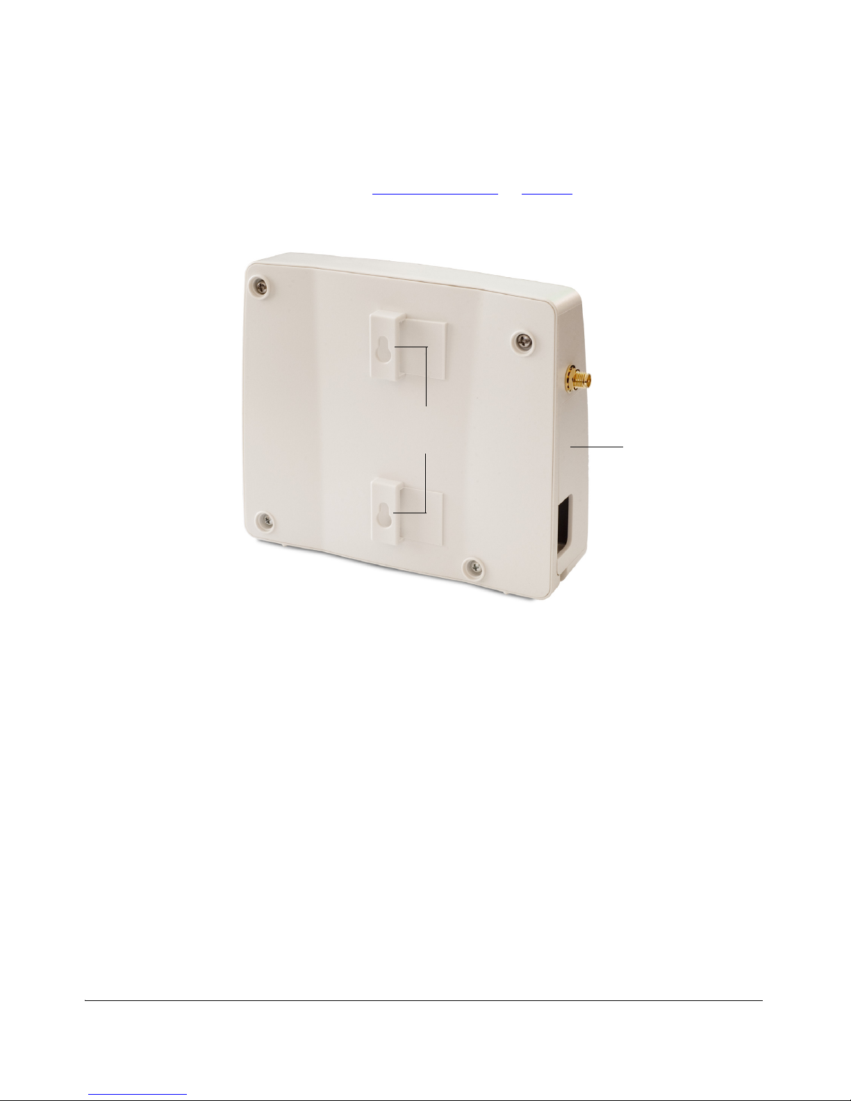
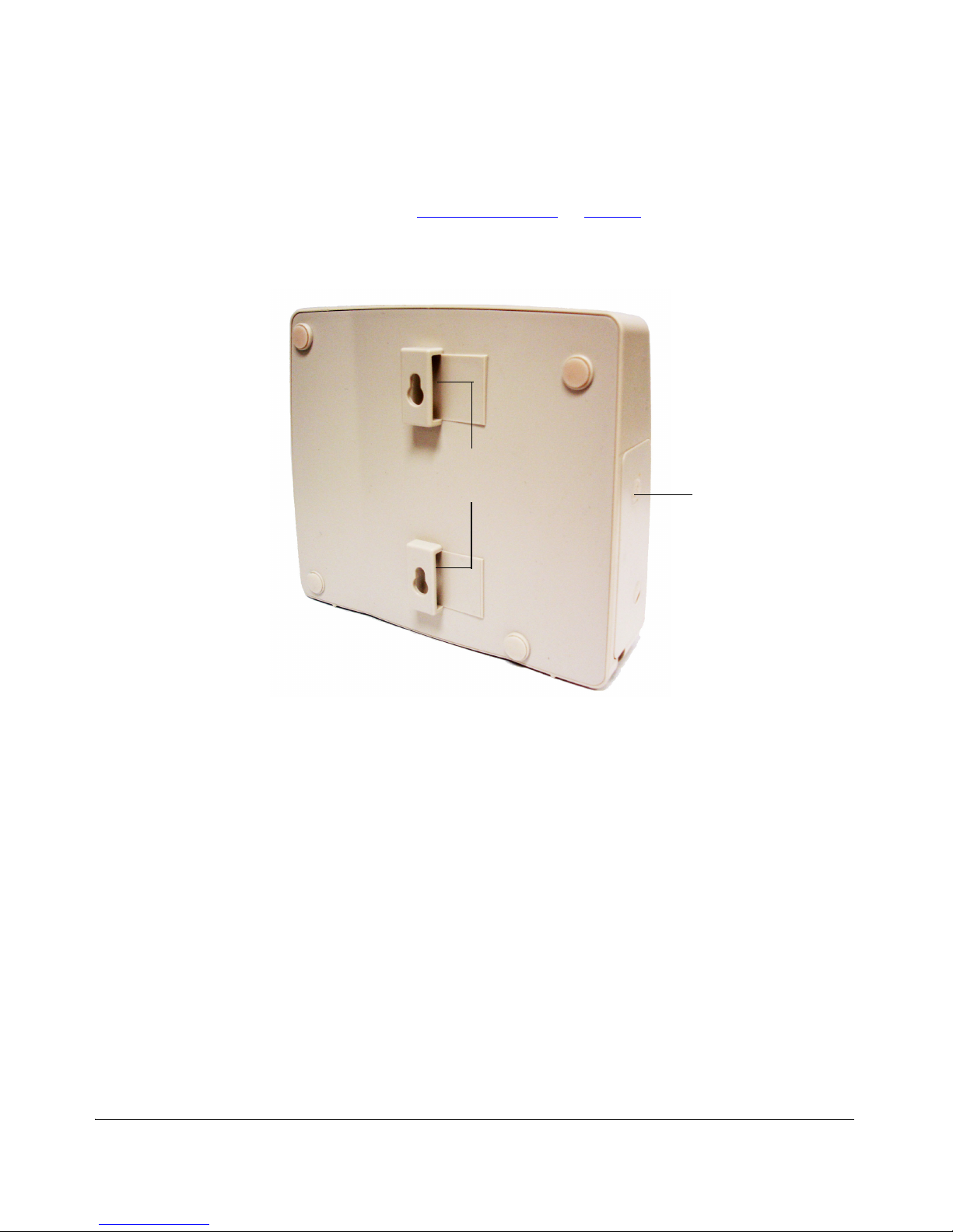
Rear Panel Features
The rear panel has two mounting slots that you can use to mount the device on a wall
or to a pole. Refer to “
Mount the Device” on page 23 to learn how to use these two
mounting slots.
Figure 3. MF7211 and MF7211-EXT rear panel
Mounting slots
Side panel cover

7
Introducing the 7211 Smart Wi-Fi Gateway
Getting to Know the Smart Wi-Fi Gateway Features
MF7211-Outdoor Model
This section describes the physical features of the MF7211-Outdoor model.
Side Panel Features
Figure 4 shows the side panel of the MF7211-Outdoor model. For a description of
each side panel element, refer to Tab l e 5
.
Figure 4. MF7211-Outdoor side panel
Table 5. MF7211-Outdoor side panel features
Number Name Description
1 Power LED • Off: No power is available, or the Smart Wi-Fi
Gateway is not connected to a power source.
• Green: The Smart Wi-Fi Gateway has completed
booting up and is now operational.
2 Ethernet LED • Off: The Ethernet port is not connected to any
device.
• Green: Traffic is passing through the Ethernet port.
1 2
4
5
3

8
Introducing the 7211 Smart Wi-Fi Gateway
Getting to Know the Smart Wi-Fi Gateway Features
3 Air Quality LEDs The Air Quality LEDs indicate the wireless signal
quality between the Smart Wi-Fi Gateway and your
service provider’s Wireless Broadband Network. The
number of LEDs that are on indicate the wireless
signal quality.
• All LEDs are off: The Smart Wi-Fi Gateway is not
associated with your service provider’s Wireless
Broadband Network.
• One LED is on: Poor signal quality
• Two LEDs are on: Fair signal quality
• Three LEDs are on: Good signal quality
• Four LEDs are on: Excellent signal quality
4 Reset button Pushing and quickly releasing this button reboots the
Smart Wi-Fi Gateway. Pushing and holding it for five
seconds resets the Smart Wi-Fi Gateway to factory
defaults.
5 Ethernet port An RJ-45 port that supplies Power over Ethernet (PoE)
and supports 10/100Mbps connections.
Table 5. MF7211-Outdoor side panel features
Number Name Description
9
Introducing the 7211 Smart Wi-Fi Gateway
Getting to Know the Smart Wi-Fi Gateway Features
Rear Panel Features
The rear panel has two mounting slots that you can use to mount the device on a wall
or to a pole. Refer to “
Mount the Device” on page 23 to learn how to use these two
mounting slots.
Figure 5. MF7211-Outdoor rear panel
Mounting slots
Side panel cover

10
Introducing the 7211 Smart Wi-Fi Gateway
Getting to Know the Smart Wi-Fi Gateway Features

11
2
Installing the Smart Wi-Fi Gateway
In This Chapter
Installing the MF7211/MF7211-EXT Model
. . . . . . . . . . . . . . . . . . . . . . . . . . . . . .12
Installing the MF7211-Outdoor Model . . . . . . . . . . . . . . . . . . . . . . . . . . . . . . . . . 18

12
Installing the Smart Wi-Fi Gateway
Installing the MF7211/MF7211-EXT Model
The installation procedures for the MF7211/MF7211-EXT and MF7211-Outdoor
models are slightly different. Refer to the installation procedure for the Smart Wi-Fi
Gateway model that you have.
■ Installing the MF7211/MF7211-EXT Model
■ Installing the MF7211-Outdoor Model
Installing the MF7211/MF7211-EXT Model
Before starting with the installation, make sure that you have the following items that
are required for the installation ready:
■ A computer with a Web browser
■ One CAT5 Ethernet cable (supplied with the device)
■ Your service provider’s Wireless Broadband Network SSID and security settings.
You will need to enter these settings on the device’s Web interface to enable it to
connect to the Wireless Broadband Network service.
Step 1: Prepare the Administrative Computer
The administrative computer is the computer that you will be using to access the
device’s Web interface. To access the Web interface, the administrative computer
must be configured to obtain an IP address automatically.
1. Power on your computer.
2. Go to the network connection settings.
• On Windows 2000, click Start > Settings > Network, and then click Dialup
Connections.
• On Windows XP, click Start > Settings > Control Panel > Network
Connections.
3. Double-click the icon for Local Area Connection.
4. In the Local Area Connection Properties window, select Internet Protocol (TCP/
IP), and then click Properties.
5. Select Obtain an IP address automatically, and then click OK to exit the TCP/IP
Properties window.
6. Click OK to exit the Local Area Connection Properties window.
Step 2: Connect the Device to a Power Source and
the Admin Computer
1. Take out the power adapter that was shipped with the device.
2. Connect the power jack to the DC IN port on the side panel, and then connect
the power adapter to a power source or to a surge protector that is plugged into
a power source.
13
Installing the Smart Wi-Fi Gateway
Installing the MF7211/MF7211-EXT Model
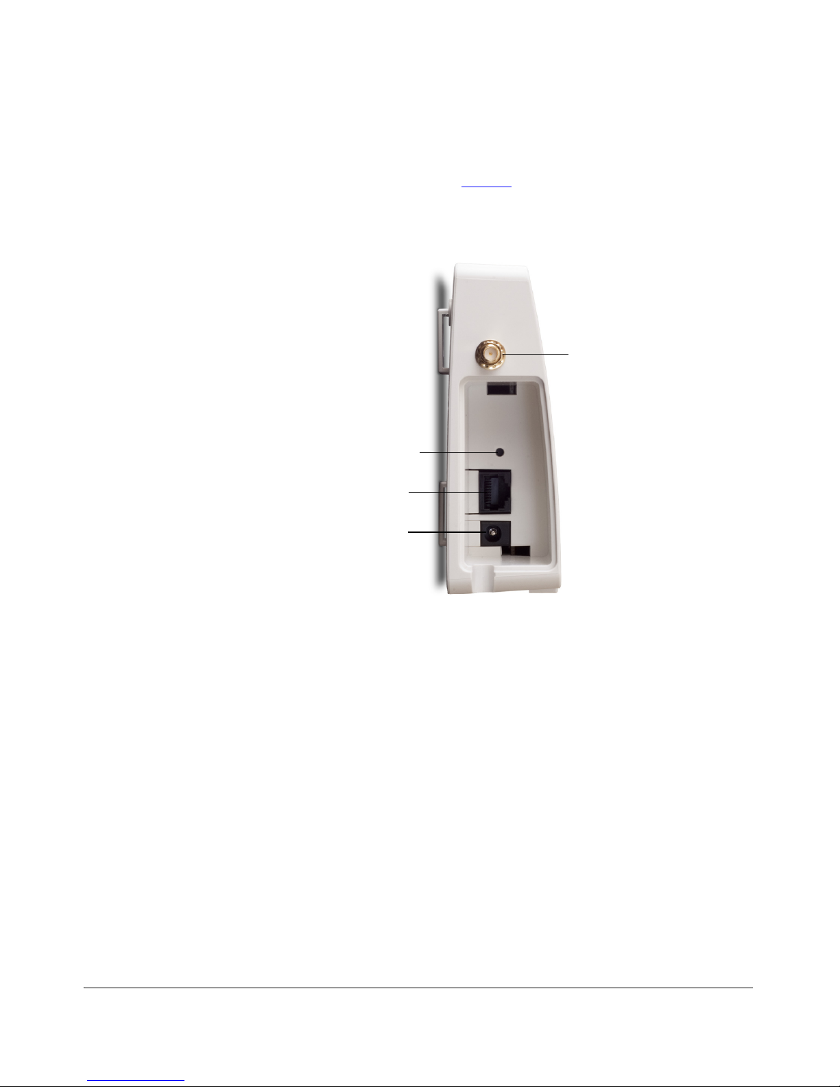
3. Take out the CAT5 Ethernet cable. Connect one end of the CAT5 Ethernet cable
to the Ethernet port on your computer, and then connect the other end to the
Ethernet port on the device (see Figure 6
).
Figure 6. Side panel of Indoor/EXT Smart Wi-Fi Gateway
Step 3: Configure the Device Using the Quick Start
Wizard
Before you start this step, make sure you have already obtained the Wireless Broadband Network SSID and security settings from your service provider.
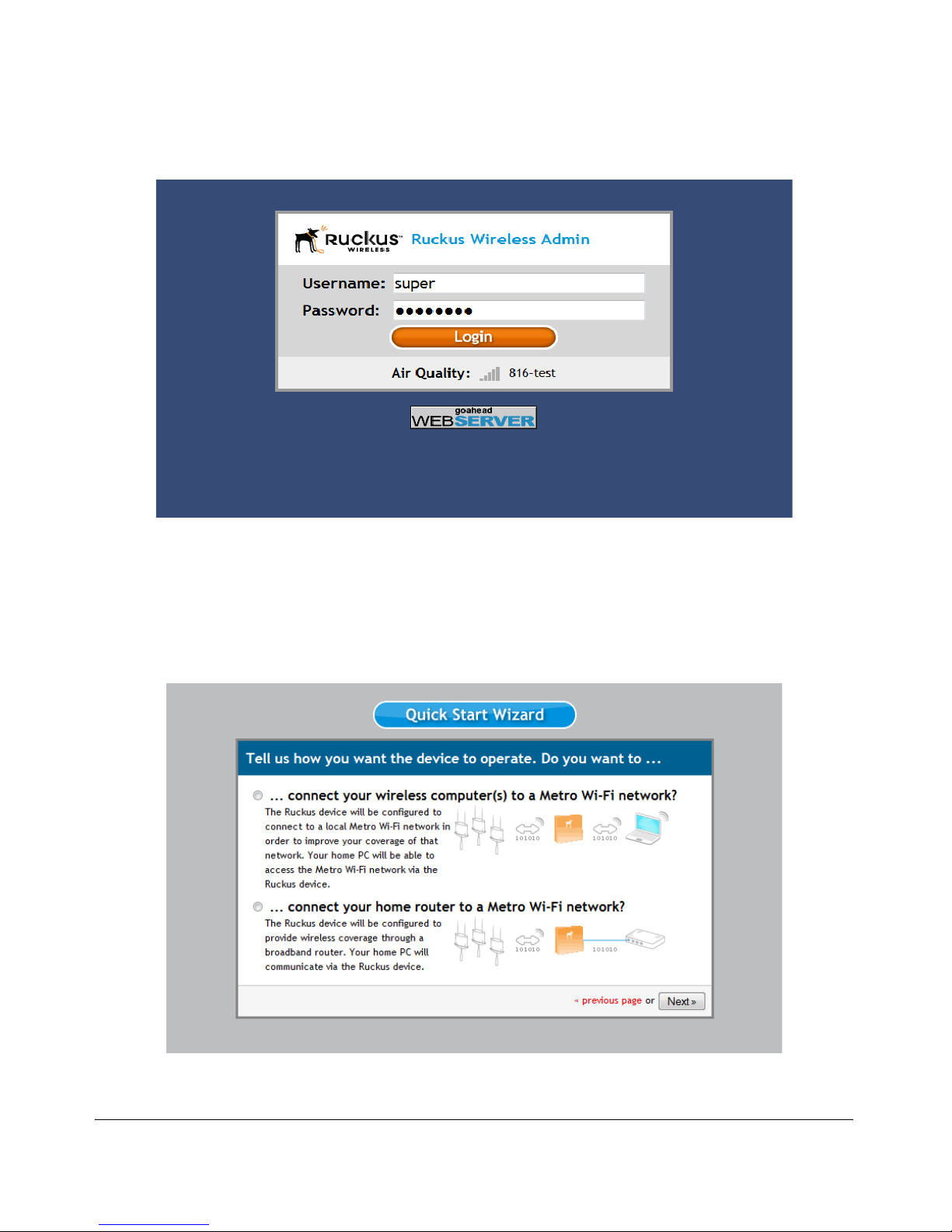
1. On your computer, open a Web browser window.
2. In the address or location bar, enter 192.168.30.1.
3. When the login screen appears, type super as the user name and sp-admin as
the password.
Ethernet port
Reset button
External antenna
connector (EXT
model only)
DC IN port
14
Installing the Smart Wi-Fi Gateway
Installing the MF7211/MF7211-EXT Model
Figure 7. Web interface login page
4. Click the Login button. The Web interface welcome page appears and asks you
if you want to use the quick start wizard to set up the device.
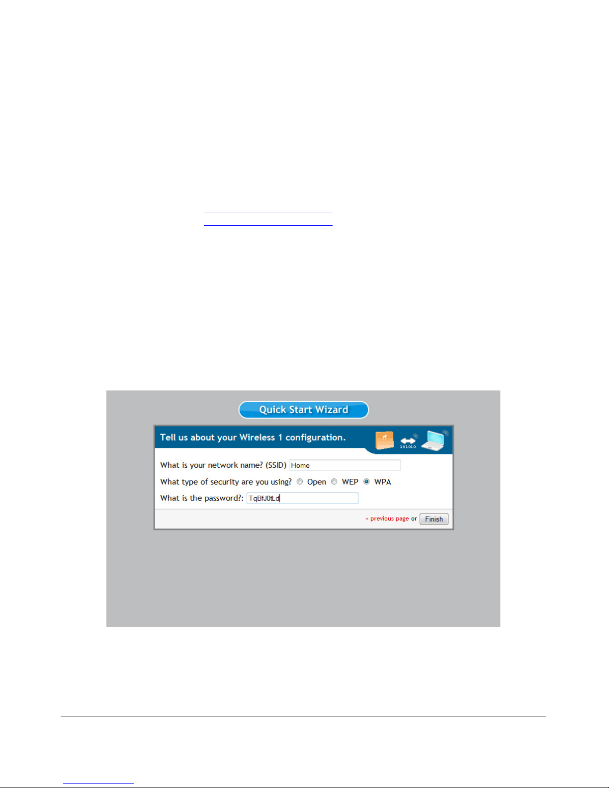
5. Click YES I want to use the wizard. The first page of the Quick Start Wizard
appears.
Figure 8. First page of the Quick Start Wizard
15
Installing the Smart Wi-Fi Gateway
Installing the MF7211/MF7211-EXT Model
6. Select the topology that best describes your network setup, and then click Next.
The two topology options include:
• connect your wireless computer(s) to a Metro Wi-Fi network (Router mode)
• connect your home router to a Metro Wi-Fi network (Bridge mode)
The device checks for available wireless networks with which it can associate and
displays these networks on the next page.
7. Complete the remaining steps for the topology option that you selected:
• If You Selected Router Mode
• If You Selected Bridge Mode
If You Selected Router Mode
1. Click the option button for the wireless network with which you want the device
to associate. If that wireless network is using encryption or authentication, type
the security settings in the boxes that appear.
2. Click Next. The Wireless 1 configuration page appears. Wireless 1 is one of your
two home WLANs. Wireless clients on your home network will need to associate
with this WLAN to gain access to the Internet (via your service provider’s Wireless
Broadband Network).
Figure 9. Wireless 1 configuration page
3. Configure your home WLAN settings by answering the following questions:
• What is your network name? (SSID): Type a name that you want to assign to
this WLAN. This is the WLAN name that wireless clients will connect to.

16
Installing the Smart Wi-Fi Gateway
Installing the MF7211/MF7211-EXT Model
• What type of security are you using?: Select the type of wireless security that
you want to use. Options include Open (no security), WEP, and WPA. If you
select WEP or WPA, you must type a password in the box provided.
WEP passwords must consist of either 5 or 13 characters. WPA passwords must
be between 8 and 63 characters.
When users connect to this WLAN, they will be prompted for this password
before they are allowed access to the wireless network.
4. Click Finish. A summary of the settings that you have configured appears.
5. Click Reboot to apply your changes. A popup message appears, informing you
that the reboot process may take a few minutes.
6. Click OK. When the reboot process is complete, a popup message appears and
prompts you to click the OK button to reconnect to the Web interface.
7. Click the OK button.
You have completed configuring the device using the Quick Start Wizard.
If You Selected Bridge Mode
1. Click the option button for the wireless network with which you want the device
to associate. If that wireless network is using encryption or authentication, type
the security settings in the boxes that appear.
2. Click Next. A summary of the settings that you have configured appears.
3. Click Reboot to apply your changes. A popup message appears, informing you
that the reboot process may take a few minutes.
4. Click OK. When the reboot process is complete, a popup message appears and
prompt you to click the OK button to reconnect to the Web interface.
5. Click the OK button.
You have completed configuring the device using the Quick Start Wizard.
Step 4: Verify That Your Computer Can Connect to
the Internet
After you complete the Quick Start Wizard, your computer should now be able to
connect to your service provider’s Wireless Broadband Network and the Internet via
the device. Perform these steps to check.
1. On your computer, open a browser window.
2. In the address or location bar, type
www.ruckuswireless.com.
If the Ruckus Wireless Web site loads in your browser, you are able to connect to the
Internet.
Congratulations! Your wireless network is now active and ready for use.

17
Installing the Smart Wi-Fi Gateway
Installing the MF7211/MF7211-EXT Model
What to Do Next
■ If you want to become familiar with the Smart Wi-Fi Gateway Web interface, refer
to “
Navigating the Web Interface” on page 25.
■ If you want to perform additional configuration tasks (such as configuring the
system and wireless settings and controlling access to the wireless network), refer
to “
Configuring the Smart Wi-Fi Gateway” on page 31.
■ If you want to perform management tasks (such as changing the administrative
password, upgrading the firmware, or running diagnostics), refer to “
Managing
the Smart Wi-Fi Gateway” on page 63.
18
Installing the Smart Wi-Fi Gateway
Installing the MF7211-Outdoor Model
Installing the MF7211-Outdoor Model
Before starting with the installation, make sure that you have the following items that
are required for the installation ready:
■ A computer with a Web browser
■ Two CAT5 Ethernet cables
■ The PoE injector and power adapter that are supplied with the device.
CAUTION: The Outdoor Smart Wi-Fi Gateway is not 802.3af compliant. You must use
only the PoE injector and power adapter that are supplied with the device.
■ Your service provider’s Wireless Broadband Network SSID and security settings.
You will need to enter these settings on the device’s Web interface to enable it to
connect to the Wireless Broadband Network service.
Step 1: Prepare the Administrative Computer
The administrative computer is the computer that you will be using to access the
device’s Web interface. To access the Web interface, the administrative computer
must be configured to obtain an IP address automatically.
1. Power on your computer.
2. Go to the network connection settings.
• On Windows 2000, click Start > Settings > Network, and then click Dialup
Connections.
• On Windows XP, click Start > Settings > Control Panel > Network
Connections.
3. Double-click the icon for Local Area Connection.
4. In the Local Area Connection Properties window, select Internet Protocol (TCP/
IP), and then click Properties.
5. Select Obtain an IP address automatically, and then click OK to exit the TCP/IP
Properties window.
6. Click OK to exit the Local Area Connection Properties window.
19
Installing the Smart Wi-Fi Gateway
Installing the MF7211-Outdoor Model
Step 2: Connect the Device to a Power Source and
the Admin Computer
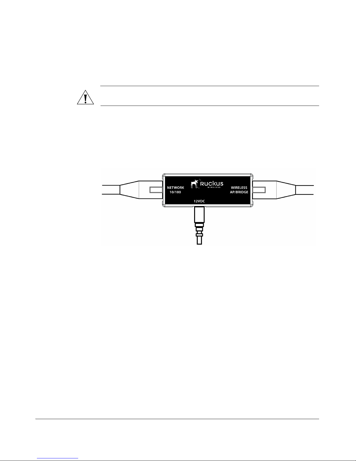
CAUTION: Use only the PoE injector and power adapter that are supplied with this
device.
1. Take out the PoE injector and power adapter that were shipped with the device.
2. Connect the power jack to the 12VDC port on the PoE injector, and then connect
the power adapter to a power source or to a surge protector that is plugged into
a power source.
Figure 10.Connect the Ethernet cables and power adapter to the PoE injector
3. Take one of the CAT5 Ethernet cables. Connect one end of the CAT5 Ethernet
cable to the Ethernet port on your computer, and then connect the other end to
the NETWORK 10/100 port on the PoE injector.
4. Take the other Ethernet cable. Connect one end to the WIRELESS AP/BRIDGE
port on the PoE injector, and then connect the other end to the Ethernet port on
the device (see figure).
 Loading...