

Page 1

DEPLOYMENT GUIDE
Ruckus ICX Switch Port Extender
Deployment Guide
Supporting FastIron Software Release 08.0.70
Part Number: 53-1004186-03
Publication Date: 19 July 2018
Page 2

Copyright, Trademark and Proprietary Rights
Information
©
2018 ARRIS Enterprises LLC. All rights reserved.
No part of this content may be reproduced in any form or by any means or used to make any derivative work (such as
translation, transformation, or adaptation) without written permission from ARRIS International plc and/or its aliates ("ARRIS").
ARRIS reserves the right to revise or change this content from time to time without obligation on the part of ARRIS to provide
notication of such revision or change.
Export Restrictions
These products and associated technical data (in print or electronic form) may be subject to export control laws of the United
States of America. It is your responsibility to determine the applicable regulations and to comply with them. The following notice
is applicable for all products or technology subject to export control:
These items are controlled by the U.S. Government and authorized for export only to the country of ultimate destination for use by the
ultimate consignee or end-user(s) herein identied. They may not be resold, transferred, or otherwise disposed of, to any other country
or to any person other than the authorized ultimate consignee or end-user(s), either in their original form or after being incorporated
into other items, without rst obtaining approval from the U.S. government or as otherwise authorized by U.S. law and regulations.
Disclaimer
THIS CONTENT AND ASSOCIATED PRODUCTS OR SERVICES ("MATERIALS"), ARE PROVIDED "AS IS" AND WITHOUT WARRANTIES OF
ANY KIND, WHETHER EXPRESS OR IMPLIED. TO THE FULLEST EXTENT PERMISSIBLE PURSUANT TO APPLICABLE LAW, ARRIS
DISCLAIMS ALL WARRANTIES, EXPRESS OR IMPLIED, INCLUDING, BUT NOT LIMITED TO, IMPLIED WARRANTIES OF
MERCHANTABILITY AND FITNESS FOR A PARTICULAR PURPOSE, TITLE, NON-INFRINGEMENT, FREEDOM FROM COMPUTER VIRUS,
AND WARRANTIES ARISING FROM COURSE OF DEALING OR COURSE OF PERFORMANCE. ARRIS does not represent or warrant
that the functions described or contained in the Materials will be uninterrupted or error-free, that defects will be corrected, or
are free of viruses or other harmful components. ARRIS does not make any warranties or representations regarding the use of
the Materials in terms of their completeness, correctness, accuracy, adequacy, usefulness, timeliness, reliability or otherwise. As
a condition of your use of the Materials, you warrant to ARRIS that you will not make use thereof for any purpose that is unlawful
or prohibited by their associated terms of use.
Limitation of Liability
IN NO EVENT SHALL ARRIS, ARRIS AFFILIATES, OR THEIR OFFICERS, DIRECTORS, EMPLOYEES, AGENTS, SUPPLIERS, LICENSORS
AND THIRD PARTY PARTNERS, BE LIABLE FOR ANY DIRECT, INDIRECT, SPECIAL, PUNITIVE, INCIDENTAL, EXEMPLARY OR
CONSEQUENTIAL DAMAGES, OR ANY DAMAGES WHATSOEVER, EVEN IF ARRIS HAS BEEN PREVIOUSLY ADVISED OF THE
POSSIBILITY OF SUCH DAMAGES, WHETHER IN AN ACTION UNDER CONTRACT, TORT, OR ANY OTHER THEORY ARISING FROM
YOUR ACCESS TO, OR USE OF, THE MATERIALS. Because some jurisdictions do not allow limitations on how long an implied
warranty lasts, or the exclusion or limitation of liability for consequential or incidental damages, some of the above limitations
may not apply to you.
Trademarks
ARRIS, the ARRIS logo, Ruckus, Ruckus Wireless, Ruckus Networks, Ruckus logo, the Big Dog design, BeamFlex, ChannelFly,
EdgeIron, FastIron, HyperEdge, ICX, IronPoint, OPENG, SmartCell, Unleashed, Xclaim, ZoneFlex are trademarks of ARRIS
International plc and/or its aliates. Wi-Fi Alliance, Wi-Fi, the Wi-Fi logo, the Wi-Fi CERTIFIED logo, Wi-Fi Protected Access (WPA),
the Wi-Fi Protected Setup logo, and WMM are registered trademarks of Wi-Fi Alliance. Wi-Fi Protected Setup™, Wi-Fi Multimedia™,
and WPA2™ are trademarks of Wi-Fi Alliance. All other trademarks are the property of their respective owners.
2 Part Number: 53-1004186-03
Ruckus ICX Switch Port Extender Deployment Guide
Page 3

Contents
Preface...................................................................................................................................................................................................5
Overview....................................................................................................................................................................................................... 5
Purpose of This Document.........................................................................................................................................................................6
Audience....................................................................................................................................................................................................... 6
Objectives..................................................................................................................................................................................................... 7
Document History....................................................................................................................................................................................... 7
SPX Technical Architecture................................................................................................................................................................. 9
Control Bridge.............................................................................................................................................................................................. 9
Port Extenders............................................................................................................................................................................................. 9
Supported SPX Topologies................................................................................................................................................................. 11
Unsupported SPX Topologies............................................................................................................................................................ 15
Scaling (Supported Topologies).........................................................................................................................................................19
SPX Construction Methods................................................................................................................................................................21
Prerequisites.............................................................................................................................................................................................. 21
Valid Port Combinations...........................................................................................................................................................................21
Bill of Materials.................................................................................................................................................................................. 23
Deployment Considerations............................................................................................................................................................. 27
Bringing Up SPX.................................................................................................................................................................................. 29
Conguration Notes..................................................................................................................................................................................29
Reference Topology...................................................................................................................................................................................30
Conguring the CB.................................................................................................................................................................................... 30
Conguring the PE.....................................................................................................................................................................................32
SPX PE Ring..........................................................................................................................................................................................37
Overview.....................................................................................................................................................................................................37
How a PE Ring Works with Dierent Types of Trac............................................................................................................................38
Unicast Trac.....................................................................................................................................................................................38
Multicast/Broadcast and Unknown Unicast Trac........................................................................................................................39
Deployment Scenarios.......................................................................................................................................................................41
Reference Topology...................................................................................................................................................................................41
Deployment Scenario 1: Deploying a PE Ring in an Existing Campus Fabric Domain...................................................................... 42
Deployment Scenario 2: Deploying a PE Ring Using ZTP......................................................................................................................43
Deployment Scenario 3: Adding a New PE Unit to an Existing PE Ring.............................................................................................. 44
Deployment Scenario 4: Replacing a PE in an Existing PE Ring........................................................................................................... 48
Deployment Scenario 5: Moving SPX Links Between Modules in a PE Ring.......................................................................................51
Deployment Scenario 6: Adding More Links to a Live SPX Link Using the multi-spx-lag Command...............................................54
Deployment Scenario 7: Removing Links from a Live SPX LAG and Converting the LAG to an SPX Port....................................... 56
Deployment Scenario 8: Changing a PE Ring to a Linear PE Chain..................................................................................................... 59
Image Upgrade................................................................................................................................................................................... 63
Debugging and Verication Commands.......................................................................................................................................... 67
Verication Commands: SPX PE Ring......................................................................................................................................................72
Debugging PE Ring Failures......................................................................................................................................................................74
Ruckus ICX Switch Port Extender Deployment Guide
Part Number: 53-1004186-03 3
Page 4

PE Ring FSM States............................................................................................................................................................................. 77
Running Conguration...................................................................................................................................................................... 79
Best Practices..................................................................................................................................................................................... 81
Zero-Touch Provisioning.................................................................................................................................................................... 85
ZTP Overview............................................................................................................................................................................................. 85
Zero-Touch Deployment Requirements..................................................................................................................................................85
PE Candidate Requirements.................................................................................................................................................................... 86
Topology Requirements............................................................................................................................................................................87
Supported Topologies for Zero-Touch.................................................................................................................................................... 88
Unsupported Topologies for Zero-Touch................................................................................................................................................89
Zero-Touch Features..................................................................................................................................................................................90
SPX Interactive-Setup................................................................................................................................................................................93
Managing PEs.............................................................................................................................................................................................94
SPX Interactive-Setup Enhancement............................................................................................................................................... 95
Zero-Touch Deployment Considerations................................................................................................................................................ 95
Deployment Scenarios..............................................................................................................................................................................96
Deployment Scenario 1: Bringing Up a Complete Campus Fabric Domain with Zero-Touch...................................................96
Deployment Scenario 2: Adding Units to a Ring or Linear Topology Using the SPX Interactive-Setup Utility......................103
Deployment Scenario 3: Migrating an Existing Stack to Campus Fabric...................................................................................108
Deployment Scenario 4: Replacing a PE........................................................................................................................................116
Deployment Scenario 5: Preventing an ICX 7250 or ICX 7450 from Being Discovered by Zero-Touch..................................121
Deployment Scenario 6: Changing PE IDs Using SPX Interactive-Setup....................................................................................122
Deployment Scenario 7: SPX PE Movement: Moving PEs Without Changing IDs.....................................................................126
Deployment Scenario 8: Adding a New Link Between CB-PE or PE-PE to Change Existing Linear Toplogy to Ring Topology
............................................................................................................................................................................................ 128
Deployment Recommendations for ZTP ............................................................................................................................................. 130
Best Practices...........................................................................................................................................................................................131
Debugging Notes.....................................................................................................................................................................................132
4 Part Number: 53-1004186-03
Ruckus ICX Switch Port Extender Deployment Guide
Page 5

Preface
• Overview......................................................................................................................................................................... 5
• Purpose of This Document...........................................................................................................................................6
• Audience......................................................................................................................................................................... 6
• Objectives....................................................................................................................................................................... 7
• Document History......................................................................................................................................................... 7
Overview
Ruckus Campus Fabric technology integrates high-performance, xed-form-factor switches to create a single distributed logical
switch that is independent of physical location and that allows organizations to add ports across the campus whenever and
wherever needed without adding complexity. Traditional three-tier network designs with a "big-box" chassis at the aggregation
and core layers require a signicant up-front investment, but with Ruckus Campus Fabric, switches can be added when needed
and they still perform like one big switch. Switch Port Extender, abbreviated as SPX, is the name of this Campus Fabric solution.
ATTENTION
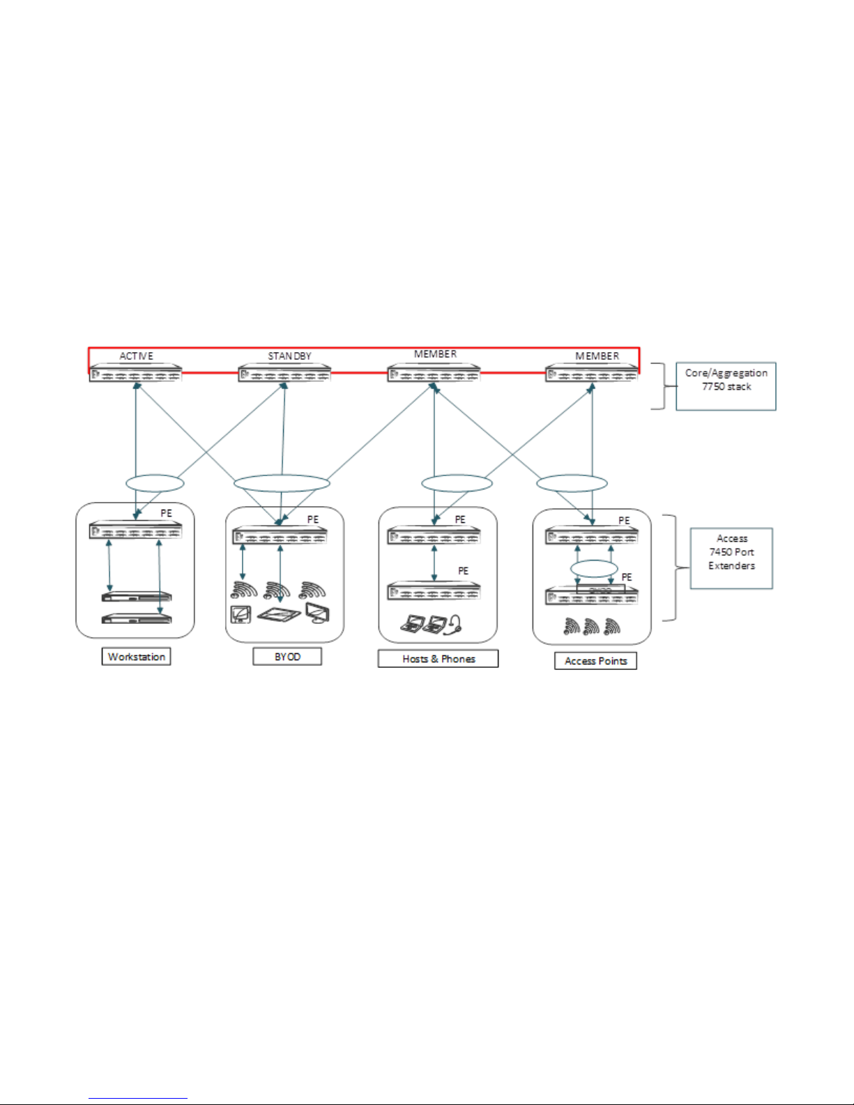
The SPX architecture simplies network management by unifying core, aggregation, and access functions. A core stack
(distributed chassis) serving as the control bridge connects to downstream Switch Port Extender (PE/SPX) units that
aggregate large numbers of access devices. Switch Port Extender creates a more scalable architecture based on IEEE
802.1BR standards.
Advantages of the SPX architecture:
• A centralized point of control and management
• IEEE 802.1BR open-standard-based solution
• STP-free Layer 2 design
• Policy and feature inheritance
• Scale-out using xed switches
The following devices from the Ruckus ICX product family support SPX congurations in FastIron 08.0.50 and later releases:
• Ruckus ICX 7250 Switches (ICX 7250): port extenders
• Ruckus ICX 7450 Switches (ICX 7450): port extenders
• Ruckus ICX 7750 Switches (ICX 7750): control bridge
NOTE
The Ruckus ICX 7250 and ICX 7450-ZP switches are not supported as port extenders in FastIron 08.0.40.
NOTE
The Ruckus ICX 7250-24G switch cannot be used as a PE unit in FastIron 08.0.50.
NOTE
The Ruckus ICX 7150 switch is supported as a port extender in FastIron 08.0.70 and later.
The Ruckus ICX 7750 is a powerful stackable switch that enables simplied distributed chassis deployments for the scale-out
campus aggregation and core networks; helping organizations seamlessly add network capacity in an agile, cost-ecient
manner.
Ruckus ICX Switch Port Extender Deployment Guide
Part Number: 53-1004186-03 5
Page 6
Preface
Purpose of This Document
The Ruckus ICX 7250 and ICX 7450 switches deliver the performance, exibility, and scalability required for enterprise gigabit
Ethernet access deployment. These switches oer market chassis-level performance and reliability with the exibility, cost-
eectiveness, and "pay as you grow" scalability of a stackable solution.
The components of the Ruckus SPX architecture are the Ruckus ICX 7250 and ICX 7450 routers congured as port extenders
(PEs), or PE units, to a set of Ruckus ICX 7750 stack units congured as the 802.1BR control bridge. The ICX 7750 control bridge
(CB) provides a single point of management for the extended network. Active and standby controller functions are retained in the
ICX 7750 (control bridge) stack and continue to provide hitless recovery and extended administrative functions. SPX widely
increases the number of access devices in the network that can be controlled and managed from a single point. The distributed
CB at the center of the SPX architecture manages PE units and hundreds of ports at the network edge.
FIGURE 1 SPX Architecture (Collapsed Access and Core/Aggregation)
Purpose of This Document
This document provides the technical architecture, conguration, deployment scenarios, and use cases for the Ruckus Campus
Fabric Switch Port Extender.
Audience
This document is useful for network designers, system engineers, administrators, and customers.
6 Part Number: 53-1004186-03
Ruckus ICX Switch Port Extender Deployment Guide
Page 7

Preface
Document History
Objectives
The objective of this guide is to assist the administrator in bringing up and conguring the Switch Port Extender. This deployment
guide covers the following topics in depth:
• SPX technical architecture
• SPX topologies
• SPX construction methods
• Adding or replacing a port extender unit
• Migrating from stack to SPX fabric
• Image upgrade
Noteworthy best practices and recommendations are also covered in this guide.
Document History
Date Description
February 2016 Initial version.
January 2017 Support for the ICX 7250 was introduced in FastIron 08.0.50.
July 2018 Support for the ICX 7150 as a port extender was introduced in FastIron 08.0.70; added support for image
upgrade using IPC over Ethernet, and zero-touch enhancements.
Ruckus ICX Switch Port Extender Deployment Guide
Part Number: 53-1004186-03 7
Page 8

8 Part Number: 53-1004186-03
Ruckus ICX Switch Port Extender Deployment Guide
Page 9

SPX Technical Architecture
• Control Bridge................................................................................................................................................................9
• Port Extenders............................................................................................................................................................... 9
Control Bridge
The control bridge (CB) manages port extender (PE) units. It performs switching, routing, and forwarding for PE ports and
provides centralized policy management. The CB uses the Link Layer Discovery Protocol (LLDP) to discover PE units. When the CB
discovers a PE unit, it connects to the PE unit and creates a control plane using Control and Status Protocol (CSP) over the uplink/
cascade port. Each PE port is managed as a virtual port from the CB perspective. The CB sets up each PE unit for trac
forwarding and creates multicast and unicast forwarding tables through CSP.
The Ruckus ICX 7750 acts as control bridge. The control bridge can be a standalone device or a stack. The control bridge stack
can have a maximum of four units with a ring or linear topology. The ICX 7750 supports long-distance stacking spanning up to 10
kilometers between stack units.
Refer to Bill of Materials on page 23 for qualied optics and port combinations supported for long-distance stacking on the ICX
7750.
The models of the ICX 7750 have a similar hardware design. The dierences lie mostly in the external interfaces. All models
support the 802.1BR standard. The ICX 7750 has the following models:
• ICX7750-48F
• ICX7750-48C
• ICX7750-32Q
Port Extenders
The port extenders (PEs) provide a data path between end hosts and the control bridge and use LLDP to advertise 802.1BR
capabilities to the CB over the upstream port or LAG. If capabilities match, the PE uses CSP to attach to the CB. The PE reports the
number of available ports to the CB, and the CB allocates an ECID for each PE port. The PE units perform hardware-based
multicast and broadcast replication.
The Ruckus ICX 7250 and ICX 7450 act as port extender units, which are managed by the control bridge. All ICX 7150 models can
be congured as PE units beginning with FastIron 08.0.70 and later.
PE units rely on the CB for most network functions.
The ICX 7450 has six dierent models based on port density, PoE capability, and port type; in addition, each of the models
supports four dierent ex modules. The ICX 7450 has the following models:
• ICX7450-24
• ICX7450-24P
• ICX7450-48
• ICX7450-48P
• ICX7450-48F
• ICX7450-ZP
Ruckus ICX Switch Port Extender Deployment Guide
Part Number: 53-1004186-03 9
Page 10

SPX Technical Architecture
Port Extenders
NOTE
The Ruckus ICX 7450-ZP does not support 802.1BR in FastIron 08.0.40.
The ICX 7250 has the following models:
• ICX7250-24
• ICX7250-24P
• ICX7250-48
• ICX7250-48P
NOTE
The Ruckus ICX 7250-24G does not support 802.1BR in FastIron 08.0.50.
The ICX 7150 has the following models:
• ICX7150-C12
• ICX7150-24
• ICX7150-24P
• ICX 7150-48F
• ICX7150-48P
• ICX7150-48ZP
NOTE
SPX LAGs on ICX 7150 PEs are limited to eight ports in FastIron 08.0.70.
NOTE
ICX 7150 devices require a PoD license for ports that will be used for 10-Gbps connections. The exception is the ICX
7150-48XP model, which is shipped with two 10-Gbps ports but requires a PoD license for any additional 10-Gbps
connections.
NOTE
The ICX 7150 uses trust-based licenses. Refer to the Ruckus FastIron Software Licensing Guide for information on installing
ICX 7150 licenses.
10 Part Number: 53-1004186-03
Ruckus ICX Switch Port Extender Deployment Guide
Page 11
Supported SPX Topologies
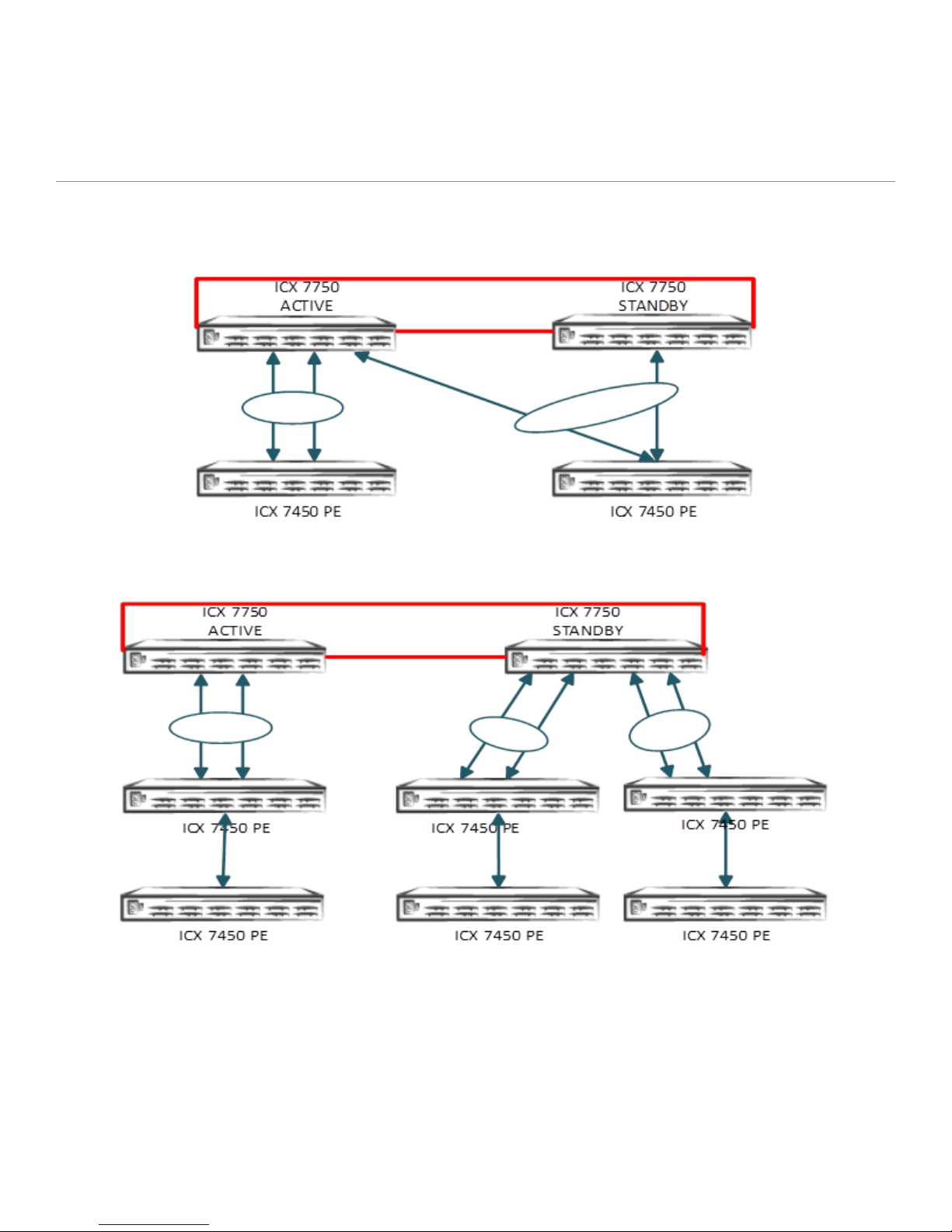
FIGURE 2 Topology 1: SPX-LAG Spanned Across the CB Stack Unit
FIGURE 3 Topology 2: Multiple PE Chains Connected to the Same CB Unit
Ruckus ICX Switch Port Extender Deployment Guide
Part Number: 53-1004186-03 11
Page 12

Supported SPX Topologies
FIGURE 4 Topology 3: SPX-LAG Between PE Units
FIGURE 5 Topology 4: SPX with Standalone CB Unit
12 Part Number: 53-1004186-03
Ruckus ICX Switch Port Extender Deployment Guide
Page 13
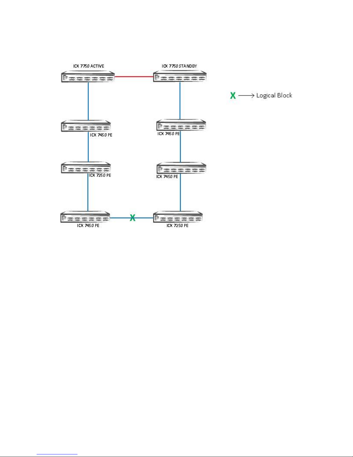
FIGURE 6 Topology 5: SPX PE Ring Topology from PE to CB Units
Supported SPX Topologies
The green X indicates the location of the logical block for data ow through the PE ring. The logical block is placed on the link that
comes up last during the PE ring formation.
Ruckus ICX Switch Port Extender Deployment Guide
Part Number: 53-1004186-03 13
Page 14

14 Part Number: 53-1004186-03
Ruckus ICX Switch Port Extender Deployment Guide
Page 15
Unsupported SPX Topologies
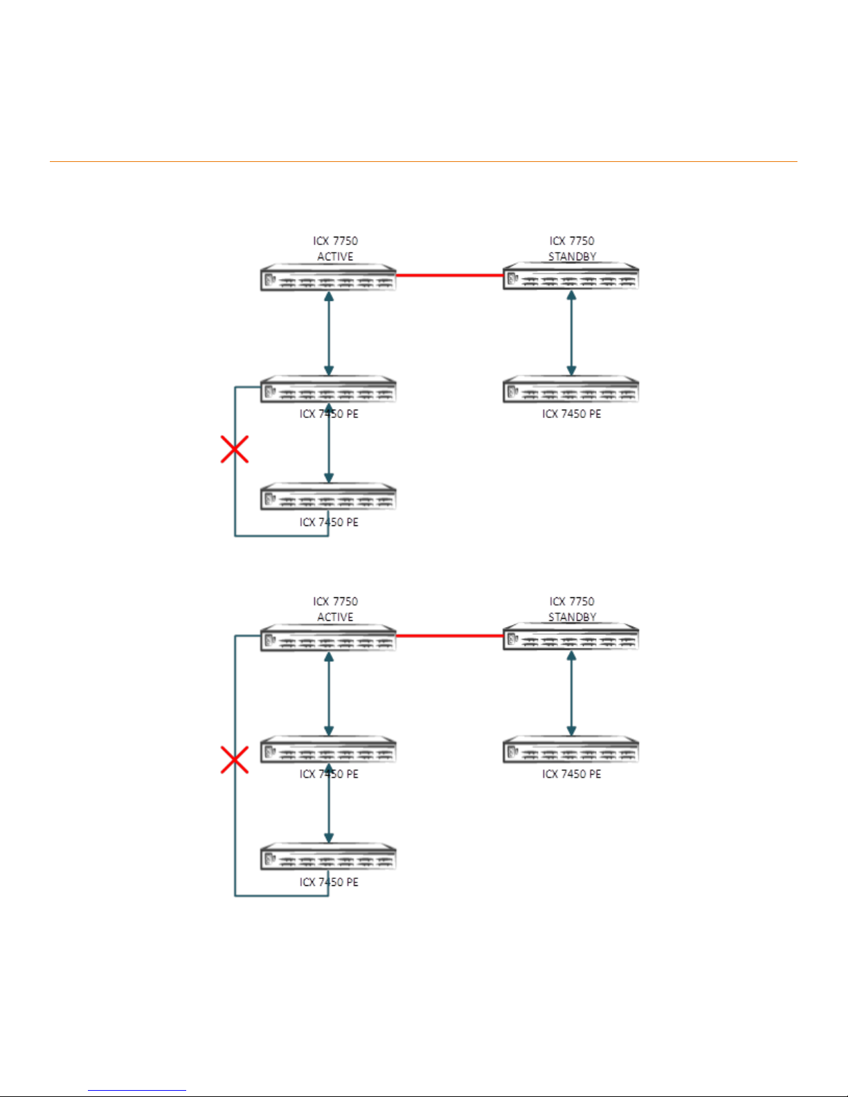
FIGURE 7 Topology 1: Ring Topology Within a PE Chain
FIGURE 8 Topology 2: Ring Topology from PE to CB Units Is Not Supported in 08.0.40
Ruckus ICX Switch Port Extender Deployment Guide
Part Number: 53-1004186-03 15
Page 16

Unsupported SPX Topologies
FIGURE 9 Topology 3: SPX-LAG Spanning Multiple PE Chains
FIGURE 10 Topology 4: More Than One PE Unit Connected to a Transit PE
16 Part Number: 53-1004186-03
Ruckus ICX Switch Port Extender Deployment Guide
Page 17
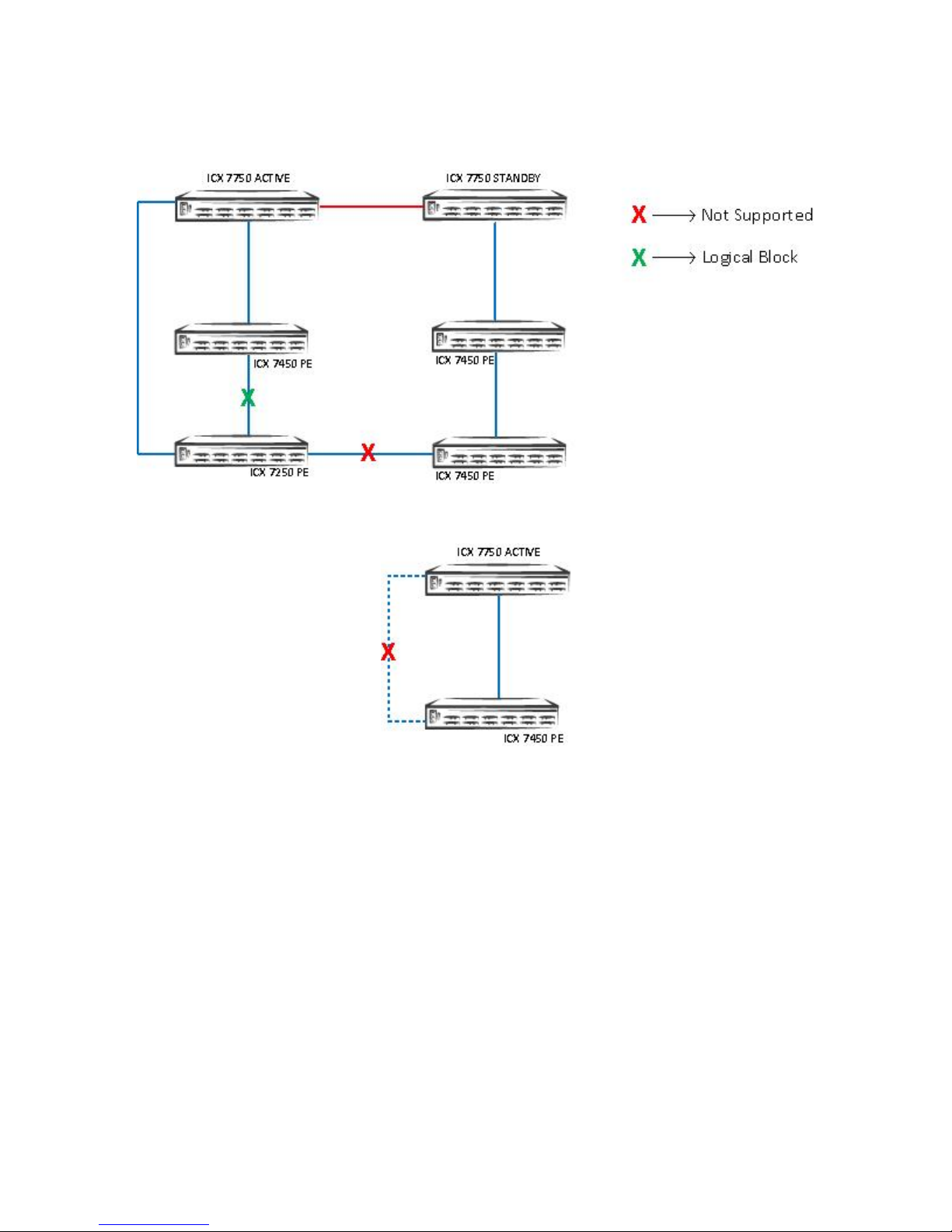
FIGURE 11 Topology 5: Edge PE Connected to an Existing PE Ring
Unsupported SPX Topologies
FIGURE 12 Topology 6: SPX PE Ring with One PE
Ruckus ICX Switch Port Extender Deployment Guide
Part Number: 53-1004186-03 17
Page 18
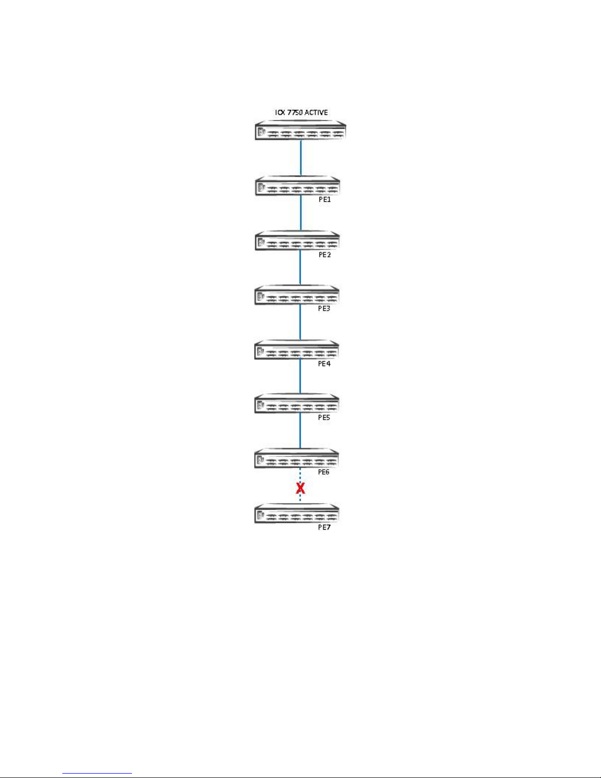
Unsupported SPX Topologies
FIGURE 13 Topology 7: PE Chains of Seven or More PEs
18 Part Number: 53-1004186-03
Ruckus ICX Switch Port Extender Deployment Guide
Page 19
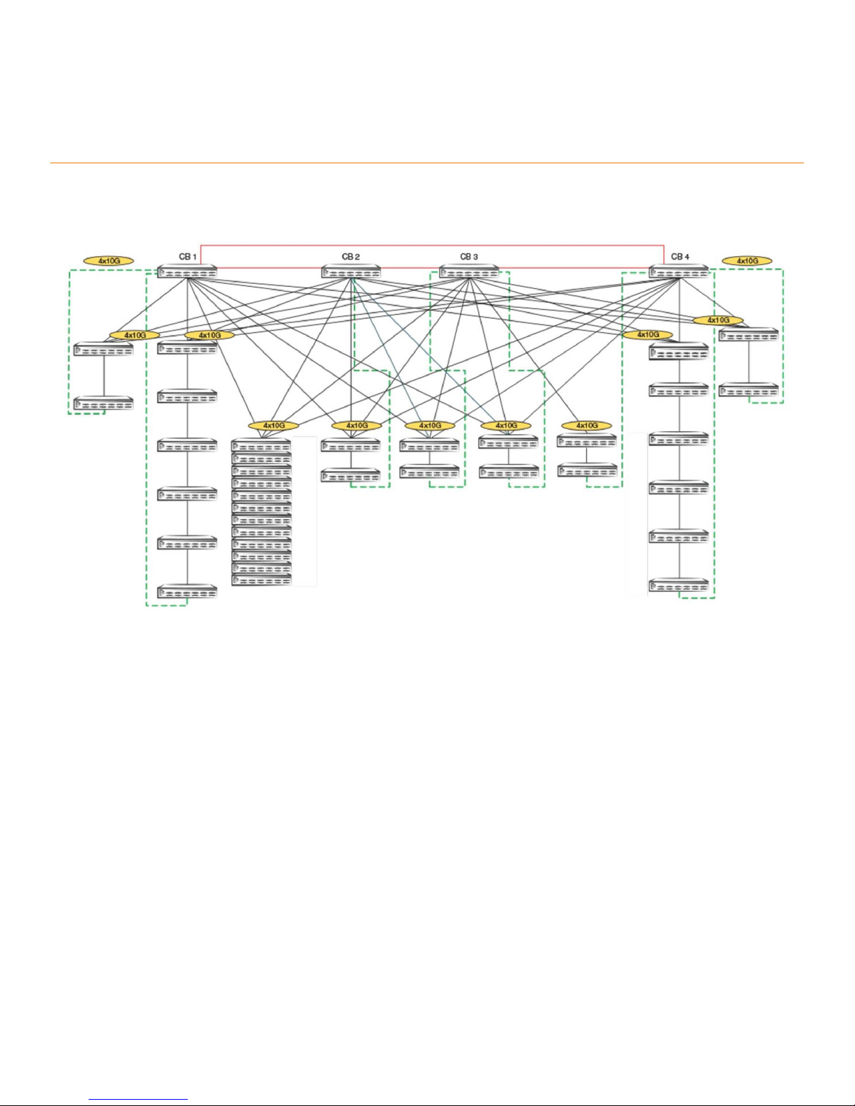
Scaling (Supported Topologies)
FIGURE 14 Scaled Topology Including SPX (PE) Ring and PE Chains
Scalability Limits
• 4 CB stack units (ICX 7750)
• 36 PE units (ICX 7450, ICX 7250, and ICX 7150)
• 6 PE units per chain cascade depth
• 1500 PE ports
• 4 VLANs per PE port (including the default VLAN) , 32 RSTP instances or 8 MSTP instances
• 12 directly connected PEs
• 8 PE rings
• 8 PE rings and 12 directly connected PEs running in parallel
• 32 SPX ports per CB unit (For example, on a 2-unit CB stack, there are 32 SPX ports on the CB active controller and 32
SPX ports on the CB standby controller.)
Ruckus ICX Switch Port Extender Deployment Guide
Part Number: 53-1004186-03 19
Page 20

Scaling (Supported Topologies)
ATTENTION
Use port extender ports to hook to APs, phones, and PoE devices. Use control bridge ports to connect to servers, VMs,
and so on.
Do not hook the PE ports to any other routers and switches. Do not deploy where compact switches are connected to
the PE ports where the compact switches are not part of the Campus Fabric, but standalone units.
Disable LLDP on user ports where it is not required for the FastIron system to scale, and avoid high CPU issues.
Turn o FDP and CDP in scaled environments.
20 Part Number: 53-1004186-03
Ruckus ICX Switch Port Extender Deployment Guide
Page 21

SPX Construction Methods
• Prerequisites................................................................................................................................................................ 21
• Valid Port Combinations.............................................................................................................................................21
Prerequisites
• The control bridge can be a standalone unit or a stack (ring or linear).
• Port extenders can be cascaded up to a depth of six. A ring topology of a PE chain is supported beginning with FastIron
08.0.50 and later.
• All units must be booted with the same software image.
• Only a FastIron 08.0.40 or later image is supported on 802.1BR (the CB runs the SWR08040.bin image, and the PE runs
the SPR08040.bin image).
• No licenses are required for SPX (802.1BR or Campus Fabric).
Valid Port Combinations
TABLE 1 CB-to-PE Port Combinations
CB Port PE Port
40G QSFP
(1X40G)
40G QSFP Yes — — — — —
10G Fiber — Yes — No No No
10G Copper — No Yes No No No
10G Fiber
(4x10GF)
10G Copper
(4x10T)
1G Fiber (4X1F) 1G Copper
(Base Unit Ports)
1G Fiber
(Base Unit Ports)
NOTE
A 1-Gbps connection between the CB and the PE is not supported.
TABLE 2 PE-to-PE Port Combinations
PE1 Port PE2 Port
40G QSFP
(1X40G)
40G QSFP
(1X40G)
10G Fiber
(4x10GF)
10G Copper
(4x10T)
1G Fiber
(4X1F)
1G Copper
(Base Unit
Ports)
Ruckus ICX Switch Port Extender Deployment Guide
Part Number: 53-1004186-03 21
Yes — — — — — —
— Yes — No No No —
— — Yes No No No Yes
— No No Yes No Yes —
— — — — Yes — Yes
10G Fiber
(4x10GF)
10G Copper
(4x10T)
1G Fiber (4X1F) 1G Copper
(Base Unit Ports)
1G Fiber
(Base Unit Ports)
2.5G Copper
(Base Unit Ports)
Page 22

SPX Construction Methods
Valid Port Combinations
TABLE 2 PE-to-PE Port Combinations (continued)
PE1 Port PE2 Port
1G Fiber
(Base Unit
Ports)
2.5G Copper
(Base Unit
Ports): ICX
7450-32ZP
— — — Yes — Yes —
— — Yes — Yes — Yes
NOTE
For zero-touch provisioning (ZTP), it is mandatory to use nonbase module ports on ICX 7450, ICX 7250, or ICX 7150 units.
Nonbase modules are the modules other than module 1. For example, modules 2, 3, and 4 are nonbase modules on ICX
7450 units.
22 Part Number: 53-1004186-03
Ruckus ICX Switch Port Extender Deployment Guide
Page 23

Bill of Materials
The following products are used in this deployment.
TABLE 3 Products Used in ICX 7750 CB Stacking
Identier Vendor Model Notes
Switch/Units Ruckus ICX 7750-48C
ICX 7750-48F
ICX 7750-32Q
Stacking Cable: Copper Option Ruckus (1) 1, 5-meter QSFP-QSFP
passive copper
(2) 1, 3, 5-meter QSFP-QSFP
active copper
Stacking Cable: Fiber-Optic
Options
Application Image N/A Only router image: FastIron
License Needed for Stacking N/A N/A A license is not needed.
Ruckus 40G-QSFP-SR4 The ber optic (SR) maximum distance is 100 m.
40G-QSFP-LR4 The ber optic (LR) maximum distance is 10 km. Refer to Table 8
08.0.40 or later
TABLE 4 Products Used in ICX 7450 PE Ports
Identier Vendor Model Notes
Switch/Units Ruckus ICX7450-24G
ICX7450-24P
ICX7450-48G
ICX7450-48P
ICX7450-48F
ICX7450-32ZP
Application Image N/A Only router image: FastIron
08.0.40 or later
Optics Fiber/Copper Ruckus N/A Refer to Table 7 for part numbers.
License Needed for Stacking N/A N/A A license is not needed.
The CB stack can be formed with a mix of all three dierent
models listed.
For each uplink and downlink, 1 cable each. The number varies
if 2/3/6 port stack trunks are used.
for long-distance port information for ICX 7750 stacking.
All units should have the same software image: FastIron 08.0.40
or later
PEs can be mixed with dierent models.
All units should have the same software image: FastIron 08.0.40
or later (router)
TABLE 5 Products Used in ICX 7250 PE Ports
Identier Vendor Model Notes
Switch/Units Ruckus ICX7250-24
Application Image N/A Only router image: FastIron
Optics Fiber/Copper Ruckus N/A Refer to Table 7 for part numbers.
Ruckus ICX Switch Port Extender Deployment Guide
Part Number: 53-1004186-03 23
ICX7250-24P
ICX7250-48
ICX7250-48P
08.0.50 or later
PEs can be mixed with dierent models.
All units should have the same software image: FastIron 08.0.40
or later (router)
Page 24

Bill of Materials
TABLE 5 Products Used in ICX 7250 PE Ports (continued)
Identier Vendor Model Notes
License Needed for 10GbpsSPX port/SPX LAG
Ruckus Yes (2x10 or 8x10 PoD license) A license is not needed for 1-Gbps SPX port.
TABLE 6 Products Used in ICX 7150 PE Ports (FastIron 08.0.70 or Later)
Identier Vendor Model Notes
Switch/Units Ruckus ICX7150-C12
ICX7150-24P/24
ICX7150-48F/48P
ICX7150-48ZP
Application Image N/A Only router image: FastIron
08.0.70 or later
Optics Fiber/Copper Ruckus N/A Refer to Table 7 for part numbers.
License Needed for 10-Gbps
SPX port/SPX LAG
Ruckus Yes (2x10 or 8x10 PoD license) SPX LAGs on ICX 7150 PEs are limited to eight ports in FastIron
PEs can be mixed with dierent models.
All units should have the same software image: FastIron 08.0.40
or a later (router)
08.0.70. ICX 7150 devices require a PoD license for ports that
will be used for 10-Gbps connections. The exception is the
ICX7150-48XP model, which is shipped with two 10-Gbps ports
but requires a PoD license for any additional 10-Gbps
connections. The ICX 7150 uses trust-based licenses. Refer to
the Ruckus FastIron Software Licensing Guide for information on
installing ICX 7150 licenses.
NOTE
Passive cables are not supported for stacking with the ICX 7750.
TABLE 7 Optics Information for ICX 7750 Stacking
QSFP Hardware Description Ruckus Part Number
Optics Information for ICX 7750 Intra CB
40G-QSFP-SR4 40GE SR 57-1000128-01
40G-QSFP-LR4 40GE LR 57-1000263-01
40G-QSFP-C-0101 40GE QSFP + cable (passive copper): 1 m 58-0000033-01
40G-QSFP-C-0501 40GE QSFP + cable (passive copper): 5 m 58-0000035-01
40G-QSFP-QSFP-C-0101 40GE QSFP Active Copper: 1 m 58-0000041-01
40G-QSFP-QSFP-C-0301 40GE QSFP Active Copper: 3 m 58-0000042-01
40G-QSFP-QSFP-C-0501 40GE QSFP Active Copper: 5 m 58-0000043-01
Optics Information for ICX 7750 to ICX 7450 CB=PE and PE=PE
40G-QSFP-SR4 40GE SR 57-1000128-01
40G-QSFP-LR4 40GE LR 57-1000263-01
40G-QSFP-QSFP-C-0101 40GE QSFP-to-QSFP Active copper cable: 1 m 58-0000041-01
40G-QSFP-QSFP-C-0301 40GE QSFP-to-QSFP Active copper cable: 3 m 58-0000042-01
40G-QSFP-QSFP-C-0501 40GE QSFP-to-QSFP Active copper cable: 5 m 58-0000043-01
40G-QSFP-QSFP-AOC-1001 40GE QSFP to QSFP cable: 10-m AOC 57-1000306-01
40G-QSFP-C-0101 40GE QSFP+cable (passive copper): 1 m 58-0000033-01
40G-QSFP-C-0501 40GE QSFP+cable (passive copper): 5 m 58-0000035-01
40G-QSFP-SR4-INT 40GBASE-SR4 QSFP + (module) (Interoperable with
10GBASE-SR, breakout capable)
57-1000129-01
24 Part Number: 53-1004186-03
Ruckus ICX Switch Port Extender Deployment Guide
Page 25

TABLE 7 Optics Information for ICX 7750 Stacking (continued)
QSFP Hardware Description Ruckus Part Number
40G-QSFP-4SFP-C-0101 4x10GE QSFP+ to 4 SFP+copper cable: 1 m 58-0000051-01
40G-QSFP-4SFP-C-0301 4x10GE QSFP+ to 4 SFP+copper cable: 3 m 58-0000052-01
40G-QSFP-4SFP-C-050 4x10GE QSFP+ to 4 SFP+copper cable: 5 m 58-0000053-01
10GE SR SFP+ 10G-SFPP-SR 57-0000075-01
10GBase-USR SFP+ 10G-SFPP-USR 57-1000130-01
10GE LR SFP+ 10G-SFPP-LR 57-0000076-01
10GE-SFPP-AOC-0701 7-m active optical cable 57-1000273-01
10GE-SFPP-AOC-1001 10-m active optical cable 57-1000274-01
10G-Twinax1M 1-m cable Twinax copper 58-1000026-01
10G-Twinax3M 3-m cable Twinax copper 58-1000027-01
10G-Twinax5M 5-m cable Twinax copper 58-1000023-01
E1MG-SX-OM 1000BASE-SX (OM) 33210-100
E1MG-LX-OM 1000BASE-LX (OM) 33211-100
E1MG-TX 1000BASE-T (copper) 33002-000
Bill of Materials
TABLE 8 Long-Distance Port Information for ICX 7750 Stacking
Model Front Panel Ports LR4 Optional 40G Module Ports LR4
ICX 7750-26Q 1/2/1, 2, 3, 4, 5, 6 1/3/5 and 1/3/6
ICX 7750-48F 1/2/5 and 1/2/6 1/3/5 and 1/3/6
ICX 7750-48C 1/2/5 and 1/2/6 1/3/5 and 1/3/6
TABLE 9 Feature Support for SPX
Technology Group Technology
L2/L3 VLAN/STP/VE/LACP/OSPF/BGP/Multicast
QoS DSCP/PCP Re-marking
QoS Classication
High Availability SPX Ring
SPX LAG
Hitless Failover
Security IPv4 ACL
IPv6 ACL
Analytics Port Mirroring
Infrastructure Bringup Zero-Touch Provisioning (ZTP)
NOTE
For the full list of features supported in FastIron 08.0.50, refer to the Ruckus FastIron Campus Fabric Conguration Guide.
Ruckus ICX Switch Port Extender Deployment Guide
Part Number: 53-1004186-03 25
Page 26

26 Part Number: 53-1004186-03
Ruckus ICX Switch Port Extender Deployment Guide
Page 27

Deployment Considerations
• SPX LAG or port: Only one SPX LAG or SPX port is allowed between the CB and the PE or between the PE and the PE.
• Speed: No speed negotiation is possible when SPX links are congured.
• VLANs: 4 VLANs per PE port (including the default VLAN). A maximum of 16 VLANs for 128 PE ports.
• STP: If Spanning Tree Protocol is enabled on the CB, a reload is required.
• IP addressing: No IP addressing on the physical PE port (only VEs are supported).
Ruckus ICX Switch Port Extender Deployment Guide
Part Number: 53-1004186-03 27
Page 28

28 Part Number: 53-1004186-03
Ruckus ICX Switch Port Extender Deployment Guide
Page 29

Bringing Up SPX
• Conguration Notes....................................................................................................................................................29
• Reference Topology.....................................................................................................................................................30
• Conguring the CB...................................................................................................................................................... 30
• Conguring the PE.......................................................................................................................................................32
Conguration Notes
• An ICX 7750 traditional stack or a standalone ICX 7750 device can be enabled as an 802.1BR control bridge (CB).
• A traditional stack that serves as a CB stack in an SPX domain should contain no more than four units.
• A CB can be a ring or linear stack or a standalone unit.
• A CB stack can be formed using Module 2 or Module 3 ports on all models.
• A CB-to-PE link can be 10G or 40G.
• A PE-to-PE link can be 1G, 2.5G, 10G, or 40G.
• A CB stack can be formed with a secure setup utility or by manual conguration. (For more information, refer to the
Ruckus ICX 7450, ICX 7750, and ICX 7250 Stacking Deployment Guide.)
• The CB unit ID ranges from 1 to 12.
• PE IDs range from 17 to 56.
• For manual bring-up, you must establish console sessions to all standalone ICX 7450 units and ICX 7250 units before
bringing them up as SPX PEs. Once the SPX fabric is up, all functionality can be managed from the CB active unit's
console, SSH, or Telnet session.
• You should use ZTP to deploy the SPX domain. Refer to Zero-Touch Provisioning on page 85 for more information.
Ruckus ICX Switch Port Extender Deployment Guide
Part Number: 53-1004186-03 29
Page 30

Bringing Up SPX
Reference Topology
Reference Topology
FIGURE 15 Bringing Up SPX Reference Topology
Conguring the CB
1. Enable SPX on the ICX 7750.
• Congure spx cb-enable on the active CB unit. The spx cb-enable command adds "lldp run" to the running
conguration in FastIron 08.0.40 and earlier. LLDP then runs on all CB ports.
• If STP is enabled, the system must be reloaded.
• If STP is enabled in the core, a reload is prompted once the CB is enabled.
ICX7750-48F Router(config)# spx cb-enable
System is now in 802.1br Control Bridge (CB) mode. Add "lldp run" config.
2. Congure the SPX port or the SPX LAG on the CB.
Enter the spx-port or spx-lag conguration command for connecting the CB to the PE.
NOTE
PE units can join an SPX domain only after at least one working SPX port or SPX LAG has been congured on
both the CB and the PE.
ICX7750-48F Router(config)# spx cb-configure
ICX7750-48F Router(config-spx-cb)# spx-lag 1/1/1 1/1/2
ICX7750-48F Router(config-spx-cb)# spx-lag 1/2/6 2/2/6 3/2/6
30 Part Number: 53-1004186-03
Ruckus ICX Switch Port Extender Deployment Guide
Page 31

3. Congure the PE IDs and name.
• Optionally, you can congure the PE ID using the pe-id command.
• If you do not congure the PE ID, the system assigns the available PE IDs based on the join time of the PEs.
PE Chain 17, 18
ICX7750-48F Router(config)# spx cb-configure
ICX7750-48F Router(config-spx-cb)# pe-id 1/1/1 17 18
PE 19
ICX7750-48F Router(config)# spx cb-configure
ICX7750-48F Router(config-spx-cb)# pe-id 1/2/6 19
4. Verify that the running conguration has the following conguration.
ICX7750-48F Router# show running-config | beg cb
spx cb-enable
spx cb-configure
spx-lag 1/2/6 2/2/6 3/2/6
spx-lag 1/1/1 to 1/1/2
pe-id 1/1/1 17 18
pe-id 1/2/6 19
Bringing Up SPX
Conguring the CB
Ruckus ICX Switch Port Extender Deployment Guide
Part Number: 53-1004186-03 31
Page 32

Bringing Up SPX
Conguring the PE
Conguring the PE
1. Enable SPX on the ICX 7450 or ICX 7250.
• On a standalone ICX 7450, use the spx pe-enable command to bring up the unit in provisional PE mode. When the
unit is PE-enabled, the system generates two default SPX ports for the PE.
• You can either use the default SPX ports or congure a dierent set of ports as the SPX ports or LAG.
NOTE
The system automatically generates two SPX ports on the PE upon enabling SPX. The following rules apply in
order:
1. If the PE has any 4X10-Gbps ports, the system generates spx-port 1/x/1 and spx-port 1/x/3, where "x" is the
slot number of the 4X10-Gbps module. If there are multiple 4X10-Gbps modules, the SPX ports are
congured in the slot with the lowest number.
2. If an ICX 7450 has any 40-Gbps modules, the system designates up to two 40-Gbps ports as SPX ports.
3. If no 4X10-Gbps or 40-Gbps modules are present in the ICX 7450, the system does not generate any SPX
ports for the unit.
PE-17
ICX7450-24 Router (config)# spx pe-enable
Enter provisional PE mode. CLI is limited to spx unit 1.
After finishing all configuration, please "write memory" and reload this unit to be a PE.
Provisional-PE]ICX7450-48P Router# show running-config
Current configuration:
!
ver 08.0.40bT213
!
spx pe-enable
spx unit 1
module 1 icx7450-48p-poe-management-module
module 2 icx7400-xgf-4port-40g-module
module 3 icx7400-qsfp-1port-40g-module
module 4 icx7400-qsfp-1port-40g-module
spx-port 1/2/1
spx-port 1/2/3
!
end
PE-18
ICX7450-24P Router(config)# spx pe-enable
Enter provisional PE mode. CLI is limited to spx unit 1.
After finishing all configuration, please "write memory" and reload this unit to be a PE.
[Provisional-PE]ICX7450-24P Router(config)#
[Provisional-PE]ICX7450-24P Router(config)# show running-config
Current configuration:
!
ver 08.0.40bT213
!
spx pe-enable
spx unit 1
module 1 icx7450-24p-poe-port-management-module
module 2 icx7400-xgf-4port-40g-module
module 3 icx7400-qsfp-1port-40g-module
module 4 icx7400-qsfp-1port-40g-module
spx-port 1/2/1
spx-port 1/2/3
!
end
32 Part Number: 53-1004186-03
Ruckus ICX Switch Port Extender Deployment Guide
Page 33

PE-19
ICX7450-24 Router(config)# spx pe-enable
Enter provisional PE mode. CLI is limited to spx unit 1.
After finishing all configuration, please "write memory" and reload this unit to be a PE.
[Provisional-PE]ICX7450-24 Router(config)# show run
Current configuration:
!
ver 08.0.40bT213
!
spx pe-enable
spx unit 1
module 1 icx7450-24-port-management-module
module 2 icx7400-qsfp-1port-40g-module
module 3 icx7400-qsfp-1port-40g-module
module 4 icx7400-qsfp-1port-40g-module
spx-port 1/2/1
spx-port 1/3/1
!
end
Bringing Up SPX
Conguring the PE
Ruckus ICX Switch Port Extender Deployment Guide
Part Number: 53-1004186-03 33
Page 34

Bringing Up SPX
Conguring the PE
2. Congure the SPX port or LAG on the PE.
• Use the spx-port or spx-lag conguration command for the PE-CB link (in this case, PE 17 and 19).
• Use the spx-port or spx-lag conguration command for the PE-PE link (in this case, PE 18).
PE 17
PE 17 1/2/1 and 1/2/2 are connected to CB unit 1, and 1/2/3 is connected to PE unit 18. spx-port 1/2/3 is already created
by default. Therefore, congure spx-lag with ports 1/2/1 and 1/2/2 in "spx unit 1".
[Provisional-PE]ICX7450-48P Router(config)# spx unit 1
[Provisional-PE]ICX7450-48P Router(config-spx-unit-1)# spx-lag 1/2/1 1/2/2
[Provisional-PE]ICX7450-48P Router(config-spx-unit-1)# show running-config
Current configuration:
!
ver 08.0.40bT213
!
spx pe-enable
spx unit 1
module 1 icx7450-48p-poe-management-module
module 2 icx7400-xgf-4port-40g-module
module 3 icx7400-qsfp-1port-40g-module
module 4 icx7400-qsfp-1port-40g-module
spx-lag 1/2/1 to 1/2/2
spx-port 1/2/3
!
end
PE 18
PE 18 port 1/2/1 is connected to PE 17, which is already present as the default SPX port. Therefore, no spx-port update
is required.
PE 19
PE 19 is connected to a CB unit with ports 1/2/1, 1/3/1, and 1/4/1. Therefore, spx-lag must be congured with these
ports. Because 1/2/1 and 1/3/1 are default ports, you must remove them before you congure spx-lag.
[Provisional-PE]ICX7450-24 Router# configure terminal
[Provisional-PE]ICX7450-24 Router(config)# spx unit 1
[Provisional-PE]ICX7450-24 Router(config-spx-unit-1)# no spx-port 1/2/1
spx-port 1/2/1 is removed
[Provisional-PE]ICX7450-24 Router(config-spx-unit-1)# no spx-port 1/3/1
spx-port 1/3/1 is removed
WARNING!!! === This PE has no spx-port/lag configuration.
[Provisional-PE]ICX7450-24 Router(config-spx-unit-1)# spx-lag 1/2/1 1/3/1 1/4/1
[Provisional-PE]ICX7450-24 Router(config-spx-unit-1)# show running-config
Current configuration:
!
ver 08.0.40bT213
!
spx pe-enable
spx unit 1
module 1 icx7450-24-port-management-module
module 2 icx7400-qsfp-1port-40g-module
module 3 icx7400-qsfp-1port-40g-module
module 4 icx7400-qsfp-1port-40g-module
spx-lag 1/2/1 1/3/1 1/4/1
!
end
34 Part Number: 53-1004186-03
Ruckus ICX Switch Port Extender Deployment Guide
Page 35

Conguring the PE
3. Save the conguration and reload.
• Once a PE is enabled and the appropriate SPX port or LAG is congured, you must use the write memory and
reload commands to complete initialization.
• The ICX 7450 or ICX 7250 enters PE mode with the assigned PE ID from the CB.
• The PE ID ranges from 17 to 56 (1 to 16 are reserved for the CB).
PE 17, 18, 19
Save the conguration and reload the unit to bring the PE into 802.1BR mode.
[Provisional-PE]ICX7450-48P Router(config-spx-unit-1)# write memory
Flash Memory Write (123 bytes)
Write PE startup file done.
[Provisional-PE]ICX7450-48P Router(config-spx-unit-1)# end
[Provisional-PE]ICX7450-48P Router# reload
Are you sure? (enter 'y' or 'n'): y
[Provisional-PE]ICX7450-48P Router# Unmounting the External USB
Sent SIGTERM to all processes
Sent SIGKILL to all processes
Requesting system reboot
4. After the SPX system is up, verify the conguration.
NOTE
From FastIron 08.0.70 and later, the ICX 7150 is allowed to be used as a port extender (PE). Refer to Port
Extenders on page 9 for more details.
Bringing Up SPX
ICX7750-48F Router# show spx
T=22d5h16m24.5: alone: standalone, D: dynamic cfg, S: static
ID Type Role Mac Address Pri State Comment
1 S ICX7750-48XGF active cc4e.24d0.3500 128 local Ready
2 S ICX7750-48XGC standby 609c.9f1f.df00 128 remote Ready
3 S ICX7750-48XGF member cc4e.246e.d580 0 remote Ready
17 S ICX7450-48GF spx-pe cc4e.246d.1178 N/A remote Ready
18 S ICX7450-48P spx-pe cc4e.246d.22b8 N/A remote Ready
19 S ICX7250-48P spx-pe cc4e.24b4.32e8 N/A remote Ready
active standby
+---+ +---+ +---+
-3/1| 1 |3/4--3/1| 3 |3/4--3/1| 2 |3/4-
| +---+ +---+ +---+ |
| |
|-------------------------------------|
+----+ +----+
1/1/1==2/1| 17 |2/3--2/1| 18 |
+----+ +----+
+----+
1/2/6--2/1| 19 |
+----+
Ruckus ICX Switch Port Extender Deployment Guide
Part Number: 53-1004186-03 35
Page 36

Bringing Up SPX
Conguring the PE
5. From FastIron 08.0.70 and later, all models of the ICX 7150 can be added as a port extender.
ICX7750-48F Router# show spx
T=22d5h16m24.5: alone: standalone, D: dynamic cfg, S: static
ID Type Role Mac Address Pri State Comment
1 S ICX7750-48XGF active cc4e.24d0.3500 128 local Ready
2 S ICX7750-48XGC standby 609c.9f1f.df00 128 remote Ready
3 S ICX7750-48XGF member cc4e.246e.d580 0 remote Ready
17 S ICX7150-48ZP spx-pe cc4e.246d.1078 N/A remote Ready
18 S ICX7150-24P spx-pe cc4e.246d.2ab8 N/A remote Ready
19 S ICX7150-C12 spx-pe cc4e.24b4.3ee8 N/A remote Ready
active standby
+---+ +---+ +---+
-3/1| 1 |3/4--3/1| 3 |3/4--3/1| 2 |3/4-
| +---+ +---+ +---+ |
| |
|-------------------------------------|
+----+ +----+
3/1/1==2/1| 17 |2/3--3/1| 18 |
+----+ +----+
+----+
2/1/6--3/1| 19 |
+----+
36 Part Number: 53-1004186-03
Ruckus ICX Switch Port Extender Deployment Guide
Page 37

SPX PE Ring
• Overview.......................................................................................................................................................................37
• How a PE Ring Works with Dierent Types of Trac..............................................................................................38
Overview
SPX (802.1BR) was introduced to the ICX system in FastIron 08.0.40. SPX includes a CB and a chain of PEs attached to the CB (for
example, 1 CB with 4 PEs attached to it in a chain). The caveat here is that if a transit PE from the chain fails, the downlink PEs
attached to it lose communication with the CB, thereby aecting trac on the downlink PEs. An SPX PE provides a redundant
connection for the PEs to communicate to the CB in the event of an upstream PE failure, with minimal impact on trac.
FIGURE 16 Redundant Connection for the PEs
In the gure, red arrows indicate the upstream trac, and green arrows indicate the downstream trac. The green X indicates
the location of the logical block for data ow through the ring. The logical block is placed on the link that comes up last during
the SPX (PE) ring formation. In this case, the link between PE 29 and PE 18 came up last. The logically blocked link in a PE ring
remains up but intentionally blocks data trac through it to prevent loops in the system.
Ruckus ICX Switch Port Extender Deployment Guide
Part Number: 53-1004186-03 37
Page 38

SPX PE Ring
How a PE Ring Works with Dierent Types of Trac
How a PE Ring Works with Dierent Types of
Trac
Unicast Trac
FIGURE 17 PE Ring in Unicast Trac
Stream 1 [S1]
• Ingress trac from VM3: Takes the shortest upstream path to the CB, SPX Link B.
• Egress out of VM4: Takes the shortest downstream path to PE5, selects SPX Link B.
Stream 2 [S2]
• Ingress trac from VM1: Takes the shortest upstream path to the CB, SPX Link A.
• Egress out of VM2: Takes the shortest downstream path to PE4, selects SPX Link B.
When the ring is in the Active state, each PE unit is mapped to one of the SPX links (either SPX Link A or SPX Link B) to carry both
upstream and downstream trac. Any known unicast trac owing in and out of that PE uses the same SPX link until the ring
breaks or there is a change in the ring topology. If the ring breaks at a point where the mapped SPX link cannot be reached by
this PE, the PE unit is remapped to the alternate SPX link (if it is reachable). This will cause some minimal trac loss until the
remapping is complete. The convergence time depends on the number of PE data ports and trac streams to be moved from
the existing SPX link to the newer SPX link.
38 Part Number: 53-1004186-03
Ruckus ICX Switch Port Extender Deployment Guide
Page 39

How a PE Ring Works with Dierent Types of Trac
Multicast/Broadcast and Unknown Unicast Trac
FIGURE 18 PE Ring in Multicast/Broadcast and Unknown Unicast Trac
SPX PE Ring
Stream 1 [S1]
• Ingress trac from VM3: Takes the shortest upstream path to the CB, SPX Link B.
• Egress out of VM4, VM2: Downstream trac takes both SPX Link A and SPX Link B.
Stream 2 [S2]
• Ingress trac from VM1: Takes the shortest upstream path to the CB, SPX Link A.
• Egress out of VM3: Downstream trac takes both SPX Link A and SPX Link B.
When the ring is active, each PE unit is mapped to one of the SPX links (either SPX Link A or SPX Link B) to carry the upstream
trac. Downstream trac is carried over both SPX links (SPX Link A and SPX Link B) to achieve fast reconvergence. If the ring
breaks at a point where the mapped SPX link cannot be reached from this PE, the PE unit is remapped to the alternate SPX link (if
it is reachable) to carry the upstream trac. This causes trac loss only until the remapping is complete. Reprogramming the
SPX link for downstream trac is not required. This helps in achieving faster reconvergence and reducing trac loss to a
minimum in most failover scenarios.
NOTE
The black X in the link in the gure represents the location of the logical block in the PE ring. The link connecting PE 3 to
PE 4 drops downstream trac, which prevents the VMs from receiving duplicate trac.
Ruckus ICX Switch Port Extender Deployment Guide
Part Number: 53-1004186-03 39
Page 40

40 Part Number: 53-1004186-03
Ruckus ICX Switch Port Extender Deployment Guide
Page 41

Deployment Scenarios
• Reference Topology.....................................................................................................................................................41
• Deployment Scenario 1: Deploying a PE Ring in an Existing Campus Fabric Domain........................................ 42
• Deployment Scenario 2: Deploying a PE Ring Using ZTP........................................................................................43
• Deployment Scenario 3: Adding a New PE Unit to an Existing PE Ring................................................................ 44
• Deployment Scenario 4: Replacing a PE in an Existing PE Ring............................................................................. 48
• Deployment Scenario 5: Moving SPX Links Between Modules in a PE Ring.........................................................51
• Deployment Scenario 6: Adding More Links to a Live SPX Link Using the multi-spx-lag Command.................54
• Deployment Scenario 7: Removing Links from a Live SPX LAG and Converting the LAG to an SPX Port......... 56
• Deployment Scenario 8: Changing a PE Ring to a Linear PE Chain....................................................................... 59
Reference Topology
FIGURE 19 Reference Topology for Deployment Scenarios
Ruckus ICX Switch Port Extender Deployment Guide
Part Number: 53-1004186-03 41
Page 42

Deployment Scenarios
Deployment Scenario 1: Deploying a PE Ring in an Existing Campus Fabric Domain
Deployment Scenario 1: Deploying a PE Ring in an
Existing Campus Fabric Domain
Follow the instructions in SPX Construction Methods on page 21 to create a Campus Fabric domain with CB and PE chains. The
following steps explain how to form a PE ring after a Campus Fabric domain with PE chains comes up.
1. The following SPX setup is based on the reference topology. This is a 3-unit CB stack. There are 2 PE chains, PEs 17–20
and PEs 21–22. To start, there is no SPX link between PE 20 and PE 21.
ICX7750-48F Router# show spx
T=13d9h32m53.9: alone: standalone, D: dynamic cfg, S: static
ID Type Role Mac Address Pri State Comment
1 S ICX7750-48XGF active cc4e.24d0.3500 128 local Ready
2 S ICX7750-48XGC standby 609c.9f1f.df00 128 remote Ready
3 S ICX7750-48XGF member cc4e.246e.d580 5 remote Ready
17 S ICX7450-48GF spx-pe cc4e.246d.1178 N/A remote Ready
18 S ICX7450-48P spx-pe cc4e.246d.22b8 N/A remote Ready
19 S ICX7250-48P spx-pe cc4e.24b4.32e8 N/A remote Ready
20 S ICX7450-24P spx-pe cc4e.248b.11e0 N/A remote Ready
21 S ICX7250-24P spx-pe cc4e.24b4.7f20 N/A remote Ready
22 S ICX7250-48 spx-pe cc4e.24b4.4350 N/A remote Ready
active standby
+---+ +---+ +---+
-3/1| 1 |3/4--3/1| 3 |3/4--3/1| 2 |3/4-
| +---+ +---+ +---+ |
| |
|-------------------------------------|
+----+ +----+ +----+ +----+
1/1/5==2/1| 17 |3/1==2/1| 18 |1/13==1/13| 19 |2/3--2/3| 20 |
+----+ +----+ +----+ +----+
+----+ +----+
2/1/9--1/43| 22 |2/2--2/2| 21 |
+----+ +----+
2. The PE ID conguration in the running conguration displays two PE chains.
ICX7750-48F Router# show running-config | include pe-id
pe-id 1/1/5 17 18 19 20 21
pe-id 2/1/9 22 21
3. Physically connect PE 20 and 21. In this case, make a connection between ports 20/1/1 and 21/1/1.
4. Enable the ports if they are disabled.
ICX7750-48F Router(config)# interface ethernet 20/1/1
ICX7750-48F Router(config-if-pe-e1000-20/1/1)# enable
ICX7750-48F Router(config)# interface ethernet 21/1/1
ICX7750-48F Router(config-if-pe-e1000-21/1/1)# enable
ICX7750-48F Router(config-if-pe-e1000-21/1/1)# show interfaces brief ethernet 20/1/1 ethernet 21/1/1
Port Link State Dupl Speed Trunk Tag Pvid Pri MAC Name
20/1/1 Up Forward Full 1G None No 1 0 cc4e.248b.11e0
21/1/1 Up Forward Full 1G None No 1 0 cc4e.24b4.7f20
5. Congure SPX ports (or an SPX LAG). In this example, SPX ports 20/1/1 and 21/1/1 are congured.
ICX7750-48F Router(config)# spx unit 20
ICX7750-48F Router(config-spx-unit-20)# spx-port 20/1/1
ICX7750-48F Router(config-spx-unit-20)# spx unit 21
ICX7750-48F Router(config-spx-unit-21)# spx-port 21/1/1
42 Part Number: 53-1004186-03
Ruckus ICX Switch Port Extender Deployment Guide
Page 43

Deployment Scenarios
Deployment Scenario 2: Deploying a PE Ring Using ZTP
6. A syslog message conrms that the PE ring has been deployed. You can also use SPX (PE) ring-related show commands
to verify the status of the PE ring as described in Verication Commands: SPX PE Ring on page 72.
SYSLOG: <13> Nov 8 16:28:19 SPX Ring Instance 1 state change to IN-PROGRESS (CB1/1/5 - CB2/1/9).
Logical block: PE20x--xPE21
SYSLOG: <13> Nov 8 16:28:19 SPX Ring Instance 1 state change to ACTIVE (CB1/1/5 - CB2/1/9). Logical
block: PE20x--xPE21
7. Once the PE ring is formed, the relevant PE ID conguration is automatically generated in the running conguration. The
new PE ID conguration merges the two PE ID chains into one PE ID ring conguration.
ICX7750-48F Router# show running-config | include pe-id
pe-id 1/1/5 17 18 19 20 21 22 2/1/9
8. Review the show spx command output after the PE ring is formed.
ICX7750-48F Router# show spx
T=22d5h16m24.5: alone: standalone, D: dynamic cfg, S: static
ID Type Role Mac Address Pri State Comment
1 S ICX7750-48XGF active cc4e.24d0.3500 128 local Ready
2 S ICX7750-48XGC standby 609c.9f1f.df00 128 remote Ready
3 S ICX7750-48XGF member cc4e.246e.d580 5 remote Ready
17 S ICX7450-48GF spx-pe cc4e.246d.1178 N/A remote Ready
18 S ICX7450-48P spx-pe cc4e.246d.22b8 N/A remote Ready
19 S ICX7250-48P spx-pe cc4e.24b4.32e8 N/A remote Ready
20 S ICX7450-24P spx-pe cc4e.248b.11e0 N/A remote Ready
21 S ICX7250-24P spx-pe cc4e.24b4.7f20 N/A remote Ready
22 S ICX7250-48 spx-pe cc4e.24b4.4350 N/A remote Ready
active standby
+---+ +---+ +---+
-3/1| 1 |3/4--3/1| 3 |3/4--3/1| 2 |3/4-
| +---+ +---+ +---+ |
| |
|-------------------------------------|
+----+ +----+ +----+ +----+ +----+
1/1/5==2/1| 17 |3/1--3/1| 18 |2/3--2/1| 19 |2/3--2/3| 20 |1/1--1/1| 21 |2/2 +----+ +----+ +----+ +----+ +----+ |
|
+----+ |
2/1/9--1/43| 22 |2/2 +----+
9. Enter the write memory command to save the conguration.
ICX7750-48F Router# write memory
Send "write mem" to 6 PEs: 17-22
Automatic copy to member units: 2 3
SYSLOG: <14> Nov 9 13:40:01 Security: startup-config was changed by operator from console
Flash Memory Write (8192 bytes per dot)
...
Copy Done.
Deployment Scenario 2: Deploying a PE Ring
Using ZTP
Refer to Zero-Touch Provisioning on page 85.
Ruckus ICX Switch Port Extender Deployment Guide
Part Number: 53-1004186-03 43
Page 44

Deployment Scenarios
Deployment Scenario 3: Adding a New PE Unit to an Existing PE Ring
Deployment Scenario 3: Adding a New PE Unit to
an Existing PE Ring
1. Consider the following PE ring with ve PEs.
ICX7750-48F Router# show spx
T=22d5h50m43.9: alone: standalone, D: dynamic cfg, S: static
ID Type Role Mac Address Pri State Comment
1 S ICX7750-48XGF active cc4e.24d0.3500 128 local Ready
2 S ICX7750-48XGC standby 609c.9f1f.df00 128 remote Ready
3 S ICX7750-48XGF member cc4e.246e.d580 5 remote Ready
17 S ICX7450-48GF spx-pe cc4e.246d.1178 N/A remote Ready
18 S ICX7450-48P spx-pe cc4e.246d.22b8 N/A remote Ready
19 S ICX7250-48P spx-pe cc4e.24b4.32e8 N/A remote Ready
20 S ICX7450-24P spx-pe cc4e.248b.11e0 N/A remote Ready
21 S ICX7250-24P spx-pe cc4e.24b4.7f20 N/A remote Ready
active standby
+---+ +---+ +---+
-3/1| 1 |3/4--3/1| 3 |3/4--3/1| 2 |3/4-
| +---+ +---+ +---+ |
| |
|-------------------------------------|
+----+ +----+ +----+ +----+ +----+
1/1/5==2/1| 17 |3/1--3/1| 18 |2/3--2/1| 19 |2/3--2/3| 20 |1/1--1/1| 21 |2/3 +----+ +----+ +----+ +----+ +----+ |
|
|
1/1/23-
2. Break the PE ring at the point where it needs to be split. An SPX port with a live link cannot be disabled, so you must
physically disconnect the cable from that port rst. In this example, the PE ring is split between PE 21 and the CB active
controller. After the cable is removed from the live link, ports 1/1/23 and 21/2/3 go down, and the PE ring state changes
to BREAK.
ICX7750-48F Router#
SYSLOG: <14> Nov 17 11:22:21 System: Interface ethernet 1/1/23, state down
SYSLOG: <14> Nov 17 11:22:21 System: Interface ethernet 21/2/3, state down
SYSLOG: <13> Nov 17 11:22:22 SPX Ring Instance 1 state change to BREAK (CB1/1/5 - CB1/1/23). Logical
block: Ring is broken - No Logical Block
44 Part Number: 53-1004186-03
Ruckus ICX Switch Port Extender Deployment Guide
Page 45

Deployment Scenarios
Deployment Scenario 3: Adding a New PE Unit to an Existing PE Ring
3. The show spx ring all command indicates that the PE ring is in the break state, and the show spx command displays
the broken PE ring.
ICX7750-48F Router# show spx
T=22d5h54m16.0: alone: standalone, D: dynamic cfg, S: static
ID Type Role Mac Address Pri State Comment
1 S ICX7750-48XGF active cc4e.24d0.3500 128 local Ready
2 S ICX7750-48XGC standby 609c.9f1f.df00 128 remote Ready
3 S ICX7750-48XGF member cc4e.246e.d580 5 remote Ready
17 S ICX7450-48GF spx-pe cc4e.246d.1178 N/A remote Ready
18 S ICX7450-48P spx-pe cc4e.246d.22b8 N/A remote Ready
19 S ICX7250-48P spx-pe cc4e.24b4.32e8 N/A remote Ready
20 S ICX7450-24P spx-pe cc4e.248b.11e0 N/A remote Ready
21 S ICX7250-24P spx-pe cc4e.24b4.7f20 N/A remote Ready
active standby
+---+ +---+ +---+
-3/1| 1 |3/4--3/1| 3 |3/4--3/1| 2 |3/4-
| +---+ +---+ +---+ |
| |
|-------------------------------------|
+----+ +----+ +----+ +----+ +----+
1/1/5==2/1| 17 |3/1--3/1| 18 |2/3--2/1| 19 |2/3--2/3| 20 |1/1--1/1| 21 |2/3 +----+ +----+ +----+ +----+ +----+
ICX7750-48F Router# show spx ring all
----------------------------------------------------------------------------------- Ring Id |FSM State |CB port Lag |Remote CB port Lag |Log Block Link
----------------------------------------------------------------------------------- 1 BREAK 1/1/5 3079 1/1/23 3072 Ring is broken - No Logical Block
4. Uncongure SPX ports 1/1/23 and 21/2/3.
ICX7750-48F Router# configure terminal
ICX7750-48F Router(config)# spx cb-configure
ICX7750-48F Router(config-spx-cb)# no spx-port 1/1/23
SYSLOG: <13> Nov 17 11:24:29 SPX Ring Instance 1 is unconfigured (CB1/1/5 - CB1/1/23)
ICX7750-48F Router(config-spx-cb)#
SYSLOG: <14> Nov 17 11:24:29 PORT: 1/1/23 disabled by un-authenticated user from console session.
ICX7750-48F Router(config-spx-cb)# spx unit 21
ICX7750-48F Router(config-spx-unit-21)# no spx-port 21/2/3
spx-port 21/2/3 is removed
ICX7750-48F Router(config-spx-unit-21)#
SYSLOG: <14> Nov 17 11:24:58 PORT: 21/2/3 disabled by un-authenticated user from console session.
ICX7750-48F Router(config-spx-unit-21)# show spx
T=22d5h56m34.4: alone: standalone, D: dynamic cfg, S: static
ID Type Role Mac Address Pri State Comment
1 S ICX7750-48XGF active cc4e.24d0.3500 128 local Ready
2 S ICX7750-48XGC standby 609c.9f1f.df00 128 remote Ready
3 S ICX7750-48XGF member cc4e.246e.d580 5 remote Ready
17 S ICX7450-48GF spx-pe cc4e.246d.1178 N/A remote Ready
18 S ICX7450-48P spx-pe cc4e.246d.22b8 N/A remote Ready
19 S ICX7250-48P spx-pe cc4e.24b4.32e8 N/A remote Ready
20 S ICX7450-24P spx-pe cc4e.248b.11e0 N/A remote Ready
21 S ICX7250-24P spx-pe cc4e.24b4.7f20 N/A remote Ready
active standby
+---+ +---+ +---+
-3/1| 1 |3/4--3/1| 3 |3/4--3/1| 2 |3/4-
| +---+ +---+ +---+ |
| |
|-------------------------------------|
+----+ +----+ +----+ +----+ +----+
1/1/5==2/1| 17 |3/1--3/1| 18 |2/3--2/1| 19 |2/3--2/3| 20 |1/1--1/1| 21 |
+----+ +----+ +----+ +----+ +----+
Ruckus ICX Switch Port Extender Deployment Guide
Part Number: 53-1004186-03 45
Page 46

Deployment Scenarios
Deployment Scenario 3: Adding a New PE Unit to an Existing PE Ring
5. Bring up the new unit as a PE.
ICX7250-48 Router> enable
No password has been assigned yet...
ICX7250-48 Router# configure terminal
ICX7250-48 Router(config)# spx pe-enable
Enter provisional PE mode. CLI is limited to spx unit 1.
After finishing all configuration, please "write memory" and reload this unit to be a PE.
[Provisional-PE]ICX7250-48 Router(config)# show running-config
Current configuration:
!
ver 08.0.50B14T213
!
spx pe-enable
spx unit 1
module 1 icx7250-48-port-management-module
module 2 icx7250-sfp-plus-8port-80g-module
spx-port 1/2/1 |___These are default spx-ports. Change them
spx-port 1/2/3 | if required. One spx-port connecting to CB
! and another connecting to PE21.
end
[Provisional-PE]ICX7250-48 Router(config)# spx unit 1
[Provisional-PE]ICX7250-48 Router(config-spx-unit-1)# no spx-port1/2/3
spx-port 1/2/3 is removed
[Provisional-PE]ICX7250-48 Router(config-spx-unit-1)# spx-port 1/2/2
[Provisional-PE]ICX7250-48 Router(config-spx-unit-1)# show running-config
Current configuration:
!
ver 08.0.50B14T213
!
spx pe-enable
spx unit 1
module 1 icx7250-48-port-management-module
module 2 icx7250-sfp-plus-8port-80g-module
spx-port 1/2/1
spx-port 1/2/2
!
end
6. Make the physical connection between the new PE and the CB, and bring up the ports.
[Provisional-PE]ICX7250-48 Router(config-spx-unit-1)# show interfaces brief ethernet 1/2/1 ethernet
1/2/2
Port Link State Dupl Speed Trunk Tag Pvid Pri MAC Name
1/2/1 Disable None None None None No 1 0 cc4e.24b4.4381
1/2/2 Up Forward Full 10G None No 1 0 cc4e.24b4.4382
[Provisional-PE]ICX7250-48 Router(config-spx-unit-1)#
[Provisional-PE]ICX7250-48 Router(config-spx-unit-1)# int e 1/2/1
[Provisional-PE]ICX7250-48 Router(config-if-spx-e10000-1/2/1)# enable
[Provisional-PE]ICX7250-48 Router(config-if-spx-e10000-1/2/1)# show interfaces brief ethernet 1/2/1
ethernet 1/2/2
Port Link State Dupl Speed Trunk Tag Pvid Pri MAC Name
1/2/1 Up Forward Full 10G None No 1 0 cc4e.24b4.4381
1/2/2 Up Forward Full 10G None No 1 0 cc4e.24b4.4382
[Provisional-PE]ICX7250-48 Router(config-if-spx-e10000-1/2/1)#
7. Verify that the SPX ports on the CB and PE 21 are up, and congure the ports.
ICX7750-48F Router(config)# show interfaces brief ethernet 1/1/23 ethernet 21/2/2
Port Link State Dupl Speed Trunk Tag Pvid Pri MAC Name
1/1/23 Up Forward Full 10G 3072 No 1 0 cc4e.24d0.350c
21/2/2 Up Forward Full 10G None No 1 0 cc4e.24b4.7f3a
ICX7750-48F Router(config)# spx cb-configure
ICX7750-48F Router(config-spx-cb)# spx-port 1/1/13
ICX7750-48F Router(config-spx-cb)# spx unit 21
ICX7750-48F Router(config-spx-unit-21)# spx-port 21/2/2
46 Part Number: 53-1004186-03
Ruckus ICX Switch Port Extender Deployment Guide
Page 47

Deployment Scenario 3: Adding a New PE Unit to an Existing PE Ring
8. Save the conguration, and reload the PE.
[Provisional-PE]ICX7250-48 Router(config-if-spx-e10000-1/2/1)# end
[Provisional-PE]ICX7250-48 Router# write memory
Flash Memory Write (133 bytes)
[Provisional-PE]ICX7250-48 Router#
Write PE startup file done.
[Provisional-PE]ICX7250-48 Router# reload
Are you sure? (enter 'y' or 'n'): y
9. After the new PE reboots, the SPX system adds the PE as part of the new six-PE ring.
ICX7750-48F Router# show spx
T=22d6h28m19.2: alone: standalone, D: dynamic cfg, S: static
ID Type Role Mac Address Pri State Comment
1 S ICX7750-48XGF active cc4e.24d0.3500 128 local Ready
2 S ICX7750-48XGC standby 609c.9f1f.df00 128 remote Ready
3 S ICX7750-48XGF member cc4e.246e.d580 5 remote Ready
17 S ICX7450-48GF spx-pe cc4e.246d.1178 N/A remote Ready
18 S ICX7450-48P spx-pe cc4e.246d.22b8 N/A remote Ready
19 S ICX7250-48P spx-pe cc4e.24b4.32e8 N/A remote Ready
20 S ICX7450-24P spx-pe cc4e.248b.11e0 N/A remote Ready
21 S ICX7250-24P spx-pe cc4e.24b4.7f20 N/A remote Ready
22 D ICX7250-48 spx-pe cc4e.24b4.4350 N/A remote Ready
active standby
+---+ +---+ +---+
-3/1| 1 |3/4--3/1| 3 |3/4--3/1| 2 |3/4-
| +---+ +---+ +---+ |
| |
|-------------------------------------|
+----+ +----+ +----+ +----+ +----+
1/1/5==2/1| 17 |3/1--3/1| 18 |2/3--2/1| 19 |2/3--2/3| 20 |1/1--1/1| 21 |2/2 +----+ +----+ +----+ +----+ +----+ |
|
+----+ |
1/1/23--2/1| 22 |2/2 +----+
Deployment Scenarios
Ruckus ICX Switch Port Extender Deployment Guide
Part Number: 53-1004186-03 47
Page 48

Deployment Scenarios
Deployment Scenario 4: Replacing a PE in an Existing PE Ring
Deployment Scenario 4: Replacing a PE in an
Existing PE Ring
Follow this procedure when a PE in an existing PE ring must be replaced. In this example, PE 22 is replaced with a new PE unit.
1. Suppose that you are working with the following PE ring topology.
ICX7750-48F Router# show spx
T=22d6h45m2.4: alone: standalone, D: dynamic cfg, S: static
ID Type Role Mac Address Pri State Comment
1 S ICX7750-48XGF active cc4e.24d0.3500 128 local Ready
2 S ICX7750-48XGC standby 609c.9f1f.df00 128 remote Ready
3 S ICX7750-48XGF member cc4e.246e.d580 5 remote Ready
17 S ICX7450-48GF spx-pe cc4e.246d.1178 N/A remote Ready
18 S ICX7450-48P spx-pe cc4e.246d.22b8 N/A remote Ready
19 S ICX7250-48P spx-pe cc4e.24b4.32e8 N/A remote Ready
20 S ICX7450-24P spx-pe cc4e.248b.11e0 N/A remote Ready
21 S ICX7250-24P spx-pe cc4e.24b4.7f20 N/A remote Ready
22 D ICX7250-48 spx-pe cc4e.24b4.4350 N/A remote Ready
active standby
+---+ +---+ +---+
-3/1| 1 |3/4--3/1| 3 |3/4--3/1| 2 |3/4-
| +---+ +---+ +---+ |
| |
|-------------------------------------|
+----+ +----+ +----+ +----+ +----+
1/1/5==2/1| 17 |3/1--3/1| 18 |2/3--2/1| 19 |2/3--2/3| 20 |1/1--1/1| 21 |2/2 +----+ +----+ +----+ +----+ +----+ |
|
+----+ |
1/1/13--2/1| 22 |2/2 +----+
2. Physically remove the link between PE 22 and PE 21 and the link between PE 22 and the CB. In this case, cables are
removed from ports 22/2/2 and 22/2/1. The ports go down, the PE ring breaks, and PE 22 is removed from the PE ring.
ICX7750-48F Router# show spx
T=22d8h47m12.0: alone: standalone, D: dynamic cfg, S: static
ID Type Role Mac Address Pri State Comment
1 S ICX7750-48XGF active cc4e.24d0.3500 128 local Ready
2 S ICX7750-48XGC standby 609c.9f1f.df00 128 remote Ready
3 S ICX7750-48XGF member cc4e.246e.d580 5 remote Ready
17 S ICX7450-48GF spx-pe cc4e.246d.1178 N/A remote Ready
18 S ICX7450-48P spx-pe cc4e.246d.22b8 N/A remote Ready
19 S ICX7250-48P spx-pe cc4e.24b4.32e8 N/A remote Ready
20 S ICX7450-24P spx-pe cc4e.248b.11e0 N/A remote Ready
21 S ICX7250-24P spx-pe cc4e.24b4.7f20 N/A remote Ready
active standby
+---+ +---+ +---+
-3/1| 1 |3/4--3/1| 3 |3/4--3/1| 2 |3/4-
| +---+ +---+ +---+ |
| |
|-------------------------------------|
+----+ +----+ +----+ +----+ +----+
1/1/5==2/1| 17 |3/1--3/1| 18 |2/3--2/1| 19 |2/3--2/3| 20 |1/1--1/1| 21 |2/2 +----+ +----+ +----+ +----+ +----+
48 Part Number: 53-1004186-03
Ruckus ICX Switch Port Extender Deployment Guide
Page 49

3. Bring up the new replacement unit as a PE.
ICX7250-48 Router> enable
No password has been assigned yet...
ICX7250-48 Router# configure terminal
ICX7250-48 Router(config)# spx pe-enable
Enter provisional PE mode. CLI is limited to spx unit 1.
After finishing all configuration, please "write memory" and reload this unit to be a PE.
[Provisional-PE]ICX7250-48 Router(config)# show running-config
Current configuration:
!
ver 08.0.50B14T213
!
spx pe-enable
spx unit 1
module 1 icx7250-48-port-management-module
module 2 icx7250-sfp-plus-8port-80g-module
spx-port 1/2/1 |___These are default spx-ports. Change them
spx-port 1/2/3 | if required. One spx-port connects to the CB
! and another connects to PE 21.
end
[Provisional-PE]ICX7250-48 Router(config)# spx unit 1
[Provisional-PE]ICX7250-48 Router(config-spx-unit-1)# no spx-port1/2/3
spx-port 1/2/3 is removed
[Provisional-PE]ICX7250-48 Router(config-spx-unit-1)# spx-port 1/2/2
[Provisional-PE]ICX7250-48 Router(config-spx-unit-1)# show running-config
Current configuration:
!
ver 08.0.50B14T213
!
spx pe-enable
spx unit 1
module 1 icx7250-48-port-management-module
module 2 icx7250-sfp-plus-8port-80g-module
spx-port 1/2/1
spx-port 1/2/2
!
end
Deployment Scenarios
Deployment Scenario 4: Replacing a PE in an Existing PE Ring
4. Reconnect the cable between the PE 22 replacement and the CB and between PE 22 and PE 21, and bring up the ports.
[Provisional-PE]ICX7250-48 Router(config-spx-unit-1)# show interfaces brief ethernet 1/2/1 ethernet
1/2/2
Port Link State Dupl Speed Trunk Tag Pvid Pri MAC Name
1/2/1 Disable None None None None No 1 0 cc4e.24b4.4381
1/2/2 Up Forward Full 10G None No 1 0 cc4e.24b4.4382
[Provisional-PE]ICX7250-48 Router(config-spx-unit-1)#
[Provisional-PE]ICX7250-48 Router(config-spx-unit-1)# int e 1/2/1
[Provisional-PE]ICX7250-48 Router(config-if-spx-e10000-1/2/1)# enable
[Provisional-PE]ICX7250-48 Router(config-if-spx-e10000-1/2/1)# show interfaces brief ethernet 1/2/1
ethernet 1/2/2
Port Link State Dupl Speed Trunk Tag Pvid Pri MAC Name
1/2/1 Up Forward Full 10G None No 1 0 cc4e.24b4.4381
1/2/2 Up Forward Full 10G None No 1 0 cc4e.24b4.4382
[Provisional-PE]ICX7250-48 Router(config-if-spx-e10000-1/2/1)#
5. Verify that the SPX ports on the CB and PE 21 are up.
ICX7750-48F Router(config)# show interfaces brief ethernet 1/1/13 ethernet 21/2/2
Port Link State Dupl Speed Trunk Tag Pvid Pri MAC Name
1/1/13 Up Forward Full 10G 3072 No 1 0 cc4e.24d0.350c
21/2/2 Up Forward Full 10G None No 1 0 cc4e.24b4.7f3a
Ruckus ICX Switch Port Extender Deployment Guide
Part Number: 53-1004186-03 49
Page 50

Deployment Scenarios
Deployment Scenario 4: Replacing a PE in an Existing PE Ring
6. Save the conguration, and reload the PE 22 replacement.
[Provisional-PE]ICX7250-48 Router(config-if-spx-e10000-1/2/1)# end
[Provisional-PE]ICX7250-48 Router# write memory
Flash Memory Write (133 bytes)
[Provisional-PE]ICX7250-48 Router#
Write PE startup file done.
[Provisional-PE]ICX7250-48 Router# reload
Are you sure? (enter 'y' or 'n'): y
7. After the reload, the PE replacement unit becomes part of the SPX domain.
ICX7750-48F Router# show spx
T=22d9h2m39.6: alone: standalone, D: dynamic cfg, S: static
ID Type Role Mac Address Pri State Comment
1 S ICX7750-48XGF active cc4e.24d0.3500 128 local Ready
2 S ICX7750-48XGC standby 609c.9f1f.df00 128 remote Ready
3 S ICX7750-48XGF member cc4e.246e.d580 5 remote Ready
17 S ICX7450-48GF spx-pe cc4e.246d.1178 N/A remote Ready
18 S ICX7450-48P spx-pe cc4e.246d.22b8 N/A remote Ready
19 S ICX7250-48P spx-pe cc4e.24b4.32e8 N/A remote Ready
20 S ICX7450-24P spx-pe cc4e.248b.11e0 N/A remote Ready
21 S ICX7250-24P spx-pe cc4e.24b4.7f20 N/A remote Ready
22 D ICX7250-48 spx-pe cc4e.24b4.4350 N/A remote Ready
active standby
+---+ +---+ +---+
-3/1| 1 |3/4--3/1| 3 |3/4--3/1| 2 |3/4-
| +---+ +---+ +---+ |
| |
|-------------------------------------|
+----+ +----+ +----+ +----+ +----+
1/1/5==2/1| 17 |3/1--3/1| 18 |2/3--2/1| 19 |2/3--2/3| 20 |1/1--1/1| 21 |2/2 +----+ +----+ +----+ +----+ +----+ |
|
+----+ |
1/1/13--2/1| 22 |2/2 +----+
50 Part Number: 53-1004186-03
Ruckus ICX Switch Port Extender Deployment Guide
Page 51

Deployment Scenarios
Deployment Scenario 5: Moving SPX Links Between Modules in a PE Ring
Deployment Scenario 5: Moving SPX Links
Between Modules in a PE Ring
Follow this procedure to upgrade an existing 1-Gbps SPX link between PEs to a 10-Gbps link. Use the same procedure to
downgrade the 10-Gbps SPX link to 1 Gbps.
1. In Reference Topology on page 41, the PE ring is in the active state, and the PE ID conguration is generated in the
running conguration. The SPX link between PE 18 and PE 19 is a 1-Gbps link.
ICX7750-48F Router# show spx
T=14d8h21m54.3: alone: standalone, D: dynamic cfg, S: static
ID Type Role Mac Address Pri State Comment
1 S ICX7750-48XGF active cc4e.24d0.3500 128 local Ready
2 S ICX7750-48XGC standby 609c.9f1f.df00 128 remote Ready
3 S ICX7750-48XGF member cc4e.246e.d580 5 remote Ready
17 S ICX7450-48GF spx-pe cc4e.246d.1178 N/A remote Ready
18 S ICX7450-48P spx-pe cc4e.246d.22b8 N/A remote Ready
19 S ICX7250-48P spx-pe cc4e.24b4.32e8 N/A remote Ready
20 S ICX7450-24P spx-pe cc4e.248b.11e0 N/A remote Ready
21 S ICX7250-24P spx-pe cc4e.24b4.7f20 N/A remote Ready
22 S ICX7250-48 spx-pe cc4e.24b4.4350 N/A remote Ready
active standby
+---+ +---+ +---+
-3/1| 1 |3/4--3/1| 3 |3/4--3/1| 2 |3/4-
| +---+ +---+ +---+ |
| |
|-------------------------------------|
+----+ +----+ +----+ +----+
1/1/5==2/1| 17 |3/1--3/1| 18 |1/13--1/13| 19 |2/3--2/3| 20 |1/1-
+----+ +----+ +----+ +----+ |
|
+----+ +----+ |
2/1/9--1/43| 22 |2/2--2/2| 21 |1/1-
+----+ +----+
ICX7750-48F Router# show spx ring all
----------------------------------------------------------------------------------- Ring Id |FSM State |CB port Lag |Remote CB port Lag |Log Block Link
----------------------------------------------------------------------------------- 1 ACTIVE 1/1/5 3079 2/1/9 3075 PE20x--xPE21
ICX7750-48F Router# show running-config | include pe-id
pe-id 1/1/5 17 18 19 20 21 22 2/1/9
ICX7750-48F Router# show interfaces brief ethernet 18/1/13 ethernet 19/1/13
Port Link State Dupl Speed Trunk Tag Pvid Pri MAC Name
18/1/13 Up Forward Full 1G None No 1 0 cc4e.246d.22c4
19/1/13 Up Forward Full 1G None No 1 0 cc4e.24b4.32f4
2. Break the PE ring between PE 18 and PE 19. An SPX port with a live link cannot be disabled, so you must rst physically
disconnect the cable, in this example, between ports 18/1/13 and 19/1/13. After the cable is disconnected, ports 18/1/13
and 19/1/13 go down, and the PE ring state changes to BREAK.
SYSLOG: <14> Nov 10 10:47:47 System: Interface ethernet 19/1/13, state down
SYSLOG: <13> Nov 10 10:47:48 SPX Ring Instance 1 state change to BREAK (CB2/1/9 - CB1/1/5). Logical
block: Ring is broken - No Logical Block
SYSLOG: <14> Nov 10 10:47:49 System: Interface ethernet 18/1/13, state down
Ruckus ICX Switch Port Extender Deployment Guide
Part Number: 53-1004186-03 51
Page 52

Deployment Scenarios
Deployment Scenario 5: Moving SPX Links Between Modules in a PE Ring
3. The show spx ring all command conrms that the PE ring is in the break state. The show spx command shows two PE
chains.
ICX7750-48F Router# show spx ring all
----------------------------------------------------------------------------------- Ring Id |FSM State |CB port Lag |Remote CB port Lag |Log Block Link
----------------------------------------------------------------------------------- 1 BREAK 2/1/9 3075 1/1/5 3079 Ring is broken - No Logical Block
ICX7750-48F Router# show spx
T=15d5h19m42.7: alone: standalone, D: dynamic cfg, S: static
ID Type Role Mac Address Pri State Comment
1 S ICX7750-48XGF active cc4e.24d0.3500 128 local Ready
2 S ICX7750-48XGC standby 609c.9f1f.df00 128 remote Ready
3 S ICX7750-48XGF member cc4e.246e.d580 5 remote Ready
17 S ICX7450-48GF spx-pe cc4e.246d.1178 N/A remote Ready
18 S ICX7450-48P spx-pe cc4e.246d.22b8 N/A remote Ready
19 S ICX7250-48P spx-pe cc4e.24b4.32e8 N/A remote Ready
20 S ICX7450-24P spx-pe cc4e.248b.11e0 N/A remote Ready
21 S ICX7250-24P spx-pe cc4e.24b4.7f20 N/A remote Ready
22 S ICX7250-48 spx-pe cc4e.24b4.4350 N/A remote Ready
active standby
+---+ +---+ +---+
-3/1| 1 |3/4--3/1| 3 |3/4--3/1| 2 |3/4-
| +---+ +---+ +---+ |
| |
|-------------------------------------|
+----+ +----+
1/1/5==2/1| 17 |3/1--3/1| 18 |1/13-
+----+ +----+
+----+ +----+ +----+ +----+
2/1/9--1/43| 22 |2/2--2/2| 21 |1/1--1/1| 20 |2/3--2/3| 19 |1/13-
+----+ +----+ +----+ +----+
4. Uncongure SPX ports 18/1/13 and 19/1/13.
ICX7750-48F Router# configure terminal
ICX7750-48F Router(config)# spx unit 18
ICX7750-48F Router(config-spx-unit-18)# no spx-port 18/1/13
spx-port 18/1/13 is removed
ICX7750-48F Router(config-spx-unit-18)#
SYSLOG: <14> Nov 10 10:48:57 PORT: 18/1/13 disabled by un-authenticated user from console session.
ICX7750-48F Router(config-spx-unit-18)# spx unit 19
ICX7750-48F Router(config-spx-unit-19)# no spx-port 19/1/13
spx-port 19/1/13 is removed
ICX7750-48F Router(config-spx-unit-19)#
SYSLOG: <14> Nov 10 10:49:05 PORT: 19/1/13 disabled by un-authenticated user from console session.
ICX7750-48F Router(config-spx-unit-19)#
5. Unconguring the SPX ports automatically disables them.
ICX7750-48F Router(config-spx-unit-19)# show interfaces brief ethernet 18/1/13 ethernet 19/1/13
Port Link State Dupl Speed Trunk Tag Pvid Pri MAC Name
18/1/13 Disable None None None None No 1 0 cc4e.246d.22c4
19/1/13 Disable None None None None No 1 0 cc4e.24b4.32f4
52 Part Number: 53-1004186-03
Ruckus ICX Switch Port Extender Deployment Guide
Page 53

Deployment Scenario 5: Moving SPX Links Between Modules in a PE Ring
6. Ports 18/1/13 and 19/1/13 no longer appear in the show spx command output.
ICX7750-48F Router(config-spx-unit-19)# show spx
T=15d5h21m39.8: alone: standalone, D: dynamic cfg, S: static
ID Type Role Mac Address Pri State Comment
1 S ICX7750-48XGF active cc4e.24d0.3500 128 local Ready
2 S ICX7750-48XGC standby 609c.9f1f.df00 128 remote Ready
3 S ICX7750-48XGF member cc4e.246e.d580 5 remote Ready
17 S ICX7450-48GF spx-pe cc4e.246d.1178 N/A remote Ready
18 S ICX7450-48P spx-pe cc4e.246d.22b8 N/A remote Ready
19 S ICX7250-48P spx-pe cc4e.24b4.32e8 N/A remote Ready
20 S ICX7450-24P spx-pe cc4e.248b.11e0 N/A remote Ready
21 S ICX7250-24P spx-pe cc4e.24b4.7f20 N/A remote Ready
22 S ICX7250-48 spx-pe cc4e.24b4.4350 N/A remote Ready
active standby
+---+ +---+ +---+
-3/1| 1 |3/4--3/1| 3 |3/4--3/1| 2 |3/4-
| +---+ +---+ +---+ |
| |
|-------------------------------------|
+----+ +----+
1/1/5==2/1| 17 |3/1--3/1| 18 |
+----+ +----+
+----+ +----+ +----+ +----+
2/1/9--1/43| 22 |2/2--2/2| 21 |1/1--1/1| 20 |2/3--2/3| 19 |
+----+ +----+ +----+ +----+
Deployment Scenarios
7. At this stage, the PE ID conguration is still retained in the running conguration. The last step is to remove the PE ID
conguration from the running conguration. To do so, revise the PE ID conguration for port 1/1/5, as shown. The
alternative conguration PE ID 2/1/9 22 21 20 19 also works.
8. A syslog message conrms that the PE ring has been removed. The show spx ring all command also shows that the PE
ring has been removed. The PE ID conguration now shows two PE chains.
SYSLOG: <13> Nov 10 10:51:09 SPX Ring Instance 1 is unconfigured (CB2/1/9 - CB1/1/5)
ICX7750-48F Router# show spx ring all
ICX7750-48F Router(config)# show interfaces brief ethernet 18/2/3 ethernet 19/2/1
Port Link State Dupl Speed Trunk Tag Pvid Pri MAC Name
18/2/3 Up Forward Full 10G None No 1 0 cc4e.246d.22eb
19/2/1 Up Blocked Full 10G None No 1 0 cc4e.24b4.3319
pe-id 2/1/9 22 21 20 19
9. Bring up the ports on PE 18 and PE 19, in this case, ports 18/2/3 and 19/2/1. Enable the ports rst if they are already
disabled.
10. Congure ports 18/2/3 and 19/2/1 as SPX ports.
11. A syslog message conrms that the PE ring has been deployed. You can also use the PE-ring-related show commands to
verify the status of the PE ring as described in Verication Commands: SPX PE Ring on page 72.
SYSLOG: <13> Nov 10 10:57:38 SPX Ring Instance 1 state change to IN-PROGRESS (CB1/1/5 - CB2/1/9).
Logical block: PE18x--xPE19
SYSLOG: <13> Nov 10 10:57:38 SPX Ring Instance 1 state change to ACTIVE (CB1/1/5 - CB2/1/9). Logical
block: PE18x--xPE19
ICX7750-48F Router(config-spx-unit-19)#
SYSLOG: <13> Nov 10 10:57:38 SPX Ring Instance 1 state change to IN-PROGRESS (CB1/1/5 - CB2/1/9).
Logical block: PE18x--xPE19
SYSLOG: <13> Nov 10 10:57:38 SPX Ring Instance 1 state change to ACTIVE (CB1/1/5 - CB2/1/9). Logical
block: PE18x--xPE19
Ruckus ICX Switch Port Extender Deployment Guide
Part Number: 53-1004186-03 53
Page 54

Deployment Scenarios
Deployment Scenario 6: Adding More Links to a Live SPX Link Using the multi-spx-lag Command
12. Once the PE ring is formed, the relevant PE ID conguration is automatically generated in the running conguration. The
new PE ID conguration merges the two PE ID chains into one PE ID ring conguration.
ICX7750-48F Router# show running-config | include pe-id
pe-id 1/1/5 17 18 19 20 21 22 2/1/9
13. The show spx command displays the new 10-Gbps SPX link.
ICX7750-48F Router# show spx
T=15d5h32m33.0: alone: standalone, D: dynamic cfg, S: static
ID Type Role Mac Address Pri State Comment
1 S ICX7750-48XGF active cc4e.24d0.3500 128 local Ready
2 S ICX7750-48XGC standby 609c.9f1f.df00 128 remote Ready
3 S ICX7750-48XGF member cc4e.246e.d580 5 remote Ready
17 S ICX7450-48GF spx-pe cc4e.246d.1178 N/A remote Ready
18 S ICX7450-48P spx-pe cc4e.246d.22b8 N/A remote Ready
19 S ICX7250-48P spx-pe cc4e.24b4.32e8 N/A remote Ready
20 S ICX7450-24P spx-pe cc4e.248b.11e0 N/A remote Ready
21 S ICX7250-24P spx-pe cc4e.24b4.7f20 N/A remote Ready
22 S ICX7250-48 spx-pe cc4e.24b4.4350 N/A remote Ready
active standby
+---+ +---+ +---+
-3/1| 1 |3/4--3/1| 3 |3/4--3/1| 2 |3/4-
| +---+ +---+ +---+ |
| |
|-------------------------------------|
+----+ +----+ +----+ +----+ +----+
1/1/5==2/1| 17 |3/1--3/1| 18 |2/3--2/1| 19 |2/3--2/3| 20 |1/1--1/1| 21 |2/2 +----+ +----+ +----+ +----+ +----+ |
|
+----+ |
2/1/9--1/43| 22 |2/2 +----+
14. Enter the write memory command to save the conguration.
ICX7750-48F Router# write memory
Send "write mem" to 6 PEs: 17-22
Automatic copy to member units: 2 3
SYSLOG: <14> Nov 10 11:02:26 Security: startup-config was changed by operator from console
Flash Memory Write (8192 bytes per dot)
...
Copy Done.
Deployment Scenario 6: Adding More Links to a
Live SPX Link Using the multi-spx-lag Command
The following show spx command output shows one SPX link between PE 17 and PE 18 (17/3/1–18/3/1). Use the following
procedure to add more links. The example adds 17/3/2–18/3/2 and 17/3/3–18/3/3 to existing SPX links.
ICX7750-48F Router# show spx
T=22d10h11m52.0: alone: standalone, D: dynamic cfg, S: static
ID Type Role Mac Address Pri State Comment
1 S ICX7750-48XGF active cc4e.24d0.3500 128 local Ready
2 S ICX7750-48XGC standby 609c.9f1f.df00 128 remote Ready
3 S ICX7750-48XGF member cc4e.246e.d580 5 remote Ready
17 S ICX7450-48GF spx-pe cc4e.246d.1178 N/A remote Ready
18 S ICX7450-48P spx-pe cc4e.246d.22b8 N/A remote Ready
19 S ICX7250-48P spx-pe cc4e.24b4.32e8 N/A remote Ready
20 S ICX7450-24P spx-pe cc4e.248b.11e0 N/A remote Ready
21 S ICX7250-24P spx-pe cc4e.24b4.7f20 N/A remote Ready
54 Part Number: 53-1004186-03
Ruckus ICX Switch Port Extender Deployment Guide
Page 55

Deployment Scenarios
Deployment Scenario 6: Adding More Links to a Live SPX Link Using the multi-spx-lag Command
22 D ICX7250-48 spx-pe cc4e.24b4.4350 N/A remote Ready
active standby
+---+ +---+ +---+
-3/1| 1 |3/4--3/1| 3 |3/4--3/1| 2 |3/4-
| +---+ +---+ +---+ |
| |
|-------------------------------------|
+----+ +----+ +----+ +----+ +----+
1/1/5==2/1| 17 |3/1--3/1| 18 |2/3--2/1| 19 |2/3--2/3| 20 |1/1--1/1| 21 |2/2 +----+ +----+ +----+ +----+ +----+ |
|
+----+ |
1/1/13--2/1| 22 |2/2 +----+
1. Output from the show running-cong command shows the existing SPX port link between PE 17 and PE 18.
ICX7750-48F Router# show running-config
Current configuration:
!
ver 08.0.50B14T203
!
stack unit 1
module 1 icx7750-48-xgf-port-management-module
module 2 icx7750-qsfp-6port-qsfp-240g-module
module 3 icx7750-6q-6port-qsfp-240g-module
priority 128
default-ports 1/3/1 1/3/4
stack-port 1/3/1 1/3/4
stack unit 2
module 1 icx7750-48-xgc-port-management-module
module 2 icx7750-qsfp-6port-qsfp-240g-module
module 3 icx7750-6q-6port-qsfp-240g-module
priority 128
default-ports 2/3/1 2/3/4
stack-port 2/3/1 2/3/4
stack unit 3
module 1 icx7750-48-xgf-port-management-module
module 2 icx7750-qsfp-6port-qsfp-240g-module
module 3 icx7750-6q-6port-qsfp-240g-module
priority 5
default-ports 3/3/1 3/3/4
stack-port 3/3/1 3/3/4
spx unit 17
module 1 icx7450-48f-sf-port-management-module
module 2 icx7400-xgf-4port-40g-module
module 3 icx7400-xgf-4port-40g-module
module 4 icx7400-xgf-4port-40g-module
spx-lag 17/2/1 17/2/3
spx-port 17/3/1|--spx port connected to PE18
spx unit 18
module 1 icx7450-48p-poe-management-module
module 2 icx7400-xgf-4port-40g-module
module 3 icx7400-xgf-4port-40g-module
module 4 icx7400-qsfp-1port-40g-module
spx-port 18/2/3
spx-port 18/3/1
2. Physically connect PE 17 and PE 18 to bring up the links between 17/3/2 and 18/3/2 and between 17/3/3 and 18/3/3.
ICX7750-48F Router# show interfaces brief ethernet 17/3/1 to 17/3/3 ethernet 18/3/1 to 18/3/3
Port Link State Dupl Speed Trunk Tag Pvid Pri MAC Name
17/3/1 Up Forward Full 10G None No 1 0 cc4e.246d.11ad
17/3/2 Up Forward Full 10G None No 1 0 cc4e.246d.11ae
17/3/3 Up Forward Full 10G None No 1 0 cc4e.246d.11af
18/3/1 Up Forward Full 10G None No 1 0 cc4e.246d.22ed
18/3/2 Up Blocked Full 10G None No 1 0 cc4e.246d.22ee
18/3/3 Up Blocked Full 10G None No 1 0 cc4e.246d.22ef
Ruckus ICX Switch Port Extender Deployment Guide
Part Number: 53-1004186-03 55
Page 56

Deployment Scenarios
Deployment Scenario 7: Removing Links from a Live SPX LAG and Converting the LAG to an SPX Port
3. Enter the multi-spx-lag command to convert the SPX port to an SPX LAG.
ICX7750-48F Router# configure terminal
ICX7750-48F Router(config)# spx unit 17
ICX7750-48F Router(config-spx-unit-17)# multi-spx-lag 17/3/1 to 17/3/3 and 18/3/1 to 18/3/3
Warning! multi-spx-lag may cause some PEs to be unreachable. Please verify topology after change.
spx-port 18/3/1 is replaced by spx-lag 18/3/1 to 18/3/3.
spx-port 17/3/1 is replaced by spx-lag 17/3/1 to 17/3/3.
ICX7750-48F Router(config-spx-unit-17)#
4. Output for the show running-cong command reects the SPX port to SPX LAG conversion.
ICX7750-48F Router# show running-config
Current configuration:
!
ver 08.0.50B14T203
!
stack unit 1
module 1 icx7750-48-xgf-port-management-module
module 2 icx7750-qsfp-6port-qsfp-240g-module
module 3 icx7750-6q-6port-qsfp-240g-module
priority 128
default-ports 1/3/1 1/3/4
stack-port 1/3/1 1/3/4
stack unit 2
module 1 icx7750-48-xgc-port-management-module
module 2 icx7750-qsfp-6port-qsfp-240g-module
module 3 icx7750-6q-6port-qsfp-240g-module
priority 128
default-ports 2/3/1 2/3/4
stack-port 2/3/1 2/3/4
stack unit 3
module 1 icx7750-48-xgf-port-management-module
module 2 icx7750-qsfp-6port-qsfp-240g-module
module 3 icx7750-6q-6port-qsfp-240g-module
priority 5
default-ports 3/3/1 3/3/4
stack-port 3/3/1 3/3/4
spx unit 17
module 1 icx7450-48f-sf-port-management-module
module 2 icx7400-xgf-4port-40g-module
module 3 icx7400-xgf-4port-40g-module
module 4 icx7400-xgf-4port-40g-module
spx-lag 17/2/1 17/2/3
spx-lag 17/3/1 to 17/3/3|--spx lag connected to PE18
spx unit 18
module 1 icx7450-48p-poe-management-module
module 2 icx7400-xgf-4port-40g-module
module 3 icx7400-xgf-4port-40g-module
module 4 icx7400-qsfp-1port-40g-module
spx-port 18/2/3
spx-lag 18/3/1 to 18/3/3|--spx lag connected to PE17
Deployment Scenario 7: Removing Links from a
Live SPX LAG and Converting the LAG to an SPX
Port
The following show spx output shows one SPX LAG between PE 17 and PE 18 (17/3/1, 17/3/2, 17/3/3 = 18/3/1, 18/3/2, 18/3/3).
Use the following procedure to convert an SPX LAG to an SPX port link, in this case, between 17/3/1 and 18/3/1.
ICX7750-48F Router# show spx
T=22d10h11m52.0: alone: standalone, D: dynamic cfg, S: static
56 Part Number: 53-1004186-03
Ruckus ICX Switch Port Extender Deployment Guide
Page 57

Deployment Scenarios
Deployment Scenario 7: Removing Links from a Live SPX LAG and Converting the LAG to an SPX Port
ID Type Role Mac Address Pri State Comment
1 S ICX7750-48XGF active cc4e.24d0.3500 128 local Ready
2 S ICX7750-48XGC standby 609c.9f1f.df00 128 remote Ready
3 S ICX7750-48XGF member cc4e.246e.d580 5 remote Ready
17 S ICX7450-48GF spx-pe cc4e.246d.1178 N/A remote Ready
18 S ICX7450-48P spx-pe cc4e.246d.22b8 N/A remote Ready
19 S ICX7250-48P spx-pe cc4e.24b4.32e8 N/A remote Ready
20 S ICX7450-24P spx-pe cc4e.248b.11e0 N/A remote Ready
21 S ICX7250-24P spx-pe cc4e.24b4.7f20 N/A remote Ready
22 D ICX7250-48 spx-pe cc4e.24b4.4350 N/A remote Ready
active standby
+---+ +---+ +---+
-3/1| 1 |3/4--3/1| 3 |3/4--3/1| 2 |3/4-
| +---+ +---+ +---+ |
| |
|-------------------------------------|
+----+ +----+ +----+ +----+ +----+
1/1/5==2/1| 17 |3/1==3/1| 18 |2/3--2/1| 19 |2/3--2/3| 20 |1/1--1/1| 21 |2/2 +----+ +----+ +----+ +----+ +----+ |
|
+----+ |
1/1/13--2/1| 22 |2/2 +----+
1. Output for the show running-cong command shows the existing SPX port link between PE 17 and PE 18.
ICX7750-48F Router# show running-config
Current configuration:
!
ver 08.0.50B14T203
!
stack unit 1
module 1 icx7750-48-xgf-port-management-module
module 2 icx7750-qsfp-6port-qsfp-240g-module
module 3 icx7750-6q-6port-qsfp-240g-module
priority 128
default-ports 1/3/1 1/3/4
stack-port 1/3/1 1/3/4
stack unit 2
module 1 icx7750-48-xgc-port-management-module
module 2 icx7750-qsfp-6port-qsfp-240g-module
module 3 icx7750-6q-6port-qsfp-240g-module
priority 128
default-ports 2/3/1 2/3/4
stack-port 2/3/1 2/3/4
stack unit 3
module 1 icx7750-48-xgf-port-management-module
module 2 icx7750-qsfp-6port-qsfp-240g-module
module 3 icx7750-6q-6port-qsfp-240g-module
priority 5
default-ports 3/3/1 3/3/4
stack-port 3/3/1 3/3/4
spx unit 17
module 1 icx7450-48f-sf-port-management-module
module 2 icx7400-xgf-4port-40g-module
module 3 icx7400-xgf-4port-40g-module
module 4 icx7400-xgf-4port-40g-module
spx-lag 17/2/1 17/2/3
spx-lag 17/3/1 to 17/3/3|--spx lag connected to PE 18
spx unit 18
module 1 icx7450-48p-poe-management-module
module 2 icx7400-xgf-4port-40g-module
module 3 icx7400-xgf-4port-40g-module
module 4 icx7400-qsfp-1port-40g-module
spx-port 18/2/3
spx-lag 18/3/1 to 18/3/3|--spx lag connected to PE 17
Ruckus ICX Switch Port Extender Deployment Guide
Part Number: 53-1004186-03 57
Page 58

Deployment Scenarios
Deployment Scenario 7: Removing Links from a Live SPX LAG and Converting the LAG to an SPX Port
2. Use the multi-spx-port command to convert the SPX LAG to an SPX port.
ICX7750-48F Router(config)# spx unit 17
ICX7750-48F Router(config-spx-unit-17)# multi-spx-port 17/3/1 and 18/3/1
Warning! multi-spx-port may cause some PEs to be unreachable. Please verify topology after change.
spx-lag 18/3/1 to 18/3/3 is replaced by spx-port 18/3/1.
spx-lag 17/3/1 to 17/3/3 is replaced by spx-port 17/3/1.
3. Output for the show running-cong command reects the SPX LAG-to-SPX port conversion.
ICX7750-48F Router# show running-config
Current configuration:
!
ver 08.0.50B14T203
!
stack unit 1
module 1 icx7750-48-xgf-port-management-module
module 2 icx7750-qsfp-6port-qsfp-240g-module
module 3 icx7750-6q-6port-qsfp-240g-module
priority 128
default-ports 1/3/1 1/3/4
stack-port 1/3/1 1/3/4
stack unit 2
module 1 icx7750-48-xgc-port-management-module
module 2 icx7750-qsfp-6port-qsfp-240g-module
module 3 icx7750-6q-6port-qsfp-240g-module
priority 128
default-ports 2/3/1 2/3/4
stack-port 2/3/1 2/3/4
stack unit 3
module 1 icx7750-48-xgf-port-management-module
module 2 icx7750-qsfp-6port-qsfp-240g-module
module 3 icx7750-6q-6port-qsfp-240g-module
priority 5
default-ports 3/3/1 3/3/4
stack-port 3/3/1 3/3/4
spx unit 17
module 1 icx7450-48f-sf-port-management-module
module 2 icx7400-xgf-4port-40g-module
module 3 icx7400-xgf-4port-40g-module
module 4 icx7400-xgf-4port-40g-module
spx-lag 17/2/1 17/2/3
spx-port 17/3/1|--spx port connected to PE 18
spx unit 18
module 1 icx7450-48p-poe-management-module
module 2 icx7400-xgf-4port-40g-module
module 3 icx7400-xgf-4port-40g-module
module 4 icx7400-qsfp-1port-40g-module
spx-port 18/2/3
spx-port 18/3/1|--spx port connected to PE 17
58 Part Number: 53-1004186-03
Ruckus ICX Switch Port Extender Deployment Guide
Page 59

Deployment Scenarios
Deployment Scenario 8: Changing a PE Ring to a Linear PE Chain
Deployment Scenario 8: Changing a PE Ring to a
Linear PE Chain
Follow these steps to remove a PE ring and convert it to two PE chains.
1. Reference Topology on page 41 includes a PE ring. The PE ring is in the active state, and the PE ID conguration is
present in the running conguration.
ICX7750-48F Router# show spx
T=14d8h21m54.3: alone: standalone, D: dynamic cfg, S: static
ID Type Role Mac Address Pri State Comment
1 S ICX7750-48XGF active cc4e.24d0.3500 128 local Ready
2 S ICX7750-48XGC standby 609c.9f1f.df00 128 remote Ready
3 S ICX7750-48XGF member cc4e.246e.d580 5 remote Ready
17 S ICX7450-48GF spx-pe cc4e.246d.1178 N/A remote Ready
18 S ICX7450-48P spx-pe cc4e.246d.22b8 N/A remote Ready
19 S ICX7250-48P spx-pe cc4e.24b4.32e8 N/A remote Ready
20 S ICX7450-24P spx-pe cc4e.248b.11e0 N/A remote Ready
21 S ICX7250-24P spx-pe cc4e.24b4.7f20 N/A remote Ready
22 S ICX7250-48 spx-pe cc4e.24b4.4350 N/A remote Ready
active standby
+---+ +---+ +---+
-3/1| 1 |3/4--3/1| 3 |3/4--3/1| 2 |3/4-
| +---+ +---+ +---+ |
| |
|-------------------------------------|
+----+ +----+ +----+ +----+
1/1/5==2/1| 17 |3/1--3/1| 18 |1/13--1/13| 19 |2/3--2/3| 20 |1/1-
+----+ +----+ +----+ +----+ |
|
+----+ +----+ |
2/1/9--1/43| 22 |2/2--2/2| 21 |1/1-
+----+ +----+
ICX7750-48F Router# show spx ring all
----------------------------------------------------------------------------------- Ring Id |FSM State |CB port Lag |Remote CB port Lag |Log Block Link
----------------------------------------------------------------------------------- 1 ACTIVE 1/1/5 3079 2/1/9 3075 PE20x--xPE21
ICX7750-48F Router# show running-config | include pe-id
pe-id 1/1/5 17 18 19 20 21 22 2/1/9
2. Break the PE ring at the appropriate place. An SPX port with a live link cannot be disabled, so you must rst disconnect
the cable from the port. In this example, the PE ring is split between PE 20 and PE 21.
ICX7750-48F Router#
SYSLOG: <14> Nov 9 13:55:37 System: Interface ethernet 20/1/1, state down
SYSLOG: <14> Nov 9 13:55:38 System: Interface ethernet 21/1/1, state down
SYSLOG: <13> Nov 9 13:55:39 SPX Ring Instance 1 state change to BREAK (CB1/1/5 - CB2/1/9). Logical
block: Ring is broken - No Logical Block
After the cable is removed from the live link, ports 20/1/1 and 21/1/1 go down, and the PE ring state changes to BREAK.
Ruckus ICX Switch Port Extender Deployment Guide
Part Number: 53-1004186-03 59
Page 60

Deployment Scenarios
Deployment Scenario 8: Changing a PE Ring to a Linear PE Chain
3. Enter the show spx ring all command to conrm that the PE ring is in the break state. Enter the show spx command to
display the two PE chains.
ICX7750-48F Router# show spx ring all
----------------------------------------------------------------------------------- Ring Id |FSM State |CB port Lag |Remote CB port Lag |Log Block Link
----------------------------------------------------------------------------------- 1 BREAK 1/1/5 3079 2/1/9 3075 Ring is broken - No Logical Block
ICX7750-48F Router# show spx
T=14d8h37m38.2: alone: standalone, D: dynamic cfg, S: static
ID Type Role Mac Address Pri State Comment
1 S ICX7750-48XGF active cc4e.24d0.3500 128 local Ready
2 S ICX7750-48XGC standby 609c.9f1f.df00 128 remote Ready
3 S ICX7750-48XGF member cc4e.246e.d580 5 remote Ready
17 S ICX7450-48GF spx-pe cc4e.246d.1178 N/A remote Ready
18 S ICX7450-48P spx-pe cc4e.246d.22b8 N/A remote Ready
19 S ICX7250-48P spx-pe cc4e.24b4.32e8 N/A remote Ready
20 S ICX7450-24P spx-pe cc4e.248b.11e0 N/A remote Ready
21 S ICX7250-24P spx-pe cc4e.24b4.7f20 N/A remote Ready
22 S ICX7250-48 spx-pe cc4e.24b4.4350 N/A remote Ready
active standby
+---+ +---+ +---+
-3/1| 1 |3/4--3/1| 3 |3/4--3/1| 2 |3/4-
| +---+ +---+ +---+ |
| |
|-------------------------------------|
+----+ +----+ +----+ +----+
1/1/5==2/1| 17 |3/1--3/1| 18 |1/13--1/13| 19 |2/3--2/3| 20 |1/1-
+----+ +----+ +----+ +----+
+----+ +----+
2/1/9--1/43| 22 |2/2--2/2| 21 |1/1-
+----+ +----+
4. Remove SPX ports 20/1/1 and 21/1/1.
ICX7750-48F Router(config)# spx unit 20
ICX7750-48F Router(config-spx-unit-20)# no spx-port 20/1/1
spx-port 20/1/1 is removed
ICX7750-48F Router(config-spx-unit-20)#
SYSLOG: <14> Nov 9 14:08:06 PORT: 20/1/1 disabled by un-authenticated user from console session.
ICX7750-48F Router(config-spx-unit-20)# spx unit 21
ICX7750-48F Router(config-spx-unit-21)# no spx-port 21/1/1
spx-port 21/1/1 is removed
ICX7750-48F Router(config-spx-unit-21)#
SYSLOG: <14> Nov 9 14:08:16 PORT: 21/1/1 disabled by un-authenticated user from console session.
5. Removing the SPX ports from the conguration automatically disables them.
ICX7750-48F Router(config-spx-unit-21)# show interfaces brief ethernet 20/1/1 ethernet 21/1/1
Port Link State Dupl Speed Trunk Tag Pvid Pri MAC Name
20/1/1 Disable None None None None No 1 0 cc4e.248b.11e0
21/1/1 Disable None None None None No 1 0 cc4e.24b4.7f20
60 Part Number: 53-1004186-03
Ruckus ICX Switch Port Extender Deployment Guide
Page 61

Deployment Scenario 8: Changing a PE Ring to a Linear PE Chain
6. Enter the show spx command to conrm that SPX ports 20/1/1 and 21/1/1 are no longer present.
ICX7750-48F Router# show spx
T=14d8h44m0.8: alone: standalone, D: dynamic cfg, S: static
ID Type Role Mac Address Pri State Comment
1 S ICX7750-48XGF active cc4e.24d0.3500 128 local Ready
2 S ICX7750-48XGC standby 609c.9f1f.df00 128 remote Ready
3 S ICX7750-48XGF member cc4e.246e.d580 5 remote Ready
17 S ICX7450-48GF spx-pe cc4e.246d.1178 N/A remote Ready
18 S ICX7450-48P spx-pe cc4e.246d.22b8 N/A remote Ready
19 S ICX7250-48P spx-pe cc4e.24b4.32e8 N/A remote Ready
20 S ICX7450-24P spx-pe cc4e.248b.11e0 N/A remote Ready
21 S ICX7250-24P spx-pe cc4e.24b4.7f20 N/A remote Ready
22 S ICX7250-48 spx-pe cc4e.24b4.4350 N/A remote Ready
active standby
+---+ +---+ +---+
-3/1| 1 |3/4--3/1| 3 |3/4--3/1| 2 |3/4-
| +---+ +---+ +---+ |
| |
|-------------------------------------|
+----+ +----+ +----+ +----+
1/1/5==2/1| 17 |3/1--3/1| 18 |1/13--1/13| 19 |2/3--2/3| 20 |
+----+ +----+ +----+ +----+
+----+ +----+
2/1/9--1/43| 22 |2/2--2/2| 21 |
+----+ +----+
Deployment Scenarios
7. At this stage, the PE ID conguration is still retained in the running conguration. Remove the PE ID conguration from
the running conguration as shown in the following example. As an alternative, you can enter the PE ID 2/1/9 22 21
conguration.
8. A syslog message conrms that the PE ring has been removed. Enter the show spx ring all command to conrm that
the PE ring has been removed. The PE ID conguration now shows two PE chains.
SYSLOG: <13> Nov 9 14:15:21 SPX Ring Instance 1 is unconfigured (CB1/1/5 - CB2/1/9)
ICX7750-48F Router# show spx ring all
----------------------------------------------------------------------------------- Ring Id |FSM State |CB port Lag |Remote CB port Lag |Log Block Link
-----------------------------------------------------------------------------------ICX7750-48F Router# show running-config | include pe-id
pe-id 1/1/5 17 18 19 20
pe-id 2/1/9 22 21
Ruckus ICX Switch Port Extender Deployment Guide
Part Number: 53-1004186-03 61
Page 62

62 Part Number: 53-1004186-03
Ruckus ICX Switch Port Extender Deployment Guide
Page 63

Image Upgrade
• An 802.1BR system requires that all CB and PE units run the same image versions.
• An image copy requires two steps in an SPX system:
1. Copy the image to the CB stack units.
2. Copy the image to the PE units.
Both steps can be completed through a CB management session.
• If the CB is in a mismatch state, Image Auto-Copy is triggered, and the active controller pushes its image to the CB
members that have a mismatched image.
• When there is a PE image mismatch, you are prompted to enter the TFTP server address where the PE images are
stored. If the TFTP server has the correct image, the image is downloaded to the mismatched unit.
ICX7750-48F Router(config)# tftp-server 10.30.5.182
image-location /
• Once the correct image is copied, a reboot for the mismatched units is issued. At the end of the nal Auto-Copy process,
the system should be operational, and all units should be available for use.
• If ICX 7450 units are running FastIron 08.0.30 or earlier versions, the units should be manually upgraded to a FastIron
08.0.50 or later image before PE units are enabled to bring them up as SPX clients.
• If ICX 7250 units are running FastIron 08.0.30 or earlier versions, the units should be manually upgraded to a FastIron
08.0.50 or later image before PE units are enabled to bring them up as SPX clients.
• If an SPX domain is running FastIron 08.0.50 and needs an upgrade to FastIron 08.0.50a, either a manifest upgrade or a
regular image copy to CB and PE units can be performed.
Refer to the Ruckus Campus Fabric Conguration Guide and the Ruckus FastIron Software Upgrade Guide for more
information.
The following code sample shows the auto-image upgrade process.
NOTE
Auto-image upgrade is available in FastIron 08.0.70 and later. The CB and standalone PE candidates must be running
FastIron 08.0.70 or later for auto-image upgrade to work.
ICX7750-20Q Router# spx interactive-setup
You can abort spx interactive-setup at any stage by <ctrl-c>
0: quit
1: change PE IDs
2: discover and convert new units (no startup-config flash) to PEs
3: discover and convert existing/new standalone units to PEs
2&3 can also find new links and convert chain(s) to ring.
Please type your selection: 2
Probing topology to find new units...
Horizontal bars link to discovered units. Vertical bars link to CB or PEs.
#1: icx7450-48p-poe-management 609C.9F2A.D460 (image mismatch: SPR08070b1TEST)
#2: icx7450-48p-poe-management 609C.9F2A.97E0
#3: icx7250-24-port-management 609C.9F04.6F90 (image mismatch: SPR08070b1TEST)
#4: icx7250-24-port-management 609C.9F04.68AC (image mismatch: SPR08070b1TEST)
#5: icx7250-24-port-management 609C.9F04.5E68
#6: icx7450-48f-sf-port-management CC4E.246C.F190
1/1/5
||
||
3/1
+----+ +----+ +----+ +----+ +----+
Ruckus ICX Switch Port Extender Deployment Guide
Part Number: 53-1004186-03 63
Page 64

Image Upgrade
| 1 |2/1==2/1| 2 |2/3==2/1| 3 |2/5==2/5| 4 |2/1==2/5| 5 |2/1=
+----+ +----+ +----+ +----+ +----+
|
|
+----+
| 6 |2/1=
+----+
4/1
|
|
2/1/9
Discovered 1 chain/ring
Chain #0: Do you want to select this chain? (enter 'y' or 'n'): y
#1: icx7450-48p-poe 609C.9F2A.D460, *** image mismatch, type an ID (No: 0, default: 17):
#2: icx7450-48p-poe 609C.9F2A.97E0, type an ID (No: 0, default: 18):
#3: icx7250-24-port 609C.9F04.6F90, *** image mismatch, type an ID (No: 0, default: 21):
#4: icx7250-24-port 609C.9F04.68AC, *** image mismatch, type an ID (No: 0, default: 28):
#5: icx7250-24-port 609C.9F04.5E68, type an ID (No: 0, default: 29):
#6: icx7450-48f-sf-port CC4E.246C.F190, type an ID (No: 0, default: 32):
You selected 6 unit(s): #1: ID=17, #2: ID=18, #3: ID=21, #4: ID=28, #5: ID=29, #6: ID=32,
#1 #2 #3 #4 #5
+----+ +----+ +----+ +----+ +----+
1/1/5==3/1| 17 |2/1==2/1| 18 |2/3==2/1| 21 |2/5==2/5| 28 |2/1==2/5| 29|2/1=
|
#6 |
+----+ |
2/1/9--4/1| 32 |2/1=
+----+
Proceeding will produce the above topology. (*** NOTE: #1 #3 #4 will download image) Do you accept it?
(enter 'y' or 'n'): y
spx interactive-setup discovers 1 chain (valid#= 1, selected#= 1)
Note: must download images to 3 new unit(s): #17,21,28
SYSLOG: <14> Apr 13 19:42:19 INTERACTIVE SETUP: spx interactive-setup discovers 1 chain (valid#= 1,
selected#= 1)
SYSLOG: <14> Apr 13 19:42:19 System: Image mismatch Auto Copy Started for primary image for units 17 21 28
Load to buffer (8192 bytes per dot)
............................................................................................................
.......................................
............................................................................................................
............................................................................................................
............................................................................................................
............................................................................................................
............................................................................................................
............................................................................................................
............................................................................................................
.............................................................................................PLEASE WAIT.
MEMBERS SYNCING
The following example shows an image download using zero-touch provisioning (ZTP). Zero-touch provisioning does not display
the topology diagram. It displays some messages and syslog entries.
Zero-touch discovers 1 chain (valid#= 1)
Note: must download images to 4 new unit(s): #17,21,28,32
SYSLOG: <14> Apr 14 01:06:21 ZTP: zero-touch-enable detects total 1 chains (6 units). unstable=0,
SYSLOG: <14> Apr 14 01:06:21 ZTP: Zero-touch discovers 1 chain (valid#= 1)
SYSLOG: <14> Apr 14 01:06:21 System: Image mismatch Auto Copy Started for primary image for units 17 21 28
32
Load to buffer (8192 bytes per dot)
............................................................................................................
............................................................................................................
............................................................................................................
............................................................................................................
............................................................................................................
............................................................................................................
............................................................................................................
............................................................................................................
.............................................................................................PLEASE WAIT.
MEMBERS SYNCING IMAGE TO FLASH. DO NOT SWITCH OVER OR POWER DOWN THE UNIT...
TFTP to Flash Done
SYSLOG: <14> Apr 14 01:09:19 ZTP: Send reload to chain 0
64 Part Number: 53-1004186-03
Ruckus ICX Switch Port Extender Deployment Guide
Page 65

If a TFTP server is not congured, the following errors show up for SPX interactive-setup or ZTP.
Zero-touch discovers 1 chain (valid#= 1)
ZTP detects 3 units running different images, but "tftp-server" is not configured. Abort
SYSLOG: <14> Mar 24 19:59:14 ZTP: zero-touch-enable detects total 1 chains (6 units). unstable=
spx interactive-setup discovers 1 chain (valid#= 1, selected#= 1)
Detects 3 units running different images but "tftp-server" is not configured.
You can abort (y) or proceed (n) without downloading images: (enter 'y' or 'n'): y
Exit spx interactive-setup, reason: User aborts
Image Upgrade
Ruckus ICX Switch Port Extender Deployment Guide
Part Number: 53-1004186-03 65
Page 66

66 Part Number: 53-1004186-03
Ruckus ICX Switch Port Extender Deployment Guide
Page 67

Debugging and Verication
Commands
• Verication Commands: SPX PE Ring........................................................................................................................72
• Debugging PE Ring Failures........................................................................................................................................74
Once the SPX domain is formed, you can use show commands to verify that the SPX is operational.
FIGURE 20 show spx Command
• The show spx command on the CB displays the CB stack and PE unit/PE chain with a cascade port.
• A PE in operational mode is seen in the "Ready" state.
Ruckus ICX Switch Port Extender Deployment Guide
Part Number: 53-1004186-03 67
Page 68

Debugging and Verication Commands
FIGURE 21 show spx csp all Command
• The show spx csp all command can be used to indicate how far the CSP went forward.
• CSP Oper status "Yes" shows that CSP is operational and that the PE is attached and operational.
• CSP Oper status "No" indicates that the PE is not correctly attached to the CB.
68 Part Number: 53-1004186-03
Ruckus ICX Switch Port Extender Deployment Guide
Page 69

FIGURE 22 show spx csp unit-id Command
Debugging and Verication Commands
The show spx csp unit-id command can be used to see whether VP port creation succeeded and whether the ECID is assigned to
all PE ports.
Ruckus ICX Switch Port Extender Deployment Guide
Part Number: 53-1004186-03 69
Page 70

Debugging and Verication Commands
Example show Commands on the PE
[PE]local-17@ICX7450-48P Router# show running-config
Current configuration:
!
ver 08.0.40bT213
!
spx pe-enable
spx unit 17
module 1 icx7450-48p-poe-management-module
module 2 icx7400-xgf-4port-40g-module
module 3 icx7400-qsfp-1port-40g-module
module 4 icx7400-qsfp-1port-40g-module
spx-lag 17/2/1 to 17/2/2
spx-port 17/2/3
!
end
[PE]local-17@ICX7450-48P Router# show spx csp all
CSP Oper: yes, Attach time: 1m5.1, up time: 16 hour(s) 31 minute(s) 27 second(s)
PE Spx Lag id: 1, cur state up, IPC/ECP Port: 17/2/1
Number of Traffic Class: 8
Priority Flow Control: no
CSP control ECID handshake complete: yes
CSP control ECID: 75
Total number of configured ports: 54
CSP number of create port requests sent: 54
CSP last Tx Trans ID=64, last Rx Trans ID=32
ECP txErrors=0, sequence=97 firstSeq=97 lastSeq=96 firstAckIdx=0 ackIdx=0
Next PE: None
Previous PE: None
[PE]local-17@ICX7450-48P Router#
[PE]local-18@ICX7450-24P Router# show running-config
Current configuration:
!
ver 08.0.40bT213
!
spx pe-enable
spx unit 18
module 1 icx7450-24p-poe-port-management-module
module 2 icx7400-xgf-4port-40g-module
module 3 icx7400-qsfp-1port-40g-module
module 4 icx7400-qsfp-1port-40g-module
spx-port 18/2/1
spx-port 18/2/3
!
end
[PE]local-18@ICX7450-24P Router# show spx csp all
CSP Oper: yes, Attach time: 40.4, up time: 16 hour(s) 24 minute(s) 19 second(s)
PE Spx Lag id: 1, cur state up, IPC/ECP Port: 18/2/1
Number of Traffic Class: 8
Priority Flow Control: no
CSP control ECID handshake complete: yes
CSP control ECID: 76
Total number of configured ports: 30
CSP number of create port requests sent: 30
CSP last Tx Trans ID=33, last Rx Trans ID=2
ECP txErrors=0, sequence=36 firstSeq=36 lastSeq=35 firstAckIdx=0 ackIdx=0
Next PE: None
Previous PE: None
[PE]local-19@ICX7450-24 Router# show running-config
Current configuration:
!
ver 08.0.40bT213
!
spx pe-enable
70 Part Number: 53-1004186-03
Ruckus ICX Switch Port Extender Deployment Guide
Page 71

spx unit 19
module 1 icx7450-24-port-management-module
module 2 icx7400-qsfp-1port-40g-module
module 3 icx7400-qsfp-1port-40g-module
module 4 icx7400-qsfp-1port-40g-module
spx-lag 19/2/1 19/3/1 19/4/1
!
end
[PE]local-19@ICX7450-24 Router# show spx csp all
CSP Oper: yes, Attach time: 30.1, up time: 16 hour(s) 49 minute(s) 9 second(s)
PE Spx Lag id: 1, cur state up, IPC/ECP Port: 19/4/1
Number of Traffic Class: 8
Priority Flow Control: no
CSP control ECID handshake complete: yes
CSP control ECID: 235
Total number of configured ports: 27
CSP number of create port requests sent: 27
CSP last Tx Trans ID=28, last Rx Trans ID=2
ECP txErrors=0, sequence=31 firstSeq=31 lastSeq=30 firstAckIdx=0 ackIdx=0
Next PE: None
Previous PE: None
[PE]local-19@ICX7450-24 Router#
Example show Commands on the CB Stack (To Check Stack Stability)
ICX7750-48F Router# show stack
T=17h11m34.9: alone: standalone, D: dynamic cfg, S: static
ID Type Role Mac Address Pri State Comment
1 S ICX7750-48XGF active cc4e.246e.3480 128 local Ready
2 S ICX7750-20QXG standby cc4e.2438.8780 0 remote Ready
3 S ICX7750-48XGC member cc4e.2470.6000 0 remote Ready
Debugging and Verication Commands
active standby
+---+ +---+ +---+
-2/1| 1 |2/4--2/1| 3 |2/4--2/4| 2 |2/1-
| +---+ +---+ +---+ |
| |
|-------------------------------------|
Standby u2 - protocols ready, can failover
Current stack management MAC is cc4e.246e.3480
There are 3 PEs. Please use "show spx" to display PE information.
ICX7750-48F Router# show stack con
Probing the topology. Please wait ...
ICX7750-48F Router#
active standby
+---+ +---+ +---+
-2/1| 1 |2/4--2/1| 3 |2/4--2/4| 2 |2/1-
| +---+ +---+ +---+ |
| |
|-------------------------------------|
trunk probe results: 3 links
Link 1: u1 -- u2, num=1
1: 1/2/1 (P0) <---> 2/2/1 (P0)
Link 2: u1 -- u3, num=1
1: 1/2/4(P1) <---> 3/2/1 (P0)
Link 3: u2 -- u3, num=1
1: 2/2/4(P1) <---> 3/2/4(P1)
CPU to CPU packets are fine between 3 units.
ICX7750-48F Router#
ICX7750-48F Router#
ICX7750-48F Router# show stack de
T=17h11m50.0: alone: standalone, D: dynamic cfg, S: static
ID Type Role Mac Address Pri State Comment
1 S ICX7750-48XGF active cc4e.246e.3480 128 local Ready
2 S ICX7750-20QXG standby cc4e.2438.8780 0 remote Ready
3 S ICX7750-48XGC member cc4e.2470.6000 0 remote Ready
Ruckus ICX Switch Port Extender Deployment Guide
Part Number: 53-1004186-03 71
Page 72

Debugging and Verication Commands
Verication Commands: SPX PE Ring
active standby
+---+ +---+ +---+
-2/1| 1 |2/4--2/1| 3 |2/4--2/4| 2 |2/1-
| +---+ +---+ +---+ |
| |
|-------------------------------------|
Standby u2 - protocols ready, can failover
Current stack management MAC is cc4e.246e.3480
Image-Auto-Copy is Enabled.
Stack Port Status Neighbors
Unit# Stack-port1 Stack-port2 Stack-port1 Stack-port2
1 up (1/2/1) up (1/2/4) U2 (2/2/1) U3 (3/2/1)
2 up (2/2/1) up (2/2/4) U1 (1/2/1) U3 (3/2/4)
3 up (3/2/1) up (3/2/4) U1 (1/2/4) U2 (2/2/4)
Unit# System uptime
1 17 hour(s) 11 minute(s) 50 second(s)
2 16 hour(s) 53 minute(s) 37 second(s)
3 16 hour(s) 53 minute(s) 41 second(s)
The system started at 15:59:15 Pacific Mon Dec 14 2015
ICX7750-48F Router#
For more information about SPX debugging, refer to the "SPX Troubleshooting" section of the Ruckus FastIron Switch Port Extender
Conguration Guide.
Verication Commands: SPX PE Ring
Use the commands in this section to verify the PE ring status. A functional PE ring should be in an Active FSM state. For more
information on FSM states, refer to PE Ring FSM States on page 77.
show spx ring all
The following command output conrms the presence of a single PE ring, Ring 1, and shows that it is in the Active state. The
output indicates that the logical block for this ring is between PE 20 and PE 21.
ICX7750-48F Router# show spx ring all
------------------------------------------------------------------------------------
Ring Id |FSM State |CB port Lag |Remote CB port Lag |Log Block Link
------------------------------------------------------------------------------------
1 ACTIVE 1/1/5 3079 2/1/9 3075 PE20x--xPE21
show spx ring chain
The following command output lists the chain of PEs connected to each CB port. It indicates the state of the PE ring. If the PE ring
is in the Active state, the logical block location is indicated in the "Chain" section by the "x-x" symbol. If the PE ring is in the break
state, the SPX PE chains do not have redundancy.
ICX7750-48F Router# show spx ring chain
--------------------------------------------------------------------------------------------- SPX CB [CASC PORT] CHAINS
CB Port Lag | Epoch |Ring Id FSM State|Remote CB port Lag | Chain
--------------------------------------------------------------------------------------------- 2/1/9 3075 142 YES 1 ACTIVE 1/1/5 3079 PE22--PE21x--xPE20--PE19--PE18--PE17
1/1/5 3079 142 YES 1 ACTIVE 2/1/9 3075 PE17--PE18--PE19--PE20x--xPE21--PE22
ICX7750-48F Router# show spx ring chain
----------------------------------------------------------------------------------------------
72 Part Number: 53-1004186-03
Ruckus ICX Switch Port Extender Deployment Guide
Page 73

Debugging and Verication Commands
Verication Commands: SPX PE Ring
SPX CB [CASC PORT] CHAINS
CB Port Lag | Epoch |Ring Id FSM State|Remote CB port Lag | Chain
--------------------------------------------------------------------------------------------- 2/1/9 3075 123 YES 1 BREAK 1/1/5 3079 PE22--PE21
1/1/5 3079 123 YES 1 BREAK 2/1/9 3075 PE17--PE18--PE19--PE20
show spx ring ring-ID
The output lists all PE units in the ring (under "Chain"), identies the upstream ("Uplink") and downstream ("Cascade") port for
each PE unit in the ring, species the previous and next PE in the chain, identies the logical block point, and displays the state of
each PE.
ICX7750-48F Router# show spx ring 1
------------------------------------------------------------------------------------ Ring Id |FSM State |CB port Lag |Remote CB port Lag |Log Block Link
------------------------------------------------------------------------------------ 1 ACTIVE 1/1/5 3079 1/1/13 3072 PE22x--xCB1/1/13
CB chains Information:
------------------------------------------------------------------------------------------------- CB Port Lag | Epoch |Ring Id FSM State|Remote CB port Lag | Chain
------------------------------------------------------------------------------------------------- 1/1/5 3079 179 YES 1 ACTIVE 1/1/13 3072 PE17--PE18--PE19--PE20--PE21-PE22x--xCB1/1/13
PE chain information connecting to CB port 1/1/5 [Lag 3079]
---------------------------------------------------------------------------- PE Id | Epoch | FSM state |Uplink port|Casc port|Log Block|Prev PE|Next PE
---------------------------------------------------------------------------- PE17 179 ACTIVE 17/2/1 17/3/1 NO -- PE18
PE18 179 ACTIVE 18/3/1 18/2/3 NO PE17 PE19
PE19 179 ACTIVE 19/2/1 19/2/3 NO PE18 PE20
PE20 179 ACTIVE 20/2/3 20/1/1 NO PE19 PE21
PE21 179 ACTIVE 21/1/1 21/2/2 NO PE20 PE22
PE22 179 ACTIVE 22/2/2 22/2/1 YES PE21 x--x
PE chain information connecting to remote CB port 1/1/13 [Lag 3072]
---------------------------------------------------------------------------- PE Id | Epoch | FSM state |Uplink port|Casc port|Log Block|Prev PE|Next PE
-----------------------------------------------------------------------------
show running-cong | include pe-id
The following command output shows the PE ID conguration in the running conguration.
ICX7750-48F Router# show running-config | include pe-id
pe-id 1/1/5 17 18 19 20 21 22 2/1/9
ICX7750-48F Router#
NOTE
For more debugging information, refer to the troubleshooting chapter in the Ruckus FastIron Campus Fabric Conguration
Guide.
Ruckus ICX Switch Port Extender Deployment Guide
Part Number: 53-1004186-03 73
Page 74

Debugging and Verication Commands
Debugging PE Ring Failures
Debugging PE Ring Failures
SPX (PE) Ring Is Not in the Active State
Enter the show spx ring all command to conrm that the PE ring is not in the Active state. In the following example, the PE ring
is in the break state.
ICX7750-48F Router# show spx ring all
------------------------------------------------------------------------------------
Ring Id |FSM State |CB port Lag |Remote CB port Lag |Log Block Link
------------------------------------------------------------------------------------
1 BREAK 2/1/9 3075 1/1/5 3079 Ring is broken - No Logical Block
1. Enter the show interface brief Ethernetx/x/x command to check that the link status is UP.
2. Enter the show spx command to verify that PEs are in the Ready state.
3. Enter the show cpu-utilization command to verify that CPU use is not high.
4. If the user is unable to debug further, use the supportsave spx command to collect data.
SPX Link Flaps
The logical block is placed on the SPX link that comes up last during PE ring formation. The logical block may move automatically
when a link ap occurs in an active PE ring. For example, if the logical block is between PE 20 and PE 21 and the link between PE
18 and PE 19 aps, the logical block moves between PE 18 and PE 19.
In the following example, the logical block moves from the PE 20-PE 21 link to the PE 17-PE 18 link.
1. The following output shows that the PE ring is active and that the logical block is present between PE 20 and PE 21.
ICX7750-48F Router# show spx
T=14d9h58m19.3: alone: standalone, D: dynamic cfg, S: static
ID Type Role Mac Address Pri State Comment
1 S ICX7750-48XGF active cc4e.24d0.3500 128 local Ready
2 S ICX7750-48XGC standby 609c.9f1f.df00 128 remote Ready
3 S ICX7750-48XGF member cc4e.246e.d580 5 remote Ready
17 S ICX7450-48GF spx-pe cc4e.246d.1178 N/A remote Ready
18 S ICX7450-48P spx-pe cc4e.246d.22b8 N/A remote Ready
19 S ICX7250-48P spx-pe cc4e.24b4.32e8 N/A remote Ready
20 S ICX7450-24P spx-pe cc4e.248b.11e0 N/A remote Ready
21 S ICX7250-24P spx-pe cc4e.24b4.7f20 N/A remote Ready
22 S ICX7250-48 spx-pe cc4e.24b4.4350 N/A remote Ready
active standby
+---+ +---+ +---+
-3/1| 1 |3/4--3/1| 3 |3/4--3/1| 2 |3/4-
| +---+ +---+ +---+ |
| |
|-------------------------------------|
+----+ +----+ +----+ +----+
1/1/5==2/1| 17 |3/1--3/1| 18 |1/13--1/13| 19 |2/3--2/3| 20 |1/1-
+----+ +----+ +----+ +----+ |
|
+----+ +----+ |
2/1/9--1/43| 22 |2/2--2/2| 21 |1/1-
+----+ +----+
ICX7750-48F Router# show spx ring all
----------------------------------------------------------------------------------- Ring Id |FSM State |CB port Lag |Remote CB port Lag |Log Block Link
---------------------------------------------------------------------------------- 1 ACTIVE 1/1/5 3079 2/1/9 3075 PE20x--xPE21 <-- Logical block between PE20
and PE21
74 Part Number: 53-1004186-03
Ruckus ICX Switch Port Extender Deployment Guide
Page 75

Debugging and Verication Commands
Debugging PE Ring Failures
2. Port 17/3/1 aps.
SYSLOG: <14> Nov 9 15:53:00 System: Interface ethernet 17/3/1, state down
SYSLOG: <13> Nov 9 15:53:01 SPX Ring Instance 1 state change to BREAK (CB2/1/9 - CB1/1/5). Logical
block: Ring is broken - No Logical Block
SYSLOG: <14> Nov 9 15:53:01 System: Interface ethernet 18/3/1, state down
SYSLOG: <14> Nov 9 15:53:03 System: Interface ethernet 17/3/1, state up
SYSLOG: <14> Nov 9 15:53:04 System: Interface ethernet 18/3/1, state up
SYSLOG: <13> Nov 9 15:53:15 SPX Ring Instance 1 state change to IN-PROGRESS (CB1/1/5 - CB2/1/9).
Logical block: PE17x--xPE18
SYSLOG: <13> Nov 9 15:53:16 SPX Ring Instance 1 state change to ACTIVE (CB1/1/5 - CB2/1/9). Logical
block: PE17x--xPE18
3. The logical block has moved between PE 17 and PE 18.
4. If the logical block moves, a minor trac drop is expected. The PE ring should still be in the Active state. Use the PE ring
show commands to verify the PE ring state.
Ruckus ICX Switch Port Extender Deployment Guide
Part Number: 53-1004186-03 75
Page 76

76 Part Number: 53-1004186-03
Ruckus ICX Switch Port Extender Deployment Guide
Page 77

PE Ring FSM States
There are four Finite State Machine (FSM) states for a PE ring:
• INIT: The PE chains are in the Init state when there is no PE ring in the setup.
ICX7750-48F Router# show spx ring all
----------------------------------------------------------------------------------- Ring Id |FSM State |CB port Lag |Remote CB port Lag |Log Block Link
------------------------------------------------------------------------------------
ICX7750-48F Router# show spx ring chain
--------------------------------------------------------------------------------------------- SPX CB [CASC PORT] CHAINS
CB Port Lag | Epoch |Ring Id FSM State|Remote CB port Lag | Chain
--------------------------------------------------------------------------------------------- 2/1/9 3075 126 NO 0 INIT INVALID 0 PE22--PE21
1/1/5 3079 126 NO 0 INIT INVALID 0 PE17--PE18--PE19--PE20
• IN_PROGRESS: The PE ring is in the In Progress state when it transitions from Break to Active or vice versa.
• ACTIVE: Once the PE ring is formed, the FSM state changes to Active.
ICX7750-48F Router# show spx ring all
----------------------------------------------------------------------------------- Ring Id |FSM State |CB port Lag |Remote CB port Lag |Log Block Link
----------------------------------------------------------------------------------- 1 ACTIVE 1/1/5 3079 2/1/9 3075 PE20x--xPE21
• BREAK: The PE ring is in the Break state when the CB-PE or PE-PE SPX link is broken or when a PE unit or a CB unit fails.
For an SPX LAG, the PE ring state moves to Break only when all links in the LAG go down.
In an existing SPX setup, a PE ring can be formed in two ways:
ICX7750-48F Router# show interface brief ethernet 20/1/1 ethernet 21/1/1
Port Link State Dupl Speed Trunk Tag Pvid Pri MAC Name
20/1/1 Down None None None None No 1 0 cc4e.248b.11e0
21/1/1 Down None None None None No 1 0 cc4e.24b4.7f20
ICX7750-48F Router# show spx ring all
------------------------------------------------------------------------------------
Ring Id |FSM State |CB port Lag |Remote CB port Lag |Log Block Link
------------------------------------------------------------------------------------
1 BREAK 1/1/5 3079 2/1/9 3075 Ring is broken - No Logical Block
• Connect the edge PE to the CB.
• Connect the edge PE in a chain to the edge PE of another chain.
Restrictions on Forming a PE Ring
• You cannot form a ring by connecting a PE to another PE in the same chain.
• A maximum of six PEs is allowed in a PE ring.
• A new PE ring within an existing PE ring is not allowed.
Ruckus ICX Switch Port Extender Deployment Guide
Part Number: 53-1004186-03 77
Page 78

78 Part Number: 53-1004186-03
Ruckus ICX Switch Port Extender Deployment Guide
Page 79

Running Conguration
ICX7750-48F Router# show running-config
Current configuration:
!
ver 08.0.50B14T203
!
stack unit 1
module 1 icx7750-48-xgf-port-management-module
module 2 icx7750-qsfp-6port-qsfp-240g-module
module 3 icx7750-6q-6port-qsfp-240g-module
priority 128
default-ports 1/3/1 1/3/4
stack-port 1/3/1 1/3/4
stack unit 2
module 1 icx7750-48-xgc-port-management-module
module 2 icx7750-qsfp-6port-qsfp-240g-module
module 3 icx7750-6q-6port-qsfp-240g-module
priority 128
default-ports 2/3/1 2/3/4
stack-port 2/3/1 2/3/4
stack unit 3
module 1 icx7750-48-xgf-port-management-module
module 2 icx7750-qsfp-6port-qsfp-240g-module
module 3 icx7750-6q-6port-qsfp-240g-module
priority 5
default-ports 3/3/1 3/3/4
stack-port 3/3/1 3/3/4
spx unit 17
module 1 icx7450-48f-sf-port-management-module
module 2 icx7400-xgf-4port-40g-module
module 3 icx7400-xgf-4port-40g-module
module 4 icx7400-xgf-4port-40g-module
spx-lag 17/2/1 17/2/3
spx-port 17/3/1
spx unit 18
module 1 icx7450-48p-poe-management-module
module 2 icx7400-xgf-4port-40g-module
module 3 icx7400-xgf-4port-40g-module
module 4 icx7400-qsfp-1port-40g-module
spx-port 18/2/3
spx-port 18/3/1
spx unit 19
module 1 icx7250-48p-poe-port-management-module
module 2 icx7250-sfp-plus-8port-80g-module
spx-port 19/2/1
spx-port 19/2/3
spx unit 20
module 1 icx7450-24p-poe-port-management-module
module 2 icx7400-xgf-4port-40g-module
module 3 icx7400-qsfp-1port-40g-module
spx-port 20/1/1
spx-port 20/2/3
spx unit 21
module 1 icx7250-24p-poe-port-management-module
module 2 icx7250-sfp-plus-8port-80g-module
spx-port 21/1/1
spx-port 21/2/2
spx unit 22
module 1 icx7250-48-port-management-module
module 2 icx7250-sfp-plus-8port-80g-module
spx-port 22/1/43
spx-port 22/2/2
stack enable
stack rconsole-off
stack mac cc4e.24d0.3500
!
Ruckus ICX Switch Port Extender Deployment Guide
Part Number: 53-1004186-03 79
Page 80

Running Conguration
!
!
spx cb-enable
spx cb-configure
spx-port 2/1/9
spx-lag 1/1/5 3/1/5
pe-id 1/1/5 17 18 19 20 21 22 2/1/9
!
!
!
global-stp
!
!
vlan 1 name DEFAULT-VLAN by port
spanning-tree
!
!
!
!
!
!
tftp-server 10.30.5.182 image-location /
!
!
!
!
!
!
!
!
!
!
hitless-failover enable
!
!
!
!
!
!
!
!
!
lldp run
!
!
!
!
end
80 Part Number: 53-1004186-03
Ruckus ICX Switch Port Extender Deployment Guide
Page 81

Best Practices
One recommended method for creating a PE ring is to connect two edge PEs in an existing SPX domain, as shown in the following
gure. The procedure for forming an PE ring is explained in Deployment Scenario 1: Deploying a PE Ring in an Existing Campus
Fabric Domain on page 42.
FIGURE 23 Connecting Two Edge PEs in an Existing SPX Domain
The second recommended method for creating a PE ring is to connect the edge PE of the existing PE chain to the CB, as shown in
the following gure. The procedure for forming a PE ring is explained in Deployment Scenario 1: Deploying a PE Ring in an
Existing Campus Fabric Domain on page 42.
Ruckus ICX Switch Port Extender Deployment Guide
Part Number: 53-1004186-03 81
Page 82

Best Practices
FIGURE 24 Connecting the Edge PE of the Existing PE Chain to the CB
• Beginning with FastIron 08.0.70, SPX interactive-setup option 2&3 can detect new links between a CB unit and an edge
PE or between two edge PE units. When these links are detected, the associated PE chain or, if present, both associated
PE chains are converted into a ring. Refer to Deployment Scenario 8: Adding a New Link Between CB-PE or PE-PE to
Change Existing Linear Toplogy to Ring Topology on page 128.
• To manage several PEs, you can congure a PE group (for example, for each PE chain) using the pe-groupname
parameter with the spx-port or spx-lag command. The following example gives the name "ENG" to the SPX LAG formed
by CB ports 1/1/1 and 1/1/2. The show spx command output for the group indicates that the LAG connects to a chain of
two PEs (PE 17 and PE 18).
ICX7750-48F Router(config-spx-cb)# spx-lag 1/1/1 to 1/1/2 pe-groupENG
ICX7750-48F Router(config-spx-cb)# show spx pe-groupENG
Show PEs attached to pe-group ENG (port 1/1/1)
T=1d11h57m20.9: alone: standalone, D: dynamic cfg, S: static
ID Type Role Mac Address Pri State Comment
1 S ICX7750-48XGF active cc4e.246e.3480 128 local Ready
2 S ICX7750-20QXG standby cc4e.2438.8780 128 remote Ready
3 S ICX7750-48XGC member cc4e.2470.6000 0 remote Ready
17 S ICX7450-48P spx-pe cc4e.248a.8ba8 N/A remote Ready
18 S ICX7450-24P spx-pe cc4e.2489.a818 N/A remote Ready
active standby
+---+ +---+ +---+
-2/1| 1 |2/4--2/1| 3 |2/4--2/4| 2 |2/1-
| +---+ +---+ +---+ |
| |
|-------------------------------------|
+----+ +----+
1/1/1==2/1| 17 |2/3--2/1| 18 |2/3-
+----+ +----+
ICX7750-48F Router(config-spx-cb)#
• You can congure a PE name for individual PE units to manage a larger network.
ICX7750-48F Router(config)# spx unit 17
ICX7750-48F Router(config-spx-unit-17)# pe-name workstations
82 Part Number: 53-1004186-03
Ruckus ICX Switch Port Extender Deployment Guide
Page 83

Best Practices
ICX7750-48F Router(config)# show run | beg spx unit
spx unit 17
pe-name workstations
module 1 icx7450-48p-poe-management-module
module 2 icx7400-xgf-4port-40g-module
module 3 icx7400-qsfp-1port-40g-module
module 4 icx7400-qsfp-1port-40g-module
spx-lag 17/2/1 to 17/2/2
spx-port 17/2/3
• If a PE in jumbo mode does not match the CB mode (for example, if a PE is jumbo-disabled and the CB is jumboenabled), the PE will reload soon after joining the CB. To avoid the second reload, congure jumbo in provisional PE
mode, if jumbo is enabled on the CB.
[Provisional-PE]ICX7450-48 Router(config)# jumbo
[Provisional-PE]ICX7450-48 Router(config)# show running-config
Current configuration:
!
ver 08.0.40bT213
!
spx pe-enable
spx suggested-id 56
spx unit 1
module 1 icx7450-48-port-management-module
module 3 icx7400-qsfp-1port-40g-module
module 4 icx7400-qsfp-1port-40g-module
spx-port 1/3/1
spx-port 1/4/1
!
jumbo
!
end
• You can congure a suggested ID while adding a PE. This ID can be congured when the PE is SPX-enabled and in
provisional PE mode. If a suggested ID is not congured, the CB assigns the rst available ID to the PE.
[Provisional-PE]ICX7450-48 Router(config)# spx suggested-id 56
• You can bring the operational PE unit back to the ICX 7450 standalone unit by using the spx uncongure me command.
[PE]local-18@ICX7450-24P Router# spx unconfigure me
This unit will remove the PE startup file and reload as a standalone. Are you sure? (enter 'y' or
'n'): y
remove PE startup file
[PE]local-18@ICX7450-24P Router#
• If an operational PE becomes detached from the CB, the non-SPX PE ports become disabled, but PoE on those ports
remains up, making the access AP/phones up. The CB keeps the conguration of the PE ports. The SPX ports still stay
admin up.
• Disable LLDP on user ports where it is not required for the FastIron system to scale and avoid high CPU issues.
• Do not congure one PE as a ring. If a single PE ring is detected in the topology, one of the SPX ports that forms the ring
is moved to the ERR-DIS state.
• Client-facing LAGs are not supported over PE virtual ports.
Ruckus ICX Switch Port Extender Deployment Guide
Part Number: 53-1004186-03 83
Page 84

84 Part Number: 53-1004186-03
Ruckus ICX Switch Port Extender Deployment Guide
Page 85

Zero-Touch Provisioning
• ZTP Overview............................................................................................................................................................... 85
• Zero-Touch Deployment Requirements....................................................................................................................85
• PE Candidate Requirements...................................................................................................................................... 86
• Topology Requirements..............................................................................................................................................87
• Supported Topologies for Zero-Touch...................................................................................................................... 88
• Unsupported Topologies for Zero-Touch................................................................................................................. 89
• Zero-Touch Features................................................................................................................................................... 90
• SPX Interactive-Setup..................................................................................................................................................93
• Managing PEs...............................................................................................................................................................94
• Zero-Touch Deployment Considerations..................................................................................................................95
• Deployment Scenarios................................................................................................................................................96
• Deployment Recommendations for ZTP ............................................................................................................... 130
• Best Practices.............................................................................................................................................................131
• Debugging Notes.......................................................................................................................................................132
ZTP Overview
Zero-touch provisioning (ZTP) is supported in FastIron 08.0.50 and later and allows you to deploy new devices in the network
automatically, without manual intervention. Deploying a Campus Fabric (802.1BR SPX) network manually is a complicated
process that requires considerable eort when a CB system with many PEs is deployed. Customers must prepare each PE. ZTP
greatly simplies the deployment process.
You can run either the zero-touch utility or the SPX interactive-setup utility to provision PEs. SPX interactive-setup is designed for
users dealing with sophisticated deployment scenarios that cannot be handled directly by the zero-touch utility. SPX interactivesetup allows users to handle some invalid topologies, assign specic unit IDs, and select PE units. SPX interactive-setup also
allows you to change PE IDs interactively without detaching cables or shutting down units.
Zero-Touch Deployment Requirements
When the zero-touch utility is enabled on the CB, it detects new units running in switch or router mode, assigns them IDs, and
denes SPX LAGs and SPX ports before reloading them in PE mode.
FIGURE 25 ZTP on a CB Standalone Unit in a New or Existing Campus Fabric (SPX) Domain
Ruckus ICX Switch Port Extender Deployment Guide
Part Number: 53-1004186-03 85
Page 86

Zero-Touch Provisioning
PE Candidate Requirements
FIGURE 26 ZTP on a CB Stack in a New or Existing Campus Fabric (SPX) Domain
FIGURE 27 ZTP on an Existing SPX Domain
PE Candidate Requirements
• The new unit must be a clean standalone unit without any startup conguration.
• New units can run a router or switch image but must have the same major image version.
NOTE
If the CB and PE candidates are running FastIron 08.0.70 and later images, refer to Image Upgrade on page 63.
NOTE
A new unit has no startup-cong ash during bootup and has no startup cong. (The user has never performed write
memory on the unit.) To create a new unit, the user must erase the startup-cong and reload.
86 Part Number: 53-1004186-03
Ruckus ICX Switch Port Extender Deployment Guide
Page 87

Zero-Touch Provisioning
Topology Requirements
Topology Requirements
• New units can be added to a CB (an ICX 7750 standalone or stack) or to an existing Campus Fabric domain.
• PE units can be added in a linear or ring topology up to a cascade depth of six units. Refer to Supported Topologies for
Zero-Touch on page 88 and Unsupported Topologies for Zero-Touch on page 89.
NOTE
Refer to Port Extenders on page 9 for the ICX 7450, ICX 7250, and ICX 7150 models that are eligible PE candidates.
1. For the entire group of new units or for a single new unit to be detected, follow these connection requirements:
a. CB-PE port connections can be made between base and nonbase module ports of the CB, but only to the nonbase
module ports of PE units.
b. PE-PE port connections must be between nonbase module ports.
2. Do not connect hosts or access points to PE candidates until zero-touch or SPX interactive-setup is complete. While
adding hosts, make sure that the clients are added without LAGs. Client-facing LAGs are not supported on PE ports.
NOTE
Zero-touch is not enabled by default. Turn on the zero-touch with the zero-touch-enable command under spx cb-
congure on the CB.
Ruckus ICX Switch Port Extender Deployment Guide
Part Number: 53-1004186-03 87
Page 88

Zero-Touch Provisioning
Supported Topologies for Zero-Touch
Supported Topologies for Zero-Touch
FIGURE 28 Supported Zero-Touch Topologies
Topology 1: New units up to a cascade depth of six can be added in a linear PE topology.
Topology 2: New units up to a cascade depth of six can be added in a ring PE topology.
Topology 3: New units can be added to the existing SPX domain in a linear PE topology.
Topology 4: New units can be added to the existing SPX domain in a ring PE topology.
88 Part Number: 53-1004186-03
Ruckus ICX Switch Port Extender Deployment Guide
Page 89

Unsupported Topologies for Zero-Touch
Unsupported Topologies for Zero-Touch
FIGURE 29 Unsupported Zero-Touch Topologies
Zero-Touch Provisioning
Unsupported Topology 1: A set of new units cannot be discovered if there is a loop between PE units.
Unsupported Topology 2: A set of new units cannot be discovered if there is an improper loop between PEs and the CB.
Unsupported Topology 3: More than one unit cannot be added directly to an edge PE.
Unsupported Topology 4: A single new unit in a ring topology is not supported.
NOTE
Unsupported Topology 1 is a special case for SPX interactive-setup that is handled as a part of the deployment scenario.
Ruckus ICX Switch Port Extender Deployment Guide
Part Number: 53-1004186-03 89
Page 90

Zero-Touch Provisioning
Zero-Touch Features
Zero-Touch Features
Zero-Touch Probe Ports
When zero-touch is enabled on the CB, probe packets are sent from eligible ports to check the topology for potential PE
candidates.
Any of the following ports may be SPX or ZTP probe ports for discovering new units:
• Congured zero-touch ports or a range of zero-touch ports.
• CB SPX ports or SPX LAGs that are not live and that are not attached to existing PE units.
• A downstream SPX port or SPX LAG on an edge PE unit.
FIGURE 30 Downstream SPX Port on an Edge PE Unit
90 Part Number: 53-1004186-03
Ruckus ICX Switch Port Extender Deployment Guide
Page 91

Zero-Touch Provisioning
Zero-Touch Features
• All nonbase module ports of an edge PE (all ports from modules 2, 3, and 4 of an edge PE).
SPX or ZTP probes for new units cannot be sent over the following ports, and attached units will not be discovered:
• Live SPX ports or SPX LAGs (whether the live ports are on a CB or PE unit)
• Any port that contains conguration
Zero-Touch Port Ranges
Zero-touch is capable of automatically generating SPX LAGs and SPX ports when a new PE unit is added through congured zero-
touch port ranges.
Configured zero-touch-ports range: 1/1/1 to 1/1/10
Detected ports by zero-touch between CB-PE 1: 1/1/1 to 1/1/2, CB–PE 2: 1/1/4
ZTP-generated SPX LAGs and SPX ports: spx-lag 1/1/1 to 1/1/2, spx-port 1/1/4
FIGURE 31 Zero-Touch Port Ranges
NOTE
If ports are planned for dedicated use in a Campus Fabric domain, congure the ports as SPX LAGs or SPX ports rather
than zero-touch ports. The zero-touch utility splits the ports into separate SPX LAGs as needed during the discovery
process. This method avoids looping of packets, which causes high CPU utilization. Refer to Zero-Touch Deployment
Considerations on page 95 for more information.
Auto-LAG Capability with Zero-Touch
For a PE candidate to join the Campus Fabric domain, both ends of the PE candidate's links must be SPX ports or SPX LAGs. A PE
candidate's SPX port or SPX LAG is created when it receives related information from the CB before it is reloaded as a PE. The CB
must create the corresponding new SPX port or SPX LAG on the CB or on an edge PE so that the new SPX port or SPX LAG on the
CB or existing PE matches the joining PE candidate.
The new SPX port or SPX LAG is formed from detected links connected to a PE candidate. The detected links could be an existing
SPX port or SPX LAG, zero-touch ports on a CB, or an SPX port or SPX LAG on a nonbase module on an edge PE.
If no corresponding SPX LAG or SPX port exists, a new SPX port or SPX LAG is created. If the new SPX port or SPX LAG has any
ports that overlap with an existing SPX port or SPX LAG, the existing SPX port or SPX LAG is removed, and a new SPX port or SPX
LAG is created. The ports in the removed SPX port or SPX LAG become data ports.
Ruckus ICX Switch Port Extender Deployment Guide
Part Number: 53-1004186-03 91
Page 92

Zero-Touch Provisioning
Zero-Touch Features
NOTE
If a previously congured SPX LAG diers from the ZTP-detected LAG and overlaps with it, the Auto-LAG utility deletes
the previous LAG and creates a new LAG.
FIGURE 32 Auto-LAG with Zero-Touch
In this gure, 2/1/5 to 2/1/8 is represented as one link.
Modifying a Live Link with Zero-Touch
Zero-touch does not support the following functions:
• Changing live SPX ports or SPX LAGs: Once a new PE unit has been added and has joined the Campus Fabric domain,
zero-touch does not manipulate existing SPX ports or SPX LAGs.
SPX LAGs can be converted to SPX ports and vice versa only through manual conguration.
• Discovering new links on an existing live SPX LAG: When more links are added to an SPX LAG that already exists between
the CB and a PE or between two PE units, zero-touch does not discover the additional links on the live SPX LAG.
FIGURE 33 ZTP Does Not Support Changing a Live SPX LAG or SPX Port
92 Part Number: 53-1004186-03
Ruckus ICX Switch Port Extender Deployment Guide
Page 93

Zero-Touch Provisioning
SPX Interactive-Setup
NOTE
Refer to Deployment Scenario 6: Adding More Links to a Live SPX Link Using the multi-spx-lag Command on page 54 and
Deployment Scenario 7: Removing Links from a Live SPX LAG and Converting the LAG to an SPX Port on page 56 for
information on using the multi-spx-port and multi-spx-lag commands for making changes to a live SPX link.
SPX Interactive-Setup
SPX interactive-setup allows users to perform tasks such as determining which units to include in the Campus Fabric domain and
which IDs they will be assigned. SPX interactive-setup is a superset of zero-touch features.
Topologies
Certain topologies can be discovered and automatically congured in a Campus Fabric domain by the zero-touch utility. All
topologies supported by zero-touch can also be handled by the SPX interactive-setup utility. In addition, the SPX interactive-setup
utility handles a broad range of topologies that can be modied by user selections to become valid.
• All topologies supported by zero-touch are valid topologies for SPX interactive-setup.
• SPX interactive-setup can handle some special topologies that cannot be handled by the zero-touch utility. Refer to
Deployment Scenario 3: Migrating an Existing Stack to Campus Fabric on page 108.
Options in SPX Interactive-Setup
SPX# spx interactive-setup
You can abort spx interactive-setup at any stage by <ctrl-c>
0: quit
1: change PE IDs
2: discover and convert new units (no startup-config flash) to PEs
3: discover and convert existing/new standalone units to PEs2&3 can also find new links and convert
chain(s) to ring.
Please type your selection:
Option 1: Change PE IDs without shutting the units down.
Option 2: Discover and convert new units: for units that are clean and have no startup conguration.
Option 3: Convert units with startup conguration to PEs.
Option 2&3: From FastIron 08.0.70, this option can be used to nd new links and convert chains to a ring.
For option 1, refer to Deployment Scenario 6: Changing PE IDs Using SPX Interactive-Setup on page 122.
For option 2, refer to Deployment Scenario 1: Bringing Up a Complete Campus Fabric Domain with Zero-Touch on page 96 and
for option 3, refer to Deployment Scenario 2: Adding Units to a Ring or Linear Topology Using the SPX Interactive-Setup Utility on
page 103.
NOTE
To use the SPX interactive-setup utility, the zero-touch utility must be disabled. SPX interactive-setup cannot be used to
bring up a CB stack. Refer to the Ruckus ICX 7450, ICX 7750, and ICX 7250 Stacking Deployment Guide for information on
bringing up a CB stack.
Ruckus ICX Switch Port Extender Deployment Guide
Part Number: 53-1004186-03 93
Page 94

Zero-Touch Provisioning
Managing PEs
Managing PEs
Once the Campus Fabric domain is deployed, you may want to optimize PEs in various ways. Zero-touch deployment provides
two options for managing PE IDs.
Changing PE IDs
Previously, changing PE IDs required powering down the units and changing the PE ID conguration.
With option 1 of SPX interactive-setup, you can change PE IDs without shutting down the PEs or changing any connections or
topology. Refer to Deployment Scenario 6: Changing PE IDs Using SPX Interactive-Setup on page 122.
FIGURE 34 Changing PE IDs
Recommendations for PE ID Changes
• PE ID changes are allowed when IDs are not already used in the topology.
• If any IDs are in the reserved conguration, they are not available for use when PE IDs are changed.
• Swapping PE IDs is not allowed.
• PE ID changes do not require any change to the topology or to existing connections.
NOTE
If you want to change PE IDs, Ruckus recommends that you change them during the initial deployment of Campus
Fabric before connecting hosts or conguring any protocols.
Customers may want to move PEs to other CB or PE SPX ports or SPX LAGs and still use the same PE IDs. SPX PE movement
requires the spx allow-pe-movement option to be enabled in global conguration.
SPX# configure terminal
SPX(config)# spx allow-pe-movement
Please remove the spx allow-pe-movement configuration after the PEs are moved.
94 Part Number: 53-1004186-03
Ruckus ICX Switch Port Extender Deployment Guide
Page 95

Zero-Touch Provisioning
Zero-Touch Deployment Considerations
FIGURE 35 Moving PEs
Move PEs by changing connections or topology but retaining the old PE ID: This is achieved with the spx allow-pe-movement
command. Refer to Deployment Scenario 7: SPX PE Movement: Moving PEs Without Changing IDs on page 126.
SPX Interactive-Setup Enhancement
Beginning with FastIron 08.0.70, SPX interactive-setup has an additional feature. Refer to Deployment Scenario 8: Adding a New
Link Between CB-PE or PE-PE to Change Existing Linear Toplogy to Ring Topology on page 128.
Zero-Touch Deployment Considerations
• Connections may cause loops, especially if the CB is running Layer 2 protocols such as STP or RSTP.
NOTE
New units running with a router image do not run Spanning Tree Protocol (STP).
• To prevent loops when the CB is running Layer 2 protocols such as STP or RSTP, congure dedicated Campus Fabric
ports as SPX ports or as SPX LAGs.
• Multiple links between any two units cause loops until they are converted to an SPX LAG.
• Loops may cause high CPU usage if looped packets are trapped to the CPU.
• The zero-touch utility does not run if the CPU use level is greater than 96 percent. Instead, the utility issues a warning
that suggests using the SPX interactive-setup utility.
• The SPX interactive-setup utility can run under high CPU conditions, but the utility may not nd all links.
• Loops should be resolved once the zero-touch or SPX interactive-setup utility has converted multiple links between any
two units to SPX LAGs.
• After new units become PEs and join the Campus Fabric domain, check for loops by entering the clear statistics and
then the show statistics brief commands on the CB. The packet counts displayed should be low. If packet counts are
high, there may still be loops in the system.
Ruckus ICX Switch Port Extender Deployment Guide
Part Number: 53-1004186-03 95
Page 96

Zero-Touch Provisioning
Deployment Scenarios
Deployment Scenarios
Deployment Scenario 1: Bringing Up a Complete Campus Fabric
Domain with Zero-Touch
Initial Deployment Procedure Zero-Touch Provisioning
• The user must cable the connections per the topology and PE requirements.
• Refer to the Ruckus ICX 7450, ICX 7750, and ICX 7250 Stacking Deployment Guide for information on bringing up a CB (ICX
7750) stack.
• Multiple linear or ring chains can be discovered at the same time by zero-touch.
FIGURE 36 Reference Topology: Initial Deployment Using Zero-Touch
1. On an ICX 7750 stack or standalone unit, enter the spx cb-enable command.
SPX# configure terminal
SPX(config)# spx cb-enable
96 Part Number: 53-1004186-03
Ruckus ICX Switch Port Extender Deployment Guide
Page 97

Zero-Touch Provisioning
Deployment Scenarios
2. Enable zero-touch under the CB conguration.
SPX# configure terminal
SPX(config)# spx cb-configure
SPX(config-spx-cb)# zero-touch-enable
3. Congure zero-touch ports or SPX ports or SPX LAGs that connect to the CB.
For a linear topology: Specify the zero-touch ports connecting from the CB to the transit PE.
For a ring topology: Specify the zero-touch ports connecting from the CB to a PE on both ends.
SPX# configure terminal
SPX(config)# spx cb-configure
SPX(config-spx-cb)# zero-touch-ports 1/1/47 2/1/46 2/1/48 2/2/6 3/2/6
4. All the new units are reloaded, a message displays the generated SPX ports and SPX LAGs, and the new units rejoin as PE
units.
Zero-touch discovers 2 chain(s). # of valid chains: 2
Send reload to chain 0: #6 CC4E.24DF.0A72 ID=22, D0: 2/1 2/3, D1: 2/2 2/4 to 2/7
#5 CC4E.24DF.0CD6 ID=21, D0: 2/2 2/4 to 2/7, D1: 2/3
#4 CC4E.24DE.4C0A ID=20, D0: 2/3, D1: 2/5 to 2/8
#3 CC4E.24DF.0E3E ID=19, D0: 2/5 to 2/8, D1: 2/1
#2 CC4E.248B.AD08 ID=18, D0: 2/1, D1: 2/4
#1 609C.9F39.DAA8 ID=17, D0: 2/4, D1: 3/1 4/1
Send reload to chain 1: #7 CC4E.24F7.43F0 ID=23, D0: 2/3, D1: 2/4
#8 609C.9F1D.AF60 ID=24, D0: 2/4, D1:
T=27m40.6: Add spx-lag 2/2/6 3/2/6 for discovered units to join. Please do "write memory".
T=27m40.6: Add spx-lag 1/1/47 to 1/1/48 for discovered units to join. Please do "write memory".
T=27m40.7: Add spx-port 2/1/46 for a discovered unit to join. Please do "write memory".
NOTE
With zero-touch, ID assignment is automatic and is based on the pool of available IDs. If there are any invalid
connections in the discovered topology, the zero-touch utility will abort.
Ruckus ICX Switch Port Extender Deployment Guide
Part Number: 53-1004186-03 97
Page 98

Zero-Touch Provisioning
Deployment Scenarios
5. All the new units are set to ready.
T=29m11.4: create spx u17, mac=609c.9f39.daa8 PE-port=17/4/1 CB-port=2/2/6
Debug: Oct 26 15:37:49 T=29m12.3: U1 sets spx u17 to ready.
Debug: Oct 26 15:37:49 T=29m12.6: create spx u18, mac=cc4e.248b.ad08 PE-port=18/2/4 CB-port=2/2/6
cascade-PE-port=17/2/4
Debug: Oct 26 15:37:50 T=29m13.3: U1 sets spx u18 to ready.
Start PE hot-swap for unit-id 17.Please do not enter any security configurations until complete.
Stack unit 17 Power supply 1 is down
Stack unit 17 Power supply 2 is up
PE hot-swap for unit-id 17 is complete.
Debug: Oct 26 15:38:19 T=29m42.9: create spx u22, mac=cc4e.24df.0a72 PE-port=22/2/1 CB-port=1/1/47
Sica Unit id:22, PoD License Capacity:2
Debug: Oct 26 15:38:20 T=29m43.5: U1 sets spx u22 to ready.
Start PE hot-swap for unit-id 22.Please do not enter any security configurations until complete.
Debug: Oct 26 15:38:23 T=29m46.0: create spx u23, mac=cc4e.24f7.43f0 PE-port=23/2/3 CB-port=2/1/46
PE hot-swap for unit-id 22 is complete.
Detect stack member 23 POE capable
Debug: Oct 26 15:38:23 T=29m47.0: U1 sets spx u23 to ready.
Start PE hot-swap for unit-id 23.Please do not enter any security configurations until complete.
PoE: Stack unit 23 Power supply 1 with 748000 mwatts capacity is up
Stack unit 23 Power supply 2 is down
Debug: Oct 26 15:38:26 T=29m49.8: create spx u21, mac=cc4e.24df.0cd6 PE-port=21/2/5 CB-port=1/1/47
cascade-PE-port=22/2/2
PE hot-swap for unit-id 23 is complete.
Stack unit 20 Power supply 1 is up
Stack unit 20 Power supply 2 is down
PE hot-swap for unit-id 19 is complete.
Start PE hot-swap for unit-id 18.Please do not enter any security configurations until complete.
PE hot-swap for unit-id 18 is complete.
Stack unit 18 Power supply 1 is down
Stack unit 18 Power supply 2 is up
Sica Unit id:21, PoD License Capacity:2
Debug: Oct 26 15:38:27 T=29m50.7: U1 sets spx u21 to ready.
Start PE hot-swap for unit-id 21.Please do not enter any security configurations until complete.
Debug: Oct 26 15:38:29 T=29m52.3: create spx u24, mac=609c.9f1d.af60 PE-port=24/2/4 CB-port=2/1/46
cascade-PE-port=23/2/4
Detect stack member 24 POE capable
Debug: Oct 26 15:38:29 T=29m52.8: U1 sets spx u24 to ready.
Stack unit 21 Power supply 1 is up
Stack unit 21 Power supply 2 is down
PE hot-swap for unit-id 21 is complete.
Stack unit 22 Power supply 1 is up
Stack unit 22 Power supply 2 is down
Start PE hot-swap for unit-id 24.Please do not enter any security configurations until complete.
PE hot-swap for unit-id 24 is complete.
PoE Info: PoE module 1 of Unit 24 on ports 24/1/1 to 24/1/32 detected. Initializing....
PoE Info: PoE module 1 of Unit 24 initialization is done.
PoE Info: PoE module 1 of Unit 23 on ports 23/1/1 to 23/1/32 detected. Initializing....
PoE Info: PoE module 1 of Unit 23 initialization is done.
PoE: Stack unit 24 Power supply 1 with 748000 mwatts capacity is up
PoE: Stack unit 24 Power supply 2 with 748000 mwatts capacity is up
Debug: Oct 26 15:38:41 T=30m4.1: create spx u20, mac=cc4e.24de.4c0a PE-port=20/2/3 CB-port=1/1/47
cascade-PE-port=21/2/3
Sica Unit id:20, PoD License Capacity:8
Debug: Oct 26 15:38:41 T=30m4.9: U1 sets spx u20 to ready.
Debug: Oct 26 15:38:42 T=30m5.7: create spx u19, mac=cc4e.24df.0e3e PE-port=19/2/8 CB-port=1/1/47
cascade-PE-port=20/2/5
Start PE hot-swap for unit-id 20.Please do not enter any security configurations until complete.
Sica Unit id:19, PoD License Capacity:8
Debug: Oct 26 15:38:43 T=30m6.6: U1 sets spx u19 to ready.
PE hot-swap for unit-id 20 is complete.
Start PE hot-swap for unit-id 19.Please do not enter any security configurations until complete.
Stack unit 19 Power supply 1 is up
Stack unit 19 Power supply 2 is down
98 Part Number: 53-1004186-03
Ruckus ICX Switch Port Extender Deployment Guide
Page 99

Zero-Touch Provisioning
Deployment Scenarios
6. Save the conguration.
SPX# write memory
Send "write mem" to 8 PEs: 17-24
Automatic copy to member units: 2 3
ICX7750-48F Router# Flash Memory Write (8192 bytes per dot)
7. Disable the zero-touch conguration.
SPX# configure terminal
SPX(config)# spx cb-configure
SPX(config-spx-cb)# no zero-touch-enable
8. When all PEs are ready, review the show running-cong output to verify the SPX LAG conguration. Also verify that PE
IDs have been correctly generated.
pe-id 1/1/47 22 21 20 19 18 17 2/2/6
pe-id 2/1/46 23 24
9. Verify the PE operational state.
SPX# show spx
T=20h16m21.5: alone: standalone, D: dynamic cfg, S: static
ID Type Role Mac Address Pri State Comment
1 S ICX7750-48XGF active cc4e.246e.db80 128 local Ready
2 S ICX7750-48XGC standby 609c.9f1f.d900 128 remote Ready
3 S ICX7750-48XGC member 609c.9f1f.d180 0 remote Ready
17 S ICX7450-24G spx-pe 609c.9f39.daa8 N/A remote Ready
18 S ICX7450-24G spx-pe cc4e.248b.ad08 N/A remote Ready
19 S ICX7250-24 spx-pe cc4e.24df.0e3e N/A remote Ready
20 S ICX7250-24 spx-pe cc4e.24de.4c0a N/A remote Ready
21 S ICX7250-24 spx-pe cc4e.24df.0cd6 N/A remote Ready
22 S ICX7250-24 spx-pe cc4e.24df.0a72 N/A remote Ready
23 S ICX7450-32ZP spx-pe 609c.9f1d.afc0 N/A remote Ready
24 S ICX7450-32ZP spx-pe 609c.9f1d.af60 N/A remote Ready
active standby
+---+ +---+ +---+
-2/1| 1 |2/4--2/4| 2 |2/1==2/1| 3 |2/4-
| +---+ +---+ +---+ |
| |
|-------------------------------------|
+----+ +----+ +----+ +----+ +----+
1/1/47==2/1| 22 |2/2==2/2| 21 |2/3--2/3| 20 |2/5==2/5| 19 |2/1--2/1| 18 |2/4 +----+ +----+ +----+ +----+ +----+ |
|
+----+ |
2/2/6==3/1| 17 |2/4 +----+
+----+ +----+
2/1/46==2/2| 23 |2/4--2/4| 24 |
+----+ +----+
10. Once the topology is active, verify the CSP operational state using the show spx csp all command. If there is a ring in the
topology, verify the ring operational state using the show spx ring all command.
NOTE
There are no specic show commands for ZTP. All commands that apply to SPX apply to ZTP. Refer to
Debugging and Verication Commands on page 67.
Ruckus ICX Switch Port Extender Deployment Guide
Part Number: 53-1004186-03 99
Page 100

Zero-Touch Provisioning
Deployment Scenarios
System Deployment Procedure Using SPX Interactive-Setup
FIGURE 37 Reference Topology: Deployment Using SPX Interactive-Setup
• The user must cable the connections per the topology and PE requirements. Make sure that the connected PEs do not
have a startup conguration.
• Multiple linear or ring chains can be discovered at the same time by zero-touch.
• Refer to the Ruckus ICX 7450, ICX 7750, and ICX 7250 Stacking Deployment Guide for information on bringing up an ICX
7750 stack.
1. On the ICX 7750 stack or standalone unit, enter the spx cb-enable command.
SPX# configure terminal
SPX (config)# spx cb-enable
2. If zero-touch is enabled, make sure that the utility is turned o before running SPX interactive-setup.
SPX# configure terminal
SPX(config)# spx cb-configure
SPX(config-spx-cb)# no zero-touch-enable
100 Part Number: 53-1004186-03
Ruckus ICX Switch Port Extender Deployment Guide
 Loading...