

Page 1

CONFIGURATION GUIDE
Ruckus FastIron Stacking Configuration
Guide, 08.0.40b
Supporting FastIron OS 08.0.40b
Part Number: 53-1003910-11
Publication Date: 15 February 2018
Page 2

Copyright Notice and Proprietary Information
Copyright © 2018 Ruckus Networks, an ARRIS company. All rights reserved.
No part of this content may be reproduced in any form or by any means or used to make any derivative work (such as translation,
transformation, or adaptation) without written permission from Ruckus Networks (“Ruckus”). Ruckus reserves the right to revise or change
this content from time to time without obligation on the part of Ruckus to provide notification of such revision or change.
Destination Control Statement
These products and associated technical data (in print or electronic form) may be subject to export control laws of the United States of
America. It is your responsibility to determine the applicable regulations and to comply with them. The following notice is applicable for all
products or technology subject to export control:
These items are controlled by the U.S. Government and authorized for export only to the country of ultimate destination for use by the
ultimate consignee or end-user(s) herein identified. They may not be resold, transferred, or otherwise disposed of, to any other country or to
any person other than the authorized ultimate consignee or end-user(s), either in their original form or after being incorporated into other
items, without first obtaining approval from the U.S. government or as otherwise authorized by U.S. law and regulations.
Disclaimer
THIS CONTENT AND ASSOCIATED PRODUCTS OR SERVICES ("MATERIALS"), ARE PROVIDED "AS IS" AND WITHOUT WARRANTIES
OF ANY KIND, WHETHER EXPRESS OR IMPLIED. TO THE FULLEST EXTENT PERMISSIBLE PURSUANT TO APPLICABLE LAW,
RUCKUS DISCLAIMS ALL WARRANTIES, EXPRESS OR IMPLIED, INCLUDING, BUT NOT LIMITED TO, IMPLIED WARRANTIES OF
MERCHANTABILITY AND FITNESS FOR A PARTICULAR PURPOSE, TITLE, NON-INFRINGEMENT, FREEDOM FROM COMPUTER VIRUS,
AND WARRANTIES ARISING FROM COURSE OF DEALING OR COURSE OF PERFORMANCE. Ruckus does not represent or warrant that
the functions described or contained in the Materials will be uninterrupted or error-free, that defects will be corrected, or are free of viruses
or other harmful components. Ruckus does not make any warranties or representations regarding the use of the Materials in terms of their
completeness, correctness, accuracy, adequacy, usefulness, timeliness, reliability or otherwise. As a condition of your use of the Materials,
you warrant to Ruckus that you will not make use thereof for any purpose that is unlawful or prohibited by their associated terms of use.
Limitation of Liability
IN NO EVENT SHALL RUCKUS, ARRIS, OR THEIR OFFICERS, DIRECTORS, EMPLOYEES, AGENTS, SUPPLIES, LICENSORS AND
THIRD PARTY PARTNERS, BE LIABLE FOR ANY DIRECT, INDIRECT, SPECIAL, PUNITIVE, INCIDENTAL, EXEMPLARY OR
CONSEQUENTIAL DAMAGES, OR ANY DAMAGES WHATSOEVER, EVEN IF RUCKUS HAS BEEN PREVIOUSLY ADVISED OF THE
POSSIBILITY OF SUCH DAMAGES, WHETHER IN AN ACTION UNDER CONTRACT, TORT, OR ANY OTHER THEORY ARISING FROM
YOUR ACCESS TO, OR USE OF, THE MATERIALS.
If you are dissatisfied with the Materials or with the associated terms of use, your sole and exclusive remedy is to discontinue their use.
Because some jurisdictions do not allow limitations on how long an implied warranty lasts, or the exclusion or limitation of liability for
consequential or incidental damages, some of the above limitations may not apply to you.
2 Part Number: 53-1003910-11
Ruckus FastIron Stacking Configuration Guide, 08.0.40b
Page 3

Trademarks
The Ruckus, Ruckus Wireless, Ruckus logo, Big Dog design, BeamFlex, ChannelFly, EdgeIron, FastIron, HyperEdge, ICX, IronPoint,
OPENG, Xclaim, and ZoneFlex and trademarks are registered in the U.S. and other countries. Ruckus Networks, Dynamic PSK, MediaFlex,
FlexMaster, Simply Better Wireless, SmartCast, SmartCell, SmartMesh, SpeedFlex, Unleashed, ZoneDirector and ZoneFlex are Ruckus
trademarks worldwide. Other names and brands mentioned in these materials may be claimed as the property of others.
Wi-Fi Alliance®, Wi-Fi®, the Wi-Fi logo, the Wi-Fi CERTIFIED logo, Wi-Fi Protected Access® (WPA), the Wi-Fi Protected Setup logo, and
WMM® are registered trademarks of Wi-Fi Alliance. Wi-Fi Protected Setup™, Wi-Fi Multimedia™, and WPA2™ are trademarks of Wi-Fi
Alliance.
Ruckus FastIron Stacking Configuration Guide, 08.0.40b
Part Number: 53-1003910-11 3
Page 4

4 Part Number: 53-1003910-11
Ruckus FastIron Stacking Configuration Guide, 08.0.40b
Page 5

Contents
Preface..........................................................................................................................................................................................................9
Document Conventions..........................................................................................................................................................................9
Notes, Cautions, and Warnings.......................................................................................................................................................9
Command Syntax Conventions..............................................................................................................................................................9
Document Feedback............................................................................................................................................................................10
Ruckus Product Documentation Resources......................................................................................................................................... 10
Online Training Resources.................................................................................................................................................................... 10
Contacting Ruckus Customer Services and Support............................................................................................................................11
What Support Do I Need?.............................................................................................................................................................11
Open a Case.................................................................................................................................................................................11
Self-Service Resources................................................................................................................................................................. 11
About This Guide........................................................................................................................................................................................ 13
Supported hardware............................................................................................................................................................................ 13
What’s new in this document................................................................................................................................................................13
How command information is presented in this guide...........................................................................................................................14
Stacking Overview.......................................................................................................................................................................................15
Traditional stacking...............................................................................................................................................................................15
Network management and stack configuration............................................................................................................................. 16
Switching and routing advantages................................................................................................................................................ 16
Campus Fabric.................................................................................................................................................................................... 16
Brocade stackable models...................................................................................................................................................................18
Brocade traditional stacking terminology.............................................................................................................................................. 19
Stack unit roles............................................................................................................................................................................. 19
Stacking terms..............................................................................................................................................................................19
Building a Stack.......................................................................................................................................................................................... 21
Planning to build a traditional stack...................................................................................................................................................... 21
Software requirements..................................................................................................................................................................21
Traditional stack requirements.......................................................................................................................................................21
Brocade traditional stacking topologies.........................................................................................................................................21
FastIron stacking distances and optics by device..........................................................................................................................21
Traditional stacking configuration guidelines.................................................................................................................................. 25
Planning to build a stack with 802.1br switch port extender capability..................................................................................................25
Traditional stack construction methods................................................................................................................................................ 26
The secure-setup utility................................................................................................................................................................. 26
Using secure-setup to configure a traditional stack in a ring topology............................................................................................27
Scenario 2 - Automatically configuring a three-member traditional stack in a ring topology........................................................... 35
Scenario 3 - Manually configuring a three member traditional stack in a ring topology...................................................................39
Verifying a traditional stack configuration.............................................................................................................................................. 40
Displaying information on stack connections........................................................................................................................................ 42
Traditional Stacking by Device..................................................................................................................................................................... 45
ICX 7250 stack configuration overview.................................................................................................................................................45
ICX 7250 stacking topologies........................................................................................................................................................46
ICX 7250 stacking configuration notes.......................................................................................................................................... 47
Reconfiguring ICX 7250 1-Gbps ports as 10-Gbps ports.............................................................................................................. 48
Ruckus FastIron Stacking Configuration Guide, 08.0.40b
Part Number: 53-1003910-11 5
Page 6

Changing default ports on the ICX 7250........................................................................................................................................48
ICX 7250 trunk configuration.........................................................................................................................................................48
ICX 7250 secure-setup example................................................................................................................................................... 49
Displaying basic information for an ICX 7250 stack....................................................................................................................... 51
Displaying detailed information for an ICX 7250 stack................................................................................................................... 52
ICX 7450 stack configuration overview.................................................................................................................................................53
ICX 7450 stacking topologies........................................................................................................................................................54
ICX 7450 stacking configuration notes.......................................................................................................................................... 57
Configuring 10-Gbps stacking ports on the ICX 7450................................................................................................................... 58
Creating stacking trunks on the ICX 7450..................................................................................................................................... 60
ICX 7450 secure-setup examples................................................................................................................................................. 62
Displaying basic information for an ICX 7450 stack....................................................................................................................... 71
Displaying details for an ICX 7450 stack........................................................................................................................................72
ICX 7750 stack configuration overview.................................................................................................................................................73
ICX 7750 stacking topologies........................................................................................................................................................74
Installing the ICX 7750 in a remote stack.......................................................................................................................................78
ICX 7750 stacking configuration notes.......................................................................................................................................... 81
ICX 7750 secure-setup example................................................................................................................................................... 82
ICX 7750 trunk formation during secure-setup.............................................................................................................................. 82
Removing stacking ports from an ICX 7750.................................................................................................................................. 86
Creating an ICX 7750 stacking trunk in a production environment.................................................................................................86
Converting an ICX 7750 trunk to a port connection in a live stack................................................................................................. 87
Restoring a data port from an ICX 7750 trunk in a live stack......................................................................................................... 87
Displaying basic information for an ICX 7750 stack....................................................................................................................... 88
Displaying details for an ICX 7750 stack........................................................................................................................................88
Hitless Stacking...........................................................................................................................................................................................91
Hitless stacking overview..................................................................................................................................................................... 91
Hitless stacking behavior......................................................................................................................................................................91
Supported hitless stacking events ....................................................................................................................................................... 93
Non-supported hitless stacking events.................................................................................................................................................93
Supported hitless stacking protocols and services............................................................................................................................... 93
Hitless stacking configuration notes and feature limitations...................................................................................................................95
What happens during a hitless stacking switchover or failover..............................................................................................................95
Real-time synchronization among all units in a stack..................................................................................................................... 95
Standby controller role in hitless stacking............................................................................................................................................. 96
Standby controller election............................................................................................................................................................97
Runtime configuration mismatch................................................................................................................................................... 97
Support during stack formation, stack merge, and stack split.............................................................................................................. 98
Hitless stacking failover...................................................................................................................................................................... 100
Enabling hitless stacking failover................................................................................................................................................. 100
Hitless stacking failover example.................................................................................................................................................101
Hitless stacking switchover................................................................................................................................................................ 101
Executing a hitless stacking switchover.......................................................................................................................................102
Hitless stacking switchover examples......................................................................................................................................... 102
Displaying information about hitless stacking......................................................................................................................................106
Displaying information about stack failover.................................................................................................................................. 107
Displaying hitless stacking status................................................................................................................................................ 107
Displaying pending device roles.................................................................................................................................................. 107
Displaying information about link synchronization status..............................................................................................................107
Syslog messages for hitless stacking failover and switchover............................................................................................................. 108
6 Part Number: 53-1003910-11
Ruckus FastIron Stacking Configuration Guide, 08.0.40b
Page 7

Traditional Stack Management.................................................................................................................................................................. 111
Managing a traditional stack through one IP address..........................................................................................................................111
Enabling or disabling stacking mode.................................................................................................................................................. 111
Disabling stacking mode............................................................................................................................................................. 112
Traditional stack unit identification .............................................................................................................................................. 112
Controlling the stack through the CLI................................................................................................................................................. 112
Logging in through the console port............................................................................................................................................113
CLI command syntax for stack units........................................................................................................................................... 113
Traditional stack CLI commands................................................................................................................................................. 114
Configuring default ports on FastIron devices.....................................................................................................................................115
Traditional stack management MAC address......................................................................................................................................115
Manually allocating the traditional stack MAC address................................................................................................................ 116
Traditional stack device roles and elections........................................................................................................................................ 117
Active controller.......................................................................................................................................................................... 117
Standby controller.......................................................................................................................................................................118
Bootup role.................................................................................................................................................................................118
Active controller and standby controller elections........................................................................................................................ 118
Active controller and standby controller resets............................................................................................................................ 119
Standby controller selection based on priority configuration........................................................................................................ 120
Standby controller election criteria...............................................................................................................................................120
Traditional stack unit priority............................................................................................................................................................... 121
Changing the priority of a stack unit............................................................................................................................................ 122
Traditional stack software images.......................................................................................................................................................122
Confirming traditional stack software versions.............................................................................................................................122
Stack mismatches..............................................................................................................................................................................122
Advanced feature privilege mismatch.......................................................................................................................................... 123
Minor mismatch for stack units................................................................................................................................................... 123
Major mismatch for stack units................................................................................................................................................... 124
Configuration mismatch for stack units....................................................................................................................................... 124
Memory allocation failure.............................................................................................................................................................125
Auto Image Copy for stack units................................................................................................................................................. 126
Copying the flash image to a stack unit from the active controller................................................................................................127
Configuring stacking trunks in a live environment................................................................................................................................127
Displaying multi-trunk stacking configuration...............................................................................................................................128
Error messages encountered when configuring a stacking trunk................................................................................................. 128
Adding, removing, or replacing units in a traditional stack...................................................................................................................129
Installing a new unit in a traditional stack using secure-setup...................................................................................................... 129
Installing a new unit using static configuration............................................................................................................................. 129
Removing a unit from a traditional stack......................................................................................................................................130
Replacing traditional stack units.................................................................................................................................................. 130
Moving a unit to another stack.................................................................................................................................................... 131
Removing an active controller from a powered stack...................................................................................................................131
Renumbering stack units....................................................................................................................................................................131
Configuration notes for renumbering stack units .........................................................................................................................132
Reloading a stack unit........................................................................................................................................................................132
Managing traditional stack partitioning................................................................................................................................................133
Merging traditional stacks.................................................................................................................................................................. 133
Unconfiguring a traditional stack........................................................................................................................................................ 134
Syslog, SNMP, and traps for stack units............................................................................................................................................. 135
Configuring SNMP for a traditional stack.....................................................................................................................................135
Ruckus FastIron Stacking Configuration Guide, 08.0.40b
Part Number: 53-1003910-11 7
Page 8

SNMP engine IDs for stackable devices...................................................................................................................................... 135
Displaying traditional stack information...............................................................................................................................................135
Displaying stacking topology.......................................................................................................................................................136
Displaying running configuration information................................................................................................................................136
How the show running-config command displays configured stacking ports...............................................................................137
Displaying software version information.......................................................................................................................................138
Displaying traditional stack flash information................................................................................................................................139
Displaying traditional stack memory information.......................................................................................................................... 140
Displaying traditional stack chassis information .......................................................................................................................... 140
Displaying stack module information........................................................................................................................................... 142
Displaying general or detailed information about stack members.................................................................................................142
Displaying IPC statistics for a stack.............................................................................................................................................144
Displaying reliable IPC statistics for stack units............................................................................................................................145
Displaying information about stack neighbors............................................................................................................................. 146
Displaying stack port information................................................................................................................................................ 146
Displaying stacking port statistics................................................................................................................................................147
Displaying stacking port interface information..............................................................................................................................147
MIB support for traditional stack configurations..................................................................................................................................148
Traditional Stack Troubleshooting.............................................................................................................................................................. 149
Problems commonly diagnosed with stack formation.........................................................................................................................149
Background problem diagnosis..........................................................................................................................................................149
Manually triggering stack diagnosis.............................................................................................................................................149
Suppressing background stack diagnostic warnings...................................................................................................................150
Troubleshooting an unsuccessful stack build......................................................................................................................................150
Troubleshooting secure-setup............................................................................................................................................................ 152
Troubleshooting unit replacement issues............................................................................................................................................ 153
Checking hardware after an upgrade failure........................................................................................................................................153
Troubleshooting image copy issues....................................................................................................................................................154
Configuration, startup configuration files, and stacking flash...............................................................................................................154
Stacking unit role transition considerations.........................................................................................................................................155
Port down and aging..........................................................................................................................................................................155
8 Part Number: 53-1003910-11
Ruckus FastIron Stacking Configuration Guide, 08.0.40b
Page 9
Preface
• Document Conventions.............................................................................................................................................9
• Command Syntax Conventions................................................................................................................................. 9
• Document Feedback...............................................................................................................................................10
• Ruckus Product Documentation Resources............................................................................................................ 10
• Online Training Resources....................................................................................................................................... 10
• Contacting Ruckus Customer Services and Support............................................................................................... 11
Document Conventions
The following tables list the text and notice conventions that are used throughout this guide.
TABLE 1 Text conventions
Convention Description Example
monospace
bold User interface (UI) components such
italics
Identifies command syntax
examples.
as screen or page names, keyboard
keys, software buttons, and field
names
Publication titles Refer to the
device(config)# interface ethernet 1/1/6
On the Start menu, click All Programs.
Ruckus Small Cell Release Notes
for more information
Notes, Cautions, and Warnings
Notes, cautions, and warning statements may be used in this document. They are listed in the order of increasing severity of potential
hazards.
NOTE
A NOTE provides a tip, guidance, or advice, emphasizes important information, or provides a reference to related information.
CAUTION
A CAUTION statement alerts you to situations that can be potentially hazardous to you or cause damage to hardware, firmware,
software, or data.
DANGER
A DANGER statement indicates conditions or situations that can be potentially lethal or extremely hazardous to you. Safety labels
are also attached directly to products to warn of these conditions or situations.
Command Syntax Conventions
Bold and italic text identify command syntax components. Delimiters and operators define groupings of parameters and their logical
relationships.
Convention
bold text Identifies command names, keywords, and command options.
Description
Ruckus FastIron Stacking Configuration Guide, 08.0.40b
Part Number: 53-1003910-11 9
Page 10

Preface
Document Feedback
Convention Description
italic
text Identifies a variable.
[ ]
{ x | y | z } A choice of required parameters is enclosed in curly brackets separated by vertical bars. You must select
x | y A vertical bar separates mutually exclusive elements.
< >
... Repeat the previous element, for example,
\ Indicates a “soft” line break in command examples. If a backslash separates two lines of a command input,
Syntax components displayed within square brackets are optional.
Default responses to system prompts are enclosed in square brackets.
one of the options.
Nonprinting characters, for example, passwords, are enclosed in angle brackets.
member[member
enter the entire command at the prompt without the backslash.
...].
Document Feedback
Ruckus is interested in improving its documentation and welcomes your comments and suggestions.
You can email your comments to Ruckus at: docs@ruckuswireless.com
When contacting us, please include the following information:
• Document title and release number
• Document part number (on the cover page)
• Page number (if appropriate)
• For example:
– Ruckus Small Cell Alarms Guide SC Release 1.3
– Part number: 800-71306-001
– Page 88
Ruckus Product Documentation Resources
Visit the Ruckus website to locate related documentation for your product and additional Ruckus resources.
Release Notes and other user documentation are available at https://support.ruckuswireless.com/documents. You can locate
documentation by product or perform a text search. Access to Release Notes requires an active support contract and Ruckus Support
Portal user account. Other technical documentation content is available without logging into the Ruckus Support Portal.
White papers, data sheets, and other product documentation are available at https://www.ruckuswireless.com.
Online Training Resources
To access a variety of online Ruckus training modules, including free introductory courses to wireless networking essentials, site surveys,
and Ruckus products, visit the Ruckus Training Portal at https://training.ruckuswireless.com.
10 Part Number: 53-1003910-11
Ruckus FastIron Stacking Configuration Guide, 08.0.40b
Page 11

Preface
Contacting Ruckus Customer Services and Support
Contacting Ruckus Customer Services and Support
The Customer Services and Support (CSS) organization is available to provide assistance to customers with active warranties on their
Ruckus Networks products, and customers and partners with active support contracts.
For product support information and details on contacting the Support Team, go directly to the Support Portal using https://
support.ruckuswireless.com, or go to https://www.ruckuswireless.com and select Support.
What Support Do I Need?
Technical issues are usually described in terms of priority (or severity). To determine if you need to call and open a case or access the selfservice resources use the following criteria:
• Priority 1 (P1)—Critical. Network or service is down and business is impacted. No known workaround. Go to the Open a Case
section.
• Priority 2 (P2)—High. Network or service is impacted, but not down. Business impact may be high. Workaround may be available.
Go to the Open a Case section.
• Priority 3 (P3)—Medium. Network or service is moderately impacted, but most business remains functional. Go to the Self-Service
Resources section.
• Priority 4 (P4)—Low. Request for information, product documentation, or product enhancements. Go to the Self-Service
Resources section.
Open a Case
When your entire network is down (P1), or severely impacted (P2), call the appropriate telephone number listed below to get help:
• Continental United States: 1-855-782-5871
• Canada: 1-855-782-5871
• Europe, Middle East, Africa, and Asia Pacific, toll-free numbers are available at https://support.ruckuswireless.com/contact-us and
Live Chat is also available.
Self-Service Resources
The Support Portal at https://support.ruckuswireless.com/contact-us offers a number of tools to help you to research and resolve problems
with your Ruckus products, including:
• Technical Documentation—https://support.ruckuswireless.com/documents
• Community Forums—https://forums.ruckuswireless.com/ruckuswireless/categories
• Knowledge Base Articles—https://support.ruckuswireless.com/answers
• Software Downloads and Release Notes—https://support.ruckuswireless.com/software
• Security Bulletins—https://support.ruckuswireless.com/security
Using these resources will help you to resolve some issues, and will provide TAC with additional data from your troubleshooting analysis if
you still require assistance through a support case or RMA. If you still require help, open and manage your case at https://
support.ruckuswireless.com/case_management
Ruckus FastIron Stacking Configuration Guide, 08.0.40b
Part Number: 53-1003910-11 11
Page 12

12 Part Number: 53-1003910-11
Ruckus FastIron Stacking Configuration Guide, 08.0.40b
Page 13

About This Guide
• Supported hardware................................................................................................................................................13
• What’s new in this document................................................................................................................................... 13
• How command information is presented in this guide..............................................................................................14
Supported hardware
The following devices from the Ruckus FastIron product family support stacking in FastIron release 08.0.40 and later releases:
• Ruckus ICX 7250 Series (ICX 7250)
• Ruckus ICX 7450 Series (ICX 7450)
• Ruckus ICX 7750 Series (ICX 7750)
For information about the specific models and modules supported in a product family, refer to the hardware installation guide for that
product family.
What’s new in this document
The following tables provide descriptions of new information added to this guide for FastIron software release 08.0.40, 08.0.40a, and
08.0.40b.
NOTE
Support information for LR4 optics has been revised for all FastIron 08.0.40 releases and above to indicate that ICX 7450 devices
support LR4 optics for stacking. Refer to the updated section FastIron stacking distances and optics by device on page 21. The
change first appears in the
TABLE 2 Summary of enhancements in FastIron release 8.0.40b
Feature Description Location
ICX 7750 simultaneous front and rear stacking ICX 7750 module 2 and module 3 can be used for
TABLE 3 Summary of enhancements in FastIron release 8.0.40a
Feature Description Location
Long-distance stacking capability 40-Gbps eSR4 optics are available on the ICX 7750
TABLE 4 Summary of enhancements in FastIron release 8.0.40
Feature Description Location
Long-distance stacking capability More models now support stacking distances of up
Brocade FastIron Stacking Configuration Guide, release 08.0.40b
Refer to ICX 7750 stack configuration overview
stacking simultaneously.
and ICX 7450. A 40-Gbps bi-directional optic option
is available for the ICX 7750. The bi-directional
option is available for data-only use on the ICX 7450
as well. A table showing 4 X 10-Gbps LR optic
options for the ICX 7450 has also been added.
to 10 KM using LR4 optics.
on page 73.
Refer to FastIron stacking distances and optics by
device on page 21.
Refer to FastIron stacking distances and optics by
device on page 21.
.
Ruckus FastIron Stacking Configuration Guide, 08.0.40b
Part Number: 53-1003910-11 13
Page 14

About This Guide
How command information is presented in this guide
TABLE 4 Summary of enhancements in FastIron release 8.0.40 (continued)
Feature Description Location
12-port stacking on the ICX 7750 Two six-port trunks, one on the front and one on the
rear of the ICX 7750, can be configured
simultaneously.
Hitless stacking merge enhancements With hitless failover enabled, active controller and
standby controller elections for two-member stacks
are based on slightly different criteria. The changes
reduce traffic disruption during a reset and better
support two-unit stacking.
ICX 7450-32P The new ICX 7450-32P model supports 1 Gbps/10
Mbps/100 Mbps on the first 24 ports as other ICX
7450 models. On ports 25 through 32, the new
model supports 2.5 Gbps/1 Gbps/100Mbps
operation.
Switch Port Extender (SPX)
(also known as Campus Fabric)
SPX configures an ICX 7750 in a traditional stack to
serve as a control bridge (CB) for attached ICX 7450
units configured as port extenders (PEs). This makes
network management from a single point possible
and extends port capacity to 768 PE ports.
Refer to ICX 7750 stack configuration overview
on page 73.
Refer to Active controller and standby controller
elections on page 118, Traditional stack unit
priority on page 121, and Hitless stacking
behavior on page 91.
Related changes occur throughout the guide. For
detailed information on the new hardware, refer to
the
Brocade ICX 7450 Switch Hardware
Installation Guide
Refer to Campus Fabric on page 16 and
Planning to build a stack with 802.1br switch port
extender capability on page 25 for an
introduction. Refer to the new
Switch Port Extender Configuration Guide
information on topology and configuration.
.
Brocade FastIron
for
How command information is presented in this guide
For all new content supported in FastIron release 08.0.20 and later, command information is documented in a standalone command
reference guide.
In the
Ruckus FastIron Command Reference
parameters, mode, usage guidelines, examples, and command history.
NOTE
Many commands introduced before FastIron release 08.0.20 are also included in the guide.
, the command pages are in alphabetical order and follow a standard format to present syntax,
14 Part Number: 53-1003910-11
Ruckus FastIron Stacking Configuration Guide, 08.0.40b
Page 15
Stacking Overview
• Traditional stacking..................................................................................................................................................15
• Campus Fabric........................................................................................................................................................16
• Brocade stackable models...................................................................................................................................... 18
• Brocade traditional stacking terminology................................................................................................................. 19
Traditional stacking
A stack is a group of devices that operate as a single chassis.
A Brocade traditional stack contains from two to 12 units configured in a ring or linear topology. The units in a traditional stack are from the
same model family; that is, a traditional stack contains only ICX 7250, ICX 7450, or ICX 7750 units.
The members of a traditional stack may be located together. For example, Top-of-rack switches can form a stack that acts as a single
switch to manage data center access. Stack members can be physically separated, and the distance between stacking members depends
on the type of connector cables used.
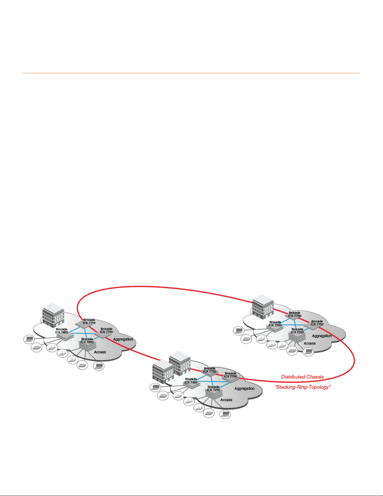
Certain fiber optic options increase the potential distance between stacks, which allows members of the same stack to reside in different
wiring closets, on different floors of one building, or in different buildings across the campus as illustrated in the following figure. Refer to
FastIron stacking distances and optics by device on page 21 for more information.
Brocade stackable devices are connected either through dedicated stacking ports or through ports that can be configured for either
stacking or data. The location of stacking ports and configuration options differ by device type. Refer to the section on each device type for
more information.
FIGURE 1 Distributed campus stacking topology
Ruckus FastIron Stacking Configuration Guide, 08.0.40b
Part Number: 53-1003910-11 15
Page 16

Stacking Overview
Campus Fabric
Network management and stack configuration
Even when all the switches within a stack are physically distributed, you can manage them as a single entity, enabling one-touch
configuration changes via a single IP address.
The active controller manages the other stack units. It maintains the information database for all stack members and downloads software
images as needed to all stack units. Each stack also has a standby controller for stack redundancy, and the stack can fail over seamlessly
to the standby.
Configuring the stack through the stack secure-setup utility is straightforward and secure. Custom configuration can be combined with
automated setup if, for example, you want to add units, move stacking ports, create trunks, or transform a default stacking port into a data
uplink port.
Switching and routing advantages
Packet switching between ports on stack units is handled by the hardware. All protocols operate with traditional stacking in the same way
as on a chassis system.
You can use stack connections to link distributed switches instead of standard inter-switch links with Layer 2 Spanning Tree Protocol (STP)
or Layer 3 routing. Using stack connections has significant advantages:
• Layer 2 simplicity. Stack links do not need to be considered as part of the overall network topology, which means that they can be
used to provide resiliency, and Layer 3 routing is not needed to manage traffic flows.
• No closed links. Because the stack links are internal to the switches, they are not seen as part of a Layer 2 network. This means
that all links can remain open and can be used to carry traffic simultaneously, maximizing throughput.
• Fast failover. The rapid detection and recovery techniques used on stack links mean that failure of a link or a switch results in
hitless failover, with no impact on user services.
The next section describes Switch Port Extender technology, which is based on an ICX 7750 core stack. Refer to the
Switch Port Extender Configuration Guide
for more information.
Brocade FastIron
Campus Fabric
Campus Fabric is sometimes referred to as Switch Port Extender (SPX).
Campus Fabric creates a more scalable architecture based on IEEE 802.1BR standards. Brocade Campus Fabric architecture adds
Brocade ICX 7450 or ICX 7250 devices configured as port extenders (PEs), or PE units, to a set of Brocade ICX 7750 stack units
configured as the control bridge. The ICX 7750 control bridge (CB) provides a single point of management for the extended network. Active
and standby controller functions are retained and continue to provide hitless recovery as well as extended administrative functions. Campus
Fabric greatly increases the number of access devices that the network can support. The distributed CB at the center of Campus Fabric
architecture manages PE units and hundreds to thousands of ports at the network edge.
PE units are standards-based devices. Typically lower in cost, PE units rely on the CB for most network functions. As the network expands,
new PE units can be detected and added to the network automatically using defined Campus Fabric communication protocols. PE units
also inherit Premium-license features from the CB, which further reduces cost.
Campus Fabric architecture simplifies network management by unifying core, aggregation, and access functions. As illustrated in the
following figure, a core stack (distributed chassis) serving as the CB connects to downstream Campus Fabric (PE) units that aggregate large
numbers of access devices.
16 Part Number: 53-1003910-11
Ruckus FastIron Stacking Configuration Guide, 08.0.40b
Page 17
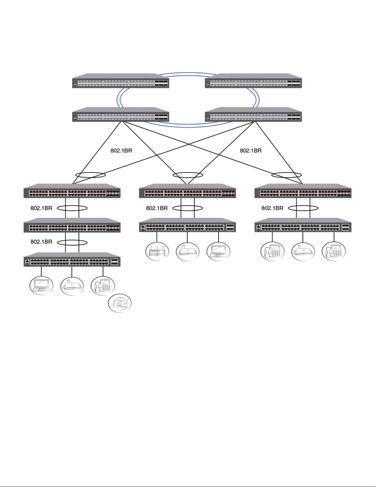
FIGURE 2 Campus Fabric domain build-out from an ICX 7750 CB stack
Stacking Overview
Campus Fabric
The following figure depicts three separate campuses, each with its own Campus Fabric domain, interconnected with a high-speed
backbone.
Ruckus FastIron Stacking Configuration Guide, 08.0.40b
Part Number: 53-1003910-11 17
Page 18

Stacking Overview
Brocade stackable models
FIGURE 3 Distributed campus network formed from connected Campus Fabric domains
Brocade stackable models
All ICX 7450 and ICX 7750 devices and some ICX 7250 devices can be members of a Brocade traditional stack. ICX 7750 devices installed
in a traditional stack can also be configured as an 802.1br control bridge that manages ICX 7450 devices configured as port extender (PE)
units. Refer to the
Refer to the following sections for information on the ICX 7250:
• ICX 7250 stacking topologies on page 46.
• ICX 7250 stack configuration overview on page 45.
Refer to the following sections for information on the ICX 7450:
• ICX 7450 stacking topologies on page 54.
• ICX 7450 stack configuration overview on page 53
• Planning to build a stack with 802.1br switch port extender capability on page 25.
Refer to the following sections for information on the ICX 7750:
• ICX 7750 stacking topologies on page 74.
• Configuring an ICX 7750 traditional stack on page 73
• Planning to build a stack with 802.1br switch port extender capability on page 25.
For information about physical installation of each type of device, refer to the appropriate hardware installation guide.
Brocade FastIron Switch Port Extender Configuration Guide
for information on 802.1br configuration.
18 Part Number: 53-1003910-11
Ruckus FastIron Stacking Configuration Guide, 08.0.40b
Page 19

Stacking Overview
Brocade traditional stacking terminology
Brocade traditional stacking terminology
Certain terms and roles specific to stacking are used throughout this guide. This section describes the roles stack units may assume as well
as terms key to understanding stacking.
NOTE
Refer to the
extender (SPX) capability.
Stack unit roles
• Active controller - Handles stack management and configures all system- and interface-level features.
– Future active controller - The unit that will take over as active controller after the next reload, if its priority has been changed to
• Standby controller - The stack member with the highest priority after the active controller. The standby controller takes over if the
current active controller fails.
• Stack member - A unit functioning in the stack in a capacity other than active controller or standby controller.
• Stack unit - Any device functioning within the stack, including the active controller and standby controller.
– Upstream stack unit - An upstream unit is connected to the first stacking port on the active controller. (The left port as you
– Downstream stack unit - A downstream unit is connected to the second stacking port on the active controller. (The right port
Brocade FastIron Switch Port Extender Configuration Guide
the highest priority. When a priority for a stack unit is changed to be higher than the existing active controller, the takeover
does not occur immediately to prevent disruptions in stack operation.
face the stacking ports.)
as you face the stacking ports.)
for terms specific to IEEE 802.1br and switch port
NOTE
The terms "upstream port" and "downstream port" have special meanings in an 802.1br SPX configuration. Refer to the
FastIron Switch Port Extender Configuration Guide
for more information.
Stacking terms
• Bootup role - The role a unit takes during the boot sequence. This role can be standalone, active controller, standby controller, or
stack member. The active controller or a standalone unit can access the full range of the CLI. Until a stack is formed, the local
consoles on the standby controller and stack members provide access to a limited form of the CLI, such as the show stack and a
few debug commands. When the stack is formed, all local consoles are directed to the active controller, which can access the
entire CLI. The last line of output from the show version command indicates the role of a unit (except for standalone units) as
shown in the following example:
My stack unit ID = 1, bootup role = active
• Clean unit - A unit that contains no startup flash configuration or runtime configuration. To erase old configuration information,
enter the erase startup-cong command and reset the unit.
• Control path - A path across stacking links dedicated to carrying control traffic such as commands to program hardware or
software image data for upgrades. A stack unit must join the control path to operate fully in the stack.
• Default ports - FastIron devices use the default-ports command to define stacking port candidates.
• Dynamic configuration - A unit configuration that is dynamically learned by a new stack unit from the active controller. A dynamic
configuration disappears when the unit leaves the stack.
• Interprocessor Communications (IPC) - The process by which proprietary packets are exchanged between stack unit CPUs.
Brocade
Ruckus FastIron Stacking Configuration Guide, 08.0.40b
Part Number: 53-1003910-11 19
Page 20

Stacking Overview
Brocade traditional stacking terminology
• IronStack - A set of Ruckus stackable units (maximum of twelve) and their connected stacking links so that all units can be
accessed through their common connections. A single unit can manage the entire stack, and configurable entities, such as VLANs
and trunk groups, can have members on multiple stack units.
• Non-Functioning stack unit - A stack unit that is recognized as a stack member, and is communicating with the active controller
over the Control Path, but is in a non-functioning state. A non-functioning stack unit will drop or discard traffic from non-stacked
ports. This may be caused by an image or configuration mismatch.
• Reserved / provisional unit - A unit configuration number that has no physical unit associated with it.
• Secure-setup - A software utility that establishes a secure stack.
• Sequential connection - Stack unit IDs, beginning with the active controller, are sequential. For example, 1, 3, 4, 6, 7 is sequential
if active controller is 1. 1, 7, 6, 4, 3 are non-sequential in a linear topology, but become sequential in a ring topology when counted
from the other direction as: 1, 3, 4, 6, 7. Gaps in numbering are allowed.
• Stack path - A data path formed across the stacking links to determine the set of stack members that are present in the stack
topology, and their locations in the stack.
• Stack slot - A
slot
in a stack is synonymous with a
line model
in a chassis.
• Stack topology - A contiguously-connected set of stack units in an IronStack that are currently communicating with each other. All
units that are present in the stack topology appear in output from the show stack command.
• Stacking link - A cable that connects a stacking port on one unit to a stacking port on another unit.
• Stacking port - A physical interface on a stack unit that connects a stacking link. Stacking ports are point-to-point links that
exchange proprietary packets. Stacking ports cannot be configured for any other purpose while operating as stacking ports. The
number of available stacking ports depends on the platform. Some ports can be configured as either stacking ports or regular
data ports. Refer to the hardware installation guide for the specific device for more information.
• Standalone unit - A unit that is not enabled for stacking, or an active controller without any standby controller or stack members.
• Static configuration - A configuration that remains in the database of the active controller even if the unit it refers to is removed
from the stack. Static configurations are derived from the startup configuration file during the boot sequence, are manually
entered, or are converted from dynamic configurations after a write memory command is issued.
• Trunked stacking port (trunk) - A trunk consists of multiple stacking ports and is treated as one logical link. It provides more
bandwidth and better resilience than individually connected ports.
• Unit replacement - The process of swapping out a unit with a clean unit. No configuration change is required.
20 Part Number: 53-1003910-11
Ruckus FastIron Stacking Configuration Guide, 08.0.40b
Page 21

Building a Stack
• Planning to build a traditional stack......................................................................................................................... 21
• Planning to build a stack with 802.1br switch port extender capability.....................................................................25
• Traditional stack construction methods....................................................................................................................26
• Verifying a traditional stack configuration................................................................................................................. 40
• Displaying information on stack connections........................................................................................................... 42
Planning to build a traditional stack
Before you begin to build a traditional stack, you should be familiar with supported stacking software requirements, topologies, and
recommendations.
Software requirements
All units in a traditional stack must be running the same software version.
Maximum configuration file size for any stack is 1 MB.
Traditional stack requirements
Traditional stacks must contain devices of the same type or product line. For example, a traditional stack cannot combine ICX 7250, ICX
7450, and ICX 7750 devices. However, a traditional stack can contain any combination of devices from the same product line, for example,
any combination of ICX 7250 devices.
NOTE
A core stack for an 802.1br (SPX) configuration is a traditional stack that contains only ICX 7750 devices, although the stack may
contain different types of ICX 7750 devices. Refer to the
information.
Brocade FastIron Campus Fabric Configuration Guide
for more
Brocade traditional stacking topologies
Brocade traditional stacking technology supports linear and ring topologies.
Although Brocade stackable units may be connected in a simple linear topology, Brocade recommends a ring topology because it offers the
best redundancy and the most resilient operation. Unicast switching follows the shortest path in a ring topology. When the ring is broken,
the stack recalculates the forwarding path and then resumes the flow of traffic within a few seconds.
In a ring topology, all stack members must have two stacking ports; however, in a linear topology, both end units use only one stacking
port, leaving the other port available as a data port.
FastIron stacking distances and optics by device
Because Brocade devices use Ethernet for the inter-switch stack connections, the deployment options are greatly increased. If standard
copper stacking cables are used, the inter-switch connections can be up to 5 meters, which is usually sufficient for locally distributed
stacks, such as in Top-of-Rack (ToR) applications. For broader distribution, fiber-optic cables should be used, allowing a stack to be
deployed across multiple physical locations, such as in the wiring closets of an office building, or in different buildings on a campus.
Ruckus FastIron Stacking Configuration Guide, 08.0.40b
Part Number: 53-1003910-11 21
Page 22

Building a Stack
Planning to build a traditional stack
Cables that support different distances can be combined in the same stack. For example, you can use LR4 Single Mode Fiber (SMF) optics
at both ends of a stacking connection, and the maximum distance is extended to 10 kilometers. Other stacking ports in the same stack can
use other optics, such as SR4, at both ends. The maximum distance for such a connection is 100 meters.
NOTE
The same optics (for example, LR4) must be used on both ends of a connection. If the optics do not match on both ends, the
ports will not come up.
The following table shows copper and fiber-optic options approved for stacking and stacking distance combinations. For more information
on Brocade cable options, refer to
The Brocade Optics Family Datasheet
on the Brocade website.
TABLE 5 Copper and fiber-optic options and stacking distances
Device Stacking port Copper options Fiber-optic options Fiber-optic maximum
stacking distance
ICX 7750 6 X 40-Gbps
Front and rear stacking
and uplink
ICX 7450 (rear) 1 X 40-Gbps stacking and
uplink on slots 3 and 4
ICX 7450 (front) 4 X 10-Gbps stacking on
slot 2 with the
icx7400-4x10GF module
only
ICX 7250 4 X 10-Gbps stacking
from dedicated or uplink
ports
4 X 10F SFP+ uplink ports:
No-PHY
4 X 10F SFP+ stacking
ports: With re-timer
capability
0.5- or 1-meter passive copper
1-, 3-, or 5-meter QSFP-QSFP
active direct-attach copper, 7 or 10meter QSFP-QSFP AOC
0.5- or 1-meter passive copper
3
1-, 3-, or 5-meter QSFP-QSFP
active direct-attach copper
1-, 3-, or 5-meter SFP+ active
direct-attach copper, 7 or 10-meter
SFP+ AOC
1-, 3-, or 5-meter active cables 10GE SR SFP+
40G-QSFP-SR4 100 meters
40G-QSFP-BiDi
40G-QSFP-eSR4 300 meters
40G-QSFP-LR4
40G-QSFP-LR4 10 kilometers
40G-QSFP-SR4 100 meters
40G-QSFP-eSR4 300 meters
10G-SFPP-USR 100 meters
10G-SFPP-SR 300 meters
10G-SFPP-LR 10 kilometers
10GE USR SFP+
10GE LR SFP+
1
10 kilometers for ICX
7750-26Q, ICX 7750-48C,
and ICX 7750-48F
2
devices
300 meters
100 meters
10 kilometers
Long-distance stacking ports
Only certain FastIron stacking devices support long-distance stacking. FastIron models and 40-Gbps ports that can be used for longdistance data and stacking connections are listed in the following table.
TABLE 6 FastIron long-distance 40-Gbps ports
Product and model Ports that support 1X40-Gbps optics Long-distance stacking ports
ICX 7450 (all models) 1/3/1, 1/4/1 1/3/1, 1/4/1
1
LR4 optics can be used only on specified ICX 7750 ports. Refer to "Long-distance stacking ports" in this guide.
2
Extended distance stacking on the ICX 7750 is restricted to certain ports. Refer to "Installing the ICX 7750 in a remote stack" in this guide.
3
For data uplink only, the following 40-Gbps optics are available on ICX 7450 devices: 40G-QSFP-BiDi, 40-G-QSFP-LM4, 40G-QSFP-ER4
22 Part Number: 53-1003910-11
Ruckus FastIron Stacking Configuration Guide, 08.0.40b
Page 23

Building a Stack
Planning to build a traditional stack
TABLE 6 FastIron long-distance 40-Gbps ports (continued)
Product and model Ports that support 1X40-Gbps optics Long-distance stacking ports
ICX 7750-26Q 1/1/1 through 1/1/20; 1/2/1 through 1/2/6, 1/3/5, 1/3/6 1/2/5, 1/2/6, 1/3/5, 1/3/6
ICX 7750-48F 1/2/5, 1/2/6, 1/3/5, 1/3/6 1/2/5, 1/2/6, 1/3/5, 1/3/6
ICX 7750-48C 1/2/5, 1/2/6, 1/3/5, 1/3/6 1/2/5, 1/2/6, 1/3/5, 1/3/6
NOTE
Long-distance stacking ports are not default stacking ports. If you are using only long-distance stacking ports, you cannot use the
stack secure-setup utility to configure your stack because the secure-setup utility probes for other potential stack members only
on default stacking ports.
LR optics can be used on ICX 7450 4X10-Gbps ports when a 4X10GF module is installed. LR optics can support distances up to 10
kilometers for data or stacking. Long-distance stacking with LR optics is supported on front panel ports 1/2/1 through 1/2/4. The following
table summarizes LR support on the ICX 7450.
TABLE 7 FastIron long-distance 4X10-Gbps ports
Product and model 10-Gbps ports that support LR optics Long-distance stacking ports
ICX 7450 front (all models, with 4X10GF
module)
ICX 7450 back (all models, with 4X10GF
module)
1/2/1 through 1/2/4 1/2/1 through 1/2/4
1/3/1 through 1/3/4 and 1/4/1 through 1/4/4 (data only) 1/3/1 through 1/3/4 and 1/4/1 through
1/4/4
For general information on all long-distance stacking options for all FastIron stacking models, refer to FastIron stacking distances and optics
by device on page 21. For details on setting up for long-distance stacking, refer to Installing the ICX 7750 in a remote stack on page 78.
Displaying information on supported distances
Use the show media command to display information on stacking connections and supported distances. You can specify any interface
within a stack or SPX configuration as shown in the following examples. You can also designate a stack to display all media attached to the
stack. Without parameters, the command displays all media attached to the device.
The following example displays information for an interface with an LR4 optic.
ICX7750-48F Router# show media ethernet 4/2/6
Port 4/2/6: Type : 40GE-LR4 10km (QSFP+ LC)
Vendor: BROCADE Version: 2
Part# : 57-1000263-01 Serial#: LDJ21325C230002
The following command output is for an interface with a 40-Gbps active copper optic with a maximum distance of 10 meters.
ICX7750-48F Switch# show media ethernet 3/2/1
Port 3/2/1: Type : 40GE-Active Copper 10m (QSFP+)
Vendor: BROCADE Version: A
Part# : 57-1000306-01 Serial#: NEA11510000003S
The following output is for an interface with a 40-Gbps ESR4 optic.
ICX7750-48F Switch# show media ethernet 1/2/3
Port 1/2/3: Type : 40GE-ESR4 300m (QSFP+)
Vendor: BROCADE Version: A
Part# : 57-1000296-01 Serial#: LVA115150000004
The following example displays information about the media attached to the device.
device# show media
Port 1/1/1 : Type : 1G M-C (Gig-Copper)
Ruckus FastIron Stacking Configuration Guide, 08.0.40b
Part Number: 53-1003910-11 23
Page 24

Building a Stack
Planning to build a traditional stack
Port 1/1/2 : Type : 1G M-C (Gig-Copper)
Port 1/1/3 : Type : 1G M-C (Gig-Copper)
Port 1/1/4 : Type : 1G M-C (Gig-Copper)
Port 1/1/5 : Type : 1G M-C (Gig-Copper)
Port 1/1/6 : Type : 1G M-C (Gig-Copper)
Port 1/1/7 : Type : 1G M-C (Gig-Copper)
Port 1/1/8 : Type : 1G M-C (Gig-Copper)
Port 1/1/9 : Type : 1G M-C (Gig-Copper)
Port 1/1/10: Type : 1G M-C (Gig-Copper)
Port 1/1/11: Type : 1G M-C (Gig-Copper)
Port 1/1/12: Type : 1G M-C (Gig-Copper)
Port 1/1/13: Type : 1G M-C (Gig-Copper)
Port 1/1/14: Type : 1G M-C (Gig-Copper)
Port 1/1/15: Type : 1G M-C (Gig-Copper)
Port 1/1/16: Type : 1G M-C (Gig-Copper)
Port 1/1/17: Type : 1G M-C (Gig-Copper)
Port 1/1/18: Type : 1G M-C (Gig-Copper)
Port 1/1/19: Type : 1G M-C (Gig-Copper)
Port 1/1/20: Type : 1G M-C (Gig-Copper)
Port 1/1/21: Type : 1G M-C (Gig-Copper)
Port 1/1/22: Type : 1G M-C (Gig-Copper)
Port 1/1/23: Type : 1G M-C (Gig-Copper)
Port 1/1/24: Type : 1G M-C (Gig-Copper)
Port 1/2/1 : Type : 10GE SR 300m (SFP +)
Port 1/2/2 : Type : EMPTY
Port 1/2/3 : Type : 1G Twinax 1m (SFP)
Port 1/2/4 : Type : 1G Twinax 1m (SFP)
The following example shows output for the specified stack.
device# show media stack 1
Port 1/1/1 : Type : EMPTY
Port 1/1/2 : Type : EMPTY
Port 1/1/3 : Type : EMPTY
Port 1/1/4 : Type : EMPTY
Port 1/1/5 : Type : EMPTY
Port 1/1/6 : Type : EMPTY
Port 1/1/7 : Type : EMPTY
Port 1/1/8 : Type : EMPTY
Port 1/1/9:1 : Type : 4x10GE Active Copper 1m (QSFP+)
Port 1/1/9:2 : Type : 4x10GE Active Copper 1m (QSFP+)
Port 1/1/9:3 : Type : 4x10GE Active Copper 1m (QSFP+)
Port 1/1/9:4 : Type : 4x10GE Active Copper 1m (QSFP+)
Port 1/1/10 : Type : EMPTY
Port 1/1/11:1: Type : 4x10GE Active Copper 1m (QSFP+)
Port 1/1/11:2: Type : 4x10GE Active Copper 1m (QSFP+)
Port 1/1/11:3: Type : 4x10GE Active Copper 1m (QSFP+)
Port 1/1/11:4: Type : 4x10GE Active Copper 1m (QSFP+)
Port 1/1/12 : Type : EMPTY
Port 1/1/13 : Type : EMPTY
Port 1/1/14 : Type : EMPTY
Port 1/1/15 : Type : EMPTY
Port 1/1/16 : Type : EMPTY
Port 1/1/17 : Type : EMPTY
Port 1/1/18 : Type : EMPTY
Port 1/1/19 : Type : EMPTY
Port 1/1/20 : Type : EMPTY
Port 1/2/1 : Type : EMPTY
Port 1/2/2 : Type : EMPTY
Port 1/2/3 : Type : EMPTY
Port 1/2/4 : Type : EMPTY
Port 1/2/5 : Type : EMPTY
Port 1/2/6 : Type : EMPTY
Port 1/3/1 : Type : 40GE-SR4 100m (QSFP+)
Port 1/3/2 : Type : EMPTY
Port 1/3/3 : Type : EMPTY
Port 1/3/4 : Type : EMPTY
Port 1/3/5 : Type : EMPTY
Port 1/3/6 : Type : EMPTY
24 Part Number: 53-1003910-11
Ruckus FastIron Stacking Configuration Guide, 08.0.40b
Page 25

Building a Stack
Planning to build a stack with 802.1br switch port extender capability
Traditional stacking configuration guidelines
Before you configure your traditional stack, consider the following guidelines:
• Plan the number of units and how the stacking ports on the units will be connected. For more information, refer to the hardware
installation guide for your device.
• The stack should be physically cabled in a linear or ring topology. Connect only those units that will be active in the stack.
• Make sure all units intended for the stack are running the same software version. On any of the console ports in the stack, use the
show version command to view all units, or the show version unit
NOTE
If you are running a router image and there is a potential loop in your topology, you must configure the Spanning Tree Protocol in
the would-be active controller. Otherwise, excessive looping packets may affect stack formation. The Spanning Tree Protocol is
enabled by default in switch images.
NOTE
If STP is not enabled, there may be a loop issue when multiple cables are used to connect a standalone unit to a stack. The loop
does not affect stack formation. The loop issue disappears after the multiple links are converted to stacking trunks when the
standalone unit is integrated to the stack. However, temporary looping may cause some data traffic interruption. If you are
concerned about potential traffic interruption due to looping, you can connect a single cable to the new unit. After the unit reloads
and becomes a member, you can connect all cables and then run the stack secure-setup utility to make sure these links are
converted to stacking trunks.
unit-number
command to view an individual unit.
• When you have a stack of eight or more units, you may need to increase the trap hold time from the default (60 seconds) to five
minutes (300 seconds). This will prevent the loss of initial boot traps. To increase the trap hold time, use the following command.
device# configure terminal
device(config)# snmp-server enable traps holddown-time 300
Planning to build a stack with 802.1br switch port
extender capability
If you are planning to create an 802.1br SPX configuration with an ICX 7750 core stack, there are a few considerations.
In general, Brocade traditional stacking and 802.1br SPX configuration are independent. Here are a few details to keep in mind:
• Only ICX 7750 devices can serve as the control bridge (CB). The CB can be a standalone unit or a stack of multiple units.
• Only ICX 7450 devices can be configured as PE units attached to the CB. PE units can be attached to any CB unit.
• While a traditional stack may include up to 12 units, a CB stack of no more than four units is recommended.
• ICX 7750 breakout ports can be used with an 802.1br SPX configuration; however, they can be enabled only in a standalone ICX
7750 unit.
• SPX runs over LLDP protocol at Layer 2. When you enable SPX with the spx cb-enable command, the lldp run command is also
executed if LLDP has not previously been enabled.
• You will need to plan a server location from which images and manifest files can be downloaded to PE units.
• In general, ICX 7750 devices in the CB retain all capabilities. The feature set of ICX 7450 devices operating as PE units, however,
may be affected.
For detailed information on 802.1br SPX configuration, including protocol considerations, refer to the
Extender Configuration Guide
Ruckus FastIron Stacking Configuration Guide, 08.0.40b
Part Number: 53-1003910-11 25
.
Brocade FastIron Switch Port
Page 26

Building a Stack
Traditional stack construction methods
Traditional stack construction methods
NOTE
The principles outlined in stack construction scenarios apply to all ICX devices. Figures used to illustrate a certain stack topology
are not necessarily representative of other devices. For illustrations specific to a particular device, refer to the stack configuration
section for that device, which also contains device-specific stacking considerations and configuration examples.
There are three ways to build a traditional stack.
1. The secure-setup utility. Secure-setup gives you control over the design of your stack topology and provides security through
password verification. For the secure-setup procedure, refer to Using secure-setup to configure a traditional stack in a ring
topology on page 27.
2. Automatic stack configuration. With this method, you enter all configuration information, including the module type and the
priorities of all members into the unit you decide will be the active controller and set its priority to be the highest. When you enable
stacking on the active controller, the stack then forms automatically. This method requires that you start with clean units (except for
the active controller) that do not contain startup or runtime configurations. Refer to Scenario 2 - Automatically configuring a three-
member traditional stack in a ring topology on page 35.
3. Manual stack configuration. With this method, you configure every unit individually and enable stacking on each unit. Once the
units are connected together, they automatically operate as a traditional stack. With this method, the unit with the highest priority
becomes the active controller, and ID assignment is determined by the sequence in which you physically connect the units. Refer
to Scenario 3 - Manually configuring a three member traditional stack in a ring topology on page 39.
The secure-setup utility
NOTE
Secure-setup works for units within a single stack. It does not work across stacks.
NOTE
Long distance stacking ports are not default stacking ports. If you are using only long distance stacking ports, you cannot use the
stack secure-setup utility to configure your stack because the secure-setup utility probes for other potential stack members only
on default stacking ports.
Secure-setup lets you easily configure your entire stack through the active controller, which propagates the configuration to all stack
members. Secure-setup is the most secure way to build a traditional stack. It gives you the most control over how your stack is built. For
example, secure-setup offers three security features that prevent unauthorized devices from accessing or joining a traditional stack:
• Authentication of secure-setup packets provides verification that these packets are from a genuine Ruckus stack unit. MD5-based
port verification confirms stacking ports.
• A superuser password is required to allow password-protected devices to become members of a traditional stack.
• The stack disable command prevents a unit from listening for or sending stacking packets. When a unit is stack-disabled, no
other device in the network can force the unit to join a traditional stack.
Secure-setup can also be used to add units to an existing traditional stack and to change the stack IDs of stack members.
Secure-setup and the active controller
When secure-setup is issued on a unit that is not already the active controller, the unit becomes the active controller. If this unit does not
already have an assigned priority and if no other unit in the stack has a priority higher than 128, secure-setup assigns the unit a priority of
128 by default. However, if another unit in the stack has a priority of 128 or higher, secure-setup gives the active controller a priority equal to
the highest priority unit in the stack (which is by default the standby controller). When the active controller and the standby controller have
26 Part Number: 53-1003910-11
Ruckus FastIron Stacking Configuration Guide, 08.0.40b
Page 27
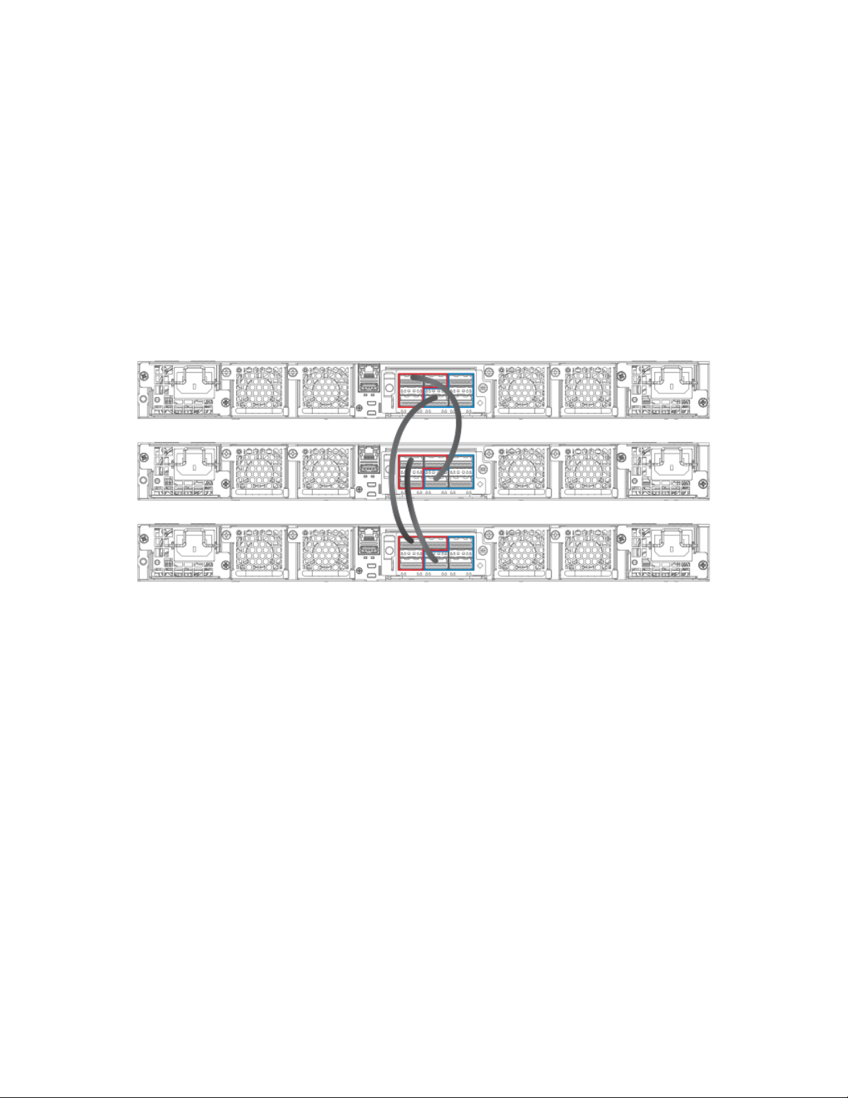
Building a Stack
Traditional stack construction methods
identical priorities, during a reset, the old active controller cannot reassume its role from the standby controller (which became the active
controller at the reset).
If the previous active controller again becomes active and you want it to resume the role of active controller, you should set the priority for
the standby controller to a priority lower than 128. If you do not want the previous active controller to remain the active controller, you can
set the same priority for both active and standby controllers (equal to or higher than128).
Using secure-setup to configure a traditional stack in a ring topology
The following figure shows three ICX 7750 stacking units connected in a ring. The secure-setup example that follows is for 12 ICX 7750
units in a ring topology. However, the procedure can be used for any stackable ICX device and any size traditional stack.
FIGURE 4 Traditional stack with ring topology
1. Connect the devices using the stacking ports and stack cabling. For more information, refer to the appropriate hardware
installation guides.
2. Power on the units.
3. Connect your console to the intended active controller. The unit through which you run secure-setup becomes the active controller
by default.
4. Issue the stack enable command on the intended active controller.
device# configure terminal
device(config)# stack enable
device(config)# exit
Ruckus FastIron Stacking Configuration Guide, 08.0.40b
Part Number: 53-1003910-11 27
Page 28

Building a Stack
Traditional stack construction methods
5. Enter the stack secure-setup command. As shown in the following example, this command triggers a Ruckus proprietary
discovery protocol that begins the discovery process in both upstream and downstream directions. The discovery process
produces a list of upstream and downstream devices that are available to join the stack. Secure-setup can detect up to 11 units in
each direction (22 units total); however, you must select a total number of units that is less than the maximum stack size for the
device because the controller is also part of the stack.
NOTE
During the secure-setup process, after one minute of inactivity, authentication for stack members expires, forcing you to
restart the process.
NOTE
To exit the secure-setup, enter ^C at any time.
The following example shows the suggested discovered topology.
ICX7750-48F Router# stack secure-setup
ICX7750-48F Router# Discovering the stack topology...
Current Discovered Topology - RING
Available UPSTREAM units
Hop(s) Id Type Mac Address
1 new ICX7750-48XGF cc4e.246d.8d80
2 new ICX7750-48XGF cc4e.246d.9b00
3 new ICX7750-48XGF cc4e.246d.9c80
4 new ICX7750-20QXG cc4e.2439.2a80
5 new ICX7750-20QXG cc4e.2439.3700
6 new ICX7750-20QXG cc4e.2439.3880
7 new ICX7750-20QXG cc4e.2439.2d00
8 new ICX7750-48XGC cc4e.2439.1a00
9 new ICX7750-48XGC cc4e.2439.1680
10 new ICX7750-48XGC cc4e.2439.1d80
11 new ICX7750-48XGC cc4e.2439.1280
Available DOWNSTREAM units
Hop(s) Id Type Mac Address
1 new ICX7750-48XGC cc4e.2439.1280
2 new ICX7750-48XGC cc4e.2439.1d80
3 new ICX7750-48XGC cc4e.2439.1680
4 new ICX7750-48XGC cc4e.2439.1a00
5 new ICX7750-20QXG cc4e.2439.2d00
6 new ICX7750-20QXG cc4e.2439.3880
7 new ICX7750-20QXG cc4e.2439.3700
8 new ICX7750-20QXG cc4e.2439.2a80
9 new ICX7750-48XGF cc4e.246d.9c80
10 new ICX7750-48XGF cc4e.246d.9b00
11 new ICX7750-48XGF cc4e.246d.8d80
Do you accept the topology (RING) (y/n)?: y
You are prompted to accept the topology.
28 Part Number: 53-1003910-11
Ruckus FastIron Stacking Configuration Guide, 08.0.40b
Page 29

6. Enter y to accept the topology. You should see output similar to the following.
Selected Topology:
Active Id Type Mac Address
1 ICX7750-48XGF cc4e.246d.9e00
Selected UPSTREAM units
Hop(s) Id Type Mac Address
1 2 ICX7750-48XGF cc4e.246d.8d80
2 3 ICX7750-48XGF cc4e.246d.9b00
3 4 ICX7750-48XGF cc4e.246d.9c80
4 5 ICX7750-20QXG cc4e.2439.2a80
5 6 ICX7750-20QXG cc4e.2439.3700
6 7 ICX7750-20QXG cc4e.2439.3880
7 8 ICX7750-20QXG cc4e.2439.2d00
8 9 ICX7750-48XGC cc4e.2439.1a00
9 10 ICX7750-48XGC cc4e.2439.1680
10 11 ICX7750-48XGC cc4e.2439.1d80
11 12 ICX7750-48XGC cc4e.2439.1280
Selected DOWNSTREAM units
Hop(s) Id Type Mac Address
1 12 ICX7750-48XGC cc4e.2439.1280
2 11 ICX7750-48XGC cc4e.2439.1d80
3 10 ICX7750-48XGC cc4e.2439.1680
4 9 ICX7750-48XGC cc4e.2439.1a00
5 8 ICX7750-20QXG cc4e.2439.2d00
6 7 ICX7750-20QXG cc4e.2439.3880
7 6 ICX7750-20QXG cc4e.2439.3700
8 5 ICX7750-20QXG cc4e.2439.2a80
9 4 ICX7750-48XGF cc4e.246d.9c80
10 3 ICX7750-48XGF cc4e.246d.9b00
11 2 ICX7750-48XGF cc4e.246d.8d80
Building a Stack
Traditional stack construction methods
Ruckus FastIron Stacking Configuration Guide, 08.0.40b
Part Number: 53-1003910-11 29
Page 30

Building a Stack
Traditional stack construction methods
7. If the Brocade device supports stacking trunks, the system next displays available trunk options in turn and requests your input on
how many ports to include. The range is presented in parentheses, and the current setting is presented in square brackets. For
example, (1-3) [ 1 ] indicates that the current connection is a single-port link, and you have the option of electing a 2-port or a 3-
port trunk instead. When prompted, enter the desired trunk size as shown in the following example.
Confirm Stacking Links...
UPSTREAM Unit: Id new at 4 hop(s) ICX7750-20QXG cc4e.2439.2a80
Enter the desired links(1-3)[1]: 3
UPSTREAM Unit: Id new at 6 hop(s) ICX7750-20QXG cc4e.2439.3880
Enter the desired links(1-3)[1]: 3
UPSTREAM Unit: Id new at 10 hop(s) ICX7750-48XGC cc4e.2439.1d80
Enter the desired links(1-2)[1]: 2
UPSTREAM Unit: Id new at 11 hop(s) ICX7750-48XGC cc4e.2439.1280
Enter the desired links(1-2)[1]: 2
Once you have specified trunk sizes, you should see system output similar to the following example, and you are prompted to
confirm the stack unit IDs.
Selected Topology:
Active Id Type Mac Address
1 ICX7750-48XGF cc4e.246d.9e00
Selected UPSTREAM units
Hop(s) Id Type Mac Address
1 2 ICX7750-48XGF cc4e.246d.8d80
2 3 ICX7750-48XGF cc4e.246d.9b00
3 4 ICX7750-48XGF cc4e.246d.9c80
4 5 ICX7750-20QXG cc4e.2439.2a80
5 6 ICX7750-20QXG cc4e.2439.3700
6 7 ICX7750-20QXG cc4e.2439.3880
7 8 ICX7750-20QXG cc4e.2439.2d00
8 9 ICX7750-48XGC cc4e.2439.1a00
9 10 ICX7750-48XGC cc4e.2439.1680
10 11 ICX7750-48XGC cc4e.2439.1d80
11 12 ICX7750-48XGC cc4e.2439.1280
Selected DOWNSTREAM units
Hop(s) Id Type Mac Address
1 12 ICX7750-48XGC cc4e.2439.1280
2 11 ICX7750-48XGC cc4e.2439.1d80
3 10 ICX7750-48XGC cc4e.2439.1680
4 9 ICX7750-48XGC cc4e.2439.1a00
5 8 ICX7750-20QXG cc4e.2439.2d00
6 7 ICX7750-20QXG cc4e.2439.3880
7 6 ICX7750-20QXG cc4e.2439.3700
8 5 ICX7750-20QXG cc4e.2439.2a80
9 4 ICX7750-48XGF cc4e.246d.9c80
10 3 ICX7750-48XGF cc4e.246d.9b00
11 2 ICX7750-48XGF cc4e.246d.8d80
Do you accept the unit id's (y/n)?: y
30 Part Number: 53-1003910-11
Ruckus FastIron Stacking Configuration Guide, 08.0.40b
Page 31

Building a Stack
Traditional stack construction methods
8. Review the topology and the unit IDs that are displayed. When prompted, enter y if you want to accept the assigned unit IDs.
NOTE
You can also enter n to decline the assigned unit IDs. The system then prompts you to enter different IDs, warns that
changing the unit IDs manually may modify stack configuration, and recommends that you save the configuration and
reload it after the stack is ready.
9. The active controller automatically checks all prospective stack members to see if they are password-protected. If a unit is
password- protected, enter the password before you to add the unit. If you do not know the password, take one of the following
actions:
• Discontinue secure-setup by entering ^C.
• Obtain the device password from the administrator.
• Skip this unit and continue the secure-setup for your stack. The password-protected device and all devices connected behind
it will not be included in the setup process.
In the following example, the second unit is password-protected, so you are asked for the password.
device# stack secure-setup
device# Discovering the stack topology...
Verifying password for the password protected units...
Found UPSTREAM units
Hop(s) Id Type MAC Address
1 2 ICX7750-48XGF cc4e.246d.8d80
2 3 ICX7750-48XGF cc4e.246d.9b00
Enter password for ICX7750-48XGF located at 2 hop(s): ****
Enter the number of the desired UPSTREAM units (1-2)[1]: 2
Selected Topology:
Active Id Type MAC Address
1 ICX7750-48XGF cc4e.246d.9e00
Selected UPSTREAM units
Hop(s) Id Type MAC Address
1 2 ICX7750-48XGF cc4e.246d.8d80
2 3 ICX7750-48XGF cc4e.246d.9b00
Do you accept the unit id's (y/n)?: y
Ruckus FastIron Stacking Configuration Guide, 08.0.40b
Part Number: 53-1003910-11 31
Page 32

Building a Stack
Traditional stack construction methods
10. Enter y to accept these recommendations, or enter n to reject the recommendations.
NOTE
You can use secure-setup to renumber the units in your stack. Refer to Renumbering stack units on page 131.
After you accept the unit IDs, an active controller is elected, the stack is formed, and a standby controller is designated. You
should see output similar to the following example.
ICX7750-48F Router#T=18m45.7: Election, was alone --> active, ID=1, pri=128,
12U(1-12), A=u1, nbr#=11 11, reason: u6: SecureS, ,
T=18m49.7: Election, was active, no change, ID=1, pri=128, 12U(1-12), A=u1,
nbr#=11 11, reason: u1: stk-po-chg, ,
T=18m52.3: reset unit 2: u2 bo-id=1
T=18m52.3: reset unit 3: u3 bo-id=1
T=18m52.3: reset unit 5: u5 bo-id=1
T=18m52.3: reset unit 6: u6 bo-id=1
T=18m52.3: reset unit 7: u7 bo-id=1
T=18m52.3: reset unit 8: u8 bo-id=1
T=18m52.3: reset unit 9: u9 bo-id=1
T=18m52.3: reset unit 10: u10 bo-id=1
T=18m52.3: reset unit 11: u11 bo-id=1
T=18m52.3: reset unit 12: u12 bo-id=1
Reset extra units due to path: 4
Config changed due to add/del units. Do write mem if you want to keep it
T=18m55.3: Unit 1 loses all neighbors.
T=18m55.4: Active U1 deletes U2 and its config because it is learned.
T=18m55.6: Active U1 deletes U3 and its config because it is learned.
T=18m55.8: Active U1 deletes U4 and its config because it is learned.
T=18m55.9: Active U1 deletes U5 and its config because it is learned.
T=18m56.0: Active U1 deletes U6 and its config because it is learned.
T=18m56.1: Active U1 deletes U7 and its config because it is learned.
T=18m56.2: Active U1 deletes U8 and its config because it is learned.
T=18m56.3: Active U1 deletes U9 and its config because it is learned.
T=18m56.4: Active U1 deletes U10 and its config because it is learned.
T=18m56.6: Active U1 deletes U11 and its config because it is learned.
T=18m56.7: Active U1 deletes U12 and its config because it is learned.
ICX7750-48F Router# T=19m55.7: Election, was active, no change, ID=1, pri=128,
3U(1-3), A=u1, nbr#=2 0, reason: u3: port-dw, ,
T=19m55.8: Synchronize webauth files to u2
T=19m55.8: Synchronize webauth files to u3
T:19m57.1: Done hot swap: active controller u1 sets u2 to Ready.
T:19m57.1: Done hot swap: active controller u1 sets u3 to Ready.
Config changed due to add/del units. Do write mem if you want to keep it
Stack unit 2 Power supply 1 is up
Stack unit 2 Power supply 2 is down
Stack unit 3 Power supply 1 is up
Stack unit 3 Power supply 2 is down
T=20m2.4: Election, was active, no change, ID=1, pri=128, 3U(1-3), A=u1, nbr#=2 0,
reason: u1: port-up, ,
T=20m3.6: 1/2/4 goes down. delete direction 1, trigger election
T=20m7.3: Election, was active, no change, ID=1, pri=128, 12U(1-12), A=u1,
nbr#=11 11, reason: u12: port-up, ,
T=20m7.6: Synchronize webauth files to u10
T=20m7.6: Synchronize webauth files to u11
Detect stack unit 12 has different startup config flash, will synchronize it
T=20m7.6: Synchronize webauth files to u12
Detect stack unit 4 has different startup config flash, will synchronize it
T=20m7.6: Synchronize webauth files to u4
T=20m7.6: Synchronize webauth files to u5
T=20m7.6: Synchronize webauth files to u6
T=20m7.6: Synchronize webauth files to u7
T=20m7.7: Synchronize webauth files to u8
T=20m8.3: Synchronize webauth files to u9
T:20m8.8: Done hot swap: active controller u1 sets u10 to Ready.
T:20m9.0: Done hot swap: active controller u1 sets u11 to Ready.
T:20m9.3: Done hot swap: active controller u1 sets u12 to Ready.
T:20m9.9: Done hot swap: active controller u1 sets u4 to Ready.
32 Part Number: 53-1003910-11
Ruckus FastIron Stacking Configuration Guide, 08.0.40b
Page 33

Traditional stack construction methods
T:20m10.2: Done hot swap: active controller u1 sets u5 to Ready.
T:20m10.5: Done hot swap: active controller u1 sets u6 to Ready.
T:20m10.9: Done hot swap: active controller u1 sets u7 to Ready.
T:20m11.4: Done hot swap: active controller u1 sets u8 to Ready.
Stack unit 12 Power supply 1 is up
Stack unit 12 Power supply 2 is down
Stack unit 10 Power supply 1 is up
Stack unit 10 Power supply 2 is down
Config changed due to add/del units. Do write mem if you want to keep it
T:20m13.1: Done hot swap: active controller u1 sets u9 to Ready.
T=20m16.9: Election, was active, no change, ID=1, pri=128, 12U(1-12), A=u1,
nbr#=11 11, reason: u1: stk-po-chg, ,
Config changed due to add/del units. Do write mem if you want to keep it
ICX7750-48F Router#T=21m16.9: Assigned unit 2 to be standby
cT=21m18.9: start running config sync to standby u2
T=21m19.3: Running config sync to standby u2 is complete
11. Enter the show stack command to verify that all units are in the ready state.
The following show stack command output shows the resulting 12-unit ICX 7750 ring topology. All units are ready.
ICX7750-48F Router# show stack
T=23m12.5: alone: standalone, D: dynamic cfg, S: static, A=10, B=11, C=12
ID Type Role Mac Address Pri State Comment
1 S ICX7750-48XGF active cc4e.246d.9e00 128 local Ready
2 D ICX7750-48XGF standby cc4e.246d.8d80 0 remote Ready
3 D ICX7750-48XGF member cc4e.246d.9b00 0 remote Ready
4 D ICX7750-48XGF member cc4e.246d.9c80 0 remote Ready
5 D ICX7750-20QXG member cc4e.2439.2a80 0 remote Ready
6 D ICX7750-20QXG member cc4e.2439.3700 0 remote Ready
7 D ICX7750-20QXG member cc4e.2439.3880 0 remote Ready
8 D ICX7750-20QXG member cc4e.2439.2d00 0 remote Ready
9 D ICX7750-48XGC member cc4e.2439.1a00 0 remote Ready
10 D ICX7750-48XGC member cc4e.2439.1680 0 remote Ready
11 D ICX7750-48XGC member cc4e.2439.1d80 0 remote Ready
12 D ICX7750-48XGC member cc4e.2439.1280 0 remote Ready
Building a Stack
active
+---+ +---+ +---+ +---+ +---+ +---+
-2/1| 1 |2/4--2/1| C |2/4==2/1| B |2/4==2/1| A |2/4--2/1| 9 |2/4--2/1| 8 |2/4 | +---+ +---+ +---+ +---+ +---+ +---+ |
| |
| standby |
| +---+ +---+ +---+ +---+ +---+ +---+ |
-2/4| 2 |2/1--2/4| 3 |2/1--2/4| 4 |2/1==2/4| 5 |2/1--2/4| 6 |2/1==2/4| 7 |2/1 +---+ +---+ +---+ +---+ +---+ +---+
Standby u2 - protocols ready, can failover
Current stack management MAC is cc4e.246d.9e00
For ICX devices, an equal sign (=) is used to indicate connections between trunk ports as shown in the previous example.
NOTE
In the previous example, D indicates a dynamic configuration. After you perform a write memory, the D changes to an
S, for static configuration.
Ruckus FastIron Stacking Configuration Guide, 08.0.40b
Part Number: 53-1003910-11 33
Page 34

Building a Stack
Traditional stack construction methods
12. If you need additional information on individual ports, enter the show stack stack-ports command as shown in the following
example.
device# show stack stack-ports
active
+-+ +-+ +-+ +-+ +-+ +-+
=2/1|4|2/6==2/6|3|2/1==2/1|2|2/6==2/6|1|2/1==2/1|7|2/6==2/6|6|2/1=
| +-+ +-+ +-+ +-+ +-+ +-+ |
| |
| standby |
| +-+ |
--------------------------------------------------------2/1|5|2/6=
+-+
U# Stack-port1 Stack-port2
1 up (1/2/1-1/2/5) up (1/2/6-1/2/10)
up ports: 1/2/1, 1/2/2, 1/2/3, 1/2/4, 1/2/5
U# Stack-port1 Stack-port2
1 up (1/2/1-1/2/5) up (1/2/6-1/2/10)
up ports: 1/2/1, 1/2/2, 1/2/3, 1/2/4, 1/2/5
up ports: 1/2/6, 1/2/7, 1/2/8, 1/2/9, 1/2/10
2 up (2/2/1-2/2/5) up (2/2/6-2/2/10)
up ports: 2/2/1, 2/2/2, 2/2/3, 2/2/4, 2/2/5
up ports: 2/2/6, 2/2/7, 2/2/8, 2/2/9, 2/2/10
3 up (3/2/1-3/2/5) up (3/2/6-3/2/10)
up ports: 3/2/1, 3/2/2, 3/2/3, 3/2/4, 3/2/5
up ports: 3/2/6, 3/2/7, 3/2/8, 3/2/9, 3/2/10
4 up (4/2/1-4/2/5) up (4/2/6-4/2/10)
up ports: 4/2/1, 4/2/2, 4/2/3, 4/2/4, 4/2/5
up ports: 4/2/6, 4/2/7, 4/2/8, 4/2/9, 4/2/10
5 up (5/2/1-5/2/5) up (5/2/6-5/2/10)
up ports: 5/2/1, 5/2/2, 5/2/3, 5/2/4, 5/2/5
up ports: 5/2/6, 5/2/7, 5/2/8, 5/2/9, 5/2/10
6 up (6/2/1-6/2/5) up (6/2/6-6/2/10)
up ports: 6/2/1, 6/2/2, 6/2/3, 6/2/4, 6/2/5
up ports: 6/2/6, 6/2/7, 6/2/8, 6/2/9, 6/2/10
7 up (7/2/1-7/2/5) up (7/2/6-7/2/10)
up ports: 7/2/1, 7/2/2, 7/2/3, 7/2/4, 7/2/5
up ports: 7/2/6, 7/2/7, 7/2/8, 7/2/9, 7/2/10
13. Once all of the stack units are active, enter the write memory command on the active controller. This command initiates
configuration synchronization, which copies the configuration file of the active controller to the rest of the stack units.
NOTE
The secure-setup process may modify your configuration with information about new units, stacking ports, and so on.
For this reason, it is very important to save this information by issuing the write memory command. If you do not do
this, you may lose your configuration information the next time the stack reboots.
The secure-setup process for your stack is now complete.
Invalid stacking trunk errors and network loops
Invalid stacking trunk errors are displayed when stack ports have been assigned incorrectly or do not match physical connections, or when
trunk connections are incorrect.
NOTE
You can verify the connections for each unit based on the MAC address.
When connecting a standalone unit to a stack using data ports, be sure to issue the stack disable command first on the standalone unit
before using the secure-setup utility to add the unit. Otherwise, the secure-setup utility will issue an invalid stacking trunk error and will not
be able to discover the unit.
34 Part Number: 53-1003910-11
Ruckus FastIron Stacking Configuration Guide, 08.0.40b
Page 35

Building a Stack
Traditional stack construction methods
When incorrect connections are detected, the secure-setup utility displays a message similar to the following.
ICX7750-48F Router# stack secure-setup
ICX7750-48F Router# Discovering the stack topology...
Invalid Stacking Trunk connection at Unit with mac cc4e.2439.1280, port 1/3/5
Please check connection and then re-try...
ICX7750-48F Router#
If a stack is incorrectly constructed and contains loop connections, secure-setup cannot be performed. A message similar to the following
is displayed when this occurs.
ICX7750-48F Router# stack secure
CPU utilization too high: 81 percent. Check loops in the network and try again...
Scenario 2 - Automatically configuring a three-member traditional stack
in a ring topology
If you are adding clean units without a startup or run-time configuration to a stack, you may elect to use the automatic setup process.
Complete the following steps to configure a three-member traditional stack in a ring topology using the automatic setup process.
NOTE
FastIron stackable devices determine stacking port candidates through the default-ports setting if configured. A FastIron
stackable device with the default port configuration is still considered a clean unit. To ensure that the device remains a clean unit,
do not enter the write memory command on the device.
1. Power on the devices.
2. This process requires clean devices (except for the active controller) that do not contain any configuration information. To change a
device to a clean device, enter the erase startup-cong command and reset the device. When all of the devices are clean,
continue with the next step.
NOTE
The physical connections must be sequential and must match the stack configuration.
3. Log in to the device that you want to be the active controller.
4. Configure the rest of the units by assigning ID numbers and module information for each unit. The stack ID can be any number
from 1 through 12 for ICX 7250, ICX 7450, and ICX 7750 devices.
ICX7750-26Q Router# configure terminal
ICX7750-26Q Router(config)# stack unit 2
ICX7750-26Q Router(config-unit-2)# module 1 icx7750-20-qxg-port-management-module
ICX7750-26Q Router(config-unit-2)# module 2 icx7750-qsfp-6port-qsfp-240g-module
ICX7750-26Q Router(config-unit-2)# module 3 icx7750-6q-6port-qsfp-240g-module
ICX7750-26Q Router(config-unit-2)# stack unit 3
ICX7750-26Q Router(config-unit-3)# module 1 icx7750-20-qxg-port-management-module
ICX7750-26Q Router(config-unit-3)# module 2 icx7750-qsfp-6port-qsfp-240g-module
ICX7750-26Q Router(config-unit-3)# module 3 icx7750-6q-6port-qsfp-240g-module
ICX7750-26Q Router(config-unit-3)#
Ruckus FastIron Stacking Configuration Guide, 08.0.40b
Part Number: 53-1003910-11 35
Page 36

Building a Stack
Traditional stack construction methods
5. After configuring the last stack unit (unit 3 in this example), create any stacking trunks needed for your configuration.
NOTE
Each ICX 7750 stack unit can support two stacking trunks.
NOTE
If you configure stacking trunks on some, but not all, stack units, make sure both ends of a link have the same number
of trunk ports. If the two ends do not have the same number of ports, the stack is likely to exhibit packet-forwarding
problems.
In the following example, the stack-trunk command is used to configure a trunk on stack unit 2 and stack unit 3.
ICX7750-20Q Router(config)# stack unit 2
ICX7750-20Q Router(config-unit-2)# module 1 icx7750-20-qxg-port-management-module
ICX7750-20Q Router(config-unit-2)# module 3 icx7750-6q-6port-qsfp-240g-module
ICX7750-20Q Router(config-unit-2)# stack-trunk 2/2/1 to 2/2/3
ICX7750-20Q Router(config-unit-2)# stack unit 3
ICX7750-20Q Router(config-unit-3)# module 1 icx7750-20-qxg-port-management-module
ICX7750-20Q Router(config-unit-2)# module 3 icx7750-6q-6port-qsfp-240g-module
ICX7750-20Q Router(config-unit-3)# stack-trunk 3/2/4 to 3/2/6
ICX7750-20Q Router(config-unit-3)# exit
The show running-cong command displays the configuration for all three stack units. Stack unit 1 has no trunks configured. By
default, all the units have two stacking ports, x/2/1 and x/2/4. Stack units 2 and 3 are both configured with a three-port stack.
ICX7750-20Q Router(config)# show run
!
stack unit 1
module 1 icx7750-20-qxg-port-management-module
module 2 icx7750-qsfp-6port-qsfp-240g-module
module 3 icx7750-6q-6port-qsfp-240g-module
stack-port 1/2/1 1/2/4
stack unit 2
module 1 icx7750-20-qxg-port-management-module
module 2 icx7750-qsfp-6port-qsfp-240g-module
module 3 icx7750-6q-6port-qsfp-240g-module
stack-trunk 2/2/1 to 2/2/3
stack-port 2/2/1 2/2/4
stack unit 3
module 1 icx7750-20-qxg-port-management-module
module 2 icx7750-qsfp-6port-qsfp-240g-module
module 3 icx7750-6q-6port-qsfp-240g-module
stack-trunk 3/2/4 to 3/2/6
stack-port 3/2/1 3/2/4
6. Assign a priority to the active controller using the priority command.
ICX7750-26Q Router(config)# stack unit 1
ICX7750-26Q Router(config-unit-1)# priority 255
Priority change needs 120 seconds to take effect.
Syntax: priority
The
num
num
variable is a value from 0 through 255, where 255 is the highest priority.
7. Assign a priority to the unit that will act as standby controller.
8. Enter the write memory command to save your settings.
9. Enter the stack enable command.
ICX7750-26Q Router(config-unit-1)# stack unit 2
ICX7750-26Q Router(config-unit-2)# priority 240
ICX7750-26Q Router(config-unit-2)# exit
ICX7750-26Q Router(config)# write memory
ICX7750-26Q Router(config)# stack enable
36 Part Number: 53-1003910-11
Ruckus FastIron Stacking Configuration Guide, 08.0.40b
Page 37

Building a Stack
Traditional stack construction methods
10. Physically connect the devices in a stack topology. This triggers an election during which the stack is automatically configured. For
more information about cabling the devices, refer to the appropriate hardware installation guide.
NOTE
When you are configuring individual stack units, you can skip ID numbers. However, the sequence in which the units are
connected must match the order in which you configure them.
11. Verify your final stack configuration by entering the show running-cong command.
ICX7750-26Q Router(config)# show running-config
Current configuration:
!
ver 08.0.40b1T203
!
stack unit 1
module 1 icx7750-20-qxg-port-management-module
module 2 icx7750-qsfp-6port-qsfp-240g-module
module 3 icx7750-6q-6port-qsfp-240g-module
priority 255
stack-port 1/2/1 1/2/4
stack unit 2
module 1 icx7750-20-qxg-port-management-module
module 2 icx7750-qsfp-6port-qsfp-240g-module
module 3 icx7750-6q-6port-qsfp-240g-module
priority 240
stack-trunk 2/2/1 to 2/2/3
stack-port 2/2/1 2/2/4
stack unit 3
module 1 icx7750-20-qxg-port-management-module
module 2 icx7750-qsfp-6port-qsfp-240g-module
module 3 icx7750-6q-6port-qsfp-240g-module
stack-trunk 3/2/4 to 3/2/6
stack-port 3/2/1 3/2/4
stack enable
stack mac 748e.f8f9.6300
12. To see information about your stack, enter the show stack command.
ICX7750-26Q Router# show stack
T=11h33m28.5: alone: standalone, D: dynamic cfg, S: static
ID Type Role Mac Address Pri State Comment
1 S ICX7750-20QXG active 748e.f8f9.6300 255 local Ready
2 S ICX7750-20QXG standby cc4e.2438.7280 240 remote Ready
3 S ICX7750-20QXG member cc4e.2438.7500 0 remote Ready
active standby
+---+ +---+ +---+
-2/1| 1 |2/4--2/1| 3 |2/4==2/1| 2 |2/4| +---+ +---+ +---+ |
| |
|-------------------------------------|
Standby u2 - protocols ready, can failover
Current stack management MAC is 748e.f8f9.6300
Ruckus FastIron Stacking Configuration Guide, 08.0.40b
Part Number: 53-1003910-11 37
Page 38

Building a Stack
Traditional stack construction methods
13. To display detailed information on each stack unit, enter the show version command.
ICX7750-26Q Router# show version
Copyright (c) 1996-2015 Brocade Communications Systems, Inc. All rights reserved.
UNIT 1: compiled on Jul 31 2015 at 18:37:27 labeled as SWR08040b1
(20197181 bytes) from Primary SWR08040b1.bin
SW: Version 08.0.40b1T203
UNIT 2: compiled on Jul 31 2015 at 18:37:27 labeled as SWR08040b1
(20197181 bytes) from Primary SWR08040b1.bin
SW: Version 08.0.40b1T203
UNIT 3: compiled on Jul 31 2015 at 18:37:27 labeled as SWR08040b1
(20197181 bytes) from Primary SWR08040b1.bin
SW: Version 08.0.40b1T203
Compressed Boot-Monitor Image size = 1835008, Version:10.1.01T205 (swz10101)
Compiled on Fri Jun 27 22:01:35 2014
HW: Stackable ICX7750-26Q
Internal USB: Serial #: 40D509003CF9007D
Vendor: UNIGEN, Total size = 1910 MB
==========================================================================
UNIT 1: SL 1: ICX7750-20QXG 20-port Management Module
Serial #:CRK2234J00J
License: ICX7750_L3_SOFT_PACKAGE (LID: etmHHIJlFFl)
P-ASIC 0: type B850, rev 03 Chip BCM56850_A2
==========================================================================
UNIT 1: SL 2: ICX7750-QSFP 6-port QSFP 240G Module
==========================================================================
UNIT 1: SL 3: ICX7750-6Q 6-port QSFP 240G Module
Serial #:4J04N
==========================================================================
UNIT 2: SL 1: ICX7750-20QXG 20-port Management Module
Serial #:CRK2246J01Y
License: ICX7750_L3_SOFT_PACKAGE (LID: etmHHJLlFGa)
==========================================================================
UNIT 2: SL 2: ICX7750-QSFP 6-port QSFP 240G Module
==========================================================================
UNIT 2: SL 3: ICX7750-6Q 6-port QSFP 240G Module
Serial #:CRK2246J010
==========================================================================
UNIT 3: SL 1: ICX7750-20QXG 20-port Management Module
Serial #:CRK2246J023
License: ICX7750_L3_SOFT_PACKAGE (LID: etmHHJLlFHI)
==========================================================================
UNIT 3: SL 2: ICX7750-QSFP 6-port QSFP 240G Module
==========================================================================
UNIT 3: SL 3: ICX7750-6Q 6-port QSFP 240G Module
Serial #:CRK2246J01C
==========================================================================
1500 MHz Power PC processor (version 8023/0022) 88 MHz bus
8192 KB boot flash memory
2048 MB code flash memory
3840 MB DRAM
STACKID 1 system uptime is 11 hour(s) 33 minute(s) 33 second(s)
STACKID 2 system uptime is 13 minute(s) 38 second(s)
STACKID 3 system uptime is 11 minute(s) 40 second(s)
The system : started=warm start reloaded=by "reload"
Configuration tips for building a stack using the automatic setup process
Remember the following tips when using the automatic setup process for building a stack:
• If a new unit configuration matches other unit configurations, the active controller gives this unit the lowest
example, in a stack configuration that contains eight ICX 7750 configurations, but only units 1, 4, and 8 are currently active, if you
place a new ICX 7750 unit between units 4 and 8, the new unit will be assigned unit ID 5. This unit assignment occurs because
unit 5 is the lowest
sequential
ID that comes directly after active unit 4, even though it might match unused inactive unit IDs 2, 3,
5, 6, and 7.
38 Part Number: 53-1003910-11
Ruckus FastIron Stacking Configuration Guide, 08.0.40b
sequential
ID. For
Page 39

Building a Stack
Traditional stack construction methods
• In a ring topology, the same new unit might assume either ID if either direction produces sequential IDs. For example, in a fourmember stack where IDs 2 and 4 are reserved, a new unit could assume the ID 2 or the ID 4, to create the ID sequence 1, 2, 3 or
the sequence 1, 3, 4.
Scenario 3 - Manually configuring a three member traditional stack in a
ring topology
If you are connecting units that have been individually configured for stacking and want unit IDs to be assigned based on physical
sequence, you may want to configure the stack manually.
Complete the following steps to configure a three-member traditional stack in a ring topology using the manual configuration process. In
this example, device 1 is the active controller, and device 2 is the standby controller. In this example, unit 3 boots up as a member, based
on the configured priorities for units 1 and 2.
1. Power on the devices. Do not connect the stacking cables at this point.
2. Assign a priority of 255 to unit 1 and a priority of 240 to unit 2 using the priority command. It is not mandatory to set a lower
priority for the third unit. Enter the stack enable command on each device.
Unit 1
device# configure terminal
device(config)# stack unit 1
device(config-unit-1)# priority 255
device(config-unit-1)# stack enable
Enable stacking. This unit actively participates in stacking
device(config-unit-1)# write memory
Write startup-config done.
Flash Memory Write (8192 bytes per dot) .Flash to Flash Done.
device(config-unit-1)# end
Unit 2
device# configure terminal
device(config)# stack suggested-id 2
device(config)# stack unit 1
device(config-unit-1)# priority 240
device(config-unit-1)# stack enable
Enable stacking. This unit actively participates in stacking
device(config-unit-1)# end
Unit 3
device# configure terminal
device(config)# stack suggested-id 3
device(config)# stack enable
Enable stacking. This unit actively participates in stacking
Write startup-config done.
Flash Memory Write (8192 bytes per dot) .Flash to Flash Done.
device(config-unit-1)# end
Ruckus FastIron Stacking Configuration Guide, 08.0.40b
Part Number: 53-1003910-11 39
Page 40

Building a Stack
Verifying a traditional stack configuration
3. Connect the devices in a stack topology. The active controller retains its ID. The rest of the units are assigned unique ID numbers
depending on the sequence in which you connected them.
For more information about cabling the devices, refer to the appropriate hardware installation guide.
NOTE
This method does not guarantee sequential stack IDs if you do not configure the optional stack suggested-id command
on each standalone unit. If you want to change stack IDs to make them sequential, you can use secure-setup. Refer to
Renumbering stack units on page 131.
NOTE
You can configure the stack suggested-id command in a standalone unit before using the stack enable command to
cause the unit to join the stack. A unit is assigned the suggested ID if no other unit in the stack has that ID.
Verifying a traditional stack configuration
Log in to the active controller and verify the stack information by entering the show running-cong and show stack or show stack detail
commands. If your stack is configured properly, you should see the following:
• One active controller, one standby controller, and stack members
• All stack members with a status of Ready
The following output shows a sample configuration of a traditional stack.
ICX7750-48C Router# show stack
T=11m47.4: alone: standalone, D: dynamic cfg, S: static
ID Type Role Mac Address Pri State Comment
1 S ICX7750-48XGC active cc4e.2439.1680 0 local Ready
2 D ICX7750-48XGC standby cc4e.2439.1a00 0 remote Ready
active standby
+---+ +---+
2/1| 1 |2/4==2/4| 2 |2/1
+---+ +---+
Standby u2 - protocols ready, can failover or manually switch over
Current stack management MAC is cc4e.2439.1680
ICX7750-48C Router#
ICX7750-48C Router# show run
Current configuration:
!
ver 08.0.30aT203
!
stack unit 1
module 1 icx7750-48-xgc-port-management-module
module 2 icx7750-qsfp-6port-qsfp-240g-module
stack-trunk 1/2/4 to 1/2/6
stack-port 1/2/1 1/2/4
stack unit 2
module 1 icx7750-48-xgc-port-management-module
module 2 icx7750-qsfp-6port-qsfp-240g-module
stack-trunk 2/2/4 to 2/2/6
stack-port 2/2/1 2/2/4
stack enable
stack mac cc4e.2439.1680
!!
ip dns domain-list englab.brocade.com
ip dns server-address 10.31.2.10
!!
hitless-failover enable
!!
interface management 1
ip address 10.21.242.124 255.255.255.128 dynamic
!!
40 Part Number: 53-1003910-11
Ruckus FastIron Stacking Configuration Guide, 08.0.40b
Page 41

Building a Stack
Verifying a traditional stack configuration
end
ICX7750-48C Router#
The output from the show stack command contains a visual diagram of the stack. In the following example, the dashed line between ports
1/2/1 and 2/2/4 indicates that this stack is configured in a ring topology. The double dashed lines (equal signs) between all units indicate
stack trunk connections. If a single dashed line were present, it would indicate a connection through a single stacking port.
active
+---+ +---+ +---+
=2/1 | 1 |2/4==2/1| 3 |2/4==2/1| 2 |2/4=
| +---+ +---+ +---+ |
| |
|--------------------------------------|
If the link between ports 1/2/1 and 2/2/4 is lost, the stack topology changes to linear, and the diagram changes to resemble the following
diagram.
active
+---+ +---+ +---+
2/1| 1 |2/4==2/1| 3 |2/4==2/1| 2 |2/4
+---+ +---+ +---+
For more detailed information, you can enter the show stack detail command. The following example shows detailed information for a
three-unit stack connected in a ring topology. Two of the units are connected by stack trunks.
ICX7750-26Q Router# show stack detail
T=18m33.4: alone: standalone, D: dynamic cfg, S: static
ID Type Role Mac Address Pri State Comment
1 S ICX7750-20QXG active 748e.f8f9.6300 0 local Ready
2 D ICX7750-20QXG member cc4e.2438.7280 0 remote Ready
3 D ICX7750-20QXG standby cc4e.2438.7500 0 remote Ready
active standby
+---+ +---+ +---+
=2/1| 1 |2/4==2/1| 3 |2/4--2/1| 2 |2/4=
| +---+ +---+ +---+ |
| |
|-------------------------------------|
Will assign standby in 11 sec due to all ready
Standby u3 - protocols ready, can failover
Current stack management MAC is 748e.f8f9.6300
Image-Auto-Copy is Enabled.
Stack Port Status Neighbors
Unit# Stack-port1 Stack-port2 Stack-port1 Stack-port2
1 up (1/2/1-1/2/2) up (1/2/4-1/2/6) U2 (2/2/4-2/2/5) U3 (3/2/1-3/2/3)
2 up (2/2/1) up (2/2/4-2/2/5) U3 (3/2/4) U1 (1/2/1-1/2/2)
3 up (3/2/1-3/2/3) up (3/2/4) U1 (1/2/4-1/2/6) U2 (2/2/1)
Unit# System uptime
1 18 minute(s) 33 second(s)
2 17 minute(s) 30 second(s)
3 18 minute(s) 46 second(s)
To check the software version installed on each stack unit, enter the show version command. The software versions should match. If they
do not match, refer to "Stack mismatches."
ICX7750-26Q Router# show version
Copyright (c) 1996-2015 Brocade Communications Systems, Inc. All rights reserved.
UNIT 1: compiled on Jul 31 2015 at 18:37:27 labeled as SWR08040b1
(20197181 bytes) from Primary SWR08040b1.bin
SW: Version 08.0.40b1T203
UNIT 2: compiled on Jul 31 2015 at 18:37:27 labeled as SWR08040b1
(20197181 bytes) from Primary SWR08040b1.bin
SW: Version 08.0.40b1T203
UNIT 3: compiled on Jul 31 2015 at 18:37:27 labeled as SWR08040b1
Ruckus FastIron Stacking Configuration Guide, 08.0.40b
Part Number: 53-1003910-11 41
Page 42

Building a Stack
Displaying information on stack connections
(20197181 bytes) from Primary SWR08040b1.bin
SW: Version 08.0.40b1T203
Compressed Boot-Monitor Image size = 1835008, Version:10.1.01T205 (swz10101)
Compiled on Fri Jun 27 22:01:35 2014
NOTE
For field descriptions of the show running-cong command, refer to “Displaying running configuration information.”
NOTE
For field descriptions of the show stack , show stack detail , and show version commands, refer to “Displaying stack
information.”
Displaying information on stack connections
You can check the data connections between stack units with the show stack connection command.
When the show stack connection command output includes the message *** error: one-way, this may indicate a stack port to non-
stack-port connection. When this occurs, the side of the connection that is incorrectly configured as a stack port must be converted to a
data port.
42 Part Number: 53-1003910-11
Ruckus FastIron Stacking Configuration Guide, 08.0.40b
Page 43

Building a Stack
Displaying information on stack connections
In the following example, the show stack connection command output indicates that CPU-to-CPU connections are working properly
between all 12 members of the stack.
ICX7750-48F Router# show stack connection
Probing the topology. Please wait ...
ICX7750-48F Router#
active
+---+ +---+ +---+ +---+ +---+ +---+
-2/1| 1 |2/4--3/1| C |3/4==2/1| B |2/4==2/1| A |2/4--2/1| 9 |2/4--2/1| 8 |2/4-
| +---+ +---+ +---+ +---+ +---+ +---+ |
| |
| standby |
| +---+ +---+ +---+ +---+ +---+ +---+ |
-2/4| 2 |2/1--2/4| 3 |2/1--2/4| 4 |2/1==2/4| 5 |2/1--2/4| 6 |2/1==2/4| 7 |2/1-
+---+ +---+ +---+ +---+ +---+ +---+
trunk probe results: 12 links
Link 1: u1 -- u2, num=1
1: 1/2/1 (P0) <---> 2/2/4 (P1)
Link 2: u1 -- u12, num=1
1: 1/2/4 (P1) <---> 12/3/1 (P0)
Link 3: u2 -- u3, num=1
1: 2/2/1 (P0) <---> 3/2/4 (P1)
Link 4: u3 -- u4, num=1
1: 3/2/1 (P0) <---> 4/2/4 (P1)
Link 5: u4 -- u5, num=2
1: 4/2/1 (T0) <---> 5/2/4 (T1)
2: 4/2/2 (T0) <---> 5/2/5 (T1)
Link 6: u5 -- u6, num=1
1: 5/2/1 (P0) <---> 6/2/4 (P1)
Link 7: u6 -- u7, num=3
1: 6/2/1 (T0) <---> 7/2/4 (T1)
2: 6/2/2 (T0) <---> 7/2/5 (T1)
3: 6/2/3 (T0) <---> 7/2/6 (T1)
Link 8: u7 -- u8, num=1
1: 7/2/1 (P0) <---> 8/2/4 (P1)
Link 9: u8 -- u9, num=1
1: 8/2/1 (P0) <---> 9/2/4 (P1)
Link 10: u9 -- u10, num=1
1: 9/2/1 (P0) <---> 10/2/4 (P1)
Link 11: u10 -- u11, num=2
1: 10/2/1 (T0) <---> 11/2/4 (T1)
2: 10/2/2 (T0) <---> 11/2/5 (T1)
Link 12: u11 -- u12, num=2
1: 11/2/1 (T0) <---> 12/3/4 (T1)
2: 11/2/2 (T0) <---> 12/3/5 (T1)
CPU to CPU packets are fine between 12 units.
Ruckus FastIron Stacking Configuration Guide, 08.0.40b
Part Number: 53-1003910-11 43
Page 44

44 Part Number: 53-1003910-11
Ruckus FastIron Stacking Configuration Guide, 08.0.40b
Page 45

Traditional Stacking by Device
• ICX 7250 stack configuration overview.................................................................................................................... 45
• ICX 7450 stack configuration overview.................................................................................................................... 53
• ICX 7750 stack configuration overview.................................................................................................................... 73
ICX 7250 stack configuration overview
The following table provides an overview of ICX 7250 stacking capabilities.
TABLE 8 ICX 7250 traditional stacking capability
Stacking capability ICX 7250 Additional information
Topologies supported Ring and linear Refer to ICX 7250 stacking topologies on page
46.
Maximum stack size 12 Traditional stacking only. Any combination of
stackable ICX 7250 devices may be stacked.
Maximum stacking distance 10 Kilometers Refer to FastIron stacking distances and optics
by device on page 21 for more information.
Stacking ports Four 10-Gbps stacking ports (from eight available
ports) on fixed module on front panel
Default ports Two ports: 1/2/1 and 1/2/3
NOTE
Default stacking ports can be
changed to 1/2/5 and 1/2/7. Use the
default-ports command to change
the default ports.
Module 2 on front panel contains four stacking
ports and four uplink ports, which can be used as
alternative ports for stacking. Refer to ICX 7250
stacking topologies on page 46 for module and
port locations.
Refer to ICX 7250 stacking topologies on page
46 for port locations.
Reconfigurable ports Supported Use the stack-port command to reconfigure one
stack port as a data uplink port.
Use the default-ports command to move
stacking ports.
Once licensed, stacking ports come up as 10Gbps ports automatically.
You can manually reconfigure 1-Gbps ports to
10-Gbps ports when licensed using the speed-
duplex command.
Refer to Traditional stack CLI commands on page
114.
Stack trunks Supported Refer to ICX 7250 trunk configuration on page
48.
Hitless switchover and hitless failover Supported Refer to Hitless stacking on page 91.
License requirements A POD license is required for 10-Gbps ports.
(Trunks cannot be formed with the pre-installed
two-port license.)
Ruckus FastIron Stacking Configuration Guide, 08.0.40b
Part Number: 53-1003910-11 45
The pre-installed license is for two 10-Gbps ports
(supports stacking ports 1/2/1 and 1/2/3).
Licenses are available for eight 10-Gbps ports.
Refer to the
Guide
Brocade FastIron Software Licensing
for information.
Page 46

Traditional Stacking by Device
ICX 7250 stack configuration overview
TABLE 8 ICX 7250 traditional stacking capability (continued)
Stacking capability ICX 7250 Additional information
Configuration options Manual and automatic, including Secure-setup Refer to Traditional stack construction methods
on page 26.
Access methods TFTP, SCP Software images, boot images, and signatures
can be downloaded to a stack using TFTP and
Traditional stacking CLI All stacking CLI is available on the ICX 7250
unless otherwise noted on the command
reference page.
SCP. Refer to the
Upgrade Guide
Refer to Traditional stack CLI commands on page
114.
Brocade FastIron Software
for more information.
ICX 7250 stacking topologies
Up to 12 ICX 7250-24, ICX 7250-24P, ICX 7250-48, or ICX 7250-48P units can be connected in a linear or ring topology. Any of these
models can be mixed in the same stack. Stacking ports are located on the front panel as shown in the following figures.
NOTE
The ICX 7250-24G is not stackable.
From one to four 10-Gbps ports (from eight available 10-Gbps ports) can be used for stacking on the ICX 7250. All stacking ports must
have an active license installed to be properly configured. Active stacking ports can be configured in one of two sets of ports on the front
panel; however, stacking ports cannot be mixed between the two sets of ports because of operational constraints. Available ports are
numbered 1/2/1 through 1/2/8 as shown in the following figure.
Default stacking ports on the ICX 7250 are 1/2/1 and 1/2/3. The default stacking ports may be reassigned to ports 1/2/5 and 1/2/7 as
described in Changing default ports on the ICX 7250 on page 48.
FIGURE 5 ICX 7250 stacking ports
The following figures show ICX 7250 units connected in a linear stack and a ring stack.
46 Part Number: 53-1003910-11
Ruckus FastIron Stacking Configuration Guide, 08.0.40b
Page 47

FIGURE 6 ICX 7250-24P linear stack
FIGURE 7 ICX 7250-24P ring stack
Traditional Stacking by Device
ICX 7250 stack configuration overview
ICX 7250 stacking configuration notes
All ICX 7250 platforms except the ICX 7250-24G support stacking on 10-Gbps links. The ICX 7250 requires a POD license for ports to
operate at 10 Gbps. Otherwise, the ports support only 1 Gbps. These 1-Gbps ports do not support stacking.
If a port is configured to operate at 1 Gbps in the startup configuration, it would continue to operate at 1 Gbps after a license is installed,
unless it is re-configured to operate at 10 Gbps. Refer to Reconfiguring ICX 7250 1-Gbps ports as 10-Gbps ports on page 48. However, if
no user configuration is present for the ports, they will automatically be configured as 10-Gbps ports when a license is installed.
If an ICX 7250 stack is formed on licensed ports and the license is later removed, the stack breaks afer reload because the stack ports
return to 1-Gbps mode. To form the stack again, the license must be downloaded to each device.
Of the eight 10-Gbps SFP+ ports potentially available on the ICX 7250 as stacking or uplink ports, a maximum of four ports can be used
simultaneously for stacking. These ports can operate as separate ports, or they can be configured as two-port trunks. Refer to ICX 7250
trunk configuration on page 48 for more information. All eight ports are available as uplink data ports when not used for stacking.
Ruckus FastIron Stacking Configuration Guide, 08.0.40b
Part Number: 53-1003910-11 47
Page 48

Traditional Stacking by Device
ICX 7250 stack configuration overview
When stacking is configured, all stack ports and trunks must be either in the port range of 1/2/1 through 1/2/4 or in the port range 1/2/5
through 1/2/8. Ports 1/2/1 through 1/2/8 support both active cables and 10-Gbps SFP+ optics. Ports 1/2/5 through 1/2/8 have re-timers
that support active cables. Any of these ports can be used for long-distance stacking if appropriate SFP's and cables are used. When any
units in the stack are cross-cabled to a unit with stacking on ports 1/2/1 through 1/2/4, active cables should be used throughout the stack.
Reconfiguring ICX 7250 1-Gbps ports as 10-Gbps ports
A port previously configured as a 1-Gbps port must be reconfigured to operate at 10 Gbps. Stacking on the ICX 7250 is only available on
10-Gbps ports in module 2.
NOTE
A license is required for 10-Gbps ports on the ICX 7250. Refer to the
information.
NOTE
Once a 10-Gbps port license is installed, previously unconfigured ports that are covered by the license come up automatically as
10-Gbps ports. Ports must then be configured for stacking. Refer to ICX 7250 stacking configuration notes on page 47.
Use the speed-duplex command to reconfigure port speed on a 1-Gbps port.
Brocade FastIron Software Licensing Guide
for additional
In the following example, port 1/2/1, a 1-Gbps port, is reconfigured as a 10-Gbps port.
ICX7250-48P Router# configure terminal
ICX7250-48P Router(config)# interface ethernet 1/2/1
ICX7250-48P Router(config-if-e10000-1/2/1)# speed-duplex 10g-full
Changing default ports on the ICX 7250
Use the default-ports command to change default stacking ports on the ICX 7250.
When a port is not configured as a stacking port or a stacking trunk, it is an available uplink or data port.
When stacking is enabled, the default stacking ports on the ICX 7250 are ports 1/2/1 and 1/2/3. All other ports in module 2 can be used as
uplinks. You can change the default stacking ports to 1/2/5 and 1/2/7 as shown in the following example.
device# configure terminal
device(config)# stack unit 1
device(config-unit-1)# default-ports 1/2/5 1/2/7
Return the stacking ports to the original defaults using the no default-ports command as shown in the second example.
device# configure terminal
device(config)# stack unit 1
device(config-unit-1)# no default-ports
ICX 7250 trunk configuration
When a 10-port license is installed, two stacking trunks containing two ports each can be configured on each ICX 7250 unit.
Stacked trunks can be formed using the following port combinations only:
• Stack ports 1/2/1 and 1/2/2
• Stack ports 1/2/3 and 1/2/4
• Stack ports 1/2/5 and 1/2/6
• Stack ports 1/2/7 and 1/2/8
48 Part Number: 53-1003910-11
Ruckus FastIron Stacking Configuration Guide, 08.0.40b
Page 49

Traditional Stacking by Device
ICX 7250 stack configuration overview
The following example designates ports 1/2/1 and 1/2/3 as stacking default ports and then creates two trunks.
ICX7250-24P Router(config)# stack unit 1
ICX7250-24P Router(config-unit-1)# default-ports 1/2/1 1/2/3
ICX7250-24P Router(config-unit-1)# stack-trunk 1/2/1 to 1/2/2
ICX7250-24P Router(config-unit-1)# stack-trunk 1/2/3 to 1/2/4
The following example reassigns ports 1/2/5 and 1/2/7 as stacking default ports and creates two trunks.
ICX7250-24P Router(config)# stack unit 1
ICX7250-24P Router(config-unit-1)# default-ports 1/2/5 1/2/7
ICX7250-24P Router(config-unit-1)# stack-trunk 1/2/5 to 1/2/6
ICX7250-24P Router(config-unit-1)# stack-trunk 1/2/7 to 1/2/8
Creating ICX 7250 trunks in a production environment
The stack-trunk command cannot be used in a live environment. Instead, use the multi-stack-trunk command to configure both ends of a
trunk simultaneously.
The following example creates a multi-stack-trunk cross-cabled connection between unit 1 and unit 2 on ports 1/2/7 through 1/2/8 and
ports 2/2/5 through 2/2/6.
ICX7250-48 Router(config-unit-1)# multi-stack-trunk 1/2/7 to 1/2/8 and 2/2/5 to 2/2/6
ICX7250-48 Router(config-unit-1)# show stack
T=15d23h18m0.7: alone: standalone, D: dynamic cfg, S: static
ID Type Role Mac Address Pri State Comment
1 S ICX7250-48 active cc4e.24b4.23e8 0 local Ready
2 S ICX7250-24P member cc4e.24b4.8aa8 0 remote Ready
3 S ICX7250-24 standby cc4e.24b4.8cc4 0 remote Ready
4 S ICX7250-48P member cc4e.24b4.2d84 0 remote Ready
active standby
+---+ +---+ +---+ +---+
=2/5| 1 |2/7==2/5| 2 |2/7--2/5| 4 |2/7--2/5| 3 |2/7=
| +---+ +---+ +---+ +---+ |
| |
|--------------------------------------------------|
Standby u3 - protocols ready, can failover or manually switch over
Current stack management MAC is cc4e.24b4.23e8
The double lines between unit 1 and unit 2 in the previous output indicate a trunk connection with 2 ports form each unit.
ICX 7250 secure-setup example
Use the stack secure-setup command to form a correctly connected stack automatically. For more information on stack construction, refer
to Traditional stack construction methods on page 26.
In the following example, the stack secure-setup command is used to form a 3-unit ICX 7250 stack in a ring topology with a stacking trunk
connection.
ICX7250-24 Router# stack secure-setup
ICX7250-24 Router# Discovering the stack topology...
Current Discovered Topology - RING
Available UPSTREAM units
Hop(s) Id Type Mac Address
1 3 ICX7250-24 cc4e.24b4.7740
2 2 ICX7250-24 cc4e.24b4.75d8
Available DOWNSTREAM units
Hop(s) Id Type Mac Address
1 2 ICX7250-24 cc4e.24b4.75d8
Ruckus FastIron Stacking Configuration Guide, 08.0.40b
Part Number: 53-1003910-11 49
Page 50

Traditional Stacking by Device
ICX 7250 stack configuration overview
2 3 ICX7250-24 cc4e.24b4.7740
Do you accept the topology (RING) (y/n)?: y
ICX7250-24 Router# stack secure-setup
ICX7250-24 Router# Discovering the stack topology...
Current Discovered Topology - RING
Available UPSTREAM units
Hop(s) Id Type Mac Address
1 3 ICX7250-24 cc4e.24b4.7740
2 2 ICX7250-24 cc4e.24b4.75d8
Available DOWNSTREAM units
Hop(s) Id Type Mac Address
1 2 ICX7250-24 cc4e.24b4.75d8
2 3 ICX7250-24 cc4e.24b4.7740
Do you accept the topology (RING) (y/n)?: y
Confirm Stacking Links...
UPSTREAM Unit: Id 3 at 1 hop(s) ICX7250-24 cc4e.24b4.7740
Enter the desired links(1-2)[1]: 2
Selected Topology:
Active Id Type Mac Address
1 ICX7250-24 cc4e.24b4.7278
Selected UPSTREAM units
Hop(s) Id Type Mac Address
1 3 ICX7250-24 cc4e.24b4.7740
2 2 ICX7250-24 cc4e.24b4.75d8
Selected DOWNSTREAM units
Hop(s) Id Type Mac Address
1 2 ICX7250-24 cc4e.24b4.75d8
2 3 ICX7250-24 cc4e.24b4.7740
Do you accept the unit id's (y/n)?: y
The following example shows secure-setup of 12 units in a ring stack.
ICX7250-24P Router# stack secure-setup
ICX7250-24P Router# Discovering the stack topology...
Available UPSTREAM units
Hop(s) Id Type Mac Address
1 2 ICX7250-24P cc4e.24b4.7bc0
2 3 ICX7250-24P cc4e.24b4.7efc
3 4 ICX7250-24 cc4e.24b4.8670
4 5 ICX7250-24 cc4e.24b4.84c0
5 6 ICX7250-24 cc4e.24b4.8064
6 7 ICX7250-24 cc4e.24b4.83a0
7 8 ICX7250-48 cc4e.24b4.2514
8 9 ICX7250-48 cc4e.24b4.2820
9 10 ICX7250-24 cc4e.24b4.8988
10 11 ICX7250-48P cc4e.24b4.2f28
11 12 ICX7250-48P cc4e.24b4.2eb0
No new core units found...
Selected Topology:
Active Id Type Mac Address
1 ICX7250-24P cc4e.24b4.7c50
Selected UPSTREAM units
Hop(s) Id Type Mac Address
50 Part Number: 53-1003910-11
Ruckus FastIron Stacking Configuration Guide, 08.0.40b
Page 51

Traditional Stacking by Device
ICX 7250 stack configuration overview
1 2 ICX7250-24P cc4e.24b4.7bc0
2 3 ICX7250-24P cc4e.24b4.7efc
3 4 ICX7250-24 cc4e.24b4.8670
4 5 ICX7250-24 cc4e.24b4.84c0
5 6 ICX7250-24 cc4e.24b4.8064
6 7 ICX7250-24 cc4e.24b4.83a0
7 8 ICX7250-48 cc4e.24b4.2514
8 9 ICX7250-48 cc4e.24b4.2820
9 10 ICX7250-24 cc4e.24b4.8988
10 11 ICX7250-48P cc4e.24b4.2f28
11 12 ICX7250-48P cc4e.24b4.2eb0
Do you accept the unit id's (y/n)?: y
Displaying basic information for an ICX 7250 stack
Enter the show stack command at the device level to display general information about the stack, including unit IDs, device type, role, MAC
address, priority, status, and connections.
The following show stack command output display details for the 3-unit stack and the 12-unit stack formed in the previous secure-setup
examples.
ICX7250-24 Router# show stack
T=15h50m28.8: alone: standalone, D: dynamic cfg, S: static
ID Type Role Mac Address Pri State Comment
1 S ICX7250-24 active cc4e.24b4.7278 128 local Ready
2 S ICX7250-24 standby cc4e.24b4.75d8 128 remote Ready
3 S ICX7250-24 member cc4e.24b4.7740 0 remote Ready
active standby
+---+ +---+ +---+
| 1 |2/3--2/3| 2 |2/1--2/3| 3 |
+---+ +---+ +---+
Standby u2 - protocols ready, can failover or manually switch over
Current stack management MAC is cc4e.24b4.7278
The following show stack command output displays information for the 12-unit stack.
ICX7250-24P Router# show stack
T=8h40m5.7: alone: standalone, D: dynamic cfg, S: static, A=10, B=11, C=12
ID Type Role Mac Address Pri State Comment
1 S ICX7250-24P active cc4e.24b4.7c50 200 local Ready
2 S ICX7250-24P member cc4e.24b4.7bc0 128 remote Ready
3 S ICX7250-24P member cc4e.24b4.7efc 0 remote Ready
4 S ICX7250-24 member cc4e.24b4.8670 0 remote Ready
5 S ICX7250-24 member cc4e.24b4.84c0 0 remote Ready
6 S ICX7250-24 member cc4e.24b4.8064 0 remote Ready
7 S ICX7250-24 member cc4e.24b4.83a0 0 remote Ready
8 S ICX7250-48 member cc4e.24b4.2514 0 remote Ready
9 S ICX7250-48 member cc4e.24b4.2820 0 remote Ready
10 S ICX7250-24 member cc4e.24b4.8988 0 remote Ready
11 S ICX7250-48P member cc4e.24b4.2f28 0 remote Ready
12 S ICX7250-48P standby cc4e.24b4.2eb0 200 remote Ready
standby
+---+ +---+ +---+ +---+ +---+ +---+
2/7| C |2/5==2/5| B |2/7==2/5| A |2/7==2/1| 9 |2/3==2/3| 8 |2/1==2/1| 7 |2/3=
+---+ +---+ +---+ +---+ +---+ +---+ |
|
active |
+---+ +---+ +---+ +---+ +---+ +---+ |
-2/7| 1 |2/5==2/7| 2 |2/5==2/3| 3 |2/1==2/3| 4 |2/1==2/1| 5 |2/3==2/3| 6 |2/1=
+---+ +---+ +---+ +---+ +---+ +---+
Standby u12 - protocols ready, can failover or manually switch over
Current stack management MAC is cc4e.24b4.7c50
Ruckus FastIron Stacking Configuration Guide, 08.0.40b
Part Number: 53-1003910-11 51
Page 52

Traditional Stacking by Device
ICX 7250 stack configuration overview
Displaying detailed information for an ICX 7250 stack
Use the show stack detail command to display information on all units in the stack, including their role, MAC address, priority, status, and
stack connections.
The following show stack detail command output provides information on an ICX 7250 stack containing 3 units.
ICX7250-24 Router# show stack detail
T=15h50m34.3: alone: standalone, D: dynamic cfg, S: static
ID Type Role Mac Address Pri State Comment
1 S ICX7250-24 active cc4e.24b4.7278 128 local Ready
2 S ICX7250-24 standby cc4e.24b4.75d8 128 remote Ready
3 S ICX7250-24 member cc4e.24b4.7740 0 remote Ready
active standby
+---+ +---+ +---+
| 1 |2/3--2/3| 2 |2/1--2/3| 3 |
+---+ +---+ +---+
Standby u2 - protocols ready, can failover or manually switch over
Current stack management MAC is cc4e.24b4.7278
Image-Auto-Copy is Enabled.
Stack Port Status Neighbors
Unit# Stack-port1 Stack-port2 Stack-port1 Stack-port2
1 none up (1/2/3) none U2 (2/2/3)
2 up (2/2/1) up (2/2/3) U3 (3/2/3) U1 (1/2/3)
3 none up (3/2/3) none U2 (2/2/1)
Unit# System uptime
1 15 hour(s) 50 minute(s) 34 second(s)
2 15 hour(s) 50 minute(s) 42 second(s)
3 15 hour(s) 50 minute(s) 27 second(s)
The following output is for an ICX 7250 stack containing 12 units.
ICX7250-24P Router# show stack detail
T=8h31m0.8: alone: standalone, D: dynamic cfg, S: static, A=10, B=11, C=12
ID Type Role Mac Address Pri State Comment
1 S ICX7250-24P active cc4e.24b4.7c50 200 local Ready
2 S ICX7250-24P member cc4e.24b4.7bc0 128 remote Ready
3 S ICX7250-24P member cc4e.24b4.7efc 0 remote Ready
4 S ICX7250-24 member cc4e.24b4.8670 0 remote Ready
5 S ICX7250-24 member cc4e.24b4.84c0 0 remote Ready
6 S ICX7250-24 member cc4e.24b4.8064 0 remote Ready
7 S ICX7250-24 member cc4e.24b4.83a0 0 remote Ready
8 S ICX7250-48 member cc4e.24b4.2514 0 remote Ready
9 S ICX7250-48 member cc4e.24b4.2820 0 remote Ready
10 S ICX7250-24 member cc4e.24b4.8988 0 remote Ready
11 S ICX7250-48P member cc4e.24b4.2f28 0 remote Ready
12 S ICX7250-48P standby cc4e.24b4.2eb0 200 remote Ready
standby
+---+ +---+ +---+ +---+ +---+ +---+
2/7| C |2/5==2/5| B |2/7==2/5| A |2/7==2/1| 9 |2/3==2/3| 8 |2/1==2/1| 7 |2/3=
+---+ +---+ +---+ +---+ +---+ +---+ |
|
active |
+---+ +---+ +---+ +---+ +---+ +---+ |
-2/7| 1 |2/5==2/7| 2 |2/5==2/3| 3 |2/1==2/3| 4 |2/1==2/1| 5 |2/3==2/3| 6 |2/1=
+---+ +---+ +---+ +---+ +---+ +---+
Standby u12 - protocols ready, can failover or manually switch over
Current stack management MAC is cc4e.24b4.7c50
Image-Auto-Copy is Enabled.
Stack Port Status Neighbors
Unit# Stack-port1 Stack-port2 Stack-port1 Stack-port2
1 up (1/2/5-1/2/6) dn (1/2/7) U2 (2/2/7-2/2/8) none
2 up (2/2/5-2/2/6) up (2/2/7-2/2/8) U3 (3/2/3-3/2/4) U1 (1/2/5-1/2/6)
52 Part Number: 53-1003910-11
Ruckus FastIron Stacking Configuration Guide, 08.0.40b
Page 53

ICX 7450 stack configuration overview
3 up (3/2/1-3/2/2) up (3/2/3-3/2/4) U4 (4/2/3-4/2/4) U2 (2/2/5-2/2/6)
4 up (4/2/1-4/2/2) up (4/2/3-4/2/4) U5 (5/2/1-5/2/2) U3 (3/2/1-3/2/2)
5 up (5/2/1-5/2/2) up (5/2/3-5/2/4) U4 (4/2/1-4/2/2) U6 (6/2/3-6/2/4)
6 up (6/2/1-6/2/2) up (6/2/3-6/2/4) U7 (7/2/3-7/2/4) U5 (5/2/3-5/2/4)
7 up (7/2/1-7/2/2) up (7/2/3-7/2/4) U8 (8/2/1-8/2/2) U6 (6/2/1-6/2/2)
8 up (8/2/1-8/2/2) up (8/2/3-8/2/4) U7 (7/2/1-7/2/2) U9 (9/2/3-9/2/4)
9 up (9/2/1-9/2/2) up (9/2/3-9/2/4) U10 (10/2/7-10/2/8) U8 (8/2/3-8/2/4)
10 up (10/2/5-10/2/6) up (10/2/7-10/2/8) U11 (11/2/7-11/2/8) U9 (9/2/1-9/2/2)
11 up (11/2/5-11/2/6) up (11/2/7-11/2/8) U12 (12/2/5-12/2/6) U10 (10/2/5-10/2/6)
12 up (12/2/5-12/2/6) dn (12/2/7) U11 (11/2/5-11/2/6) none
Unit# System uptime
1 8 hour(s) 31 minute(s) 0 second(s)
2 8 hour(s) 30 minute(s) 59 second(s)
3 8 hour(s) 30 minute(s) 59 second(s)
4 8 hour(s) 30 minute(s) 59 second(s)
5 8 hour(s) 31 minute(s) 0 second(s)
6 8 hour(s) 30 minute(s) 58 second(s)
7 8 hour(s) 30 minute(s) 58 second(s)
8 8 hour(s) 30 minute(s) 57 second(s)
9 8 hour(s) 30 minute(s) 59 second(s)
10 8 hour(s) 30 minute(s) 58 second(s)
11 29 minute(s) 59 second(s)
12 30 minute(s) 3 second(s)
Traditional Stacking by Device
ICX 7450 stack configuration overview
The following table provides an overview of ICX 7450 stacking capabilities. From FastIron release 08.0.30, 4 x 10-Gbps stacking is available
from module 2 as an option.
TABLE 9 ICX 7450 traditional stacking capability
Stacking capability ICX 7450 Additional information
Topologies supported Ring and linear Refer to ICX 7450 stacking topologies on page
54.
Maximum stack size 12 (configured in a traditional stack) Traditional stacking and SPX configurations. Any
combination of ICX 7450 devices may be
stacked. When a stand-alone ICX 7450 is
configured as a PE unit attached to an ICX 7750
control bridge in an 802.1br SPX configuration,
Maximum stacking distance 100 meters, 300 meters, or 10 kilometers,
depending on optic
Stacking ports Two 40-Gbps ports in rear
or
4 X 10-Gbps ports as an option on front
NOTE
40-Gbps stacking and 4 X 10-Gbps
stacking cannot be used
simultaneously in the same stack.
scaling is increased. Refer to the
FastIron Switch Port Extender Configuration
Guide
for more information.
Refer to FastIron stacking distances and optics
by device on page 21 for more information.
Modules 3 and 4, one port each. Four 10-Gbps
ports are available as an option when a 4X10GF
module is installed in slot 2. Refer to ICX 7450
stacking topologies on page 54 for module
locations.
Brocade
Default ports Two ports: 1/3/1 and 1/4/1 Refer to ICX 7450 stacking topologies on page
54 for port locations. Refer to Configuring 10
Gbps stacking ports on the ICX 7450 on page
58 for more information. Refer to Planning to
build a stack with 802.1br switch port extender
capability on page 25 for more information about
Ruckus FastIron Stacking Configuration Guide, 08.0.40b
Part Number: 53-1003910-11 53
Page 54

Traditional Stacking by Device
ICX 7450 stack configuration overview
TABLE 9 ICX 7450 traditional stacking capability (continued)
Stacking capability ICX 7450 Additional information
NOTE
Default ports can be changed to
1/2/1 and 1/2/3 if a 4X10GF module
is installed in slot 2. Use the default-
ports command to change the
default ports.
NOTE
Default ports are handled differently
on PE units in an SPX configuration.
configuring ICX 7450 devices in an SPX
configuration.
Reconfigurable ports Use the default-ports and stack-port
commands to reconfigure ports.
Stack trunks Two trunks are possible:
1/2/1 to 1/2/2 and 1/2/3 to 1/2/4
Hitless switchover and hitless failover Supported Refer to Hitless stacking on page 91.
License requirements No license required for stack-port configuration Premium feature requires trust-based license.
Configuration options Manual and automatic, including Secure-setup Refer to Traditional stack construction methods
Access methods TFTP, SCP Software images, boot images, and signatures
Traditional stacking CLI These commands are not available on the ICX
7450, except as noted:
connect
default-ports, except when a 4X10GF module is
present in slot 2
multi-stack-port, except when a 4X10GF
module is present in slot 2
multi-stack-trunk, except when a 4X10GF
module is present in slot 2
stack-trunk, except when a 4X10GF module is
present in slot 2
Stacking ports can be reconfigured as data ports.
The default-ports command allows you to
choose between two sets of stacking ports. The
stack-port command allows you to use one or
two ports of the chosen set. Refer to
configuration examples and Traditional stack CLI
commands on page 114.
Supported on 10-Gbps ports only when a
4X10GF module is present in slot 2. Refer to
Creating stacking trunks on the ICX 7450 on
page 60 for more information.
Refer to the
Guide
on page 26.
can be downloaded to a stack using TFTP and
SCP. Refer to the
Upgrade Guide
Refer to Traditional stack CLI commands on page
114.
Brocade FastIron Software Licensing
for information.
Brocade FastIron Software
for more information.
ICX 7450 stacking topologies
Up to 12 ICX 7450 units of any kind can be connected in a linear or ring topology. Default stacking ports are located on the rear panel as
shown in the following figures. The default port numbers are 1/3/1 and 1/4/1 (unit/slot/port); that is, they are the single port located in
modules 3 and 4 of the ICX 7450 as shown.
The following figure shows the default stacking ports for the ICX 7450. These ports may also be used as data ports.
54 Part Number: 53-1003910-11
Ruckus FastIron Stacking Configuration Guide, 08.0.40b
Page 55

FIGURE 8 ICX 7450 1 X 40-Gbps default stacking ports
The following figure shows the 4X10GF module and port numbers.
FIGURE 9 ICX 7450 module 2 ports available for stacking
Traditional Stacking by Device
ICX 7450 stack configuration overview
The following figure shows ICX 7450 units connected from 1 X 40-Gbps ports on the rear in a linear stack.
Ruckus FastIron Stacking Configuration Guide, 08.0.40b
Part Number: 53-1003910-11 55
Page 56

Traditional Stacking by Device
ICX 7450 stack configuration overview
FIGURE 10 ICX 7450 1 X 40-Gbps linear stack
The following figure shows ICX 7450 units connected from 1 X 40-Gbps ports on the rear in a ring stack.
NOTE
The secure-setup utility starts discovery with the lowest numbered port. Assuming the top unit is the Active Controller, the cabling
depicted is recommended so that units are discovered and numbered sequentially, starting from the Active Controller at the top.
Refer to ICX 7450 stacking configuration notes on page 57 for more information on secure-setup discovery.
FIGURE 11 ICX 7450 1 X 40-Gbps ring stack
The following figure shows the ICX 7450 connected from the front in a ring stack.
NOTE
The secure-setup utility starts discovery with the lowest numbered port. Assuming the top unit is the Active Controller, the cabling
depicted is recommended so that units are discovered and numbered sequentially, starting from the Active Controller at the top.
Refer to ICX 7450 stacking configuration notes on page 57 for more information on secure-setup discovery.
56 Part Number: 53-1003910-11
Ruckus FastIron Stacking Configuration Guide, 08.0.40b
Page 57

FIGURE 12 ICX 7450 4 X 10-Gbps ring stack
The following figure shows the ICX 7450 connected from the front in a linear stack.
FIGURE 13 ICX 7450 4 X 10-Gbps linear stack
Traditional Stacking by Device
ICX 7450 stack configuration overview
ICX 7450 stacking configuration notes
• The 1 X 40-Gbps module supports stacking only when installed in rear panel slot 3 or 4.
• The ICX 7450 supports 10-Gbps stacking when a 4X10GF module is present in slot 2. Each unit must be individually configured
with default stacking ports as 1/2/1 and 1/2/3 and reloaded to join a stack, or to use secure setup. Refer to Configuring 10-Gbps
stacking ports on the ICX 7450 on page 58 for more information on 4 X 10-Gbps ports.
• The 4X10GF ports can also support MACsec but not simultaneously. Refer to Converting ICX 7450 slot 2 ports for MACsec or
stacking on page 59 for more information on converting 4 X 10-Gbps ports to or from MACsec.
• Stack ports can be configured using the stack-ports command.
• ICX 7450 units support stack trunks only on a 4 X 10-Gbps (4X10GF) module installed in slot 2.
Ruckus FastIron Stacking Configuration Guide, 08.0.40b
Part Number: 53-1003910-11 57
Page 58

Traditional Stacking by Device
ICX 7450 stack configuration overview
• When the secure-setup utility is used to configure an ICX 7450 stack, endpoints or ports of ending units that are not used for
stacking are left as data ports, except on active units, where both ports 1/3/1 and 1/4/1 (or both ports 1/2/1 and 1/2/3 with 4 X
10-Gbps stacking) become stack ports as a result of the stack enable command being executed.
Configuring 10-Gbps stacking ports on the ICX 7450
By default, the ICX 7450 uses 40-Gbps ports in slots 3 and 4 as stacking ports. When a 4X10GF module is installed in slot 2 on the front
panel of an ICX 7450, 10-Gbps stacking can be configured.
NOTE
Stacking and MACsec cannot be configured on these 10 Gbps ports at the same time. Refer to Converting ICX 7450 slot 2 ports
for MACsec or stacking on page 59 for more information.
To configure stacking on 10-Gbps ports in a 4X10GF module installed in slot 2, change the default stacking ports as shown in the following
example.
ICX7450-48F Router# configure terminal
ICX7450-48F Router(config)# stack unit 1
ICX7450-48F Router(config-unit-1)# default-ports 1/2/1 1/2/3
Reload required. Please write memory and then reload or power cycle.
ICX7450-48F Router(config-unit-1)# write memory
Write startup-config done.
ICX7450-48F Router(config-unit-1)# end
ICX7450-48F Router# reload
When the default-ports command is issued, the following error messages may be returned if Slot 2 does not contain a 4 X 10-Gbps
module.
Error - Module <module_number> is not a 4x10GF module.
Error- Module <module_number> is not present.
Error- Invalid default ports "<port_1> and <port_2>" on ICX7450.
Once the default stacking ports are configured, the configuration is written to memory, and the unit is reloaded, it is ready to join an existing
stack or to be configured for stacking using secure-setup or manual stack construction.
NOTE
Automatic stack configuration (described in "Traditional stack construction methods") and unit replacement features do not work
with ICX 7450 4X10GF stacking. For unit replacement to work, you must use the same model as the one you are replacing, and
the new unit must be a clean unit. Refer to Brocade traditional stacking terminology on page 19 for a definition of clean unit.
Suppose the stack is using a 4X10GF module installed in slot 2, and you want to replace a unit. To configure the new unit with the
same configuration, you must configure the default ports, write memory, and reload. As a result, the new unit is no longer a clean
unit because it has startup configuration flash, and the unit replacement feature will not automatically integrate this unit into a
stack. You must use secure-setup or the manual stack construction method described in Traditional stack construction methods
on page 26 to add the new unit to the stack. If you use the manual stack construction method, you must configure the stack
suggested-id with the same ID in the replacement unit before you enable the stack.
58 Part Number: 53-1003910-11
Ruckus FastIron Stacking Configuration Guide, 08.0.40b
Page 59

Traditional Stacking by Device
ICX 7450 stack configuration overview
Converting ICX 7450 slot 2 ports for MACsec or stacking
When a 4x10GF module is installed in slot 2 of the ICX 7450, it is enabled for MACsec even if the ports have not been configured. To use
these ports for stacking, you must reconfigure them.
NOTE
The ICX 7450 can support 4 X 10-Gbps stacking from slot 2 or 40-Gbps stacking from rear ports; however, it cannot support
both at the same time.
By default, if a 4X10GF module is present in slot 2, it is enabled for MACsec. No reload or power-cycle is required to enable or disable
MACsec on slot 2 interfaces. However, to use the slot 2 ports for stacking, the default ports must be changed, and the unit must be
reloaded as described in Configuring 10-Gbps stacking ports on the ICX 7450 on page 58.
If the 4X10GF module in slot 2 is programmed for stacking during bootup, MACsec cannot be configured on the ports until the stacking
default ports have been changed to rear panel ports and the unit has been reloaded or turned off and on.
MACsec and stacking cannot be configured at the same time on slot 2 interfaces. However, 4X10GF modules installed in slots 3 and 4 on
the rear panel of the ICX 7450 can support MACsec at the same time that slot 2 is configured for 4X10GF stacking.
The following error message is displayed when MACsec is configured on slot 2 and you try to set the stacking default ports to slot 2.
Error - Please remove MACsec configuration from port <port_id> before using 4x10GF for stacking
If you try to use the stack enable command, the command is blocked, and the following message is displayed.
Error - Please remove MACsec configuration from port <port_id> before using 4x10GF for stacking
The following error message is displayed if stacking is configured on these ports and you enter the enable-mka ethernet command for any
of the ports.
Error: MACsec is not allowed when 4x10GF module is used for stacking.
Please use "default-ports" command to change the default stacking ports
The following example reconfigures stacking ports on slot 2 for use as MACsec ports.
ICX7450-48 Router#
ICX7450-48 Router# show running-config
Current configuration:
!
ver 08.0.30q070T213
!
stack unit 1
module 1 icx7450-48-port-management-module
module 2 icx7400-xgf-4port-40g-module
module 3 icx7400-qsfp-1port-40g-module
module 4 icx7400-qsfp-1port-40g-module
default-ports 1/2/1 1/2/3
!
!
!
!
!
!
!
!
ip dns domain-list englab.brocade.com
ip dns server-address 10.31.2.10
!
!
!
--More--, next page: Space, next line: Return key, quit: Control-c^C
ICX7450-48 Router#
ICX7450-48 Router#
ICX7450-48 Router#
Ruckus FastIron Stacking Configuration Guide, 08.0.40b
Part Number: 53-1003910-11 59
Page 60

Traditional Stacking by Device
ICX 7450 stack configuration overview
ICX7450-48 Router# configure terminal
ICX7450-48 Router(config)#
ICX7450-48 Router(config)# dot1x-mka
ICX7450-48 Router(config-dot1x-mka)# enable-mka ethernet 1/2/1
<cr>
ICX7450-48 Router(config-dot1x-mka)# enable-mka ethernet 1/2/1
Error: MACsec is not allowed when 4x10GF module is used for stacking.
Please use "default-ports" command to change the default stacking ports
ICX7450-48 Router(config-dot1x-mka)# exit
ICX7450-48 Router(config)# stack unit 1
ICX7450-48 Router(config-unit-1)#
ICX7450-48 Router(config-unit-1)# default-ports 1/3/1 1/4/1
1/3/1 and 1/4/1 are default, so they won't show up in "show run"
ICX7450-48 Router(config-unit-1)# show running-config
Current configuration:
!
ver 08.0.30q070T213
!
stack unit 1
module 1 icx7450-48-port-management-module
module 2 icx7400-xgf-4port-40g-module
module 3 icx7400-qsfp-1port-40g-module
module 4 icx7400-qsfp-1port-40g-module
!
!
!
!
!
!
!
!
ip dns domain-list englab.brocade.com
ip dns server-address 10.31.2.10
!
!
!
dot1x-mka-enable
--More--, next page: Space, next line: Return key, quit: Control-c^C
ICX7450-48 Router(config-unit-1)#
ICX7450-48 Router(config-unit-1)# dot1x-mka
ICX7450-48 Router(config-dot1x-mka)# enable-mka ethernet 1/2/1
Reload required. Please write memory and then reload or power cycle.
Error: This 4x10GF module has been used for stacking. To enable MACsec on it, a reload is required
ICX7450-48 Router(config-dot1x-mka)# write memory
Write startup-config done.
ICX7450-48 Router(config-dot1x-mka)# Flash Memory Write (8192 bytes per dot) .
Copy Done.
ICX7450-48 Router(config-dot1x-mka)# reload
ICX7450-48 Router(config-dot1x-mka)# exit
ICX7450-48 Router(config)# exit
ICX7450-48 Router# reload
Creating stacking trunks on the ICX 7450
The ICX 7450 supports two stacking trunks per stack unit when the 4X10GF module in slot 2 is used for stacking.
You can configure one or two stacking trunks on an ICX 7450 stand-alone after changing default stacking ports to 1/2/1 and 1/2/3 as
shown in the following example. Each stacking trunk can have two ports. Potential stacking trunks contain the stacking port and the next
sequential port (1/2/1 through 1/2/2 and 1/2/3 through 1/2/4).
60 Part Number: 53-1003910-11
Ruckus FastIron Stacking Configuration Guide, 08.0.40b
Page 61

The following example configures two stacking trunks.
ICX7450-24P Router#
ICX7450-24P Router#
ICX7450-24P Router# configure terminal
ICX7450-24P Router(config)# stack unit 1
ICX7450-24P Router(config-unit-1)#
ICX7450-24P Router(config-unit-1)# default-ports 1/2/1 1/2/3
Reload required. Please write memory and then reload or power cycle.
ICX7450-24P Router(config-unit-1)#
ICX7450-24P Router(config-unit-1)# stack-trunk 1/2/1 to 1/2/2
ICX7450-24P Router(config-unit-1)# stack-trunk 1/2/3 to 1/2/4
ICX7450-24P Router(config-unit-1)#
ICX7450-24P Router(config-unit-1)# show running-config
Current configuration:
!
ver 08.0.30q071T213
!
stack unit 1
module 1 icx7450-24p-poe-port-management-module
module 2 icx7400-xgf-4port-40g-module
module 4 icx7400-xgf-4port-40g-module
default-ports 1/2/1 1/2/3
stack-trunk 1/2/1 to 1/2/2
stack-trunk 1/2/3 to 1/2/4
!
ip dns domain-list englab.brocade.com
ip dns server-address 10.31.2.10
!
ICX7450-24P Router(config-unit-1)# exit
ICX7450-24P Router(config)# write memory
memory To startup config file
ICX7450-24P Router(config)# write memory
Traditional Stacking by Device
ICX 7450 stack configuration overview
There is no startup config file, unable to save legacy config
ICX7450-24P Router(config)# Flash Memory Write (8192 bytes per dot) .
Write startup-config done.
Copy Done.
ICX7450-24P Router(config)# exit
ICX7450-24P Router# reload
Are you sure? (enter 'y' or 'n'):
NOTE
Default ports 1/3/1 and 1/4/1, which are 40-Gbps ports on the rear panel of the ICX 7450, do not support stacking trunks.
Creating stacking trunks on live stacks
Use the multi-stack trunk command to add or remove a stacking trunk on a live ICX 7450 stack. The following example creates two
stacking trunks.
device# configure terminal
device(config)# stack unit 1
device(config-unit-1)# multi-stack-trunk 1/2/1 to 1/2/2 and 2/2/1 to 2/2/2
device(config-unit-1)# end
device(config)# end
device#
NOTE
You can use the multi-stack-port command to create individual ports on a live stack. Available ports on slot 2 are 1/2/1 and
1/2/3.
Ruckus FastIron Stacking Configuration Guide, 08.0.40b
Part Number: 53-1003910-11 61
Page 62

Traditional Stacking by Device
ICX 7450 stack configuration overview
ICX 7450 secure-setup examples
Use the stack secure-setup command to automatically form a correctly connected stack. For more information on stack construction, refer
to Traditional stack construction methods on page 26.
In the following example, the stack secure-setup command is used to form a 12-unit ICX 7450 stack in a ring topology.
ICX7450-48P Router# configure terminal
ICX7450-48P Router(config)# stack enable
Enable stacking. This unit actively participates in stacking
stacking is enable. optical monitoring for stacking ports 1/3/1, 1/4/1 is not available.
ICX7450-48P Router(config)# exit
ICX7450-48P Router# stack secure-setup
ICX7450-48P Router# Discovering the stack topology...
Current Discovered Topology - RING
Available UPSTREAM units
Hop(s) Id Type Mac Address
1 new ICX7450-48F cc4e.2489.a220
2 new ICX7450-48F cc4e.246d.1838
3 new ICX7450-48P cc4e.246d.2938
4 new ICX7450-24P cc4e.246d.0520
5 new ICX7450-24P cc4e.2489.8a38
6 new ICX7450-48P cc4e.2489.b388
7 new ICX7450-48F cc4e.246d.1478
8 new ICX7450-48P cc4e.2489.8640
9 new ICX7450-48F cc4e.246d.1df8
10 new ICX7450-48F cc4e.246d.1b78
11 new ICX7450-48F cc4e.246d.1c78
Available DOWNSTREAM units
Hop(s) Id Type Mac Address
1 new ICX7450-48F cc4e.246d.1c78
2 new ICX7450-48F cc4e.246d.1b78
3 new ICX7450-48F cc4e.246d.1df8
4 new ICX7450-48P cc4e.2489.8640
5 new ICX7450-48F cc4e.246d.1478
6 new ICX7450-48P cc4e.2489.b388
7 new ICX7450-24P cc4e.2489.8a38
8 new ICX7450-24P cc4e.246d.0520
9 new ICX7450-48P cc4e.246d.2938
10 new ICX7450-48F cc4e.246d.1838
11 new ICX7450-48F cc4e.2489.a220
Do you accept the topology (RING) (y/n)?: y
Selected Topology:
Active Id Type Mac Address
1 ICX7450-48P cc4e.2489.b188
Selected UPSTREAM units
Hop(s) Id Type Mac Address
1 2 ICX7450-48F cc4e.2489.a220
2 3 ICX7450-48F cc4e.246d.1838
3 4 ICX7450-48P cc4e.246d.2938
4 5 ICX7450-24P cc4e.246d.0520
5 6 ICX7450-24P cc4e.2489.8a38
6 7 ICX7450-48P cc4e.2489.b388
7 8 ICX7450-48F cc4e.246d.1478
8 9 ICX7450-48P cc4e.2489.8640
9 10 ICX7450-48F cc4e.246d.1df8
10 11 ICX7450-48F cc4e.246d.1b78
11 12 ICX7450-48F cc4e.246d.1c78
Selected DOWNSTREAM units
Hop(s) Id Type Mac Address
1 12 ICX7450-48F cc4e.246d.1c78
2 11 ICX7450-48F cc4e.246d.1b78
62 Part Number: 53-1003910-11
Ruckus FastIron Stacking Configuration Guide, 08.0.40b
Page 63

Traditional Stacking by Device
ICX 7450 stack configuration overview
3 10 ICX7450-48F cc4e.246d.1df8
4 9 ICX7450-48P cc4e.2489.8640
5 8 ICX7450-48F cc4e.246d.1478
6 7 ICX7450-48P cc4e.2489.b388
7 6 ICX7450-24P cc4e.2489.8a38
8 5 ICX7450-24P cc4e.246d.0520
9 4 ICX7450-48P cc4e.246d.2938
10 3 ICX7450-48F cc4e.246d.1838
11 2 ICX7450-48F cc4e.2489.a220
Do you accept the unit id's (y/n)?: y
ICX7450-48P Router#T=13m8.4: Election, was alone --> active, ID=1, pri=128, 12U(1-12), A=u1, nbr#=11 11,
reason: u7: SecureS, ,
Config changed due to add/del units. Do write mem if you want to keep it
T=13m13.9: reset unit 2: u2 bo-id=1
T=13m13.9: reset unit 3: u3 bo-id=1
T=13m13.9: reset unit 4: u4 bo-id=1 SS or UR
T=13m13.9: reset unit 5: u5 bo-id=1 SS or UR
T=13m13.9: reset unit 6: u6 bo-id=1 SS or UR
T=13m13.9: reset unit 7: u7 bo-id=1 SS or UR
T=13m13.9: reset unit 8: u8 bo-id=1 SS or UR
T=13m13.9: reset unit 9: u9 bo-id=1 SS or UR
T=13m13.9: reset unit 10: u10 bo-id=1 SS or UR
T=13m13.9: reset unit 11: u11 bo-id=1 SS or UR
T=13m13.9: reset unit 12: u12 bo-id=1 SS or UR
T=13m23.8: Election, was active, no change, ID=1, pri=128, 12U(1-12), A=u1,
nbr#=11 11, reason: u7: port-up, ,
T=13m26.8: reset unit 2: u2 bo-id=1
T=13m26.8: reset unit 3: u3 bo-id=1
T=13m26.8: reset unit 4: u4 bo-id=1
T=13m26.8: reset unit 5: u5 bo-id=1
T=13m26.8: reset unit 6: u6 bo-id=1
T=13m26.8: reset unit 7: u7 bo-id=1
T=13m26.8: reset unit 8: u8 bo-id=1
T=13m26.8: reset unit 9: u9 bo-id=1
T=13m26.8: reset unit 10: u10 bo-id=1
T=13m26.8: reset unit 11: u11 bo-id=1
T=13m26.8: reset unit 12: u12 bo-id=1
T=13m28.5: Unit 1 loses all neighbors.
T=13m28.9: Active U1 deletes U2 and its config because it is learned.
T=13m29.5: Active U1 deletes U3 and its config because it is learned.
T=13m29.9: Active U1 deletes U4 and its config because it is learned.
T=13m30.1: Active U1 deletes U5 and its config because it is learned.
T=13m30.1: Active U1 deletes U6 and its config because it is learned.
T=13m30.1: Active U1 deletes U7 and its config because it is learned.
T=13m30.2: Active U1 deletes U8 and its config because it is learned.
T=13m30.7: Active U1 deletes U9 and its config because it is learned.
T=13m31.2: Active U1 deletes U10 and its config because it is learned.
T=13m31.6: Active U1 deletes U11 and its config because it is learned.
T=13m32.1: Active U1 deletes U12 and its config because it is learned.
Config changed due to add/del units. Do write mem if you want to keep it
ICX7450-48P Router#T=15m36.4: Election, was active, no change, ID=1, pri=128,
10U(1,4-12), A=u1, nbr#=0 9, reason: u4: port-up, ,
T=15m38.1: Synchronize webauth files to u7
Detect stack member 7 POE capable
T=15m38.2: Synchronize webauth files to u8
T=15m38.3: Synchronize webauth files to u9
T=15m38.3: Synchronize webauth files to u10
Detect stack member 9 POE capable
T=15m38.3: Synchronize webauth files to u11
T=15m38.3: Synchronize webauth files to u12
T=15m39.2: Synchronize webauth files to u4
T=15m39.2: Synchronize webauth files to u5
Detect stack member 4 POE capable
Detect stack member 5 POE capable
T=15m39.2: Synchronize webauth files to u6
Detect stack member 6 POE capable
T:15m39.5: Done hot swap: active controller u1 sets u7 to Ready.
Ruckus FastIron Stacking Configuration Guide, 08.0.40b
Part Number: 53-1003910-11 63
Page 64

Traditional Stacking by Device
ICX 7450 stack configuration overview
T:15m39.7: Done hot swap: active controller u1 sets u8 to Ready.
T:15m39.9: Done hot swap: active controller u1 sets u9 to Ready.
T:15m40.4: Done hot swap: active controller u1 sets u10 to Ready.
T:15m40.9: Done hot swap: active controller u1 sets u11 to Ready.
T:15m41.4: Done hot swap: active controller u1 sets u12 to Ready.
Config changed due to add/del units. Do write mem if you want to keep it
Stack unit 10 Power supply 1 is up
Stack unit 10 Power supply 2 is down
Stack unit 8 Power supply 1 is up
Stack unit 8 Power supply 2 is down
T:15m43.2: Done hot swap: active controller u1 sets u4 to Ready.
T:15m43.6: Done hot swap: active controller u1 sets u5 to Ready.
T:15m44.1: Done hot swap: active controller u1 sets u6 to Ready.
Stack unit 7 Power supply 1 is down
PoE: Stack unit 7 Power supply 2 with 748000 mwatts capacity is up
PoE: Stack unit 9 Power supply 1 with 748000 mwatts capacity is up
Stack unit 9 Power supply 2 is down
Stack unit 11 Power supply 1 is up
Stack unit 11 Power supply 2 is down
PoE: Stack unit 5 Power supply 1 with 258000 mwatts capacity is up
PoE: Stack unit 5 Power supply 2 with 258000 mwatts capacity is up
Stack unit 12 Power supply 1 is up
Stack unit 12 Power supply 2 is down
PoE: Stack unit 4 Power supply 1 with 748000 mwatts capacity is up
Stack unit 4 Power supply 2 is down
PoE: Stack unit 6 Power supply 1 with 748000 mwatts capacity is up
Stack unit 6 Power supply 2 is down
T=16m44.4: Assigned unit 4 to be standby
T=16m46.4: start running config sync to standby u4
T=16m47.0: Running config sync to standby u4 is complete
T=17m30.5: Election, was active, no change, ID=1, pri=128, 12U(1-12), A=u1,
nbr#=11 11, reason: u2: port-up, ,
T=17m34.6: Synchronize webauth files to u2
T=17m35.1: Synchronize webauth files to u3
Config changed due to add/del units. Do write mem if you want to keep it
T:17m37.2: Done hot swap: active controller u1 sets u2 to Ready.
T:17m39.1: Done hot swap: active controller u1 sets u3 to Ready.
T=17m39.2: Election, was active, no change, ID=1, pri=128, 12U(1-12), A=u1,
nbr#=11 11, reason: u3: port-up, ,
Stack unit 2 Power supply 1 is up
Stack unit 2 Power supply 2 is down
Stack unit 3 Power supply 1 is up
Stack unit 3 Power supply 2 is down
Config changed due to add/del units. Do write mem if you want to keep it
In the next example, show stack command output displays details for the 12-unit stack just formed.
ICX7450-48P Router# show stack
T=18m12.1: alone: standalone, D: dynamic cfg, S: static, A=10, B=11, C=12
ID Type Role Mac Address Pri State Comment
1 S ICX7450-48P active cc4e.2489.b188 128 local Ready
2 D ICX7450-48F member cc4e.2489.a220 0 remote Ready
3 D ICX7450-48F member cc4e.246d.1838 0 remote Ready
4 D ICX7450-48P standby cc4e.246d.2938 0 remote Ready
5 D ICX7450-24P member cc4e.246d.0520 0 remote Ready
6 D ICX7450-24P member cc4e.2489.8a38 0 remote Ready
7 D ICX7450-48P member cc4e.2489.b388 0 remote Ready
8 D ICX7450-48F member cc4e.246d.1478 0 remote Ready
9 D ICX7450-48P member cc4e.2489.8640 0 remote Ready
10 D ICX7450-48F member cc4e.246d.1df8 0 remote Ready
11 D ICX7450-48F member cc4e.246d.1b78 0 remote Ready
12 D ICX7450-48F member cc4e.246d.1c78 0 remote Ready
active
+---+ +---+ +---+ +---+ +---+ +---+
-3/1| 1 |4/1--3/1| C |4/1--3/1| B |4/1--3/1| A |4/1--3/1| 9 |4/1--3/1| 8 |4/1-
| +---+ +---+ +---+ +---+ +---+ +---+ |
64 Part Number: 53-1003910-11
Ruckus FastIron Stacking Configuration Guide, 08.0.40b
Page 65

Traditional Stacking by Device
ICX 7450 stack configuration overview
| |
| standby |
| +---+ +---+ +---+ +---+ +---+ +---+ |
-4/1| 2 |3/1--4/1| 3 |3/1--4/1| 4 |3/1--4/1| 5 |3/1--4/1| 6 |3/1--4/1| 7 |3/1-
+---+ +---+ +---+ +---+ +---+ +---+
Will assign standby in 28 sec due to all ready
Standby u4 - wait for standby assignment due to election
Current stack management MAC is cc4e.2489.b188
The following example configures an ICX 7450 to use 4 X 10-Gbps ports for stacking. First, default ports are reassigned, a write memory
command is executed, and the unit is reloaded. When the unit reboots, the 4 X 10-Gbps default ports are configured, and the stack secure
setup utility can be executed to form the stack.
ICX7450-24 Router> enable
No password has been assigned yet...
ICX7450-24 Router# configure terminal
ICX7450-24 Router(config)# stack enable
Enable stacking. This unit actively participates in stacking
stacking is enable. optical monitoring for stacking ports 1/2/1, 1/2/3 is not available.
ICX7450-24 Router(config)# stack unit 1
ICX7450-24 Router(config-unit-1)# default-ports 1/2/1 1/2/3
Reload required. Please write memory and then reload or power cycle.
ICX7450-24 Router(config-unit-1)#
ICX7450-24 Router(config-unit-1)# end
ICX7450-24 Router# write memory
There is no startup config file, unable to save legacy config
ICX7450-24 Router#
ICX7450-24 Router# write memory
Flash access in progress. Please try later
ICX7450-24 Router# Flash Memory Write (8192 bytes per dot) .
Write startup-config done.
Copy Done.
ICX7450-24 Router#
ICX7450-24 Router#
ICX7450-24 Router# reload
Sent SIGTERM to all processesn'):
Sent SIGKILL to all processes
Requesting system reboot
Restarting system.
After the unit reloads, run the secure setup utility with the stack secure-setup command to form the stack.
ICX7450-24 Router#
ICX7450-24 Router# configure terminal
ICX7450-24 Router(config)# show run
Current configuration:
!
ver 08.0.30q101T213
!
stack unit 1
module 1 icx7450-24-port-management-module
module 2 icx7400-xf-4port-40g-module
module 3 icx7400-xf-4port-40g-module
module 4 icx7400-qsfp-1port-40g-module
default-ports 1/2/1 1/2/3
!
!
!
!
!
!
!
!
ip dns domain-list englab.brocade.com
ip dns server-address 10.31.2.10
!
Ruckus FastIron Stacking Configuration Guide, 08.0.40b
Part Number: 53-1003910-11 65
Page 66

Traditional Stacking by Device
ICX 7450 stack configuration overview
!
!
--More--, next page: Space, next line: Return key, quit: Control-c^C
ICX7450-24 Router(config)# exit
ICX7450-24 Router# stack secure-setup
ICX7450-24 Router# Discovering the stack topology...
Available UPSTREAM units
Hop(s) Id Type Mac Address
1 new ICX7450-48F cc4e.246d.1c78
2 new ICX7450-48F cc4e.246d.1b78
3 new ICX7450-48F cc4e.246d.1ff8
4 new ICX7450-48P cc4e.2489.8640
5 new ICX7450-48F cc4e.246d.1478
6 new ICX7450-48P cc4e.2489.b388
7 new ICX7450-48P cc4e.2489.b188
8 new ICX7450-48P cc4e.246d.2938
9 new ICX7450-48F cc4e.246d.1838
10 new ICX7450-48P cc4e.246d.23b8
11 new ICX7450-24P cc4e.246d.0520
Enter the number of the desired UPSTREAM units (0-11)[0]: 11
Confirm Stacking Links...
UPSTREAM Unit: Id new at 1 hop(s) ICX7450-48F cc4e.246d.1c78
Enter the desired links(1-2)[1]: 2
UPSTREAM Unit: Id new at 2 hop(s) ICX7450-48F cc4e.246d.1b78
Enter the desired links(1-2)[1]: 2
UPSTREAM Unit: Id new at 3 hop(s) ICX7450-48F cc4e.246d.1ff8
Enter the desired links(1-2)[1]: 2
UPSTREAM Unit: Id new at 4 hop(s) ICX7450-48P cc4e.2489.8640
Enter the desired links(1-2)[1]: 2
UPSTREAM Unit: Id new at 5 hop(s) ICX7450-48F cc4e.246d.1478
Enter the desired links(1-2)[1]: 2
UPSTREAM Unit: Id new at 6 hop(s) ICX7450-48P cc4e.2489.b388
Enter the desired links(1-2)[1]: 2
UPSTREAM Unit: Id new at 7 hop(s) ICX7450-48P cc4e.2489.b188
Enter the desired links(1-2)[1]: 2
UPSTREAM Unit: Id new at 8 hop(s) ICX7450-48P cc4e.246d.2938
Enter the desired links(1-2)[1]: 2
UPSTREAM Unit: Id new at 9 hop(s) ICX7450-48F cc4e.246d.1838
Enter the desired links(1-2)[1]: 2
UPSTREAM Unit: Id new at 10 hop(s) ICX7450-48P cc4e.246d.23b8
Enter the desired links(1-2)[1]: 2
UPSTREAM Unit: Id new at 11 hop(s) ICX7450-24P cc4e.246d.0520
Enter the desired links(1-2)[1]: 2
Selected Topology:
Active Id Type Mac Address
1 ICX7450-24F cc4e.246c.ffd0
66 Part Number: 53-1003910-11
Ruckus FastIron Stacking Configuration Guide, 08.0.40b
Page 67

Traditional Stacking by Device
ICX 7450 stack configuration overview
Selected UPSTREAM units
Hop(s) Id Type Mac Address
1 2 ICX7450-48F cc4e.246d.1c78
2 3 ICX7450-48F cc4e.246d.1b78
3 4 ICX7450-48F cc4e.246d.1ff8
4 5 ICX7450-48P cc4e.2489.8640
5 6 ICX7450-48F vcc4e.246d.1478
6 7 ICX7450-48P cc4e.2489.b388
7 8 ICX7450-48P cc4e.2489.b188
8 9 ICX7450-48P cc4e.246d.2938
9 10 ICX7450-48F cc4e.246d.1838
10 11 ICX7450-48P cc4e.246d.23b8
11 12 ICX7450-24P cc4e.246d.0520
Do you accept the unit id's (y/n)?: y
ICX7450-24 Router#T=5m2.9: Election, was alone --> active, ID=1, pri=128, 12U(1-12), A=u1, nbr#=11 0,
reason: u12: port-up, ,
The period is 25
T=5m6.9: Election, was active, no change, ID=1, pri=128, 12U(1-12), A=u1, nbr#=11 0, reason: u1: stk-pochg, ,
T=5m10.0: reset unit 2: u2 bo-id=1
T=5m10.0: reset unit 3: u3 bo-id=1
T=5m10.0: reset unit 4: u4 bo-id=1
T=5m10.0: reset unit 5: u5 bo-id=1
T=5m10.0: reset unit 6: u6 bo-id=1
T=5m10.0: reset unit 7: u7 bo-id=1
T=5m10.0: reset unit 8: u8 bo-id=1
T=5m10.0: reset unit 9: u9 bo-id=1
T=5m10.0: reset unit 10: u10 bo-id=1
T=5m10.0: reset unit 11: u11 bo-id=1
T=5m10.0: reset unit 12: u12 bo-id=1
Config changed due to add/del units. Do write mem if you want to keep it
T=5m15.0: Unit 1 loses all neighbors.
T=5m18.0: Active U1 deletes U2 and its config because it is learned.
T=5m21.0: Active U1 deletes U3 and its config because it is learned.
T=5m23.8: Active U1 deletes U4 and its config because it is learned.
T=5m26.6: Active U1 deletes U5 and its config because it is learned.
T=5m29.5: Active U1 deletes U6 and its config because it is learned.
T=5m30.5: Active U1 deletes U7 and its config because it is learned.
T=5m31.5: Active U1 deletes U8 and its config because it is learned.
T=5m32.5: Active U1 deletes U9 and its config because it is learned.
T=5m33.5: Active U1 deletes U10 and its config because it is learned.
T=5m34.5: Active U1 deletes U11 and its config because it is learned.
T=5m35.0: Active U1 deletes U12 and its config because it is learned.
T=7m5.1: Election, was active, no change, ID=1, pri=128, 3U(1-3), A=u1, nbr#=2 0, reason: u3: port-up, ,
The period is 25
Detect stack unit 2 has different startup config flash, will synchronize it
T=7m5.5: Synchronize webauth files to u2
Detect stack unit 3 has different startup config flash, will synchronize it
T=7m5.5: Synchronize webauth files to u3
T:7m6.7: Done hot swap: active controller u1 sets u2 to Ready.
T:7m6.8: Done hot swap: active controller u1 sets u3 to Ready.
T=7m7.5: Synchronize startup config to u2
Flash Memory Write (8192 bytes per dot) .
Write startup-config done.
T=7m8.5: Synchronize startup config to u3
Flash Memory Write (8192 bytes per dot) .
Write startup-config done.
Stack unit 3 Power supply 1 is up
Stack unit 3 Power supply 2 is down
Stack unit 2 Power supply 1 is up
Stack unit 2 Power supply 2 is down
Config changed due to add/del units. Do write mem if you want to keep it
T=7m10.7: Election, was active, no change, ID=1, pri=128, 12U(1-12), A=u1, nbr#=11 0, reason: u12: portup, ,
Detect stack unit 9 has different startup config flash, will synchronize it
T=7m11.6: Synchronize webauth files to u9
Detect stack unit 12 has different startup config flash, will synchronize it
T=7m11.6: Synchronize webauth files to u12
Ruckus FastIron Stacking Configuration Guide, 08.0.40b
Part Number: 53-1003910-11 67
Page 68

Traditional Stacking by Device
ICX 7450 stack configuration overview
Detect stack member 9 POE capable
Detect stack member 12 POE capable
Detect stack unit 10 has different startup config flash, will synchronize it
T=7m11.6: Synchronize webauth files to u10
Detect stack unit 11 has different startup config flash, will synchronize it
T=7m11.6: Synchronize webauth files to u11
Detect stack unit 4 has different startup config flash, will synchronize it
T=7m11.7: Synchronize webauth files to u4
Detect stack member 11 POE capable
Detect stack unit 6 has different startup config flash, will synchronize it
T=7m11.7: Synchronize webauth files to u6
Detect stack unit 5 has different startup config flash, will synchronize it
T=7m11.7: Synchronize webauth files to u5
Detect stack unit 7 has different startup config flash, will synchronize it
T=7m11.7: Synchronize webauth files to u7
Detect stack unit 8 has different startup config flash, will synchronize it
T=7m11.7: Synchronize webauth files to u8
Detect stack member 5 POE capable
Detect stack member 7 POE capable
Detect stack member 8 POE capable
T:7m12.9: Done hot swap: active controller u1 sets u9 to Ready.
T:7m13.1: Done hot swap: active controller u1 sets u10 to Ready.
T:7m13.3: Done hot swap: active controller u1 sets u11 to Ready.
T:7m13.5: Done hot swap: active controller u1 sets u12 to Ready.
T=7m13.7: Synchronize startup config to u9
T:7m13.9: Done hot swap: active controller u1 sets u4 to Ready.
Flash Memory Write (8192 bytes per dot) .
Write startup-config done.
T:7m14.0: Done hot swap: active controller u1 sets u5 to Ready.
T:7m14.2: Done hot swap: active controller u1 sets u6 to Ready.
T:7m14.7: Done hot swap: active controller u1 sets u7 to Ready.
T:7m15.2: Done hot swap: active controller u1 sets u8 to Ready.
PoE: Stack unit 9 Power supply 1 with 748000 mwatts capacity is up
Stack unit 9 Power supply 2 is down
T=7m15.7: Synchronize startup config to u4
PoE: Stack unit 5 Power supply 1 with 748000 mwatts capacity is up
Stack unit 5 Power supply 2 is down
Flash Memory Write (8192 bytes per dot) .
Write startup-config done.
Config changed due to add/del units. Do write mem if you want to keep it
PoE: Stack unit 12 Power supply 1 with 258000 mwatts capacity is up
PoE: Stack unit 12 Power supply 2 with 258000 mwatts capacity is up
Stack unit 8 Power supply 1 is down
PoE: Stack unit 8 Power supply 2 with 748000 mwatts capacity is up
T=7m16.7: Synchronize startup config to u5
Flash Memory Write (8192 bytes per dot) .
Write startup-config done.
T=7m16.8: Election, was active, no change, ID=1, pri=128, 12U(1-12), A=u1, nbr#=11 0, reason: u1: stk-pochg, ,
T=7m17.7: Synchronize startup config to u6
Flash Memory Write (8192 bytes per dot) .
Write startup-config done.
Stack unit 10 Power supply 1 is up
Stack unit 10 Power supply 2 is down
Stack unit 7 Power supply 1 is down
PoE: Stack unit 7 Power supply 2 with 748000 mwatts capacity is up
Stack unit 11 Power supply 1 is down
PoE: Stack unit 11 Power supply 2 with 748000 mwatts capacity is up
T=7m18.7: Synchronize startup config to u7
Flash Memory Write (8192 bytes per dot) .
Write startup-config done.
T=7m19.7: Synchronize startup config to u8
Flash Memory Write (8192 bytes per dot) .
Write startup-config done.
Stack unit 6 Power supply 1 is up
Stack unit 6 Power supply 2 is down
Stack unit 4 Power supply 1 is up
Stack unit 4 Power supply 2 is down
T=7m20.7: Synchronize startup config to u10
Flash Memory Write (8192 bytes per dot) .
Write startup-config done.
68 Part Number: 53-1003910-11
Ruckus FastIron Stacking Configuration Guide, 08.0.40b
Page 69

Traditional Stacking by Device
ICX 7450 stack configuration overview
T=7m21.7: Synchronize startup config to u11
Flash Memory Write (8192 bytes per dot) .
Write startup-config done.
Config changed due to add/del units. Do write mem if you want to keep it
T=7m22.7: Synchronize startup config to u12
Flash Memory Write (8192 bytes per dot) .
Write startup-config done.
T=8m18.1: Assigned unit 2 to be standby
T=8m20.1: start running config sync to standby u2
T=8m21.0: Running config sync to standby u2 is complete
ICX7450-24 Router#
The following example provides show stack command output for the ICX 7450 10-Gbps stack formed in the previous example.
ICX7450-24 Router# show stack
T=10m34.8: alone: standalone, D: dynamic cfg, S: static, A=10, B=11, C=12
ID Type Role Mac Address Pri State Comment
1 S ICX7450-24F active cc4e.246c.ffd0 128 local Ready
2 D ICX7450-48F standby cc4e.246d.1c78 0 remote Ready
3 D ICX7450-48F member cc4e.246d.1b78 0 remote Ready
4 D ICX7450-48F member cc4e.246d.1ff8 0 remote Ready
5 D ICX7450-48P member cc4e.2489.8640 0 remote Ready
6 D ICX7450-48F member cc4e.246d.1478 0 remote Ready
7 D ICX7450-48P member cc4e.2489.b388 0 remote Ready
8 D ICX7450-48P member cc4e.2489.b188 0 remote Ready
9 D ICX7450-48P member cc4e.246d.2938 0 remote Ready
10 D ICX7450-48F member cc4e.246d.1838 0 remote Ready
11 D ICX7450-48P member cc4e.246d.23b8 0 remote Ready
12 D ICX7450-24P member cc4e.246d.0520 0 remote Ready
+---+ +---+ +---+ +---+ +---+ +---+
| C |2/1==2/1| B |2/3==2/3| A |2/1==2/1| 9 |2/3==2/3| 8 |2/1==2/1| 7 |2/3=
+---+ +---+ +---+ +---+ +---+ +---+ |
|
active standby |
+---+ +---+ +---+ +---+ +---+ +---+ |
-2/3| 1 |2/1==2/1| 2 |2/3==2/3| 3 |2/1==2/1| 4 |2/3==2/3| 5 |2/1==2/1| 6 |2/3=
+---+ +---+ +---+ +---+ +---+ +---+
Standby u2 - protocols ready, can failover
Current stack management MAC is cc4e.246c.ffd0
ICX7450-24 Router#
The following show stack connection output provides details on the ICX 7450 10-Gbps stack formed in the previous example.
ICX7450-24 Router# show stack connection
Probing the topology. Please wait ...
ICX7450-24 Router#
+---+ +---+ +---+ +---+ +---+ +---+
| C |2/1==2/1| B |2/3==2/3| A |2/1==2/1| 9 |2/3==2/3| 8 |2/1==2/1| 7 |2/3=
+---+ +---+ +---+ +---+ +---+ +---+ |
|
active standby |
+---+ +---+ +---+ +---+ +---+ +---+ |
-2/3| 1 |2/1==2/1| 2 |2/3==2/3| 3 |2/1==2/1| 4 |2/3==2/3| 5 |2/1==2/1| 6 |2/3=
+---+ +---+ +---+ +---+ +---+ +---+
trunk probe results: 11 links
Link 1: u1 -- u2, num=2
1: 1/2/1 (T0) <---> 2/2/1 (T0)
2: 1/2/2 (T0) <---> 2/2/2 (T0)
Link 2: u2 -- u3, num=2
1: 2/2/3 (T1) <---> 3/2/3 (T1)
2: 2/2/4 (T1) <---> 3/2/4 (T1)
Link 3: u3 -- u4, num=2
1: 3/2/1 (T0) <---> 4/2/1 (T0)
2: 3/2/2 (T0) <---> 4/2/2 (T0)
Ruckus FastIron Stacking Configuration Guide, 08.0.40b
Part Number: 53-1003910-11 69
Page 70

Traditional Stacking by Device
ICX 7450 stack configuration overview
Link 4: u4 -- u5, num=2
1: 4/2/3 (T1) <---> 5/2/3 (T1)
2: 4/2/4 (T1) <---> 5/2/4 (T1)
Link 5: u5 -- u6, num=2
1: 5/2/1 (T0) <---> 6/2/1 (T0)
2: 5/2/2 (T0) <---> 6/2/2 (T0)
Link 6: u6 -- u7, num=2
1: 6/2/3 (T1) <---> 7/2/3 (T1)
2: 6/2/4 (T1) <---> 7/2/4 (T1)
Link 7: u7 -- u8, num=2
1: 7/2/1 (T0) <---> 8/2/1 (T0)
2: 7/2/2 (T0) <---> 8/2/2 (T0)
Link 8: u8 -- u9, num=2
1: 8/2/3 (T1) <---> 9/2/3 (T1)
2: 8/2/4 (T1) <---> 9/2/4 (T1)
Link 9: u9 -- u10, num=2
1: 9/2/1 (T0) <---> 10/2/1 (T0)
2: 9/2/2 (T0) <---> 10/2/2 (T0)
Link 10: u10 -- u11, num=2
1: 10/2/3 (T1) <---> 11/2/3 (T1)
2: 10/2/4 (T1) <---> 11/2/4 (T1)
Link 11: u11 -- u12, num=2
1: 11/2/1 (T0) <---> 12/2/1 (T0)
2: 11/2/2 (T0) <---> 12/2/2 (T0)
CPU to CPU packets are fine between 12 units.
The following example provides output for the show stack detail command for the ICX 7450 10-Gbps stack formed in the previous
example.
ICX7450-24 Router# show stack detail
detail show detailed information about the stack system
ICX7450-24 Router# show stack detail
T=10m55.8: alone: standalone, D: dynamic cfg, S: static, A=10, B=11, C=12
ID Type Role Mac Address Pri State Comment
1 S ICX7450-24F active cc4e.246c.ffd0 128 local Ready
2 D ICX7450-48F standby cc4e.246d.1c78 0 remote Ready
3 D ICX7450-48F member cc4e.246d.1b78 0 remote Ready
4 D ICX7450-48F member cc4e.246d.1ff8 0 remote Ready
5 D ICX7450-48P member cc4e.2489.8640 0 remote Ready
6 D ICX7450-48F member cc4e.246d.1478 0 remote Ready
7 D ICX7450-48P member cc4e.2489.b388 0 remote Ready
8 D ICX7450-48P member cc4e.2489.b188 0 remote Ready
9 D ICX7450-48P member cc4e.246d.2938 0 remote Ready
10 D ICX7450-48F member cc4e.246d.1838 0 remote Ready
11 D ICX7450-48P member cc4e.246d.23b8 0 remote Ready
12 D ICX7450-24P member cc4e.246d.0520 0 remote Ready
+---+ +---+ +---+ +---+ +---+ +---+
| C |2/1==2/1| B |2/3==2/3| A |2/1==2/1| 9 |2/3==2/3| 8 |2/1==2/1| 7 |2/3=
+---+ +---+ +---+ +---+ +---+ +---+ |
|
active standby |
+---+ +---+ +---+ +---+ +---+ +---+ |
-2/3| 1 |2/1==2/1| 2 |2/3==2/3| 3 |2/1==2/1| 4 |2/3==2/3| 5 |2/1==2/1| 6 |2/3=
+---+ +---+ +---+ +---+ +---+ +---+
Standby u2 - protocols ready, can failover
Current stack management MAC is cc4e.246c.ffd0
Image-Auto-Copy is Enabled.
Stack Port Status Neighbors
Unit# Stack-port1 Stack-port2 Stack-port1 Stack-port2
1 up (1/2/1-1/2/2) dn (1/2/3) U2 (2/2/1-2/2/2) none
2 up (2/2/1-2/2/2) up (2/2/3-2/2/4) U1 (1/2/1-1/2/2) U3 (3/2/3-3/2/4)
3 up (3/2/1-3/2/2) up (3/2/3-3/2/4) U4 (4/2/1-4/2/2) U2 (2/2/3-2/2/4)
4 up (4/2/1-4/2/2) up (4/2/3-4/2/4) U3 (3/2/1-3/2/2) U5 (5/2/3-5/2/4)
5 up (5/2/1-5/2/2) up (5/2/3-5/2/4) U6 (6/2/1-6/2/2) U4 (4/2/3-4/2/4)
6 up (6/2/1-6/2/2) up (6/2/3-6/2/4) U5 (5/2/1-5/2/2) U7 (7/2/3-7/2/4)
7 up (7/2/1-7/2/2) up (7/2/3-7/2/4) U8 (8/2/1-8/2/2) U6 (6/2/3-6/2/4)
70 Part Number: 53-1003910-11
Ruckus FastIron Stacking Configuration Guide, 08.0.40b
Page 71

Traditional Stacking by Device
ICX 7450 stack configuration overview
8 up (8/2/1-8/2/2) up (8/2/3-8/2/4) U7 (7/2/1-7/2/2) U9 (9/2/3-9/2/4)
9 up (9/2/1-9/2/2) up (9/2/3-9/2/4) U10 (10/2/1-10/2/2) U8 (8/2/3-8/2/4)
10 up (10/2/1-10/2/2) up (10/2/3-10/2/4) U9 (9/2/1-9/2/2) U11 (11/2/3-11/2/4)
11 up (11/2/1-11/2/2) up (11/2/3-11/2/4) U12 (12/2/1-12/2/2) U10 (10/2/3-10/2/4)
12 up (12/2/1-12/2/2) none U11 (11/2/1-11/2/2) none
Unit# System uptime
1 10 minute(s) 55 second(s)
2 4 minute(s) 38 second(s)
3 4 minute(s) 39 second(s)
4 4 minute(s) 37 second(s)
5 4 minute(s) 39 second(s)
6 4 minute(s) 37 second(s)
7 4 minute(s) 37 second(s)
8 4 minute(s) 38 second(s)
9 4 minute(s) 39 second(s)
10 4 minute(s) 37 second(s)
11 4 minute(s) 37 second(s)
12 4 minute(s) 38 second(s)
ICX7450-24 Router#
The following show stack neighbors command output provides information on neighbors for the ICX 7450 10-Gbps stack formed in the
previous example.
ICX7450-24 Router# show stack neighbors
U# Stack-port1 Stack-port2
1 (1/2/1-1/2/2) to U2 (2/2/1-2/2/2) (1/2/3) to none
2 (2/2/1-2/2/2) to U1 (1/2/1-1/2/2) (2/2/3-2/2/4) to U3 (3/2/3-3/2/4)
3 (3/2/1-3/2/2) to U4 (4/2/1-4/2/2) (3/2/3-3/2/4) to U2 (2/2/3-2/2/4)
4 (4/2/1-4/2/2) to U3 (3/2/1-3/2/2) (4/2/3-4/2/4) to U5 (5/2/3-5/2/4)
5 (5/2/1-5/2/2) to U6 (6/2/1-6/2/2) (5/2/3-5/2/4) to U4 (4/2/3-4/2/4)
6 (6/2/1-6/2/2) to U5 (5/2/1-5/2/2) (6/2/3-6/2/4) to U7 (7/2/3-7/2/4)
7 (7/2/1-7/2/2) to U8 (8/2/1-8/2/2) (7/2/3-7/2/4) to U6 (6/2/3-6/2/4)
8 (8/2/1-8/2/2) to U7 (7/2/1-7/2/2) (8/2/3-8/2/4) to U9 (9/2/3-9/2/4)
9 (9/2/1-9/2/2) to U10 (10/2/1-10/2/2 (9/2/3-9/2/4) to U8 (8/2/3-8/2/4)
10 (10/2/1-10/2/2 to U9 (9/2/1-9/2/2) (10/2/3-10/2/4 to U11 (11/2/3-11/2/4
11 (11/2/1-11/2/2 to U12 (12/2/1-12/2/2 (11/2/3-11/2/4 to U10 (10/2/3-10/2/4
12 (12/2/1-12/2/2 to U11 (11/2/1-11/2/2 none to none
ICX7450-24 Router#
Displaying basic information for an ICX 7450 stack
Enter the show stack command at the device level to display general information about the stack, including unit IDs, device type, role, MAC
address, priority, status, and connections.
The following show stack command output is for a 12-unit ICX 7450 linear topology.
ICX7450-24 Router# show stack
T=17h38m45.2: alone: standalone, D: dynamic cfg, S: static, A=10, B=11, C=12
ID Type Role Mac Address Pri State Comment
1 S ICX7450-24F active cc4e.246c.ff80 128 local Ready
2 S ICX7450-24F standby cc4e.246d.02c8 0 remote Ready
3 S ICX7450-24F member cc4e.246c.ffd0 0 remote Ready
4 S ICX7450-24P member cc4e.246d.0520 0 remote Ready
5 S ICX7450-48F member cc4e.246d.1c78 0 remote Ready
6 S ICX7450-48F member cc4e.246d.1b78 0 remote Ready
7 S ICX7450-48F member cc4e.246d.1df8 0 remote Ready
8 S ICX7450-48P member cc4e.2489.8640 0 remote Ready
9 S ICX7450-48F member cc4e.246d.1478 0 remote Ready
10 D ICX7450-24P member cc4e.246d.0638 0 remote Ready
11 D ICX7450-24P member cc4e.246d.0778 0 remote Ready
12 D ICX7450-48P member cc4e.246d.2938 0 remote Ready
active standby
+---+ +---+ +---+ +---+ +---+ +---+
3/1| 1 |4/1--3/1| 2 |4/1--3/1| 3 |4/1--3/1| 4 |4/1--3/1| 5 |4/1--3/1| 6 |4/1 +---+ +---+ +---+ +---+ +---+ +---+ |
|
Ruckus FastIron Stacking Configuration Guide, 08.0.40b
Part Number: 53-1003910-11 71
Page 72

Traditional Stacking by Device
ICX 7450 stack configuration overview
|
+---+ +---+ +---+ +---+ +---+ +---+ |
| C |3/1--4/1| B |3/1--4/1| A |3/1--4/1| 9 |3/1--4/1| 8 |3/1--4/1| 7 |3/1 +---+ +---+ +---+ +---+ +---+ +---+
Will assign standby in 53 sec due to all ready
Standby u2 - wait for standby assignment due to election
Current stack management MAC is cc4e.246c.ff80
Displaying details for an ICX 7450 stack
Use the show stack detail command to display information on all units in the stack, including their role, MAC address, priority, status, and
stack connections.
The following show stack detail command output provides information on a full ICX 7450 stack containing 12 units, with six different
models among them.
ICX7450-24 Router# show stack detail
T=17h38m45.2: alone: standalone, D: dynamic cfg, S: static, A=10, B=11, C=12
ID Type Role Mac Address Pri State Comment
1 S ICX7450-24F active cc4e.246c.ff80 128 local Ready
2 S ICX7450-24F standby cc4e.246d.02c8 0 remote Ready
3 S ICX7450-24F member cc4e.246c.ffd0 0 remote Ready
4 S ICX7450-24P member cc4e.246d.0520 0 remote Ready
5 S ICX7450-48F member cc4e.246d.1c78 0 remote Ready
6 S ICX7450-48F member cc4e.246d.1b78 0 remote Ready
7 S ICX7450-48F member cc4e.246d.1df8 0 remote Ready
8 S ICX7450-48P member cc4e.2489.8640 0 remote Ready
9 S ICX7450-48F member cc4e.246d.1478 0 remote Ready
10 D ICX7450-24P member cc4e.246d.0638 0 remote Ready
11 D ICX7450-24P member cc4e.246d.0778 0 remote Ready
12 D ICX7450-48P member cc4e.246d.2938 0 remote Ready
active standby
+---+ +---+ +---+ +---+ +---+ +---+
3/1| 1 |4/1--3/1| 2 |4/1--3/1| 3 |4/1--3/1| 4 |4/1--3/1| 5 |4/1--3/1| 6 |4/1 +---+ +---+ +---+ +---+ +---+ +---+ |
|
|
+---+ +---+ +---+ +---+ +---+ +---+ |
| C |3/1--4/1| B |3/1--4/1| A |3/1--4/1| 9 |3/1--4/1| 8 |3/1--4/1| 7 |3/1 +---+ +---+ +---+ +---+ +---+ +---+
Will assign standby in 53 sec due to all ready
Standby u2 - wait for standby assignment due to election
Current stack management MAC is cc4e.246c.ff80
Image-Auto-Copy is Enabled.
Stack Port Status Neighbors
Unit# Stack-port1 Stack-port2 Stack-port1 Stack-port2
1 dn (1/3/1) up (1/4/1) none U2 (2/3/1)
2 up (2/3/1) up (2/4/1) U1 (1/4/1) U3 (3/3/1)
3 up (3/3/1) up (3/4/1) U2 (2/4/1) U4 (4/3/1)
4 up (4/3/1) up (4/4/1) U3 (3/4/1) U5 (5/3/1)
5 up (5/3/1) up (5/4/1) U4 (4/4/1) U6 (6/3/1)
6 up (6/3/1) up (6/4/1) U5 (5/4/1) U7 (7/3/1)
7 up (7/3/1) up (7/4/1) U6 (6/4/1) U8 (8/3/1)
8 up (8/3/1) up (8/4/1) U7 (7/4/1) U9 (9/3/1)
9 up (9/3/1) up (9/4/1) U8 (8/4/1) U10 (10/3/1)
10 up (10/3/1) up (10/4/1) U9 (9/4/1) U11 (11/3/1)
11 up (11/3/1) up (11/4/1) U10 (10/4/1) U12 (12/3/1)
12 up (12/3/1) none U11 (11/4/1) none
Unit# System uptime
1 17 hours 38 minutes 45 seconds
72 Part Number: 53-1003910-11
Ruckus FastIron Stacking Configuration Guide, 08.0.40b
Page 73

Traditional Stacking by Device
ICX 7750 stack configuration overview
2 17 hours 38 minutes 43 seconds
3 17 hours 38 minutes 45 seconds
4 17 hours 38 minutes 44 seconds
5 17 hours 38 minutes 44 seconds
6 17 hours 38 minutes 44 seconds
7 17 hours 38 minutes 44 seconds
8 17 hours 38 minutes 45 seconds
9 17 hours 38 minutes 43 seconds
10 17 hours 32 minutes 24 seconds
11 1 minutes 9 seconds
12 1 minutes 9 seconds
ICX 7750 stack configuration overview
The following table provides an overview of ICX 7750 stacking capabilities.
TABLE 10 ICX 7750 traditional stacking capability
Stacking capability ICX 7750 Additional information
Topologies supported Ring and linear Refer to ICX 7750 stacking topologies on page
74.
Maximum stack size 12 Traditional stacking only.
Maximum stacking distance 100 meters (most ports)
10 kilometers (ICX 7750-26Q, ICX 7750-48C, ICX
7750-48F, from specific ports)
ICX 7750 model combinations Allowed ICX 7750-48C, ICX 7750-48F, and ICX 7750-26Q
Stacking ports 12 total ports available simultaneously:
Six 40-Gbps ports, Module 2: 1/2/1 to 1/2/6
(Front)
and
Six 40-Gbps ports, Module 3: 1/3/1 to 1/3/6
(Rear)
Default ports Ports 1/2/1 and 1/2/4 Default ports can be changed to rear ports 1/3/1
Reconfigurable ports Use the default-ports and stack-port
commands to reconfigure ports.
Trunking Up to two stack trunks
Refer to FastIron stacking distances and optics
by device on page 21 and Installing the ICX 7750
in a remote stack on page 78 for more
information.
models can be combined in the same stack.
Refer to "Default ports" in this table for
information on using Module 2 (right front) and
Module 3 (rear) simultaneously for stacking.
or 1/3/4.
To accommodate long-distance stacking, the
default ports can be changed to 1/2/5 and 1/2/6
or 1/3/5 and 1/3/6.
Refer to "Default ports" in this table.
NOTE
Refer to ICX 7750 trunk formation
during secure-setup on page 82 or
Creating an ICX 7750 stacking trunk
in a production environment on page
86.
NOTE
To set up long-distance stacking
trunks on 48-port units, refer to
Installing the ICX 7750 in a remote
stack on page 78.
Ruckus FastIron Stacking Configuration Guide, 08.0.40b
Part Number: 53-1003910-11 73
Page 74

Traditional Stacking by Device
ICX 7750 stack configuration overview
TABLE 10 ICX 7750 traditional stacking capability (continued)
Stacking capability ICX 7750 Additional information
Possible 6-port trunks:
1/2/1 through 1/2/6
1/3/1 through 1/3/6
Possible 3-port trunks:
1/2/1 through 1/2/3
1/2/4 through 1/2/6
1/3/1 through 1/3/3
1/3/4 through 1/3/6
Possible 2-port trunks:
1/2/1 through 1/2/2
1/2/4 through 1/2/5
1/3/1 through 1/3/2
1/3/4 through 1/3/5
Hitless switchover and hitless failover
License requirements No license required for stack-port configuration.
Configuration options Manual and automatic, including Secure-setup Refer to Traditional stack construction methods
Access methods TFTP, SCP Software images, boot images, and signatures
Traditional stacking CLI All traditional stacking CLI is supported. Refer to Traditional stack CLI commands on page
Supported Refer to Hitless stacking on page 91.
For more information on ICX 7750 license
No license required for Premium features.
options, refer to the
Licensing Guide
on page 26.
can be downloaded to a stack using TFTP and
SCP applications. Refer to the
Software Upgrade Guide
114 for more information.
Brocade FastIron Software
.
Brocade FastIron
for more information.
ICX 7750 stacking topologies
The following figures show available ICX 7750 stacking ports on the front and rear panel. Available front panel stacking ports are 1/2/1
through 1/2/6. Default stacking ports are 1/2/1 and 1/2/4.
74 Part Number: 53-1003910-11
Ruckus FastIron Stacking Configuration Guide, 08.0.40b
Page 75

FIGURE 14 ICX 7750 default stacking ports on front panel
Traditional Stacking by Device
ICX 7750 stack configuration overview
FIGURE 15 ICX 7750-26Q default front panel stacking ports
Available stacking ports on the ICX 7750 rear panel are ports 1/3/1 through 1/3/6. Default ports can be changed from front panel ports
1/2/1 and 1/2/4 to rear panel ports 1/3/1 and 1/3/4.
Ruckus FastIron Stacking Configuration Guide, 08.0.40b
Part Number: 53-1003910-11 75
Page 76

Traditional Stacking by Device
ICX 7750 stack configuration overview
FIGURE 16 ICX 7750 default stacking ports on rear panel
The following figure shows an ICX 7750 linear stack.
FIGURE 17 ICX 7750 linear stack from rear panel
The following figures show ICX 7750 ring stacks from the front and rear panels. Default stacking ports are located on the front panel, but
they can be changed to the rear panel using the default-ports command.
76 Part Number: 53-1003910-11
Ruckus FastIron Stacking Configuration Guide, 08.0.40b
Page 77

FIGURE 18 ICX 7750 ring stack from front panel
FIGURE 19 ICX 7750 ring stack from rear panel
Traditional Stacking by Device
ICX 7750 stack configuration overview
Ruckus FastIron Stacking Configuration Guide, 08.0.40b
Part Number: 53-1003910-11 77
Page 78

Traditional Stacking by Device
ICX 7750 stack configuration overview
FIGURE 20 ICX 7750 fully populated ring stack from rear panel with three-port stacking trunks
Installing the ICX 7750 in a remote stack
The ICX 7750-26Q, ICX 7750-48C, and ICX 7750-48F can support stacking distances of 10 kilometers.
To achieve maximum stacking distance, these ICX 7750 models must use Brocade LR4 fiber optics. LR4 optics require high-power
operating mode and an advanced thermal profile to control the fan cooling system. As a result, LR4 optics can be used for stacking only on
specific ICX 7750 ports: 1/2/5 and 1/2/6 on module 2 (front panel) or 1/3/5 and 1/3/6 on module 3 (rear panel). Before port 1/3/5 or 1/3/6
can be used for long-distance stacking, it must first be configured as a default stacking port using the default-ports command.
NOTE
The ICX 7750-26Q supports LR4 optics on module 2 ports 1/2/1 through 1/2/6. The stacking cable must be attached to default
stacking port 1/2/1 or 1/2/4 (refer to the following figure). Port and trunk configuration are otherwise the same as for any ICX 7750
stack.
Once the selected ports have been set to default, trunks can be configured using the stack-trunks command. A ring topology can be
configured for remote stacking; however, the ring must contain an even number of stacking units when only four ports are used per
stacking unit. Apart from these exceptions, port and trunk configuration is the same as for any ICX 7750 stack.
Port locations for potential stacking ports are shown in the following figures. Although different models are depicted, the port locations are
the same on all ICX 7750 units.
78 Part Number: 53-1003910-11
Ruckus FastIron Stacking Configuration Guide, 08.0.40b
Page 79

FIGURE 21 Module 2 front panel stacking ports (ICX 7750-26Q)
Traditional Stacking by Device
ICX 7750 stack configuration overview
FIGURE 22 Module 2 front panel stacking ports (ICX 7750-48C)
Ruckus FastIron Stacking Configuration Guide, 08.0.40b
Part Number: 53-1003910-11 79
Page 80

Traditional Stacking by Device
ICX 7750 stack configuration overview
FIGURE 23 Module 3 rear panel stacking ports (ICX 7750-48C)
The following example resets default ports to 1/2/5 and 1/2/6 in preparation for long-distance stacking before stacking is enabled and
secure-setup is run. The resulting configuration is displayed as output of the show stack command.
ICX7750-20Q Router(config)# stack unit 1
ICX7750-20Q Router(config-unit-1)# default-ports 1/2/5 1/2/6
ICX7750-20Q Router(config-unit-1)# stack enable
Enable stacking. This unit actively participates in stacking
stacking is enabled. optical monitoring for stacking ports 1/2/5, 1/2/6 is not available.
ICX7750-20Q Router(config-unit-1)# exit
ICX7750-20Q Router# stack secure-setup
ICX7750-20Q Router# Discovering the stack topology...
Current Discovered Topology - RING
Available UPSTREAM units
Hop(s) Id Type Mac Address
1 new ICX7750-48XGF cc4e.246d.9e00
Available DOWNSTREAM units
Hop(s) Id Type Mac Address
1 new ICX7750-48XGF cc4e.246d.9e00
Do you accept the topology (RING) (y/n)?: y
Selected Topology:
Active Id Type Mac Address
1 ICX7750-20QXG cc4e.2439.3880
Selected UPSTREAM units
Hop(s) Id Type Mac Address
1 2 ICX7750-48XGF cc4e.246d.9e00
Selected DOWNSTREAM units
Hop(s) Id Type Mac Address
1 2 ICX7750-48XGF cc4e.246d.9e00
Do you accept the unit id's (y/n)?: y
ICX7750-20Q Router#T=9m54.9: Election, was alone --> active, ID=1, pri=128, 2U(1-2), A=u1, nbr#=1 1,
80 Part Number: 53-1003910-11
Ruckus FastIron Stacking Configuration Guide, 08.0.40b
Page 81

Traditional Stacking by Device
ICX 7750 stack configuration overview
reason: u2: port-up, ,
T=9m55.7: Election, was active, no change, ID=1, pri=128, 2U(1-2), A=u1, nbr#=1 1, reason: u2: port-up, ,
T=9m58.6: reset unit 2: u2 bo-id=1
Debug: Jan 1 00:10:17
Config changed due to add/del units. Do write mem if you want to keep it
Debug: Jan 1 00:10:18 T=10m1.6: Unit 1 loses all neighbors.
T=10m1.6: Active U1 deletes U2 and its config because it is learned.
T=11m13.3: Election, was active, no change, ID=1, pri=128, 2U(1-2), A=u1, nbr#=1 1, reason: u2: port-up, ,
Debug: Jan 1 00:11:30 T=11m13.3: Synchronize webauth files to u2
T=11m14.0: Election, was active, no change, ID=1, pri=128, 2U(1-2), A=u1, nbr#=1 1, reason: u1: stk-pochg, ,
T:11m14.6: Done hot swap: active controller u1 sets u2 to Ready.
Debug: Jan 1 00:11:36
Config changed due to add/del units. Do write mem if you want to keep it
Stack unit 2 Power supply 1 is up
Stack unit 2 Power supply 2 is down
T=12m14.7: Assigned unit 2 to be standby
Debug: Jan 1 00:12:33 T=12m16.7: start running config sync to standby u2
Debug: Jan 1 00:12:34 T=12m16.8: Running config sync to standby u2 is complete
ICX7750-20Q Router# show stack
T=30m17.8: alone: standalone, D: dynamic cfg, S: static
ID Type Role Mac Address Pri State Comment
1 S ICX7750-20QXG active cc4e.2439.3880 128 local Ready
2 D ICX7750-48XGF standby cc4e.246d.9e00 0 remote Ready
active standby
+---+ +---+
-2/6| 1 |2/5--2/5| 2 |2/6-
| +---+ +---+ |
| |
|------------------------|
Standby u2 - protocols ready, can failover
Current stack management MAC is cc4e.2439.3880
Refer to FastIron stacking distances and optics by device on page 21 for information on Brocade cable options and distances supported by
different FastIron models.
ICX 7750 stacking configuration notes
• If an ICX 7750 has a 40-Gbps port configured for break-out into sub-ports, any attempt to enable the unit for stacking will fail.
Remove the break-out configuration before enabling stacking on the unit. Refer to the
Configuration Guide
for more information on break-out cable configuration.
• Use all front or all rear 40-Gbps ports (module 2 on the front or module 3 on the rear) to form an ICX 7750 stack. Front and rear
connectors on the same unit cannot be used together for stacking.
• When adding a new unit on a linear stack, make sure that the last unit of the existing stack has both stack ports configured.
• Unused stacking ports can be used as data ports. For example, you can elect to use only one default port as a stacking port and
use the other default port as a data port. Furthermore, when an ICX 7750 stacking module is not configured for stacking, its
stacking ports can be used as data ports.
• Only ports recognized as default ports can be used as stacking ports. Before a unit can use non-default stacking ports, the
default-ports command must be configured on the local console for the unit so the unit can be discovered by the secure-setup
utility used to form a stack.
• Default ports cannot be changed on a live stack. The following example shows the error message displayed if you attempt to do
so.
ICX7750-48F Router# configure terminal
ICX7750-48F Router(config)# stack unit 8
ICX7750-48F Router(config-unit-8)# default-ports 8/3/1 8/3/4
New default-ports 8/3/1 8/3/4 result in removing both old stack ports. Abort
Brocade FastIron Management
Ruckus FastIron Stacking Configuration Guide, 08.0.40b
Part Number: 53-1003910-11 81
Page 82

Traditional Stacking by Device
ICX 7750 stack configuration overview
• When module 3 on the rear of ICX 7750 devices is used for stacking, before performing secure-setup, change the default ports on
the respective units as shown in the following example. Otherwise, the secure-setup utility will not be able to discover the stacking
ports in module 3, and invalid stack trunk messages will be displayed.
ICX7750-48F Router# configure terminal
ICX7750-48F Router(config)# stack unit 1
ICX7750-48F Router(config-unit-1)# default-ports 1/3/1 1/3/4
NOTE
For more information on invalid stacking trunk error and network loops, refer to Invalid stacking trunk errors on page 34.
• To configure a stack trunk manually on a stack unit, use the stack-trunk command. However, in a live production environment,
use the multi-stack-trunk command as described in Creating an ICX 7750 stacking trunk in a production environment on page
86.
• Only ports that are in sequential order can be configured as a stacking trunk.
• A default port, either port 1/2/1 or 1/2/4 in module 2 or port 1/3/1 or 1/3/4 in module 3, is always the first sequential port in a
trunk.
• Combining module 2 and module 3 connections in the same stack is not allowed. The following error message is displayed when
modules have been incorrectly combined.
*** Warning! Some units in the stack have module 2 to module 3 connection.
The stack may not work. Please refer to documentation for more details.
• A trunk may contain two or three ports. For example, a two-port trunk on slot 3 (module 3) may contain ports 1/3/1 and 1/3/2,
and a three-port trunk may contain ports 1/3/1, 1/3/2, and 1/3/3. A second trunk on slot 3 may contain ports 1/3/4 and 1/3/5, or
it may contain all three ports, 1/3/4, 1/3/5, and 1/3/6.
ICX 7750 secure-setup example
You can use the stack secure-setup command to configure a stack with a special automatic utility. Other options for configuring a stack
are also available. For more information on stack construction and secure-setup, refer to Traditional stack construction methods on page
26. A full example of ICX 7750 secure-setup is presented in Using secure-setup to configure a traditional stack in a ring topology on page
27.
The following topics cover specific ICX 7750 configuration issues, such as trunk configuration.
ICX 7750 trunk formation during secure-setup
In FastIron release 8.0.20 and later releases, stack trunks are formed automatically in homogeneous stacks. During ICX 7750 secure-setup,
the system prompts you to enter the desired number of links in a trunk, after it displays the available options, from 1 to 3, when all three
stack trunk ports are available.
In the following excerpt from stack secure-setup output, only two stack trunk ports are available, so options are shown as 1-2. To form a
two-port trunk, you would enter "2" at the prompt. To use a single stacking port without forming a stack trunk, you would enter "1" at the
prompt.
Confirm Stacking Links...
UPSTREAM Unit: Id 12 at 11 hop(s) ICX7750-48XGC cc4e.2439.1280
Enter the desired links(1-2)[1]: 2
82 Part Number: 53-1003910-11
Ruckus FastIron Stacking Configuration Guide, 08.0.40b
Page 83

Traditional Stacking by Device
ICX 7750 stack configuration overview
In the next excerpt, 3 ports are available to form a trunk. You may elect to enter "2" for a two-port trunk or "3" for a full three-port trunk as
shown.
Confirm Stacking Links...
UPSTREAM Unit: Id 7 at 6 hop(s) ICX7750-20QXG cc4e.2439.3880
Enter the desired links(1-3)[1]: 3
It is also possible to modify trunk configuration when you add stack trunks. In the following excerpt, an existing trunk configuration is
modified during secure-setup. Available options are shown as 2-3 [2] where a two-port trunk is currently configured. In the example, "3" is
entered to modify the configuration and create a three-port trunk.
Confirm Stacking Links...
UPSTREAM Unit: Id 5 at 4 hop(s) ICX7750-20QXG cc4e.2439.2a80
Enter the desired links(2-3)[2]: 3
Selected Topology:
Active Id Type Mac Address
1 ICX7750-48XGF cc4e.246d.9e00
Selected UPSTREAM units
The following output shows secure-setup for a 12-unit ICX 7750 ring that includes some two-port and some three-port stack trunk
designations.
ICX7750-48F Router# stack secure-setup
ICX7750-48F Router# Discovering the stack topology...
Current Discovered Topology - RING
Available UPSTREAM units
Hop(s) Id Type Mac Address
1 new ICX7750-48XGF cc4e.246d.8d80
2 new ICX7750-48XGF cc4e.246d.9b00
3 new ICX7750-48XGF cc4e.246d.9c80
4 new ICX7750-20QXG cc4e.2439.2a80
5 new ICX7750-20QXG cc4e.2439.3700
6 new ICX7750-20QXG cc4e.2439.3880
7 new ICX7750-20QXG cc4e.2439.2d00
8 new ICX7750-48XGC cc4e.2439.1a00
9 new ICX7750-48XGC cc4e.2439.1680
10 new ICX7750-48XGC cc4e.2439.1d80
11 new ICX7750-48XGC cc4e.2439.1280
Available DOWNSTREAM units
Hop(s) Id Type Mac Address
1 new ICX7750-48XGC cc4e.2439.1280
2 new ICX7750-48XGC cc4e.2439.1d80
3 new ICX7750-48XGC cc4e.2439.1680
4 new ICX7750-48XGC cc4e.2439.1a00
5 new ICX7750-20QXG cc4e.2439.2d00
6 new ICX7750-20QXG cc4e.2439.3880
7 new ICX7750-20QXG cc4e.2439.3700
8 new ICX7750-20QXG cc4e.2439.2a80
9 new ICX7750-48XGF cc4e.246d.9c80
10 new ICX7750-48XGF cc4e.246d.9b00
11 new ICX7750-48XGF cc4e.246d.8d80
Do you accept the topology (RING) (y/n)?: y
Confirm Stacking Links...
Ruckus FastIron Stacking Configuration Guide, 08.0.40b
Part Number: 53-1003910-11 83
Page 84

Traditional Stacking by Device
ICX 7750 stack configuration overview
UPSTREAM Unit: Id new at 4 hop(s) ICX7750-20QXG cc4e.2439.2a80
Enter the desired links(1-3)[1]: 3
UPSTREAM Unit: Id new at 6 hop(s) ICX7750-20QXG cc4e.2439.3880
Enter the desired links(1-3)[1]: 3
UPSTREAM Unit: Id new at 10 hop(s) ICX7750-48XGC cc4e.2439.1d80
Enter the desired links(1-2)[1]: 2
UPSTREAM Unit: Id new at 11 hop(s) ICX7750-48XGC cc4e.2439.1280
Enter the desired links(1-2)[1]: 2
Selected Topology:
Active Id Type Mac Address
1 ICX7750-48XGF cc4e.246d.9e00
Selected UPSTREAM units
Hop(s) Id Type Mac Address
1 2 ICX7750-48XGF cc4e.246d.8d80
2 3 ICX7750-48XGF cc4e.246d.9b00
3 4 ICX7750-48XGF cc4e.246d.9c80
4 5 ICX7750-20QXG cc4e.2439.2a80
5 6 ICX7750-20QXG cc4e.2439.3700
6 7 ICX7750-20QXG cc4e.2439.3880
7 8 ICX7750-20QXG cc4e.2439.2d00
8 9 ICX7750-48XGC cc4e.2439.1a00
9 10 ICX7750-48XGC cc4e.2439.1680
10 11 ICX7750-48XGC cc4e.2439.1d80
11 12 ICX7750-48XGC cc4e.2439.1280
Selected DOWNSTREAM units
Hop(s) Id Type Mac Address
1 12 ICX7750-48XGC cc4e.2439.1280
2 11 ICX7750-48XGC cc4e.2439.1d80
3 10 ICX7750-48XGC cc4e.2439.1680
4 9 ICX7750-48XGC cc4e.2439.1a00
5 8 ICX7750-20QXG cc4e.2439.2d00
6 7 ICX7750-20QXG cc4e.2439.3880
7 6 ICX7750-20QXG cc4e.2439.3700
8 5 ICX7750-20QXG cc4e.2439.2a80
9 4 ICX7750-48XGF cc4e.246d.9c80
10 3 ICX7750-48XGF cc4e.246d.9b00
11 2 ICX7750-48XGF cc4e.246d.8d80
Do you accept the unit id's (y/n)?: y
ICX7750-48F Router#T=18m45.7: Election, was alone --> active, ID=1, pri=128,
12U(1-12), A=u1, nbr#=11 11, reason: u6: SecureS, ,
T=18m49.7: Election, was active, no change, ID=1, pri=128, 12U(1-12), A=u1,
nbr#=11 11, reason: u1: stk-po-chg, ,
T=18m52.3: reset unit 2: u2 bo-id=1
T=18m52.3: reset unit 3: u3 bo-id=1
T=18m52.3: reset unit 5: u5 bo-id=1
T=18m52.3: reset unit 6: u6 bo-id=1
T=18m52.3: reset unit 7: u7 bo-id=1
T=18m52.3: reset unit 8: u8 bo-id=1
T=18m52.3: reset unit 9: u9 bo-id=1
T=18m52.3: reset unit 10: u10 bo-id=1
T=18m52.3: reset unit 11: u11 bo-id=1
T=18m52.3: reset unit 12: u12 bo-id=1
Reset extra units due to path: 4
Config changed due to add/del units. Do write mem if you want to keep it
T=18m55.3: Unit 1 loses all neighbors.
T=18m55.4: Active U1 deletes U2 and its config because it is learned.
T=18m55.6: Active U1 deletes U3 and its config because it is learned.
T=18m55.8: Active U1 deletes U4 and its config because it is learned.
T=18m55.9: Active U1 deletes U5 and its config because it is learned.
84 Part Number: 53-1003910-11
Ruckus FastIron Stacking Configuration Guide, 08.0.40b
Page 85

T=18m56.0: Active U1 deletes U6 and its config because it is learned.
T=18m56.1: Active U1 deletes U7 and its config because it is learned.
T=18m56.2: Active U1 deletes U8 and its config because it is learned.
T=18m56.3: Active U1 deletes U9 and its config because it is learned.
T=18m56.4: Active U1 deletes U10 and its config because it is learned.
T=18m56.6: Active U1 deletes U11 and its config because it is learned.
T=18m56.7: Active U1 deletes U12 and its config because it is learned.
ICX7750-48F Router# T=19m55.7: Election, was active, no change, ID=1, pri=128,
3U(1-3), A=u1, nbr#=2 0, reason: u3: port-dw, ,
T=19m55.8: Synchronize webauth files to u2
T=19m55.8: Synchronize webauth files to u3
T:19m57.1: Done hot swap: active controller u1 sets u2 to Ready.
T:19m57.1: Done hot swap: active controller u1 sets u3 to Ready.
Config changed due to add/del units. Do write mem if you want to keep it
Stack unit 2 Power supply 1 is up
Stack unit 2 Power supply 2 is down
Stack unit 3 Power supply 1 is up
Stack unit 3 Power supply 2 is down
T=20m2.4: Election, was active, no change, ID=1, pri=128, 3U(1-3), A=u1, nbr#=2 0,
reason: u1: port-up, ,
T=20m3.6: 1/2/4 goes down. delete direction 1, trigger election
T=20m7.3: Election, was active, no change, ID=1, pri=128, 12U(1-12), A=u1,
nbr#=11 11, reason: u12: port-up, ,
T=20m7.6: Synchronize webauth files to u10
T=20m7.6: Synchronize webauth files to u11
Detect stack unit 12 has different startup config flash, will synchronize it
T=20m7.6: Synchronize webauth files to u12
Detect stack unit 4 has different startup config flash, will synchronize it
T=20m7.6: Synchronize webauth files to u4
T=20m7.6: Synchronize webauth files to u5
T=20m7.6: Synchronize webauth files to u6
T=20m7.6: Synchronize webauth files to u7
T=20m7.7: Synchronize webauth files to u8
T=20m8.3: Synchronize webauth files to u9
T:20m8.8: Done hot swap: active controller u1 sets u10 to Ready.
T:20m9.0: Done hot swap: active controller u1 sets u11 to Ready.
T:20m9.3: Done hot swap: active controller u1 sets u12 to Ready.
T:20m9.9: Done hot swap: active controller u1 sets u4 to Ready.
T:20m10.2: Done hot swap: active controller u1 sets u5 to Ready.
T:20m10.5: Done hot swap: active controller u1 sets u6 to Ready.
T:20m10.9: Done hot swap: active controller u1 sets u7 to Ready.
T:20m11.4: Done hot swap: active controller u1 sets u8 to Ready.
Stack unit 12 Power supply 1 is up
Stack unit 12 Power supply 2 is down
Stack unit 10 Power supply 1 is up
Stack unit 10 Power supply 2 is down
Traditional Stacking by Device
ICX 7750 stack configuration overview
Config changed due to add/del units. Do write mem if you want to keep it
T:20m13.1: Done hot swap: active controller u1 sets u9 to Ready.
T=20m16.9: Election, was active, no change, ID=1, pri=128, 12U(1-12), A=u1,
nbr#=11 11, reason: u1: stk-po-chg, ,
Config changed due to add/del units. Do write mem if you want to keep it
ICX7750-48F Router#T=21m16.9: Assigned unit 2 to be standby
cT=21m18.9: start running config sync to standby u2
T=21m19.3: Running config sync to standby u2 is complete
The following show stack command output shows the resulting 12-unit ICX 7750 ring topology.
ICX7750-48F Router# show stack
T=23m12.5: alone: standalone, D: dynamic cfg, S: static, A=10, B=11, C=12
ID Type Role Mac Address Pri State Comment
1 S ICX7750-48XGF active cc4e.246d.9e00 128 local Ready
2 D ICX7750-48XGF standby cc4e.246d.8d80 0 remote Ready
3 D ICX7750-48XGF member cc4e.246d.9b00 0 remote Ready
4 D ICX7750-48XGF member cc4e.246d.9c80 0 remote Ready
5 D ICX7750-20QXG member cc4e.2439.2a80 0 remote Ready
6 D ICX7750-20QXG member cc4e.2439.3700 0 remote Ready
7 D ICX7750-20QXG member cc4e.2439.3880 0 remote Ready
Ruckus FastIron Stacking Configuration Guide, 08.0.40b
Part Number: 53-1003910-11 85
Page 86

Traditional Stacking by Device
ICX 7750 stack configuration overview
8 D ICX7750-20QXG member cc4e.2439.2d00 0 remote Ready
9 D ICX7750-48XGC member cc4e.2439.1a00 0 remote Ready
10 D ICX7750-48XGC member cc4e.2439.1680 0 remote Ready
11 D ICX7750-48XGC member cc4e.2439.1d80 0 remote Ready
12 D ICX7750-48XGC member cc4e.2439.1280 0 remote Ready
active
+---+ +---+ +---+ +---+ +---+ +---+
-2/1| 1 |2/4--2/1| C |2/4==2/1| B |2/4==2/1| A |2/4--2/1| 9 |2/4--2/1| 8 |2/4-
| +---+ +---+ +---+ +---+ +---+ +---+ |
| |
| standby |
| +---+ +---+ +---+ +---+ +---+ +---+ |
-2/4| 2 |2/1--2/4| 3 |2/1--2/4| 4 |2/1==2/4| 5 |2/1--2/4| 6 |2/1==2/4| 7 |2/1-
+---+ +---+ +---+ +---+ +---+ +---+
Standby u2 - protocols ready, can failover
Current stack management MAC is cc4e.246d.9e00
Removing stacking ports from an ICX 7750
Use the no stack-port command to remove stack ports from a unit, for example, to change a ring topology to a linear topology.
In the following example, one stacking port, port 3/2/4, is removed from stack unit 3.
ICX7750-48F Router# stack unit 3
ICX7750-48F Router(config-unit-3)# no stack-port 3/2/1
Remove stacking port 3/2/1. The remaining stacking port is 3/2/4
The no stack-port command cannot be used when a trunk is configured. You must first remove the trunk before removing the stacking
port.
In the following example, an attempt to remove a stack port that is part of a configured trunk results in an error message.
ICX7750-48F Router(config)# stack unit 10
ICX7750-48F Router(config-unit-10)# no stack-port 10/2/1
Please remove stack-trunk 10/2/1 to 10/2/2 before removing stacking port 10/2/1
using "stack-trunk" or "multi-stack-trunk" command.
Creating an ICX 7750 stacking trunk in a production environment
The stack-trunk command cannot be used to form a trunk manually in a live environment. Instead, use the multi-stack-trunk command.
The multi-stack-trunk command configures both ends of a trunk, based on the range of ports you specify for each side.
NOTE
Configure the same size trunk on either side.
In the following example, a port connection is converted to a two-port trunk connection between stack unit 4 and stack unit 5.
ICX7750-48F Router# configure terminal
ICX7750-48F Router(config)# stack unit 4
ICX7750-48F Router(config-unit-4)# multi-stack-trunk 4/2/1 to 4/2/2 and 5/2/4 to 5/2/5
stack unit 4
module 1 icx7750-48-xgf-port-management-module
module 2 icx7750-qsfp-6port-qsfp-240g-module
module 3 icx7750-6q-6port-qsfp-240g-module
stack-trunk 4/2/1 to 4/2/2
stack-port 4/2/1 4/2/4
stack unit 5
module 1 icx7750-20-qxg-port-management-module
module 2 icx7750-qsfp-6port-qsfp-240g-module
stack-trunk 5/2/4 to 5/2/5
stack-port 5/2/1 5/2/4
86 Part Number: 53-1003910-11
Ruckus FastIron Stacking Configuration Guide, 08.0.40b
Page 87

Traditional Stacking by Device
ICX 7750 stack configuration overview
Converting an ICX 7750 trunk to a port connection in a live stack
To remove a trunk and create a port connection on a live stack, use the multi-stack-port command.
NOTE
Only primary ports (stack module ports 1 and 4) can be designated in the multi-stack-port command.
The following code excerpt displays configuration information for stack units 6 and 7.
stack unit 6
module 1 icx7750-20-qxg-port-management-module
module 2 icx7750-qsfp-6port-qsfp-240g-module
stack-trunk 6/2/1 to 6/2/3
stack-port 6/2/1 6/2/4
stack unit 7
module 1 icx7750-20-qxg-port-management-module
module 2 icx7750-qsfp-6port-qsfp-240g-module
stack-trunk 7/2/4 to 7/2/6
stack-port 7/2/1 7/2/4
In the following example, the stack trunk between units 6 and 7 is removed.
ICX7750-48F Router# configure terminal
ICX7750-48F Router(config)# stack unit 6
ICX7750-48F Router(config-unit-6)# multi-stack-port 6/2/1 and 7/2/4
Syntax: [no] multi-stack-port
stack-unit/slot/port
and
stack-unit/slot/port
The no form of the command removes port configuration on the designated ports.
Restoring a data port from an ICX 7750 trunk in a live stack
The stack-multi-trunk command can be used to remove a stacking port for configuration as a data port.
Use the following procedure in a production environment to reduce the size of a trunk and make an end port in the trunk available for
configuration as a data port.
The following example reconfigures a six-port trunk between module 2 of stack units 1 and 2.
1. From the active controller for the stack, enter stack-unit configuration mode for a device at one end of the trunk.
ICX7750-48F Router(config)# stack unit 1
2. In stack-unit configuration mode, enter the multi-stack-trunk command. Specify the new, smaller port range for the trunk on both
ends (stack-unit 1 and stack-unit 2 in the following example). Be sure the port numbers are correct and the size of the trunk is the
same on both ends.
ICX7750-48F Router(config-unit-1)# multi-stack-trunk 1/2/1 to 1/2/5 and 2/2/1 to 2/2/5
The end port of the trunk on each stack unit is dropped from the trunk and is available for configuration on each of the units.
3. Configure one or both of the ports as appropriate.
Ruckus FastIron Stacking Configuration Guide, 08.0.40b
Part Number: 53-1003910-11 87
Page 88

Traditional Stacking by Device
ICX 7750 stack configuration overview
In the following example, port 2/2/6, which was previously part of a six-port trunk between stack unit 1 and stack unit 2, is ready to
configure as a data port.
ICX7750-48F Router(config)# interface ethernet 2/2/6
Error - command not allowed for stacking port: 2/2/6
ICX7750-48F Router(config)# stack unit 1
ICX7750-48F Router(config-unit-1)# multi-stack-trunk 1/2/1 to 1/2/5 and 2/2/1 to 2/2/5
ICX7750-48F Router(config-unit-1)#interface ehternet 2/2/6
ICX7750-48F Router(config-if-e40000-2/2/6)#
Displaying basic information for an ICX 7750 stack
Enter the show stack command at the device level to display general information about the stack, including unit IDs, device type, role, MAC
address, priority, status, and connections.
The following show stack command output is for a 12-unit ICX 7750 ring. Units 10, 11, and 12 are represented as A, B, and C in the
topology diagram.
show stack
alone: standalone, D: dynamic cfg, S: static, A=10, B=11, C=12
ID Type Role Mac Address Pri State Comment
1 S ICX7750-48XGF active cc4e.246d.9e00 128 local Ready
2 S ICX7750-48XGF standby cc4e.246d.8d80 0 remote Ready
3 S ICX7750-48XGF member cc4e.246d.9b00 0 remote Ready
4 S ICX7750-48XGF member cc4e.246d.9c80 0 remote Ready
5 S ICX7750-20QXG member cc4e.2439.2a80 0 remote Ready
6 S ICX7750-20QXG member cc4e.2439.3700 0 remote Ready
7 S ICX7750-20QXG member cc4e.2439.3880 0 remote Ready
8 S ICX7750-20QXG member cc4e.2439.2d00 0 remote Ready
9 S ICX7750-48XGC member cc4e.2439.1a00 0 remote Ready
10 S ICX7750-48XGC member cc4e.2439.1680 0 remote Ready
11 S ICX7750-48XGC member cc4e.2439.1d80 0 remote Ready
12 S ICX7750-48XGC member cc4e.2439.1280 0 remote Ready
active
+---+ +---+ +---+ +---+ +---+ +---+
-2/1| 1 |2/4--2/1| C |2/4--2/1| B |2/4==2/1| A |2/4--2/1| 9 |2/4--2/1| 8 |2/4=
| +---+ +---+ +---+ +---+ +---+ +---+ |
| |
| standby |
| +---+ +---+ +---+ +---+ +---+ +---+ |
-2/4| 2 |2/1==2/4| 3 |2/1--2/4| 4 |2/1==2/4| 5 |2/1--2/4| 6 |2/1==2/4| 7 |2/1=
+---+ +---+ +---+ +---+ +---+ +---+
Standby u2 - protocols ready, can failover
Current stack management MAC is cc4e.246d.9e00
Displaying details for an ICX 7750 stack
Enter the show stack detail command to display information for the stack, including device type, role, MAC address, priority, status, and
connections.
88 Part Number: 53-1003910-11
Ruckus FastIron Stacking Configuration Guide, 08.0.40b
Page 89

Traditional Stacking by Device
ICX 7750 stack configuration overview
The following show stack detail output provides information on a 12-unit stack containing three different ICX 7750 models connected in a
ring.
ICX7750-48F Router# show stack detail
alone: standalone, D: dynamic cfg, S: static, A=10, B=11, C=12
ID Type Role Mac Address Pri State Comment
1 S ICX7750-48XGF active cc4e.246d.9e00 128 local Ready
2 S ICX7750-48XGF standby cc4e.246d.8d80 0 remote Ready
3 S ICX7750-48XGF member cc4e.246d.9b00 0 remote Ready
4 S ICX7750-48XGF member cc4e.246d.9c80 0 remote Ready
5 S ICX7750-20QXG member cc4e.2439.2a80 0 remote Ready
6 S ICX7750-20QXG member cc4e.2439.3700 0 remote Ready
7 S ICX7750-20QXG member cc4e.2439.3880 0 remote Ready
8 S ICX7750-20QXG member cc4e.2439.2d00 0 remote Ready
9 S ICX7750-48XGC member cc4e.2439.1a00 0 remote Ready
10 S ICX7750-48XGC member cc4e.2439.1680 0 remote Ready
11 S ICX7750-48XGC member cc4e.2439.1d80 0 remote Ready
12 S ICX7750-48XGC member cc4e.2439.1280 0 remote Ready
active
+---+ +---+ +---+ +---+ +---+ +---+
-2/1| 1 |2/4--2/1| C |2/4--2/1| B |2/4==2/1| A |2/4--2/1| 9 |2/4--2/1| 8 |2/4=
| +---+ +---+ +---+ +---+ +---+ +---+ |
| |
| standby |
| +---+ +---+ +---+ +---+ +---+ +---+ |
-2/4| 2 |2/1==2/4| 3 |2/1--2/4| 4 |2/1==2/4| 5 |2/1--2/4| 6 |2/1==2/4| 7 |2/1=
+---+ +---+ +---+ +---+ +---+ +---+
Standby u2 - protocols ready, can failover
Current stack management MAC is cc4e.246d.9e00
Image-Auto-Copy is Enabled.
Stack Port Status Neighbors
Unit# Stack-port1 Stack-port2 Stack-port1 Stack-port2
1 up (1/2/1) up (1/2/4) U2 (2/2/4) U12 (12/2/1)
2 up (2/2/1-2/2/2) up (2/2/4) U3 (3/2/4-3/2/5) U1 (1/2/1)
3 up (3/2/1) up (3/2/4-3/2/5) U4 (4/2/4) U2 (2/2/1-2/2/2)
4 up (4/2/1-4/2/2) up (4/2/4) U5 (5/2/4-5/2/5) U3 (3/2/1)
5 up (5/2/1) up (5/2/4-5/2/5) U6 (6/2/4) U4 (4/2/1-4/2/2)
6 up (6/2/1-6/2/3) up (6/2/4) U7 (7/2/4-7/2/6) U5 (5/2/1)
7 up (7/2/1-7/2/2) up (7/2/4-7/2/6) U8 (8/2/4-8/2/5) U6 (6/2/1-6/2/3)
8 up (8/2/1) up (8/2/4-8/2/5) U9 (9/2/4) U7 (7/2/1-7/2/2)
9 up (9/2/1) up (9/2/4) U10 (10/2/4) U8 (8/2/1)
10 up (10/2/1-10/2/2 up (10/2/4) U11 (11/2/4-11/2/ U9 (9/2/1)
11 up (11/2/1) up (11/2/4-11/2/5 U12 (12/2/4) U10 (10/2/1-10/2/
12 up (12/2/1) up (12/2/4) U1 (1/2/4) U11 (11/2/1)
Unit# System uptime
1 17 hours 20 minutes 8 seconds
2 17 hours 20 minutes 13 seconds
3 17 hours 20 minutes 13 seconds
4 17 hours 20 minutes 12 seconds
5 17 hours 20 minutes 13 seconds
6 17 hours 20 minutes 13 seconds
7 17 hours 20 minutes 13 seconds
8 17 hours 20 minutes 11 seconds
9 17 hours 20 minutes 13 seconds
10 17 hours 20 minutes 15 seconds
11 17 hours 20 minutes 13 seconds
12 17 hours 20 minutes 11 seconds
Ruckus FastIron Stacking Configuration Guide, 08.0.40b
Part Number: 53-1003910-11 89
Page 90

90 Part Number: 53-1003910-11
Ruckus FastIron Stacking Configuration Guide, 08.0.40b
Page 91

Hitless Stacking
• Hitless stacking overview.........................................................................................................................................91
• Hitless stacking behavior......................................................................................................................................... 91
• Supported hitless stacking events .......................................................................................................................... 93
• Non-supported hitless stacking events.................................................................................................................... 93
• Supported hitless stacking protocols and services.................................................................................................. 93
• Hitless stacking configuration notes and feature limitations......................................................................................95
• What happens during a hitless stacking switchover or failover................................................................................. 95
• Standby controller role in hitless stacking................................................................................................................ 96
• Support during stack formation, stack merge, and stack split..................................................................................98
• Hitless stacking failover......................................................................................................................................... 100
• Hitless stacking switchover....................................................................................................................................101
• Displaying information about hitless stacking......................................................................................................... 106
• Syslog messages for hitless stacking failover and switchover................................................................................ 108
Hitless stacking overview
Hitless stacking is supported on FastIron units in a traditional stack. It is a High Availability feature set that ensures sub-second or no loss of
data traffic during the following events:
• Active controller failure or role change
• Software failure
• Addition or removal of units in a stack
• Removal or disconnection of the stacking cable between the active controller and the standby controller
During such events, the standby controller takes over the active role, and the system continues to forward traffic seamlessly, as if no failure
or topology change has occurred. In software releases that do not support hitless stacking, events such as these could cause most of the
units in a stack to reset, affecting data traffic.
FastIron stackable units support the following hitless stacking features:
Hitless stacking switchover - A manually-controlled (CLI-driven) or automatic switchover of the active controller and standby controller
without reloading the stack and without any packet loss to the services and protocols that are supported by hitless stacking. A switchover
is activated by the CLI command stack switch-over command. A switchover may also be activated by the priority command, depending
on the configured priority value.
Hitless stacking failover - An automatic, forced switchover of the active controller and standby controller because of a failure or abnormal
termination of the active controller. During a failover, the active controller abruptly leaves the stack, and the standby controller immediately
assumes the active role. As with a switchover, a failover occurs without the stack being reloaded. Unlike a switchover, a failover generally
occurs without warning and is likely to result in sub-second packet loss (although packets traversing the stacking link may be lost).
Hitless stacking failover is enabled by default beginning with Fastiron release 8.0.20.
Hitless stacking behavior
Hitless stacking is enabled by default for FastIron release 8.0.20 and later releases. In previous releases, the hitless-failover command
must be set to enable in the configuration.
Ruckus FastIron Stacking Configuration Guide, 08.0.40b
Part Number: 53-1003910-11 91
Page 92

Hitless Stacking
Hitless stacking behavior
If you install a FastIron 8.0.20 or later image on a new system with no previous configuration, the hitless-failover command is enabled by
default.
If you upgrade to FastIron release 8.0.20 or later from a previous version that has hitless-failover enabled, hitless-failover is retained as the
default.
If you upgrade to FastIron release 8.0.20 or later on a system with an earlier release that does not have hitless-failover enabled in its
configuration, the previous configuration is retained.
Hitless stacking can be disabled using the no hitless-failover enable command. When hitless failover is disabled, the following limitations
are in effect:
• If a failover occurs, every unit in the stack reloads.
• Manual switchover is not allowed. If the stack switch-over command is entered, the following message appears on the console:
Switch-over is not allowed. Reason: hitless-failover not configured.
• Internal switchover resulting from a priority change is blocked until the entire stack is reloaded or hitless stacking is enabled. A
priority change triggers an election, but the newly elected winner does not immediately assume its role.
• If there is no active controller after a reload, the bootup standby assumes the active role after reloading every unit in the stack,
including itself.
• During a stack merge, the active controller with the highest priority wins the election and reloads every unit of the losing stack.
NOTE
Synchronization between the active controller, standby controller, and stack members occurs whether or not hitless stacking is
enabled.
If hitless stacking has been disabled, enable hitless stacking failover as described in "Enabling hitless stacking failover." As soon as hitless
stacking is enabled, the following behavior takes effect immediately:
• If a failover occurs, the stack does not reload.
• Manual switchover (CLI command stack switch-over) is allowed.
• If a priority change occurred while hitless stacking was disabled and the configured priority value requires a switchover, the system
starts a 60-second timer before performing a switchover. After the switchover, the highest priority standby controller becomes the
active controller.
• If there is no active controller after a reload, the bootup standby controller assumes the active controller role in approximately 120
seconds without a reload.
• During a stack merge, the active controller with the larger number of units wins the election and reloads every unit of the losing
stack.
• If two stacks have the same number of units, the failover unit (in a two-unit stack) and then priority, system up time, ID and finally
the MAC address are compared.
• If two stacks have the same number of units and the same priority, then the stack with the longest system up time (by 30 seconds
or more) wins the election. Otherwise, the smallest ID is compared next, followed by MAC address. If the losing active controller
has the highest priority, it becomes the standby controller after reloading and relearning the protocols. It becomes the active
controller after an internal switchover.
NOTE
If the active controllers of two merging stacks have different hitless stacking settings (for example, hitless stacking is enabled in
one stack and disabled in the other), the winning controller retains its hitless stacking setting and runtime configuration for the
merged stack.
You can use the show stack command to check whether hitless stacking is enabled.
92 Part Number: 53-1003910-11
Ruckus FastIron Stacking Configuration Guide, 08.0.40b
Page 93

Hitless Stacking
Supported hitless stacking protocols and services
Supported hitless stacking events
The following events are supported by hitless stacking:
• Failover
• Switchover
• Priority change
• Role change
Non-supported hitless stacking events
The following events are not supported by hitless stacking. These events require a software reload, affecting data traffic.
• Unit ID change - When a stack is formed or when a unit is renumbered using secure-setup.
• Stack merge - When the old active controller comes back up, it reboots. If it has fewer members than the present active controller,
it loses the election, regardless of its priority. If it has a higher priority, it becomes the standby controller after the reboot and is
synchronized with the active controller. Next, a switchover occurs, and it again becomes the active controller.
• Stack upgrade - Software cannot be upgraded on stack units without impact on traffic.
Supported hitless stacking protocols and services
The following table highlights the impact of a hitless switchover or failover on the major functions of the system.
NOTE
Services and protocols that are not listed in the following table encounter disruptions, but resume normal operation once the new
active controller is back up and running.
TABLE 11 Supported hitless stacking protocols and services
Traffic type Supported protocols and services Impact
Layer 2 switched traffic, including
unicast and multicast
+
System-level
+
Layer 4
• 802.1p and 802.1Q
• 802.3ad - LACP
• 802.3af - PoE
• 802.3at - PoE+
• DSCP honoring and
Diffserv
• Dual-mode VLAN
• IGMP v1, v2, and v3
snooping
• Layer 2 switching (VLAN
and 802.1Q-in-Q)
• MLD v1 and v2 snooping
• MRP
• Multiple Spanning Tree
(MSTP)
• Physical port/link state
• PIM SM snooping
• Port mirroring and
monitoring
Layer 2 switched traffic is not affected during a hitless stacking event. All
existing switched traffic flows continue without interruption.
New switched flows are not learned by the switch during the switchover
process and are flooded to the VLAN members in hardware. After the new
active controller becomes operational, new switched flows are learned and
forwarded accordingly. The Layer 2 control protocol states are not
interrupted during the switchover process.
Ruckus FastIron Stacking Configuration Guide, 08.0.40b
Part Number: 53-1003910-11 93
Page 94

Hitless Stacking
Supported hitless stacking protocols and services
TABLE 11 Supported hitless stacking protocols and services (continued)
Traffic type Supported protocols and services Impact
• Port trunking
• Rapid Spanning Tree
(RSTP)
• Spanning Tree (STP)
• ToS-based QoS
• Policy Based Routing
• Traffic policies
• UDLD
• VSRP
Layer 3 IPv4 routed traffic (unicast)
Layer 3 IPv6 routed traffic (unicast
and multicast)
Management traffic N/A All existing management sessions (SNMP, Telnet, HTTP, HTTPS, FTP, TFTP,
• IPv4 unicast forwarding
• Static routes
• OSPF v2
• OSPF v2 with ECMP
• VRRP
• VRRP-E
• BGP4+
• IPv6 Unicast forwarding
• OSPF V3
• VRRP V3
• VRRP-E V3
• BGP 4+
Layer 3 routed traffic for supported protocols is not affected during a hitless
stacking event.
Other Layer 3 protocols that are not supported will be interrupted during the
switchover or failover.
If BGP4+ graceful restart or OSPF graceful restart is enabled, traffic
converges to normalcy after the new active module becomes operational.
For details about OSPF graceful restart and BGP4+ graceful restart, refer to
the
Brocade FastIron Layer 3 Routing Configuration Guide
OSPF (V2 or V3) has graceful restart enabled by default. Existing traffic
flows will not be disturbed. To achieve hitless functionality, "non-stop
routing" must be enabled under OSPF.
SSH, and so on) are interrupted during the switchover process. Sessions
are terminated and can be re-established after the new active controller
takes over.
.
Security
• ACLs
• Dos attack prevention
(TCP syn/ICMP)
• DHCP snooping
• Dynamic ARP inspection
• IP source guard
• MAC filter
• MAC port security
Supported security protocols and services are not affected during a
switchover or failover, with the following exceptions:
• Media Access Control Security (MACsec), 802.1ae, when
configured on an ICX 7450 stack, does not support hitless
stacking because MACsec sessions must be re-established by
device firmware.
• 802.1X is affected if re-authentication does not occur in a specific
time window.
• MAC authentication is affected if re-authentication does not occur
in a variable-length time window.
• In some cases, a few IP source guard packets may be permitted
or dropped.
• If 802.1X and MAC authentication are enabled together on the
same port, both will be affected during a switchover or failover.
Hitless stacking support for these features applies to ports with
802.1X only or multi-device port authentication only.
• For MAC port security, secure MAC addresses are synchronized
between the active and standby controllers, so they are hitless.
However, denied MAC addresses are lost during a switchover or
failover but may be relearned if traffic is present.
Configured ACLs will operate in a hitless manner. That is, the system will
continue to permit and deny traffic during the switchover or failover process.
However, dynamic ACLs are not supported for hitless switchover and
failover.
94 Part Number: 53-1003910-11
Ruckus FastIron Stacking Configuration Guide, 08.0.40b
Page 95

TABLE 11 Supported hitless stacking protocols and services (continued)
Traffic type Supported protocols and services Impact
After a switchover or failover, the new active controller will re-authenticate
802.1X or MAC authentication sessions that were being forwarded in
hardware.
Hitless Stacking
What happens during a hitless stacking switchover or failover
Other services to management
• AAA
• DHCP
• sFlow
• SNMP v1, v2, and v3
• SNMP traps
• SNTP
• Traceroute
Hitless stacking
configuration notes and feature
Supported protocols and services are not affected during a switchover or
failover.
DNS lookups will continue after a switchover or failover. This information is
not synchronized.
Ping traffic will be minimally affected.
limitations
• Layer 3 multicast traffic is supported by hitless stacking.
• After a switchover or failover, the syslog may contain invalid (non-existent) port numbers in messages such as “Interface
state up.” This is because some messages from the old active controller remain in the syslog after a switchover or failover.
• Failover for devices connected to the management port is not supported. For example, if during a failover, an end station is
connected to the stack through the management port of the active controller, the connection is shut down. After the failover, the
management port on the new active controller will work.
• The following describes hitless stacking limitations with software-based licensing for BGP:
– To enable BGP on a stack unit, you should have an appropriate BGP license installed on all the stack units.
– If the active controller has a BGP license but any other unit in the stack does not have one, you cannot enable BGP on the
stack unit.
– If the active controller is not running BGP, a stack unit is operational regardless of whether the active controller or stack units
have a BGP license.
– If the active controller is running BGP and a unit without a BGP license joins the stack, the unit is put into a non-operational
state. However, If the user installs a valid BGP license to a non-operational unit, the unit immediately becomes operational. If
the user disables BGP instead, the active controller returns the non-operational units to operation.
portnum
What happens during a hitless stacking switchover
or failover
This section describes the internal events that enable a controlled or forced switchover to take place in a hitless manner as well as the
events that occur during the switchover.
Real-time synchronization among all units in a stack
Hitless stacking requires the active controller, standby controller, and stack members to be fully synchronized at all times. This is
accomplished by baseline and dynamic synchronization of all units in a stack.
Ruckus FastIron Stacking Configuration Guide, 08.0.40b
Part Number: 53-1003910-11 95
Page 96

Hitless Stacking
Standby controller role in hitless stacking
When a stack is first booted and becomes operational, baseline synchronization occurs across all of the units in the stack. The active
controller copies the current state of its CPU to all units of the stack, including the standby controller. The information received from the
active controller is programmed locally in the hardware on all units. The information includes:
• Startup and runtime configuration (CLI) - These files are copied to the standby controller only.
• Layer 2 protocols - Layer 2 protocols such as STP, RSTP, MRP, and VSRP run concurrently on both the active controller and
standby controller.
• Hardware Abstraction Layer (HAL) - This includes the prefix-based routing table, next hop information for outgoing interfaces, and
tunnel information.
• Layer 3 IP forwarding information - This includes the routing table, IP cache table, and ARP table as well as static and connected
routes. Layer 3 routing protocols are not copied to any of the units in the stack but remain in standby state on the standby
controller until a switchover occurs. Peer adjacency is restored after a switchover. If BGP4 or OSPF graceful restart is enabled
during a switchover, the standby controller (new active controller) initiates a graceful restart, and a new set of routes is relearned.
The new set of routes will be the same as the old routes, unless the network has changed.
• OSPFv2 and OSPFv3 non-stop routing support - For more information, refer to the
Configuration Guide
When control protocols are synchronized and protocol synchronization timers have expired, the standby controller is placed in hot-standby
mode, ready to take over as the active controller. If a switchover occurs, the standby controller takes over without interrupting data traffic.
.
Brocade FastIron Layer 3 Routing
After baseline synchronization, any new events that occur on the active controller are dynamically synchronized on the standby controller.
Such events include:
• CLI, HTTP, and SNMP configurations
• Link events
• Interrupts
• Layer 2 and Layer 3 forwarding table updates
• Dynamic user authentication updates such as 802.1X or multi-device port authentication
After a switchover, the new active controller receives updates from the stack members and sends verification information to the stack
members to ensure that they are synchronized.
NOTE
The events described previously occur internally and do not create or affect the external network topology.
NOTE
If there is no active controller after a reload, the bootup standby assumes the active role in approximately 60 seconds without a
reload. A bootup standby is the device that was the standby controller before the reload. It may not be the current standby
controller.
Standby controller role in hitless stacking
In software releases that do not support hitless stacking, the standby controller functions as a dummy device, meaning it provides limited
access to CLI commands such as show, stack, and a few debug commands. The active controller can access the full range of the CLI. The
standby controller synchronizes its configuration with the active controller at each reset.
With the introduction of hitless stacking, the standby controller shadows the active controller. The role or behavior of the standby controller
with hitless stacking is as follows:
• The local console on the standby controller still accepts only show, stack, and a few debug commands.
96 Part Number: 53-1003910-11
Ruckus FastIron Stacking Configuration Guide, 08.0.40b
Page 97

Hitless Stacking
Standby controller role in hitless stacking
• The runtime configuration on the standby controller is synchronized with the active controller whenever there is a configuration
change.
• Protocols are configured in the runtime configuration, but no protocol packets are sent out on the standby controller.
• The state of every unit is known, including the state of the active controller. The show commands display current information such
as STP or port states.
• When a failover occurs, the standby controller uses its current runtime configuration. The configuration could be different from the
active controller if the last configuration transmission was lost.
• After a failover, the new active controller (the old standby controller) programs all other units in hardware, based on its runtime
configuration.
Standby controller election
Candidates for standby controller must meet the following criteria:
• The unit is operational, and the image and module configuration match those of the active controller.
• The runtime configuration matches that of the active controller.
If more than one unit in the stack meets these criteria, the standby controller is chosen according to the following criteria, in the order
shown:
• Priority - The unit with the highest priority value.
• Current standby - The unit that is currently the standby controller.
• Bootup master - The unit that was the active controller before the stack was reloaded.
• Bootup standby - The unit that was the standby controller before the stack was reloaded.
Once the standby controller is identified, the following internal events take place.
1. The standby controller is assigned by the active controller 30 to 60 seconds after election (60 seconds if the active controller boots
up in less than 120 seconds).
2. The standby controller receives and processes the runtime configuration sent by the active controller.
3. The standby controller learns the protocols within 70 seconds.
When the standby controller is fully synchronized, the system is ready for a switchover or failover.
Runtime configuration mismatch
In some cases, such as a runtime configuration mismatch between the active controller and candidate standby controller, the standby
controller cannot be assigned by the active controller unless the candidate standby controller is reloaded.
As shown in the following example, the show stack command output indicates whether there is a runtime configuration mismatch.
device# show stack
alone: standalone, D: dynamic config, S: static config
ID Type Role MAC Address Pri State Comment
1 S ICX7750-48XGC active 0000.0001.0000 30 local Ready
2 d ICX7750-48XGC member 0000.0002.0000 20 remote Ready, standby if reload
active
+---+ +---+
-2/1| 2 |2/2--2/1| 1 |2/2-
+---+ +---+
Note: There is no standby. Reason: u2: diff runtime config
Current stack management MAC is 0000.0001.0000
Note: no "stack mac" config. My MAC will change after failover.
Ruckus FastIron Stacking Configuration Guide, 08.0.40b
Part Number: 53-1003910-11 97
Page 98

Hitless Stacking
Support during stack formation, stack merge, and stack split
Support during stack formation, stack merge, and stack split
The following figure illustrates hitless stacking support during stack formation. Operational stages 1 and 2 are also shown.
FIGURE 24 Hitless stacking support during stack formation
The following figure illustrates hitless stacking support during a stack merge.
98 Part Number: 53-1003910-11
Ruckus FastIron Stacking Configuration Guide, 08.0.40b
Page 99

FIGURE 25 Hitless stacking support during a stack merge
Hitless Stacking
Support during stack formation, stack merge, and stack split
The following figure illustrates hitless stacking support in a stack split.
Ruckus FastIron Stacking Configuration Guide, 08.0.40b
Part Number: 53-1003910-11 99
Page 100

Hitless Stacking
Hitless stacking failover
FIGURE 26 Hitless stacking support in a stack split
Hitless stacking failover
Hitless stacking failover provides automatic failover from the active controller to the standby controller without resetting any of the units in
the stack and with sub-second or no packet loss to hitless stacking-supported services and protocols.
For a description of the events that occur during a hitless failover, refer to What happens during a hitless stacking switchover or failover on
page 95.
For a description of this feature’s impact on major system functions, refer to Supported hitless stacking protocols and services on page 93.
For an example of hitless failover operation, refer to Hitless stacking failover example on page 101.
For feature limitations and configuration notes, refer to Hitless stacking configuration notes and feature limitations on page 95.
Enabling hitless stacking failover
NOTE
Hitless stacking failover is enabled by default in FastIron release 8.0.20 and later releases.
To enable hitless stacking failover, enter the following command at the global CONFIG level of the CLI:
device# configure terminal
device(config)# hitless-failover enable
The command takes effect immediately. Hitless switchover is allowed, and in the event of a failover, the standby controller takes over the
active role without reloading the stack.
100 Part Number: 53-1003910-11
Ruckus FastIron Stacking Configuration Guide, 08.0.40b
 Loading...