

Page 1

ROTRONIC AG, CH-8303 Bassersdorf
Tel. +41 44 838 11 44, www.rotronic.com
ROTRONIC Messgeräte GmbH, D-76275 Ettlingen
Tel. +49 7243 383 250, www.rotronic.de
ROTRONIC SARL, 56, F - 77183 Croissy Beaubourg
Tél. +33 1 60 95 07 10, www.rotronic.fr
ROTRONIC Italia srl, I- 20157 Milano
Tel. +39 2 39 00 71 90, www.rotronic.it
ROTRONIC Instruments (UK) Ltd, West Sussex RH10 9EE
Phone +44 1293 571000, www.rotronic.co.uk
ROTRONIC Instrument Corp, NY 11788, USA
Phone +1 631 427-3898, www.rotronic-usa.com
ROTRONIC Instruments Pte Ltd, Singapore 159836
Phone +65 6376 2107 www.rotronic.sg
ROTRONIC Shanghai Rep. Offi ce, Shanghai 200233, China
Phone +86 40 08162018, www.rotronic.cn
V+
GND
GND
OUT1
OUT2
=
~
V+
GND
GND
OUT1
OUT2
86
86
86
86
24
86
86
86
Programming
The basic settings of the devices are made in the factory according to your order. The transmitters are adjusted in the factory and therefore do not need to be checked and readjusted
during installation. The devices can be started immediately after installation.
Using HW4 or SW21 software and a standard mini USB cable, the following operations may
be performed.
• Rescaling of the analog outputs
• Single point adjustment
• General settings
Procedure
• Connect the device to the supply voltage
• Connect the device with your PC using the mini-USB cable
• Program the device using HW4 or SW21 software
• Disconnect the device from power for at least two seconds in order to validate the new setting
Sources of error
Measured values can be infl uenced by the following factors:
Temperature errors
Equilibration time too short, cold outside wall, heating elements, sunlight, etc.
Humidity errors
Steam, water spray, dripping water or condensation at the sensor, etc.
Soiling:
By dust in the air. The choice of probe fi lter depends on the amount of soiling at the measuring
point. The fi lter must be cleaned or replaced periodically.
Periodic calibration of the transmitter
The humidity and temperature sensor including the corresponding electronics are very
stable and do not normally need to be changed or calibrated after factory calibration. The
long term stability of the ROTRONIC Hygromer humidity probes is typically better than 1 %RH
per year. For maximum accuracy we recommend calibration of the probe about every six to
12 months. More frequent calibration can be necessary in applications where the sensor is
exposed to pollutants. The calibration can be performed by the user himself on site or in the
laboratory / workshop. For routine calibrations the probe should be checked at one or two
points. The electronics of the transmitter do not normally require calibration in the fi eld.
The electronics cannot be repaired in the fi eld and should be returned to the manufacturer
in the case of problems.
Technical data (operation)
Temperature -20...50 °C
Humidity 0...100 %RH, non-condensing
Accuracy %RH (10…90 %RH) <3 % RH
Accuracy °C (0…50 °C) <0.3 °C
Temperature and humidity analogue output scaling
Humidity 0…100 %RH
Temperature Depends on the order code
Outputs Current or voltage signals, service interface
A
Mechanical installation
Caution:
In order to get correct measurement values, the sensor must be instaled in a way
that the air fl ows around the transmitter.
1. Remove the montage plate by drilling out the screws.
2. Mount the mounting plate to the wall by using 2 screws.
Type L
Type S
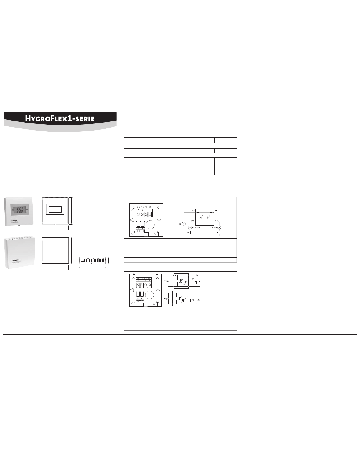
Terminal confi guration / Connection diagrams
The type is defi ned using the table «Supply voltage / Technology» to then use the following
connection diagrams:
2- or 2x2-wire / HF120
Terminal Schematics Description
1 V
+ Supply voltage +
2 T– OUT Analogue temperature output
3 V+ Supply voltage +
4 H– OUT Analogue humidity output
3 / 4-wire circuit / HF13x
Terminal Schematics Description
1 V+ Supply voltage +/Phase
2 GND GND / Neutral
3 OUT1 Analogue humidity output +
4 OUT2 Analogue temperature output +
Current output
Voltage output
Digital transmitter for humidity & temperature:
Space version
SHORT INSTRUCTION MANUAL
A
Electrical installation
Caution:
Wrong supply voltages and excessively high loading of the outputs can
damage the transmitter.
Supply voltage / Technology
Type Supply voltage V+ Load Output
2- or 2x2 wire
HF120 10...28 VDC: 10 V + (0.02 x load) Max 500 Ω 4...20 mA
3/4 wire
HF132 15...40 VDC / 12... 28 VAC Max 500 Ω 4...20 mA
HF133 15...40 VDC / 12... 28 VAC Max 500 Ω 0...1 V
HF134 15...40 VDC / 12... 28 VAC Max 500 Ω 0...5 V
HF135 15...40 VDC / 12... 28 VAC Max 500 Ω 0...10 V
Congratulations on your purchase of the HygroFlex1-Series transmitter.
Please read these short instructions carefully before installing the device.
General description
The HygroFlex1-Series devices are universal transmitters for transmission of humidity and
(or) temperature measurements. Additional information can be found on the internet at:
www.rotronic.com
Dimensions / connections
Page 2
ROTRONIC AG, CH-8303 Bassersdorf
Tel. +41 44 838 11 44, www.rotronic.com
ROTRONIC Messgeräte GmbH, D-76275 Ettlingen
Tel. +49 7243 383 250, www.rotronic.de
ROTRONIC SARL, 56, F - 77183 Croissy Beaubourg
Tél. +33 1 60 95 07 10, www.rotronic.fr
ROTRONIC Italia srl, I- 20157 Milano
Tel. +39 2 39 00 71 90, www.rotronic.it
ROTRONIC Instruments (UK) Ltd, West Sussex RH10 9EE
Phone +44 1293 571000, www.rotronic.co.uk
ROTRONIC Instrument Corp, NY 11788, USA
Phone +1 631 427-3898, www.rotronic-usa.com
ROTRONIC Instruments Pte Ltd, Singapore 159836
Phone +65 6376 2107 www.rotronic.sg
ROTRONIC Shanghai Rep. Offi ce, Shanghai 200233, China
Phone +86 40 08162018, www.rotronic.cn
V+
GND
GND
OUT1
OUT2
=
~
V+
GND
GND
OUT1
OUT2
86
86
86
86
24
86
86
86
A
Mechanische Installation
Achtung:
Um korrekte Messwerte zu erhalten, muss darauf geachtet werden, dass der
Messumformer mit der zu messenden Luft umströmt wird.
1. Entfernen Sie, durch lösen der Schraube die Montageplatte.
2. Befestigen Sie die Montageplatte mit 2 Schrauben an der vorgesehenen Stelle.
Typ L
Typ S
Stromausgang
Spannungsausgang
Digitaler Messumformer für Feuchte- und Temperatur:
Raumversion
KURZBEDIENUNGSANLEITUNG
Klemmenbelegung / Anschlussschemata
Anhand der Tabelle «Versorgungsspannung / Technologie» wird der Typ defi niert, um folgende
Anschluss-Schemas verwenden zu können:
2- oder 2x2 Leiter / HF120
Klemme Schema Beschreibung
1 V
+ Spannungsversorgung +
2 T– OUT Temperatur-/Analogausgang
3 V+ Spannungsversorgung +
4 H– OUT Feuchte-/Analogausgang
3 / 4 Leiter Schaltung / HF13x
Klemme Schema Beschreibung
1 V+ Spannungsversorgung +/Phase
2 GND GND / Neutral
3 OUT1 Feuchte-/Analogausgang +
4 OUT2 Temperatur-/Analogausgang +
A
Elektrische Installation
Achtung:
Falsche Versorgungsspannungen sowie zu grosse Belastungen der Ausgänge
können den Messumformer beschädigen.
Versorgungsspannung / Technologie
Typ Spannungsversorgung V+ Bürde Ausgang
2- oder 2x2-Leiter
HF120 10...28 VDC: 10 V + (0.02 x Bürde) Max 500 Ω 4...20 mA
3/4-Leiter
HF132 15...40 VDC / 12... 28 VAC Max 500 Ω 4...20 mA
HF133 15...40 VDC / 12... 28 VAC Max 500 Ω 0...1 V
HF134 15...40 VDC / 12... 28 VAC Max 500 Ω 0...5 V
HF135 15...40 VDC / 12... 28 VAC Max 500 Ω 0...10 V
Programmierung
Die Grundeinstellungen der Geräte werden im Werk, gemäss Ihrer Bestellung, vorgenommen.
Die Transmitter werden im Werk justiert, sodass eine Überprüfung oder Nachjustierung bei
der Installation nicht notwendig ist. Die Geräte können sofort nach der Installation in Betrieb
genommen werden. Mit Hilfe der SW21 oder HW4 Software und einem Standard mini USB
Kabel können folgende Einstellungen durchgeführt werden:
• Neuskalierung der Ausgänge
• 1-Punkt Justierung
• Allgemeine Einstellungen
Vorgehensweise
• Anschluss der Spannungsversorgung
• Verbindung des Messumformes mit dem PC via mini USB Kabel
• Programmierung des Messumformers mit SW21 oder HW4
• Entfernen der Spannungsversorgung (Der Messumformer muss für min. 2 Sekunden
von der Spannung getrennt sein)
Fehlerquellen
Messwerte können durch folgende Einfl üsse beeinträchtigt werden:
Temperaturfehler
Durch zu kurze Angleichzeit, kalte Aussenwand, Heizkörper, Sonneneinstrahlung usw.
Feuchtefehler
Durch Dampf, Wasserspritzer, Tropfwasser oder Kondensation am Sensor usw. Jedoch wird
die Reproduzierbarkeit und Langzeitstabilität dadurch nicht beeinträchtigt, auch wenn der
Fühler über längere Zeit einer hohen Feuchte oder Sättigung mit Wasserdampf (Kondensation) ausgesetzt wurde.
Verschmutzung
Durch Staub in der Luft. Die Wahl des Fühlerfi lters ist abhängig vom Verschmutzungsgrad
des Messortes und ist periodisch zu reinigen oder zu ersetzen.
Periodische Kalibrierung des Fühlers / Transmitters
Sowohl der Temperatursensor als auch die dazugehörende Elektronik sind sehr stabil und
müssen nach der Werkskalibrierung normalerweise nicht verändert oder kalibriert werden. Die
Langzeitstabilität der ROTRONIC Hygromer Feuchtefühler ist typischerweise besser als 1 %rF pro
Jahr. Für eine maximale Genauigkeit empfehlen wir eine Kalibrierung der Fühler ca. alle sechs bis
zwölf Monate. In Anwendungen wo der Sensor Schadstoffen ausgesetzt ist, kann eine häufi gere
Kalibrierung notwendig sein. Die Kalibrierung kann durch den Benutzer selber vor Ort oder im
Labor bzw. in der Werkstatt vorgenommen werden. Die Elektronik muss normalerweise nicht
kalibriert werden, und kann im Feld auch nicht repariert werden. Bei Problemen wenden Sie
sich an den Service der Firma ROTRONIC AG.
Technische Daten (operation)
Temperatur -20...50 °C
Feuchte 0...100 %rF, nicht kondensierend
Genauigkeit %rF (10…90 %rF) <3 % rF
Genauigkeit °C (0…50 °C) <0.3 °C
Skalierung der analogen Ausgangssignale
Feuchte 0…100 %rF
Temperatur Je nach Bestellcode
Ausgänge Strom- oder Spannungssignal
Service Schnittstelle
Herzlichen Glückwunsch zum Kauf Ihres neuen HygroFlex1-Serie Messumformers.
Bitte lesen Sie diese Kurzanleitung genau durch, bevor Sie das Gerät installieren.
Allgemeine Beschreibung
Die HygroFlex1-Serie Geräte sind universelle Messumformer für die Übertragung von Feuchteund (oder) Temperaturmesswerten. Weitere Informationen fi nden Sie unter: www.rotronic.com
Abmessungen / Anschlüsse
Page 3

ROTRONIC AG, CH-8303 Bassersdorf
Tel. +41 44 838 11 44, www.rotronic.com
ROTRONIC Messgeräte GmbH, D-76275 Ettlingen
Tel. +49 7243 383 250, www.rotronic.de
ROTRONIC SARL, 56, F - 77183 Croissy Beaubourg
Tél. +33 1 60 95 07 10, www.rotronic.fr
ROTRONIC Italia srl, I- 20157 Milano
Tel. +39 2 39 00 71 90, www.rotronic.it
ROTRONIC Instruments (UK) Ltd, West Sussex RH10 9EE
Phone +44 1293 571000, www.rotronic.co.uk
ROTRONIC Instrument Corp, NY 11788, USA
Phone +1 631 427-3898, www.rotronic-usa.com
ROTRONIC Instruments Pte Ltd, Singapore 159836
Phone +65 6376 2107 www.rotronic.sg
ROTRONIC Shanghai Rep. Offi ce, Shanghai 200233, China
Phone +86 40 08162018, www.rotronic.cn
V+
GND
GND
OUT1
OUT2
=
~
V+
GND
GND
OUT1
OUT2
86
86
86
86
24
86
86
86
Type S
Transmetteurs numériques pour l’humidité
et la température: Version d’intérieur
MODE D'EMPLOI ABRÉGÉ
A
Type L
Installation mécanique
Attention:
Pour obtenir des valeurs de mesure correctes, il est impératif que le transmetteur
baigne dans l’air de l’environnement à mesurer.
1. Retirer la platine de montage en enlevant les vis.
2. Fixer la platine de montage avec 2 vis à l’endroit désiré.
Affectation des bornes / schémas de raccordement
Le tableau de tension d’alimentation / technologie sert à défi nir le type d’appareil pour
pouvoir utiliser les schémas de raccordement suivants:
2 conducteurs ou 2x2 conducteurs / HF120
Borne Schéma Description
1 V
+ Alimentation en tension +
2 T– OUT Sortie analogique température
3 V+ Alimentation en tension +
4 H– OUT Sor tie analogique humidité
Branchement 3 / 4 conducteurs / HF13x
Borne Schéma Description
1 V+ Alimentation en tension +/Phase
2 GND GND / Neutre
3 OUT1 Sortie analogique humidité +
4 OUT2 Sortie analogique température +
Sortie de courant
Sortie de tension
Nous vous félicitons d’avoir choisi le nouveau transmetteur de la série HygroFlex1.
Veuillez lire attentivement ce manuel abrégé avant d’installer l’appareil.
Généralités
Les appareils de la série HygroFlex1 sont des transmetteurs de mesure universels pour la
transmission de valeurs de mesure d’humidité et (ou) de température. Vous trouverez plus
d’informations sur www.rotronic.com
Dimensions / raccordements
A
Installation électrique
Attention:
Des tensions d’alimentation erronées ainsi que des sollicitations trop fortes
des sorties peuvent endommager le transmetteur de mesure.
Tension d’alimentation / technologie
Type Alimentation en tension V+ Charge Sortie
2 conducteurs ou 2x2 conducteurs
HF120 10...28 VDC: 10 V + (0.02 x Charge) Max 500 Ω 4...20 mA
3/4 conducteurs
HF132 15...40 VDC / 12...28 VCA Max 500 Ω 4...20 mA
HF133 15...40 VDC / 12...28 VCA Max 500 Ω 0...1 V
HF134 15...40 VDC / 12...28 VCA Max 500 Ω 0...5 V
HF135 15...40 VDC / 12...28 VCA Max 500 Ω 0...10 V
Programmation
Les réglages de base des appareils sont effectués en usine conformément à votre commande. Les transmetteurs de mesure sont ajustés en usine. De ce fait, une vérifi cation ou
réajustement lors de l’installation n’est pas nécessaire. Les appareils peuvent être mis en
service immédiatement après l’installation. Les réglages suivants peuvent être réalisés à
l’aide des logiciels HSW21 ou HW4 et d’un câble standard mini USB:
• Nouvel échelonnage des sorties
• Ajustage sur 1 point
• Réglages généraux
Procédure
• Raccordement de l’alimentation
• Raccordement du transmetteur de mesure avec le PC par le câble mini USB
• Programmation du transmetteur de mesure avec SW21 ou HW4
• Retrait de la source d’alimentation (le transmetteur de mesure doit être déconnecté de la
source d’alimentation pendant au moins 2 secondes)
Sources d’erreur
Les valeurs mesurées peuvent être faussées par les infl uences suivantes:
Erreur de température
Dues à un temps d’égalisation trop court, à des murs extérieurs froids, radiateurs, rayon-
nements du soleil etc.
Erreur d’humidité
Dues à la vapeur, aux projections d’eau, à de l’eau d’égouttage ou à la condensation
sur l’élément sensible, etc. Cependant, la reproductibilité et la stabilité à long terme
ne sont pas affectées par ces facteurs, même si le capteur a été exposé relativement
longtemps à une forte humidité ou saturation de vapeur d’eau (condensation).
Contamination: due à la poussière dans l’air.
Le choix du fi ltre de capteur dépend du degré de contamination du site de mesure. Le fi ltre
de capteur doit être régulièrement nettoyé ou remplacé.
Étalonnage périodique du capteur / transmetteur de mesure
L’élément sensible de température ainsi que l’électronique correspondante sont très
stables et ne doivent normalement pas être modifi és ou ajustés après leur étalonnage en
usine. La stabilité à long terme des capteurs pour l’humidité Hygromer de ROTRONIC est
typiquement inférieure à 1 %HR par an. Pour une précision maximale, nous recommandons
un étalonnage du capteur tous les six à douze mois. Dans des environnements où l’élément
sensible est soumis à des polluants, un étalonnage plus fréquent peut s’avérer nécessaire.
L’utilisateur peut réaliser l’étalonnage lui-même sur site, dans un laboratoire ou un atelier.
L’électronique ne nécessite normalement pas d’étalonnage et ne peut pas être réparée sur
site. En cas de problème, adressez-vous au secteur de service de la société ROTRONIC SA.
Caractéristiques techniques (opération)
Température -20...50 °C
Humidité 0...100 %HR, sans condensation
Précision %HR (10…90 %HR) <3 % HR
Précision °C (0…50 °C) <0,3 °C
Mise à l’échelle des signaux analogiques de sortie
Humidité 0…100 %HR
Température Selon le code de commande
Sorties Signal de courant ou de tension
Interface de service
Page 4

ROTRONIC AG, CH-8303 Bassersdorf
Tel. +41 44 838 11 44, www.rotronic.com
ROTRONIC Messgeräte GmbH, D-76275 Ettlingen
Tel. +49 7243 383 250, www.rotronic.de
ROTRONIC SARL, 56, F - 77183 Croissy Beaubourg
Tél. +33 1 60 95 07 10, www.rotronic.fr
ROTRONIC Italia srl, I- 20157 Milano
Tel. +39 2 39 00 71 90, www.rotronic.it
ROTRONIC Instruments (UK) Ltd, West Sussex RH10 9EE
Phone +44 1293 571000, www.rotronic.co.uk
ROTRONIC Instrument Corp, NY 11788, USA
Phone +1 631 427-3898, www.rotronic-usa.com
ROTRONIC Instruments Pte Ltd, Singapore 159836
Phone +65 6376 2107 www.rotronic.sg
ROTRONIC Shanghai Rep. Offi ce, Shanghai 200233, China
Phone +86 40 08162018, www.rotronic.cn
V+
GND
GND
OUT1
OUT2
=
~
V+
GND
GND
OUT1
OUT2
86
86
86
86
24
86
86
86
A
Ci congratuliamo per il Vostro acquisto di un nuovo trasmettitore della serie HygroFlex1.
Prima di installare lo strumento, si prega di leggere la presente guida rapida.
Descrizione generale
Gli apparecchi della serie HygroFlex1 sono trasmettitori universali, per la trasmissione
di valori di umidità e (o) temperatura. Per ulteriori informazioni consultate il nostro sito:
www.rotronic.com
Dimensioni / connessioni
Typo L
Typo S
Installazione meccanica
Attenzione:
per ottenere valore corretti di misurazione, si deve installare la trasmettitori in
modo che il fl usso d’aria la circondi.
1. Asportare la piastra di montaggio allentando le viti.
2. Fissare la piastra di montaggio con 2 viti al punto previsto di installazione.
Occupazione dei morsetti / schemi di collegamento
In base alla tabella Tensione di alimentazione / tecnologia si defi nisce il tipo, per poter
quindi utilizzare i seguenti schemi di collegamento:
2 o 2x2 conduttori / HF120
Morsetto Schema Descrizione
1 V+ Tensione di alimentazione +
2 T– OUT Uscita analogica temperatura
3 V+ Tensione di alimentazione +
4 H– OUT Uscita analogica umidità
Circuito a 3/4 conduttori / HF13x
Morsetto Schema Descrizione
1 V+ Tensione di alimentazione +/Fase
2 GND GND / Neutro
3 OUT1 Uscita analogica umidità +
4 OUT2 Uscita analogica temperatura +
Trasduttori digitali per umidità e temperatura:
Versione statica
MANUALE D'ISTRUZIONI BREVE
Uscita di corrente
Uscita di tensione
A
Installazione elettrica
Attenzione:
Tensioni di alimentazione errate o carichi eccessivi sulle uscite possono dan-
neggiare il trasmettitore.
Tensione di alimentazione / tecnologia
Typo Alimentazione di tensione V+ Carico Uscita
2 o 2x2 conduttori
HF120 10...28 VDC: 10 V + (0.02 x Carico) Max 500 Ω 4...20 mA
Conduttore 3/4
HF132 15...40 VDC / 12...28 VAC Max 500 Ω 4...20 mA
HF133 15...40 VDC / 12...28 VAC Max 500 Ω 0...1 V
HF134 15...40 VDC / 12...28 VAC Max 500 Ω 0...5 V
HF135 15...40 VDC / 12...28 VAC Max 500 Ω 0...10 V
Programmazione
Le impostazioni base dello strumento sono effettuate di fabbrica, in accordo al Vostro ordine.
I trasmettitori sono regolati di fabbrica e pertanto in fase di installazione non è necessario
effettuare un controllo o una ricalibrazione. Pertanto dopo l’installazione è possibile mettere
immediatamente in funzione gli strumenti. Utilizzando il software HW4 o SW21 e un cavo
mini USB standard, è possibile eseguire le seguenti operazioni:
• Cambio del campo scala delle uscite analogiche
• Calibrazione su 1 punto
• Cambio delle impostazioni generali
Procedura
• Connettere lo strumento ad una fonte di alimentazione
• Connettere lo strumento al PC usando un cavo mini-USB
• Programmare lo strumento usando il software SW21 o HW4
• Disconnettere lo strumento dall’alimentazione, per almeno due secondi, per render
effettive le nuove impostazioni
Fonti di errore
I valori di misura sono infl uenzati dalle seguenti condizioni:
Errore di temperatura:
dovuto a tempi ridotti di adattamento, parete esterna fredda, termosifone, esposizione ai
raggi solari ecc.
Errore di umidità:
dovuto a vapore, spruzzi d’acqua, gocciolio o condensa sul sensore ecc. Non vengono
però infl uenzate la riproducibilità e la stabilità lungo termine, anche se la sonda è stata
sottoposta a lungo ad un livello eccessivo di umidità o a saturazione con vapore acqueo
(condensa).
Sporcizia:
dovuta a polvere presente nell’aria. La scelta del fi ltro della sonda dipende dal livello di imbrattamento della sede di misurazione e tale fi ltro va pulito o sostituito ad intervalli regolari.
Calibrazione periodica della sonda / del trasmettitore
Sia il sensore per la temperatura sia i relativi dispositivi elettronici sono estremamente stabili
e di solito non vanno più modifi cati o calibrati dopo la calibrazione effettuata di fabbrica.
La stabilità a lungo termine della sonda per l’umidità Hygromer ROTRONIC risulta di solito
migliore rispetto ad un valore dell’ 1 % di umidità relativa/anno. Per ottenere la massima
precisione possibile, consigliamo di effettuare una calibrazione della sonda ogni sei – do-
dici mesi. Per applicazioni che prevedono un’esposizione del sensore a sostanze nocive
potrebbe essere necessario effettuare più spesso la calibrazione. La calibrazione può essere
effettuata direttamente dall’operatore in sede di applicazione o in un laboratorio o offi cina.
Ai dispositivi elettronici normalmente non serve la calibrazione, e non sono riparabili in
campo. In caso di problemi occorre rivolgersi al servizio di assistenza della Ditta Rotronic AG.
Dati tecnici (operativi)
Temperatura -20...50 °C
Umidità 0...100 %UR, non condensante
Precisione %UR (10…90 %UR) <3 % UR
Precisione °C (0…50 °C) <0,3 °C
Confi gurazione dei segnali di uscita analogici
Umidità 0…100 %UR
Temperatura In base al codice d'ordine
Uscite Segnali di corrente o di tensione
Interfaccia di servizio
 Loading...