How it Works
Log In / Sign Up
Buy Points
How it Works
FAQ
Contact Us
Questions and Suggestions
Users
Rosemount
Loading...
#
755R
775 WM
7D
775
3
781
2
848T
6
890
928
3
8600
2
8700 Series
3
8705
4
8707
2
8712C
8712D
8712D Series
8712E
2
8712EM
2
8712ES
8712H
2
8712U
8712
3
8714D
2
8721
8732C
8732E
6
8732EM
8732 Series
8750W
5
8750WA
8782
2
8800D
5
8800D Series
951C
3
775 01
C
CT4215
F
FCL
Flow
I
Incus
2
M
Millennium Air
2
MS
2
N
NGA 2000 FID
O
OCX 8800
On-Site
Oxymitter 4000
Oxymitter 5000
R
R305
RM2510
RM5800
RM708
RMCT
RMCT58
S
Series 8700
SOLU COMP II
T
T1056
2
TankRadar Pro
2
TankRadar Rex
TankRadar Rex 3900 Series
W
Wireless Pressure Gauge
WPG
4
WPG58
Loading...
Loading...
Nothing found
RMCT58
User Manual
154 pgs
2.98 Mb
0
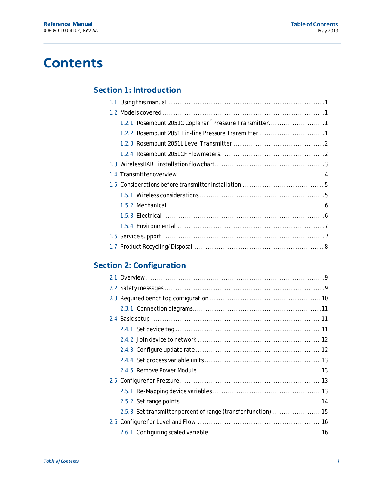
Table of contents
Loading...
Rosemount RMCT58 User Manual
...
Rosemount User Manual
Download
Specifications and Main Features
Frequently Asked Questions
User Manual
Download
Loading...
+
124
hidden pages
Unhide
You need points to download manuals.
1 point = 1 manual.
You can buy points or you can get point for every manual you upload.
Buy points
Upload your manuals
 Loading...