

Rosemount 396R, 396RVP Instruction Manual
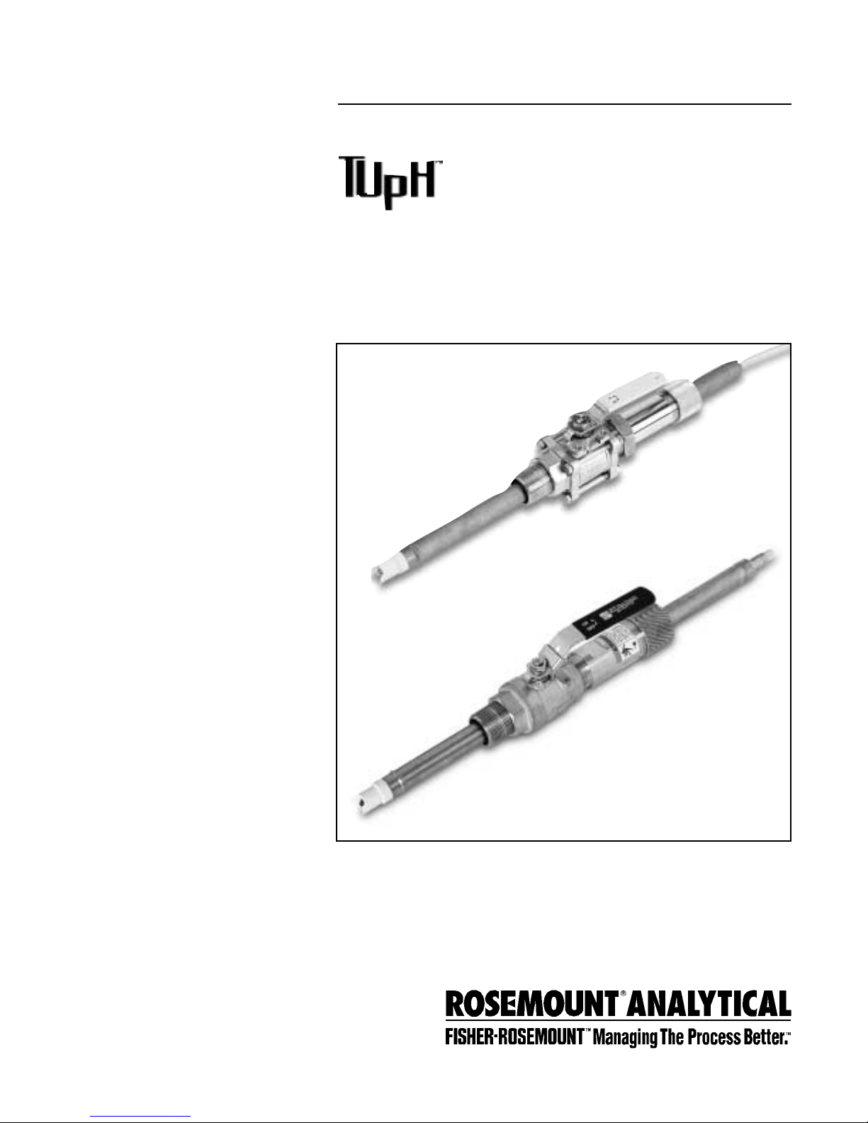
Model 396R and 396RVP
Retractable pH/ORP
Sensors
Instruction Manual
PN 5100396R
January 2001
WARNING
RETRACTABLE SENSORS
Retractable sensors must not be
inserted nor retracted when process
pressures are in excess of 64 psig
(542kPa), option 21 or 35 psig (343
kPa) option 25.
CAUTION
SENSOR/PROCESS
APPLICATION COMPATIBILITY
The wetted sensor materials may not
be compatible with process composition and operating conditions.
Application compatibility is entirely the
responsibility of the user.
DANGER
HAZARDOUS AREA INSTALLATION
Installations near flammable liquids or in hazardous area locations must be carefully evaluated by qualified on site safety personnel.
This sensor is not
Intrinsically Safe or
Explosion Proof.
To secure and maintain an intrinsically safe
installation, the certified safety barrier,
transmitter, and sensor combination must
be used. The installation system must comply with the governing approval agency
(FM, CSA or BASEEFA/CENELEC) hazardous area classification requirements.
Consult your analyzer/transmitter instruction
manual for details.
Proper installation, operation and servicing
of this sensor in a Hazardous Area Installation is entirely the responsibility of the user.
SS-SE
ESSENTIAL INSTRUCTIONS
READ THIS PAGE BEFORE PROCEEDING!
Rosemount Analytical designs, manufactures, and tests
its products to meet many national and international standards. Because these instruments are sophisticated technical products, you must properly install, use, and maintain them to ensure they continue to operate within their
normal specifications. The following instructions must be
adhered to and integrated into your safety program when
installing, using, and maintaining Rosemount Analytical
products. Failure to follow the proper instructions may
cause any one of the following situations to occur: Loss of
life; personal injury; property damage; damage to this
instrument; and warranty invalidation.
• Read all instructions prior to installing, operating, and
servicing the product. If this Instruction Manual is not
the correct manual, telephone 1-800-654-7768 and the
requested manual will be provided. Save this
Instruction Manual for future reference.
• If you do not understand any of the instructions, contact
your Rosemount representative for clarification.
• Follow all warnings, cautions, and instructions marked
on and supplied with the product.
• Inform and educate your personnel in the proper installation, operation, and maintenance of the product.
• Install your equipment as specified in the Installation
Instructions of the appropriate Instruction Manual and
per applicable local and national codes. Connect all
products to the proper electrical and pressure sources.
• To ensure proper performance, use qualified personnel
to install, operate, update, program, and maintain the
product.
• When replacement parts are required, ensure that qualified people use replacement parts specified by
Rosemount. Unauthorized parts and procedures can
affect the product’s performance and place the safe
operation of your process at risk. Look alike substitutions may result in fire, electrical hazards, or improper
operation.
• Ensure that all equipment doors are closed and protective covers are in place, except while maintenance is
being performed by qualified persons, to prevent electrical shock and personal injury.
Rosemount Analytical Inc.
Uniloc Division
2400 Barranca Parkway
Irvine, CA 92606 USA
Tel: (949) 863-1181
© Rosemount Analytical Inc. 2001

MODEL 396R pH/ORP TABLE OF CONTENTS
MODEL 396R AND 396RVP RETRACTABLE
pH/ORP SENSORS
TABLE OF CONTENTS
Section Title Page
1.0 DESCRIPTION AND SPECIFICATIONS............................................................. 1
1.1 Features and Applications................................................................................ 1
1.2 Performance and Physical Specifications ........................................................ 1
1.3 Ordering Information......................................................................................... 2
2.0 INSTALLATION.................................................................................................. 5
2.1 Unpacking and Inspection................................................................................ 5
2.2 Mechanical Installation .................................................................................... 5
3.0 WIRING MODEL 396R...................................................................................... 13
4.0 WIRING MODEL 396RVP.................................................................................. 22
5.0 START UP AND CALIBRATION......................................................................... 29
5.1 Start up.............................................................................................................. 29
5.2 pH Calibration................................................................................................... 29
5.3 ORP Calibration ................................................................................................ 30
6.0 MAINTENANCE................................................................................................. 31
6.1 Maintenance ..................................................................................................... 31
6.2 Sensor Removal................................................................................................ 31
6.3 pH Electrode Cleaning...................................................................................... 31
6.4 Platinum Electrode Cleaning............................................................................. 32
6.5 Automatic Temperature Compensation............................................................. 32
6.6 Sensor Tube Replacement................................................................................ 32
7.0 DIAGNOSTIC AND TROUBLESHOOTING ....................................................... 35
7.1 Diagnostics and Troubleshooting with Model 54/3081 pH/ORP Diagnostics... 35
7.2 Troubleshooting without Diagnostics................................................................ 36
8.0 RETURN OF MATERIAL.................................................................................... 37
LIST OF TABLES
Table No. Title Page
1-1
Commonly Used Accessories for Model 396R................................................. 3
1-2 Other Accessories for Model 396R................................................................... 3
1-3 Commonly Used Accessories for Model 396RVP............................................. 4
1-4 Other Accessories for Model 396RVP............................................................... 4
5-1 ORP of Saturated Quinhydrone Solutions......................................................... 30
6-1 Ro and R1 Values for Temperature Compensation Elements........................... 32
6-2 Temperature vs. Resistance of Auto T.C. Elements .......................................... 32
7-1 Troubleshooting with Diagnostics..................................................................... 35
7-2 Troubleshooting without Diagnostics................................................................ 36
i

MODEL 396R pH/ORP TABLE OF CONTENTS
LIST OF FIGURES
Figure No. Title Page
2-1 Exploded View of Ball Valve Kit PN 23240-00 used with process connector
PN 23166-00 (or PN 23166-01)......................................................................... 6
2-2 Typical Mounting Configurations for Model 396R............................................. 7
2-3 Typical Mounting Configurations for Model 396RVP......................................... 7
2-4 Dimensional Drawing — Model 396R with Optional Ball Valve PN 23765-00 .. 8
2-5 Dimensional Drawing — Model 396R with Optional Ball Valve PN 23240-00 .. 9
2-6 Dimensional Warning Label for Hemi Bulb Sensors and Sensor Diagram....... 10
2-7 Dimensional Drawing — Model 396RVP with Optional 1-1/2 inch Ball Valve ..
PN 23240-00..................................................................................................... 11
2-8 Dimensional Drawing — Model 396RVP with Optional 1-1/4 inch Ball Valve ......
PN 23765-00..................................................................................................... 12
3-1 Cable Preparation Instructions for Model 396R................................................ 13
3-2 Wiring Details Model 396R-54 for use with Model 54/81/3081 pH/ORP........... 14
3-3 Wiring Details Model 396R-54 with Remote Junction Box & Pr eamp (PN 23555-00) 14
3-4 Wiring Details Model 396R-50 for use with Remote Junction Box (PN 23309-03). 15
3-5 Wiring Details Model 396R-54 for use with Remote Junction Box (PN 23309-04). 15
3-6 Wiring Details-Model 396R-54 for use with Model 1181 pH/ORP......................... 16
3-7 Wiring Details-Model 396R-54 for use with Models 1054A/B pH/ORP, 2054 pH, ..
and 2081 pH/ORP.............................................................................................. 16
3-8 Wiring Details-Model 396R-54 for use with Model SCL- (P/Q).............................. 17
3-9 Wiring Details-Model 396R-54 for use with Model 2700 Pr eamp J-Box (PN 23054-03) 17
3-10 Wiring Details-Model 396R-50/54-60 for use with Sensor Head J-Box ............ 18
3-11 Wiring Details-Model 396R-54-61 for use with Sensor Head J-Box ................. 18
3-12 Wiring Details-Model 396R-50 for use with J-Box (PN 23707-00) to................
Models 1181, 1050, 1060, 1030, 1023 pH Transmitters .................................. 19
3-13 Wiring Details-Model 396R-54 for use with J-Box (PN 23708-01) to ...............
Models 1054series, 2054, and 2081 pH Transmitters ...................................... 20
3-14 Wiring Model 396R-( )-54-62-(71) to Model 1055-10-22-32 ............................. 21
3-15 Wiring Model 396R-(02)-( )-54/55-(61) to Model 1055-10-22-32...................... 21
4-1 Wire Functions and Pin Connections for Model 396RVP.................................. 22
4-2 Wiring Model 396RVP to Model 81 ................................................................... 23
4-3 Wiring Model 396RVP to Model 1181 ............................................................... 23
4-4 Wiring Model 396RVP to Model 81 thru a Remote J-Box.................................. 23
4-5 Wiring Model 396R VP to Models 1181/1050/1060/1003/1023 thru Remote J-Box 23
4-6 Wiring Model 396RVP to Model 2081 ............................................................... 24
4-7 Wiring Model 396RVP to Models 3081 and 4081 ............................................. 24
4-8 Wiring Model 396RVP to Model 2081 thru a Remote J-Box.............................. 24
4-9 Wiring Model 396RVP to Models 3081 and 4081 thru a Remote J-Box............ 24
4-10 Wiring Model 396RVP to Model 1054............................................................... 25
4-11 Wiring Model 396RVP to Models 1054A/B and 2054........................................ 25
4-12 Wiring Model 396RVP to Model 1054 thru a Remote J-Box.............................. 25
4-13 Wiring Model 396RVP to Models 1054A/B and 2054 thru a Remote J-Box...... 25
4-14 Wiring Model 396RVP to Model 54................................................................... 26
4-15 Wiring Model 396RVP to Model 54 thru a Remote J-Box.................................. 26
4-16
Wiring Model 396RVP to Model 2700............................................................... 26
4-17 Wiring Model 396RVP to Model SCL-(P/Q)....................................................... 26
4-18 Wiring Model 396RVP to Model 1055pH/pH..................................................... 27
4-19 Wiring Model 396RVP to Model 1055pH/pH thru a Remote J-Box................... 27
4-20
Wiring Model 396RVP to Model 1055-10-22-32................................................ 28
6-1 Sensor Tube Replacement................................................................................ 34
6-2 Male Connector Tightening Diagram................................................................ 34
ii

1.1 FEATURES AND APPLICATIONS
The Model 396R and 396RVP Sensorsare specifical-
ly designed for improv ed life in harsh, dirty applications
where a separate sample stream is difficult to provide
and greater insertion depths are required. Model 396R
is designed for use with a 1-1/4 in.or 1-1/2 in.ball valve
for hot tap installation.The Model 396R is constructed
of molded polypropylene housed in a titanium tube with
EPDM seals to provide maximum chemical resistance.
Model 396R also features a titanium solution ground
for advanced sensor diagnostics when used with the
Model 54, 81, or 3081 pH/ORP Analyzer/Transmitter.
Advanced sensor diagnostics provide preventative
maintenance by notifying the operator for replacement
and cleaning of an aged or fouled sensor for continuous optimum performance.
The sensor also features a shrouded tip for protection
from breakage while allowing process to flow by the glass
electrode for accurate and reliable pH measurement.
The Model 396R is available without an integral preamplifier only and 15 ft or 9.5 in. of integral high quality 9 conductor cable.The preamplifier must be housed
in a remote location or in a J-Box kit for attachment at
the rear, cable end of the sensor (order separately) or
integral to the Analyzer/Transmitter. The Model 396R
is compatible with all Rosemount Analytical and various other manufacturers instruments.
Model 396RVP: Rosemount Analytical has recently
released Model 396RVP.This model has identical performance and physical specifications to the Model
396R (see Section 1.2) with the following exception:
the Model 396RVP has a Variopol (VP) connector on
the back end of the sensor in place of a cable.
MODEL 396R pH/ORP SECTION 1.0
DESCRIPTION AND SPECIFICATIONS
SECTION 1.0
DESCRIPTION AND SPECIFICATIONS
MODEL 396R
Measured Range:
ORP: -1500 to 1500mV
pH:GPLR A
CCUGLASS
™
Percent Linearity Over pH Range:
Wetted Materials: Polypropylene, EPDM, titanium, glass,
(platinum: ORP only)
Process Connections: 1-1/2 or 1-1/4 in. with ball valve,
1 in. without ball valve
Cable: Integral 15 ft or 9.5 in. 9 conductor cable except
option 60 (9.5 in. coaxial cable with BNC)
Recommended Interconnect (PN 9200273)
Maximum Process Pressure and Temperature:
Hemi bulb: 150 psig (1136 kPa abs) at 212°F (100°C )
Flat bulb: 100 psig (790 kPa abs) at 212°F (100°C )
Maximum Pressure at Retraction or Insertion:
Code 21: 64 psig (542 kPa abs)
Code 25: 35 psig (343 kPa abs)
Minimum Conductivity: 100 µS/cm
Weight/Shipping Weight:
Sensor: Code 21: 2.0 lb/3.0 lb (.9 kg/1.40 kg)
Code 25: 3.0 lb/4.0 lb (1.40 kg/1.80 kg)
Ball Valve: PN 23240-00; 5 lb/7 lb (2.25 kg /3.20 kg)
PN 23634-00 8 lb/10 lb (3.65 kg/4.55 kg)
J-Box: 3 lb/4 lb (1.40 kg/1.80 kg)
MODEL 396RVP
Measured Range:
ORP: -1500 to 1500mV
pH:0 to 14
Available pH glass types:GPLR hemi bulb or flat bulb
Wetted Materials: Polypropylene, EPDM, titanium, glass,
(platinum: ORP only)
Process Connections: none, use 1-inch process connector
or ball valve kit (1-1/2 inch or 1-1/4 inch)
Temperature Range: 0 to 100C (32 to 212F)
Pressure Range (hemi bulb): 100-1136 kPa abs (0-150 psig)
Pressure Range (flat bulb): 100-790 kPa abs (0-100 psig)
Maximum Pressure at Retraction or Insertion:
Code 21: 64 psig (542 kPa abs)
Code 25: 35 psig (343 kPa abs)
Minimum Conductivity: 75 µS/cm, nominal
Preamplifier options: remote
Weight/Shipping Weight:
Sensor: Code 21: 2.0 lb/ 3.0 lb (.9 kg/1.40 kg)
Code 25: 3.0 lb/4.0 lb (1.40 kg/1.80 kg)
Ball Valve: PN 23240-00; 5 lb/7 lb (2.25 kg /3.20 kg)
Hemi Bulb Flat Bulb
1-2 pH 94% 93%
2-12 pH 99% 98%
12-13 pH 97% 95%
1
1.2 PERFORMANCE AND PHYSICAL SPECIFICATIONS
2
MODEL 396R pH/ORP SECTION 1.0
DESCRIPTION AND SPECIFICATIONS
1.3 ORDERING INFORMATION
The Model 396R Sensor is housed in a titanium tube, with a patented polypropylene reference junction and tita-
nium solution ground for use with a ball valve (order separately) for hot tap applications.The sensor is available
with either a hemi or flat glass pH electrode and features a shrouded glass/platinum electrode and PT100 or 3K
temperature compensation. The 396R is available with 9.5 in. or 15 ft of integral cable. The 396R sensor is not
available with a preamp. Junction box kits with preamps must be ordered separately if the analyzer/transmitter
does not have an integral preamp within 15 ft.of the probe. Process connector and ball valve assemblies m ust also
be ordered separately.
MODEL
396R TUpH RETRACTABLE pH SENSOR
CODE MEASURING ELECTRODE TYPE (Required Selection)
10 GPLR hemi glass, General Purpose Low Resistivity (0-14 pH)
12 ORP
13 GPLR flat glass, General Purpose Low Resistivity (0-14 pH)
CODE SENSOR LENGTH
21 21 in. Titanium Tube
25 36 in. Titanium Tube
CODE ANALYZER/TC COMPATIBILITY (Required Selection)
50 For Models 1181 (3K TC)
54 For Models 1054, 1054A/B, 2054, 2081,54, 3081, 81, SCL-(P/Q), Solu Cube (PT 100 RTD)
CODE OPTIONAL OPTIONS
60 9.5 in. Cable with BNC (for use with Model 1181, 1054 series, 2054, 2081 Sensor Head J-Boxes)
61 9.5 in. Cable no BNC (Not Valid w/Option 50) (for use with Model 54, 81, 3081 Sensor Head J-Boxes)
396R - 10 - 21 - 54 EXAMPLE
MODEL
396RVP TUpH RETRACTABLE pH/ORP SENSOR
CODE MEASURING ELECTRODE TYPE (Required Selection)
10 Hemi bulb, General Purpose Low Resistivity (0-14 pH)
12 ORP
13 Flat, GPLR glass
CODE SENSOR LENGTH (Required Selection)
21 21 in. Titanium Tube
25 36 in. Titanium Tube
CODE ANALYZER/TC COMPATIBILITY (Required Selection)
50 For Models 1181 (3K TC)
54 For Models 1054, 1054A, 1054B, 2054, 2081,54, 3081, 4081, 81, SCL-(P/Q), 2700 (Pt 100 RTD)
The Model 396RVP ball valve retractable sensor features a gel-filled electrolyte solution with the large area,
coating resistant TUpH polypropylene reference junction and a standard hemi or optional flat glass bulb. Model
396RVP is housed in a Titanium sensor tube and can be mounted directly into the process using a 1 in. MNPT
threaded process connector and a ball valve assembly kit (both ordered separately). It is offered with the watertight Variopol sensor-to-cable connector and uses the mating connector cable (ordered separately). Also available
is a choice of temperature element, 3 K Balco or Pt 100 RTD. A remote preamplifier found in the analyzer/transmitter or in a junction box (ordered separately) must be used with this sensor for a reliable signal transmission.
396RVP- 10 - 21 - 54 EXAMPLE

TABLE 1-2. OTHER ACCESSORIES FOR MODEL 396R
TABLE 1-1. COMMONLY USED ACCESSORIES FOR MODEL 396R
PART DESCRIPTION
22698-00 Preamplifier plug-in for J-box, for Model 1003,
22698-02 Preamplifier plug-in for J-box, for Models 1181/1050
22698-03 Preamplifier plug-in for J-box, for Models 1054A/B, 2054, 2081
23550-00 Remote Junction box with extension board
9550167 O-ring, 2-214, EPDM for process connector
9210012 Buffer solution, 4.01 pH, 16 oz
9210013 Buffer solution, 6.86 pH, 16 oz
9210014 Buffer solution, 9.18 pH, 16 oz
22743-01 Pt100 preamp for Model 1181
22744-01 3K Preamp for Model 1181
23557-00 Preamplifier for junction box for Models 54/3081
MODEL 396R pH/ORP SECTION 1.0
DESCRIPTION AND SPECIFICATIONS
3
For first time installations, Rosemount Analytical recommends using the following guide
1. Retractable Mounting
AA.. CChhoooossee oonnee ((rreeqquuiirreedd ffoorr aallll ffiirrsstt ttiimmee iinnssttaallllaattiioonnss))::
PN 23166-00, 1 in. x 1 in. NPT process connector, 316 SST
PN 23166-01, 1 in. x 1 in. NPT process connector, Titanium
BB.. CChhoooossee oonnee::
PN 23240-00, 1-1/2 in. ball valve assembly, 316 SST
PN 23765-00, 1-1/4 in. ball valve assembly, 316 SST
2. Junction Boxes (Optional; Choose either Sensor Head or Remote)
AA.. SSeennssoorr HHeeaadd JJuunnccttiioonn BBooxxeess ((uusseedd wwiitthh ooppttiioonnss -6600 oorr -6611 sseennssoorr)) - CChhoooossee oonnee::
PN 23709-00; includes preamplifier for Models 54, 81, 3081
PN 23708-01; includes preamplifier for Models 1054 series, 2054, 2081
PN 23707-00; includes preamplifier for Model 1181
BB.. RReemmoottee JJuunnccttiioonn BBooxxeess ((uusseedd wwiitthh ssttaannddaarrdd 1155 fftt.. ccaabbllee lleennggtthh sseennssoorr)) - CChhoooossee oonnee::
PN 23555-00; includes preamplifier for Models 54, 81, 3081
PN 23309-03; includes preamplifier for Model 1181
PN 23309-04; includes preamplifier for Models 1054 series, 2054, 2081
PN 23054-03; includes preamplifier for Solu Cube Model 2700
3. BNC Adapter - Choose one:
PN 9120516, BNC Adapter for use with remote junction boxes PN’s 23309-03 and 23309-04
Order option -60 (standard with BNC connector) for PN 23707-00 or 23708-01 sensor head junction boxes
4. Extension Cables - Choose one:
PN 23646-01, 11 conductor, shielded, prepped
PN 9200273, 11 conductor, shielded, unprepped

TABLE 1-4. OTHER ACCESSORIES FOR MODEL 396RVP
PART DESCRIPTION
22698-00 Preamplifier plug-in for junction box, for Model 1003,
22698-02 Preamplifier plug-in for junction box, for Models 1181, 1050
22698-03 Preamplifier plug-in for junction box, for Models 1054A/B, 2054, 2081
22743-01 Pt100 preamplifier for Model 1181
22744-01 3K Preamplifier for Model 1181
23557-00 Preamplifier for junction box for Models 54, 3081, 81, 4081
33046-00 Ferrule, 1 in., split 316SS
9310096 Nut, swage, 1 in. 316SST
9210012 Buffer solution, 4.01 pH, 16 oz
9210013 Buffer solution, 6.86 pH, 16 oz
9210014 Buffer solution, 9.18 pH, 16oz
R508-160Z ORP solution, 460 mv ± 10 at 20°C
9550167 EPDM O-ring for Process Connector (PN 23166-00 or 23166-01)
12707-00 Jet Spray Cleaner
1. Variopol Cable (required for all first time installations)
Choose one: PN 23645-06, 15 ft cable with mating VP connector, prepped with BNC on analyzer end
PN 23645-07, 15 ft cable with mating VP connector, prepped without BNC on analyzer end*
2. Retractable Mounting
1A. Choose one (required for all first time installations, except as noted):
PN 23166-00 1 in. x 1 in. NPT process connector, 316 SST
PN 23166-01 1 in. x 1 in. NPT process connector, Titanium
Choose one (optional process connector o-rings):
PN 9550220, Kalrez o-ring, 2-214
PN 9550099, Viton o-ring, 2-214
1B. Choose one:
PN 23240-00 1-1/2 in. ball valve assembly, 316 SST
PN 23765-00 1-1/4 in. ball valve assembly, 316 SST (process connector not needed)
3. Remote Junction Boxes (Optional)
Choose one: PN 23555-00 includes preamplifier for Models 54, 81, 3081, 4081
PN 23309-03 and PN 22698-02 plug-in preamplifier for Model 1181Analyzer
PN 23309-04 and PN 22698-03 plug-in preamplifier for Models 1054 series, 2054, 2081 Analyzers
PN 23054-03 includes preamplifier for Solu Cube Model 2700
4. Extension cables
Choose one: PN 23646-01, 11 conductor, shielded, prepped
PN 9200273, 11 conductor, shielded, unprepped
FOR FIRST TIME 396RVP AND 398RVP INSTALLATIONS, ROSEMOUNT ANALYTICAL RECOMMENDS USING THE FOLLOWING GUIDE:
* Used for connections to Models 1181, 1054, 2081, 54, 81, 3081, 4081, and remote junction box PN 23555-00.
MODEL 396R pH/ORP SECTION 1.0
DESCRIPTION AND SPECIFICATIONS
4
TABLE 1-3. COMMONLY USED ACCESSORIES FOR MODEL 396RVP

5
MODEL 396R pH/ORP SECTION 2.0
INSTALLATION
SECTION 2.0
INSTALLATION
2.1 UNPACKING AND INSPECTION. Inspect the out-
side of the carton for any damage. If damage is
detected, contact the carrier immediately. Inspect the
instrument and hardware. Make sure all items in the
packing list are present and in good condition. Notify
the factory if any part is missing.
NOTE
If the sensor is to be stored, the protective
boot should be filled with either KCl electrolyte solution or pH 4.0 buffer solution
and replaced on sensor tip until ready to
use.
NOTE
Save the original packing cartons and
materials as most carriers require proof of
damage due to mishandling, etc. Also, if it
is necessary to return the instrument to the
factory, you must pack the instrument in
the same manner as it was received. Refer
to Section 6.0 for instructions.
WARNING
Glass electrode must be wetted at all
times (in storage and in line) to maximize
sensor life.
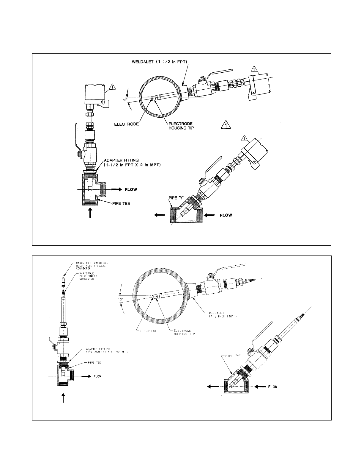
2.2 MECHANICAL INSTALLATION. The Model 396R
Sensor may be installed through a weldalet or in a
pipe tee or “Y”, as shown in Figure 2-1, when used
with a ball valve. Insert the end of the sensor to a
depth sufficient to ensure that the glass bulb is continuously wetted by the process fluid. The Model 396R
can also be inserted directly into the process without
the use of a ball valve for applications not requiring
continuous operation during sensor maintenance.
CAUTION
Allow sufficient room for safe retraction
and insertion of the sensor. Personnel
should have room for stable footing while
performing removal or insertion of the sensor.
The sensor must be mounted within 10-90 degrees of
the horizontal with the tip pointed downward, thus
keeping air bubbles off of the pH sensitive glass bulb.
Bubbles settled on the glass bulb disrupt the electrical continuity between the pH sensitive glass and the
silver/silver chloride measuring element.
If the retraction version is to be installed without a ball
valve follow the installation procedure for insertion
service (Section 2.2.2). Perform the following steps for
sensor installation through a ball valve:
2.2.1 INSTALLATION THROUGH BALL VALVE.
1. Carefully remove the liquid filled rubber boot
which protects the glass electrode and keeps the
liquid junction wet during shipping and storage.
Discard the liquid and boot. Make sure the lubricated O-ring is in place in the groove inside the
male connector on the sensor body (Figure 4-1,
item A).
CAUTION
Buffer solution, in the protective boot, may
cause skin or eye irritation.
2. With the male connector on the sensor’s body,
insert the sensor into the ball valve until it gently
touches the closed valve. The molded electrode
guard will protect the glass bulb from breakage.
3. Thread the male connector body tightly into the
ball valve assembly. DO NOT tighten the hex nut
on the male connector body; doing so would not
allow the sensor to be inserted through the ball
valve.
4. Pull back hard on the sensor assembly, as if trying to remove the sensor, to be certain that the
sensor cannot come free of the ball valve assembly . The built-in r etraction stop will butt against the
shoulder of the male connector if properly
installed.
CAUTION
The sensor must be captured by the valve
assembly and the male connector so that
it cannot be blown free by process pressure if mishandled during insertion or
retraction.
5. After confirming that the sensor assembly is properly secured by the valve assembly, the valve may
be opened and the sensor positioned into the
process at the desired depth and orientation.
6. While holding the sensor in position, tighten the hex
nut of the male connector to firmly secure the sensor in place. When the hex nut is tightened, the
Teflon ferrule inside the compression fitting clamps
the sensor tube (see Figure 4-2).
NOTE
A stainless steel ferrule is available if the
Teflon ferrule does not inadequately grip.
When using the metallic ferrule, care must be
taken to avoid over tightening and damaging
the sensor tube. If the male connector leaks
during insertion or retraction, replace the Oring in the male connector.
2.2.2 INSTALLATION WITHOUT A BALL VALVE. The
Model 396R Sensor may be installed through a weldalet
or pipe tee or “Y” when used with a process connector
(PN 23166-00 or 23166-01). The sensor should be
installed within 80° of vertical, with the electrode facing
down.
MODEL 396R pH/ORP SECTION 2.0
INSTALLATION
CAUTION
Over tightening the hex nut may
damage the ferrule.
6
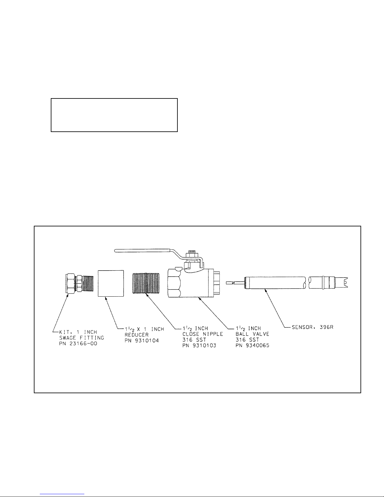
FIGURE 2-1. Exploded View of Ball Valve Kit PN 23240-00
used with process connector PN 23166-00 (or PN 23166-01)
7
MODEL 396R pH/ORP SECTION 2.0
INSTALLATION
JUNCTION BOX IS OPTIONAL
FIGURE 2-2.Typical Mounting Configurations for Model 396R
FIGURE 2-3.Typical Mounting Configurations for Model 396RVP
8
MODEL 396R pH/ORP SECTION 2.0
INSTALLATION
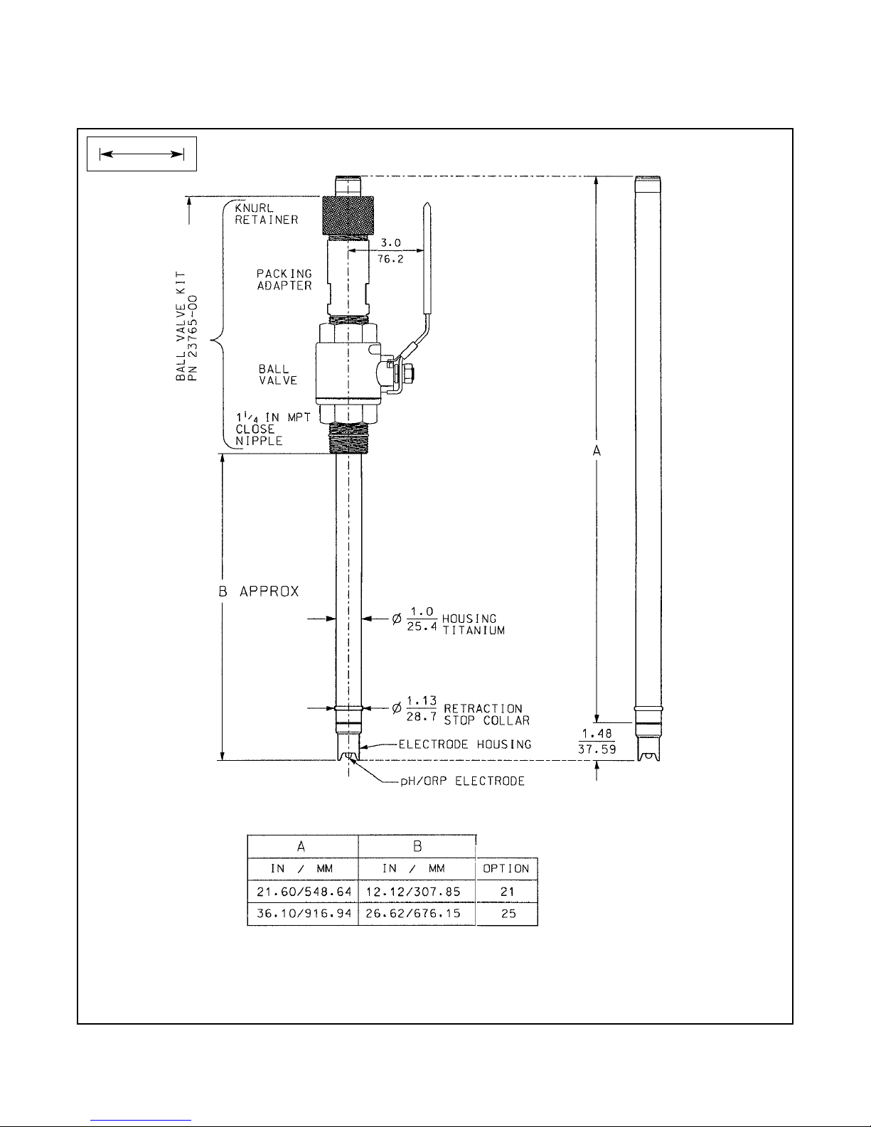
FIGURE 2-4. Dimensional Drawing — Model 396R with Optional Ball Valve PN 23765-00
Note: Add five (5) inches to dimension A if mounting a sensor head junction box onto the sensor.
INCH
MILLIMETER
9
MODEL 396R pH/ORP SECTION 2.0
INSTALLATION
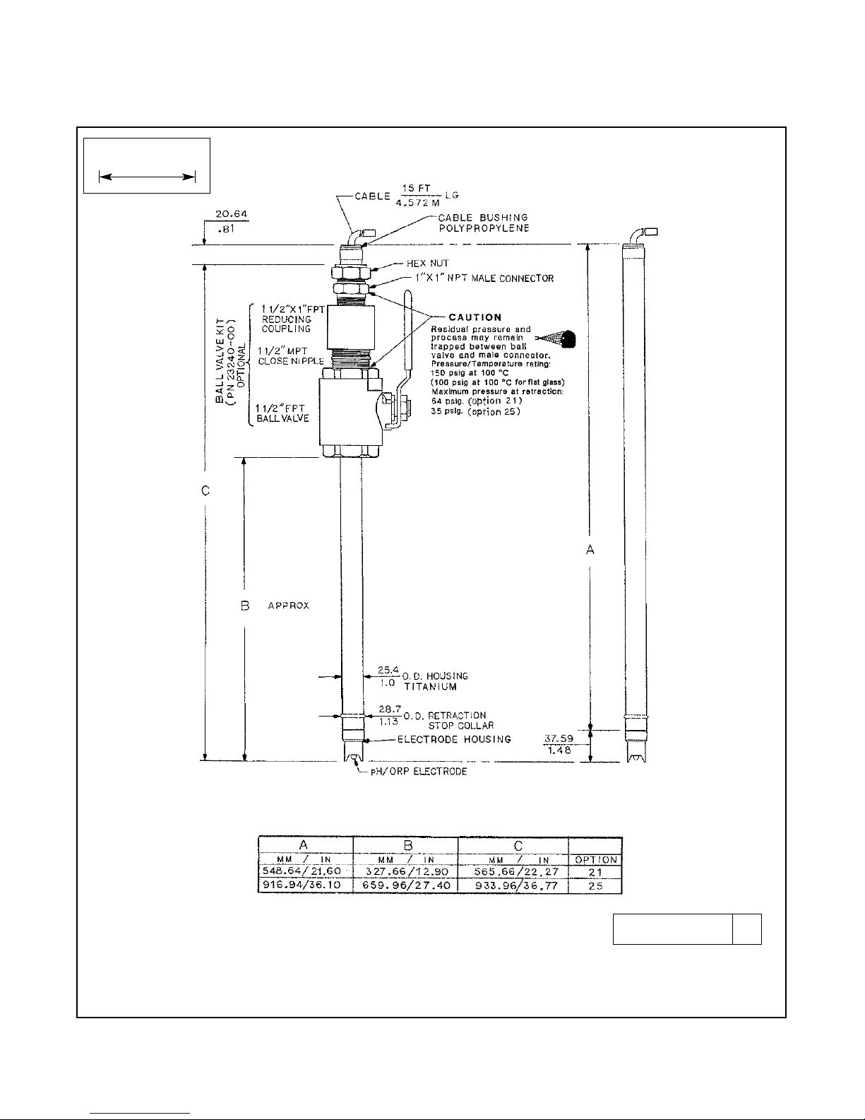
FIGURE 2-5. Dimensional Drawing — Model 396R with Optional Ball Valve PN 23240-00
Note: Add five (5) inches to dimension A if mounting a sensor head junction box onto the sensor.
DWG. NO. REV.
40396R05 A
WHEN INCH AND METRIC DIMS
ARE GIVEN
MILLIMETER
INCH
10
MODEL 396R pH/ORP SECTION 2.0
INSTALLATION
36”
36”
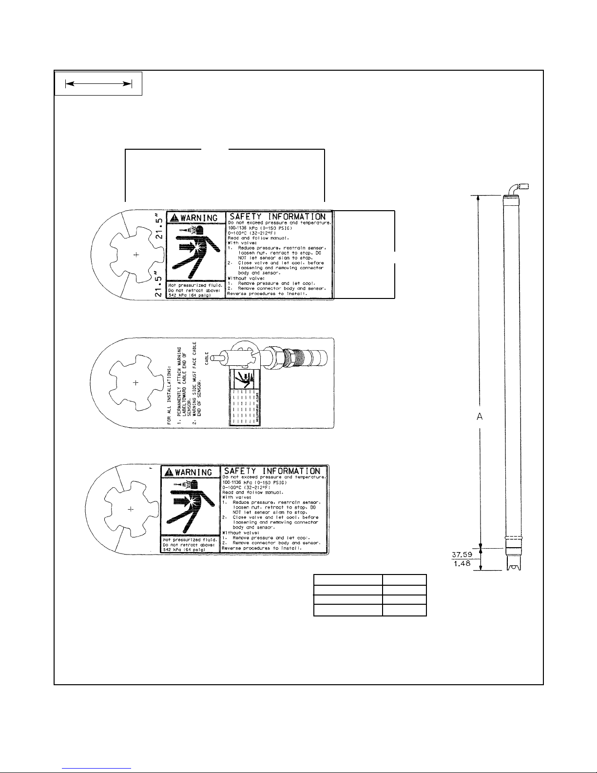
FIGURE 2-6. Dimensional Warning Label for Model 396R Hemi Bulb Sensors and Sensor Diagram
Note: Pressure rating for flat glass sensors is 100-790 kPa (0-100 psig).
Front Side 396R-21
Note: Retraction Pressure
4.920
2.25
Back Side 396R
Front Side 396R-25
Note: Retraction Pressure
A
MM / IN
548.64 / 21.60
916.94 / 36.10
OPTION
21
25
MILLIMETER
INCH
 Loading...