


Rosemount™ 2460 System Hub
for tank gauging systems
Reference Manual
00809-0100-2460, Rev EB
September 2021

Rosemount™ 2460 System Hub
NOTICE
Read this manual before working with the product. For personal and system safety, and for optimum product performance,
ensure you thoroughly understand the contents before installing, using, or maintaining this product.
For equipment service or support needs, contact your local Emerson Automation Solutions/Rosemount Tank Gauging
representative.
Spare Parts
Any substitution of non-recognized spare parts may jeopardize safety. Repair, e.g. substitution of components etc, may also
jeopardize safety and is under no circumstances allowed.
Rosemount Tank Radar AB will not take any responsibility for faults, accidents, etc caused by non-recognized spare parts or any
repair which is not made by Rosemount Tank Radar AB.
CAUTION
The products described in this document are NOT designed for nuclear-qualified applications. Using non-nuclear qualified
products in applications that require nuclear-qualified hardware or products may cause inaccurate readings. For information on
Rosemount nuclear-qualified products, contact your local Emerson Sales Representative.
2

Reference Manual Contents
00809-0100-2460 September 2021
Contents
Chapter 1 Introduction.............................................................................................................. 7
1.1 Safety messages.......................................................................................................................... 7
1.2 Symbols.......................................................................................................................................8
1.3 Manual overview..........................................................................................................................8
1.4 Technical documentation.......................................................................................................... 10
1.5 Service support..........................................................................................................................13
1.6 Product recycling/disposal.........................................................................................................13
1.7 Packing material........................................................................................................................ 13
Chapter 2 Overview................................................................................................................. 15
2.1 Introduction.............................................................................................................................. 15
2.2 Communication.........................................................................................................................16
2.3 Components..............................................................................................................................18
2.4 System overview........................................................................................................................22
2.5 Installation procedure................................................................................................................29
Chapter 3 Installation...............................................................................................................31
3.1 Section overview....................................................................................................................... 31
3.2 Safety messages........................................................................................................................ 31
3.3 Installation considerations.........................................................................................................32
3.4 Mechanical installation.............................................................................................................. 34
3.5 Electrical installation..................................................................................................................37
Chapter 4 Configuration...........................................................................................................59
4.1 Overview................................................................................................................................... 59
4.2 Safety messages........................................................................................................................ 59
4.3 Setting up a Rosemount 2460 System Hub................................................................................59
4.4 Inventory calculation configuration......................................................................................... 100
4.5 Strapping table configuration..................................................................................................107
Chapter 5 Operation.............................................................................................................. 109
5.1 Overview................................................................................................................................. 109
5.2 Safety messages...................................................................................................................... 109
5.3 Light emitting diodes...............................................................................................................109
5.4 Redundancy operation............................................................................................................ 114
Chapter 6 Service and troubleshooting.................................................................................. 121
6.1 Safety messages...................................................................................................................... 121
6.2 Tools........................................................................................................................................121
6.3 Troubleshooting......................................................................................................................122
6.4 Exchanging a modem card.......................................................................................................125
Rosemount 2460 System Hub 3

Contents Reference Manual
September 2021 00809-0100-2460
6.5 Exchanging the terminal board................................................................................................127
6.6 Replacing the power supply unit..............................................................................................129
6.7 Using the web interface........................................................................................................... 131
6.8 User settings............................................................................................................................136
6.9 View tank.................................................................................................................................137
6.10 Ports statistics....................................................................................................................... 140
6.11 Setup a communication log...................................................................................................141
6.12 Modbus TCP configuration.................................................................................................... 146
6.13 User defined Modbus.............................................................................................................147
6.14 Modbus TCP statistics............................................................................................................148
6.15 Time...................................................................................................................................... 149
6.16 Ports......................................................................................................................................150
6.17 Network................................................................................................................................ 154
6.18 Diagnostics............................................................................................................................164
6.19 Restore to factory defaults.....................................................................................................167
6.20 Create a backup of the current configuration.........................................................................169
6.21 Configuration recovery..........................................................................................................171
6.22 Firmware upgrade................................................................................................................. 173
6.23 License upgrade.....................................................................................................................177
6.24 Redundancy...........................................................................................................................180
6.25 Fuses..................................................................................................................................... 183
6.26 Write protection....................................................................................................................184
6.27 Replacing the backup battery................................................................................................ 186
6.28 Setting the real-time clock.....................................................................................................187
6.29 Maintenance..........................................................................................................................188
6.30 Modem cards.........................................................................................................................189
6.31 Simulation............................................................................................................................. 196
Appendix A Specifications and reference data........................................................................... 199
A.1 Communication/configuration specifications..........................................................................199
A.2 Electrical specifications............................................................................................................205
A.3 Mechanical specifications........................................................................................................205
A.4 Environmental specifications...................................................................................................206
A.5 Additional specifications..........................................................................................................206
A.6 Dimensional drawings............................................................................................................. 207
A.7 Ordering information.............................................................................................................. 209
Appendix B Product certifications............................................................................................. 215
B.1 European directive information............................................................................................... 215
B.2 Ordinary location certification................................................................................................. 215
B.3 Electromagnetic compatibility compliance..............................................................................215
B.4 Custody transfer certifications.................................................................................................215
4 Reference Manual

Reference Manual Contents
00809-0100-2460 September 2021
Appendix C Enraf® device configuration................................................................................... 217
C.1 Tank Database configuration for Enraf devices........................................................................ 217
C.2 Advanced Enraf configuration..................................................................................................219
Appendix D Servo commands....................................................................................................221
D.1 Send a servo command........................................................................................................... 221
D.2 Servo states.............................................................................................................................225
D.3 Type of request (TOR)............................................................................................................. 226
Appendix E Whessoe device configuration............................................................................... 227
E.1 Tank Database configuration for Whessoe devices...................................................................227
E.2 Advanced Whessoe configuration............................................................................................230
Appendix F Modbus® standard question.................................................................................. 235
F.1 Introduction.............................................................................................................................235
F.2 FC02 status register area..........................................................................................................236
F.3 FC03 register area....................................................................................................................238
F.4 FC04 register area....................................................................................................................240
F.5 User defined Modbus server mapping......................................................................................258
F.6 User defined Modbus device mapping..................................................................................... 261
Appendix G Fast polling............................................................................................................ 263
G.1 Overview.................................................................................................................................263
G.2 Configure fast polling with common threshold........................................................................263
G.3 Configure fast polling with individual thresholds..................................................................... 265
Appendix H L&J device configuration.........................................................................................269
H.1 Tank Database configuration for L&J devices........................................................................... 269
H.2 Advanced L&J configuration.................................................................................................... 271
Appendix I Varec® device configuration...................................................................................273
I.1 Tank Database configuration for Varec® devices....................................................................... 273
I.2 Advanced Varec configuration..................................................................................................275
Appendix J Enraf® 858 CIU configuration................................................................................. 277
J.1 Introduction............................................................................................................................. 277
J.2 Getting started......................................................................................................................... 278
J.3 Host port configuration............................................................................................................ 278
Appendix K TIC configuration................................................................................................... 281
K.1 Tank Database configuration for TIC devices........................................................................... 281
K.2 Advanced TIC device configuration..........................................................................................282
Appendix L Sakura configuration..............................................................................................283
L.1 Tank Database configuration for Sakura devices...................................................................... 283
L.2 Advanced Sakura device configuration.....................................................................................286
Appendix M NRF590 configuration............................................................................................ 289
M.1 Tank Database configuration for NRF590/4590 devices..........................................................289
Rosemount 2460 System Hub 5

Contents Reference Manual
September 2021 00809-0100-2460
6 Reference Manual

Reference Manual Introduction
00809-0100-2460 September 2021
1 Introduction
1.1 Safety messages
Instructions and procedures in this section may require special precautions to ensure the
safety of the personnel performing the operations. Information that potentially raises
safety issues is indicated by a warning symbol ( ). Refer to the following safety messages
before performing an operation preceded by this symbol.
WARNING
Failure to follow these installation guidelines could result in death or serious injury.
• Ensure only qualified personnel perform the installation.
• Use the equipment only as specified in this manual. Failure to do so may impair the
protection provided by the equipment.
• Ensure that the lid on the housing is closed during operation.
Electrical shock could cause death or serious injury.
• Use extreme caution when making contact with the leads and terminals.
WARNING
Any substitution of non-recognized parts may jeopardize safety. Repair (e.g. substitution
of components) may also jeopardize safety and is not allowed under any circumstances.
WARNING
Physical access
Unauthorized personnel may potentially cause significant damage to and/or
misconfiguration of end users’ equipment. This could be intentional or unintentional and
needs to be protected against.
Physical security is an important part of any security program and fundamental to
protecting your system. Restrict physical access by unauthorized personnel to protect end
users’ assets. This is true for all systems used within the facility.
Rosemount 2460 System Hub 7

Introduction
September 2021 00809-0100-2460
Reference Manual
1.2 Symbols
Table 1-1: Symbols
The CE marking symbolizes the conformity of the product with the applicable
European Community Directives.
Protective Earth
Ground
Caution - see reference manual
1.3 Manual overview
This manual provides information on installing, operating, and maintaining the
Rosemount™ 2460. The sections are organized as follows:
Chapter Overview provides a brief description of the various components in a Rosemount
Tank Gauging system and recommended installation procedure.
Chapter Installation covers installation considerations as well as mechanical and electrical
installation.
Chapter Configuration describes how to configure the Rosemount 2460 System Hub by
using the TankMaster WinSetup configuration program. This section includes inventory
calculations and how to setup a pair of redundant system hubs.
Chapter Operation describes what information that is provided by the LEDs.
Chapter Service and troubleshooting covers tools, troubleshooting, and various service
instructions.
Appendix Specifications and reference data contains specifications, dimensional drawings,
and ordering table.
Appendix Product certifications contains information on approvals and certifications.
Appendix Enraf® device configuration describes how to configure the Rosemount 2460
tank database using the TankMaster WinSetup configuration program. It also covers how
to configure fast polling and how to enable Vapor Temperature.
Appendix Servo commands describes various commands that can be used for tanks
configured as servo tanks.
Appendix Whessoe device configuration describes how to configure the tank database of
the Rosemount 2460 for Whessoe devices.
Appendix Modbus® standard question lists the database registers which can be scanned in
queries from a Modbus master.
8 Reference Manual

Reference Manual Introduction
00809-0100-2460 September 2021
Appendix Fast polling describes how to enable and configure fast polling for varioius
devices.
Appendix L&J device configuration describes how to configure the tank database of the
Rosemount 2460 for L&J devices.
Appendix Varec® device configuration describes how to configure the tank database of the
Rosemount 2460 for Varec devices.
Appendix Enraf® 858 CIU configuration describes how to configure the Rosemount 2460
for Enraf 858 CIU emulation.
Appendix TIC configuration describes how to configure the tank database of the
Rosemount 2460 for TIC devices.
Appendix Sakura configuration describes how to configure the tank database of the
Rosemount 2460 for Sakura devices.
Appendix NRF590 configuration describes how to configure the tank database of the
Rosemount 2460 for NRF590 devices.
Rosemount 2460 System Hub 9

Introduction Reference Manual
September 2021 00809-0100-2460
1.4 Technical documentation
The Rosemount™ Tank Gauging System includes a wide portfolio of user documentation.
For a complete list, see product pages on Emerson.com/Rosemount.
Reference manuals
• Rosemount Tank Gauging System Configuration Manual (00809-0300-5100)
• Rosemount 2460 System Hub (00809-0100-2460)
• Rosemount 2410 Tank Hub (00809-0100-2410)
• Rosemount 5900S Radar Level Gauge (00809-0100-5900)
• Rosemount 5900 Proof Test with Reference Reflector (00809-0200-5900)
• Rosemount 5900C Radar Level Gauge (00809-0100-5901)
• Rosemount 2240S Multi-Input Temperature Transmitter (00809-0100-2240)
• Rosemount 2230 Graphical Field Display (00809-0100-2230)
• Rosemount 5300 Guided Wave Radar (00809-0100-4530)
• Rosemount 5408 Radar Level Transmitter (00809-0300-4408)
• Rosemount Tank Gauging Wireless System (00809-0100-5200)
• Rosemount TankMaster WinOpi (00809-0200-5110)
• Rosemount TankMaster Software Installation Manual (00809-0400-5110)
• Rosemount TankMaster WinSetup (00809-0100-5110)
• Rosemount TankMaster Floating Roof Monitoring (00809-0500-5100)
• Rosemount TankMaster Network Configuration (303042EN)
• Rosemount 5900 Radar Level Gauge and Rosemount 2410 Tank Hub Safety Manual
Option S (00809-0400-5100)
• Rosemount TankMaster Mobile User Guide (00809-0100-5120)
• Rosemount TankMaster Mobile Installation Manual (00809-0200-5120)
10 Reference Manual

Reference Manual Introduction
00809-0100-2460 September 2021
Product data sheets
• Rosemount Tank Gauging System (00813-0100-5100)
• Rosemount TankMaster Inventory Management Software (00813-0100-5110)
• Rosemount TankMaster Mobile Inventory Management Software (00813-0100-5120)
• Rosemount 2460 System Hub (00813-0100-2460)
• Rosemount 2410 Tank Hub (00813-0100-2410)
• Rosemount 5900S Radar Level Gauge (00813-0100-5900)
• Rosemount 5900C Radar Level Gauge (00813-0100-5901)
• Rosemount 2240S Multi-input Temperature Transmitter (00813-0100-2240)
• Rosemount 565/566/765/614 Temperature and Water Level Sensors
(00813-0100-5565)
• Rosemount 2230 Graphical Field Display (00813-0100-2230)
• Rosemount 5300 Level Transmitter (00813-0100-4530)
• Rosemount 5408 Level Transmitter (00813-0100-4408)
Drawings
Table 1-2: Installation Drawings for the Rosemount 2460 System Hub
Drawing Title
D7000001-927 Mechanical Installation Drawing Rosemount 2460 System Hub
D7000001-928 Electrical Installation Drawing Rosemount 2460 System Hub
D7000003-069 Electrical Installation Drawing redundant Rosemount 2460 system
connection
D7000003-852 Electrical Installation Drawing Emulation
See web site on Emerson.com/Rosemount for latest issues.
Rosemount 2460 System Hub 11

Rosemount 2240S Reference Manual
(Document No. 00809-0100-2240)
Rosemount 2230 Reference Manual
(Document No. 00809-0100-2230)
Rosemount Tank Gauging System Configuration Manual
(Document No. 00809-0300-5100)
Rosemount TankMaster WinSetup Reference Manual
(Document No. 00809-0100-5110)
Rosemount TankMaster WinOpi Reference Manual
(Document No. 00809-0200-5110)
Rosemount TankMaster Software Installation Manual
(Document No. 00809-0400-5110)
Rosemount 2460 Reference Manual
(Document No. 00809-0100-2460)
Rosemount 2410 Reference Manual
(Document No. 00809-0100-2410)
Rosemount 5900S Reference Manual
(Document No. 00809-0100-5900)
Rosemount 5900C Reference Manual
(Document No. 00809-0100-5901)
Introduction Reference Manual
September 2021 00809-0100-2460
Figure 1-1: System and User Documentation Structure
12 Reference Manual

Reference Manual Introduction
00809-0100-2460 September 2021
1.5 Service support
For service support contact the nearest Emerson Automation Solutions /Rosemount Tank
Gauging representative. Contact information can be found on the web site
www.Emerson.com.
1.6 Product recycling/disposal
Recycling of equipment and packaging should be taken into consideration and disposed of
in accordance with local and national legislation/regulations.
1.7 Packing material
Rosemount Tank Radar AB is fully certified according to ISO 14001 environmental
standards. By recycling the corrugated paperboard, or wooden boxes, used for shipping
our products you can contribute to take care of the environment.
Reuse and recycling
Experience has shown that wooden boxes can be used several times for various purposes.
After careful disassembly the wooden parts may be reused. Metal waste may be
converted.
Energy recovery
Products which have served their time may be divided into wood and metal components
and the wood can be used as fuel in sufficient ovens.
Due to its low moisture content (approximately 7%) this fuel has a higher calorific value
than ordinary wood fuel (moisture content approximately 20%).
When burning interior plywood the nitrogen in the adhesives may increase emissions of
nitrogen oxides to the air 3-4 times more than when burning bark and splinter.
Note
Landfill is not a recycling option and should be avoided.
Rosemount 2460 System Hub 13

Introduction Reference Manual
September 2021 00809-0100-2460
14 Reference Manual

B
I
C
A
E
F
M N
G
H
J
L
D
K
O
P
Reference Manual Overview
00809-0100-2460 September 2021
2 Overview
2.1 Introduction
In a typical Rosemount™ Tank Gauging system, a Rosemount 2460 System Hub collects
measurement data and status information from various field devices. A standard
installation includes a Rosemount 2460 connected to Rosemount 2410 Tank Hubs which
collect measurement data and status information from the field devices.
Figure 2-1: System Integration
Rosemount TankMaster I. Rosemount 2410 Tank Hub
A.
B. Rosemount 2460 System Hub J. Tankbus
C. Ethernet (Modbus TCP) K. Secondary bus (IS)
D. Host L. Rosemount 2230 Field Display
E. Servo gauges M. Rosemount 5900S Radar Level Gauge
F. Secondary Bus (Non-IS) N. Rosemount 2240S Temperature Transmitter
G. Relay Outputs O. Zone 1
H. Primary Bus P. Zone 0
A Rosemount 2460 buffers measurement data and status information from one or more
tanks, and sends the information to a TankMaster PC, or other host system, whenever the
Rosemount 2460 receives a request for data.
Rosemount 2460 System Hub 15

A I
F
J J
K
L
M
O
G
C
E
H
N
D
B
E
Overview
Reference Manual
September 2021 00809-0100-2460
2.2 Communication
The Rosemount Tank Gauging system supports various communication interfaces for field
devices, TankMaster PC and other host computers.
Figure 2-2: Typical Configuration of a Rosemount 2460 System Hub
A. TankMaster
B. USB, RS232
C. Modem
D. Ethernet (Modbus TCP), RS232, RS485
E. TRL2, RS485
F. DCS/Other hosts (TRL2, RS485, RS232)
G. Rosemount 2460 System Hub
H. Modbus RTU/TCP
I. Other hosts
J. Field devices
K. Tankbus
L. Rosemount 2410 Tank Hub
M. Primary bus: TRL2, RS485
N. TRL2, RS485, other vendors
O. Secondary bus: Enraf, Whessoe and others, HART 4-20 mA analog output/input
The Rosemount 2460 System Hub collects measurement data from field devices and
transmits the data to a host system. It also handles communication from a host to the field
devices.
16 Reference Manual

Reference Manual Overview
00809-0100-2460 September 2021
The Rosemount 2460 supports a number of host communication interface standards such
as Ethernet, TRL2, RS485, and RS232. TRL2 and RS485 are supported for field device
communication also, as well as other standards such as Enraf and Digital Current Loop
(Whessoe).
The Rosemount 2410 Tank Hub has a Primary bus and a Secondary bus that can be used
for TRL2 Modbus (standard) or RS485 Modbus communication
(1)
. The Secondary bus
supports other communication protocols as well, such as Enraf, Varec etc.
(1) See Cabling for the TRL2/RS485 Bus for information on cable requirements.
Rosemount 2460 System Hub 17

A
B
C
E
F
G
D
Overview Reference Manual
September 2021 00809-0100-2460
2.3 Components
This section shows the various parts of the Rosemount 2460 System Hub.
Note
The Rosemount 2460 is designed for use in non-hazardous areas.
Figure 2-3: Rosemount 2460 System Hub Front and Top View
A. Main label
B. Locking ring for securing lid
C. External ground terminal (M5 screw, flat, lug dimension max. 10 x 4 mm)
D. LEDs for status and error messages
E. Cable entries (Nine (9) M20 x 1.5, Two (2) M25 x 1.5)
F. Lid (can be removed by removing the locking ring)
G. Terminal compartment with communication boards and ports
18 Reference Manual

A
D
E F G
C
B
Reference Manual Overview
00809-0100-2460 September 2021
Figure 2-4: Cable Entries
A. Cable entry M25
B. Cable entries (6 x M20 x 1.5)
C. Cable entry M25 (power)
D. Membrane
E. Cable entries (3 x M20 x 1.5)
F. Cable entry for Ethernet connection ETH 1
G. Cable entry for Ethernet connection ETH 2
Rosemount 2460 System Hub 19

G
H
I
A
B
C
D
F
J
E
Overview Reference Manual
September 2021 00809-0100-2460
Figure 2-5: Inside the Rosemount 2460 System Hub
A. Communication boards
B. Write protection switch
C. Terminal board / ports (1 to 8)
D. Ethernet ports
E. USB port
F. SD memory card slot
G. LEDs (power=green, status=yellow, error=red)
H. Power input connector (IEC C16)
I. Fuses
J. Ground bar
Note
For signal/shield wire ground only.
20 Reference Manual

OFF
ON
A
Reference Manual
00809-0100-2460 September 2021
Overview
2.3.1 Enclosure
The Rosemount 2460 System Hub is designed with a weather protected, wall-mounted
box.
Figure 2-6: Enclosure
2.3.2 Write protection switch
The Rosemount 2460 System Hub is equipped with a write protection switch for
preventing unauthorized changes of the 2460 configuration database.
Figure 2-7: Write protection
A. Write protection switch
In addition to the switch, the Rosemount 2460 supports software write protection.
Related information
Software write protection
Rosemount 2460 System Hub 21

Overview Reference Manual
September 2021 00809-0100-2460
2.4 System overview
The Rosemount Tank Gauging system is a state-of-the art inventory and custody transfer
radar tank level gauging system. It is developed for a wide range of applications at
refineries, tank farms and fuel depots, and fulfills the highest requirements on
performance and safety.
The field devices on the tank communicate over the intrinsically safe Tankbus. The
Tankbus is based on a standardized fieldbus, the FISCO
integration of any device supporting that protocol. By utilizing a bus powered 2-wire
intrinsically safe fieldbus the power consumption is minimized. The standardized fieldbus
also enables integration of other vendors’ equipment on the tank.
The Rosemount Tank Gauging product portfolio includes a wide range of components to
build small or large customized tank gauging systems. The system includes various
devices, such as radar level gauges, temperature transmitters, and pressure transmitters
for complete inventory control. Such systems are easily expanded thanks to the modular
design.
The Rosemount Tank Gauging system is a versatile system that is compatible with and can
emulate all major tank gauging systems. Moreover, the well-proven emulation capability
enables step-by-step modernization of a tank farm, from level gauges to control room
solutions.
It is possible to replace old mechanical or servo gauges with modern Rosemount Tank
Gauging devices, without replacing the control system or field cabling. It is further
possible to replace old HMI/SCADA-systems and field communication devices without
replacing the old gauges.
There is a distributed intelligence in the various system units which continuously collect
and process measurement data and status information. When a request for information is
received an immediate response is sent with updated information.
The flexible Rosemount Tank Gauging system supports several combinations to achieve
redundancy, from control room to the different field devices. Redundant network
configuration can be achieved at all levels by doubling each unit and using multiple control
room work stations.
(2)
FOUNDATION™ Fieldbus, and allows
(2) See documents IEC 61158-2
22 Reference Manual

A
H
I
H
B
C
C
E
F
J
K
Q
R
S
L
M
N
N
N
N
G
F
F
E
O
O
P
D
D
Reference Manual Overview
00809-0100-2460 September 2021
Figure 2-8: Rosemount Tank Gauging System Architecture
A. Non-hazardous area K. Plant Host Computer
B. Hazardous area L. TRL2 Modbus
C. Rosemount 5900S Radar Level Gauge M. Segment coupler
D. Rosemount 2240S Temperature Transmitter N. Rosemount 644 Temperature Transmitter
E. Rosemount 2230 Graphical Field Display O. Rosemount 5300 Level Transmitter
F. Rosemount 2410 Tank Hub P. Rosemount 5408 Level Transmitter
G. Rosemount 3051S Pressure Transmitter Q. Custody transfer / Inventory tank gauging
H. Rosemount TankMaster PC R. Operational control
I. Rosemount 2460 System Hub S. Plant host computer
J. Ethernet (Modbus TCP)
Rosemount 2460 System Hub 23

A B
H
I
J
H
E
L
M
M
E
F
G
K
G
C
D
M
Overview Reference Manual
September 2021 00809-0100-2460
Figure 2-9: Rosemount Tank Gauging System Architecture for Wireless Systems
A. Non-hazardous area
B. Hazardous area
C. Rosemount TankMaster PC
D. Emerson Wireless Gateway
E. Rosemount 2410 Tank Hub
F. Tankbus
G. Emerson Wireless 775 THUM Adapter
H. Rosemount 5900S Radar Level Gauge
I. Rosemount 2240S Temperature Transmitter
J. Rosemount 3051S Pressure Transmitter
K. Rosemount 2230 Graphical Field Display
L. Segment coupler
M. Rosemount 644 Temperature Transmitter
24 Reference Manual

A
E
E
I
J
J
K K
B
C
D
D
L
C
F
G
H
H
H
H
M
N
Reference Manual Overview
00809-0100-2460 September 2021
Figure 2-10: Rosemount Tank Gauging System Architecture in a FOUNDATION Fieldbus Network
A. Non-hazardous area H. Rosemount 644 Temperature Transmitter
B. Hazardous area I. FOUNDATION Fieldbus Power Supply
C. Rosemount 5900S Radar Level Gauge J. Segment coupler
D. Rosemount 2240S Temperature Transmitter K. Rosemount 5300 Level Transmitter
E. PC L. Rosemount 5408 Level Transmitter
G. Rosemount 3051S Pressure Transmitter N. Operational control
F. Rosemount 2230 Graphical Field Display M. Custody transfer / Inventory tank gauging
Rosemount 2460 System Hub 25

Overview
September 2021 00809-0100-2460
Reference Manual
2.4.1 TankMaster HMI software
Rosemount TankMaster is a powerful Windows-based Human Machine Interface (HMI) for
complete tank inventory management. It provides configuration, service, set-up,
inventory, and custody transfer functions for Rosemount Tank Gauging systems and other
supported instruments.
Rosemount TankMaster is designed to be used in the Microsoft® Windows environment
providing easy access to measurement data from your Local Area Network (LAN).
The Rosemount TankMaster WinOpi program lets the operator monitor measured tank
data. It includes alarm handling, batch reports, automatic report handling, historical data
sampling as well as inventory calculations such as Volume, Observed Density and other
parameters. A plant host computer can be connected for further processing of data.
The Rosemount TankMaster WinSetup program is a graphical user interface for
installation, configuration and service of devices in the Rosemount Tank Gauging system.
2.4.2
Rosemount 2460 System Hub
The Rosemount 2460 System Hub is a data concentrator that continuously polls and
stores data from field devices such as radar level gauges and temperature transmitters in a
buffer memory. Whenever a request for data is received, the system hub can immediately
send data from the updated buffer memory for a group of tanks.
Measured and calculated data from one or more tanks is communicated via the
Rosemount 2410 Tank Hub to the system hub buffer memory. Whenever a request is
received, the system hub can immediately send data from a group of tanks to a
TankMaster PC, or a host.
The Rosemount 2460 can be used to connect devices from other vendors as well, such as
Honeywell® Enraf and Whessoe.
The Rosemount 2460 has eight slots for communication interface boards. These boards
can be individually configured for communication with hosts or field devices. They can be
ordered either for TRL2, RS485, Enraf BPM or Whessoe 0-20 mA/RS485 communication.
Two slots can also be configured for RS232 communication.
One of the system hub’s three Ethernet ports is used for Modbus TCP connection to host
systems. By simply connecting the system hub to the existing LAN network,
communication over Ethernet is established.
The system hub can provide redundancy for critical operations, by using two identical
devices. The primary system hub is active and the other one is in passive mode. If the
primary unit stops working properly, the secondary unit is activated and a failure message
is sent to TankMaster (or a DCS system).
2.4.3
26 Reference Manual
Rosemount 2410 Tank Hub
The Rosemount 2410 Tank Hub acts as a power supply to the connected field devices in
the hazardous area using the intrinsically safe Tankbus.
The tank hub collects measurement data and status information from field devices on a
tank. It has two external buses for communication with various host systems.

Reference Manual
00809-0100-2460 September 2021
The Rosemount 2410 is available in three versions:
• single tank
• multiple tanks
• functional safety/SIS applications (SIL 2 single tank)
The multiple tanks version of the Rosemount 2410 supports up to 10 tanks and 16
devices. With the Rosemount 5300 the Rosemount 2410 supports up to 5 tanks.
The Rosemount 2410 is equipped with two relays which support configuration of up to 10
“virtual” relay functions allowing you to specify several source signals for each relay.
The Rosemount 2410 supports Intrinsically Safe (IS) and Non-Intrinsically Safe (Non-IS)
analog 4-20 mA inputs/outputs. By connecting an Emerson Wireless 775 THUM Adapter
to the IS HART 4-20 mA output, the tank hub is capable of wireless communication with an
Emerson Wireless Gateway in a WirelessHART® network.
Overview
2.4.4
2.4.5
2.4.6
Rosemount 5900S Radar Level Gauge
The Rosemount 5900S Radar Level Gauge is an intelligent instrument for measuring the
product level inside a tank. Different antennas can be used in order to meet the
requirements of different applications. The Rosemount 5900S can measure the level of
almost any product, including bitumen, crude oil, refined products, aggressive chemicals,
LPG and LNG.
The Rosemount 5900S sends microwaves towards the surface of the product in the tank.
The level is calculated based on the echo from the surface. No part of the Rosemount
5900S is in actual contact with the product in the tank, and the antenna is the only part of
the gauge that is exposed to the tank atmosphere.
The 2-in-1 version of the Rosemount 5900S Radar Level Gauge has two radar modules in
the same transmitter housing allowing two independent level measurements using one
antenna and one tank opening.
Rosemount 5300 Guided Wave Radar
The Rosemount 5300 is a premium 2-wire guided wave radar for level measurements on
liquids, to be used in a wide range of medium accuracy applications under various tank
conditions. Rosemount 5300 includes the Rosemount 5301 for liquid level measurements
and the Rosemount 5302 for liquid level and interface measurements.
Rosemount 5408 Radar Level Transmitter
The Rosemount 5408 is a non-contacting level transmitter for accurate and reliable level
measurement on small storage and buffer tanks.
The Rosemount 5408 provides accurate and reliable level measurements for metallic and
non-metallic vessels. It is suitable for almost any liquid and is ideal for challenging
applications with agitators, foam, high temperatures, and pressures. It is also an excellent
choice for level measurement in tanks with small diameter (2- to 4-inch) stiling wells.
The narrow beam makes the Rosemount 5408 the ideal solution for bulk solids in small to
medium sized silos with rapid level changes.
Rosemount 2460 System Hub 27

Overview
September 2021 00809-0100-2460
For safety functions such as overfill prevention, level deviation monitoring, or dry-run
prevention, the Rosemount 5408:SIS is the ideal choice.
Reference Manual
2.4.7 Rosemount 2240S Multi-Input Temperature Transmitter
The Rosemount 2240S Multi-input Temperature Transmitter can connect up to 16
temperature spot sensors and an integrated water level sensor.
2.4.8 Rosemount 2230 Graphical Field Display
The Rosemount 2230 Graphical Field Display presents inventory tank gauging data such as
level, temperature, and pressure. The four softkeys allow you to navigate through the
different menus to provide all tank data, directly in the field. The Rosemount 2230
supports up to 10 tanks. Up to three Rosemount 2230 displays can be used on a single
tank.
2.4.9
2.4.10
2.4.11
2.4.12
Rosemount 644 Temperature Transmitter
The Rosemount 644 is used with single spot temperature sensors.
Rosemount 3051S Pressure Transmitter
The Rosemount 3051S series consists of transmitters and flanges suitable for all kinds of
applications, including crude oil tanks, pressurized tanks and tanks with / without floating
roofs.
By using a Rosemount 3051S Pressure Transmitter near the bottom of the tank as a
complement to a Rosemount 2460 Radar Level Gauge, the density of the product can be
calculated and presented. One or more pressure transmitters with different scalings can
be used on the same tank to measure vapor and liquid pressure.
Rosemount 2180 Field Bus Modem
The Rosemount 2180 Field Bus Modem (FBM) is used for connecting a TankMaster PC to
the TRL2 communication bus. The Rosemount 2180 is connected to the PC using either
the USB or the RS232 interface.
Emerson Wireless Gateway and Emerson Wireless 775 THUM™ Adapter
An Emerson Wireless THUM Adapter allows wireless communication between a
Rosemount 2410 Tank Hub and an Emerson Wireless Gateway. The gateway is the
network manager that provides an interface between field devices and the Rosemount
TankMaster inventory software or host / DCS systems.
See the Rosemount Tank Gauging System Data Sheet for more information on the various
devices and options.
28 Reference Manual

Reference Manual Overview
00809-0100-2460 September 2021
2.5 Installation procedure
Follow these steps for a proper installation:
Procedure
1. Review installation considerations.
See Installation considerations.
2. Optional: If needed, install modem cards to support the desired communication
protocols.
See Exchanging a modem card.
3. Mount the Rosemount 2460 System Hub.
See Mechanical installation.
4. Wire the Rosemount 2460.
See Electrical installation.
5. Make sure covers and cable gland/conduit connections are tight.
6. Power up the Rosemount 2460.
7. Configure the Rosemount 2460.
See Configuration.
a) Enable communication with host system.
b) Configure ports.
c) Configure Tank Database Verify operation.
8. Optional: Enable the Write Protection switch if required.
Rosemount 2460 System Hub 29

Overview Reference Manual
September 2021 00809-0100-2460
30 Reference Manual
Reference Manual
00809-0100-2460 September 2021
Installation
3 Installation
3.1 Section overview
The information in this section covers installation considerations for the Rosemount
2460 System Hub.
3.2 Safety messages
Instructions and procedures in this section may require special precautions to ensure the
safety of the personnel performing the operations. Information that potentially raises
safety issues is indicated by a warning symbol ( ). Refer to the following safety messages
before performing an operation preceded by this symbol.
WARNING
™
Failure to follow safe installation and servicing guidelines could result in death or serious
injury.
• Ensure only qualified personnel perform the installation.
• Use the equipment only as specified in this manual. Failure to do so may impair the
protection provided by the equipment.
• Do not perform any service other than those contained in this manual unless you are
qualified.
High voltage that may be present on leads could cause electrical shock.
• Avoid contact with leads and terminals.
• Ensure the main power to the Rosemount 2460 System Hub is off and the lines to any
other external power source are disconnected or not powered while wiring the 2460.
Electrical shock could cause death or serious injury.
• Use extreme caution when making contact with the leads and terminals.
CAUTION
Make sure that there is no water or snow on top of the lid when it is opened. This may
damage the electronics inside the housing.
CAUTION
Be careful when opening the lid in very low temperatures. High humidity and
temperatures far below the freezing point may cause the gasket to get stuck to the lid. In
that case you may use a heating fan to warm the housing in order to release the gasket. Be
careful not to use excess heat which may damage the housing and electronics.
Rosemount 2460 System Hub 31

Installation Reference Manual
September 2021 00809-0100-2460
3.3 Installation considerations
The Rosemount 2460 System Hub may be installed on various non-hazardous locations at
the plant.
• In case the system hub is exposed to long periods of sunshine, a sunshade should be
used to prevent the system hub from being heated to temperatures above the
maximum operating temperature. Sunshade is to be manufactured and designed
locally to suit the installation.
• Ensure that environmental conditions are within specified limits.
• Ensure that the system hub is installed such that it is not exposed to higher pressure
and temperature than specified.
• Do not install the system hub in non-intended applications, for example environments
where it may be exposed to extremely intense magnetic fields or extreme weather
conditions.
• Use an external circuit breaker in order to make sure that power supply can be safely
disconnected when wiring and servicing the system hub. The circuit breaker shall be
easily accessible and appropriately labeled.
• In case devices from other vendors will be connected to the system hub, ensure that
correct modem cards are installed for the field ports that will be used.
• Ensure that correct firmware version is used that supports the desired communication
options and features.
In case Rosemount TankMaster is used for configuration of the system hub consider the
following:
• Ensure that TankMaster version 6.B6 or higher is used for Rosemount 2460
configuration.
• TankMaster 6.C0 and higher is required for configuration of Enraf communication on
field ports.
• TankMaster 6.D0 and higher is required for configuration of redundant system hubs.
• TankMaster 6.G0 and higher is required for using redundant field ports.
Important
Check the system hub for any signs of damage prior to installation.
Ensure that O-rings and gaskets are in good condition.
Check that all modems are firmly mounted in their slots and cannot move.
32 Reference Manual

Reference Manual Installation
00809-0100-2460 September 2021
3.3.1 Installation planning
It’s recommended to plan the installation in order to ensure that all components in the
system are properly specified. The planning stage should include the following tasks:
• Make a plan of the site and specify suitable locations for the devices
• Consider power budget
• Specify cabling and connections (for example whether devices will be “daisy-chained”
or not)
• Specify cable glands that will be needed for the various devices
• Specify location of terminators on the Tankbus (Rosemount 2410 Tank Hub)
• Make a note of identification codes such as Unit ID/Device ID of each device
• Assign communication addresses for level gauges and other tank devices to be stored
in the Tank Databases
Tank Hub
See Electrical installation for more information on cables and glands.
(3)
of the Rosemount 2460 System Hub and Rosemount 2410
(3) See the Rosemount Tank Gauging System Configuration Manual (Document no. 00809-0300-5100) and the Rosemount
2410 Tank Hub Reference Manual for more information.
Rosemount 2460 System Hub 33

M6
M6
Installation Reference Manual
September 2021 00809-0100-2460
3.4 Mechanical installation
The housing of the Rosemount 2460 is designed with four holes for attaching it to a wall
using four screws. See also Mechanical Installation Drawing D7000001-927 for further
information.
Prerequisites
Note
Ensure that the Rosemount 2460 is installed in a way that minimizes vibration and
mechanical shock.
Procedure
1. Mark the positions of the four screws to be used for attaching the 2460 to the wall.
A mounting template (see Figure 3-1) is shipped with the 2460 which may be used
for this purpose.
2. Drill four holes with appropriate size to fit screw diameter 6 mm.
3. Loosen the two screws (M6 x 2) on the Rosemount 2460 housing that keep the lid in
closed position and open the lid.
34 Reference Manual

A
A
A
ACB
Reference Manual Installation
00809-0100-2460 September 2021
4. Attach the Rosemount 2460 to the wall. There are four holes on the housing to be
used for the screws.
The required screw dimension is given by Figure 3-2.
A. Holes (x4) for attaching the system hub to a wall
B. Communication board compartment
C. Lock ring
5. Ensure that the Lock ring (C) on the cover to the communication board
compartment is folded so that it does not prevent the lid from being properly
closed. Close the lid and ensure that it is fully engaged to prevent water from
entering the terminal compartment. Torque the two screws to 4 Nm (35 in.-lb).
Rosemount 2460 System Hub 35

292 mm
Ø 6 mm (4x)
214 mm
39 mm
213 mm
A
36 (4x)
87
B
Installation
Reference Manual
September 2021 00809-0100-2460
3.4.1 Mounting template
A mounting template is shipped with the Rosemount 2460 which can be used to mark the
position of the holes (see Figure 3-1).
Figure 3-1: Mounting Template with Hole Pattern for the Rosemount 2460 System
Hub
Make sure that the four screws meet the specifications given in Figure 3-2.
Figure 3-2: Rosemount 2460 System Hub Dimensions
A. Four holes Ø 6.5 mm
B. Ø 12.5 mm (4x); Maximum dimension of screw head
Dimensions are in mm.
36 Reference Manual

Reference Manual
00809-0100-2460 September 2021
Installation
3.5 Electrical installation
3.5.1 Electrical installation drawing
See Electrical Installation Drawing D7000001-928 for further information.
3.5.2 Cable entries
The Rosemount 2460 housing has nine M20 x 1.5 and two M25 x 1.5 entries. Connections
must be made in accordance with local or plant electrical codes.
Make sure that unused cable entries are properly sealed to prevent moisture or other
contamination from entering the terminal board compartment of the electronics housing.
NOTICE
Thread sealing (PTFE) tape or paste on male threads of conduit is required to provide a
water/dust tight conduit seal and to meet the required degree of ingress protection as
well as to enable future removal of the plug/gland.
Use the enclosed metal plugs to seal unused cable entries in order to achieve required
level of ingress protection. The plastic plugs mounted at delivery are not sufficient as seal.
3.5.3
3.5.4
3.5.5
Power supply
The Rosemount 2460 System Hub accepts supply voltage 100 - 250 Vac (50/60 Hz) and 24
- 48 Vdc.
Note
The Rosemount 2460 is polarity insensitive for DC voltage input.
Cable selection for power supply
Appropriate cross sectional area of wires must be used in order to prevent a high voltage
drop to the connected device. Recommended cable size is 0.75 mm2 to 2.1 mm2 (18 AWG
to 14 AWG) in order to minimize the voltage drop.
Grounding
The housing should always be grounded in accordance with national and local electrical
codes. Failure to do so may impair the protection provided by the equipment. The most
effective grounding method is direct connection to earth ground with minimal
impedance.
There is a grounding screw on the housing which is identified by ground symbol .
Inside the Rosemount 2460’s terminal compartment there is a ground bar with screw
connections identified by ground symbols . The ground bar shall only be used for
connecting signal related ground wires, e.g. shield ground connections from the field bus
Rosemount 2460 System Hub 37
Installation
Reference Manual
September 2021 00809-0100-2460
harness. The protective earth ground connection shall be connected to the system hub via
the dedicated power board IEC plug and the external grounding screw on the housing.
Connect shield to ground at one end only, otherwise a ground loop may occur.
NOTICE
Grounding the device via threaded conduit connection may not provide sufficient ground.
Related information
Components
3.5.6 Cabling for the TRL2/RS485 Bus
In a Rosemount Tank Gauging system a Rosemount 2460 System Hub communicates with
a TankMaster control room PC using the TRL2/RS485 Modbus® protocol.
TRL2 Bus
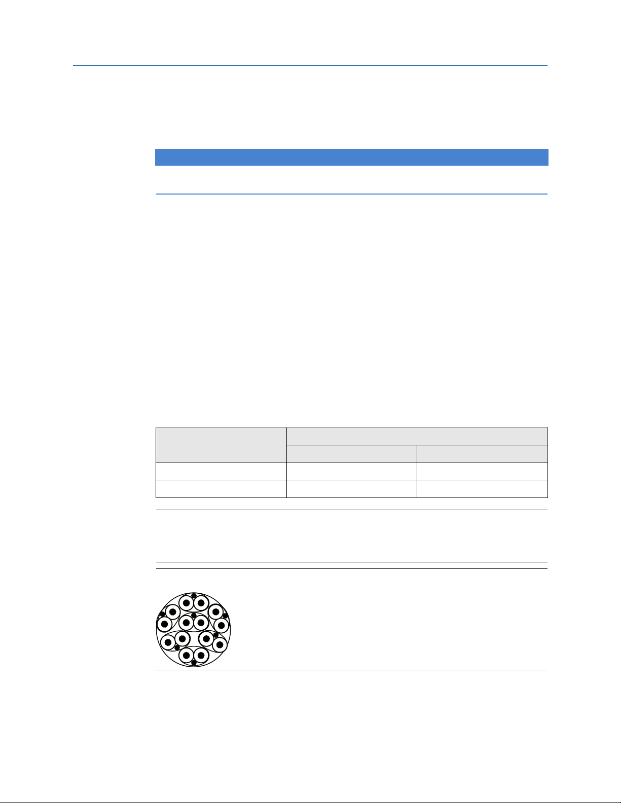
The TRL2 bus requires twisted and shielded pair wiring with a minimum cross-sectional
area of 0.50 mm2 (AWG 20 or similar). The maximum length of the TRL2 bus is
approximately 4 km /13000 ft. The TRL2 field bus can normally use existing cables in the
tank area.
Cable cross-sectional area for the TRL2 wiring should follow the recommendations in Table
3-1.
Table 3-1: Minimum Cable Area for the TRL2 Bus
Maximum distance Cross-sectional area
Minimum Maximum
3 km 0.50 mm2 (AWG 20) 2.5 mm
4 km 0.75 mm2 (AWG 18) 2.5 mm
2
2
Note
Wherever two or more TRL2 buses run alongside each other, sharing the same cable or
conduit tube, use twisted and shielded wire and ensure that each pair of bus wires is
individually shielded in order to avoid crosstalk.
Figure 3-3: Individually Shielded Pair Cables Minimizes Crosstalk
Table 3-2 shows typical cable types that can be used for connecting the TRL2 bus. Other
cables of similar type may also be used.
38 Reference Manual

Reference Manual Installation
00809-0100-2460 September 2021
Table 3-2: Recommended Cable Standards for the TRL2 Bus
Type Manufacturing standard Core size
Signal BS 5308 part 1, type 1 1 mm
Signal (armoured) BS 5308 part 2, type 1 1 mm
2
2
RS485 Bus
The RS485 bus should meet the following requirements:
• twisted and shielded pair wiring
• characteristic impedance of 120 Ω
• maximum cable length 1200 m / 4000 ft at baud rate 9600 bps
Rosemount 2460 System Hub 39

Installation Reference Manual
September 2021 00809-0100-2460
3.5.7 Connecting to a Rosemount 2460 System Hub
There are several ways to connect a Rosemount 2460 System Hub to a host system:
• from a Host Port using TRL2 bus
• from a Host Port using RS232 or RS485
• via Ethernet Eth1 port
The TRL2 Bus requires a twisted and shielded pair cable with a cross-sectional area of 0.50
to 2.5 mm2 (20 to 14 AWG). A Rosemount 2180 Field Bus Modem (FBM) is used to connect
the system hub to TankMaster or other host computer.
A service PC can be connected to the Ethernet Eth3 port for configuration and
maintenance.
For RS232 communication, wiring cross-sectional area must be at least 0.25 mm2 (24
AWG or similar). The typical maximum length of the RS232 connection is 30 m at baud
rate 4800.
Table 3-3: Data Rate and Maximum Distances for RS232 Communication
Baud rate (bps) Distance (m)
2400 60
4800 30
9600 15
19200 7.6
Related information
Terminal board and ports
Communication ports for hosts and field devices
The Rosemount 2460 System Hub has eight ports for communication interface boards. It
is equipped with interface boards for field device communication and host
communication. The specific configuration is specified in the ordering information.
Communication boards can easily be exchanged if needed.
Port 8 is used for TankMaster communication. Port 7 is used for host or TankMaster
communication as specified in the ordering information.
Port 1 to Port 4 are used for field device communication.
Ports 5 and 6 can be used for host or field device communication as specified in the
ordering information. This allows you to vary the number of field and host ports
depending on the specific requirements.
Table 3-4 shows various configuration options for a system hub.
40 Reference Manual

Reference Manual Installation
00809-0100-2460 September 2021
Table 3-4: Port Configuration Options
Ports 1 2 3 4 5 6 7 8
Alternative 6+2
(standard)
Alternative 5+3 Field
Alternative 4+4 Field
Field
Port
Port
Port
Field
Port
Field
Port
Field
Port
Field
Port
Field
Port
Field
Port
Related information
Communication/configuration specifications
Exchanging a modem card
Field
Port
Field
Port
Field
Port
Field
Port
Field
Port
Host
Port
Field
Port
Host
Port
Host
Port
Host
Port
Host
Port
Host
Port
Host
Port
Host
Port
Host
Port
Rosemount 2460 System Hub 41

Installation Reference Manual
September 2021 00809-0100-2460
3.5.8 Wiring
The terminal compartment has a terminal board for connecting communication buses to
host systems and field devices. The terminal compartment also has a connection for
power supply. Ethernet connections are available for LAN communication.
Prerequisites
Note
Ensure that gasket and seats are in good condition prior to mounting the cover in order to
maintain the specified level of ingress protection. The same requirements apply for cable
inlets and outlets (or plugs). Cables must be properly attached to the cable glands.
Procedure
Ensure that the power supply is switched off.
1.
Note
If any uncertainty exists whether power supply is off or not, make sure that loose
cable ends don’t run through the cover on the power board.
2. Loosen the two captive screws and open the lid (see Figure 3-4).
Note
The lid can be removed from the housing for easier access when open more than
25°. Remove the locking ring and carefully slide the lid upwards 21 mm or more. Be
careful not to drop it on the floor.
3. Run wires through a cable gland. Install wiring with a drip loop in such a way that
the lower part of the loop is under the cable entry.
4. Connect wires to the terminal block.
• See Figure 3-5 for information on terminal block bus connections.
• See Wiring diagrams for examples on how to connect the Rosemount 2460 to
various host systems and field devices.
• For wiring of redundant system hubs see Figure 3-18.
5. Use the enclosed metal plugs to seal any unused cable entries.
6. Tighten the conduits/cable glands.
7. Make sure that the Lock ring on the cover to the communication board
compartment is folded so that it does not prevent the lid from being properly
closed.
8.
Attach the lid in case it was removed from the housing and close it. Torque the
two screws to 4 Nm (35 in.-lb). Ensure that it is fully engaged to prevent water from
entering the terminal compartment.
42 Reference Manual

A
E
B
D
C
C
B
Reference Manual Installation
00809-0100-2460 September 2021
Front view
Figure 3-4: Rosemount 2460 Front View
A. Lid
B. Lock ring
C. Captive screws x 2
D. Cover for communication board compartment
E. Power Board
Rosemount 2460 System Hub 43

D
A
C
B
E F G H
RXTXRXTXRXTXRXTXRXTXRXTXRXTXRX
POWER
LED BOARD
TX
Port 1
ETH
1
Port 2 Port 3 Port 4 Port 5 Port 6 Port 7a
Port 7b Port 8b
Port 8a
ETH3ETH
2
WRITE PROT
ON/OFF
SD CARD
SERVICE
I
Installation Reference Manual
September 2021 00809-0100-2460
3.5.9 Terminal board and ports
Figure 3-5: Ports and Terminals
44 Reference Manual
A. TRL2, RS485, ENRAF
B. Other interfaces
C. Write Protection Switch ON/OFF
D. Ethernet 1
E. Ethernet 2
F. Ethernet 3 / Service
G. USB A 2.0
H. SD card
I. Ground bar for cable shield

Reference Manual Installation
00809-0100-2460 September 2021
Table 3-5: Terminal Assignment
Terminal Designation Function
Port 1 Field device Communication bus for field devices.
Port 2
Port 3
Port 4
Port 5 Field device/Host Port 5 and 6 can be configured for field or host communication.
Port 6
Port 7a Host/TankMaster Communication bus for host. Ports designated “a” and “b” are
Port 7b
Port 8a TankMaster Communication bus for TankMaster.
Port 8b
connected in parallel. Supports electrical interface TRL2,
RS485, RS422, and RS232.
Ports designated “a” and “b” are connected in parallel. This
port supports electrical interface TRL2, RS485, RS422, and
RS232.
ETH 1 Standard Ethernet
port
Ethernet communication bus.
ETH1 is used for DCS/host communication via Modbus TCP.
In case the Rosemount 2460 is connected to a Local Area
Network (LAN) via Modbus TCP, ensure the connection is
secure and no unauthorized personnel can grant access.
ETH 2 ETH 2 is an Ethernet communication bus for connection of
redundant system hub. ETH 2 is disabled for standalone
systems, but enabled for connection to redundant pair in
redundant systems.
ETH 3 Service Ethernet communication bus for service purposes. Use this
port to access the Web interface for the 2460.
USB A 2.0 USB Port for USB stick
SD card SD Memory card
(1)
for saving log files.
(1)
reader for saving log files.
Ground bar For connection of cable shields.
(1) USB sticks and SD cards should be FAT32 formatted.
Rosemount 2460 System Hub 45
Pins internally connected in parallel
For daisy chain
Pins internally connected in parallel
(a)
(b)
Installation Reference Manual
September 2021 00809-0100-2460
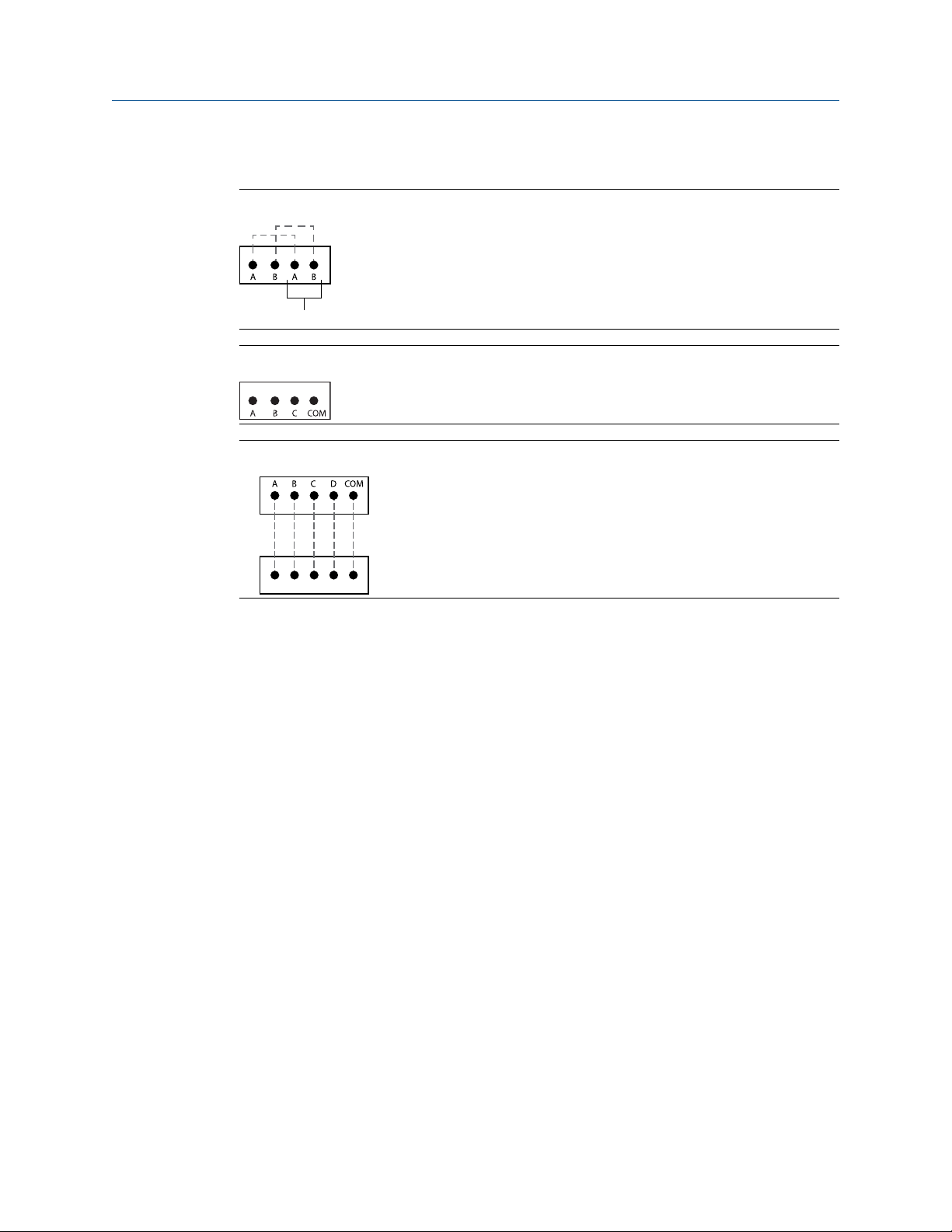
Pin mapping for 4 pole and 5 pole connectors
Figure 3-6: Port 1-6 for TRL2, RS485, and Enraf
Figure 3-7: Port 1-6 for Other Interfaces
Figure 3-8: Port 7-8
Related information
Bus connections
46 Reference Manual

Reference Manual Installation
00809-0100-2460 September 2021
Bus connections
Table 3-6: Bus Connections to Port 1 - 6 Standard
Interface A B A
(1)
TRL2 (A and B polarity independent)
(1)
B
RS485 (2-wire)
A B A B
(Modbus, Whessoe
550/660, GPE)
Internally referenced to
signal ground
Enraf BPM (A and B polarity independent)
(1) For daisy-chain
Table 3-7: Bus Connections to Port 1 - 6 for Emulation
Interface A B C COM
(1)
(1)
Mark Space Power
Computer Encoder Power
+ - Power
Varec Mark/Space
L&J Tankway
Digital Current Loop (DCL
0-20 mA)
(Whessoe 550/660, GPE)
Sakura (V1, MDP, BBB) Loop + Loop - Do not use Do not use
TIC (Tokyo Keiso) X Y Do not use Do not use
(1) External power supply for powering the bus is required
(2) Input voltage maximum 50 Vdc.
(3) External power input (C=+, COM=-). Only used for external loop power. Do not use if Rosemount
2460 System Hub provides loop power.
(2)
(2)
(3)
Signal
ground
Signal
ground
Signal
ground
(2)
(2)
(3)
Table 3-8: Bus connections to Host Port 7- 8
Interface A B C D COM
TRL2 (A and B polarity independent) N/A N/A N/A
RS485 / 422
(2-wire)
(1)
RS485 / 422
(4-wire)
RS232 RxD TxD N/A N/A GND
(1) Recommended for redundant systems
Rosemount 2460 System Hub 47
A B N/A N/A GND
RD + (A’) RD - (B’) TD + (A) TD - (B) GND

A
B
A
Installation Reference Manual
September 2021 00809-0100-2460
Conductors
Ensure that you use cables suitable for the terminal blocks that are supplied by Emerson
for the Rosemount 2460 System Hub.
Table 3-9: Cables Suitable for Terminal Blocks Supplied by Emerson
Conductor connection Maximum (mm2) AWG
Solid 4 11
Flexible 2.5 13
Flexible, Ferrule with plastic collar 1.5 16
Figure 3-9: Conductor Stripping Length and Cross-sectional Area
A. Stripping length: 7 mm
B. Cross-sectional area, see Table 3-9
Figure 3-10: Stripping Length for Connection to Ground Bar
A. Stripping length: 15 mm
48 Reference Manual

2460TAG:
S/N:
MFG (yymmdd):
DEVICE ID:
MAINS: 100-250VAC 50/60Hz, 24-48VDC 20W
A
Reference Manual Installation
00809-0100-2460 September 2021
Cable glands
Figure 3-11: Cable Entries with Glands and External Ground
A. External ground
Table 3-10: Tightening Torque (Nm) for Glands Supplied by Emerson
Item Thread
M20 M25
Body 7 10
Top Nut 4 7
Table 3-11: Cable Diameter (mm) for Glands
Thread
M20 M25
Cable Ø 6 - 13 9 - 17
Rosemount 2460 System Hub 49

C
A
B
10
4
Installation Reference Manual
September 2021 00809-0100-2460
3.5.10 Ground lug
Figure 3-12: Ground Lug Dimensions
A. Ground lug
• Cable lug thickness maximum 4 mm
• Cable lug height maximum 10 mm
B. Cable size minimum 4 mm2 or AWG 11
C. External ground screw M5
50 Reference Manual

L+
N
A
B
Reference Manual Installation
00809-0100-2460 September 2021
3.5.11 Power supply connection
Figure 3-13: Power Supply Connection
A. 24 - 48 Vdc; 100 - 250 Vac; 50 - 60 Hz; Max 20 W
B. Protective ground
Related information
Power supply
Power connector
Note
Connector is of type IEC C16.
Note
Connector is supplied by factory.
Figure 3-14: Power Connector Supplied by Emerson
Note
Use connector type IEC C16 only.
Rosemount 2460 System Hub 51

Installation Reference Manual
September 2021 00809-0100-2460
Table 3-12: Torque Values for Power Connector Assembly
Item Max torque
Terminals 0.8 Nm
Cable clamp 1.2 Nm
Cover 1.2 Nm
Cable size
Table 3-13: Cable and Wire Size for Power Cord
Power cord connector supplied by manufacturer
Wire (x3) Max. 2.1 mm
Cable Max. 10 mm
2
3.5.12 Wiring diagrams
The communication ports can be configured for various combinations of field device and
host communication. In the standard configuration Port1 to Port 6 are connected to field
devices and Port 7 and Port 8 are used for host communication.
52 Reference Manual
A
C
D
D
E
F
G
E
F
B
Reference Manual Installation
00809-0100-2460 September 2021
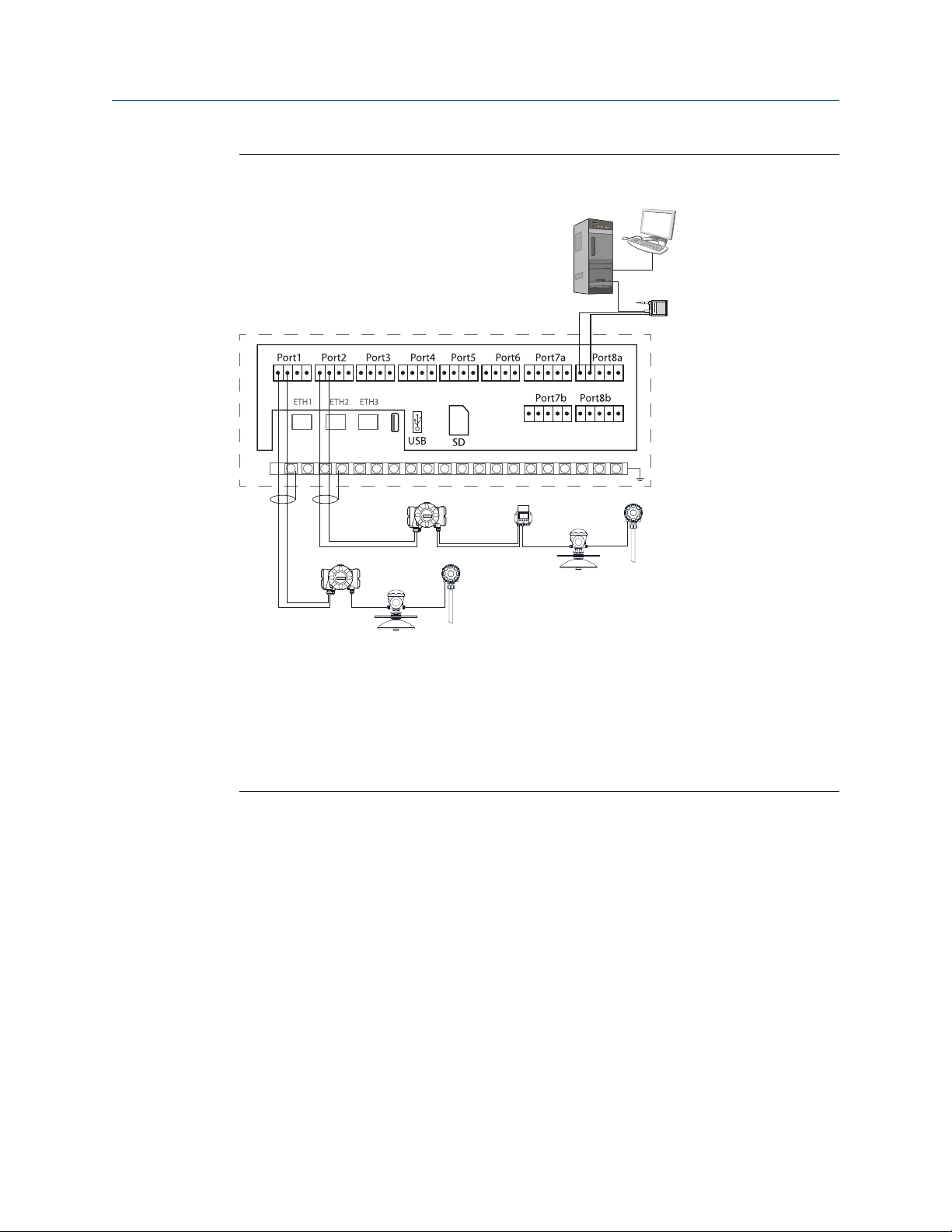
Figure 3-15: Rosemount 2460 System Hub Connected to Field Devices and
TankMaster PC
A. Rosemount TankMaster PC
B. Rosemount 2180 Field Bus Modem
C. Rosemount 2460 terminal board
D. Rosemount 2410 Tank Hub
E. Rosemount 5900S Radar Level Gauge
F. Rosemount 2240S Temperature Transmitter
G. Rosemount 2230 Field Display
Note that the actual Port configuration may differ from the example in Figure 3-15. See
Connecting to a Rosemount 2460 System Hub for more information on configuration
options for the Field and Host ports. See also installation drawings for more information.
Figure 3-16 shows a wiring diagram with a TankMaster host and a Rosemount 2460
connected to field devices from other vendor via ports 1-4.
Rosemount 2460 System Hub 53
C
D
A
B
Installation Reference Manual
September 2021 00809-0100-2460
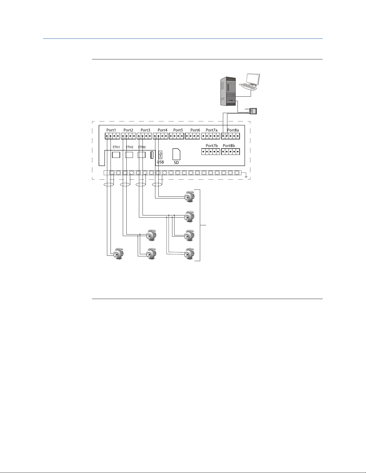
Figure 3-16: Rosemount 2460 with Gauges from Other Vendor
A. Rosemount TankMaster PC
B. Rosemount 2180 Field Bus Modem
C. Rosemount 2460 terminal board
D. Gauges from other vendor
54 Reference Manual

C
B
A
Reference Manual Installation
00809-0100-2460 September 2021
Figure 3-17 shows a wiring diagram with a Rosemount 2460 connected to a host system
via Modbus TCP.
Figure 3-17: Rosemount 2460 Connected to Host System Via Eth 1 Port and Modbus
TCP
A. Host system
B. Modbus TCP
C. Rosemount 2460 terminal board
Rosemount 2460 System Hub 55

A
C
B
D
A
Installation Reference Manual
September 2021 00809-0100-2460
Figure 3-18 shows two system hubs in a redundant system. The Primary and Backup
system hubs are connected to each other via Ethernet port ETH2.
Figure 3-18: Example of Wiring Diagram with Redundant Rosemount 2460 System
Hubs
A. TRL2 bus to host
B. Rosemount 2460 primary unit
C. Ethernet cable for redundancy connection
D. Rosemount 2460 backup unit
56 Reference Manual

A
B
C
D
E
F
Reference Manual Installation
00809-0100-2460 September 2021
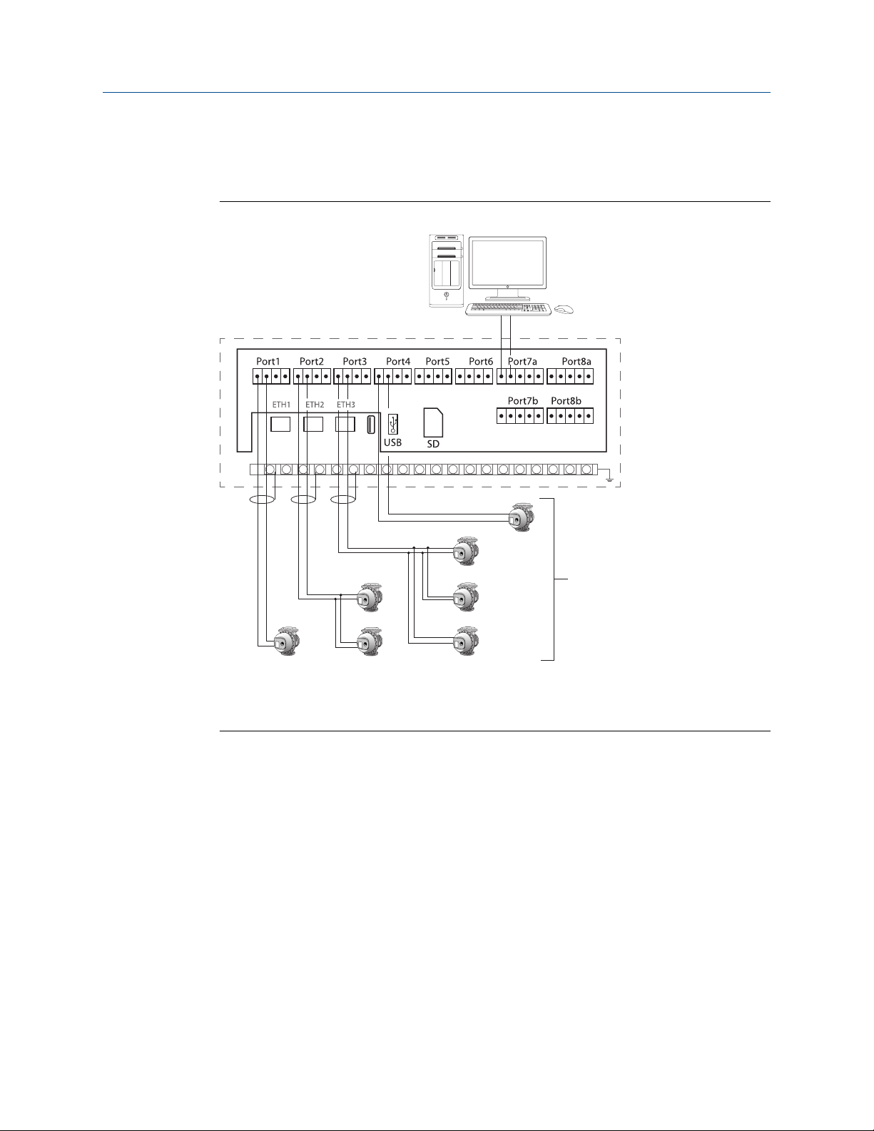
Figure 3-19 shows a wiring diagram with a TankMaster host and a Rosemount 2460
connected to Varec, L&J, and DCL field devices.
Figure 3-19: Rosemount 2460 System Hub Connected to Varec, L&J, and DCL Devices
A. Rosemount TankMaster PC
B. Rosemount 2180 Field Bus Modem
C. Rosemount 2460 terminal board
D. Power: maximum 50 Vdc
E. Varec, L&J, and DCL devices with external power supply (do not use system hub internal
power supply for DCL in this case)
F. DCL devices using system hub internal power supply (do not use external supply in this
case)
Rosemount 2460 System Hub 57
C
B
A
Installation Reference Manual
September 2021 00809-0100-2460
Figure 3-20 shows a wiring diagram with Rosemount 2460 emulating an Enraf CIU 858.
Host port 7 is connected to the Enraf host system. Field ports 1-4 are connected to field
devices.
Figure 3-20: Rosemount 2460 System Hub Connected to Enraf Host System
A. Enraf host system
B. Rosemount 2460 terminal board
C. Enraf field devices
Related information
Electrical installation drawing
Communication ports for hosts and field devices
Terminal board and ports
58 Reference Manual

Reference Manual Configuration
00809-0100-2460 September 2021
4 Configuration
4.1 Overview
This section contains information on how to setup a Rosemount™ 2460 System Hub in a
Rosemount Tank Gauging System. The description is based on using the TankMaster
Winsetup configuration program.
4.2 Safety messages
Instructions and procedures in this section may require special precautions to ensure the
safety of the personnel performing the operations. Information that potentially raises
safety issues is indicated by a warning symbol ( ). Refer to the following safety messages
before performing an operation preceded by this symbol.
WARNING
Failure to follow safe installation and servicing guidelines could result in death or serious
injury.
• Ensure only qualified personnel perform the installation.
• Use the equipment only as specified in this manual. Failure to do so may impair the
protection provided by the equipment.
• Do not perform any service other than those contained in this manual unless you are
qualified.
4.3 Setting up a Rosemount 2460 System Hub
4.3.1 Introduction
A Rosemount 2460 System Hub is easy to install and configure by using the TankMaster
Winsetup configuration program. The WinSetup installation wizard guides you through the
basic configuration to start up a Rosemount 2460.
Host communication via the Ethernet 1 port (ETH1) and Modbus TCP protocol can be
setup by using the Web based Graphical User Interface (GUI).
Related information
Service and troubleshooting
Rosemount 2460 System Hub 59

Configuration Reference Manual
September 2021 00809-0100-2460
4.3.2 Installation procedure
Installation of a Rosemount 2460 System Hub in a Rosemount Tank Gauging system
includes the following basic steps:
Procedure
1. Ensure that a plan is available for all tanks and devices with tag names,
communication addresses, number of temperature elements and other data that is
needed for a system setup.
2. In case devices from other vendors will be connected to the field ports, ensure that
appropriate modem cards are installed which support the communication
protocols. Also, check that the system hub’s firmware supports the modem cards
and protocols. TankMaster 6.C0 and higher is required for configuration of system
hub with Enraf® support. See Specifications and reference data for information on
supported electrical interfaces and protocols. See also Exchanging a modem card.
3. Make sure that the Rosemount 2460 is properly wired and up and running. Check
that the Power LED is on and the Status LED indicates normal operation (see Table
5-3).
4. (Redundancy). Make sure that the two system hubs are properly wired as described
in Wiring. See also Figure 3-18.
Note
Note that configuration of redundant Rosemount 2460 is supported by TankMaster
6.D0 and higher versions.
5. Ensure that the TankMaster WinSetup configuration program is up and running.
6. In TankMaster WinSetup, setup the appropriate protocol channel
(4)
in the
TankMaster host PC. This step will ensure that communication between the
TankMaster PC and the Rosemount 2460 is established.
7. In TankMaster WinSetup, start the device installation wizard and configure the
system hub as described in Installation wizard:
a) Specify device type (2460) and name tag.
b) Check that the correct communication channel is enabled and verify
communication with the TankMaster host computer.
c) Verify that the Host ports and Field ports are using the right protocols for
communication with TankMaster work stations or other host systems, and
with field devices such as the Rosemount 2410 Tank Hub and the Rosemount
5900S Radar Level Gauge.
d) Configure the tank database. See configuration examples that illustrate how
the tank databases of the Rosemount 2460 and the Rosemount 2410 are
related to each other in Tank databases of the Rosemount 2460 and the
Rosemount 2410. Configuration of Enraf devices is covered by section Enraf
device configuration. Configuration of Whessoe WM550/660 devices is
described in Whessoe device configuration.
®
See the Rosemount Tank Gauging System Configuration Manual for more information on how to configure
(4)
communication protocol channels.
60 Reference Manual

Reference Manual Configuration
00809-0100-2460 September 2021
e) (Redundancy). Perform a redundancy configuration in case the system has a
pair of redundant system hubs. This is included as part of the installation
wizard. See Redundancy configuration for more information.
f) Finish the installation wizard and verify that the system hub appears in the
Rosemount TankMaster workspace. Now the Rosemount 2460 will be able to
communicate with the host system and collect data from field devices.
8. In case the Rosemount 2460 communicates with a host system via the Ethernet 1
port and Modbus TCP protocol, open the Web based Graphical User Interface for
configuration as described in Service and troubleshooting.
See the Rosemount Tank Gauging System Configuration Manual (Document no.
00809-0300-5100) for more information on using the TankMaster WinSetup
software to configure a Rosemount Tank Gauging system.
Rosemount 2460 System Hub 61

A
B
F
N
LJ
K
G
M
O
Q
C
E
D
D
C
IH
P
R
Configuration Reference Manual
September 2021 00809-0100-2460
System architecture
Figure 4-1: Rosemount Tank Gauging System Architecture
A. Rosemount TankMaster J. TRL2; Enraf BPM; DCL; RS485
B. Modem K. Ethernet (ETH1)
C. Modbus TCP L. TRL2, RS485
D. Host/DCS M. Gauges and transmitters from other
vendors
E. Plant network N. Rosemount 5900S Radar Level Gauge
F. Rosemount 2460 System Hub O. Rosemount 2240S Temperature
G. Field/Host Ports P. Rosemount 2410 Tank Hub
Transmitter
H. TRL2 Q. Rosemount 2230 Display
I. RS232, RS485 R. Tankbus
62 Reference Manual
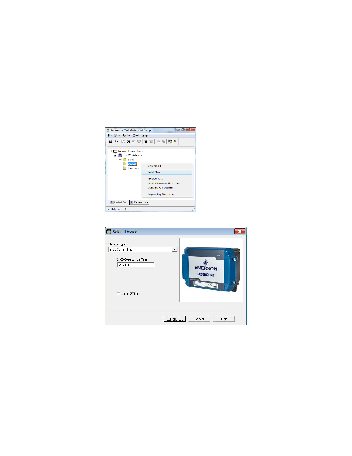
Reference Manual Configuration
00809-0100-2460 September 2021
4.3.3 Installation wizard
This section describes how to install and configure a Rosemount 2460 System Hub by
using the WinSetup installation wizard.
Step 1. Select device type
Procedure
1. In the WinSetup workspace, click the right mouse button on the Devices folder.
2. Select Install new.
3. Select device type:
a) Choose device type 2460 System Hub.
b) Specify a name for the System Hub in the 2460 System Hub Tag input field.
This tag will be used as an identifier of the Rosemount 2460 in various
windows and dialogs. The TankMaster program automatically suggests the
first part of the name as specified in the Tag Prefixes window (Service →
Preferences).
4. Click the Next button to continue the installation procedure with communication
setup.
Rosemount 2460 System Hub 63

Configuration Reference Manual
September 2021 00809-0100-2460
Step 2. Communication setup
Procedure
1. Verify that the correct communication protocol channel is used.
A communication channel needs to be associated with a specific port
(Ethernet/USB/COM) on the TankMaster workstation in order to communicate with
a Rosemount 2460.
2. Verify that the system hub communicates with the TankMaster PC.
The system hub supports many communication interfaces such as Ethernet, TRL2,
RS232, and RS485.
a) To verify communication, enter the system hub’s Modbus Address and click
the Verify Communication button.
The Device ID will appear if the correct Modbus Address was entered (the
Rosemount 2460 is shipped with the default Modbus address=245).
b) In case you would like to change the current Modbus address, or the address
is unknown, click the Change Address on Device button.
Need help?
In case several system hubs are connected using the same default address (245),
you will have to change the addresses of the system hubs before the Verify
command can be used.
3. Click the Next button to continue the installation procedure.
Note
Host communication via the Ethernet 1 port and Modbus TCP must be configured
via the Web based graphical user interface.
64 Reference Manual
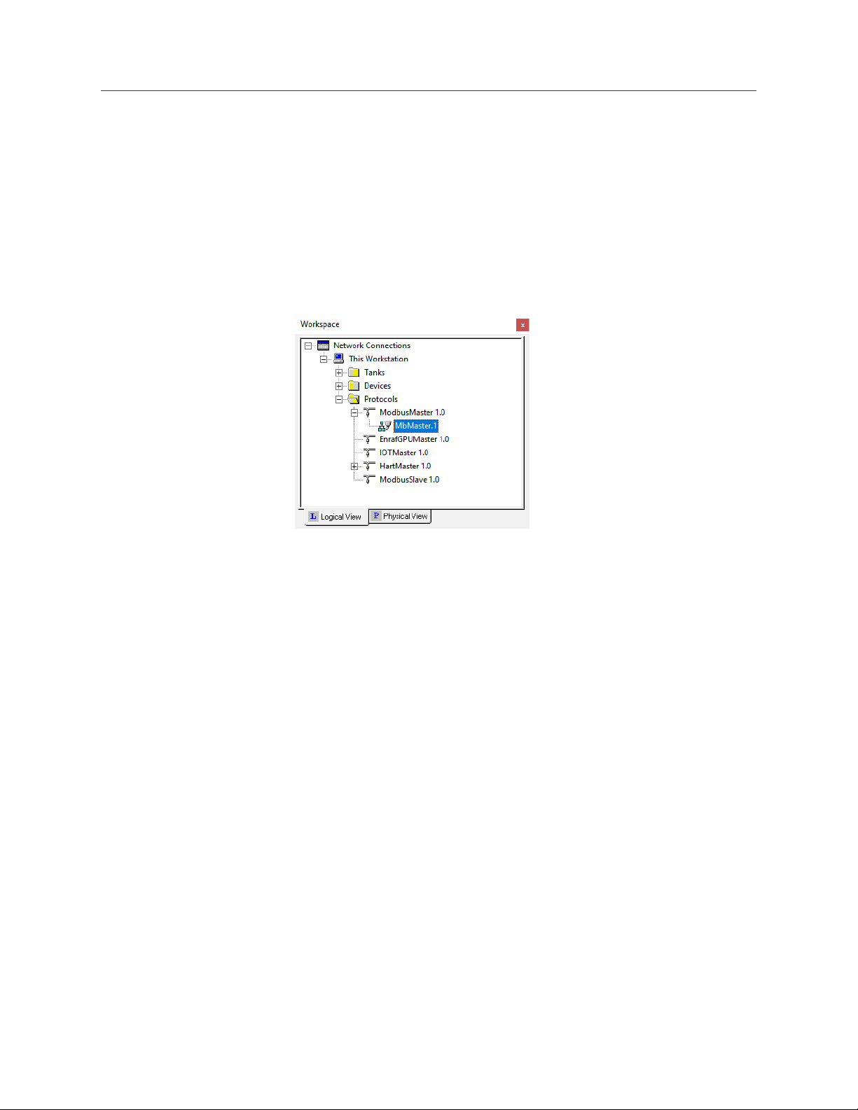
Reference Manual Configuration
00809-0100-2460 September 2021
Related information
Check communication channel properties
Change the system hub’s Modbus address
Check communication channel properties
Procedure
1. To check which channel is enabled:
a) In the WinSetup workspace open the Protocols folder.
b) Expand the master protocol folder (ModbusMaster 1.0 in this example)
c) Check that the appropriate channel is enabled (MbMaster.1 in this example).
Disabled channels do not appear in the protocol folder.
2. To check which communication type that is used:
Rosemount 2460 System Hub 65

Configuration Reference Manual
September 2021 00809-0100-2460
a) Right-click the desired protocol channel icon and select Properties.
b) Open the Communication tab and check which communication channel
type that is selected.
Example
This example shows that Modbus TCP over Ethernet is used for Protocol
Channel 1. The Modbus RTU options means that the system hub
communicates via Host ports.
See the Rosemount Tank Gauging System Configuration Manual (Document
no. 00809-0300-5100) for more information on how to configure
communication protocols.
Change the system hub’s Modbus address
Procedure
1. In the 2460 Communication window, click the Change Address on Device button to
open the Change Address window.
66 Reference Manual

Reference Manual Configuration
00809-0100-2460 September 2021
2. Enter the Device ID and the new Modbus address.
For the Rosemount 2460 System Hub it is recommended to use addresses starting
from 201. When changing the device address, the Device ID is used as a unique
identifier. The Device ID can be found on a label mounted on the device.
Tip
If there is no other device connected that uses the same address as the current
device, you can find the Device ID by typing the address into the Address field in the
Rosemount 2460 System Hub Communication window and clicking the Verify
Communication button.
3. Click the OK button to confirm the settings and close the Change Address window.
4. In the Rosemount 2460 System Hub Communication window click the Verify
Communication button to check if communication is established between the
TankMaster work station and the Rosemount 2460 System Hub.
The Device ID will appear when TankMaster finds the system hub.
Step 3. Port configuration
Procedure
1. Verify that the correct modem (TRL2, RS485, Enraf®, Digital Current Loop (DCL)) is
installed, and communication ports are properly configured.
In most cases there is no need to change any communication parameters. Standard
configuration is automatically set for each modem type. The Advanced button
allows you to change communication parameters in case the standard settings are
not sufficient for specific requirements.
a) Modem. The Rosemount 2460 supports a large number of modem types.
Verify that correct modem is installed on each port to be used.
Rosemount 2460 System Hub 67

Configuration Reference Manual
September 2021 00809-0100-2460
b) Port Type. The Rosemount 2460 has eight communication ports. They are
normally configured as six Field ports and two Host ports. Host ports can be
connected to TankMaster work stations as well as other hosts. The Field ports
are connected to Rosemount 2410 Tank Hubs and other supported field
devices.
c) Protocol. The Modbus protocol is the standard option in Rosemount Tank
Gauging systems. However, other protocols are supported as well. For
protocols which are not automatically detected by the system hub, you may
configure communication protocol and parameters manually by clicking the
Advanced button (see Step 2 below).
d) Settings. Verify the communication parameters.
2. Optional: Communication parameters for Host and Field ports can be configured in
the Advanced Port Configuration window (click the Advanced button).
a) Select the desired protocol and configure the communication parameters.
b) Click the Apply button to save the current configuration.
c) Click the OK button to return to the Rosemount 2460 System Hub
Configuration window.
3. In the Rosemount 2460 System Hub Configuration window, click the Next button to
continue the installation procedure.
Related information
Communication/configuration specifications
Connecting to a Rosemount 2460 System Hub
Default communication parameters
Modem cards
68 Reference Manual

Reference Manual Configuration
00809-0100-2460 September 2021
Advanced port configuration window
The Advanced Port Configuration
configuration to a non-standard configuration. This is a useful option if, for example, the
Rosemount 2460 System Hub is connected to a host system that requires manual port
configuration. Then you can configure protocol and communication parameters to match
the requirements for the host. Non-standard settings may also be needed in case field
devices connected to different field ports use different communication parameters such
as baud rate. Then each port can be configured independently from the other ports.
Non-standard settings may also be required in case the system hub is located far away
from the host since maximum communication speed for RS232 and RS485 depends on
the cable length.
Some emulation protocols use the same type of modem card. Therefore, you may need to
specify communication protocol and configure parameters for the particular protocol to
be used.
(5)
window lets you change from standard port
Reply timeout
and Number of
retries
Min/max
response time
Min Rx to Tx
delay time
Single Port
Mode
Redundant
field ports
For Field Ports the Reply timeout and Number of retries parameters
can be adjusted in case a connected field device responds slowly to
queries from the Rosemount 2460. The default setting is sufficient in
most cases.
For Host Ports the Min response time and Max response time define
the time slot in which a response from the Rosemount 2460 will be sent
to a host system. If needed, you may change these parameters to
match the requirements for a particular host system.
For field ports a delay time between receive and transmit messages can
be used for devices that need more time to get ready to receive the
next query e.g. TIC devices.
In case of cross talks between field port buses, it is possible to configure
affected ports to be silent while communication is ongoing on a port in
single port mode. For the configuration to have an effect, two or more
field ports must be enabled for Single Port Mode. If all field ports are
enabled for Single Port Mode, no concurrent communication among
the field ports can occur at all. This configuration has no effect if the
Port is configured for host mode which is an option for ports 5 and 6.
The Redundant Field Ports functionality is supported for TRL2 and
RS485 interface and requires license for redundant system hubs. Two
field ports can be configured in a redundant primary/backup pair. If the
primary port has communication problems, the backup port will take
over after a number of retries.
Status of the passive port is checked at regular intervals. A switch over
to backup port will only take place if status of the backup port is OK. If
the backup port is active, and primary port status is back to normal, a
switch over will take place once the status check is done.
Redundant field ports can be used with redundant Rosemount 2460
System Hubs.
(5) Some modems must be configured with DIP switches.
Rosemount 2460 System Hub 69

Configuration Reference Manual
September 2021 00809-0100-2460
Related information
Modem cards
Default communication parameters
Table 4-1: Modbus Communication Parameters for Rosemount 2460 Host Ports
Interface Parameters
Baud rate Data bits per
character
TRL2 4800 8 1 None
RS485 9600 8 1 None
RS232 19200 8 1 None
Stop bits Parity
Table 4-2: Communication Parameters for Rosemount 2460 Field Ports
Interface Parameters
Baud rate Data bits per
character
TRL2 4800 8 1 None
RS485 9600 8 1 None
Enraf BPM 1200 7 1 Odd
Digital Current
Loop
Varec Mark/Space 250 8 1 None
L&J Tankway 1200 8 1 Even
TIC 2400 8 1 Even
Sakura 9600 8 1 None
2400 8 1 Even
Stop bits Parity
GPE 300 7 1 Odd
Related information
Digital communication protocols
Step 4. Configure the tank database
The tank database of the Rosemount 2460 System Hub ensures that the system hub
requests information from all the connected field devices.
Procedure
1. Find a free tank position (2460 Tank 1, 2, 3...) for the device to be configured.
70 Reference Manual

Reference Manual Configuration
00809-0100-2460 September 2021
2. Select the appropriate Source device.
For a Rosemount Tank Gauging system this is typically a Rosemount 2410 Tank
Hub. The Rosemount 2460 System Hub also supports many other Rosemount Tank
Gauging devices as well as devices from other vendors.
3. Select the Field Port that the device is connected to.
In the standard configuration there are six field bus ports available for a Rosemount
2460 System Hub. The TRL2 bus is the standard field bus interface.
4. Enter the 2410 Device Address for each Rosemount 2410 Tank Hub that is
connected to the system hub.
Note
Note that for 2410 Tank Position 1 the same address will be used for the
temperature device and the tank hub itself. This is handled automatically by
TankMaster.
5. Enter the appropriate 2410 Tank Position.
All field devices on a certain tank are associated with the same position in the
Rosemount 2410 Tank Hub’s tank database. For a Rosemount 2410 connected to a
single tank, all field devices are configured in Tank Position 1.
Use Tank Position 2-10 for the multiple tanks version of the Rosemount 2410 Tank
Hub. It has a database with 10 tank positions that allows the tank hub to serve up to
ten tanks. Each row in the tank database of the Rosemount 2460 System Hub
corresponds to a tank position in the database of the Rosemount 2410 Tank Hub.
Important
The Tank Database of the Rosemount 2460 System Hub must be properly
configured to match the tank databases of all Rosemount 2410 Tank Hubs
connected to the system hub.
6. Enter Level Device Address for devices such as the Rosemount 5900 Radar Level
Gauge and other level gauges supported by the Rosemount 2460 System Hub and
the Rosemount 2410 Tank Hub.
7. In case the level gauge is a Rosemount 5900S 2-in-1 version, you will need to
configure two level device addresses.
See the Rosemount Tank Gauging System Configuration Manual (Document No.
00809-0300-5100) for a detailed description of how to configure the tank database
for a Rosemount 5900S Radar Level Gauge 2-in-1 version.
Rosemount 2460 System Hub 71

Configuration Reference Manual
September 2021 00809-0100-2460
8. Enter the Temperature Device Address.
For “2410 tank position” 1 the same address is used for the Rosemount 2410 Tank
Hub and the temperature device. The tank hub’s address is automatically copied to
the Temperature Device Address field.
For “2410 Tank Position” 2 to 10 you will have to enter the same temperature
device addresses as configured in the Rosemount 2410 Tank Hub’s tank database.
Each tank position must have a unique address.
Note
The Temp Device Address in the Rosemount 2460’s tank database is referred to as
the ATD Modbus Address in the Rosemount 2410 Tank Hub’s tank database.
9. Enter the number of elements in the Number of Temperature Elements column in
case temperature elements are installed in the tank.
The position of the temperature elements need to be configured to allow
calculation of average product temperature. This is normally done as part of the
standard installation procedure for the Rosemount 2410 Tank Hub and the
associated temperature transmitters as described in the Rosemount Tank Gauging
System Configuration Manual (Document no. 00809-0300-5100).
10. Select the Auxiliary Inputs that are used for the device such as Free Water Level
(FWL), Vapor Pressure (VP), and Liquid Pressure (LP).
11. In the Relays column, select 2410 if a Rosemount 2410 Tank Hub with relay output
is connected to the Rosemount 2460 System Hub. Then the 2460 input registers
will be continuously updated with current status of the 2410 relay outputs. Leave
empty if no relays are used.
Note
Ensure that the Tank Database is properly verified before proceeding. Check all
addresses and parameters for each tank and source device.
Related information
Tank database entry fields
Connecting to a Rosemount 2460 System Hub
Tank databases of the Rosemount 2460 and the Rosemount 2410
Enraf device configuration
Whessoe device configuration
L&J device configuration
Varec device configuration
TIC configuration
Sakura configuration
NRF590 configuration
Tank database configuration
The tank database of the Rosemount 2460 System Hub ensures that the system hub
requests information from all the connected field devices. It is very important that the
Tank Database of the Rosemount 2460 System Hub is properly configured to allow
communication between the Rosemount 2460, the Rosemount 2410 Tank Hub, and field
72 Reference Manual

Reference Manual Configuration
00809-0100-2460 September 2021
devices such as the Rosemount 5900S Radar Level Gauge, the Rosemount 2240S MultiInput Temperature Transmitter, pressure transmitters, and other field devices supported
by the system hub.
Figure 4-2: Tank Database
Note
Once all devices and tanks are installed and configured, the position of a device in the Tank
Database may not be changed, since this will result in corrupt mapping of tank to Tank
Database position.
Level device address
The Level Device Address field in the tank database of the Rosemount 2460 System Hub is
used for level gauges such as the Rosemount 5900. This address also needs to be stored in
the tank database of the Rosemount 2410 Tank Hub.
Normally, address configuration is done as part of the installation procedure of the
Rosemount 2410 as described in the Rosemount Tank Gauging System Configuration
Manual (Document No. 00809-0300-5100).
Temperature device address
The Temperature Device Address in the tank database of the Rosemount 2460 System Hub
is a common address for all devices (ATD) on a tank except level gauges. The Temperature
Device address also needs to be stored in the tank database of the Rosemount 2410 Tank
Hub. For the tank hub this address is referred to as the ATD Modbus address.
Configuration of the Rosemount 2410 tank database is normally done as part of the
installation procedure of the Rosemount 2410 as described in the Rosemount Tank
Gauging System Configuration Manual (Document No. 00809-0300-5100).
Rosemount 2460 System Hub 73

Configuration Reference Manual
September 2021 00809-0100-2460
For the first tank position in the Rosemount 2410 tank database, the Rosemount 2410
Modbus address is automatically set as the ATD Modbus address.
It is recommended that address range 1 to 99 is used for level gauges and 101 to 199 for
ATD devices.
See also section “Installing a Rosemount 2410 Tank Hub” in the Rosemount Tank Gauging
System Configuration Manual (Document No. 00809-0300-5100).
Related information
Tank databases of the Rosemount 2460 and the Rosemount 2410
Tank database entry fields
Table 4-3: Entry Fields for the Tank Database
Entry field Description
Source • 2410 Tank Hub
• Rex
• Rex + DAU
• Pro
• Pro + DAU
• TRL2 RTG
• TRL2 RTG + DAU
• Enraf
• Whessoe
• L&J
• Varec
• TIC
• Sakura
(1)
(811, 813, 854, 873, 894, 970, 971, TOI-B)
(2)
(550, 660)
(3)
(MCG 2000, MCG 1500XL)
(3)
(1800, 1900)
Field port
2410 Device Address Modbus address for the connected Rosemount 2410 Tank Hub.
2410 Tank Position Each tank is associated with a certain position in the tank database of
Level Device Address Communication address for the connected level device.
Temperature Device
Address
74 Reference Manual
The field bus port that the selected device is connected to. Up to six
field ports may be used.
Address range 101 to 199 is recommended.
the Rosemount 2410 Tank Hub. Devices on a tank must be
configured with a tank position that refers to the actual tank where
the device is installed.
For level gauges address range 1 to 99 is recommended.
Communication address for the connected Temperature/ATD
device.
For Temperature/ATD devices address range 101 to 199 is
recommended.

Reference Manual Configuration
00809-0100-2460 September 2021
Table 4-3: Entry Fields for the Tank Database (continued)
Entry field Description
Number of Temperature
Elements
(1) Enraf option is supported for Rosemount 2460 firmware version 1.B0 and higher .
(2) Whessoe option is supported for Rosemount 2460 firmware version 1.D0 and higher.
(3) L&J and Varec options are supported for Rosemount 2460 firmware version 1.E0 and higher
Number of temperature elements connected to the temperature
transmitter (for example a Rosemount 2240S Multi-Input
Temperature Transmitter).
Related information
Communication ports for hosts and field devices
Enraf device configuration
Whessoe device configuration
L&J device configuration
Varec device configuration
TIC configuration
Sakura configuration
Tank Database entry fields Auxiliary inputs
Table 4-6: Entry fields for Rosemount 2410
Entry field Description
2410 Tank Hub
• Vapor Pressure
• Middle Pressure
• Liquid Pressure
• Free Water Level
• User Inputs 1 - 5
• Relays
• Delta Level (Uin=DL, tank position 1 only)
Table 4-7: Entry fields for Enraf
Entry field Description
Enraf Enraf
(1) Enraf option is supported for Rosemount 2460 firmware version 1.B0 and higher.
Rosemount 2460 System Hub 75
(1)
• Vapor Pressure
• Middle Pressure
• Liquid Pressure
• Free Water Level
• Observed Density (UIn1=Dens)

Configuration Reference Manual
September 2021 00809-0100-2460
Table 4-8: Entry fields for Whessoe
Entry field Description
Whessoe Whessoe 550
• Vapor Pressure
• Liquid Pressure
(1)
(2)
(2)
Whessoe 660
• None
(1) Whessoe option is supported for Rosemount 2460 firmware version 1.D0 and higher.
(2) Vapor or Liquid pressure can be selected, not both.
Table 4-9: Entry fields for Varec
Entry field Description
Varec Varec
(1)
• None
(1) L&J and Varec options are supported for Rosemount 2460 firmware version 1.E0 and higher.
Table 4-10: Entry fields for L&J
Entry field Description
L&J L&J
(1)
• Vapor Pressure
• Liquid Pressure
• Free Water Level
• Observed Density (UIn1=Dens)
(1) L&J and Varec options are supported for Rosemount 2460 firmware version 1.E0 and higher.
Table 4-11: Entry fields for TIC
Entry field Description
TIC TIC
• Observed Density
Table 4-12: Entry fields for Sakura
Entry field Description
Sakura Sakura BBB/MDP
• None
76 Reference Manual

Reference Manual Configuration
00809-0100-2460 September 2021
Table 4-12: Entry fields for Sakura (continued)
Entry field Description
Sakura V1
• Vapor Pressure
• Middle Pressure
• Liquid Pressure
• Free Water Level
• Observed Density
• User Inputs 1 - 3
Related information
Communication ports for hosts and field devices
Enraf device configuration
Whessoe device configuration
L&J device configuration
Varec device configuration
TIC configuration
Sakura configuration
Rosemount 2460 System Hub 77

Configuration Reference Manual
September 2021 00809-0100-2460
Tank database entry fields Advanced
Table 4-13: Entry fields for the Tank Database Advanced
Entry field Description
Advanced Rosemount 2410
• Average Product Temperature
• Average Product and Vapor Temperature
(1)
Enraf
• Vapor temperature
• Fast polling
Whessoe 550
• Fast polling
Whessoe 660
• Vapor temperature
Varec
• Level range
• Fast polling
(3)
L&J
• Inverse Temperature Sign
• Swap Interface and Pressure
• No Response if Invalid Level
• Fast polling
TIC
• Average Product Temperature
• Advanced Fast polling
Sakura BBB/MDP
• Advanced Fast polling
Sakura V1
• Average Product temperature
• Average Product and Vapor temperature
• Advanced Fast polling
(2)
(3)
(1) Enraf option is supported for Rosemount 2460 firmware version 1.B0 and higher.
(2) Whessoe option is supported for Rosemount 2460 firmware version 1.D0 and higher.
(3) L&J and Varec options are supported for Rosemount 2460 firmware version 1.E0 and higher.
Related information
Communication ports for hosts and field devices
Enraf device configuration
Whessoe device configuration
78 Reference Manual
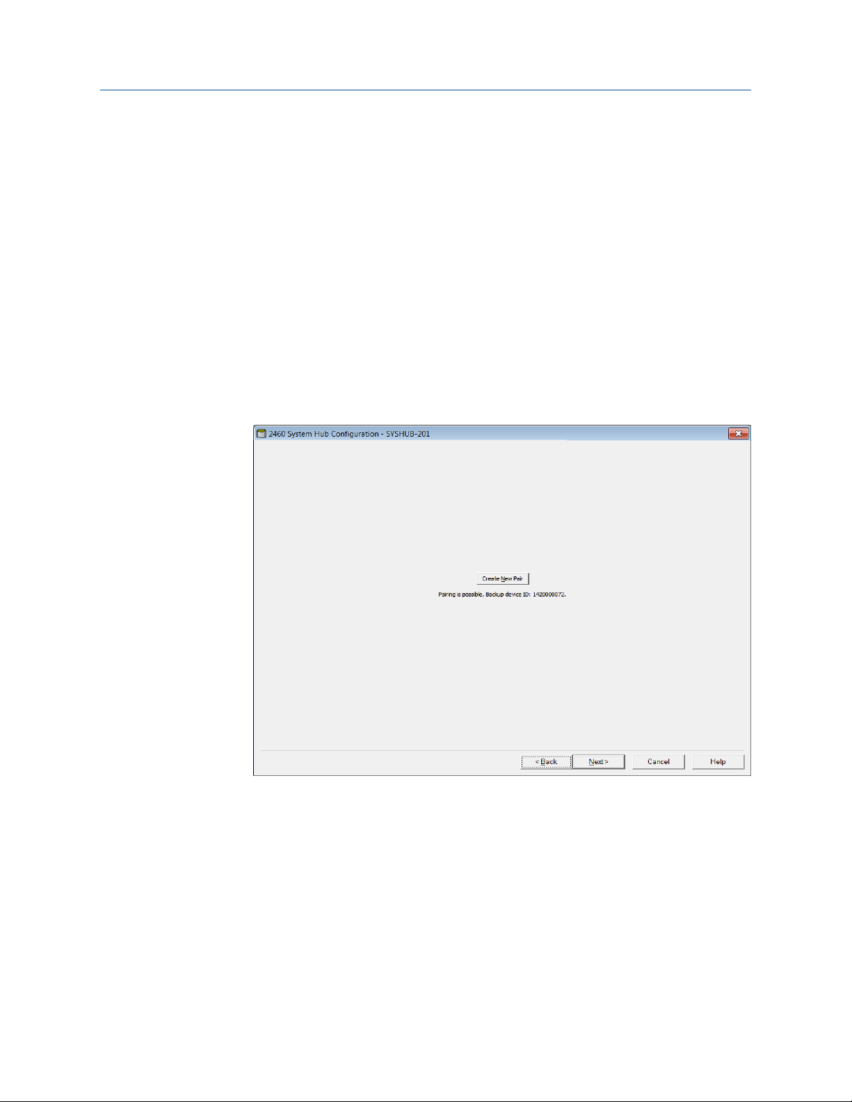
Reference Manual Configuration
00809-0100-2460 September 2021
L&J device configuration
Varec device configuration
TIC configuration
Sakura configuration
Step 5. Redundancy
This step lets you setup a redundant pair of system hubs.
Procedure
1. Click the Create New Pair button to start the redundancy synchronization
procedure. When finished, a message appears that the database synchronization
was successfully completed. The system hubs will be paired as a Primary and a
Backup device.
For standalone system hubs, click Next to skip this step and proceed with Step 6.
Finish the installation.
2. See Redundancy configuration for more information.
Rosemount 2460 System Hub 79
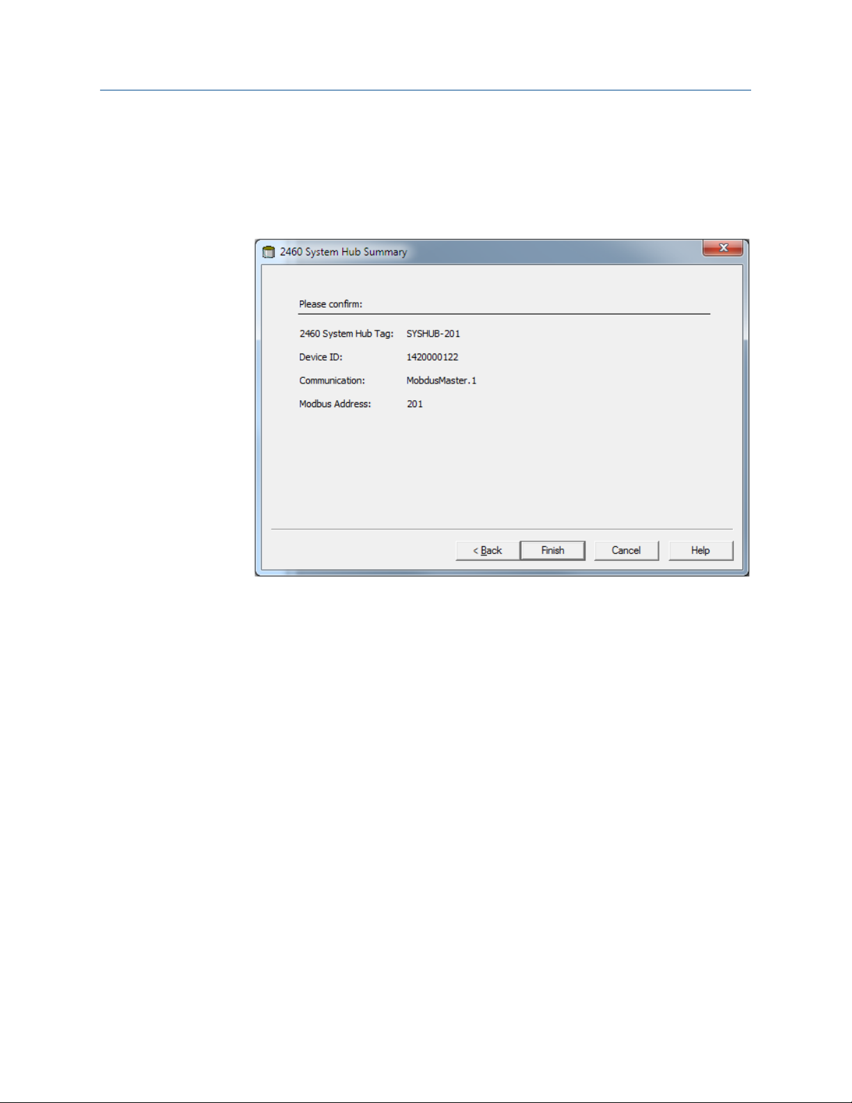
Configuration Reference Manual
September 2021 00809-0100-2460
Step 6. Finish the installation
Procedure
1. Verify that the Tag, Device ID, communication channel, and Modbus Address
presented in the 2460 System Hub Summary window are correct.
2. In case you would like to make any changes in the preceding steps, click the Back
button until the desired window appears.
3. Click the Finish button to confirm the installation.
80 Reference Manual

Reference Manual Configuration
00809-0100-2460 September 2021
4. Verify that the Rosemount 2460 System Hub appears in the TankMaster workspace
window.
Figure 4-3: Rosemount 2460
Figure 4-4: Redundant Rosemount 2460
Now the system hub will be able to communicate with the host system and collect
data from the field devices.
Postrequisites
Proceed with installation and configuration of Rosemount 2410 Tank Hubs and field
devices. See the Rosemount Tank Gauging System Configuration Manual (Document No.
00809-0300-5100) for more information.
4.3.4
Tank databases of the Rosemount 2460 and the Rosemount 2410
In a typical Rosemount Tank Gauging system, a Rosemount 2460 System Hub collects
measurement data from a number of tanks via one or more Rosemount 2410 Tank Hubs.
For proper communication with the control room PC and the Rosemount TankMaster
operator’s interface, Modbus addresses need to be assigned to the field devices on the
tank. These addresses are stored in the system hub’s and tank hub’s tank databases.
Rosemount 2460 System Hub 81

Configuration Reference Manual
September 2021 00809-0100-2460
In the tank hub’s database, the Rosemount 2240S Temperature Transmitter and the
Rosemount 2230 Graphical Field Display (and other non-level devices) are handled as a
single Auxiliary Tank Device (ATD). Two Modbus addresses are used for each tank, one for
the level gauge and one for the ATD.
The ATD includes any supported non-level device such as the Rosemount 2240S MultiInput Temperature Transmitter and the Rosemount 2230 Graphical Field Display. Other
devices such as the Rosemount 3051S Pressure Transmitter may also be included in the
ATD. The ATD address represents all these devices. Each position in the Rosemount 2460
tank database represents one tank.
In case the level gauge is a Rosemount 5900S 2-in-1, you will need to configure two level
device addresses for the Rosemount 5900S gauge. See the Rosemount Tank Gauging
System Configuration Manual (Document No. 00809-0300-5100) for a detailed
description of how to configure the tank database with a Rosemount 5900S 2-in-1.
One Rosemount 2410 Tank Hub for each tank
In this example a Rosemount 2460 System Hub is connected to two tanks, each of which
has a separate Rosemount 2410 Tank Hub.
Each tank has a Rosemount 5900S Radar Level Gauge, a Rosemount 2240S Multi-Input
Temperature Transmitter, and a Rosemount 2230 Graphical Field Display. The Modbus
address configuration is summarized in Table 4-14.
Table 4-14: Example of Modbus Address Configuration for Rosemount 2410 Tank
Hubs and Connected Devices on Two Tanks
Tank Rosemount 2410 Tank
Hub
TK-1 101 1 101
TK-2 102 2 102
Rosemount 5900S Level
Gauge
Modbus Address
ATD (2230, 2240S)
For each tank, the Level Device address and ATD Modbus address in the Rosemount 2460
System Hub’s tank database must be equal to the corresponding addresses in the
Rosemount 2410 Tank Hub’s tank database.
82 Reference Manual

A
B
C
D
E
TK-1
TK-2
B
C
D
E
Reference Manual Configuration
00809-0100-2460 September 2021
Figure 4-5: Two Tanks Each of which Equipped with a Rosemount 2410 Tank Hub
A. Rosemount 2460 System Hub
B. Rosemount 2410 Tank Hub
C. Rosemount 2230 Graphical Field Display
D. Rosemount 5900S Level Gauge
E. Rosemount 2240S Temperature Transmitter
Figure 4-6: Tank Databases in System Hub and Tank Hubs
A. Rosemount 2410 Tank Hub on tank TK-1
B. Rosemount 2460 System Hub
C. Rosemount 2410 Tank Hub on tank TK-2
Rosemount 2460 System Hub 83

Configuration Reference Manual
September 2021 00809-0100-2460
Multiple tanks connected to a single Rosemount 2410 Tank Hub
In this example a Rosemount 2460 System Hub is connected to a Rosemount 2410 Tank
Hub that serves three tanks. The temperature device on tank 1 has the same Modbus
address as the tank hub itself. The other temperature devices on tank 2 and 3 have
separate Modbus addresses.
Figure 4-7 shows an example of a system with a Rosemount 2460 System Hub connected
to a Rosemount 2410 Tank Hub. The Rosemount 2410 collects measurement data from
three tanks. Each tank is equipped with a Rosemount 5408 Radar Level Transmitter, a
Rosemount 2240S Temperature Transmitter, and a Rosemount 2230 Graphical Field
Display. The Modbus address configuration is summarized in Table 4-15.
Table 4-15: Modbus Address Configuration for Tank Hub and Field Devices on Three
Tanks
Tank Rosemount 2410 Tank
Hub
TK-1 101 1 101
TK-2 101 2 102
TK-3 101 3 103
Rosemount 5408 Level
Transmitter
Modbus Address
ATD (2230, 2240S)
Note that each ATD has its own Modbus address. Only the first one has the same address
as the Rosemount 2410 Tank Hub.
84 Reference Manual

A
B
C
D
E
TK-1
TK-2
TK-3
Reference Manual Configuration
00809-0100-2460 September 2021
Figure 4-7: Three Tanks Connected to a Single Rosemount 2410 Tank Hub
A. Rosemount 2460 System Hub
B. Rosemount 2410 Tank Hub
C. Rosemount 2230 Graphical Field Display
D. Rosemount 5408 Level Transmitter
E. Rosemount 2240S Temperature Transmitter
In the tank database of the Rosemount 2410 Tank hub, the Rosemount 2240S
temperature transmitter and the Rosemount 2230 display are grouped into an Auxiliary
Tank Device (ATD). The ATD Modbus address has to be stored in the Temperature Device
address field in the tank database of the Rosemount 2460 System Hub as illustrated in
Figure 4-8. The Modbus addresses of the level devices must also be stored in both the
2410 and the 2460 tank databases.
Rosemount 2460 System Hub 85

Configuration Reference Manual
September 2021 00809-0100-2460
Figure 4-8: Tank Databases in System Hub and Tank Hubs
A. Tank Database for a Rosemount 2410 Tank Hub that serves three tanks
B. Rosemount 2460 System Hub
C. Level device address
D. Auxiliary Tank Device (ATD) address
Note that in this example a single Rosemount 2410 Tank Hub serves three tanks. The tanks
are mapped to tank position 1, 2, and 3 in the Rosemount 2410 Tank Hub’s tank database.
In the tank database of the Rosemount 2460 System Hub, you will have to configure 2410
Tank Position in order to be able to configure the correct Temperature Device Addresses
for the three tanks.
86 Reference Manual
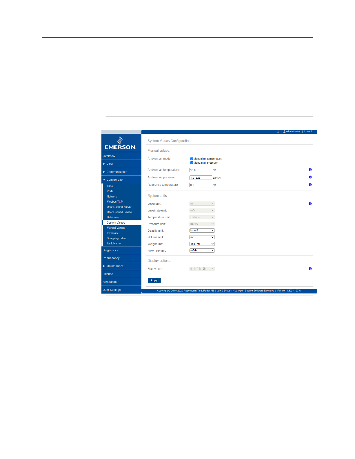
Reference Manual Configuration
00809-0100-2460 September 2021
4.3.5 System setup
The System Values window lets you specify parameters and units for inventory calculations.
Procedure
1. Log in to the Web interface.
2. Select Configuration → System Values.
Figure 4-9: System Parameters and Units
Related information
Logging in to the web interface
Manual values
Select the appropriate check boxes in case you like to use manual values for ambient air
temperature and pressure, and type the desired values into the input fields.
Reference temperature
The Rosemount 2460 System Hub performs inventory calculations according to the API
Manual of Petroleum Measurement Standards Chapter 12, Section 1, at the standard
reference temperature 15°C (60°F). This is the default reference temperature.
Other reference temperatures can be specified in the Reference Temperature input field.
Ensure that correct RT volume table, for example 54B-2004, is used for the product.
Rosemount 2460 System Hub 87

Configuration Reference Manual
September 2021 00809-0100-2460
System units
Level, Level Rate, Temperature, and Pressure units are configured in TankMaster WinSetup
configuration program.
Display options for Feet unit
In case Feet is selected as measurement unit for Level, the Feet Display option lets you
choose the desired display option. You may choose to present as decimal or fraction: ft' in''
1/16 in.
88 Reference Manual

Reference Manual Configuration
00809-0100-2460 September 2021
4.3.6 Redundancy configuration
Setting up a redundant pair of Rosemount 2460 System Hubs can be performed by using
TankMaster WinSetup or the system hub’s Web Graphical User Interface.
Related information
Redundancy setup in TankMaster WinSetup
Redundancy setup via Web graphical user interface
Preconditions for redundancy setup
The following conditions must be met to allow setting up two Rosemount 2460 System
Hubs for redundancy operation:
• The same firmware version on both System Hubs
• Firmware version 1.C0 or higher
• Rosemount TankMaster version 6.D0 or higher
• For Modbus TCP; Rosemount TankMaster version 6.F0 or higher
• No warnings or errors
• License;
— the same maximum number of tanks
— redundancy option enabled on both system hubs
— the same number of Modbus TCP clients
• The same modem board setup
locations)
• Hardware write protection disabled
• Software write protection disabled
Basically all model codes except Housing, Cable/Conduit Connections, and Options
need to be identical for the Primary and Backup system hubs.
(6)
(number of boards, modem type, and modem
(6) Modem boards supported for redundancy: TRL2 Modbus, RS485, Enraf BPM
Rosemount 2460 System Hub 89
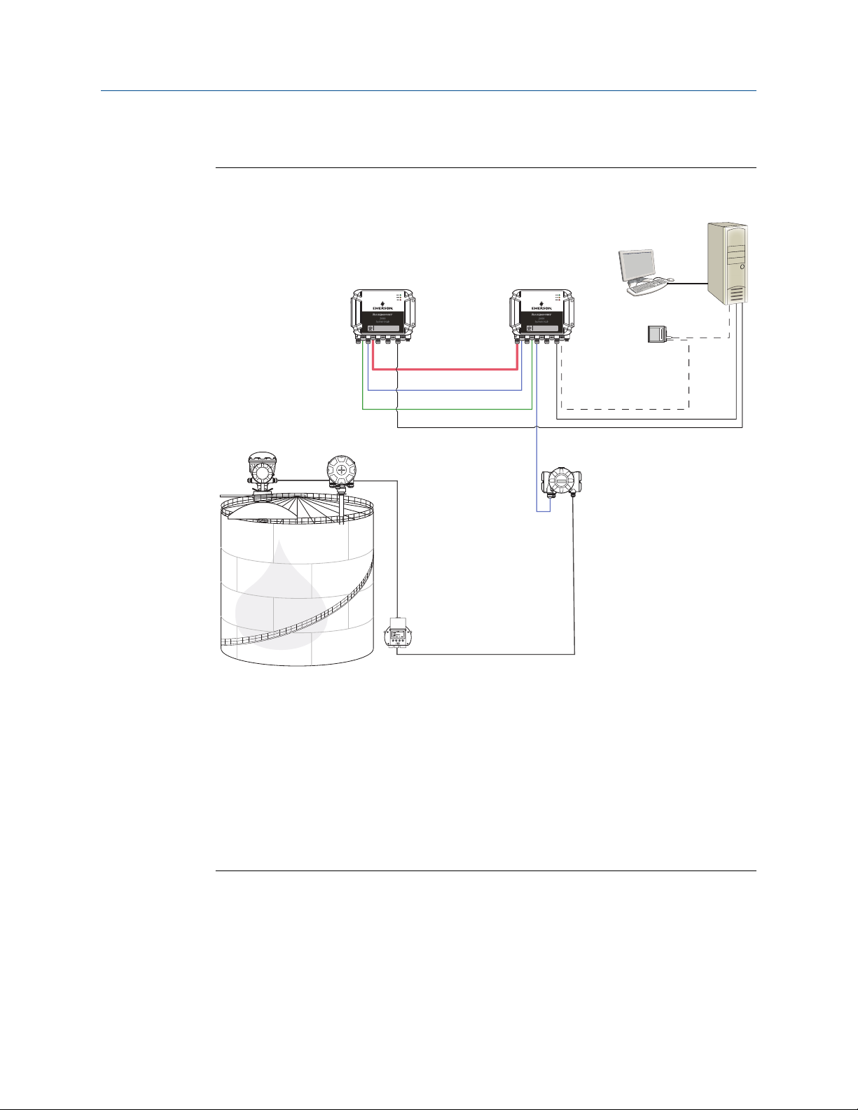
C
D
A B
E
J
K
M
L
G
H I
F
G
Configuration Reference Manual
September 2021 00809-0100-2460
System Architecture with redundant system hubs
Figure 4-10: Rosemount Tank Gauging System Architecture with Redundant System
Hubs
A. Rosemount 2460 System Hub (backup) H. Modbus TCP (Primary)
B. Rosemount 2460 System Hub (primary) I. Modbus TCP (Backup)
C. Host System J. Rosemount 5900S Radar Level Gauge
D. Modem K. Rosemount 2240S Temperature
E. Redundancy cable L. Rosemount 2230 Display
F. Field Ports M. Rosemount 2410 Tank Hub
G. Host Ports
Transmitter
90 Reference Manual

Reference Manual Configuration
00809-0100-2460 September 2021
Redundancy setup in TankMaster WinSetup
This section describes the redundancy setup in the WinSetup configuration wizard for the
Rosemount 2460 System Hub.
Prerequisites
The installation wizard for the Rosemount 2460 includes the option to setup a redundant
pair of Rosemount 2460 System Hubs as long as certain conditions are fulfilled. In case all
requirements for pairing are fulfilled, the following text appears: “Pairing is possible,
Backup device ID:xx”.
Figure 4-11: Redundancy Page in WinSetup Installation Wizard
Procedure
Click the Create New Pair button to start the redundancy synchronization procedure.
Figure 4-12: Redundancy Pairing
When finished, a message appears that the database synchronization was successfully
completed. The system hubs will be paired as a Primary and a Backup device.
Rosemount 2460 System Hub 91

Configuration Reference Manual
September 2021 00809-0100-2460
Redundancy window
Once the synchronization process is successfully finished, the Redundancy window
presents the current status and other information for the two system hubs.
Figure 4-13: Redundant System Hubs
92 Reference Manual

Reference Manual Configuration
00809-0100-2460 September 2021
Table 4-16: Redundancy Configuration
Item Description
Manual Switch Over
button
State If the status is OK, a green check box is displayed. Otherwise a list of
Device ID Each device has a unique identification number which can be used, for
Individual Modbus
address
Recent events Number of times that the Primary and Backup devices have changed to
Switch to standalone
mode button
Configure button This button lets you configure specific redundancy options such as fail-
Active/Passive mode can be changed manually. The Active device
communicates with the host system and responds to requests for
measurement data, status information, and diagnostics. This option
can be useful for testing that both system hubs function properly as
Active and Passive.
warnings and errors will be displayed.
example, when setting up Modbus addresses.
The redundant system hubs can be given individual Modbus addresses
in case you need to be able to communicate separately with each
system hub.
active state, as well various error messages and warnings.
It is possible to un-pair the two devices in the redundancy system by
using the Switch to Standalone Mode button. When un-pairing the
system, the active device will change mode to standalone. The passive
device will load the default configuration database (CDB) and the
default communication parameters (including Modbus address 245) to
make sure it will not disturb communication on Host and Field ports
after un-pairing the system hubs. Consequently, the host system will
lose contact with the backup device until proper communication
settings are reset.
over, take-over, and passive device communication.
Configure button
You may configure various options for fail-over and other redundancy related issues. You
may also set separate Modbus addresses for the two system hubs.
Procedure
In the System Hub Redundancy window, click the Configure button to open the 2460
System Hub Redundancy Configuration window.
Rosemount 2460 System Hub 93

Configuration Reference Manual
September 2021 00809-0100-2460
Figure 4-14: System Hub Redundancy Configuration
System hub redundancy window
Individual Modbus address
By setting individual Modbus addresses for the Primary and Backup devices, a host system
may communicate with each device separately. This is useful, for example, for verifying
the current status of each device.
Minimum Polling Interval
If the host system uses a longer poll interval in the communication than the configured
value, the system will report error.
Entry fields for Host Ports 5 and 6 will only be enabled if the ports are configured as host
ports. Entry fields for Modbus TCP will only be enabled if Modbus TCP license option is
enabled.
94 Reference Manual

Reference Manual Configuration
00809-0100-2460 September 2021
Fail-over criteria
Table 4-17: Fail-over Criteria
Criteria Description
Configuration file error (default) Configuration database (CDB) is corrupt.
Host port modem error (default) A Host port modem has failed or been removed.
Field port modem error (default) A Field port modem has failed or been removed.
Field port communication failure No response from any field device on a Field port. This
option is most useful for redundant field bus wiring
where each Rosemount 2460 has separate field bus
wiring.
Field port communication failure on... Individual port configuration for Field Port
communication failure.
Maximum number of Fail-overs per hour
(1..10)
Maximum number of fail-overs per hour in order to
prevent an oscillating behavior i.e. switching back
and forth between Primary and Backup device. In
case fail-overs tend to occur frequently, the reason
behind should be investigated and fixed.
Take-over criteria
There may be situations when you would like the passive device to take over as the active
device even if no fail-over criteria is fulfilled. For example, in case the active device does
not respond to Host requests, the passive device may take over and become the active
device. The Active doesn’t reply on Host port option does not work if the Primary and
Backup system hubs are wired to separate host ports which is the case when, for example,
using the RS232 communication interface.
Passive device communication
In case the Primary and Backup system hubs are connected to different ports on the host
system, the same Modbus address can be used for communication with the two system
hubs. Then there is no need to use individual Modbus addresses for the Primary and
Backup devices. When communicating with a host system via RS232 interface, separate
host ports must be used, and the Allow Passive device to reply on common Modbus
address option needs to be enabled.
Finish the installation wizard
Once the redundancy configuration is finished:
Procedure
In the 2460 System Hub Redundancy window, click the Next button.
Postrequisites
Proceed with Step 6. Finish the installation to finish the installation wizard.
Rosemount 2460 System Hub 95

Configuration Reference Manual
September 2021 00809-0100-2460
Redundancy setup via Web graphical user interface
This section describes how to use the the Web graphical interface for redundancy setup of
a Rosemount 2460 System Hub. The setup includes two basic steps:
• Paring; two system hubs are setup as a redundant pair
• Redundancy configuration; addresses and fail-over criteria are configured
Pairing
Prerequisites
For the system hubs to be able to pair, ensure that the preconditions are fulfilled.
Procedure
1. Log in to the Web interface.
2. Select the Redundancy tab.
3. Expand the Pair option.
4. Verify that the other system hub is pairable, i.e. all requirements for pairing are
marked with a green button.
5. If the two system hubs (Primary and Backup) are ready for pairing, click the Pair
button to start the synchronization process.
Related information
Using the web interface
Preconditions for redundancy setup
96 Reference Manual

Reference Manual Configuration
00809-0100-2460 September 2021
Redundancy configuration
Once the synchronization is finished you may configure the system hubs for redundancy
operation.
Procedure
1. In the Web interface, select the Redundancy tab.
2. Expand the Configuration option.
Rosemount 2460 System Hub 97

Configuration Reference Manual
September 2021 00809-0100-2460
3. Configure the device.
Example
Redundancy configuration overview
Table 4-18: Redundancy Configuration Overview
Item Description
Primary Device ID Backup
Device ID
Redundancy Status If status is OK, a green check box is displayed. You may expand the
Manual switch over Active/Passive mode can be changed manually. The Active device
Configuration See Table 4-19.
Unpair It is possible to un-pair the two devices in the redundancy system.
Each device has a unique identification number.
Status list to view further details. In case status is not OK, a list of
warnings and errors will be displayed. See also View redundancy state
in TankMaster WinSetup.
communicates with the host system and responds to requests for
measurement data, status information, and diagnostics. This option
can be useful for testing that both system hubs function properly as
Active and Passive.
When un-pairing the redundant system hubs, the active device will
change mode to standalone. The passive device will load the default
configuration database and the default Modbus address (245) to
make sure it will not disturb communication on Host and Field ports
after unpairing the system hubs.
98 Reference Manual

Reference Manual Configuration
00809-0100-2460 September 2021
Table 4-19: Redundancy Configuration Options
Item Description
Common Modbus Address Common Modbus address is the standard setting. Primary and Backup
system hubs use the same Modbus address.You may use this option in
case Primary and Backup system hubs are connected to different host
ports. Then the same Modbus address can be used instead of
individual addresses.
Specific Modbus Address
for Primary Device /
Specific Modbus Address
for Backup Device
Passive device responds
on common address
Max Fail-Overs per Hour Maximum number of fail-overs per hour in order to prevent an
Fail-over criteria See Fail-over criteria.
Take-over criteria See Take-over criteria.
Use Modbus TCP as main
host interface
The redundant system hubs can be given individual Modbus addresses
in case you need to be able to communicate separately with each
system hub. This is useful, for example, for verifying the current status
of each device.
See Passive device communication.
oscillating behavior i.e. switching back and forth between Primary and
Backup device. In case fail-overs tend to occur frequently, the reason
behind should be investigated and fixed.
If Modbus TCP is used for communication with the host system and no
Host Ports are used, it is necessary to enable this function. If not set
the passive system hub will not take over as active device when the
active is powered off or fails.
Rosemount 2460 System Hub 99

Configuration Reference Manual
September 2021 00809-0100-2460
4.4 Inventory calculation configuration
The Inventory function lets you set up a tank for volume calculations based on appropriate
API tables.
Ensure that system parameters and units are configured prior to configuring inventory
calculations.
100 Reference Manual
 Loading...