

Page 1

Reference Manual
00809-0100-4160, Rev AE
Rosemount™ 2160 Wireless Level Detector
Vibrating Fork
May 2022
Page 2

Safety messages
NOTICE
Read this manual before working with the product. For personal and system safety, and for optimum product performance,
ensure you thoroughly understand the contents before installing, using, or maintaining this product.
For technical assistance, contacts are listed below:
Customer Central
Technical support, quoting, and order-related questions.
• United States - 1-800-999-9307 (7:00 am to 7:00 pm CST)
• Asia Pacific- 65 777 8211
North American Response Center
Equipment service needs.
• 1-800-654-7768 (24 hours a day — includes Canada)
• Outside of these areas, contact your local Emerson representative.
WARNING
Failure to follow safe installation and servicing guidelines could result in death or serious injury.
Ensure the level detector is installed by qualified personnel and in accordance with applicable code of practice.
Use the level detector only as specified in this manual. Failure to do so may impair the protection provided by the level detector.
The weight of a level detector with a heavy flange and extended fork length may exceed 37 lb. (18 kg). A risk assessment is
required before carrying, lifting, and installing the level detector.
WARNING
Explosions could result in death or serious injury.
Installation of device in an explosive environment must be in accordance with appropriate local, national, and international
standards, codes, and practices.
Verify that the operating atmosphere of the level detector is consistent with the appropriate hazardous locations certifications.
Before connecting a handheld communicator in an explosive atmosphere, ensure that the instruments in the loop are installed in
accordance with intrinsically safe or non-incendive field wiring practices.
WARNING
Process leaks could result in death or serious injury.
Ensure the level detector is handled carefully. If the process seal is damaged, gas might escape from the vessel (tank) or pipe.
WARNING
Any substitution of non-recognized parts may jeopardize safety. Repair (e.g. substitution of components) may also
jeopardize safety and is not allowed under any circumstances.
Unauthorized changes to the product are strictly prohibited as they may unintentionally and unpredictably alter performance and
jeopardize safety. Unauthorized changes that interfere with the integrity of the welds or flanges, such as making additional
perforations, compromise product integrity and safety. Equipment ratings and certifications are no longer valid on any products
that have been damaged or modified without the prior written permission of Emerson. Any continued use of product that has
been damaged or modified without the written authorization is at the customer’s sole risk and expense.
2
Page 3

WARNING
Physical access
Unauthorized personnel may potentially cause significant damage to and/or misconfiguration of end users’ equipment. This could
be intentional or unintentional and needs to be protected against.
Physical security is an important part of any security program and fundamental to protecting your system. Restrict physical access
by unauthorized personnel to protect end users’ assets. This is true for all systems used within the facility.
CAUTION
The products described in this document are NOT designed for nuclear-qualified applications.
Using non-nuclear qualified products in applications that require nuclear-qualified hardware or products may cause inaccurate
readings.
For information on Rosemount nuclear-qualified products, contact your local Emerson Sales Representative.
CAUTION
Hot surfaces
The flange and process seal may be hot at high process temperatures. Allow to cool before servicing.
NOTICE
Power module considerations.
Each power module contains primary lithium/thionyl chloride batteries. Under normal conditions, the battery materials are selfcontained and are not reactive as long as the batteries and the pack integrity are maintained. Care should be taken to prevent
thermal, electrical or mechanical damage. Contacts should be protected to prevent premature discharge.
Battery hazards remain when cells are discharged.
Use caution when handling the power module. The Power Module may be damaged if dropped from heights in excess of 20 ft. (6
m).
Power modules should be stored in a clean and dry area. For maximum battery life, storage temperature should not exceed 86 °F
(30 °C).
The power module may be replaced in a hazardous area. The power module has surface resistivity greater than one gigaohm and
must be properly installed in the wireless device enclosure. Care must be taken during transportation to and from the point of
installation to prevent electrostatic charge build-up.
NOTICE
Shipping considerations for wireless products.
The unit was shipped to you without the power module installed. Remove the power module prior to any re-shipping.
Each Black Power Module (model number 701PBKKF) contains two “C” size primary lithium batteries. Primary lithium batteries
(charged or discharged) are regulated in transportation by the U. S. Department of Transportation, and are also covered by IATA
(International Air Transport Association), ICAO (International Civil Aviation Organization), and ARD (European Ground
Transportation of Dangerous Goods). It is the responsibility of the shipper to ensure compliance with these or any other local
requirements. Consult current regulations and requirements before shipping.
Each Blue Power Module (A0701PBU) contains two "D" size primary lithium batteries. Primary lithium batteries (charged or
discharged) are regulated in transportation by the U.S. Department of Transportation, and are also covered by IATA (International
Air Transport Association), ICAO (International Civil Aviation Organization), and ARD (European Ground Transportation of
Dangerous Goods). It is the responsibility of the shipper to ensure compliance with these or any other local requirements. Please
consult current regulations and requirements before shipping.
3
Page 4

4
Page 5

Reference Manual Contents
00809-0100-4160 May 2022
Contents
Chapter 1 Introduction.............................................................................................................. 7
1.1 Using this manual........................................................................................................................ 7
1.2 Product certifications...................................................................................................................7
1.3 Product recycling/disposal...........................................................................................................7
Chapter 2 Level detector overview.............................................................................................9
2.1 Measurement principle................................................................................................................9
2.2 Process characteristics.................................................................................................................9
2.3 Vessel characteristics...................................................................................................................9
2.4 Application examples.................................................................................................................10
2.5 Components of the level detector..............................................................................................12
2.6 Emerson Wireless...................................................................................................................... 14
Chapter 3 Installation...............................................................................................................15
3.1 Safety messages........................................................................................................................ 15
3.2 Installation considerations.........................................................................................................15
3.3 Installation procedures.............................................................................................................. 22
Chapter 4 Configuration...........................................................................................................33
4.1 Safety messages........................................................................................................................ 33
4.2 Configuration procedure........................................................................................................... 34
4.3 Get started with your preferred configuration tool.....................................................................34
4.4 Join device to wireless network.................................................................................................. 37
4.5 Configure device using guided setup......................................................................................... 46
Chapter 5 Operation................................................................................................................ 47
5.1 Device display screen messages.................................................................................................47
5.2 View diagnostic screens.............................................................................................................48
5.3 View measurement data............................................................................................................50
5.4 Check device status................................................................................................................... 50
Chapter 6 Service and troubleshooting.................................................................................... 53
6.1 Safety messages........................................................................................................................ 53
6.2 Device display alerts.................................................................................................................. 53
6.3 Troubleshooting........................................................................................................................57
6.4 Service and troubleshooting tools..............................................................................................59
6.5 Replace power module.............................................................................................................. 66
6.6 Opening the lid (cover).............................................................................................................. 68
6.7 Service support..........................................................................................................................69
Appendix A Specifications and reference data............................................................................. 71
A.1 General......................................................................................................................................71
Rosemount 2160 Wireless Level Detector 5
Page 6

Contents Reference Manual
May 2022 00809-0100-4160
A.2 Physical specifications............................................................................................................... 71
A.3 Performance specifications........................................................................................................72
A.4 Electrical specifications..............................................................................................................73
A.5 Functional specifications........................................................................................................... 74
A.6 Environmental specifications.....................................................................................................75
A.7 Dimensional drawings............................................................................................................... 77
Appendix B Configuration parameters........................................................................................ 85
B.1 Manual setup.............................................................................................................................85
B.2 Alert setup.................................................................................................................................90
6 Reference Manual
Page 7

Reference Manual Introduction
00809-0100-4160 May 2022
1 Introduction
1.1 Using this manual
The sections in this manual provide detailed information on installing, operating, and
maintaining the Rosemount 2160 Wireless Level Detector - Vibrating Fork.
The sections are organized as follows:
Level detector overview provides a description of the Rosemount 2160 and its basic
principles.
Installation contains mechanical installation instructions.
Configuration provides instructions on how to configure the level detector.
Operation contains operation and maintenance techniques.
Service and troubleshooting provides troubleshooting techniques for the most common
operating problems.
Specifications and reference data supplies reference and specification data.
Configuration parameters provides extended information about the configuration
parameters.
1.2 Product certifications
See the Rosemount 2160 Product Certifications document for detailed information on the
existing approvals and certifications.
1.3 Product recycling/disposal
Recycling of equipment and packaging should be taken into consideration and disposed of
in accordance with local and national legislation or regulations.
Related information
Service support
Rosemount 2160 Wireless Level Detector 7
Page 8

Introduction Reference Manual
May 2022 00809-0100-4160
8 Reference Manual
Page 9

Reference Manual Level detector overview
00809-0100-4160 May 2022
2 Level detector overview
2.1 Measurement principle
The Rosemount 2160 is the world’s first WirelessHART® level detector using Emerson's
vibrating fork technology.
Using the principle of a tuning fork, a piezo-electric crystal oscillates the forks at their
natural frequency. Changes to the oscillation frequency are continuously monitored by
electronics as it varies depending on the liquid medium in which the forks are immersed.
The denser the liquid, the lower the oscillation frequency.
Whenever a liquid medium in a vessel (tank) or pipe drains down past the forks, it causes a
distinct frequency change. This change is detected by the electronics and a dry condition
is indicated.
Whenever a liquid medium in a vessel (tank) or pipe rises and contacts the forks, again a
distinct frequency change is detected. This time, the electronics will indicate a wet
condition.
The wet and dry conditions, along with other parameters, are regularly transmitted over a
secure wireless connection to a wireless gateway.
2.2 Process characteristics
Emerson's vibrating fork technology is virtually unaffected by turbulence, foam, solids
content, coating products, and liquid properties. The natural frequency (1400 Hz) of the
fork avoids interference from plant vibration that may cause false detection. This allows
for minimum intrusion into the tank or pipe using a short fork.
2.3 Vessel characteristics
The level detector should be mounted using its process connection, and in a horizontal or
vertical orientation so that the liquid medium can flow freely in the gap between the forks.
A vessel (tank) or pipe can be almost any shape or type, but check that the process
conditions are within the operating limits of the level detector.
Avoid installing near agitators and inlet pipes where the forks are likely to be splashed and
cause a false detection of a wet condition. False detection events can be minimized by a
programmable delay that allows time for the fork to dry.
Never force the level detector into a vessel (tank) or pipe space. Any contact with the
opposite wall, or in-tank objects, could damage the forks and other wetted-process parts.
Extended length versions require supports at regular spaced intervals.
Related information
Required supports for extended fork
Rosemount 2160 Wireless Level Detector 9
Page 10

Level detector overview Reference Manual
May 2022 00809-0100-4160
2.4 Application examples
Overfill prevention
Spillage caused by overfilling can be hazardous to people and the environment, resulting
in lost product and potentially high clean-up costs. The Rosemount 2160 is an overfill
prevention product from Emerson that can be used as one of multiple layers of protection.
High and low level point alarms
Maximum and minimum level detection in tanks containing different types of liquids are
ideal applications. It is common practice to have an independent high level alarm switch or
detector as a backup to an installed level device in case of primary failure.
Pump control or limit detection
Batch processing tanks often contain stirrers and agitators to ensure mixing and product
‘fluidity’. The Rosemount 2160 has a software-configurable time delay, from 0 to 3600
seconds, that virtually eliminates the risk of false detection from splashing.
10 Reference Manual
Page 11

Reference Manual Level detector overview
00809-0100-4160 May 2022
Pump protection or empty pipe detection
With the fork projecting only 2 in. (50 mm) (dependent on connection type), the
Rosemount 2160 can be installed in small diameter pipes. Short forks mean minimum
intrusion on the wetside and allow for simple, low cost installation at any angle into pipes
or tanks. The Rosemount 2160 is ideal for reliable pump control and can be used to
protect against pumps running dry.
High temperature applications
The high temperature version of the Rosemount 2160 is designed for continuous
operation within the temperature range of –94 to 500 °F (–70 to 260 °C).
Hygienic applications
With the highly polished forks option providing a surface finish (Ra) better than 0.4 μm,
the Rosemount 2160 meets the most stringent hygienic requirements used in food and
beverage, and pharmaceutical applications.
Rosemount 2160 Wireless Level Detector 11
Page 12

J
A
B
C
F
I
H
G
K
E
D
Level detector overview Reference Manual
May 2022 00809-0100-4160
2.5 Components of the level detector
Figure 2-1 shows the components of a Rosemount 2160.
Figure 2-1: Rosemount 2160 Features
A. Removable cover (no LCD fitted)
B. Electronics housing
C.
LCD display (optional)
D. Removable cover (battery compartment)
E. Antenna
F. Threaded process connection (BSPT (R) or BSPP (G))
G. Flanged process connection
H. Tri Clamp process connection
I. Unused cable/conduit entry
J. ‘Fast drip’ forks
12 Reference Manual
K. Thermal tube (on high temperature version only)
Page 13

Reference Manual Level detector overview
00809-0100-4160 May 2022
2.5.1 Short fork technology
Using short-fork technology, the device can be used in almost all liquid applications.
Extensive research has maximized the operational effectiveness of the fork design, making
it suitable for most liquid mediums including coating liquids, aerated liquids, and slurries.
2.5.2 Fork design
The “fast drip” design allows the liquid to be quickly drawn away from the fork tip, making
the Rosemount 2160 quicker and more responsive in high density or viscous liquid
applications.
Figure 2-2: “Fast drip” forks
2.5.3 Battery powered
The device is powered by an integral battery. The fork sensor requires very little power and
the battery life remains long even with fast update rates.
2.5.4 Instrument health monitor and continuous self-check
The Rosemount 2160 continuously performs instrument health diagnostics to self-check
the condition of the fork and sensor. These diagnostics can detect damage to the forks
including corrosion, internal or external damage to the forks, and breakages to the
internal wiring.
2.5.5 Adjustable time delay and update rate
There is a software-configurable output delay to virtually eliminate the risk of false
detections in turbulent or splashing applications. The 'fast drip' fork design also helps with
these types of application.
A software-configurable update rate allows a selection from one second up to 60 minutes.
A higher update rate will get more frequent updates to process variables at the expense of
draining the battery more quickly. A lower update rate can be used together with the
adjustable output delay, and prolong battery life.
Rosemount 2160 Wireless Level Detector 13
Page 14

I
N
E
X
P
L
O
S
I
V
E
A
T
M
O
S
P
H
E
R
E
K
E
E
P
T
I
G
H
T
W
H
E
N
C
I
R
C
U
I
T
Level detector overview Reference Manual
May 2022 00809-0100-4160
2.6 Emerson Wireless
Emerson Wireless is a self-organizing network solution. Wireless field instruments send
data to a Gateway, directly or routed through any of the wireless devices in the network, as
illustrated in Figure 2-3. Multiple communication paths are managed and analyzed in
parallel to assure optimal communication and sustained network reliability even if
obstructions are introduced.
Figure 2-3: Emerson Wireless Network
Gateways interface with existing host systems using industry standard protocols, and
native integration into DeltaV™ and Ovation™ is transparent and seamless.
Interference from other radios, Wi-Fi®, and EMC sources is avoided through Time
Synchronized Channel Hopping and Direct Sequence Spread Spectrum (DSSS). Also, a
layered security implementing industry standard Encryption, Authentication, Verification,
Anti-Jamming, and Key Management ensures that data transmissions are secure and
received only by the Gateway.
The Rosemount 2160 is a member of the Emerson Wireless portfolio, whose wireless
network experience totals billions of operating hours, hundreds of thousands of field
devices, and tens of thousands of networks around the world.
14 Reference Manual
Page 15

Reference Manual Installation
00809-0100-4160 May 2022
3 Installation
3.1 Safety messages
Instructions and procedures in this section may require special precautions to ensure the
safety of the personnel performing the operations. Information that potentially raises
safety issues is indicated by a warning symbol ( ). Refer to the following safety messages
before performing an operation preceded by this symbol.
WARNING
Failure to follow safe installation and servicing guidelines could result in death or
serious injury.
Ensure the level detector is installed by qualified personnel and in accordance with
applicable code of practice.
Use the level detector only as specified in this manual. Failure to do so may impair the
protection provided by the level detector.
The weight of a level detector with a heavy flange and extended fork length may exceed
37 lb. (18 kg). A risk assessment is required before carrying, lifting, and installing the level
detector.
Repair, e.g. substitution of components, etc. may jeopardize safety and is under no
circumstances allowed.
WARNING
Explosions could result in death or serious injury.
Verify that the operating atmosphere of the level detector is consistent with the
appropriate hazardous locations certifications.
Before connecting a handheld communicator in an explosive atmosphere, ensure that the
instruments in the loop are installed in accordance with intrinsically safe or non-incendive
field wiring practices.
WARNING
Process leaks could result in death or serious injury.
Ensure the level detector is handled carefully. If the process seal is damaged, gas might
escape from the vessel (tank) or pipe.
3.2 Installation considerations
Before installing the level detector, review the safety, environmental, application, and preinstallation sections.
Rosemount 2160 Wireless Level Detector 15
Page 16

OKOK
Installation Reference Manual
May 2022 00809-0100-4160
3.2.1 Environmental considerations
The Rosemount 2160 is weatherproof and protected against the ingress of dust, but must
be protected from flooding. Avoid installing the level detector near heat sources.
Figure 3-1: Environmental Considerations
3.2.2 Application considerations
The Rosemount 2160 is a wireless HART point level devices for use on open or closed
vessels (tanks) and in pipework containing liquid mediums.
For most liquids, including coating, aerated liquids and slurries, the function is virtually
unaffected by flow, turbulence, bubbles, foam, vibration, solid particles, build-up, or
properties of the liquid medium.
Avoid process medium build-up on the forks
Avoid situations where a drying and coating process medium may create an excessive
build-up or implement preventative maintenance programs to ensure the build-up is not
enough to impair performance (see Figure 3-2).
16 Reference Manual
Page 17

OK
Reference Manual Installation
00809-0100-4160 May 2022
Always ensure:
• There is sufficient distance between build-up on the tank wall and the fork.
• There is no risk of ‘bridging’ the level switch forks.
Examples of products that can create ‘bridging’ of forks and impair performance are
dense paper slurries and bitumen.
Figure 3-2: Avoid Product Build-up
Operating temperature and pressure ranges
Ensure the process is operating within the instrument operating temperature and pressure
ranges.
Liquid density requirements
Minimum liquid density is 31.2 lb/ft3 (500 kg/m3.
Liquid viscosity range
0.2 to 10000 cP (centiPoise)
Solids content in the liquid medium
As a guideline, the maximum solid particle diameter in the liquid process medium is 0.2 in.
(5 mm). Extra consideration is needed when solid particles are bigger than 0.2 in. (5 mm)
and advice should be sought from Emerson.
Foams
In almost all cases, the Rosemount 2160 is insensitive to foams (i.e. does not see the
foam).
However in rare occasions, some very dense foams may be seen as liquid; known examples
of this are found in ice-cream and orange juice manufacturing.
Rosemount 2160 Wireless Level Detector 17
Page 18

SP
HYSP
0.5
(13)
0.1
(2.5)
0.5
(13)
Installation Reference Manual
May 2022 00809-0100-4160
Switching point
The switching point varies with different liquid densities. The switching point (SP) and
hysteresis (HY) for water are shown in Figure 3-3.
Figure 3-3: Switching Point in Inches (Millimeters)
Note
When mounted vertically, a low density medium has a switching point closer to the
process connection. A high density medium has a switching point closer to fork tip.
3.2.3 Pre-installation considerations
Measurement accuracy is dependent upon the proper installation of the device. Keep in
mind the need for easy access, personnel safety, practical field calibration, and a suitable
environment for the device.
Device identification
To identify a version of the level detector, see the label on the housing.
How to handle a level detector
Handle the level detector with great care.
The weight of the level detector with a heavy flange and extended fork length may exceed
37 lb. (18 kg). A risk assessment is required to be done before carrying, lifting, and
installing the level detector.
Use both hands to carry the extended length and high temperature versions, and do not
hold a level detector by the forks (see Figure 3-4).
18 Reference Manual
Page 19

Reference Manual Installation
00809-0100-4160 May 2022
Figure 3-4: Handling
Make no alterations to the level detector
Never make any alterations to the mechanical or electrical features of the level detector
(see Figure 3-5).
Figure 3-5: Make No Alterations
Allow adequate space outside tank or pipe
Mount the Rosemount 2160 so that it is removable and allow easy access to the
replaceable battery. Ensure there is also enough room for replacing the battery.
Clearances:
• A clearance of 2⅜ in. (60 mm) for the standard battery-side cover to be removed.
• A clearance of 0.75 in. (19 mm) is required for a standard terminals-side cover to be
removed. If an LCD display is installed, 3 in. (76.2 mm) of clearance is required for
removal.
Note
The electronics housing and antenna can be rotated for optimal viewing position and
strongest wireless signal.
Rosemount 2160 Wireless Level Detector 19
Page 20

D
A
B
Installation Reference Manual
May 2022 00809-0100-4160
Covers installation
Ensure a proper seal by installing the electronics housing covers so that metal contacts
metal. Always use Emerson's O-rings.
Mounting orientation
Mount the Rosemount 2160 at any angle that allows the level of the process medium to
rise, fall, or flow through the fork gap.
Related information
Correct fork alignment
Grounding the housing
Always ground the housing in accordance with national and local electrical codes. The
most effective grounding method for the housing is a direct connection to earth ground
with minimal impedance.
Pipe installation requirements
• The inside pipe diameter (D) must be 1.4 in. (35 mm) or larger.
• Ensure the fork tines intrude at least 0.9 in. (22 mm) into the pipe.
• Keep at least 0.3 in. (7 mm) of clearance between the fork tines and the pipe wall.
Figure 3-6: Pipe Installation
A. Minimum intrusion 0.9 in. (22 mm)
B. Minimum clearance 0.3 in. (7 mm)
Other recommendations
• Avoid:
— Installing near to liquid entering the tank at the filling-point.
— Heavy splashing on the forks.
Increasing the sensor output delay reduces accidental detection caused by splashing.
• Always ensure:
— The overall system is tested during commissioning.
20 Reference Manual
Page 21

A B
B
Reference Manual Installation
00809-0100-4160 May 2022
— The installation does not create tank crevices around the forks where a liquid
medium may collect. This event can happen with high-viscosity and high-density
liquids.
— The forks do not come into contact with the vessel (tank) or pipe wall, internal
fittings, or any other obstructions.
• Extra consideration is needed if the plant vibration is close to the 1400 Hz operating
frequency of the fork.
Required supports for extended fork
Supporting the extended fork avoids long fork length vibration.
Figure 3-7: Vertical Installation
A. Maximum 3.28 ft. (1.0 m)
B. 3.28 ft. (1.0 m)
Rosemount 2160 Wireless Level Detector 21
Page 22

A
B B
F
B
A
C
D
E
Installation Reference Manual
May 2022 00809-0100-4160
Figure 3-8: Horizontal Installation
A. Maximum 3.28 ft. (1.0 m)
B. 3.28 ft. (1.0 m)
3.3 Installation procedures
3.3.1 Process connection seals
Figure 3-9: Process Connection Seals
A. PTFE tape
B. NPT or BSPT (R) thread
Gasket
C.
D. BSPP (G) thread
E. Tri Clamp
F. The Tri Clamp seal is supplied in an accessory kit
22 Reference Manual
Page 23

OK
A
B
OK
A
B
OKOK
OK
C
A
B
Reference Manual Installation
00809-0100-4160 May 2022
3.3.2 Correct fork alignment
Fork alignment in a pipe installation
The fork is correctly aligned by positioning the groove or notch as indicated (Figure 3-10).
Figure 3-10: Correct Fork Alignment for Pipe Installation
A. Tri Clamp process connections have a circular notch
B. Threaded process connections have a groove
Fork alignment in a vessel (tank) installation
The fork is correctly aligned by positioning the groove or notch as indicated (Figure 3-11).
Figure 3-11: Correct Fork Alignment for Vessel (Tank) Installation
A. Tri Clamp process connections have a circular notch
B. Threaded process connections have a groove
Flanged process connections have a circular notch
C.
Rosemount 2160 Wireless Level Detector 23
Page 24

A
A
Installation Reference Manual
May 2022 00809-0100-4160
3.3.3 Mounting the threaded version
Threaded vessel (tank) or pipework connection
Procedure
1. Seal and protect the threads. Use anti-seize paste or PTFE tape according to site
procedures.
A gasket may be used as a sealant for BSPP (G) threaded connections.
2. Screw the level detector into the process connection.
Note
Tighten using the hexagon nut only.
Figure 3-12: Vertical Installation
A. Gasket for BSPP (G) threaded connection
Figure 3-13: Horizontal Installation
A. Gasket for BSPP (G) threaded connection
24 Reference Manual
Page 25

A
Reference Manual Installation
00809-0100-4160 May 2022
Threaded flange connection
Procedure
1. Place the customer-supplied flange and gasket on the vessel (tank) nozzle.
A. Gasket (customer supplied)
2. Tighten the bolts and nuts with sufficient torque for the flange and gasket.
3. Seal and protect the threads. Use anti-seize paste or PTFE tape according to site
procedures.
A gasket may be used as a sealant for BSPP (G) threaded connections.
Rosemount 2160 Wireless Level Detector 25
Page 26

A
Installation Reference Manual
May 2022 00809-0100-4160
4. Screw the level detector into the flange thread.
Note
Tighten using the hexagon nut only.
A. Gasket for BSPP (G) threaded connection
26 Reference Manual
Page 27

A
Reference Manual Installation
00809-0100-4160 May 2022
3.3.4 Mounting the flanged version
Procedure
1. Lower the level detector into the nozzle.
A. Gasket (customer supplied)
2. Tighten the bolts and nuts with sufficient torque for the flange and gasket.
Rosemount 2160 Wireless Level Detector 27
Page 28

A
Installation Reference Manual
May 2022 00809-0100-4160
3.3.5 Mounting the Tri Clamp version
Procedure
1. Lower the level detector into the flange face.
A. Seal (supplied with Tri Clamp)
2. Fit the Tri Clamp.
3.3.6 Install the power module
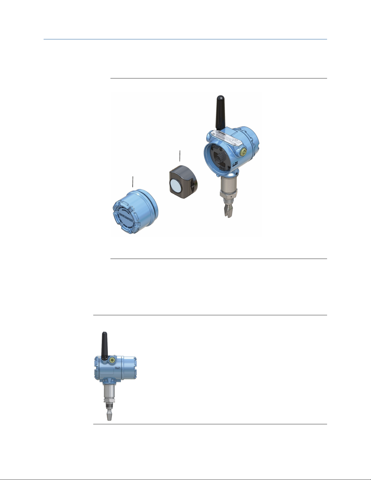
To install the battery that supplies all power to the Rosemount 2160:
Procedure
1. Remove the power module cover.
2.
Connect the power module.
28 Reference Manual
Page 29
A
B
Reference Manual Installation
00809-0100-4160 May 2022
3. Replace the power module cover and tighten to safety specification (metal-tometal).
Figure 3-14: Wireless Power Module Installation
A. Power module cover
B. Power module
3.3.7 Position the antenna
The antenna should be positioned vertically, either straight up or straight down, and it
should be approximately 3 ft. (1 m) from any large structure, building, or conductive
surface to allow for clear communication to other devices.
Figure 3-15: Antenna Positioned Vertically
Rosemount 2160 Wireless Level Detector 29
Page 30
A B C D
Installation Reference Manual
May 2022 00809-0100-4160
3.3.8 Adjust LCD meter orientation
If a device display is ordered, it will be shipped attached to the level detector. The display is
ordered in the level detector model number, option code M5.
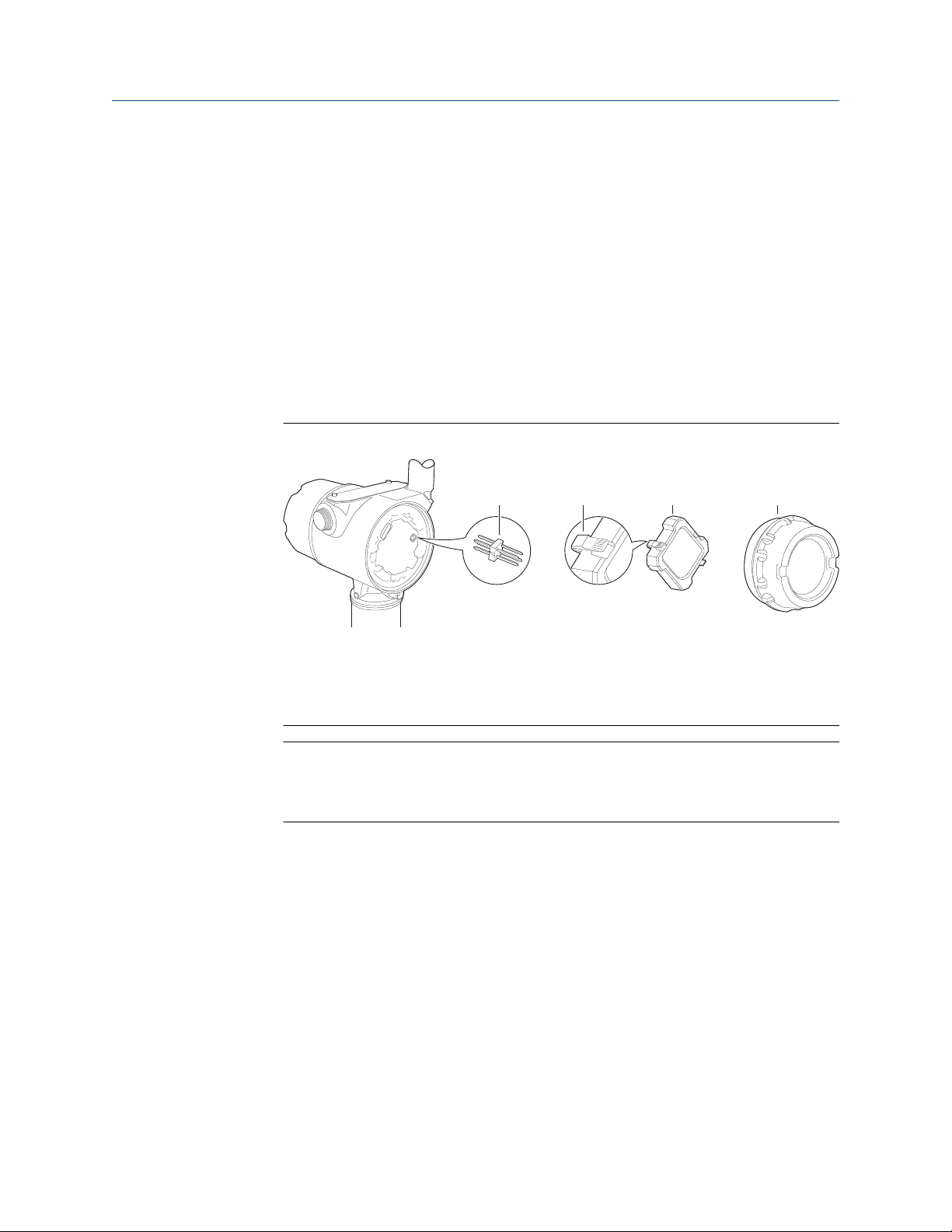
Rotate the device display
The device display can be rotated in 90-degree increments.
Procedure
1. Squeeze the two black tabs on opposite sides of the display. Refer to
2. Gently pull out the display.
3. Rotate the display to the desired orientation, and snap the display into place.
Figure 3-16: Device Display
A. Display pins
B. Black tabs
C.
Display
D. Cover
Note
If the device display four-pin connector is inadvertently removed from the interface
board, carefully reinsert the connector before snapping the device display back into
place.
Figure 3-16.
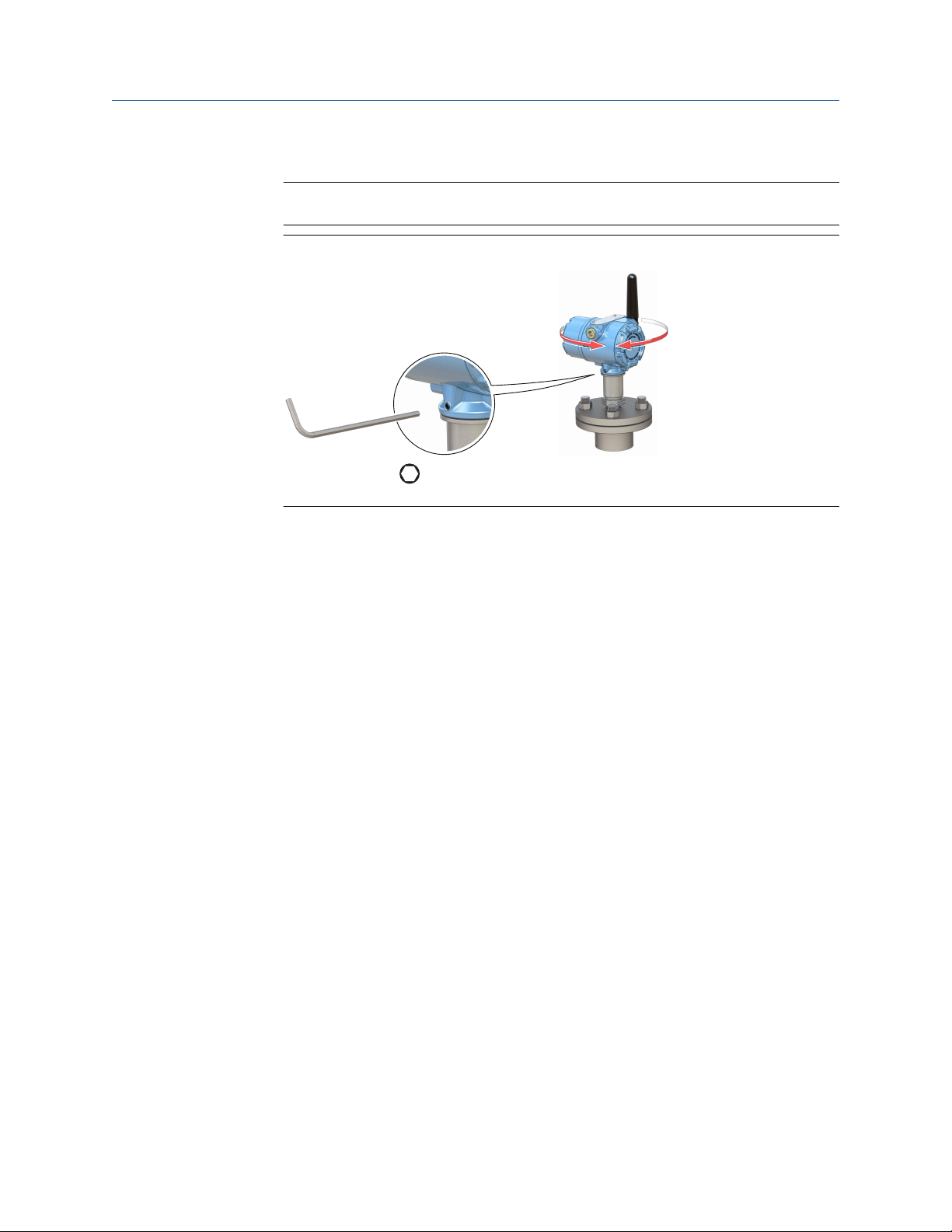
3.3.9 Adjust housing orientation
The housing can be rotated for optimal viewing of the optional LCD display and to get the
best antenna position.
Procedure
1. Loosen the set screw until the level detector housing can rotate smoothly.
Do not unscrew all the way. Rotating the housing, without this screw in place, can
damage the internal wiring.
2.
First, rotate the housing clockwise to the desired location.
If the desired location cannot be achieved due to thread limit, rotate the housing
30 Reference Manual
counterclockwise.
Page 31
H3/32 in.
Torque 30 in-lb (3 Nm)
Reference Manual Installation
00809-0100-4160 May 2022
3. Re-tighten the set screw.
Note
Do not attempt to rotate the housing beyond the thread limit.
Figure 3-17: Housing Rotation
Rosemount 2160 Wireless Level Detector 31
Page 32

Installation Reference Manual
May 2022 00809-0100-4160
32 Reference Manual
Page 33

Reference Manual Configuration
00809-0100-4160 May 2022
4 Configuration
4.1 Safety messages
Instructions and procedures in this section may require special precautions to ensure the
safety of the personnel performing the operations. Information that potentially raises
safety issues is indicated by a warning symbol ( ). Refer to the following safety messages
before performing an operation preceded by this symbol.
WARNING
Failure to follow safe installation and servicing guidelines could result in death or
serious injury.
Ensure the level detector is installed by qualified personnel and in accordance with
applicable code of practice.
Use the level detector only as specified in this manual. Failure to do so may impair the
protection provided by the level detector.
The weight of a level detector with a heavy flange and extended fork length may exceed
37 lb. (18 kg). A risk assessment is required before carrying, lifting, and installing the level
detector.
Repair, e.g. substitution of components, etc. may jeopardize safety and is under no
circumstances allowed.
WARNING
Explosions could result in death or serious injury.
Verify that the operating atmosphere of the level detector is consistent with the
appropriate hazardous locations certifications.
Before connecting a handheld communicator in an explosive atmosphere, ensure that the
instruments in the loop are installed in accordance with intrinsically safe or non-incendive
field wiring practices.
WARNING
Process leaks could result in death or serious injury.
Ensure the level detector is handled carefully. If the process seal is damaged, gas might
escape from the vessel (tank) or pipe.
Rosemount 2160 Wireless Level Detector 33
Page 34

Configuration Reference Manual
May 2022 00809-0100-4160
4.2 Configuration procedure
Follow these steps for proper configuration:
Procedure
1. Get started with your preferred configuration tool.
• AMS Wireless Configurator
• Handheld communicator
2.
Join device to wireless network.
a) Insert the power module.
b) Connect to device.
c) Configure update rate.
d) Obtain network ID and join key.
e) Enter network ID and join key.
f) Verify device joins Network.
3. Configure device.
a) Connect to device.
b) Configure using basic setup.
c) Consider optional guided setups.
4. Verify the fork status (dry or wet) is as expected.
4.3 Get started with your preferred configuration tool
4.3.1 AMS Wireless Configurator
The AMS Wireless Configurator is the recommended software tool for the wireless
network devices, and is supplied with the Emerson Wireless Gateway.
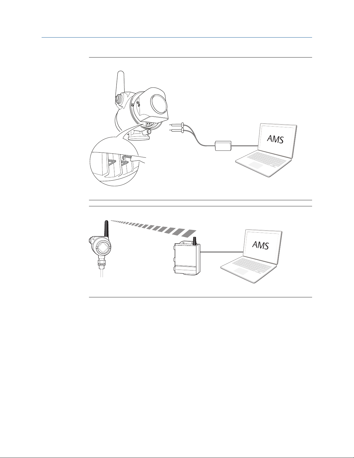
Configuration can be done by connecting to the wireless network devices either point-topoint using a HART modem as shown in Figure 4-1, or wirelessly through the Gateway as
shown in Figure 4-2. Initial configuration to join a device to the wireless network must be
done point-to-point.
34 Reference Manual
Page 35
$
$
Reference Manual Configuration
00809-0100-4160 May 2022
Figure 4-1: Connect Point-to-Point using HART Modem
A. Communication terminals
Figure 4-2: Connect Wirelessly through the Wireless Gateway
A. Wireless Gateway
Download the latest Device Descriptor (DD)
The Device Descriptor (DD) is a configuration tool that is developed to assist the user
through the configuration.
Procedure
Download the latest DD at Emerson.com/DeviceInstallKits.
Add the DD to AMS Wireless Configurator
Prerequisites
The Rosemount 2160 DD is typically installed together with AMS Wireless Configurator.
Procedure
1. Close AMS Wireless Configurator.
Rosemount 2160 Wireless Level Detector 35
Page 36

Configuration Reference Manual
May 2022 00809-0100-4160
2. Go to Start → Programs → AMS Device Manager and select Add Device Type.
3. Browse to the downloaded DD files and select
Need help?
In the Add Device Type application, select the Help button for more information on how to
complete this operation.
Ok.
Configure the HART® modem interface
Before connecting to the device using a HART modem, the HART modem interface must
be configured in AMS Wireless Configurator.
Procedure
1. Close AMS Wireless Configurator.
2.
Go to Start → Programs → AMS Device Manager and select Network
Configuration.
3. Select Add.
4. In the drop down list, select HART modem and then select Install.
5. Follow the on-screen instructions.
Need help?
In the Network Configuration application, select the Help button for more information on
how to complete this operation.
Configure the wireless network interface
Before connecting to the device wirelessly using a Wireless Gateway, the wireless network
must be configured in AMS Wireless Configurator.
Procedure
1. Close AMS Wireless Configurator.
2. Go to Start → Programs → AMS Device Manager and select Network
Configuration.
3. Select Add.
4. In the drop-down list select Wireless Network and then select Install.
5. Follow the on-screen instructions.
Need help?
In the Network Configuration application, select the Help button for more information on
how to complete this operation.
4.3.2 Handheld communicator
This section describes how to prepare the handheld communicator to communicate with
a Rosemount 2160. The handheld communicator can be used to configure the device with
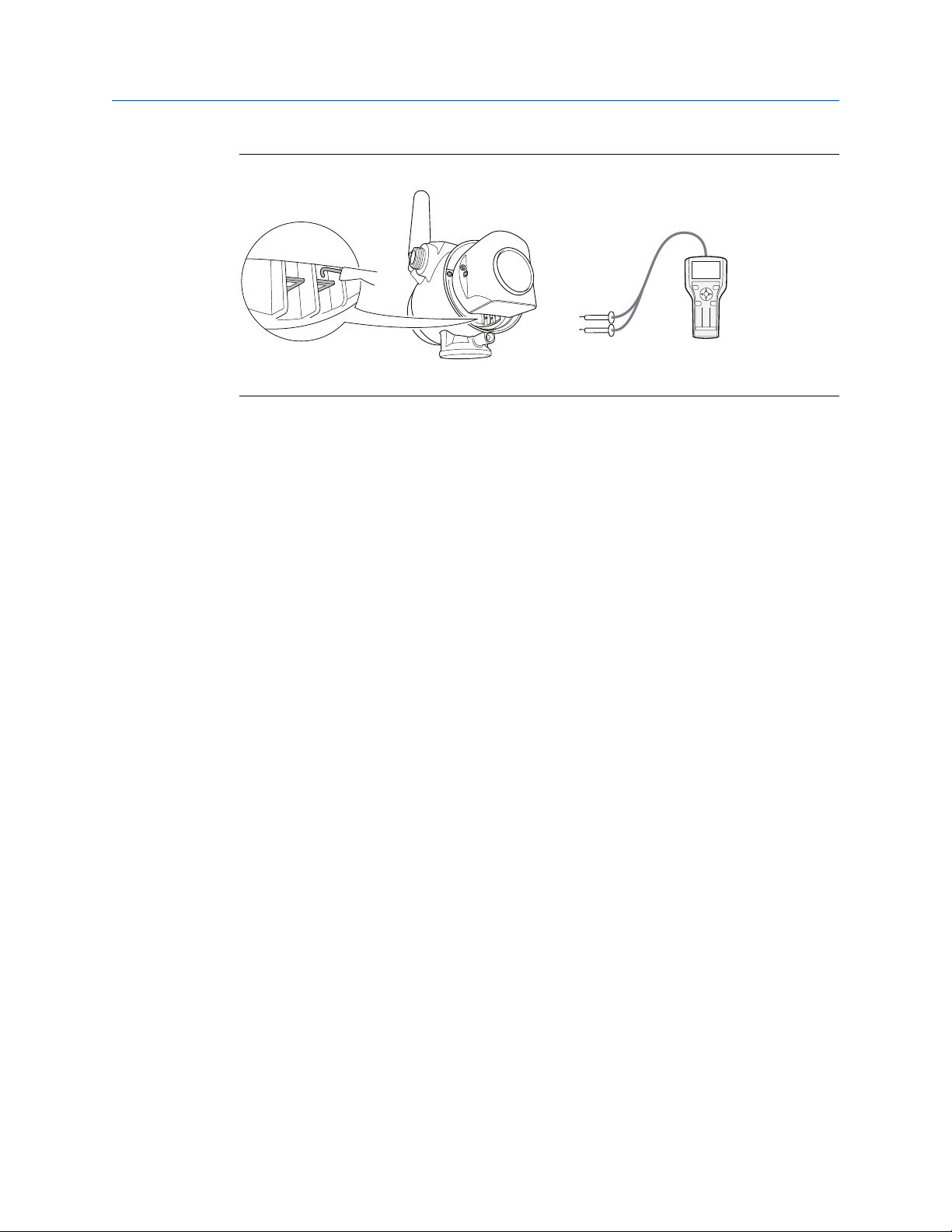
a point-to-point connection. Connect the leads on the handheld communicator to the
communication terminals of the device.
36 Reference Manual
Page 37
$
1 2 3
4 5
6
7 809
Reference Manual Configuration
00809-0100-4160 May 2022
Figure 4-3: Connect Point-to-Point using a Handheld Communicator
A. Communication terminals
Get the latest Device Descriptor (DD)
If the DD is not installed in your handheld communicator, see the appropriate handheld
communicator User’s Manual available at Emerson.com/FieldCommunicator for
instructions on how to update the handheld communicator with the latest DD.
4.4 Join device to wireless network
4.4.1 Power up the wireless device
Prerequisites
Make sure that the Wireless Gateway is installed and functioning properly before any
wireless field devices are powered.
Wireless devices should be powered up in order of proximity from the Gateway, beginning
with the closest. This will result in a simpler and faster network installation.
Procedure
1. Install the power module.
Enable Active Advertising on the Gateway to ensure that new devices join the
2.
network faster.
Related information
Install the power module
Startup screen sequence
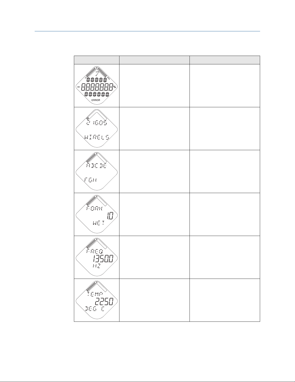
The following screens will be displayed in sequence when the power module is first
connected to the Rosemount 2160.
Rosemount 2160 Wireless Level Detector 37
Page 38
Configuration Reference Manual
May 2022 00809-0100-4160
Table 4-1: Startup Screen Sequence
Screen Sequence Description
1. All segments ON Used to visually determine if there
are any bad segments on the device
display.
2. Device identification Identification string used to
determine the device type.
3. Device information: Tag User entered tag, 8 characters long.
This screen will not display if all
characters are blank.
4. Primary Variable (PV) - Fork state Fork (switch) state.
5. Secondary Variable (PV) - Fork
frequency
6. Tertiary Variable (TV) - Electronic
temperature
Fork (switch) frequency.
Temperature value of device
electronics.
38 Reference Manual
Page 39

Reference Manual Configuration
00809-0100-4160 May 2022
Table 4-1: Startup Screen Sequence (continued)
Screen Sequence Description
7. Quaternary Variable (QV) - Supply
voltage
8. Active alert present This screen will only appear if there
Voltage reading of the power
module.
is at least one active alert present.
For detailed information of the
failure source and recommended
actions, go to the Active Alerts
screen in AMS Wireless Configurator
or the handheld communicator.
Some active alerts will be displayed
on the LCD display as part of the
diagnostic button screen sequence.
Rosemount 2160 Wireless Level Detector 39
Page 40
$
&
%
1 2 3
4 5 6
7 809
Configuration Reference Manual
May 2022 00809-0100-4160
4.4.2 Connect to device
Procedure
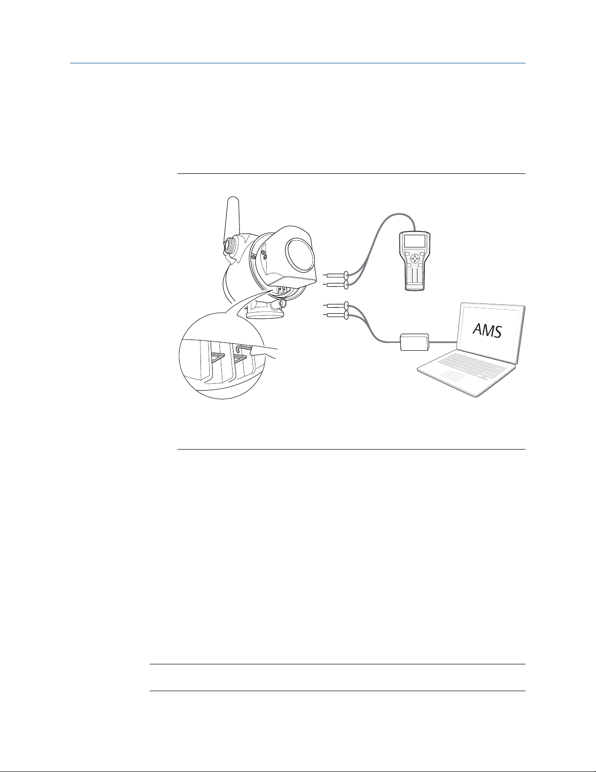
1. Connect a handheld communicator or a HART® modem to the communication
terminals as shown in
Figure 4-4: Connect to Device
Figure 4-4.
A. Communication terminals
B. Handheld communicator
C.
HART modem
2. Do one of the following:
• AMS Wireless Configurator:
a. Start AMS Wireless Configurator.
b.
Select View → Device Connection View.
c. Double click the device under the HART modem.
• Handheld communicator:
— Turn on the handheld communicator and connect to the device.
4.4.3 Configure update rate
The update rate is the frequency at which a new measurement is transmitted over the
wireless network. The default update rate is 1 minute.
Prerequisites
Note
If the time between each update is too long, the high/low alerts may be triggered too late.
40 Reference Manual
Page 41
Reference Manual Configuration
00809-0100-4160 May 2022
Procedure
1. Select
2. Select Configure Update Rate and follow the on-screen instructions.
Related information
Wireless update rate
Configure → Guided Setup.
Note
If the update rate is reconfigured, the unit will continuously update for five minutes
and then update with the reconfigured update rate.
4.4.4 Obtain network ID and join key
In order to communicate with the Wireless Gateway, and ultimately the host system, the
Rosemount 2160 must be configured to communicate on the wireless network. This step
is the wireless equivalent of connecting wires from a device to the host system.
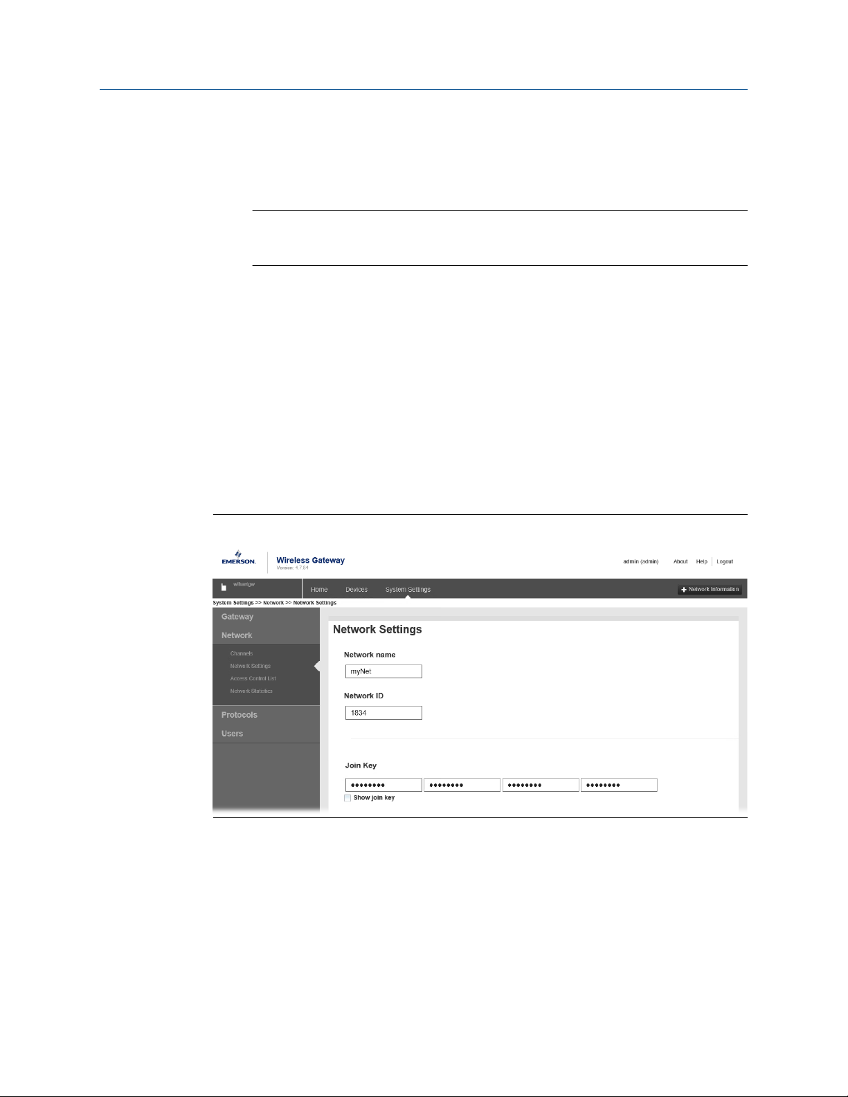
Procedure
From the Wireless Gateway's integrated web interface, select System Settings →
Network → Network Settings.
Figure 4-5: Gateway Network Settings
4.4.5 Enter network ID and join key
The device must be configured with the same Network ID and Join Key as the Gateway in
order to join the network.
Procedure
1. Select
2. Select Join Device to Network and follow on-screen the instructions.
Rosemount 2160 Wireless Level Detector 41
Configure → Guided Setup.
Page 42
Configuration Reference Manual
May 2022 00809-0100-4160
Postrequisites
If the device is not to be commissioned yet, remove the power module and fasten the
housing cover. This is to conserve power module life and to ensure safe transportation.
The power module should be inserted only when the device is ready to be commissioned.
4.4.6 Verify device joins network
Network connection can be verified in four ways, further described in this section:
• At the device display
• Using the AMS Wireless Configurator
• In the Wireless Gateway's integrated web interface
• Using the handheld communicator
If the Rosemount 2160 was configured with the Network ID and Join Key, and sufficient
time has passed, the device should be connected to the network. It usually takes a few
minutes for the device to join the network.
Verify by device display
Procedure
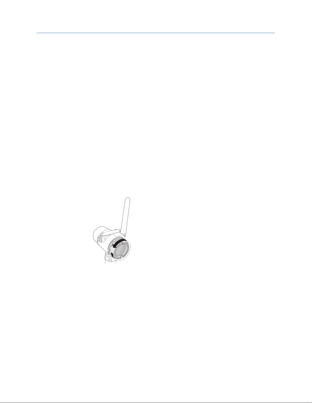
1. Unscrew the device display cover.
42 Reference Manual
Page 43
n e t w k
u n k n w n
n e t w k
j o i n g
n e t w k
a - s r c h
Reference Manual Configuration
00809-0100-4160 May 2022
2. Press the DIAG button.
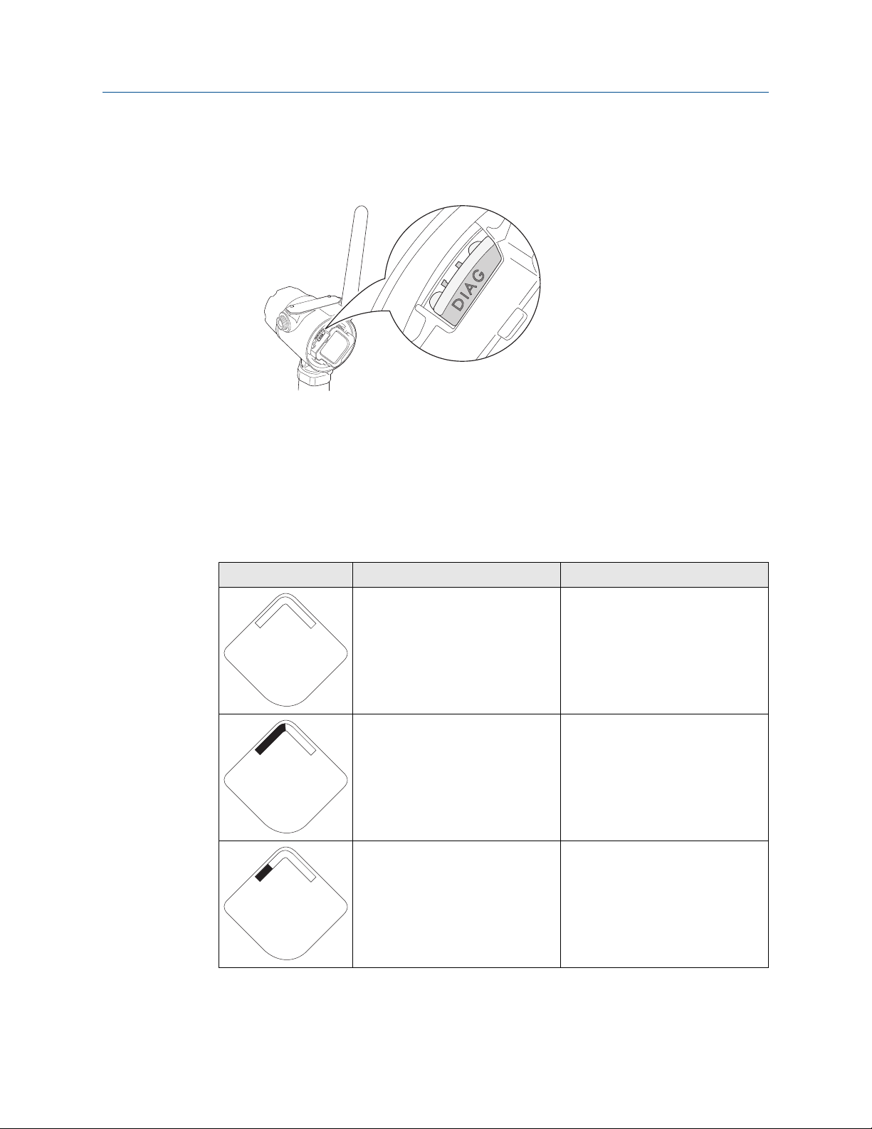
The display will show: Tag, Device Serial Number, Network ID, Network Connection
Status, and Supply Voltage screens.
When the network diagnostic status is displayed as “NETWK OK”, the device has
successfully joined the network.
Network connection status screens
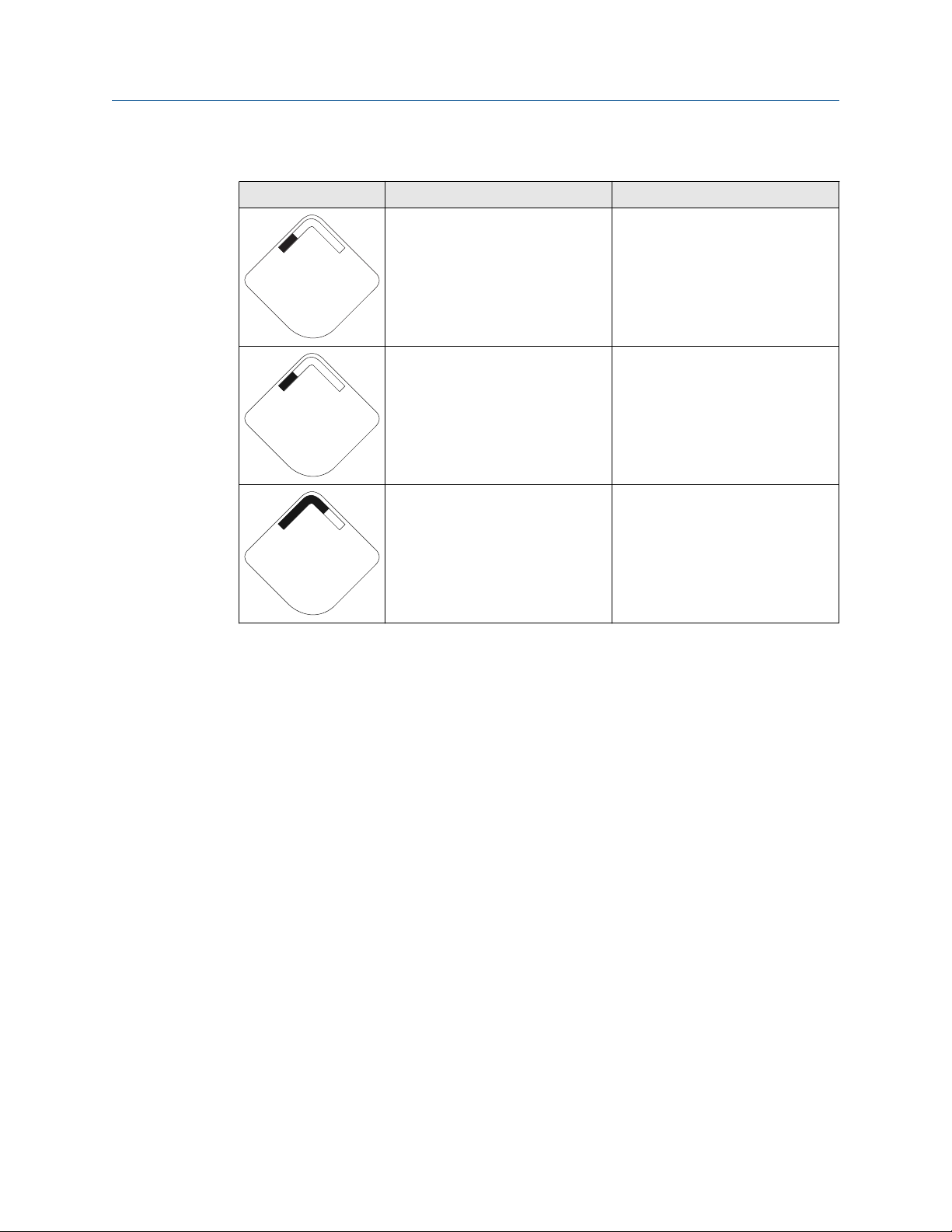
When joining the wireless network, there is a sequence of status changes until the
network is finally joined. Table 4-2 presents the different network connection status
screens.
Table 4-2: Network Connection Status Screens
Screen Status Description
Network Unknown The device is still in the process of
being activated.
Network Joining The device has started the process
of joining a network.
Network Active Search The device is actively searching for a
network.
Rosemount 2160 Wireless Level Detector 43
Page 44
n e t w k
p - s r c h
n e t w k
s l e e p
n e t w k
1 p a r n t
Configuration Reference Manual
May 2022 00809-0100-4160
Table 4-2: Network Connection Status Screens (continued)
Screen Status Description
Network Passive Search The device is passively searching for
a network.
Network Sleep The device couldn’t find the
network and is in deep sleep mode
to preserve battery power.
Network 1 Parent The device has joined a network and
has been fully configured but has
only 1 parent device.
Verify with AMS Wireless Configurator
Procedure
1. Start the AMS Wireless Configurator.
Navigate to the Smart Wireless Gateway icon.
2.
When the device has joined the network, it will appear in the AMS Wireless
Configurator window.
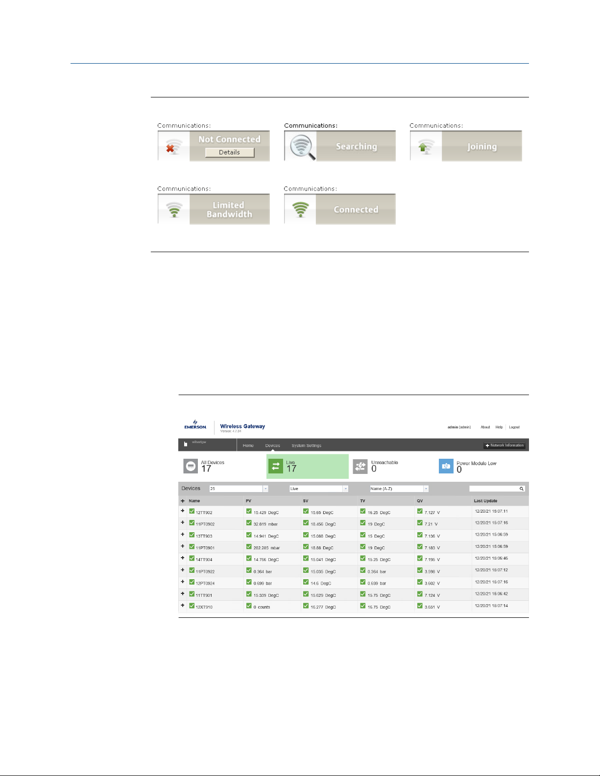
Network connection status
Figure 4-6 presents the different network connection status images that are shown in the
AMS Wireless Configurator Overview screen.
44 Reference Manual
Page 45
Reference Manual Configuration
00809-0100-4160 May 2022
Figure 4-6: Network Connection Status Images
Verify by Gateway
Procedure
1. From the Emerson Wireless Gateway home page, navigate to the Devices page.
This page shows whether the device has joined the network and if it is
communicating properly.
2. Locate the device in question and verify all status indicators are good (green).
It may take several minutes for the device to join the network and be seen on the
Gateway's integrated web interface.
Figure 4-7: Wireless Gateway Devices Page
Verify with handheld communicator
Prerequisites
Do not remove the power module. Removing the power module may cause the device to
drop off the network.
Rosemount 2160 Wireless Level Detector 45
Page 46

Configuration Reference Manual
May 2022 00809-0100-4160
Note
In order to communicate with a handheld communicator, the device must be powered by
the power module.
Procedure
1. Connect the handheld communicator.
2.
Select Service Tools → Communications.
3. Select Join Status.
4.5 Configure device using guided setup
The options available in the Basic Setup wizard include all items required for basic
operation.
Procedure
Select
1.
2. Select Basic Setup and follow the on-screen instructions.
3. Consider optional guided setups such as Configure Device Display and Configure
Configure → Guided Setup.
Alerts.
46 Reference Manual
Page 47
S u p l y
7. 2 1
v o l t s
Reference Manual Operation
00809-0100-4160 May 2022
5 Operation
5.1 Device display screen messages
The device display can be used to present different variables and a diagnostic screen
sequence.
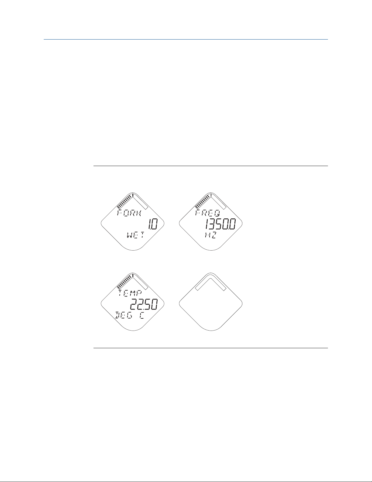
5.1.1 Variable screens
The Rosemount 2160 can display the following variables:
Figure 5-1: LCD Display Variables
PV - Fork state SV - Fork frequency
TV - Electronic temperature QV - Supply voltage
Rosemount 2160 Wireless Level Detector 47
Page 48
Operation Reference Manual
May 2022 00809-0100-4160
5.2 View diagnostic screens
The diagnostic button screen sequence on the device display can be used to obtain
detailed diagnostic information.
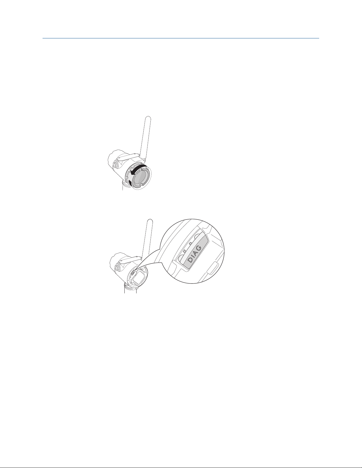
Procedure
1. Unscrew the device display cover.
2. Press and hold the DIAG button until the first diagnostic button screen appears on
the device display. Release the DIAG button.
The device display will now automatically show the diagnostic screens.
5.2.1 Diagnostic button screen sequence
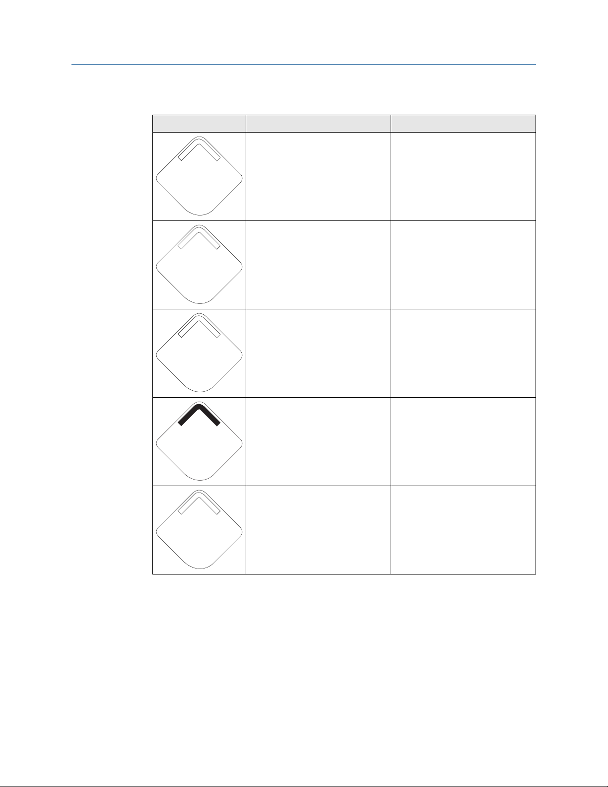
The following five screens will display when the device is operating properly and the DIAG
button has been pressed.
48 Reference Manual
Page 49
A b c d e
f g h
i d - X X
X X X X X X
n e t w k
13 0 5
I D
n e t w k
O K
S u p l y
7. 2 1
v o l t s
Reference Manual Operation
00809-0100-4160 May 2022
Table 5-1: Diagnostic Button Screen Sequence
Screen Sequence Description
1. Device Information: Tag User entered tag which is 8
characters long. This screen will not
display if all characters are blank.
2. Device Serial Number Used to determine Device Serial
Number.
3. Network ID Used to determine the entered
Network ID in the device.
Related information
Device display alerts
4. Network Connection Status The screen displayed is dependent
on the progress of the device in
joining the wireless network.
5. Supply voltage Used to indicate the voltage of the
battery.
Rosemount 2160 Wireless Level Detector 49
Page 50

Operation Reference Manual
May 2022 00809-0100-4160
5.3 View measurement data
Current measurement data of the primary variables are presented on the Overview screen.
To view all current measurement values:
Procedure
Select Service Tools → Variables.
5.3.1 Interpret measurement status
A “Good” or “Bad” status next to a value is an indication of the reliability or integrity of the
data being received, not an indication of whether or not the value is within the configured
upper or lower ranges. A value that triggers an alert, such as a high or low temperature
indication, will change the overall status of the device, but the measurement might still be
indicated as “Good” if the reliability of the data is good.
5.4 Check device status
The overall device status is presented under the Overview screen. The device reports
diagnostic alerts when there is a device malfunction.
Procedure
1. Go to the
2. If status is anything other than Good, select the button in the device status image to
open a window with Active Alerts.
Active Alerts can also be obtained via Service Tools → Alerts.
Overview screen to view the overall device status.
50 Reference Manual
Page 51
Reference Manual Operation
00809-0100-4160 May 2022
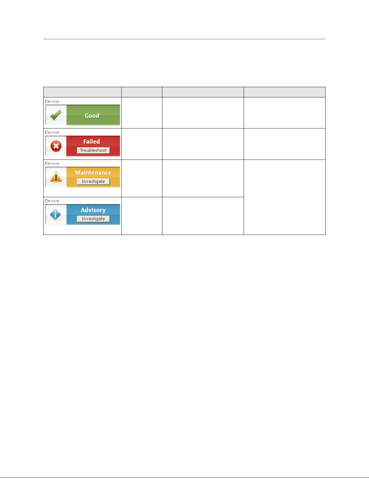
5.4.1 Device status images
Table 5-2: Presentation of Device Status Images
Device status image Category Condition Action
Good No active alert. N/A
Failed At least one Failure Alert is active. Click the Troubleshoot button to
open a window with Active Alerts
together with recommended
actions.
Maintenance At least one Maintenance Alert is
active (and no Failed alerts).
Advisory At least one Advisory Alert is
active (and no Failed or
Maintenance Alerts).
Click the Investigate button to
open a window with Active Alerts
together with recommended
actions.
Rosemount 2160 Wireless Level Detector 51
Page 52

Operation Reference Manual
May 2022 00809-0100-4160
52 Reference Manual
Page 53

Reference Manual Service and troubleshooting
00809-0100-4160 May 2022
6 Service and troubleshooting
6.1 Safety messages
Instructions and procedures in this section may require special precautions to ensure the
safety of the personnel performing the operations. Information that potentially raises
safety issues is indicated by a warning symbol ( ). Refer to the following safety messages
before performing an operation preceded by this symbol.
WARNING
Failure to follow safe installation and servicing guidelines could result in death or
serious injury.
Ensure the level detector is installed by qualified personnel and in accordance with
applicable code of practice.
Use the level detector only as specified in this manual. Failure to do so may impair the
protection provided by the level detector.
The weight of a level detector with a heavy flange and extended fork length may exceed
37 lb. (18 kg). A risk assessment is required before carrying, lifting, and installing the level
detector.
Repair, e.g. substitution of components, etc. may jeopardize safety and is under no
circumstances allowed.
WARNING
Explosions could result in death or serious injury.
Verify that the operating atmosphere of the level detector is consistent with the
appropriate hazardous locations certifications.
Before connecting a handheld communicator in an explosive atmosphere, ensure that the
instruments in the loop are installed in accordance with intrinsically safe or non-incendive
field wiring practices.
WARNING
Process leaks could result in death or serious injury.
Ensure the level detector is handled carefully. If the process seal is damaged, gas might
escape from the vessel (tank) or pipe.
6.2 Device display alerts
The following active alert screens will show the device diagnostics depending on the state
of the device.
Rosemount 2160 Wireless Level Detector 53
Page 54

Service and troubleshooting Reference Manual
May 2022 00809-0100-4160
If the device display shows ALERT PRESNT but none of the following screens appear, then
go to the Active Alerts screen in AMS Wireless Configurator or the handheld
communicator for further information.
For detailed information of the failure source and recommended actions, go to the Active
Alerts screen in AMS Wireless Configurator or the handheld communicator.
6.2.1 Device failure
Screen
Cause
There is a critical error which may prevent the device from operating correctly.
Recommended actions
Check additional status screens for more information.
6.2.2 Supply voltage failure
Screen
Cause
The terminal voltage has dropped below level of operating limit.
Recommended actions
Replace the power module.
Related information
Replace power module
54 Reference Manual
Page 55

Reference Manual Service and troubleshooting
00809-0100-4160 May 2022
6.2.3 Supply voltage low
Screen
Cause
The supply voltage is low and may soon affect broadcast updates.
Recommended actions
Replace the power module.
Related information
Replace power module
6.2.4 Radio failure
Screen
Cause
The wireless radio has detected a failure or stopped communicating.
Recommended actions
Reset the device.
1.
2.
If the condition persists, contact your local Emerson representative.
Related information
Perform a device reset
Rosemount 2160 Wireless Level Detector 55
Page 56

Service and troubleshooting Reference Manual
May 2022 00809-0100-4160
6.2.5 Configuration failure
Screen
Cause
Configuration of the device is invalid such that critical operation of the device may be
affected.
Recommended actions
Check the extended configuration status to identify which configuration item(s) need
to be corrected.
6.2.6 Configuration warning
Screen
Cause
Configuration of the device is invalid such that non-critical operation of the device may be
affected.
Recommended actions
Check the extended configuration status to identify which configuration item(s) need
to be corrected.
56 Reference Manual
Page 57

Reference Manual Service and troubleshooting
00809-0100-4160 May 2022
6.2.7 Sensor failure
Screen
Cause
A sensor attached to the device has failed, and valid readings from that sensor are no
longer possible.
Recommended actions
1. Check the sensor and sensor wiring connections.
2.
Check additional status for more detailed information of the failure source.
6.3 Troubleshooting
6.3.1 LCD is not functioning
Recommended actions
1. Re-seat the LCD.
2. Verify that the LCD is a wireless LCD. An LCD from a wired device will not
function in a wireless device.
3. Verify that the LCD display mode is not disabled.
Related information
Rotate the device display
Display mode
6.3.2 Does not switch output state
Possible cause
There is no power.
Recommended actions
Check the power module is installed correctly. Try another power module.
Possible cause
Fork is damaged.
Rosemount 2160 Wireless Level Detector 57
Page 58

Service and troubleshooting Reference Manual
May 2022 00809-0100-4160
Recommended actions
Replace the device.
Possible cause
Thick encrustation on the forks.
Recommended actions
Clean the fork with care.
6.3.3 Incorrect switching of output state
Recommended actions
Check the configuration of frequency bands.
Related information
Calibration frequencies and switch points
6.3.4 Faulty switching
Symptom or indication
Turbulence.
Recommended actions
Set a longer switching time delay.
Symptom or indication
Excessive electrical noise.
Recommended actions
Suppress the cause of the interference.
Related information
Sensor output delay
6.3.5 Wireless network troubleshooting
The device is not joining the wireless network
Recommended actions
1. Verify Network ID and Join Key. The Network ID and Join Key in the device must
match the Network ID and Join Key of the Gateway.
2.
Enable High Speed Operation on the Wireless Gateway.
3. Check Power Module.
4. Verify that Active Advertising has been enabled on the Wireless Gateway.
58 Reference Manual
Page 59

Reference Manual Service and troubleshooting
00809-0100-4160 May 2022
5. Verify device is within range of at least one other wireless device or the Wireless
Gateway.
6. Verify device is configured to join. Send the “Join Now” command to the device.
Limited bandwidth error
Recommended actions
1.
Reduce the Update Rate on device.
2. Increase communication paths by adding more wireless points.
3. Check that device has been online for at least an hour.
4. Check that device is not routing through a “limited” routing node.
5. Create a new network with an additional Wireless Gateway.
6.4 Service and troubleshooting tools
This section briefly describes tools and functions in the AMS Wireless Configurator and
handheld communicator, which may be useful for servicing and troubleshooting of the
Rosemount 2160.
6.4.1 Reviewing network join status and details
View network join status
Wireless devices join the network through a four step process:
• Step 1. Network Found
• Step 2. Network Security Clearance Granted
• Step 3. Network Bandwidth Allocated
• Step 4. Network Join Complete
To view the Network Join Status of the device:
Procedure
Select Service Tools → Communications → Join Status.
Obtain network join details
Obtain detailed information about the network join, and configure how the device
attempts to join the network.
Procedure
Select Service Tools → Communications.
Rosemount 2160 Wireless Level Detector 59
Page 60

Service and troubleshooting Reference Manual
May 2022 00809-0100-4160
Network join details
Table 6-1: Network Join Details Functions
Term Description
Join Mode This mode configures how the device attempts to join the
network. Settable options are:
• Don't Attempt to Join
• Join Now
• Join on Powerup or Reset
Number of Available Neighbors Defines how many wireless devices are within the
communication range of this device. In a self-organizing
network, the more neighbors a device has, the more robust the
network will be.
Number of Advertisements
Heard
Number of Join Attempts Number of times the device has tried to join the network prior to
Number of advertised packets received by the device from all
networks within range.
being accepted. Too many join attempts result in the device
considering the join attempt as failed. If this happens, re-check
the Join Key and Network ID.
6.4.2 View diagnostic information
Procedure
Select Service Tools → Maintenance → Diagnostics.
Sensor frequency
The vibrating fork frequency is indicated in the read-only Sensor Frequency device
variable.
Temperature compensation
The temperature coefficient of the vibrating fork sensor in units of %/°C.
Uncompensated frequency
Uncompensated Frequency indicates the vibrating fork frequency before compensating
for a varying process temperature.
Sensor state
This is a read-only variable and indicates the present state of the vibrating fork sensor.
As the vibrating fork sensor becomes immersed in a process liquid, the vibration frequency
decreases and the sensor state changes to a ‘wet state’ at the detection point.
When a process liquid falls away from the fork, the vibration frequency increases and the
sensor state changes to a ‘dry state’ at a detection point.
60 Reference Manual
Page 61

Reference Manual Service and troubleshooting
00809-0100-4160 May 2022
Sensor status
This is a read-only variable. It indicates if the level detector is operating in a valid or fault
state.
The Sensor Status is dependent on the configuration of Sensor State and Operation Mode.
Sensor status logic
Table 6-2: Normal Mode
Sensor status Sensor state
Valid Dry 0.0 (Dry)
Valid Wet 1.0 (Wet)
(1) Sensor Fault Delay does not delay the update of Sensor State when the operation mode is
Normal.
Note
If the operation mode is Normal, Sensor State cannot indicate Too Dry, Too Wet, or Zero,
and the Sensor Status always indicates a Valid state.
(1)
PV (output status)
Table 6-3: Enhanced Mode, Fault = Wet
Sensor status Sensor state
Valid Dry 0.0 (Dry)
Fault Too Dry (Fault) 1.0 (Wet)
Valid Wet 1.0 (Wet)
Fault Too Wet (Fault) 1.0 (Wet)
Fault Zero 1.0 (Wet)
(1) Sensor Fault Delay delays the update of Sensor State when the operation mode is Enhanced.
(2) PV is not changed.
(3) PV is automatically changed to 1.0 (Wet process condition).
(1)
PV (output status)
(2)
(3)
(2)
(3)
(3)
Table 6-4: Enhanced Mode, Fault = Dry
Sensor status Sensor state
Valid Dry 0.0 (Dry)
Fault Too Dry (Fault) 0.0 (Dry)
Valid Wet 1.0 (Wet)
Fault Too Wet (Fault) 0.0 (Dry)
Fault Zero 0.0 (Dry)
(1)
PV (output status)
(2)
(3)
(2)
(3)
(3)
(1) Sensor Fault Delay delays the update of Sensor State when the operation mode is Enhanced.
(2) PV is not changed.
(3) PV is automatically changed to 0.0 (Dry process condition).
Rosemount 2160 Wireless Level Detector 61
Page 62

Service and troubleshooting Reference Manual
May 2022 00809-0100-4160
Calibration frequencies and switch points
The switching points for Sensor State transitions are determined from these read-only
frequencies:
Table 6-5: Calibration Frequencies and Switch Points
Term Description
Dry fork frequency This is the frequency recorded when the Rosemount 2160 was
calibrated in dry conditions. Typically it is in the range 1.2 to 1.5
KHz.
Dry to too dry Above this upper limit, a measured frequency is considered to be
a fault by being outside of the normal dry fork range.
The level detector must be operating in Enhanced Mode if this
fault is to be indicated in the Sensor Status variable.
Dry to indeterminate Above this upper limit, a measured frequency is not yet
considered to be a fault but is close to being outside of the
normal dry fork range.
Wet to indeterminate Below this lower limit, a measured frequency is not yet
considered to be a fault but is close to being outside of the
normal wet fork range.
Wet to too wet Below this lower limit, a measured frequency is considered to be
a fault by being outside of the normal wet fork range.
The level detector must be operating in Enhanced Mode if this
fault is to be indicated in the Sensor Status variable.
Zero Below this low limit, a measured frequency is considered to be 0
Hz and a fault.
The level detector must be operating in Enhanced Mode if this
fault is to be indicated in the Sensor Status variable.
Note
When the level detector is operating in Normal Mode, a 0 Hz
sensor frequency represents a Wet condition (and not a fault).
When operating in Enhanced Mode, a 0 Hz sensor frequency
represents a fault condition.
6.4.3 View counters/timers
Procedure
Select Service Tools → Maintenance → Counters/Timers.
62 Reference Manual
Page 63

Reference Manual Service and troubleshooting
00809-0100-4160 May 2022
Counters
The Counters menu displays the following live counters:
Table 6-6: Counters Menu
Term Description
Sensor Wet Count This counter increments each time the PV (Output State)
changes "dry" and "wet" state. Optionally, reset or preset it by
setting a new value using the Reset/Preset Wet Count
command.
Calibration Count The Rosemount 2160 is calibrated under reference conditions at
the factory. In special circumstances, it may be re-calibrated in
the field and this will increment the calibration count.
Fault Count This counter increments each time there is a fault condition.
Optionally, reset the counter to zero using the Reset Fault Count
command.
Timers
The Timers menu displays the following live timers:
Table 6-7: Timers Menu
Term Description
Time Since Output Change This is the time elapsed since the PV (Output State) variable last
changed to a "dry" or "wet" state. Optionally, this timer can be
reset to zero by editing the counter.
Total Time Dry The total time that the PV (Output State) variable has been in a
'dry' state. Optionally, this timer can be reset to zero by editing
the counter.
Total Time Wet The total time that the PV (Output State) variable has been in a
'wet' state. Optionally, this timer can be reset to zero by editing
the counter.
Number of Join Attempts Number of times the device has tried to join the network prior to
being accepted. Too many join attempts result in the device
considering the join attempt as failed. If this happens, re-check
the Join Key and Network ID.
Note
Units for the timers are days, hours, minutes, and seconds. Seconds are not shown for long
times.
6.4.4 Dry fork calibration
This command starts the on-site calibration of the fork sensor in dry process conditions. It
should only be performed by authorized persons.
A comparison is made between the live fork sensor frequency measured in dry process
conditions and original factory-set Dry Fork Frequency value.
Rosemount 2160 Wireless Level Detector 63
Page 64

Service and troubleshooting Reference Manual
May 2022 00809-0100-4160
If the difference is greater than Allowable Change In Dry Fork Frequency, the re-calibration
is rejected. Check the fork for damage, corrosion, or coating, and clean it if necessary
before re-trying.
When the calibration is successful, Dry Fork Frequency is set to the new dry frequency.
Related information
Allowable change in fork frequency
Start the dry fork calibration
Procedure
1. Select
2. Select Calibrate Dry Fork and follow the on-screen instructions to perform the dry
Service Tools → Maintenance → Calibrate.
fork calibration.
Sensor calibration status
Sensor Calibration Status indicates:
Status Description
Factory calibrated No further calibration is normally required.
Site calibrated Calibration successfully performed on-site.
Un-calibrated Calibration is required. Contact the factory.
Restoring factory calibration of dry fork sensor
This command restores the factory calibration of the fork sensor in dry process conditions.
It is accessible after a site calibration has been performed, but should only be performed
by authorized persons.
Restoring site calibration of dry fork sensor
This command restores the site calibration of the fork sensor in dry process conditions. It is
accessible after the restoration of a factory calibration has been performed, but should
only be performed by authorized persons.
6.4.5 Adjust sensor compensation
The frequency of the vibrating fork sensor may be affected by a process temperature
being different to the calibrated temperature. Entering a known process temperature can
compensate accordingly and provide an improved frequency switching point.
Procedure
1. Select
2. Under Sensor Compensation, enter the known Process Temperature.
64 Reference Manual
Service Tools → Maintenance → Calibrate.
Page 65

Reference Manual Service and troubleshooting
00809-0100-4160 May 2022
6.4.6 Locate the device
Use the Locate Device function to identify this device by showing a pattern on the device
display, as illustrated in Figure 6-1.
Procedure
1. Select
2. Select Locate Device and follow the on-screen instructions.
Service Tools → Maintenance → Routine Maintenance.
Figure 6-1: Locate Device Pattern
6.4.7 Run the install new power module setup
Run this setup when a new power module is installed.
Procedure
1. Select
2. Select Install New Power Module and follow the on-screen instructions.
Service Tools → Maintenance → Routine Maintenance.
6.4.8 Perform a device reset
The Device Reset function re-starts electronics of the Rosemount 2160 without having to
cycle the power. It preserves the user-configuration.
Procedure
Select
1.
2. Select Device Reset and follow the on-screen instructions.
Service Tools → Maintenance, → Reset/Restore
6.4.9 Load user defaults
The Load User Defaults function resets the user-configuration to the ex-factory settings.
Procedure
Select
1.
2. Select Load User Defaults and follow the on-screen instructions.
Rosemount 2160 Wireless Level Detector 65
Service Tools → Maintenance → Reset/Restore.
Page 66
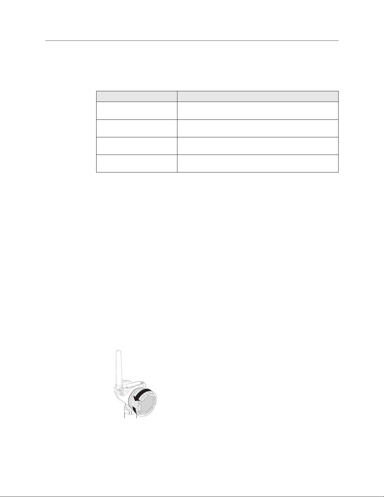
Service and troubleshooting Reference Manual
May 2022 00809-0100-4160
6.4.10 Device variable simulation
Simulation mode is available for the following device variables:
Variable Description
Output State This device variable can be temporarily overridden to be ‘wet’
(1.0) or ‘dry’(0.0).
Sensor Frequency This device variable can be temporarily overridden with an
entered frequency in the range 0 to 3000 Hz.
Electronics Temperature This device variable can be temporarily overridden with an
entered temperature value.
Voltage Supply This device variable can be temporarily overridden with an
entered voltage value.
Simulate a device variable
Procedure
1. Select
2. Select a device variable to be used for the simulation.
3. Follow on-screen instructions to perform the simulation.
Postrequisites
A simulation is canceled by exiting the screen. It can also be cleared by the power cycling
or using the Device Reset command.
Service Tools → Simulate.
6.5 Replace power module
Prerequisites
Only use an Emerson approved power module designed for use with the Rosemount 2160.
The power modules are only compatible with their respective covers.
Procedure
Remove the cover.
1.
66 Reference Manual
Page 67
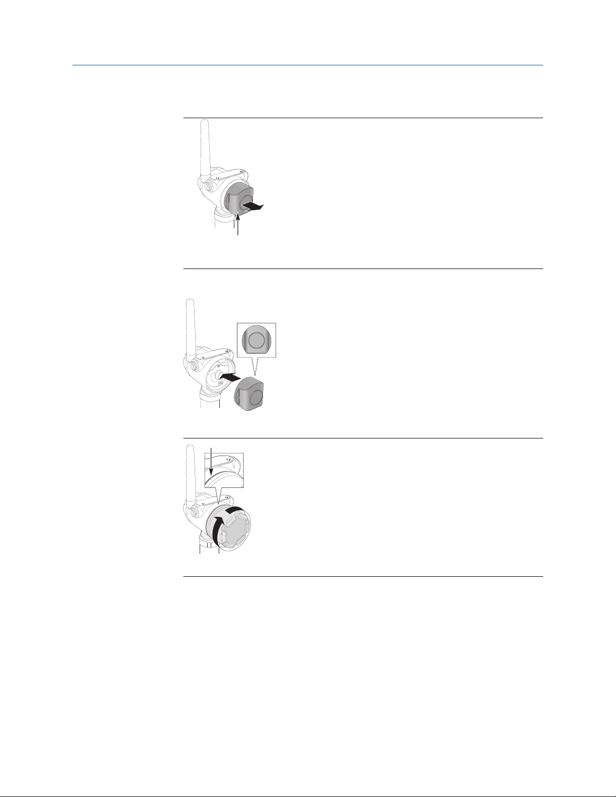
A
A
Reference Manual Service and troubleshooting
00809-0100-4160 May 2022
2. Remove the old power module.
A. Dispose of in accordance with Government regulations
3. Connect the new power module.
4. Attach and tighten the cover.
A. Keep cover tight
Postrequisites
Run the install new power module setup.
Related information
Emerson Wireless Black SmartPower Solutions Product Data Sheet
Emerson Wireless Blue SmartPower Solutions Product Data Sheet
Run the install new power module setup
Rosemount 2160 Wireless Level Detector 67
Page 68

Service and troubleshooting Reference Manual
May 2022 00809-0100-4160
6.5.1 Handling considerations
The power modules with the wireless unit contains primary lithium/thionyl chloride
batteries. Under normal conditions, the battery materials are self-contained and are not
reactive as long as the batteries and the battery pack integrity are maintained. Care should
be taken to prevent thermal, electrical or mechanical damage. Contacts should be
protected to prevent premature discharge.
Use caution when handling the power module. It may be damaged if dropped from
heights in excess of 20 ft. (6 m).
Battery hazards remain when cells are discharged.
6.5.2 Environmental considerations
As with any battery, local environmental rules and regulations should be consulted for
proper management of spent batteries. If no specific requirements exist, recycling
through a qualified recycler is encouraged. Consult the Safety Data Sheet (SDS) for battery
specific information.
6.5.3 Shipping considerations
The unit was shipped to you without the power module installed. Please remove the
power module prior to shipping.
Each Black Power Module (model number 701PBKKF) contains two “C” size primary
lithium batteries. Primary lithium batteries (charged or discharged) are regulated in
transportation by the U. S. Department of Transportation, and are also covered by IATA
(International Air Transport Association), ICAO (International Civil Aviation Organization),
and ARD (European Ground Transportation of Dangerous Goods). It is the responsibility of
the shipper to ensure compliance with these or any other local requirements. Consult
current regulations and requirements before shipping.
Each Blue Power Module (A0701PBU) contains two "D" size primary lithium batteries.
Primary lithium batteries (charged or discharged) are regulated in transportation by the
U.S. Department of Transportation, and are also covered by IATA (International Air
Transport Association), ICAO (International Civil Aviation Organization), and ARD
(European Ground Transportation of Dangerous Goods). It is the responsibility of the
shipper to ensure compliance with these or any other local requirements. Please consult
current regulations and requirements before shipping.
6.6 Opening the lid (cover)
Before opening the lid for maintenance reasons observe following items:
• Do not remove the lid while circuits are live.
• No dust deposits or whirlings are present.
• No rain can enter into the housing.
68 Reference Manual
Page 69

Reference Manual Service and troubleshooting
00809-0100-4160 May 2022
6.7 Service support
To expedite the return process, refer to Emerson.com and contact the nearest Emerson
representative.
CAUTION
Individuals who handle products exposed to a hazardous substance can avoid injury if they
are informed of and understand the hazard. Returned products must include a copy of the
required Safety Data Sheet (SDS) for each substance.
Emerson representatives will explain the additional information and procedures necessary
to return goods exposed to hazardous substances.
Rosemount 2160 Wireless Level Detector 69
Page 70

Service and troubleshooting Reference Manual
May 2022 00809-0100-4160
70 Reference Manual
Page 71

Reference Manual Specifications and reference data
00809-0100-4160 May 2022
A Specifications and reference data
A.1 General
A.1.1 Measuring technology
Vibrating fork
A.1.2 Applications
Point level detection in liquid process mediums, including coating liquids, aerated liquids,
and slurries. Suitable for horizontal and vertical installation.
A.2 Physical specifications
A.2.1 Material selection
Emerson provides a variety of Rosemount products with various product options and
configurations, including materials of construction that can be expected to perform well in
a wide range of applications. The Rosemount product information presented is intended
as a guide for the purchaser to make an appropriate selection for the application. It is the
purchaser’s sole responsibility to make a careful analysis of all process parameters (such as
all chemical components, temperature, pressure, flow rate, abrasives, contaminants,
etc.), when specifying product, materials, options, and components for the particular
application. Emerson is not in a position to evaluate or guarantee the compatibility of the
process fluid or other process parameters with the product, options, configuration, or
materials of construction selected.
A.2.2 Electronics housing
Enclosure
• Housing: Stainless steel or low-copper aluminum
• Paint: Polyurethane (aluminum housing only)
• Cover O-ring: Nitrile butadiene
Terminal block and power module pack
PBT
Antenna
PBT/PC integrated omni-directional antenna
Rosemount 2160 Wireless Level Detector 71
Page 72

Specifications and reference data Reference Manual
May 2022 00809-0100-4160
Rotation
Rotatable housing allows correct alignment of both the forks and the omni-directional
antenna for optimal signal and best viewing position of the LCD integral display.
Ingress protection
Housing is NEMA 4X and IP66 compliant.
A.2.3 Process wetted connections
Connections
Threaded, Tri Clamp, and flanged process connection options.
Materials
• 316/316L stainless steel (1.4401/1.4404 dual-certified)
Hand-polished to better than 0.4 μm option for Tri Clamp connections.
• Alloy C (UNS N10002) and Alloy C-276 (UNS N10276)
Available for flanged, and selected threaded process connections (¾-in. and 1-in. BSPT
(R), and ¾-in. and 1-in. NPT).
• Gasket material for ¾-in. and 1-in. BSPP (G) is non-asbestos BS7531 Grade X carbon
fiber with rubber binder.
Gaskets are not supplied with flanged process connections.
A.2.4 Customer specified fork length
Table A-1: Extended Fork Lengths
Process connection Minimum Maximum
¾-in. threaded 3.8 in. (95 mm) 118.1 in. (3000 mm)
1-in. threaded 3.7 in. (94 mm) 118.1 in. (3000 mm)
Flanged 3.5 in. (89 mm) 118.1 in. (3000 mm)
Tri Clamp 4.1 in. (105 mm) 118.1 in. (3000 mm)
(1) Maximum extended length of fork with hand-polished option is 39.4 in. (1000 mm).
A.3 Performance specifications
(1)
A.3.1 Electromagnetic Compatibility (EMC)
All versions of the Rosemount 2160 meet all relevant requirements of EN 61326.
72 Reference Manual
Page 73

Reference Manual Specifications and reference data
00809-0100-4160 May 2022
A.3.2 Hysteresis (water)
0.1 in. (2.5 mm)
A.3.3 Switching point (water)
0.5 in. (13 mm) from fork tip if mounted vertically.
0.5 in. (13 mm) from the fork edge if mounted horizontally.
The switching point varies with different liquid densities.
A.3.4 Liquid density requirements
Minimum liquid density is 31.2 lb/ft3 (500 kg/m3.
A.3.5 Liquid viscosity range
0.2 to 10000 cP (centiPoise)
A.3.6 Humidity limits
0 to 100% relative humidity.
A.3.7 Solids content and coating
The maximum recommended diameter of solid particles in the liquid is 0.2 in. (5 mm).
Avoid bridging of forks (fork-to-fork).
A.3.8 Detection output delay
Optional output delay, programmable from 0 to 3600 seconds, to prevent false detection
caused by splashing on the forks. Default delay is 1 second.
A.4 Electrical specifications
A.4.1 Wireless power module
Replaceable, intrinsically safe Lithium-Thionyl Chloride power module with PBT enclosure.
A.4.2 Power module battery life
Ten year life at one minute update rate.
Note
Reference conditions are 70 °F (21 °C), and routing data for three additional network
devices. Continuous exposure to ambient temperature limits -40 °F or 185 °F (-40 °C or 85
°C) may reduce specified power module life by 20 percent.
Rosemount 2160 Wireless Level Detector 73
Page 74

Specifications and reference data Reference Manual
May 2022 00809-0100-4160
A.4.3 Handheld communicator connections
Clips are permanently fixed to the terminal block.
A.5 Functional specifications
A.5.1 Outputs
IEC 62591 (WirelessHART®) 2.4 GHz DSSS
A.5.2 Radio frequency power output from antenna
Maximum of 10 mW (10 dBm) EIRP
A.5.3 Wireless update rate
User-selectable: from one second up to sixty minutes.
The optional integral LCD display updates at each wireless update.
A.5.4 Local display
A ‘locate device’ function allows easy identification of instrument during commissioning
inspection.
The optional five-digit integral LCD can indicate a sequence of up to four process variables
(dry/wet, electronics temperature, frequency, and supply voltage) and diagnostic
information.
74 Reference Manual
Page 75
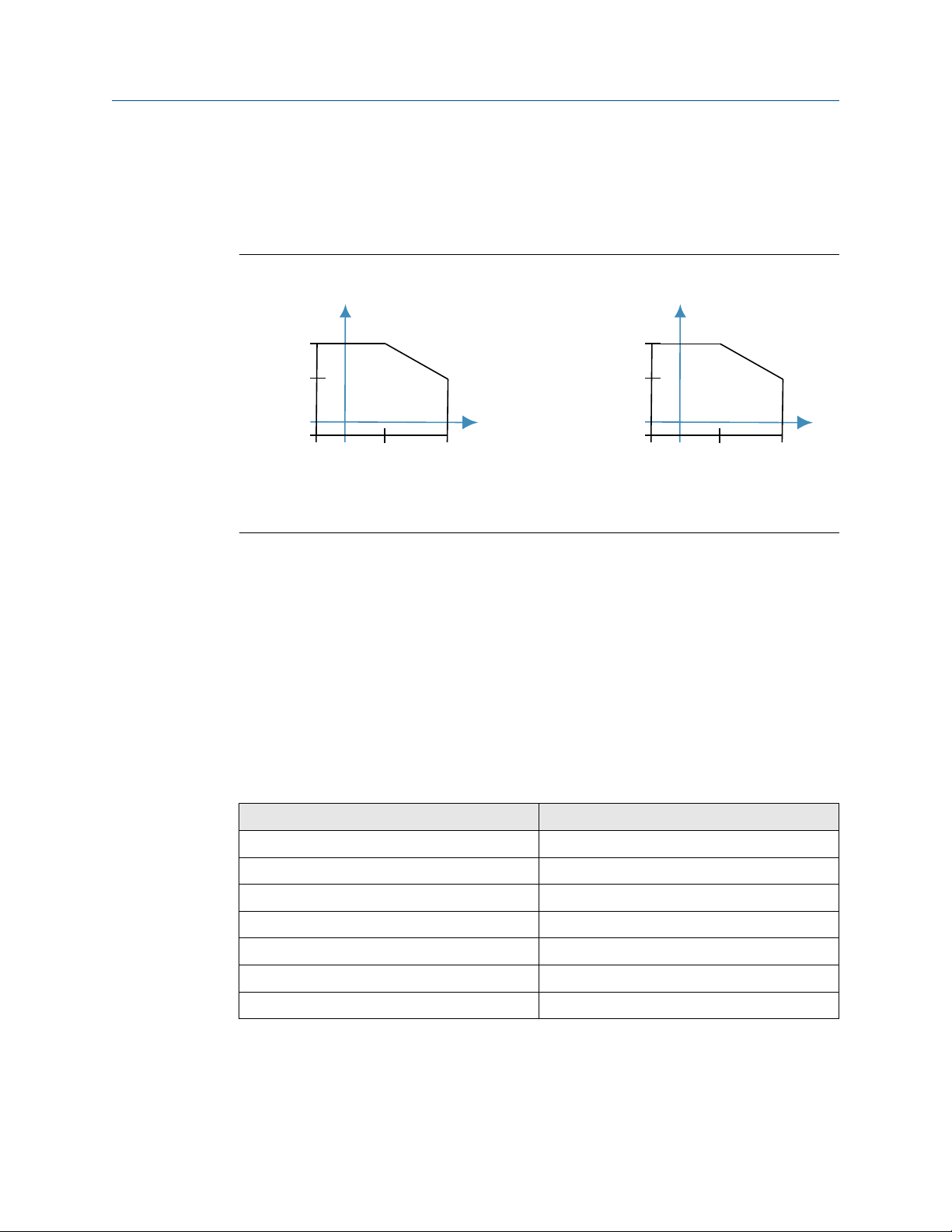
1450 (100)
1160 (80)
-40
(-40)32(0)
122
(50)
302
(150)
-14.5 (-1.0)
2160***S
1450 (100)
885 (61)
-94
(-70)32(0)
100
(38)
500
(260)
-14.5 (-1.0)
2160***E
A A
B B
Reference Manual Specifications and reference data
00809-0100-4160 May 2022
A.6 Environmental specifications
A.6.1 Maximum operating pressures
Figure A-1: Operating Pressures
A. Process pressure, psig (barg)
B. Process temperature, °F (°C)
The final rating depends on the process-wetted connection.
Threaded process connection
See Figure A-1.
Hygienic process connection
435 psig (30 barg)
Flanged process connection
The maximum operating pressure is the lower of the process pressure (Figure A-1) and
flange pressure rating (see Table A-2).
Table A-2: Maximum Flange Pressure Rating
Flange standard Stainless steel flanges
ASME B16.5 Class 150 275 psig
ASME B16.5 Class 300 720 psig
ASME B16.5 Class 600 1440 psig
EN1092-1 PN 10/16 16 barg
EN1092-1 PN 25/40 40 barg
EN1092-1 PN 63 63 barg
EN1092-1 PN 100 100 barg
(2)
(2)
(2)
(3)
(3)
(3)
(3)
(1)
(1) ASTM stainless steel.
(2) At 100 °F (38 °C), the pressure rating decreases with an increasing process temperature.
(3) At 122 °F (50 °C), the pressure rating decreases with an increasing process temperature.
Rosemount 2160 Wireless Level Detector 75
Page 76
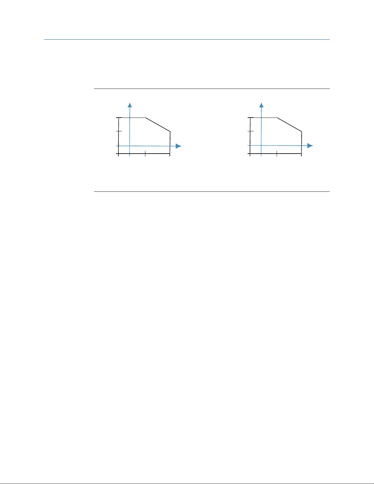
176 (80)
122 (50)
-40 (-40)
2160***S
176 (80)
149 (65)
-40 (-40)
2160***E
32 (0) 32 (0)
-40
(-40)32(0)
122
(50)
302
(150)
-94
(-70)
32
(0)
176
(80)
500
(260)
Specifications and reference data Reference Manual
May 2022 00809-0100-4160
A.6.2 Maximum and minimum operating temperatures
See Figure A-2 for the maximum and minimum operating temperatures.
Figure A-2: Operating Temperatures
A. Ambient Temperature, °F (°C)
B. Process Temperature, °F (°C)
76 Reference Manual
Page 77
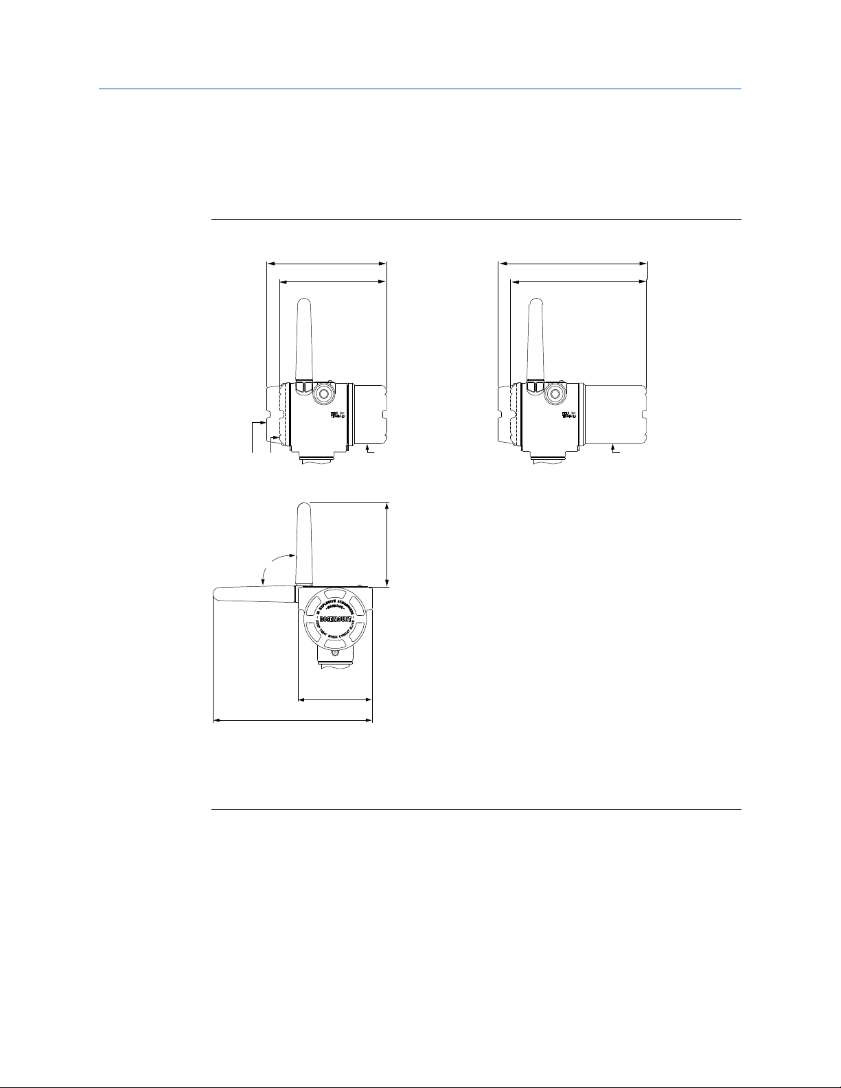
9.2 (233)
4.2 (107)
90°
4.8
(121)
8.4 (212)
7.7 (196)
6.7 (170)
6.1 (154)
D
C
A B
Reference Manual Specifications and reference data
00809-0100-4160 May 2022
A.7 Dimensional drawings
Refer to the Type 1 Drawing on the Rosemount 2160 web page for dimensions of the Oring seal (BSPP) versions.
Figure A-3: Housing and Antenna
A. LCD display (option M5)
B. No LCD display
Black Power Module cover (option WK1)
C.
D. Blue Power Module cover (option WK2)
Rosemount 2160 Wireless Level Detector 77
Page 78
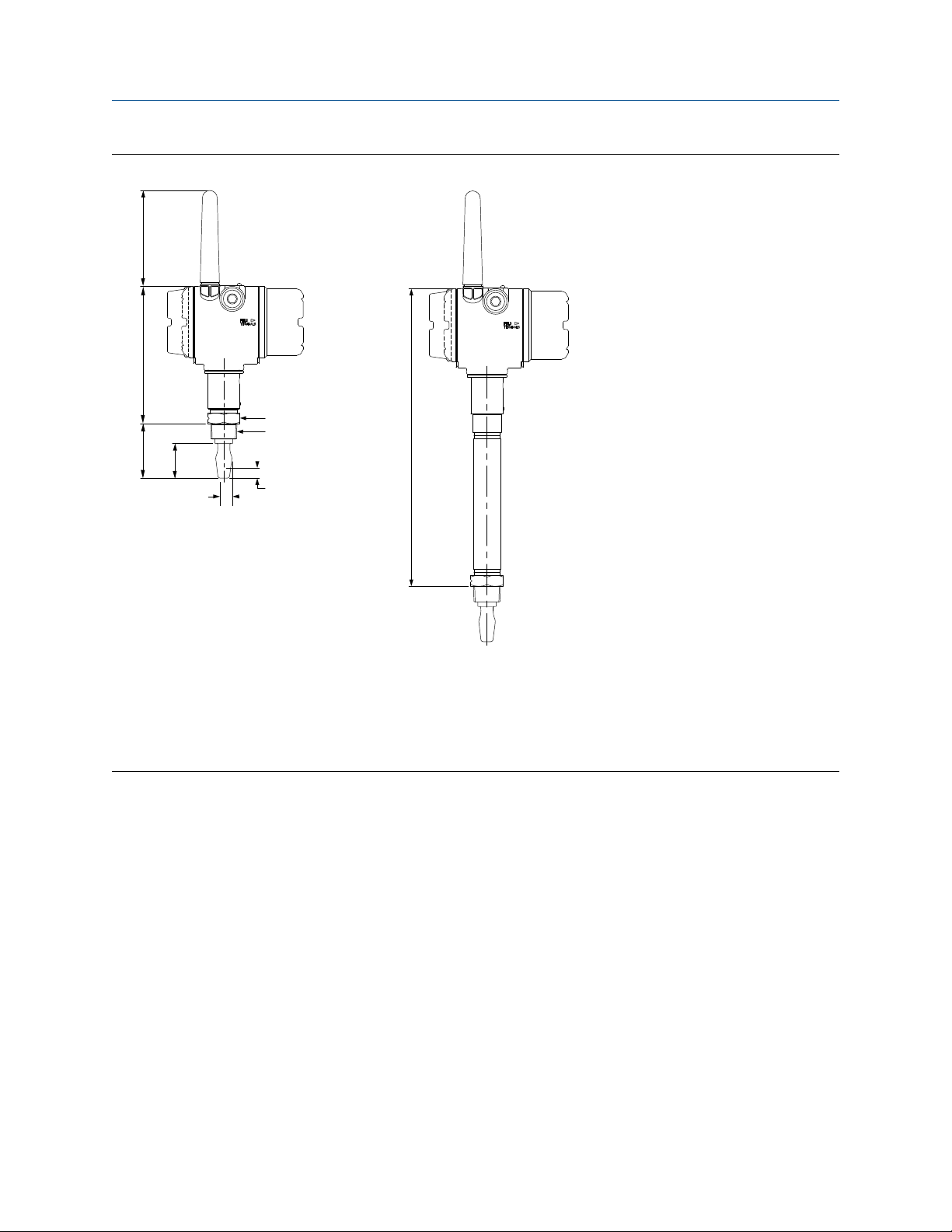
2.7
(69)
6.8
(172)
4.8
(121)
1.7
(44)
2160***S
C
D
A
B
14.5
(369)
2160***E
Specifications and reference data Reference Manual
May 2022 00809-0100-4160
Figure A-4: Threaded Process Connections (Standard Fork Length)
A. 1.6 (40) A/F hexagon
B. ¾- or 1-in. thread
C. 0.5 (13) switchpoint (when mounted vertically)
D.
0.5 (13) switchpoint (when mounted horizontally)
Dimensions are in inches (millimeters).
78 Reference Manual
Page 79
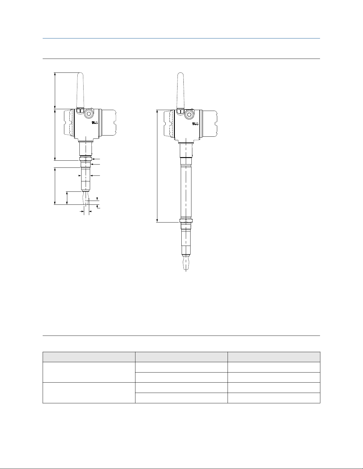
C
A
D
E
F
6.8
(172)
4.8
(121)
2160***S
14.4
(367)
2160***E
1.7
(44)
B
Reference Manual Specifications and reference data
00809-0100-4160 May 2022
Figure A-5: Threaded Process Connections (Extended Fork Length)
A. 1.6 (40) A/F hexagon
B. ¾- or 1-in. thread
C. See
D. 0.5 (13) switchpoint (when mounted vertically)
Table A-3 for dimensions
E. 0.5 (13) switchpoint (when mounted horizontally)
F. Customer specified fork length (see Table A-1)
Dimensions are in inches (millimeters).
Table A-3: Tube Diameters
Tube material Size Tube diameter in inches (mm)
316/316L ¾-in. 0.9 (22.9)
Alloy C/C-276 ¾-in. 0.84 (21.4)
Rosemount 2160 Wireless Level Detector 79
1-in. 1.125 (28.6)
1-in. 1.050 (26.7)
Page 80
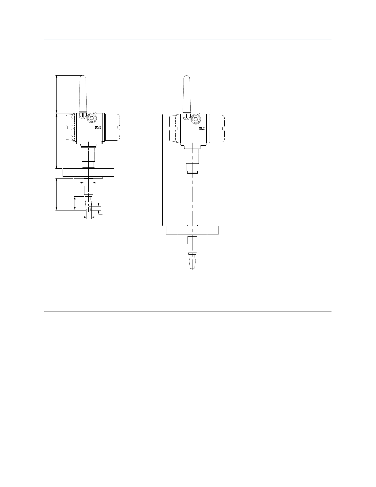
7.0
(177)
4.8
(121)
2160***S
13.8
(351)
2160***E
4.0
(102)
A
B
C
1.7
(44)
Specifications and reference data Reference Manual
May 2022 00809-0100-4160
Figure A-6: Flanged Process Connections (Standard Fork Length)
A. Ø0.9 (23) for 1-in. flange; Ø1.14 (29) for 1½-in. or larger flange
B. 0.5 (13) switchpoint (when mounted vertically)
0.5 (13) switchpoint (when mounted horizontally)
C.
Dimensions are in inches (millimeters).
80 Reference Manual
Page 81
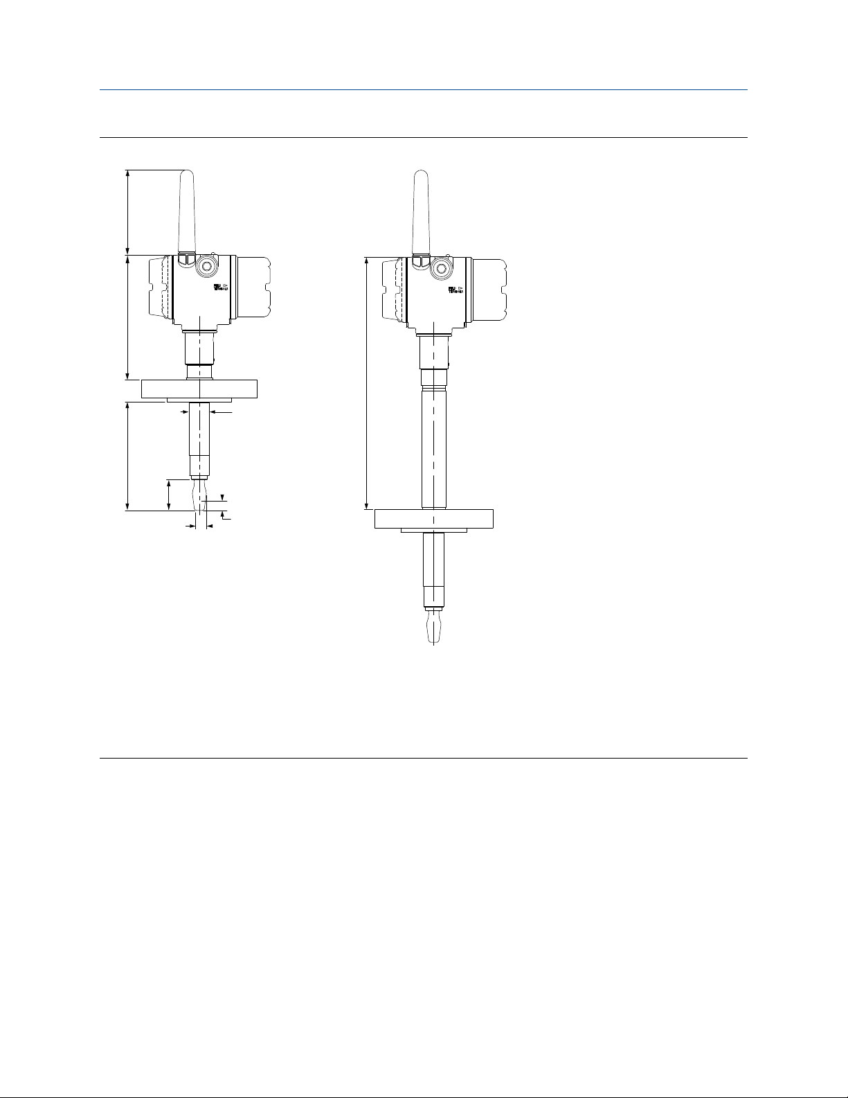
7.0
(177)
4.8
(121)
2160***S
13.8
(351)
2160***E
D
A
B
C
1.7
(44)
Reference Manual Specifications and reference data
00809-0100-4160 May 2022
Figure A-7: Flanged Process Connections (Extended Fork Length)
A. Ø0.9 (23) for 1-in. flange; Ø1.14 (29) for 1½-in. or larger flange
B. 0.5 (13) switchpoint (when mounted vertically)
0.5 (13) switchpoint (when mounted horizontally)
C.
D. Customer specified fork length (see Table A-1)
Dimensions are in inches (millimeters).
Rosemount 2160 Wireless Level Detector 81
Page 82
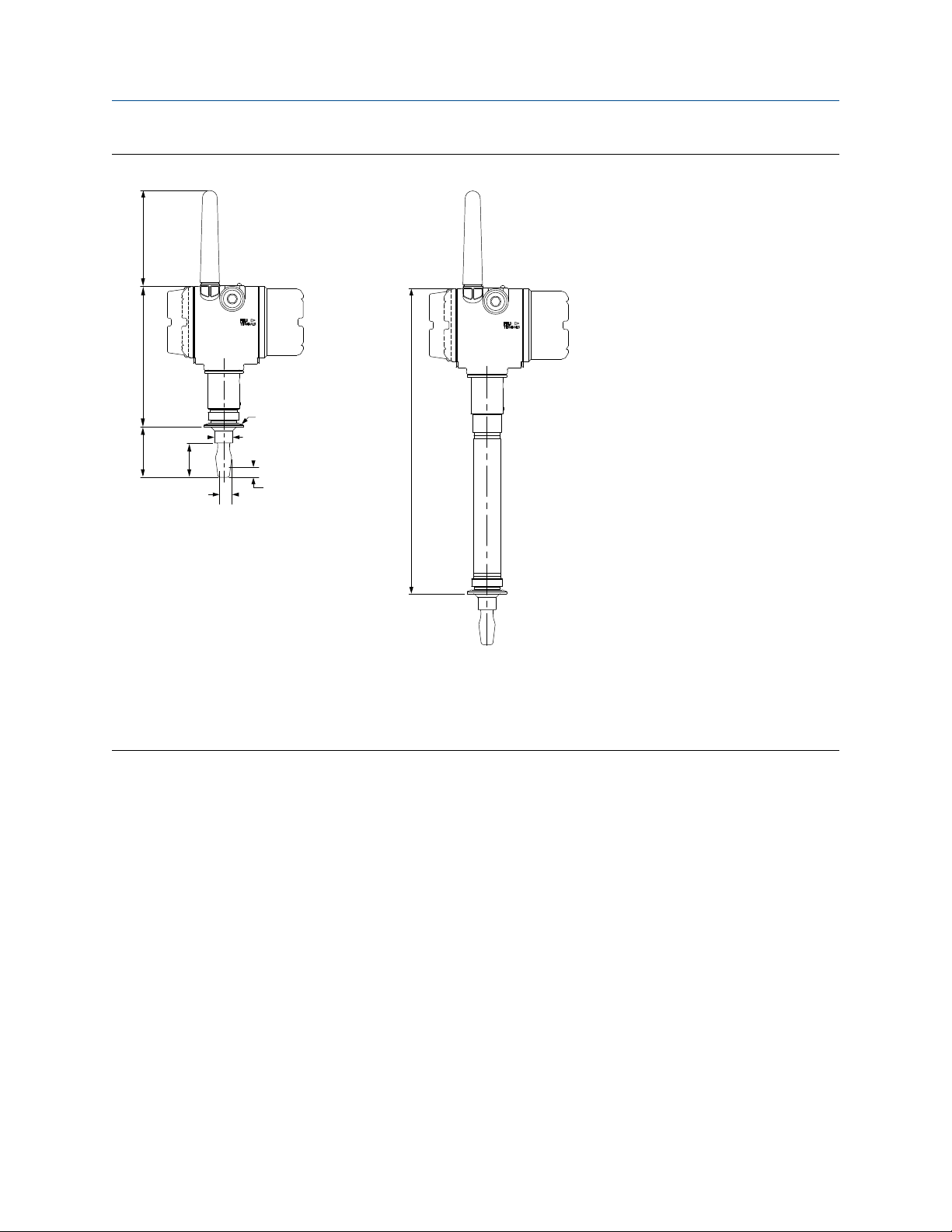
7.1
(179)
2.5
(64)
1.7
(44)
4.8
(121)
2160***S
14.7
(374)
2160***E
Ø0.9 (Ø23)
B
A
C
Specifications and reference data Reference Manual
May 2022 00809-0100-4160
Figure A-8: Tri Clamp Process Connections (Standard Fork Length)
A. ½-in. (38) or 2-in. (52) Tri Clamp
B. 0.5 (13) switchpoint (when mounted vertically)
C.
0.5 (13) switchpoint (when mounted horizontally)
Dimensions are in inches (millimeters).
82 Reference Manual
Page 83
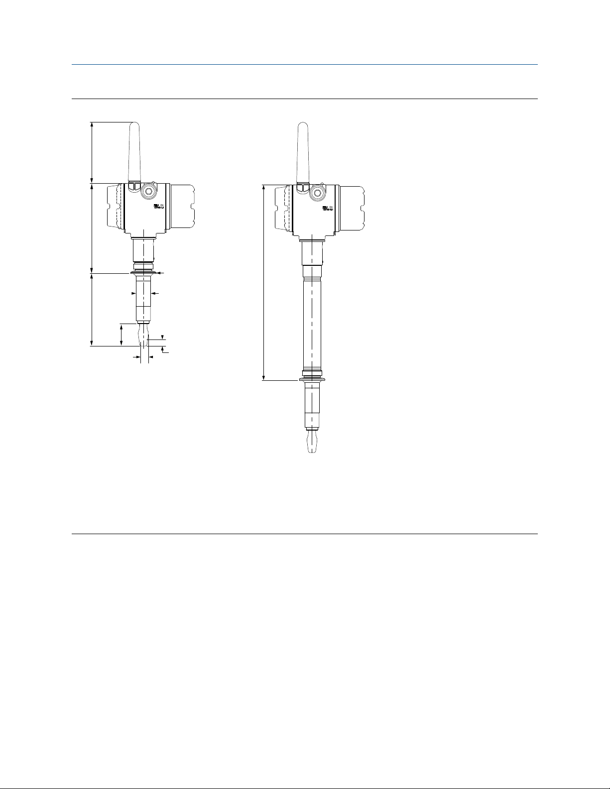
7.1
(179)
D
4.8
(121)
2160***S
14.7
(374)
2160***E
A
1.7
(44)
C
B
Ø1.125
(Ø28.6)
Reference Manual Specifications and reference data
00809-0100-4160 May 2022
Figure A-9: Tri Clamp Process Connections (Extended Fork Length)
A. ½-in. (38) or 2-in. (52) Tri Clamp
B.
0.5 (13) switchpoint (when mounted vertically)
0.5 (13) switchpoint (when mounted horizontally)
C.
D. Customer specified fork length (see Table A-1)
Dimensions are in inches (millimeters).
Rosemount 2160 Wireless Level Detector 83
Page 84

Specifications and reference data Reference Manual
May 2022 00809-0100-4160
84 Reference Manual
Page 85

Reference Manual Configuration parameters
00809-0100-4160 May 2022
B Configuration parameters
B.1 Manual setup
B.1.1 Wireless
Network ID
Identification number that tells the device which network it belongs to. Obtained from the
network administrator.
Join key
A kind of password that the device uses to join the network. Obtained from the network
administrator. All sections must contain the same number of characters.
Broadcast information
Message content
Which content (HART command) to broadcast for a message.
Message variables
Which variables that are included in the content.
Trigger mode
How message will be triggered.
Trigger level
At which level message will be triggered.
First and trigger variable
The 1st variable contained within message which also will be used to trigger a broadcast.
Triggered update rate
This defines how often the broadcast message is sent to the gateway after a user defined
trigger level threshold has been crossed. Faster update rates have an impact on the total
communications traffic on the network, and power module life.
Default update rate
This defines how often the broadcast message is sent to the gateway. Faster update rates
have an impact on the total communications traffic on the network, and power module
life.
Rosemount 2160 Wireless Level Detector 85
Page 86

Configuration parameters Reference Manual
May 2022 00809-0100-4160
B.1.2 Operation
Application
Operation mode
The Rosemount 2160 has three operation modes:
Table B-1: Operation Modes
Option Description
Standard Default operation mode for no sensor fault detection.
Enhanced (Fault=WET) Output is forced to Wet when fault detected.
Enhanced (Fault=DRY) Output is forced to Dry when fault detected.
Sensor output delay
When the Rosemount 2160 detects a change in process conditions from wet-to-dry or dryto-wet, the Sensor Output Delay parameter causes a delay of up to 3600 seconds before a
new process condition is indicated in the process variables.
If, for example, there are waves in a tank, then the Rosemount 2160 may intermittently
detect a change in process conditions. The sensor output delay ensures that the fork of the
level detector is dry or wet for a period before switching.
Depending on the application, a suitable delay can prevent constant switching of the
output state.
Media density
The vibration frequency of the fork sensor varies depending on the density of the process
liquid. For higher accuracy of switching points, to select one of the following options:
Table B-2: Media Density Options
Option Description
Normal Select when the specific gravity of the process liquid is between
0.7 and 2.0.
Low Select when the specific gravity of the process liquid is less than
0.7.
High Select when the specific gravity of the process liquid is greater
than 2.0.
Sensor
Sensor stabilization time
The time needed for the fork sensor to reach a stable vibration may vary depending on the
process conditions. Sensor Stabilization Time sets a delay before taking a frequency
measurement.
The default setting is 60 ms. It can be set to a time in the range 20 to 1000 ms and is
adjustable in 20 ms steps. Alternatively, the setting AUTO is for the Rosemount 2160 to
automatically calculate a delay.
86 Reference Manual
Page 87

Reference Manual Configuration parameters
00809-0100-4160 May 2022
Measurement time
The time needed for the fork sensor to take an accurate measurement, after reaching a
stable vibration, may vary depending on the process conditions. Measurement Time sets a
delay before taking a frequency measurement.
The default setting is "60 ms". It can be set to a time in the range 20 to 1000 ms and is
adjustable in 20 ms steps. Alternatively, the setting "AUTO" is for the Rosemount 2160 to
automatically calculate a delay.
Allowable change in fork frequency
When the level detector is re-calibrated in the field, a comparison is made between the
new dry fork frequency and original factory-set Dry Fork Frequency value. If the difference
is greater than the allowable change value, the re-calibration is rejected. Check the fork for
damage, corrosion, or coating, and clean the fork if necessary before re-trying.
The default setting is 100 Hz. It can be set to a value in the range 1 to 254 Hz.
Sensor fault delay
When the level detector is operating in Enhanced Mode and detects a fork sensor fault,
Sensor State indicates a fault state after a delay set by Sensor Fault Delay.
The default setting is 600 seconds. It can be set to value in the range 0 to 3600 seconds.
Note
When the level detector is operating in Normal mode, a fork sensor fault is not detected
and Sensor State continues to indicate a valid state.
B.1.3 Display
Display mode
The display can be configured to different display modes: Disabled, On Demand, or
Periodic.
Table B-3: Display Modes
Option Description
Disabled The display is always turned off.
On Demand The display is by default turned off. Selected variable screens will only
Periodic The display shows selected variable screens in a periodic sequence. A new
Display items
appear in the end of the diagnostic button screen sequence.
screen will appear on each wireless update.
The optional LCD display can be configured to show up to four variables:
• Output State variable (default selection)
• Sensor Frequency variable (default selection)
• Electronics Temperature variable
Rosemount 2160 Wireless Level Detector 87
Page 88

Configuration parameters Reference Manual
May 2022 00809-0100-4160
• Supply Voltage variable
If more than one variable is selected, the display will toggle between the values of those
variables.
B.1.4 Data logging
The level detector can store a series of 12 data collection (sample) points for a chosen
device variable.
Measurement and status log
There are two alternatives for data collection:
• Log data on change - where the sampling is triggered by a changing value.
• Continuous logging - where the sampling is triggered at a regular interval (sample
interval).
Configure data history
Enable data history trending by selecting Enable Single Data Point Trending
(recommended) or Enable Filtered Trending.
After data history trending is enabled, select a device variable to be logged, and then the
sample interval (4 to 7200 seconds).
B.1.5 Security
Write protection
The level detector can prevent changes to the configuration by activating this security
function.
B.1.6 Device temperature
Temperature units
The Device Temperature menu displays the following menu items:
Electronics temp
This is the live measurement of the temperature inside the electronics housing.
Electronics temperature status
This indicates a valid or fault status for the electronics temperature measurement.
Unit
The units for temperature can be changed to Fahrenheit (°F) or Celsius (°C) using the Unit
parameter.
Maximum and minimum
These show the highest and lowest temperature that has been measured by the device.
88 Reference Manual
Page 89

Reference Manual Configuration parameters
00809-0100-4160 May 2022
B.1.7 Device information
Tag
Identifier of up to 8 characters for the device used by host system. The tag is typically a
reference number, location, or duty description.
Long tag
Identifier of up to 32 characters for the device used by host system. It is recommended to
enter both a short and a long tag (they may be the same).
Descriptor
The 16-character descriptor field can be used for any purpose.
Message
The 32-character message field can be used for any purpose, such as providing details of
the last configuration change.
Date
The date field can be used for any purpose, for example to save the date of the last
configuration change.
Country
This can be used for any purpose and does not affect the operation of the device.
SI unit control
Allows non-SI Units to be displayed.
B.1.8 Power
Power mode
Configures the device to take periodic measurements to conserve battery life, or to take
continuous measurements.
Note
Always On mode is only recommended for devices connected to line power.
Power source
Optimizes the device to make use of the power source to which it is attached.
Rosemount 2160 Wireless Level Detector 89
Page 90
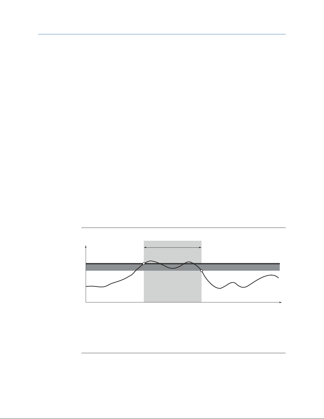
A
C
D
E
F
B
Configuration parameters Reference Manual
May 2022 00809-0100-4160
B.2 Alert setup
B.2.1 Process alerts
Process alerts allow the Rosemount 2160 to indicate when a pre-set data point is
exceeded.
Alerts can be set for the following device variables:
• Output State
• Sensor Frequency
• Electronics Temperature
• Supply Voltage
An active alert is displayed on the status screen of a host or on the optional LCD display.
When the value returns within range, an alert is reset.
Mode
Select “on” to enable the alert, or “off” to switch the alert off.
Variable
Select Output State, Sensor Frequency, Electronics Temperature, or Supply Voltage.
Direction
Rising alert (see Figure B-1) or falling alert (see Figure B-2).
Figure B-1: Example 1: Rising Alert
A. Units of measurement
B. Time
C.
Alert set point
D. Deadband
E. Assigned value
F. Alert "ON"
90 Reference Manual
Page 91
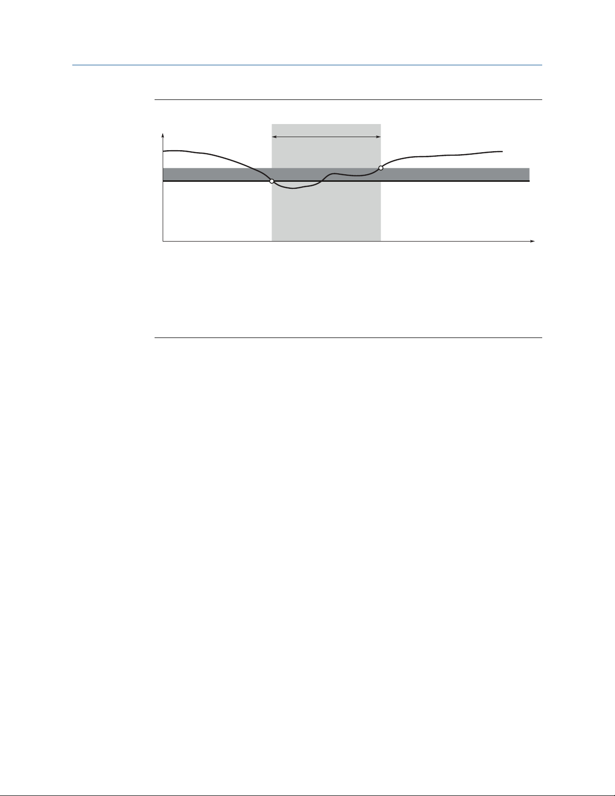
A
C
D
E
F
B
Reference Manual Configuration parameters
00809-0100-4160 May 2022
Figure B-2: Example 2: Falling Alert
A. Units of measurement
B. Time
C. Deadband
D. Alert set point
E. Assigned value
F. Alert "ON"
Limit
Alert set point (in same units as the variable).
Deadband
Hysteresis data point (in same units as the variable) for transition from deadband zone to
new alert state.
Rosemount 2160 Wireless Level Detector 91
Page 92

00809-0100-4160
Rev. AE
2022
For more information:
©
2022 Emerson. All rights reserved.
Emerson.com
Emerson Terms and Conditions of Sale are available upon
request. The Emerson logo is a trademark and service mark of
Emerson Electric Co. Rosemount is a mark of one of the
Emerson family of companies. All other marks are the property
of their respective owners.
 Loading...