

Page 1
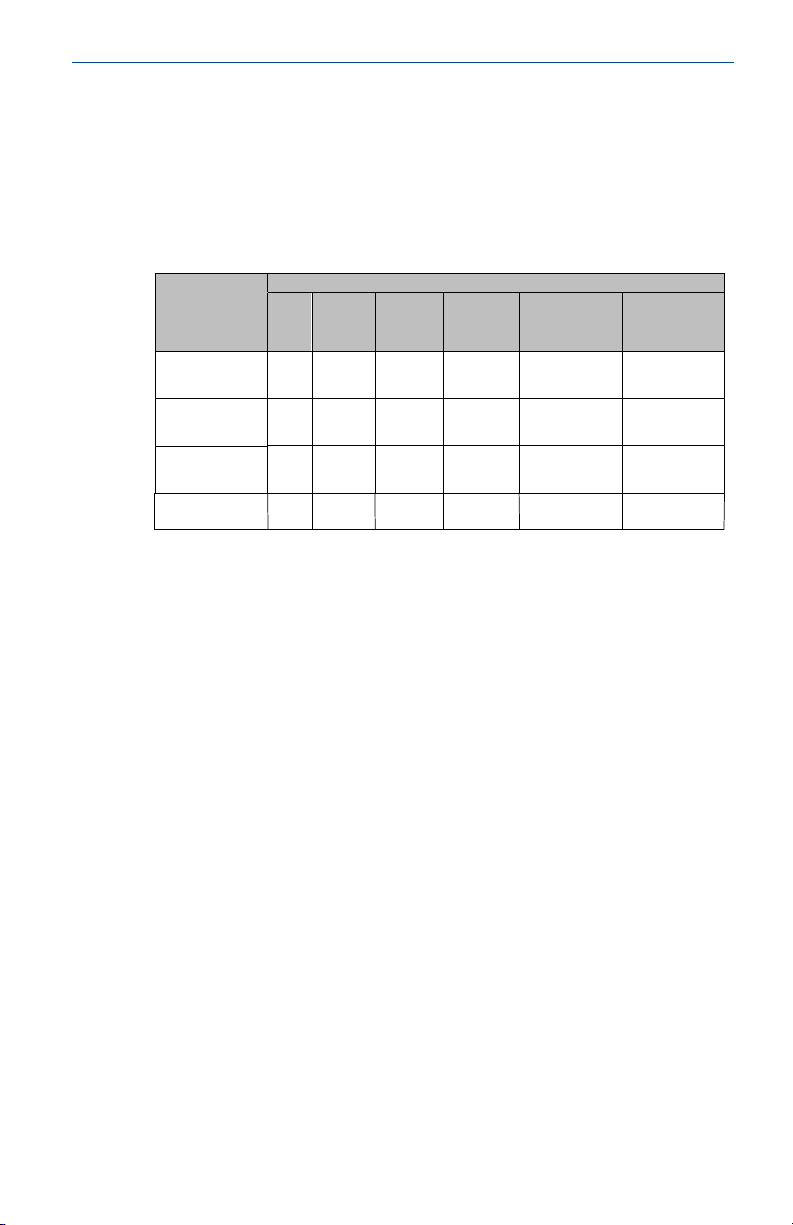
Quick Start Guide
00825-0100-2501, Rev AA
October 2019
Rosemount™ 2501 Solids Level Switch
Rotating Paddle
Page 2

Quick Start Guide October 2019
Contents
Introduction.................................................................................................................................3
Mechanical installation...............................................................................................................11
Electrical installation.................................................................................................................. 20
Configuration.............................................................................................................................25
Operation...................................................................................................................................28
Maintenance.............................................................................................................................. 31
Product certifications................................................................................................................. 33
2 Quick Start Guide
Page 3

October 2019 Quick Start Guide
1 Introduction
The level switch detects the presence and absence of a process media at its
installation point, and reports it as a switched electrical output.
Note
Other language versions of this Quick Start Guide can be found at
Emerson.com/Rosemount.
1.1 Safety messages
NOTICE
Read this manual before working with the product. For personal and system
safety, and for optimum product performance, ensure you thoroughly
understand the contents before installing, using, or maintaining this
product.
For technical assistance, contacts are listed below:
Customer Central
Technical support, quoting, and order-related questions.
• United States - 1-800-999-9307 (7:00 am to 7:00 pm CST)
• Asia Pacific- 65 777 8211
North American Response Center
Equipment service needs.
• 1-800-654-7768 (24 hours a day — includes Canada)
• Outside of these areas, contact your local Emerson representative.
WARNING
Physical access
Unauthorized personnel may potentially cause significant damage to and/or
misconfiguration of end users’ equipment. This could be intentional or
unintentional and needs to be protected against.
Physical security is an important part of any security program and
fundamental to protecting your system. Restrict physical access by
unauthorized personnel to protect end users’ assets. This is true for all
systems used within the facility.
Quick Start Guide 3
Page 4

Quick Start Guide October 2019
WARNING
Failure to follow safe installation and servicing guidelines could result in
death or serious injury.
• Ensure the level switch is installed by qualified personnel and in
accordance with applicable code of practice.
• Use the level switch only as specified in this manual. Failure to do so may
impair the protection provided by the level switch.
Explosions could result in death or serious injury.
• The level switch must only be installed and operated in non-hazardous
(ordinary) locations.
Electrical shock could cause death or serious injury.
• Avoid contact with the leads and terminals. High voltage that may be
present on leads can cause electrical shock.
• Ensure the power to the level switch is off, and the lines to any other
external power source are disconnected or not powered while wiring the
level switch.
• Ensure the wiring is suitable for the electrical current and the insulation is
suitable for the voltage, temperature, and environment.
Process leaks could result in death or serious injury.
• Ensure the level switch is handled carefully. If the process seal is
damaged, gas or dust might escape from the silo (or other vessel)
Any substitution of non-recognized parts may jeopardize safety. Repair,
e.g. substitution of components, etc. may also jeopardize safety and is
under no circumstances allowed.
• Unauthorized changes to the product are strictly prohibited as they may
unintentionally and unpredictably alter performance and jeopardize
safety. Unauthorized changes that interfere with the integrity of the
welds or flanges, such as making additional perforations, compromise
product integrity and safety. Equipment ratings and certifications are no
longer valid on any products that have been damaged or modified
without the prior written permission of Emerson. Any continued use of
product that has been damaged or modified without the written
authorization is at the customer’s sole risk and expense.
4 Quick Start Guide
Page 5

October 2019 Quick Start Guide
CAUTION
The products described in this document are NOT designed for nuclearqualified applications.
• Using non-nuclear qualified products in applications that require
nuclear-qualified hardware or products may cause inaccurate readings.
• For information on Rosemount nuclear-qualified products, contact your
local Emerson Sales Representative.
Individuals who handle products exposed to a hazardous substance can
avoid injury if they are informed of and understand the hazard.
• If the product being returned was exposed to a hazardous substance as
defined by Occupational Safety and Health Administration (OSHA), a
copy of the required Safety Data Sheet (SDS) for each hazardous
substance identified must be included with the returned level switch.
1.2 Applications
A Rosemount™ 2501 Solids Level Switch is used for monitoring the level of
bulk materials in all types of containers and silos.
The level switch can be equipped for process overpressure
pressure, and also for very high or low process temperatures.
The level switch can be used with different paddle shapes and sizes to
monitor fine and medium solids in bulk materials. See Table 4-1 for a guide
to the minimum density requirements.
Typical applications are:
• Building materials
— Lime, extruded polystyrene foam (XPS), molding sand, etc.
• Food and beverage
— Milk powder, flour, salt, etc.
• Plastics
— Plastic granulates, etc.
• Timber
• Chemicals
The level switch has a threaded, flanged, or Tri Clamp process connection for
mounting it onto a silo (or other vessel). You can mount it on a side wall of
the silo, so that it is level with the filling limit to be monitored. Alternatively,
(1)
and low
(1)
Overpressure (or blast overpressure) is the pressure caused by a shock wave over and
above normal atmospheric pressure.
Quick Start Guide 5
Page 6
A B C
D
E
F
G
Quick Start Guide October 2019
if it has an extended length, mount it vertically on top of a silo to monitor the
maximum filling limit.
The length of the paddle can be up to 158 in. (4 m) with an extension tube or
up to 394 in. (10 m) with an extension rope.
The use of a sliding sleeve is recommended so that the switching point can
be changed easily during the live operation of the level switch.
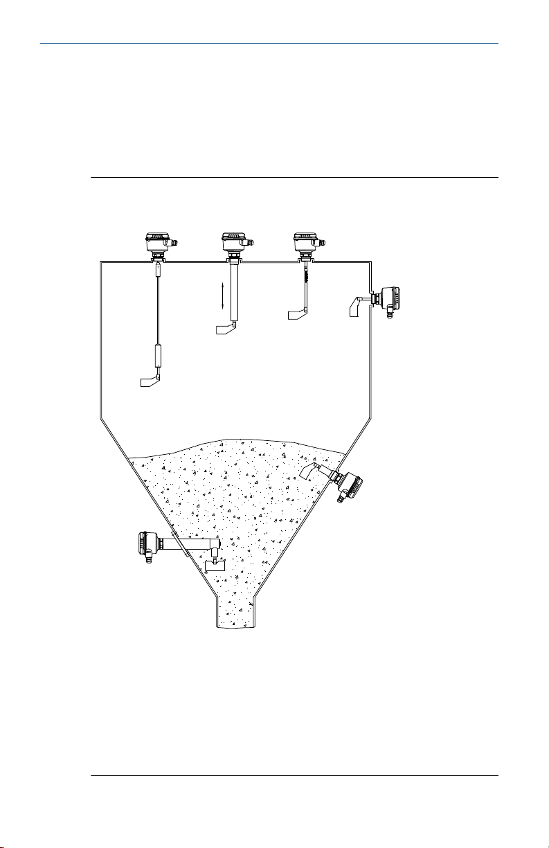
Figure 1-1: Typical Installation Examples
A. Rosemount 2501R or 2501S with the rope-extended fork length
B. Rosemount 2501M with the tube extension and optional sliding sleeve
C. Rosemount 2501L with the pendulum shaft
D. Rosemount 2501L with the boot-shaped vane paddle
E. Rosemount 2501J
F. Rosemount 2501K
G. Optional sliding sleeve
6 Quick Start Guide
Page 7
B
A C D
October 2019 Quick Start Guide
1.3 Measurement principles
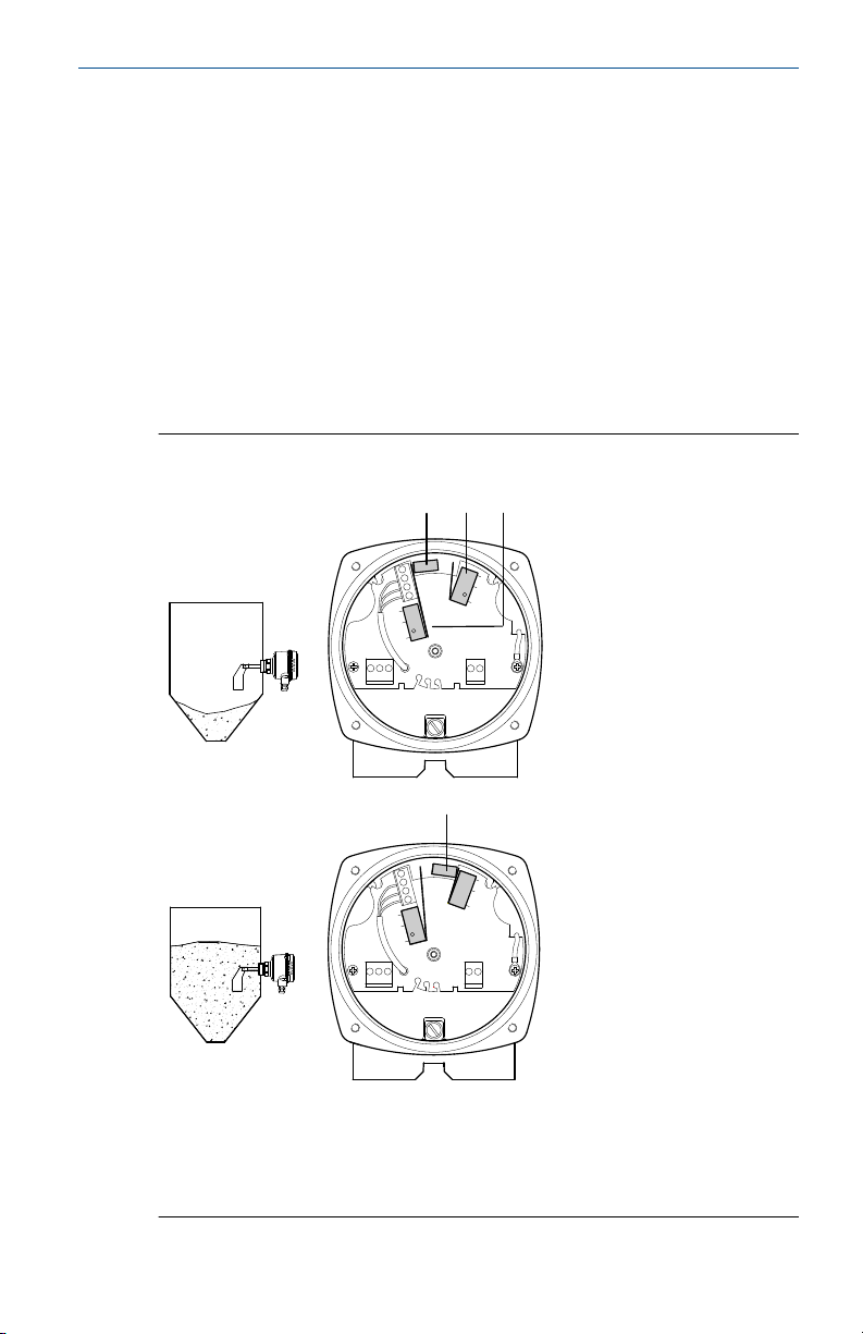
Using a synchronous motor, the paddle (measuring vane) is driven to rotate
360 degrees.
When the vane of the paddle is not covered by a solids medium, a spring
pulls the motor and it switches a lug to the left position (Figure 1-2, top
illustration). The signal output indicates an 'uncovered' state and the motor
rotates the paddle.
When a solids medium covers the vane of the paddle, and causes the
rotation to stop, the lug is switched to the right position (Figure 1-2, bottom
illustration). The signal output indicates a 'covered' state due to a rising level
of material, and the motor is stopped until the vane becomes uncovered.
Figure 1-2: Switching Lug Function
A. Switching lug in left position ('uncovered' state)
B. Switching lug in right position ('covered' state)
C. Switch for stopping the motor
D. Switch for signal output
Quick Start Guide 7
Page 8
Quick Start Guide October 2019
The electrical outputs vary depending on the power supply selected when
the Rosemount 2501 was ordered. See the Rosemount 2501 Product Data
Sheet for the Power Supply option codes, and Electronics for an overview of
the outputs.
1.4 Functions
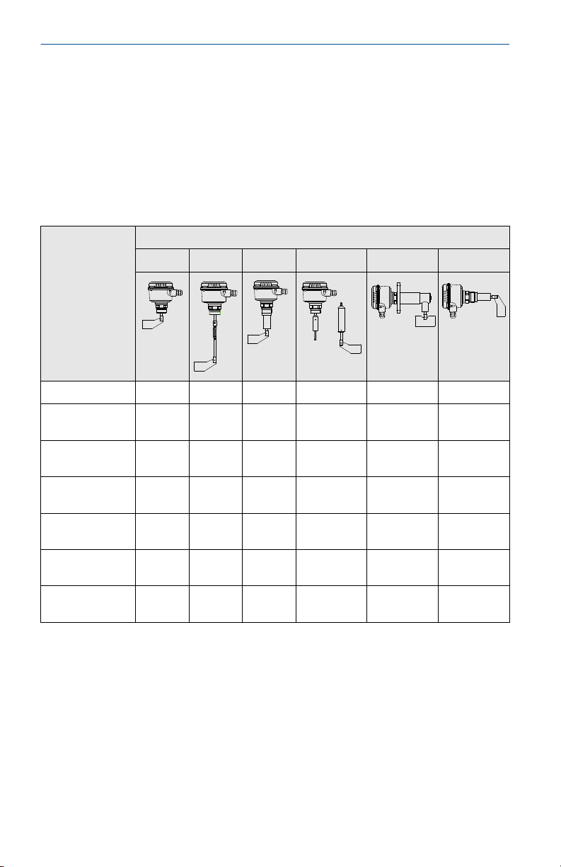
1.4.1 Selection guide
Table 1-1: Rosemount 2501 Selection Guide
Type of
installation
Full silo detection * *
On-demand
detection
Empty silo
detection
Vertical
mounting
Angled mounting
(top)
Horizontal
mounting
Angled mounting
(bottom)
(1) Consider the maximum permitted mechanical traction force.
(2) Available only with the "bearing at tube end" option.
2501L 2501M 2501R 2501S 2501K 2501J
(1)
* *
* *
* * * *
* *
* * *
* *
Model option codes
* * * *
(1)
(1)
(1)
(2)
* *
* *
*
*
8 Quick Start Guide
Page 9
October 2019 Quick Start Guide
1.4.2 Shaft sealing and metal material
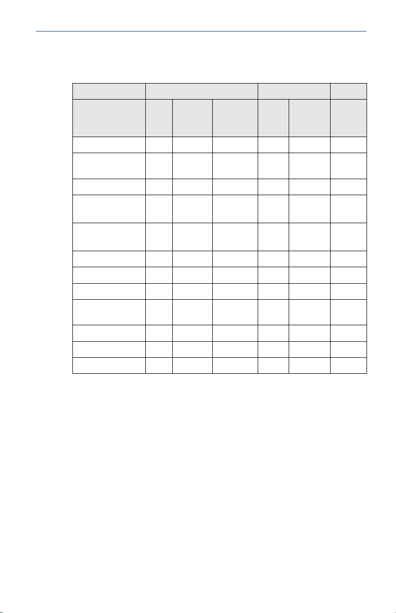
Table 1-2: Shaft Sealing and Metal Material
Application Sealing material
NBR FPM PTFE ALU
Animal feed press * * *
Synthetic granules,
* *
powders
Salt * * *
Dust filter
(for up to 392 °F)
Dust filter
* *
(for up to 302 °F)
Bitumen * *
Cement * *
Wood chip dryer * *
Pressure conveying
vessel, 8 bar
Sugar * *
Flour * *
Carbon black * *
(1)
Metal Bearing
* *
* *
(2)
SST 304
(1.4301)
(3)
SST
(1) Selection varies, depending on process temperature and pressure:
NBR: Maximums are 80 °C and 0.8 bar.
FPM: Maximums are 150 °C and 0.8 bar.
PTFE: Maximums are 250 °C and 0.8 bar, 80/150/250 °C and 5/10 bar.
(2) Aluminum.
(3) 316L (1.4404) stainless steel is recommended in particular cases.
Quick Start Guide 9
Page 10

Quick Start Guide October 2019
1.4.3 Electronics
Table 1-3: Electronics
Power supply SPDT
Ac
version
Dc
version
Universal
voltage
(1) Single-Pole-Double-Throw contacts.
(2) Double-Pole-Double-Throw contacts.
(3) Selectable Fail Safe High or Fail Safe Low alarm output. See Wiring the universal
(4) Adjustable time delay for the switched outputs.
24 or 48 Vac or
115 or 230 Vac
24 Vdc * - - - -
24 Vdc /
22 .. 230 Vac
voltage version and Jumper Settings for Fail Safe High or Low.
(1)
* - - - -
- * * * option
DPDT
(2)
FSH/
FSL
Output
(3)
delay
(4)
Fail safe alarm
Switched signal output
The ac-voltage or dc-voltage versions of the level switch output a 'covered
paddle' or 'uncovered paddle' status signal through SPDT relay contacts.
See Wiring the ac and dc voltage versions for details.
The universal-voltage version of the level switch outputs a 'covered paddle'
or 'uncovered paddle' status signal through DPDT relay contacts.
See Wiring the universal voltage version for details.
When using the universal-voltage version of the level switch, there is an
adjustable delay for the switched signal output. Setting a delay helps to
prevent false switching of the output when there is movement of the bulk
material in a silo (or other vessel). See Figure 4-1 for details.
Fail safe alarm
The fail-safe alarm option makes it possible for the level switch to indicate a
fault using the alarm relay.
The following faults are indicated:
• Motor failure
• Gear failure
• Electronics failure (for motor power supply)
• Supply voltage failure
• Terminal wiring defect
10 Quick Start Guide
Page 11

October 2019 Quick Start Guide
2 Mechanical installation
2.1 Mounting considerations
Before mounting the level switch on a silo (or other vessel), review the safety
and pre-mounting sections.
2.1.1 Safety
General safety
1. Installation of this equipment shall be carried out by suitably trained
personnel, in accordance with the applicable code of practice.
2. If equipment is likely to come into contact with aggressive
substances, it is the user’s responsibility to take suitable precautions
that prevent it from being adversely affected, thus ensuring the type
of protection is not compromised.
a. Aggressive substances: e.g. acidic liquids or gases that may
attack metals or solvents that may affect polymeric materials.
b. Suitable precautions: e.g. regular checks as part of routine
inspections or establishing from a material's data sheet that it
is resistant to specific chemicals.
3. It is the responsibility of the installer to:
a. Ensure the mechnical force exerted on the paddle by the bulk
solids does not exceed the maximum permitted for that
paddle. Refer to the technical specifications in the
Rosemount 2501 Product Data Sheet for further information.
b. Take protective measures, such as fitting an angled shield
(reverse V shape) to the silo or selecting an extension tube
option, when there are high mechanical forces.
c. Ensure that the process connection is tightened by the
correct amount of torque and sealed to prevent process
leaks.
4. Technical data
a. The Rosemount 2501 Product Data Sheet has all the technical
specifications. See Emerson.com/Rosemount for other
language versions.
Quick Start Guide 11
Page 12
Maximum 50 Nm (at 40 °C)
Maximum 500 Nm (at 40 °C)
Maximum 180 Nm (at 40 °C)
Stainless steel:
Aluminum:
Maximum 600 Nm (at 40 °C)
Maximum 250 Nm (at 40 °C)
Stainless steel:
Aluminum:
Quick Start Guide October 2019
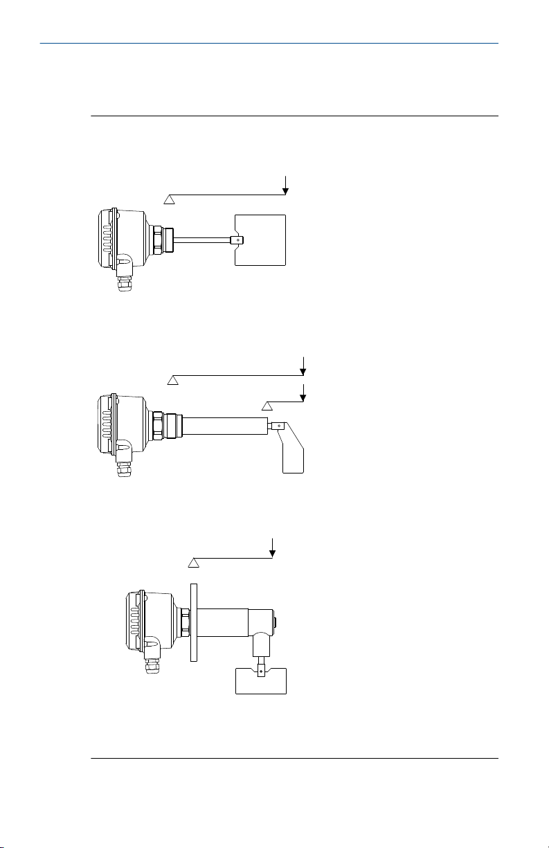
2.1.2 Mechanical load
See Figure 2-1 for the maximum loads supported by the level switch.
Figure 2-1: Maximum Permitted Mechanical Load
Rosemount 2501L
Rosemount 2501M and 2501J
Rosemount 2501M and 2501K
Rosemount 2501S
Contact Emerson for the maximum load of a Rosemount 2501S.
12 Quick Start Guide
Page 13
A
October 2019 Quick Start Guide
Note
Take protective measures, such as fitting an angled shield (reverse-V shape)
to the silo or selecting an extension tube option, when there are high
mechanical forces.
2.1.3 Mounting location
Take time to assess a suitable mounting location. Avoid mounting the level
switch near the filling point, internal structures, and walls of a silo (or other
vessel). When mounting the extended length versions of the level switch, it
is especially important to consider internal structures. Forcing the level
switch into a small or congested space risks damage to the sensor and could
impair the protection it provides.
2.1.4 Sliding sleeve
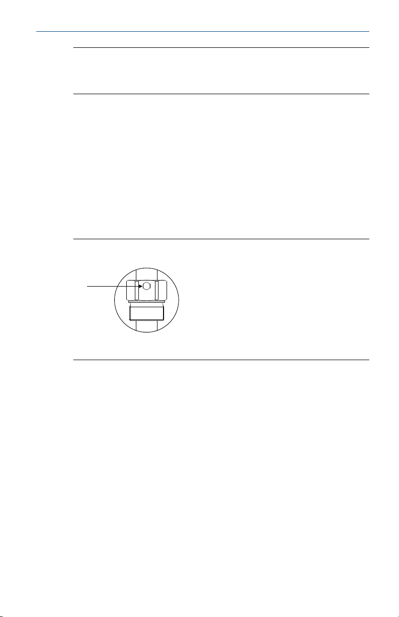
Tighten both M8 screws with a torque of 20 Nm to establish a seal and
maintain the process pressure. See Figure 2-2.
Figure 2-2: Sliding Sleeve, M8 Screws
A. Two off M8 screws
2.1.5 Flange mounting
A suitable gasket must be fitted to provide a seal when the flanges are
tightened.
2.1.6 Hygienic applications
The food-grade materials are suitable for use under normal and predictable
hygienic applications (according to directive 1935/2004 Art.3). There are
currently no hygienic certifications for the Rosemount 2501.
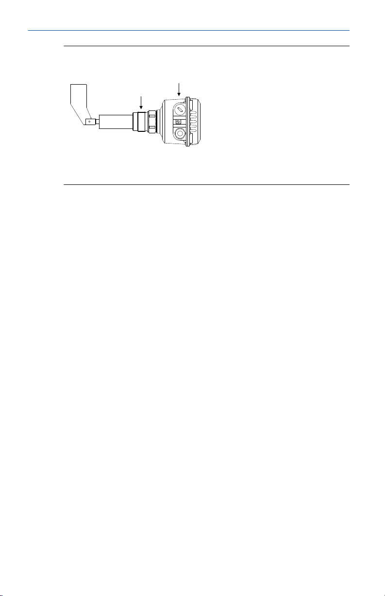
2.1.7 Rotatable housing
The housing of the level switch can be rotated against the threaded
connection after mounting.
Quick Start Guide 13
Page 14
A
B
Quick Start Guide October 2019
Figure 2-3: Housing Rotation
A. Threaded process connection
B. Rotatable housing
2.1.8 Orientation of cable glands
When the level switch is mounted horizontally, ensure the cable glands are
pointed downwards to avoid water getting inside the housing. Unused
conduit entries must be completely sealed with a suitably rated stopping
(blanking) plug.
2.1.9 Seals
Apply PTFE tape to the threaded process connection or use a flat gasket. This
is required for a silo (or other vessel) to maintain the process pressure.
2.1.10 Future maintenance
It is advisable to:
• Grease the screws of the housing cover (lid) when a corrosive
atmosphere is present.
• Use PTFE tape to avoid seizing of aluminum process connection thread
with the socket.
This will help prevent difficulties when the cover needs to be removed
during future maintenance tasks.
14 Quick Start Guide
Page 15
A
B
C
D
E
F
F
October 2019 Quick Start Guide
2.2 Mounting the level switch
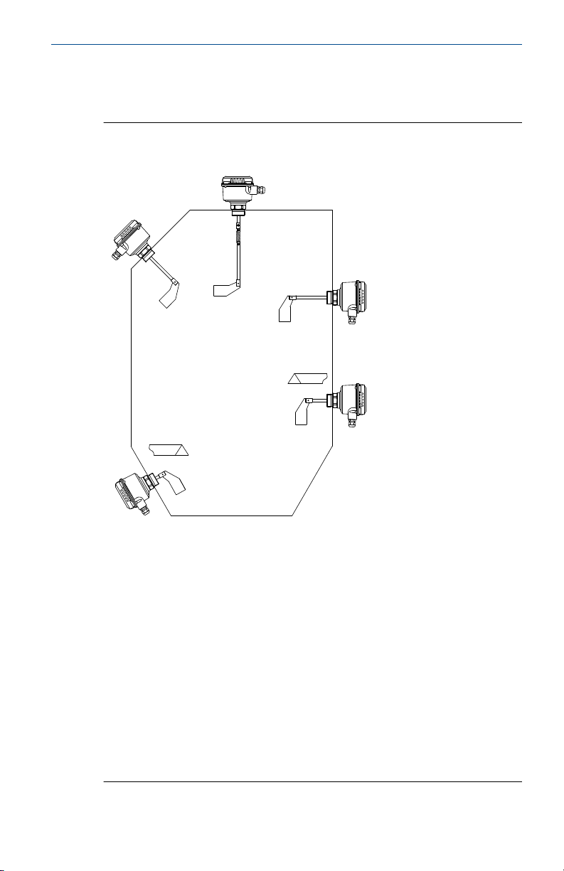
Figure 2-4 shows how the level switch should be mounted.
Figure 2-4: Rosemount 2501L Mounting Examples
A. Angled-mounting, at top of silo, for full-silo (overfill) detection.
Maximum L=23.62 in. (600 mm)
B. Vertical-mounting for full-silo (overfill) detection, with pendulum shaft or
rope-extension. Check the maximum load of the level switch
C. Horizontal-mounting, near top of silo, for full-silo (overfill) detection.
Maximum L=11.8 in. (300 mm)
D. Horizontal-mounting, near bottom of silo, for control (on demand)
detection. Maximum L=5.9 in. (150 mm)
E. Angled-mounting, at bottom of silo, for empty-silo (filling demand)
detection. Maximum L=11.8 in. (300 mm)
F. A protective shield is recommended depending on the load
The boot-shaped vane (paddle) is recommended for horizontal mountings
because it aligns to the movement of the solids material. See Mechanical
load and Sensitivity to check that the paddle meets the application limits.
Quick Start Guide 15
Page 16
A C
B
D
Quick Start Guide October 2019
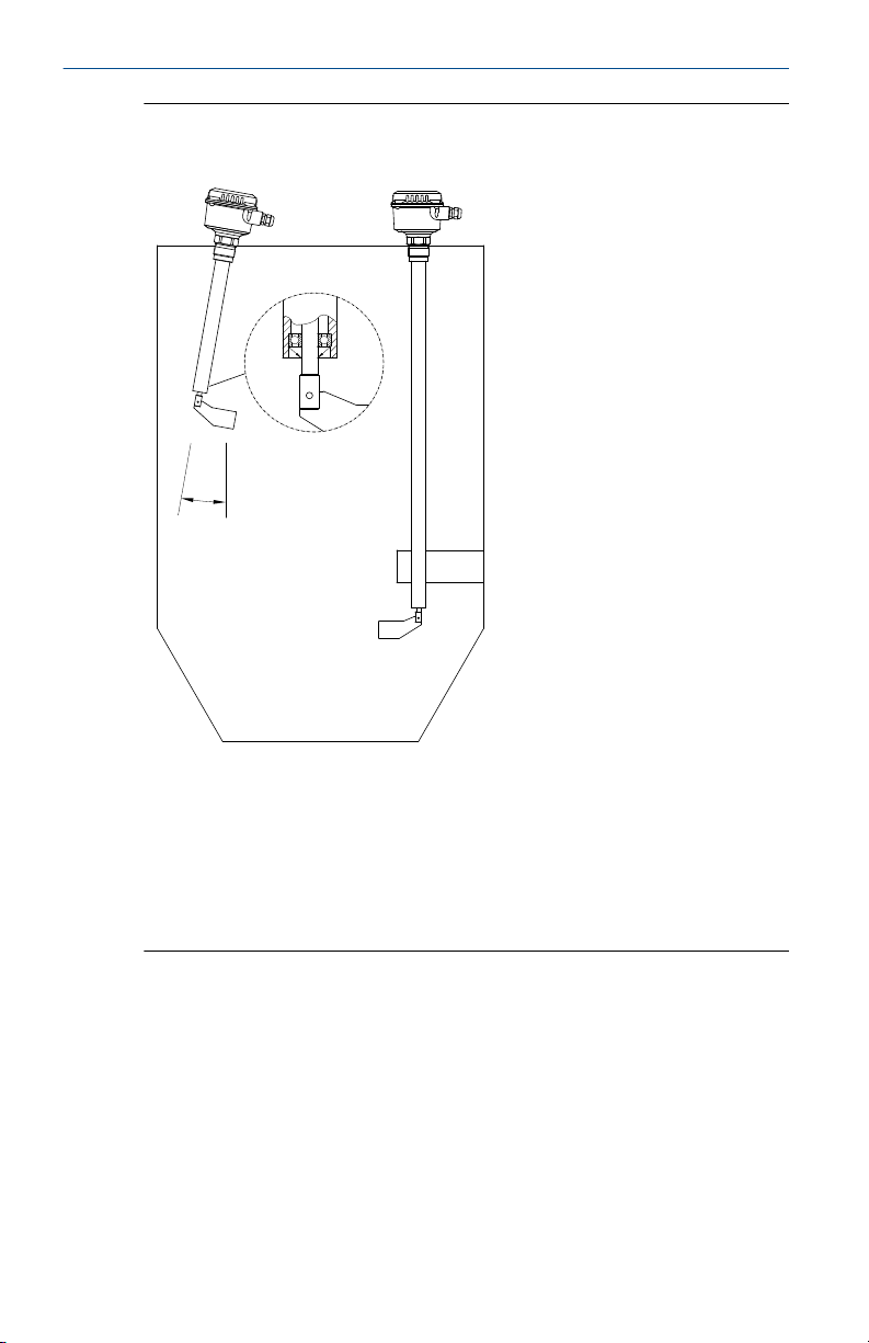
Figure 2-5: Rosemount 2501M Mounting Examples
A. Vertical-mounting for full-silo (overfill) detection with optional sliding
sleeve. Maximum L=118 in. (3000 mm)
B. The maximum angle of deviation from the normal vertical position is 10°
when using the "bearing at tube end" option
C. Vertical-mounting for full-silo (overfill) detection, with optional sliding
sleeve. Maximum L=158 in. (4000 mm)
D. Supports from the side of the silo are recommended
16 Quick Start Guide
Page 17
A B C
October 2019 Quick Start Guide
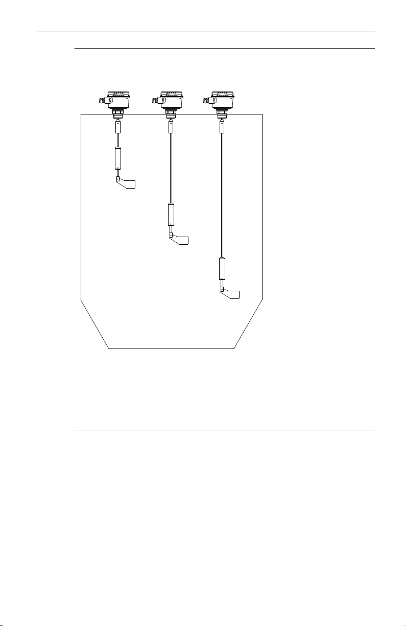
Figure 2-6: Rosemount 2501R and 2501S Mounting Examples
A. Full-silo (overfill) detection, with a rope extension
B. Demand detection, with a rope extension
C. Empty-silo (filling demand), detection with a rope extension
Maximum L=394 in. (10000 mm). See Mechanical load and Sensitivity to
check the limits of the rope-extended vane (paddle).
Quick Start Guide 17
Page 18
A
B
C
Quick Start Guide October 2019
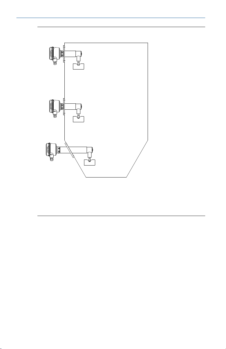
Figure 2-7: Rosemount 2501K Mounting Examples
A. Horizontal mounting for full-silo (overfill) detection
B. Horizontal mounting for demand detection
C. Horizontal mounting for empty-silo detection
A protective angle is recommended depending on the load.
18 Quick Start Guide
Page 19
A
B
C
D
October 2019 Quick Start Guide
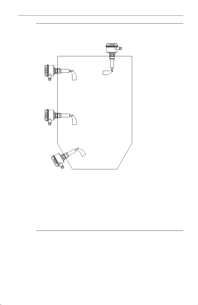
Figure 2-8: Rosemount 2501J Mounting Examples
A. Vertical or angled mounting, at the top of silo, for full-silo (overfill)
detection
B. Horizontal mounting, at the top of silo, for full-silo (overfill) detection
C. Horizontal mounting for demand detection
D. Angled mounting, at the bottom of silo, for empty-silo detection
E. A protective angle is recommended depending on the load
The boot-shaped vane (paddle) is recommended for horizontal mountings
because it aligns to the movement of the solids material. See Mechanical
load and Sensitivity to check that the paddle meets the application limits.
Quick Start Guide 19
Page 20

Quick Start Guide October 2019
3 Electrical installation
3.1 Safety messages
WARNING
Failure to follow safe installation and servicing guidelines could result in
death or serious injury.
• Ensure the level switch is installed by qualified personnel and in
accordance with applicable code of practice.
• Use the level switch only as specified in this manual. Failure to do so may
impair the protection provided by the level switch.
Explosions could result in death or serious injury.
• The level switch must only be installed and operated in non-hazardous
(ordinary) locations.
Electrical shock could cause death or serious injury.
• Avoid contact with the leads and terminals. High voltage that may be
present on leads can cause electrical shock.
• Ensure the power to the level switch is off, and the lines to any other
external power source are disconnected or not powered while wiring the
level switch.
• Ensure the wiring is suitable for the electrical current and the insulation is
suitable for the voltage, temperature, and environment.
3.2
Wiring considerations
3.2.1 Handling
In cases of improper handling or handling malpractice, the electrical safety
of the device cannot be guaranteed.
3.2.2 Installation regulations
Local regulations or VDE 0100 (Regulations of German Electrotechnical
Engineers) must be observed.
When using 24 V supply voltage, an approved power supply with reinforced
insulation to mains is required.
3.2.3 Fuse
Use a fuse as stated in the connection diagrams.
For details, see Wiring the level switch.
20 Quick Start Guide
Page 21

October 2019 Quick Start Guide
3.2.4 Residual Current Circuit Breaker (RCCB) protection
In case of a defect, the distribution voltage must automatically be cut-off by
an RCCB protection switch to protect against indirect contact with
dangerous voltages.
3.2.5 Power supply
Power supply switch
A voltage disconnection switch must be provided near the device.
Supply voltage
Compare the supply voltage applied with the specifications given on the
electronic module and nameplate before switching on the device.
3.2.6 Wiring
Field wiring cables
The diameter has to match the clamping range of the used cable gland.
The cross-section has to match the clamping range of the connection
terminals and the maximum current must be considered.
All field wiring must have insulation suitable for at least 250 Vac.
The temperature rating must be at least 194 °F (90 °C).
Use a shielded cable when there are electrical interferences present that are
higher than stated in the EMC standards. Otherwise, an unshielded
instrumentation cable can be used.
Wiring diagram
The electrical connections are made in accordance with the wiring diagram.
Guiding the cables in the terminal box
The field wiring cables must be cut to a length to be able to properly fit them
into the terminal box.
3.2.7 Cable glands
The screwed cable gland and stopping plug must have the following
specifications:
• Ingress protection IP66
• Temperature range from -40 °C to +70 °C
• Pull relief
Quick Start Guide 21
Page 22
7
6 5 1 2
A
A
B
C
Quick Start Guide October 2019
Ensure the screwed cable gland safely seals the cable and is tight enough to
prevent water ingress. Unused conduit or cable entries must be sealed with a
stopping (blanking) plug.
A strain relief must be provided for the field wiring cables when the device is
installed with the factory-provided cable glands.
3.2.8 Conduit system
When a threaded conduit system is used instead of a cable gland, the
regulations of the country must be observed. The conduit must have a ½-in.
NPT tapered thread to match a NPT threaded conduit entry of the level
switch and comply with ANSI B 1.20.1. Unused conduit entries must be
closed tightly with a metal stopping (blanking) plug.
3.2.9 Micro-switch protection
Provide protection for micro-switch contacts to protect the device against
inductive load surges.
3.2.10 Static charging
The Rosemount 2501 must be grounded to avoid a static electrical build-up.
This is particularly important for applications with pneumatic conveying and
non-metallic containers.
3.2.11 Commissioning
Commissioning must be performed with closed lid.
3.3
Wiring the level switch
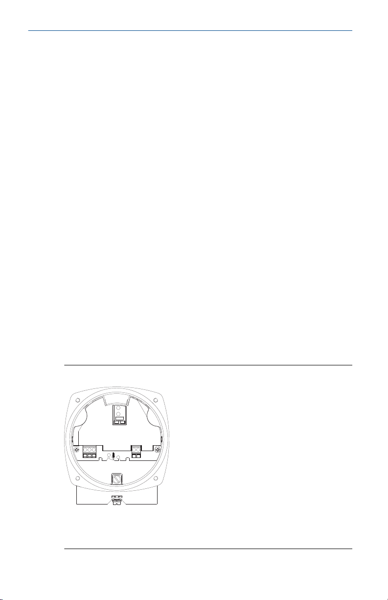
Wiring connections are done directly on the PCB.
Figure 3-1: PCB Connections
A. Connection terminals for power supply and signal outputs
B. The motor is internally connected to the housing (grounded)
22 Quick Start Guide
C. Protective Earth (PE) terminal
Page 23
56
7
21
L N+PE
-
B
A
October 2019 Quick Start Guide
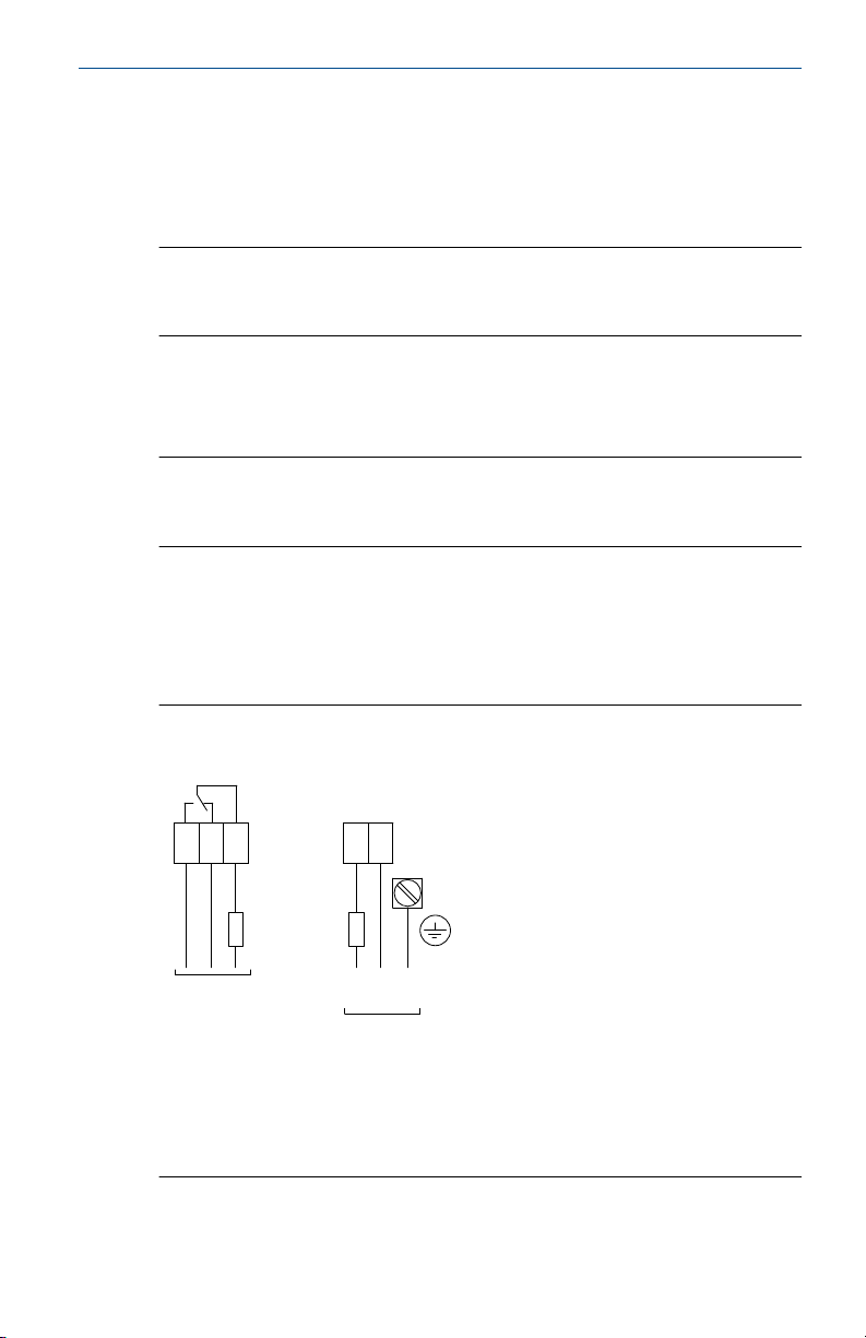
Wiring the ac and dc voltage versions
Power supply (ac version):
• 24, 48, 115 , or 230 Vac (50/60 Hz), maximum of 4 VA
• External fuse: maximum 10 A, fast or slow, HBC, 250 Vac
Note
The supply voltage is selected when ordering the level switch.
All voltages are ±10% (EN 61010).
Power supply (dc version):
• 24 Vdc ±15%, maximum of 2.5 W
• External fuse: not required
Note
The supply voltage is selected when ordering the level switch.
The voltage variance of ±15% includes the ±10% of EN 61010.
Signal output (ac and dc versions):
• Micro-switched, SPDT relay contacts
• Maximum 250 Vac, 5 A, non-inductive
• Maximum 30 Vdc, 4 A, non-inductive
Figure 3-2: Terminal Connections (Ac and Dc Voltage Versions)
A. Signal output connections
B. Power supply connections
Maximum wire size is 4 mm2 (AWG12).
Quick Start Guide 23
Page 24
67108 9 45
A B
21
L
+ -
N PE
C
Quick Start Guide October 2019
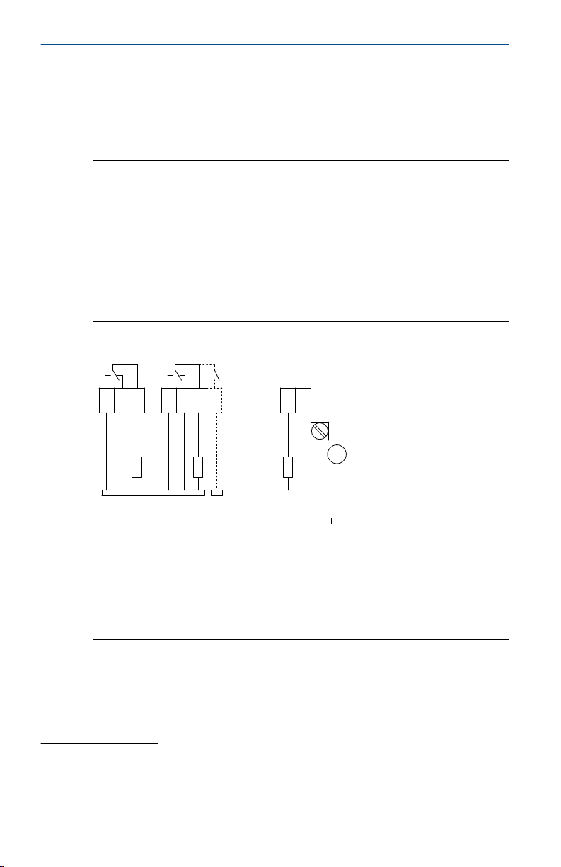
Wiring the universal voltage version
Power supply (universal voltage version):
• 24 Vdc ±15%, maximum 4 W
• 22 to 230 Vac (50/60 Hz) ±10%, maximum 10 VA
Note
The voltage variances of ±10% and ±15% include the ±10% of EN 61010.
Signal and alarm outputs (universal voltage version):
• DPDT relay contacts
• Maximum 250 Vac, 5 A, non-inductive
• Maximum 30 Vdc, 4 A, non-inductive
• External fuse: maximum 10 A, fast or slow, HBC, 250 V
Figure 3-3: Wiring Connections (Universal Voltage Version)
A. Signal output connections
B. Alarm output connections
(2)
C. Power supply connections
Maximum wire size is 4 mm2 (AWG12).
Grounding
The PE terminal of the level switch must be connected to an earth
(grounding point) to avoid static electrical discharges. This is particularly
important for applications with pneumatic conveyors.
(2) Available only when the Fail Safe Alarm (rotation control) option is selected at the
time of ordering.
The relay contact is open when de-energized.
24 Quick Start Guide
Page 25
3
A
B
61020
30
600
1
236
10
200
B
A
C
October 2019 Quick Start Guide
4 Configuration
4.1 Signal output delay
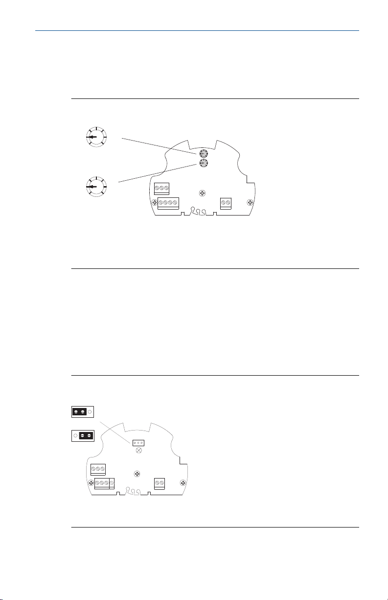
Figure 4-1: Delay Timers for Signal Output Change
A. Delay timer in seconds - for the switchover from a covered-to-uncovered
paddle state. Factory default is 3 seconds.
B. Delay timer in seconds - for the switchover from an uncovered-to-covered
paddle state. Factory default is 1 second.
4.2 Jumper Settings for Fail Safe High or Low
Use the FSH setting when the level switch is to be applied as a full-silo
detector. A power failure or line break is regarded as a full-silo signal (as
protection against overfilling).
Use the FSL setting when the level switch is to be applied as an empty-silo
detector. A power failure or line break is regarded as empty-silo signal (as
protection against running dry).
Figure 4-2: Jumper Settings for FSH or FSL
Quick Start Guide 25
A. Jumper setting for enabling FSL (factory default)
B. Jumper setting for enabling FSH
Page 26
12
567
A
B
C
D
Quick Start Guide October 2019
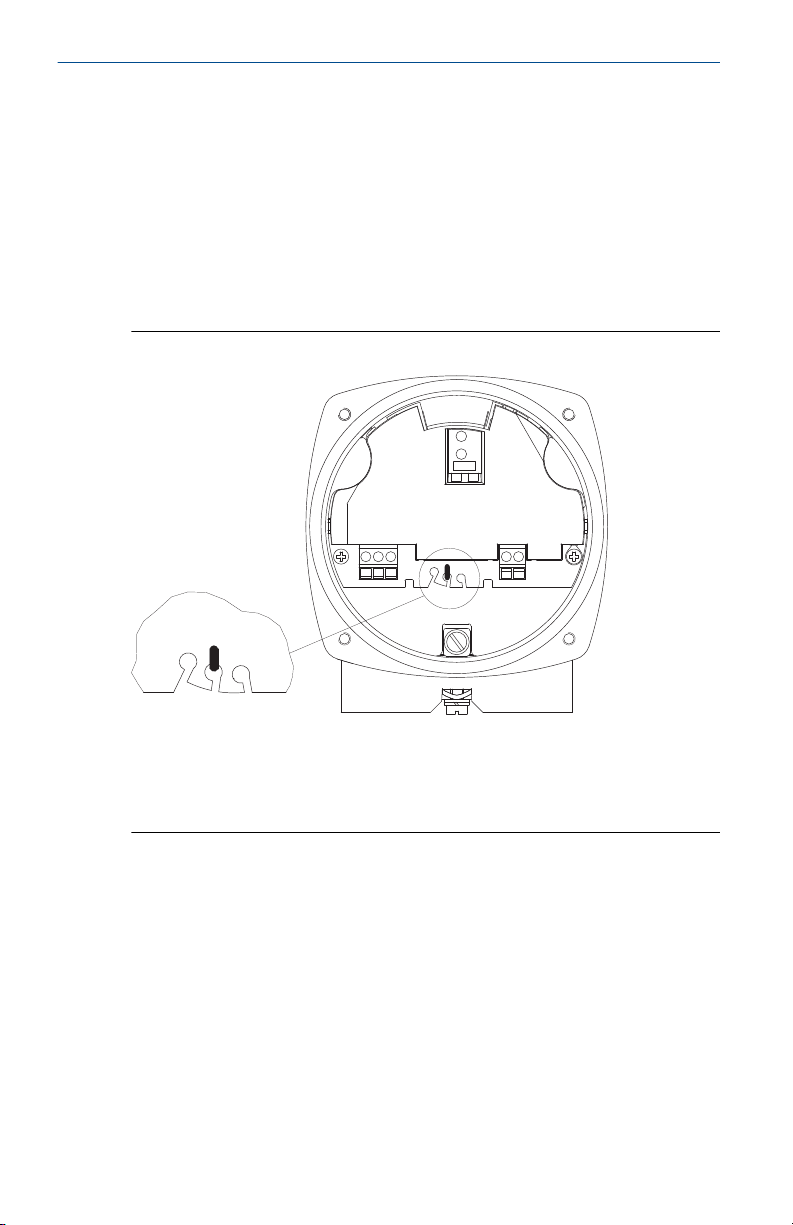
4.3 Adjustment of the spring
The spring is adjustable in three positions. It should be changed only if
necessary.
• Fine for light material
• Medium for nearly every material (factory setting)
• Coarse for very sticky material
The spring can be changed using small pliers.
Figure 4-3: Adjustment of the Spring
A. Spring
B. Fine
C. Medium
D. Coarse
26 Quick Start Guide
Page 27
October 2019 Quick Start Guide
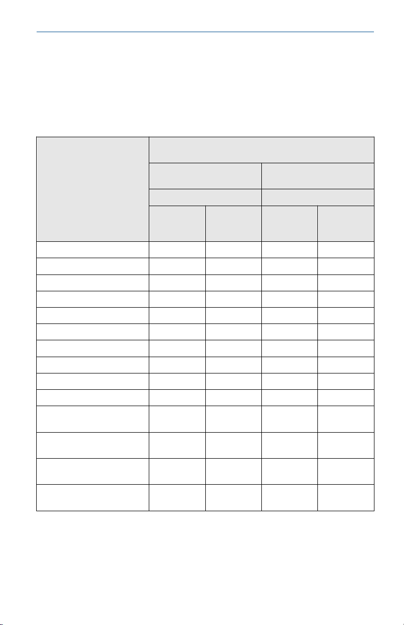
4.4 Sensitivity
Table 4-1 shows approximate values for the minimum densities, at which a
normal function should be possible. It is a guideline only for loose, noncompacted material. During a filling operation, the density of bulk material
can change (e.g. for fluidized material).
Table 4-1: Minimum Density Requirements and Sensitivity Settings
Paddle Minimum density in g/l = kg/m3 (lb/ft3)
Boot-shaped vane 40 x 98 200 (12) 300 (18) 100 (60) 150 (9)
Boot-shaped vane 35 x 106 200 (12) 300 (18) 100 (60) 150 (9)
Boot-shaped vane 28 x 98 300 (18) 500 (30) 150 (9) 200 (12)
Boot-shaped 26 x 77 350 (21) 560 (33) 200 (12) 250 (15)
Vane 50 x 98 300 (18) 500 (30) 150 (9) 250 (15)
Vane 50 x 150 80 (4.8) 120 (7.2) 40 (2.4) 60 (3.6)
Vane 50 x 250 30 (1.8) 50 (3) 15 (0.9) 25 (1.5)
Vane 98 x 98 100 (60) 150 (9) 50 (3) 75 (4.5)
Vane 98 x 150 30 (1.8) 50 (3) 15 (0.9) 25 (15)
Vane 98 x 250 20 (1.2) 30 (1.8) 15 (0.9) 15 (0.9)
Hinged vane 98 x 200 b=37
double-sided
Hinged vane 98 x 200 b=28
double-sided
Hinged vane 98 x 100 b=37
single-sided
Hinged vane 98 x 100 b=28
single-sided
guarantee)
Bulk material completely
covering the vane
Spring adjustment Spring adjustment
Fine Medium
(factory
setting)
70 (4.2) 100 (60) 35 (2.16) 50 (3)
100 (60) 150 (9) 50 (3) 75 (4.5)
200 (12) 300 (18) 100 (60) 150 (9)
300 (18) 500 (30) 150 (9) 250 (15)
Bulk material covering the
vane up to 3.93 in. (100 mm)
Fine Medium
(1)
(without
(factory
setting)
(1) For versions with the Heating of housing option, the above-mentioned data must be
multiplied by 1.5.
Quick Start Guide 27
Page 28
765
7 6 5
A
B
Quick Start Guide October 2019
5 Operation
5.1 Overview of the outputs
For an overview of signal and alarm output for the different electronic
versions, see Electronics.
5.2 Signal outputs
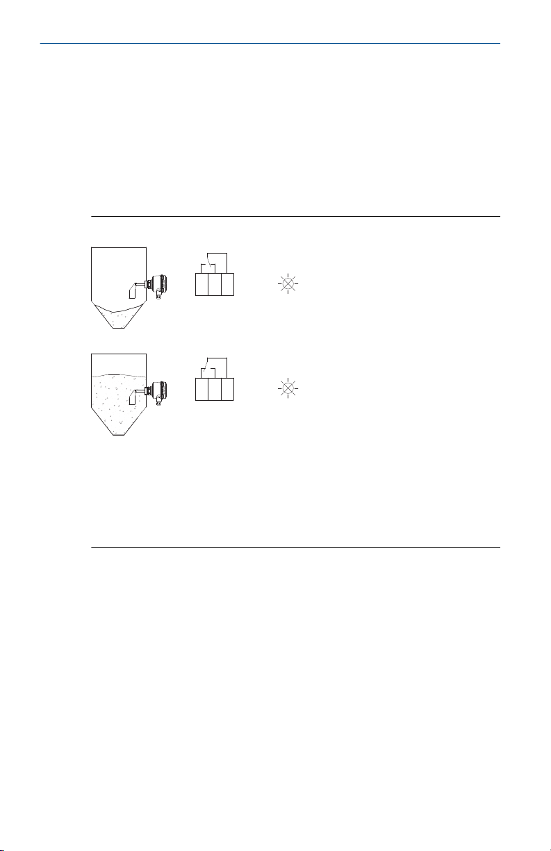
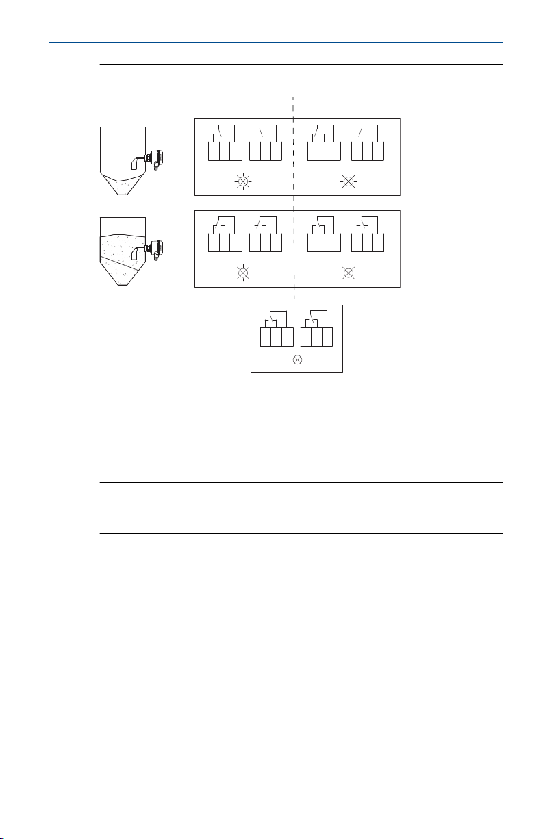
Figure 5-1: Switching Logic (Ac and Dc Versions)
A. Green
B. Red
• The dc-voltage version has a LED that changes color to indicate if the
paddle is covered or uncovered by solids material.
• The ac-voltage version does not have a LED.
28 Quick Start Guide
Page 29
8
9
10
8
9
10
7
6
5
7
6
5
8
9
10
7
6
5
8
9
10
8
9
10
7
6
5
7
6
5
A B
C
D
D
C
E
October 2019 Quick Start Guide
Figure 5-2: Switching Logic (Universal Voltage Version)
A. FSL (Fail Safe Low)
B. FSH (Fail Safe High)
C. Yellow
D. Green
E. Power failure
Note
See Jumper Settings for Fail Safe High or Low for details on how to select an
FSH or FSL alarm output.
Quick Start Guide 29
Page 30
7
A B
C
6 5 4 7 6 5 4
7 6 5 4
Quick Start Guide October 2019
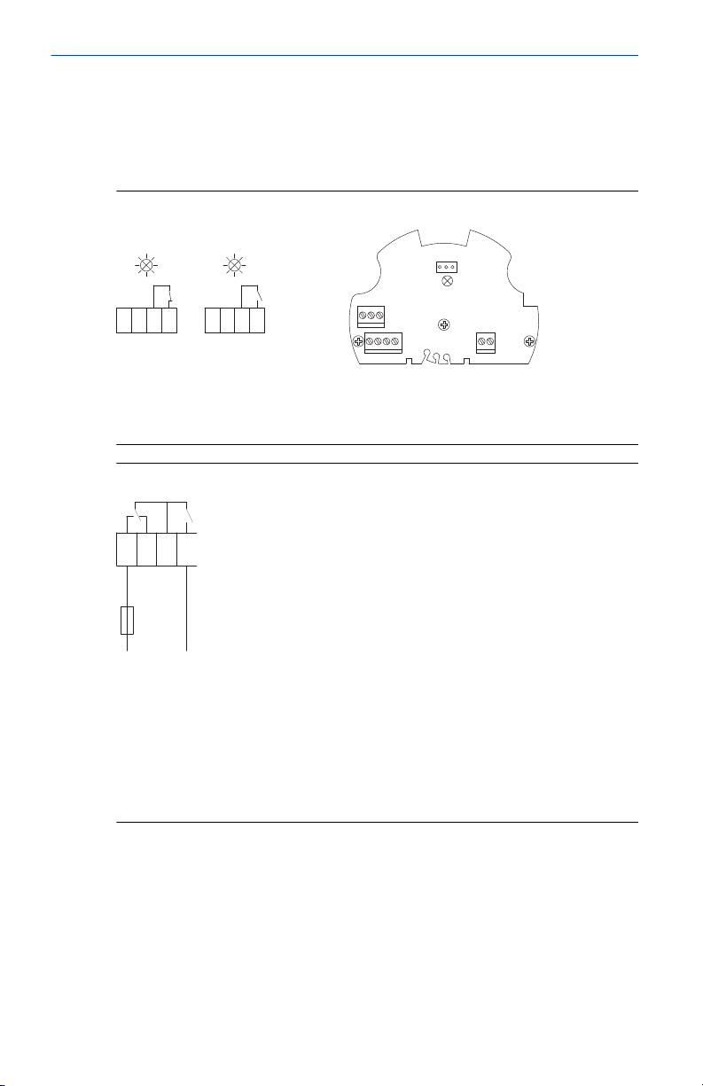
5.3 Alarm output (Fail Safe High or Low)
If the paddle of the level switch is not covered, the rotating paddle shaft
triggers pulses at 20-second intervals. In the event of a fault, the pulses are
stopped and the alarm relay de-energizes after 30 seconds.
Figure 5-3: Switching Logic (Universal Voltage Version)
A. Yellow or green, i.e. no fault. See Figure 5-2.
B. Red, i.e. fault
C. LED location on PCB
Figure 5-4: Connection Example
When a Rosemount 2501 is used in a full-silo detection application with
maximum safety, the output signal can indicate:
• Full-silo signal
• Failure of supply voltage
• Incorrect wiring
• The level switch has developed a fault
30 Quick Start Guide
Page 31

October 2019 Quick Start Guide
6 Maintenance
6.1 Opening the lid (cover)
Before opening the lid for maintenance reasons, consider the following:
• Do not remove the lid while circuits are live.
• Ensure that no dust deposits or airborne dusts are present.
• Ensure that rain does not enter the housing.
6.2 Regular checks for safety
To ensure robust safety in hazardous locations and with electrical safety, the
following items must be regularly checked depending on the application:
• Mechanical damage or corrosion of the field wiring cables or any other
components (housing side and sensor side).
• Tight sealing of the process connection, cable glands, and enclosure lid.
• Properly connected external PE cable (if present).
6.3 Cleaning
If cleaning is required by the application, following must be observed:
• Cleaning agent must comply with the materials of the unit (chemical
resistance). Mainly the shaft sealing, lid sealing, cable gland and the
surface of the unit must be considered.
The cleaning process must be done in a way, that:
• The cleaning agent cannot enter into the unit through the shaft sealing,
lid sealing or cable gland.
• No mechanical damage of the shaft sealing, lid sealing, cable gland or
other parts can happen.
6.4
Quick Start Guide 31
Function test
A frequent function test may be required depending on the application.
Observe all relevant safety precautions related to work safety (e.g. electrical
safety, process pressure, etc).
This test does not prove if the level switch is sensitive enough to measure
the material of the application.
Function tests are done by stopping the rotating paddle with appropriate
means and monitoring if a correct change of the signal output from
uncovered to covered happens.
Page 32

Quick Start Guide October 2019
6.5 Production date
The production year is shown on the nameplate.
6.6 Spare parts
Refer to the Rosemount 2501 Product Data Sheet for all spare parts.
32 Quick Start Guide
Page 33
October 2019 Quick Start Guide
7 Product certifications
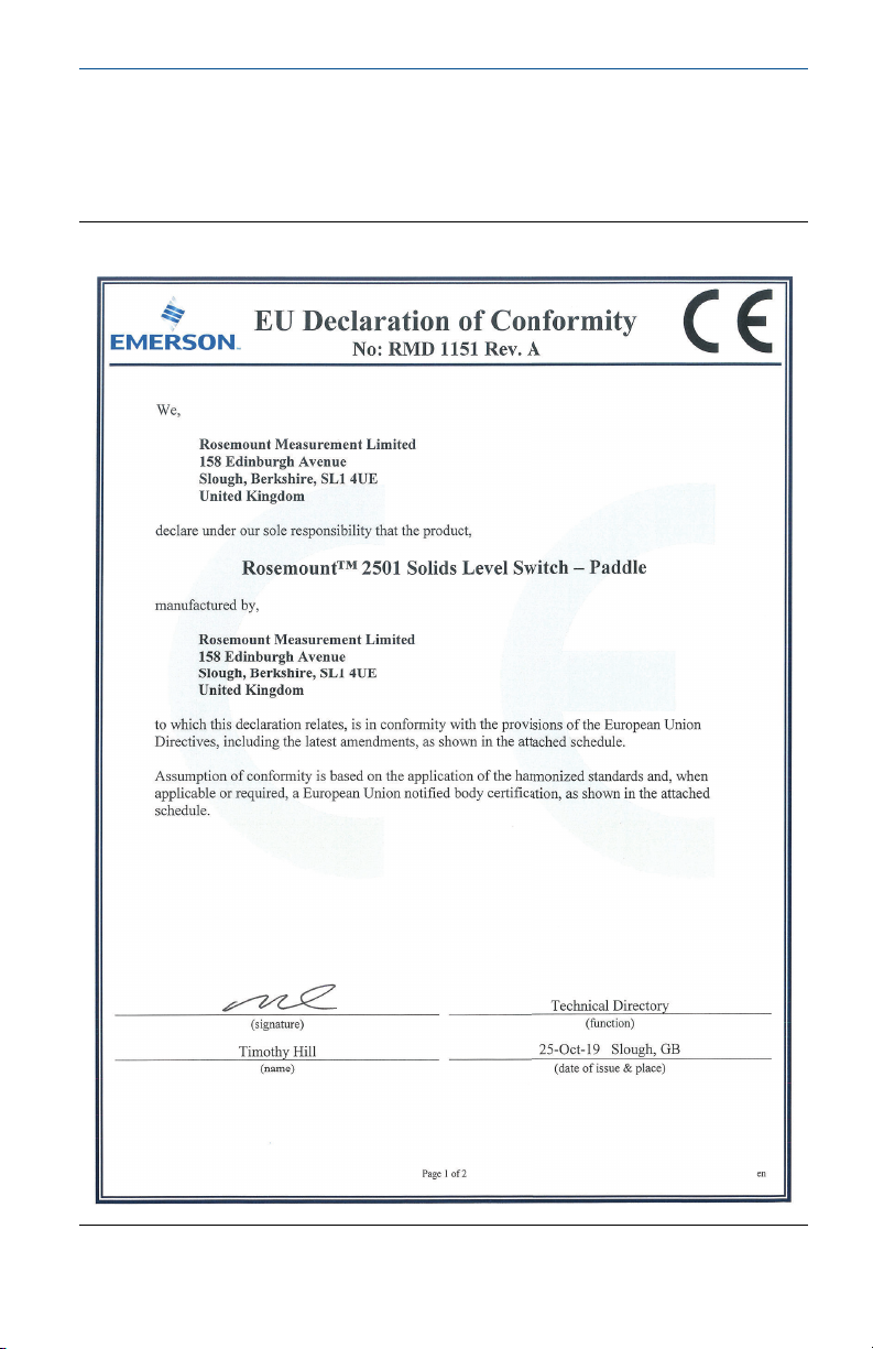
7.1 EU Declaration of Conformity
Figure 7-1: EU Declaration of Conformity (Page 1)
Quick Start Guide 33
Page 34
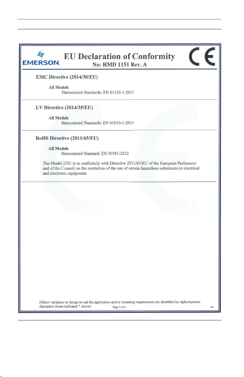
Quick Start Guide October 2019
Figure 7-2: EU Declaration of Conformity (Page 2)
34 Quick Start Guide
Page 35
含含有有
China RoHS
管管控控物物质质超超过过最最大大浓浓度度限限值值的的部部件件型型号号列列表表
Rosemount 2501
List of Rosemount 2501 Parts with China RoHS Concent ration above MCVs
部部件件 名名称称
Part Name
有有害害 物物质质 / Hazardous Substances
铅铅
Lead
(Pb)
汞汞
Mercury
(Hg)
镉镉
Cadmium
(Cd)
六六价价 铬铬
Hexavalent
Chromium
(Cr +6)
多多溴溴 联联苯苯
Polybrominated
biphenyls
(PBB)
多多溴溴 联联苯苯醚醚
Polybrominated
diphenyl ethers
(PBDE)
电子组件
Electronics
Assembly
OOO
O
壳体组件
Housing
Assembly
OOOOO
XXOOOOO
本表格系依据
SJ/T11364
的规定而制作.
This table is proposed in accordance with the provision of SJ/T11364.
O:
意为该部件的所有均质材料中该有害物质的含量均低于
GB/T 26572
所规定的限量要求.
O: Indicate that said hazardous substance in all of the homogeneous materials for this part is below the limit requirement of
GB/T 26572.
X:
意为在该部件所使用的所有均质材料里,至少有一类均质材料中该有害物质的含量高于
GB/T 26572
所规定的限量要求.
X: Indicate that said hazardous substance contained in at least one of the homogeneous materials used for this part is above
the limit requirement of GB/T 26572.
X
X X
Process Connection /
Extension
Measuring Vane
过程连接/扩展部件
测量叶片
OO O O O O
October 2019 Quick Start Guide
7.2 European Union directive information
The most recent revision of the EU Declaration of Conformity can be found
at Emerson.com/Rosemount.
7.3 China RoHS
Quick Start Guide 35
Page 36

*00825-0100-2501*
00825-0100-2501, Rev. AA
Quick Start Guide
October 2019
Global Headquarters
Emerson Automation Solutions
6021 Innovation Blvd.
Shakopee, MN 55379, USA
+1 800 999 9307 or +1 952 906 8888
+1 952 204 8889
[email protected]
Latin America Regional Office
Emerson Automation Solutions
1300 Concord Terrace, Suite 400
Sunrise, FL 33323, USA
+1 954 846 5030
+1 954 846 5121
[email protected]
Asia Pacific Regional Office
Emerson Automation Solutions
1 Pandan Crescent
Singapore 128461
+65 6777 8211
+65 6777 0947
[email protected]
North America Regional Office
Emerson Automation Solutions
8200 Market Blvd.
Chanhassen, MN 55317, USA
+1 800 999 9307 or +1 952 906 8888
+1 952 204 8889
[email protected]
Europe Regional Office
Emerson Automation Solutions Europe
GmbH
Neuhofstrasse 19a P.O. Box 1046
CH 6340 Baar
Switzerland
+41 (0) 41 768 6111
+41 (0) 41 768 6300
[email protected]
Middle East and Africa Regional Office
Emerson Automation Solutions
Emerson FZE P.O. Box 17033
Jebel Ali Free Zone - South 2
Dubai, United Arab Emirates
+971 4 8118100
+971 4 8865465
[email protected]
Linkedin.com/company/Emerson-
Automation-Solutions
Twitter.com/Rosemount_News
Facebook.com/Rosemount
Youtube.com/user/
RosemountMeasurement
©
2019 Emerson. All rights reserved.
Emerson Terms and Conditions of Sale are
available upon request. The Emerson logo is a
trademark and service mark of Emerson Electric
Co. Rosemount is a mark of one of the Emerson
family of companies. All other marks are the
property of their respective owners.
 Loading...