


Version 1.5 and later
Owner’s Manual (this document)
Read this rst. It explains the basic things you need
to know in order to use the V-1SDI.
PDF Manual (download from the Web)
5 Remote Control Guide
This manual covers remote control of the V-1SDI via
MIDI, menu items, and RS-232 commands.
Before using the V-1SDI, ensure that its system program is at the most recent version. For information on available
upgrades for the system program, see the Roland website (http://proav.roland.com). You can check the system
program version by pressing and holding the [SETUP] button g “VERSION” at the SETUP menu (page 16/16).
To obtain the PDF manual
1. Enter the following URL in your computer.
http://proav.roland.com
I
2. Go to the V-1SDI product page and click
the “Support” tab.
Copyright © 2017 ROLAND CORPORATION
Contents
USING THE UNIT SAFELY . . . . . . . . . . . . . . . . . . . . . 3
IMPORTANT NOTES . . . . . . . . . . . . . . . . . . . . . . . . . . 5
Panel Descriptions . . . . . . . . . . . . . . . . . . . . . . . . . . 6
Top Panel/Front Panel . . . . . . . . . . . . . . . . . . . . . . . 6
Rear Panel (Connecting Your Equipment) . . . . . . . 8
Side Panel (Connecting Your Equipment) . . . . . . . 10
Basic Operation . . . . . . . . . . . . . . . . . . . . . . . . . . . . . 11
Turning the Power On and O . . . . . . . . . . . . . . . . 11
Turning O the Power Automatically
Using the Menus . . . . . . . . . . . . . . . . . . . . . . . . . . . . 12
Saving/Recalling Settings (Memory) . . . . . . . . . . . 13
(Auto O)
. . . . . . 11
Video Input/Output Settings . . . . . . . . . . . . . . . . . 14
Setting the Video Input/Output Format . . . . . . . . 14
Adjusting Output Video . . . . . . . . . . . . . . . . . . . . . . 15
Adjusting HDMI Input Video on Channel 4 . . . . . . 15
Assigning a Video Source to Channel 3 . . . . . . . . . 16
Switching the View Mode of Preview Output . . . . 16
Inputting Copyright-protected (HDCP) Video . . . 17
Video Operations . . . . . . . . . . . . . . . . . . . . . . . . . . . . 18
Switching the Video . . . . . . . . . . . . . . . . . . . . . . . . . 18
About the Operation Mode for Video
Transitions
Switching Using the PGM/PST Mode . . . . . . . . . 18
Switching in the A/B Mode . . . . . . . . . . . . . . . . . 19
Switching Automatically (Auto Scan) . . . . . . . . . 20
Freezing Input Video (Freeze) . . . . . . . . . . . . . . . . . 20
Applying a Fade to the Main Output Video
Capturing a Still Image from Input Video . . . . . . . 21
. . . . . . . . . . . . . . . . . . . . . . . . . . . . . . . 18
(Output Fade)
. . . 21
Video Composition Operations . . . . . . . . . . . . . . . 22
Selecting a Composition Type . . . . . . . . . . . . . . . . 22
Compositing Four Video Pictures
Compositing Using Picture-in-Picture . . . . . . . . . . 23
Compositing Using Split . . . . . . . . . . . . . . . . . . . . . 24
Compositing Using DSK . . . . . . . . . . . . . . . . . . . . . . 24
into One Screen
. . . . . 22
Audio Operations . . . . . . . . . . . . . . . . . . . . . . . . . . . 26
Adjusting the Volume Level . . . . . . . . . . . . . . . . . . 26
Applying Eects to Audio . . . . . . . . . . . . . . . . . . . . 27
Applying Eects to Input Audio . . . . . . . . . . . . . 27
Applying Eects to Output Audio . . . . . . . . . . . 28
Interlinking Audio Output to Video Switching
(Audio Follow)
. . 29
Other Features . . . . . . . . . . . . . . . . . . . . . . . . . . . . . . 30
Returning Settings to the Factory-
Preventing Unintended Operation (Panel Lock). . 30
Operating the V-1SDI by Remote Control . . . . . . . 31
default State (Factory Reset)
. . . . . 30
Appendices . . . . . . . . . . . . . . . . . . . . . . . . . . . . . . . . . 32
Troubleshooting . . . . . . . . . . . . . . . . . . . . . . . . . . . . 32
Transition Eects List . . . . . . . . . . . . . . . . . . . . . . . . 33
Block Diagram . . . . . . . . . . . . . . . . . . . . . . . . . . . . . . 34
Main Specications . . . . . . . . . . . . . . . . . . . . . . . . . 36
Dimensions . . . . . . . . . . . . . . . . . . . . . . . . . . . . . . . . 37
Before using this unit, carefully read “USING THE UNIT
SAFELY” (p. 3) and “IMPORTANT NOTES” (p. 5).
After reading, keep the document(s) including those
sections where it will be available for immediate reference.
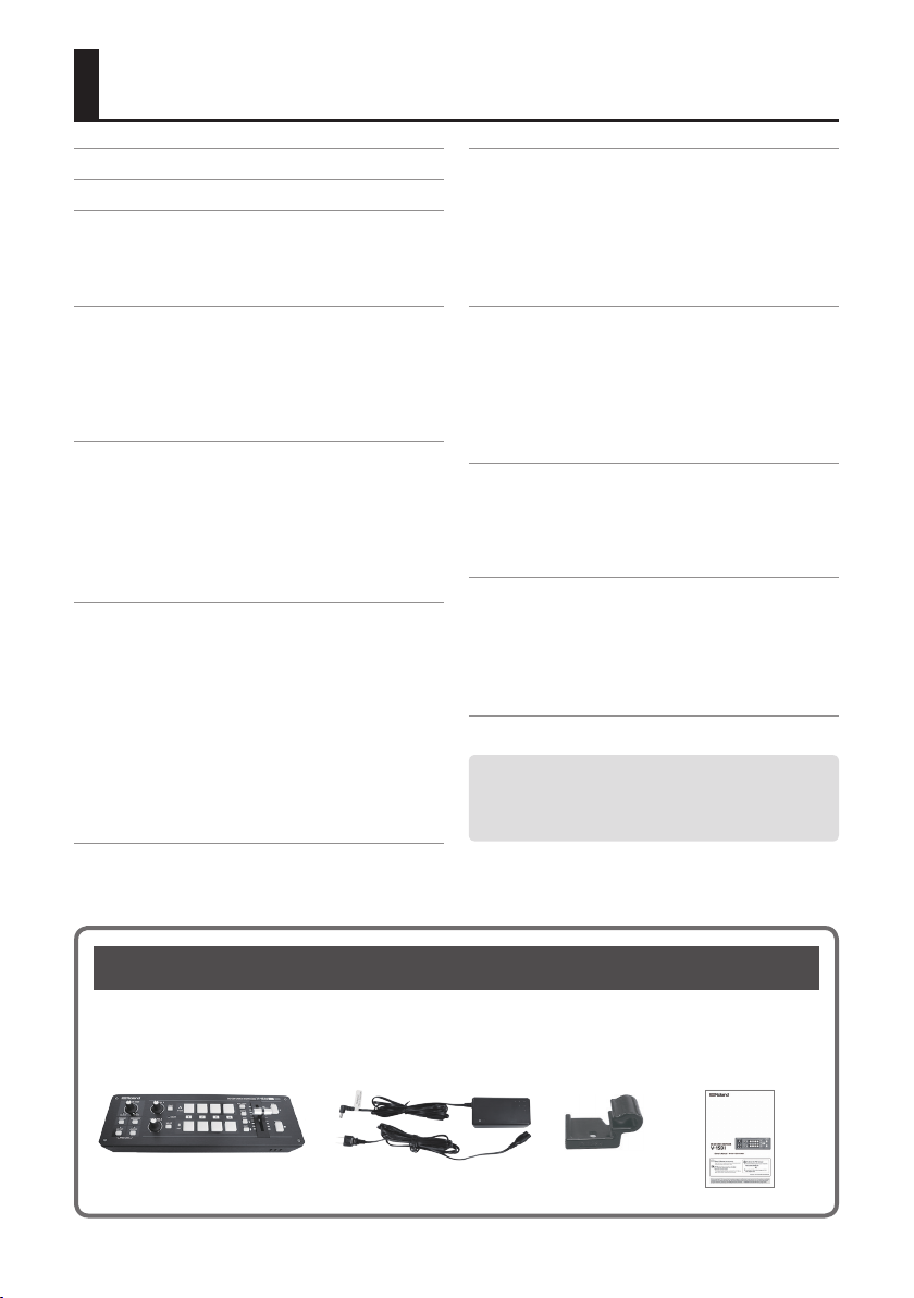
Checking the Included Items
The V-1SDI includes the following items. Please take a moment to conrm that all of these items have
been included with the V-1SDI. If you nd that any item is missing, contact the nearest authorized Roland
distributor in your country.
The Unit AC Adaptor/Power Cord Cord Hook Owner’s Manual
* The shape of the power cord’s plug
varies depending on the country.
2
USING THE UNIT SAFELY
About WARNING and CAUTION Notices
ALWAYS OBSERVE THE FOLLOWING
About the Symbols
Used for instructions intended to alert
the user to the risk of death or severe
injury should the unit be used
improperly.
Used for instructions intended to alert
the user to the risk of injury or material
damage should the unit be used
improperly.
* Material damage refers to damage or
other adverse eects caused with
respect to the home and all its
furnishings, as well to domestic
animals or pets.
The symb ol alerts the user to important
instruc tions or warnings.The sp ecic meaning of the
symbol is determined by the design contained within
the triangle. In the case of th e symbol at left, it is used
for general cautions, warnings, or alerts to danger.
The symbol alerts the user to items that must never
be carried out (are forbidden). The specic thing that
must not be done is indicated by the design contained
within the circle. In the case of the symbol at left, it
means that the unit must never be disassembled.
The symbol alerts the user to things that must be
carried out. The specic thing that must be done is
indicated by the design contained within the circle. In
the case of the symbol at left, it means that the
power-cord plug must be unplugged from the outlet.
WARNING
To completely turn o power to the unit, pull out the plug
from the outlet
Even with the power switch turned o, this
unit is not completely separated from its main
source of power. When the power needs to
be completely turned o, turn o the power
switch on the unit, then pull out the plug from the
outlet. For this reason, the outlet into which you choose
to connect the power cord’s plug should be one that is
within easy reach and readily accessible.
Concerning the Auto O function
On this unit, the power is automatically turned
o after a predetermined amount of time has
passed since an operation was performed
(Auto O function). If you do not want the
power to be turned o automatically, disengage the
Auto O function (p. 11).
Do not disassemble or modify by yourself
Do not carry out anything unless you are
instructed to do so in the owner’s manual.
Otherwise, you risk causing malfunction.
Do not repair or replace parts by yourself
Refer all servicing to your retailer, the nearest
Roland Service Center, or an authorized Roland
distributor, as listed on the “Information.”
Do not place in an unstable location
Otherwise, you risk injury as the result of the
unit toppling over or dropping down.
WARNING
Do not use or store in the following types of locations
• Subject to temperature extremes (e.g.,
direct sunlight in an enclosed vehicle, near
a heating duct, on top of heat-generating
equipment); or are
• Damp (e.g., baths, washrooms, on wet
oors); or are
• Exposed to steam or smoke; or are
• Subject to salt exposure; or are
• Exposed to rain; or are
• Dusty or sandy; or are
• Subject to high levels of vibration and shakiness; or are
• Placed in a poorly ventilated location.
Use only the supplied AC adaptor and the correct voltage
Be sure to use only the AC adaptor supplied
with the unit. Also, make sure the line voltage
at the installation matches the input voltage
specied on the AC adaptor’s body. Other AC
adaptors may use a dierent polarity, or be designed for
a dierent voltage, so their use could result in damage,
malfunction, or electric shock.
Use only the supplied power cord
Use only the attached power cord. Also, the
supplied power cord must not be used with
any other device.
Do not bend the power cord or place heavy
objects on it
Otherwise, re or electric shock may result.
Avoid extended use at high volume
Use of the unit at high volume for extended
periods of time may cause hearing loss. If you
ever experience any hearing loss or ringing in
the ears, you should immediately stop using
the unit and consult a specialized physician.
3
USING THE UNIT SAFELY
WARNING
Do not allow foreign objects or liquids to enter
unit; never place containers with liquid on unit
Do not place containers containing liquid (e.g.,
ower vases) on this product. Never allow
foreign objects (e.g., ammable objects, coins,
wires) or liquids (e.g., water or juice) to enter
this product. Doing so may cause short circuits,
faulty operation, or other malfunctions.
Turn o the unit if an abnormality or malfunction occurs
Immediately turn the unit o, remove the AC
adaptor from the outlet, and request servicing
by your retailer, the nearest Roland Service
Center, or an authorized Roland distributor, as
listed on the “Information” when:
• The AC adaptor or the power cord has been damaged; or
• If smoke or unusual odor occurs; or
• Objects have fallen into, or liquid has been spilled
onto the unit; or
• The unit has been exposed to rain (or otherwise has
become wet); or
• The unit does not appear to operate normally or
exhibits a marked change in performance.
Be cautious to protect children from injury
Always make sure that an adult is on hand to
provide supervision and guidance when using
the unit in places where children are present,
or when a child will be using the unit.
Do not drop or subject to strong impact
Otherwise, you risk causing damage or
malfunction.
Do not share an outlet with an unreasonable
number of other devices
Otherwise, you risk overheating or re.
Do not use overseas
Before using the unit in overseas, consult with
your retailer, the nearest Roland Service Center,
or an authorized Roland distributor, as listed on
the “Information.”
CAUTION
When disconnecting the power cord, grasp it by the plug
To prevent conductor damage, always grasp
the power cord by its plug when disconnecting
it from this unit or from a power outlet.
Periodically clean the power plug
An accumulation of dust or foreign objects
between the power plug and the power outlet
can lead to re or electric shock.
At regular intervals, be sure to pull out the
power plug, and using a dry cloth, wipe away any dust or
foreign objects that may have accumulated.
4
CAUTION
Disconnect the power plug whenever the unit will not be
used for an extended period of time
Fire may result in the unlikely event that a
breakdown occurs.
Route all power cords and cables in such a way as to prevent
them from getting entangled
Injury could result if someone were to trip on a
cable and cause the unit to fall or topple.
Avoid climbing on top of the unit, or placing heavy objects
on it
Otherwise, you risk injury as the result of the
unit toppling over or dropping down.
Never connect/disconnect a power plug if your hands are
wet
Otherwise, you could receive an electric shock.
Disconnect all cords/cables before moving the unit
Before moving the unit, disconnect the power
plug from the outlet, and pull out all cords
from external devices.
Before cleaning the unit, disconnect the power plug from
the outlet
If the power plug is not removed from the
outlet, you risk receiving an electric shock.
Whenever there is a threat of lightning, disconnect the
power plug from the outlet
If the power plug is not removed from the
outlet, you risk receiving an electric shock.
Keep small items out of the reach of children
To prevent accidental ingestion of the parts
listed below, always keep them out of the
reach of small children.
• Included Parts: Cord Hook (p. 2)
• Removable Parts: Screw (p. 9, 10)
Handle the ground terminal carefully
If you remove the screw from the ground
terminal, be sure to replace it; don’t leave it
lying around where it could accidently be
swallowed by small children. When refastening
the screw, make that it is rmly fastened, so it won’t
come loose.

IMPORTANT NOTES
Power Supply
• Do not connect this unit to same electrical outlet that is
being used by an electrical appliance that is controlled
by an inverter or a motor (such as a refrigerator,
washing machine, microwave oven, or air conditioner).
Depending on the way in which the electrical appliance
is used, power supply noise may cause this unit to
malfunction or may produce audible noise. If it is not
practical to use a separate electrical outlet, connect
a power supply noise lter between this unit and the
electrical outlet.
• The AC adaptor will begin to generate heat after long
hours of consecutive use. This is normal, and is not a
cause for concern.
Placement
• Using the unit near power ampliers (or other
equipment containing large power transformers) may
induce hum. To alleviate the problem, change the
orientation of this unit; or move it farther away from
the source of interference.
• This unit may interfere with radio and television
reception. Do not use this unit in the vicinity of such
receivers.
• Noise may be produced if wireless communications
devices, such as cell phones, are operated in the vicinity
of this unit. Such noise could occur when receiving
or initiating a call, or while conversing. Should you
experience such problems, you should relocate such
wireless devices so they are at a greater distance from
this unit, or switch them o.
• When moved from one location to another where the
temperature and/or humidity is very dierent, water
droplets (condensation) may form inside the unit.
Damage or malfunction may result if you attempt to
use the unit in this condition. Therefore, before using
the unit, you must allow it to stand for several hours,
until the condensation has completely evaporated.
• Depending on the material and temperature of the
surface on which you place the unit, its rubber feet may
discolor or mar the surface.
• Do not place containers or anything else containing
liquid on top of this unit. Also, whenever any liquid
has been spilled on the surface of this unit, be sure to
promptly wipe it away using a soft, dry cloth.
Repairs and Data
• Before requesting servicing, back up the data stored
in the unit by writing down the stored information
or by using V-1SDI RCS dedicated software (p. 31).
Although we will do our utmost to preserve the data
stored in your unit when we carry out repairs, in some
cases, such as when the memory section is physically
damaged, restoration of the stored content may be
impossible. Roland assumes no liability concerning the
restoration of any stored content that has been lost.
Maintenance
• Never use benzine, thinners, alcohol or solvents of any
kind, to avoid the possibility of discoloration and/or
deformation.
Grounding Terminal
• Depending on the circumstances of a particular setup,
you may experience a discomforting sensation, or
perceive that the surface feels gritty to the touch when
you touch this device, microphones connected to it,
or the metal portions of other objects, such as guitars.
This is due to an innitesimal electrical charge, which
is absolutely harmless. However, if you are concerned
about this, connect the ground terminal (see gure on
page 9) with an external ground. When the unit is
grounded, a slight hum may occur, depending on the
particulars of your installation. If you are unsure of the
connection method, contact the nearest Roland Service
Center, or an authorized Roland distributor, as listed on
the “Information.”
Unsuitable places for connection
• Water pipes (may result in shock or electrocution)
• Gas pipes (may result in re or explosion)
• Telephone-line ground or lightning rod (may be
dangerous in the event of lightning)
Additional Precautions
• Any data stored within the unit can be lost as the
result of equipment failure, incorrect operation, etc.
To protect yourself against the irretrievable loss of
important data stored in the unit, use V-1SDI RCS
dedicated software (p. 31) to make backups.
• Roland assumes no liability concerning the restoration
of any stored content that has been lost.
• Use a reasonable amount of care when using the unit’s
buttons, sliders, or other controls; and when using
its jacks and connectors. Rough handling can lead to
malfunctions.
• When disconnecting all cables, grasp the connector
itself—never pull on the cable. This way you will avoid
causing shorts, or damage to the cable’s internal
elements.
• To avoid disturbing others nearby, try to keep the unit’s
volume at reasonable levels.
• This unit allows you to switch images at high speed.
For some people, viewing such images can cause
headache, nausea, or other discomfort. Do not use this
unit to create video that might cause these types of
health problems. Roland Corporation will accept no
responsibility for any such health problems that may
occur in yourself or in viewers.
• Do not use connection cables that contain a built-in
resistor.
5
Panel Descriptions
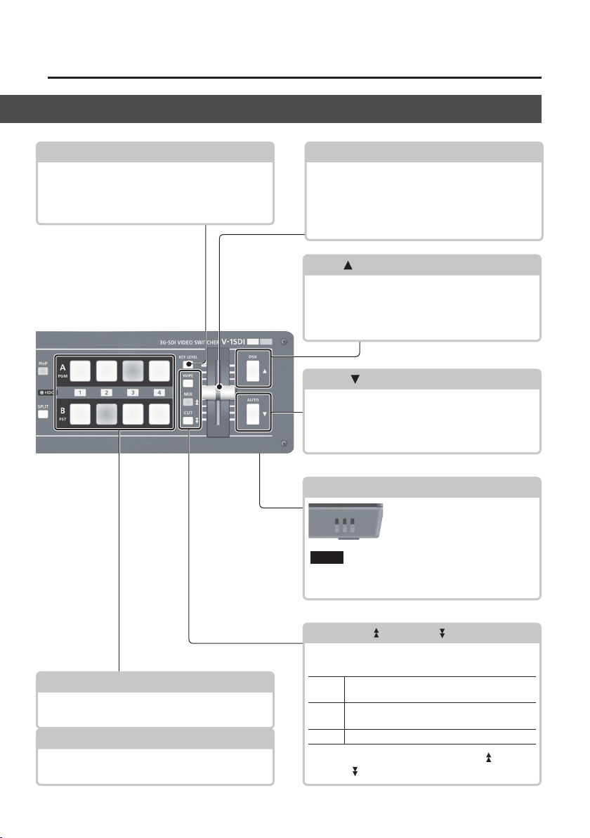
Top Panel/Front Panel
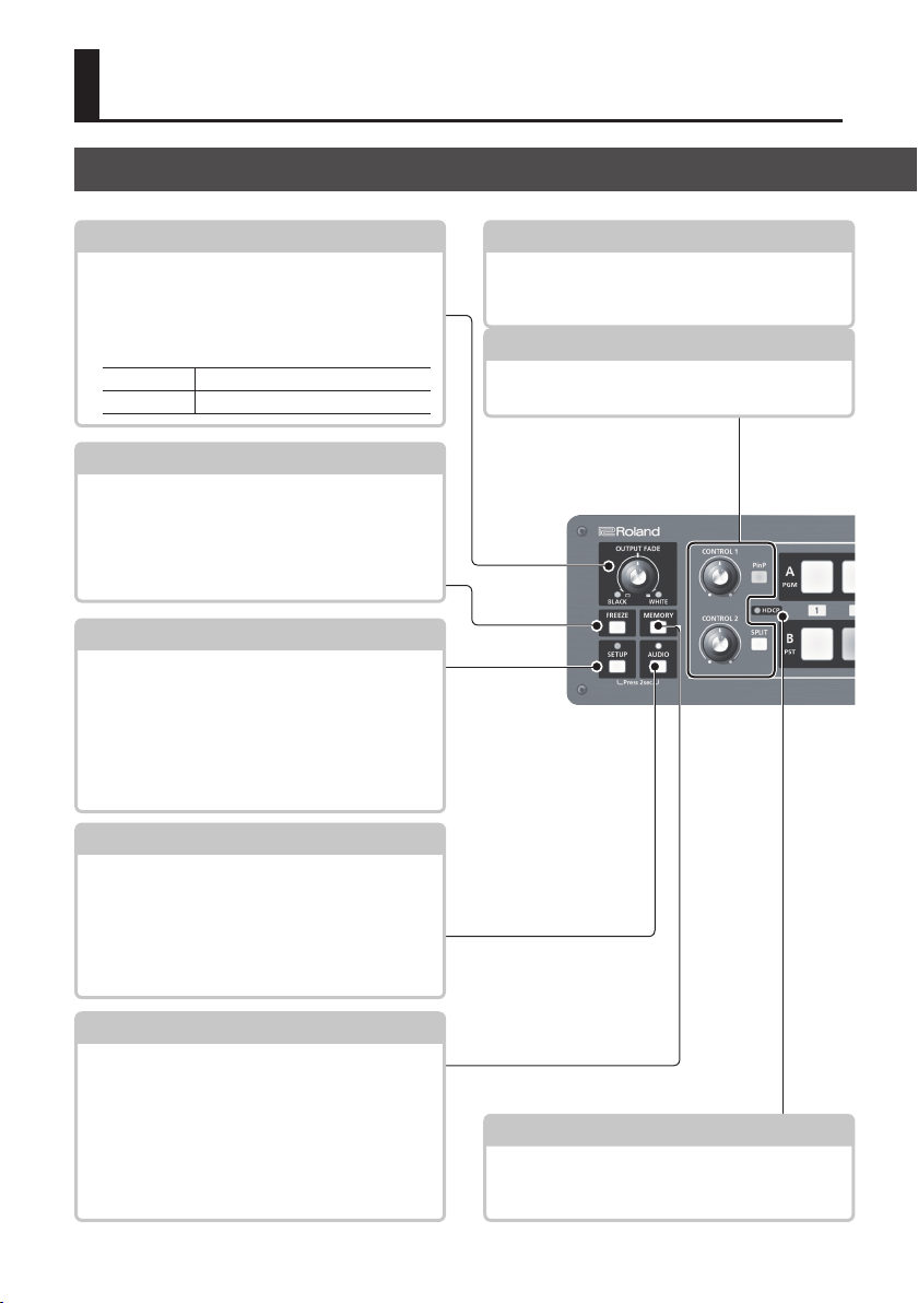
[OUTPUT FADE] Knob
This performs a fade-in or fade-out for the main
output video, and adjusts the volume level for
output audio.
5 The indicators on the left and right of the
[OUTPUT FADE] knob show the status of the fade.
Flashing Fade-in/fade-out in progress
Dark Normal output
[FREEZE] Button
5 This stops (freezes) input video. The [FREEZE]
button lights up during a freeze.
5 It outputs a captured still image.
5 It also outputs a still image transmitted from
V-1SDI RCS dedicated software.
[SETUP] Button
Pressing and holding the [SETUP] button (for 2
seconds or longer) to turn it on (lighted) displays
the SETUP menu on the monitor connected to the
MULTI-VIEW connector.
5 SETUP Indicator
This lights up on operation of a button or knob
for which panel lock (p. 30) is in eect.
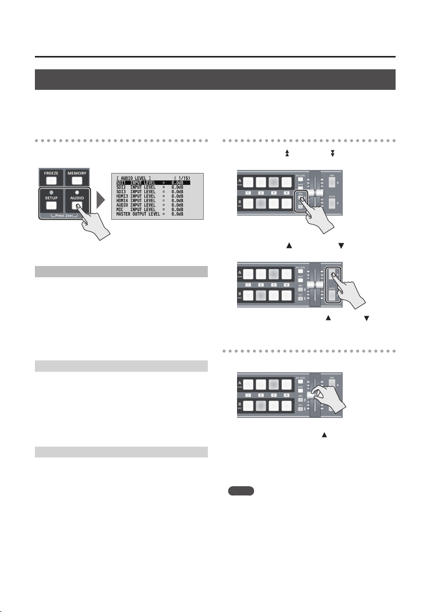
[AUDIO] Button
Pressing and holding the [AUDIO] button (for 2
seconds or longer) to turn it on (lighted) displays
the AUDIO menu on the monitor connected to the
MULTI-VIEW connector.
5 AUDIO Indicator
This indicates the audio input or output level.
p. 21, 26 p. 22
p. 20, 21
p. 12
p. 12, 26
[PinP] and [SPLIT] Buttons
These turn PinP, split, and other video compositing
on and o. When turned on, the [PinP] or [SPLIT]
button lights up.
[CONTROL 1] and [CONTROL 2] Knobs
When the [PinP], [SPLIT], or [KEY LEVEL] button is on
(lighted), these adjust the compositing eect.
p. 22
The memory function is turned on (lighted) while
the [MEMORY] button is held depressed. You
can save and recall up to eight types of settings,
including video and audio settings and operationpanel states.
When the memory function is on, the [A-1] through
[A-4] and [B-1] through [B-4] buttons function as
memory selection buttons 1 through 8.
6
p. 13[MEMORY] Button
p. 17HDCP Indicator
This lights up, ashes, or goes dark according to
HDCP (digital content protection) settings and the
connection status of HDCP-compatible equipment.
Panel Descriptions
[KEY LEVEL] Button
When this is turned on (lighted), the [CONTROL 1]
and [CONTROL 2] knobs function as shortcuts for
adjusting the key level and key gain during DSK
composition.
p. 25
A/B Fader
This functions as a T-Bar video fader. This performs
switching between the bus A (PGM) video and the
bus B (PST) video.
5 When a menu is displayed, this changes setting
values.
[DSK] ( ) Button
This turns DSK composition on or o. When it is
turned on, the [DSK] button lights up.
5 When a menu is displayed, these select menu
items.
[AUTO] (
This automatically switches between the bus A
video and the bus B video.
5 When a menu is displayed, these select menu
) Button
items.
p. 12, 18
p. 12, 24
p. 12, 19
Cooling-fan Exhaust Port
This expels internal heat to keep
temperatures inside the V-1SDI
cool.
Never obstruct the cooling-fan exhaust port.
NOTE
Obstructing the exhaust port might result in
a temperature rise inside the V-1SDI and lead
to malfunction due to heat.
[A-1]–[A-4] Buttons
These select the video to input to bus A of the video
mixer. The selected button lights up.
[B-1]–[B-4] Buttons
These select the video to input to bus B of the video
mixer. The selected button lights up.
p. 18
p. 18
[WIPE], [MIX] (
These select video transition eects. The selected
button lights up.
[WIPE]
[MIX]
[CUT] The picture switches instantly.
5 When a menu is displayed, the [MIX] ( ) and
[CUT] ( ) buttons page through the menu.
), and [CUT] ( ) Buttons
The original video is broken into by the next
video.
The two pictures are blended together as the
video is switched.
p. 12, 18
7
Panel Descriptions
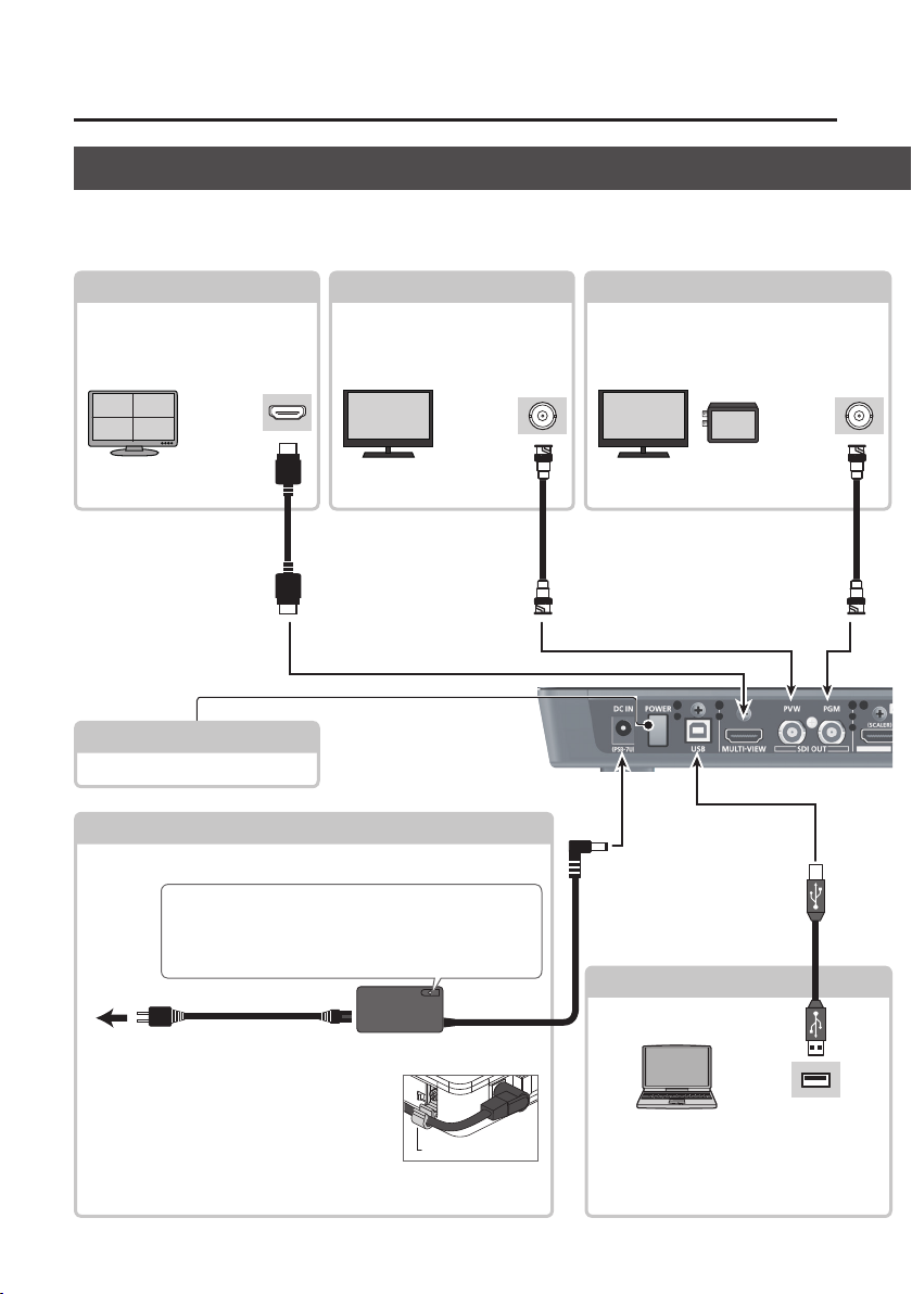
Rear Panel (Connecting Your Equipment)
* To prevent malfunction and equipment failure, always turn down the volume, and turn o all the units before making
any connections.
* Be sure to use cables and adaptor plugs with the proper connectors matching those of the other devices you are using.
MULTI-VIEW Connector (*1)
This outputs the incoming video
on channels 1 through 4 as a fourway split screen. Here you connect
a monitor capable of HDMI input.
HDMI input
* Menus are displayed on
the connected monitor.
(*1) You can also output
dierent video (p. 16).
[POWER] Button
p. 12, 16 PVW Connector (*1)
This displays the video to be
output next. Here you connect a
monitor capable of SDI input.
connector
p. 11
This turns the power on and o.
DC IN Connector
This is for connecting the included AC adaptor.
Place the AC adaptor so the side with the indicator faces
upwards and the side with printed information faces
downwards. The indicator will light when you plug the
AC adaptor into an AC outlet.
SDI input
connector
p. 16
PGM Connector
This outputs the video mixing result (main
output video). Here you connect a display
or a video recorder or other recording
device capable of SDI input.
USB Port p. 31
SDI input
connector
To AC Outlet
* To prevent the inadvertent disruption of
power to your unit (should the plug be pulled
out accidentally), and to avoid applying undue
stress to the jack, anchor the power cord using
the cord hook, as shown in the illustration.
For information on how to attach the cord hook, refer to “Attaching
the Power Cord Hook” (p. 10).
Power cord
AC adaptor
Cord hook
8
USB2.0 port
You use V-1SDI RCS dedicated software
to operate the V-1SDI remotely from a
connected computer.
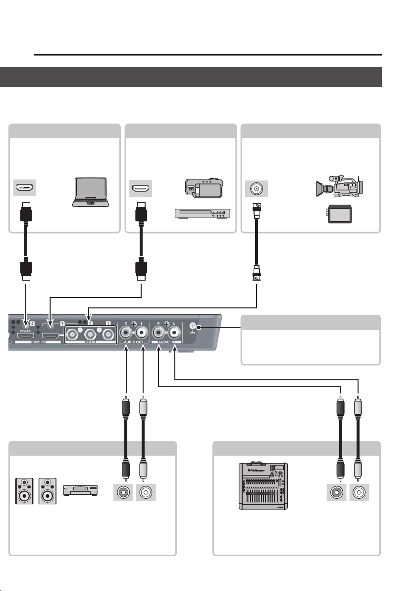
Panel Descriptions
* The V-1SDI is designed to radiate heat from the entire rear panel. Accordingly, the rear panel might become hot
during use, but this is not a malfunction.
HDMI IN 4 Connector
Here you input the HDMI signal
from a computer, a video camera,
Blu-ray Disc player, or other video
equipment.
HDMI output
connector
p. 14, 15 p. 16
HDMI IN 3 Connector
Here you input the HDMI signal
from a video camera, Blu-ray Disc
player, or other video equipment.
HDMI output
connector
SDI IN 1–3 Connectors
Here you input SDI signals from video
cameras, video recorders, and other video
equipment.
SDI output
connector
p. 16
Grounding Terminal
You connect this to an external ground.
For details, refer to “Grounding Terminal” in
“IMPORTANT NOTES” (p. 5).
AUDIO OUT Jacks
Audio input connectors
These output the results of the audio mix. Here
you connect an audio recording deck, amplier,
speakers, or other such equipment.
These accept RCA phono type plugs.
AUDIO IN Jacks
Audio output connectors
These are for incoming audio signals from an audio
mixer, portable music players, or other audio or
video equipment.
These accept RCA phono type plugs.
9
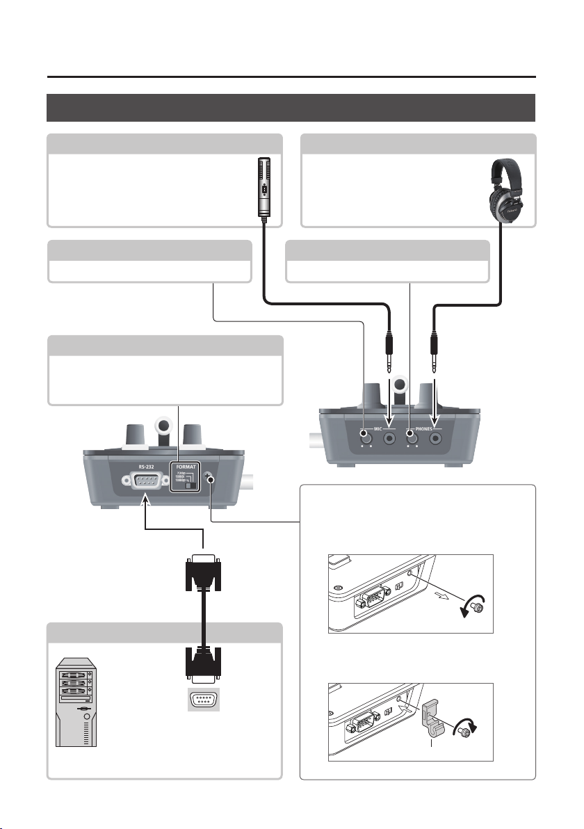
Panel Descriptions
Side Panel (Connecting Your Equipment)
MIC Jack
Here is where you connect a microphone.
This accepts a miniature stereo phone plug.
You can also use plug-in-power microphones.
[MIC] Knob
This adjusts microphone input sensitivity.
[FORMAT] Switch
This switches the input/output format.
* Before operating the [FORMAT ] switch, be sure the
power to the V-1SDI is turned o.
PHONES Jack
This is for connecting headphones. This
accepts a miniature stereo phone plug.
[PHONES] Knob
This adjusts the volume level for headphones.
p. 14
Attaching the Power Cord Hook
1. Detach the retainer screw indicated in the
gure.
RS-232 Connector p. 31
RS-232
connector
Here you connect a device used to
operate the V-1SDI by remote control
(such as an RS-232-compatible
computer).
10
2. Using the screw you removed in step 1,
secure the power-cord hook in place as
shown in the gure.
Cord hook
Basic Operation
Turning the Power On and O
Once everything is properly connected (p. 8–10), be
sure to follow the procedure below to turn on their
power. If you turn on equipment in the wrong order,
you risk causing malfunction or equipment failure.
* Before turning the unit on/o, always be sure to turn
the volume down. Even with the volume turned down,
you might hear some sound when switching the unit
on/o. However, this is normal and does not indicate a
malfunction.
Turning the Power On
1. Make sure all devices are turned o.
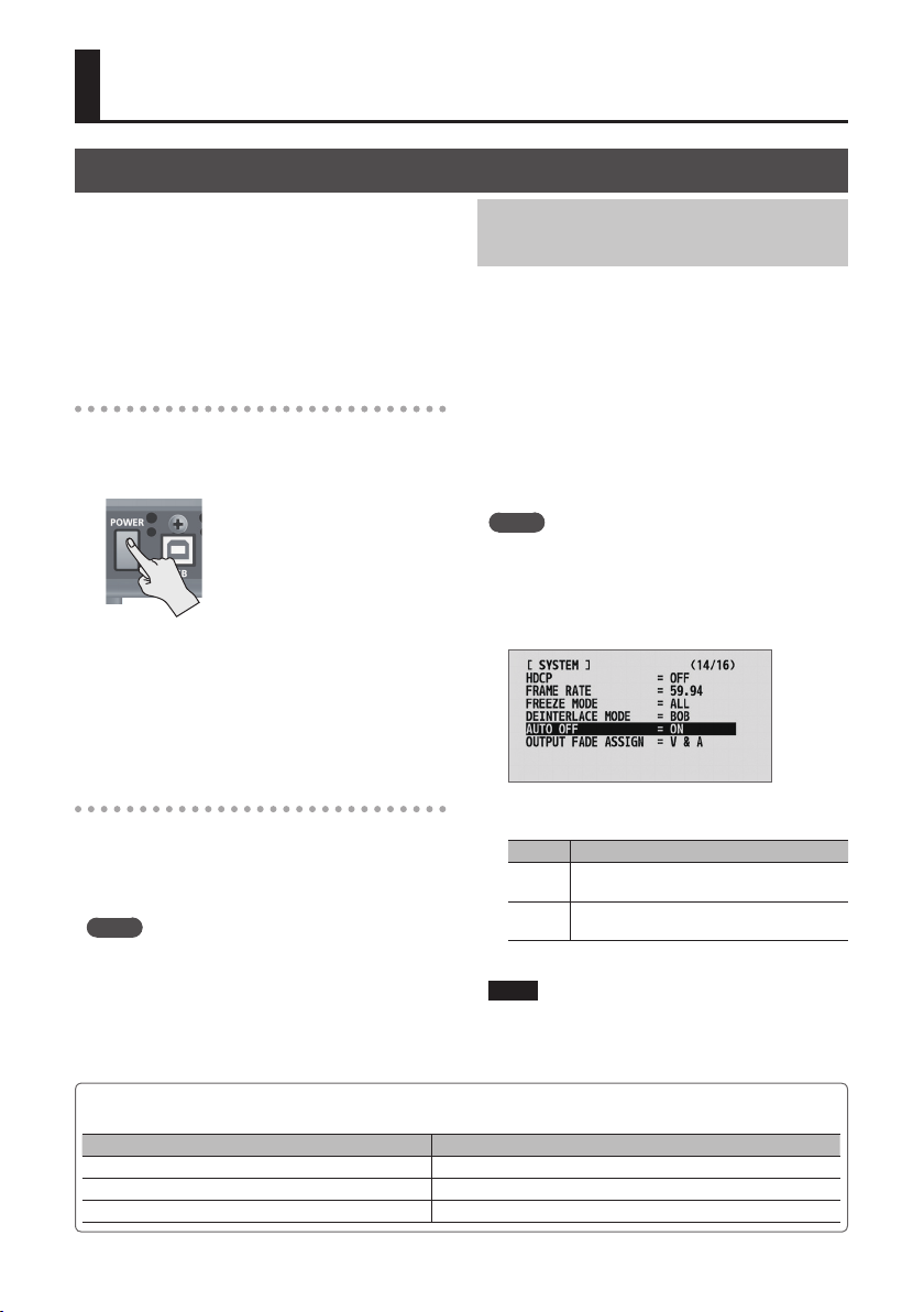
2. Press the [POWER] button on the rear panel of
the V-1SDI to turn on the power.
* This unit is equipped with a
protection circuit. A brief interval
(a few seconds) after turning the
unit on is required before it will
operate normally.
3. Turn on the power for the source devices.
Turn on the power to video cameras or
other source equipment connected to input
connectors on the V-1SDI.
4. Turn on the power for the output devices.
Turn on the power to projectors or other devices
connected to output connectors on the V-1SDI.
Turning O the Power Automatically
(Auto O)
Auto O is a feature that automatically turns o the
power after no operation for a specic period of
time. This helps prevent wasting electrical power.
By factory default, the Auto O function is set on.
When the states described below persist for 240
minutes, the Auto O function acts to automatically
turn o the power.
5 No operation performed on the V-1SDI
5 No audio or video input
To turn the Auto O function o or on, follow the
steps below to change the setting.
MEMO
5 When the power has been turned o by the Auto O
function, to restart, rst press the [POWER] button to
return it to the O position, then turn on the power.
1. Display the SETUP menu (p. 12), then select
“AUTO OFF.”
Turning the Power O
1. Turn o the power in the sequence of rst the
output equipment, and then the sources.
2. Press the [POWER] button on the V-1SDI to turn
o the power.
MEMO
5 The power to the V-1SDI turns o automatically if
a set interval elapses with no operation performed
(Auto O function).
If you don’t want the power to be turned o
automatically, disengage the Auto O function. For
details, refer to “Turning O the Power Automatically
(Auto O)” on this page.
Executing/Changing Specic Functions at Startup
Operation at startup Operation
Returning settings to the factory-default state at startup (p. 30)
Setting “HDCP” on the SETUP menu to “ON” at startup (p. 17) Hold down the [PinP] button and press the [POWER] button.
Setting “HDCP” on the SETUP menu to “OFF” at startup (p. 17) Hold down the [SPLIT] button and press the [POWER] button.
2. Use the A/B fader to set the Auto O function
on or o.
Value Explanation
The Auto O function is turned on. Power is
ON
turned o automatically.
The Auto O function is turned o. Power is
OFF
not turned o automatically.
3. Quit the menu (p. 12).
NOTE
5 Any settings that you are in the process of editing will
be lost when the power is turned o. If you have any
settings that you want to keep, you should save them
beforehand.
You can execute or change the following functions at
startup of the V-1SDI.
Hold down the [DSK] and [AUTO] buttons and press the [POWER] button.
11
Basic Operation
Using the Menus
This explains how to display menus and make settings for video and audio, and for the V-1SDI itself.
* Menus are shown only on the monitor connected to the MULTI-VIEW connector (HDMI) (p. 8).
Displaying/Exiting Menus
The V-1SDI has three types of menus (SETUP, AUDIO,
and INPUT STATUS).
* The button lights up during menu display.
SETUP Menu
You use this to make video-related settings and
settings for the V-1SDI itself.
1. Press and hold the [SETUP] button (for 2
seconds or longer) to display the SETUP menu.
2. Press the [SETUP] or [AUDIO] button to quit the
menu.
AUDIO Menu
You use this to make audio-related settings.
1. Press and hold the [AUDIO] button (for 2
seconds or longer) to display the AUDIO menu.
2. Press the [AUDIO] or [SETUP] button to quit the
menu.
INPUT STATUS Menu
This shows the incoming video formats and the
presence or absence of HDCP signals on the
respective video channels.
1. Press and hold the [SETUP] and [AUDIO] button
at the same time (for 2 seconds or longer) to
display the INPUT STATUS menu.
2. Press the [SETUP] or [AUDIO] button to quit the
menu.
12
Selecting Menu Items
1. Use the [MIX] ( ) and [CUT] ( ) buttons to
change pages.
2. Use the [DSK] ( ) and [AUTO] ( ) buttons to
move the cursor and select a menu item.
5 Pressing and holding the [DSK] ( ) or [AUTO] ( ) button
makes the cursor move rapidly.
Changing Setting Values
1. Use the A/B fader to change the setting value.
* For the following SETUP menu items, you apply the
setting by pressing the [DSK] (
elapse without applying the setting, the setting returns
to its original value, with no change applied.
5 VIDEO OUTPUT (3/16): COLOR SPACE
5 VIDEO OUTPUT (3/16): DVI-D/HDMI SIGNAL
5 SYSTEM (14/16): FRAME RATE
MEMO
5 Pressing and holding the [WIPE] button (for 2 seconds)
while a menu is displayed returns the currently selected
menu item to its default value. Continuing to press and
hold the [WIPE] button (for 5 seconds or longer) returns
all menu items on the currently selected page to their
default values.
5 For detailed information on menu items, refer to the
“Reference Manual” (PDF) available for download at the
Roland website.
http://proav.roland.com
) button. If 15 seconds
 Loading...