

Page 1
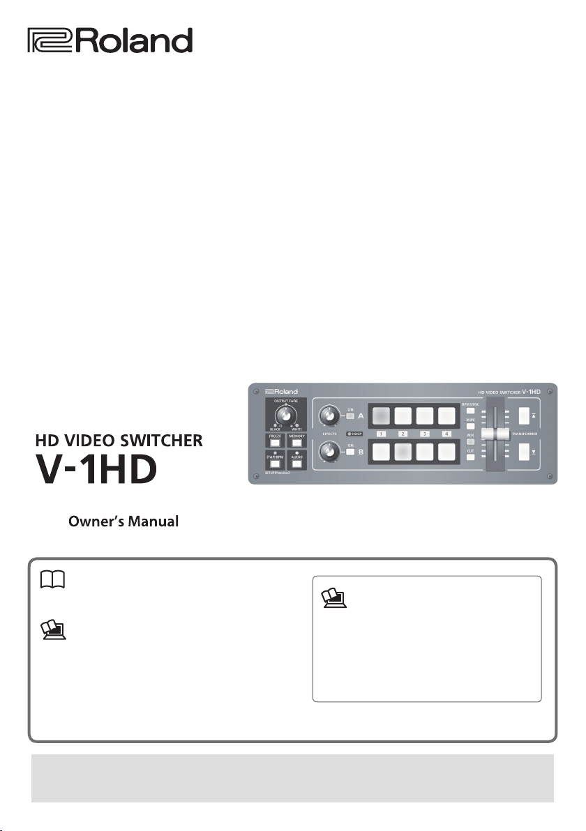
Owner’s Manual (this document)
Read this rst. It explains the basic things you need
to know in order to use the V-1HD.
PDF Manual (download from the Web)
5 Remote Control Guide
This manual covers remote control of the V-1HD
via MIDI.
Before using the V-1HD, ensure that its system program is at the most recent version. For information on
available upgrades for the system program, see the Roland website (http://proav.roland.com). You can check the
system program version by pressing and holding the [(TAP) BPM] button g “VERSION” at the SETUP menu.
To obtain the PDF manual
1. Enter the following URL in your computer.
http://proav.roland.com
I
2. Go to the V-1HD product page and click
the “Support” tab.
Copyright © 2015 ROLAND CORPORATION
Page 2
Contents
USING THE UNIT SAFELY . . . . . . . . . . . . . . . . . . . . . 3
IMPORTANT NOTES . . . . . . . . . . . . . . . . . . . . . . . . . . 5
Panel Descriptions . . . . . . . . . . . . . . . . . . . . . . . . . . 6
Top Panel/Front Panel . . . . . . . . . . . . . . . . . . . . . . . 6
Rear Panel (for Equipment Connections) . . . . . . . 8
Side Panel (for Equipment Connections) . . . . . . . . 10
Basic Operation . . . . . . . . . . . . . . . . . . . . . . . . . . . . . 11
Turning the Power On and O . . . . . . . . . . . . . . . . 11
Turning O the Power Automatically
Using the Menus . . . . . . . . . . . . . . . . . . . . . . . . . . . . 12
Saving/Recalling Settings (Memory) . . . . . . . . . . . 13
(Auto O)
. . . . . 11
Video Input/Output Settings . . . . . . . . . . . . . . . . . 14
Setting the Video Input/Output Format . . . . . . . . 14
Adjusting Output Video . . . . . . . . . . . . . . . . . . . . . . 14
Switching the View Mode of Preview Output . . . . 15
Inputting Copyright-protected (HDCP) Video . . . 15
Video Operations . . . . . . . . . . . . . . . . . . . . . . . . . . . . 16
Switching the Video . . . . . . . . . . . . . . . . . . . . . . . . . 16
Switching Using the A/B Fader . . . . . . . . . . . . . . 16
Switching Using the TRANSFORMER Buttons . . 17
Switching in Time with Music (BPM Sync) . . . . . 18
Switching Automatically (Auto Scan) . . . . . . . . . 19
Using a Dierent Transition Pattern . . . . . . . . . . 19
Applying a Fade to the Main Output Video
Freezing Input Video (Freeze) . . . . . . . . . . . . . . . . . 20
Before using this unit, carefully read “USING THE UNIT
SAFELY” (p. 3) and “IMPORTANT NOTES” (p. 5).
After reading, keep the document(s) including those
sections where it will be available for immediate reference.
(Output Fade)
. . . 20
Video Eect Operations . . . . . . . . . . . . . . . . . . . . . . 21
Using Filter Eects . . . . . . . . . . . . . . . . . . . . . . . . . . 21
Selecting a Filter Eect . . . . . . . . . . . . . . . . . . . . . 21
Applying Filter Eects . . . . . . . . . . . . . . . . . . . . . 21
Using Compositing Eects . . . . . . . . . . . . . . . . . . . 22
Selecting a Compositing Eect . . . . . . . . . . . . . . 22
Compositing Using Luminance Key . . . . . . . . . . 22
Compositing Using Chroma Key. . . . . . . . . . . . . 23
Compositing Using Picture-in-Picture . . . . . . . . 23
Compositing Using Split . . . . . . . . . . . . . . . . . . . 24
Audio Operations . . . . . . . . . . . . . . . . . . . . . . . . . . . 25
Adjusting the Volume Level . . . . . . . . . . . . . . . . . . 25
Applying Eects to Audio . . . . . . . . . . . . . . . . . . . . 26
Applying Eects to Input Audio . . . . . . . . . . . . . 26
Applying Eects to Output Audio . . . . . . . . . . . 27
Interlinking Audio Output to Video Switching
(Audio Follow)
. . 28
Other Features . . . . . . . . . . . . . . . . . . . . . . . . . . . . . . 29
Returning Settings to the Factory-
Operating the V-1HD by Remote Control . . . . . . . 29
default State (Factory Reset)
. . . . . 29
Appendices . . . . . . . . . . . . . . . . . . . . . . . . . . . . . . . . . 30
Troubleshooting . . . . . . . . . . . . . . . . . . . . . . . . . . . . 30
Menu List . . . . . . . . . . . . . . . . . . . . . . . . . . . . . . . . . . 31
MEMORY Menu . . . . . . . . . . . . . . . . . . . . . . . . . . . 31
AUDIO Menu . . . . . . . . . . . . . . . . . . . . . . . . . . . . . 32
SETUP Menu . . . . . . . . . . . . . . . . . . . . . . . . . . . . . 33
Transition Eects List . . . . . . . . . . . . . . . . . . . . . . . . 35
Block Diagram . . . . . . . . . . . . . . . . . . . . . . . . . . . . . . 36
Main Specications . . . . . . . . . . . . . . . . . . . . . . . . . 38
Dimensions . . . . . . . . . . . . . . . . . . . . . . . . . . . . . . . . 40
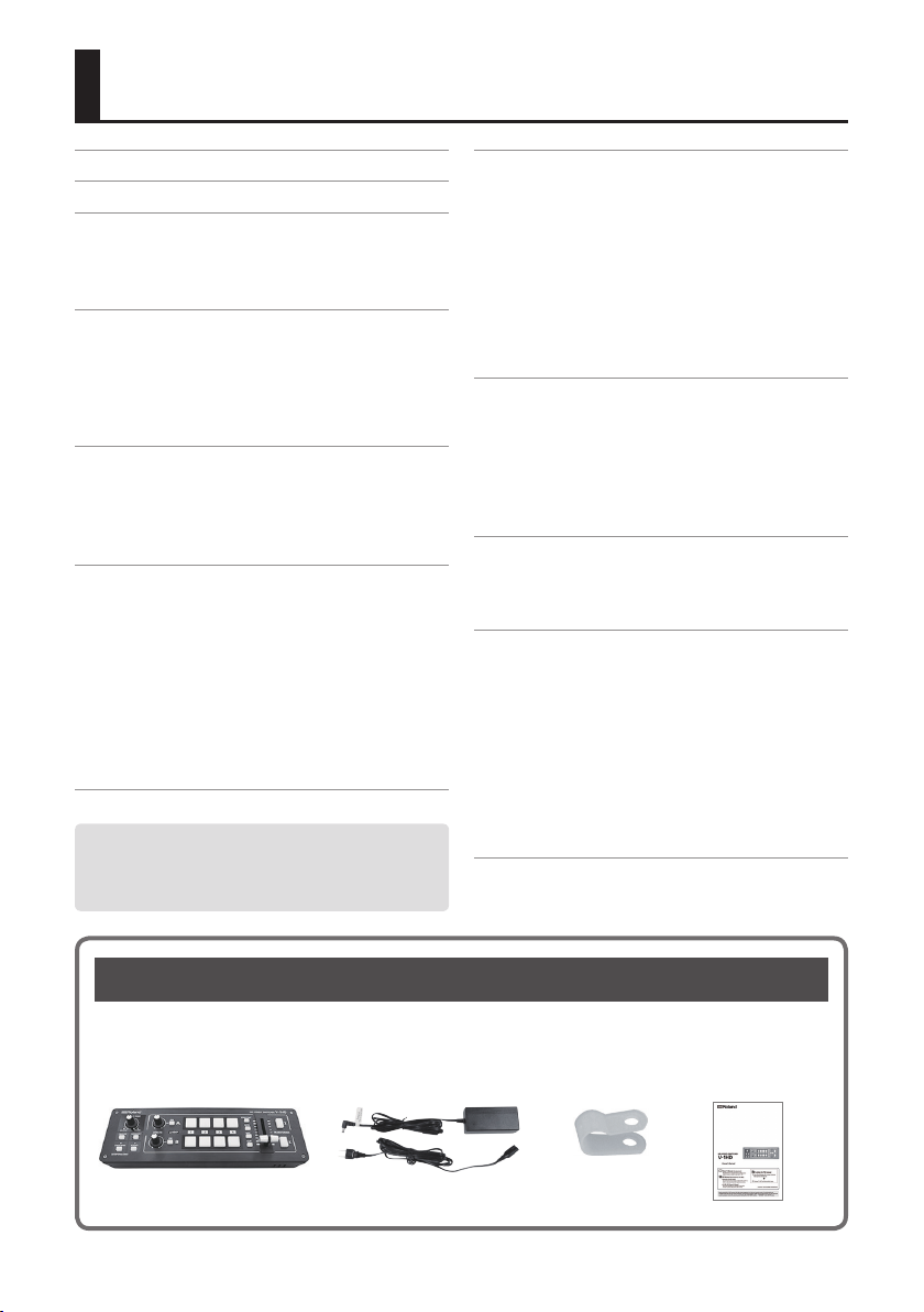
Checking the Included Items
The V-1HD includes the following items. Please take a moment to conrm that all of these items have
been included with the V-1HD. If you nd that any item is missing, contact the nearest authorized Roland
distributor in your country.
The Unit AC Adaptor/Power Cord Cord Hook Owner’s Manual
* The shape of the power cord’s plug
varies depending on the country.
2
Page 3
USING THE UNIT SAFELY
About WARNING and CAUTION Notices
ALWAYS OBSERVE THE FOLLOWING
About the Symbols
Used for instructions intended to alert
the user to the risk of death or severe
injury should the unit be used
improperly.
Used for instructions intended to alert
the user to the risk of injury or material
damage should the unit be used
improperly.
* Material damage refers to damage or
other adverse eects caused with
respect to the home and all its
furnishings, as well to domestic
animals or pets.
The symb ol alerts the user to important
instruc tions or warnings.The sp ecic meaning of the
symbol is determined by the design contained within
the triangle. In the case of th e symbol at left, it is used
for general cautions, warnings, or alerts to danger.
The symbol alerts the user to items that must never
be carried out (are forbidden). The specic thing that
must not be done is indicated by the design contained
within the circle. In the case of the symbol at left, it
means that the unit must never be disassembled.
The symbol alerts the user to things that must be
carried out. The specic thing that must be done is
indicated by the design contained within the circle. In
the case of the symbol at left, it means that the
power-cord plug must be unplugged from the outlet.
WARNING
To completely turn o power to the unit, pull out the plug
from the outlet
Even with the power switch turned o, this
unit is not completely separated from its main
source of power. When the power needs to
be completely turned o, turn o the power
switch on the unit, then pull out the plug from the
outlet. For this reason, the outlet into which you choose
to connect the power cord’s plug should be one that is
within easy reach and readily accessible.
Concerning the Auto O function
On this unit, the power is automatically turned
o after a predetermined amount of time has
passed since an operation was performed
(Auto O function).
If you do not want the power to be turned o
automatically, disengage the Auto O function (p. 11).
Do not disassemble or modify by yourself
Do not carry out anything unless you are
instructed to do so in the owner’s manual.
Otherwise, you risk causing malfunction.
Do not repair or replace parts by yourself
Refer all servicin-g to your retailer, the nearest
Roland Service Center, or an authorized Roland
distributor, as listed on the “Information.”
Do not place in an unstable location
Otherwise, you risk injury as the result of the
unit toppling over or dropping down.
WARNING
Do not use or store in the following types of locations
• Subject to temperature extremes (e.g.,
direct sunlight in an enclosed vehicle, near
a heating duct, on top of heat-generating
equipment); or are
• Damp (e.g., baths, washrooms, on wet
oors); or are
• Exposed to steam or smoke; or are
• Subject to salt exposure; or are
• Exposed to rain; or are
• Dusty or sandy; or are
• Subject to high levels of vibration and shakiness; or are
• Placed in a poorly ventilated location.
Use only the supplied AC adaptor and the correct voltage
Be sure to use only the AC adaptor supplied
with the unit. Also, make sure the line voltage
at the installation matches the input voltage
specied on the AC adaptor’s body. Other AC
adaptors may use a dierent polarity, or be designed for
a dierent voltage, so their use could result in damage,
malfunction, or electric shock.
Use only the supplied power cord
Use only the attached power cord. Also, the
supplied power cord must not be used with
any other device.
Do not bend the power cord or place heavy
objects on it
Otherwise, re or electric shock may result.
Avoid extended use at high volume
Use of the unit at high volume for extended
periods of time may cause hearing loss. If you
ever experience any hearing loss or ringing in
the ears, you should immediately stop using the unit and
consult a specialized physician.
3
Page 4
USING THE UNIT SAFELY
WARNING
Do not allow foreign objects or liquids to enter
unit; never place containers with liquid on unit
Do not place containers containing liquid (e.g.,
ower vases) on this product. Never allow
foreign objects (e.g., ammable objects, coins,
wires) or liquids (e.g., water or juice) to enter
this product. Doing so may cause short circuits,
faulty operation, or other malfunctions.
Turn o the unit if an abnormality or malfunction occurs
Immediately turn the unit o, remove the AC
adaptor from the outlet, and request servicing
by your retailer, the nearest Roland Service
Center, or an authorized Roland distributor, as
listed on the “Information” when:
• The AC adaptor or the power cord has been damaged; or
• If smoke or unusual odor occurs; or
• Objects have fallen into, or liquid has been spilled
onto the unit; or
• The unit has been exposed to rain (or otherwise has
become wet); or
• The unit does not appear to operate normally or
exhibits a marked change in performance.
Be cautious to protect children from injury
Always make sure that an adult is on hand to
provide supervision and guidance when using
the unit in places where children are present,
or when a child will be using the unit.
Do not drop or subject to strong impact
Otherwise, you risk causing damage or
malfunction.
Do not share an outlet with an unreasonable
number of other devices
Otherwise, you risk overheating or re.
Do not use overseas
Before using the unit in overseas, consult with
your retailer, the nearest Roland Service Center,
or an authorized Roland distributor, as listed
on the “Information.”
CAUTION
When disconnecting the power cord, grasp it by the plug
To prevent conductor damage, always grasp
the power cord by its plug when disconnecting
it from this unit or from a power outlet.
Periodically clean the power plug
An accumulation of dust or foreign objects
between the power plug and the power outlet
can lead to re or electric shock.
At regular intervals, be sure to pull out the power plug,
and using a dry cloth, wipe away any dust or foreign
objects that may have accumulated.
4
CAUTION
Disconnect the power plug whenever the unit will not be
used for an extended period of time
Fire may result in the unlikely event that a
breakdown occurs.
Route all power cords and cables in such a way as to prevent
them from getting entangled
Injury could result if someone were to trip on a
cable and cause the unit to fall or topple.
Avoid climbing on top of the unit, or placing heavy objects
on it
Otherwise, you risk injury as the result of the
unit toppling over or dropping down.
Never connect/disconnect a power plug if your hands are
wet
Otherwise, you could receive an electric shock.
Disconnect all cords/cables before moving the unit
Before moving the unit, disconnect the power
plug from the outlet, and pull out all cords
from external devices.
Before cleaning the unit, disconnect the power plug from
the outlet
If the power plug is not removed from the
outlet, you risk receiving an electric shock.
Whenever there is a threat of lightning, disconnect the
power plug from the outlet
If the power plug is not removed from the
outlet, you risk receiving an electric shock.
Keep small items out of the reach of children
To prevent accidental ingestion of the parts
listed below, always keep them out of the
reach of small children.
• Included Parts: Cord hook (p. 10)
• Removable Parts: Screw (p. 10)
Handle the ground terminal carefully
If you remove the screw from the ground
terminal, be sure to replace it; don’t leave it
lying around where it could accidently be
swallowed by small children. When refastening
the screw, make that it is rmly fastened, so it won’t
come loose.
Page 5

IMPORTANT NOTES
Power Supply
• Do not connect this unit to same electrical outlet
that is being used by an electrical appliance that
is controlled by an inverter or a motor (such as a
refrigerator, washing machine, microwave oven, or
air conditioner). Depending on the way in which the
electrical appliance is used, power supply noise may
cause this unit to malfunction or may produce audible
noise. If it is not practical to use a separate electrical
outlet, connect a power supply noise lter between
this unit and the electrical outlet.
• The AC adaptor will begin to generate heat after long
hours of consecutive use. This is normal, and is not a
cause for concern.
Placement
• Using the unit near power ampliers (or other
equipment containing large power transformers) may
induce hum. To alleviate the problem, change the
orientation of this unit; or move it farther away from
the source of interference.
• This unit may interfere with radio and television
reception. Do not use this unit in the vicinity of such
receivers.
• Noise may be produced if wireless communications
devices, such as cell phones, are operated in the
vicinity of this unit. Such noise could occur when
receiving or initiating a call, or while conversing.
Should you experience such problems, you should
relocate such wireless devices so they are at a greater
distance from this unit, or switch them o.
• When moved from one location to another where the
temperature and/or humidity is very dierent, water
droplets (condensation) may form inside the unit.
Damage or malfunction may result if you attempt to
use the unit in this condition. Therefore, before using
the unit, you must allow it to stand for several hours,
until the condensation has completely evaporated.
• Depending on the material and temperature of the
surface on which you place the unit, its rubber feet
may discolor or mar the surface.
• Do not place containers or anything else containing
liquid on top of this unit. Also, whenever any liquid
has been spilled on the surface of this unit, be sure to
promptly wipe it away using a soft, dry cloth.
Repairs and Data
• Before requesting servicing, back up the data stored
in the unit by writing down the stored information
or by using V-1HD RCS dedicated software (p. 29).
Although we will do our utmost to preserve the data
stored in your unit when we carry out repairs, in some
cases, such as when the memory section is physically
damaged, restoration of the stored content may be
impossible. Roland assumes no liability concerning
the restoration of any stored content that has been
lost.
Additional Precautions
• Any data stored within the unit can be lost as the
result of equipment failure, incorrect operation, etc.
To protect yourself against the irretrievable loss of
important data stored in the unit, use V-1HD RCS
dedicated software (p. 29) to make backups.
• Roland assumes no liability concerning the
restoration of any stored content that has been lost.
• Use a reasonable amount of care when using the
unit’s buttons, sliders, or other controls; and when
using its jacks and connectors. Rough handling can
lead to malfunctions.
• When disconnecting all cables, grasp the connector
itself—never pull on the cable. This way you will avoid
causing shorts, or damage to the cable’s internal
elements.
• To avoid disturbing others nearby, try to keep the
unit’s volume at reasonable levels.
• This unit allows you to switch images at high speed.
For some people, viewing such images can cause
headache, nausea, or other discomfort. Do not use
this unit to create video that might cause these types
of health problems. Roland Corporation will accept no
responsibility for any such health problems that may
occur in yourself or in viewers.
• Do not use connection cables that contain a built-in
resistor.
Maintenance
• Never use benzine, thinners, alcohol or solvents of
any kind, to avoid the possibility of discoloration and/
or deformation.
5
Page 6
Panel Descriptions
Top Panel/Front Panel
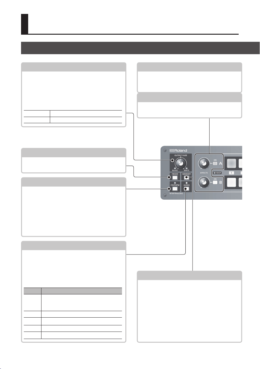
[OUTPUT FADE] Knob
This performs a fade-in or fade-out for the output
video.
Turning the control clockwise applies a white fade.
Turning it counterclockwise applies a black fade.
The indicators on the left and right of the [OUTPUT
FADE] knob show the status of the fade.
Flashing Fade-in/fade-out in progress
Dark Normal output
[FREEZE] Button
This stops (freezes) input video. The [FREEZE]
button lights up during a freeze.
[(TAP) BPM] Button
This sets the BPM (tempo) according to the timing
with which you tap the [(TAP) BPM] button. The
indicator above the [(TAP) BPM] button ashes in
sync with the current BPM setting.
5 Pressing and holding the [(TAP) BPM] button
(for 2 seconds or longer) to turn it on (lighted)
displays the SETUP menu on the monitor
connected to the PREVIEW connector.
[AUDIO] Button
Turning this on (lighted) displays the AUDIO
menu on the monitor connected to the PREVIEW
connector.
The [A-1] through [A-4] and [B-1] through [B-4]
buttons function as shortcut selection buttons for
the AUDIO menu.
Button AUDIO Menu
[A-1]
HDMI IN 1 LEVEL
:
:
[A-4]
HDMI IN 4 LEVEL
[B-1] AUDIO IN LEVEL
[B-2] MIC LEVEL
[B-3] MASTER OUT LEVEL
[B-4] AUDIO FOLLOW
p. 20
p. 20
p. 12, 18
p. 12, 25
EFFECTS A/EFFECTS B [ON] Buttons
These turn eects on and o for the respective
output video on bus A and bus B. When turned on,
the [ON] button lights up.
[EFFECTS A] and [EFFECTS B] Knobs
When an eect is on, these adjust the degree of
eect applied.
[MEMORY] Button
This turns the memory function on and o. When
this is turned on (lighted), you can save and recall
up to eight types of settings, including video and
audio settings and operation-panel states.
The [A-1] through [A-4] and [B-1] through [B-4]
buttons function as memory selection buttons 1
through 8.
5 Turning on the memory function displays the
MEMORY menu on the monitor connected to the
PREVIEW connector.
p. 21
p. 21
p. 12, 13
6
Page 7
Panel Descriptions
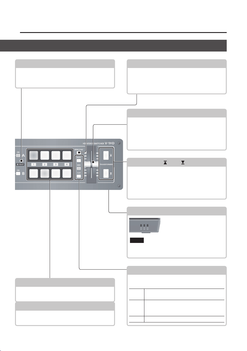
HDCP Indicator
This lights up, ashes, or goes dark according to
HDCP (digital content protection) settings and the
connection status of HDCP-compatible equipment.
p. 15 p. 18
[BPM SYNC] Button
This turns the BPM sync function on and o. When
this is turned on (lighted), the video on bus A and
bus B is switched in synchronization with the BPM
setting.
A/B Fader
This functions as a T-Bar video fader. This performs
switching between the bus A video and the bus B
video.
5 When a menu is displayed, this changes setting
values.
TRANSFORMER [ ] and [ ] Buttons
These perform the operations assigned to the
buttons, such as switching between the bus A video
and the bus B video, without using the A/B fader.
5 When a menu is displayed, these select menu
items.
p. 12, 16
p. 12, 17
Cooling-fan Xhaust Port
This expels internal heat to keep
temperatures inside the V-1HD
cool.
Never obstruct the cooling-fane xhaust port.
NOTE
Obstructing the xhaust port might result in a
temperature rise inside the V-1HD and lead to
malfunction due to heat.
[A-1]–[A-4] Buttons
These select the video to input to bus A of the video
mixer. The selected button lights up.
[B-1]–[B-4] Buttons
These select the video to input to bus B of the video
mixer. The selected button lights up.
p. 16
p. 16
[WIPE], [MIX], and [CUT] Buttons
These select video transition eects. The selected
button lights up.
The original video is broken into by the next
[WIPE]
video.
As the original picture gradually disappears,
[MIX]
the next video is overlaid and progressively
grows more visible.
[CUT] The picture switches instantly.
p. 16
7
Page 8
Panel Descriptions
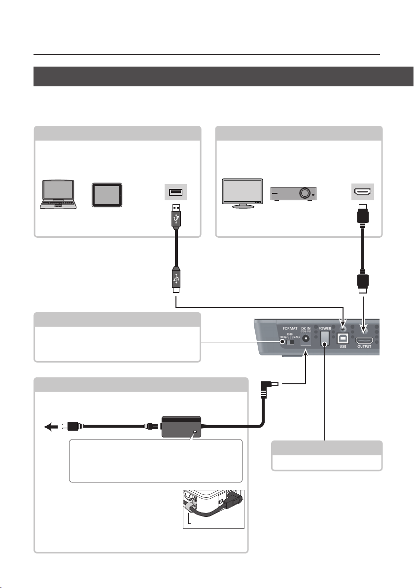
Rear Panel (for Equipment Connections)
* To prevent malfunction and equipment failure, always turn down the volume, and turn o all the units before making
any connections.
* Be sure to use cables and adaptor plugs with the proper connectors matching those of the other devices you are using.
USB Port
You use dedicated software to operate the V-1HD
remotely from a connected computer or tablet.
USB2.0 port
V-1HD RCS V-1HD Remote
[FORMAT] Switch
This switches the input/output format.
* Before setting the input/output format, rst be sure
to turn o the power to the V-1HD.
p. 29
p. 14
DC IN Connector
This is for connecting the included AC adaptor.
To AC Outlet
Power cord
AC adaptor
OUTPUT Connector
This outputs the video mixing result (main output
video). Here you can connect a device such as an
external display or projector.
HDMI input
connector
Place the AC adaptor so the side with the indicator faces
upwards and the side with printed information faces
downwards. The indicator will light when you plug the
AC adaptor into an AC outlet.
* To prevent the inadvertent disruption of
power to your unit (should the plug be pulled
out accidentally), and to avoid applying undue
stress to the jack, anchor the power cord using
the cord hook, as shown in the illustration.
For information on how to attach the cord hook, refer to “Attaching
the Power Cord Hook” (p. 10).
Cord hook
8
[POWER] Button
This turns the power on and o.
p. 11
Page 9
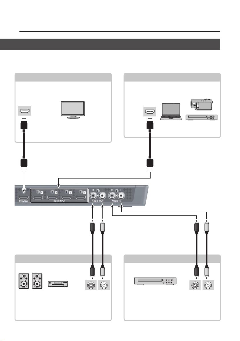
Panel Descriptions
* The V-1HD is designed to radiate heat from the entire rear panel. Accordingly, the rear panel might become hot during
use, but this is not a malfunction.
PREVIEW Connector
p. 15
This outputs the incoming video on channels 1
through 4 as a four-way split screen. You connect a
preview monitor here.
HDMI input
connector
* Alternatively, you can display only the video
currently being output (the same video sent
via the OUTPUT connector), or only the video
to be output next.
HDMI INPUT Connectors
Here you input video signals from video cameras,
Blu-ray Disc players, or other video equipment and
computers.
HDMI output
connector
AUDIO OUT Jacks
Audio input connectors
These output the results of the audio mix. Here
you connect an audio recording deck, amplier,
speakers, or other such equipment.
These accept RCA phono type plugs.
AUDIO IN Jacks
Audio output connectors
These are for incoming audio signals from an audio
mixer, portable music players, or other audio or
video equipment.
These accept RCA phono type plugs.
9
Page 10
Panel Descriptions
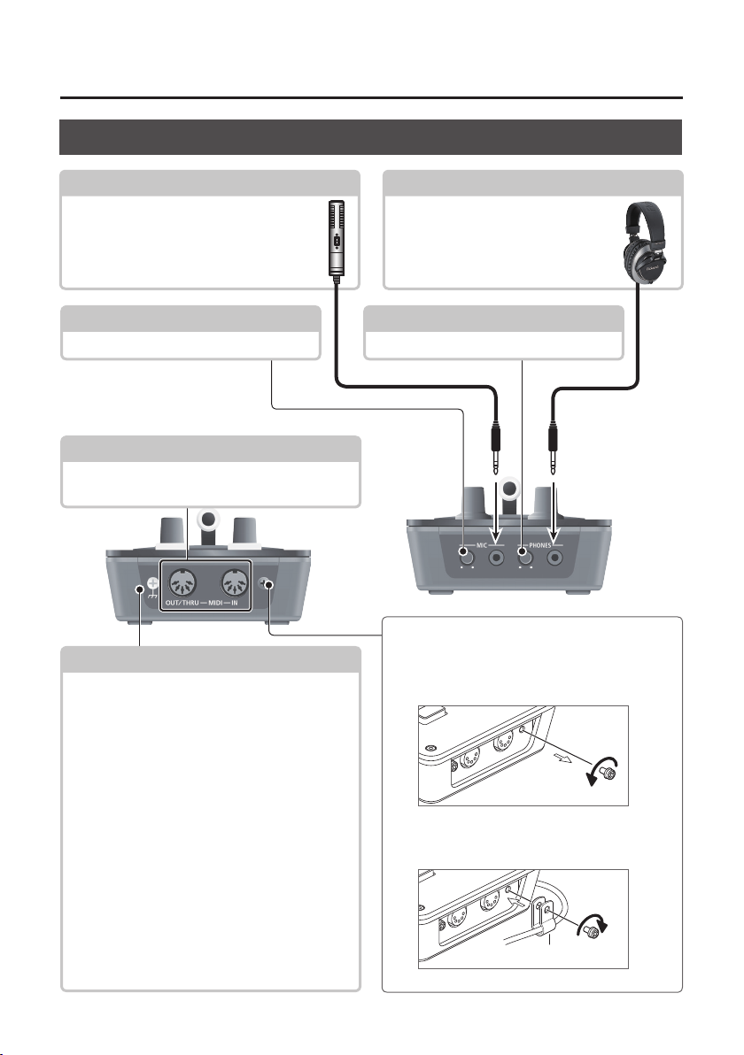
Side Panel (for Equipment Connections)
MIC Jack
Here is where you connect a microphone.
This accepts a miniature stereo phone plug.
You can also use plug-in-power microphones.
[MIC] Knob
This adjusts microphone input sensitivity.
MIDI OUT/THRU Connector, MIDI IN Connector
Here you connect a MIDI device used for remote
control.
p. 29
Grounding Terminal
Depending on the circumstances of a particular setup,
you may experience a discomforting sensation, or
perceive that the surface feels gritty to the touch
when you touch this device, microphones connected
to it, or the metal portions of other objects, such as
guitars. This is due to an innitesimal electrical charge,
which is absolutely harmless. However, if you are
concerned about this, connect the ground terminal
with an external ground. When the unit is grounded,
a slight hum may occur, depending on the particulars
of your installation. If you are unsure of the connection
method, contact the nearest Roland Service Center,
or an authorized Roland distributor, as listed on the
“Information.”
Unsuitable places for connection
5 Water pipes (may result in shock or electrocution)
5 Gas pipes (may result in re or explosion)
5 Telephone-line ground or lightning rod (may be
dangerous in the event of lightning)
PHONES Jack
This is for connecting headphones. This
accepts a miniature stereo phone plug.
[PHONES] Knob
This adjusts the volume level for headphones.
Attaching the Power Cord Hook
1. Detach the retainer screw indicated in the
gure.
2. Clamp -the power cord with the power-cord
hook as shown in the gure and secure in
place using the screw you removed in step 1.
Cord hook
10
Page 11
Basic Operation
Turning the Power On and O
Once everything is properly connected (p. 8–10), be
sure to follow the procedure below to turn on their
power. If you turn on equipment in the wrong order,
you risk causing malfunction or equipment failure.
* Before turning the unit on/o, always be sure to turn
the volume down. Even with the volume turned down,
you might hear some sound when switching the unit
on/o. However, this is normal and does not indicate a
malfunction.
Turning the Power On
1. Make sure all devices are turned o.
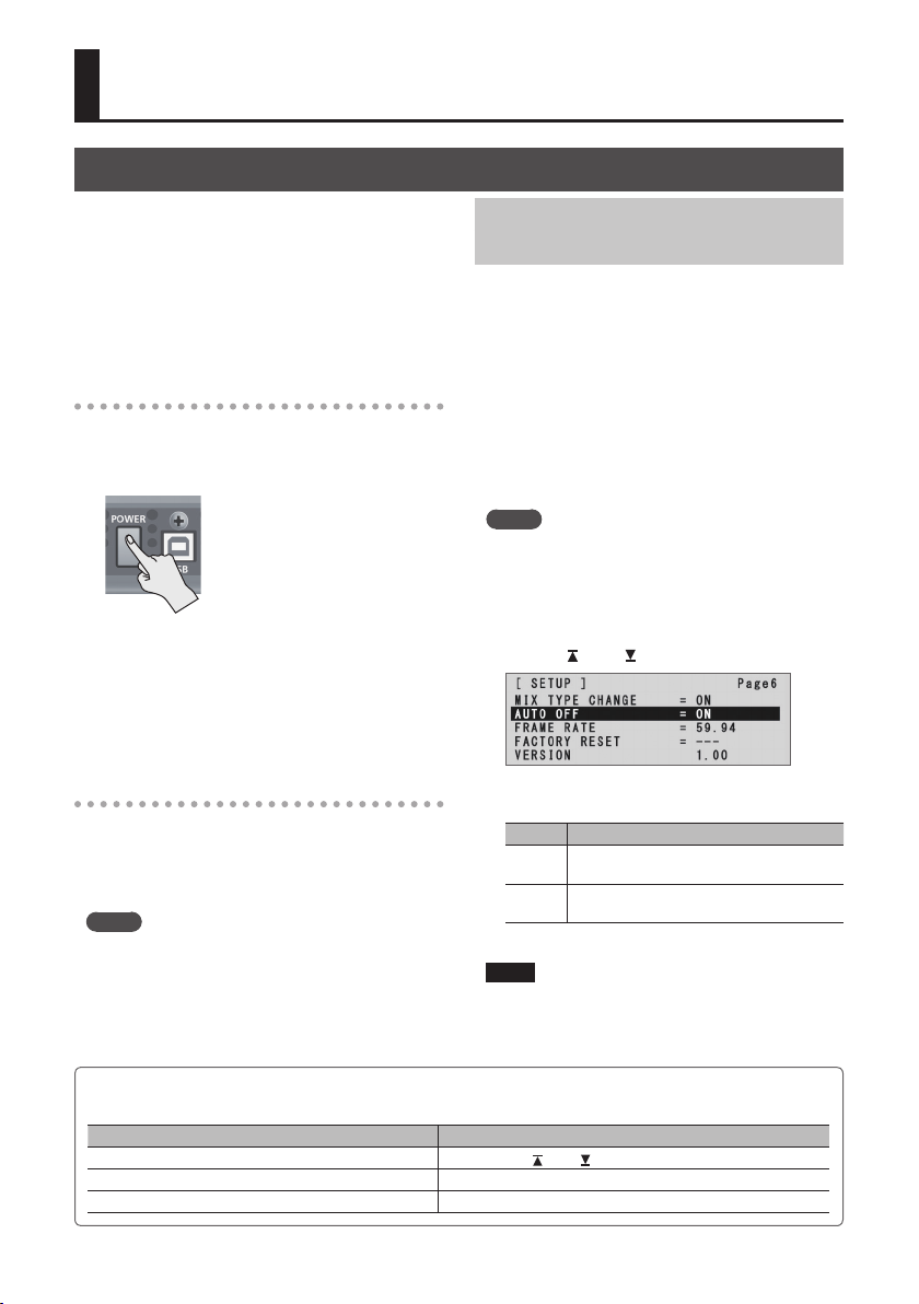
2. Press the [POWER] button on the rear panel of
the V-1HD to turn on the power.
* This unit is equipped with a
protection circuit. A brief interval
(a few seconds) after turning the
unit on is required before it will
operate normally.
3. Turn on the power for the source devices.
Turn on the power to video cameras or
other source equipment connected to input
connectors on the V-1HD.
4. Turn on the power for the output devices.
Turn on the power to projectors or other devices
connected to output connectors on the V-1HD.
Turning O the Power Automatically
(Auto O)
Auto O is a feature that automatically turns o the
power after no operation for a specic period of
time. This helps prevent wasting electrical power.
By factory default, the Auto O function is set on.
When the states described below persist for 240
minutes, the Auto O function acts to automatically
turn o the power.
5 No operation performed on the V-1HD
5 No audio or video input
To turn the Auto O function o or on, follow the
steps below to change the setting.
MEMO
5 When the power has been turned o by the Auto O
function, to restart, rst press the [POWER] button to
return it to the O position, then turn on the power.
1. Press and hold the [(TAP) BPM] button (for 2
seconds or longer) to display the SETUP menu.
2. Use the [ ] and [ ] buttons to select “AUTO OFF.”
Turning the Power O
1. Turn o the power in the sequence of rst the
output equipment, and then the sources.
2. Press the [POWER] button on the V-1HD to turn
o the power.
MEMO
5 The power to the V-1HD turns o automatically if
a set interval elapses with no operation performed
(Auto O function).
If you don’t want the power to be turned o
automatically, disengage the Auto O function. For
details, refer to “Turning O the Power Automatically
(Auto O)” on this page.
Executing/Changing Specic Functions at Startup
Operation at startup Operation
Returning settings to the factory-default state at startup (p. 29) Hold down the [
Setting “HDCP” on the SETUP menu to “ON” at startup (p. 15) Hold down the EFFECTS A [ON] button and press the [POWER] button.
Setting “HDCP” on the SETUP menu to “OFF” at startup (p. 15) Hold down the EFFECTS B [ON] button and press the [POWER] button.
3. Use the A/B fader to set the Auto O function
on or o.
Value Explanation
The Auto O function is turned on. Power is
ON
turned o automatically.
The Auto O function is turned o. Power is
OFF
not turned o automatically.
4. Press the [(TAP) BPM] button to quit the menu.
NOTE
5 Any settings that you are in the process of editing will
be lost when the power is turned o. If you have any
settings that you want to keep, you should save them
beforehand.
You can execute or change the following functions
at startup of the V-1HD.
] and [ ] buttons and press the [POWER] button.
11
Page 12
Basic Operation
Using the Menus
This explains how to display menus and make settings for video and audio, and for the V-1HD itself.
* The menu is shown on the monitor connected to the PREVIEW connector (p. 9).
NOTE
5 Video-switching operations cannot be performed while a menu is displayed.
Displaying/Exiting Menus
The V-1HD has three types of menus (SETUP,
MEMORY, and AUDIO).
The “MEMORY = 1” through “MEMORY = 8” items displayed
on the AUDIO menu and the MEMORY menu show that
settings are saved in memories 1 through 8.
When changing settings, you recall the memory number
(1 through 8) containing the settings you want to change
(p. 13).
* For SETUP menu settings, only a single set is saved in the unit.
* The button lights up during menu display.
SETUP Menu
1. Press and hold the [(TAP) BPM] button (for 2
seconds or longer) to display the SETUP menu.
2. Press the [(TAP) BPM] button to quit the menu.
MEMORY Menu
1. Press the [MEMORY] button to display the
MEMORY menu.
* This activates the memory function (p. 13), and the [A-1]
through [A-4] and [B-1] through [B-4] buttons function as
memory selection buttons 1 through 8.
2. Press the [A-1] through [A-4] or [B-1] through
[B-4] button for the memory number
containing the setting you want to change.
The currently selected button lights up in blue.
* Selecting a memory number also recalls the saved settings.
3. Press the [MEMORY] button to quit the menu.
AUDIO Menu
1. Press the [AUDIO] button to display the AUDIO
menu.
2. Press the [AUDIO] button to quit the menu.
12
Changing Setting Values
1. Use the [ ] and [ ] buttons to move the cursor
and select a menu item.
5 Pressing and holding the [ ] or [ ] button makes the
cursor move rapidly.
5 While the AUDIO menu is displayed, you can also select
menu items by pressing the following buttons.
Button Menu item
[A-1]
HDMI INPUT 1 LEVEL
:
:
[A-4]
HDMI INPUT 4 LEVEL
[B-1] AUDIO IN LEVEL
[B-2] MIC LEVEL
[B-3] MASTER OUT LEVEL
[B-4] AUDIO FOLLOW
2. Use the A/B fader to change the setting value.
* For the following SETUP menu items, you apply the
setting by pressing the [
without applying the setting, the setting returns to its
original value, with no change applied.
5 OUTPUT COLOR SPACE
5 OUTPUT DVI-D/HDMI
5 PREVIEW COLOR SPACE
5 PREVIEW DVI-D/HDMI
5 FRAME RATE
MEMO
5 The values of menu settings are saved in the unit when
you exit the menu. After changing settings, if you turn o
the power without rst quitting the menu, the changed
setting values are not saved.
5 For detailed information about menu items, refer to
“Menu List” (p. 31).
] button. If 10 seconds elapse
Page 13
Basic Operation
Saving/Recalling Settings (Memory)
You can take the current settings, including video and audio settings and the state of the operation panel, and
save them as a single set in the V-1HD’s internal memory, for later recall and use when needed. The V-1HD is
provided with eight memories.
Settings Saved in Memory
What you can save in memory are the MEMORY
menu and AUDIO menu settings and
the operation panel.
Each uses a dierent method for saving its values in
memory.
MEMORY Menu/AUDIO Menu Settings
<Procedure for Saving>
Values are saved in memory when you quit each
menu (p. 12).
State of the Operation Panel
State of the [OUTPUT FADE] knob
State of the [EFFECTS A] and [EFFECTS B] knobs
On/o status of the EFFECTS A and EFFECTS B [ON] buttons
[A-1] through [A-4] button selection
[B-1] through [B-4] button selection
On/o status of the [BPM SYNC] button
[MIX], [WIPE] and [CUT] button selection
State of the A/B fader
<Procedure for Saving>
Turn on the memory function (lighted) and save
the state of the operation panel in memory.
For more information on how to do this, refer to
“Saving the State of the Operation Panel” on this
page.
the state of
Saving the State of the Operation Panel
This saves the state of the operation panel, including
button and knob settings, in memory.
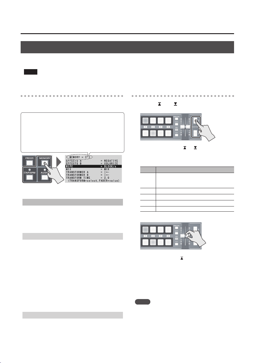
1. Press the [MEMORY] button to turn on the
memory function (lighted).
At this time the [A-1] through [A-4] and [B-1]
through [B-4] buttons function as memory
selection buttons 1 through 8.
The currently selected button lights up in blue.
2. Press and hold the [A-1] through [A-4] or [B-1]
through [B-4] button for the memory number
where you want to save the settings.
Memory number
1–4
5–8
The [A-1] through [A-4] and [B-1] through [B-4]
buttons all briey light up in blue, and the
current settings are saved.
3. To turn o the memory function, press the
[MEMORY] button again.
MEMO
5 SETUP menu items are not saved in memory. Only a
single set is saved in the unit.
5 You can recall settings at a specied memory number
at startup. Press and hold the [(TAP) BPM] button g use
“POWER ON LOAD” at the SETUP menu to specify the
memory number you want to recall.
NOTE
To update the state of the operation panel when
recalling a memory
By default, the state of the operation panel is not
updated when you recall a memory.
To update the state of the operation panel, press and
hold the [(TAP) BPM] button g at the SETUP menu, set
“MEMORY PANEL LOAD” to “ON.”
Recalling a Memory
1. Press the [MEMORY] button to turn on the
memory function (lighted).
2. Press the [A-1] through [A-4] or [B-1] through
[B-4] button for the memory number you want
to recall.
The settings are recalled. The currently selected
button lights up in blue.
3. To turn o the memory function, press the
[MEMORY] button again.
13
Page 14
Video Input/Output Settings
Setting the Video Input/Output Format
You set the input/output format to match the
incoming video signal.
* Before setting the input/output format, rst be sure to
turn o the power to the V-1HD.
1. Slide the [FORMAT] switch on the rear panel to
set the input/output format.
[FORMAT] switch Inputtable formats Output format
1080p 1080p, 1080i 1080p
1080i 1080p, 1080i 1080i
720p 720p 720p
MEMO
5 The V-1HD’s internal processing is progressive. Interlaced
input video is automatically converted to a progressive
signal.
The picture might appear jagged at this time, or the
picture in a PinP inset screen or preview four-way
split screen might waver. This is due to progressive
conversion, and is not a malfunction.
5 The methods for converting an interlaced signal to a
progressive signal are of two types: “BOB” and “WEAVE.”
This interpolates the top eld and bottom
BOB
WEAVE
To set the conversion method, press and hold the [(TAP)
BPM] button g use “DEINTERLACE MODE” at the SETUP
menu.
About Frame Rates
Frame rates that can be input are “59.94” and “50.”
Inputting video at a frame rate other than these
might result in no output or dropped frames.
To change the frame rate, press and hold the [(TAP)
BPM] button g select “FRAME RATE” at the SETUP
menu g select “59.94” or “50” g press the [
eld, and unites them in a single frame.
This is optimal for video that contains much
movement.
This joins the top eld and bottom eld in
a single frame. This is optimal for video that
contains little movement.
] button.
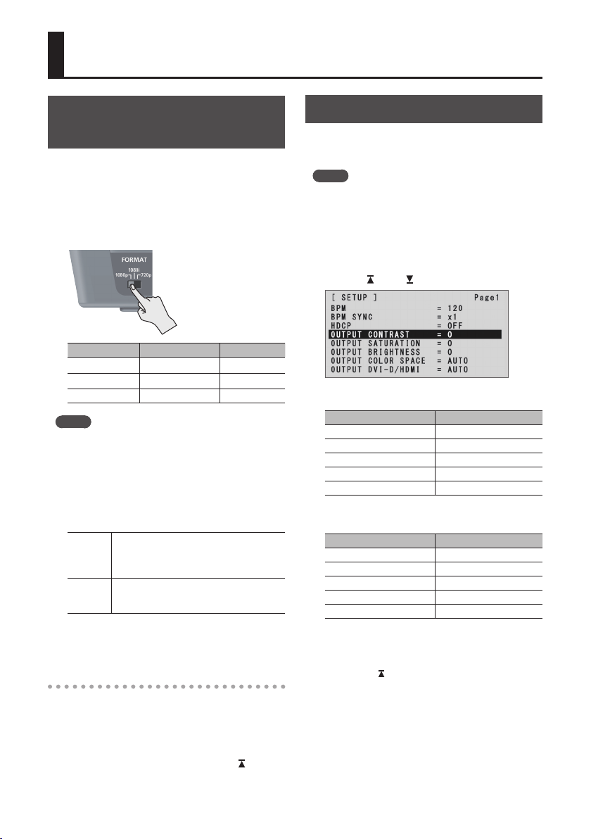
Adjusting Output Video
You can adjust the main output video or preview
output video to match the equipment receiving
output from the V-1HD.
MEMO
5 You can output a color bar, useful for adjusting the
image quality of a display. Press and hold the [(TAP) BPM]
button g set “COLOR BAR OUTPUT” at the SETUP menu
to “ON.”
1. Press and hold the [(TAP) BPM] button (for 2
seconds or longer) to display the SETUP menu.
2. Use the [ ] and [ ] buttons to select an item.
You use the following items to adjust the main
output video.
Menu item Explanation
OUTPUT CONTRAST This adjusts the contrast.
OUTPUT SATURATION This adjusts the saturation.
OUTPUT BRIGHTNESS This adjusts the brightness.
OUTPUT COLOR SPACE This sets the color space.
OUTPUT DVI-D/HDMI This sets the output mode.
You use the following items to adjust the preview
output video.
Menu item Explanation
PREVIEW CONTRAST This adjusts the contrast.
PREVIEW SATURATION This adjusts the saturation.
PREVIEW BRIGHTNESS This adjusts the brightness.
PREVIEW COLOR SPACE This sets the color space.
PREVIEW DVI-D/HDMI This sets the output mode.
3. Use the A/B fader to adjust the main output
video or preview output video.
* The settings for the following menu items are applied by
pressing the [
applying the setting, the setting returns to its original
value, with no change applied.
5 OUTPUT COLOR SPACE
5 OUTPUT DVI-D/HDMI
5 PREVIEW COLOR SPACE
5 PREVIEW DVI-D/HDMI
4. Press the [(TAP) BPM] button to quit the menu.
] button. If 10 seconds elapse without
14
Page 15

Video Input/Output Settings
Switching the View Mode of Preview Output
Three types of view modes are available for the
V-1HD’s preview output.
1. Press and hold the [(TAP) BPM] button (for 2
seconds or longer) to display the SETUP menu.
2. Use the [ ] and [ ] buttons to select “PREVIEW
OUT.”
3. Use the A/B fader to set the view mode.
Value Explanation
This displays the incoming video on channels
1 through 4 as a four-way split screen.
The input video is arranged as shown below.
Channel 1 Channel 2
MULTIVIEW
OUTPUT This displays the video currently being output.
PREVIEW This displays the video to be output next.
4. Press the [(TAP) BPM] button to quit the menu.
Channel 3 Channel 4
The video is displayed with a colored border
that is interlinked with the selected [A-1]
through [A-4] or [B-1] through [B-4] button.
Red border: Video currently being output
Green border: Video to be output next
Inputting Copyright-protected (HDCP) Video
To input copyright-protected (HDCP) video from a
Blu-ray Disc player or the like, you make the setting for
enabling HDCP input.
* The V-1HD must be connected to an HDCP compatible
display for HDCP protected video to be connected.
What’s HDCP?
HDCP is copyright-protection technology that prevents
unlawful copying of content by encoding the path when
sending digital signals from a video playback device to a
display monitor or other display equipment.
1. Press and hold the [(TAP) BPM] button (for 2
seconds or longer) to display the SETUP menu.
2. Use the [ ] and [ ] buttons to select “HDCP.”
3. Use the A/B fader to set this to “ON.”
Value Explanation
Copyright-protected (HDCP) video can be input.
ON
HDCP is also added to the video that is output.
OFF Copyright-protected (HDCP) video cannot be input.
4. Press the [(TAP) BPM] button to quit the menu.
Operation of the HDCP indicator
The HDCP indicator on the top panel operates as
follows, regardless of input.
“HDCP”
Indicator
setting
Lighted ON
Flashing ON
Dark OFF —
Connection status
An HDCP-compatible device is connected
to the OUTPUT or PREVIEW connector.
No HDCP-compatible device is connected
to the OUTPUT or PREVIEW connector.
Alternatively, a device that does not
support HDCP is connected.
15
Page 16

Video Operations
Switching the Video
You can switch the video input to bus A and to bus B of the video mixer.
Switching Using the A/B Fader
You operate the A/B fader to switch between two video feeds. The video on the bus toward which the A/B fader
is ipped is output (A/B mode).
1. Use the [A-1] through [A-4] and [B-1] through
[B-4] buttons to select the video to input on bus
A and bus B.
Bus A
Bus B
Lighted in red: Video currently being output
Lighted in green: Video to be output next
Lighted in white: Channel with video input
2. Press the [WIPE], [MIX], or [CUT] button to
select a transition eect.
The selected button lights up.
Button Explanation
The original video is broken into by the next
[WIPE]
video.
As the original picture gradually disappears, the
next video is overlaid and progressively grows
[MIX]
more visible.
[CUT] The picture switches instantly.
MEMO
5 You can change the transition pattern used for a wipe
or mix transition. For details, refer to “Using a Dierent
Transition Pattern” (p. 19).
3. Move the A/B fader to the bus A position or the
bus B position.
The output video is switched
MEMO
5 You can change the color in which the [A-1] through
[A-4] and [B-1] through [B-4] buttons light up. Press and
hold the [(TAP) BPM] button g at the SETUP menu, use
“PGM LED” (buttons for current video output) or “PST
LED” (buttons for next video output) to make the setting.
5 Directly selecting the video channel at the bus position of
the video currently being output switches the video with
a cut, regardless of any selection of a transition eect.
About the Operation Mode for Video Transitions
Two operation modes are available for video
transitions made using the A/B fader: the “A/B
mode” and the “PGM/PST mode.”
To set the operation mode, press and hold the
[(TAP) BPM] button g use “A/B MODE” at the
SETUP menu.
A/B Mode
The video on the bus toward which the A/B fader is ipped
is output.
PGM/PST Mode
The video at the PGM (bus A) position is always output,
and for PST (the bus B position), these select the video to
be output next.
Operating the A/B fader causes the selected video at the
PST (bus B) position to be output from the PGM (bus A)
position.
* Bus assignments made using EFFECTS [ON] buttons or
TRANSFORMER buttons (bus A or bus B) do not change.
PGM Lighted in red:
Video currently being output
PST Lighted in green:
Video to be output next
16
Page 17

Video Operations
Switching Using the TRANSFORMER Buttons
You can switch video using the TRANSFORMER buttons, without using the A/B fader. This section describes the
operations, using the factory-default memory number 1 settings as an example.
1. Use the [A-1] through [A-4] and [B-1] through
[B-4] buttons to select the video to input on bus
A and bus B.
Bus A
Bus B
Lighted in red: Video currently being output
Lighted in green: Video to be output next
Lighted in white: Channel with video input
2. Press a TRANSFORMER button to switch the
video on bus A and bus B.
Pressing the TRANSFORMER [ ] button
switches to the video on bus A.
Pressing the TRANSFORMER [ ] button
switches to the video on bus B.
* By factory default, the operation of the TRANSFORMER
buttons is set as follows in memory number 1.
MEMORY menu item Value
TRANSFORMER A
TRANSFORMER B
MEMO
5 You can change the operations performed when
TRANSFORMER buttons are pressed. For details, refer to
“Changing the Operation of the TRANSFORMER Buttons”
on this page.
5 When you use the TRANSFORMER buttons to switch
video, the actual output might come to dier from the
position of the A/B fader.
Operating the A/B fader while in this state yields no
change in output until the position of the A/B fader
matches the actual output.
5 You can make the TRANSFORMER buttons dark. Press
and hold the [(TAP) BPM] button g set “TRANSFORMER
LED” on the SETUP menu to “OFF.”
Changing the Operation of the
TRANSFORMER Buttons
1. Press the [MEMORY] button to display the
MEMORY menu.
2. Use the [ ] and [ ] buttons to select
“TRANSFORMER A” or “TRANSFORMER B”
3. Use the A/B fader to specify the operation of
the TRANSFORMER buttons.
Value Explanation
NONE Button operation is disabled. (*1)
The video is switched to the video for the
TRANS-
bus position of the pressed button until you
FORM
release the button.
Pressing a button switches the video to the
video for the bus position of the pressed
button. (*2)
Each press of a button switches the bus A and
bus B video. (*2)
A white picture is output until the button is
WHITE
released.
A black picture is output until the button is
BLACK
released.
BPM
The [BPM SYNC] button is selected until the
SYNC
pressed button is released.
The [WIPE] button is selected until the
WIPE
pressed button is released.
The [MIX] button is selected until the pressed
MIX
button is released.
The [CUT] button is selected until the pressed
CUT
button is released.
The eect for the bus position of the pressed
EFFECTS
button is turned on until you release the button.
(*1) The TRANSFORMER buttons are dark when this is set
to “NONE.”
(*2) When a mix or wipe has been selected as the
transition eect, the value set for “TRANSFORM TIME”
at the MEMORY menu is used for the video transition
time.
4. Press the [MEMORY] button to quit the menu.
17
Page 18

Video Operations
Switching in Time with Music (BPM Sync)
You can switch video in time with a musical beat. The video is switched automatically, with no operation of the
A/B fader or the TRANSFORMER buttons.
Setting BPM Using a Numerical Value
Setting BPM using a numerical value makes the
video switch beat by beat.
1. Use the [A-1] through [A-4] and [B-1] through
[B-4] buttons to select the video to input on bus
A and bus B.
Bus A
Bus B
2. Press and hold the [(TAP) BPM] button (for 2
seconds or longer) to display the SETUP menu.
3. Use the [ ] and [ ] buttons to select “BPM.”
4. Use the A/B fader to set the BPM.
The setting range for BPM is from 20 to 250.
5. Press the [BPM SYNC] button to turn on BPM
sync (lighted).
Setting BPM by the Timing of Pressing the
[(TAP) BPM] Button
You can sets the BPM according to the timing with
which you press the [(TAP) BPM] button, and make
the video switch beat by beat.
1. Use the [A-1] through [A-4] and [B-1] through
[B-4] buttons to select the video to input on bus
A and bus B.
Bus A
Bus B
2. Press the [BPM SYNC] button to turn on BPM
sync (lighted).
The video is automatically switched in time with
the value currently set for BPM.
3. Press the [(TAP) BPM] button repeatedly to set
the BPM.
The [BPM SYNC] button lights up, and the video
is automatically switched in time with the value
set for BPM.
6. To turn o BPM sync, press the [BPM SYNC]
button a second time.
MEMO
5 You can also change the speed at which the video is
switched to a speed that is a multiple of the value set for
BPM. the [(TAP) BPM] button g use “BPM SYNC” at the
SETUP menu to make the setting.
5 When you use BPM sync to switch video, the actual
output might come to dier from the position of the
A/B fader.
Operating the A/B fader while in this state yields no
change in output until the position of the A/B fader
matches the actual output.
18
Repeatedly press the [(TAP) BPM] button in
time with a musical beat. The BPM changes
continuously according to the timing with which
you press the [(TAP) BPM] button.
The video is automatically switched in time with
the changed BPM.
4. To turn o BPM sync, press the [BPM SYNC]
button a second time.
Page 19

Video Operations
Switching Automatically (Auto Scan)
The video on channels 1 through 4 is switched
automatically in sequence.
MEMO
5 Any channels carrying no video input are skipped.
5 Switching the video manually is not possible while an
automatic switch is in progress.
1. Press and hold the [(TAP) BPM] button (for 2
seconds or longer) to display the SETUP menu.
2. Use the [ ] and [ ] buttons to select “AUTO
SCAN.”
3. Use the A/B fader to set this to “ON.”
Value Explanation
Video automatic switching is turned on. The
ON
video on channels 1 through 4 is switched
automatically.
The video automatic switching feature is turned
OFF
o.
5 You can use the following SETUP menu items to set the
transition interval for video display and the time applies
to the video transition.
Menu item Explanation
AUTO SCAN
TIME
AUTO SCAN
TRANS TIME
* If the time the video transition takes is longer than
the video display interval, the next transition starts
before the current transition is complete.
4. Press the [(TAP) BPM] button to quit the menu.
This sets the display interval for video
within a range of 1 to 120 seconds.
This sets the time the video transition
takes, within a range of 0.0 to 4.0 seconds.
* These are eective when a mix or wipe
is selected as the transition eect.
Using a Dierent Transition Pattern
A variety of transition patterns are available for mix
and wipe transition eects.
To use a dierent pattern, change the transition
pattern assigned to the [MIX] or [WIPE] button.
1. Press the [MEMORY] button to display the
MEMORY menu.
2. Use thee [ ] and [ ] buttons to select “WIPE”
or “MIX.”
3. Use the A/B fader to change the transition
pattern.
* For a list of transition-pattern types, refer to “Transition
Eects List” (p. 35).
4. Press the [MEMORY] button to quit the menu.
MEMO
5 When the [WIPE] button is selected, you can change the
transition pattern with each press of the [WIPE] button.
Press and hold the [(TAP) BPM] button g set “WIPE T YPE
CHANGE” at the SETUP menu to “ON.”
The procedure is similar for the [MIX] button. Set “MIX
TYPE CHANGE” at the SETUP menu to “ON.”
19
Page 20

Video Operations
Applying a Fade to the Main Output Video (Output Fade)
You can apply a fade to the V-1HD’s main output video.
This lets you make the main output video fade to a
black (or white) picture at times when you want to
suppress video output, such as during intervals in a
presentation, event or band performance.
Applying a Fade-out
1. Turn the [OUTPUT FADE] knob all the way
clockwise or counterclockwise.
Turning the [OUTPUT FADE] knob clockwise
performs a fade-out to white, and turning the
knob counterclockwise performs a fade-out to
black.
Applying a fade makes the indicators to the left
or right of the knob ash.
Applying a Fade-in
1. Return the [OUTPUT FADE] knob to its center
position.
Freezing Input Video (Freeze)
This temporarily pauses the incoming video.
You can apply transition eects and other eects
during a video freeze.
Setting the Freeze Mode
Two operation modes are available for freezes: the
“ALL mode” and the “SELECT mode.”
By factory default, this is set to “ALL” (freeze all
incoming video).
If you want to select the input video to freeze, press
and hold the [(TAP) BPM] button g set “FREEZE
MODE” at the SETUP menu to “SELECT.”
Freezing Input Video
When the Freeze Mode Is Set to “ALL”
1. Press the [FREEZE] button to turn on freeze
(lighted).
All video that is input freezes.
2. To turn o freeze, press the [FREEZE] button a
second time.
The indicator stops ashing and lights up
steadily, and output starts.
20
When the Freeze Mode Is Set to “SELECT”
1. Press the [FREEZE] button to turn on freeze
(lighted).
The [A-1] through [A-4] buttons all ash in red.
2. Press one of the [A-1] through [A-4] buttons to
select the incoming video you want to freeze.
The selected input video freezes.
3. To turn o freeze, press the [FREEZE] button a
second time.
Page 21

Video Eect Operations
You can apply eects to the main output video. The V-1HD has nine types of built-in lter eects and ten types
of built-in compositing eects.
Using Filter Eects
These apply eects such as changes in video color tone and appearance to the entire video.
You can set lter eects separately for the video on bus A and on bus B.
Selecting a Filter Eect
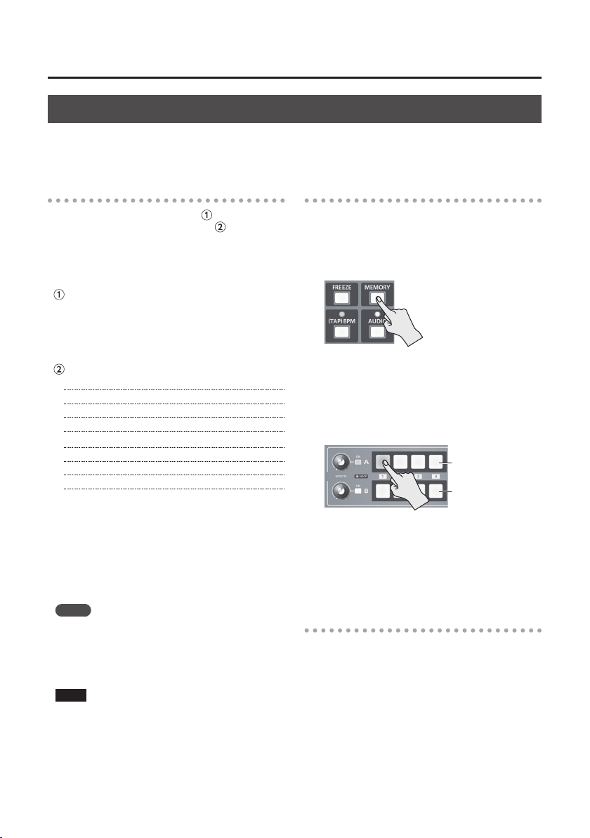
1. Press the [MEMORY] button to display the
MEMORY menu.
2. Use the [ ] and [ ] buttons to select “EFFECTS
A” or “EFFECTS B.”
3. Use the A/B fader to select the lter eect to
assign to the EFFECTS A or B [ON] button.
Value Explanation
NEGATIVE This inverts the brightness and colors.
EMBOSS This adds a bas-relief eect to the video.
COLORIZE This adds color to the video.
COLORPASS
POSTERIZE This changes the gradations in brightness.
SILHOUETTE
MONOCOLOR This produces monochrome video.
FINDEDGE This extracts contours.
FLIP This ips the video.
4. Press the [MEMORY] button to quit the menu.
This produces monochrome video with a
specic color remaining.
This separates the video into light and
dark areas, and makes the dark areas
black and adds a dierent color to the
light areas.
Applying Filter Eects
1. Output the video to which you want to apply
an eect.
2. Press the EFFECTS A or B [ON] button to turn on
the eect (lighted).
You can turn on eects separately for the output
video signals on bus A and bus B.
3. Turn the [EFFECTS A] or [EFFECTS B] knob to
adjust the degree of eect applied.
4. To turn o an eect, press the EFFECTS A or B
[ON] button a second time.
MEMO
5 You can change the eect type by holding down the
EFFECTS A [ON] button and turning the [EFFECTS A]
knob. You can change EFFECTS B as well in the same way.
Press and hold the [(TAP) BPM] button g set “EFFECTS
TYPE CHANGE” at the SETUP menu to “ON.”
21
Page 22

Video Eect Operations
A B
A B
A B
A B
A
B
A
B
A B
A B
A B
A B
A
B
A
B
A
B
A B
A B
Using Compositing Eects
These composite the bus A video and the bus B video.
NOTE
5 When compositing eects are turned on for either bus A or bus B, no eects can be applied to the other bus.
Selecting a Compositing Eect
1. Press the [MEMORY] button to display the
MEMORY menu.
2. Use the [ ] and [ ] buttons to select “EFFECTS
A” or “EFFECTS B.”
3. Use the A/B fader to select the compositing eect
to assign to the EFFECTS A or B [ON] button.
Value Explanation
WHT-L.
This makes white areas of the video transparent
KEY
and composites it onto a background video.
BLK-L.
This makes black areas of the video transparent
KEY
and composites it onto a background video.
GRN-C.
This extracts the green portions of the video
KEY
and composites it onto a background video.
BLU-C.
This extracts the blue portions of the video and
KEY
composites it onto a background video.
This composites video in an inset screen onto
PinP
a background video. The horizontal size of the
1/4
inset screen is 1/4 the width of the background
video.
This composites video in an inset screen onto
PinP
a background video. The horizontal size of the
1/2
inset screen is 1/2 the width of the background
video.
SPLIT-VSThis composites the video
stretched vertically.
SPLIT-VCThis composites the video with its
center section vertically cropped.
SPLIT-HSThis composites the video
stretched horizontally.
This composites the video with
SPLIT-
its center section horizontally
HC
cropped.
4. Press the [MEMORY] button to quit the menu.
MEMO
5 You can change the eect type by holding down the
EFFECTS A [ON] button and turning the [EFFECTS A]
knob. You can EFFECTS B as well in the same way.
Press and hold the [(TAP) BPM] button g set “EFFECT
TYPE CHANGE” at the SETUP menu to “ON.”
22
A B
A
B
A B
Compositing Using Luminance Key
This composites video with white or black areas
made transparent onto a background video.
Using luminance keying lets you superimpose logos
or text onto a background picture.
1. Follow the procedure in “Selecting a
Compositing Eect” on this page to select
“WHT-L.KEY” or “BLK-L.KEY.”
2. Press the EFFECTS A (or B) [ON] button to turn
on the eect (lighted).
3. Press the [A-1] through [A-4] and [B-1]
through [B-4] buttons to separately select
the background and the picture you want to
display in the foreground.
The video on the bus at the position where you
turned on the eect in step 2 is displayed in the
A
B
A
B
foreground.
4. Turn the [EFFECTS A] and [EFFECTS B] knobs to
adjust the amount of eect applied.
[EFFECTS A] knob
This adjusts the amount of keying for
the foreground video.
[EFFECTS B] knob
This adjusts the degree of edge blur for
the foreground video.
5. To turn o an eect, press the EFFECTS A (or B)
[ON] button a second time.
Page 23

Video Eect Operations
Compositing Using Chroma Key
This composites video shot against a blue or green
background against a dierent background video.
Blue or Green
NOTE
5 Chroma-key composition sometimes leaves color or
small artifacts at the edges of the extracted video, but
this is not a malfunction.
1. Follow the procedure in “Selecting a
Compositing Eect” (p. 22) to select “GRN-C.
KEY” or “BLU-C.KEY.”
2. Press the EFFECTS A (or B) [ON] button to turn
on the eect (lighted).
3. Press the [A-1] through [A-4] and [B-1]
through [B-4] buttons to separately select
the background and the picture you want to
display in the foreground.
The video on the bus at the position where you
turned on the eect in step 2 is displayed in the
foreground.
4. Turn the [EFFECTS A] and [EFFECTS B] knobs to
adjust the amount of eect applied.
[EFFECTS A] knob
This adjusts the amount of keying for
the foreground video.
[EFFECTS B] knob
This adjusts the degree of edge blur for
the foreground video.
Compositing Using Picture-in-Picture
This composites video in an inset screen onto a
dierent background video.
Inset screen
Background video
1. Follow the procedure in “Selecting a
Compositing Eect” (p. 22) to select “PinP 1/4”
or “PinP 1/2.”
2. Press the EFFECTS A (or B) [ON] button to turn
on the eect (lighted).
3. Use the [A-1] through [A-4] and [B-1] through
[B-4] buttons to separately select the video you
want to use as the background and as the inset
screen.
The video on the bus at the position where you
turned on the eect in step 2 becomes the inset
screen.
4. Move the A/B fader to the bus A position.
The inset screen is composited onto the
background video and the result is output.
* When the A/B fader has been moved all the way to
the bus B position, no inset screen is displayed.
5. Turn the [EFFECTS A] and [EFFECTS B] knobs to
adjust the display position of the inset screen.
[EFFECTS A] knob
This adjusts the inset screen’s display
position horizontally.
[EFFECTS B] knob
This adjusts the inset screen’s display
position vertically.
5. To turn o an eect, press the EFFECTS A (or B)
[ON] button a second time.
6. To turn o an eect, press the EFFECTS A (or B)
[ON] button a second time.
MEMO
5 You can change the width and color of the border added
to the inset screen.
Press and hold the [(TAP) BPM] button g at the SETUP
menu, make the settings for “PinP BORDER” and “PinP
BORDER COLOR.”
23
Page 24

Video Eect Operations
Compositing Using Split
This composites two video streams in a split screen.
The bus A video is displayed above or on the left, and
the bus B video is displayed below or on the right.
MEMO
5 While compositing of the video is in progress, the video
switches with cuts regardless of the selected transition
eect.
1. Follow the procedure in“Selecting a
Compositing Eect” (p. 22) to select “SPLIT-VS,”
“SPLIT-VC,” “SPLIT-HS,” or “SPLIT-HC.”
2. Press the EFFECTS A (or B) [ON] button to turn
on the eect (lighted).
3. Press one of the [A-1] through [A-4] buttons to
select the video you want to display above or
on the left.
4. Press one of the [B-1] through [B-4] buttons to
select the video you want to display below or
on the right.
5. Turn the [EFFECTS A] and [EFFECTS B] knobs to
adjust the center position.
* You can adjust this when you selected “SPLIT-HC” or
“SPLIT-VC” in step 1.
[EFFECTS A] knob
This adjusts the center position
horizontally.
[EFFECTS B] knob
This adjusts the center position
vertically.
6. To turn o an eect, press the EFFECTS A (or B)
[ON] button a second time.
24
Page 25

Audio Operations
Adjusting the Volume Level
This adjusts the volume level of input audio and output audio.
MEMO
5 You can output a test tone, which is useful for adjusting
the volume level. Press and hold the [(TAP) BPM] button
g set “TEST TONE OUTPUT” at the SETUP menu to “ON.”
1. Press the [AUDIO] button to display the AUDIO
menu.
2. Use the [ ] and [ ] buttons to select the input
audio whose volume level you want to adjust.
You use the following items to adjust the volume
level of input audio.
Menu item Explanation
HDMI IN 1–4 LEVEL
AUDIO IN LEVEL Input audio from AUDIO IN
MIC LEVEL Input audio from MIC
3. Use the A/B fader to adjust the volume level for
the respective input audio.
Input audio from respective HDMI
sources
MEMO
5 When the [AUDIO] button is illuminated, the [A-1]
through [A-4] and [B-1] through [B-3] buttons function
as shortcuts for AUDIO menu selection. You can select
audio whose volume level you want to adjust by pressing
a shortcut button.
Button AUDIO menu
[A-1]
HDMI IN 1 LEVEL
:
:
[A-4]
HDMI IN 4 LEVEL
[B-1] AUDIO IN LEVEL
[B-2] MIC LEVEL
[B-3] MASTER OUT LEVEL
5 To adjust MIC input sensitivity, you use the [MIC] knob on
the side panel.
5 The AUDIO indicator above the [AUDIO] knob lights up
as follows according to audio input and output.
Indicator Status
Lighted in
green
Lighted in
red
* By factory default, the display of the AUDIO indicator is
This lights up in green when audio input is
detected.
This lights up in red when the volume level
exceeds the maximum input/output level.
Audio output from the V-1HD might be
distorted in such cases.
set to “MASTER OUT” (output audio signal level).
If you want to use the AUDIO indicator to monitor other
audio signal, press and hold the [(TAP) BPM] button g
make the setting using “AUDIO LED” at the SETUP menu.
Raise the volume level of audio you want to
make more prominent, such as, for example,
a - microphone, and lower the volume level for
other audio.
When no audio is input, and for audio that is
unused, set the volume level to “0” (zero).
MEMO
5 Setting “MASTER OUT LEVEL” to “0” (zero) results in no
audio output from the output connectors.
4. Use the [ ] and [ ] buttons to select “MASTER
OUT LEVEL.”
5. Use the A/B fader to adjust the volume level of
output audio.
6. Press the [AUDIO] button to quit the menu.
25
Page 26

Audio Operations
Applying Eects to Audio
You can apply eects to audio that is input and output to adjust its sound quality.
Applying Eects to Input Audio
This applies eects and adjusts sound quality for
audio input via AUDIO IN, MIC, and HDMI IN.
The following table shows the eects you can use
with the dierent input audio streams.
Input audio
AUDIO IN
MIC
HDMI IN
EQ DELAY GATE COMP HPF
Eects
— — —
— — —
1. Press the [AUDIO] button to display the AUDIO
menu.
2. Use the [ ] and [ ] buttons to select the eect
menu item you want to use.
* For more information about eects, refer to the following
section.
3. Use the A/B fader to adjust the setting value.
4. Press the [AUDIO] button to quit the menu.
Equalizer (EQ)
This adjusts the sound quality for each frequency band.
Menu item Explanation
HDMI IN 1
:
HDMI IN 4
AUDIO IN
MIC
26
EQ Hi This boosts or attenuates the high band.
This adjusts the center frequency when
EQ Hi
changing the sound quality in the high
FREQ
band.
EQ Mid This boosts or attenuates the middle band.
This adjusts the center frequency when
EQ Mid
changing the sound quality in the
FREQ
middle band.
This adjusts the width of the frequency
EQ Mid
band when boosting or attenuating the
Q
middle band.
EQ Lo This boosts or attenuates the low band.
This adjusts the center frequency when
EQ Lo
changing the sound quality in the low
FREQ
band.
Delay (DELAY)
This outputs audio with a delay.
Delaying audio output lets you align the output
timing of video and audio.
Menu item Explanation
HDMI IN 1
:
HDMI IN 4
AUDIO IN
MIC
DELAY This adjusts the delay time for audio.
Compressor (COMP)
This compresses audio that exceeds a specied level.
Menu item Explanation
MIC COMP This sets the compressor on or o.
MIC COMPTHRESHOLD
MIC COMPRATIO
MIC COMPAT TACK
MIC COMPRELEASE
This sets the level used as the threshold when
compressing audio. Compression is applied to
audio that exceeds the level set here.
This species the degree of compression
applied to the audio. The state in which no
compression is applied is dened as “1.”
This sets the time until compression starts
when audio exceeding the threshold is input.
This adjusts the length of time until
compression ends after audio falls below the
threshold.
Gate (GATE)
This mutes audio that is below a specied level.
Menu item Explanation
MIC GATE This sets gate on or o.
MIC GATETHRESHOLD
MIC GATERELEASE
This sets the level used as the threshold for
removing audio. Audio below the level set
here is removed.
This adjusts the length of time until the
audio is fully attenuated after audio falls
below the threshold.
High-pass Filter (HPF)
This cuts o unneeded low-band audio. The cuto
frequency is 75 Hz.
Menu item Explanation
MIC HPF This sets the high-pass lter on or o.
Page 27

Audio Operations
Applying Eects to Output Audio
This applies eects and adjusts the sound quality for
output audio.
1. Press the [AUDIO] button to display the AUDIO
menu.
2. Use the [ ] and [ ] buttons to select the eect
menu item you want to use.
* For more information about eects, refer to the following
section.
3. Use the A/B fader to adjust the setting value.
4. Press the [AUDIO] button to quit the menu.
Equalizer (EQ)
This adjusts the sound quality for each frequency band.
Menu item Explanation
MAIN EQ Hi This boosts or attenuates the high band.
MAIN EQ Hi
FREQ
MAIN EQ Mid This boosts or attenuates the middle band.
MAIN EQ Mid
FREQ
MAIN EQ
Mid Q
MAIN EQ Lo This boosts or attenuates the low band.
MAIN EQ Lo
FREQ
This adjusts the center frequency when
changing the sound quality in the high band.
This adjusts the center frequency when
changing the sound quality in the middle band.
This adjusts the width of the frequency band
when boosting or attenuating the middle band.
This adjusts the center frequency when
changing the sound quality in the low band.
Mastering (MASTERING)
This adjusts the acoustic characteristics and tone
quality.
Menu item Explanation
MASTERING This switches mastering on and o.
MASTERING NSThis adjusts the degree of application of the
MASTERING
ENHANCER
MASTERING HiThis suppresses high-frequency distortion and
MASTERING
Mid
MASTERING LoThis suppresses low-frequency distortion and
noise suppressor.
This adjusts the degree of application of the
enhancer.
adjusts the sound to have sustained tones.
This suppresses midrange distortion and
adjusts the sound to have distinct tones.
adjusts the sound to have stable tones.
Reverb (REVERB)
This adds lingering reverberations to the audio.
You can apply reverb to audio input via AUDIO IN,
MIC, and HDMI IN.
Menu item Explanation
REVERB LEVEL
REVERB TIME This adjusts the length of the reverb.
REVERB TYPE
1. Press the [AUDIO] button to display the AUDIO
menu.
2. Use the [ ] and [ ] buttons to select “REV
SEND” for the input audio on which you want to
apply reverb.
Menu item Explanation
HDMI IN 1
:
HDMI IN 4
AUDIO IN
MIC
3. Use the A/B fader to adjust the amount of audio
sent to reverb.
Repeat steps 2 and 3 as needed to individually
adjust the amount of reverb applied.
4. Use the [ ] and [ ] buttons to select “REVERB
LEVEL.”
5. Use the A/B fader to adjust the amount of audio
returned from reverb.
This adjusts the depth of overall reverb applied
while maintaining the balance in the degree
of reverb applied to the individual input audio
streams.
6. Press the [AUDIO] button to quit the menu.
This adjusts the return level from reverb
of the audio. A setting of “0” results in no
reverb applied.
This species the type of reverb.
ROOM:
Produces the natural reverberations
of a highly resonant room.
Produces reverberations like that of
HALL:
a performance in a concert hall or
other such space.
REV SEND
This adjusts the amount of
audio sent to reverb for each
dierent input audio stream.
27
Page 28

Audio Operations
Interlinking Audio Output to Video Switching (Audio Follow)
You can associate audio with a video switch so that when the video is switched, only the HDMI audio of the
output video is output, and other HDMI audio is automatically muted.
You can also use Audio Follow with audio input via AUDIO IN or MIC.
1. Follow the procedure in “Adjusting the Volume
Level” (p. 25) to adjust the volume to the level
you want to output.
2. Press the [AUDIO] button to display the AUDIO
menu.
3. Use the [ ] and [ ] buttons to select “AUDIO
FOLLOW.”
* When the [AUDIO] button is lighted, the [B-4] button
functions as a shortcut for selecting “AUDIO FOLLOW.”
You can also select “AUDIO FOLLOW” by pressing the
[B-4] button.
4. Select the input audio to use with Audio Follow.
Value Explanation
This sets the Audio Follow feature on.
When the video is switched, only the
ON
interlinked HDMI audio of the output video is
output, and other HDMI audio is muted.
OFF This sets the Audio Follow feature o.
5. Press the [AUDIO] button to quit the menu.
6. Switch the video.
When the video input channel is switched, only
the interlinked HDMI audio of the output video
is output.
* Other settings are required to use Audio Follow with
audio input via AUDIO IN or MIC. For details, refer to
“Adding Audio Follow Associations” on this page.
Adding Audio Follow Associations
You can use Audio Follow with audio input via
AUDIO IN or MIC.
1. Press the [AUDIO] button to display the AUDIO
menu.
2. Use the [ ] and [ ] buttons to select “A.
FOLLOW AUDIO IN” or “A. FOLLOW MIC.”
Select the input audio to use with Audio Follow.
Menu item Explanation
A. FOLLOW AUDIO IN Input audio from AUDIO IN
A. FOLLOW MIC Input audio from MIC
3. Use the A/B fader to specify the video input
channel to use with Audio Follow.
Value Explanation
This sets the video input channel to interlink
1–4
with input audio using Audio Follow.
This assigns no video input channel to Audio
Follow.
OFF
Audio is always output, regardless of whether
the Audio Follow feature is on or o.
4. Press the [AUDIO] button to quit the menu.
When the Audio Follow feature is turned on,
audio input via AUDIO IN or MIC is muted on
video input channels other than the channel
specied in step 3.
28
Page 29

Other Features
Returning Settings to the Factorydefault State (Factory Reset)
You can return the values of settings on the V-1HD to
their factory defaults.
If operation that diers from what is described in
the Owner’s Manual occurs even when the steps
described are followed correctly, try performing a
factory reset.
NOTE
5 Performing a factory reset causes all settings made and
values saved in memory (p. 13) to be lost.
1. Press and hold the [(TAP) BPM] button (for 2
seconds or longer) to display the SETUP menu.
2. Use the [ ] and [ ] buttons to select “FACTORY
RESET.”
3. Move the A/B fader to the bus A position.
4. Make sure the message “PRESS “UP”” is
displayed, and press the [
(If you want to cancel the operation, move the
A/B fader to the bus B position or press the [
button.)
A factory reset is executed.
5. Press the [(TAP) BPM] button to quit the menu.
] button.
]
Operating the V-1HD by Remote Control
You can use V-1HD RCS or V-1HD Remote dedicated
software to remotely control the following functions
on the V-1HD from a computer or tablet connected
via USB.
5 V-1HD panel operations
5 Selecting transition eects
5 Audio mixer operation
5 Memory save/load operations
V-1HD RCS
V-1HD
Computer
V-1HD Remote
Tablet
V-1HD RCS and V-1HD Remote can be downloaded
from the following Roland website.
http://proav.roland.com
About Remote Control Via MIDI
The V-1HD also supports remote control by
equipment compatible with MIDI Visual Control.
For information on remote control via MIDI,
download and refer to the “V-1HD Remote Control
Guide” (PDF) from the Roland website mentioned
above.
What’s MIDI Visual Control?
MIDI Visual Control is an internationally-used
recommended practice that was added to the
MIDI specication so that visual expression could
be linked with musical performance.
Video equipment that is compatible with MIDI
Visual Control can be connected to electronic
musical instruments via MIDI in order to control
video equipment in tandem with a performance.
29
Page 30

Appendices
Troubleshooting
If you suspect a malfunction, please check the following points. If this does not resolve the problem, contact a
nearby Roland Service Center.
Problem Items to check Action Page
Video-related problems
No picture is input.
Video from the computer is
not displayed.
No picture is output.
“Snowy”-noise video is
output.
Colors are incorrect.
The edges of video shown
on the display are cut o.
Switching video is not
possible.
Compositing a logo or text
is not possible.
Audio-related Problems
No audio is output.
Audio volume is low.
No reverb is applied.
Are the [A-1] through [A-4] and [B-1]
through [B-4] buttons ashing in
white?
Is copyright-protected (HDCP) video
being input?
Is the format of the video output
from the computer compatible with
the V-1HD’s input formats?
Has the [OUTPUT FADE] knob
been turned clockwise or
counterclockwise?
Is the display connected correctly?
It is possible that the HDMI signal
is not being sent and received
correctly.
Does the color space setting on
the output-destination equipment
(external display, projector, or other
such device) match the color space
setting on the V-1HD?
Are the display settings compatible?
Is a menu (SETUP, MEMORY, or
AUDIO) displayed?
Has the eect been selected
correctly?
Is the volume turned down on
the connected amplications or
speakers?
Is the volume turned down on the
V-1HD?
Are you using connection cables
that contain resistors?
Is the amount of audio sent to
Reverb set at an appropriate level?
Video whose format diers from the [FORMAT] switch
setting is input. Input video that is compatible with
the specied format.
When inputting copyright-protected (HDCP) video
signals, go to the SETUP menu and set “HDCP” to “ON.”
The supported input formats on the V-1HD are 1080p,
1080i, and 720p. VESA-standard resolutions are not
supported.
When the [OUTPUT FADE] knob is turned clockwise or
counterclockwise, fade is applied to the main output
video.
When outputting video, adjust the [OUTPUT FADE]
knob to its center position.
When outputting copyright-protected (HDCP) video,
connect an HDCP-compatible display.
Reconnect the HDMI cable. —
Go to the SETUP menu and make the setting for
“OUTPUT COLOR SPACE” (OUTPUT connector) or
“PREVIEW COLOR SPACE” (PREVIEW connector).
Depending on the device, the color space might
be interlinked with the selection of DVI or HDMI or
the selected format. In such cases, changing the
color space on the output device might bring about
improvement for the problem.
Depending on the device, the display might
automatically overscan. Change the display’s settings.
Video-switching operations cannot be performed
while a menu is displayed. Exit the menu screen.
5 Select “WHT-L.KEY” (white) or “BLK-L.KEY” (black)
luminance key to match the background color of
the logo or text.
5 Use the to adjust the position to just the right
degree of extraction for the logo or text.
Adjust to an appropriate volume level. —
Adjust each input-audio stream to an appropriate
volume level. Also, adjust the overall volume level.
If this happens, use connector cables that do not
contain resistors.
If the send level for audio to Reverb is too low, the
amount of reverb eect might be dicult to discern.
Adjust the send level of the audio to Reverb.
p. 14
p. 15
p. 14
p. 20
p. 22
p. 25
p. 27
—
—
—
—
—
—
30
Page 31

Menu List
* The menu is shown on the monitor connected to the PREVIEW connector (p. 9).
Appendices
MEMORY Menu
Setting item Value Explanation
MEMORY1–MEMORY8
EFFECTS A
EFFECTS B
WIPE
MIX MIX, FAM, NAM, MOSAIC
TRANSFORMER A
TRANSFORMER B
TRANSFORM TIME 0.0–4.0 sec, BPM x 1/4, BPM x 1/2, BPM x 1, BPM x 2
(*1) When eects are turned on for either bus A or bus B, no eects can be applied to the other bus
(*2) For more information about transition patterns, refer to “Transition Eects List” (p. 35).
([MEMORY] button g [A-1]–[A-4] and [B-1]–[B-4] buttons)
NEGATIVE, EMBOSS, COLORIZE, COLORPASS, POSTERIZE,
SILHOUETTE, MONOCOLOR, FINDEDGE, FLIP, WHT-L.KEY(*1),
BLK-L.KEY(*1), GRN-C.KEY(*1), BLU-C.KEY(*1), PinP 1/4(*1), PinP
1/2(*1), SPLIT-VS(*1), SPLIT-VC(*1), SPLIT-HS(*1), SPLIT-HC(*1)
NEGATIVE, EMBOSS, COLORIZE, COLORPASS, POSTERIZE,
SILHOUETTE, MONOCOLOR, FINDEDGE, FLIP, WHT-L.KEY(*1),
BLK-L.KEY(*1), GRN-C.KEY(*1), BLU-C.KEY(*1), PinP 1/4(*1), PinP
1/2(*1), SPLIT-VS(*1), SPLIT-VC(*1), SPLIT-HS(*1), SPLIT-HC(*1)
H-DOWN, H-UP, V-RIGHT, V-LEFT, V-IN, V-OUT, H-IN, H- OUT, R-D OWN,
L-DOWN, R-UP, L-UP, BLOCK, V-GRID, H-GRID, H-DOWN/s, H-UP/s,
V-RIGHT/s, V-LEFT/s, H-IN/s, H-OUT/s, V-IN/s, V-OUT/s, R-DOWN/s,
L-DOWN/s, R-UP/s, L-UP/s, BLOCK/s, V-GRID/s, H-GRID/s
NONE, TRANSFORM,
MIX, CUT, EFFECTS
NONE, TRANSFORM,
MIX, CUT, EFFECTS
, , WHITE, BLACK, BPM SYNC, WIPE,
, , WHITE, BLACK, BPM SYNC, WIPE,
This species the eect assigned to the
EFFECTS A [ON] button.
This species the eect assigned to the
EFFECTS B [ON] button.
This species the transition pattern
assigned to the [WIPE] button. (*2)
* Setting values indicated with “/s” are
soft edge transition patterns.
This species the transition pattern
assigned to the [MIX] button. (*2)
This species the Function assigned to
the TRANSFORMER [
This species the Function assigned to
the TRANSFORMER [
This sets the length of time for applying
a video transition.
] button.
] button.
MEMORY 1–8 Factory-default Values
MEMORY Menu
EFFECTS A EFFECTS B WIPE MIX TRANSFORMER A TRANSFORMER B
MEMORY 1 COLORPASS FLIP V-RIGHT/s MIX
MEMORY 2 NEGATIVE COLORIZE BLOCK/s MIX
MEMORY 3 PinP 1/2 PinP 1/2 H-UP FAM TRANSFORM TRANSFORM 1.0
MEMORY 4 PinP 1/4 PinP 1/4 V-RIGHT FA M
MEMORY 5 WHT-L.KEY WHT-L.KEY H-IN/s NAM
MEMORY 6 GRN-C.KEY GRN-C.KEY V-IN/s NAM WHITE BLACK 1.0
MEMORY 7 SPLIT-VC SPLIT-HC H-GRID/s MOSAIC BPM BPM 1.0
MEMORY 8 POSTERIZE SILHOUETTE V-GRID/s MOSAIC EFFECTS EFFECTS 1.0
TRANSFORM
TIME
1.0
2.0
1.0
2.0
31
Page 32

Appendices
AUDIO Menu
* The default value is printed in bold characters.
Setting item Value Explanation
MEMORY1–MEMORY8
HDMI IN 1
:
HDMI IN 4
AUDIO IN
MIC
MASTER OUT LEVEL 0–100–127
AUDIO FOLLOW ON, OFF This sets the Audio Follow feature on or o.
HDMI IN 1
:
HDMI IN 4
AUDIO IN
MIC
MIC COMP ON, OFF This sets the compressor on or o.
MIC COMP-THRESHOLD -50 dB– -16 dB–0 dB
MIC COMP-RATIO 1.0:1–INF:1
MIC COMP-ATTACK 0.2 ms–50 ms–100 ms
MIC COMP-RELEASE 30 ms–500 ms–5000 ms
MIC GATE ON, OFF This sets gate on or o.
MIC GATE-THRESHOLD -50 dB– -36 dB–0 dB
MIC GATE-RELEASE 30 ms–800 ms–5000 ms
MIC HPF ON, OFF This sets the high-pass lter on or o.
MAIN EQ Hi -15 dB–0 dB–15 dB This boosts or attenuates the high band.
MAIN EQ Hi FREQ 700 Hz–8.00 KHz–11.0 KHz
MAIN EQ Mid -15 dB–0 dB–15 dB This boosts or attenuates the middle band.
MAIN EQ Mid FREQ 20.0 Hz–2.50 KHz–10.0 KHz
MAIN EQ Mid Q 0.5–16.0
MAIN EQ Lo -15 dB–0 dB–15 dB This boosts or attenuates the low band.
MAIN EQ Lo FREQ 55 Hz–110 Hz–800 Hz
HDMI IN 1
:
HDMI IN 4
([AUDIO] Button)
LEVEL 0–100–127
EQ Hi -15 dB–0 dB–15 dB This boosts or attenuates the high band.
EQ Hi FREQ 700 H z–8.00 KHz–11.0 KHz
EQ Mid -15 dB–0 dB–15 dB This boosts or attenuates the middle band.
EQ Mid FREQ 20.0 Hz–2.50 KHz–10.0 KHz
EQ Mid Q 0.5–16.0
EQ Lo -15 dB–0 dB–15 dB This boosts or attenuates the low band.
EQ Lo FREQ 55 Hz–110 Hz–800 Hz
DELAY 0.0 ms–500.0 ms This adjusts the delay time for audio.
REV SEND 0–100–127 This adjusts the send level of audio to Reverb.
This adjusts the volume level of the respective input audio streams.
* 100 = 0.0 dB, 127 = +6.0 dB
This adjusts the volume level of output audio.
* 100 = 0.0 dB, 127 = +6.0 dB
This adjusts the center frequency when changing the sound
quality in the high band.
This adjusts the center frequency when changing the sound
quality in the middle band.
This adjusts the width of the frequency band when boosting or
attenuating the middle band.
This adjusts the center frequency when changing the sound
quality in the low band.
This sets the level used as the threshold when compressing audio.
Compression is applied to audio that exceeds the level set here.
This species the degree of compression applied to the audio. The
state in which no compression is applied is dened as “1.”
This sets the time until compression starts when audio exceeding
the threshold is input.
This adjusts the length of time until compression ends after audio
falls below the threshold.
This sets the level used as the threshold for removing audio. Audio
below the level set here is removed.
This adjusts the length of time until the audio is fully attenuated
after audio falls below the threshold.
This adjusts the center frequency when changing the sound
quality in the high band.
This adjusts the center frequency when changing the sound
quality in the middle band.
This adjusts the width of the frequency band when boosting or
attenuating the middle band.
This adjusts the center frequency when changing the sound
quality in the low band.
32
Page 33

Appendices
Setting item Value Explanation
AUDIO IN
MIC
REVERB LEVEL 0–127
REVERB TIME 0.0 sec–1.0 sec–5.0 sec This adjusts the length of the reverb.
REVERB TYPE ROOM, HALL This species the type of reverb.
MASTERING ON, OFF This switches mastering on and o.
MASTERING NS 0–127 This adjusts the degree of application of the noise suppressor.
MASTERING ENHANCER 0–127 This adjusts the degree of application of the enhancer.
MASTERING Hi 0–127
MASTERING Mid 0–127
MASTERING Lo 0–127
A. FOLLOW AUDIO IN 1–4, OFF
A. FOLLOW MIC 1–4, OFF
REV SEND 0–100–127 This adjusts the send level of audio to Reverb.
This adjusts the return level from reverb of the audio. A setting of
“0” results in no reverb applied.
This suppresses high-frequency distortion and adjusts the sound to
have sustained tones.
This suppresses midrange distortion and adjusts the sound to have
distinct tones.
This suppresses low-frequency distortion and adjusts the sound to
have stable tones.
This sets the video channel to interlink by Audio Follow with audio
input via AUDIO IN.
* This is eective when “AUDIO FOLLOW” is set to “ON.”
This sets the video channel to interlink by Audio Follow with audio
input via MIC.
* This is eective when “AUDIO FOLLOW” is set to “ON.”
SETUP Menu
* The default value is printed in bold characters.
Setting item Value Explanation
BPM 20–120–250 This sets the tempo when the BPM sync function is turned on.
BPM SYNC x1/4, x1/2, x1, x2
HDCP ON, OFF
OUTPUT CONTRAST -64–0–63 This adjusts the contrast of the main output video.
OUTPUT SATURATION -64–0–63 This adjusts the color saturation of the main output video.
OUTPUT BRIGHTNESS -64–0–63 This adjusts the brightness of the main output video.
OUTPUT COLOR SPACE
OUTPUT DVI-D/HDMI AUTO , DVI-D, HDMI This sets the output mode of the OUTPUT connector.
PREVIEW CONTRAST -64–0–63 This adjusts the contrast of the preview output video.
PREVIEW SATURATION -64–0–63 This adjusts the color saturation of the preview output video.
PREVIEW BRIGHTNESS -64–0–63 This adjusts the brightness of the preview output video .
PREVIEW COLOR SPACE
PREVIEW DVI-D/HDMI AUTO , DVI-D, HDMI This sets the output mode of the PREVIEW connector.
PREVIEW OUT MULTI-VIEW, OUTPUT, PREVIEW This sets the view mode of preview output.
PinP BORDER 0–10–15 This adjusts the width of the border added to the PinP inset screen.
PinP BORDER COLOR
AUTO SCAN ON, OFF
AUTO SCAN TIME 0 sec–5 sec–120 sec When the Auto Scan function is on, this sets the video display interval.
(Pressing and holding the [(TAP) BPM] button for 2 seconds or longer)
When the BPM sync function is turned on, this sets the multiple of
the BPM value to be used as the speed to switch is switched.
When set to “ON,” copyright-protected (HDCP) video can be input.
HDCP is also added to the video that is output.
AUTO, RGB-FULL, RGB-LIMIT,
YPbPr
AUTO, RGB-FULL, RGB-LIMIT,
YPbPr
BLACK, WHITE, GRAY, RED, GREEN,
BLUE, YELLOW
This sets the color space (system for representing colors in video)
of the OUTPUT connector.
This sets the color space (system for representing colors in video)
of the PREVIEW connector.
This species the color of the border added to the PinP inset screen.
This sets the Auto Scan function on or o.
When set to “ON,” channels 1 through 4 are switched automatically.
33
Page 34

Appendices
Setting item Value Explanation
AUTO SCAN TRANS TIME 0.0 sec–1.0 sec–4.0 sec
A/B MODE A/B, PGM/PST This sets the operation mode for video transitions.
FREEZE MODE ALL, SELECT This sets the operation mode for freezes.
NO SIGNAL BACK BLACK, BLUE This sets the background color of channels that have no video input.
UNFIT SIGNAL BACK BLACK, BLUE, THRU
DEINTERLACE MODE WEAVE, BOB
COLOR BAR OUTPUT ON, OFF Setting this to “ON” outputs a color bar.
TEST TONE OUTPUT ON, OFF Setting this to “ON” outputs a test tone.
MIDI Rx SOURCE
MIDI OUT
MITI Tx CHANNEL
MIDI DEVICE ID
MIDI Rx CHANNEL
MIDI Rx TEMPO CLOCK
POWER ON LOAD 1–8
PGM LED
PST LED
INPUT LED ON, OFF
TRANSFORMER LED ON, OFF When set to “ON,” the TRANSFORMER buttons light up in white.
AUDIO LED
MEMORY PANEL LOAD ON, OFF
EFFECTS TYPE CHANGE ON, OFF
WIPE TYPE CHANGE ON, OFF
MIX TYPE CHANGE ON, OFF
AUTO OFF ON, OFF
FRAME RATE 59.94, 50 This sets the frame rate.
FACTORY RESET — This returns the unit to its factory defaults.
VERSION — This displays the version of the system program.
For information on remote control via MIDI, download and refer to the “V-1HD Remote Control Guide”
(PDF) from the following Roland website.
http://proav.roland.com
,
GREEN, YELLOW, BLUE,
RED
PURPLE, L.BLUE, WHITE
,
GREEN, YELLOW, BLUE,
RED
PURPLE, L.BLUE, WHITE
MASTER OUT, MIC, AUDIO IN,
HDMI 1, HDMI 2, HDMI 3, HDMI 4
When the Auto Scan function is on, this sets the length of time for
applying a video transition.
This sets the background color of channels on which video of an
incompatible format is input.
When set to “THRU,” video in an unsupported format is output
unchanged, allowing conrmation of the status of the input signal.
Note, however, that the video might contain additional noise artifacts.
This species the method used when converting interlaced input
video to progressive video.
Selecting a memory number causes the settings at the selected
memory number to be recalled at startup.
This species the color used when the output video channel
buttons ([A-1]–[A-4], [B-1]–[B-4]) light up.
This species the color used when the buttons for the video channel to
output next ([A-1]–[A-4], [B-1]–[B-4]) light up.
When set to “ON,” the [A-1]–[A-4] and [B-1]–[B-4] buttons light up,
ash, and go dark as shown below.
Button Input video status
Lighted in white Valid video is input.
Flashing in white
Dark No video is input.
This species the audio signal monitored by the AUDIO indicator.
This sets whether the state of the operation panel is updated (ON)
or not updated (OFF) when a memory is recalled.
When set to “ON,” eect assignments are changed by holding down
the EFFECTS A [ON] button and turning the [EFFECTS A] knob.
Operation for EFFECTS B is the same.
When set to “ON,” the wipe transition pattern changes with each
press of the [WIPE] button.
When set to “ON,” the mix transition pattern changes with each
press of the [MIX] button.
This sets the Auto O function on or o.
When set to “ON,” the power to the V-1HD is automatically turned
o if 240 minutes elapse with no operation performed on the unit.
Video whose format diers from the [FORMAT]
switch setting is input.
34
Page 35

Transition Eects List
MIX
Appendices
Eect Explanation
MIX
FAM
NAM
MOSAIC Transitions are made with mosaic pixelation.
As the original picture gradually disappears, the next video is overlaid and progressively
grows more visible.
Video transitions are made with the luminance levels of the two video streams maintained
unchanged.
* This is an abbreviation of “full additive mix.”
The two video streams are compared, and transitions are made with display during
transition starting with levels of high luminance.
* This is an abbreviation of “non-additive mix.”
WIPE
The original video is broken into by the next video.
Normal
H-DOWN H-UP V-RIGHT V-LEFT V-IN V-OUT H-IN H- OUT
R-DOWN L-DOWN R-UP L-UP BLOCK V-GRID H-GRID
Soft Edge
H-DOWN/s H-UP/s V-RIGHT/s V-LEFT/s V-IN/s V-OUT/s H-IN/s H-OUT/s
R-DOWN/s L-DOWN/s R-UP/s L-UP/s BLOCK/s V-GRID/s H-GRID/s
35
Page 36
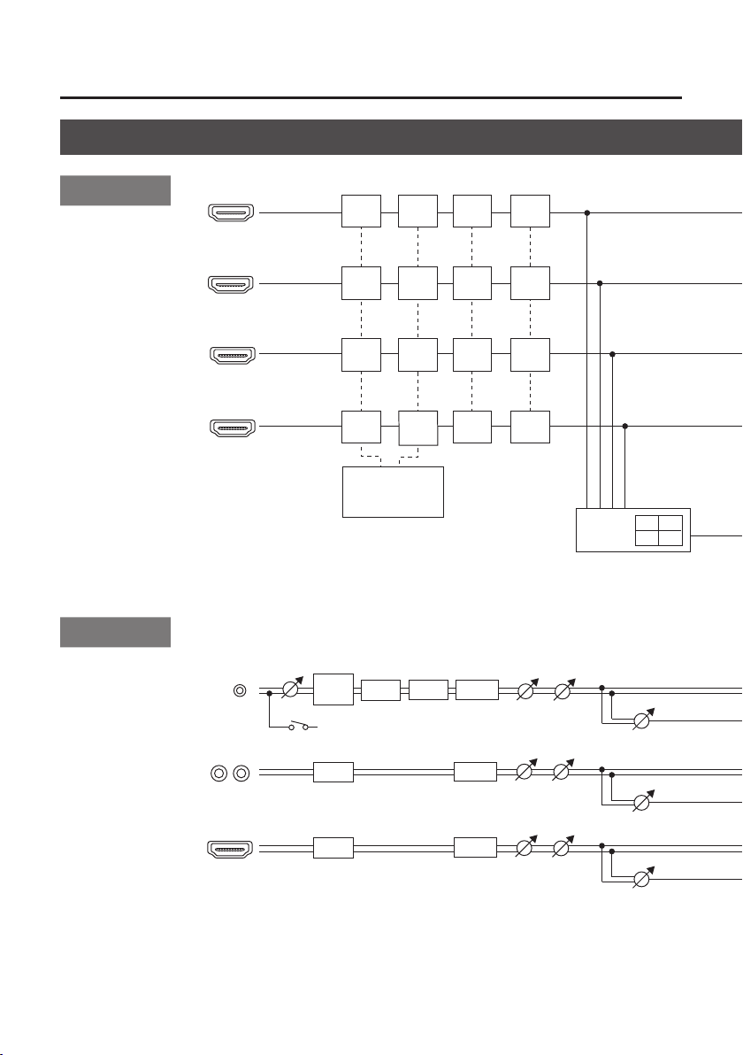
Appendices
A-BUS
B-BUS
EFFECTS B
HDMI INPUT 1
HDMI INPUT 2
EFFECTS A
1
2
3
4
INPUT
SELECT
REVERB
REVERB LEVEL
REVERB
L R
HDMI 1/2/3/4
Block Diagram
Video Block
Audio Block
HDMI INPUT 3
HDMI INPUT 4
MIC
AUDIO IN
HPF
EQ
GAIN
PLUG-IN POWER
+3.3 V
EQ
EQ
GATE
CONV
CONV
CONV
CONV
5
1080p
5
1080i
5
720p
I/P
I/P
I/P
I/P
COMP
DELAY
EDID FS
EDID FS
EDID FS
EDID FS
FORMAT
DELAY
DELAY
FREEZE
FREEZE
FREEZE
FREEZE
FOLLOW
FOLLOW
FOLLOW
LEVEL
LEVEL
LEVEL
MULTIVIEWER
1 2
3 4
REVERB SEND
REVERB SEND
REVERB SEND
36
Page 37

Appendices
REVERB
L R
HDMI PREVIEW
1
2
INPUT
SELECT
3
4
A-BUS
B-BUS
EFFECTS A
EFFECTS B
TRANSITION
5
CUT
5
MIX
5
WIPE
PGM
PST
MULTI-VIEW
OUTPUT FADE
PGM
PST
FORMAT
MENU
OSD
P/I
CONV
P/I
CONV
5
1080p
5
1080i
5
720p
HDMI OUTPUT
HDMI PREVIEW
HDMI OUTPUT
REVERB LEVEL
REVERB
MASTER LEVEL
EQ
MASTERING
AUDIO OUT
PHONES
PHONES
LEVEL
37
Page 38

Appendices
Main Specications
Video
Video Processing 4:2:2 (Y/Pb/Pr), 8-bit
Input Connectors HDMI INPUT 1–4 Type A (19 pins) x 4 * HDCP Supported
Output Connectors
Input formats HDMI
Output formats HDMI
Video Eects
Audio
Audio Processing Sampling rate 24 bits/48 kHz
Input Connectors
Output Connectors
Input Level
Input Impedance
Output Level
Output Impedance
Audio Eects EQ, Delay, Compressor, HPF, Gate, Reverb, Mastering eect
Other Connectors
USB B Type (for remote control from PC)
MIDI IN, OUT/THRU
Other Functions
MEMORY (8 types), FREEZE (input video captured), BPM SYNC (auto transition synchronized to tempo), OUTPUT FADE (WHITE/BLACK)
HDMI OUTPUT Type A (19 pins) * HDCP Supported
HDMI PREVIEW Type A (19 pins) * HDCP Supported
Transition CUT, MIX (DISSOLVE/FAM/NAM/MOSAIC), WIPE (30 types), TRANSFORMER (11 types)
EFFECTS
Digital HDMI INPUT 1–4 (19 pins) x 4
Analog
Digital
Analog
AUDIO IN -10 dBu (Maximum : +8 dBu)
MIC -41 – -13 dBu (Maximum : -1 dBu)
AUDIO IN 15 k ohms
MIC 10 k ohms
AUDIO OUT -10 dBu (Maximum : +8 dBu)
PHONES 72 mW + 72 mW (32 ohms)
AUDIO OUT 1k ohms
PHONES 10 ohms
720/59.94p, 720/50p (FORMAT switch = 720p)
1080/59.94i, 1080/50i
1080/59.94p, 1080/50p
* The input interlaced video signal is converted to progressive video signal by
internal processing.
* The video signal frame rate is selected by SETUP parameters (59.94 or 50).
720/59.94p, 720/50p (FORMAT switch = 720p)
1080/59.94i, 1080/50i (FORMAT switch = 1080i)
1080/59.94p, 1080/50p (FORMAT switch = 1080p)
* The video signal frame rate is selected in SETUP parameters (59.94 or 50).
NEGATIVE, EMBOSS, COLORIZE, COLORPASS, POSTERIZE, SILHOUETTE, MONOCOLOR,
FINDEDGE, FLIP, WH-LUMIKEY@, BK-LUMIKEY@, GR-CHROMAKEY@, BL-CHROMAKEY@,
PinP(1/4)@, PinP(1/2)@, SPLIT(H-STRETCH)@. SPLIT(H-CENTER)@, SPLIT(V-STRETCH)@,
SPLIT(V-CENTER)@
* @ marked Eects are eected common to A-BUS and B-BUS.
AUDIO IN (RCA pin type)
MIC (Stereo mini type, plug-in power supported)
HDMI OUTPUT (HDMI Type A 19 pins)
HDMI PREVIEW (HDMI Type A 19 pins)
AUDIO OUT (RCA pin type)
PHONES (Stereo mini type)
(FORMAT switch = 1080i or 1080p)
38
Page 39

Appendices
Others
Power Supply AC Adaptor
Current Draw 1.5 A
Power Consumption 18 W
Operation
Temperature
Dimensions
Weight
Accessories Owner’s Manual, AC Adaptor, Power Cord, Cord Hook
* 0 dBu=0.775 Vrms
* In the interest of product improvement, the specications and/or appearance of this unit are subject to change without prior
notice.
+0 to +40 degrees Celsius
+32 to +104 degrees Fahrenheit
313 (W) x 102 (D) x 59 (H) mm
12-1/3 (W) x 4 (D) x 2-1/3 (H) inches
1.2 kg (excluding AC adaptor)
2 lbs 10-2/5 oz
39
Page 40

Appendices
59
Dimensions
313
335
102
38
Unit: mm
40
Page 41

For the U.K.
IMPORTANT: THE WIRES IN THIS MAINS LEAD ARE COLOURED IN ACCORDANCE WITH THE FOLLOWING CODE.
For the USA
For the USA
BLUE:
BROWN:
As the colours of the wires in the mains lead of this apparatus may not correspond with the coloured markings
identifying the terminals in your plug, proceed as follows:
The wire which is coloured BLUE must be connected to the terminal which is marked with the letter N or coloured BLACK.
The wire which is coloured BROWN must be connected to the terminal which is marked with the letter L or coloured RED.
Under no circumstances must either of the above wires be connected to the earth terminal of a three pin plug.
NEUTRAL
LIVE
DECLARATION OF CONFORMITY
Compliance Information Statement
Model Name :
Type of Equipment :
Responsible Party :
Address :
Telephone :
V-1HD
HD VIDEO SWITCHER
Roland Corporation U.S.
5100 S. Eastern Avenue Los Angeles, CA 90040-2938
(323) 890-3700
FEDERAL COMMUNICATIONS COMMISSION
RADIO FREQUENCY INTERFERENCE STATEMENT
This equipment has been tested and found to comply with the limits for a Class B digital device, pursuant to Part 15 of
the FCC Rules. These limits are designed to provide reasonable protection against harmful interference in a residential
installation. This equipment generates, uses, and can radiate radio frequency energy and, if not installed and used in
accordance with the instructions, may cause harmful interference to radio communications. However, there is no
guarantee that interference will not occur in a particular installation. If this equipment does cause harmful interference
to radio or television reception, which can be determined by turning the equipment o and on, the user is encouraged
to try to correct the interference by one or more of the following measures:
– Reorient or relocate the receiving antenna.
– Increase the separation between the equipment and receiver.
– Connect the equipment into an outlet on a circuit dierent from that to which the receiver is connected.
– Consult the dealer or an experienced radio/TV technician for help.
This device complies with Part 15 of the FCC Rules. Operation is subject to the following two conditions:
(1) this device may not cause harmful interference, and
(2) this device must accept any interference received, including interference that may cause undesired operation.
This equipment requires shielded interface cables in order to meet FCC class B limit.
Any unauthorized changes or modications not expressly approved by the party responsible for compliance could void
the user’s authority to
CAN ICES-3 (B)/NMB-3 (B)
operate the equipment.
For Canada
For Korea
For C.A. US (Proposition 65)
WARNING
This product contains chemicals known to cause cancer, birth defects and other reproductive harm, including lead.
41
Page 42

For EU Countries
For China
42
Page 43

Intellectual Property Right
• It is forbidden by law to make an audio recording,
video recording, copy or revision of a third party’s
copyrighted work (musical work, video work, broadcast,
live performance, or other work), whether in whole or in
part, and distribute, sell, lease, perform or broadcast it
without the permission of the copyright owner.
• Do not use this product for purposes that could
infringe on a copyright held by a third party. We
assume no responsibility whatsoever with regard to any
infringements of third-party copyrights arising through
your use of this product.
• This product can be used to record or duplicate audio
or visual material without being limited by certain
technological copy-protection measures. This is due to
the fact that this product is intended to be used for the
purpose of producing original music or video material,
and is therefore designed so that material that does not
infringe copyrights belonging to others (for example,
your own original works) can be recorded or duplicated
freely.
• MMP (Moore Microprocessor Portfolio) refers to a
patent portfolio concerned with microprocessor
architecture, which was developed by Technology
Properties Limited (TPL). Roland has licensed this
technology from the TPL Group.
• This product contains eParts integrated software
platform of eSOL Co.,Ltd. eParts is a trademark of eSOL
Co., Ltd. in Japan.
• Roland is an either registered trademark or trademark
of Roland Corporation in the United States and/or other
countries.
• Company names and product names appearing in this
document are registered trademarks or trademarks of
their respective owners.
43
Page 44

* 5 1 0 0 0 4 8 9 9 7 - 0 2 *
 Loading...