

Roland V-160HD User Manual
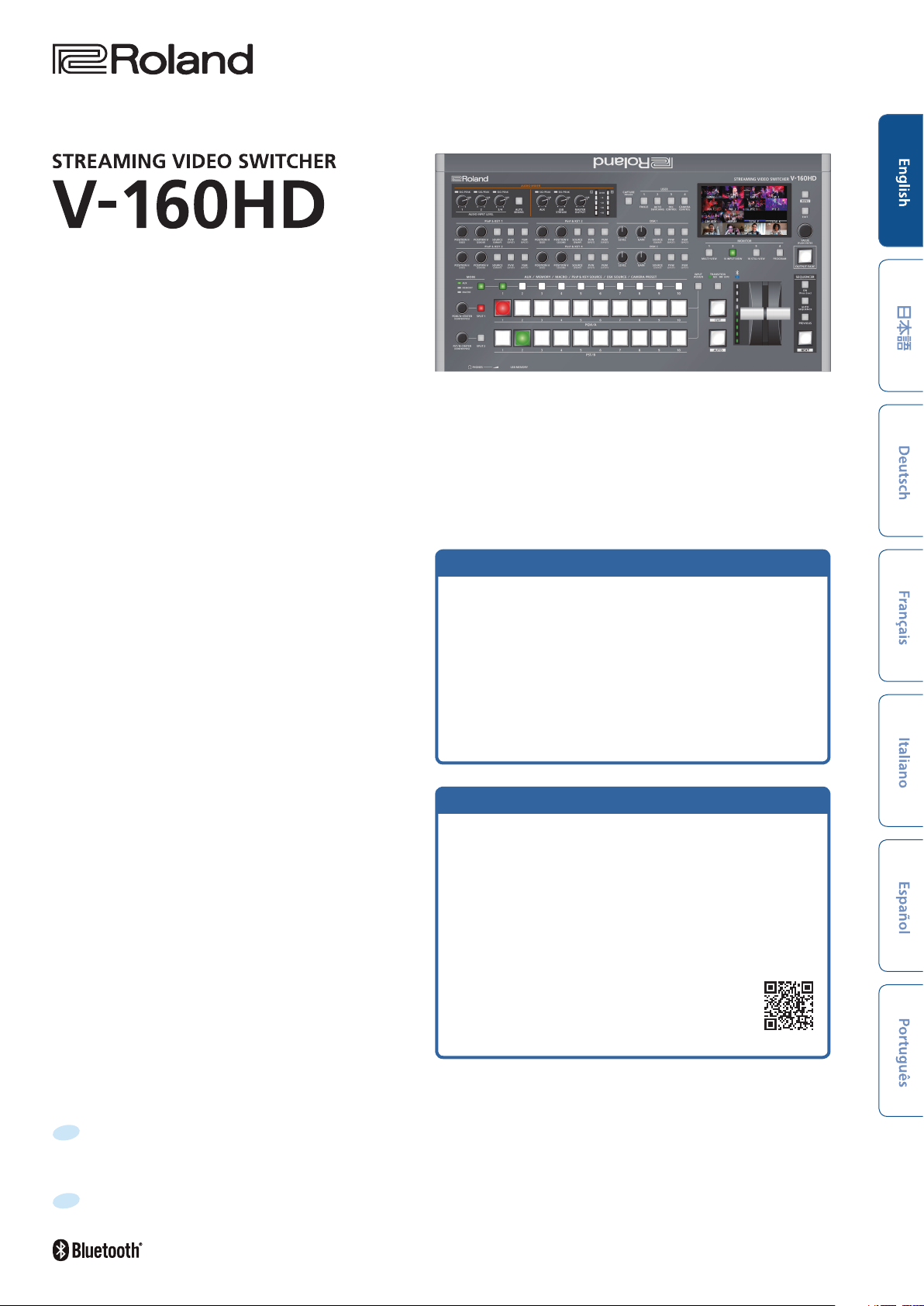
Startup Guide
Checking the Included Items
Check that all of the included items are present. If any of the
included items are missing, contact your dealer.
 V-160HD unit
 AC adaptor
 Power cord
 Rack-mount angle (2)
PDF Manual
Á Reference Manual
Contains more detailed explanations on operating this unit, a list
of menus and more.
Á Remote Control Guide
Contains a reference of RS-232 commands, MIDI implementation
and other information.
(download from the Web)
Downloading
1. Enter the following URL in your computer.
https://proav.roland.com/manuals/
 Rack-mount angle mounting screws (6)
 Startup Guide (this document)
 Leaet “USING THE UNIT SAFELY”
2. Choose “V-160HD” as the product name.
Before using the unit, ensure that its system program is at the most recent version. For information on available upgrades for the system program, see
the Roland website (https://proav.roland.com/).
You can check the system program version by Pressing the [MENU] button
Before using this unit, carefully read “USING THE UNIT SAFELY” and “IMPORTANT NOTES” (the leaet “USING THE UNIT SAFELY” and the Startup Guide
(p. 12)). After reading, keep the document(s) where it will be available for immediate reference.
“SYSTEM” Ó “VERSION.”
Ó
© 2021 Roland Corporation

Panel Descriptions
Top Panel
1
4
6 7
8
10
11
2
3
19
5
17
20
21
18
22
15
13
12
16
23
9
1
AUDIO MIXER
SIG/PEAK indicators (1, 2, 3/4)
These are lit green when audio input is detected. If the input is
excessive, the indicator is lit red.
AUDIO INPUT LEVEL [1] [2] [3/4] knobs
Adjust the volume of the AUDIO IN 1, 2, or 3/4.
[AUTO MIXING] button
Turns the auto-mixing function (used to automatically control the
volume) on/o.
SIG/PEAK indicators (AUX, USB STREAM)
Shows the volume level for the AUX bus and USB output.
When the output level exceeds -50 dB, this lights up green. This
lights up red when the output is excessive (0 dB or higher).
[AUX] knob
Adjusts the volume of the AUX bus output.
[USB STREAM] knob
Adjusts the volume of the USB output.
[MASTER OUTPUT] knob
Adjusts the overall volume.
14
3
USER [1]–[4] buttons
These buttons execute pre-assigned functions.
With the factory settings, the following functions are assigned.
Button Explanation
USER [1]
USER [2]
USER [3]
USER [4]
4
PinP & KEY 1–4
This uses PinP and KEY 1–4 layers to composite video using PinP,
or picture-in-picture (p. 9).
[POSITION H] knob
Adjusts the horizontal position of the inset screen.
By turning the knob while pressing it, you can adjusts the size of
the inset screen.
FREEZE
Turns the freeze function (freeze the input video) on/o.
AUTO SWITCHING
Turns the auto switching function (used to automatically
switch between videos) on/o.
REC CONTROL
Controls the recorder’s video record start/stop if a recorder
that supports REC control functionality is connected.
CAMERA CONTROL
Turns the camera control on/o.
When this is on (lit), the
buttons are used to recall the presets.
7
CAMERA PRESET [1]–[10]
Level meter
Indicates the volume level of the overall output.
2
[CAPTURE IMAGE] button
Turns the still image capture mode on/o.
2
[POSITION V] knob
Adjusts the vertical position of the inset screen.
By turning the knob while pressing it, you can adjust the zoom of
the video shown in the inset screen.
[SOURCE] button
When this is on (lit), you can select the video source for the inset
screens using the 7 PinP & KEY SOURCE [1]–[10] buttons.
[PVW] button
Turns the inset screen preview output on/o.
[PGM] button
Turns PinP composition on/o.
5
DSK 1, 2
This uses DSK layer 1 or 2 to composite video using a downstream
keyer (p. 10).
[LEVEL] knob
Adjusts the degree of extraction (transparency) for the key.
[GAIN] knob
Adjusts the degree of edge blur (semi-transmissive region) for the
key.
[SOURCE] button
When this is on (lit), you can select the DSK video source using the
7
PinP & KEY SOURCE [1]–[10] buttons.
[PVW] button
Turns the preview output of the DSK compositing result on/o.
[PGM] button
This switches DSK composition on or o.
6
[MODE] button
7
Switches the functioning of the AUX / MEMORY / MACRO [1]–
[10] buttons. An indicator located at the left of the [MODE] button
is lit to indicate the current function.
7
AUX / MEMORY / MACRO / PinP & KEY SOURCE /
DSK SOURCE / CAMERA PRESET [1]–[10] buttons
The functions of these buttons change as shown in the table
below.
When button is lit Functions of buttons [1]–[10]
AUX
Select the video that is sent to the AUX bus.
MEMORY
Recalls the preset memory (the video/audio
[MODE]
PinP & KEY 1–4
[SOURCE]
DSK 1, 2 [SOURCE]
USER [4]
(CAMERA CONTROL)
8
[PGM/A-CENTER] [PST/B-CENTER] knobs
Adjust the split compositing settings (p. 8).
Knob Explanation
[PGM/A-CENTER]
[PST/B-CENTER]
and other data that is saved). Long-press a
button to save the current settings in a preset
memory.
MACRO
Executes a macro (a series of recorded
operations).
PinP & KEY SOURCE
Select the video source for the inset screen
(p. 9).
DSK SOURCE
Selects the DSK video source (p. 10).
CAMERA PRESET
Recalls the registered preset (camera position,
focus settings, etc.) from the connected camera.
Adjusts the horizontal/vertical position of the
video that’s shown in the left or upper area.
Turn while pressing:
Adjusts the position of the boundary.
Adjusts the horizontal/vertical position of the
video that’s shown in the right or lower area.
Turn while pressing:
Adjusts the position of the boundary.
Panel Descriptions
9
[SPLIT 1] [SPLIT 2] buttons
Turns on/o video compositing using split (p. 8).
10
PGM/A cross-point [1]–[10] buttons
Selects the video to input to bus PGM/A. The selected button
lights up.
11
PST/B cross-point [1]–[10] buttons
Selects the video to input to bus PST/B. The selected button lights
up.
12
[INPUT ASSIGN] button
Press a cross-point button while holding down the [INPUT
ASSIGN] button to change the video source for the buttons you
pressed.
The video source changes in the following order each time you
press the button.
¹ [INPUT ASSIGN] + PGM/A cross-point buttons
STILL 16 Ó 1
¹ [INPUT ASSIGN] + PST/B cross-point buttons
HDMI 1
Ó 8
13
[TRANSITION] button
Selects the video transition eects (MIX, WIPE).
The MIX or WIPE indicator lights to show that it is selected.
14
[CUT] [AUTO] button
Automatically switch between the videos being input to bus
PGM/A and PST/B, and send them to the nal output.
Button Explanation
[CUT] The picture switches instantly.
[AUTO]
15
(Bluetooth®) indicator
Shows the Bluetooth connection status.
Lit Connected Rapid blinking Now pairing
Unlit Bluetooth o Blinking Waiting for connection
You can input audio from an audio device that uses Bluetooth,
or use dedicated software on your computer or iPad to remotely
control the V-160HD.
16
Video fader
Manually switch between the videos being input to bus PGM/A
and PST/B, and send them to the nal output.
A transition eect is applied and the video is switched
automatically.
Transition indicator
The indicators light up to show the video fader position.
When the video fader is pushed all the way down, only the
topmost or bottommost transition indicator lights.
17
Monitor
Shows the input/output video, a loaded still image, or a menu.
* The same video as that shown on the monitor of this unit is output
from the HDMI OUT 3 connector.
Ó
Ó
SDI 8 Ó 1
SDI 1
Ó 8
Ó
Ó
HDMI 8 Ó 1
STILL 1
Ó 16
3
Panel Descriptions
18
MONITOR [1]–[4] buttons
Switches between the video to monitor. Both the display from the
monitor of this unit and the output video from the HDMI OUT 3
connector switch at the same time.
Button Explanation
MULTI-VIEW
MONITOR [1]
MONITOR [2]
MONITOR [3]
MONITOR [4]
* The settings described above are the factory defaults. You can also
assign dierent video to each button.
19
[MENU] button
Switches the menu between visible and hidden.
The menu appears on the built-in monitor and the display
connected to the HDMI OUT 3 connector.
The nal output video, preview output video and the
videos allocated to the cross-point [1]–[8] buttons
are shown in sections of the display.
16 INPUT-VIEW
The input video from the HDMI IN connectors and
the SDI IN connectors are shown as 16 separate
sections on the screen.
16 STILL-VIEW
Shows the loaded still images in 16 separate sections
on the screen.
PROGRAM
Shows the nal output video.
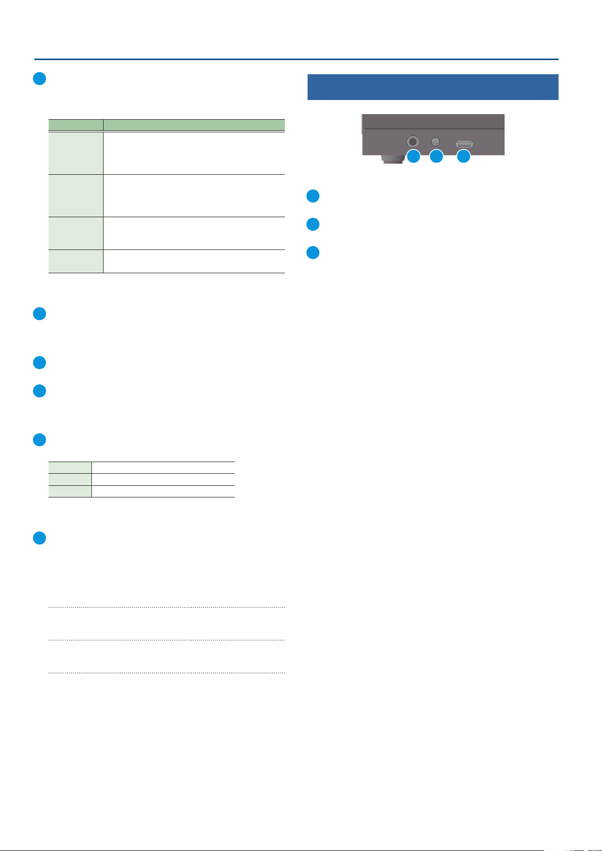
Front Panel
1 2 3
1
PHONES jack
Connect headphones.
2
[PHONES] knob
Adjusts the volume of the headphones.
3
USB MEMORY port
Connect a USB ash drive. Use this to save/load the settings of this
unit, and to load still images.
* Never turn o the power or remove the USB ash drive while the USB
ash drive is being accessed.
20
[EXIT] button
Returns you to the menu one level higher.
21
[VALUE] knob
Selects a menu item, or edits the value of a setting.
Press this knob to conrm the menu item you selected or the
value that you edited.
22
[OUTPUT FADE] button
The nal output video and audio fade in/out.
Lit Fade-out completed
Blinking Now fading-in/out
Unlit Normal output
* The settings described above are the factory defaults. You can also
assign other functions to the [OUTPUT FADE] button.
23
SEQUENCER
Use this to execute operations such as macros or recalling
preset memories (sequence function) in the order that you have
specied beforehand.
[ON] button
Long-press to turn sequence mode on/o.
[AUTO SEQUENCE] button
Turns the auto sequence function on/o.
[PREVIOUS] button
Returns to the previous operation.
[NEXT] button
Advances to the next operation. The button blinks while the
operation is executing.
4
 Loading...