

Page 1
Reference Manual
Use the “V-02HD Utility” dedicated software to back up and restore settings
You can use the “V-02HD Utility” dedicated software to back up the
settings of the V-02HD to a USB-connected computer, and restore
backed-up settings when needed.
5 You can download “V-02HD Utility” from the Roland website (https://proav.
roland.com/)
Use the “V-02HD Remote” iPad app to remotely control the V-02HD unit.
You can connect the V-02HD to your iPad via USB, and remotely control
the V-02HD unit from the “V-02HD Remote” iPad app.
5 You can download the app from the App Store at no cost.
5 The app is supported by the V-02HD’s system program version 1.1 and later.
Contents
Operating Guide (Panel Description) . . . . . . . . . . . . . . . . . . . 2
Front Panel . . . . . . . . . . . . . . . . . . . . . . . . . . . . . . . . . . . . . . . . . . 2
Rear Panel . . . . . . . . . . . . . . . . . . . . . . . . . . . . . . . . . . . . . . . . . . . 4
Connecting a Footswitch . . . . . . . . . . . . . . . . . . . . . . . . . . . . 6
Basic Operations . . . . . . . . . . . . . . . . . . . . . . . . . . . . . . . . . . . . . . 7
Turning the Power On/O . . . . . . . . . . . . . . . . . . . . . . . . . . . . . 7
Operating the Menu . . . . . . . . . . . . . . . . . . . . . . . . . . . . . . . . . . 7
Video Input/Output Settings. . . . . . . . . . . . . . . . . . . . . . . . . . . 8
List of Compatible Video Formats . . . . . . . . . . . . . . . . . . . . . . . 8
Setting the Output Format. . . . . . . . . . . . . . . . . . . . . . . . . . . . . 8
Specifying the Input Format (EDID) . . . . . . . . . . . . . . . . . . . . . 9
Adjusting Output Video . . . . . . . . . . . . . . . . . . . . . . . . . . . . . . . 9
Adjusting the Input Video. . . . . . . . . . . . . . . . . . . . . . . . . . . . . . 10
Outputting the Program Video from
the PREVIEW OUT Connector . . . 10
Inputting Copy-Protected (HDCP) Video . . . . . . . . . . . . . . . . . 11
Video Operations. . . . . . . . . . . . . . . . . . . . . . . . . . . . . . . . . . . . . . 12
Using Mix/Wipe to Switch Video (MIX/WIPE) . . . . . . . . . . . . . 12
Using Picture-In-Picture to Composite Video (PinP) . . . . . . . 13
Using a Key to Composite Video (KEY) . . . . . . . . . . . . . . . . . . . 14
Compositing a Logo or Image (Luminance Key) . . . . . . . . 14
Compositing a Subject and Background (Chroma Key) . . 16
Applying a Visual Eect to the Video (VFX) . . . . . . . . . . . . . . . 18
Applying a Fade to the Program Output Video
(Output Fade) . . . . . . 19
Using a Captured Still Image . . . . . . . . . . . . . . . . . . . . . . . . . . . 20
Audio Operations . . . . . . . . . . . . . . . . . . . . . . . . . . . . . . . . . . . . . 22
Adjusting the Volume Level . . . . . . . . . . . . . . . . . . . . . . . . . . . . 22
Applying Eects to Input Audio . . . . . . . . . . . . . . . . . . . . . . . . 23
Applying Eects to Output Audio. . . . . . . . . . . . . . . . . . . . . . . 24
Silencing Only Specic Audio (Mute) . . . . . . . . . . . . . . . . . . . . 24
Interlinking Audio Output to Video Switching
(Audio Follow). . . . . . 25
Other Features . . . . . . . . . . . . . . . . . . . . . . . . . . . . . . . . . . . . . . . . 26
Saving/Recalling Settings (Preset Memory) . . . . . . . . . . . . . . 26
Using a Footswitch. . . . . . . . . . . . . . . . . . . . . . . . . . . . . . . . . . . . 27
Using an Expression Pedal . . . . . . . . . . . . . . . . . . . . . . . . . . . . . 28
Preventing Unintended Operation (Panel Lock). . . . . . . . . . . 29
Returning to the Factory Settings (Factory Reset) . . . . . . . . . 29
Menu List . . . . . . . . . . . . . . . . . . . . . . . . . . . . . . . . . . . . . . . . . . . . . 30
1: VIDEO INPUT . . . . . . . . . . . . . . . . . . . . . . . . . . . . . . . . . . . . . . . 30
2: VIDEO OUTPUT . . . . . . . . . . . . . . . . . . . . . . . . . . . . . . . . . . . . . 31
3: TRANSITION TIME . . . . . . . . . . . . . . . . . . . . . . . . . . . . . . . . . . . 32
4: MIX/WIPE . . . . . . . . . . . . . . . . . . . . . . . . . . . . . . . . . . . . . . . . . . 32
5: PinP. . . . . . . . . . . . . . . . . . . . . . . . . . . . . . . . . . . . . . . . . . . . . . . 32
6: KEY . . . . . . . . . . . . . . . . . . . . . . . . . . . . . . . . . . . . . . . . . . . . . . . 33
7: VFX . . . . . . . . . . . . . . . . . . . . . . . . . . . . . . . . . . . . . . . . . . . . . . . 34
8: AUDIO INPUT . . . . . . . . . . . . . . . . . . . . . . . . . . . . . . . . . . . . . . 36
9: AUDIO OUTPUT . . . . . . . . . . . . . . . . . . . . . . . . . . . . . . . . . . . . 38
10: AUDIO FOLLOW . . . . . . . . . . . . . . . . . . . . . . . . . . . . . . . . . . . 39
11: PRESET MEMORY . . . . . . . . . . . . . . . . . . . . . . . . . . . . . . . . . . 39
12: CTL/EXP . . . . . . . . . . . . . . . . . . . . . . . . . . . . . . . . . . . . . . . . . . 40
13: CAPTURE IMAGE. . . . . . . . . . . . . . . . . . . . . . . . . . . . . . . . . . . 41
14: SYSTEM . . . . . . . . . . . . . . . . . . . . . . . . . . . . . . . . . . . . . . . . . . 41
MIDI Implementation. . . . . . . . . . . . . . . . . . . . . . . . . . . . . . . . . . 43
Appendix . . . . . . . . . . . . . . . . . . . . . . . . . . . . . . . . . . . . . . . . . . . . . 55
Troubleshooting. . . . . . . . . . . . . . . . . . . . . . . . . . . . . . . . . . . . . . 55
Block Diagram. . . . . . . . . . . . . . . . . . . . . . . . . . . . . . . . . . . . . . . . 57
Main Specications . . . . . . . . . . . . . . . . . . . . . . . . . . . . . . . . . . . 58
Dimensions . . . . . . . . . . . . . . . . . . . . . . . . . . . . . . . . . . . . . . . . . . 59
© 2018 Roland Corporation
Page 2
Operating Guide (Panel Description)
Front Panel
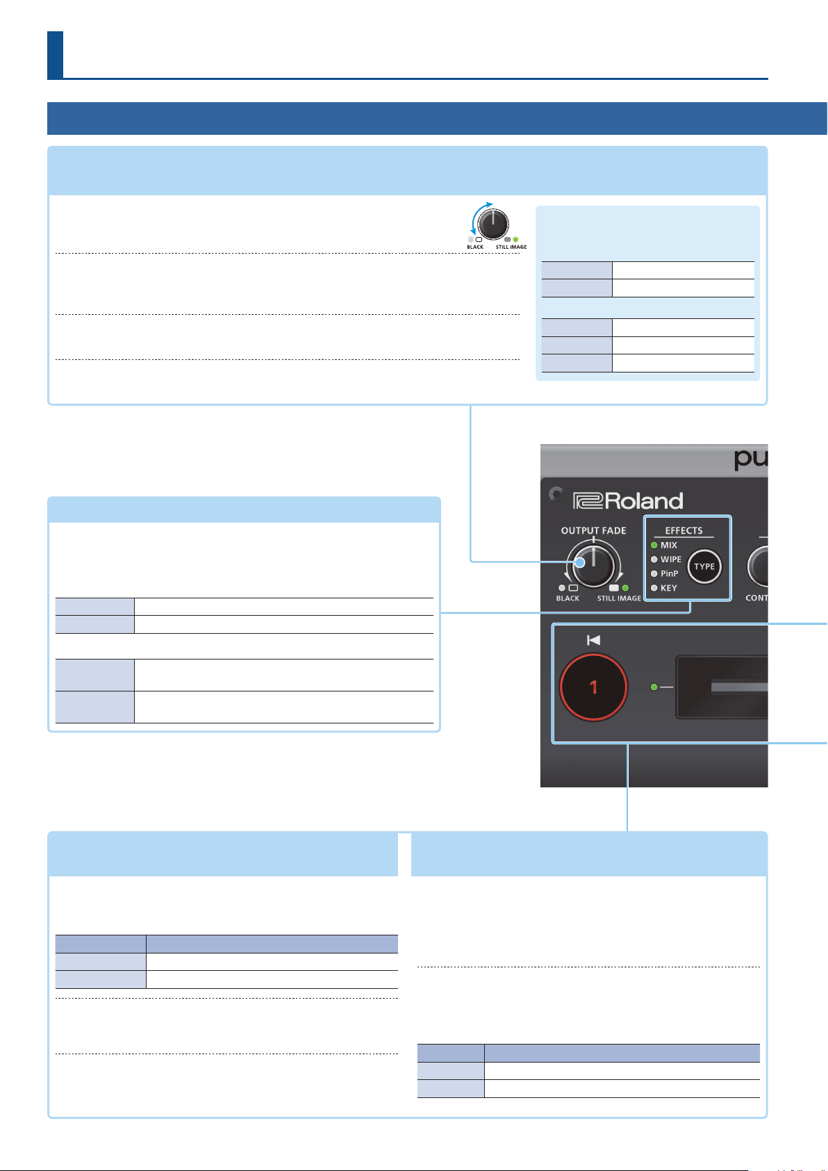
9 Fading video and audio in or out
9 Outputting a captured still image
Turn counterclockwise from the center
The program output video and audio fade in/out simultaneously.
(p. 19)
(p. 20)
Fade-in
Fade-out
The video fades to a black screen.
Turn clockwise from the center
If you turn the knob all the way clockwise, the captured still image is output to
preview/program as a cut (instant switching).
Center
Normal output.
5 The settings described above are the factory defaults. You can also assign other functions to
the [OUTPUT FADE] knob.
9 Selecting a Video Eect
[TYPE] button
You can select the eect that’s applied to the video. The video eect
is switched each time you press the button. The indicator of the
selected video eect is lit.
[OUTPUT FADE] knob
The indicators located at the left and right
of the [OUTPUT FADE] knob show the status.
Left indicator
Blinking red Fading in/out
Lit red Fade-out completed
Right indicator
Lit green Unit contains still image
Lit red Still image is being output
Dark Unit contains no still image
Transition eects (p. 12)
MIX The two videos are mixed as the transition occurs.
WIPE The next video moves across to replace the original video.
Composition eects (p. 13, 14, 16)
Picture-inpicture (PinP)
KEY
9 Switching video
[1] [2] buttons, Video fader
The inset screen (a separate small screen) is shown on top
of the background video.
A portion of the video is made transparent, and composited
with the background video.
(p. 12)
[1] [2] buttons
Switch between the videos being input to INPUT 1 and 2, and
send them to the program output.
[1] [2] buttons Status
Lit red Program output video
Lit green Preview output video (standby video)
Video fader
Manually switch between the videos being input to INPUT 1
and 2, and send them to the program output.
Transition indicators
(both sides of the fader)
The lit indicator shows the video that is being output as the
program.
9 Compositing video
[1] [2] buttons, Video fader
(p. 13, 14, 16)
[1] button (Lit yellow)/
Transition indicators (both sides of the fader)
Selects the background video when compositing video. A
transition indicator (left or right) is lit to indicate the selected
background video.
[2] button/Video fader
Outputs the resulting composited video as the program. The
inset screen of picture-in-picture or the key video or image for
key compositing is revealed or removed.
[2] button Status
Lit red Outputting the composited result as the program
Dark Outputting only the background video as the program
2
Page 3
Operating Guide (Panel Description)
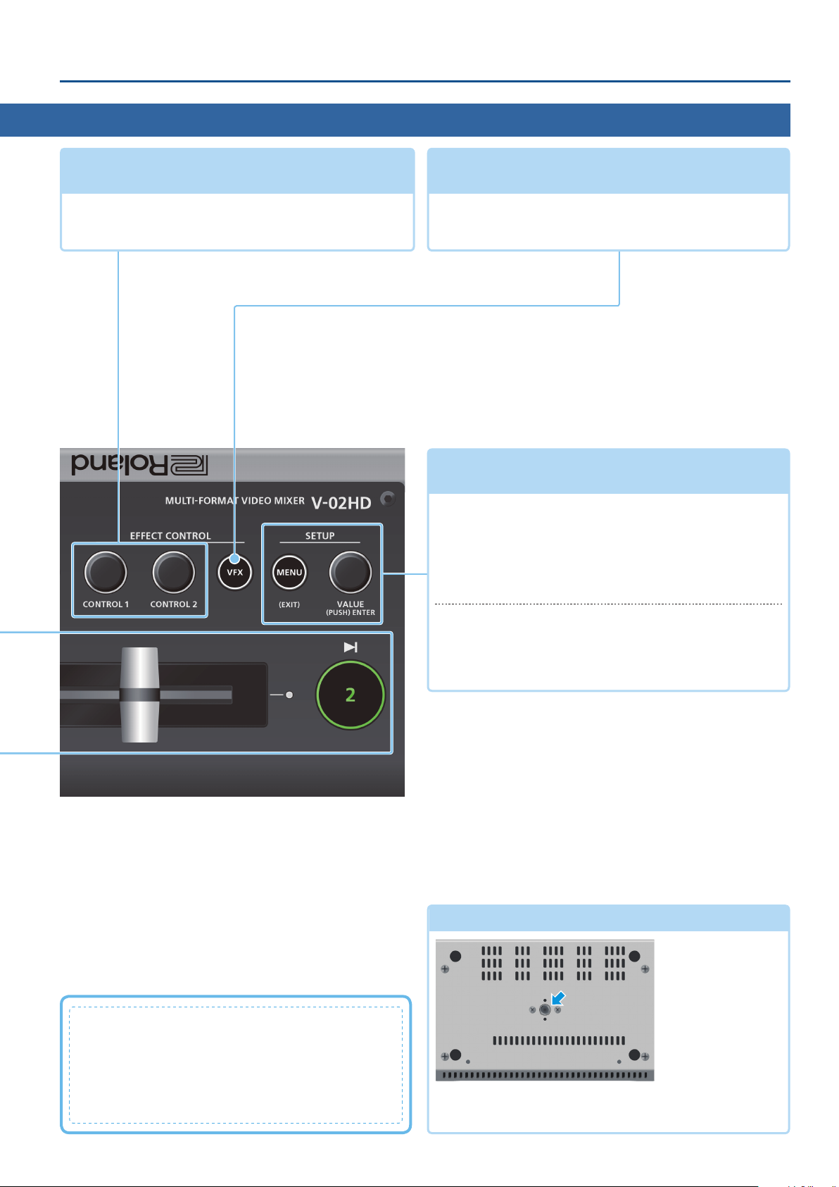
9 Adjusting the video eect
[CONTROL 1] [CONTROL 2] knobs
These adjust the video eect or visual eect (VFX).
5 If the visual eect is on ([VFX] button lit), these knobs control the
visual eect.
(p. 12–18)
9 Applying a Visual Eect to the Video
[VFX] button
Turns the visual eect on/o.
When on, the [VFX] button is lit.
9 Operating the Menu
[MENU] button, [VALUE] knob
[MENU] button
Turning this button on (lit) makes a menu appear on the
display that is connected to the PREVIEW OUT connector.
If you’ve moved to a lower-level item of the menu, this button
returns you to the next higher level. If the highest menu level
is already shown, the button closes the menu.
(p. 7)
(p. 18)
What is the program output?
This is the video output that reects all processing such
as video compositing and visual eects. It is output from
the PROGRAM OUT connector.
This is the video that is seen by the people who are
watching the live stream or presentation.
[VALUE] knob
Turning: This selects a menu item or changes a setting value.
Pressing: This accepts the selected menu item or applies
changes to a setting.
Tripod mounting socket
This is used when attaching the V-02HD to a commercially
available camera tripod. The socket is threaded for a 1/4” screw.
(bottom panel)
3
Page 4
Operating Guide (Panel Description)
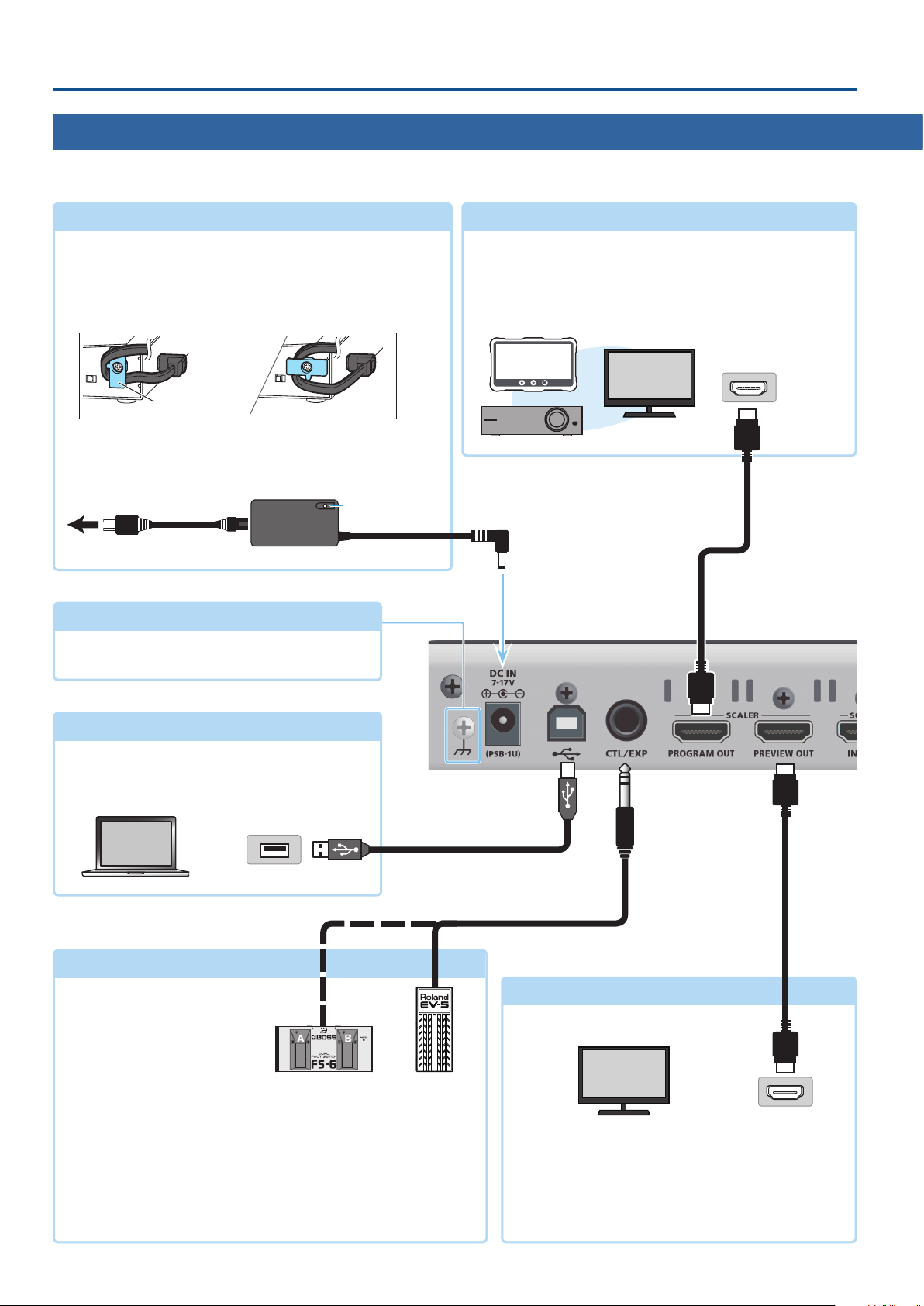
Rear Panel
* To prevent malfunction and equipment failure, always turn down the volume, and turn o all the units before making any connections.
DC IN jack
Connect the included AC adaptor to this jack.
* Use the cord hook to secure the cord of the AC adaptor as shown
in the illustration.
For information on how to attach the cord hook, refer to
“Attaching the Cord Hook” (p. 5).
Cord hook
* Place the AC adaptor so the side with the indicator (see
illustration) faces upwards and the side with textual information
faces downwards. The indicator will light when you plug the AC
adaptor into an AC outlet.
Indicator
to an AC outlet
Power cord
AC adaptor
Ground terminal
Connect this to an external earth or ground if
necessary.
PROGRAM OUT connector
This outputs the resulting mixed video (the program video).
Here you can connect a display, projector, or video recorder
that is equipped with an HDMI input connector.
HDMI input
connector
HDMI cable
USB ( O ) port
Connect your computer here. This is used when
backing up the unit’s settings, or when updating
the system program.
USB2.0 cable
USB 2.0 port
CTL/EXP jack
(TRS phone)
Connect an expression pedal (sold separately: EV-5, etc.) or
footswitch (sold separately: BOSS FS-6, etc.). This is used when using
your foot to control operations such as video switching.
For details on connecting a footswitch, refer to “Connecting a
Footswitch” (p. 6).
* Use only the specied expression pedal (EV-5, BOSS FV-500L, or FV-500H
sold separately). By connecting any other expression pedals, you risk
causing malfunction and/or damage to the unit.
HDMI cable
PREVIEW OUT connector
HDMI input
connector
This outputs the preview video (the standby video).
Connect this to a display that is equipped with an
HDMI input connector.
5 The V-02HD menu is shown on the display that’s connected
to the PREVIEW OUT connector.
4
Page 5
Operating Guide (Panel Description)
* Do not block the ventilation openings (the slits located on the front and side panels, etc.). If the ventilation openings are blocked, the internal
temperatures may rise, causing malfunctions due to excessive heat.
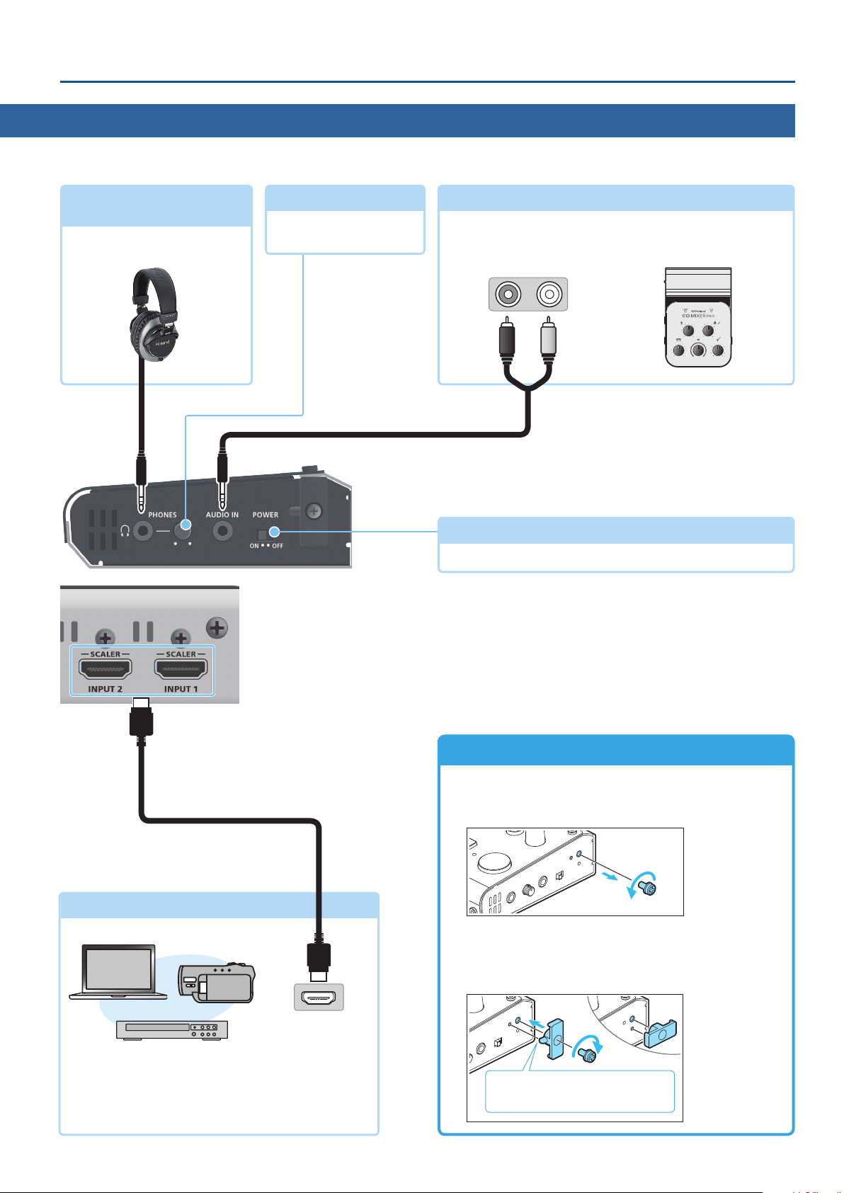
PHONES ( Q ) jack
(stereo mini)
Connect headphones here.
[PHONES] knob
Adjusts the volume of the
headphones.
AUDIO IN jack
This inputs audio. Connect this to your audio or video device
such as an audio mixer or CD player.
Audio output connectors
9 Turning the Power On/O (p. 7)
This switch turns the power on/o.
(stereo mini)
[POWER] switch
HDMI cable
INPUT 1, 2 connectors
HDMI output
connector
These input video. Connect these to a video camera,
video device such as a BD player, or a computer that is
equipped with an HDMI output connector.
Attaching the Cord Hook
Attach the included cord hook.
1. Remove the screw (one) indicated in the illustration.
2. Using the screw that you removed in step 1, attach the
cord hook as shown in the illustration.
You can attach the cord hook either vertically or horizontally.
Align the protruding portion of the
cord hook with the hole in the unit.
5
Page 6
Operating Guide (Panel Description)
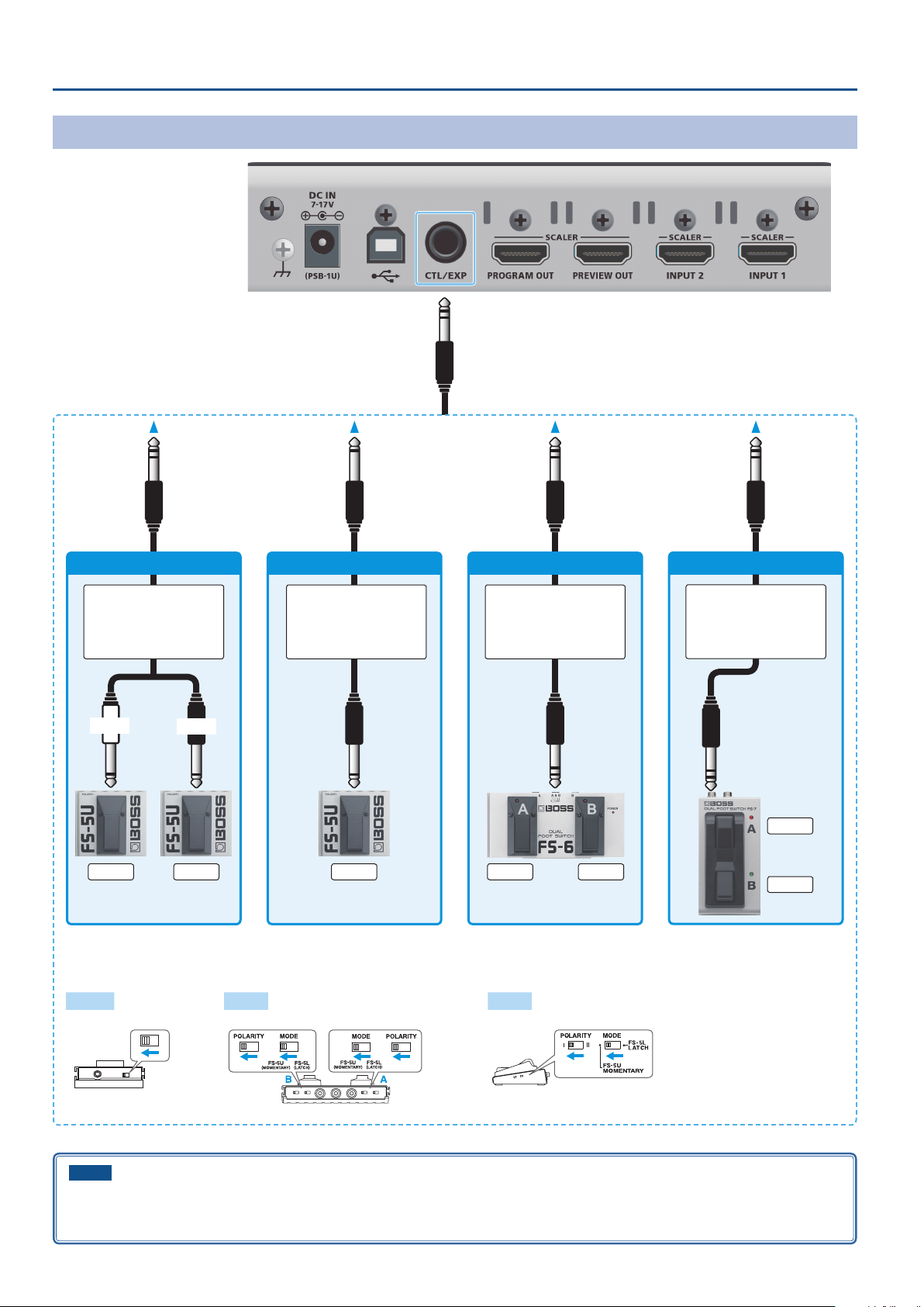
Connecting a Footswitch
FS-5U x 2
Stereo 1/4” phone type
.
/
1/4” phone type x 2
TIP
RING
CTL BCTL A
FS-5U x 1
1/4” phone type
.
/
1/4” phone type
CTL B
Stereo 1/4” phone type
Stereo 1/4” phone type
MODE/POLARITY switch
FS-5U FS-6 FS-7
FS-6
.
/
FS-7
Stereo 1/4” phone type
.
/
Stereo 1/4” phone type
CTL A
CTL BCTL A
CTL B
NOTE
The BOSS FS-6’s A, B, and A&B jacks also act as the power switch. The power turns on when you insert a plug into the jack, and turns o when
you remove the plug.
To prevent the batteries from running down, remove the plugs from the jacks when you’re not using the BOSS FS-6.
6
Page 7
Basic Operations
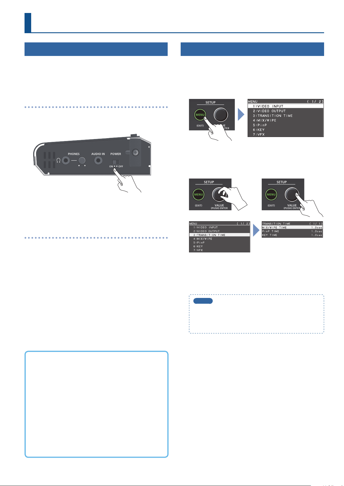
Turning the Power On/O
* Before turning the unit on/o, always be sure to turn the volume
down. Even with the volume turned down, you might hear some
sound when switching the unit on/o. However, this is normal
and does not indicate a malfunction.
Turning the power on
1. Make sure that all devices are powered-o.
2. Turn on the V-02HD’s [POWER] switch.
3. Turn on the power in the order of source devices
output devices.
0
Operating the Menu
Here’s how to access the menu, and make video/audio settings and
settings for the V-02HD itself. The menu is shown on the display that’s
connected to the PREVIEW OUT connector.
1. Press the [MENU] button to display the MENU screen.
The menu is organized into functions.
2. Turn the [VALUE] knob to move the cursor to the menu
item that you want to change, and then press the
[VALUE] knob.
Turning the power o
1. Turn o the power in the order of output devices
source devices.
2. Turn o the V-02HD’s [POWER] switch.
About the Auto O function
The power to the V-02HD turns o automatically when all of the
following states persist for 240 minutes (Auto O function).
5
No operation performed on the V-02HD
5
No audio or video input
5
No equipment is connected to the PROGRAM OUT/PREVIEW
OUT connectors
0
3. Repeat step 2 as needed.
Pressing the [MENU] button moves you back one level higher.
4. Turn the [VALUE] knob to change the setting value, and
then press the [VALUE] knob to conrm.
MEMO
5
By turning the [VALUE] knob while pressing it, you can
change the value more greatly.
5
Long-pressing the [VALUE] knob returns the current menu
item you’re setting to its default value.
5. Press the [MENU] button several times to close the menu.
If you do not want the power to be turned o automatically,
disengage the Auto O function. Press the [MENU]
button0“SYSTEM”0set “AUTO OFF” to “OFF.”
* Unsaved data is lost when the power turns o. Before turning
the power o, save the data that you want to keep.
* To restore power, turn the power on again.
7
Page 8
Video Input/Output Settings
List of Compatible Video Formats
Input video formats
Frame rate
When set to “59.94 Hz” When set to “50 Hz”
480/59.94i 576/50i
480/59.94p 576/50p
720/59.94p 720/50p
1080/59.94i 1080/50i
1080/59.94p 1080/50p
VGA (640 x 480/60 Hz) VGA (640 x 480/60 Hz)
SVGA (800 x 600/60 Hz) SVGA (800 x 600/60 Hz)
XGA (1024 x 768/60 Hz) XGA (1024 x 768/60 Hz)
WXGA (1280 x 800/60 Hz) WXGA (1280 x 800/60 Hz)
FWXGA (1366 x 768/60 Hz) FWXGA (1366 x 768/60 Hz)
SXGA (1280 x 1024/60 Hz) SXGA (1280 x 1024/60 Hz)
SXGA+ (1400 x 1050/60 Hz) SXGA+ (1400 x 1050/60 Hz)
UXGA (1600 x 1200/60 Hz) UXGA (1600 x 1200/60 Hz)
WUXGA (1920 x 1200/60 Hz) WUXGA (1920 x 1200/60 Hz)
Audio input format HDMI: Linear PCM, 24 bits/48 kHz, 2 ch
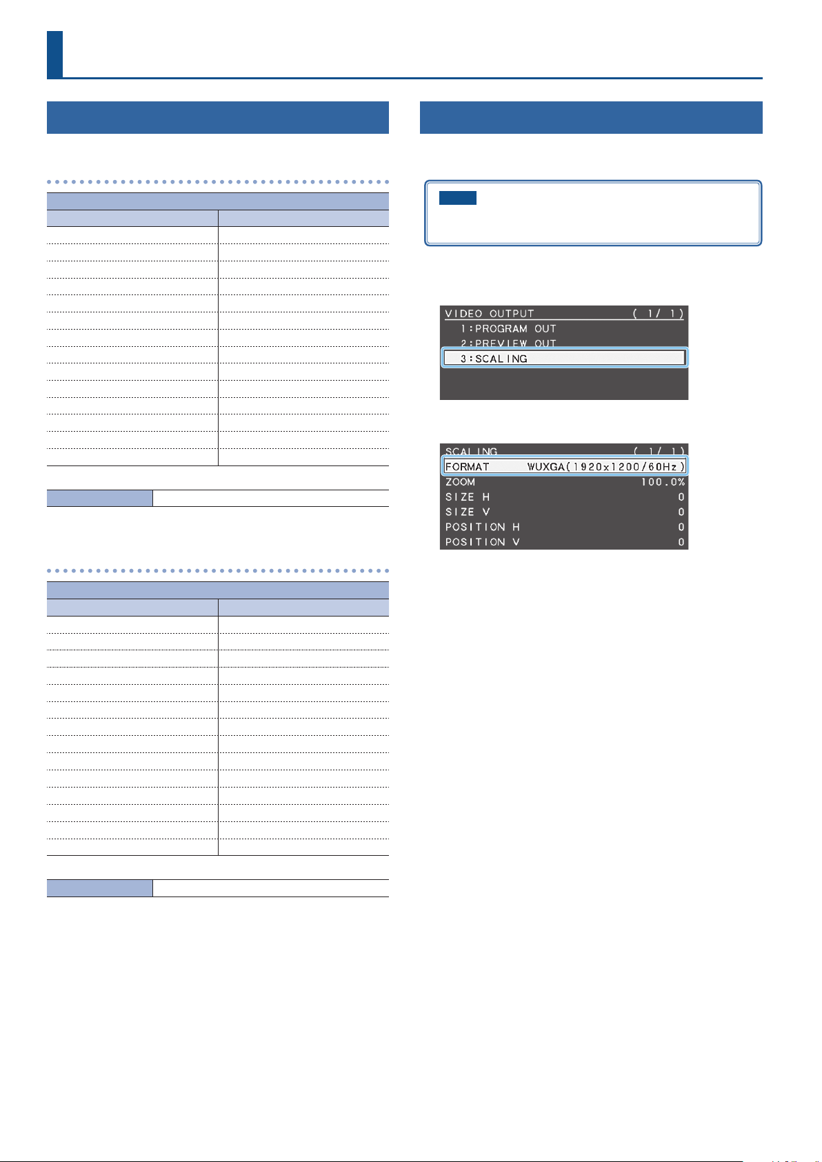
Setting the Output Format
Here’s how to specify the output format as appropriate for the device
that’s connected.
NOTE
If the display does not support the V-02HD’s output format, the
image might not be shown correctly.
1. [MENU] button
2. Use the [VALUE] knob to select “FORMAT.”
0
“VIDEO OUTPUT”0select “SCALING.”
Output video formats
Frame rate
When set to “59.94 Hz” When set to “50 Hz”
480/59.94p 576/50p
720/59.94p 720/50p
1080/59.94i 1080/50i
1080/59.94p 1080/50p
SVGA (800 x 600/60 Hz) SVGA (800 x 600/75 Hz)
XGA (1024 x 768/60 Hz) XGA (1024 x 768/75 Hz)
WXGA (1280 x 800/60 Hz) WXGA (1280 x 800/75 Hz)
FWXGA (1366 x 768/60 Hz) FWXGA (1366 x 768/75 Hz)
SXGA (1280 x 1024/60 Hz) SXGA (1280 x 1024/75 Hz)
SXGA+ (1400 x 1050/60 Hz) SXGA+ (1400 x 1050/75 Hz)
UXGA (1600 x 1200/60 Hz) UXGA (1600 x 1200/60 Hz)
WUXGA (1920 x 1200/60 Hz) WUXGA (1920 x 1200/60 Hz)
HD (1280 x 720/60Hz) HD (1280 x 720/60Hz)
FHD (1920 x 1080/60Hz) FHD (1920 x 1080/60Hz)
Audio input format HDMI: Linear PCM, 24 bits/48 kHz, 2 ch
3. Use the [VALUE] knob to set the output format.
4. Press the [VALUE] knob to conrm.
The output format switches.
5. Press the [MENU] button several times to close the menu.
8
Page 9
Video Input/Output Settings
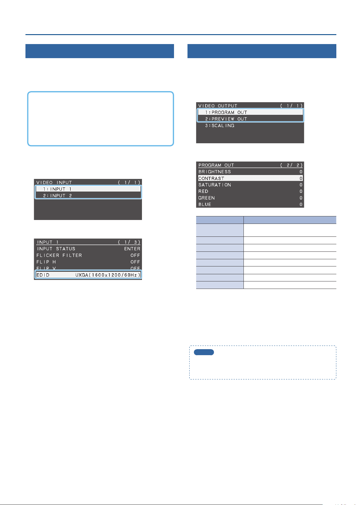
Specifying the Input Format (EDID)
With the factory settings, EDID is set to “INTERNAL” (the unit transmits
EDID information for all formats that it is able to input).
Change this setting if you want EDID information for a specic input
format to be sent to a source device.
What is EDID?
EDID is data that is transmitted from the V-02HD to the source
device when the V-02HD is connected to a source device. EDID
contains data such as the formats that can be input to the V-02HD
(resolution, color space, color depth) and audio information.
Based on the EDID information that the source device receives, it
will output the most appropriate video format to the V-02HD.
1. [MENU] button
“INPUT 2.”
2. Use the [VALUE] knob to select “EDID.”
3. Use the [VALUE] knob to set the input format (EDID).
4. Press the [VALUE] knob to conrm.
The input format (EDID) switches.
5. Press the [MENU] button several times to close the menu.
0
“VIDEO INPUT”0select “INPUT 1” or
Adjusting Output Video
Here’s how to adjust the output image appropriately for the device
that’s receiving the V-02HD’s output.
1. [MENU] button
OUT” or “PREVIEW OUT.”
2. Use the [VALUE] knob to select a menu item.
Menu item Explanation
COLOR SPACE
DVI-D/HDMI SIGNAL Species the output mode for HDMI output.
BRIGHTNESS Adjusts the brightness.
CONTRAST Adjusts the contrast.
SATURATION Adjusts the saturation.
RED Adjusts the red level.
GREEN Adjusts the green level.
BLUE Adjusts the blue level.
3. Use the [VALUE] knob to change the value, and press the
[VALUE] knob to conrm.
4. Repeat steps 2–3 as necessary.
5. Press the [MENU] button several times to close the menu.
0
“VIDEO OUTPUT”0select “PROGRAM
Species the color space (system for
representing colors in video).
MEMO
You can output a test pattern, useful for adjusting the image
quality of a display. Use the SYSTEM menu item “TEST PATTERN”
to specify the test pattern that is output.
9
Page 10
Video Input/Output Settings
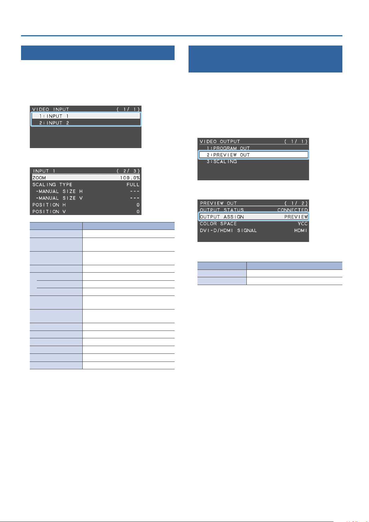
Adjusting the Input Video
Here’s how to adjust the character and scaling of the video that’s
input to INPUT 1 and 2.
1. [MENU] button
“INPUT 2.”
2. Use the [VALUE] knob to select a menu item.
Menu item Explanation
FLICKER FILTER If this is “ON,” ickering is reduced.
FLIP H
FLIP V
ZOOM Adjusts the zoom ratio.
SCALING TYPE Species the scaling type.
MANUAL SIZE H (*1) Adjusts the horizontal size.
MANUAL SIZE V (*1) Adjusts the vertical size.
POSITION H
POSITION V
BRIGHTNESS Adjusts the brightness.
CONTRAST Adjusts the contrast.
SATURATION Adjusts the saturation.
RED Adjusts the red level.
GREEN Adjusts the green level.
BLUE Adjusts the blue level.
(*1) This is valid when “SCALING TYPE” is set to “MANUAL.”
0
“VIDEO INPUT”0select “INPUT 1” or
If this is “ON,” the video is input with left
and right ipped.
If this is “ON,” the video is input with top
and bottom ipped.
Adjusts the display position in the
horizontal direction.
Adjusts the display position in the vertical
direction.
Outputting the Program Video from the PREVIEW OUT Connector
Here’s how you can output the program video to the display that’s
connected to the PREVIEW OUT connector.
This can be useful in situations such as live distribution, since the
same video as seen by the viewers can be shown on a dierent
display that is used by the performers to monitor themselves.
1. [MENU] button
OUT.”
2. Use the [VALUE] knob to select “OUTPUT ASSIGN.”
3. Use the [VALUE] knob to set it to “PROGRAM.”
Menu item Explanation
PROGRAM Output the program video.
PREVIEW Output the preview video (standby video).
4. Press the [VALUE] knob to conrm.
5. Press the [MENU] button several times to close the menu.
0
“VIDEO OUTPUT”0select “PREVIEW
3. Use the [VALUE] knob to change the value, and press the
[VALUE] knob to conrm.
4. Repeat steps 2–3 as necessary.
5. Press the [MENU] button several times to close the menu.
10
Page 11
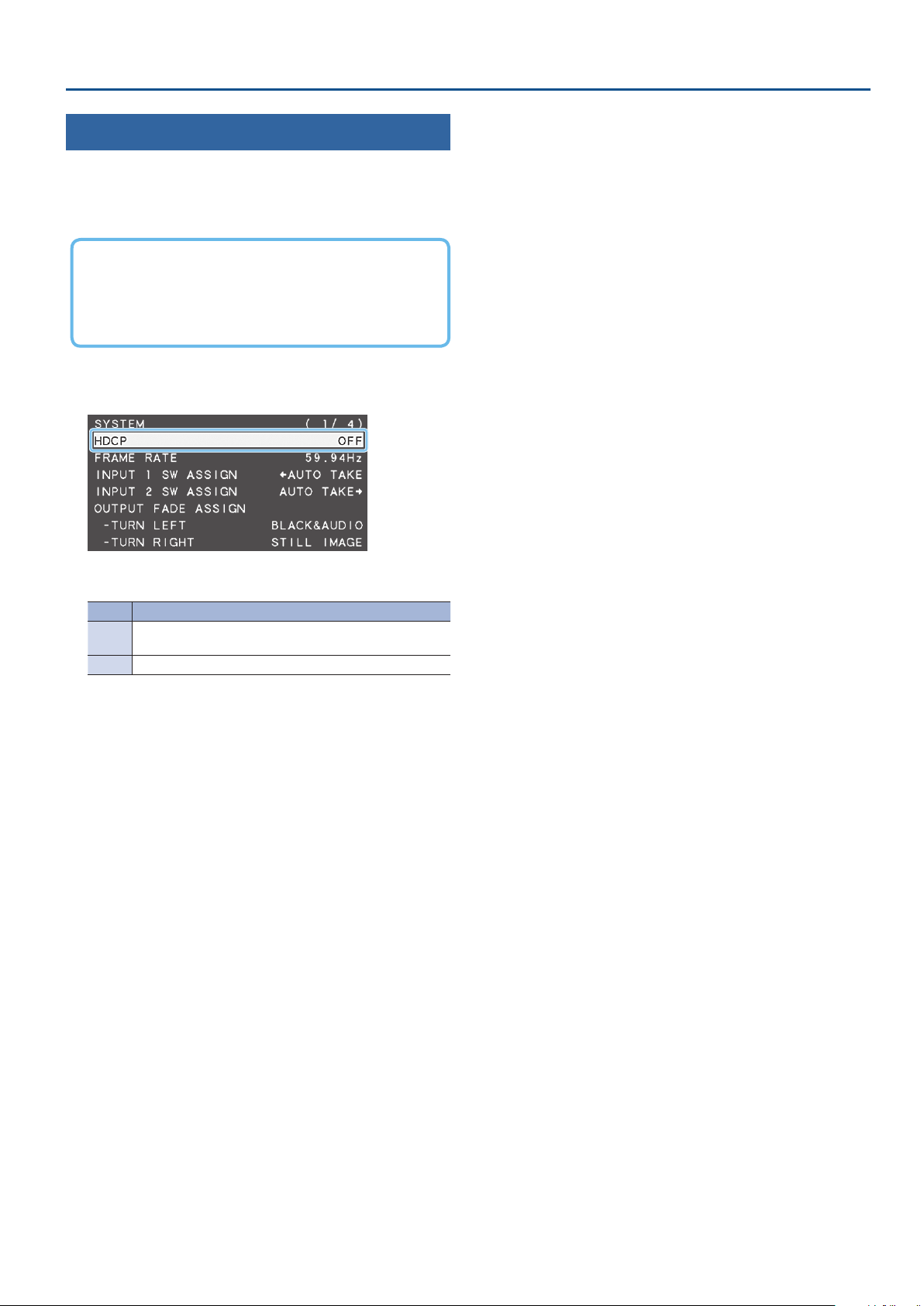
Inputting Copy-Protected (HDCP) Video
If you want to input HDCP-protected video from a BD player or other
device, you can enable HDCP input.
* If you want to output HDCP-protected video, connect an HDCP-
capable display.
What’s HDCP?
HDCP is copyright-protection technology that prevents unlawful
copying of content by encoding the path when sending digital
signals from a video playback device to a display monitor or
other display equipment.
Video Input/Output Settings
1. [MENU] button
0
“SYSTEM”0select “HDCP.”
2. Use the [VALUE] knob to set it to “ON.”
Value Explanation
HDCP-protected video can be input. HDCP is applied to the
ON
output video.
OFF HDCP-protected video cannot be input.
3. Press the [VALUE] knob to conrm.
4. Press the [MENU] button several times to close the menu.
11
Page 12
Video Operations
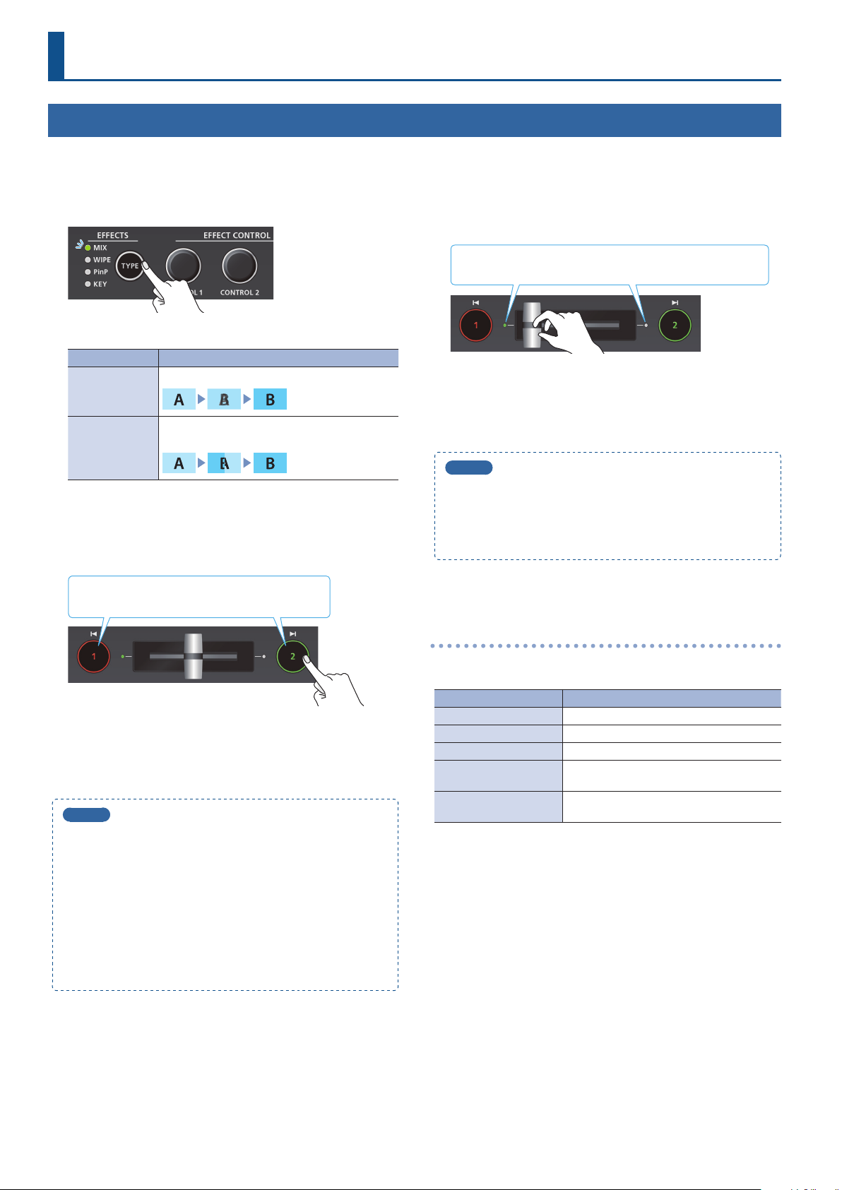
Using Mix/Wipe to Switch Video (MIX/WIPE)
Here’s how to switch between input video while applying an eect, and output the program.
1. Press the [TYPE] button several times to select the
transition eect (MIX, WIPE).
The MIX or WIPE indicator is lit.
Transition eects Explanation
The two videos are mixed as the transition occurs.
MIX
The next video moves across to replace the original
WIPE
video.
<Using the buttons to switch>
2. Press the button [1] or [2] that is lit green.
Lit red: Program output video
Lit green: Preview output video (standby video)
<Using the fader to switch>
2. Slide the video fader to the far left or far right.
The transition indicator for the video that is the program output
is lit. Slide the fader toward the side that is not lit.
The video is switched according to the movement of the video
fader.
When the video has switched completely, the lit state (red, green)
of buttons [1] [2] is exchanged.
MEMO
Depending on the timing at which you switch the video eect,
the position of the video fader might dier from the actual
output. If you operate the video fader in this state, the output
does not change until the position of the video fader matches
the actual output.
The button you press blinks red, and the video switches.
When the video has switched completely, the lit state (red, green)
of buttons [1] [2] is exchanged.
MEMO
5
Video transition time
If you use the buttons to switch video, the transition occurs
over a pre-specied time. To specify the video transition time,
set the TRANSITION menu item “MIX/WIPE TIME.”
5
Functions of the [1] [2] buttons
You can assign other functions to the [1] [2] buttons, such as
Cut (instant transition). To specify this, set the SYSTEM menu
items “INPUT 1 SW ASSIGN” and “INPUT 2 SW ASSIGN.”
* These settings are eectively only if mix/wipe are selected
as the video eect.
Changing the mix/wipe pattern
You can use the MIX/WIPE menu to specify the pattern by which the
mix/wipe occurs and the direction of the wipe.
Menu item Explanation
MIX TYPE Species the transition pattern for mix.
WIPE TYPE Species the transition pattern for wipe.
WIPE DIRECTION Species the direction of wipe.
WIPE BORDER COLOR
WIPE BORDER WIDTH
You can also use the [CONTROL 1] [CONTROL 2] knobs to change the
settings of the MIX/WIPE menu.
When mix is selected
[CONTROL 1] knob: Pattern of the mix transition
When wipe is selected
[CONTROL 1] knob
Turn: Pattern of the wipe transition
Turn while pressing: Color of the border added to the periphery of
[CONTROL 2] knob
Turn: Direction of wipe
Turn while pressing: Width of the border added to the periphery of
Species the color of the border added to
the edge of the wipe area.
Species the width of the border added to
the edge of the wipe area.
the wipe
the wipe
12
Page 13
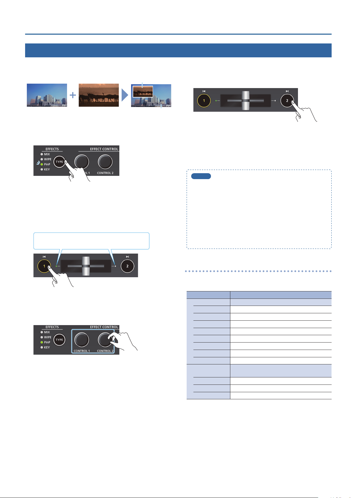
Using Picture-In-Picture to Composite Video (PinP)
Here’s how to composite an inset screen (a small separate screen) onto the background video.
Video Operations
Inset screen
Background video
1. Press the [TYPE] button several times to select PinP.
The PinP indicator is lit green, and the inset screen is shown in the
preview output video (standby video).
You can check the position and size of the inset screen that will be
composited before outputting the program.
2. Press the [1] button (lit yellow) to select the background
video and the inset screen.
The transition indicator (left or right) of the selected
background video is lit.
4. Press the [2] button.
The inset screen is composited with the background video, and
output as the program. The [2] button is lit red.
When you press the [2] button once again, the [2] button goes
dark and the inset screen disappears.
MEMO
5
The fade time over which the inset screen appears or
disappears when you press the [2] button is specied by the
setting of the TRANSITION menu item “PinP TIME.”
5
You can also use the video fader to show or hide the inset
screen.
5
If a video composited by PinP is being output as the program,
the PinP indicator is lit red.
5
You can make the composited result be immediately sent
from program output when selecting PinP in step 1. Set the
PinP menu item “PinP PROGRAM OUT MODE” to “AUTO.”
Each time you press the [1] button, the background video and the
inset screen video that are output as the preview will alternate.
3. Use the [CONTROL 1] [CONTROL 2] knobs to adjust the
inset screen.
[CONTROL 1] knob
Turn: Horizontal display position of the inset screen
Turn while pressing: Size of the inset screen (zoom)
[CONTROL 2] knob
Turn: Vertical display position of the inset screen
Turn while pressing: Zoom ratio of the inset screen
Making detailed settings for the inset screen
You can use the PinP menu to specify the shape and size of the inset
screen, and the color of the border that is added to the inset screen.
Menu item Explanation
WINDOW Use the following items to adjust the inset screen.
POSITION H Adjusts horizontal display position.
POSITION V Adjusts vertical display position
SIZE Adjusts the size (zoom).
CROPPING H Adjusts the horizontal size.
CROPPING V Adjusts the vertical size.
SHAPE Species the shape (rectangle, circle, diamond).
BORDER COLOR Species the color of the border.
BORDER WIDTH Adjusts the width of the border.
VIEW
POSITION H Adjusts the horizontal position.
POSITION V Adjusts the vertical position.
ZOOM Adjusts the zoom.
Use the following items to adjust the video that is
shown in the inset screen.
13
Page 14
Video Operations
Using a Key to Composite Video (KEY)
Here’s how you can turn a portion of the video transparent and composite it with the background video. You can use luminance key with either a
black or a white background, or a chroma key with either a blue or green background.
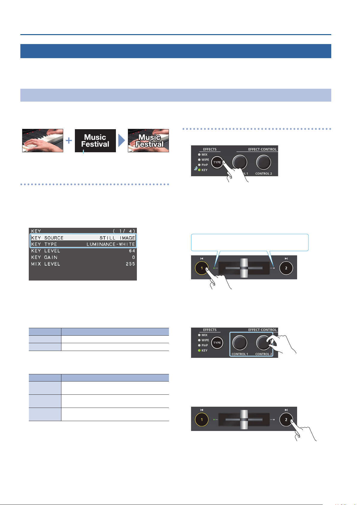
Compositing a Logo or Image (Luminance Key)
You can cut out a logo or image by turning its black or white portion transparent, and then superimpose it on the background video.
Background video
Logo or image to
be overlaid
Black or white
Specifying the source and key type for the logo or image
Specify the source of the logo or image that you want to
superimpose, and specify the key type used for compositing.
1. [MENU] butto
T YP E.”
2. Use the [VALUE] knob to change the value, and press the
[VALUE] knob to conrm.
7KEY SOURCE
Select the source of the logo or image that you want to
superimpose.
Value Explanation
INPUT 1, 2 The video of INPUT 1 or 2
STILL IMAGE A captured still image (p. 20)
0
“KEY”0select “KEY SOURCE” or “KEY
Compositing using luminance key
1. Press the [TYPE] button several times to select KEY.
The KEY indicator is lit green, and the composition results is
shown in the preview output video (standby video).
You can check the key-composited logo or image before you
output to program.
2. Press the [1] button to select the video of either INPUT 1
or 2 as the background.
The transition indicator (left or right) of the selected
background video is lit.
Each time you press the [1] button, the background video being
output as the preview will switch.
3. Use the [CONTROL 1] [CONTROL 2] knobs to adjust the
depth of the eect that is applied.
7KEY TYPE
Choose “LUMINANCE-WHITE” or “LUMINANCE-BLACK.”
Value Explanation
LUMINANCEWHITE
LUMINANCEBLACK
CHROMA
Composite using luminance key. Makes white
portions transparent according to brightness.
Composite using luminance key. Makes black
portions transparent according to brightness.
Composite using chroma key. Makes the specied
key color transparent according to hue.
3. Press the [MENU] button several times to close the menu.
14
[CONTROL 1] knob
Adjusts the degree of extraction for the key.
[CONTROL 2] knob
Adjusts the degree of edge blur for the key.
4. Press the [2] button.
The composited result is output as the program. While it is output
as the program, the [2] button and the KEY indicator are lit red.
When you press the [2] button once again, the [2] button goes
dark and the logo or image disappears.
Page 15

MEMO
5
The fade time over which the logo/image appears or
disappears when you press the [2] button is specied by the
setting of the TRANSITION menu item “KEY TIME.”
5
You can also use the video fader to show or hide the logo/
image.
5
You can make the composited result be immediately sent
from program output when selecting KEY in step 1. Set the
KEY menu item “KEY PROGRAM OUT MODE” to “AUTO.”
Modifying the logo or image
When using key compositing, you can ll-in the superimposed logo
or image, or add an edge to it. Make these settings in the following
KEY menu.
* These settings are shared with chroma key.
Menu item Explanation
FILL TYPE
MATTE COLOR
EDGE TYPE Species the type of edge.
EDGE COLOR Species the color of the edge.
EDGE WIDTH Species the width of the edge.
If this is set to “MATTE,” the superimposed logo or
image is lled-in with the specied color.
The ll-in color is specied by “MATTE COLOR.”
Video Operations
15
Page 16
Video Operations
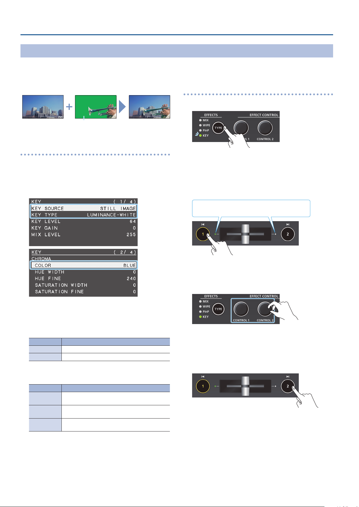
Compositing a Subject and Background (Chroma Key)
You can cut out a video by turning its blue or green portion transparent, and then superimpose it on the background video. This lets you
composite a subject that’s photographed against a blue background or green background.
Video to be
Background video
superimposed
Blue or green
Specifying the source and key type for the video
Specify the source and key type for the video that you want to
superimpose.
1. [MENU] button
TYPE,” or “COLOR.”
0
“KEY”0select “KEY SOURCE,” “KEY
Compositing using chroma key
1. Press the [TYPE] button several times to select KEY.
The KEY indicator is lit green, and the composition results is
shown in the preview output video (standby video).
You can check the key-composited video before you output to
program.
2. Press the [1] button to select the video of either INPUT 1
or 2 as the background.
The transition indicator (left or right) of the selected
background video is lit.
2. Use the [VALUE] knob to change the value, and press the
[VALUE] knob to conrm.
7KEY SOURCE
Select the source of the video that you want to superimpose.
Value Explanation
INPUT 1, 2 The video of INPUT 1 or 2
STILL IMAGE A captured still image (p. 20)
7KEY TYPE
Set to “CHROMA.”
Value Explanation
LUMINANCEWHITE
LUMINANCEBLACK
CHROMA
7COLOR
Specify either “GREEN” or “BLUE” as the key color for chroma key
(the color to be removed).
Composite using luminance key. Makes white
portions transparent according to brightness.
Composite using luminance key. Makes black
portions transparent according to brightness.
Composite using chroma key. Makes the specied
key color transparent according to hue.
Each time you press the [1] button, the background video being
output as the preview will switch.
3. Use the [CONTROL 1] [CONTROL 2] knobs to adjust the
depth of the eect that is applied.
[CONTROL 1] knob
Adjusts the degree of extraction for the key.
[CONTROL 2] knob
Adjusts the degree of edge blur for the key.
4. Press the [2] button.
The composited result is output as the program. While it is output
as the program, the [2] button and the KEY indicator are lit red.
When you press the [2] button once again, the [2] button goes
dark and the superimposed video disappears.
3. Press the [MENU] button several times to close the menu.
16
Page 17
Video Operations
MEMO
5
The fade time with which the video superimposed by the [2]
button appears or disappears is specied by the TRANSITION
menu item “KEY TIME.”
5
You can also reveal or hide the superimposed video by
operating the video fader.
5
You can make the composited result be immediately sent
from program output when selecting KEY in step 1. Set the
KEY menu item “KEY PROGRAM OUT MODE” to “AUTO.”
Finely adjusting the key color (removed color)
You can use the following KEY menu to make ne adjustments to the
key color (the color that is removed).
Menu item Explanation
CHROMA
HUE WIDTH Adjusts the hue width.
HUE FINE Adjusts the center position of the hue.
SATURATION WIDTH Adjusts the saturation width.
SATURATION FINE This adjusts the center position of saturation.
Use the following items to make ne
adjustments to the key color.
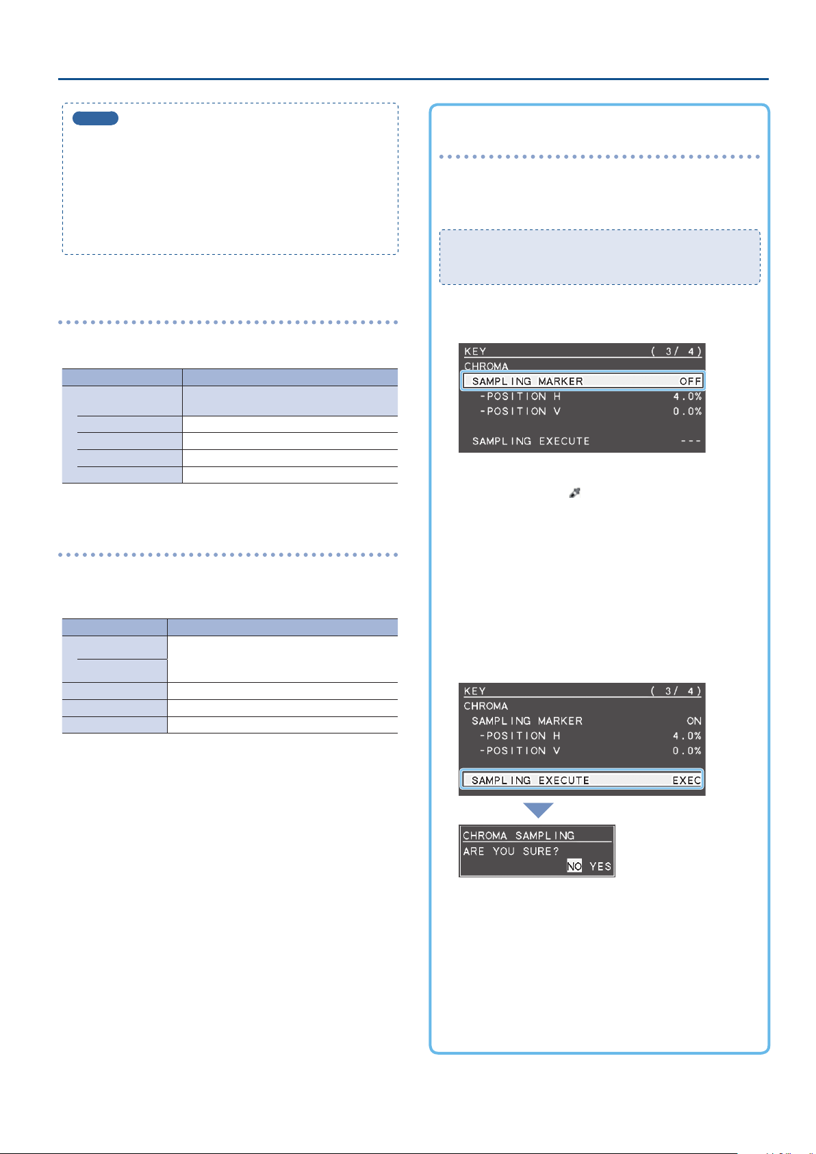
To specify a desired color as the key color
(sampling marker)
You can specify the key color to be made transparent simply by
sampling (detecting) a color from the video. (This is called the
sampling marker function.) You can also specify a key color other
than green or blue.
To use the sampling marker function, set the KEY menu item
“KEY TYPE” to “CHROMA,” and use the [TYPE] button to select
“KEY.”
1. [MENU] button
MARKER.”
2. Use the [VALUE] knob to set it to “ON.”
The sampling marker ( ) for sampling (detecting) the key
color appears in the preview output video.
0
“KEY”0select “SAMPLING
Modifying the superimposed video
When using key compositing, you can ll-in the superimposed video,
or add an edge to it. Make these settings in the following KEY menu.
* These settings are shared with luminance key.
Menu item Explanation
FILL TYPE
MATTE COLOR
EDGE TYPE Species the type of edge.
EDGE COLOR Species the color of the edge.
EDGE WIDTH Species the width of the edge.
If this is set to “MATTE,” the superimposed video is
lled-in with the specied color.
The ll-in color is specied by “MATTE COLOR.”
3. Press the [VALUE] knob to conrm.
4. Use the [CONTROL 1] [CONTROL 2] knobs to adjust
the position of the sampling marker.
[CONTROL 1] knob
Adjusts the horizontal position.
[CONTROL 2] knob
Adjusts the vertical position.
5. Use the [VALUE] knob to select “SAMPLING EXECUTE.”
A recognition message appears.
If you want to cancel the operation, press the [MENU] button.
6. Use the [VALUE] knob to select “YES,” and press the
[VALUE] knob.
The key color is sampled.
The “HUE WIDTH,” “HUE FINE,” “SATURATION WIDTH,” and
“SATURATION FINE” settings are adjusted automatically.
7. Press the [MENU] button several times to close the
menu.
17
Page 18
Video Operations
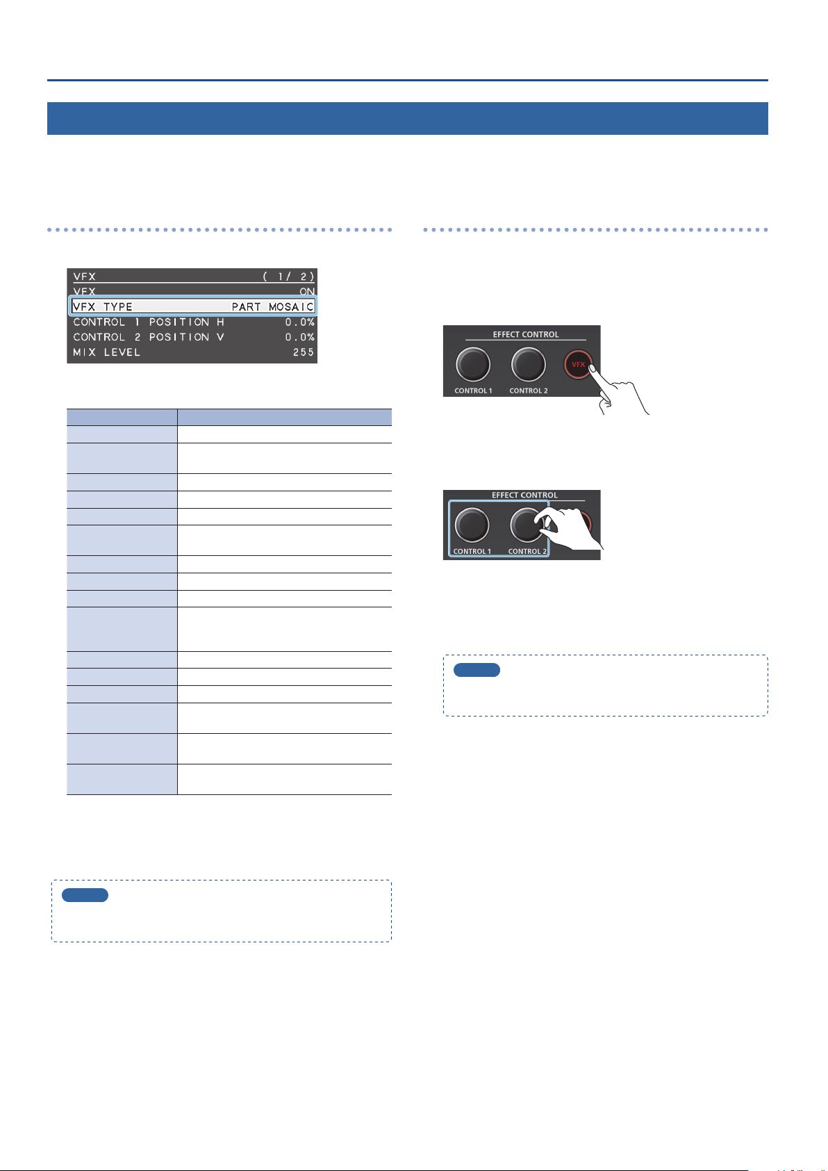
Applying a Visual Eect to the Video (VFX)
Here’s how you can apply an eect to the entire video, such as varying the video’s color or shape. You can apply a visual eect even while using
picture-in-picture (p. 13) or key (p. 14, 16) to composite the video.
Selecting a visual eect
1. [MENU] button
2. Use the [VALUE] knob to select the visual eect.
Value Explanation
PART MOSAIC Applies a mosaic to the selected region.
BACKGROUND
MOSAIC
FULL MOSAIC Applies a mosaic to the entire screen.
WAVE Makes the video wavy.
RGB REPLACE Exchanges the colors.
COLORPASS
NEGATIVE Inverts the brightness and colors.
COLORIZE Adds color to the video.
POSTERIZE Changes the gradations in brightness.
SILHOUETTE
EMBOSS Adds a bas-relief eect to the video.
FIND EDGES Extracts contours.
MONOCOLOR Turns the video monochrome.
HUE OFFSET
SATURATION OFFSET
VALUE OFFSET
0
“VFX”0select “VFX TYPE.”
Applies a mosaic to the portion outside the
selected region.
Turns the video black and white while
preserving a specic color.
Separates the video into light and dark areas,
and makes the dark areas black and adds a
dierent color to the light areas.
Changes the visual character by controlling
the hue.
Changes the visual character by controlling
the saturation.
Changes the visual character by controlling
the brightness.
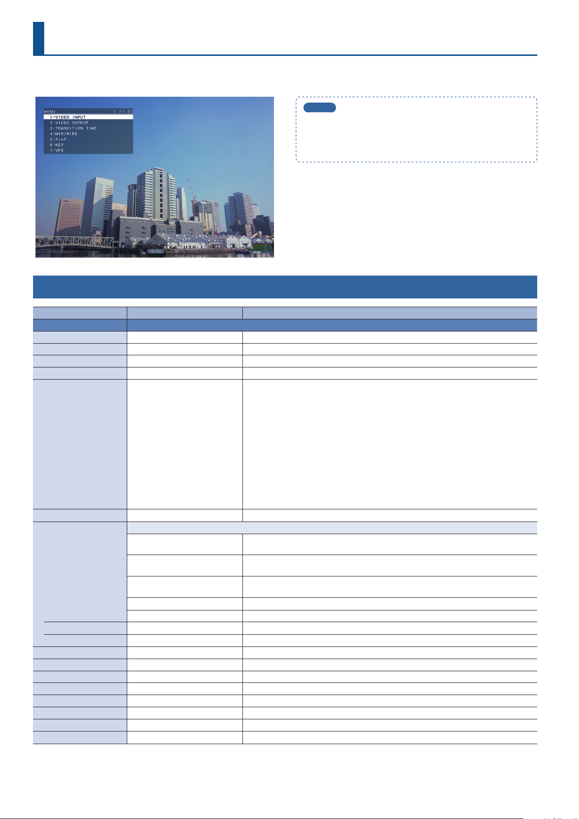
Applying visual eects
1. Send the video on which you want to apply an eect to
the program output.
2. Press the [VFX] button to turn on the visual eect
(making the button light up).
The visual eect is applied to the program output video.
3. Use the [CONTROL 1] or [CONTROL 2] knob to adjust the
degree of eect applied.
For “PART MOSAIC” and “BACKGROUND MOSAIC,” you can adjust
the following settings by turning the [CONTROL 1] or [CONTROL 2]
knobs while pressing them.
[CONTROL 1] knob: Size of the selected region
[CONTROL 2] knob: Mosaic detail (block size)
MEMO
Settings for the eect that is controlled by the [CONTROL 1]
[CONTROL 2] knobs can be checked in the VFX menu.
4. To turn o a visual eect, press the [VFX] button once
again.
3. Press the [VALUE] knob to conrm.
4. Press the [MENU] button several times to close the menu.
MEMO
You can change the type of the visual eect by holding down
the [VFX] button and turning the [CONTROL 1] knob.
18
Page 19

Applying a Fade to the Program Output Video (Output Fade)
Here’s how to perform a fade-out from the program output video to a
black screen, or a fade-in from a black screen to the program output
video.
You can insert a black screen into the program output video at times
where you don’t want to output a picture, such as at intervals in
presentations or band performances.
* The fade-in/out eect is applied only to the program output.
Applying a Fade-out
1. Turn the [OUTPUT FADE] knob fully counterclockwise.
The program output video fades to a black screen.
When fade is applied, the [OUTPUT FADE] knob indicator blinks
red. When the fade-out is complete, the indicator is lit red.
Video Operations
Applying a Fade-in
1. Return the [OUTPUT FADE] knob to the center.
The [OUTPUT FADE] knob indicator goes dark, and program
output begins.
MEMO
By changing the function that’s assigned to the [OUTPUT FADE]
knob, you can fade-in/out using a white screen. Make these
settings in the SYSTEM menu items OUTPUT FADE ASSIGN
“TURN LEFT” and “TURN RIGHT.”
19
Page 20

Video Operations
Using a Captured Still Image
A still image captured from the input video can be output in the same way as the video. You can also use it as a source for key compositing (p. 14, 16).
Specifying how the still image is saved
The captured still image can be saved in either of two ways: saved
in the unit or temporarily saved in the unit (and deleted when the
power turns o). The captured resolution diers depending on the
method of saving.
The method of saving the still image is specied by the CAPTURE
IMAGE menu settings “SAVE TO INTERNAL STORAGE.” Choose the save
method as appropriate for the still image that you want to use.
Value Explanation
The still image is captured at the actual resolution and
temporarily saved in the unit. When you turn o the power,
DISABLE
ENABLE
the captured still image is deleted.
This allows the image to be captured without impairing the
image quality. It is suitable for still images that include a logo
or small characters.
The still image is captured at a reduced resolution of 640 x
360 and saved in the unit. Since the still image is expanded
when it is output, the image quality might be impaired.
MEMO
5
The unit can only save one still image (including temporary
saving). If a still image is already saved, it is overwritten when
you execute a new capture.
5
If the still image output function is assigned to the [OUTPUT
FADE] knob, the [OUTPUT FADE] knob indicator shows
whether a still image exists.
Unit contains still image
Lit green/red
Dark Unit contains no still image
When lit red, the still image is
being output
Capturing a still image
Here’s how to capture a still image from the input video.
NOTE
5
If the CAPTURE IMAGE menu item “SAVE TO INTERNAL
STORAGE” is set to “ENABLE” (save still image to unit), it will
take approximately 30 seconds for capture to be completed.
5
Input stops for the video being captured.
< To capture by operating a button >
1. Press the [TYPE] button several times to select the
transition eect (MIX, WIPE).
* You can capture by operating a button only if mix or wipe is
selected as the video eect.
2. According to the still image that you want to capture,
long-press the [1] or [2] button (three seconds or longer).
Long-press (three seconds or longer)
The function of the [OUTPUT FADE] knob is specied by the
SYSTEM menu settings OUTPUT FADE ASSIGN “TURN LEFT”
and “TURN RIGHT.”
5
Regarding copy-protected (HDCP) video
If you capture a still image from copy-protected (HDCP) video,
the resulting still image is treated in the same way as HDCP
video. The still image is shown or not shown depending on
whether HDCP is on or o (p. 11).
20
The capture is executed. Input stops for the video that is being
captured. When the normal output returns, capture is complete.
MEMO
If you’ve made settings in the SYSTEM menu to assign the
operation of the [1][2] buttons as follows, you can’t capture by
operating a button.
5
INPUT 1 SW ASSIGN:’TRANSFORM
5
INPUT 2 SW ASSIGN: TRANSFORM
&
Page 21

Video Operations
< To capture by operating the menu >
1. [MENU] butto
SOURCE.”
0
“CAPTURE IMAGE”0select “CAPTURE
2. Use the [VALUE] knob to select either “INPUT 1” or
“INPUT 2” according to the still image that you want to
capture.
3. Press the [VALUE] knob to conrm.
4. Use the [VALUE] knob to select “CAPTURE EXECUTE.”
Outputting a Still Image
1. Turn the [OUTPUT FADE] knob fully clockwise.
The [OUTPUT FADE] knob indicator is lit red, and the still image is
output from preview/program.
* When outputting the still image, the transition occurs by a cut
regardless of the transition eect that is selected.
2. To return to normal video output, return the [OUTPUT
FADE] knob to the center.
MEMO
You can also assign other functions to the [OUTPUT FADE]
knob. Make settings for the SYSTEM menu items OUTPUT FADE
ASSIGN “TURN LEFT” or “TURN RIGHT.”
Deleting a Still Image
A recognition message appears.
If you want to cancel the operation, press the [MENU] button.
5. Use the [VALUE] knob to select “YES,” and press the
[VALUE] knob.
The capture is executed. Input stops for the video that is being
captured.
When capture is complete, the message “COMPLETE” appears, and
normal output returns.
6. Press the [MENU] button to close the message.
7. Press the [MENU] button several times to close the menu.
Here’s how to delete the still image that’s saved in the unit.
1. [MENU] button
STILL IMAGE.”
A recognition message appears.
If you want to cancel the operation, press the [MENU] button.
0
“CAPTURE IMAGE”0select “DELETE
2. Use the [VALUE] knob to select “YES,” and press the
[VALUE] knob.
The still image is deleted. When the operation is nished, the
message “COMPLETE” appears.
3. Press the [MENU] button to close the message.
4. Press the [MENU] button several times to close the menu.
21
Page 22

Audio Operations
Adjusting the Volume Level
Here’s how to adjust the volume of the audio input and audio output.
1. [MENU] button
0
“AUDIO INPUT”0select “INPUT 1,”
“INPUT 2,” or “AUDIO IN.”
2. Use the [VALUE] knob to select “INPUT LEVEL.”
3. Use the [VALUE] knob to adjust the input volume.
Raise the volume level of audio you want to make more
prominent, for example, an emcee microphone, and lower the
volume level for other audio.
When no audio is input, and for audio that is unused, lower the
volume level to minimum (-INF).
4. Press the [VALUE] knob to conrm.
5. Press the [MENU] button twice to return to the MENU
screen.
6. Use the [VALUE] knob to select “AUDIO OUTPUT”
“OUTPUT LEVEL.”
0
Level meter indication
An audio level meter is shown at the lower
right of the preview display. The level meter
illumination lets you check whether the volume
is adjusted appropriately.
Indicator Status
Red
Yellow
Green
* If the volume level of speaker output is unsuitable even when
the volume level on the V-02HD has been adjusted so that level
meter light up in yellow, adjust the volume for the speakers
and ampliers. Using “OUTPUT LEVEL” to make adjustments can
sometimes result in distortion or poorer sound quality.
MEMO
5
If you use the [OUTPUT FADE] knob to fade-in/out the
program output video (p. 19), the output audio also fades-in/
out simultaneously.
5
You can change the function that’s assigned to the [OUTPUT
FADE] knob so that it adjusts only the output volume. Set the
SYSTEM menu item OUTPUT FADE ASSIGN “TURN LEFT” or
“TURN RIGHT” to “AUDIO.”
5
You can output a test tone that’s convenient when adjusting
the volume. In the SYSTEM menu item “TEST TONE,” specify
the test tone that will be output.
Lights up at 0 dB or higher.
It indicates an excessive volume level.
Lights up at -20 to -1 dB.
It indicates an appropriate volume level.
Lights up at -50 to -21 dB.
It indicates a too-low volume level.
7. Use the [VALUE] knob to adjust the output volume.
8. Press the [MENU] button several times to close the menu.
22
Page 23

Applying Eects to Input Audio
You can modify the tonal character by applying eects to the audio input.
Audio Operations
Using an eect preset
The V-02HD provides eect presets that are appropriate for specic
environments. Simply by selecting a preset you can easily apply the
appropriate eect for your purpose.
Each preset consists of a combination of three eects (high-pass
lter, compressor, equalizer).
MEMO
5
When you switch presets, the settings of each eect are
overwritten.
5
If you want to make ne adjustments to a preset, use the
AUDIO INPUT menu to edit the high-pass lter, compressor,
and equalizer settings.
Since the noise gate (an eect that eliminates noise) is not
included in the presets, you’ll need to make separate settings
for it.
For details on the eects, refer to “8: AUDIO INPUT” (p. 36).
1. [MENU] button
“INPUT 2,” or “AUDIO IN.”
2. Use the [VALUE] knob to select “EFFECT PRESET.”
0
”AUDIO INPUT”0select “INPUT 1,”
Correcting a time dierence between video and
audio (delay)
Here’s how you can correct a time dierence between the video and
audio by delaying the output of the input audio.
1. [MENU] button
“INPUT 2,” or “AUDIO IN.”
2. Use the [VALUE] knob to select “DELAY.”
3. Use the [VALUE] knob to adjust the time by which the
audio is delayed.
Delay the audio output so that the audio and video match.
4. Press the [MENU] button several times to close the menu.
0
“AUDIO INPUT”0select “INPUT 1,”
3. Use the [VALUE] knob to select an eect preset.
Value Explanation
DEFAULT For line input (default setting)
MEETING For meetings
INTERVIEW For interviews
AMBIENT MIC For capturing ambient sound
WINDY FIELD For capturing ambient sound in a windy area
4. Press the [VALUE] knob to conrm.
A recognition message appears.
If you want to cancel the operation, press the [MENU] button.
5. Use the [VALUE] knob to select “OK,” and press the
[VALUE] knob.
The preset is loaded. When the operation is nished, the message
“COMPLETE” appears.
6. Press the [MENU] button to close the message.
7. Press the [MENU] button several times to close the menu.
23
Page 24

Audio Operations
Applying Eects to Output Audio
You can modify the tonal character by applying eects to the audio
output.
1. [MENU] button
menu item.
* For details on the eects, refer to the following items.
2. Use the [VALUE] knob to change the value, and press the
[VALUE] knob to conrm.
3. Press the [MENU] button several times to close the menu.
LIMITER
Limits the output volume so that is does not exceed the set level.
Menu item Explanation
LIMITER Turns the limiter on/o.
THRESHOLD
0
“AUDIO OUTPUT”0select an eect
Adjusts the level that becomes the threshold at which
the limiter is applied. Compression is applied to audio
that exceeds the threshold. The volume level of audio
that is output is limited so as to stay to below the
threshold.
Silencing Only Specic Audio (Mute)
Here’s how to temporarily silence specic input audio or output
audio (the mute function).
Muting input audio
1. [MENU] button
0
”AUDIO INPUT”
“INPUT 2,” or “AUDIO IN.”
2. Use the [VALUE] knob to select “INPUT MUTE.”
3. Use the [VALUE] knob to set it to “ON.”
To cancel muting, specify “OFF.”
4. Press the [VALUE] knob to conrm.
5. Press the [MENU] button several times to close the menu.
0
select “
INPUT 1,”
EQUALIZER
Adjusts the sound quality for each frequency band.
Menu item Explanation
EQUALIZER Turns the equalizer on/o.
Hi GAIN Boosts or attenuates the high band.
Hi FREQUENCY
Mid GAIN Boosts or attenuates the middle band.
Mid FREQUENCY
Mid Q
Lo GAIN Boosts or attenuates the low band.
Lo FREQUENCY
Adjusts the center frequency when changing the
tone quality in the high band.
Adjusts the center frequency when changing the
tone quality in the middle band.
Adjusts the width of the frequency band when
boosting or attenuating the middle band.
Adjusts the center frequency when changing the
tone quality in the low band.
MULTI BAND COMPRESSOR
Applies separate compressors in individual frequency band.
Menu item Explanation
MULTI BAND
COMPRESSOR
Hi THRESHOLD
Mid THRESHOLD
Lo THRESHOLD
Hi RATIO
Mid RATIO
Lo RATIO
Turns the multi-band compressor on/o.
Specify the individual levels that become the
thresholds for the high, midrange, and low bands
at which the compressor is applied. Compression
is applied to audio that exceeds the threshold.
Specify the amount of compression applied in
the high, midrange, and low bands. The state in
which no compression is applied is dened as “1.”
Muting output audio
1. [MENU] button
MUTE.”
2. Use the [VALUE] knob to set it to “ON.”
To cancel muting, specify “OFF.”
3. Press the [VALUE] knob to conrm.
4. Press the [MENU] button several times to close the menu.
MEMO
The level meter shown at the lower right of the preview display
indicates the mute setting.
The “MT” symbol is shown to indicate audio for which muting is
on.
0
“AUDIO OUTPUT”0select “OUTPUT
24
Page 25

Audio Operations
Interlinking Audio Output to Video Switching (Audio Follow)
Here’s how the audio output can be automatically switched in tandem with video switching (the audio follow function). When you switch video,
only the audio of the currently selected input video is output, and the audio of the other input video is automatically muted.
1. As described in “Adjusting the Volume Level” (p. 22),
adjust the output volume as desired.
2. [MENU] button
or “INPUT 2.”
0
“AUDIO FOLLOW”0select “INPUT 1”
3. Use the [VALUE] knob to set it to “ON.”
Value Explanation
Enables the Audio Follow feature.
ON
OFF Disables the Audio Follow feature.
The audio of only the selected input video is output, and
the audio of the other input video is automatically muted.
4. Press the [VALUE] knob to conrm.
5. Press the [MENU] button several times to close the menu.
MEMO
The level meter shown at the lower right of the preview display
indicates the audio follow setting.
The “A.F” symbol is shown to indicate audio for which audio
follow is on.
Applying audio follow to the audio from AUDIO IN
1. [MENU] button
2. Use the [VALUE] knob to specify “INPUT 1” or “INPUT 2.”
Value Explanation
INPUT 1, 2
OFF
3. Press the [VALUE] knob to conrm.
4. Press the [MENU] button several times to close the menu.
0
“AUDIO FOLLOW” 0select “AUDIO IN.”
Species the input video (either INPUT 1 or 2) that uses
audio follow for the audio of AUDIO IN. The audio of
AUDIO IN is output only when the specied input video
is selected.
The audio of AUDIO IN is always output regardless of
the input video that’s selected.
25
Page 26

Other Features
Saving/Recalling Settings (Preset Memory)
You can save the current settings, including the video/audio settings and the state of the operating panel, in preset memory and recall those
settings for use when necessary. The V-02HD is provided with eight preset memories.
About the last memory function
The V-02HD has a built-in Last Memory feature. Last Memory is a feature that saves the state of the unit that is in eect immediately before
power-down, and automatically restores the state at the next startup. The Last Memory feature is enabled by default. If you want the unit to
recall a specic preset memory when it starts up, use the PRESET MEMORY menu item “START UP” to specify the preset memory number.
Saving to a preset memory
1. [MENU] button
0
“PRESET MEMORY”
2. Use the [VALUE] knob to specify the save-destination
preset memory number (1–8), and press the [VALUE] knob.
A recognition message appears.
If you want to cancel the operation, press the [MENU] button.
3. Use the [VALUE] knob to select “YES,” and press the
[VALUE] knob.
The current settings are saved. When the operation is nished, the
message “COMPLETE” appears.
4. Press the [MENU] button to close the message.
5. Press the [MENU] button several times to close the menu.
0
select “SAVE.”
Recalling a preset memory
1. [MENU] button
2. Use the [VALUE] knob to select the preset memory number
(1–8) that you want to recall, and press the [VALUE] knob.
A recognition message appears.
If you want to cancel the operation, press the [MENU] button.
3. Use the [VALUE] knob to select “YES,” and press the
[VALUE] knob.
The settings are recalled. When the operation is nished, the
message “COMPLETE” appears.
4. Press the [MENU] button to close the message.
5. Press the [MENU] button several times to close the menu.
0
”PRESET MEMORY”0select “LOAD.”
Initializing a preset memory
Here’s how you can initialize the settings of a specic preset memory
to the factory-set condition.
MEMO
5
By setting the PRESET MEMORY menu item “MEMORY
PROTECT” to “ON,” you can protect the preset memory from
being overwritten.
5
The state of the [PHONES] knob (headphone volume) is not
saved in preset memory.
5
The following settings are common to the unit (one set for the
entire unit), and therefore are not saved in preset memory.
5
PRESET MEMORY menu
5
CTL/EXP menu
5
CAPTURE IMAGE menu
5
SYSTEM menu
26
1. [MENU] button
“INITIALIZE.”
0
“PRESET MEMORY”0select
2. Use the [VALUE] knob to select the preset memory
number (1–8) that you want to initialize, and press the
[VALUE] knob.
A recognition message appears.
If you want to cancel the operation, press the [MENU] button.
3. Use the [VALUE] knob to select “YES,” and press the
[VALUE] knob.
The preset memory is initialized. When the operation is nished,
the message “COMPLETE” appears.
4. Press the [MENU] button to close the message.
5. Press the [MENU] button several times to close the menu.
Page 27

Other Features
Using a Footswitch
You can use a footswitch connected to the V-02HD to control the V-02HD with your foot. You can assign various functions to the footswitch.
1. [MENU] button
0
“CTL/EXP”0select “CTL/EXP TYPE.”
2. Use the [VALUE] knob to specify “CTL A & CTL B”
(footswitch) as the device that’s connected to the CTL/EXP
jack.
3. Press the [VALUE] knob to conrm.
4. Use the [VALUE] knob to select “CTL A ASSIGN” or “CTL B
ASSIGN.”
6. Press the [VALUE] knob to conrm.
7. Press the [MENU] button several times to close the menu.
MEMO
If a single-pedal type footswitch such as the BOSS FS-5U is
connected using a phone cable (mono), the function assigned
by “CTL B ASSIGN” is enabled.
NOTE
The BOSS FS-6’s jacks A, B, and A&B also act as the power
switch. The power turns on when you insert a plug into the
jack, and turns o when you remove the plug.
To prevent the batteries from running down, remove the plugs
from the jacks when you’re not using the BOSS FS-6.
5. Use the [VALUE] knob to select the function that you
want to assign to CTL A or CTL B of the footswitch.
Value Explanation
N/A No function is assigned.
EFFECT TYPE SW Presses the [TYPE] button.
EFFECT MIX Switches the video eect to mix (MIX).
EFFECT WIPE Switches the video eect to wipe (WIPE).
EFFECT PinP
EFFECT KEY Switches the video eect to key (KEY).
VFX SW Turns the [VFX] button on/o.
INPUT 1 SW Presses the [1] button.
INPUT 2 SW Presses the [2] button.
’
AUTO TAKE
’
CUT
STILL IMAGE
INPUT 1 AUDIO MUTE
INPUT 2 AUDIO MUTE
AUDIO IN AUDIO
MUTE
AUDIO OUTPUT MUTE
OUTPUT FADE LEFT
OUTPUT FADE RIGHT
LOAD MEMORY 1–8 Recalls MEMORY 1–8.
&
&
Switches the video eect to Picture in
Picture (PinP).
Switches the video between INPUT 1 and 2.
Switches the video between INPUT 1 and 2
as a cut.
Switches between still image output and
normal output.
Turns the mute function on/o for INPUT 1
audio.
Turns the mute function on/o for INPUT 2
audio.
Turns the mute function on/o for AUDIO
IN audio.
Turns on/o the mute function for output
audio.
Switches the [OUTPUT FADE] knob position
(center / turned fully counter-clockwise).
Switches the [OUTPUT FADE] knob position
(center / turned fully clockwise).
27
Page 28

Other Features
Using an Expression Pedal
You can use an expression pedal connected to the V-02HD to control the V-02HD with your foot.
Adjusting the pedal (pedal calibration)
The rst time you use an expression pedal, you must calibrate (adjust)
the pedal so that it will operate optimally.
In some cases, an expression pedal might no longer operate
optimally due to the passage of time or changes in the operating
conditions. If you notice problems such as slight movements of the
pedal causing a major change in volume, or if the video fails to switch
when you press the pedal, you should execute calibration.
1. [MENU] button
2. Use the [VALUE] knob to specify “EXP” (expression pedal)
as the device that’s connected to the CTL/EXP jack.
3. Press the [VALUE] knob to conrm.
4. Use the [VALUE] knob to select “EXP CALIBRATE.”
The EXP CALIBRATE screen appears.
0
“CTL/EXP”0select “CTL/EXP TYPE.”
Assigning a function to the pedal
You can assign various functions to the expression pedal.
1. [MENU] button
0
“CTL/EXP”
2. Use the [VALUE] knob to specify “EXP” (expression pedal)
as the device that’s connected to the CTL/EXP jack.
3. Press the [VALUE] knob to conrm.
4. Use the [VALUE] knob to select “EXP ASSIGN.”
0
select “CTL/EXP TYPE.”
5. As directed by the screen, step on the pedal in the fully
heel-down position, and press the [VALUE] knob.
6. As directed by the screen, step on the pedal in the fully
toe-down position, and press the [VALUE] knob.
When the “Complete” indication appears, calibration is completed.
7. Press the [MENU] button several times to close the menu.
MEMO
You should normally use the EV-5 with its minimum volume
knob left in the zero position.
* If you change the position of the minimum volume knob, you
must execute pedal calibration.
5. Use the [VALUE] knob to select the function that you
want to assign to the expression pedal.
Value Explanation
N/A No function is assigned.
VIDEO FADER
’
&
CUT
VFX MIX LEVEL
OUTPUT FADE LEFT
OUTPUT FADE RIGHT Turns the [OUTPUT FADE] knob clockwise.
STILL IMAGE
INPUT 1 AUDIO LEVEL Adjusts the volume of INPUT 1.
INPUT 2 AUDIO LEVEL Adjusts the volume of INPUT 2.
AUDIO IN AUDIO LEVEL Adjusts the volume of AUDIO IN.
AUDIO OUTPUT LEVEL Adjusts the output volume.
Slides the video fader to the left edge or
right edge.
Switches (cuts) between the video being
input to INPUT 1 and 2.
Adjusts the density (output level) of the
video that is processed by the visual eect.
Turns the [OUTPUT FADE] knob
counterclockwise.
Switches between still image output and
normal output.
6. Press the [VALUE] knob to conrm.
7. Press the [MENU] button several times to close the menu.
28
Page 29

Other Features
Preventing Unintended Operation (Panel Lock)
Here’s how you can lock the V-02HD’s buttons and knobs to prevent
unintended operation.
1. [MENU] button
The PANEL LOCK menu appears.
2. Use the [VALUE] knob to select a target for panel lock.
0
”SYSTEM”0select “PANEL LOCK.”
Returning to the Factory Settings (Factory Reset)
Here’s how you can return the settings of the V-02HD to their factoryset state. If following the procedures described in this manual does
not cause the result you expect, try executing a factory reset.
NOTE
5
When you execute factory reset, any previously specied
content, any settings saved in preset memory (p. 26), and the
still image (p. 20) saved in the unit will all be lost.
5
It takes approximately 40 seconds for factory reset to be
completed. Do not turn o the power while the “PLEASE
WAIT” message is shown.
1. [MENU] button
0
“SYSTEM”0select “FACTORY RESET.”
Menu item Explanation
ALL SW & VOLUME
INPUT 1 SW [1] button
INPUT 2 SW [2] button
VIDEO FADER Video fader
OUTPUT FADE [OUTPUT FADE] knob
VFX SW [VFX] button
EFFECT TYPE SW [TYPE] button
CONTROL 1 ENCODER [CONTROL 1] knob
CONTROL 2 ENCODER [CONTROL 2] knob
The settings of the following buttons
and knobs are turned on/o together.
3. Use the [VALUE] knob to specify whether panel lock is
applied (ON) or not applied (OFF).
4. Press the [VALUE] knob to conrm.
5. Repeat steps 2–4 as necessary.
6. Press the [MENU] button several times to close the menu.
A recognition message appears.
If you want to cancel the operation, press the [MENU] button.
2. Use the [VALUE] knob to select “YES,” and press the
[VALUE] knob.
Factory reset is executed. When the operation is nished, the
message “COMPLETE” appears.
3. Press the [MENU] button to close the message.
4. Press the [MENU] button several times to close the menu.
MEMO
If the sample material was overwritten by still image capture
(p. 20), the sample material returns to its original state when you
execute factory reset.
29
Page 30
Menu List
Pressing the [MENU] button makes the menu appear on the display connected to the PREVIEW OUT connector.
MEMO
5
By turning the [VALUE] knob while pressing it, you can change
the value more greatly.
5
Long-pressing the [VALUE] knob returns the current menu
item you’re setting to its default value.
1: VIDEO INPUT
Menu item Value (bold text: default value) Explanation
INPUT 1, 2 Adjusts the image that is input from the INPUT 1 and 2 connectors.
INPUT STATUS (ENTER) Displays information about the incoming video (format, size, etc.).
FLICKER FILTER OFF, ON If this is “ON,” ickering is reduced.
FLIP H OFF, ON If this is “ON,” the video is input with left and right ipped.
FLIP V OFF, ON If this is “ON,” the video is input with top and bottom ipped.
INTERNAL
SVGA (800 x 600)
XGA (1024 x 768)
WXGA (1280 x 800)
FWXG (1366 x 768)
EDID
ZOOM 10.0–100.0–1000.0% (*1) Adjusts the zoom ratio.
SCALING TYPE
MANUAL SIZE H (*2) -2000–0–2000 (*1) Adjusts the horizontal size.
MANUAL SIZE V (*2) -2000–0–2000 (*1) Adjusts the vertical size.
POSITION H -1920–0–1920 Adjusts the display position in the horizontal direction.
POSITION V -1200–0–1200 Adjusts the display position in the vertical direction.
BRIGHTNESS -64–0–63 Adjusts the brightness.
CONTRAST -64–0–63 Adjusts the contrast.
SATURATION -64–0–63 Adjusts the saturation.
RED -64–0–63 Adjusts the red level.
GREEN -64–0–63 Adjusts the green level.
BLUE -64–0–63 Adjusts the blue level.
(*1) The valid range of setting values depends on conditions such as the input/output format.
(*2) This is valid when “SCALING TYPE” is set to “MANUAL.”
SXGA (1280 x 1024)
SXGA+ (1400 x 1050)
UXGA (1600 x 1200)
WUXGA (1920 x 1200)
720p
1080i
1080p
Species the scaling type.
FULL
LETTERBOX
CROP
DOT BY DOT Performs no scaling.
MANUAL Scale according to the “MANUAL SIZE H” and “MANUAL SIZE V” settings below.
Species the input format (EDID).
If this is “INTERNAL,” EDID information for all formats that can be input to the V-02HD will
be transmitted.
What is EDID?
EDID is data that is transmitted from the V-02HD to the source device when the V-02HD is
connected to a source device. EDID contains data such as the formats that can be input to
the V-02HD (resolution, color space, color depth) and audio information.
Based on the EDID information that the source device receives, it will output the most
appropriate video format to the V-02HD.
Always displays the picture expanded to full screen, irrespective of the aspect ratio of the
input video.
Enlarges or reduces the incoming video to a full-screen view while keeping the aspect
ratio unchanged.
Enlarges or reduces the incoming video so that the output picture has no blank margins
while keeping the aspect ratio unchanged. Video extending beyond the borders is cut o.
30
Page 31

2: VIDEO OUTPUT
Menu item Value (bold text: default value) Explanation
PROGRAM OUT Adjusts the program output video (the video that is output from the PROGRAM OUT connector).
OUTPUT STATUS —
COLOR SPACE YCC, RGB (0–255), RGB (16–235) Species the color space (system for representing colors in video).
DVI-D/HDMI SIGNAL DVI-D, HDMI Species the output mode for HDMI output.
BRIGHTNESS -64–0–63 Adjusts the brightness.
CONTRAST -64–0–63 Adjusts the contrast.
SATURATION -64–0–63 Adjusts the saturation.
RED -64–0–63 Adjusts the red level.
GREEN -64–0–63 Adjusts the green level.
BLUE -64–0–63 Adjusts the blue level.
PREVIEW OUT Adjusts the preview output video (the video that is output from the PREVIEW OUT connector).
OUTPUT STATUS —
Species the video that is output from the PREVIEW OUT connector.
OUTPUT ASSIGN
COLOR SPACE YCC, RGB (0–255), RGB (16–235) Species the color space (system for representing colors in video).
DVI-D/HDMI SIGNAL DVI-D, HDMI Species the output mode for HDMI output.
BRIGHTNESS -64–0–63 Adjusts the brightness.
CONTRAST -64–0–63 Adjusts the contrast.
SATURATION -64–0–63 Adjusts the saturation.
RED -64–0–63 Adjusts the red level.
GREEN -64–0–63 Adjusts the green level.
BLUE -64–0–63 Adjusts the blue level.
SCALING Adjusts the output format settings, and the position and size of the output video.
FORMAT
ZOOM 10.0–100.0–1000% Adjusts the zoom ratio.
SIZE H -2000–0–2000 (*3) Adjusts the horizontal size.
SIZE V -2000–0–2000 (*3) Adjusts the vertical size.
POSITION H -1920–0–1920 Adjusts the display position in the horizontal direction.
POSITION V -1200–0–1200 Adjusts the display position in the vertical direction.
(*3) The valid range of setting values depends on conditions such as the input/output format.
PROGRAM Output the program video.
PREVIEW Output the preview video (standby video).
480/576p
720p
1080i
1080p
SVGA (800 x 600)
XGA (1024 x 768)
WXGA (1280 x 800)
FWXG (1366 x 768)
SXGA (1280 x 1024)
SXGA+ (1400 x 1050)
UXGA (1600 x 1200)
WUXGA (1920 x 1200)
HD (1280 x 720)
FHD (1920 x 1080)
Displays information about the output video (format and presence or absence of an HDCP
signal). When no connection is in eect, “NOT CONNECTED” is displayed.
Displays information about the output video (format and presence or absence of an HDCP
signal).
Species the output format.
* A change in the setting is not applied until you press the [VALUE] knob to conrm.
Menu List
31
Page 32
Menu List
3: TRANSITION TIME
Menu item Value (bold text: default value) Explanation
MIX/WIPE TIME 0.0–1.0–4.0sec Species the video transition time.
PinP TIME 0.0–1.0–4.0sec
KEY TIME 0.0–1.0–4.0sec
Species the fade time with which the inset screen appears or disappears when using Picture in
Picture (PinP) compositing.
Species the fade time with which the superimposed logo or video appears or disappears when
using luminance key or chroma key compositing.
4: MIX/WIPE
Menu item Value (bold text: default value) Explanation
Species the transition pattern for mix.
MIX The two videos are mixed as the transition occurs.
MIX TYPE
FAM
NAM
Species the transition pattern for wipe.
HORIZONTAL VERTICAL UPPER LEFT UPPER RIGHT LOWER LEFT
Video transitions are made with the luminance levels of the two video
streams maintained unchanged. This is an abbreviation of “full additive mix.”
The two video streams are compared, and transitions are made with
display during transition starting with levels of high luminance. This is an
abbreviation of “non-additive mix.”
WIPE TYPE
LOWER RIGHT H-CENTER V-CENTER BOX
WIPE DIRECTION NORMAL, REVERSE, ROUND TRIP Species the direction of wipe.
WIPE BORDER COLOR
WIPE BORDER WIDTH 0–2–15 Species the width of the border added to the edge of the wipe area.
WHITE, YELLOW, CYAN, GREEN, MAGENTA,
RED, BLUE, BLACK, SOFTEDGE
Species the color of the border added to the edge of the wipe area.
If this is set to “SOFTEDGE,” the wipe border is blurred.
5: PinP
Menu item Value (bold text: default value) Explanation
WINDOW Adjusts the inset screen.
POSITION H -50.0– -40.0–50.0% Adjusts the horizontal display position of the inset screen.
POSITION V -50.0– -40.0–50.0% Adjusts the vertical display position of the inset screen.
SIZE 10.0–35.0–100.0% Adjusts the size (zoom) of the inset screen.
CROPPING H 0.0–100.0% Adjusts the horizontal size of the inset screen.
CROPPING V 0.0–100.0% Adjusts the vertical size of the inset screen.
SHAPE RECTANGLE, CIRCLE, DIAMOND Species the shape of the inset screen.
BORDER COLOR
BORDER WIDTH 0–1–15 Adjusts the width of the border for the inset screen.
VIEW Adjusts the video that is shown in the inset screen.
POSITION H -50.0–0.0–50.0% Adjusts the horizontal position at which the inset screen is shown.
POSITION V -50.0–0.0–50.0% Adjusts the vertical position at which the inset screen is shown.
ZOOM 100.0–1000.0% Adjusts the zoom of the inset screen.
PinP PROGRAM OUT MODE
WHITE, YELLOW, CYAN, GREEN, MAGENTA,
RED, BLUE, BLACK, SOFTEDGE
Species how the unit operates immediately after the [TYPE] button selects “PinP” (Picture in Picture).
MANUAL
AUTO The composited result is sent to program output.
Species the color of the border for the inset screen.
If this is set to “SOFTEDGE,” the edge of the inset screen is blurred.
The composited result is sent to preview output. This lets you check the
position and size of the inset screen before sending it to program output.
32
Page 33

Menu List
6: KEY
Menu item Value (bold text: default value) Explanation
Species the source of the logo or video that is overlaid when using key compositing.
KEY SOURCE
KEY TYPE
KEY LEVEL 0–64–255 Adjusts the degree of extraction (transparency) for the key.
KEY GAIN 0–255 Adjusts the degree of edge blur (semi-transmissive region) for the key.
MIX LEVEL 0–255 Adjusts the key’s overall density (output level).
CHROMA Make detailed settings for chroma key.
COLOR (*4) GREEN, BLUE
HUE WIDTH (*4) -30–0–30 Adjusts the hue width for the key color.
HUE FINE (*4) 0–120–360 Adjusts the center position of the hue for the key color.
SATURATION WIDTH (*4) -30–0–30 Adjusts the saturation width for the key color.
SATURATION FINE (*4) 0–255 This adjusts the center position of saturation for the key color.
SAMPLING MARKER (*5) OFF, ON
POSITION H (*5) -100.0– -25.0–100.0%
POSITION V (*5) -100.0– -25.0–100.0%
SAMPLING EXECUTE (*6) (EXEC)
FILL TYPE BUS, MATTE
MATTE COLOR (*7)
EDGE TYPE
EDGE COLOR
EDGE WIDTH 0–4–15 Species the width of the edge applied to the superimposed logo or video.
KEY PROGRAM OUT MODE
(*4) This is valid when “KEY TYPE” is set to “CHROMA.”
(*5) This is valid when “KEY TYPE” is set to “CHROMA” and the [TYPE] button has selected “KEY.”
(*6) This is valid when “SAMPLING MARKER” is set to “ON.”
(*7) This is valid when “FILL TYPE” is set to “MATTE.”
INPUT 1, 2 The video of INPUT 1 or 2
STILL IMAGE A captured still image
Species the key type used during key composition.
LUMINANCE-WHITE Makes white portions transparent according to brightness.
LUMINANCE-BLACK Makes black portions transparent according to brightness.
CHROMA Makes the specied key color transparent according to hue.
Species green or blue as the key color (the color to be removed). If you want a
color other than green or blue to turn transparent, use “SAMPLING MARKER” to
specify the key color.
If this is “ON,” a sampling marker (
you to sample (detect) the key color.
When you execute sampling, the setting automatically turns “OFF.”
Adjusts the horizontal position of the sampling marker (
You can use the [CONTROL 1] knob to adjust this.
Adjusts the vertical position of the sampling marker (
You can use the [CONTROL 2] knob to adjust this.
Executes key color sampling.
The “HUE WIDTH,” “HUE FINE,” “SATURATION WIDTH,” and “SATURATION FINE”
settings are adjusted automatically.
If this is “MATTE,” the superimposed logo or video is lled-in with the specied
color when using key compositing. The ll-in color is specied by “MATTE COLOR”
below.
WHITE, YELLOW, CYAN, GREEN,
MAGENTA, RED, BLUE, BLACK
OFF, BORDER, DROP, SHADOW,
OUTLINE
WHITE, YELLOW, CYAN, GREEN,
MAGENTA, RED, BLUE, BLACK
Species how the unit operates immediately after the [TYPE] button selects “KEY.”
MANUAL
AUTO The composited result is sent to program output.
Species the color used when lling-in the superimposed logo or video.
Species the type of edge applied to the superimposed logo or video.
Species the color of the edge applied to the superimposed logo or video.
The composited result is sent to preview output. This lets you check the
superimposed logo or video before sending it to the program output.
) is shown on the preview output video for
).
).
33
Page 34

Menu List
7: VFX
The menu items named “CONTROL 1–” and “CONTROL 2–” for each visual eect can be controlled by the [CONTROL 1] and [CONTROL 2]
knobs when the visual eect is on.
Menu item Value (bold text: default value) Explanation
VFX OFF, ON
PART MOSAIC, BACKGROUND MOSAIC,
VFX TYPE
FULL MOSAIC, WAVE, RGB REPLACE, COLORPASS,
NEGATIVE, COLORIZE, POSTERIZE, SILHOUETTE,
EMBOSS, FIND EDGES, MONOCOLOR, HUE OFFSET,
SATURATION OFFSET, VALUE OFFSET
VFX TYPE = PART MOSAIC (Applies a mosaic to the selected region.)
Menu item Value (bold text: default value) Explanation
CONTROL 1 POSITION H -100.0–0.0–100.0% Adjusts the horizontal position of the selected area.
CONTROL 2 POSITION V -100.0–0.0–100.0% Adjusts the vertical position of the selected area.
MIX LEVEL 0–255 Adjusts the intensity (output level) of the video with the visual eect applied.
AREA SIZE 10.0–40.0–100.0%
CORRECTION H -2000–0–2000 Adjusts the horizontal size of the selected area.
CORRECTION V -2000–0–2000 Adjusts the vertical size of the selected area.
BLOCK SIZE
OFF (1x1), 4 x 4, 8 x 8, 16 x 16, 32 x 32, 64 x 64,
128 x 128, 256 x 256
Turns the visual eect on/o.
You can also use the [VFX] button to turn this on/o.
Species the visual eect.
* The menu items are dierent for each visual eect.
Adjusts the size (zoom) of the selected area.
When the visual eect is on, you can adjust this by turning the [CONTROL 1]
knob while pressing it.
Species the neness (block size) of the mosaic.
When the visual eect is on, you can adjust this by turning the [CONTROL 2]
knob while pressing it.
VFX TYPE = BACKGROUND MOSAIC (Applies a mosaic to the portion outside the selected region.)
Menu item Value (bold text: default value) Explanation
CONTROL 1 POSITION H -100.0–0.0–100.0% Adjusts the horizontal position of the selected area.
CONTROL 2 POSITION V -100.0–0.0–100.0% Adjusts the vertical position of the selected area.
MIX LEVEL 0–255 Adjusts the intensity (output level) of the video with the visual eect applied.
Adjusts the size (zoom) of the selected area.
AREA SIZE 10.0–40.0–100.0%
CORRECTION H -2000–0–2000 Adjusts the horizontal size of the selected area.
CORRECTION V -2000–0–2000 Adjusts the vertical size of the selected area.
BLOCK SIZE
OFF (1x1), 4 x 4, 8 x 8, 16 x 16, 32 x 32, 64 x 64,
128 x 128, 256 x 256
When the visual eect is on, you can adjust this by turning the [CONTROL 1]
knob while pressing it.
Species the neness (block size) of the mosaic.
When the visual eect is on, you can adjust this by turning the [CONTROL 2]
knob while pressing it.
VFX TYPE = FULL MOSAIC (Applies a mosaic to the entire screen.)
Menu item Value (bold text: default value) Explanation
CONTROL 1 BLOCK SIZE
CONTROL 2 N/A - - - (no settings) —
MIX LEVEL 0–255 Adjusts the intensity (output level) of the video with the visual eect applied.
OFF (1x1), 4 x 4, 8 x 8, 16 x 16, 32 x 32, 64 x 64,
128 x 128, 256 x 256
Species the neness (block size) of the mosaic.
VFX TYPE = WAVE (Makes the video wavy.)
Menu item Value (bold text: default value) Explanation
CONTROL 1 GAIN 0–127–255 Adjust the height of the waves.
CONTROL 2 TYPE 1–4–7 Species the number of waves.
MIX LEVEL 0–255 Adjusts the intensity (output level) of the video with the visual eect applied.
34
Page 35

Menu List
VFX TYPE = RGB REPLACE (Exchanges the colors.)
Menu item Value (bold text: default value) Explanation
CONTROL 1 TYPE OFF (R.G.B), B.R.G, G.B.R, R.B.G, G.R.B, B.G.R Species the type of RGB replace.
CONTROL 2 N/A - - - (no settings) —
MIX LEVEL 0–255 Adjusts the intensity (output level) of the video with the visual eect applied.
VFX TYPE = COLOR PASS (Turns the video black and white while preserving a specic color.)
Menu item Value (bold text: default value) Explanation
CONTROL 1 TYPE 1–42–63 Species the type of color pass.
CONTROL 2 N/A - - - (no settings) —
MIX LEVEL 0–255 Adjusts the intensity (output level) of the video with the visual eect applied.
VFX TYPE = NEGATIVE (Inverts the brightness and colors.)
Menu item Value (bold text: default value) Explanation
CONTROL 1 TYPE Cr, Cb, CbCr, Y, YCr, YCb, YCbCr Species the type of negative.
CONTROL 2 N/A - - - (no settings) —
MIX LEVEL 0–255 Adjusts the intensity (output level) of the video with the visual eect applied.
VFX TYPE = COLORIZE (Adds color to the video.)
Menu item Value (bold text: default value) Explanation
CONTROL 1 TYPE 1–8 Species the type of colorize.
CONTROL 2 N/A - - - (no settings) —
MIX LEVEL 0–255 Adjusts the intensity (output level) of the video with the visual eect applied.
VFX TYPE = POSTERIZE (Changes the gradations in brightness.)
Menu item Value (bold text: default value) Explanation
CONTROL 1 LEVEL 1–3–4 Species the gradation level for brightness.
CONTROL 2 N/A - - - (no settings) —
MIX LEVEL 0–255 Adjusts the intensity (output level) of the video with the visual eect applied.
VFX TYPE = SILHOUETTE (Separates the video into light and dark areas, and makes the dark areas black and adds a dierent color to the light areas.)
Menu item Value (bold text: default value) Explanation
CONTROL 1 TYPE 1–128 Species the hue to be colorized.
CONTROL 2 N/A - - - (no settings) —
MIX LEVEL 0–255 Adjusts the intensity (output level) of the video with the visual eect applied.
VFX TYPE = EMBOSS (Adds a bas-relief eect to the video.)
Menu item Value (bold text: default value) Explanation
CONTROL 1 TYPE 1–128 Species the type of emboss.
CONTROL 2 CONTRAST 0–15 Adjusts the contrast.
MIX LEVEL 0–255 Adjusts the intensity (output level) of the video with the visual eect applied.
VFX TYPE = FIND EDGES (Extracts contours.)
Menu item Value (bold text: default value) Explanation
CONTROL 1 FG COLOR 0–15 Species the color of the edge.
CONTROL 2 BG COLOR 0–3–15 Species the color of the background.
MIX LEVEL 0–255 Adjusts the intensity (output level) of the video with the visual eect applied.
VFX TYPE = MONOCOLOR (Turns the video monochrome.)
Menu item Value (bold text: default value) Explanation
CONTROL 1 Pb COLOR 0–63 Adjusts the blue component.
CONTROL 2 Pr COLOR 0–63 Adjusts the red component.
MIX LEVEL 0–255 Adjusts the intensity (output level) of the video with the visual eect applied.
35
Page 36

Menu List
VFX TYPE = HUE OFFSET (Changes the visual character by controlling the hue.)
Menu item Value (bold text: default value) Explanation
CONTROL 1 VALUE 0–180–359 Species the reference value for hue.
CONTROL 2 N/A - - - (no settings) —
MIX LEVEL 0–255 Adjusts the intensity (output level) of the video with the visual eect applied.
VFX TYPE = SATURATION OFFSET (Changes the visual character by controlling the saturation.)
Menu item Value (bold text: default value) Explanation
CONTROL 1 VALUE -255–0–255 Species the reference value for saturation.
CONTROL 2 N/A - - - (no settings) —
MIX LEVEL 0–255 Adjusts the intensity (output level) of the video with the visual eect applied.
VFX TYPE = VALUE OFFSET (Changes the visual character by controlling the brightness.)
Menu item Value (bold text: default value) Explanation
CONTROL 1 VALUE -255–0–255 Species the reference value for brightness.
CONTROL 2 N/A - - - (no settings) —
MIX LEVEL 0–255 Adjusts the intensity (output level) of the video with the visual eect applied.
8: AUDIO INPUT
Menu item Value (bold text: default value) Explanation
INPUT 1, 2 Adjusts the audio that is input from the INPUT 1 and 2 connectors.
INPUT LEVEL -INF–0.0–10.0dB Adjusts the input volume.
INPUT MUTE OFF, ON Turns the mute function on/o. If this is “ON,” the input audio is temporarily silenced.
Species an eect preset (high-pass lter, compressor, equalizer).
* When you change a preset, the settings of each eect are overwritten.
DEFAULT For line input (default setting)
EFFECT PRESET
DELAY 0.0–4.0frame (0–133/160msec)
HIGHT PASS FILTER 75Hz OFF, ON
NOISE GATE OFF, ON
THRESHOLD -80.0– -50.0–0.0dB
RELEASE 30–860–5000ms
COMPRESSOR OFF, ON
THRESHOLD -80.0– -50.0–0.0dB
RATIO
ATTAC K 0.2–1–100ms Species the time until compression starts when audio exceeding the threshold is input.
RELEASE 30–380–5000ms Adjusts the length of time until compression ends after audio falls below the threshold.
AUTO GAIN OFF, ON
MAKEUP GAIN -40–0–40dB Adjusts the nal output volume level after applying the compressor.
MEETING For meetings
INTERVIEW For interviews
AMBIENT MIC For capturing ambient sound
WINDY FIELD For capturing ambient sound in a windy area
Adjusts the delay time of the audio.
Eect Outputs audio with a delay.
Turns the high-pass lter on/o.
Eect Cuts o unneeded low-band audio. The cuto frequency is 75 Hz.
Turns the noise gate on/o.
Eect Mutes audio that is below a specied level.
Species the level used as the threshold for removing audio. Audio below the level set
here is removed.
Adjusts the length of time until the audio is fully attenuated after audio falls below the
threshold.
Turns the compressor on/o.
Eect This compresses audio that exceeds a specied level.
Species the level used as the threshold at which the compressor is applied. Compression
is applied to audio that exceeds the threshold.
1.00 : 1, 1.12 : 1, 1.25 : 1, 1.40 : 1,
1.60 : 1, 1.80 : 1, 2.00 : 1, 2.50 : 1,
3.20 : 1, 4.00 : 1, 5.60 : 1, 8.00 : 1,
16.0 : 1, INF : 1
Species the degree of compression applied to the audio. The state in which no
compression is applied is dened as “1.”
Turns the auto makeup gain feature on/o.
If this is “ON,” the nal output volume level after applying the compressor is automatically
adjusted according to the “THRESHOLD” and “RATIO” settings.
The total of the “MAKEUP GAIN” setting value described below and the value calculated
by auto makeup gain becomes the nal output volume level (up to +34 dB).
36
Page 37

Menu List
Menu item Value (bold text: default value) Explanation
EQUALIZER OFF, ON
Hi GAIN -15.0–0.0–15.0dB Boosts or attenuates the high band.
Hi FREQUENCY 1.0–10.0–20.0kHz Adjusts the center frequency when changing the tone quality in the high band.
Mid GAIN -15.0–0.0–15.0dB Boosts or attenuates the middle band.
Mid FREQUENCY 20.0Hz–500Hz–20.0kHz Adjusts the center frequency when changing the tone quality in the middle band.
Mid Q 0.5–1.0–16.0 Adjusts the width of the frequency band when boosting or attenuating the middle band.
Lo GAIN -15.0–0.0–15.0dB Boosts or attenuates the low band.
Lo FREQUENCY 20.0Hz–500Hz–20.0kHz Adjusts the center frequency when changing the tone quality in the low band.
AUDIO IN Adjusts the audio that is input from the AUDIO IN jack.
INPUT LEVEL -INF–0.0–10.0dB Adjusts the input volume.
INPUT MUTE OFF, ON Turns the mute function on/o. If this is “ON,” the input audio is temporarily silenced.
Species an eect preset (high-pass lter, compressor, equalizer).
* When you change a preset, the settings of each eect are overwritten.
DEFAULT For line input (default setting)
EFFECT PRESET
DELAY 0.0–4.0frame (0–133/160msec)
HIGHT PASS FILTER 75Hz OFF, ON
NOISE GATE OFF, ON
THRESHOLD -80.0– -50.0–0.0dB
RELEASE 30–860–5000ms
COMPRESSOR OFF, ON
THRESHOLD -80.0– -50.0–0.0dB
RATIO
ATTAC K 0.2–1–100ms Species the time until compression starts when audio exceeding the threshold is input.
RELEASE 30–380–5000ms Adjusts the length of time until compression ends after audio falls below the threshold.
AUTO GAIN OFF, ON
MAKEUP GAIN -40–0–40dB Adjusts the nal output volume level after applying the compressor.
EQUALIZER OFF, ON
Hi GAIN -15.0–0.0–15.0dB Boosts or attenuates the high band.
Hi FREQUENCY 1.0–10.0–20.0kHz Adjusts the center frequency when changing the tone quality in the high band.
Mid GAIN -15.0–0.0–15.0dB Boosts or attenuates the middle band.
Mid FREQUENCY 20.0Hz–500Hz–20.0kHz Adjusts the center frequency when changing the tone quality in the middle band.
Mid Q 0.5–1.0–16.0 Adjusts the width of the frequency band when boosting or attenuating the middle band.
Lo GAIN -15.0–0.0–15.0dB Boosts or attenuates the low band.
Lo FREQUENCY 20.0Hz–500Hz–20.0kHz Adjusts the center frequency when changing the tone quality in the low band.
MEETING For meetings
INTERVIEW For interviews
AMBIENT MIC For capturing ambient sound
WINDY FIELD For capturing ambient sound in a windy area
1.00 : 1, 1.12 : 1, 1.25 : 1, 1.40 : 1,
1.60 : 1, 1.80 : 1, 2.00 : 1, 2.50 : 1,
3.20 : 1, 4.00 : 1, 5.60 : 1, 8.00 : 1,
16.0 : 1, INF : 1
Turns the equalizer on/o.
Eect Adjusts the sound quality for each frequency band.
Adjusts the delay time of the audio.
Eect Outputs audio with a delay.
Turns the high-pass lter on/o.
Eect Cuts o unneeded low-band audio. The cuto frequency is 75 Hz.
Turns the noise gate on/o.
Eect Mutes audio that is below a specied level.
Species the level used as the threshold for removing audio. Audio below the level set
here is removed.
Adjusts the length of time until the audio is fully attenuated after audio falls below the
threshold.
Turns the compressor on/o.
Eect This compresses audio that exceeds a specied level.
Species the level used as the threshold at which the compressor is applied. Compression
is applied to audio that exceeds the threshold.
Species the degree of compression applied to the audio. The state in which no
compression is applied is dened as “1.”
Turns the auto makeup gain feature on/o.
If this is “ON,” the nal output volume level after applying the compressor is automatically
adjusted according to the “THRESHOLD” and “RATIO” settings.
The total of the “MAKEUP GAIN” setting value described below and the value calculated
by auto makeup gain becomes the nal output volume level (up to +34 dB).
Turns the equalizer on/o.
Eect Adjusts the sound quality for each frequency band.
37
Page 38

Menu List
9: AUDIO OUTPUT
Menu item Value (bold text: default value) Explanation
OUTPUT LEVEL -INF–0.0–10.0dB Adjusts the output volume.
OUTPUT MUTE OFF, ON Turns the mute function on/o. If this is “ON,” the output audio is temporarily silenced.
LIMITER OFF, ON
THRESHOLD -40.0– -6.0–0.0dB
EQUALIZER OFF, ON
Hi GAIN -15.0–0.0–15.0dB Boosts or attenuates the high band.
Hi FREQUENCY 1.0–10.0–20.0kHz Adjusts the center frequency when changing the tone quality in the high band.
Mid GAIN -15.0–0.0–15.0dB Boosts or attenuates the middle band.
Mid FREQUENCY 20.0Hz–500Hz– 20.0kHz Adjusts the center frequency when changing the tone quality in the middle band.
Mid Q 0.5–1.0–16.0 Adjusts the width of the frequency band when boosting or attenuating the middle band.
Lo GAIN -15.0–0.0–15.0dB Boosts or attenuates the low band.
Lo FREQUENCY 20.0Hz–500Hz–20.0kHz Adjusts the center frequency when changing the tone quality in the low band.
MULTI BAND COMPRESSOR
Hi THRESHOLD -40.0–-20.0–0.0dB
Hi RATIO
Mid THRESHOLD -40.0–-16.0–0.0dB
Mid RATIO
Lo THRESHOLD -40.0–-20.0–0.0dB
Lo RATIO
OFF, ON
1.00 : 1, 1.12 : 1, 1.25 : 1, 1.40 : 1,
1.60 : 1, 1.80 : 1, 2.00 : 1, 2.50 : 1,
3.20 : 1, 4.00 : 1, 5.60 : 1, 8.00 : 1,
16.0 : 1, INF : 1
1.00 : 1, 1.12 : 1, 1.25 : 1, 1.40 : 1,
1.60 : 1, 1.80 : 1, 2.00 : 1, 2.50 : 1,
3.20 : 1, 4.00 : 1, 5.60 : 1, 8.00 : 1,
16.0 : 1, INF : 1
1.00 : 1, 1.12 : 1, 1.25 : 1, 1.40 : 1,
1.60 : 1, 1.80 : 1, 2.00 : 1, 2.50 : 1,
3.20 : 1, 4.00 : 1, 5.60 : 1, 8.00 : 1,
16.0 : 1, INF : 1
Turns the limiter on/o.
Eect Limits the output volume so that is does not exceed the set level.
Adjusts the level that becomes the threshold at which the limiter is applied.
Compression is applied to audio that exceeds the threshold. The volume level of audio
that is output is limited so as to stay to below the threshold.
Turns the equalizer on/o.
Eect Adjusts the sound quality for each frequency band.
Turns the multi-band compressor on/o.
Eect Applies separate compressors in individual frequency band
Species the threshold level at which the compressor is applied to the high band.
Compression is applied to audio that exceeds the threshold.
Species the amount of compression applied in the high band. The state in which no
compression is applied is dened as “1.”
Species the threshold level at which the compressor is applied to the middle band.
Compression is applied to audio that exceeds the threshold.
Species the amount of compression applied in the middle band. The state in which no
compression is applied is dened as “1.”
Species the threshold level at which the compressor is applied to the low band.
Compression is applied to audio that exceeds the threshold.
Species the amount of compression applied in the low band. The state in which no
compression is applied is dened as “1.”
38
Page 39
Menu List
10: AUDIO FOLLOW
Menu item Value (bold text: default value) Explanation
INPUT 1 OFF, ON
INPUT 2 OFF, ON
AUDIO IN OFF, INPUT 1, INPUT 2
Turns the audio follow function on/o. Audio follow is a function that automatically switches the
audio output in tandem with video switching.
If this is “ON,” only the audio of the selected input video is output, and audio of the other input
video is automatically muted.
Species the input video (either INPUT 1 or 2) that uses audio follow for the audio of AUDIO IN.
The audio of AUDIO IN is output only when the specied input video is selected.
If this is “OFF,” the audio of AUDIO IN is always output regardless of the input video selection.
11: PRESET MEMORY
Menu item Value (bold text: default value) Explanation
LOAD MEMORY 1–8 Selects the preset memory to load. Pressing the [VALUE] knob lets you load the preset memory.
Selects a preset memory for saving settings. Pressing the [VALUE] knob lets you save the settings to
the preset memory.
* The state of the [PHONES] knob (headphone volume) is not saved in preset memory.
* The following settings are common to the unit (one set for the entire unit), and therefore are not
SAVE MEMORY 1–8
INITIALIZE MEMORY 1–8 Selects the preset memory to be initialized. Press the [VALUE] knob to initialize the preset memory.
Species the settings loaded at startup.
START UP
MEMORY PROTECT OFF, ON If this is “ON,” the preset memories are protected, and settings cannot be saved to them.
LAST MEMORY
MEMORY 1–8 Recall the settings at the selected memory number.
saved in preset memory.
5 PRESET MEMORY menu
5 CTL/EXP menu
5 CAPTURE IMAGE menu
5 SYSTEM menu
Restores the state that was in eect immediately before the power was turned o (Last Memory
feature).
The current settings (Last Memory values) are saved every 4 seconds, and when you exit a menu.
39
Page 40

Menu List
12: CTL/EXP
Menu item Value (bold text: default value) Explanation
Species the device (footswitch, expression pedal) that is connected to the CTL/EXP jack.
CTL/EXP TYPE
CTL A ASSIGN (*8)
CTL B ASSIGN (*8)
EXP ASSIGN (*9)
EXP CALIBRATE (*9) (ENTER)
(*8) This is valid when “CTL/EXP TYPE” is set to “CTL A & CTL B.”
(*9) This is valid when “CTL/EXP TYPE” is set to “EXP.”
OFF Disables the CTL/EXP jack.
CTL A & CTL B Choose this if a footswitch is connected.
EXP Choose this if an expression pedal is connected.
Species the functions that are assigned to CTL A and CTL B of the footswitch.
N/A No function is assigned.
EFFECT TYPE SW Presses the [TYPE] button.
EFFECT MIX Switches the video eect to mix (MIX).
EFFECT WIPE Switches the video eect to wipe (WIPE).
EFFECT PinP Switches the video eect to Picture in Picture (PinP).
EFFECT KEY Switches the video eect to key (KEY).
VFX SW Turns the [VFX] button on/o.
INPUT 1 SW Presses the [1] button.
INPUT 2 SW Presses the [2] button.
’
AUTO TAKE
’
CUT
STILL IMAGE Switches between still image output and normal output.
INPUT 1 AUDIO MUTE Turns the mute function on/o for INPUT 1 audio.
INPUT 2 AUDIO MUTE Turns the mute function on/o for INPUT 2 audio.
AUDIO IN AUDIO MUTE Turns the mute function on/o for AUDIO IN audio.
AUDIO OUTPUT MUTE Turns on/o the mute function for output audio.
OUTPUT FADE LEFT Switches the [OUTPUT FADE] knob position (center / turned fully counter-clockwise).
OUTPUT FADE RIGHT Switches the [OUTPUT FADE] knob position (center / turned fully clockwise).
LOAD MEMORY 1–8 Recalls MEMORY 1–8.
Species the function that is assigned to the expression pedal.
N/A No function is assigned.
VIDEO FADER Slides the video fader to the left edge or right edge.
’
CUT
VFX MIX LEVEL Adjusts the density (output level) of the video that is processed by the visual eect.
OUTPUT FADE LEFT Turns the [OUTPUT FADE] knob counterclockwise.
OUTPUT FADE RIGHT Turns the [OUTPUT FADE] knob clockwise.
STILL IMAGE Switches between still image output and normal output.
INPUT 1 AUDIO LEVEL Adjusts the volume of INPUT 1.
INPUT 2 AUDIO LEVEL Adjusts the volume of INPUT 2.
AUDIO IN AUDIO LEVEL Adjusts the volume of AUDIO IN.
AUDIO OUTPUT LEVEL Adjusts the output volume.
&
&
&
Switches the video between INPUT 1 and 2.
Switches the video between INPUT 1 and 2 as a cut.
Switches (cuts) between the video being input to INPUT 1 and 2.
Displays the EXP CALIBRATE screen.
Following the direction on the screen, calibrate (adjust) the expression pedal.
The rst time you use the expression pedal, be sure to execute calibration so that the pedal
will operate optimally.
In some cases, the expression pedal might no longer be operating optimally because of the
passage of time or the conditions of use. In such cases you should also execute expression
pedal calibration.
40
Page 41
Menu List
13: CAPTURE IMAGE
Menu item Value (bold text: default value) Explanation
CAPTURE SOURCE INPUT 1, INPUT 2
CAPTURE EXECUTE (EXEC)
SHORTCUT (INPUT SW) DISABLE, ENABLE (*10)
Species how the captured still image is saved.
* The unit can only save one still image (including temporary saving). If a still image is already saved, it is overwritten when
you execute a new capture.
SAVE TO INTERNAL STORAGE
DELETE STILL IMAGE
(*10) Even if this is set to “ENABLE,” you cannot capture a still image by operating the [1] or [2] button if the SYSTEM menu item “INPUT 1 SW ASSIGN” is set to
“’TRANSFORM” or if “INPUT 2 SW ASSIGN” is set to “TRANSFORM&.”
DISABLE
ENABLE
(EXEC) Deletes the still image that is saved in the unit.
- - - Indicates that no still image is saved in the unit.
Species the input video from which to capture the still image.
Capture a still image from the input video.
Species whether still image capture by operating a button (long-pressing the [1] or [2]
button) is enabled (ENABLE) or disabled (DISABLE).
The still image is captured at the actual resolution and temporarily saved in the unit. When
you turn o the power, the captured still image is deleted.
This allows the image to be captured without impairing the image quality. It is suitable for
still images that include a logo or small characters.
The still image is captured at a reduced resolution of 640 x 360 and saved in the unit.
Since the still image is expanded when it is output, the image quality might be impaired.
14: SYSTEM
Menu item Value (bold text: default value) Explanation
Species whether HDCP is enabled (ON) or disabled (OFF). When set to “ON,” copyright-
HDCP OFF, ON
FRAME RATE 59.94, 50Hz
Specify the functions that are assigned to the [1] [2] buttons.
’AUTO TAKE (INPUT 1 only)
AUTO TAKE& (INPUT 2 only)
’
INPUT 1 SW ASSIGN (*11)
INPUT 2 SW ASSIGN (*11)
OUTPUT FADE ASSIGN Specify the functions when turning the [OUTPUT FADE] knob counter-clockwise (TURN LEFT ) or clockwise (TURN RIGHT ).
TURN LEFT
TURN RIGHT
(*11) This is valid when mix/wipe is selected as the video eect.
AUTO TAKE
’
CUT (INPUT 1 only)
CUT& (INPUT 2 only)
’
CUT
’
TRANSFORM (INPUT 1 only)
TRANSFORM& (INPUT 2 only)
BLACK The program output video is faded-in/out to a black screen.
WHITE The program output video is faded-in/out to a white screen.
STILL IMAGE
CONTRAST Adjusts the contrast of the program output video.
AUDIO
BLACK&AUDIO
WHITE&AUDIO
STILL IMAGE&AUDIO
&
&
protected (HDCP) video can be input. HDCP is also added to the video that is output.
* A change in the setting is not applied until you press the [VALUE] knob to conrm.
Species the frame rate.
* A change in the setting is not applied until you press the [VALUE] knob to conrm.
The video switches when you press the button to select the input image. The transition time
is specied by the TRANSITION menu item “TRANSITION TIME.”
The INPUT 1 and 2 video is switched each time you press the button. The transition time is
specied by the TRANSITION menu item “TRANSITION TIME.”
The video is switched as a cut when you press the button to select the input video.
The video of INPUT 1 and 2 is switched as a cut each time you press the button.
The video is switched as a cut only while the button is held down to select the input video.
When you release the button, you return to the program output video.
When the [OUTPUT FADE] knob is turned all the way, the captured still image is output as a
cut to program/preview output. This is the default setting for “TURN RIGHT.”
Adjusts the output volume.
Fades-in/out the program output video and audio simultaneously. The video fades to a black
screen. This is the default setting for “TURN LEFT.”
Fades-in/out the program output video and audio simultaneously. The video fades to a white
screen.
Adjusts the output volume. When the [OUTPUT FADE] knob is turned all the way, the
captured still image is output as a cut to preview/program output.
41
Page 42

Menu List
Menu item Value (bold text: default value) Explanation
(ENTER) Displays the following PANEL LOCK menu.
Enable (ON) or disable (OFF) the panel lock.
Menu item Value (bold text: default value) Explanation
ALL SW & VOLUME OFF, ON
INPUT 1 SW OFF, ON [1] button
PANEL LOCK
LED ASSIGN
EFFECT TYPE SW
ASSIGN
PREVIEW LABEL OFF, ON If this is “ON,” a PREVIEW label is shown on the preview display.
AUDIO LEVEL METER OFF, ON If this is “ON,” an audio level meter is shown on the preview display.
AUTO SCAN OFF, ON
AUTO SCAN TIME 1–5–120sec Species the video display interval when the Auto Scan function is on.
AUTO INPUT DETECT OFF, ON
AUTO OFF OFF, ON
TEST PATTERN
TEST TONE OFF, -20dB@1kHz, -10dB@1kHz, 0dB@1kHz Species the test tone.
VIDEO FADER
CALIBRATE
FACTORY RESET (EXEC) Returns the unit to its factory defaults.
VERSION — Displays the version of the system program.
INPUT 2 SW OFF, ON [2] button
VIDEO FADER OFF, ON Video fader
OUTPUT FADE OFF, ON [OUTPUT FADE] knob
VFX SW OFF, ON [VFX] button
EFFECT TYPE SW OFF, ON [TYPE] button
CONTROL 1 ENCODER OFF, ON [CONTROL 1] knob
CONTROL 2 ENCODER OFF, ON [CONTROL 2] knob
(ENTER) Displays the following LED ASSIGN menu.
Specify the button illumination color, and the lit/unlit state of the buttons and indicators.
Menu item Value (bold text: default value) Explanation
Specify the illumination color of the [1] [2] buttons.
PROGRAM LED COLOR
PREVIEW LED COLOR During preview output (default: GREEN)
BG SELECT COLOR
Specify the lit (ON) or unlit (OFF) status of the buttons and indicators.
ALL LED OFF, ON
INPUT 1 LED OFF, ON [1] button
INPUT 2 LED OFF, ON [2] button
VIDEO FADER LED OFF, ON Transition indicators
MENU LED OFF, ON [MENU] button
VFX LED OFF, ON [VFX] button
EFFECTS LED OFF, ON MIX/WIPE/PinP/KEY indicators
OUTPUT FADE LEFT LED OFF, ON Indicator at the left side of the [OUTPUT FADE] knob
OUTPUT FADE RIGHT LED OFF, ON Indicator at the right side of the [OUTPUT FADE] knob
(ENTER) Displays the following EFFECT TYPE SW ASSIGN menu.
Enables (ENABLE) or disables (DISABLE) the video eect. If this is set to “DISABLE,” the eect cannot be selected by the [TYPE] button.
Menu item Value (bold text: default value) Explanation
MIX DISABLE, ENABLE Switching eect: mix
WIPE DISABLE, ENABLE Switching eect: wipe
PinP DISABLE, ENABLE Compositing eect: picture in picture
KEY DISABLE, ENABLE Compositing eect: key
OFF, 75% COLOR BAR, 100% COLOR BAR,
RAMP, STEP, HATCH
(ENTER)
RED, GREEN, YELLOW, BLUE,
MAGENTA, CYAN, WHITE
Turns the Auto Scan function on/o.
If this is “ON,” the INPUT 1 and 2 video is switched automatically.
Turns the auto input detect function on/o. If this is “ON,” and the video that is being
output as the program disappears, the program automatically switches to the other
input video.
Turns the Auto O function on/o.
If this is “ON,” the power to the V-02HD turns o automatically when all of the following
states persist for 240 minutes.
5 No operation performed on the V-02HD
5 No audio or video input
5 No equipment is connected to the PROGRAM OUT/PREVIEW OUT connectors
Species the test pattern.
Displays the VIDEO FADER SET screen.
Following the instructions on the screen, calibrate (adjust) the video fader.
In some cases, because of continued use or transport, the video output might not
reach 100% even if you slide the video fader all the way to the left or right. Execute
video fader calibration in this case as well.
42
The settings of the following buttons and knobs are turned
on/o together.
During program output (default: RED)
When selected as the background video for video
compositing (default: YELLOW)
The settings of the following buttons and knobs are turned
on/o together.
Page 43

MIDI Implementation
Model: V-02HD
Date: January 31. 2019
Version: 1.02
Symbol Item Setting Range
n MIDI Channel Fixed at 00H
1. MIDI Messages Received at MIDI IN
Channel Voice Messages
9
Control Change
7
Panpot (Controller Number 10)
6
This control the position of video fader.
Status 2nd Byte 3rd Byte
BnH 0AH vvH
vv = 00H–7FH (00H: far left, 7FH: far right)
Expression (Controller Number 11)
6
This control the value of EFFECTS TYPE.
Status 2nd Byte 3rd Byte
BnH 0BH vvH
General Purpose Controllers 1 (Controller Number 16)
6
This control the value of PinP PISITION V.
Status 2nd Byte 3rd Byte
BnH 10H vvH
vv = 00H–64H (-50–50%)
General Purpose Controllers 2 (Controller Number 17)
6
This control the value of PinP SIZE.
Status 2nd Byte 3rd Byte
BnH 11H vvH
vv = 0AH–64H (10–100%)
General Purpose Controllers 3 (Controller Number 18)
6
This control the value of PinP VIEW ZOOM.
Status 2nd Byte 3rd Byte
BnH 12H vvH
vv = 0AH–64H (100–1000%)
General Purpose Controllers 4 (Controller Number 19)
6
This control the value of KEY SOURCE.
Status 2nd Byte 3rd Byte
BnH 13H vvH
vv = 00H–02H (INPUT 1, INPUT 2, STILL IMAGE)
vv = 00H–03H (MIX, WIPE, PinP, KEY )
Eect Control 1 (Controller Number 12)
6
This control the value of MIX/WIPE TIME.
Status 2nd Byte 3rd Byte
BnH 0CH vvH
vv = 00H–28H (0.0–4.0sec)
Eect Control 2 (Controller Number 13)
6
This control the value of PinP TIME.
Status 2nd Byte 3rd Byte
BnH 0DH vvH
vv = 00H–28H (0.0–4.0sec)
Undened (Controller Number 14)
6
This control the value of KEY TIME.
Status 2nd Byte 3rd Byte
BnH 0EH vvH
vv = 00H–28H (0.0–4.0sec)
15)
6
This control the value of PinP PISITION H.
Status 2nd Byte 3rd Byte
BnH 0FH vvH
Undened (Controller Number 20)
6
This control the value of KEY LEVEL.
Status 2nd Byte 3rd Byte
BnH 14H vvH
vv = 00H–7FH (0–255)
Undened (Controller Number 21)
6
This control the value of KEY GAIN.
Status 2nd Byte 3rd Byte
BnH 15H vvH
vv = 00H–7FH (0–255)
Undened (Controller Number 22)
6
This control the value of KEY MIX LEVEL.
Status 2nd Byte 3rd Byte
BnH 16H vvH
vv = 00H–7FH (0–255)
Undened (Controller Number 23)
6
This control the value of VFX SW.
Status 2nd Byte 3rd Byte
BnH 17H vvH
vv = 00H, 01H (OFF, ON)
vv = 00H–64H (-50–50%)
43
Page 44

MIDI Implementation
Undened (Controller Number 24)
6
This control the value of VFX TYPE.
Status 2nd Byte 3rd Byte
BnH 17H vvH
vv = 00H–0FH (PART MOSAIC, BACKGROUND MOSAIC, FULL MOSAIC, WAVE,
RGB REPLACE, COLORPASS, NEGATIVE, COLORIZE, POSTERIZE, SILHOUETTE, EMBOSS,
FIND EDGES, MONOCOLOR, HUE OFFSET, SATURATION OFFSET, VALUE OFFSET)
Undened (Controller Number 25)
6
This control the value of VFX MIX LEVEL.
Status 2nd Byte 3rd Byte
BnH 18H vvH
vv = 00H–7FH (0–255)
Undened (Controller Number 26)
6
This control the [OUTPUT FADE] knob position (counter-clockwise)
Status 2nd Byte 3rd Byte
BnH 1AH vvH
vv = 00H–3FH
Undened (Controller Number 27)
6
This control the [OUTPUT FADE] knob position (clockwise)
Status 2nd Byte 3rd Byte
BnH 1BH vvH
Undened (Controller Number 52)
6
Presses the [1] button.
Status 2nd Byte 3rd Byte
BnH 34H vvH
vv = any (00H–7FH)
Undened (Controller Number 53)
6
Presses the [2] button.
Status 2nd Byte 3rd Byte
BnH 35H vvH
vv = any (00H–7FH)
Undened (Controller Number 54)
6
Switches the video as “’AUTO TAKE&.”
Status 2nd Byte 3rd Byte
BnH 36H vvH
vv = any (00H–7FH)
Undened (Controller Number 55)
6
Switches the video as “’CUT&.”
Status 2nd Byte 3rd Byte
BnH 37H vvH
vv = any (00H–7FH)
vv = 00H–3FH
Undened (Controller Number 28)
6
This control the value of AUDIO INPUT LEVEL (INPUT 1).
Status 2nd Byte 3rd Byte
BnH 1CH vvH
vv = 00H–7FH (0–127)
* For details, refer to the “ Input/output level correspondence chart” (p. 45).
Undened (Controller Number 29)
6
This control the value of AUDIO INPUT LEVEL (INPUT 2).
Status 2nd Byte 3rd Byte
BnH 1DH vvH
vv = 00H–7FH (0–127)
* For details, refer to the “ Input/output level correspondence chart” (p. 45).
Undened (Controller Number 30)
6
This control the value of AUDIO INPUT LEVEL (AUDIO IN).
Status 2nd Byte 3rd Byte
BnH 1EH vvH
vv = 00H–7FH (0–127)
* For details, refer to the “ Input/output level correspondence chart” (p. 45).
Undened (Controller Number 31)
6
This control the value of AUDIO OUTPUT LEVEL.
Undened (Controller Number 56)
6
Enable still image output.
Status 2nd Byte 3rd Byte
BnH 38H vvH
vv = 00H, 01H (OFF, ON)
Undened (Controller Number 57)
6
This control the value of AUDIO INPUT 1 MUTE.
Status 2nd Byte 3rd Byte
BnH 39H vvH
vv=00H, 01H (OFF, ON)
Undened (Controller Number 58)
6
This control the value of AUDIO INPUT 2 MUTE.
Status 2nd Byte 3rd Byte
BnH 3AH vvH
vv = 00H, 01H (OFF, ON)
Undened (Controller Number 59)
6
This control the value of AUDIO IN MUTE.
Status 2nd Byte 3rd Byte
BnH 3BH vvH
vv = 00H, 01H (OFF, ON)
Status 2nd Byte 3rd Byte
BnH 1FH vvH
vv = 00H–7FH (0–127)
* For details, refer to the “ Input/output level correspondence chart” (p. 45).
44
Undened (Controller Number 60)
6
This control the value of AUDIO OUTPUT MUTE.
Status 2nd Byte 3rd Byte
BnH 3CH vvH
vv = 00H, 01H (OFF, ON)
Page 45

MIDI Implementation
9 Input/output level correspondence chart (unit: dB)
0 -Inf 32 -33.1 64 -11.3 96 -0.3
1 -80.0 33 -32.3 65 -10.7 97 0.0
2 -76.7 34 -31.5 66 -10.3 98 0.3
3 -73.3 35 -30.8 67 -10.0 99 0.7
4 -70.0 36 -30.0 68 -9.7 100 1.0
5 -66.7 37 -29.3 69 -9.3 101 1.3
6 -63.3 38 -28.7 70 -9.0 102 1.7
7 -60.0 39 -28.0 71 -8.7 103 2.0
8 -58.6 40 -27.3 72 -8.3 104 2.3
9 -57.1 41 -26.7 73 -8.0 105 2.7
10 -55.7 42 -26.0 74 -7.7 106 3.0
11 -54.3 43 -25.3 75 -7.3 107 3.3
12 -52.9 44 -24.7 76 -7.0 108 3.7
13 -51.4 45 -24.0 77 -6.7 109 4.0
14 -50.0 46 -23.3 78 -6.3 110 4.3
15 -48.9 47 -22.7 79 -6.0 111 4.7
16 -47.8 48 -22.0 80 -5.7 112 5.0
17 -46.7 49 -21.3 81 -5.3 113 5.3
18 -45.6 50 -20.7 82 -5.0 114 5.7
19 -44.4 51 -20.0 83 -4.7 115 6.0
20 -43.3 52 -19.3 84 -4.3 116 6.3
21 -42.2 53 -18.7 85 -4.0 117 6.7
22 -41.1 54 -18.0 86 -3.7 118 7.0
23 -40.0 55 -17.3 87 -3.3 119 7.3
24 -39.2 56 -16.7 88 -3.0 120 7.7
25 -38.5 57 -16.0 89 -2.7 121 8.0
26 -37.7 58 -15.3 90 -2.3 122 8.3
27 -36.9 59 -14.7 91 -2.0 123 8.7
28 -36.2 60 -14.0 92 -1.7 124 9.0
29 -35.4 61 -13.3 93 -1.3 125 9.3
30 -34.6 62 -12.7 94 -1.0 126 9.7
31 -33.8 63 -12.0 95 -0.7 127 10.0
Data Request 1 (RQ1)
7
This is the message to request of “send data” to the connected device. Specify data
type and amount using address and size. When this is received, the unit sends the
requested data as “Data Set 1 (DT1)” message in case the unit is in status where the
sending of data is possible and requested address and size are appropriate. If not, the
unit sends nothing.
Status Data Byte Status
F0H 41H, 10H, 00H, 00H, 00H, 54H, 11H, aaH, F7H
bbH, ccH, ssH, ttH, uuH, sum
Byte Explanation
F0H Exclusive Status
41H Manufacturer ID (Roland)
10H Device ID
00H 1st byte of model ID (V-02HD)
00H 2nd byte of model ID (V-02HD)
00H 3rd byte of model ID (V-02HD)
54H 4th byte of model ID (V-02HD)
11H Command ID (RQ1)
aaH Address upper byte
bbH Address middle byte
ccH Address lower byte
ssH Size upper byte
ttH Size middle byte
uuH Size lower byte
sum Checksum
F7H EOX (end of exclusive)
* Depending on the data type, the amount of single-time transmission is specied.
It is necessary to execute data request according to the specied rst address and
size. Refer to the “3. Parameter Address Map” (p. 28) for address and size.
* See “Example of an Exclusive Message and Calculating a Checksum” (p. 36) for
checksum.
Data Set 1 (DT1)
7
This is the message of actual data transmission. Use this when you want to set data
to the unit.
Program Change
7
This message recalls a preset memory.
Status 2nd Byte
CnH ppH
pp = Memory number: 00H–07H (MEMORY 1–MEMORY 8)
System Exclusive Messages
9
Status Data Byte Status
F0H iiH,ddH,...,eeH F7H
F0H: Status of system exclusive message
ii= ID number: This is the ID to recognize manufacturer of the exclusive
message (manufacturer ID). The manufacturer ID of Roland is
41H. The ID numbers of 7EH and 7FH are expansion of MIDI
standards and used as universal non-realtime message (7EH) of
universal realtime message (7FH).
dd,...,ee= data: 00H–7FH (0–127)
F7H: EOX (end of exclusive)
Status Data Byte Status
F0H 41H, 10H, 00H, 00H, 00H, 54H, 12H, aaH, F7H
bbH, ccH, ddH, ..., eeH, sum
Byte Explanation
F0H Exclusive Status
41H Manufacturer ID (Roland)
10H Device ID
00H 1st byte of model ID (V-02HD)
00H 2nd byte of model ID (V-02HD)
00H 3rd byte of model ID (V-02HD)
54H 4th byte of model ID (V-02HD)
12H Command ID (DT1)
aaH Address upper byte
bbH Address middle byte
ccH Address lower byte
ddH Data: actual data to transmit. Multiple byte data is sent in address order.
: :
eeH Data
sum Checksum
F7H EOX (end of exclusive)
* Depending on the data type, the amount of single-time transmission is specied.
It is necessary to execute data request according to the specied rst address and
size. Refer to the “3. Parameter Address Map” (p. 28) for address and size.
* See “Example of an Exclusive Message and Calculating a Checksum” (p. 36) for
checksum.
* Data exceeding 256 bytes should be divided into packets of 256 bytes or smaller. If
you send data set 1 successively, set interval of 20 ms or longer between packets.
45
Page 46
MIDI Implementation
2. Parameter Address Map
Start Address Description
00H 00H 00H Video Parameter Area
01H 00H 00H Audio Parameter Area
02H 00H 00H System Parameter Area
0AH 00H 00H Other Parameter Area
10H 00H 00H Preset Memory Area
Video Parameter Area
7
Video Input
6
* “xxH” corresponds to the respective channels as indicated below.
xxH = 00H, 01H (INPUT 1, INPUT 2)
Address Parameter Name Sys.Ex.Value Meaning of Value
00H xxH 00H FLICKER FILTER 00H–01H OFF, ON
00H xxH 01H FLIP H 00H–01H OFF, ON
00H xxH 02H FLIP V 00H–01H OFF, ON
INTERNAL, SVGA (800 x 600), XGA (1024 x 768), WXGA (1280 x 800), FWXGA (1366 x 768),
00H xxH 03H EDID 00H–0BH
00H xxH 04H
05H
00H xxH 06H SCALING TYPE 00H–04H FULL, LETTERBOX, CROP, DOT BY DOT, MANUAL
00H xxH 07H
08H
00H xxH 09H
0AH
00H xxH 0BH
0CH
00H xxH 0DH
0EH
00H xxH 0FH BRIGHTNESS 00H–7FH -64–63
00H xxH 10H CONTRAST 00H–7FH -64–63
00H xxH 11H SATURATION 00H–7FH -64–63
00H xxH 12H RED 00H–7FH -64–63
00H xxH 13H GREEN 00H–7FH -64–63
00H xxH 14H BLUE 00H–7FH -64–63
ZOOM 00H 64H–4EH 10H 10.0–1000.0%
MANUAL SIZE H 70H 30H–00H 00H–0FH 50H -2000–0–2000
MANUAL SIZE V 70H 30H–00H 00H–0FH 50H -2000–0–2000
POSITION H 71H 00H–00H 00H–0FH 00H -1920–0–1920
POSITION V 76H 50H–00H 00H–09H 30H -1200–0–1200
SXGA (1280 x 1024), SXGA+ (1400 x 1050), UXGA (1600 x 1200), WUXGA (1920 x 1200),
720p, 1080i, 1080p
Video Output
6
* “xxH” corresponds to the respective channels as indicated below.
xxH = 02H, 03H (PROGRAM OUT, PREVIEW OUT)
Address Parameter Name Sys.Ex.Value Meaning of Value
00H xxH 00H OUTPUT ASSIGN (*1) 00H–01H PROGRAM, PREVIEW
00H xxH 01H COLOR SPACE 00H–03H YCC, RGB (0-255), RGB (16-235)
00H xxH 02H DVI-D/HDMI SIGNAL 00H–01H HDMI, DVI-D
00H xxH 03H BRIGHTNESS 00H–7FH -64–63
00H xxH 04H CONTRAST 00H–7FH -64–63
00H xxH 05H SATURATION 00H–7FH -64–63
00H xxH 06H RED 00H–7FH -64–63
00H xxH 07H GREEN 00H–7FH -64–63
00H xxH 08H BLUE 00H–7FH -64–63
(*1) PREVIEW OUT only
46
Page 47

Scaling
6
Address Parameter Name Sys.Ex.Value Meaning of Value
480p/576p, 720p, 1080i, 1080p, SVGA (800 x 600), XGA (1024 x 768),
00H 04H 00H OUTPUT FORMAT 00H–0DH
00H 04H 01H
02H
00H 04H 03H
04H
00H 04H 05H
06H
00H 04H 07H
08H
00H 04H 09H
0AH
Transition Time
6
Address Parameter Name Sys.Ex.Value Meaning of Value
00H 05H 00H MIX/WIPE TIME 00H–28H 0.0–4.0sec
00H 05H 01H PinP TIME 00H–28H 0.0–4.0sec
00H 05H 02H KEY TIME 00H–28H 0.0–4.0sec
ZOOM 00H 64H–4EH 10H 10.0–1000.0%
SIZE H 70H 30H–00H 00H–0FH 50H -2000–0–2000
SIZE V 70H 30H–00H 00H–0FH 50H -2000–0–2000
POSITION H 71H 00H–00H 00H–0FH 00H -1920–0–1920
POSITION V 76H 50H–00H 00H–09H 30H -1200–0–1200
WXGA (1280 x 800), FWXGA (1366 x 768), SXGA (1280 x 1024), SXGA+ (1400 x 1050),
UXGA (1600 x 1200), WUXGA (1920 x 1200), HD (1280 x 720), FHD (1920 x 1080)
MIDI Implementation
MIX/WIPE
6
Address Parameter Name Sys.Ex.Value Meaning of Value
00H 06H 00H MIX TYPE 00H–02H MIX, FAM, NAM
00H 06H 01H WIPE TYPE 00H–08H
00H 06H 02H WIPE DIRECTION 00H–02H NORMAL, REVERSE, ROUND TRIP
00H 06H 03H WIPE BORDER COLOR 00H–08H WHITE, YELLOW, CYAN, GREEN, MAGENTA, RED, BLUE, BLACK, SOFT EDGE
00H 06H 04H WIPE BORDER WIDTH 00H–0FH 0–15
PinP
6
Address Parameter Name Sys.Ex.Value Meaning of Value
00H 07H 00H
01H
00H 07H 02H
03H
00H 07H 04H
05H
00H 07H 06H
07H
00H 07H 08H
09H
00H 07H 0AH SHAPE 00H–02H RECTANGLE, CIRCLE, DIAMOND
00H 07H 0BH BORDER COLOR 00H–08H WHITE, YELLOW, CYAN, GREEN, MAGENTA, RED, BLUE, BLACK, SOFT EDGE
00H 07H 0CH BORDER WIDTH 00H–0FH 0–15
00H 07H 0DH
0EH
00H 07H 0FH
10H
00H 07H 11H
12H
00H 07H 13H PROGRAM OUT MODE 00H–01H OFF, ON
POSITION H 7CH 0CH–00H 00H–03H 74H -50.0–0.0–50.0%
POSITION V 7CH 0CH–00H 00H–03H 74H -50.0–0.0–50.0%
SIZE 00H 64H–07H 68H 10.0–100.0%
CROPPING H 00H 00H–07H 68H 0.0–100.0%
CROPPING V 00H 00H–07H 68H 0.0–100.0%
VIEW POSITION H 7CH 0CH–00H 00H–03H 74H -50.0–0.0–50.0%
VIEW POSITION V 7CH 0CH–00H 00H–03H 74H -50.0–0.0–50.0%
VIEW ZOOM 00H 64H–4EH 10H 100–1000%
HORIZONTAL, VERTICAL, UPPER LEFT, UPPER RIGHT, LOWER LEFT, LOWER RIGHT,
H-CENTER, V-CENTER, BOX
47
Page 48

MIDI Implementation
KEY
6
Address Parameter Name Sys.Ex.Value Meaning of Value
00H 08H 00H KEY SOURCE 00H–02H INPUT 1, INPUT 2, STILL IMAGE
00H 08H 01H KEY TYPE 00H–02H LUMINANCE-WHITE, LUMINANCE-BLACK, CHROMA
00H 08H 02H
03H
00H 08H 04H
05H
00H 08H 06H
07H
00H 08H 08H CHROMA COLOR 00H–01H
00H 08H 09H HUE WIDTH 62H–00H–1EH -30–0–30
00H 08H 0AH
0BH
00H 08H 0CH
0DH
00H 08H 0EH
0FH
00H 08H 10H FILL TYPE 00H–01H BUS, MATTE
00H 08H 11H MATTE COLOR 00H–07H WHITE, YELLOW, CYAN, GREEN, MAGENTA, RED, BLUE, BLACK
00H 08H 12H EDGE TYPE 00H–04H OFF, BORDER, DROP, SHADOW, OUTLINE
00H 08H 13H EDGE COLOR 00H–07H WHITE, YELLOW, CYAN, GREEN, MAGENTA, RED, BLUE, BLACK
00H 08H 14H EDGE WIDTH 00H–0FH 0–15
00H 08H 15H PROGRAM OUT MODE 00H–01H OFF, ON
KEY LEVEL 00H 00H–01H 7FH 0–255
KEY GAIN 00H 00H–01H 7FH 0–255
MIX LEVEL 00H 00H–01H 7FH 0–255
GREEN, BLUE
* Even if this is rewritten by DT1, the HUE and SATURATION settings are not changed.
HUE FINE 00H 00H–02H 68H 0–360
SATURATION WIDTH 7FH 00H–00H 00H–00H 7FH -128–0–127
SATURATION FINE 00H 00H–01H 7FH 0–255
VFX
6
Address Parameter Name Sys.Ex.Value Meaning of Value
00H 09H 00H VFX SW 00H–01H OFF, ON
PART MOSAIC, BACKGROUND MOSAIC, FULL MOSAIC, WAVE, RGB REPLACE, COLOR
00H 09H 01H VFX TYPE 00H–0FH
00H 09H 02H
03H
00H 09H 04H PART MOSAIC BLOCK SIZE 00H–07H OFF (1x1), 4 x 4, 8 x 8, 16 x 16, 32 x 32, 64 x 64, 128 x 128, 256 x 256
00H 09H 05H
06H
00H 09H 07H
08H
00H 09H 09H
0AH
00H 09H 0BH
0CH
00H 09H 0DH
0EH
00H 09H 0FH BG MOSAIC BLOCK SIZE 00H–07H OFF (1x1), 4 x 4, 8 x 8, 16 x 16, 32 x 32, 64 x 64, 128 x 128, 256 x 256
00H 09H 10H
11H
00H 09H 12H
13H
00H 09H 14H
15H
00H 09H 16H
17H
00H 09H 18H
19H
00H 09H 1AH FULL MOSAIC BLOCK SIZE 00H–07H OFF (1x1), 4 x 4, 8 x 8, 16 x 16, 32 x 32, 64 x 64, 128 x 128, 256 x 256
00H 09H 1BH
1CH
00H 09H 1DH WAVE TYPE 00H–07H 0–7
00H 09H 1EH RGB REPLACE TYPE 00H–05H OFF (R.G.B), B.R.G, G.B.R, R.B.G, G.R.B, B.G.R
00H 09H 1FH COLOR PASS TYPE 01H–3FH 1–63
00H 09H 20H NEGATIVE TYPE 01H–07H Cr, Cb, CbCr, Y, YCr, YCb, YCbCr
00H 09H 21H COLORIZE TYPE 00H–07H 1–8
MIX LEVEL 00H 00H–01H 7FH 0–255
PART MOSAIC POSITION H 78H 18H–00H 00H–07H 68H -100.0–0–100.0%
PART MOSAIC POSITION V 78H 18H–00H 00H–07H 68H -100.0–0–100.0%
PART MOSAIC AREA SIZE 00H 64H–07H 68H 10.0–100.0%
PART MOSAIC
AREA CORRECTION H
PART MOSAIC
AREA CORRECTION V
BG MOSAIC POSITION H 78H 18H–00H 00H–07H 68H -100.0–0–100.0%
BG MOSAIC POSITION V 78H 18H–00H 00H–07H 68H -100.0–0–100.0%
BG MOSAIC AREA SIZE 00H 64H–07H 68H 10.0–100.0%
BG MOSAIC
AREA CORRECTION H
BG MOSAIC
AREA CORRECTION V
WAVE GAIN 00H 00H–01H 7FH 0–255
70H 30H–00H 00H–0FH 50H -2000–0–2000
70H 30H–00H 00H–0FH 50H -2000–0–2000
70H 30H–00H 00H–0FH 50H -2000–0–2000
70H 30H–00H 00H–0FH 50H -2000–0–2000
PASS, NEGATIVE, COLORIZE, POSTERIZE, SILHOUETTE, EMBOSS,
FIND EDGES, MONOCOLOR, HUE OFFSET, SATURATION OFFSET, VALUE OFFSET
48
Page 49
Address Parameter Name Sys.Ex.Value Meaning of Value
00H 09H 22H POSTERIZE LEVEL 00H–03H 1–4
00H 09H 23H SILHOUETTE TYPE 00H–7FH 1–128
00H 09H 24H EMBOSS TYPE 00H–7FH 1–128
00H 09H 25H EMBOSS CONTRAST 00H–0FH 0–15
00H 09H 26H FIND EDGES FG COLOR 00H–0FH 0–15
00H 09H 27H FIND EDGES BG COLOR 00H–0FH 0–15
00H 09H 28H MONOCOLOR Pb COLOR 00H–3FH 0–63
00H 09H 29H MONOCOLOR Pr COLOR 00H–3FH 0–63
00H 09H 2AH
2BH
00H 09H 2CH
2DH
00H 09H 2EH
2FH
Panel
6
Address Parameter Name Sys.Ex.Value Meaning of Value
00H 0AH 00H Background Channel 00H–01H INPUT 1, 2
00H 0AH 01H
02H
00H 0AH 03H Output Fade Level 00H–7FH 0–127
00H 0AH 04H Eects Type 00H–03H MIX, WIPE, PinP, KEY
HUE OFFSET VALUE 00H 00H–02H 67H 0–359
SATURATION OFFSET VALUE 7EH 00H–00H 00H–01H 7FH -256–0–255
VALUE OFFSET VALUE 7EH 00H–00H 00H–01H 7FH -256–0–255
Video Fader Position 00H 00H–03H 7FH 0–511
MIDI Implementation
Audio Parameter Area
7
Audio Input
6
* “xxH” corresponds to the respective channels as indicated below.
xxH =0H–02H (AUDIO IN, HDMI IN 1, HDMI IN 2)
Address Parameter Name Sys.Ex.Value Meaning of Value
01H xxH 00H
01H
02H
01H xxH 03H INPUT MUTE 00H–01H OFF, ON
01H xxH 04H EFFECT PRESET 00H–04H
01H xxH 05H DELAY 00H–28H 0.0–4.0frame
01H xxH 06H HIGH PASS FILTER 75Hz 00H–01H OFF, ON
01H xxH 07H NOISE GATE SW 00H–01H OFF, ON
01H xxH 08H
09H
01H xxH 0AH NOISE GATE RELEASE 00H–7FH 30–5000ms
01H xxH 0BH COMPRESSOR SW 00H–01H OFF, ON
01H xxH 0CH
0DH
01H xxH 0EH COMPRESSOR RATIO 00H–0DH
01H xxH 0FH COMPRESSOR ATTACK 00H–19H 0.2–100ms
01H xxH 10H COMPRESSOR RELEASE 00H–7FH 30–5000ms
01H xxH 11H COMPRESSOR AUTO GAIN 00H–01H OFF, ON
01H xxH 12H
13H
01H xxH 14H EQUALIZER SW 00H–01H OFF, ON
01H xxH 15H
16H
01H xxH 17H EQUALIZER Hi FREQUENCY 44H–78H 1.00–20.0kHz
01H xxH 18H
19H
01H xxH 1AH EQUALIZER Mid FREQUENCY 00H–78H 20Hz–20.0kHz
01H xxH 1BH EQUALIZER Mid Q 00H–05H 0.5–16.0
01H xxH 1CH
1DH
01H xxH 1EH EQUALIZER Lo FREQUENCY 00H–38H 20–500Hz
INPUT LEVEL
NOISE GATE THRESHOLD 79H 60H–00H 00H -80.0–0.0dB
COMPRESSOR THRESHOLD 7BH 28H–00H 00H -60.0–0.0dB
COMPRESSOR MAKEUP GAIN 7CH 70H–00H 00H–03H 10H -40.0–0.0–40.0dB
EQUALIZER Hi GAIN 7EH 6AH–00H 00H–01H 16H -15.0–0.0–15.0dB
EQUALIZER Mid GAIN 7EH 6AH–00H 00H–01H 16H -15.0–0.0–15.0dB
EQUALIZER Lo GAIN 7EH 6AH–00H 00H–01H 16H -15.0–0.0–15.0dB
7EH 00H 00H, 7FH 79H 60H–
00H 00H 00H–00H 00H 64H
-INFdB, -80.0–0.0–10.0dB
DEFAULT, MEETING, INTERVIEW, AMBIENT MIC, WINDY FIELD
* Even if this is rewritten by DT1, the eect settings are not changed.
1.00 : 1, 1.12 : 1, 1.25 : 1, 1.40 : 1, 1.60 : 1, 1.80 : 1, 2.00 : 1, 2.50 : 1, 3.20 : 1, 4.00 : 1,
5.60 : 1, 8.00 : 1, 16.0 : 1, INF : 1
49
Page 50

MIDI Implementation
Audio Output
6
Address Parameter Name Sys.Ex.Value Meaning of Value
01H 10H 00H
01H
02H
01H 10H 03H OUTPUT MUTE 00H–01H OFF, ON
01H 10H 04H LIMITER SW 00H–01H OFF, ON
01H 10H 05H
06H
01H 10H 07H EQUALIZER SW 00H–01H OFF, ON
01H 10H 08H
09H
01H 10H 0AH EQUALIZER Hi FREQUENCY 44H–78H 1.00–20.0kHz
01H 10H 0BH
0CH
01H 10H 0DH EQUALIZER Mid FREQUENCY 00H–78H 20Hz–20.0kHz
01H 10H 0EH EQUALIZER Mid Q 00H–05H 0.5–16.0
01H 10H 0FH
10H
01H 10H 11H EQUALIZER Lo FREQUENCY 00H–38H 20–500Hz
01H 10H 12H MULTI BAND COMPRESSOR SW 00H–01H OFF, ON
01H 10H 13H
14H
01H 10H 15H MB COMP Hi RATIO 00H–0DH
01H 10H 16H
17H
01H 10H 18H MB COMP Mid RATIO 00H–0DH
01H 10H 19H
1AH
01H 10H 1BH MB COMP Lo RATIO 00H–0DH
OUTPUT LEVEL
LIMITER THRESHOLD 7CH 70H–00H 00H -40.0–0.0dB
EQUALIZER Hi GAIN 7EH 6AH–00H 00H–01H 16H -15.0–0.0–15.0dB
EQUALIZER Mid GAIN 7EH 6AH–00H 00H–01H 16H -15.0–0.0–15.0dB
EQUALIZER Lo GAIN 7EH 6AH–00H 00H–01H 16H -15.0–0.0–15.0dB
MB COMP Hi THRESHOLD 7CH 70H–00H 00H -40.0–0.0dB
MB COMP Mid THRESHOLD 7CH 70H–00H 00H -40.0–0.0dB
MB COMP Lo THRESHOLD 7CH 70H–00H 00H -40.0–0.0dB
7EH 00H 00H, 7FH 79H 60H–
00H 00H 00H–00H 00H 64H
-INFdB, -80.0–0.0–10.0dB
1.00 : 1, 1.12 : 1, 1.25 : 1, 1.40 : 1, 1.60 : 1, 1.80 : 1, 2.00 : 1, 2.50 : 1, 3.20 : 1, 4.00 : 1,
5.60 : 1, 8.00 : 1, 16.0 : 1, INF : 1
1.00 : 1, 1.12 : 1, 1.25 : 1, 1.40 : 1, 1.60 : 1, 1.80 : 1, 2.00 : 1, 2.50 : 1, 3.20 : 1, 4.00 : 1,
5.60 : 1, 8.00 : 1, 16.0 : 1, INF : 1
1.00 : 1, 1.12 : 1, 1.25 : 1, 1.40 : 1, 1.60 : 1, 1.80 : 1, 2.00 : 1, 2.50 : 1, 3.20 : 1, 4.00 : 1,
5.60 : 1, 8.00 : 1, 16.0 : 1, INF : 1
Audio Follow
6
Address Parameter Name Sys.Ex.Value Meaning of Value
01H 20H 00H INPUT 1 00H–01H OFF, ON
01H 20H 01H INPUT 2 00H–01H OFF, ON
01H 20H 02H AUDIO IN 00H–02H OFF, INPUT 1, INPUT 2
50
Page 51

System Parameter Area
7
Version Parameter
6
Address Parameter Name Sys.Ex.Value Meaning of Value
02H 00H 00H System Version Major 00H–09H Version Number (Read Only)
02H 00H 01H System Version Minor (1) 00H–09H Version Number (Read Only)
02H 00H 02H System Version Minor (2) 00H–09H Version Number (Read Only)
02H 00H 03H System Version Build (1) 00H–09H Version Number (Read Only)
02H 00H 04H System Version Build (2) 00H–09H Version Number (Read Only)
02H 00H 05H System Version Build (3) 00H–09H Version Number (Read Only)
System
6
Address Parameter Name Sys.Ex.Value Meaning of Value
02H 01H 00H HDCP 00H–01H OFF, ON
02H 01H 01H FRAME RATE 00H–01H 59.94Hz, 50Hz
02H 01H 02H INPUT 1 SW ASSIGN 00H–04H
02H 01H 03H INPUT 2 SW ASSIGN 00H–04H
02H 01H 04H OUTPUT FADE LEFT ASSIGN 00H–07H
02H 01H 05H OUTPUT FADE RIGHT ASSIGN 00H–07H
02H 01H 06H PREVIEW LABEL 00H–01H OFF, ON
02H 01H 07H AUDIO LEVEL METER 00H–01H OFF, ON
02H 01H 08H AUTO SCAN SW 00H–01H OFF, ON
02H 01H 09H AUTO SCAN TIME 00H–78H 1–120sec
02H 01H 0AH AUTO INPUT DETECT 00H–01H OFF, ON
02H 01H 0BH AUTO OFF 00H–01H OFF, ON
02H 01H 0CH TEST PATTERN 00H–05H OFF, 75% COLOR BAR, 100% COLOR BAR, RAMP, STEP, HATCH
02H 01H 0DH TERT TONE 00H–03H OFF, -20dB@1kHz, -10dB@1kHz, 0dB@1kHz
’
AUTO TAKE, ’AUTO TAKE&, ’CUT, ’CUT&, ’TRANSFORM
AUTO TAKE&, ’AUTO TAKE&, CUT&, ’CUT&, TRANSFORM
BLACK, WHITE, STILL IMAGE, CONTRAST, AUDIO, BLACK&AUDIO, WHITE&AUDIO, STILL
IMAGE&AUDIO
BLACK, WHITE, STILL IMAGE, CONTRAST, AUDIO, BLACK&AUDIO, WHITE&AUDIO, STILL
IMAGE&AUDIO
MIDI Implementation
&
Panel Lock
6
Address Parameter Name Sys.Ex.Value Meaning of Value
02H 02H 00H INPUT 1 SW 00H–01H OFF, ON
02H 02H 01H INPUT 2 SW 00H–01H OFF, ON
02H 02H 02H VIDEO FADER 00H–01H OFF, ON
02H 02H 03H OUTPUT FADE 00H–01H OFF, ON
02H 02H 04H VFX SW 00H–01H OFF, ON
02H 02H 05H EFFECT TYPE SW 00H–01H OFF, ON
02H 02H 06H CONTROL 1 ENCODER 00H–01H OFF, ON
02H 02H 07H CONTROL 2 ENCODER 00H–01H OFF, ON
LED Assign
6
Address Parameter Name Sys.Ex.Value Meaning of Value
02H 03H 00H PROGRAM LED COLOR 00H–06H RED, GREEN, YELLOW, BLUE, PURPLE, L.BLUE, WHITE
02H 03H 01H PREVIEW LED COLOR 00H–06H RED, GREEN, YELLOW, BLUE, PURPLE, L.BLUE, WHITE
02H 03H 02H BG SELECT LED COLOR 00H–06H RED, GREEN, YELLOW, BLUE, PURPLE, L.BLUE, WHITE
02H 03H 03H INPUT 1 LED 00H–01H OFF, ON
02H 03H 04H INPUT 2 LED 00H–01H OFF, ON
02H 03H 05H VIDEO FADER LED 00H–01H OFF, ON
02H 03H 06H MENU LED 00H–01H OFF, ON
02H 03H 07H VFX LED 00H–01H OFF, ON
02H 03H 08H EFFECTS LED 00H–01H OFF, ON
02H 03H 09H OUTPUT FADE LEFT LED 00H–01H OFF, ON
02H 03H 0AH OUTPUT FADE RIGHT LED 00H–01H OFF, ON
51
Page 52

MIDI Implementation
Eect Type SW Assign
6
Address Parameter Name Sys.Ex.Value Meaning of Value
02H 04H 00H MIX 00H–01H DISABLE, ENABLE
02H 04H 01H WIPE 00H–01H DISABLE, ENABLE
02H 04H 02H PinP 00H–01H DISABLE, ENABLE
02H 04H 03H KEY 00H–01H DISABLE, ENABLE
Preset Memory
6
Address Parameter Name Sys.Ex.Value Meaning of Value
02H 05H 00H START UP 00H–08H LAST MEMORY, MEMORY 1–8
02H 05H 01H MEMORY PROTECT 00H–01H OFF, ON
CTL/EXP
6
Address Parameter Name Sys.Ex.Value Meaning of Value
02H 06H 00H CTL/EXP TYPE 00H–02H OFF, CTL A & CTL B, EXP
N/A, EFFECT TYPE SW, EFFECT MIX, EFFECT WIPE, EFFECT PinP, EFFECT KEY, VFX SW,
02H 06H 01H CTL A ASSIGN 00H–19H
02H 06H 02H CTL B ASSIGN 00H–19H
02H 06H 03H EXP ASSIGN 00H–0AH
INPUT 1 SW, INPUT 2 SW, ’AUTO TAKE&, ’CUT&, STILL IMAGE,
INPUT 1 AUDIO MUTE, INPUT 2 AUDIO MUTE, AUDIO IN AUDIO MUTE,
AUDIO OUTPUT MUTE, OUTPUT FADE LEFT, OUTPUT FADE RIGHT, LOAD MEMORY 1–8
N/A, EFFECT TYPE SW, EFFECT MIX, EFFECT WIPE, EFFECT PinP, EFFECT KEY, VFX SW,
INPUT 1 SW, INPUT 2 SW, ’AUTO TAKE&, ’CUT&, STILL IMAGE,
INPUT 1 AUDIO MUTE, INPUT 2 AUDIO MUTE, AUDIO IN AUDIO MUTE,
AUDIO OUTPUT MUTE, OUTPUT FADE LEFT, OUTPUT FADE RIGHT, LOAD MEMORY 1–8
N/A, VIDEO FADER, ’CUT&, VFX MIX LEVEL, OUTPUT FADE LEFT, OUTPUT FADE RIGHT,
STILL IMAGE, INPUT 1 AUDIO LEVEL, INPUT 2 AUDIO LEVEL, AUDIO IN AUDIO LEVEL,
AUDIO OUTPUT LEVEL
Other Parameter Area
7
Preset Memory
6
Address Parameter Name Sys.Ex.Value Meaning of Value
0AH 00H 00H Memor y Load Trigger 00H–07H Memory 1–8 (Write Only)
0AH 00H 01H Memor y Save Trigger 00H–07H Memory 1–8 (Write Only)
0AH 00H 02H Memor y Initialize Trigger 00H–07H Memory 1–8 (Write Only)
0AH 00H 03H Loaded Memory Number 00H–07H, 7FH Memory 1–8, Last Memory (Read only)
Preset Memory Area
7
You can load or rewrite the stored contents of the preset memories.
* The 2nd byte and 3rd byte of a Preset Memory Area address, and the value range, are in common with the Video Parameter Area (00H 00H 00H) and the Audio Parameter
Area (01H 00H 00H).
Address Parameter Name
10H 00H 00H Video Parameter (Memory 1)
11H 00H 00H Audio Parameter (Memory 1)
14H 00H 00H Video Parameter (Memory 2)
15H 00H 00H Audio Parameter (Memory 2)
18H 00H 00H Video Parameter (Memory 3)
19H 00H 00H Audio Parameter (Memory 3)
1CH 00H 00H Video Parameter (Memory 4)
1DH 00H 00H Audio Parameter (Memory 4)
20H 00H 00H Video Parameter (Memory 5)
21H 00H 00H Audio Parameter (Memory 5)
24H 00H 00H Video Parameter (Memory 6)
25H 00H 00H Audio Parameter (Memory 6)
28H 00H 00H Video Parameter (Memory 7)
29H 00H 00H Audio Parameter (Memory 7)
2CH 00H 00H Video Parameter (Memory 8)
2DH 00H 00H Audio Parameter (Memory 8)
52
Page 53

3. Supplementary Material
Decimal and Hexadecimal Table
7
(Hexadecimal Numbers are Indicated by ‘H’)
In MIDI documentation, data values and addresses/sizes of exclusive messages etc.
are expressed as hexadecimal values for each 7 bits.
The following table shows how these correspond to decimal numbers.
+——————+——————++——————+——————++——————+——————++——————+——————+
| D | H || D | H || D | H || D | H |
+——————+——————++——————+——————++——————+——————++——————+——————+
| 0 | 00H || 32 | 20H || 64 | 40H || 96 | 60H |
| 1 | 01H || 33 | 21H || 65 | 41H || 97 | 61H |
| 2 | 02H || 34 | 22H || 66 | 42H || 98 | 62H |
| 3 | 03H || 35 | 23H || 67 | 43H || 99 | 63H |
| 4 | 04H || 36 | 24H || 68 | 44H || 100 | 64H |
| 5 | 05H || 37 | 25H || 69 | 45H || 101 | 65H |
| 6 | 06H || 38 | 26H || 70 | 46H || 102 | 66H |
| 7 | 07H || 39 | 27H || 71 | 47H || 103 | 67H |
| 8 | 08H || 40 | 28H || 72 | 48H || 104 | 68H |
| 9 | 09H || 41 | 29H || 73 | 49H || 105 | 69H |
| 10 | 0AH || 42 | 2AH || 74 | 4AH || 106 | 6AH |
| 11 | 0BH || 43 | 2BH || 75 | 4BH || 107 | 6BH |
| 12 | 0CH || 44 | 2CH || 76 | 4CH || 108 | 6CH |
| 13 | 0DH || 45 | 2DH || 77 | 4DH || 109 | 6DH |
| 14 | 0EH || 46 | 2EH || 78 | 4EH || 110 | 6EH |
| 15 | 0FH || 47 | 2FH || 79 | 4FH || 111 | 6FH |
| 16 | 10H || 48 | 30H || 80 | 50H || 112 | 70H |
| 17 | 11H || 49 | 31H || 81 | 51H || 113 | 71H |
| 18 | 12H || 50 | 32H || 82 | 52H || 114 | 72H |
| 19 | 13H || 51 | 33H || 83 | 53H || 115 | 73H |
| 20 | 14H || 52 | 34H || 84 | 54H || 116 | 74H |
| 21 | 15H || 53 | 35H || 85 | 55H || 117 | 75H |
| 22 | 16H || 54 | 36H || 86 | 56H || 118 | 76H |
| 23 | 17H || 55 | 37H || 87 | 57H || 119 | 77H |
| 24 | 18H || 56 | 38H || 88 | 58H || 120 | 78H |
| 25 | 19H || 57 | 39H || 89 | 59H || 121 | 79H |
| 26 | 1AH || 58 | 3AH || 90 | 5AH || 122 | 7AH |
| 27 | 1BH || 59 | 3BH || 91 | 5BH || 123 | 7BH |
| 28 | 1CH || 60 | 3CH || 92 | 5CH || 124 | 7CH |
| 29 | 1DH || 61 | 3DH || 93 | 5DH || 125 | 7DH |
| 30 | 1EH || 62 | 3EH || 94 | 5EH || 126 | 7EH |
| 31 | 1FH || 63 | 3FH || 95 | 5FH || 127 | 7FH |
+——————+——————++——————+——————++——————+——————++——————+——————+
D: decimal
H: hexadecimal
* Decimal expressions used for MIDI channel, bank select, and program change are 1
greater than the decimal value shown in the above table.
* Hexadecimal values in 7-bit units can express a maximum of 128 levels in one byte
of data. If the data requires greater resolution, two or more bytes are used. For
example, a value indicated by a hexadecimal expression in two 7-bit bytes aa bbH
would be aa x 128 + bb.
* Data marked “nibbled” is expressed in hexadecimal in 4-bit units. A value expressed
as a 2-byte nibble 0a 0bH has the value of a x 16 + b.
<Example1>
What is the decimal expression of 5AH?
From the preceding table, 5AH = 90
<Example2>
What is the decimal expression of the value 12 34H given as hexadecimal for each 7
bits?
From the preceding table, since 12H = 18 and 34H = 52
18 x 128 + 52 = 2356
<Example3>
What is the decimal expression of the nibbled value 0A 03 09 0D?
From the preceding table, since 0AH = 10, 03H = 3, 09H = 9, 0DH = 13
((10 x 16 + 3) x 16 + 9) x 16 + 13 = 41885
<Example4>
What is the nibbled expression of the decimal value 1258?
16) 1258
16) 78... 10
16) 4... 14
0... 4
Since from the preceding table, 0 = 00H, 4 = 04H, 14 = 0EH, 10 = 0AH, the answer is
00 04 0E 0AH.
MIDI Implementation
MIDI Message Examples
7
<Example 1> 92H 3EH 5FH
9n is a note on status and n is the MIDI channel number.
As 2H = 2, 3EH = 62 and 5FH = 95, this is a note on message of MIDI CH =3 , note
number 62 (D4) and velocity 95.
<Example 2> CEH 49H
CnH is program change status, and n is the MIDI channel number.
As EH = 14 and 49H = 73, this is a program change message of MIDI CH = 15 and
program number 74 (in the GS sound map, Flute).
Example of an Exclusive Message and Calculating a
7
Checksum
Roland Exclusive messages are transmitted with a checksum at the end (before F7)
to make sure that the message was correctly received. The value of the checksum is
determined by the address and data (or size) of the transmitted exclusive message.
How to Calculate the Checksum
6
(Hexadecimal Numbers are Indicated by ‘H’)
The checksum is a value that produces a lower 7 bits of zero when the address, size,
and checksum itself are summed. If the exclusive message to be transmitted has an
address of aa bb ccH and the data is dd ee H, the actual calculation would be as
follows:
aa + bb + cc + dd + ee + = sum
sum / 128 = quotient ... remainder
128 - remainder = checksum
(However, the checksum will be 0 if the remainder is 0.)
<Example>
Setting Dissolve Time Ctrl Assign in MIDI Visual Control to Modulation for Control
Changes
From the “Parameter Address Map,” the start address of the Dissolve Time Ctrl Assign
in MIDI Visual Control is 10H 10H 02H and the Modulation parameter in Control
Change is 00H 01H. Therefore ...
F0H 7EH 00H 0CH 01H 10H 10H 02H 00H 01H ??H F7H
(1) (2) (3) (4) (5) (6) (7) (8)
(1) Exclusive Status
(2) ID Number (Universal SysEx Non Realtime)
(3) Device ID (0)
(4) Sub ID (MIDI Visual Control Version 1.0)
(5) Address
(6) Data
(7) Checksum
(8) EOX
Next calculate the checksum. Add (5) to (6).
10H + 10H + 02H + 00H + 01H = 16 + 16 + 2 + 0 + 1 = 35 (sum)
35 (sum) / 128 = 0 (quotient) ... 35 (remainder)
Checksum = 128 - 35 (remainder) = 93 = 5DH
Thus, the message to transmit is :
F0H 7EH 00H 0CH 01H 10H 10H 02H 00H 01H 5DH F7H
53
Page 54

Multi-Format Video
Mixer
Model V-02HD
Function Transmitted Recognized Remarks
Basic
Channel
Mode
Note
Number
Velocity
After
Touch
Pitch Bend × ×
Default
Changed
Default
Messages
Altered
True Voice × ×
Note On
Note O
Key’s
Channel’s
MIDI Implementation Chart
0–9
10–31
32–51
52–60
61–119
1
1
×
×
**************
×
×
×
×
×
×
×
×
×
1
1
×
×
**************
×
×
×
×
×
O
O
×
O
Controls various parameters
Date: Jan. 31, 2019
Version: 1.02
Control
Change
Program
Change
System Exclusive O O
System
Common
System
Real Time
Aux
Messages
: True Number × ×
: Song Position
: Song Select
: Tune Request
: Clock
: Commands
: All Sound O
: Reset All Controllers
: Local On/O
: All Notes O
: Active Sensing
: System Reset
×
×
×
×
×
×
×
×
×
×
×
×
×
×
×
×
×
×
×
×
×
×
Notes
Mode 1 : OMNI ON, POLY Mode 2 : OMNI ON, MONO
Mode 3 : OMNI OFF, POLY Mode 4 : OMNI OFF, MONO
54
O : Yes
X : No
Page 55

Appendix
Troubleshooting
If you suspect a malfunction, please check the following points. If this does not resolve the problem, contact a nearby Roland Service Center.
Problem Items to check Action
Video-related problems
No picture is input.
Video input from a
computer is distorted.
No video appears
Could you be inputting copy-protected (HDCP)
video?
If video is being input from a computer, the
image can sometimes be skewed, ickering, or
otherwise distorted.
Has the [OUTPUT FADE] knob been turned
clockwise or counterclockwise?
Does the output destination display support
copy protection (HDCP)?
Does the output destination display support
the output format that is specied on the
V-02HD?
If you want to input copy-protected (HDCP) video, set the
System menu “HDCP” setting to “ON.”
This is a phenomenon called “tearing,” and is not a malfunction.
With the factory settings, the program output video is faded
if the [OUTPUT FADE] knob is turned counter-clockwise. If the
knob is turned all the way clockwise, a still image is output.
To output video, set the [OUTPUT FADE] knob to the center.
If you are outputting copy-protected (HDCP) video, and a
display that does not support HDCP is connected, the video
might not be shown or might be incorrect. Connect a display
that supports HDCP.
If the display does not support the V-02HD’s output format, the
video might not be shown correctly. Change the output format
in VIDEO OUTPUT menu0“SCALING”0“FORMAT.”
If the menu is no longer shown...
If the menu is no longer shown in the display, use the following
procedure to restart the V-02HD. This returns the output
format to “1080p” (default value).
1. Turn o the power.
2. While holding down the [1] button and the [2] button,
turn on the power.
“Snowy”-noise video is
shown.
Color is wrong.
An edge of the video shown
on a display is cut o.
Compositing a logo or
video is not possible.
The video does not switch
completely when you
operate the video fader.
It might be that the HDMI signal is not being
correctly transmitted or received.
Do the color space settings of the outputdestination device and the V-02HD match?
Are the display’s settings correct?
When using key compositing, is the key type
(luminance key, chroma key) selected correctly?
Depending on how long the V-02HD has been
used, or on how it has been transported, the
video might no longer switch completely.
Reconnect the HDMI cable.
Change the color space in VIDEO OUTPUT menu0“PROGRAM
OUT,” “PREVIEW OUT ”0 “COLOR SPACE.”
Depending on the device, the color space might be linked
with the DVI/HDMI selection or the selection of format. If so,
changing the color space of the output-destination device
might solve the problem.
Depending on the display, it might overscan automatically.
Change the settings of the device.
Use the KEY menu setting “KEY TYPE” to select either
luminance key (black, white) or chroma key.
If chroma key is selected, use the KEY menu setting “COLOR” or
“SAMPLING MARKER” to specify the color that is removed.
Use the [CONTROL 1] [CONTROL 2] knobs to adjust the right
amount of cutout for the logo or video.
Select the SYSTEM menu item “VIDEO FADER CALIBRATE,” and
follow the on-screen directions to calibrate (adjust) the video
fader.
Audio-related Problems
Adjust each input to the appropriate volume. Also raise the
output volume.
Is the volume turned down on the V-02HD?
No audio is output.
Audio volume is low.
Could the audio be muted?
5 Use AUDIO INPUT menu0“INPUT 1,” “INPUT 2,” “AUDIO IN”
0
5 Use AUDIO OUTPUT menu0“OUTPUT LEVEL” to adjust the
output volume.
Defeat mute (silence) for the input/output audio.
5 In AUDIO INPUT menu0“INPUT 1,” “INPUT 2,” “AUDIO IN”
0
5 In AUDIO OUTPUT menu0set “OUTPUT MUTE” to “OFF.”
Other Problems
If the panel lock function which temporarily locks panel
Buttons and knobs cannot
be operated.
Could panel lock be enabled?
operations is enabled, the buttons and knobs will be
inoperable.
In SYSTEM menu 0“PANEL LOCK”0PANEL LOCK menu, turn
the button or knob lock “OFF” (disabled).
“INPUT LEVEL” to adjust each input volume.
“set INPUT MUTE” to “OFF.”
Page
p. 11
—
p. 19
p. 21
p. 11
p. 8
—
p. 9
—
—
p. 14
p. 16
—
p. 22
p. 24
p. 29
55
Page 56

Appendix
Block Diagram
Video block
Audio block
56
Page 57

OUTPUT FADE
V-02HD Block Diagram
OUTPUT FADE
OSD
V-02HD Block Diagram
Appendix
OSD
57
Page 58
Appendix
Main Specications
Roland V-02HD: Multi-format Video Mixer
9 Video
Video Processing 4:4:4 (Y/Pb/Pr), 10-bit
HDMI type A x 2
Input Connectors INPUT 1–2
Output Connectors
Input Formats
Output Formats
Video Eects
9 Audio
Audio Processing Sampling rate 24 bits/48 kHz
Audio Formats Linear PCM, 24 bits/48 kHz, 2ch
Input Connectors
Output Connectors
Input Level AUDIO IN -10 dBu (Maximum: +8 dBu)
Input Impedance AUDIO IN 45 k ohms
Output Level PHONES 92 mW + 92 mW (32 ohms)
Output Impedance PHONES 10 ohms
Audio Eects Delay, High pass lter, Compressor, Noise gate, Equalizer, Multi-band compressor, Limiter, Test tone output
9 Others
External Connectors
Functions Preset Memory (8 types), Panel lock function, EDID Emulator, Auto Scan, Auto Input Detect
Power Supply AC Adaptor
Current Draw 1.1 A
Power Consumption 10.0 W
Operation Temperature
Dimensions
Weight
(excluding AC adaptor)
Accessories Startup Guide, AC adaptor, Power cord, Cord hook
Options
(sold separately)
* 0 dBu=0.775 Vrms
* This document explains the specications of the product at the time that the document was issued. For the latest information, refer to the Roland website.
PROGRAM OUT
PREVIEW OUT
480/59.94i, 576/50i, 480/59.94p, 576/50p, 720/59.94p, 720/50p, 1080/59.94i, 1080/50i, 1080/59.94p, 1080/50p
VGA (640 x 480/60 Hz), SVGA (800 x 600/60 Hz), XGA (1024 x 768/60 Hz), WXGA (1280 x 800/60 Hz), FWXGA (1366 x 768/60 Hz)
SXGA (1280 x 1024/60 Hz), SXGA+ (1400 x 1050/60 Hz), UXGA (1600 x 1200/60 Hz), WUXGA (1920 x 1200/60 Hz)
* The refresh rate is the maximum value of each resolution.
* Conforms to CEA-861-E, VESA DMT Version 1.0 Revision 11.
* 1920 x 1200/60 Hz: Reduced blanking
* The video signal frame rate can be selected at the SYSTEM menu (59.94 Hz or 50 Hz).
480/59.94p, 576/50p, 720/59.94p, 720/50p, 1080/59.94i, 1080/50i, 1080/59.94p, 1080/50p
SVGA (800 x 600/60 Hz), XGA (1024 x 768/60 Hz), WXGA (1280 x 800/60 Hz), FWXGA (1366 x 768/60 Hz),
SXGA (1280 x 1024/60 Hz), SXGA+ (1400 x 1050/60 Hz), UXGA (1600 x 1200/60 Hz), WUXGA (1920 x 1200/60 Hz)
HD (1280 x 720/60 Hz), FHD (1920 x 1080/60 Hz)
* Conforms to VESA DMT Version 1.0 Revision 11.
* The output refresh rates of 800 x 600–1400 x 1050 are 75 Hz when the unit’s frame rate setting is 50 Hz.
* 1920 x 1200/60 Hz: Reduced blanking
Transition CUT, MIX (DISSOLVE), WIPE (9 types)
Composition PinP (SQUARE, CIRCLE, DIAMOND), KEY (Luminance Key, Chroma Key)
Visual Eects
(14 types)
Others Flip horizontal, Flip vertical, Still Image Capture, Still Image Playback
INPUT 1–2 HDMI Type A x 2
AUDIO IN Stereo miniature type
PROGRAM OUT HDMI type A
PREVIEW OUT HDMI type A
PHONES Stereo miniature type
USB USB B Type (for backup from PC, for remote control from iPad)
CTL/EXP 1/4-inch TRS phone type
+0 to +40 degrees Celsius
+32 to +104 degrees Fahrenheit
160 (W) x 108 (D) x 51 (H) mm
6-5/16 (W) x 4-1/4 (D) x 2-1/16 (H) inches
0.6 kg
1 lbs 6 oz
Footswitch BOSS FS-5U, FS-6, FS-7
Expression Pedal EV-5, BOSS FV-500L, FV-500H
58
* HDCP Supported
* Multi-format Supported
HDMI type A
* HDCP Supported
* Multi-format Supported
MOSAIC, WAVE, RGB REPLACE, COLORPASS, NEGATIVE, COLORIZE, POSTERIZE, SILHOUETTE, EMBOSS
FIND EDGES, MONOCOLOR, HUE OFFSET, SATURATION OFFSET, VALUE OFFSET
Output fade (Audio, Video: WHITE or BLACK), Test pattern output
Page 59

Dimensions
Appendix
Unit: mm
47 4
35
3
103
156
4
2
29
59
Page 60

5 Roland is an either registered trademark or trademark of Roland Corporation in the United States and/or other countries.
5 Company names and product names appearing in this document are registered trademarks or trademarks of their respective owners.
04
 Loading...