

Owner’s Manual
Bedienungsanleitung
Mode d’emploi
Manuale d’uso
Manual del usuario
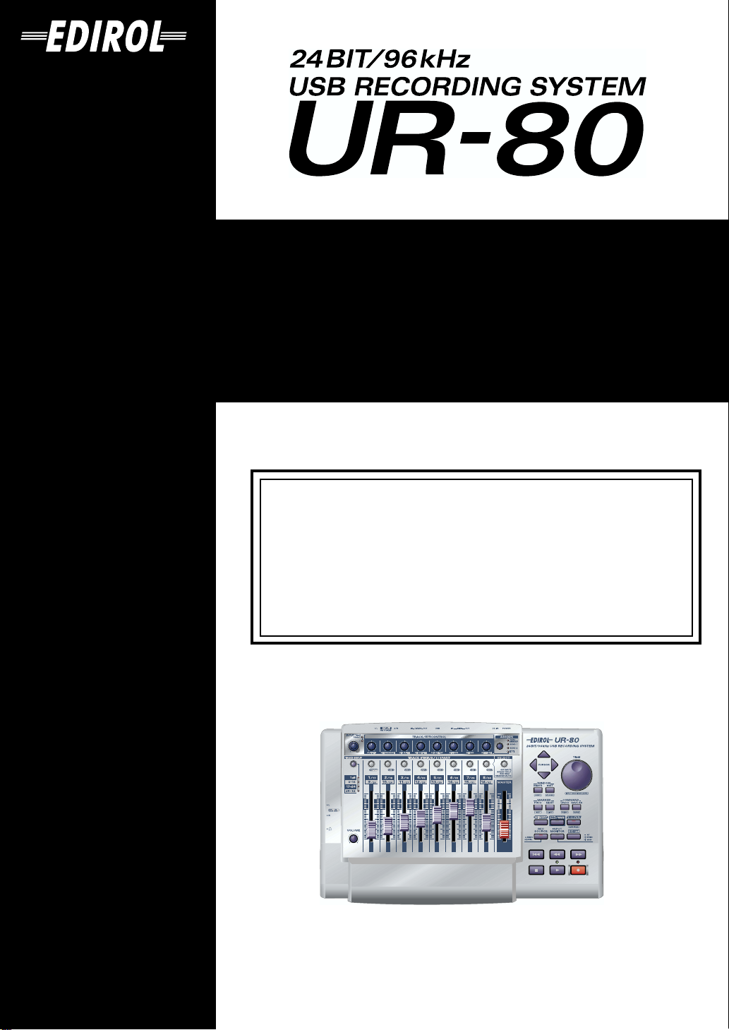
Thank you for purchasing the USB Recording System UR-80.
Before using this unit, carefully read the sections entitled: “USING
THE UNIT SAFELY” and “IMPORTANT NOTES” (OWNER’S
MANUAL pp. 2–4). These sections provide important information
concerning the proper operation of the unit. Additionally, in order
to feel assured that you have gained a good grasp of every feature
provided by your new unit, Owner’s manual should be read in its
entirety. The manual should be saved and kept on hand as a
convenient reference.
Copyright © 2003 ROLAND CORPORATION
All rights reserved. No part of this publication may be reproduced in
any form without the written permission of ROLAND CORPORATION.
USING THE UNIT SAFELY
Used for instructions intended to alert
the user to the risk of death or severe
injury should the unit be used
improperly.
Used for instructions intended to alert
the user to the risk of injury or material
damage should the unit be used
improperly.
* Material damage refers to damage or
other adverse effects caused with
respect to the home and all its
furnishings, as well to domestic
animals or pets.
001
• Before using this unit, make sure to read the
instructions below, and the Owner’s Manual.
................................................................................................
002c
• Do not open (or modify in any way) the unit or its
AC adaptor.
................................................................................................
003
• Do not attempt to repair the unit, or replace parts
within it (except when this manual provides
specific instructions directing you to do so). Refer
all servicing to your retailer, the nearest Roland
Service Center, or an authorized Roland
distributor, as listed on the “Information” page.
................................................................................................
004
• Never use or store the unit in places that are:
• Subject to temperature extremes (e.g., direct
sunlight in an enclosed vehicle, near a heating
duct, on top of heat-generating equipment); or
are
• Damp (e.g., baths, washrooms, on wet floors); or
are
• Humid; or are
• Exposed to rain; or are
• Dusty; or are
• Subject to high levels of vibration.
................................................................................................
007
• Make sure you always have the unit placed so it is
level and sure to remain stable. Never place it on
stands that could wobble, or on inclined surfaces.
................................................................................................
The symbol alerts the user to important instructions
or warnings.The specific meaning of the symbol is
determined by the design contained within the
triangle. In the case of the symbol at left, it is used for
general cautions, warnings, or alerts to danger.
The symbol alerts the user to items that must never
be carried out (are forbidden). The specific thing that
must not be done is indicated by the design contained
within the circle. In the case of the symbol at left, it
means that the unit must never be disassembled.
The ● symbol alerts the user to things that must be
carried out. The specific thing that must be done is
indicated by the design contained within the circle. In
the case of the symbol at left, it means that the powercord plug must be unplugged from the outlet.
008c
• Be sure to use only the AC adaptor supplied with
the unit. Also, make sure the line voltage at the
installation matches the input voltage specified on
the AC adaptor’s body. Other AC adaptors may
use a different polarity, or be designed for a
different voltage, so their use could result in
damage, malfunction, or electric shock.
................................................................................................
009
• Do not excessively twist or bend the power cord,
nor place heavy objects on it. Doing so can damage
the cord, producing severed elements and short
circuits. Damaged cords are fire and shock
hazards!
................................................................................................
010
• This unit, either alone or in combination with an
amplifier and headphones or speakers, may be
capable of producing sound levels that could cause
permanent hearing loss. Do not operate for a long
period of time at a high volume level, or at a level
that is uncomfortable. If you experience any
hearing loss or ringing in the ears, you should
immediately stop using the unit, and consult an audiologist.
................................................................................................
011
• Do not allow any objects (e.g., flammable material,
coins, pins); or liquids of any kind (water, soft
drinks, etc.) to penetrate the unit.
................................................................................................
2
012c
• Immediately turn the power off, remove the AC
adaptor from the outlet, and request servicing by
your retailer, the nearest Roland Service Center, or
an authorized Roland distributor, as listed on the
“Information” page when:
• The AC adaptor or the power-supply cord has
been damaged; or
• If smoke or unusual odor occurs
• Objects have fallen into, or liquid has been
spilled onto the unit; or
• The unit has been exposed to rain (or otherwise
has become wet); or
• The unit does not appear to operate normally or
exhibits a marked change in performance.
................................................................................................
013
• In households with small children, an adult should
provide supervision until the child is capable of
following all the rules essential for the safe
operation of the unit.
................................................................................................
014
• Protect the unit from strong impact.
(Do not drop it!)
................................................................................................
015
• Do not force the unit’s power-supply cord to share
an outlet with an unreasonable number of other
devices. Be especially careful when using extension
cords—the total power used by all devices you
have connected to the extension cord’s outlet must
never exceed the power rating (watts/amperes) for
the extension cord. Excessive loads can cause the
insulation on the cord to heat up and eventually
melt through.
................................................................................................
016
• Before using the unit in a foreign country, consult
with your retailer, the nearest Roland Service
Center, or an authorized Roland distributor, as
listed on the “Information” page.
................................................................................................
023
• DO NOT play a CD-ROM disc on a conventional
audio CD player. The resulting sound may be of a
level that could cause permanent hearing loss.
Damage to speakers or other system components
may result.
................................................................................................
101b
• The unit and the AC adaptor should be located so
their location or position does not interfere with
their proper ventilation.
................................................................................................
102d
• Always grasp only the output plug or the body of
the AC adaptor when plugging into, or
unplugging from, this unit or an outlet.
................................................................................................
103b
• At regular intervals, you should unplug the AC
adaptor and clean it by using a dry cloth to wipe
all dust and other accumulations away from its
prongs. Also, disconnect the power plug from the
power outlet whenever the unit is to remain
unused for an extended period of time. Any
accumulation of dust between the power plug and
the power outlet can result in poor insulation and
lead to fire.
................................................................................................
104
• Try to prevent cords and cables from becoming
entangled. Also, all cords and cables should be
placed so they are out of the reach of children.
................................................................................................
106
• Never climb on top of, nor place heavy objects on
the unit.
................................................................................................
107d
• Never handle the AC adaptor body, or its output
plugs, with wet hands when plugging into, or
unplugging from, an outlet or this unit.
................................................................................................
108b
• Before moving the unit, disconnect the AC adaptor
and all cords coming from external devices.
................................................................................................
109b
• Before cleaning the unit, turn off the power and
unplug the AC adaptor from the outlet.
................................................................................................
110b
• Whenever you suspect the possibility of lightning
in your area, disconnect the AC adaptor from the
outlet.
................................................................................................
118
• Should you remove the optical connector caps,
make sure to put them in a safe place out of
children's reach, so there is no chance of them
being swallowed accidentally.
................................................................................................
120
• Always turn the phantom power off when
connecting any device other than condenser
microphones that require phantom power.
You risk causing damage if you mistakenly supply
phantom power to dynamic microphones, audio
playback devices, or other devices that don't
require such power. Be sure to check the specifications of any microphone you intend to use by
referring to the manual that came with it.
(This instrument's phantom power: DC 48 V DC,
10 mA Max)
................................................................................................
3

IMPORTANT NOTES
291a
In addition to the items listed under “USING THE UNIT SAFELY” on page 2, please read and observe the
following:
Power Supply
301
• Do not use this unit on the same power circuit with any
device that will generate line noise (such as an electric
motor or variable lighting system).
302
• The AC adaptor will begin to generate heat after long
hours of consecutive use. This is normal, and is not a cause
for concern.
307
• Before connecting this unit to other devices, turn off the
power to all units. This will help prevent malfunctions
and/or damage to speakers or other devices.
Placement
351
• Using the unit near power amplifiers (or other equipment
containing large power transformers) may induce hum. To
alleviate the problem, change the orientation of this unit; or
move it farther away from the source of interference.
352a
• This device may interfere with radio and television
reception. Do not use this device in the vicinity of such
receivers.
352b
• Noise may be produced if wireless communications
devices, such as cell phones, are operated in the vicinity of
this unit. Such noise could occur when receiving or initiating a call, or while conversing. Should you experience
such problems, you should relocate such wireless devices
so they are at a greater distance from this unit, or switch
them off.
354a
• Do not expose the unit to direct sunlight, place it near
devices that radiate heat, leave it inside an enclosed
vehicle, or otherwise subject it to temperature extremes.
Excessive heat can deform or discolor the unit.
355b
• When moved from one location to another where the
temperature and/or humidity is very different, water
droplets (condensation) may form inside the unit. Damage
or malfunction may result if you attempt to use the unit in
this condition. Therefore, before using the unit, you must
allow it to stand for several hours, until the condensation
has completely evaporated.
Maintenance
401a
• For everyday cleaning wipe the unit with a soft, dry cloth
or one that has been slightly dampened with water. To
remove stubborn dirt, use a cloth impregnated with a mild,
non-abrasive detergent. Afterwards, be sure to wipe the
unit thoroughly with a soft, dry cloth.
402
• Never use benzine, thinners, alcohol or solvents of any
kind, to avoid the possibility of discoloration and/or deformation.
Repairs and Data
452
• Please be aware that all data contained in the unit’s
memory may be lost when the unit is sent for repairs.
Important data should always be backed up
MIDI device (e.g., a sequencer)
paper (when possible). During repairs, due care is taken to
avoid the loss of data. However, in certain cases (such as
when circuitry related to memory itself is out of order), we
regret that it may not be possible to restore the data, and
Roland assumes no liability concerning such loss of data.
, or written down on
in another
Additional Precautions
551
• Please be aware that the contents of memory can be
irretrievably lost as a result of a malfunction, or the
improper operation of the unit. To protect yourself against
the risk of loosing important data, we recommend that you
periodically save a backup copy of important data you
have stored in the unit’s memory in another MIDI device
(e.g., a sequencer)
552
• Unfortunately, it may be impossible to restore the contents
of data that was stored
sequencer)
assumes no liability concerning such loss of data.
553
• Use a reasonable amount of care when using the unit’s
buttons, sliders, or other controls; and when using its jacks
and connectors. Rough handling can lead to malfunctions.
556
• When connecting / disconnecting all cables, grasp the
connector itself—never pull on the cable. This way you will
avoid causing shorts, or damage to the cable’s internal
elements.
558a
• To avoid disturbing your neighbors, try to keep the unit’s
volume at reasonable levels. You may prefer to use
headphones, so you do not need to be concerned about
those around you (especially when it is late at night).
559a
• When you need to transport the unit, package it in the box
(including padding) that it came in, if possible. Otherwise,
you will need to use equivalent packaging materials.
once it has been lost. Roland Corporation
in another MIDI device (e.g., a
4

562
• Use a cable from Roland to make the connection. If using
some other make of connection cable, please note the
following precautions.
• Some connection cables contain resistors. Do not use
cables that incorporate resistors for connecting to this
unit. The use of such cables can cause the sound level to
be extremely low, or impossible to hear. For information on cable specifications, contact the manufacturer of the cable.
564
• Before you open the included CD-ROM, you must read the
“license agreement.” Opening the CD-ROM will be taken
to mean your acceptance of the license agreement.
Handling CD-ROMs
801
• Avoid touching or scratching the shiny underside
(encoded surface) of the disc. Damaged or dirty CD-ROM
discs may not be read properly. Keep your discs clean
using a commercially available CD cleaner.
Copyright
851
• Unauthorized recording, distribution, sale, lending, public
performance, broadcasting, or the like, in whole or in part,
of a work (musical composition, video, broadcast, public
performance, or the like) whose copyright is held by a third
party is prohibited by law.
852a
• When exchanging audio signals through a digital
connection with an external instrument, this unit can
perform recording without being subject to the restrictions
of the Serial Copy Management System (SCMS). This is
because the unit is intended solely for musical production,
and is designed not to be subject to restrictions as long as it
is used to record works (such as your own compositions)
that do not infringe on the copyrights of others. (SCMS is a
feature that prohibits second-generation and later copying
through a digital connection. It is built into MD recorders
and other consumer digital-audio equipment as a
copyright-protection feature.)
853
• Do not use this unit for purposes that could infringe on a
copyright held by a third party. We assume no responsibility whatsoever with regard to any infringements of
third-party copyrights arising through your use of this
unit.
204
* Microsoft and Windows are registered trademarks
of Microsoft Corporation.
206e
* Screen shots in this documents are reprinted with
permission from Microsoft Corporation.
206j
* Windows® is known officially as: “Microsoft®
Windows® operating system.”
207
* Apple and Macintosh are registered trademark of
Apple Computer, Inc.
209
* MacOS is a trademark of Apple Computer, Inc.
220
* All product names mentioned in this document are
trademarks or registered trademarks of their
respective owners.
231
* OMS is a registered trademark of Opcode Systems,
Inc.
232
* FreeMIDI is a trademark of Mark of the Unicorn,
Inc.
233
* VST is a trademark of Steinberg Media Technologies
AG.
5

Contents
IMPORTANT NOTES................................................................4
Contents ...................................................................................6
Main Features of the UR-80...................................................16
Names of Things and What They Do....................................17
Main panel ..........................................................................................................................17
Track Control section.............................................................................................18
Master Control section...........................................................................................21
Audio Control section............................................................................................23
Rear panel............................................................................................................................24
Side panel............................................................................................................................26
Basic operation......................................27
Basic connections and settings...........................................28
Basic connections ...............................................................................................................28
MIDI flow.................................................................................................................28
Audio flow (block diagram)..................................................................................29
Input/output devices........................................................................................................30
Two MIDI ports..................................................................................................................31
Controlling your software.....................................................32
Switching memory sets.....................................................................................................32
SONAR................................................................................................................................33
Settings in SONAR .................................................................................................33
Functions assigned to the controllers ..................................................................34
Cubase SX............................................................................................................................36
Settings in Cubase SX.............................................................................................36
Functions assigned to the controllers ..................................................................37
Cubase VST.........................................................................................................................39
Settings in Cubase VST (Windows users)...........................................................39
Settings in Cubase VST (Macintosh users)..........................................................40
Functions assigned to the controllers ..................................................................41
Logic.....................................................................................................................................43
Settings in Logic......................................................................................................43
Functions assigned to the controllers ..................................................................44
Pro Tools LE, Digital Performer 3....................................................................................47
Settings in ProTools LE..........................................................................................47
Settings in Digital Performer ................................................................................47
Functions assigned to the controllers ..................................................................48
Reason..................................................................................................................................51
MIDI port settings ..................................................................................................51
Settings for reason transport and MIDI IN DEVICE.........................................51
Controlling the tempo of the song .......................................................................52
MIDI Remote Mapping settings...........................................................................52
Functions assigned to the controllers ..................................................................53
Roland MCR-8 compatible applications.........................................................................55
6

Recording audio.....................................................................57
Basic use ..............................................................................................................................57
Recording guitar or bass...................................................................................................58
Recording from a mic........................................................................................................59
Recording a keyboard .......................................................................................................60
Recording from an audio device......................................................................................61
Digitally recording from a CD/MD/DAT.....................................................................62
Recording the output of the UR-80 on a digital device................................................63
Adjusting the audio latency .............................................................................................64
Using ASIO Direct Monitor..............................................................................................65
Advanced operation...............................67
Synth Edit mode.....................................................................68
Track faders.............................................................................................................68
Assign button (ASSIGN) .......................................................................................68
Track control knobs (TRACK/HQ CONTROL) ................................................69
Track group select button (TRACK GROUP).....................................................69
Track status buttons (TRACK STATUS/HQ PART).........................................69
Parameter list...........................................................................................................70
V-LINK mode ..........................................................................71
Parameter list...........................................................................................................71
Controllers used in V-LINK mode.......................................................................72
UR-80 Editor...........................................................................73
Starting up UR-80 Editor ..................................................................................................73
MIDI Port settings..............................................................................................................74
UR-80 Editor window .......................................................................................................75
Main window..........................................................................................................75
Controller settings..............................................................................................................77
MIDI messages that you can assign to controllers.............................................77
Assigning a MIDI message....................................................................................78
Checking the assigned MIDI messages...............................................................79
Memory Set Initial Message .............................................................................................80
Specifying the Memory Set Initial Message........................................................80
Enabling the Memory Set Initial Message...........................................................80
Exchanging data with the UR-80.....................................................................................81
Transmitting to the UR-80.....................................................................................81
Receiving from the UR-80 .....................................................................................81
Saving or loading in SMF format.....................................................................................82
Saving a memory set in SMF format....................................................................82
Loading a memory set from a SMF file...............................................................82
System settings...................................................................................................................82
Bezeichnungen und Funktionen ..........................................83
Hauptbedienfeld................................................................................................................83
Abschnitt Track Control ........................................................................................84
Abschnitt Master Control......................................................................................87
Abschnitt Audio Control.......................................................................................89
Rückseite .............................................................................................................................90
Seitliches Bedienfeld..........................................................................................................92
7

Grundlegende Bedienung.......................93
Grundlegende Anschlüsse und Einstellungen...................94
Grundlegende Anschlüsse................................................................................................94
MIDI-Datenfluss .....................................................................................................94
Audiodatenfluss (Blockdiagramm)......................................................................95
Eingabe-/Ausgabegeräte..................................................................................................96
Zwei MIDI-Anschlüsse .....................................................................................................97
Steuerung Ihrer Software......................................................98
Umschalten von Memory Sets .........................................................................................98
SONAR................................................................................................................................99
Einstellungen in SONAR.......................................................................................99
Den Controllern zugewiesene Funktionen.......................................................100
Cubase SX..........................................................................................................................102
Einstellungen in Cubase SX ................................................................................102
Den Controllern zugewiesene Funktionen.......................................................103
Cubase VST.......................................................................................................................105
Einstellungen in Cubase VST (Windows-Anwender).....................................105
Einstellungen in Cubase VST (Macintosh-Anwender) ...................................106
Den Controllern zugewiesene Funktionen.......................................................107
Logic...................................................................................................................................109
Einstellungen in Logic .........................................................................................109
Den Controllern zugewiesene Funktionen.......................................................110
Pro Tools LE, Digital Performer 3..................................................................................113
Einstellungen in Pro Tools LE.............................................................................113
Einstellungen in Digital Performer....................................................................113
Den Controllern zugewiesene Funktionen.......................................................114
Reason................................................................................................................................117
Einstellungen für den MIDI-Anschluss.............................................................117
Einstellungen für Reason-Transport und MIDI-IN-Gerät..............................117
Tempo des Songs steuern....................................................................................118
Einstellungen für MIDI-Remote-Mapping .......................................................118
Den Controllern zugewiesene Funktionen.......................................................119
Mit Roland MCR-8 kompatible Anwendungen..........................................................121
Aufnahme von Audio...........................................................123
Grundlegende Verwendung ..........................................................................................123
Aufnahme von Gitarre oder Bass..................................................................................124
Aufnahme über ein Mikrofon ........................................................................................125
Aufnahme von einem Keyboard ...................................................................................126
Aufnahme von einem Audiogerät.................................................................................127
Digitalaufnahme von einem CD-/MD-/DAT-Gerät..................................................128
Aufnahme der Ausgabe des UR-80 auf einem Digitalgerät......................................129
Änderung der Audiolatenz............................................................................................130
Verwendung des ASIO Direct Monitor........................................................................131
8

Erweiterte Bedienung........................... 133
Synth-Edit-Modus................................................................134
Track Fader............................................................................................................134
Schaltfläche Assign (ASSIGN)............................................................................134
Track-Steuerungsschaltknöpfe (TRACK/HQ CONTROL)............................135
Track-Group-Auswahlschaltfläche (TRACK GROUP)...................................135
Track-Status-Schaltflächen (TRACK STATUS/HQ PART)............................135
Parameterliste........................................................................................................136
V-LINK-Modus......................................................................137
Parameterliste........................................................................................................137
Im V-LINK-Modus verwendete Controller......................................................138
UR-80 Editor.........................................................................139
Starten des UR-80 Editor.................................................................................................139
Einstellungen für den MIDI-Anschluss........................................................................140
UR-80 Editor-Fenster.......................................................................................................141
Hauptfenster..........................................................................................................141
Controller-Einstellungen.................................................................................................143
MIDI-Nachrichten, die Sie Controllern zuweisen können.............................143
Zuweisung einer MIDI-Nachricht......................................................................144
Prüfung der zugewiesenen MIDI-Nachrichten................................................145
Memory Set Initial Message ...........................................................................................146
Festlegen der Memory Set Initial Message .......................................................146
Aktivierung der Memory Set Initial Message ..................................................146
Austausch von Daten mit dem UR-80 ..........................................................................147
Übertragung an das UR-80..................................................................................147
Empfang vom UR-80............................................................................................147
Sichern oder Laden im SMF-Format.............................................................................148
Sichern eines Memory Sets im SMF-Format.....................................................148
Laden eines Memory Sets von einer SMF-Datei..............................................148
Systemeinstellungen........................................................................................................148
Définitions ............................................................................149
Panneau principal............................................................................................................149
Section Track Control...........................................................................................150
Section Master Control.........................................................................................153
Section Audio Control .........................................................................................155
Face arrière........................................................................................................................156
Face latérale.......................................................................................................................158
Fonctionnement de base....................... 159
Connexions et réglages de base........................................160
Connexions de base .........................................................................................................160
Flux MIDI...............................................................................................................160
Flux audio (schéma).............................................................................................161
Périphériques d’entrée/sortie........................................................................................162
Deux ports MIDI ..............................................................................................................163
9

Contrôle de votre logiciel....................................................164
Commutation des jeux de sons......................................................................................164
SONAR..............................................................................................................................165
Réglages de SONAR.............................................................................................165
Fonctions affectées aux contrôleurs...................................................................166
Cubase SX..........................................................................................................................168
Réglages de Cubase SX........................................................................................168
Fonctions affectées aux contrôleurs...................................................................169
Cubase VST.......................................................................................................................171
Réglages de Cubase VST (utilisateurs de Windows) ......................................171
Réglages de Cubase VST (utilisateurs de Macintosh).....................................172
Fonctions affectées aux contrôleurs...................................................................173
Logic...................................................................................................................................175
Réglages de Logic.................................................................................................175
Fonctions affectées aux contrôleurs...................................................................176
Pro Tools LE, Digital Performer 3..................................................................................179
Réglages de ProTools LE .....................................................................................179
Réglages de Digital Performer............................................................................179
Fonctions affectées aux contrôleurs...................................................................180
Reason................................................................................................................................183
Paramètres du port MIDI ....................................................................................183
Réglages du transport Reason et de MIDI IN DEVICE ..................................183
Contrôle du tempo de la chanson ......................................................................184
Réglages de MIDI Remote Mapping..................................................................184
Fonctions affectées aux contrôleurs...................................................................185
Applications compatibles avec Roland MCR-8...........................................................187
Enregistrement audio..........................................................189
Utilisation de base............................................................................................................189
Enregistrement d’une guitare ou d’une basse.............................................................190
Enregistrement avec un micro .......................................................................................191
Enregistrement avec un clavier......................................................................................192
Enregistrement d'un appareil audio .............................................................................193
Enregistrement numérique à partir de CD/MD/DAT..............................................194
Enregistrement de l’UR-80 vers un appareil numérique...........................................195
Réglage de la latence audio ............................................................................................196
Utilisation d’ASIO Direct Monitor ................................................................................197
Fonctionnement avancé........................ 199
Mode Edition Synth .............................................................200
Commandes d’atténuation Track.......................................................................200
Bouton d’affectation (ASSIGN) .........................................................................200
Boutons de réglage de pistes (TRACK/HQ CONTROL)...............................201
Bouton de sélection du groupe de pistes (TRACK GROUP) .........................201
Boutons Track Status (TRACK STATUS/HQ PART) ....................................201
Liste des paramètres.............................................................................................202
Mode V-LINK.........................................................................203
Liste des paramètres.............................................................................................203
Contrôleurs utilisés en mode V-LINK...............................................................204
10

UR-80 Editor.........................................................................205
Démarrage de UR-80 Editor...........................................................................................205
Paramètres du Port MIDI................................................................................................206
Fenêtre UR-80 Editor.......................................................................................................207
Fenêtre principale.................................................................................................207
Réglages des contrôleurs.................................................................................................209
Messages MIDI que vous pouvez affecter aux contrôleurs............................209
Affectation d’un message MIDI..........................................................................210
Vérification des messages MIDI affectés...........................................................211
Memory Set Initial Message ...........................................................................................212
Spécification du Memory Set Initial Message ..................................................212
Activation du Memory Set Initial Message ......................................................212
Echange de données avec l’UR-80.................................................................................213
Transmission vers l’UR-80 ..................................................................................213
Réception à partir de l’UR-80..............................................................................213
Sauvegarde ou chargement au format SMF.................................................................214
Sauvegarder un jeu de sons au format SMF.....................................................214
Chargement d’un jeu de sons à partir d’un fichier SMF.................................214
Paramètres système .........................................................................................................214
Parti e relative funzioni........................................................215
Pannello principale.........................................................................................................215
Sezione Track Control..........................................................................................216
Sezione Master Control........................................................................................219
Sezione Audio Control.........................................................................................221
Pannello posteriore..........................................................................................................222
Pannello laterale...............................................................................................................224
Nozioni di base....................................225
Nozioni di base e impostazioni...........................................226
Collegamenti di base .......................................................................................................226
Dati MIDI...............................................................................................................226
Dati audio (schema di flusso) .............................................................................227
Periferiche di ingresso/uscita ........................................................................................228
Due porte MIDI................................................................................................................229
Utilizzo del software ............................................................230
Cambio di patch di memoria..........................................................................................230
SONAR..............................................................................................................................231
Impostazioni in SONAR......................................................................................231
Funzioni assegnate ai controlli ...........................................................................232
Cubase SX..........................................................................................................................234
Impostazioni in Cubase SX..................................................................................234
Funzioni assegnate ai controlli ...........................................................................235
Cubase VST.......................................................................................................................237
Impostazioni in Cubase VST (utenti Windows)...............................................237
Impostazioni in Cubase VST (utenti Macintosh).............................................238
Funzioni assegnate ai controlli ...........................................................................239
Logic...................................................................................................................................241
Impostazioni in Logic...........................................................................................241
Funzioni assegnate ai controlli ...........................................................................242
11

Pro Tools LE, Digital Performer 3..................................................................................245
Impostazioni in ProTools LE...............................................................................245
Impostazioni in Digital Performer.....................................................................245
Funzioni assegnate ai controlli ...........................................................................246
Reason................................................................................................................................249
Impostazioni della porta MIDI...........................................................................249
Impostazioni per il trasporto e MIDI IN DEVICE in Reason.........................249
Controllo del tempo del brano............................................................................250
Impostazioni MIDI Remote Mapping ...............................................................250
Funzioni assegnate ai controlli ...........................................................................251
Applicazioni Roland MCR-8 compatibili.....................................................................253
Registrazione audio.............................................................255
Nozioni fondamentali .....................................................................................................255
Registrazione della chitarra o del basso .......................................................................256
Registrazione da un microfono......................................................................................257
Registrazione di una tastiera..........................................................................................258
Registrazione da un dispositivo audio .........................................................................259
Registrazione digitale da CD/MD/DAT.....................................................................260
Registrazione dell'output dell'UR-80 su un dispositivo digitale ..............................261
Regolazione della latenza audio....................................................................................262
Uso di ASIO Direct Monitor...........................................................................................263
Operazioni avanzate............................265
Modalità Synth Edit..............................................................266
Fader delle tracce..................................................................................................266
Pulsante di assegnazione (ASSIGN)..................................................................266
Manopole di controllo delle tracce (TRACK/HQ CONTROL).....................267
Pulsante di selezione del gruppo di tracce (TRACK GROUP) ......................267
Pulsanti dello stato delle tracce (TRACK STATUS/HQ PART)....................267
Elenco dei parametri ............................................................................................268
Modalità V-LINK ...................................................................269
Elenco dei parametri ............................................................................................269
Controlli utilizzati in modalità V-LINK............................................................270
UR-80 Editor.........................................................................271
Avvio di UR-80 Editor.....................................................................................................271
Impostazioni della porta MIDI ......................................................................................272
Finestra UR-80 Editor......................................................................................................273
Finestra principale................................................................................................273
Impostazioni dei controlli...............................................................................................275
Messaggi MIDI che possono essere assegnati ai controlli..............................275
Assegnazione di un messaggio MIDI................................................................276
Controllo dei messaggi MIDI assegnati ............................................................277
Messaggio iniziale per patch di memoria ....................................................................278
Indicazione di un messaggio iniziale per patch di memoria .........................278
Attivazione del messaggio iniziale per patch di memoria.............................278
Scambio di dati con l'UR-80............................................................................................279
Invio di dati all'UR-80..........................................................................................279
Ricezione di dati dall'UR-80................................................................................279
12

Salvare o aprire in formato SMF....................................................................................280
Salvare un patch di memoria in formato SMF .................................................280
Aprire un patch di memoria da un file SMF ....................................................280
Impostazioni di sistema ..................................................................................................280
Denominaciones de los elementos y las funciones que
desempeñan.........................................................................281
Panel principal..................................................................................................................281
Sección de control de pistas ................................................................................282
Sección de control máster (Master Control) .....................................................285
Sección de control de audio ................................................................................287
Panel posterior..................................................................................................................288
Panel lateral.......................................................................................................................290
Funcionamiento básico.........................291
Conexiones y configuración básicas.................................292
Conexiones básicas ..........................................................................................................292
Flujo MIDI..............................................................................................................292
Flujo de audio (diagrama de bloques)...............................................................293
Aparatos de entrada/salida ...........................................................................................294
Dos puertos MIDI ............................................................................................................295
Control del software............................................................296
Conmutación de conjuntos de memoria.......................................................................296
SONAR..............................................................................................................................297
Configuración en SONAR...................................................................................297
Funciones asignadas a los controladores..........................................................298
Cubase SX..........................................................................................................................300
Configuración en Cubase SX...............................................................................300
Funciones asignadas a los controladores..........................................................301
Cubase VST.......................................................................................................................303
Configuración en Cubase VST (usuarios de Windows)..................................303
Configuración en Cubase VST (usuarios de Macintosh)................................304
Funciones asignadas a los controladores..........................................................305
Logic...................................................................................................................................307
Configuración en Logic........................................................................................307
Funciones asignadas a los controladores..........................................................308
Pro Tools LE, Digital Performer 3..................................................................................311
Configuración en ProTools LE............................................................................311
Configuración en Digital Performer ..................................................................311
Funciones asignadas a los controladores..........................................................312
Reason................................................................................................................................315
Configuración de puertos MIDI.........................................................................315
Configuración para las opciones de reproducción de Reason y el aparato de
entrada MIDI.........................................................................................................315
Control del tempo de la canción.........................................................................316
Configuración de MIDI Remote Mapping........................................................316
Funciones asignadas a los controladores..........................................................317
Aplicaciones compatibles con el MCR-8 de Roland ...................................................319
13

Grabación de audio .............................................................321
Uso básico .........................................................................................................................321
Grabación de una guitarra o un bajo.............................................................................322
Grabación desde un micrófono......................................................................................323
Grabación de un teclado .................................................................................................324
Grabación de un aparato de audio................................................................................325
Grabación digital desde un CD/MD/DAT .................................................................326
Grabación de la salida de la unidad UR-80 en un aparato digital............................327
Ajuste del tiempo de recuperación de datos de audio...............................................328
Utilización de ASIO Direct Monitor..............................................................................329
Funcionamiento avanzado ...................331
Modo Synth Edit (Editar sintetizador)................................332
Atenuadores de pistas..........................................................................................332
Botón de asignación (ASSIGN)...........................................................................332
Controles giratorios de pistas (TRACK/HQ CONTROL)..............................333
Botón de selección de grupo de pistas (TRACK GROUP)..............................333
Botones de estado de pista (TRACK STATUS/HQ PART)............................333
Lista de parámetros..............................................................................................334
Modo V-LINK ........................................................................335
Lista de parámetros..............................................................................................335
Controles utilizados en el modo V-LINK..........................................................336
UR-80 Editor.........................................................................337
Inicio de UR-80 Editor.....................................................................................................337
Configuración de puertos MIDI.....................................................................................338
Ventana de UR-80 Editor................................................................................................339
Ventana principal .................................................................................................339
Configuración de controladores ....................................................................................341
Mensajes MIDI que pueden asignarse a controladores ..................................341
Asignación de un mensaje MIDI........................................................................342
Comprobación del mensaje MIDI asignado .....................................................343
Mensaje inicial de un conjunto de memoria ................................................................344
Especificación del mensaje inicial de un conjunto de memoria.....................344
Habilitación del mensaje inicial de un conjunto de memoria........................344
Intercambio de datos con la unidad UR-80..................................................................345
Transmisión a la unidad UR-80..........................................................................345
Recepción desde la unidad UR-80......................................................................345
Gaurdar o cargar en formato SMF.................................................................................346
Guardar un conjunto de memoria en formato SMF........................................346
Cargar un conjunto de memoria de un archivo SMF......................................346
Configuración del sistema..............................................................................................346
14

Appendices ..........................................347
System-related settings ......................................................348
Restoring the factory settings (Factory Reset) .............................................................348
Switching the Driver Mode ............................................................................................348
Memory sets.........................................................................349
PRESET MEMORY (SONAR) PARAMETER LIST.....................................................349
USR1 MEMORY (Cubase SX) PARAMETER LIST.....................................................352
USR2 MEMORY (Cubase VST) PARAMETER LIST ..................................................355
USR3 MEMORY (Logic) PARAMETER LIST..............................................................358
USR4 MEMORY (Pro Tools LE / Digital Performer) PARAMETER LIST..............361
USR5 MEMORY (Reason) PARAMETER LIST...........................................................365
USR6 MCR-8 Mode4-A/1-8 PARAMETER LIST........................................................368
USR7 MCR-8 Mode4-B/9-16 PARAMETER LIST.......................................................370
Troubleshooting...................................................................372
Can’t use the START/STOP button to make Reason play/stop...................372
When using Logic, can’t use the track control knobs to edit parameters.....372
Can’t control Hyper Canvas (or your MIDI sound module) in Synth Edit
mode.......................................................................................................................373
Can only control a specific Part of Hyper Canvas (or your MIDI sound
module) in Synth Edit mode...............................................................................373
Operating system becomes unstable .................................................................373
Can’t hear sound from the computer ................................................................373
Can't record/play MIDI.......................................................................................374
Sound from devices connected to the input jack is not heard in the
headphones............................................................................................................374
Volume from a device connected to the input jacks is too low......................374
The sound of a device connected to the input jack is distorted.....................374
Noise is heard during audio playback ..............................................................375
Sound is interrupted during audio playback...................................................376
Digitally recorded sound is distorted, is at the wrong pitch, or-contains noise
.................................................................................................................................378
Playback or recording halts midway through, and then becomes impossible
.................................................................................................................................378
Recording produces a silent (blank) file............................................................378
A loud buzz is present in the guitar signal.......................................................378
MIDI implementation............................................................379
Specifications.......................................................................386
UR-80: USB Recording System ...........................................................................386
Index......................................................................................387
15

Main Features of the UR-80
The UR-80 combines two major types of functionality; a Controller that uses MIDI messages to
control your sequencer software or synthesizer, and a USB Audio Interface that lets you record and
play back audio on your computer.
It is the ideal partner for your DAW (Digital Audio Workstation) software, and will let you perform
music production operations such as recording, playback, and mixing faster and more efficiently.
Fully assignable design
The UR-80 is fully assignable. You can assign any type of MIDI message—control changes, RPN,
NRPN, system exclusive—to the controllers. Using the dedicated UR-80 Editor software you can
freely change the MIDI message assignments. Customized assignments can be stored in the
UR-80’s seven user memory sets.
USB interface with 24-bit/96 kHz support
The audio interface is designed for high audio quality, and supports up to 24-bit/96 kHz. XLR
jacks, mic preamps, and phantom power are provided, allowing you to use condenser mics for
serious recording.
A high-impedance switch lets you connect a guitar directly, and both optical and coaxial type
digital input/output jacks are provided.
Comes with “Hyper Canvas” software synthesizer
The GM2-compatible Hyper Canvas software synthesizer is included, providing 256 sounds +
9 drum sets. You can use it in conjunction with your DXi- or VSTi-compatible software to start
producing music immediately.
MIDI interface functionality
The UR-80 includes a USB MIDI interface with FPT support. Even when the UR-80 is not connected
to your computer via USB, you can use it as a MIDI controller via its MIDI connectors.
V-LINK support
The UR-80 supports V-LINK, and can be used in conjunction with video devices such as the Edirol
DV-7PR for video-integrated performances.
16
Español Italiano Français Deutsch English
Names of Things and What They Do
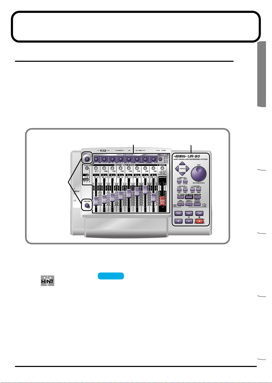
Main panel
The UR-80’s main panel is divided into the Track Control section, Master Control section, and
Audio Control section.
The Track Control section and Master Control section provide 43 controllers to which you can
assign MIDI messages. By using these controllers in conjunction with the SHIFT button, and
including assignments to LEDs, you can assign a total of 136 different MIDI messages. Use UR-80
Editor to assign MIDI messages to controllers and to edit the assignments. UR-80 Editor is provided
on the included CD-ROM.
* For details on UR-80 Editor, refer to “UR-80 Editor (p. 73)”.
Audio Control section
• Track Control section........................p. 18
• Master Control section......................p. 21
• Audio Control section.......................p. 23
An indication of for a controller in the explanations that follow means
that you can assign a MIDI message to this controller.
Assignable
Track Control section
Master Control section
17
Names of Things and What They Do
■ Track Control section
The Track Control section lets you control the track parameters of your sequencer software. In
addition to volume and pan, you can also control parameters such as track status and effect send
level. By switching track groups you can control the parameters of up to 32 tracks.
* The content that will actually be controlled will depend on the software you are using.
Synth Edit mode or V-LINK mode, the UR-80 will operate differently than explained here.
For details, refer to “Synth Edit mode (p. 68)” or “V-LINK mode (p. 71)”.
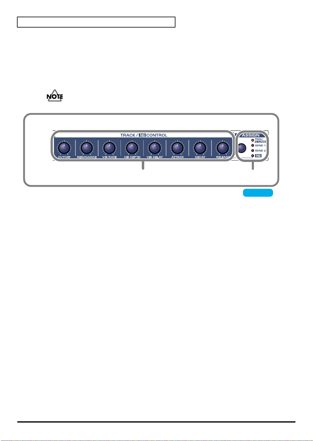
fig.track-knob
1
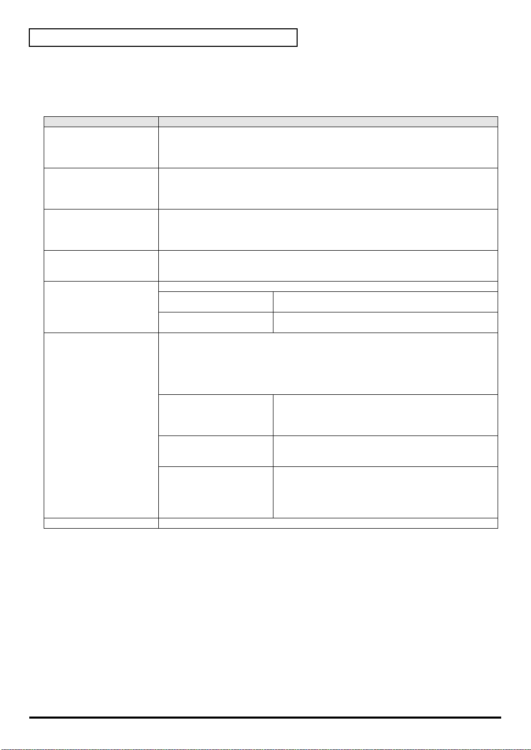
1. Track Control knobs (TRACK/HQ CONTROL).....................................................
You can assign MIDI messages to each of these eight knobs. Three different messages can be
assigned to each knob; one for each state of the Assign button (PAN, SEND 1, SEND 2). This means
that you can assign a total of 24 different messages to the Track Control knobs. Typically, you will
use these to control track panning or effect send on your sequencer software.
2. Assign button (ASSIGN)
This button switches the messages that are assigned to the track control knobs. By pressing the
Assign button you can select from these choices: PAN → SEND 1 → SEND 2.
2
Assignable
18
Español Italiano Français Deutsch English
Names of Things and What They Do
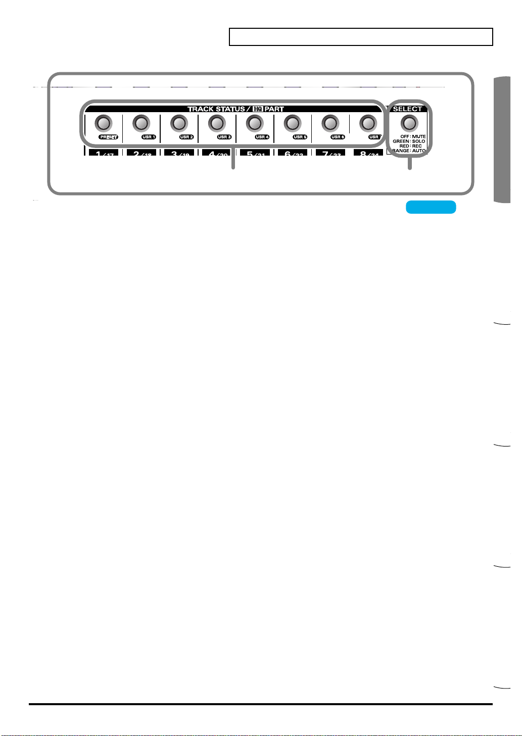
3
3. Track Status buttons (TRACK STATUS/HQ PART)..............................................
You can assign MIDI messages to each of these eight buttons. You can also assign MIDI messages
to the LED of each button, and turn the LEDs on/off from your sequencer software.
To each button and LED you can assign four different messages; one for each state of the Select
button (off, green, red, orange). This means that you can assign a total of 32 MIDI messages to the
Track Status buttons, and 32 MIDI messages to the LEDs.
Typically, you will use these buttons to switch the track status (e.g., mute, solo) on your sequencer
software.
4. Select button (SELECT)
This button switches the MIDI messages that are assigned to the Track Status buttons and their
LEDs. By pressing the Select button you can cycle through these choices: off → green → red
→ orange.
4
Assignable
19
Names of Things and What They Do
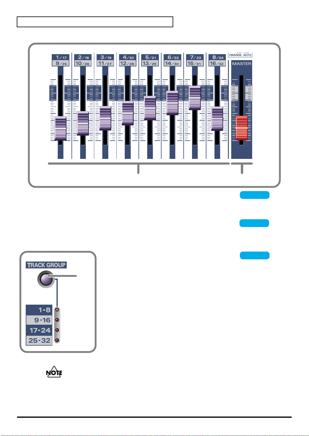
5
5. Track faders............................................................................................................
6
Assignable
You can assign MIDI messages to each of these eight faders. Typically, you will use the track faders
to control the track volume on your sequencer software.
6. Master fader (MASTER).........................................................................................
Assignable
You can assign a MIDI message to this fader. The master fader controls the master volume on your
sequencer software. The final volume of the UR-80 itself is adjusted by its output volume knob.
fig.track-ctrl
7.Track Group select button (TRACK GROUP)..........
Assignable
You can assign four MIDI messages to the Track Group select button.
7
Each time you press the button, one of the four messages will be
transmitted.
The Track Group select button switches the group of tracks on your
sequencer software whose parameters will be controlled by the track
control knobs and track faders. This means that you can use the eight
knobs and faders to control the parameters of 32 tracks.
20
Operating the Track Group select button does not switch the messages assigned to the Track
Control knobs, Track Status button, and Track Faders. The Track Group select button transmits
four different MIDI messages to your sequencer software to change the base track number on
your software.
Español Italiano Français Deutsch English
■ Master Control section
The Master Control section is where you can execute commands and control the transport on your
sequencer software. Here you can also make settings for the UR-80’s audio interface.
* The content that is controlled will depend on the software you are using.
Names of Things and What They Do
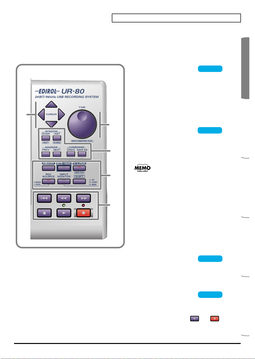
fig.master-ctrl
8
9
10
12
11
8.Cursor buttons .....................
You can assign MIDI messages to these four
buttons. Since you can also assign messages for
when the SHIFT button is being held down, a
total of eight MIDI messages can be assigned to
these four buttons.
Use the cursor buttons to switch the track that is
selected in your sequencer software or to move
the focus point.
9.TIME dial................................
You can assign one MIDI message to this dial.
Use the TIME dial to move the song location
within your sequencer software.
If you hold down the SHIFT button and turn the
TIME dial, the dial will adjust the input monitor
level. For details on input monitoring, refer to
p. 22.
Assignable
Assignable
10. Function buttons....................................................................................................
You can assign MIDI messages to these six buttons. Since you can also assign messages for when
the SHIFT button is being held down, a total of 12 MIDI messages can be assigned to these buttons.
You will typically use the function buttons to execute various commands on your sequencer
software.
11. Transport buttons..................................................................................................
You can assign MIDI messages to these six buttons. Since you can also assign messages for when
the SHIFT button is being held down, a total of 12 MIDI messages can be assigned to these buttons.
You can also assign MIDI messages to control the two LEDs located above the and
transport buttons.
These buttons are typically used to control the transport of your sequencer software.
Assignable
Assignable
21
Names of Things and What They Do
12. System Setting/Mode Select buttons
Use these buttons to switch settings and modes on the UR-80 itself.
You cannot assign MIDI messages to the System Setting/Mode Select buttons.
Button name Operation
MEMORY By holding down the MEMORY button and pressing a TRACK STATUS button you can
switch among the eight memory sets stored within the UR-80.
When you press this button, one of the TRACK STATUS button LEDs will light to indicate
the currently selected memory set.
HQ/GM2 When the HQ/GM2 button is on, the Track Control section will be in Synth Edit mode,
allowing you to control the parameters of the included software synthesizer. Press the
button once again to turn it off and return to the previous track control functions.
For details on Synth Edit mode refer to “Synth Edit mode (p. 68)”.
V-LINK When the V-LINK button is on, the Track Control section will be in V-LINK mode, allowing
you to control V-LINK compatible video devices. Press the button once again to turn it off
and return to the previous track control functions.
For details on V-LINK mode refer to “V-LINK mode (p. 71)”.
[MIDI CLK]
(SHIFT + V-LINK)
REC SOURCE Switches the input signal that is being sent via USB to the computer as the recording source.
[INPUT MONITOR LEVEL]
(SHIFT + TIME)
SHIFT Use this in conjunction with other buttons in the Master Control section.
This switches MIDI Timing Clock (F8) transmission on/off.
* When you press the SHIFT button, the LED will indicate the F8 on/off status—not the
V-LINK on/off status.
ANALOG (LED unlit):
DIGITAL (LED lit):
Selects whether the input signal from the input jacks (1/2) and digital input jack will be sent
to the headphone jack and master output jacks.
Use [SHIFT] + TIME dial to adjust the monitor level.
* Input monitoring can be switched on/off from ASIO 2.0 compliant software such as
Cubase.
* Adjusting the input monitor level will not change the recording level.
OFF (LED unlit):
STEREO (LED lit):
MONO (LED blinking):
Only the signal from the input jacks will be sent to the
computer.
Only the signal from the digital input jacks (coaxial or
optical) will be sent to the computer.
The input signal will not be output. Use this setting if you
are “thru-ing” the audio data within your computer, or if
you have connected a mixer and are using the mixer to
directly output the input signal for monitoring.
The input signal will be output in stereo. Use this setting if
you have connected a stereo device to input jacks 1/2, or if
you are using the digital input jack.
The input signal from the input jacks or digital input jack
will be mixed to monaural and output. Use this setting if
you have connected a monaural signal such as guitar or
mic to the input jacks.
* The audio signal sent via USB to your computer is stereo.
* Buttons enclosed in square brackets [ ] (e.g., [MIDI CLK]) indicate that you are to operate the button while
holding down the SHIFT button.
22
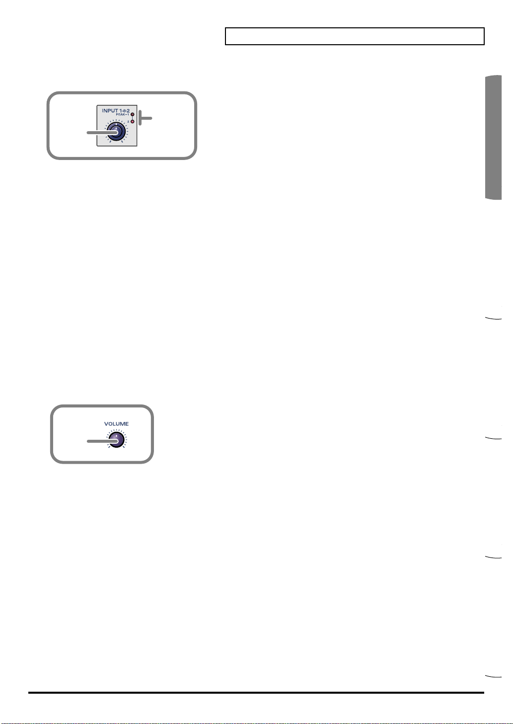
Español Italiano Français Deutsch English
■ Audio Control section
14
13
13. Input sensitivity knob
This dual concentric knob adjusts the input level to input jacks 1 and 2 (INPUT 1/L, INPUT 2/R).
The UR-80 provides XLR type and phone type input jacks, and you can use either type as
appropriate for the equipment you want to connect. However, please be aware that the input
sensitivity of these jacks will differ.
The inner knob adjusts the INPUT 1/L input level, and the outer (ring) knob adjusts the
INPUT 2/R level.
Input levels
XLR type: -50– -10 dBu
Phone type: -35– +4 dBu
If you are connecting a low output level device such as a mic, we recommend that you use the XLR
type input jack.
Names of Things and What They Do
14. Peak indicators (PEAK)
These indicators show whether the sound being input to input jacks 1 and 2 (INPUT 1/L,
INPUT-2/R) is distorting. Adjust the input sensitivity knob so that the peak indicators do not light.
The peak indicators will light red at a level -6 dB below clipping.
15
15. Output volume (VOLUME) knob
This adjusts the volume that is output from the headphone jack and the master output jacks.
* This does not affect the volume that is output from the digital output jacks.
23
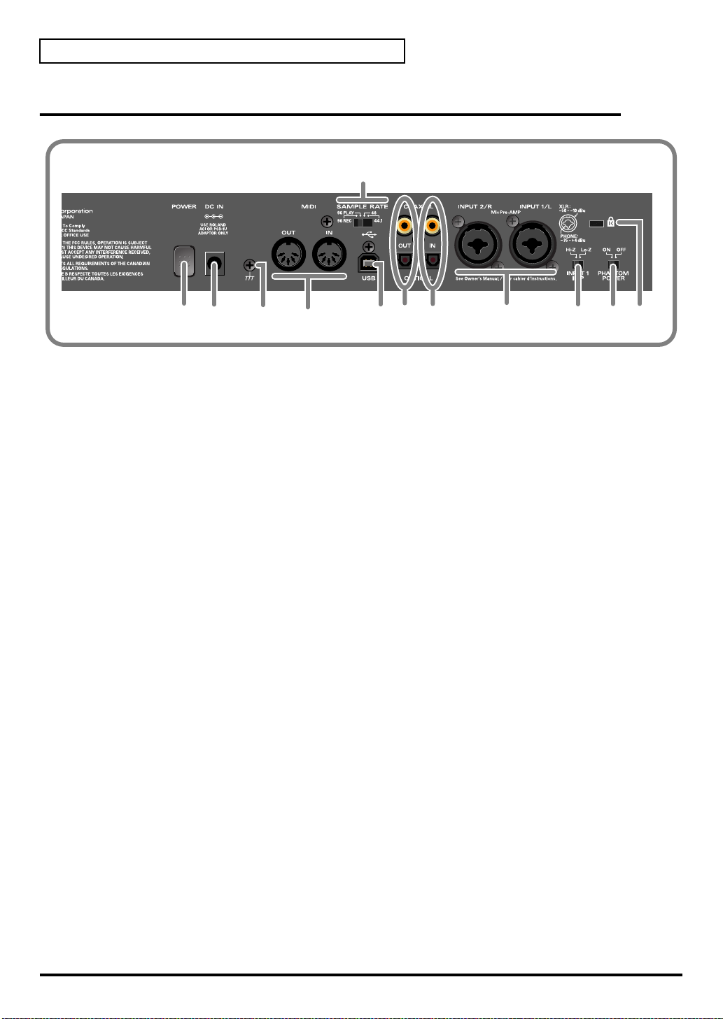
Names of Things and What They Do
Rear panel
fig.rear
20
16
17 18 19
16. Power switch (POWER)
Press this switch to turn the power on/off. The power is on when the switch is pressed inward.
17. AC adaptor connector (DC IN)
Connect the included AC adaptor here
18. Grounding terminal
Depending on the circumstances of a particular setup, you may experience a discomforting
sensation, or perceive that the surface feels gritty to the touch when you touch this device,
microphones connected to it, or the metal portions of other objects, such as guitars. This is due to
an infinitesimal electrical charge, which is absolutely harmless. However, if you are concerned
about this, connect the ground terminal (see figure) with an external ground. When the unit is
grounded, a slight hum may occur, depending on the particulars of your installation. If you are
unsure of the connection method, contact the nearest Roland Service Center, or an authorized
Roland distributor, as listed on the “Information” page.
21 22
23
24
Do not connect the grounding terminal to the following locations:
• Water pipe (this can cause electric shock)
• Gas pipe (this can cause explosion or fire)
• Telephone ground or lightning rod (hazardous during electrical storms)
19. MIDI IN/OUT connectors
25 26
27
Connect these connectors to the MIDI connectors of other MIDI devices to transmit and receive
MIDI messages.
20. Sampling frequency select switch (SAMPLE RATE)
This switch selects the sampling frequency at which the audio signal will be recorded and played
back.
* If you change the setting of this switch, you must then close all applications and turn the power of the
UR-80 off, then on again.
* If you are using the 96 kHz sample rate, you cannot record and play back simultaneously. You must select
either recording (96 REC) or playback (96 PLAY).
21. USB connector
Use a USB cable to connect this to your computer.
24
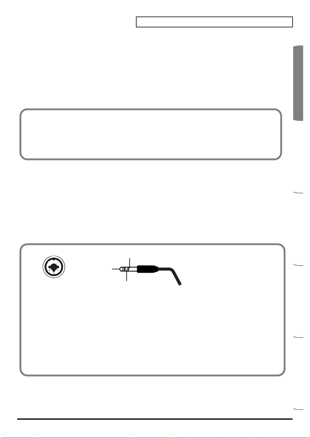
Español Italiano Français Deutsch English
Names of Things and What They Do
22. Digital output jacks
Use these jacks to output digital audio to a digital audio device such as a CD/MD/DAT.
23. Digital input jacks
Use these jacks to input digital audio from a digital audio device such as a CD/MD/DAT or from
a MIDI sound module that has a digital output jack.
* If you have connected a digital device to the optical (OPTICAL) connector, the optical connector will take
priority; the signals from the coaxial jacks will not be input.
You must use the appropriate type of cable for the digital output jack or digital input jack you are
using.
COAXIAL............ Coaxial cable
OPTICAL ............ Optical cable
* The UR-80’s digital input/output format complies with the S/P DIF standard.
24. Input jacks 1, 2 (INPUT 1/L, 2/R)
These are analog audio input jacks. You can connect either XLR type or phone type plugs. Balanced
and unbalanced connections are supported for either type. 48 V phantom power can be supplied
to XLR type connections, allowing you to use phantom-powered condenser mics. In this case, turn
the phantom power switch ON.
The XLR type and phone type jacks have different input sensitivity, as shown below.
XLR type.......-50– -10 dBu Phone type.........-35– +4 dBu
If you are connecting a device with a low output level, such as a mic, we recommend that you use
the XLR type input jack.
fig.XLRTRS
GND(SLEEVE)
1:GND
2:HOT
3:COLD
HOT(TIP)
COLD(RING)
* The UR-80 provides balanced (XLR/TRS) type input jacks, which are wired as shown in the diagram. Please
make sure that the device you are connecting is wired appropriately.
* The phantom power must be turned off unless you have connected a condenser mic that requires phantom
power. Malfunctions can occur if you supply phantom power to a dynamic mic or audio playback device. For
details on the specifications of your mic, refer to its owner’s manual. (The UR-80’s phantom power supply
provides a maximum of 10 mA at DC 48 V.)
* Do not connect different types of mic simultaneously; for example, do not connect a phantom-powered
condenser mic to input jack 1 and a dynamic mic to input jack 2. Supplying phantom power to a dynamic
mic or audio playback device will cause malfunctions.
25. Input impedance select switch (INPUT 1 IMP)
You can select either high impedance (Hi-Z) or low impedance (Lo-Z) for the device connected to
input jack 1. If you connect a guitar to input jack 1, set this to high impedance (Hi-Z).
25
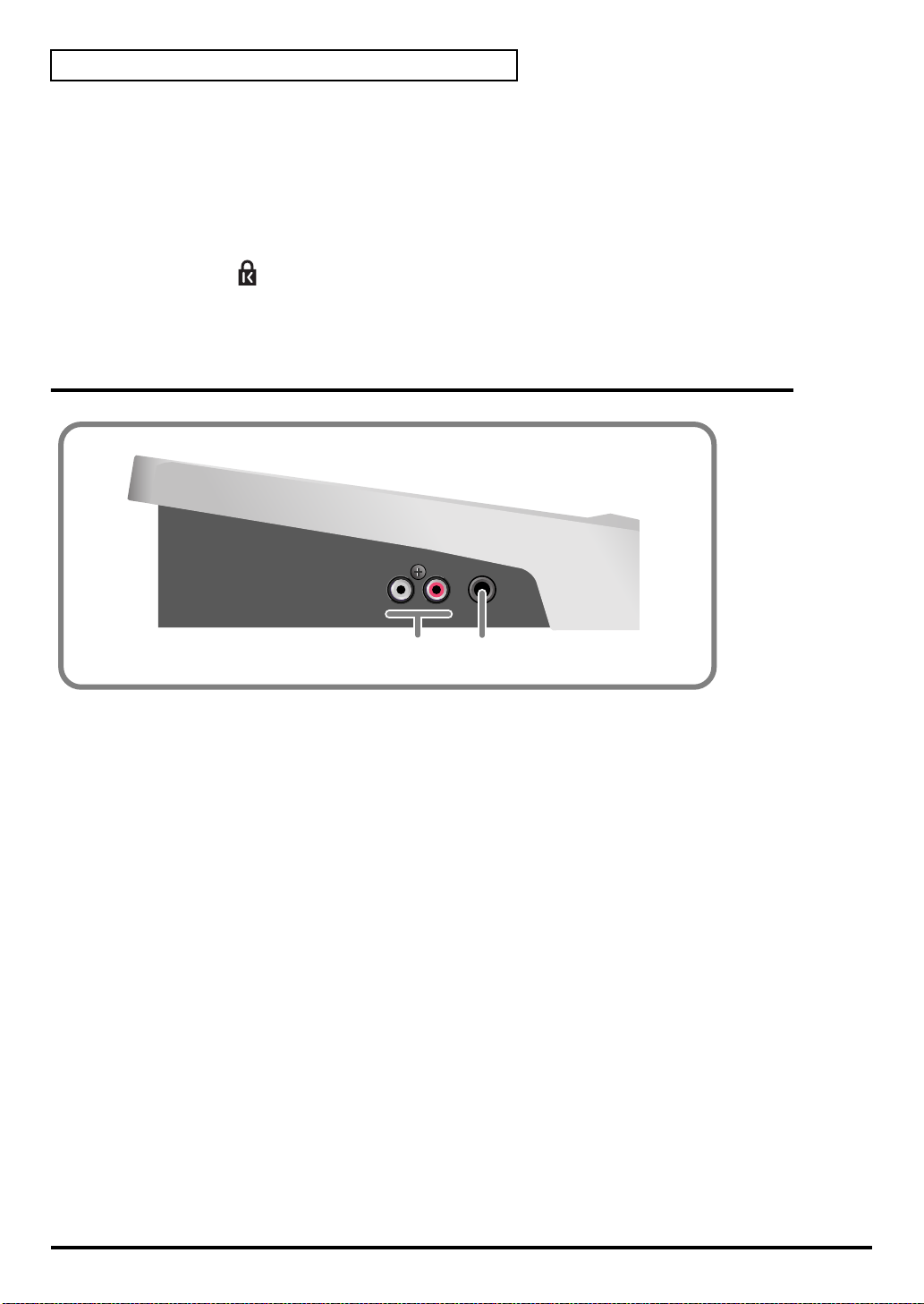
Names of Things and What They Do
26. Phantom power switch (PHANTOM POWER)
This is an on/off switch for the phantom power that is supplied to the XLR type input jacks 1 and 2.
* The phantom power must be turned off unless you have connected a condenser mic that requires phantom
power. Malfunctions can occur if you supply phantom power to a dynamic mic or audio playback device. For
details on the specifications of your mic, refer to its owner’s manual. (The UR-80’s phantom power supply
provides a maximum of 10 mA at DC 48 V.)
27. Security slot ( )
* http://www.kensington.com/
Side panel
fig.side
28 29
28. Master output jacks (RCA phono type)
These are analog audio output jacks. You can connect them to your external monitor speaker
system.
29. Headphone jack
You can connect a set of headphones to this jack. The headphone jack will output the same signal
as the master output jacks and digital output jacks. Sound will be output from the master output
jacks even if headphones are connected.
* Use the output volume knob of the Audio Control section to adjust the volume of the headphone jack and
master output jacks. It is not possible to adjust the volume that is output from the digital output jacks.
26

Español Italiano Français Deutsch English
Basic operation
27
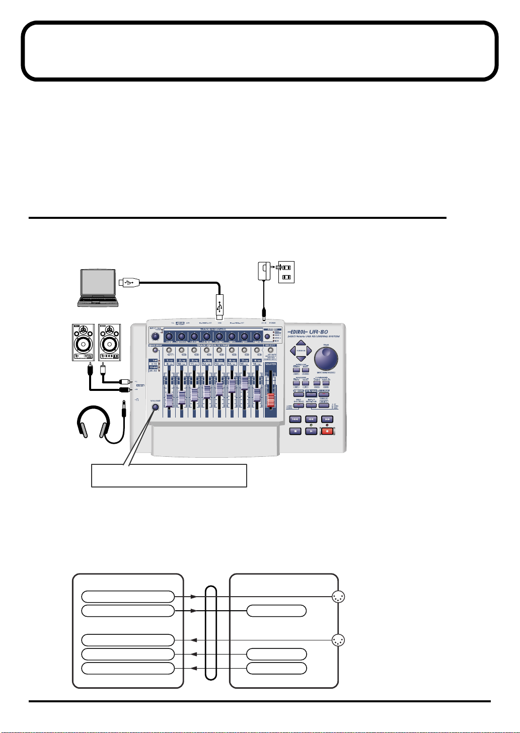
Basic connections and settings
This section explains basic connections and data routes for the UR-80.
* Before you make connections with other devices, you must turn down the volume of all devices to prevent
malfunctions or speaker damage.
If you connect your headphones or monitor speakers as shown in the diagram, you will be able
to monitor the playback from your software or the sound from instruments or audio devices
connected to the UR-80.
Basic connections
Simply use a USB cable to connect the UR-80 to your computer.
Connecting the USB cable allows both MIDI data and audio data to be transferred.
fig.basic.e
Computer
USB cable
AC adaptor
Monitor speakers
Headphones
This adjusts the volume that is output from
the headphone jack and the Monitor speakers.
USB
DC IN
■ MIDI flow
If the UR-80 and your computer are connected via USB cable
The MIDI data flow will be as shown below.
fig.flow-USB.e_80
UR-80PC (port name)
MIDI OUT device
EDIROL UR-80 MIDI OUT
EDIROL UR-80
MIDI IN device
EDIROL UR-80 MIDI IN
EDIROL UR-80 1
EDIROL UR-80 2
USB
Receive port
Transmit port 1
Transmit port 2
MIDI OUT
MIDI IN
28
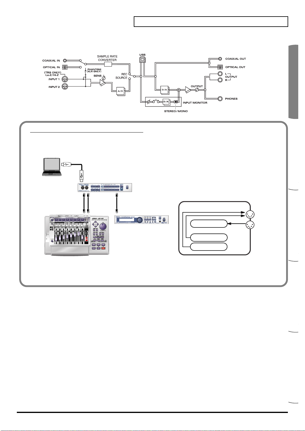
Español Italiano Français Deutsch English
■ Audio flow (block diagram)
fig.block
If you are using MIDI connections
Even if the UR-80 is not connected to your computer via a USB cable, you can connect the UR-80’s
MIDI IN/OUT connectors to a MIDI interface that is connected to your computer.
fig.connect-midi.e_80fig.flow-MIDI.e_8
USB cable
USB
Computer
MIDI interface (sold separately)
Basic connections and settings
MIDI IN
MIDI cables MIDI cable
MIDI OUT
MIDI OUT
MIDI IN
MIDI OUT
MIDI IN
MIDI sound module (sold separately)
UR-80
UR-80
MIDI OUT
Receive port
MIDI IN
Transmit port 2
Transmit port 2
* When connected via MIDI, the audio functionality
of the UR-80 will be unavailable.
29
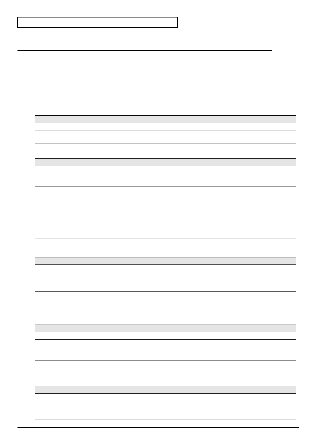
Basic connections and settings
Input/output devices
In order to obtain the best performance from your software, you must make the appropriate input/
output device settings.
For details on these settings, refer to the owner’s manual for your software.
* If you are unable to select the UR-80 in the device settings for your software, it is possible that the UR-80
driver was not installed correctly. Please reinstall the driver.
MIDI devices
MIDI OUT device
UR-80 MIDI OUT (Mac OS 9: UR-80 MIDI IN, OUT)
If you specify UR-80 MIDI OUT as the output port for your sequencer software, messages will
be transmitted from the MIDI OUT connector of the UR-80 itself.
UR-80 (Mac OS 9/8: UR-80 1)
Select this port if you want to send messages from your sequencer software to the UR-80 itself.
MIDI IN device
UR-80 MIDI IN (Mac OS 9: UR-80 MIDI IN, OUT)
If you specify UR-80 MIDI IN as the input port for your sequencer software, messages will be
input from the UR-80’s MIDI IN connector.
UR-80 1
UR-80 2
Select one of these ports if you want messages from the controllers to be received by your sequencer software. For each controller you can select the port that will be used. You may find it
convenient (for example) to use UR-80 1 for messages to be recorded on a track or used to control
a software synthesizer, and UR-80 2 for messages used to play back/stop your sequencer or
perform mixing.
Use UR-80 2 as the MIDI input device for UR-80 Editor.
Audio devices
Audio output device
EDIROL UR-80
MME EDIROL UR-80 Out
Audio input devices
EDIROL UR-80
MME EDIROL UR-80 In
ASIO device
This sends audio signals from your computer to the UR-80. If you are using Media Player you
will normally choose this. You should also use this if you are using an application such as SONAR in WDM driver mode or a DirectSound application.
This sends audio signals from your computer to the UR-80. Use this if you are using an application that does not have a WDM driver mode, or if you want to use 24-bit audio with a non-ASIO
application (such as Cool Edit).
* Windows XP/2000 only
This receives audio signals sent from the UR-80 to your computer. Normally, you should use
this. You should also use this when using an application such as SONAR in WDM driver mode.
This receives audio signals sent from the UR-80 to your computer. Use this if you are using an
application that does not have a WDM driver mode, or if you want to use 24-bit audio with a
non-ASIO application (such as Cool Edit).
* Windows XP/2000 only
Select “EDIROL UR-80” as the ASIO setting for your application if you are using the UR-80 with
an ASIO application such as Cubase.
* To prevent audio loops from causing oscillation or double monitoring, turn monitoring off in
your application or use the ASIO Direct Monitor setting.
30
 Loading...