

Page 1

Reference Manual
Copyright © 2016 ROLAND CORPORATION
Page 2

Contents
Getting Ready 4
Overview of the TD-50 . . . . . . . . . . . . . . . . . . . . . . . . . . . . . . . . . . . . 4
Drum Kits. . . . . . . . . . . . . . . . . . . . . . . . . . . . . . . . . . . . . . . . . . . . . . . 4
About Memory . . . . . . . . . . . . . . . . . . . . . . . . . . . . . . . . . . . . . . . . . . 5
About Performance Techniques . . . . . . . . . . . . . . . . . . . . . . . . . . . 6
Panel Descriptions . . . . . . . . . . . . . . . . . . . . . . . . . . . . . . . . . . . . . . . . 7
Turning the Power On/O . . . . . . . . . . . . . . . . . . . . . . . . . . . . . . . . 10
Making the Power Automatically Turn o After a Time
(AUTO OFF) . . . . . . . . . . . . . . . . . . . . . . . . . . . . . . . . . . . . . . . . . . . . 10
Making Hi-hat Settings . . . . . . . . . . . . . . . . . . . . . . . . . . . . . . . . . . . 11
Basic Operation . . . . . . . . . . . . . . . . . . . . . . . . . . . . . . . . . . . . . . . . . . . 12
Performing 13
Selecting a Drum Kit . . . . . . . . . . . . . . . . . . . . . . . . . . . . . . . . . . . . . . 13
Selecting a Drum Kit from the List . . . . . . . . . . . . . . . . . . . . . . . . . 13
Cross-Stick Function . . . . . . . . . . . . . . . . . . . . . . . . . . . . . . . . . . . . . 13
Stopping All Currently Played Sounds (ALL SOUND OFF) . . . . . 13
Playing with the Click . . . . . . . . . . . . . . . . . . . . . . . . . . . . . . . . . . . . . 13
Performing Along with a Song . . . . . . . . . . . . . . . . . . . . . . . . . . . . 14
Performing Along with an Audio Player Song . . . . . . . . . . . . . . . 14
Performing Along with a TD-50 Song . . . . . . . . . . . . . . . . . . . . . . 14
Repeatedly Playing a Specied Region (A-B Repeat) . . . . . . . . . 14
Changing the Settings of Each Song . . . . . . . . . . . . . . . . . . . . . . . 15
Playing an Audio File as a Click (Click Track) . . . . . . . . . . . . . . . . . 15
Rhythm Training (QUIET COUNT) . . . . . . . . . . . . . . . . . . . . . . . . . 16
Registering/Recalling Favorite Drum Kits (FAVORITE) . . . . . 16
Recording 17
Recording a Performance . . . . . . . . . . . . . . . . . . . . . . . . . . . . . . . . . 17
Recording Your Drum Performance . . . . . . . . . . . . . . . . . . . . . . . . 17
Recording Your Performance Along with a Song . . . . . . . . . . . . . 17
Deleting Recorded Data . . . . . . . . . . . . . . . . . . . . . . . . . . . . . . . . . . 17
Renaming Recorded Data . . . . . . . . . . . . . . . . . . . . . . . . . . . . . . . . 18
Exporting Recorded Data to an SD Card (SONG EXPORT) . . . . . 18
Customizing a Kit 19
Editing an Instrument (INSTRUMENT) . . . . . . . . . . . . . . . . . . . . 19
Selecting an Instrument . . . . . . . . . . . . . . . . . . . . . . . . . . . . . . . . . . 19
Choosing a Pad to Edit . . . . . . . . . . . . . . . . . . . . . . . . . . . . . . . . . . . 20
Auditioning the Sound of a Pad ([PREVIEW] button) . . . . . . . . . 20
Adjusting the Mic Settings (MIC POSITION) . . . . . . . . . . . . . . . . . 20
Adjusting the Attack and Release (TRANSIENT) . . . . . . . . . . . . . . 20
Layering Instruments (SUB INSTRUMENT) . . . . . . . . . . . . . . . . . . 21
Simulating the Ambience of a Performance Space
(AMBIENCE)
. . . . . . . . . . . . . . . . . . . . . . . . . . . . . . . . . . . . . . . . . . . . . . . 22
Editing the Mixer (MIXER). . . . . . . . . . . . . . . . . . . . . . . . . . . . . . . . . 22
Specifying the Volume and Pan of Each Pad . . . . . . . . . . . . . . . . . 22
Applying Eects . . . . . . . . . . . . . . . . . . . . . . . . . . . . . . . . . . . . . . . . . 23
Adjusting the Overall Sound
(MASTER COMPRESSOR/MASTER EQ). . . . . . . . . . . . . . . . . . . . . . . 23
Comparing with or Reverting to the Unedited Drum Kit
(SNAPSHOT) . . . . . . . . . . . . . . . . . . . . . . . . . . . . . . . . . . . . . . . . . . . . . . 24
Editing a Drum Kit (MENU) . . . . . . . . . . . . . . . . . . . . . . . . . . . . . . . . 24
Setting the Volume . . . . . . . . . . . . . . . . . . . . . . . . . . . . . . . . . . . . . . 24
Specifying the Illumination Color of the [KIT] Button and
Knobs . . . . . . . . . . . . . . . . . . . . . . . . . . . . . . . . . . . . . . . . . . . . . . . . . . 25
Renaming the Drum Kit . . . . . . . . . . . . . . . . . . . . . . . . . . . . . . . . . . 25
Performing with Brushes . . . . . . . . . . . . . . . . . . . . . . . . . . . . . . . . . 25
Specifying the Tempo for Each Kit . . . . . . . . . . . . . . . . . . . . . . . . . 26
Controlling Tonal Change . . . . . . . . . . . . . . . . . . . . . . . . . . . . . . . . . 26
Making MIDI Transmit/Receive Settings for Each Pad . . . . . . . . . 27
Importing and Playing Audio Files (USER SAMPLE) . . . . . . . 27
Importing an Audio File (IMPORT) . . . . . . . . . . . . . . . . . . . . . . . . . 27
Assigning a User Sample to an Instrument and Playing It . . . . . 28
Listing the User Samples . . . . . . . . . . . . . . . . . . . . . . . . . . . . . . . . . 28
Specifying How the User Sample Is Sounded . . . . . . . . . . . . . . . . 28
Specifying the Sounded Region of a User Sample . . . . . . . . . . . . 29
Deleting a User Sample . . . . . . . . . . . . . . . . . . . . . . . . . . . . . . . . . . 29
Renaming a User Sample . . . . . . . . . . . . . . . . . . . . . . . . . . . . . . . . . 29
Organizing User Samples . . . . . . . . . . . . . . . . . . . . . . . . . . . . . . . . . 29
Utility Functions 30
Using the TD-50 with a Computer . . . . . . . . . . . . . . . . . . . . . . . . 30
USB Driver Installation and Settings . . . . . . . . . . . . . . . . . . . . . . . . 30
Specifying the Output for USB Audio . . . . . . . . . . . . . . . . . . . . . . . 30
Specifying the Input for USB Audio . . . . . . . . . . . . . . . . . . . . . . . . 31
Copying Settings (COPY) . . . . . . . . . . . . . . . . . . . . . . . . . . . . . . . . . 31
Recalling Drum Kits Successively (SET LIST) . . . . . . . . . . . . . . 33
Creating a Set List . . . . . . . . . . . . . . . . . . . . . . . . . . . . . . . . . . . . . . . 33
Using Set Lists . . . . . . . . . . . . . . . . . . . . . . . . . . . . . . . . . . . . . . . . . . 34
2
Page 3

Settings 35
Trigger Settings (TRIGGER) . . . . . . . . . . . . . . . . . . . . . . . . . . . . . . . 35
Specifying the Pad Type . . . . . . . . . . . . . . . . . . . . . . . . . . . . . . . . . . 35
Specifying a Digitally-Connected Pad . . . . . . . . . . . . . . . . . . . . . . 35
Adjusting the Pad Sensitivity . . . . . . . . . . . . . . . . . . . . . . . . . . . . . . 36
Adjusting the Hi-Hat Settings . . . . . . . . . . . . . . . . . . . . . . . . . . . . . 36
Making Detailed Adjustments for the Trigger . . . . . . . . . . . . . . . 36
Making Detailed Settings for Digitally-Connected Pads . . . . . . . 37
Viewing Trigger Information for Each Pad . . . . . . . . . . . . . . . . . . . 37
Eliminate Crosstalk Between Pads (Crosstalk Cancellation) . . . . 38
Backing Up Data to an SD Card (SD CARD) . . . . . . . . . . . . . . . . 39
Backing Up All Settings (SAVE) . . . . . . . . . . . . . . . . . . . . . . . . . . . . 39
Loading Backup Data from an SD Card (LOAD) . . . . . . . . . . . . . . 39
Backing Up Drum Kit to an SD Card (1 KIT SAVE) . . . . . . . . . . . . . 40
Loading Kit Backup Data from an SD Card (1 KIT LOAD) . . . . . . . 40
Deleting Backup Data from an SD Card (DELETE/1 KIT DELETE) 41
Checking the Usage Status of an SD Card (INFO) . . . . . . . . . . . . . 41
Formatting an SD Card (FORMAT ). . . . . . . . . . . . . . . . . . . . . . . . . . 41
Settings for the Entire TD-50 (SETUP) . . . . . . . . . . . . . . . . . . . . . 42
Audio Output Assignments (OUTPUT) . . . . . . . . . . . . . . . . . . . . . . 42
Other Settings (OPTION). . . . . . . . . . . . . . . . . . . . . . . . . . . . . . . . . . 44
Assigning Functions to Foot Switches or Pads (CONTROL) . . . . 45
MIDI Settings (MIDI) . . . . . . . . . . . . . . . . . . . . . . . . . . . . . . . . . . . . . 45
Viewing Information for the TD-50 Itself (INFO) . . . . . . . . . . . . . . 46
Restoring the Factory Settings (FACTORY RESET) . . . . . . . . . . . . 46
Contents
Appendix 47
List of Displayed Messages . . . . . . . . . . . . . . . . . . . . . . . . . . . . . . . 47
Error Messages . . . . . . . . . . . . . . . . . . . . . . . . . . . . . . . . . . . . . . . . . . 47
Other Messages . . . . . . . . . . . . . . . . . . . . . . . . . . . . . . . . . . . . . . . . . 47
Troubleshooting . . . . . . . . . . . . . . . . . . . . . . . . . . . . . . . . . . . . . . . . . . 48
Main Specications . . . . . . . . . . . . . . . . . . . . . . . . . . . . . . . . . . . . . . . 49
3
Page 4

Getting Ready
Overview of the TD-50
Drum Kits
On the TD-50, the sound you hear when you strike each pad is called an “instrument.” A “drum kit” is a set of sounds (instruments) assigned to the
pads.
Drum kit 100
Drum kit 1
Pads
KICK
Head
TOM 4
Head
Rim
AUX 1
Head
Rim
Ambience settings
Location of performance, wall materials, depth, etc.
Overall settings for the entire drum kit
Overall volume of the drum kit, drum kit name, MIDI
settings, etc.
SNARE
Head
Rim
HI-HAT
Head
Rim
AUX 2
Head
Rim
MEMO
5 When you change a drum kit setting, the changed setting is saved automatically.
5 For details on a drum kit’s parameter structure, refer to “Data List” (PDF).
TOM 1
Head
Rim
CRASH 1
Head
Rim
AUX 3
Head
Rim
TOM 2
Head
Rim
CRASH 2
Head
Rim
AUX 4
Head
Rim
TOM 3
Head
Rim
RIDE
Head
Rim
Bell
Mixer settings
Multi-eect, master compressor, master equalizer, etc.
Pad settings
Pad compressor, etc.
Settings for all instruments (head)
Volume, pan, pad equalizer, how sub-instruments are
sounded, etc.
Instrument
Instrumental sound, mic settings, transient, etc.
Sub-instrument
Instrumental sound, mic settings, transient, etc.
Settings for all instruments (rim)
Instrument (p. 19)
An instrumental sound such as a snare drum or kick drum is called an
“instrument.”
An instrument is assigned to each location of a pad that can be
struck independently, such as the pad’s head and rim.
You can also change the settings of each instrument to create your
own sound. An instrument can reproduce the timbral changes
caused by the depth of a drum shell, and lets you apply mic settings
or transient eects.
An audio le that you create on your computer can also be loaded
from an SD card into the TD-50 and played as an instrument (the user
sample function).
Ambience (p. 22)
“Ambience” is an eect that simulates the acoustical character of the
location in which you’re performing.
You can adjust the room ambience (the type and size of the room),
the reverb (reverberation), and the stereo enhancer (the sense of
stereo spaciousness).
The ambience eect can be applied individually to each drum kit.
You can also specify how strongly the eect applies to each pad.
4
Mixer (p. 22)
These settings adjust the volume balance, pan, and eects for each
pad.
The TD-50’s eects include the types shown below. Some eect
types apply to individual pads, and some apply to the entire drum
kit.
Eect Explanation
An “equalizer” lets you adjust specic separate
frequency ranges such as high, mid, and low.
Pad equalizer/
Pad compressor
(PAD COMP/PAD EQ)
Multi-eects (MFX)
Master compressor/Master
EQ (MASTER COMP/MASTER
EQ)
A “compressor” is an eect that reduces volume
peaks, by modifying the attack and release of
the sound.
The pad equalizer can apply an eect to
each separate strike location, and the pad
compressor can apply an eect to each
individual pad.
“Multi-eects” let you apply three eects that
you choose from 30 types.
Multi-eects can apply an eect to each
individual drum kit. You can also specify how
much eect is applied to each pad.
Compressor and equalizer can be applied to
the entire drum kit.
Page 5

About Memory
The area in which settings such as drum kits and trigger settings are stored is called “memory.”
Getting Ready
TD-50
Preset memory
Drum kits
Set lists
Trigger settings
User samples (presets)
COPY
User memory
Drum kits
Set lists
Trigger settings
Setup
User samples
Temporary memory
(saved temporarily)
Recorded data
COPY
LOAD
SAVE
SD card
Backup
Drum kit
User samples
Recorded data
Preset memory
The factory settings are stored in preset memory.
You can restore the factory settings by copying preset memory data to user memory (p. 46).
The following settings are saved in preset memory.
5 Drum kits (p. 4)
5 Set lists (p. 33)
5 Trigger settings (p. 35)
5 User samples (presets) (p. 27)
* User samples (presets) cannot be copied. By executing a factory reset, you can return the user samples in user memory to their factory-set state.
User memory
This area stores your edits and performance settings.
Data from SD card or preset memory can also be loaded or copied into this area (p. 31).
The following settings are saved in user memory.
5 Drum kits (p. 4)
5 Set lists (p. 33)
5 Trigger settings (p. 35)
5 Setup (p. 42)
5 User samples (p. 27)
Temporary memory (saved temporarily)
The data (one song) recorded on the TD-50 is held in the unit’s temporary memory.
The recorded data in temporary memory can be copied to an SD card, or exported as an audio le (WAV) or SMF data to an SD card.
* When you turn o the power, the data recorded in temporary memory is erased.
SD card
The settings saved in user memory can be saved as a set on an SD card, allowing you to save (back up) up to 99 sets.
Separately from backups, 999 drum kits can also be saved.
Your performance on the TD-50 can also be recorded directly to an SD card.
MEMO
5 The data that is saved on an SD card can be loaded into user memory, or copied. For details, refer to “Backing Up Data to an SD Card (SD CARD)”
(p. 39).
5 For details on the folder structure of an SD card, refer to “SD card folder structure” (p. 40).
5
Page 6

Getting Ready
About Performance Techniques
The TD-50 responds to a variety of performance techniques just like
an acoustic drum set.
NOTE
5 Use only wooden or plastic sticks. Using a carbon or metal
stick may cause the sensor to malfunction.
5 Use nylon brushes. Using metal brushes may cause the
sensor to malfunction, and may scratch the pad.
Pad
Playing method Explanation
Head shot
Hit only the head of the pad.
For a snare drum, the tone will change naturally as you
move the strike location from the center of the head
Tone changes depending
on strike point
Rim shot
Cross stick
Playing with brushes
Change the nuance of the rim shot
With certain snare and tom sounds, slight changes in the way you
play rim shots changes the nuance.
Playing method Explanation
Normal rim shot
(Open rim shot)
Shallow rim shot
toward the rim.
Strike the head and the rim of the pad simultaneously.
A sound (rim sound) dierent than the head shot will
be heard.
Strike the rim while placing your hand on the head.
Snare sounds can produce dierent sounds in response
to dierent playing techniques; for example they can
produce a rim sound when played using a rim shot,
or a cross-stick sound when played using a cross-stick
technique.
Either connect a pad that supports rim shot playing
technique to the TRIGGER IN (2 SNARE) jack, or connect
a pad that supports cross-stick technique and allows a
digital connection (such as the PD-140DS) and assign it
to the snare.
* On units other than the PD-140DS, strike only the rim
so as not to touch the head.
* On some snare sounds, it might not be possible to
play separate sounds in this way.
You can use brushes to scrape the head (brush sweep).
Connect a mesh head pad to the TRIGGER IN (2 SNARE)
jack or connect a digitally-connected pad that allows
brush playing (such as the PD-140DS), assign it to snare,
and assign an instrument that supports brush playing to
the head of the snare.
* This is supported starting with program version 1.05.
Refer to the Roland website for the latest information.
http://www.roland.com/support/
Strike the head and rim simultaneously.
Simultaneously strike the head near the rim and the
rim itself.
Hi-Hat
Playing method Explanation
Open/closed
Pressure (VH-13)
The hi-hat tone changes smoothly and continuously
from open to closed in response to how far the pedal
is pressed.
You can also play the foot closed sound (playing the
hi-hat with the pedal completely pressed down) and
foot splash sound (playing the hi-hat with the pedal
fully pressed and then instantly opening it).
When you strike the hi-hat while pressing on the
pedal with the hi-hat closed, you can then change the
closed tone in response to the pressure you place on
the pedal.
* The VH-11, FD-9, and FD-8 do not respond to
pressure.
Bow shot
This playing method involves striking the middle area
of the top hi-hat. It corresponds to the sound of the
“head-side” of the connected trigger input.
Edge shot
Edge sensor
* Do not strike the bottom of the top hi-hat, and do not strike the
bottom hi-hat. Doing so will cause malfunctions.
This playing method involves striking the edge of the
top hi-hat with the shoulder of the stick. When played
as shown in the gure, the “rim-side” sound of the
connected trigger input is triggered.
* Striking directly on the edge (i.e., exactly from the
side) will not produce the correct sound. Strike as
shown in the illustration.
Cymbal
Playing method Explanation
Bow shot
Edge shot
Edge sensor
Bell shot
Choke play
Edge sensor
Nuance changes
depending on the
strike location
Sensor
This is the most common playing method,
playing the middle area of the cymbal. It
corresponds to the sound of the “head-side” of
the connected trigger input.
This playing method involves striking the edge
with the shoulder of the stick. When played as
shown in the gure, the “rim-side” sound of the
connected input is triggered.
This is the technique of striking the bell. When
the bell area shown in the illustration is struck,
the bell sound is heard.
Connect a compatible pad to the TRIGGER IN
(10 RIDE - BELL) jack, or connect a pad that
allows the bell shot technique and supports a
digital connection (such as the CY-18DR), and
assign it to ride.
If you use your hand to choke (grasp) the edge
sensor after striking the cymbal, the sound
stops.
On the CY-18DR, placing your hand on the
sensor will also stop the sound.
When you strike the cymbal in the choked state,
the sound is shorter.
The choke technique can also be used on the
hi-hat.
6
Page 7

Panel Descriptions
Top Panel
Getting Ready
1
2
3
7
9
8
4
5
6
No. Controller Explanation Page
[MASTER] knob Adjusts the volume of the MASTER OUT jacks. p. 12
1
[PHONES] knob Adjusts the volume of the headphones connected to the PHONES jacks. p. 12
TRIG SELECT
[LOCK] button
2
[RIM] button
SELECT [K] [J] buttons
[F1]–[F5] buttons
(function button)
(rotary knobs)
3
PAGE [UP] [DOWN] buttons By pressing the PAGE [UP] [DOWN] buttons when they are lit, you can switch pages in the screen.
TRIGGER ACTIVITY
indicator
Display This shows various information depending on the operation. –
[MIX IN] knob Adjusts the volume that is input to the front panel and rear panel MIX IN jacks. –
[SONG] knob
[SONG] button
4
[CLICK] knob Adjusts the volume of the click. p. 13
[CLICK] button Allows you to sound the click, or to make settings for the tempo or click. You’ll also press this for rhythm training.
[s] button
[t] button
Faders Adjust the volume of the kick, snare, hi-hat, other percussion instruments, and ambience. p. 12
5
[KIT] button Accesses the DRUM KIT screen. p. 13
[–] [+] buttons Use these buttons to switch drum kits or to edit values. p. 12
[EXIT] button
6
[ENTER] button Press this to conrm a value or execute an operation. p. 12
[SHIFT] button This button is used in conjunction with other buttons. The function of other buttons changes while this button is held down. –
[PREVIEW] button
[H] [I] [K] [J] buttons
(cursor buttons)
7
Dial This dial functions like the [+] and [–] buttons. Use it to scroll quickly or make large changes in edited values. p. 12
If you press the [LOCK] button so its indicator is lit, the pad for which settings are being made will remain selected even if you
strike a pad.
When using a pad that provides rim support, this button species whether you’re making settings for the head or the rim. In the
case of a pad that supports three-way triggering, this button switches between the head, rim, and bell.
Select the pad (trigger input number) for which to make settings.
These buttons change their function depending on the indication in the display. Use them to switch the tabs that are shown in
the upper part of the display, or to specify the function that is shown in the upper or lower part of the display.
The functions of these knobs changes depending on the indication in the display. They adjust the values that are shown in the
lower part of the display.
This lights when a trigger signal is received from a pad (a signal indicating that the pad is struck). This lets you check whether the
pad is connected correctly.
Adjusts the volume of the song (audio le) (This does not aect the sound of an internal song’s drum performance, nor the sound
of a recorded drum performance).
Accesses the SONG screen. Press this when you want to play back a song or recorded data, or when you want to make songrelated settings.
Plays/stops the song or the recorded data. p. 13
Press this when you want to record your performance. p. 17
Press this once to return to the next higher screen level. If you press it repeatedly, you’ll eventually return to the DRUM KIT screen.
By holding down the [SHIFT] button and pressing the [EXIT] button, you can stop (mute) all currently-playing sound (ALL SOUND
OFF (p. 13)). This is a convenient way to stop numerous loop phrases in a single operation.
This button auditions an instrument. The volume changes depending on how strongly you strike the button.
You can use the SELECT [K] [J] buttons to select a trigger input number, and use this button to audition the sound even if no
pads are not connected to the TD-50.
Move the cursor. p. 12
p. 20
p. 12[R1]–[R3] knobs
–
–
p. 14
p. 13
p. 16
p. 12
p. 20
7
Page 8

Getting Ready
No. Controller Explanation Page
KIT CUSTOMIZE
[INSTRUMENT] button
8
[AMBIENCE] button Allows you to specify the size and resonance of the room in which the drums are being played. p. 22
[MIXER] button Allows you to specify the volume, pan, multi-eect, equalizer, and compressor settings for each pad. p. 22
[SNAPSHOT] button
[SD CARD] button
[SETUP] button
9
[TRIGGER] button Allows you to make trigger parameter settings. p. 35
[SET LIST] button
Allows you to specify an instrument (sound).
By holding down the [SHIFT] button and pressing the [INSTRUMENT] button, you can move directly to the instrument edit
(V-EDIT) page.
Temporarily saves the currently-edited drum kit, allowing you to compare it with the current settings or return to previous
settings (snapshot function).
Allows you to perform SD card operations such as saving or loading data.
By holding down the [SHIFT] button and pressing the [SD CARD] button, you can copy the settings of a drum kit or instrument
(p. 31).
Allows you to make settings for functions that apply to the entire TD-50, such as output-destination settings (output assign) and
MIDI settings.
By holding down the [SHIFT] button and pressing the [SETUP] button, you can use the user sample function (p. 27) which allows
you to import user samples.
Allows you to create a set list, or to switch drum kits in the order specied by a set list. When the set list function is on, the [SET
LIST] button is lit.
p. 19
p. 24
p. 39
p. 42
p. 33
Side Panel/Front Pane
Computer
A
SD card
Audio player
B
C
Headphones
No. Jack Explanation Page
USB COMPUTER port
A
SD card slot
B
PHONES jacks
C
MIX IN jack Connect your audio player (smartphone) or other audio playback device here. –
Use a USB cable to connect the TD-50 to your computer.
You can use DAW software to record your TD-50 performance as audio or MIDI, and you can play back sound from your
computer through the TD-50.
Insert a commercially available SD card (SDHC cards (up to 32 GB) are supported).
You can store songs or TD-50 data on the SD card.
You can also use a card to load user samples or to export a recorded song.
Before using an SD card for the rst time, you must format it on the TD-50 (p. 41).
* Never turn o the power or remove the SD cards while the screen indicates “Processing...”
Connect your headphones here.
Even if headphones are connected, sound is output from the various output jacks.
p. 30
p. 17
p. 39
–
Bottom Panel
Mounting the TD-50 on the stand
You can attach the TD-50 to a drum stand by using the sound module mounting plate
included with the drum stand (sold separately: MDS series).
Using the screws on the bottom of the TD-50, attach it as shown in the illustration.
* Do not use any screws other than the screws from the bottom of the TD-50. Doing so will
cause malfunctions.
* When turning the unit over, be careful so as to protect the buttons and knobs from
damage. Also, handle the unit carefully; do not drop it.
MEMO
The All Purpose Clamp (APC-33; sold separately) can be attached to a pipe of 10.5–28.6
mm radius in case you want to mount the TD-50 on a cymbal stand or other such stand.
8
Wide
Narrow
Sound module
mounting plate
Page 9

Rear Panel (Connect Your Equipment)
Getting Ready
or other MIDI device
D E
MixerFootswitchExternal sound module
G
F
Sampling pad or
other electronic
musical instrument
H
I
K
J
(digital connection)
No. Jack Explanation
[L] switch
D
AC IN jack Connect the included AC power code to this inlet.
MIDI connectors Use these connectors to connect an external sound module or other MIDI device.
E
FOOT SW jack You can connect a footswitch (BOSS FS-5U, FS-6; sold separately) here and use it to control various things.
F
DIRECT OUT (BALANCED)
G
jacks
MIX IN (STEREO) jack Connect this to an electronic musical instrument such as a sampling pad.
H
MASTER OUT (BALANCED)
jacks
I
MASTER OUT
(UNBALANCED) jacks
TRIGGER IN jacks
J
DIGITAL TRIGGER IN ports Connect pads that support digital connection (e.g., PD-140DS or CY-18DR) here.
K
Press this switch to turn it on/o.
Connect these to your mixer.
Use the [SETUP] button to specify the DIRECT OUT 1–8 jack from which
each instrument is output.
Connect these to your mixer, amplied speakers, or recording device.
If you want to output in mono, connect only the L/MONO jack of the
MASTER OUT (UNBALANCED) jacks.
Connect cymbal, hi-hat, kick, and other pads here.
* If connecting a dual trigger type pad, use a stereo (TRS) cable.
PadsPads
* Pin assignment of the DIRECT
OUT (BALANCED) jacks
* Pin assignment of the MASTER
OUT (BALANCED) jacks
Mixer or amplied
speakers
Settings for pads that support digital connection
The rst time that a pad that supports digital connection is
connected to a DIGITAL TRIGGER IN port, the following screen
appears.
Following the instructions in the screen, make settings to specify
the trigger input to which the connected pad should be assigned.
* If you specify the same trigger input as a pad that is connected
to a TRIGGER IN jack, the pad that’s connected to that TRIGGER
IN jack won’t produce sound.
Reference
For details on pad settings, refer to “Specifying a DigitallyConnected Pad” (p. 35).
* To prevent malfunction and equipment failure, always turn down the volume, and turn o all the units before making any connections.
1. Select “OK” and press the [ENTER] button.
2. Use the cursor buttons to select the pad that you want
to specify, and use the [–] [+] buttons or the dial to
specify the assignment.
When you select a pad, the FUNC button of the selected pad
blinks.
(Setting example)
* You can’t specify multiple instances of the same assignment.
Pad Assign
PD140DS SNARE
CY18DR RIDE
3. Press the [KIT] button to return to the DRUM KIT screen.
9
Page 10

Getting Ready
Turning the Power On/O
* Once everything is properly connected (p. 9), be sure to follow
the procedure below to turn on their power. If you turn on
equipment in the wrong order, you risk causing malfunction or
equipment failure.
* Before turning the unit on/o, always be sure to turn the volume
down. Even with the volume turned down, you might hear some
sound when switching the unit on/o. However, this is normal
and does not indicate a malfunction.
Turning the power on
1. Minimize the volume of the TD-50 and the connected
devices.
2. Press the TD-50’s [
When you turn the TD-50 on, the following screen appears.
In this screen you can enable or disable the AUTO OFF function.
Button Explanation
[F1] (OFF) Button The power does not turn o automatically.
[F4] (4 HOURS)
Button
If the AUTO OFF function is set to “OFF,” this screen won’t appear.
MEMO
If a pad that supports digital connection is connected, the pad
setting screen might appear. For details, refer to “Settings for
pads that support digital connection” (p. 9).
3. Power-on the connected devices, and adjust the volume.
L
] switch.
When four hours have elapsed without any pad
being struck or any operation being performed, the
unit will turn o automatically.
Making the Power Automatically Turn o After
a Time (AUTO OFF)
The power to this unit will be turned o automatically after
a predetermined amount of time has passed since it was
last used for playing music, or its buttons or controls were
operated (AUTO OFF function).
If you do not want the power to be turned o automatically,
disengage the AUTO OFF function.
* To restore power, turn the power on again.
1. Press the [SETUP] button.
2. Use the PAGE [UP] [DOWN] buttons and the function
buttons to select “AUTO OFF.”
The AUTO OFF screen appears.
3. Use the [–] [+] buttons or the dial to specify the setting of
the auto-o function.
Value Explanation
OFF The power does not turn o automatically.
4 HOURS
4. Press the [KIT] button to return to the DRUM KIT screen.
MEMO
If the auto-o function is set to “4 HOURS,” the message
“WARNING: AUTO OFF, The TD-50 will turn o in 30 min.” will
appear 30 minutes before turning the TD-50 o.
When four hours have elapsed without any pad
being struck or any operation being performed, the
unit will turn o automatically.
Turning the power o
NOTE
Settings that you edit on the TD-50 are saved when you turn o
the unit. Be sure to turn o the unit by pressing the [L] switch.
1. Minimize the volume of the TD-50 and the connected
devices.
2. Turn o the power to the connected devices.
3. Press the TD-50’s [
The screen will indicate “Please wait. Now saving...,” and the unit will
turn o when the settings have been saved.
* If you need to turn o the power completely, rst turn o the
unit, then unplug the power cord from the power outlet. Refer
to “To completely turn o power to the unit, pull out the plug
from the outlet” (Quick Start).
L
] switch.
10
Page 11

Getting Ready
Making Hi-hat Settings
If you’re using the VH-13 or VH-11 V-hi-hat, adjust the oset on the
TD-50.
This adjustment is required for pedal movements such as open or
close to be detected correctly.
Settings for the VH-13
1. Press the [TRIGGER] button.
2. Press the PAGE [UP] button to access page 1 (TRIG BASIC).
3. Press the [F4] (HI-HAT) button.
The TRIGGER HI-HAT screen appears.
4. Use the [–] [+] buttons or the dial to set the Trig Type to
“VH13.”
5. Press the [F5] (OFFSET) button.
The VH OFFSET ADJUSTMENT screen appears.
Settings for the VH-11
1. After making the hi-hat settings, release your foot from
the pedal, and while keeping your foot o the pedal, turn
on the power of the TD-50.
2. Loosen the clutch screw and let the hi-hat rest naturally
on the motion sensor unit.
3. Press the [TRIGGER] button.
4. Press the PAGE [UP] button to access page 1 (TRIG BASIC).
5. Press the [F4] (HI-HAT) button.
6. Use the [–] [+] buttons or the dial to set the Trig Type to
“VH11.”
7. While reading the meter displayed on the right side of the
TD-50’s screen, adjust the oset with the VH-11’s VH oset
adjustment screw.
Adjust the oset so that the appear in the meter.
6. Loosen the clutch screw of the top hi-hat and let it sit on
the bottom hi-hat.
* Do NOT touch the hi-hats or the pedal.
7. Press the [F5] (EXECUTE) button.
The “VH Oset” parameter is set automatically (approx. 3 seconds).
The [TRIGGER] button stops ashing and remains lit.
8. Press the [KIT] button to return to the DRUM KIT screen.
Reference
If you need, make further adjustments to the parameters, refer
to “Data List (PDF).”
8. Press the [KIT] button to return to the DRUM KIT screen.
Reference
If you need, make further adjustments to the parameters, refer
to “Data List (PDF).”
11
Page 12

Getting Ready
Basic Operation
Switching tabs and specifying functions ([F1]–
[F5] buttons, [R1]–[R3] knobs)
You can use the [F1]–[F5] buttons to switch the tabs that are
shown at the top of the display, or specify the functions that
are shown at the top and bottom of the display.
You can also use the [R1]–[R3] knobs to change the values
that are shown at the bottom of the display.
Adjusting the overall volume
([MASTER] knob, [PHONES] knob)
Use the [MASTER] knob to adjust the
volume that is output from the MASTER
OUT jacks. Use the [PHONES] knob to
adjust the headphone volume.
Switching pages (PAGE [UP] [DOWN] buttons)
Use the PAGE [UP] [DOWN] buttons to switch pages in the
screen.
In screens where you can switch pages, the PAGE [UP] [DOWN]
buttons are lit, and in the right side of the display there is an
indication of which page you are in.
Adjusting the volume balance of each pad
(faders)
Use the faders to adjust the volume balance of the entire
TD-50.
By using the mixer (p. 22), you can adjust the volume balance
of the pads in each kit. Mixer settings can be saved for each
individual kit.
You can adjust the following trigger inputs and volumes.
Fader Explanation
KICK KICK
SNARE SNARE
TOMS TOM1–4
HI-HAT HI-HAT
CRASH CRASH1, 2
RIDE RIDE
AUX AUX1–4
AMBIENCE AMBIENCE
Returning to the previous screen ([EXIT] button)
When you want to return to the previous screen, press the
[EXIT] button.
Conrming an operation ([ENTER] button)
Press this button to nalize a value or conrm an operation.
Editing a value ([–] [+] buttons/dial)
To edit the value that’s highlighted by the cursor, use the
dial or the [–] [+] buttons.
If you operate these while holding down the [SHIFT]
button, the value changes more quickly.
MEMO
If you hold down the [+] button and press the [–]
button, the value will increase rapidly. If you hold
down the [–] button and press the [+] button, the
value will decrease rapidly.
Moving the cursor (cursor buttons)
Cursor refers to the highlighted characters indicating an
on screen parameter that can be set. When there is more
than one possibility within the screen, use the cursor
buttons to move it.
12
Page 13

Performing
Selecting a Drum Kit
1. Press the [KIT] button.
The DRUM KIT screen appears.
2. Use the [–] [+] buttons or dial to select a drum kit.
About the DRUM KIT screen
This is the TD-50’s main screen; it will appear when you press a
[DRUM KIT] button.
Tempo (shown only if the kit
tempo is “ON”)
Drum kit number
Drum kit name
Brush icon (shown only if Brush
Switch is “ON”)
Favorite icon (shown
only if a drum kit
that is registered as a
favorite is selected)
User sample icon (shown only
if a drum kit that uses user
samples (p. 27) is selected)
Stopping All Currently Played Sounds (ALL SOUND OFF)
Here’s how to stop the currently-playing drum performance sounds
and user samples (p. 27).
* The eect reverberation, the song, and the click do not stop.
1. If you want to stop the currently-playing performance
sounds, hold down the [SHIFT] button and press the
[EXIT] button.
Reference
You can also stop all currently-playing performance sounds by
using a pad or footswitch (p. 45).
Playing with the Click
Turning the click on/o
1. Press the [CLICK] button.
The CLICK screen appears.
Selecting a Drum Kit from the List
In the DRUM KIT screen, turn the [R1] (LIST) knob; KIT LIST appears,
allowing you to select a drum kit from the list.
Cross-Stick Function
When playing using a pad that’s connected to a TRIGGER IN
jack
Each time you press the [F4] (XSTICK) button, you’ll switch between
sounding and not sounding the cross-stick sound (p. 6) from the
snare pad.
2. Press the [F1] (TEMPO) button.
3. Press the [F5] button.
The click sounds.
You can adjust the volume of the click using the [CLICK] knob.
4. Press the [F5] button once again.
The click stops.
MEMO
You can also turn the click on/o by holding down the [SHIFT]
button and pressing the [CLICK] button.
Reference
You can also output the click only to headphones. For details,
refer to (p. 42).
Changing the tempo
1. In the CLICK screen (TEMPO tab), turn the [R1] knob to
adjust the tempo.
Reference
You can specify the tempo individually for each drum kit (p. 26).
Changing the beat unit
1. In the CLICK screen (TEMPO tab), turn the [R2] knob to
change the time signature.
When playing using a pad that supports digital connection
and cross-stick technique (such as the PD-140DS)
If you assign the trigger input to snare (p. 9), cross-stick technique
(p. 6) will always be available.
In this case, the XSTICK icon is not shown in the screen.
2. Press the [KIT] button to return to the DRUM KIT screen.
Reference
For other settings, refer to “Data List” (PDF).
13
Page 14

Performing
Performing Along with a Song
Performing Along with an Audio Player Song
Here’s how to connect an audio player (smartphone) to the MIX IN
jack, and perform along with a song.
1. Connect an audio player to the MIX IN jack (p. 8, p. 9).
2. Play back the audio player.
3. Turn the [MIX IN] knob to adjust the volume of the song.
Performing Along with a TD-50 Song
The TD-50 contains songs of a wide range of genres.
Some internal songs consist only of audio data, and others record a
drum performance (MIDI data).
An audio le (WAV or MP3) on an SD card can also be played back
as a song.
Here’s how to perform along with a song.
1. Press the [SONG] button.
The SONG screen appears.
Reference
5 By outputting an audio le from the SD card as a click track,
you can play a click along with the song (p. 15).
5 You can connect the TD-50 to your computer and play back
sound from your computer. For details, refer to “Specifying
the Input for USB Audio” (p. 31).
When transferring les from your computer to
an SD card
Audio les can be played back not only from the top level of
the SD card drive, but also from within a folder.
* You can put up to 200 song les in a single folder.
* Keep the length of the song to less than one hour per le.
Reference
For details, refer to “SD card folder structure” (p. 40).
Audio les that can be played by the TD-50
WAV MP3
Format (extension) WAV (.wav) MP3 (.mp3)
Sampling frequency 44.1 kHz 44.1 kHz
Bit rate 16, 24-bit 64 kbps–320 kbps
* File names or folder names that contain more than 16
characters are not shown correctly. Files and folders using
double-byte characters are also not supported.
MEMO
When you select an audio song, the screen shows the SPEED
parameter (p. 15).
2. Use the [F1]–[F3] buttons, [–] [+] buttons, or dial to select
a song.
Button Explanation
[F1] (INTERNAL) button Internal songs
[F2] (SD CARD) button SD card songs
[F3] (REC DATA) button
MEMO
5 For details on the internal songs, refer to “Data List” (PDF).
5 To select a song from within a folder on the SD card, turn the
[R2] knob to select the folder.
Controller Function
[R2] knob Moves cursor
[K] button
[J] button
[F5] (SELECT) button Conrms the selected folder
) button
u
s
] button.
3. Press the [
The selected song plays.
Controller Function
[s] button
[H] (u) button
[I] (
[K] (x) button
[J] (y) button
[SONG] knob
[CLICK] knob Adjust the volume of the click track (p. 15)
* This might be unavailable depending on the type of song.
Songs recorded on the TD-50 or on an SD
card
Exits a folder
Enters a folder
Play/stop the song
Move to the beginning of the song
Move to the end of the song *
Rewind the song *
Fast-forward the song *
Adjust the volume of the song (
audio le)
Repeatedly Playing a Specied Region
(A-B Repeat)
You can repeat a portion of the song.
* You can’t specify A-B repeat for an internal drum performance
song or for a recorded song (REC DATA).
A B
1. Select and play a song.
2. In the SONG screen, press the [F4] (A-B) button at the
location where you want to start repeating.
The character “A” appears.
MEMO
You can use the [K] (x)/[J] (y) buttons to move backward or
forward in ve-second steps. Hold down a button to rewind or
fast-forward.
3. At the location where you want to stop repeating, press
the [F4] (A-B) button.
The character “B” appears, and the region of the song between “A”
and “B” plays repeatedly.
14
Press the [F4] (A-B RPT) button to return to normal playback.
Page 15
Performing
Changing the Settings of Each Song
Here you can specify the song’s volume, playback method, and
playback speed.
1. In the SONG screen, select a song (p. 14).
2. Edit the song settings.
Knob Explanation
[R1] (SONG) knob Selects a song.
[R2] (FOLDER) knob
[R3] (SPEED) knob
SONG INFO/FUNC screen (press the [DOWN] button)
When playing back a song from the SD card,
selects a folder on the SD card (p. 14).
* Shown in the SD CARD tab.
Changes the song’s playback speed.
* When you switch songs, this returns to
100%. Depending on the type of song, this
might not be available.
Playing an Audio File as a Click (Click Track)
Separately from the song, you can prepare an audio le (WAV le)
and play it back as a click (click track).
Since the click track can play simultaneously with the song, it’s
convenient when you want a desired click sound to play back along
with the song.
* To play back a click track, you must prepare a song and a click
audio le in WAV format. MP3 les are not supported.
Preparing a click track audio le
1. Prepare the audio le (WAV le) that you want to play
back as a click track.
2. On your computer, edit the le name of the le that you
prepared in step 1.
Specify “song le name+_Click” as the name of the audio le that
you want to play as the click track.
Example)
If you want the click track to play back along with a song named
“TD-50.wav” then you would specify “TD-50_Click.wav” as the name
of the click audio le.
3. Save the click audio le in the same level as the song on
the SD card (p. 40).
In the case of the example, save “TD-50.wav” and “TD-50_Click.wav”
in the same level.
Parameter
Loop Type
Song Level
Click Track
Level
Value Explanation
ONE SHOT Play back only once and then stop.
LOOP Play repeatedly.
-INF–+6.0 [dB]
Song volume
Click track volume
* Only if there is a click track
corresponding to the song
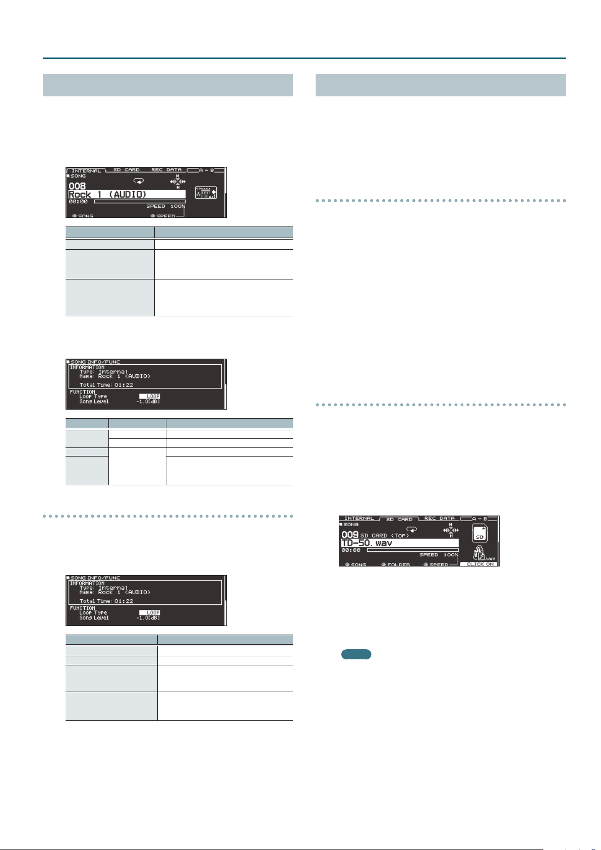
Viewing song information
1. In the SONG screen, select a song (p. 14).
2. Press the PAGE [DOWN] button.
The SONG INFO/FUNC screen appears.
Display Explanation
Type Song type
Name Song name
Folder
Total Time
Song save location
In the case of an SD card, the save location
on the SD card is shown.
Song playback time
* Not shown for songs containing only a
drum performance.
Playing back the click track along with the song
1. In the SONG screen, press the [F2] (SD CARD) button
(p. 14).
2. Use the [R2] knob, [–] [+] buttons, or the dial to select the
song that you want to play back together with the click
track.
In the case of the example, select the song “TD-50.w av .”
3. Press the [F5] button to specify “CLICK ON.”
4. Press the [
The click track plays together with the song playback.
To adjust the volume of the click track, turn the [CLICK] knob.
In the case of the example, you can use the [SONG] knob to adjust
the volume of “TD-50.wav” and use the [CLICK] knob to adjust the
volume of “TD-50_Click.wav.”
MEMO
s
] button.
5 To mute the click track, press the [F5] button to specify
“CLICK OFF.”
5 You can also output the click track only to headphones
(p. 42).
3. Press the PAGE [UP] button to return to the SONG screen.
15
Page 16

Performing
Rhythm Training (QUIET COUNT)
The TD-50 provides a “Quiet Count” function that’s an ideal way to
develop your sense of tempo.
Quiet count is a training function that helps you keep the tempo
on your own. For the rst several measures, the click sounds
at the specied volume, but for the next several measures the
volume decreases, becoming nearly inaudible. This cycle of several
measures continues until you stop the function.
1. In the CLICK screen (p. 13), press the [F4] (QUIET CNT)
button to start training.
5 The click will sound during the rst few measures. When you
reach the last measure during which the click will sound, the
screen will indicate “Ready.”
5 When the click stops sounding, the screen indication will
change to “Quiet.” Continue striking the pads during this time.
5 After the Quiet region, the proportion of your strikes that were
played at an accurate tempo are shown as a “%” value.
Registering/Recalling Favorite Drum Kits (FAVORITE)
You can register frequently-used drum kits as “favorites” for instant
recall.
Registering a favorite
1. Select the drum kit that you want to register (p. 13).
2. In the DRUM KIT screen (p. 13), press the [F5] (MENU)
button.
3. Press the PAGE [UP] button to access page 1
(KIT SETTINGS).
4. Press the [F3] (FAVORITE) button.
5. Turn the [R2] knob to turn favorites “ON.”
6. Press the [KIT] button to return to the DRUM KIT screen.
Drum kits that are registered as a favorite will show an icon in the
DRUM KIT screen.
2. To stop training, press the [F5] (STOP) button to return to
the CLICK screen.
Quiet Count settings
In the QUIET COUNT screen, press the [F2] (SETUP) button to access
the settings screen.
Parameter Value Explanation
Specify the length (measures) of
Measures 2, 4, 8, 16 (Measures)
Of the measures specied by “Measures,” this setting species
the length of the measures that will be “Quiet.”
RANDOM
Quiet
1, 2, 4
the interval for which the click will
alternate between “Sounding” and
“Quiet.”
The length of the Quiet interval will
randomly change each time.
Species the length (number of
measures) of the Quiet interval.
* You can’t specify a length that’s
more than half the length
specied by Measures.
Recalling a favorite
1. In the DRUM KIT screen, turn the [R2] (FAVORITE) knob.
A list of drum kits that are registered as favorites is displayed.
2. Select the drum kit that you want to recall, and press the
[F5] (OK) button.
The TD-50 switches to the selected drum kit.
MEMO
To remove “favorite” registration from a drum kit, turn the
favorite setting “OFF.”
16
Page 17

Recording
Recording a Performance
You can easily record your own performance and play it back.
* If you want to record on an SD card, you must rst insert an SD
card (p. 8).
Recording Your Drum Performance
Here’s how to record your drum performance.
Recording
1. In the DRUM KIT screen (p. 13), press the [
The RECORDER screen appears; the TD-50 is in record-standby
condition.
MEMO
If you want to record along with a click, sound the click (p. 13).
2. Press the [F5] button to select “DRUM only.”
3. Turn the [R1] knob to select the recording destination.
Display Explanation
TEMPORARY
SD#01–99
MEMO
5 If it is OK to overwrite a recording destination that already
contains recorded data, turn the [R2] knob to add a check
mark to “Overwrite.” If the check mark is cleared, previouslyrecorded data will not be accidentally overwritten.
5 Recorded data can be copied (p. 31) or exported (p. 18) to an
SD card.
4. Press the [
5. Press the [
Record onto the TD-50’s temporary area (one song).
* The recorded data in the TEMPORARY area disappears
when you turn o the power.
Record onto the SD card (99 songs).
* You can’t select this unless an SD card is inserted in
the TD-50.
s
] button to start recording.
s
] button once again to stop recording.
Playback
t
] button.
Recording Your Performance Along with a Song
You can record your performance along with a song.
Recording
1. Select the song (audio le) (p. 14).
2. Press the [
The RECORDER screen appears; the TD-50 is in record-standby
condition.
t
] button.
3. Press the [F5] button to select “with SONG.”
You can select “with SONG” only for audio le songs.
4. Turn the [R1] knob to select the recording destination.
MEMO
If it is OK to overwrite a recording destination that already
contains recorded data, turn the [R2] knob to add a check mark
to “Overwrite.” If the check mark is cleared, previously-recorded
data will not be accidentally overwritten.
5. Press the [
The TD-50 starts recording and the song starts playing.
6. Press the [
s
] button to start recording.
s
] button once again to stop recording.
Playback
7. The recorded performance plays back.
You can press the [F5] button to specify whether the drum
performance sounds are heard.
* If you recorded while playing back a click track (p. 15) along with
the song, the click track does not play when you play back the
recorded performance.
Deleting Recorded Data
Here’s how to delete recorded data.
1. In the SONG screen (p. 14), press the [F3] (REC DATA)
button.
6. Press the [
The recorded performance plays back.
MEMO
7. Press the [
s
] button.
Recorded data can be viewed in the REC DATA tab. You can also
turn the [R1] knob to select another recorded song, and press
the [s] button to play it.
s
] button to stop playback.
2. Turn the [R1] knob to select the recorded data that you
want to delete.
3. Press the PAGE [DOWN] button.
4. Press the [F3] (DELETE) button.
A conrmation message appears.
If you decide to cancel, select “CANCEL” and press the [ENTER]
button.
5. Select “OK” and press the [ENTER] button.
The recorded data is deleted.
17
Page 18

Recording
Renaming Recorded Data
Here’s how to change the name of recorded data.
1. In the SONG screen (p. 14), press the [F3] (REC DATA)
button.
2. Turn the [R1] knob to select recorded data.
3. Press the PAGE [DOWN] button.
4. Press the [F4] (NAME) button.
The SONG NAME screen appears.
5. Edit the name (p. 25).
You can enter up to 16 characters as the song name.
6. Press the [F5] (EXIT) button to exit the SONG NAME
screen.
Exporting Recorded Data to an SD Card (SONG EXPORT)
5. Turn knobs [R2] or [R3] to specify the export settings (only
if exporting an audio le).
Parameter Explanation
By pressing the [s] button you can preview-play the
recorded data that is produced by the export. While
watching the output level meter, adjust the volume of
the audio le. Positive (+) values increase the volume.
Export Gain
In some cases, the reverberation of the last notes might
Post Export Time
* The sound that is output from the MASTER OUT jacks is
exported as the audio le. Depending on the routing settings
(p. 44), specic sounds might not be exported in some cases.
be cut o in the exported audio le. If so, you can
increase this value to prevent the reverberation from
being cut o.
6. Press the [F5] (EXECUTE) button.
A conrmation message appears.
If you decide to cancel, select “CANCEL” and press the [ENTER]
button.
Data that you recorded in internal memory or on an SD card can be
exported to an SD card as an audio le (WAV) or SMF data.
1. In the SONG screen (p. 14), press the [F3] (REC DATA)
button.
2. Turn the [R1] knob to select the type of export.
3. Press the [F4] (EXPORT) button.
The SONG EXPORT screen appears.
4. Turn the [R1] knob to select the type of export.
Display Explanation
SMF (DRUM ONLY) Export the drum performance as SMF.
WAV (DRUM ONLY)
WAV (DRUM+SONG)
ALL (WAV+SMF)
Export the sound of the drum performance as an
audio le.
Export the sound of the drum performance and
the song as an audio le.
* You can’t select this for recorded data that was
recorded as “DRUM only.”
If you recorded as “DRUM only”
The drum performance is exported as an audio
le and as SMF.
If you recorded as “with SONG”
Drum performance sounds are exported as an
audio le and as SMF, and the drum performance
sounds and the sound of the song are exported as
an audio le.
7. Select “OK” and press the [ENTER] button.
The export starts.
The exported data is saved in the “EXPORT folder” (p. 40).
NOTE
Never do the following operations while export is progressing.
These operations might cause all recorded data to be lost.
5 Turning o the power
5 Removing the SD card
5 Striking a pad
MEMO
5 If exported data of the same name already exists, the
message “Overwrite it?” appears. If it is OK to overwrite the
data, select “OK” and press the [ENTER] button. If you decide
to cancel the operation, select “CANCEL” and press the
[ENTER] button; then change the name and export the data.
5 If you decide to cancel the export without completing it,
press the [F4] (ABORT) button.
5 When you export a drum performance as SMF data, the data
is exported using the note numbers specied by the drum
kit and the MIDI settings in SETUP. For details, refer to “Data
List” (PDF).
18
MEMO
You can press the [F4] (NAME) button and assign a name for the
exported le.
Page 19

Customizing a Kit
Saving the settings
On the TD-50, your edits are saved automatically, so you
don’t have to perform any operation to save the settings.
Settings are also saved when you turn o the power.
Editing an Instrument (INSTRUMENT)
Here’s how to edit an individual instrumental sound such as the
snare drum or kick drum.
The TD-50 lets you reproduce the way in which the sound of an
instrument is aected by its shape and size. You can shape your
sound in an intuitive way, just as if you were selecting a desired
drum head and tuning it, or adding muing (muting).
You can also apply eects such as mic settings and transients.
Reference
For details on the parameters that can be edited, refer to “Data
List” (PDF).
MEMO
An audio le that you created on your computer can be loaded
from an SD card into the TD-50, and played as an instrument
(p. 27).
1. Press the [INSTRUMENT] button.
The INSTRUMENT screen appears.
Selecting an Instrument
1. Press the [INSTRUMENT] button.
2. Press the PAGE [UP] button to access page 1
(INSTRUMENT).
3. Press the [F1] (INST) button.
Instrument group
Instrument name
Instrument number
4. Select the pad that you want to edit (p. 20).
5. Turn the [R1] knob to select an instrument.
MEMO
When the cursor is located at “instrument number” or
“instrument group,” you can press the [ENTER] button to see the
instrument list.
H&R icon (shown only if H&R is “ON”)
Pad location (head/rim/bell)
[F5] (H&R) button
Instrument parameters
Pad to edit
* The displayed content and tabs dier depending on the
instrument.
2. Select the pad that you want to edit (p. 20).
3. Use the PAGE [UP] [DOWN] buttons and function buttons
to select the item that you want to edit.
* The parameters that you can edit depend on the pad and
instrument.
4. Use cursor buttons to select a parameter, and use the [–]
[+] buttons or the dial to edit the value.
MEMO
For some parameters, you can also use the rotary knobs to edit
the value.
5. Press the [KIT] button to return to the DRUM KIT screen.
MEMO
You can copy the settings of an instrument (p. 31).
6. Press the [KIT] button to return to the DRUM KIT screen.
Reference
For details on the instruments that you can select, refer to “Data
List” (PDF).
Selecting an instrument for each strike location
([F5] (H&R) button)
In a screen where the [F5] (H&R) button is shown, you can choose
whether instruments for areas such as the head and rim are
selected together as a set (ON) or independently (OFF).
[F5] (H&R)
button
ON
OFF
Explanation
Instruments for areas such as head and rim are selected
as a set.
As appropriate for the selected instrument, the
recommended instruments are selected as a set.
* If the same parameter exists within the instruments that
are selected as a set, they are automatically set to the
same value.
* Depending on the instrument, the same instrument
might be selected for all areas such as head and rim.
Instruments are selected individually for each struck area,
such as the head and the rim.
19
Page 20

Customizing a Kit
Choosing a Pad to Edit
Choosing by hitting a pad
To edit the settings for a pad, strike that pad to select it.
To select the rim of a pad, strike the rim.
Choosing with the SELECT [K] [J] buttons
You can also use the SELECT [K] [J] buttons to
select the pad (trigger input number) to edit.
When using a pad that provides rim support, the
[RIM] button lets you choose whether to make
settings for the head or for the rim. When using a
pad that provides three-way trigger support, this
button switches between head, rim, and bell.
The [RIM] button is lit if the rim or bell is selected.
Preventing the currently edited pad from changing
(Trigger Lock)
If you want to audition your performance sounds while you edit the
instruments, you can specify that the currently edited pad does not
change even if you strike another pad.
1. Press the [LOCK] button to make it light.
The pad you’re editing is locked.
* The pad remains locked even if you use MIDI messages to switch
pads.
Adjusting the Mic Settings (MIC POSITION)
You can edit the mic position and volume for each instrument.
* For some instruments, these settings are not available.
1. Press the [INSTRUMENT] button.
2. Select the pad that you want to edit.
3. Press the PAGE [UP] [DOWN] button to access page 2
(MIC POSITION).
4. Use cursor buttons to select a parameter, and use the [–]
[+] buttons or the dial to edit the value.
Parameter Value Explanation
MIC POS tab
Mic Position
ELEMENT tab
Overhead -INF–+6.0 dB Volume of overhead mic
Room -INF–+6.0 dB Volume of room mic
WIDTH tab
Mic Width -5–+5 Spread of the overhead mic and room mic
OUTSIDE4–
STANDARD–
INSIDE4
Tonal change caused by mic position
2. To defeat the lock, press the [LOCK] button to make it go
dark.
MEMO
Even if the [LOCK] button is lit, you can use the SELECT [K] [J]
buttons to change the pad that you’re editing.
Auditioning the Sound of a Pad ([PREVIEW] button)
You can press the [PREVIEW] button to audition the sound of the
currently selected pad.
The volume changes depending on how strongly you press the
button. You can also x the volume. For details, refer to “Data List”
(PDF).
MEMO
5 By holding down the [SHIFT] button and pressing [PREVIEW],
you can audition a variety of sounds depending on the
combination of the currently selected pad and instrument.
(For example, you could audition the sound of the snare
head’s outer circumference, a shallow rim shot, or the hi-hat
close sound.)
5 By using the SELECT [K] [J] buttons to select a trigger input
number, you can audition the sound even if that pad is not
connected to the TD-50.
Adjusting the Attack and Release (TRANSIENT)
You can adjust the attack and release (transient) for each
instrument.
* For some instruments, these settings are not available.
1. Press the [INSTRUMENT] button.
2. Select the pad that you want to edit.
3. Press the PAGE [UP] [DOWN] button to access page 3
(TRANSIENT).
4. Use cursor buttons to select a parameter, and use the [–]
[+] buttons or the dial to edit the value.
Parameter Value Explanation
[F4] button
Time 1–10 Time over which the attack changes
Attack -100–+100 Adjusts the attack
Release -100–+100 Adjusts the release
Gain -12.0–+6.0 dB
OFF,
TRANSIENT ON
Turns the transient eect on/o.
Adjusts the volume following transient
adjustment
20
Page 21

Customizing a Kit
Layering Instruments (SUB INSTRUMENT)
You can layer the main instrument with a sub instrument so
that they are heard together. You can also switch between two
instruments according to the force of your strike, or vary the
balance between them.
1. Press the [INSTRUMENT] button.
2. Select the pad that you want to edit (p. 20).
3. Press the PAGE [DOWN] button to access page 4
(SUB INSTRUMENT).
4. Press the [F1] (SUB INST) button.
The SUB INSTRUMENT screen appears.
Main instrument name
Sub instrument group
Sub instrument name
Sub instrument parameters
Selecting a sub instrument
5. Move the cursor to the sub instrument or the sub
instrument group, and use the [–] [+] buttons or the dial
to select a sub instrument.
Turning the sub instrument on/o
6. Press the [F4] button to turn the sub instrument on/o.
Sub instrument settings
7. Use cursor buttons to select a parameter, and use the [–]
[+] buttons or the dial to edit the value.
Parameter Explanation
Layer Type
Fade Point
Sub
Volume
These parameters specify how the sub instrument will be sounded.
Volume
MIX
Volume
FADE1
Volume
FADE2
FADE3
Volume
SWITCH
Species the force of the strike at which the sub instrument begins
to be sounded.
If this is “1,” the sub instrument is sounded by a strike of any force.
If this is “127” (“127+32” for a pad that supports digital connection),
the sub instrument is sounded only by the strongest strike.
* This is not available if Layer Type is “MIX.”
-INF–
Adjusts the volume of the sub instrument.
+6.0 dB
The main instrument (A) and
sub instrument (B) always sound
together as a layer.
Playing
Dynamics
The sub instrument (B) is added as
a layer only if the strike is stronger
than “Fade Point.”
Playing
Dynamics
If the strike is stronger than “Fade
Point,” the sub instrument (B) is
added as a layer according to the
strength of that strike.
FADE2:
At 127 or higher, the main
instrument (A) and sub instrument
(B) are the same volume.
Playing
Dynamics
FADE3:
At 127+32, the main instrument
(A) and sub instrument (B) are
the same volume (for pads that
support digital connection).
Strikes weaker than “Fade Point”
sound the main instrument (A),
and strikes stronger than “Fade
Point” switch to sound the sub
Playing
instrument (B).
Dynamics
MEMO
The indication of Layer Type is dierent for a pad that is
connected to a TRIGGER IN jack than for a pad that supports
digital connection.
For a pad that is connected to a TRIGGER IN jack
For a pad that supports digital connection
Reference
For details on other settings, refer to “Data List” (PDF).
8. Press the [KIT] button to return to the DRUM KIT screen.
21
Page 22

Customizing a Kit
Simulating the Ambience of a Performance Space (AMBIENCE)
This simulates the reverberation or acoustics of a location in which
you’re playing the drums (ambience).
By adjusting settings such as room ambience (the type and size
of the room), and reverb (reverberation), you can give your drum
sound more naturalness and presence.
Reference
For details on the parameters that can be edited, refer to “Data
List” (PDF).
1. Press the [AMBIENCE] button.
2. Use the PAGE [UP] [DOWN] buttons to access the editing
screen.
AMBIENCE screen
ROOM screen
Editing the Mixer (MIXER)
Here you can adjust the volume of each pad and apply various
eects to the sound.
Reference
For details on the parameters that can be edited, refer to “Data
List” (PDF).
1. Press the [MIXER] button.
The Mixer setting screen appears.
2. Select the pad that you want to edit (p. 20).
3. Edit the mixer settings.
4. Press the [KIT] button to return to the DRUM KIT screen.
Specifying the Volume and Pan of Each Pad
You can adjust the volume and pan (stereo position) for each pad.
1. Press the [MIXER] button.
2. Press the PAGE [UP] button to access page 1
(MIXER VOLUME).
REVERB screen
STEREO ENHANCER screen
3. Edit the settings of the ambience.
4. Press the [KIT] button to return to the DRUM KIT screen.
Turning ambience on/o
1. Press the [AMBIENCE] button.
2. Press the PAGE [UP] button to access page 1 (AMBIENCE).
3. Press the [F1]–[F3] button to turn the setting on/o.
Button Explanation
[F1] button Turns room ambience on/o.
[F2] button Turns reverb on/o.
[F3] button Turns stereo enhancer on/o.
MEMO
You can copy ambience settings (p. 31).
3. Press one of the [F1] (VOLUME)–[F4] (KIT VOL) buttons to
select the item that you want to set.
4. Select the pad that you want to edit (p. 20).
You can also use the cursor buttons to make a selection.
5. Use the [–] [+] buttons or the dial to edit the value.
Parameter Value Explanation
[F1] (VOLUME) button
Volume -INF–+6.0 dB Volume of each pad
[F2] (PAN) button
Pan L30–CTR–R30 Stereo position of each pad
[F3] (MIN VOL) button
Pad Minimum
Volume*
Pad
Maximum
Volume*
[F4] (KIT VOL) button
Kit Volume
Pedal HH
Volume
XStick
Volume
* You can use the cursor [H] [I] buttons to switch between
selecting the Pad Minimum Volume and Pad Maximum Volume.
0–15
-5–0
-INF–+6.0 dB
Minimum volume of each pad
This lets you increase the volume of the
softest hits while preserving the volume of
the strongest hits. This can make it easier
to hear ghost notes on the snare or legato
notes on the ride cymbal.
Maximum volume of each pad
This lets you decrease the volume of
the strongest hits while preserving their
nuances.
You can limit the volume while preserving
the nuances of the strongest hits.
* This is available only for pads that
support digital connection and for input
from the MIDI IN connector.
Drum kit volume
Pedal hi-hat volume
Cross-stick volume
22
Page 23

Customizing a Kit
MEMO
5 If you press the [F5] (H&R) button to turn it “ON,” you can
simultaneously make settings for the head area and rim area,
etc.
5 You can also set “Kit Volume” in the KIT SET TINGS screen
(VOLUME tab).
5 You can copy the MIXER VOLUME and MIXER PAN settings
(p. 31).
Applying Eects
For each pad, you can adjust the way in which its volume changes
(pad compressor) and adjust its tone (pad equalizer), or apply up to
three eects to the entire drum kit (multi-eect).
Reference
For details on the parameters that can be edited, refer to “Data
List” (PDF).
1. Press the [MIXER] button.
2. Use the PAGE [UP] [DOWN] buttons to access the edit
screen.
PAD EQ screen
Adjusting the Overall Sound (MASTER COMPRESSOR/MASTER EQ)
You can make settings for the stereo compressor/limiter
(master comp) and four-band parametric equalizer (master EQ) that
are applied to the nal stage of the master output.
* The master comp and EQ eect is not applied to the DIRECT
OUT jacks.
* If the routing setting (p. 44) Master Out is set to “DIRECT,” master
compressor and master EQ eects are not applied to the sound
that is output from the MASTER OUT jacks.
Reference
For details on the parameters that can be edited, refer to “Data
List” (PDF).
Using the master comp
5 When used as a compressor, this allows you to raise the overall
loudness of the drums by compressing brief peaks in the sound.
This lets the sound project better, without being buried in the
mix by the other instruments.
5 When used as a comp-limiter, this lets you increase the
recording level while limiting the maximum input to the
recording device.
5 If you’re using a small monitor amp, you can use this eect as a
limiter so that the peaks of the drum sound are limited, making
the sound less likely to distort.
PAD COMP (COMPRESSOR) screen
MFX (MULTI EFFECT) screen
3. Edit the eect settings.
Turning eects on/o
1. Press the [MIXER] button.
2. Use the PAGE [UP] [DOWN] buttons to access the edit
screen.
3. Press a function button to turn the setting on/o.
Screen Button Explanation
PAD EQ screen [F4] button Turns pad equalizer on/o.
PAD COMP
(COMPRESSOR) screen
MFX (MULTI EFFECT)
screen
[F4] button Turns pad compressor on/o.
[F5] button
Turns on/o the multi-eect 1–3
selected by the [R1] knob.
Using the master EQ
5 This lets you adjust the tonal character by boosting or cutting
each of the four bands (LOW/MID1/MID2/HIGH).
5 You can also use this to make compensations in the tone when
using the master comp.
1. Press the [MIXER] button.
2. Use the PAGE [UP] [DOWN] buttons to access the edit
screen.
MASTER COMP screen
MASTER EQ screen
3. Edit the eect settings.
Turning the master compressor and master EQ on/o
1. Press the [MIXER] button.
MEMO
You can copy pad equalizer, pad compressor, and multi-eect
settings (p. 31).
2. Use the PAGE [UP] [DOWN] buttons to access the edit
screen.
3. Press a function button to turn the setting on/o.
Screen Button Explanation
MASTER COMP screen [F4] button Turns master comp on/o.
MASTER EQ screen [F4] button Turns master EQ on/o.
23
Page 24

Customizing a Kit
Comparing with or Reverting to the Unedited Drum Kit (SNAPSHOT)
You can temporarily save the currently-edited drum kit, and
compare it with the current settings or revert back to it (snapshot).
Save temporarily
(STOCK)
Current drum kit
(CURRENT)
Edit
1. Select the drum kit that you want to edit.
When you select a drum kit, the data of the selected drum kit is
stored in “UNDO.”
2. When you want to temporarily save the settings of the
currently-edited drum kit, press the [SNAPSHOT] button.
The SNAPSHOT screen appears, and the current drum kit (CURRENT)
is selected.
Immediately
after selecting
drum kit (UNDO)
9. Select “OK” and press the [ENTER] button.
The current drum kit settings return to the settings of the drum kit
that you selected in step 7.
10. Press the [KIT] button to return to the DRUM KIT screen.
Editing a Drum Kit (MENU)
Here’s how to make settings such as the volume of the drum kit and
the illumination color of the controls.
Reference
For details on the parameters that can be edited, refer to “Data
List” (PDF).
1. In the DRUM KIT screen (p. 13), press the [F5] (MENU)
button.
The menu screen appears.
2. Edit the settings of the drum kit.
3. Press the [F5] (SAVE) button.
The current drum kit settings are saved in STOCK.
MEMO
By holding down the [SHIFT] button and pressing the
[SNAPSHOT] button, you can save the current drum kit settings
in STOCK without entering the SNAPSHOT screen.
4. Press the [EXIT] button to exit the SNAPSHOT screen, and
edit the drum kit.
* When you switch drum kits, the settings saved in STOCK are
deleted.
5. Press the [SNAPSHOT] button.
6. Use the [F1]–[F3] buttons to switch between the saved
drum kits, and play them to compare.
Button Explanation
[F1] (CURRENT) button Current drum kit settings
[F2] (STOCK) button Drum kit settings saved in STOCK
[F3] (UNDO) button Settings immediately after selecting the drum kit
7. If you want to return the current drum kit settings to the
state immediately after selecting a drum kit or STOCK,
press the [F2] or [F3] button to select the drum kit settings
to which you want to return.
If you want to continue with the current drum kit settings, press the
[KIT] button to return to the DRUM KIT screen.
8. Press the [F4] (RESTORE) button.
A conrmation message appears.
3. Press the [KIT] button to return to the DRUM KIT screen.
MEMO
You can copy a drum kit (p. 31).
Setting the Volume
Here’s how to set the volume of the drum kit.
1. In the DRUM KIT screen (p. 13), press the [F5] (MENU)
button.
2. Press the PAGE [UP] button to access page 1
(KIT SETTINGS).
The KIT SETTINGS screen appears.
3. Press the [F1] (VOLUME) button.
Volume of the drum kit
Output monitor
Shows the output level from the MASTER OUT jacks,
PHONES jacks, and DIRECT OUT jacks.
4. Use the [–] [+] buttons or the dial to edit the value.
Parameter Value Explanation
Kit Volume -INF–+6.0 dB Volume of the drum kit
MEMO
You can also set Kit Volume in the MIXER DRUM KIT VOLUME
screen (KIT VOL tab) of the MIXER (p. 22).
If you decide to cancel, select “CANCEL” and press the [ENTER]
button.
24
Page 25

Customizing a Kit
Specifying the Illumination Color of the [KIT] Button and Knobs
For each kit, you can change the illumination color of the [KIT]
button and knobs.
This provides a useful way to distinguish between drum kits; for
example you could assign dierent colors to drum kits of dierent
genres, or use the color as a guideline when editing instruments.
1. In the KIT SETTINGS screen, press the [F2] (COLOR) button.
2. Use the cursor buttons, [–] [+] buttons, or the dial to select
the illumination color.
Value 1–10
Renaming the Drum Kit
Here’s how to rename the currently selected drum kit.
1. In the KIT SETTINGS screen, press the [F4] (NAME) button.
The DRUM KIT NAME screen appears.
2. Edit the name.
You can enter a kit name (upper line) of up to 12 characters, and a
sub-name (lower line) of up to 16 characters.
Controller Explanation
Cursor buttons
[–] [+] buttons, dial Change the character.
[R1] (ABC) knob Select uppercase characters.
[R2] (abc) knob Select lowercase characters.
[R3] (123) knob Select numerals.
[F3] (INSERT) button Insert a space at the cursor location.
[F4] (DELETE) button Delete the character at the cursor location.
Move the cursor to the character that you
want to change.
Performing with Brushes
You can specify whether you’re performing with sticks or with
brushes.
* This is supported starting with program version 1.05. Refer to
the Roland website for the latest information.
http://www.roland.com/support/
1. In the DRUM KIT screen (p. 13), press the [F5] (MENU)
button.
2. Press the PAGE [UP] [DOWN] button to access page 2
(KIT SETTINGS 2).
3. Press the [F1] (BRUSH) button.
4. Use the [–] [+] buttons or the dial to edit the value.
Parameter Value Explanation
Brush Switch
If Brush Switch is “ON,” the brush icon is shown in the DRUM KIT
screen.
MEMO
Brush performance is available in the following cases.
5 When you select an instrument that supports brush
performance, and assign it to the head of the snare.
5 When you connect a mesh pad to the TRIGGER IN jack
(SNARE), or connect a pad that supports digital connection
to a DIGITAL TRIGGER IN port, and set assign to “SNARE.”
OFF When performing with sticks
ON When performing with brushes
3. Press the [F5] (EXIT) button to exit the DRUM KIT NAME
screen.
25
Page 26

Customizing a Kit
Specifying the Tempo for Each Kit
When you select a drum kit, the tempo you specify here is
automatically applied.
1. In the DRUM KIT screen (p. 13), press the [F5] (MENU)
button.
2. Press the PAGE [UP] [DOWN] button to access page 2
(KIT SETTINGS 2).
3. Press the [F2] (TEMPO) button.
4. Use the [–] [+] buttons or the dial to edit the value.
Parameter Value Explanation
Use a common tempo (p. 13) for the
OFF
Kit Tempo
ON
Tempo 20–260 Tempo specied for each drum kit
If you select a drum kit whose Kit Tempo is “ON,” the tempo is shown
in the DRUM KIT screen.
entire TD-50
The tempo does not change when you
switch drum kits.
Individually specify a tempo for each
drum kit
When you select a drum kit whose Kit
Tempo setting is “ON,” the tempo of
that drum kit is applied to the current
tempo.
4. Select the pad that you want to edit (p. 20).
5. Use the [–] [+] buttons or the dial to edit the value.
Muting the sound of a specic pad when you strike a
pad (mute group)
Mute group settings let you specify that when you strike a pad,
other pads in the same mute group are muted (silenced).
For example, you could assign user samples to the instruments of
each pad, and make mute group settings so that you can switch
between user samples by striking dierent pads.
1. In the DRUM KIT screen (p. 13), press the [F5] (MENU)
button.
2. Press the PAGE [UP] [DOWN] button to access page 3
(KIT PAD CTRL).
3. Press the [F4] (MUTE GRP) button.
The MUTE GROUP screen appears.
4. Select the pad that you want to edit (p. 20).
You can also use the cursor buttons to select a pad.
If the tempo of an individual drum kit is set dierently than the
overall tempo of the TD-50, an “*” is shown before the tempo.
Controlling Tonal Change
You can use a pedal to change the pitch, or adjust the tone
according to the position of your strike on the pad.
Reference
For details on the parameters that can be edited, refer to “Data
List” (PDF).
1. In the DRUM KIT screen (p. 13), press the [F5] (MENU)
button.
2. Press the PAGE [UP] [DOWN] button to access page 3
(KIT PAD CTRL).
3. Use the [F1] (PEDAL BEND)–[F4] (MUTE GRP) buttons to
select the item that you want to edit.
Button Explanation
[F1] (PEDAL BEND)
button
[F2] (POSITION)
button*1
[F3] (POS AREA)
button*1
[F4] (MUTE GRP)
button
*1 This supports the following trigger inputs.
5 SNARE
5 TOM1–4
5 The bow (head) of RIDE
5 AUX1–4
* Depending on the pad that is connected or the instrument that
is selected, there might be cases in which this has no eect.
26
Species the amount of pitch change that occurs
according to the depth to which you press the hi-hat
pedal.
Turns on/o tonal changes that occur depending on
your strike location or the nuances of your rim shots.
Species the striking area for the head or rim.
Mutes the sound of a specic pad when you strike the
pad (mute group).
5. Use the cursor buttons, [–] [+] buttons, or the dial to make
mute group settings.
Parameter Value Explanation
MUTE SEND
- (OFF), 1–8
MUTE RECEIVE
When you specify a mute group, an arrow indicates the pads that
are muted when you strike the currently selected pad, and the pads
that when struck will mute the currently selected pad.
MEMO
To clear all mute groups, press the [F5] (RESET ALL) button.
Specify the mute group number.
When you strike the pad of the number
specied in MUTE SEND, the sound of
the pad assigned to the same number
in MUTE RECEIVE is muted.
* Even if you specify the same
number in MUTE SEND and MUTE
RECEIVE for the same location
(e.g., head or rim) of the same pad,
muting does not occur.
Page 27

Customizing a Kit
Making MIDI Transmit/Receive Settings for Each Pad
You can specify how MIDI messages are transmitted and received
for pad strikes.
Reference
For details on the parameters that can be edited, refer to “Data
List” (PDF).
1. In the DRUM KIT screen (p. 13), press the [F5] (MENU)
button.
2. Press the PAGE [DOWN] button to access page 4
(KIT PAD MIDI).
3. Use the [F1] (NOTE)–[F3] (MIDI CH) buttons to select the
item that you want to edit.
Button Explanation
[F1] (NOTE) button
[F2] (GATE) button Duration of the note transmitted by each pad
[F3] (MIDI CH) button
4. Select the pad that you want to edit (p. 20).
5. Use the [–] [+] buttons or the dial to edit the value.
MEMO
To return to the default values, press the [F5] (DEFAULT) button.
* In order to play a pad from an external MIDI device, the MIDI
note number and MIDI channel of the pad that you want to play
must match the incoming note number and channel.
MIDI note number transmitted and received by
each pad
MIDI channel used to transmit or receive note
messages for each pad
Importing and Playing Audio Files (USER SAMPLE)
Audio les that you created on your computer can be imported
from an SD card into the TD-50, and played as instruments (user
sample function). You can edit the sound of a user sample or apply
eects to it in the same way as other instruments.
Audio les that can be loaded by the TD-50
WAV
Format (extension) WAV (.wav)
Sampling frequency 44.1 kHz
Bit rate 16, 24-bit
Time (for each le) Maximum 180 seconds
* File names or folder names that contain more than 16
characters are not shown correctly. Files and folders using
double-byte characters are also not supported.
Importing an Audio File (IMPORT)
Here’s how to import an audio le into the TD-50 as a user sample.
1. Insert an SD card into the TD-50 (p. 8).
2. Hold down the [SHIFT] button and press the [SETUP]
button.
3. Press the PAGE [UP] button to access page 1
(USER SAMPLE).
4. Press the [F1] (IMPORT) button.
The USER SAMPLE IMPORT screen appears.
Selecting a le from the SD card
Cursor button Function
[H] button
[I] button
[K] button
[J] button
MEMO
5 By pressing the [F4] (PREVIEW) button you can play back the
selected audio le.
5 It is convenient if the audio le to be imported has been
saved in the IMPORT folder of the SD card.
Moves cursor (up)
Moves cursor (down)
Exits a folder
Enters a folder
5. Use the cursor buttons to select an audio le, and press
the [F5] (SELECT) button.
The USER SAMPLE IMPORT (DESTINATION) screen appears.
27
Page 28

Customizing a Kit
6. Use the cursor buttons to select the import-destination
number, and press the [F5] (IMPORT) button.
* If you select a number in which data already exists, the message
“User Sample Exists!” appears. Select a number that contains no
data.
MEMO
By pressing the [F3] (DELETE) button you can delete a
previously-exported user sample.
7. Press the [F5] (IMPORT) button.
A conrmation message appears.
If you decide to cancel, select “CANCEL” and press the [ENTER]
button.
8. Select “OK” and press the [ENTER] button.
The audio le is imported.
Assigning a User Sample to an Instrument and Playing It
1. Press the [INSTRUMENT] button.
Listing the User Samples
Here’s how to view a list of all user samples that have been
imported.
You can audition the sound, specify looping, and edit the name.
1. Hold down the [SHIFT] button and press the [SETUP]
button.
2. Press the PAGE [UP] button to access page 1
(USER SAMPLE).
3. Press the [F2] (SAMPLE LIST) button.
The USER SAMPLE screen appears.
Remaining amount of user sample area
How user
samples are
sounded
User sample number and name
4. Turn the [R1] knob to select a user sample.
MEMO
You can press the [F4] (PREVIEW) button to play back the
selected user sample. If you press the [F4] (PREVIEW) button
once again during playback, the playback stops.
User sample information
2. Press the PAGE [UP] button to access page 1
(INSTRUMENT).
3. Press the [F1] (INST) button.
4. Select the pad that you want to edit (p. 20).
5. Move the cursor to the instrument group, and use the [–]
[+] buttons or the dial to select “USER SAMPLE.”
6. Turn the [R1] knob to select a user sample.
* Only the parameters of the INSTRUMENT screen
(ADVANCED tab) can be edited for an instrument to which a user
sample is assigned.
7. Press the [KIT] button to return to the DRUM KIT screen.
When you strike a pad to which the user sample is assigned, you
hear that user sample.
MEMO
5 You can assign a user sample to the instrument of each pad,
and make mute group settings (p. 26) so that you can switch
between user samples by striking the pads.
5 You can also assign a user sample to a sub-instrument.
Specifying How the User Sample Is Sounded
You can specify how the user sample is sounded when you strike a
pad, for example whether it sounds only once or repeatedly.
1. From the user sample list, select the user sample for which
you want to make the setting.
2. Use the cursor [
and use the [–] [+] buttons or the dial to change the value.
Parameter Value Explanation
Play Type
MEMO
To stop a user sample that continues playing, you can use ALL
SOUND OFF (p. 13) to stop the sound.
J
] button to move the cursor to Play Type,
ONE SHOT
MONO
ONE SHOT POLY
LOOP ALT
When you strike the pad, the currentlyheard sound is silenced before the new
sound is heard. Notes do not overlap.
When you strike the pad repeatedly,
the sounds of the notes are heard
overlapping.
The user sample plays repeatedly
(loop).
Each time you strike the pad, the sound
alternately plays or stops.
28
Page 29

Customizing a Kit
Specifying the Sounded Region of a User Sample
You can specify the region of a user sample that is actually sounded.
1. From the user sample list, select the user sample for which
you want to make settings.
2. Press the [F2] (START/END) button.
3. Use the [R1]–[R3] knobs to edit the settings.
Knob Parameter Explanation
Zooms the waveform display in or out.
You can zoom-in/out on the horizontal
axis by turning the [R1] knob or by
[R1] knob Zoom
[R2] knob Start
[R3] knobs End
holding down the [SHIFT] button and
pressing the cursor [K] [J] buttons.
You can zoom-in/out on the vertical
axis by holding down the [SHIFT]
button and turning the [R1] knob or
using the cursor [H] [I] buttons.
Adjusts the start point (the location at
which the user sample starts playing).
Adjusts the end point (the location at
which the user sample stops playing).
Deleting a User Sample
Here’s how to delete a user sample.
1. From the user sample list, select the user sample that you
want to delete.
2. Press the [F3] (DELETE) button.
A conrmation message appears.
If you decide to cancel, select “CANCEL” and press the [ENTER]
button.
3. Select “OK” and press the [ENTER] button.
The user sample is deleted.
Renaming a User Sample
Here’s how to rename a user sample.
1. From the user sample list, select the user sample that you
want to rename.
Organizing User Samples
Here’s how to renumber the user sample numbers or optimize the
user sample area.
1. Hold down the [SHIFT] button and press the [SETUP]
button.
2. Press the PAGE [DOWN] button to access page 2 (USER
SAMPLE UTILITY).
3. Press one of the [F1] (RENUMBER)–[F3] (DELETE ALL)
buttons to select a function.
A conrmation message appears.
Example) If you select RENUMBER
If you decide to cancel, select “CANCEL” and press the [ENTER]
button.
Button/Explanation
[F1] (RENUMBER) button
Packing user sample numbers forward (RENUMBER)
If you repeatedly import and delete user samples, the numbers will become
discontinuous.
This function lets you pack the user samples forward. The user sample
assignments for drum kits are also updated so that they will sound correctly.
If you execute RENUMBER, the user samples that are assigned to drum kits
will no longer be correctly reproduced if you load previously-saved backup
data (that does not include user samples).
* If you executed RENUMBER, and then load previously-saved backup data
or kit backup data (that does not include user samples), the user samples
assigned to the drum kit will no longer be correctly reproduced.
[F2] (OPTIMIZE) button
Optimizing the user sample area (OPTIMIZE)
If you repeatedly import and delete user samples, the user sample area
might become fragmented, reducing the number of user samples that can
be loaded.
This function optimizes the area so that user samples can be loaded.
NOTE
5 Be sure to back up before executing this (p. 39).
5 This process might take more than an hour in some cases (This will vary
depending on the number and size of the user samples).
5 Never turn o the power while this operation is in progress. If you do so,
the user samples might be lost.
5 In some cases, optimizing might not produce results.
[F3] (DELETE ALL) button
Deleting all user samples (DELETE ALL)
All user samples in the user memory are deleted.
NOTE
All user samples used in drum kits are also deleted. Pads to which a user
sample is assigned will no longer produce sound.
2. Press the [F5] (NAME) button.
3. Edit the name (p. 25).
4. Press the [F5] (EXIT) button to exit the SAMPLE NAME
screen.
4. Select “OK” and press the [ENTER] button.
The selected function is executed.
29
Page 30

Utility Functions
Using the TD-50 with a Computer
You can connect the TD-50 to your computer, and record MIDI and
ten channels of multi-track audio into a DAW. Audio played back by
your computer can also be heard via the TD-50.
2. Move the cursor to Driver Mode, and use the [–] [+]
buttons or the dial to change the value.
Parameter Value Explanation
Use the driver provided by the
GENERIC
Driver Mode
VENDOR
MEMO
The setting takes eect when the TD-50 is powered o and on
again.
operating system.
Operation is limited to USB MIDI.
Use the TD-50’s dedicated driver
provided by Roland.
USB MIDI and USB audio can be used.
USB cable
(sold separately)
NOTE
5 For some types of computer, this might not work correctly.
Refer to the Roland website for details on the operating
systems that are supported.
5 A USB cable is not included. You can purchase one from the
dealer where you purchased the TD-50.
5 Use a USB 2.0 cable.
5 Your computer’s USB port must support USB 2.0 Hi-Speed.
USB Driver Installation and Settings
Installing the USB driver
The USB driver is software that transfers data between the TD-50
and the software on your computer.
In order to transmit or receive audio via USB, the USB driver must
be installed.
MEMO
5 Before you install the USB driver, change the TD-50’s USB
driver setting to “VENDOR.”
5 For details on downloading and installing the USB driver,
refer to the Roland website.
http://www.roland.com/support/
3. Turn the power o, and then on again
Specifying the Output for USB Audio
You can specify the output destination of the USB audio that is sent
from the USB COMPUTER port.
Ten channels from the USB audio output can be multi-track
recorded into a DAW on your computer.
* The LO CUT and ATT (OUTPUT ROUTING (p. 44)) eects do not
apply to the USB audio output. For details on the parameters,
refer to “Data List” (PDF).
MEMO
For details on settings in your DAW, refer to the owner’s manual
of the DAW you’re using.
Specifying the output destination for USB audio
The output destination setting for USB audio is shared with the
output destination setting of the MASTER OUT jacks and the DIRECT
OUT jacks.
You can select a total of 10 channels of output destination from
MASTER OUT L, R, and DIRECT OUT 1–8.
Reference
For more about output destination settings, refer to “Audio
Output Assignments (OUTPUT)” (p. 42).
Adjusting the USB audio output level
Changing the USB driver setting
Here’s how to switch between the TD-50’s dedicated USB driver and
the driver provided by your operating system.
1. In the SETUP MENU 1 screen (p. 42), press the [F2]
(USB AUDIO) button.
The USB AUDIO SETUP screen appears.
30
1. In the SETUP MENU 1 screen (p. 42), press the [F2]
(USB AUDIO) button.
The USB AUDIO SETUP screen appears.
2. Move the cursor to Output Gain, and use the [–] [+]
buttons or the dial to change the value.
Parameter Value Explanation
Adjusts the output level
Output Gain -24–+24 dB
This applies to all USB audio output
that is sent from the USB COMPUTER
port.
Page 31

Utility Functions
Specifying the Input for USB Audio
Here’s how to specify the USB audio input that is input to the USB
COMPUTER port.
This allows audio that is played back by the computer to be heard
from the TD-50.
1. In the SETUP MENU 1 screen (p. 42), press the [F2]
(USB AUDIO) button.
The USB AUDIO SETUP screen appears.
2. Use cursor buttons to select a parameter, and use the [–]
[+] buttons or the dial to edit the value.
Parameter Value Explanation
Adjusts the input level
Input Gain -36–+12 dB
Species the knob that adjusts the input volume of USB
Volume Select
Input MAIN, SUB
MEMO
You can specify the output destination of the sound that is input
via USB audio (p. 42).
audio (Input MAIN, SUB).
OFF The volume is not adjusted by a knob.
SONG The [SONG] knob adjusts the volume.
CLICK The [CLICK] knob adjusts the volume.
This applies to the USB audio inputs
(Input MAIN, SUB) that are input from
the USB COMPUTER port.
Copying Settings (COPY)
The TD-50 lets you copy various settings within the unit or to an SD
card.
You can also exchange settings between a copy-source and copydestination.
NOTE
When you execute a copy operation, the contents of the copydestination are overwritten. If the destination contains settings
that you want to keep, back them up to an SD card (p. 39).
1. Hold down the [SHIFT] button and press the [SD CARD]
button.
The COPY MENU screen appears.
2. Use the PAGE [UP] [DOWN] buttons and the function
buttons to select an item in the copy menu.
Copy menu Explanation
COPY MENU 1
KIT Copy a drum kit (p. 13).
PAD INST Copy a pad’s instrument (p. 19).
INST SET Copy multiple instruments as a set.
SET LIST Copy a set list (p. 33).
COPY MENU 2
VOLUME Copy the MIXER VOLUME (p. 22) settings.
PAN Copy the MIXER PAN (p. 22) settings.
AMBIENCE Copy the ambiance (p. 22) settings.
MFX Copy the multi-eect (p. 23) settings.
COPY MENU 3
TRIGGER Copy the trigger (p. 35) settings.
REC DATA
Copy recorded data (p. 17) to an SD card.
* The copy-source and copy-destination cannot
be exchanged.
3. Copy the settings according to the menu item that you
selected.
Example 1) Copying a drum kit (KIT)
1. In the COPY MENU 1 screen, press the [F1] (KIT) button.
The COPY KIT screen appears.
2. Press one of the [F1] (USER)–[F3] (SD CARD) buttons to
select a function.
Button Explanation
[F1] (USER) button
[F2] (PRESET) button
[F3] (SD CARD) button Copies kits from backup data saved on an SD card.
Copies from user memory. Only if the copy-source
is user, you can exchange the copy-source and
copy-destination.
Copies kits of preset memory. Choose this if you
want to return to the factory-set kit settings.
* User samples that are assigned to a factory-set
kit cannot be copied.
31
Page 32

Utility Functions
3. Use cursor buttons to select the parameters, and use the
[–] [+] buttons or the dial to specify the copy settings.
USER, PRESET
Copy-source
Copy-destination
User sample icon
(shown only if a drum kit that uses
user samples (p. 27) is selected)
SD CARD
Include or don’t include user samples
Copy-source bank number
Copy-destination
* If you are copying backup data that does not include user samples, you
can’t select the “With User Sample” check box.
4. Press the [F5] (COPY) button.
By pressing the [F4] (EXCHANGE) button you can exchange user
memories (USER only).
Copy-source
User sample icon
2. Press one of the [F1] (USER)–[F3] (SD CARD) buttons to
select a function.
Button Explanation
[F1] (USER) button
[F2] (PRESET) button
[F3] (SD CARD) button
Copies from user memory. Only if the copy-source
is user, you can exchange the copy-source and
copy-destination.
Copies instruments of preset memory. Choose this
if you want to return to the factory-set kit settings.
* User samples that are assigned to a factory-set
kit cannot be copied.
Copies instruments from backup data saved on an
SD card.
3. Use cursor buttons to select the parameters, and use the
[–] [+] buttons or the dial to specify the copy settings.
USER, PRESET
Copy-source
Copy-destination
Copied contents (Copy Target)
Instrument set to copy
User sample icon
(shown only if a drum kit that uses
user samples (p. 27) is selected)
SD CARD
Include or don’t include user samples
Copy-source bank number
Copy-source
Instrument set to copy
A conrmation message appears.
If you decide to cancel, select “CANCEL” and press the [ENTER]
button.
5. Select “OK” and press the [ENTER] button.
The drum kit is copied.
Example 2) Copying multiple instruments as a set
(INST SET)
1. In the COPY MENU 1 screen (p. 31), press the [F3]
(INST SET) button.
The COPY PAD INST SET screen appears.
Copy-destination
Copied contents (Copy Target)
* If you are copying backup data that does not include user samples, you
can’t select the “With User Sample” check box.
User sample icon
Instrument set to copy
Value Explanation
KICK/SNR Copy KICK and SNARE.
TOMS 1–4 Copy TOM 1–4.
CYM SET Copy HI-HAT, CRASH 1, 2, and RIDE.
AUX 1–4 Copy AUX 1–4.
Copied contents (Copy Target)
Value Explanation
with Pad EQ/
Comp
Inst/VEdit Only
Pad EQ/Comp
Only
All pad-related settings (such as instrument, V-EDIT,
volume, ambience send, and Pad EQ/Comp) are copied.
Of the pad settings, settings other than Pad Eq/Comp
are copied, such as instrument settings (e.g., instrument,
V-EDIT), volume, and ambience send.
Of the pad settings, only the pad equalizer and pad
compressor settings (p. 23) are copied.
32
Page 33

4. Press the [F5] (COPY) button.
By pressing the [F4] (EXCHANGE) button you can exchange user
memories (USER only).
A conrmation message appears.
Utility Functions
Recalling Drum Kits Successively (SET LIST)
You can specify an order in which drum kits are recalled in 32 steps
(step 1 through step 32). Such an order is called a “set list,” and you
can create 32 set lists.
You can create a set list for the order in which you use drum kits in
a live performance, and then instantly recall the drum kit that you’ll
use next.
If you decide to cancel, select “CANCEL” and press the [ENTER]
button.
5. Select “OK” and press the [ENTER] button.
The instrument is copied.
Set list 1
Drum kit
7
Set list 2
Drum kit
1
Set list 3
Drum kit
3
Drum kit
13
Drum kit
14
Drum kit
8
Creating a Set List
1. Press the [SET LIST] button to make it light.
The SET LIST screen appears, and set list turns on.
Set list number Set list name Step number
STEP 32STEP 2STEP 1
Drum kit
23
STEP 32STEP 2STEP 1
Drum kit
5
STEP 32STEP 2STEP 1
Drum kit
11
Current drum kit
Button Explanation
[F1] (K SET LIST) button
[F2] (SET LIST J) button
[F5] (SETUP) button Create, edit, or rename a set list.
Drum kit at the next step
Select a set list.
Exchanging or renaming set lists
2. Press the [F5] (SETUP) button.
The setup screen appears.
Button Explanation
[F1] (MOVE LIST H) button
[F2] (MOVE LIST I) button
[F4] (NAME) button
[F5] (STEP EDIT) button
Changes the order of the set list at the cursor
position.
Renames the set list at the cursor position
(p. 25).
Edits the steps of the set list at the cursor
position.
33
Page 34

Utility Functions
Editing the steps of a set list
3. Press the [F5] (STEP EDIT) button.
The SETLIST STEP EDIT screen appears.
Step number
Set list number
4. Use the cursor buttons to select each step, and use the [–]
[+] buttons or the dial to specify the drum kit at that step.
Button Explanation
[F4] (DELETE) button
[F5] (INSERT) button
MEMO
If the set list is empty, move the cursor to “END” and use the [–]
[+] buttons or the dial to specify a drum kit.
5. Press the [KIT] button to return to the SET LIST screen.
Drum kit at this step
Step at the cursor position is deleted, and
steps after this point are moved forward one
place.
The same kit is inserted at the cursor
position, and steps after this point are moved
backward one place.
Using Set Lists
Selecting a set list
1. Press the [SET LIST] button to make it light.
The set list function turns on.
2. Press the [F1] (
select the set list that you want to use.
Switching drum kits
1. Use the [–] [+] buttons or the dial to select drum kits in the
order of the specied steps.
2. When you’ve nished playing, press the [KIT] button or
the [EXIT] button to make the [SET LIST] button go dark.
The set list function turns o.
MEMO
5 You can assign the appropriate function to a footswitch or
5 If there are discrepancies between the volumes of each kit,
K
SET LIST) button or [F2] (SET LIST J) button to
pad, and use it to recall set lists or drum kits. For details, refer
to “Assigning Functions to Foot Switches or Pads (CONTROL)”
(p. 45).
press the [MIXER] button and adjust the Kit Volume (overall
volume of the entire kit) (p. 22).
34
Page 35

Settings
Trigger Settings (TRIGGER)
Here’s how to make trigger settings so that the signals from the
pads can be accurately processed by the TD-50.
Specifying the Pad Type
You can specify the type of pad (trigger type) used by each trigger
input of the trigger bank.
Trigger type
The trigger type is a collection of various trigger parameters,
adjusted to values that are appropriate for each pad.
To obtain the optimal settings for the pad used with
each trigger input, specify the model (type) of pad that’s
connected.
Trigger bank
A trigger bank contains an entire set of settings for 14
triggers. You can create eight trigger banks.
Reference
For details on the parameters that can be edited, refer to “Data
List” (PDF).
1. Press the [TRIGGER] button.
2. Press the PAGE [UP] button to access page 1 (TRIG BASIC).
3. Press the [F1] (BANK) button.
The TRIGGER BANK screen appears.
Trigger bank number
Specifying a Digitally-Connected Pad
The rst time that you connect a pad that supports digital
connection to a DIGITAL TRIGGER IN port, you’ll follow the screens
that appear, and specify the trigger input to which the connected
pad is assigned (p. 9).
Here you’ll make settings to change the assignment destination.
* If you specify the same trigger input as a pad that is connected
to a TRIGGER IN jack, the pad that’s connected to that TRIGGER
IN jack won’t produce sound.
* When you execute a factory reset, the connection history and
settings of digitally-connected pads are initialized.
1. Press the [TRIGGER] button.
2. Press the PAGE [UP] button to access page 1 (TRIG BASIC).
3. Press the [F2] (DIGITAL) button.
The DIGITAL TRIGGER IN screen appears.
Connected pad Assignment
4. Use the cursor buttons to select the pad that you want to
specify, and use the [–] [+] buttons or the dial to specify
the assignment.
You can also select a pad by striking it.
If you don’t want to assign the pad to any trigger input, choose
“N/A.”
* You can’t specify multiple instances of the same assignment.
Trigger type
4. Move the cursor to the trigger bank number, and use the
[–] [+] buttons or the dial to select a bank.
5. Select the pad whose settings you want to edit (p. 20).
You can also use the cursor buttons to make a selection.
Pad Explanation
K KICK
S SNARE
T1–4 TOM1–4
HH HI-HAT
C1, 2 CRASH1, 2
R RIDE
A1–4 AUX1–4
6. Use the [–] [+] buttons or the dial to specify the trigger
type.
* You can’t change the trigger type of a trigger input that’s
assigned to a pad that supports a digital connection.
MEMO
When you specify the trigger type, the trigger parameters
(with the exception of certain parameters such as cross-stick
cancel)* are set to optimal values. These values are only general
guidelines; you can make ne adjustments as appropriate
according to how you attach the pad and how you use it.
* For details, refer to “Data List” (PDF).
35
Page 36

Settings
Adjusting the Pad Sensitivity
Because the following settings are automatically set to the
appropriate values for each pad when you specify the trigger type
(p. 35), there is normally no need for you to edit them.
You can edit these settings if you want to make ner adjustments,
or if you want to use an acoustic drum trigger.
1. Press the [TRIGGER] button.
2. Press the PAGE [UP] button to access page 1 (TRIG BASIC).
3. Press the [F3] (SENS) button.
The TRIGGER SENS screen appears.
Velocity meter (Indicates the
force (velocity) of the strike.)
Display Explanation
K KICK
S SNARE
T TOM1–4
H HI-HAT
4. Select the pad that you want to edit (p. 20).
5. Use cursor buttons to select a parameter, and use the [–]
[+] buttons or the dial to edit the value.
Parameter Value Explanation
You can adjust the sensitivity of the
pads to accommodate your personal
playing style.
Sensitivity 1.0–32.0
Rim Gain 0–3.2
MEMO
5 To return to the default values, press the [F5] (DEFAULT)
button. Trigger parameters (with the exception of certain
parameters such as cross-stick cancel)* are set to the default
value.
* For details, refer to “Data List” (PDF).
5 Velocity is displayed with a maximum of 127 for pads that
are connected to a TRIGGER IN jack, or with a maximum
of 127+32 (when MIDI CONTROL HI-Reso Velocity is “ON”)
for pads that support HI-Reso Velocity and are digitally
connected to a DIGITAL TRIGGER port. For details, refer to
“Data List” (PDF).
Increasing this value increases the
sensitivity, so that even soft strikes on
the pad are sounded at high volume.
Decreasing this value decreases the
sensitivity, so that even strong strikes
on the pad are sounded at low volume.
Adjusts the balance between the force
of striking the rim or edge and the
loudness of the sound.
If you increase this value, even soft
strikes on the rim are sounded at high
volume. If you decrease this value, even
strong strikes on the rim are sounded
at low volume.
This is available for pads that support
rim shots.
Display Explanation
C CRASH1, 2
R RIDE
A AUX1–4
Adjusting the Hi-Hat Settings
If you are using a V hi-hat, adjust the oset on the TD-50.
This is necessary in order to correctly detect open/close operations
and pedal movement.
Reference
5 For details on how to adjust the oset, refer to “Making Hi-
hat Settings” (p. 11).
5 Make detailed adjustments to the parameters as necessary.
For details, refer to “Data List” (PDF).
Making Detailed Adjustments for the Trigger
Because the following settings are automatically set to the
appropriate values for each pad when you specify the trigger type
(p. 35), there is normally no need for you to edit them.
Edit these settings only if you want to make detailed adjustments to
the pad’s sensitivity, signal detection, and strike location detection.
Reference
For details on the parameters that can be edited, refer to “Data
List” (PDF).
1. Press the [TRIGGER] button.
2. Press the PAGE [UP] [DOWN] button to access page 2
(TRIG ADVANCED).
The trigger advanced screen appears.
3. Press a [F1] (THRESHOLD)–[F4] (POSITION) button to
select the item that you want to edit.
Button Explanation
[F1] (THRESHOLD)
button
[F2] (RIM) button Edits detailed settings for rim shots.
[F3] (SCAN) button Edits detailed settings for trigger signal detection.
[F4] (POSITION) button Edits detailed settings for strike location detection.
4. Select the pad that you want to edit (p. 20).
5. Use cursor buttons to select a parameter, and use the [–]
[+] buttons or the dial to edit the value.
MEMO
To return to the default values, press the [F5] (DEFAULT) button.
Trigger parameters (with the exception of certain parameters
such as cross-stick cancel)* are set to the default value.
* For details, refer to “Data List” (PDF).
Edits detailed settings for pad sensitivity.
36
Page 37

Settings
Making Detailed Settings for DigitallyConnected Pads
The rst time that you connect a pad that supports digital
connection, the following settings are automatically set to values
that are optimal for each pad, so it is normally not necessary to
specify them.
Edit these settings if you want to make more detailed adjustments.
Reference
For details on the parameters that can be edited, refer to “Data
List” (PDF).
1. In the DIGITAL TRIGGER IN screen (p. 35), press the [F5]
(ADVANCED) button.
The DIGITAL TRIGGER ADVANCED screen appears.
2. To select the pad that you want to specify, use the cursor
buttons or strike a pad.
3. Press the cursor [
Advanced Setting parameters.
4. Use cursor buttons to select a parameter, and use the [–]
[+] buttons or the dial to edit the value.
* The parameters that you can edit will dier depending on the
pad.
MEMO
To return to the default values, press the [F5] (DEFAULT) button.
Trigger parameters (with the exception of certain parameters
such as cross-stick cancel)* are set to the default value.
* For details, refer to “Data List” (PDF).
J
] button to move the cursor to the
Viewing Trigger Information for Each Pad
You can view realtime information that shows the force (velocity)
with which each pad is struck, how far the hi-hat is open, and the
strike position on the snare, ride cymbal, toms, and AUX.
MEMO
Performance data received from the MIDI IN connector is also
shown.
1. Press the [TRIGGER] button.
2. Press the PAGE [DOWN] button to access page 3
(TRIG MONITOR).
3. Press the [F1] (TRIG) button.
The TRIGGER MONITOR screen appears.
Velocity meter
(Indicates the force
(velocity) of the strike.)
4. Strike the pads.
The meter indications in the screen will move in realtime, allowing
you to view the following information.
Display Explanation
HI-HAT
POSITION
INTERVAL
CHOKE
Display Explanation
K KICK
S SNARE
1–4 TOM1–4
H HI-HAT
Shows how far the hi-hat is open. The indicator
will move toward “OPEN” as the hi-hat opens, and
toward “PRESS” as it closes.
Indicates the rim strike position on the snare, ride
cymbal, toms, and AUX. The indicator will move
toward “CENTER” as the strike is closer to the center
of the pad, and toward “OUTER” as the strike is
closer to the edge of the pad.
Indicates the time interval at which the pad is
struck. The farther toward the right, the shorter the
interval. The tonal character of a cymbal or snare
roll changes smoothly.
The “CHOKE” icon appears when the cymbal is
choked.
The CHOKE icon appears when you use the choke
technique on a pad that supports choking.
Display Explanation
C CRASH1, 2
R RIDE
A AUX1–4
37
Page 38

Settings
Eliminate Crosstalk Between Pads (Crosstalk Cancellation)
If two pads are attached to the same stand, the vibration from
one struck pad may cause the other pad to sound without your
intention. This is called “crosstalk.” Crosstalk cancellation is a setting
that prevents this type of crosstalk.
* When the TD-50 is shipped from the factory, it is set for optimal
operation with the separately sold drum stand (MDS-50KV or
MDS-50K), so you will not normally need to change the settings.
You’ll need to make crosstalk cancellation settings in the
following cases.
5 When using a pad conguration not found in the trigger bank
settings (p. 35)
5 When using a drum stand other than the separately sold
drum stand (MDS-50KV or MDS-50K)
5 When using a drum trigger (sold separately)
* In some cases, the acoustic sound from an acoustic drum or
from a monitor speaker might cause a pad to be triggered. In
such cases, adjusting the crosstalk cancelation settings will not
solve the problem. Pay attention to the following considerations
when setting up your equipment.
5 Set up the pads at a distance from the speakers
5 Angle the pads, placing them where they are less likely to be
aected by the sound
5 Increase the Threshold value of the pad (refer to “Data List”
(PDF))
Tips for positioning the pads
You can prevent crosstalk by positioning the pads in a way that
minimizes their susceptibility to an external source of vibration.
Before you adjust the crosstalk cancellation settings, please note
the following points when setting up your system.
5 Don’t place pads in contact with each other.
5 If attaching multiple pads to the same stand,increase the
distance between them.
5 Firmly tighten the knobs that fasten the pad to ensure that the
pad is securely attached to the stand.
Example) Crash 1 is triggered when you strike the
Tom 1 pad
1. Press the [TRIGGER] button.
4. Strike the tom 1 (T1) pad
The crosstalk detection status is shown in the TRIGGER XTALK
MONITOR screen.
The illustration below indicates that tom 2 (T2) and crash 1 (C1)
detected vibration when tom 1 (T1) was struck.
A “H" symbol is shown for pads that are experiencing crosstalk.
Crosstalk occurring
Pads detecting
vibration
Tom 2 (T2)
Crash 1 (C1)
Explanation
Will not sound, because crosstalk cancellation is
active.
Crosstalk is occurring.
By adjusting the crosstalk cancellation value, you
can prevent the sound from being triggered.
5. Press the [F3] (FOCUS) button to move the cursor to C1.
If crosstalk is occurring for multiple pads, each press of the [F3]
(FOCUS) button will move the cursor to another pad that is
experiencing crosstalk.
6. Press the [F4] (SET) button.
In this case, the value is automatically set to “33,” which is the
minimum value that can cancel triggering for crash 1.
Value Explanation
0–80 Strength of crosstalk cancellation
* The value will not exceed 40 when you set crosstalk cancellation
automatically. If you need to set this value above 40, use the [–]
[+] buttons or the dial to edit the value.
7. Repeat steps 5 and 6 to make crosstalk cancellation
settings.
MEMO
You can also use the cursor [K] [J] buttons, [–] [+] buttons, or
the dial to make crosstalk cancellation settings manually.
2. Press the PAGE [DOWN] button to access page 3
(TRIG MONITOR).
3. Press the [F2] (XTALK) button.
The TRIGGER XTALK MONITOR screen appears.
Crosstalk cancellation settings
Pads
38
Page 39

Settings
Backing Up Data to an SD Card (SD CARD)
Settings stored in the TD-50 can be saved (backed up) to an SD
card, or loaded into the TD-50.
Backing Up All Settings (SAVE)
Here’s how all settings stored in the TD-50 can be backed up as a
single set to an SD card (up to 99 sets).
1. Insert an SD card into the TD-50 (p. 8).
2. Press the [SD CARD] button.
3. Press the PAGE [UP] button to access page 1 (SD CARD
BACKUP ALL).
4. Press the [F1] (SAVE) button.
The SD CARD SAVE <BACKUP ALL> screen appears.
5. Make backup settings.
Parameter Explanation
With User Sample
Bank Number Select the backup number.
* If you back up user samples as well, it may take several minutes
to save the data depending on the size of the user samples.
If you don’t back up user samples, and you then delete user
samples or renumber them, the kit won’t be reproduced
correctly even if you load the backup.
Select whether previously-imported user samples
are also backed up.
Loading Backup Data from an SD Card (LOAD)
Here’s how backup data that was saved on an SD card can be
loaded into the TD-50.
1. Insert an SD card into the TD-50 (p. 8).
2. Press the [SD CARD] button.
3. Press the PAGE [UP] button to access page 1 (SD CARD
BACKUP ALL).
4. Press the [F2] (LOAD) button.
The SD CARD LOAD <BACKUP ALL> screen appears.
5. Make load settings.
Parameter Explanation
With User Sample Select whether user samples are also loaded.
Bank Number Select the backup number.
* When you load user samples, the user samples included in
the backup data are overwritten onto the user samples in user
memory. Depending on the size of the user samples, it might
take ten minutes or more to load the data.
* If you are loading backup data that does not include user
samples, you can’t select the “With User Sample” check box.
6. Press the [F5] (LOAD) button.
A conrmation message appears.
6. Press the [F5] (SAVE) button.
MEMO
If you want to assign a name to the backup data, press the [F4]
(NAME) button and assign a name (p. 25).
7. Press the [F5] (EXECUTE) button.
A conrmation message appears.
If you decide to cancel, select “CANCEL” and press the [ENTER]
button.
8. Select “OK” and press the [ENTER] button.
The backup data is saved on the SD card.
If you decide to cancel, select “CANCEL” and press the [ENTER]
button.
7. Select “OK” and press the [ENTER] button.
The backup data is loaded from the SD card.
39
Page 40

Settings
Backing Up Drum Kit to an SD Card (1 KIT SAVE)
Here’s how settings of an individual drum kit stored in the TD-50
can be backed up to an SD card (up to 999 drum kits).
1. Insert an SD card into the TD-50 (p. 8).
2. Press the [SD CARD] button.
3. Press the PAGE [UP] [DOWN] button to access page 2 (SD
CARD BACKUP 1KIT).
4. Press the [F1] (1KIT SAVE) button.
The SD CARD SAVE <1KIT> screen appears.
User sample icon
(shown only if a drum kit that uses
user samples (p. 27) is selected)
5. Make backup settings.
Parameter Explanation
With User Sample
User Select the drum kit that you want to back up.
SD Card Select the backup number.
* If you back up user samples as well, it may take several minutes
to save the data depending on the size of the user samples. If
you do not back up user samples, loading the kit backup data
will not correctly reproduce the drum kit if you have deleted
user samples from the TD-50 after making the backup or if you
have renumbered them.
6. Press the [F5] (SAVE) button.
A conrmation message appears.
Select whether the user samples assigned to
the drum kit are also backed up.
4. Press the [F2] (1KIT LOAD) button.
The SD CARD LOAD <1KIT> screen appears.
User sample icon
(shown only if a drum kit that uses
user samples (p. 27) is selected)
5. Make load settings.
Parameter Explanation
With User Sample
SD Card Select the backup number.
User Select the load-destination drum kit.
* When you load user samples, new user samples are created
even if the same user samples already exist. The newly created
user samples are automatically assigned to the loaded drum kit.
* In order to load user samples, there must be sucient free space
for the user samples.
* If you are loading the kit backup data that does not include user
samples, you can’t select the “With User Sample” check box.
Select whether the user samples saved together
with the drum kit are loaded.
6. Press the [F5] (LOAD) button.
A conrmation message appears.
If you decide to cancel, select “CANCEL” and press the [ENTER] button.
7. Select “OK” and press the [ENTER] button.
The kit backup data is loaded from the SD card.
If you decide to cancel, select “CANCEL” and press the [ENTER] button.
7. Select “OK” and press the [ENTER] button.
The kit backup data is saved on the SD card.
Loading Kit Backup Data from an SD Card (1 KIT LOAD)
Here’s how kit backup data that was saved on an SD card can be
loaded into the TD-50.
1. Insert an SD card into the TD-50 (p. 8).
2. Press the [SD CARD] button.
3. Press the PAGE [UP] [DOWN] button to access page 2 (SD
CARD BACKUP 1KIT).
SD card folder structure
EXPORT folder
Recorded data that was exported is saved here.
IMPORT folder
If there are audio les that you want to import as user
samples, save them in this folder.
Roland folder
The TD-50’s song and backup data is saved here.
TD-50 folder
Backup folder
Backup data is saved here.
Kit folder
Drum kit backup data is
saved here.
SONG folder
Recorded song data is
saved here.
40
Page 41

Settings
Deleting Backup Data from an SD Card (DELETE/1 KIT DELETE)
Here’s how to delete unneeded backup data (including user
samples) from an SD card.
1. Insert an SD card into the TD-50 (p. 8).
2. Press the [SD CARD] button.
3. Use the PAGE [UP] [DOWN] buttons and the function
buttons to select a backup menu item.
Backup menu Explanation
DELETE (page 1 (SD CARD BACKUP ALL)) Deletes backup data.
1 KIT DELETE
(page 2 (SD CARD BACKUP 1KIT))
The SD CARD DELETE screen appears.
Example) When using DELETE
4. Specify the deletion settings.
Parameter Explanation
Bank Number
(when using DELETE)
SD Card (when using 1
KIT DELETE)
Select the backup number that you want to delete.
Select the kit backup number that you want to
delete.
Deletes kit backup data.
Formatting an SD Card (FORMAT)
Here’s how to format an SD card.
* Before using an SD card for the rst time with the TD-50, you
must format the SD card.
NOTE
When you format an SD card, all data on the SD card is erased.
If important data is saved on the SD card, back up the data to
your computer before you proceed with formatting the SD card.
1. Insert an SD card into the TD-50 (p. 8).
2. Press the [SD CARD] button.
3. Press the PAGE [DOWN] button to access page 3
(SD CARD UTILITY).
4. Press the [F3] (FORMAT) button.
The SD CARD FORMAT screen appears.
5. Press the [F5] (FORMAT) button.
A conrmation message appears.
5. Press the [F5] (DELETE) button.
A conrmation message appears.
Example) When using DELETE
If you decide to cancel, select “CANCEL” and press the [ENTER] button.
6. Select “OK” and press the [ENTER] button.
The backup data is deleted from the SD card.
Checking the Usage Status of an SD Card (INFO)
Here’s how to check the number of settings that are saved on the
SD card.
1. Insert an SD card into the TD-50 (p. 8).
2. Press the [SD CARD] button.
3. Press the PAGE [DOWN] button to access page 3
(SD CARD UTILITY).
4. Press the [F1] (INFO) button.
The SD CARD INFO screen appears.
If you decide to cancel, select “CANCEL” and press the [ENTER]
button.
6. Select “OK” and press the [ENTER] button.
The SD card will be formatted.
NOTE
While formatting is in progress, never turn o the power or
remove the SD card.
Parameter Explanation
Backup All Number of saved backup data
1 Kit Number of saved kit backup data
Rec Data Number of saved recorded data
5. Press the [KIT] button to return to the DRUM KIT screen.
41
Page 42

Settings
Settings for the Entire TD-50 (SETUP)
Settings that are common to the entire TD-50, such as the output
destination settings and the footswitch settings, are called “setup”
data.
1. Press the [SETUP] button.
The SETUP MENU screen appears.
2. Use the PAGE [UP] [DOWN] buttons and the function
buttons to select the setup menu that you want to edit.
Setup menu Explanation Page
SETUP MENU 1
OUTPUT Species the output destination of the sounds. p. 42
USB AUDIO Makes USB audio settings. p. 30
OPTION
CONTROL Assigns functions to the footswitch and pads. p. 45
SETUP MENU 2
MIDI Makes MIDI settings. p. 45
AUTO OFF Makes AUTO OFF settings. p. 10
INFO
SETUP MENU 3
FACTORY RESET Returns the TD-50 to its factory settings. p. 46
3. Edit the settings of the menu that you selected.
Makes settings for the [PREVIEW] button, the
MIX IN jacks, and the display.
Displays information about the TD-50 itself,
such as the program version.
p. 44
p. 46
[F3] (MONITOR) button
Monitor the output volume of each jack.
2 page (OTHER OUTPUT)
[F1] (MASTER) button
Specify the ambience and MFX output assignments for the PHONES jacks
and MASTER OUT jacks (when OUTPUT ROUTING Master Out is set to
“NORMAL”).
[F2] (DIRECT) button
Specify the ambience and MFX output assignments for the DIRECT OUT 1–8
jacks and MASTER OUT jacks (when OUTPUT ROUTING Master Out is set to
“DIRECT”).
[F3] (MONITOR) button
Monitor the output volume of each jack.
Audio Output Assignments (OUTPUT)
Here’s how to assign the audio outputs from the MASTER OUT jacks,
DIRECT OUT jacks, and PHONES jacks.
MEMO
The output destination setting for USB audio (p. 30) is shared
with the output destination setting of the MASTER OUT jacks
and the DIRECT OUT jacks.
1. In the SETUP MENU 1 screen, press the [F1] (OUTPUT)
button.
2. Use the PAGE [UP] [DOWN] buttons and the function
buttons to select the audio output that you want to
assign.
1 page (PAD OUTPUT)
[F1] (MASTER) button
Specify each pad’s output assignments for the PHONES jacks and MASTER
OUT jacks (when OUTPUT ROUTING Master Out is set to “NORMAL”).
[F2] (DIRECT) button
Specify each pad’s output assignments for the DIRECT OUT 1–8 jacks and
MASTER OUT jacks (when OUTPUT ROUTING Master Out is set to “DIRECT”).
* For more about the OUTPUT ROUTING Master Out parameter,
refer to “Data List” (PDF).
3. Strike a pad or use the cursor [
K
] [J] buttons to select the
pad or function that you want to edit.
Display Explanation
K KICK
S SNARE
1–4 TOM1–4
H HI-HAT
C CRASH1, 2
R RIDE
A AUX1–4
Display Explanation
AMB Ambience (p. 22)
MFX1–3 Multi-eect 1–3 (p. 23)
SONG Song (p. 14)
CLICK Click (p. 13) and song click track (p. 15) output
MIXIN Sound that is input to the MIX IN jack (p. 14)
USB IN MAIN, SUB
Sound that is input to the USB COMPUTER port
(p. 31)
42
Page 43

Settings
4. Use the cursor [
H
] [I] buttons, [–] [+] buttons, or dial to
select the output destination.
MEMO
To return to the default values, press the [F4] (DEFAULT) button.
If in page 1 (PAD OUTPUT) you selected the [F2] (DIRECT)
button, pressing the [F4] (DEFAULT ) button lets you select the
default values (factory-set state) or another output setting
(STEREO ALL) (supported starting with program version 1.05).
Use the cursor buttons to select “DEFAULT” if you want to return
to the default values (factory-set state) or "STEREO ALL" if you
want to select the other output setting; then press the [F5]
(RESET) button.
5. Press the [KIT] button to return to the DRUM KIT screen.
Output Destination Setting Examples
Here are some examples of output destination settings.
MEMO
The MASTER OUT jacks (XLR type) and DIRECT OUT jacks
(TRS phone type) are balanced. The MASTER OUT jacks
(TRS phone type) are unbalanced (p. 9).
Example 1) Default settings
As the chart below illustrates, the PHONES jacks and the MASTER
OUT jacks will output all sounds. Individual sounds are assigned to
DIRECT OUT 1-8 jacks for individual sound control with a PA system.
Jack Output setting Example destination
PHONES All Monitor headphones
MASTER OUT All Drum monitor
DIRECT OUT 1 KICK
DIRECT OUT 2 SNARE
DIRECT OUT 3 HI-HAT
DIRECT OUT 4 RIDE
DIRECT OUT 5/6 TOM 1–4 (Stereo)
DIRECT OUT 7/8
CRASH 1, 2,
AUX 1–4 (Stereo)
Example 2) Sending the same audio for monitoring and PA
With these settings, the same sound will be output from the
PHONES jacks, the MASTER OUT jacks, and the DIRECT OUT 7/8
jacks.
The sound being monitored by the performer will be the same as
the sound sent to the PA system.
* The master compressor and master EQ eects are not applied to
DIRECT OUT.
Jack Output setting Example destination
PHONES All Monitor headphones
MASTER OUT All Drum monitor
DIRECT OUT 1 – –
DIRECT OUT 2 – –
DIRECT OUT 3 – –
DIRECT OUT 4 – –
DIRECT OUT 5/6 – –
DIRECT OUT 7/8 All PA (external mixer)
PA (external mixer)
Example 3) Performing while listening to a guide
All sound is sent from the PHONES jacks for monitoring.
By outputting CLICK (the click and song click track output) and USB
IN SUB (the sound that is input to the USB COMPUTER port) only
from headphones, the performer alone can hear the guide sound
while they perform.
Jack Output setting Example destination
PHONES
MASTER OUT
DIRECT OUT 1 KICK
DIRECT OUT 2 SNARE
DIRECT OUT 3 HI-HAT
DIRECT OUT 4 RIDE
DIRECT OUT 5/6 TOM 1–4 (Stereo)
DIRECT OUT 7/8
All
CLICK and USB IN
SUB are output
only to PHONES
Output only
SONG and USB IN
MAIN
CRASH 1, 2,
AUX 1–4 (Stereo)
Monitor headphones
PA (external mixer)
43
Page 44

Settings
Making detailed settings for output routing
Here’s how to make detailed settings for output routing to the
MASTER OUT jacks, DIRECT OUT jacks, and PHONES jacks.
Reference
For details on the parameters that can be edited, refer to “Data
List” (PDF).
1. In the SETUP MENU 1 screen (p. 42), press the [F1]
(OUTPUT) button.
2. Press the PAGE [DOWN] button to access page 3
(OUTPUT ROUTING).
The routing screen appears.
3. Press a [F1] (ROUTING)–[F3] (ATT) button to select the
item that you want to edit.
Button Explanation
[F1] (ROUTING) button
[F2] (LO CUT) button
[F3] (ATT) button
Species how the fader, pad equalizer/compressor,
and master out output are applied or routed.
Species whether the low-frequency region is cut
from the output.
The frequency setting is the same for each output.
Species whether an attenuator is applied to the
output from the DIRECT OUT jacks.
If the ROUTING tab’s Master Out setting is “DIRECT,”
this also applies to the MASTER OUT jacks.
For more about the Master Out parameter, refer to
“Data List” (PDF).
Parameter Explanation
PadComp to
Phones
Master Out
When turned “OFF”
5 The pad compressor does not apply to the output from
the PHONES jacks.
5 With settings such as shown in output destination
setting example 2 (p. 43), you can hear the sound with
full dynamics in your monitor headphones as you
perform, yet use the pad compressor to reduce the
dynamics for the drum monitor and the PA.
With the “DIRECT” setting
5 The master compressor and master EQ eects are not
applied to the output from the MASTER OUT jacks,
allowing you to use the MASTER OUT jacks as DIRECT
OUT jacks (the setting of the [MASTER] knob is applied).
This setting also applies to the output via USB audio to
your computer.
5 The PHONES jacks output the sound processed by the
master compressor and master EQ.
5 If you want the output of the MASTER OUT jacks to be
output as direct output, assign the output to MASTER
DIRECT in the PAD OUTPUT screen (DIRECT tab) and the
OTHER OUTPUT screen (DIRECT tab).
Reference
For other settings, refer to “Data List” (PDF).
Other Settings (OPTION)
Here you can make settings for the [PREVIEW] button, the MIX IN
jack, and the display.
Reference
For details on the parameters that can be edited, refer to “Data
List” (PDF).
MEMO
5 To return to the default values, press the [F4] (DEFAULT)
button.
5 The LO CUT and ATT settings do not aect the USB audio
output.
4. Press the [KIT] button to return to the DRUM KIT screen.
Routing parameter setting examples
Parameter Explanation
Fader to Direct
PadEq/Comp to
Direct
When turned “OFF”
5 The output from the DIRECT OUT jacks is not aected
by the panel faders.
The output from the MASTER OUT jacks is not aected
by the panel faders if the OUTPUT ROUTING Master Out
setting is “DIREC T.”
The output of the PHONES jacks is always aected
by the panel faders regardless of the Fader to Direct
setting.
5 Separately from the balance that is adjusted at the PA,
the performer can use the faders at hand to adjust the
balance of the sound that they are monitoring.
When turned “OFF”
5 The output from the DIRECT OUT jacks bypasses the
pad equalizer and pad compressor.
The output from the MASTER OUT jacks bypasses the
pad equalizer and pad compressor if the OUTPUT
ROUTING Master Out setting is “DIRECT.”
5 While the equalizer and compressor for each pad are
adjusted at the PA, the performer can perform with
the sound processed by the pad equalizer and pad
compressor of each drum kit.
1. In the SETUP MENU 1 screen (p. 42), press the [F3]
(OPTION) button.
The option settings screen appears.
2. Press a [F1] (PREVIEW)–[F4] (GUIDE) button to select the
item that you want to edit.
Button Explanation
[F1] (PREVIEW) button
[F2] (MIX IN) button Makes settings for the MIX IN jack.
[F3] (LCD) button Adjusts the contrast of the display.
[F4] (GUIDE) button
Species how the sound is heard when you press
the [PREVIEW] button.
Shows/hides the guide that temporarily appears
when you switch pages.
3. Use cursor buttons to select a parameter, and use the [–]
[+] buttons or the dial to edit the value.
4. Press the [KIT] button to return to the DRUM KIT screen.
44
Page 45

Settings
Assigning Functions to Foot Switches or Pads (CONTROL)
Foot switches (BOSS FS-5U, FS-6; sold separately) or pads that are
connected to the TD-50 can be assigned to control functions such
as switching drum kits or switching set lists.
Reference
For details on the parameters that can be edited, refer to “Data
List” (PDF).
Assigning a function to a footswitch
Connecting an FS-5U
Stereo 1/4” phone type
1/4” phone type x 2
RING
SW 2SW 1
* If you use a mono cable to connect a single FS-5U, it will operate
as SW 2.
* The FS-5L cannot be used.
TIP
POLARITY switch
Assigning functions to pads
You can assign a function to a pad that’s connected to TRIGGER
IN jack 13/AUX3 or 14/AUX4, or to a pad that supports digital
connection and is assigned to AUX3/4.
1. In the SETUP MENU 1 screen (p. 42), press the [F4]
(CONTROL) button.
2. Press the [F2] (PAD CTRL) button.
The PAD SWITCH CONTROL screen appears.
3. Use cursor buttons to select a parameter, and use the [–]
[+] buttons or the dial to edit the value.
MEMO
5 If you don’t want sound to be heard when you strike the pad,
use MIXER VOLUME (p. 22) to set the AUX3 and AUX4 volume
setting to “0.” Alternatively, press the [INSTRUMENT] button
and select “OFF” as the instrument for AUX3 and AUX4 (p. 19).
5 If you want to use a pad to switch drum kits in a set list
(p. 33), assign the function of the pad to “KIT# DEC” or “KIT#
INC,” and press the [SET LIST] button to make it light. (Create
a set list beforehand.)
4. Press the [KIT] button to return to the DRUM KIT screen.
Connecting an FS-6
Stereo 1/4” phone type
Stereo 1/4” phone type
MODE/POLARITY switch
SW 1
SW 2
1. In the SETUP MENU 1 screen (p. 42), press the [F4]
(CONTROL) button.
2. Press the [F1] (FOOT SW) button.
The FOOT SWITCH CONTROL screen appears.
3. Use cursor buttons to select a parameter, and use the [–]
[+] buttons or the dial to edit the value.
MEMO
If you want to use a footswitch to switch drum kits in a set list
(p. 33), assign the function of the footswitch to “KIT# DEC” or
“KIT# INC,” and press the [SET LIST] button to make it light.
(Create a set list beforehand.)
4. Press the [KIT] button to return to the DRUM KIT screen.
MIDI Settings (MIDI)
Here you can make MIDI settings for the entire TD-50.
Reference
For details on the parameters that can be edited, refer to “Data
List” (PDF).
1. In the SETUP MENU 2 screen (p. 42), press the [F1] (MIDI)
button.
The MIDI screen appears.
2. Press a [F1] (BASIC)–[F4] (PROG CHG) button to select the
item that you want to edit.
Button Explanation
[F1] (BASIC) button
[F2] (CONTROL) button
[F3] (SYNC) button Species settings related to MIDI synchronization.
[F4] (PROG CHG)
button
3. Use cursor buttons to select a parameter, and use the [–]
[+] buttons or the dial to edit the value.
4. Press the [KIT] button to return to the DRUM KIT screen.
Makes basic MIDI settings such as specifying the
channel on which the TD-50 transmits and receives
MIDI data.
Species the MIDI messages that are transmitted
or received to indicate the pad striking location or
the position of the hi-hat pedal.
Lets you freely specify the correspondence
between drum kits and the program changes that
are transmitted and received.
45
Page 46

Settings
Viewing Information for the TD-50 Itself (INFO)
Here’s how to view information for the TD-50 unit itself, such as its
program version.
1. In the SETUP MENU 2 screen (p. 42), press the [F3] (INFO)
button.
The information screen appears.
2. Press a [F1] (PROGRAM)–[F4] (DIGITAL) button to select
the item that you want to edit.
Button Explanation
[F1] (PROGRAM)
button
[F2] (SAMPLE) button
[F3] (SD CARD) button
[F4] (DIGITAL) button
Displays the program version.
Displays the number of loaded user samples and
the remaining amount of space for user samples in
user memory.
Displays the number of backup data, kit backup
data, and recorded data that are saved on the SD
card.
Displays the program version of the digital
connection compatible pads that are connected
to the TD-50.
The FUNC button of the selected pad is blinking.
Restoring the Factory Settings (FACTORY RESET)
The “Factory Reset” operation returns all data and settings stored in
the TD-50 to their factory-set condition.
NOTE
When you execute this operation, all data and settings in the TD-50
will be lost. Before you proceed, you should save any important
data and settings to your SD card (p. 39).
1. In the SETUP MENU 3 screen (p. 42), press the [F1]
(FACTORY RESET) button.
The FACTORY RESET screen appears.
MEMO
If you want all user samples to also be returned to their factoryset state, use the [–] [+] buttons or the dial to add a check mark
to “Reset with User Sample.” All user samples in user memory are
overwritten by the factory-set data.
2. Press the [F5] (FACTORY RESET) button.
A conrmation message appears.
3. Press the [KIT] button to return to the DRUM KIT screen.
If you decide to cancel, select “CANCEL” and press the [ENTER]
button.
3. Select “OK” and press the [ENTER] button.
The “Factory Reset” operation will be executed.
46
Page 47

Appendix
List of Displayed Messages
Error Messages
Message Meaning Action
Format SD Card Error! Failed to format the SD card.
Incorrect File! The backup data or the kit backup data is damaged. Do not use this data.
MIDI Buer Full!
MIDI Oine!
No Backup Data! There is no backup data on the SD card. –
No Data!
No SD Card! No SD card is in the SD card slot. Insert an SD card correctly.
Rec Data Exists! Change Rec
Number or Check Overwrite.
Rec Data Full!
Rec Length Too Long!
Sample Length Too Long! The audio le is too long, and cannot be imported. Files longer than 180 seconds cannot be imported.
Sample Length Too Short! The audio le is too short, and cannot be imported.
SD Card is Locked!
SD Card is not connected! No SD card is in the SD card slot. Insert an SD card correctly.
SD Card Media Error!
SD Card Memory Full! There are no empty space on the SD card. Delete unneeded data (p. 41).
System Overload! The TD-50’s processing could not keep up. Reduce the number of notes that play simultaneously.
Unsupported format! The TD-50 does not support this format.
User Sample Does Not Exist! User samples do not exist. Select a location where user samples exist.
User Sample Exists! User samples exist. Delete the user samples, or select a vacant location.
User Sample Import Error!
User Sample Memory Error!
User Sample memory full! There is no free user sample space. Delete unneeded user sample (p. 29).
A large amount of MIDI messages were received in a short time,
and could not be processed completely.
A MIDI cable or USB cable is disconnected (alternatively,
communication with the external MIDI device was interrupted
for some reason).
You attempted to export a song for which recorded data does
not exist.
Recorded data exists.
The storage capacity of the song recorder is full, and recording
has stopped.
Recording stopped because the maximum number of notes that
can be recorded in one song was exceeded.
Recording has stopped because the maximum recordable
length has been exceeded (the recorder of this product records
performance data in units of measures).
The SD card is locked. Unlock the SD card.
The le attribute is read-only. Clear the read-only attribute of the le.
The contents of SD card are damaged.
Failed to save recorded data. Check the lock status of the SD card.
Failed to export the song. Check whether the le might be write-protected.
The audio data to be imported is damaged. Do not use this audio data.
The data on the SD card is damaged. Do not use this SD card.
The backup data or kit backup data including user samples is
damaged.
The data on the SD card is damaged. Do not use this SD card.
An empty user sample is assigned. (Only for 1 KIT SAVE)
Insert an SD card correctly.
Unlock the SD card.
Conrm that the external MIDI device is properly connected. If
the problem persists, reduce the amount of MIDI messages sent
to the TD-50.
Make sure that the MIDI cable or USB cable is not disconnected
or broken.
Export a song for which recorded data exists.
Either change the recording-destination, or specify that the
recorded data will be overwritten (p. 17).
–
For the click settings during recording, either lower the tempo or
increase the time signature (p. 13).
Modify (rearrange) the song to be shorter.
In some cases, audio les shorter than one second cannot be
imported.
Copy the necessary data from the SD card, and then format the
SD card on the TD-50 (p. 41). If this does not solve the problem,
try a dierent SD card.
Check whether this le format can be played (song (p. 14), user
sample (p. 27)).
Do not use this data.
You can’t use 1 KIT SAVE for a kit to which empty user samples
are assigned.
Other Messages
Message Meaning Action
USB Driver The modied settings
will become eective after power
o and restart.
XStick always eective Cross-stick technique is always enabled. –
XStick switch available The cross-stick switch is enabled.
The USB driver settings take eect when you turn the power of
the TD-50 o and on again.
Turn the power of the TD-50 o and on again.
In the DRUM KIT screen, press the [F4] (XSTICK) button to switch
between sounding or not sounding the cross-stick sound (p. 13).
47
Page 48

Appendix
Troubleshooting
Problem Items to check Action Page
Problems with sound
A specic pad does not sound
No sound/Insucient volume
No sound when you strike a pad
assigned to a TRIGGER IN jack /
Trigger does not respond
No sound when you strike a
pad connected to a DIGITAL
TRIGGER IN port / Trigger does
not respond
Problems with SD card
SD card is connected but not
recognized/Data is not visible
Can’t play MP3/WAV le
Can’t correctly set the A-B repeat
times
Can’t play or import an audio le
Problems with USB
Can’t communicate with a
computer
Problems with MIDI
No sound
Are the cables correctly connected to each pad and pedal? Check the connections. p. 9
Could the instrument be “OFF”? Assign an instrument. p. 19
Could the instrument’s “Volume” be lowered? Adjust the instrument’s “Volume.”
Have the settings for “OUTPUT” been made correctly? Check the settings for “OUTPUT.” p. 42
Could the faders be lowered? Adjust the settings of the faders. p. 12
Could user samples have been deleted?
Is the pad’s “trigger type” set correctly? Set the pad’s “trigger type.” p. 35
Is the connection cable correctly connected to the TRIGGER INPUT
jack or the DIGITAL TRIGGER IN port ?
Is the product correctly connected to the external devices? Check the connections. p. 9
Could the product’s volume be lowered?
Could the volume of the connected amplied speaker be
lowered?
Have you made the correct input selection on your audio system? Check your audio system. –
Could the volume be lowered on the device connected to the MIX
IN jack?
Is the product’s input level lowered? Turn the [MIX IN] knob to an appropriate level. p. 7
Could “Local Control” be “OFF”? Set “Local Control” to “ON.” *1
If a pad connected to a DIGITAL TRIGGER IN port is assigned to the
same trigger input as a pad connected to a TRIGGER IN jack, the
sound of the pad that’s connected to the TRIGGER IN jack is not
output.
Is the trigger input set correctly?
Could you be using carbon or metal sticks?
Could you be using metal brushes?
Is the SD card formatted correctly? Format the SD card on this product. p. 41
Does the product support the sampling frequency and bit rate
of the MP3 le, or the sampling frequency and bit depth of the
WAV le?
Playback may be unable to keep up if you raise the playback
speed of a high bit-rate of MP3.
When using a MP3 le, it might not be possible to play back the
A-B repeat region correctly.
Is the audio le format correct? Check the audio le format, le name, and le name extension.
Is the audio le in the correct location? Check the location of the audio le. p. 40
Could a large number of audio les be in the folder? Keep the number of audio les in a folder to 200 or fewer. –
Is the USB cable connected correctly? Check the connections. p. 8
In order to transmit and receive audio as USB AUDIO, the USB
driver must be installed.
Are you using a cable that supports USB 2.0?
Have the settings for “Driver Mode” been made correctly? Choose the setting that’s appropriate for your situation. p. 30
Are the MIDI cables connected correctly? Check the connections. p. 9
Is the MIDI channel set correctly?
Has the note number been set properly? Set the pad’s “NOTE NO.” *1
If you delete the user sample that’s assigned to a pad, it will not
produce sound.
Either load the user sample once again, or assign a dierent
instrument.
Check the connections. p. 9
Adjust the volume to an appropriate level.
Adjust the volume to an appropriate level. –
Disconnect the pad connection cable from the DIGITAL TRIGGER
IN port.
After connecting the pad, specify the trigger input that it will
play.
Use wood or plastic sticks. Using carbon or metal sticks might
make the sensor malfunction.
Use nylon brushes. Using metal brushes might make the sensor
malfunction, or might scratch the pad.
Use MP3/WAV les that the product supports. p. 14
–
Install the USB driver on your computer. p. 30
The product cannot be used the cable that supports USB 3.0. Use
the cable that supports USB 2.0.
Set the MIDI channels of the product and external MIDI device to
the same setting.
p. 22
*1
p. 27
p. 12
p. 9
p. 9
p. 14
p. 27
*1
–
–
–
–
–
–
*1 Refer to “Data List” (PDF).
48
Page 49

Appendix
Main Specications
Drum Kits 100
Instruments More than 400
Pad Compressor: each pad
Eect Types
User Sample Import
Song Player (SD Card) Audio File: WAV (44.1 kHz, 16/24 bits), MP3
Recorder
Display
Faders 8 (KICK, SNARE, TOMS, HI-HAT, CRASH, RIDE, AUX, AMBIENCE)
External Memory SD Card (SDHC supported)
Connectors
Number of USB Audio Record/
Playback Channels
Power Supply AC 117 V, AC 220 V, AC 230 V, AC 240 V
Power Consumption 30 W
Dimensions
Weight 3.3 kg/7 lbs 5 oz
Accessories
Options (sold separately)
Pad Equalizer: each pad
Room Type: 25 types
Number of User Sample: Maximum 500 (includes factory preloaded user samples)
Sound Length (total): 24 minutes in mono, 12 minutes in stereo
File formats that can be loaded: WAV (44.1 kHz, 16/24 bits)
Recording Method: Realtime
Maximum Note Storage: approx. 40,000 notes
Export File Format: WAV (44.1 kHz, 16 bits), SMF
Graphic LCD 256 x 80 dots
TRIGGER ACTIVITY Indicator (LED)
TRIGGER IN jack x 14: 1/4-inch TRS phone type (Exclusion use with digital pad)
DIGITAL TRIGGER IN port x 3: USB A type
MASTER OUT (UNBALANCED) jacks (L/MONO, R): 1/4-inch phone type
MASTER OUT (BALANCED) jacks (L, R): XLR type, balanced
DIRECT OUT (BALANCED) jack x 8: 1/4-inch TRS phone type, balanced
PHONES jack x 2: Stereo 1/4-inch phone type, Stereo miniature phone type
MIX IN jack x 2: Stereo 1/4-inch phone type, Stereo miniature phone type
MIDI (IN, OUT/THRU) connectors
USB COMPUTER port: USB B type (USB Hi-Speed AUDIO/MIDI)
FOOT SW jack: 1/4-inch TRS phone type
AC IN jack
Sampling Rate (Original): 44.1 kHz
Sampling Rate (with Sampling rate converter): 96 kHz, 48 kHz
Record: 10 channels
Playback: 4 channels
330 (W) x 255 (D) x 118 (H) mm
13 (W) x 10-1/16 (D) x 4-11/16 (H) inches
Quick Start
Power Cord
Pad: PD series, PDX series, BT-1
Cymbal: CY series
Kick: KD series, KT series
Reverb Type: 5 types
Stereo Enhancer
Multi-Eects: 3 systems, 30 types
Hi-Hat: VH-series
Hi-Hat Control Pedal: FD series
Acoustic Drum Trigger: RT series
Roland TD-50: Drum Sound Module
Master Compressor
Master Equalizer
Footswitch: BOSS FS-5U, FS-6
Personal Drum Monitor: PM-10
Drum Stand: MDS-50KV, MDS-50K
* This document explains the specications of the product at the time that the document was issued. For the latest information, refer to the Roland website.
03
49
 Loading...