

Page 1
Version 1.20 Operation Guide
English
Copyright © 2015 ROLAND CORPORATION
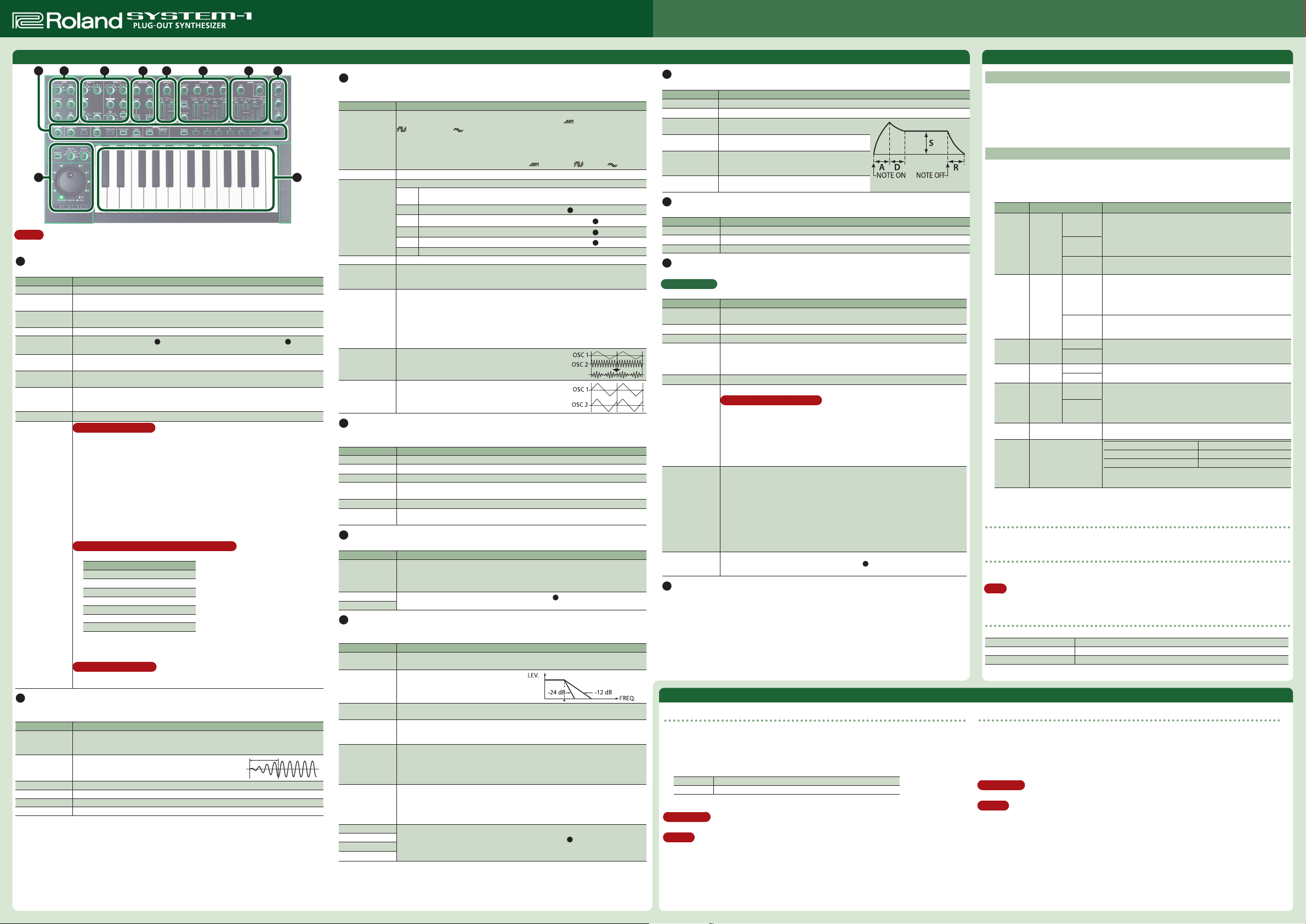
Panel Descriptions
2 3 4 5 6 7 81
9 10
MEMO
In this operation guide, functions added by installing the SYSTEM-1 update (ver. 1.10, ver. 1.11, ver. 1.12 and ver.
1.20) are printed in red.
1
Common section
Here you can make the following settings for the SYSTEM-1.
Controller Explanation
[VOLUME] knob Adjusts the volume.
[PORTAMENTO]
knob
[LEGATO] button
[TEMPO] knob Sets the tempo of the arpeggiator (scatter). The LED blinks at the tempo you specied.
[TEMPO SYNC]
button
[LFO KEY TRIG]
button
[MONO] button
MODEL
[SYSTEM-1]/[PLUGOUT] button
[MANUAL] button Causes sound to be produced according to the current settings of the knobs and sliders.
Memory[1]–[8]
button
2
LFO
Here you can create cyclic change (modulation) in the sound by applying vibrato (pitch modulation) or tremolo
(volume modulation).
Controller Explanation
Wave knob
[FADE TIME] knob
[RATE] knob Determines the speed of the LFO.
[PITCH] knob Allows the LFO to modulate the pitch, producing a vibrato eect.
[FILTER] knob Allows the LFO to modulate the FILTER CUTOFF (cuto frequency),
[AMP] knob Allows the LFO to modulate the AMP LEVEL (volume), producing a tremolo eect.
Creates a smooth change in pitch between one key and the next key played. The knob
adjusts the time required for the pitch change.
Applies portamento only when you play legato (i.e., when you press the next key before
releasing the previous key).
Synchronizes the RATE of the
section to the tempo.
Species whether the LFO cycle will be synchronized to begin when the key is pressed
(ON) or not (OFF).
If this is on (lit), the synth will play monophonically (single notes).
If this is blinking, the synth will play all sounds in unison (UNISON mode).
If the [SYSTEM-1] button is on, this unit will operate as a SYSTEM-1 synthesizer. If the
[PLUG-OUT] button is on, this unit will operate in “plug-out” mode.
What is “Memory/Bank”?
You can store/recall up to 64 sets (8 memories x 8 banks) of panel settings (knobs/sliders).
Switching banks
1. If you’re operating in SYSTEM-1 mode, long-press the [SYSTEM-1] button. If you’re
operating in PLUG-OUT mode, long-press the [PLUGOUT] button.
The memory button corresponding to the currently selected bank number blinks.
2. Press a memory [1]–[8] button to switch the bank.
* Even after you switch the bank, the sound prior to switching banks continues to be
heard until you press a memory button to switch sounds.
To store panel settings in a memory button
Long-press a memory [1]–[8] button.
To recall settings (a sound) from a memory button
Press a memory [1]–[8] button.
Additional settings that can be registered in memory
The settings of the following SCATTER controllers can now be registered in memory.
Controller
[ARPEGGIO] button
[ARP TYPE] knob
[ARP STEP] knob
[SCATTER] jog shuttle
[TYPE] dial
[KEY HOLD] button
OCTAVE [DOWN] [UP] buttons
With the settings of Ver. 1.20, the state of the above controllers is registered in memory.
If you don’t want the state of these controllers to be registered, refer to “MIDI and Other
Settings”–”Memory registration method (SCATTER controllers).”
Memory volume function
By holding down the [TEMPO SYNC] button and turning the [T YPE] dial, you can specify
the volume for each patch memory.
Selects the LFO waveform.
R (Sine wave), S (Triangle wave), T (Sawtooth wave), U (Square wave), W (Sample
and Hold), RND (Random wave)
Species the time from when the tone sounds until the LFO
reaches its maximum amplitude.
2
LFO section and the delay time (TIME) of the 8 EFFECTS
3
OSC 1/OSC 2
Here you can select the waveform that determines the character of the sound, and specify its pitch.
The SYSTEM-1 has two oscillators (OSC 1 and OSC 2).
Controller Explanation
Wave knob
[COLOR] knob The result depends on the waveform.
[MOD] knob
Octave (feet) knob Species the octave of the oscillator.
[CROSS MOD]
knob
[TUNE] knob
[RING] button
[SYNC] button
4
MIXER
Here you can adjust the volume of OSC 1, OSC 2, the sub-oscillator (an oscillator that produces a sound one or
two octaves lower), and noise.
Controller Explanation
[OSC 1] knob Adjusts the volume of the OSC 1.
[OSC 2] knob Adjusts the volume of the OSC 2.
[SUB OSC] knob Adjusts the volume of the sub oscillator.
[OSC TYPE] button
[NOISE] knob Adjusts the volume of the noise.
[NOISE TYPE]
button
5
PITCH
Here you can create time-varying change (envelope) for pitch.
Controller Explanation
[ENV] knob
[A] slider
[D] slider
6
FILTER
These settings determine the brightness and thickness of the sound. Here you can also specify the time-varying
change (envelope) for the lter.
Controller Explanation
[LPF CUTOFF] knob
[LPF TYPE] button
[HPF CUTOFF]
knob
[RESO] knob
[ENV] knob
[KEY] knob
[A] slider
[D] slider
[S] slider
[R] slider
Selects the waveform that is the basis of the sound.
T (Sawtooth wave), U (Square wave), S (Triangle wave),
(Square wave 2), (Triangle wave 2)
The newly added basic waveforms
To select the basic waveforms that were added, hold down the [LEGATO] button and turn
the OSC 1/OSC 2 waveform knob.
T (Noise Saw), U (Logic Operation), S (FM),
Selects the source that modulates the [COLOR] knob.
The sound is determined by the position of the [COLOR] knob. It will not vary over
MAN
time.
LFO
The sound varies over time at the rate specied in the
P. ENV
The sound changes over time according to the envelope of the
F. ENV
The sound changes over time according to the envelope of the
A. ENV
The sound changes over time according to the envelope of the
S. OSC The sound changes over time according to the frequency of the sub-oscillator.
Modies the OSC 1 frequency according to the OSC 2 waveform. Turning the knob toward
the right makes OSC 1 become a more complex sound, allowing you to create metallic
sounds or sound eects.
Adjusts the pitch of the oscillator.
Coarse Tune
Adjusts the pitch in semitone steps.
By holding down the [RING][SYNC] buttons simultaneously and turning the SCATTER
[TYPE] dial (or the OSC 2 [TUNE] k nob), you can adjust the Coarse Tune.
The SCATTER LEDs (1–10) indicate the amount of Coarse Tune (OFF (unlit), -11–+11). (LEDs
10 and 1 light simultaneously to indicate 11.)
This is a ring modulator. It generates a complex waveform
by multiplying OSC 1 and OSC 2.
This is oscillator sync. It generates a complex waveform
by forcibly resetting OSC 2 to the beginning of its cycle in
synchronization with the OSC 1 frequency.
Selects the type of the sub oscillator.
Lit: Sound one octave below, Unlit: Sound two octaves below
Selects the type of the noise.
Lit: white noise, Unlit: pink noise
If this knob is turned toward the right, the pitch initially becomes higher and then returns
to the pitch of the key you pressed.
If this knob is turned toward the left, the pitch initially becomes lower and then returns to
the pitch of the key you pressed.
These sliders operate similarly to the [A][D] sliders of the
pitch rather than the volume).
Species the cuto frequency of the low-pass lter. Frequency components above the
cuto frequency are cut, making the sound mellower.
Selects the slope (steepness) of the low-pass
lter.
Lit: -12 dB, Unlit: -24 dB
Species the cuto frequency of the high-pass lter. Frequency components below the
cuto frequency are cut.
Resonance boosts the sound in the region of the lter’s cuto frequency.
Higher settings produce stronger emphasis, creating a distinctively “synthesizer-like”
sound.
This knob species the depth and direction of the cuto frequency change produced by
the [A], [D], [S], and [R] sliders.
If the knob is turned toward the right, the cuto frequency moves in the upward direction.
If the knob is turned toward the left, the cuto frequency moves in the downward
direction.
Allows the lter cuto frequency to vary according to the key that you play.
If the knob is turned toward the right, the cuto frequency becomes higher as you play
higher notes.
If the knob is turned toward the left, the cuto frequency becomes lower as you play
lower notes.
These sliders operate similarly to the [A][D][S][R] sliders of the
the cuto frequency rather than the volume).
(FM + Sync), (Vowel), (CB)
(Sawtooth wave 2),
2
LFO section.
5
PITCH section.
6
FILTER section.
7
AMP section.
7
AMP section (they aect the
7
AMP section (they aect
7
AMP
Here you can create time-varying change (envelope) for the volume.
Controller Explanation
[TONE] knob Adjusts the brightness of the sound.
[CRUSHER] knob Modies the tonal character by distorting the waveform.
[A] slider
(Attack time)
[D] slider
(Decay time)
[S] slider
(Sustain level)
[R] slider
(Release time)
8
EFFECTS
Here you can adjust the amount of reverb and delay.
Controller Explanation
[REVERB] knob Adds reverberation.
[DELAY] knob Adjusts the volume of delay sound.
[TIME] knob Adjusts the delay time (the time by which the sound is delayed).
9
PITCH BEND/SCATTER
“Pitch bend” modies the pitch.
What is Scatter?
This is a function that applies various changes to the arpeggio performance, creating musical grooves.
Controller Explanation
[ARPEGGIO] button
[ARP TYPE] knob Selects the arpeggio variation.
[ARP STEP] knob Species the note value for each step of the arpeggiator.
[PITCH BEND/
SCATTER] jog
shuttle
[TYPE] dial Selects the scatter type (1–10).
[KEY HOLD] button
OCTAVE [DOWN]
[UP] button
[MOD] button
10
Keyboard
This is a standard-size keyboard.
It is not touch-sensitive (the velocity is xed).
Species the time from the moment you press the key
until the maximum volume is reached.
Species the time from when the maximum volume is
reached, until it decays to the sustain level.
Species the volume level that will be maintained
from when the attack and decay times have elapsed
until you release the key.
Species the time from when you release the key until
the volume reaches its minimum value.
Causes an arpeggio to be produced when you simply hold down a chord on the
keyboard. (This function is called the “arpeggiator.”)
The jog shuttle normally operates as pitch bend.
If the [ARPEGGIO] button is turned on, the jog shuttle adjusts the scatter depth.
* S catter is on while you operate the jog shuttle. When you return the jog shuttle to the
center, scatter turns o.
You can make notes continue sounding even after you take your hand o the keyboard.
Hold function for Scatter Depth
Now you can hold the Scatter Depth by pressing the [KEY HOLD] button.
Holding the Scatter Depth
1. Turn on the [ARPEGGIO] button to enable Scatter.
2. While operating the [SCATTER] jog shuttle, press the [KEY HOLD] button.
Cancelling the Hold function for Scatter Depth
Hold is cancelled when you once again operate the [SCATTER] jog shuttle.
Octave shift
You can shift the keyboard’s pitch range in steps of one octave. The button is lit for the
one octave setting; the button is blinking for the 2–3 octave setting. If you press the
[DOWN] [UP] buttons simultaneously, the keyboard will return to its normal pitch range.
Key transpose
By holding down the [DOWN][UP] buttons simultaneously and turning the SCATTER
[TYPE] dial, you can transpose the keyboard in semitone steps (only upward).
• The SCATTER LEDs (1–10) indicate the amount of transposition (1–11). (LEDs 10 and 1
light simultaneously to indicate 11.)
• All unlit (OFF) when turned to the far left
Vibrato (modulation) is applied to the sound while you hold down the [MOD] button. By
holding down the [MOD] button and operating the
MOD depth.
2
LFO section, you can adjust the
Data Backup/Restore
Backup
1. Hold down [ARPEGGIO] and switch on the power.
2. Connect your computer to the SYSTEM-1’s USB port via USB cable.
3. Open the “SYSTEM-1” drive folder on your computer.
The scene memory backup les are located in the “BACKUP” folder of the “SYSTEM-1” drive.
4. Copy the SYSTEM-1 Memory les in “BACKUP” folder into your computer.
SYSTEM-1 SYSTEM1_PATCH1.PRM - SYSTEM1_PATCH64.PRM
PLUGOUT PLUGOUT_PATCH1.PRM - PLUGOUT_PATCH64.PRM
5. After copying is completed, disconnect the USB cable.
Windows 8/7
Right-click on the “SYSTEM-1” icon in “My Computer” and execute “Eject.”
Mac OS
Drag the “SYSTEM-1” icon to the Trash icon in the Dock.
6. Turn the SYSTEM-1 power o.
Various Settings
Restoring the Factory Settings (Factory Reset)
Here’s how to return the SYSTEM-1 to its factory-set state.
1. While holding down the [MANUAL] button, turn on the power.
The [ARPEGGIO] button blinks.
If you decide to cancel the factory reset, turn o the power.
2. Press the [ARPEGGIO] button to execute the factory reset.
3. When all buttons lit, turn the SYSTEM-1’s power o, then on again.
MIDI and Other Settings
1. While holding down the [SYSTEM-1] button, turn on the power.
The [ARPEGGIO] button blinks.
If you decide not to make settings, turn o the power.
2. Use the following controllers to change the settings.
Parameter Controller Explanation
Unlit (OFF)
MIDI
Channel
MIDI Clock
Source
MIDI Thru [2] button
BOOST
Mode
Memory
registration
method
(SCATTER
controllers)
LED DEMO
Master
Tune
3. Press the [ARPEGGIO] button to save the settings.
The settings are saved, and the SYSTEM-1 restarts.
[TYPE] dial
1–16
All lit (OMNI)
Lit (AUTO)
[1] button
Unlit
(INTERNAL)
Lit (ON)
Unlit (OFF)
Lit (ON)
[3] button
Unlit (OFF)
Lit
(Registered)
[4] button
Unlit (Not
registered)
Hold down [MOD] and
turn the [TYPE] dial
Hold down [KEY HOLD]
and turn the jog shuttle
Take a snapshot of all controllers
Hold down the [MANUAL] button to transmit the current state of the knobs, sliders, and switches to a computer
or a MIDI device.
Change pitch bend range
Turn the [TYPE] dial while holding down the [LEGATO] button.
* The range is from 1 to 24.
e.g.)
The range is 12 when “10” and “2” are on.
The range is 24 when “10” blinks and “4” is on.
MIDI local on/o and MIDI controller mode
Turn the [TYPE] dial while holding down the [SYSTEM-1] button and the [PLUG-OUT] button.
LOCAL ON (“2” blinks) It produces sound through any operation including external MIDI message.
LOCAL OFF (“1” blinks) It produces sound only through external MIDI message.
MIDI CONTROLLER (“3” blinks) I t doesn’t produce sound through any operation, only outputs MIDI message.
Restore
1. Hold down [ARPEGGIO] and switch on the power.
2. Connect your computer to the SYSTEM-1’s USB port via USB cable.
3. Open the “SYSTEM-1” drive folder on your computer.
4. Copy the SYSTEM-1 memory les into the “RESTORE” folder.
5. After copying is completed, disconnect the USB cable.
Windows 8/7
Right-click on the “SYSTEM-1” icon in “My Computer” and execute “Eject.”
Mac OS
Drag the “SYSTEM-1” icon to the Trash icon in the Dock.
6. After the OCTAVE [DOWN][UP] buttons have completely stopped blinking, turn o the power.
Species the MIDI transmit/receive channel. The SCATTER LEDs
(1–10) indicate the channel. (default: 1)
• All unlit (OFF) when turned to the far left
• All lit (OMNI) when turned to the far right
• For 11–16, LEDs 10 and 1–6 are lit simultaneously.
MIDI messages of all channels are received.
The MIDI transmit channel will be 1.
If MIDI clock is being input to the MIDI IN connector or the USB port,
the SYSTEM-1’s tempo will automatically synchronize to MIDI clock.
(default)
* I f MIDI clock is being simultaneously input from the MIDI IN
connector and from the USB port, the USB port takes priority.
The SYSTEM-1 operates at the tempo specied on the unit itself.
Choose the “INTERNAL” setting if you don’t want to synchronize to
an external device.
Species whether data received from the MIDI IN connector will be
retransmitted from the MIDI OUT connector (ON: default) or will not
be retransmitted (OFF).
Boosts the output level of the OUT jacks.
Species whether the state of the SCATTER controllers is registered
in memory.
Species the time (minute) until the LED DEMO is shown. If this is
unlit, the LED DEMO is not shown.
OCTAVE [DOWN] [UP] buttons lit 440 Hz (default)
Only the [UP] button lit 440 + (SCATTER LED number) Hz
Only the [DOWN] button lit 440 - (SCATTER LED number) Hz
e.g.) If the [UP] button and the SCATTER LED (2) are lit, the setting
is 442 Hz.
01
 Loading...