

Roland S-0808 User Manual

Owner's Manual
Before using this unit, carefully read the sections entitled: “USING THE UNIT SAFELY” (Owner’s Manual
important information concerning the proper operation of the unit. Additionally, in order to feel
assured that you have gained a good grasp of every feature provided by your new unit, Owner’s
Manual should be read in its entirety. The manual should be saved and kept on hand as a convenient reference.
p. 4
), and “IMPORTANT NOTES” (Owner’s Manual
p. 6
). These sections provide
Copyright © 2010 ROLAND CORPORATION
All rights reserved. No part of this publication may be reproduced in any form without the written permis-
sion of ROLAND CORPORATION.

DECLARATION OF CONFORMITY
Compliance Information Statement
Model Name : S-0808
Type of Equipment : 8x8 I/O UNIT
Responsible Party : Roland Systems Group U.S.
Address : 801 West Orchard Drive, Suite 3, Bellingham, WA 98225
Telephone : (360) 594-4282
For the USA
Check the included items
The following items are included. Please make sure that all items are present. If anything is missing, please contact your dealer.
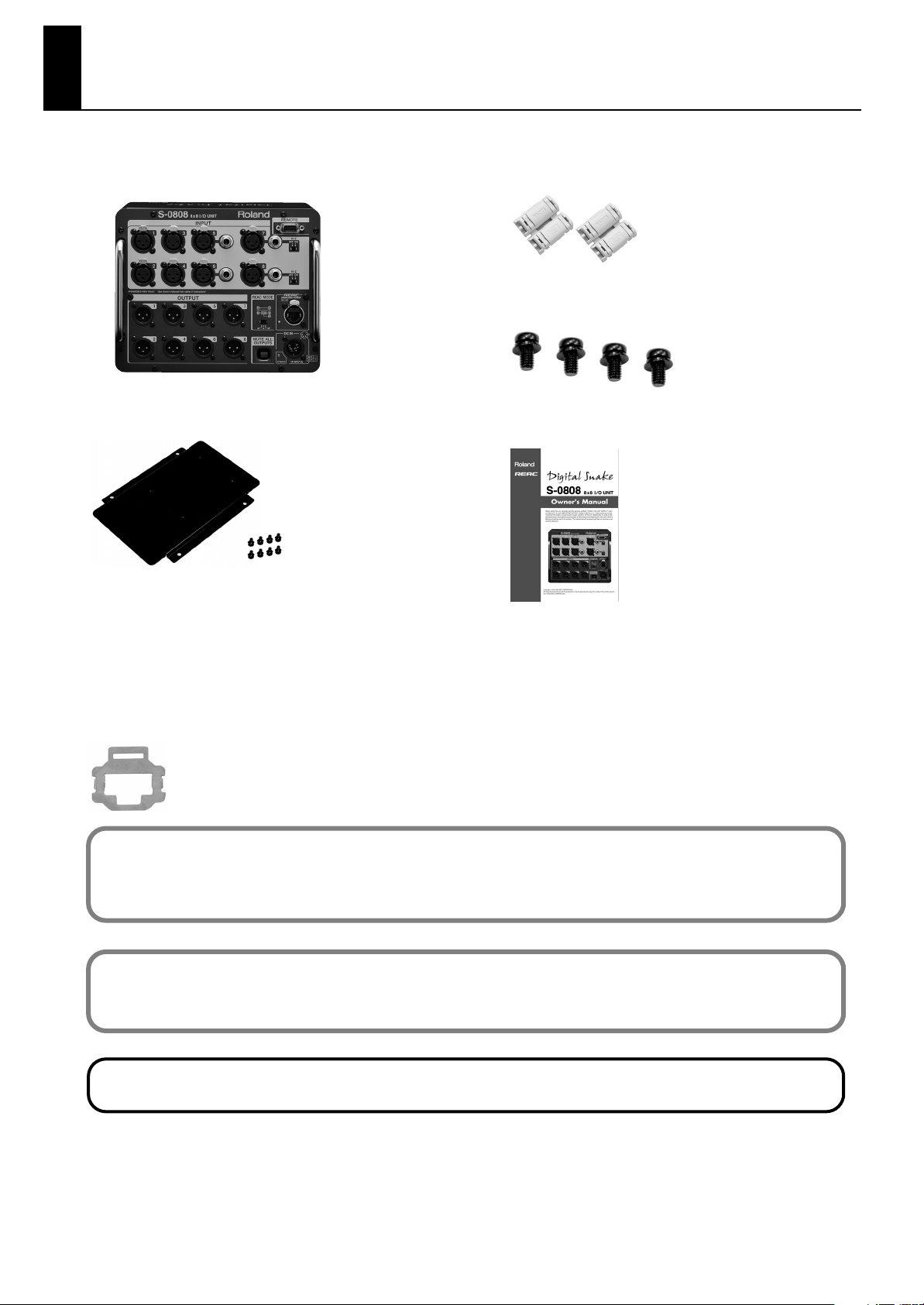
S-0808 itself
fig.S0808-itself.eps\
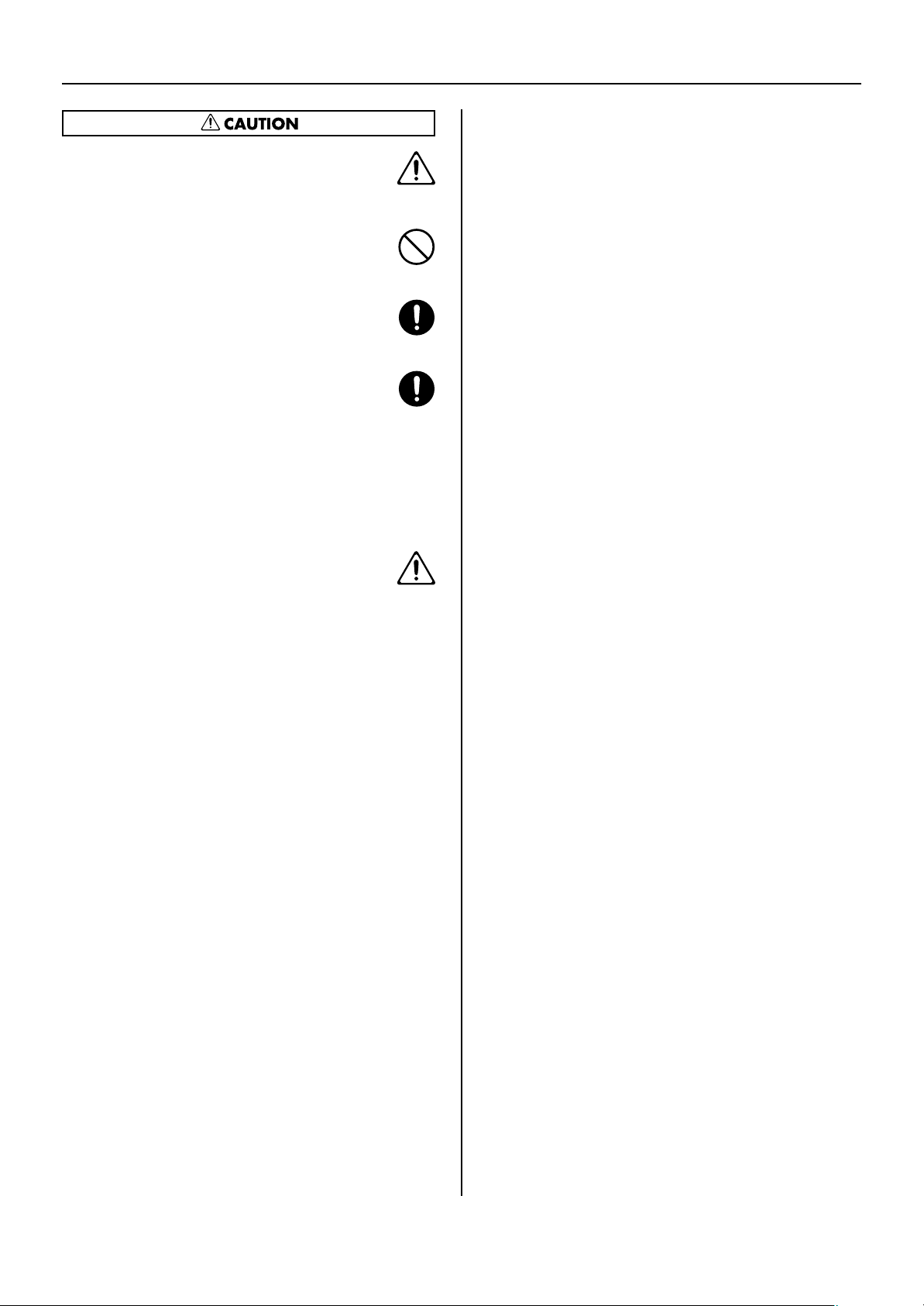
Battery plate holder and fastening screws (eight)
fig.bat-plate-holder.eps\
*Compatible with the P-V2 (V-Plate) made by the IDX Corporation
and with the QRC-GOLD made by Anton/Bauer, Inc.
*Four screws out of eight should be used to fasten the battery plate
holder to S-0808’s side panel. Remaining four screws should be
used to fasten battery plate (P-V2 or QRC-GOLD) to battery plate
holder.
Ferrite core (two)
fig.ferrite-core.eps\
Bottom panel fastening screws (four)
fig.four-screws.eps\
Owner’s manual (this document)
fig.owners-manual.eps\
REAC connector cover
fig.connector-cover.eps\
What’s REAC?
REAC (Roland Ethernet Audio Communication) is a proprietary audio-signal transmission protocol from Roland that is based on
Ethernet technology. It provides up to 40 channels of 24-bit, 96-kHz transmission of uncompressed audio signals. REAC devices are
connected using Cat 5e (Enhanced Category 5) Ethernet cable.
What’s REAC EMBEDDED POWER?
This is technology that supplies connected equipment with power while simultaneously transmitting REAC signals over the same
cable. This means the equipment receiving power does not need to be connected to a power cable or a battery.
MMP (Moore Microprocessor Portfolio) refers to a patent portfolio concerned with microprocessor architecture that was developed
by Technology Properties Limited (TPL). Roland has licensed this technology from the TPL Group.
* IDX and ENDURA are registered trademarks of IDX Company, Ltd.
* Anton Bauer is registered trademark of Anton/Bauser, Inc.
* Neutrik and EtherCon are registered trademarks of Neutrik , Inc.
* All product names mentioned in this document are trademarks or registered trademarks of their respective owners.
3
USING THE UNIT SAFELY
Used for instructions intended to alert
the user to the risk of death or severe
injury should the unit be used
improperly.
Used for instructions intended to alert
the user to the risk of injury or material
damage should the unit be used
improperly.
* Material damage refers to damage or
other adverse effects caused with
respect to the home and all its
furnishings, as well to domestic
animals or pets.
002a
Do not open or perform any internal modifica-
•
tions on the unit.
..........................................................................................................
003
Do not attempt to repair the unit, or replace parts
•
within it (except when this manual provides
specific instructions directing you to do so). Refer
all servicing to your retailer, the nearest Roland
Service Center, or an authorized Roland
distributor, as listed on the “Information” page.
..........................................................................................................
004
Never install the unit in any of the following
•
locations.
• Subject to temperature extremes (e.g., direct
sunlight in an enclosed vehicle, near a heating
duct, on top of heat-generating equipment); or
are
• Damp (e.g., baths, washrooms, on wet floors);
or are
• Exposed to steam or smoke; or are
• Subject to salt exposure; or are
• Humid; or are
• Exposed to rain; or are
• Dusty or sandy; or are
• Subject to high levels of vibration and
shakiness.
..........................................................................................................
007
Make sure you always have the unit placed so it is
•
level and sure to remain stable. Never place it on
stands that could wobble, or on inclined surfaces.
..........................................................................................................
The symbol alerts the user to important instructions
or warnings.The specific meaning of the symbol is
determined by the design contained within the
triangle. In the case of the symbol at left, it is used for
The symbol alerts the user to items that must never
be carried out (are forbidden). The specific thing that
must not be done is indicated by the design contained
within the circle. In the case of the symbol at left, it
means that the unit must never be disassembled.
The ● symbol alerts the user to things that must be
carried out. The specific thing that must be done is
indicated by the design contained within the circle. In
the case of the symbol at left, it means that the powercord plug must be unplugged from the outlet.
010
When used in combination with headphones,
•
amps or speakers, this device is capable of
producing volume levels that could cause
permanent hearing loss. Do not use this device at
high volumes for a extended period of time. If you
should experience any loss of hearing ringing in
the ears, you should immediately stop using the
unit, and consult a medical professional.
..........................................................................................................
011
•
Do not allow any objects (e.g., flammable
material, coins, pins); or liquids of any kind
(water, soft drinks, etc.) to penetrate the unit.
..........................................................................................................
012d
• Immediately turn the power off, and request
servicing by your retailer, the nearest Roland
Service Center, or an authorized Roland
distributor, as listed on the “Information” page
when:
• If smoke or unusual odor occurs
• Objects have fallen into, or liquid has been
spilled onto the unit; or
• The unit has been exposed to rain (or otherwise
has become wet); or
• The unit does not appear to operate normally
or exhibits a marked change in performance.
..........................................................................................................
013
When using this device in an environment where
•
children are present, an adult should provide
supervision until the child is capable of following
all the rules essential for the safe operation of the
unit.
..........................................................................................................
014
Protect the unit from strong impact.
•
(Do not drop it!)
..........................................................................................................
4
104
• Try to prevent cords and cables from becoming
entangled. Also, all cords and cables should be
placed so they are out of the reach of children.
..........................................................................................................
106
Never climb on top of, nor place heavy objects on
•
the unit.
..........................................................................................................
108c
Disconnect all cords coming from external devices
•
before moving the unit.
..........................................................................................................
118c
Keep small parts such as the following out of
•
reach of children so that they cannot be accidentally swallowed.
- Removed parts :
Grounding terminal screw
- Included items :
REAC connector covers, Ferrite core, Fastening
screws for battery plate holder,
Fastening screws for bottom panal.
..........................................................................................................
120
Always turn the phantom power off when
•
connecting any device other than condenser
microphones that require phantom power. You
risk causing damage if you mistakenly supply
phantom power to dynamic microphones, audio
playback devices, or other devices that don’t
require such power. Be sure to check the specifications of any microphone you intend to use by
referring to the manual that came with it.
USING THE UNIT SAFELY
(This unit’s phantom power: +48 V DC,
14 mA Max)
..........................................................................................................
5

IMPORTANT NOTES
Power Supply: Use of
Batteries
307
• Before connecting this unit to other devices, turn off the
power to all units. This will help prevent malfunctions
and/or damage to speakers or other devices.
Placement
351
• Using the unit near power amplifiers (or other equipment
containing large power transformers) may induce hum.
To alleviate the problem, change the orientation of this
unit; or move it farther away from the source of interference.
352a
• This device may interfere with radio and television
reception. Do not use this device in the vicinity of such
receivers.
352b
• Noise may be produced if wireless communications
devices, such as cell phones, are operated in the vicinity of
this unit. Such noise could occur when receiving or initiating a call, or while conversing. Should you experience
such problems, you should relocate such wireless devices
so they are at a greater distance from this unit, or switch
them off.
354a
• Do not expose the unit to direct sunlight, place it near
devices that radiate heat, leave it inside an enclosed
vehicle, or otherwise subject it to temperature extremes.
Excessive heat can deform or discolor the unit.
355b
• When moved from one location to another where the
temperature and/or humidity is very different, water
droplets (condensation) may form inside the unit. Damage
or malfunction may result if you attempt to use the unit in
this condition. Therefore, before using the unit, you must
allow it to stand for several hours, until the condensation
has completely evaporated.
360
• Depending on the material and temperature of the surface
on which you place the unit, its rubber feet may discolor
or mar the surface. You can place a piece of felt or cloth
under the rubber feet to prevent this from happening. If
you do so, please make sure that the unit will not slip or
move accidentally.
Repairs and Data
452
• Please be aware that all data contained in the unit’s
memory may be lost when the unit is sent for repairs.
Important data should always be written down on paper
(when possible). During repairs, due care is taken to avoid
the loss of data. However, in certain cases (such as when
circuitry related to memory itself is out of order), we
regret that it may not be possible to restore the data, and
Roland assumes no liability concerning such loss of data.
Additional Precautions
551
• Please be aware that the contents of memory can be
irretrievably lost as a result of a malfunction, or the
improper operation of the unit. To protect yourself against
the risk of loosing important data, we recommend that
you periodically write down the important data you
stored in the unit’s memory on paper..
552
• Unfortunately, it may be impossible to restore the
contents of data that was stored in the unit’s memory once
it has been lost. Roland Corporation assumes no liability
concerning such loss of data.
553
• Use a reasonable amount of care when using the unit’s
switch and when using its jacks and ports. Rough
handling can lead to malfunctions.
556
• When connecting / disconnecting all cables, grasp the
connector itself—never pull on the cable. This way you
will avoid causing shorts, or damage to the cable’s
internal elements.
558a
• To avoid disturbing your neighbors, try to keep the unit’s
volume at reasonable levels. You may prefer to use
headphones, so you do not need to be concerned about
those around you (especially when it is late at night).
559a
• When you need to transport the unit, package it in the box
(including padding) that it came in, if possible. Otherwise,
you will need to use equivalent packaging materials.
562
• Some connection cables contain resistors. Do not use
cables that incorporate resistors for connecting to this unit.
The use of such cables can cause the sound level to be
extremely low, or impossible to hear. For information on
cable specifications, contact the manufacturer of the cable.
Maintenance
401a
• For everyday cleaning wipe the unit with a soft, dry cloth
or one that has been slightly dampened with water. To
remove stubborn dirt, use a cloth impregnated with a
mild, non-abrasive detergent. Afterwards, be sure to wipe
the unit thoroughly with a soft, dry cloth.
402
• Never use benzine, thinners, alcohol or solvents of any
kind, to avoid the possibility of discoloration and/or
deformation.
6

Contents
Part Names and Functions .............................................................................8
About the Remote Controller ..................................................................... 10
Connecting Input and Output Devices ...................................................... 11
Connecting Input Devices .................................................................................................................................11
Connecting Amps and Speakers .....................................................................................................................12
Connecting REAC Devices ........................................................................... 13
Before Making REAC Connections..................................................................................................................13
Connecting S-0808 Units to One Another...................................................................................................14
Connecting to a REAC Splitter (S-4000D/S-4000-SP)...............................................................................15
Connecting to a REAC Merge Unit (S-4000M) ............................................................................................16
Connecting to an V-Mixer..................................................................................................................................17
Direct Connection to an V-Mixer..........................................................................................................................17
Connecting Via an S-4000D (Configuring an M-48 System) ......................................................................18
Turning the Power On and Off.................................................................... 19
Using REAC EMBEDDED POWER......................................................................................................................19
Using an External Battery...................................................................................................................................20
About External Batteries..........................................................................................................................................21
Setting the Input Channels ......................................................................... 22
Making Settings Using an S-4000R.................................................................................................................22
Adjusting the Preamp Gain....................................................................................................................................23
Switching the Gain Range (Pad)...........................................................................................................................24
Supplying Phantom Power ....................................................................................................................................24
Manipulating Two Channels As a Pair (Stereo Link)......................................................................................25
Making Settings Using S-4000 RCS.................................................................................................................26
Making Settings Using the V-Mixer................................................................................................................26
Appendices................................................................................................... 27
Troubleshooting....................................................................................................................................................27
Main Specifications ..............................................................................................................................................29
Operating Time with Battery ............................................................................................................................29
Connector Information.......................................................................................................................................30
Dimensions .............................................................................................................................................................31
Memo ............................................................................................................ 32
7
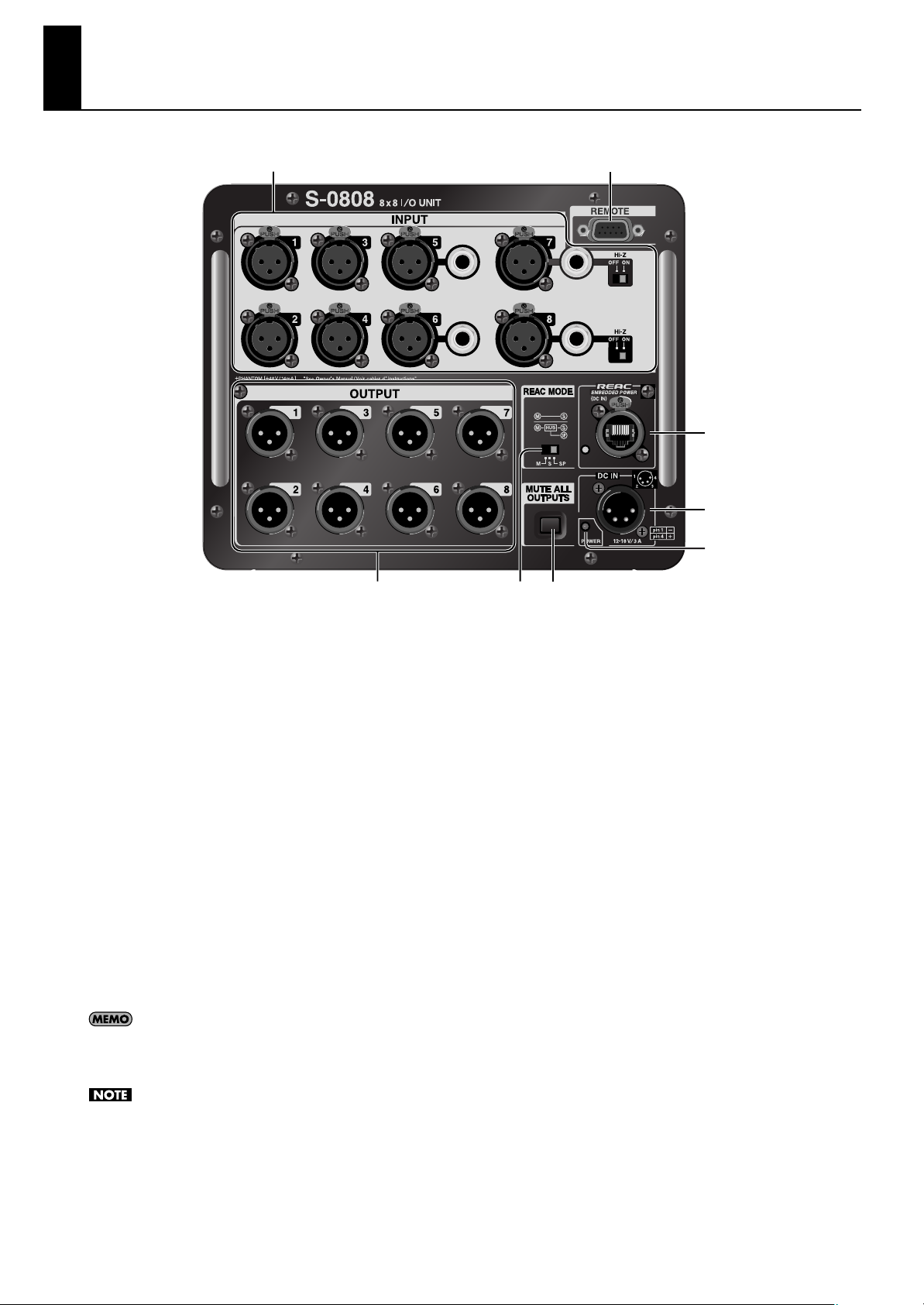
Part Names and Functions
fig.front-panel.eps
12
6
7
345
1. INPUT Connectors (p. 11)
Various input devices are connected to these. The inputs
include a variable-gain preamp that can accept signals from 65 through +10 dBu (nominal, maximum input: +28 dBu).
INPUT 1 - 4
These are balanced female XLR connectors.
INPUT 5/6
These are balanced female XLR connectors and standard TRS
connectors. When input is made to both simultaneously, the
TRS input takes priority.
INPUT 7/8
These are balanced female XLR connectors and standard TRS
connectors. When input is made to both simultaneously, the
TRS input takes priority.
The Hi-Z switch is set to ON when receiving input from an
electric guitar or other instrument with high-impedance
output.
You can adjust preamp gain and switch phantom power on
and off by remote control from an S-4000R unit or a computer
running the dedicated remote control software (S-4000 RCS).
Because setting the Hi-Z switch to ON makes the system more
susceptible to noise, take action to counter this, such as
keeping the connector cable short.
8
2. REMOTE Connector (p. 22)
This is a female 9-pin D-sub connector. It is used to connect a
dedicated remote controller for digital snake devices (the S4000R) or a computer installed with dedicated remotecontrol software (S-4000 RCS).
3. OUTPUT Connectors (p. 12)
These are balanced male XLR connectors. Amps and
powered speakers are connected here. The signal level that
is output is +4 dBu (nominal, maximum output: +22 dBu).
4. REAC MODE Switch (p. 14, p. 15, p. 16, p. 17)
This sets the S-0808’s operation mode. For the correct
operation of the system, the mode settings of REAC devices
must be made correctly. Making the wrong settings may
result in incorrect audio input and output.
• M The unit functions as a REAC master device.
• S The unit functions as a REAC slave device.
• SP The unit functions as a REAC split device.
5. MUTE ALL OUTPUTS Button
This mutes (silences) the system’s global audio output. When
the unit is muted, you can disconnect and connect input/
output or REAC cables without prooducing noise. When this
is pressed, all output is muted within a second or two.
Releasing the button cancels muting.
8
Part Names and Functions
6. REAC Port/Indicator (p. 13)
Connect REAC device here. The indicator lights up when communication with the connected REAC device is established. It flashes
during standby.
* The S-0808 can be powered via REAC EMBEDDED POWER. When an S-4000M, S-4000D, or other device that works as power source for REAC
EMBEDDED POWER is connected, the power source device automatically detects the S-0808 and starts to supply power through the REAC
cable. The S-0808 is designed to operate with this supplied power. An external battery is required when no power is received from a source
device providing REAC EMBEDDED POWER.
7. DC IN Port(p. 20)
This is for connecting an external battery. The unit requires an external battery when no power is received from REAC EMBEDDED
POWER or when an S-4000R, dedicated remote controller is connected.
* The unit is compatible with batteries used for broadcast video cameras (IDX or Anton/Bauer).
* Batteries for broadcast video-cameras have a feature for displaying the remaining charge. Make sure to check the remaining charge before
connecting.
8. POWER Indicator
This indicator lights up when the unit is receiving power from an external battery or a source device providing REAC EMBEDDED
POWER.
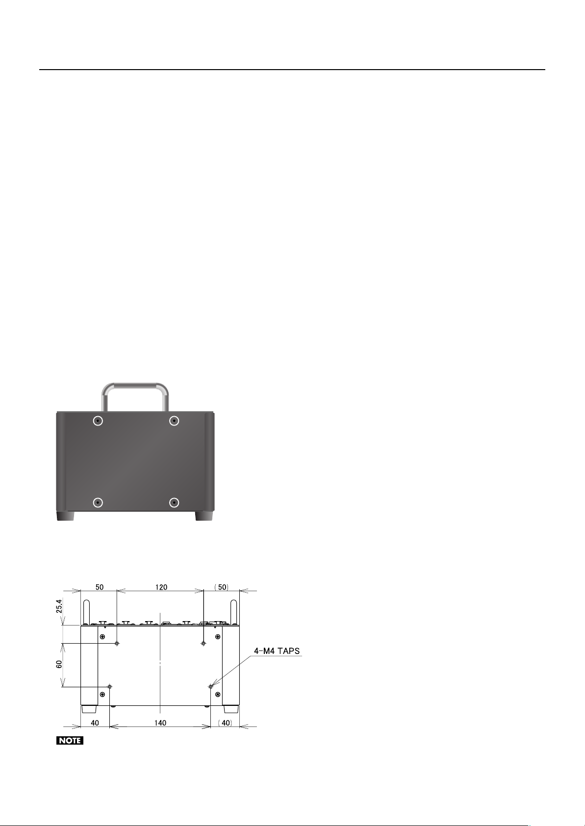
Holes for the Battery Plate Holder (p. 21)
These are used when attaching an external battery. Fasten the included battery plate holder to these holes using the four
dedicated screws that are also included.
fig.screw-holes.eps
About the Bottom Panel Mounting Screws
These are used when fastening S-0808 to a holder or the like. Fasten with the four included bottom panel mounting screws at the
screw holes shown below.
fig.bottom-screw-holes.eps
UNIT : mm
The screws for the battery plate holder and the screws for bottom panel fastening differ in diameter and length. Both types are dedicated screws.
Take care to avoid mixing them up.
9
About the Remote Controller
You can connect a dedicated remote controller for digital snake devices (the S-4000R) to the S-0808.
From the S-4000R, you can adjust preamp gain and switch phantom power on and off. The S-4000R supports control for up to 40
channels, but on an S-0808 system, it uses channels 1 through 16. The channels correspond to the preamps shown below.
• Channels 1 through 8: INPUT 1 through 8 on the S-0808 set to “REAC master”
• Channels 9 through 16: INPUT 1 through 8 on the S-0808 set to “REAC slave”
The S-0808 may not boot up correctly if the power supply from a REAC EMBEDDED POWER device is stared while S-4000R is connected to
S-0808’s REMOTE connector. Start your REAC EMBEDDED POWER device first to boot up the S-0808 and then connect an S-4000R,
or supply power from external battery.
When operating with REAC EMBEDDED POWER, the S-0808 power may turn off for a short moment if it supplies power to S-4000R and +48V
phantom power devices simultaneously. However, this is not a malfunction. The power of S-0808 does not turn off if it receives power from
external battery.
fig.S4000R.eps
1
10
2
3
11
12
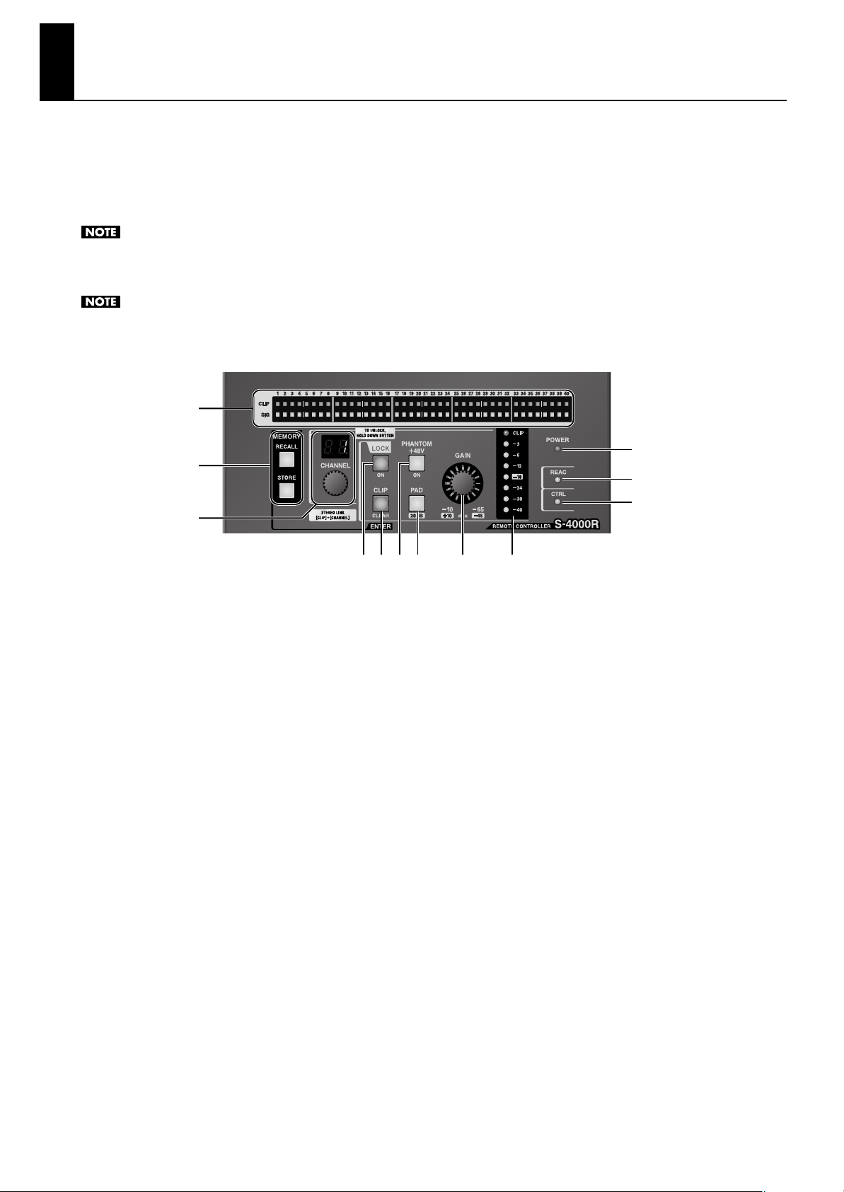
1. Signal Status Indicators
These indicate the status of signals input to the digital snake
devices.
CLIP Indicators
These light up when the input signal reaches 0 dB. Pressing
the [CLIP CLEAR/ENTER] button makes them go dark.
SIG Indicators
These light up when the input signal level exceeds -40 dB.
2. MEMORY Buttons
These are not used with connections to the S-0808.
3. CHANNEL Knob and Numerical Display
This selects the channel or level whose settings you want to
change or the channel you want to display. The numerical
display indicates the number of the currently selected
channel.
4. LOCK Button
This locks operation from the S-4000R. It lights up when
operation is locked. To unlock, hold down the button until its
light goes dark.
4 5 6 7 8 9
6. PHANTOM +48V Button
This supplies +48 V phantom power to the device connected
on the selected channel. It lights up when on and goes dark
when off.
7. PAD Button
This applies a -20 dB pad to the input level on the selected
channel.
8. GAIN Knob
This adjusts the input gain on the selected channel.
9. Input Level Meter
This displays the input level on the selected channel.
10. POWER Indicator
This lights up when power is supplied to the S-4000R via an
RS-232C cable.
11. REAC Indicator
This lights up when the connected S-0808 begins REAC
communication.
5. CLIP CLEAR / ENTER Button
This flashes when any of the CLIP indicators light up. Press
this when you want to make the indicators go dark.
10
12. CTRL Indicator
This lights up when communication is established between
the S-4000R and the S-0808.
Connecting Input and Output Devices
Feedback can be produced depending on the location of microphones relative to speakers. This can be remedied by:
1. Changing the orientation of the microphone(s).
2. Relocating microphone(s) at a greater distance from speakers.
3. Lowering volume levels.
* To prevent malfunctions and/or damages to speakers or other devices, always turn down the volume, and turn off the power on all devices
before making any connections.
* This unit is equipped with balanced (XLR/TRS) type jacks. Wiring diagrams for thse jacks are shown on “Connector Information“(p. 30). Make
connection after first checking the wiring diagram of other equipment you intend to connect.
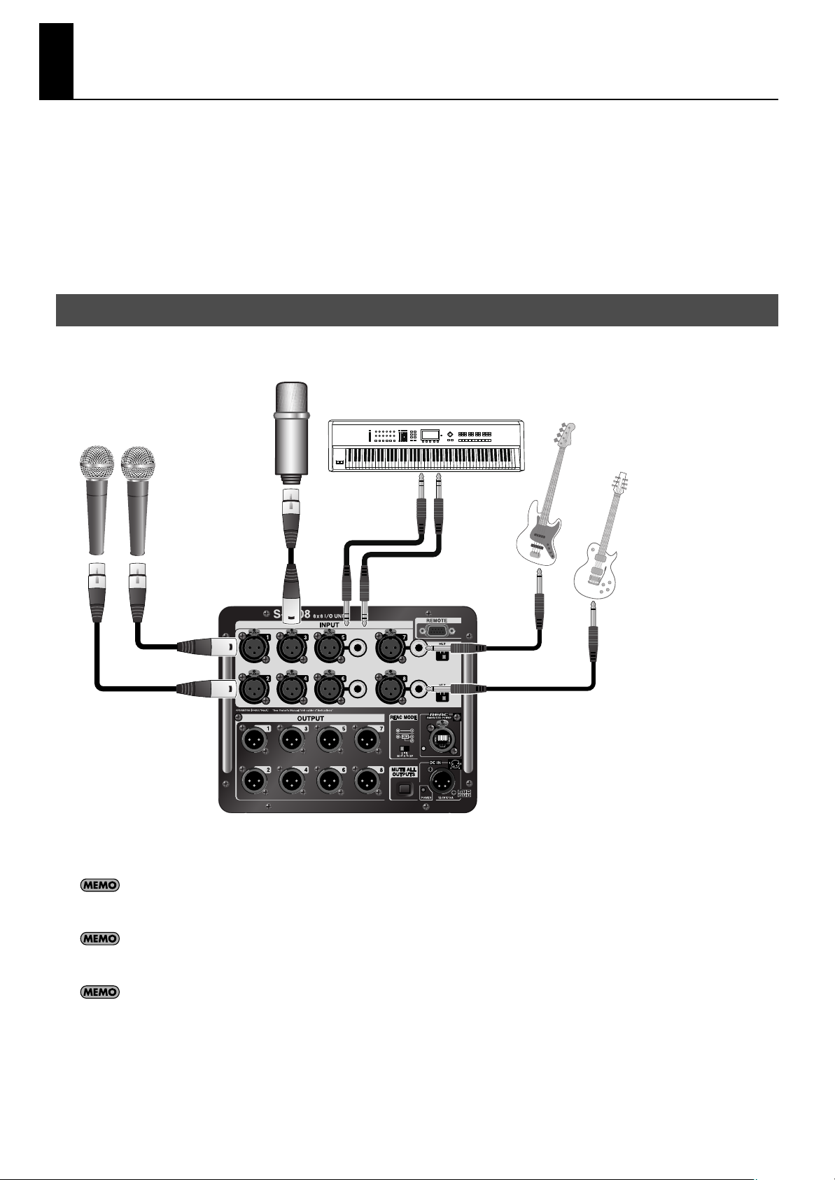
Connecting Input Devices
Connect input devices to INPUT 1 through 8. You can connect male XLR connectors to INPUT 1 through 8. Standard TRS
connectors are connected to INPUT 5 through 8.
fig.source-connection.eps
* When XLR and TRS connections are both made simultaneously to one of the connectors at INPUT 5 through 8, the TRS input takes priority.
* When connection cables with resistor are used, the volume level of equipment connected to the inputs (INPUT 1 through 8) may be low. If this
happens, use connection cables that do not contain resistors.
Connect electric guitars or other instruments with high-impedance output to INPUT 7 or 8. At this time, set the Hi-Z switch next to the INPUT
connector to ON. Setting the Hi-Z switch to ON makes INPUT 7/8 unbalanced.
You can supply +48 V phantom power from the XLR connectors at INPUT 1 through 8. When a condenser microphone or the like is connected
and supplying phantom power is required, switch it on by remote control. Refer to “Setting the Input Channel” (p. 22).
Preamp gain and phantom power on/off settings made by remote control remain in memory after the power to the S-0808 is switched off. You
can ensure that the settings are stored in memory by locking the remote control before switching off the power. If you’re using the S-4000R, press
the [LOCK] button to make it light up, wait several seconds, then power off the S-0808.
11
 Loading...