

Page 1
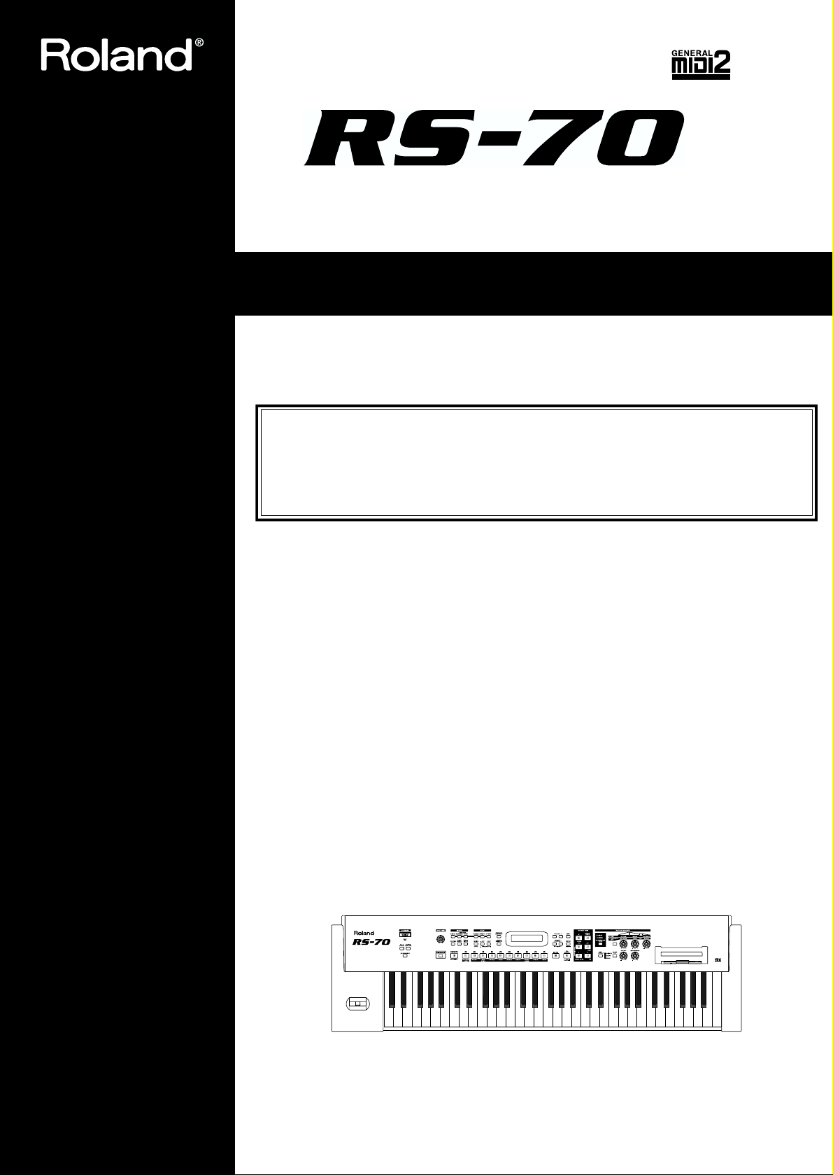
Owner’s Manual
Thank you, and congratulations on your choice of the Roland RS-70.
201a
Before using this unit, carefully read the sections entitled: “USING THE UNIT SAFELY”
(p. 2– 3) and “IMPORTANT NOTES” (p. 4–5). These sections provide important information concerning the proper operation of the unit. Additionally, in order to feel assured
that you have gained a good grasp of every feature provided by your new unit, Owner’s
manual should be read in its entirety. The manual should be saved and kept on hand as a
convenient reference.
202
Copyright © 2003 ROLAND CORPORATION
All rights reserved. No part of this publication may be reproduced in any form without
the written permission of ROLAND CORPORATION.
Page 2
USING THE UNIT SAFELY
IMPORTANT: THE WIRES IN THIS MAINS LEAD ARE COLOURED IN ACCORDANCE WITH THE FOLLOWING CODE.
For the U.K.
BLUE:
BROWN:
As the colours of the wires in the mains lead of this apparatus may not correspond with the coloured markings identifying
the terminals in your plug, proceed as follows:
The wire which is coloured BLUE must be connected to the terminal which is marked with the letter N or coloured BLACK.
The wire which is coloured BROWN must be connected to the terminal which is marked with the letter L or coloured RED.
Under no circumstances must either of the above wires be connected to the earth terminal of a three pin plug.
Used for instructions intended to alert
the user to the risk of death or severe
injury should the unit be used
improperly.
Used for instructions intended to alert
the user to the risk of injury or material
damage should the unit be used
improperly.
* Material damage refers to damage or
other adverse effects caused with
respect to the home and all its
furnishings, as well to domestic
animals or pets.
NEUTRAL
LIVE
The symbol alerts the user to important instructions
or warnings.The specific meaning of the symbol is
determined by the design contained within the
triangle. In the case of the symbol at left, it is used for
general cautions, warnings, or alerts to danger.
The symbol alerts the user to items that must never
be carried out (are forbidden). The specific thing that
must not be done is indicated by the design contained
within the circle. In the case of the symbol at left, it
means that the unit must never be disassembled.
The ● symbol alerts the user to things that must be
carried out. The specific thing that must be done is
indicated by the design contained within the circle. In
the case of the symbol at left, it means that the powercord plug must be unplugged from the outlet.
001
• Before using this unit, make sure to read the
instructions below, and the Owner’s Manual.
..........................................................................................................
002c
• Do not open (or modify in any way) the unit or its
AC adaptor.
..........................................................................................................
003
• Do not attempt to repair the unit, or replace parts
within it (except when this manual provides
specific instructions directing you to do so). Refer
all servicing to your retailer, the nearest Roland
Service Center, or an authorized Roland
distributor, as listed on the “Information” page.
..........................................................................................................
004
• Never use or store the unit in places that are:
• Subject to temperature extremes (e.g., direct
sunlight in an enclosed vehicle, near a heating
duct, on top of heat-generating equipment); or
are
• Damp (e.g., baths, washrooms, on wet floors);
or are
• Humid; or are
• Exposed to rain; or are
• Dusty; or are
• Subject to high levels of vibration.
..........................................................................................................
007
• Make sure you always have the unit placed so it is
level and sure to remain stable. Never place it on
stands that could wobble, or on inclined surfaces.
..........................................................................................................
008c
• Be sure to use only the AC adaptor supplied with
the unit. Also, make sure the line voltage at the
installation matches the input voltage specified on
the AC adaptor’s body. Other AC adaptors may
use a different polarity, or be designed for a
different voltage, so their use could result in
damage, malfunction, or electric shock.
..........................................................................................................
008e
• Use only the attached power-supply cord.
..........................................................................................................
009
• Do not excessively twist or bend the power cord,
nor place heavy objects on it. Doing so can
damage the cord, producing severed elements and
short circuits. Damaged cords are fire and shock
hazards!
..........................................................................................................
010
• This unit, either alone or in combination with an
amplifier and headphones or speakers, may be
capable of producing sound levels that could
cause permanent hearing loss. Do not operate for
a long period of time at a high volume level, or at
a level that is uncomfortable. If you experience
any hearing loss or ringing in the ears, you should
immediately stop using the unit, and consult an
audiologist.
..........................................................................................................
2
Page 3
011
• Do not allow any objects (e.g., flammable material,
coins, pins); or liquids of any kind (water, soft
drinks, etc.) to penetrate the unit.
..........................................................................................................
012b
• Immediately turn the power off, remove the AC
adaptor from the outlet, and request servicing by
your retailer, the nearest Roland Service Center, or
an authorized Roland distributor, as listed on the
“Information” page when:
• The AC adaptor, the power-supply cord, or the
plug has been damaged; or
• If smoke or unusual odor occurs
• Objects have fallen into, or liquid has been
spilled onto the unit; or
• The unit has been exposed to rain (or otherwise
has become wet); or
• The unit does not appear to operate normally or
exhibits a marked change in performance.
..........................................................................................................
013
• In households with small children, an adult
should provide supervision until the child is
capable of following all the rules essential for the
safe operation of the unit.
..........................................................................................................
014
• Protect the unit from strong impact.
(Do not drop it!)
..........................................................................................................
015
• Do not force the unit’s power-supply cord to share
an outlet with an unreasonable number of other
devices. Be especially careful when using
extension cords—the total power used by all
devices you have connected to the extension
cord’s outlet must never exceed the power rating
(watts/amperes) for the extension cord. Excessive
loads can cause the insulation on the cord to heat
up and eventually melt through.
..........................................................................................................
016
• Before using the unit in a foreign country, consult
with your retailer, the nearest Roland Service
Center, or an authorized Roland distributor, as
listed on the “Information” page.
..........................................................................................................
023
• DO NOT play a CD-ROM disc on a conventional
audio CD player. The resulting sound may be of a
level that could cause permanent hearing loss.
Damage to speakers or other system components
may result.
..........................................................................................................
101b
• The unit and the AC adaptor should be located so
their location or position does not interfere with
their proper ventilation.
..........................................................................................................
102c
• Always grasp only the plug on the AC adaptor
cord when plugging into, or unplugging from, an
outlet or this unit.
..........................................................................................................
103b
• Any accumulation of dust between the AC
adaptor and the power outlet can result in poor
insulation and lead to fire. Periodically wipe away
such dust with a dry cloth. Also, disconnect the
power plug from the power outlet whenever the
unit is to remain unused for an extended period of
time.
..........................................................................................................
104
• Try to prevent cords and cables from becoming
entangled. Also, all cords and cables should be
placed so they are out of the reach of children.
..........................................................................................................
106
• Never climb on top of, nor place heavy objects on
the unit.
..........................................................................................................
107c
• Never handle the AC adaptor or its plugs with
wet hands when plugging into, or unplugging
from, an outlet or this unit.
..........................................................................................................
108b
• Before moving the unit, disconnect the AC
adaptor and all cords coming from external
devices.
..........................................................................................................
109b
• Before cleaning the unit, turn off the power and
unplug the AC adaptor from the outlet (p. 19).
..........................................................................................................
110b
• Whenever you suspect the possibility of lightning
in your area, disconnect the AC adaptor from the
outlet.
..........................................................................................................
118
• Should you remove the ground terminal screw,
make sure to put it in a safe place out of children's
reach, so there is no chance of them being
swallowed accidentally.
..........................................................................................................
3
Page 4

IMPORTANT NOTES
291a
In addition to the items listed under “USING THE UNIT SAFELY” on page 2–3, please read and observe the following:
Power Supply
301
• Do not use this unit on the same power circuit with any
device that will generate line noise (such as an electric
motor or variable lighting system).
302
• The AC adaptor will begin to generate heat after long
hours of consecutive use. This is normal, and is not a
cause for concern.
307
• Before connecting this unit to other devices, turn off the
power to all units. This will help prevent malfunctions
and/or damage to speakers or other devices.
Placement
351
• Using the unit near power amplifiers (or other equipment
containing large power transformers) may induce hum.
To alleviate the problem, change the orientation of this
unit; or move it farther away from the source of interference.
352a
• This device may interfere with radio and television
reception. Do not use this device in the vicinity of such
receivers.
352b
• Noise may be produced if wireless communications
devices, such as cell phones, are operated in the vicinity of
this unit. Such noise could occur when receiving or initiating a call, or while conversing. Should you experience
such problems, you should relocate such wireless devices
so they are at a greater distance from this unit, or switch
them off.
353
• Observe the following when using the unit’s floppy disk
drive. For further details, refer to “Before Using Floppy
Disks” (p. 5).
• Do not place the unit near devices that produce a
strong magnetic field (e.g., loudspeakers).
• Install the unit on a solid, level surface.
• Do not move the unit or subject it to vibration while
the drive is operating.
354a
• Do not expose the unit to direct sunlight, place it near
devices that radiate heat, leave it inside an enclosed
vehicle, or otherwise subject it to temperature extremes.
Excessive heat can deform or discolor the unit.
355b
• When moved from one location to another where the
temperature and/or humidity is very different, water
droplets (condensation) may form inside the unit. Damage
or malfunction may result if you attempt to use the unit in
this condition. Therefore, before using the unit, you must
allow it to stand for several hours, until the condensation
has completely evaporated.
358
• Do not allow objects to remain on top of the keyboard.
This can be the cause of malfunction, such as keys ceasing
to produce sound.
Maintenance
401a
• For everyday cleaning wipe the unit with a soft, dry cloth
or one that has been slightly dampened with water. To
remove stubborn dirt, use a cloth impregnated with a
mild, non-abrasive detergent. Afterwards, be sure to wipe
the unit thoroughly with a soft, dry cloth.
402
• Never use benzine, thinners, alcohol or solvents of any
kind, to avoid the possibility of discoloration and/or
deformation.
Additional Precautions
•
Never turn off the power while the display indicates “KEEP
POWER ON!” If you turn off the power while this message is
displayed, all of the internal user data will be lost.
551
• Please be aware that the contents of memory can be
irretrievably lost as a result of a malfunction, or the
improper operation of the unit. To protect yourself against
the risk of loosing important data, we recommend that
you periodically save a backup copy of important data
you have stored in the unit’s memory on a floppy disk, or
other devices.
552
• Unfortunately, it may be impossible to restore the contents
of data that was stored on a floppy disk, or in the unit’s
memory once it has been lost. Roland Corporation
assumes no liability concerning such loss of data.
553
• Use a reasonable amount of care when using the unit’s
buttons, sliders, or other controls; and when using its jacks
and connectors. Rough handling can lead to malfunctions.
554
• Never strike or apply strong pressure to the display.
556
• When connecting / disconnecting all cables, grasp the
connector itself—never pull on the cable. This way you
will avoid causing shorts, or damage to the cable’s
internal elements.
558a
• To avoid disturbing your neighbors, try to keep the unit’s
volume at reasonable levels. You may prefer to use
headphones, so you do not need to be concerned about
those around you (especially when it is late at night).
559a
• When you need to transport the unit, package it in the box
(including padding) that it came in, if possible. Otherwise,
you will need to use equivalent packaging materials.
561
• Use only the specified expression pedal (EV-5; sold
separately). By connecting any other expression pedals,
you risk causing malfunction and/or damage to the unit.
985
• The explanations in this manual include illustrations that
depict what should typically be shown by the display.
Note, however, that your unit may incorporate a newer,
enhanced version of the system (e.g., includes newer
sounds), so what you actually see in the display may not
always match what appears in the manual.
4
Page 5

Before Using Floppy Disks
Handling the Floppy Disk Drive
602
• Install the unit on a solid, level surface in an area free from
vibration. If the unit must be installed at an angle, be sure
the installation does not exceed the permissible range:
upward, 2°; downward, 18°.
603
• Avoid using the unit immediately after it has been moved
to a location with a level of humidity that is greatly
different than its former location. Rapid changes in the
environment can cause condensation to form inside the
drive, which will adversely affect the operation of the
drive and/or damage floppy disks. When the unit has
been moved, allow it to become accustomed to the new
environment (allow a few hours) before operating it.
604
• To insert a disk, push it gently but firmly into the drive—
it will click into place. To remove a disk, press the EJECT
button firmly. Do not use excessive force to remove a disk
which is lodged in the drive.
605a
• Never attempt to remove a floppy disk from the drive
while the drive is operating (the indicator is lit); damage
could result to both the disk and the drive.
606
• Remove any disk from the drive before powering up or
down.
607
• To prevent damage to the disk drive’s heads, always try to
hold the floppy disk in a level position (not tilted in any
direction) while inserting it into the drive. Push it in
firmly, but gently. Never use excessive force.
608
• To avoid the risk of malfunction and/or damage, insert
only floppy disks into the disk drive. Never insert any
other type of disk. Avoid getting paper clips, coins, or any
other foreign objects inside the drive.
653
• The identification label should be firmly affixed to the
disk. Should the label come loose while the disk is in the
drive, it may be difficult to remove the disk.
654
• Store all disks in a safe place to avoid damaging them, and
to protect them from dust, dirt, and other hazards. By
using a dirty or dust-ridden disk, you risk damaging the
disk, as well as causing the disk drive to malfunction.
Handling CD-ROMs
563
• Unauthorized duplication, reproduction, hiring, and
lending of the software included in the applied CD-ROM
is prohibited.
801
• Avoid touching or scratching the shiny underside
(encoded surface) of the disc. Damaged or dirty CD-ROM
discs may not be read properly. Keep your discs clean
using a commercially available CD cleaner.
Handling Floppy Disks
651
• Floppy disks contain a plastic disk with a thin coating of
magnetic storage medium. Microscopic precision is
required to enable storage of large amounts of data on
such a small surface area. To preserve their integrity,
please observe the following when handling floppy disks:
• Never touch the magnetic medium inside the disk.
• Do not use or store floppy disks in dirty or dusty areas.
• Do not subject floppy disks to temperature extremes
(e.g., direct sunlight in an enclosed vehicle). Recommended temperature range: 0 to 50° C (50 to 122° F).
• Do not expose floppy disks to strong magnetic fields,
such as those generated by loudspeakers.
652
•
Floppy disks have a “write protect” tab which can protect
the disk from accidental erasure. It is recommended that
the tab be kept in the PROTECT position, and moved to
the WRITE position only when you wish to write new
data onto the disk.
Rear side of the disk
Write
(can write new data onto disk)
Write Protect Tab
Protect
(prevents writing to disk)
204
* Microsoft and Windows are registered trademarks of
Microsoft Corporation.
206f
* Windows® 2000 is known officially as: “Microsoft®
Windows® 2000 operating system.”
206g
* Windows® Me is known officially as: “Microsoft®
Windows® Millennium Edition operating system.”
206h
* Windows® XP is known officially as: “Microsoft®
Windows® XP operating system.”
206e
* Screen shots in this documents are reprinted with
permission from Microsoft Corporation.
207
* Apple and Macintosh are registered trademark of Apple
Computer, Inc.
209
* MacOS is a trademark of Apple Computer, Inc.
220
* All product names mentioned in this document are trade-
marks or registered trademarks of their respective owners.
5
Page 6

Contents
IMPORTANT NOTES ...............................................................................4
Main Features........................................................................................11
Panel descriptions ................................................................................12
Front panel................................................................................................................................................. 12
Rear panel.................................................................................................................................................. 16
Getting ready.........................................................................................17
Connecting the RS-70 to external equipment....................................................................................... 17
Turning on/off the power....................................................................................................................... 18
Adjusting the display contrast (LCD CONTRAST) ............................................................................ 19
Reset to default factory settings (Factory Reset) ..............................20
Listening to the demo songs ...............................................................21
Demo songs list......................................................................................................................................... 21
Quick Start ...................................23
Try out the sounds................................................................................24
Selecting a patch .......................................................................................................................................24
Selecting a patch by category ......................................................................................................24
Selecting patches while listening to phrases (Patch Audition) .............................................. 26
Selecting a rhythm set.............................................................................................................................. 26
Playing arpeggios (Phrase/Arpeggio) .................................................................................................. 27
Changing the way in which the arpeggios are sounded......................................................... 27
Playing a chord at the touch of a finger (Multi-chord Memory)....................................................... 28
Switching chord sets..................................................................................................................... 29
Applying various effects to the sound................................................30
Changing the tone with the knobs (Patch Modify) .............................................................................30
Selecting the tone that you want to modify (DESTINATION TONE) .................................. 30
Adjusting the volume balance of the two tones .......................................................................30
Vibrato and Wah effects (LFO) ...................................................................................................31
Changing the sound’s volume (ENVELOPE) ........................................................................... 32
Changing the brightness of the sound and adding special qualities (CUTOFF/RESONANCE)
Using a lever to modify the sound......................................................................................................... 33
Changing the sound’s pitch in real time (Pitch Bend Lever).................................................. 33
Adding a vibrato effect to the sound (Modulation Lever)...................................................... 33
Using a pedal to modify the sound........................................................................................................ 34
Shifting the keyboard range in one-octave steps (Octave Shift)........................................................ 34
Moving the key range in half-steps (TRANSPOSE)............................................................................ 35
Waving your hand over the D Beam (D Beam Controller) ................................................................ 35
Effects that can be used with the D Beam controller ...............................................................36
Adjusting the sensitivity of the D Beam controllers (D BEAM SENS).................................. 38
Changing the polarity of the change (D BEAM POLARITY) ................................................. 38
Using the RS-70 effects............................................................................................................................. 39
Turning effects on and off (Master Effects Switch).................................................................. 39
...... 33
Using the sequencer to create a pattern ............................................40
Creating a new pattern based on a preset rhythm pattern ................................................................ 40
Creating a pattern from scratch (Pattern Initialize)............................................................................. 46
Editing a recorded pattern ...................................................................................................................... 46
Playing along with SMF data (SMF Player mode) ..............................47
6
Page 7

Contents
Advanced Use .............................. 49
Overview of the RS-70 ..........................................................................50
How the instrument is organized ..........................................................................................................50
Basic structure................................................................................................................................ 50
Classification of RS-70 sound types....................................................................................................... 50
Effects ......................................................................................................................................................... 51
Sequencer................................................................................................................................................... 51
Number of voices ..................................................................................................................................... 51
About memory.......................................................................................................................................... 52
Temporary memory...................................................................................................................... 52
Rewritable memory ...................................................................................................................... 52
Non-rewritable memory ..............................................................................................................52
Basic operation of the RS-70 ...............................................................53
Switching the mode.................................................................................................................................. 53
Patch mode..................................................................................................................................... 53
Pattern mode.................................................................................................................................. 53
Song mode...................................................................................................................................... 53
SMF Player mode .......................................................................................................................... 53
Editing parameters................................................................................................................................... 53
Basic procedure .............................................................................................................................53
Executing a command .................................................................................................................. 53
Assigning a name.......................................................................................................................... 54
When one page contains two or more settings......................................................................... 54
Inputting numbers and numerals .......................................................................................................... 54
Selecting a part.......................................................................................................................................... 54
Creating a patch (Patch mode) ............................................................55
How to make the patch settings............................................................................................................. 55
Changing the way that the tones are sounded (Key Mode) ................................................... 55
Editing the patch parameters ......................................................................................................55
Making settings that apply to the entire patch (Patch Common parameters) ..................... 56
Making settings for an individual tone (Patch Tone parameters) .........................................57
Saving a patch ........................................................................................................................................... 59
Convenient functions for patch editing (Patch Utility)....................................................................... 60
Copying patch parameters (PATCH PRM COPY)................................................................... 60
Initializing the parameters of a patch (PATCH INITIALIZE)................................................ 61
Erasing a user patch you saved (PATCH REMOVE) .............................................................. 61
Transmitting patch/rhythm settings from the MIDI OUT connector (XFER to MIDI)
Restoring the factory settings (FACTORY RESET) .................................................................. 62
..................... 62
Creating a rhythm set (Patch mode) ...................................................63
How to make the rhythm set settings.................................................................................................... 63
Editing the rhythm set parameters............................................................................................. 63
Making settings that apply to the entire rhythm set (Rhythm Common parameters) ....... 63
Editing the settings of each rhythm tone (key) (Rhythm Tone parameters)........................ 63
Saving a rhythm set (User Rhythm Set)................................................................................................ 64
Convenient functions for rhythm set editing (Rhythm Set Utility) ..................................................64
Copying effect settings from a rhythm set (RHY PRM COPY).............................................. 64
Initializing the settings of a specific rhythm tone (RHY INITIALIZE) ................................. 65
Erasing a rhythm set you saved (RHY REMOVE) ................................................................... 65
7
Page 8

Contents
Using the sequencer to create patterns (Pattern mode) ...................66
Playing patterns........................................................................................................................................ 66
Selecting a pattern to play back .................................................................................................. 66
Selecting pattern numbers ........................................................................................................... 66
Switching patterns during playback .......................................................................................... 66
Muting a part (Track Mute) ......................................................................................................... 67
Selecting a sound (patch) for each part...................................................................................... 67
Set the pattern tempo.................................................................................................................... 67
Recording your performance while you play it (Realtime recording) .............................................67
Recording .......................................................................................................................................67
Undo/redo the previous recording operation.......................................................................... 70
Various settings for realtime recording ..................................................................................... 70
Recording with the phrase/arpeggio function......................................................................... 72
Creating your own arpeggio template (User Template) ......................................................... 72
Using chord memory to record................................................................................................... 74
Creating an original chord set (User Chord Set) ......................................................................74
Recording notes one at a time (Step Recording)..................................................................................75
Inputting various types of notes ................................................................................................. 76
Editing individual items of music data (Microscope edit)................................................................. 76
Music data handled in Microscope mode ................................................................................. 76
Editing the music data.................................................................................................................. 77
Selecting the types of music data for viewing (View Filter)................................................... 78
Microscope Utility .................................................................................................................................... 78
Inserting music data (INS)........................................................................................................... 78
Deleting music data (DEL)........................................................................................................... 78
Moving music data (MOVE) ....................................................................................................... 78
Copying music data (COPY) .......................................................................................................78
Pasting music data (PASTE)........................................................................................................ 78
Editing the settings of a pattern .............................................................................................................79
Making settings that apply to the entire pattern ...................................................................... 79
Editing the effect settings of a pattern ....................................................................................... 80
Editing the part settings of a pattern (Part Setup).................................................................... 80
Editing the effect settings for each part of the pattern (Pattern Part Effect)......................... 82
Saving a pattern ........................................................................................................................................ 82
Convenient functions for pattern editing (Pattern Utility) ................................................................ 83
Erasing unwanted performance data (PTN ERASE) ............................................................... 83
Deleting unwanted measures (PTN DELETE).......................................................................... 84
Correcting the timing of a pattern (PTN QUANTIZE)............................................................ 84
Copying a pattern (PTN COPY).................................................................................................. 84
Inserting blank measures (PTN INSERT).................................................................................. 85
Transposing the pitch (PTN TRANSPOSE) .............................................................................. 85
Modifying the velocity of notes (PTN CHG VEL) ................................................................... 86
Modifying the note length (PTN CHG GT)............................................................................... 86
Shifting pattern data forward and back (PTN SHIFT CLK) ................................................... 87
Thinning out unneeded data (PTN DATA THIN)................................................................... 87
Initializing the parameters of a pattern (PTN INIT) ................................................................ 88
Creating your own user arpeggio style (PTNÆARP CONV) ................................................ 88
Copying parameters from a pattern (PTN PRM COPY) ......................................................... 89
Transmitting pattern settings from the MIDI OUT connector (XFER to MIDI)................... 90
Restoring the factory settings (FACTORY RESET) .................................................................. 90
Adding effects .......................................................................................91
Turning the effect function on and off (MASTER EFFECT SWITCH) ............................................. 91
The effect signal path ............................................................................................................................... 92
Making effects settings ............................................................................................................................93
Setting multi-effects parameters............................................................................................................. 94
Making chorus settings.......................................................................................................................... 112
Making reverb settings .......................................................................................................................... 113
How effects will switch while a pattern is playing................................................................ 113
8
Page 9

Contents
Connecting patterns to create a song (Song mode) .......................114
Playing back a song................................................................................................................................ 114
Selecting a song to play back..................................................................................................... 114
Muting a part (Track Mute) ....................................................................................................... 114
Set the song tempo...................................................................................................................... 115
Creating a song ....................................................................................................................................... 115
Saving a song .......................................................................................................................................... 115
Editing song settings.............................................................................................................................. 116
Editing the song name................................................................................................................ 116
Looping the song......................................................................................................................... 116
Convenient functions for song editing (Song Utility)....................................................................... 116
Deleting an unwanted step (SONG STEP DELETE).............................................................. 116
Inserting a step (SONG STEP INSERT) ................................................................................... 116
Copying a song (SONG COPY) ................................................................................................ 117
Initializing the parameters of a song (SONG INIT) ............................................................... 117
Erasing a user song you saved (SONG REMOVE) ................................................................118
Restoring the factory settings (FACTORY RESET) ................................................................ 118
Using the floppy disk drive ................................................................119
Playing back an SMF file ....................................................................................................................... 119
Disk-related functions (Disk Utility) ...................................................................................................119
Loading a file from disk into the RS-70 (LOAD) .................................................................... 119
Saving data on disk (SAVE)....................................................................................................... 120
Preparing a disk for use by the RS-70 (FORMAT) ................................................................. 121
Creating a duplicate disk (BACKUP)....................................................................................... 122
Modifying the name of the disk (VOLUME LABEL)............................................................. 122
Deleting unwanted files (DELETE) .......................................................................................... 122
Renaming a file (RENAME) ...................................................................................................... 123
Checking the remaining space of the disk (DISK INFO)....................................................... 123
Settings common to all modes (System Function) .........................124
How to make the system function settings......................................................................................... 124
Functions of the system parameters .................................................................................................... 125
Settings common to the entire system (GENERAL) ..............................................................125
Settings related to the metronome (METRONOME)............................................................. 125
Settings related to controllers (CONTROLLER)..................................................................... 126
Settings related to MIDI and USB (MIDI&USB)..................................................................... 127
Checking memory usage status (MEMORY INFO) ............................................................... 128
Making scale tune settings for a patch (PATCH SCALE) ..................................................... 128
Performing with an external MIDI device..........................................129
About MIDI ............................................................................................................................................. 129
MIDI messages used by the RS-70 ....................................................................................................... 129
Using the RS-70 to play an external MIDI sound module................................................................ 130
Connecting to external MIDI sound modules ........................................................................ 130
Set the keyboard transmit channel ........................................................................................... 131
Playing the RS-70’s sound generator from an external MIDI device.............................................. 131
Connecting an external MIDI device........................................................................................ 131
Setting the patch receive channel.............................................................................................. 132
Setting the program change receive switch............................................................................. 132
Selecting RS-70 sounds from an external MIDI device.......................................................... 132
Using an external MIDI controller to change the RS-70’s tones........................................... 133
Recording to an external sequencer..................................................................................................... 133
Connecting to an external sequencer .......................................................................................133
Making settings before recording............................................................................................. 133
Recording .....................................................................................................................................134
Listening to the recorded performance.................................................................................... 134
Playing together with the playback of a recorded performance.......................................... 135
Transposing playback of performances (Master Key Shift).................................................. 135
9
Page 10

Contents
Using the RS-70 as a General MIDI/General MIDI 2 system-compatible sound module........... 135
Playing back General MIDI/General MIDI 2 music data ..................................................... 135
Synchronizing images to an RS-70 performance (V-LINK) .............................................................136
What is V-LINK? ......................................................................................................................... 136
Connection examples.................................................................................................................. 136
Using V-LINK.............................................................................................................................. 136
V-LINK functions that the RS-70 can control and MIDI messages...................................... 137
Making V-LINK settings (V-LINK Setup)............................................................................... 137
Performing with a computer ..............................................................139
Installing & setup the driver (Windows) ............................................................................................ 139
Windows XP users ...................................................................................................................... 140
Windows 2000 users ................................................................................................................... 144
Windows Me/98 users ............................................................................................................... 147
Settings and checking ............................................................................................................................ 148
Specifying the output destination for MIDI data ................................................................... 148
Deleting the USB MIDI driver................................................................................................... 150
Installing & setup the driver (Macintosh)........................................................................................... 151
Installing the RS-70 driver .........................................................................................................152
OMS settings................................................................................................................................ 153
Connecting with MIDI cables ............................................................................................................... 155
Installing the included editor software ............................................................................................... 155
Appendix ...................................157
Troubleshooting..................................................................................158
Error Messages/Messages.................................................................164
Parameter list ......................................................................................165
Original Tone List ...............................................................................169
Patch List.............................................................................................172
Rhythm Set List...................................................................................178
Pattern List ..........................................................................................184
Arpeggio Template List ......................................................................184
Arpeggio Style List .............................................................................186
Multi-chord Set List ............................................................................186
MIDI implementation chart .................................................................188
Specifications......................................................................................190
Index.....................................................................................................191
10
Page 11
Main Features
A broad range of new, high-quality sounds
Careful attention has been paid to refining the most important
sounds for a live keyboard, such as piano, organ, strings, and brass.
In addition, the latest cutting-edge sounds are also included.
An emphasis has also been placed on sounds important for music
production, such as guitar, bass, drums, and a variety of analog
sounds.
The General MIDI score conforming to General MIDI /General MIDI
2 is also supported with high-quality sounds.
Quick and easy sound editing
To edit the sounds (patches) of the RS-70, you simply choose from
the wide range of “
and edit them. Editing is easy; you can adjust the brightness (filter),
attack and decay, modulation (LFO), and effects, or layer two tones
to create a rich sound.
tones
” (pre-programmed instrumental sounds)
“Quick Sequencer” for easy operation
The built-in loop-based
for intuitive operation. You can create songs or arrangements simply
by layering phrases as you think of them. There’s no need to be
aware of MIDI settings—creating songs is quick and stress-free.
Patterns you create can be connected to create a song.
For those who have no prior experience with MIDI equipment—as
well as for experts—the RS-70 is the ideal way to capture your
musical ideas.
QUICK SEQ
(quick sequencer) is designed
V-LINK function
V-LINK
( ) is a function that provides for the play of
music and visual material. By using V-LINK-compatible video
equipment, visual effects can be easily linked to, and made part of
the expressive elements of a performance. By connecting the RS-70 to
the Edirol DV-7PR or V-4, you can switch images in synchronization
with music, or use the RS-70’s knobs and Pitch Bend/Modulation
Lever to control the brightness, color, or playback speed of the
images.
Compact and easy to carry
The RS-70 is compact, light, and easy to carry. It’s an instrument
with great sounds and professional-level functionality that can be
easily carried between your bedroom and the stage or studio.
Dedicated sound editor is included
The dedicated sound editing program “
Windows versions on a hybrid CD-ROM) is included, allowing you
to use your computer to create and rearrange sounds quickly and
easily.
RS Editor
” (Mac and
D Beam controller
The
D Beam controller
simply by moving your hand. In conjunction with the visual
element, this can be a powerfully impressive addition to a live
performance.
gives you control over a variety of effects,
Numerous rhythm patterns and
phrase templates
The loop sequencer contains a variety of preset rhythm patterns
covering styles such as R&B, hip-hop, jazz, rock, and techno. In
addition, the “
phrases and playing techniques typical of each sound, simply by
pressing a key. By using these two features together, you can
produce music even more efficiently.
phrase template
” function makes it easy to produce
USB connector for connection to your PC
The rear panel has a USB connector for direct connection to your
computer. You can immediately start using the included sound
editor software or your own commercial sequencer software,
without having to provide a USB-MIDI interface.
Multi-chord memory function
The Chord Memory function lets you play a registered chord by
pressing a single key.
You can register different chord forms to each key, and recall
multiple chords together.
Several sets of chord progressions that typically appear in one song
have been registered as presets. By using this in conjunction with the
Quick Sequencer, you can easily create patterns with your favorite
chord progressions.
General MIDI
General MIDI is a set of recommendations which seeks to
provide a way to go beyond the limitations of proprietary
designs, and standardize the MIDI capabilities of sound
generating devices. Sound generating devices and music files
that meet the General MIDI standard bear the General MIDI
logo ( ). Music files bearing the General MIDI logo can be
played back using any General MIDI sound generating unit to
produce essentially the same musical performance.
General MIDI 2
The upwardly compatible General MIDI 2 ( )
recommendations pick up where the original General MIDI left
off, offering enhanced expressive capabilities, and even greater
compatibility. Issues that were not covered by the original
General MIDI recommendations, such as how sounds are to be
edited, and how effects should be handled, have now been
precisely defined. Moreover, the available sounds have been
expanded. General MIDI 2 compliant sound generators are
capable of reliably playing back music files that carry either the
General MIDI or General MIDI 2 logo.
In some cases, the conventional form of General MIDI, which
does not include the new enhancements, is referred to as
“General MIDI 1” as a way of distinguishing it from General
MIDI 2.
11
Page 12
Panel descriptions
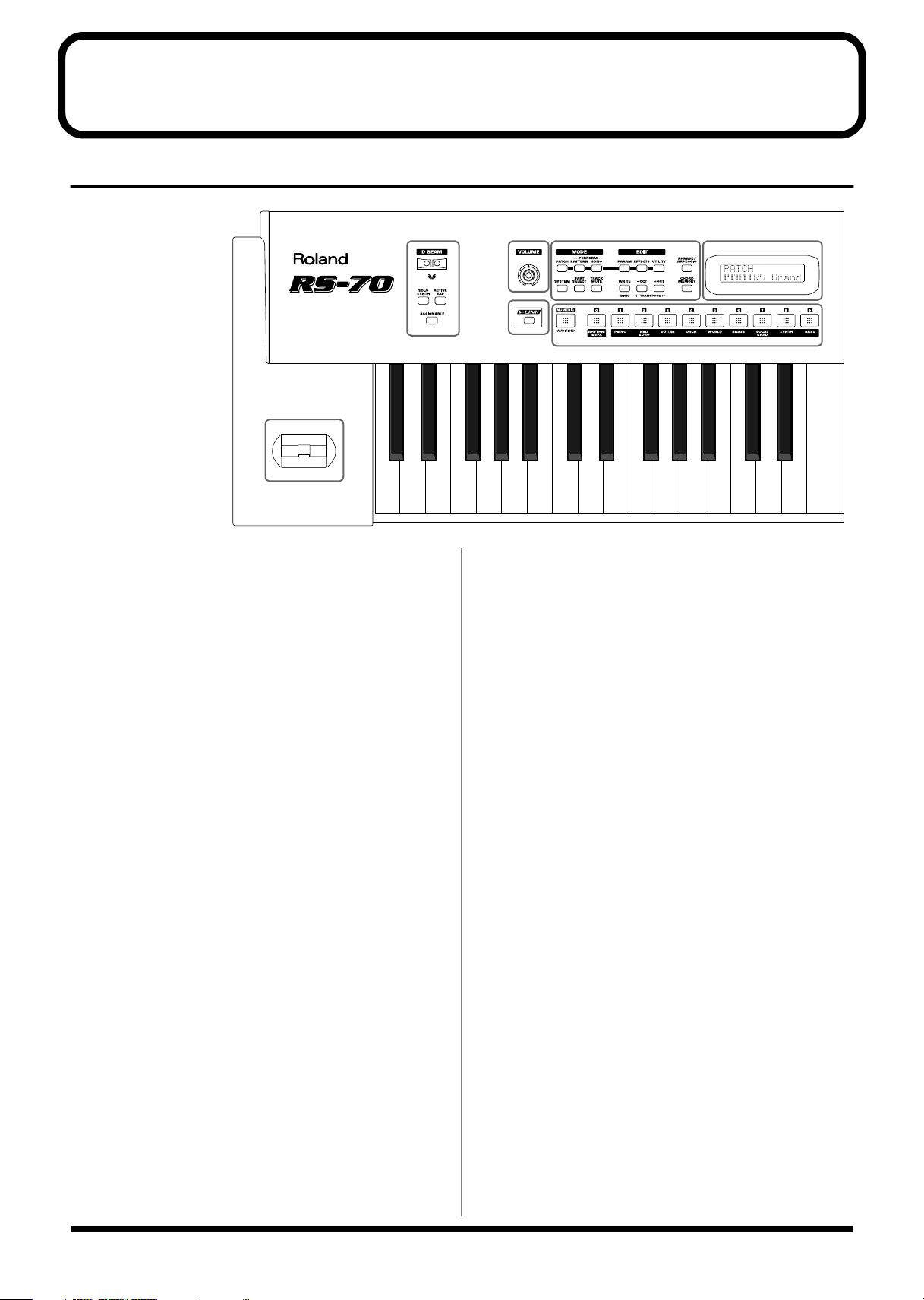
Front panel
fig.04-01.l
K
A
D BEAM CONTROLLER
You can apply a variety of effects to patterns and patches simply by
moving your hand (p. 35).
[SOLO SYNTH] (Solo Synthesizer) button
You can generate passages that sound as if you are rapidly playing
the keyboard.
[ACTIVE EXPRESS] (Active Expression) button
This lets you use the D Beam controller for Active Expression.
[ASSIGNABLE] button
This lets you assign a desired function to the D Beam controller (p.
37).
B
[VOLUME] knob
Adjusts the overall volume that is output from the rear panel
OUTPUT jacks and PHONES jack (p. 18).
C
AB
E
EDIT Section
[PARAM] (Parameter) button
This button accesses sound or performance settings (parameters).
The settings that are accessed will depend on the selected mode
(Patch/Pattern/Song) or state.
[EFFECTS] button
This button switches effects (reverb, chorus, MFX) on/off, and
accesses effect-related settings.
[UTILITY] button
In Patch/Pattern/Song modes, this button accesses various utility
functions, such as those for copying data or initializing sound
generator settings.
Others
[SYSTEM] button
This button accesses settings that affect the entire RS-70, such as
tuning, display contrast, and MIDI message reception.
[PART SELECT] button
When this button is lit, you can use the direct access buttons to select
a part to play from the keyboard or to edit (p. 54).
CD
F
MODE Section
[PATCH] button
Switches the RS-70 into the Patch mode (p. 53).
[PATTERN] button
Switches the RS-70 into the Pattern mode (p. 53).
[SONG] button
Switches the RS-70 into the Song mode (p. 53).
12
[TRACK MUTE] button
When this button is lit, you can use the direct access buttons to mute
(silence) individual parts of the music data that is playing (p. 67).
* You can manually play a part even when it is muted.
Page 13
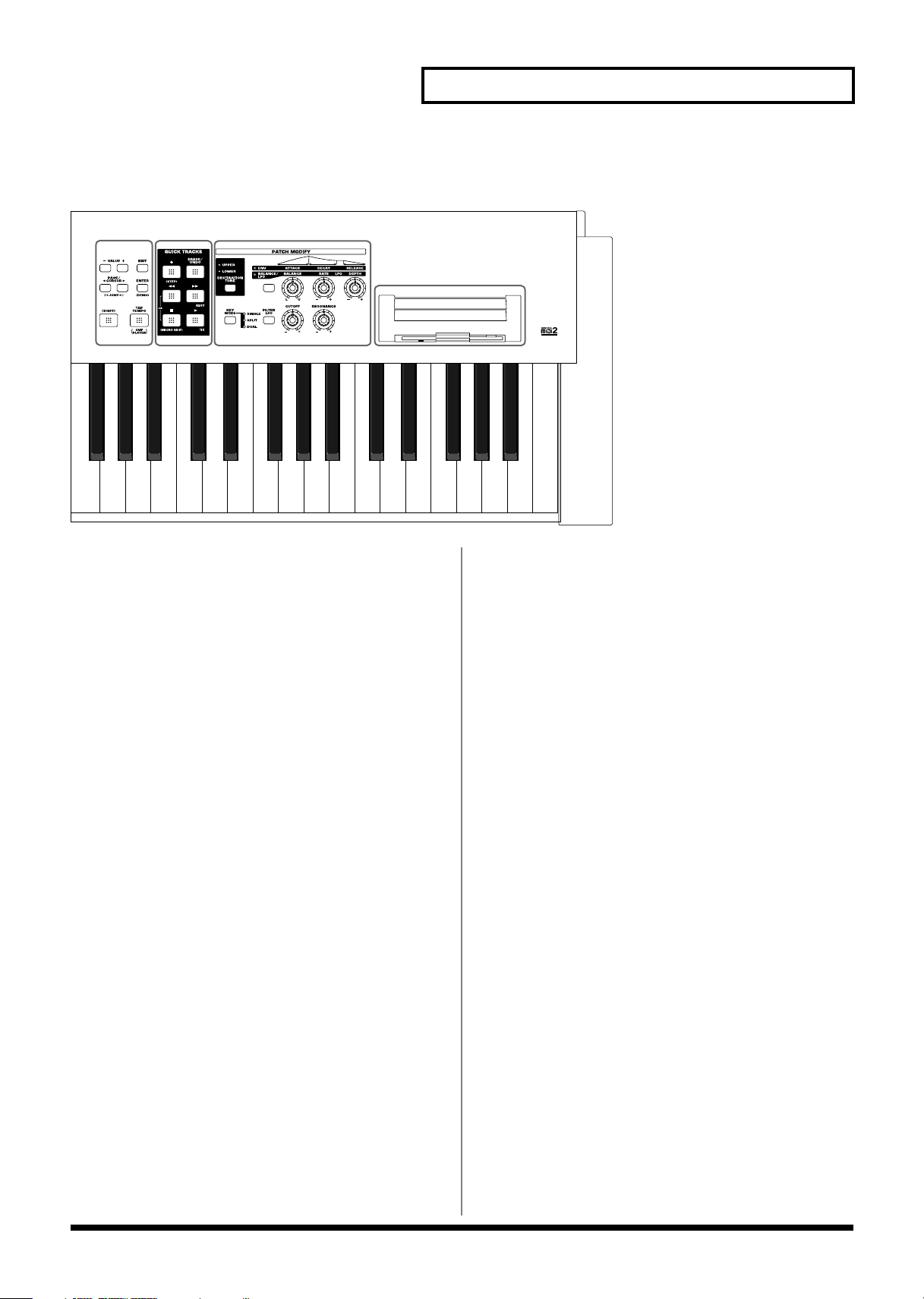
fig.04-01.r
Panel descriptions
GH I
J
[WRITE] / [DISK] button
WRITE: Saves patch/pattern/song settings or system settings.
DISK: By holding down [SHIFT] and pressing this button, you
can make settings related to the floppy disk (p. 119).
[-/+OCT] (Octave Shift) / [-/+TRANSPOSE]
(Transpose) buttons
- /+OCT: These buttons adjust the pitch of the keyboard
in octave steps (maximum +/-3 octaves) (p. 34).
- /+TRANSPOSE: Pressing either of these buttons while holding
down [SHIFT] allows you to transpose the
keyboard in semitone steps (-5–+6) (p. 35).
[PHRASE/ARPEGGIO] button
Switches phrase/arpeggio function on/off. To make settings for the
phrase/arpeggio, make this button light and then press [PARAM]
(p. 27).
[CHORD MEMORY] button
Switches chord memory function on/off. To make settings for the
chord memory function, get this button to light and then press
[PARAM] (p. 28).
D
DISPLAY
This displays information regarding the operation you are
performing.
F
[NUMERIC] / [AUDITION] button
NUMERIC:
AUDITION:
When this button is lit, the direct access buttons will
function as a numeric keypad. This lets you directly
input or specify a numerical value for the displayed
item (patch number or parameter).
By holding down [SHIFT] and pressing this button, you
can repeatedly listen to an audition phrase for the
currently selected patch (p. 26).
[0]–[9] (DIRECT ACCESS buttons)
In Patch mode, use these buttons to switch between the sound
categories printed on the panel (p. 24). In Pattern mode, use these
buttons to directly select a pattern to play by specifying the lowest
digit of the pattern number (p. 66). However, if the [NUMERIC],
[PART SELECT], or [TRACK MUTE] buttons are lit, the [0]–[9]
buttons will change to the corresponding function.
G
[VALUE -/+] buttons
Use these buttons to switch the number of an item (patch, pattern,
various parameters, etc.) in the display, or to increase/decrease a
value. While one of these buttons is first held down and the other is
pressed, the value then changes rapidly. Or, if you hold down
[SHIFT] while using these buttons, the value will change in larger
steps.
E
[V-LINK] button
Switches V-LINK on/off (p. 136).
13
Page 14
Panel descriptions
PAGE/CURSOR [ ]/[ ] /
JUMP [ ]/[ ] buttons
PAGE/CURSOR: Use these buttons to move between pages or to
move the cursor (p. 53).
JUMP: In grouped pages, you can hold down [SHIFT]
and use these buttons to move between groups
(p. 53).
While one of these buttons is first held down and the other is
pressed, the page or cursor then moves rapidly.
[EXIT] button
Press this button to return to the main screen of a mode, or when you
want to cancel the current operation.
[ENTER] button
Use this button to finalize a value or execute an operation.
[SHIFT] button
By holding down this button and pressing another button, you can
access a secondary function of that button (printed below the button
in square brackets).
[TAP TEMPO] / [SMF PLAYER] button
TAP TEMPO: Adjusts the tempo according to the timing at which
you tap this button. You can also use VALUE [-]/
[+] to adjust the tempo if desired (p. 67).
SMF PLAYER: You can hold down [SHIFT] and press this button
to select SMF Player mode (p. 47).
[] (Backward) button
Press this to “rewind” a pattern or song. If you hold down this
button as you press [ ], the pattern or song will “rewind” faster.
Or, if you hold down [SHIFT] while using this button, the value will
change in larger steps (p. 66, p. 114).
Press this button while holding down [ ] to return to the
beginning of the pattern or song.
[] (Forward) button/REST button
: Use this button to fast-forward a pattern or song. If you
hold down this button as you press [ ], the pattern
or song will fast-forward faster. Or, if you hold down
[SHIFT] while using this button, the value will change
in larger steps (p. 66, p. 114).
REST: During step recording, press this button to input a rest
(p. 76).
[] (Stop) button/MICRO EDIT button
: Press this button to stop playback of the pattern or
song.
MICRO EDIT: You can hold down [SHIFT] and press this button to
use the Microscope edit function (p. 76).
[] (Play) button/TIE button
: Press this button to start playback of the pattern or
song.
TIE: During step recording, press this button to input a tie
(p. 76).
H
QUICK SEQ (Quick Sequencer) section
* The buttons in this section are generally valid in Pattern mode, Song
mode and SMF Player mode.
[] (Recording) button / STEP button
: Press this to begin pattern or song recording.
STEP: By holding down [SHIFT] and pressing this button, you
can enter Step Recording (p. 75).
[ERASE/UNDO] button
This button erases recorded data or cancels the pattern edit
operation. During loop recording, you can use this to selectively
erase data just like a pencil eraser (p. 69). Immediately after
recording is finished, you can press this button to erase (undo) the
recording itself (p. 70). If you press it again, the Undo will be
cancelled (redo).
I
PATCH MODIFY section
[DESTINATION TONE] button
Selects either UPPER or LOWER as the tone to be edited.
Patch Modify select button
Selects whether the three knobs located at the right will edit the
envelope or the balance and LFO.
• If envelope is selected (ENV indicator lit)
[ATTACK] knob
Adjusts the attack speed of the sound (p. 32).
[DECAY] knob
Adjusts the speed at which the sound decays while you
continue holding the key (p. 32).
[RELEASE] knob
Adjusts the length of the release after you take your finger off
the key (p. 32).
14
Page 15
• If balance/LFO is selected (BALANCE/LFO
indicator lit)
[BALANCE] knob
Adjusts the LOWER and UPPER volume balance (p. 30).
[LFO RATE] knob
Adjusts the rate of the LFO effect, such as vibrato (p. 31).
[LFO DEPTH] knob
Adjusts the depth of the LFO effect, such as vibrato (p. 31).
[KEY MODE] button
Switches the Key Modes (p. 55).
[FILTER LFO] button
This determines whether the LFO changes the filter cutoff frequency
(ON), or the pitch (OFF) (p. 31).
Panel descriptions
[CUTOFF] knob
Changes the tone’s Cutoff Frequency value (p. 33).
[RESONANCE] knob
Changes the tone’s Resonance value (p. 33).
J
Floppy disk drive
3.5” 2DD/2HD floppy disks can be used. (Hereafter, this manual
will refer to “floppy disk” simply as “disk.”) To remove the disk,
press the eject button located at the right of the disk drive.
K
Pitch bend/Modulation lever
This allows you to control pitch bend or apply vibrato (p. 33).
15
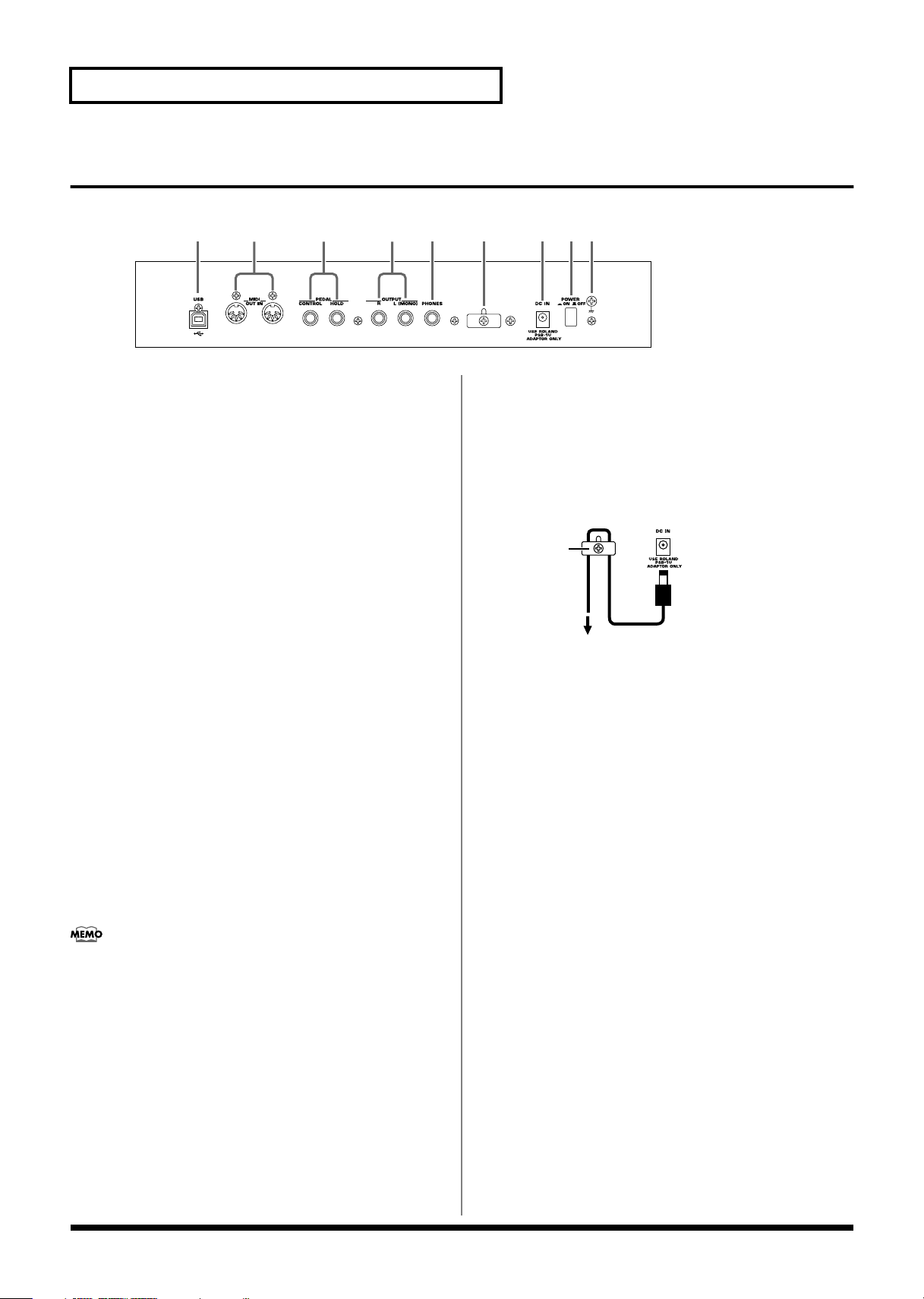
Page 16
Panel descriptions
Cord Hook
To the Power Outlet
The cord of
the supplied
AC Adaptor
Rear panel
fig.04-02
A BC EF G H ID
A
USB connector
This connector lets you use a USB cable to connect your computer to
the RS-70 (p. 139).
B
MIDI connectors (IN, OUT)
These connectors can be connected to other MIDI devices to receive
and transmit MIDI messages (p. 129). Use MIDI cables (sold
separately) to make connections.
IN: MIDI messages from an external device are received at this
connector.
OUT: MIDI messages are transmitted from this connector to an
external device.
C
PEDAL jacks
CONTROL:
An optional expression pedal (such as the EV-5), pedal switch (the
optional DP-2 or DP-8), or foot switch (the optional BOSS FS-5U) can
be connected to this jack (p. 17).
HOLD:
An optional pedal switch (such as the DP-2 or DP-8) or foot switch
(the optional BOSS FS-5U) can be connected to this jack for use as a
hold pedal (p. 17).
If you are using DP-8, set the DP-8’s function switch to “Switch.”
D
OUTPUT jacks
These jacks output stereo (L/R) audio signals to your amp or mixer.
For mono output, use the L jack.
F
Cord hook
To prevent the inadvertent disruption of power to your unit (should
the plug be pulled out accidentally), and to avoid applying undue
stress to the DC IN jack, anchor the power cord using the cord hook,
as shown in the illustration.
fig.CordHook.e
G
DC IN jack
Connect the AC adaptor here (p. 17).
Be sure to use only the supplied AC adaptor.
H
POWER switch
This switch turns the power on/off (p. 18).
I
Ground terminal
927
In some cases, depending on the environment in which the unit is installed,
the surface of the panel may sometimes feel rough and grainy. This is due
to an infinitesimal electrical charge, which is absolutely harmless. However,
if you are concerned about this, connect the ground terminal (see figure)
with an external ground. When the unit is grounded, a slight hum may
occur, depending on the particulars of your installation. If you are unsure of
the connection method, contact the nearest Roland Service Center, or an
authorized Roland distributor, as listed on the “Information” page.
E
PHONES jack
This is the jack for connecting headphones (sold separately) (p. 17).
16
Unsuitable places for connection
• Water pipes (may result in shock or electrocution)
• Gas pipes (may result in fire or explosion)
• Telephone-line ground or lightning rod (may be dangerous in
the event of lightning)
Page 17
Getting ready
Stereo headphones
AC adaptor
to AC power outlet
Audio
cable
Pedal switch (DP-2, DP-8)
or foot switch
(BOSS FS-5U)
Expression pedal (EV-5)
or pedal switch
Audio set etc.
Monitor speakers
(powered)
Mixer etc.
Power amp
Roland
• To prevent malfunction
and/or damage to
speakers or other
devices, always turn
down the volume, and
turn off the power on all
devices before making
any connections.
• To prevent the
inadvertent disruption
of power to your unit
(should the plug be
pulled out
accidentally), and to
avoid applying undue
stress to the AC adaptor
jack, anchor the power
cord using the cord
hook, as shown in the
illustration.
• Use only the specified
expression pedal (EV-5;
sold separately). By
connecting any other
expression pedals, you
risk causing
malfunction and/or
damage to the unit.
• Audio cables, MIDI
cables, and stereo
headphones are not
included. You will need
to purchase these items
from your dealer.
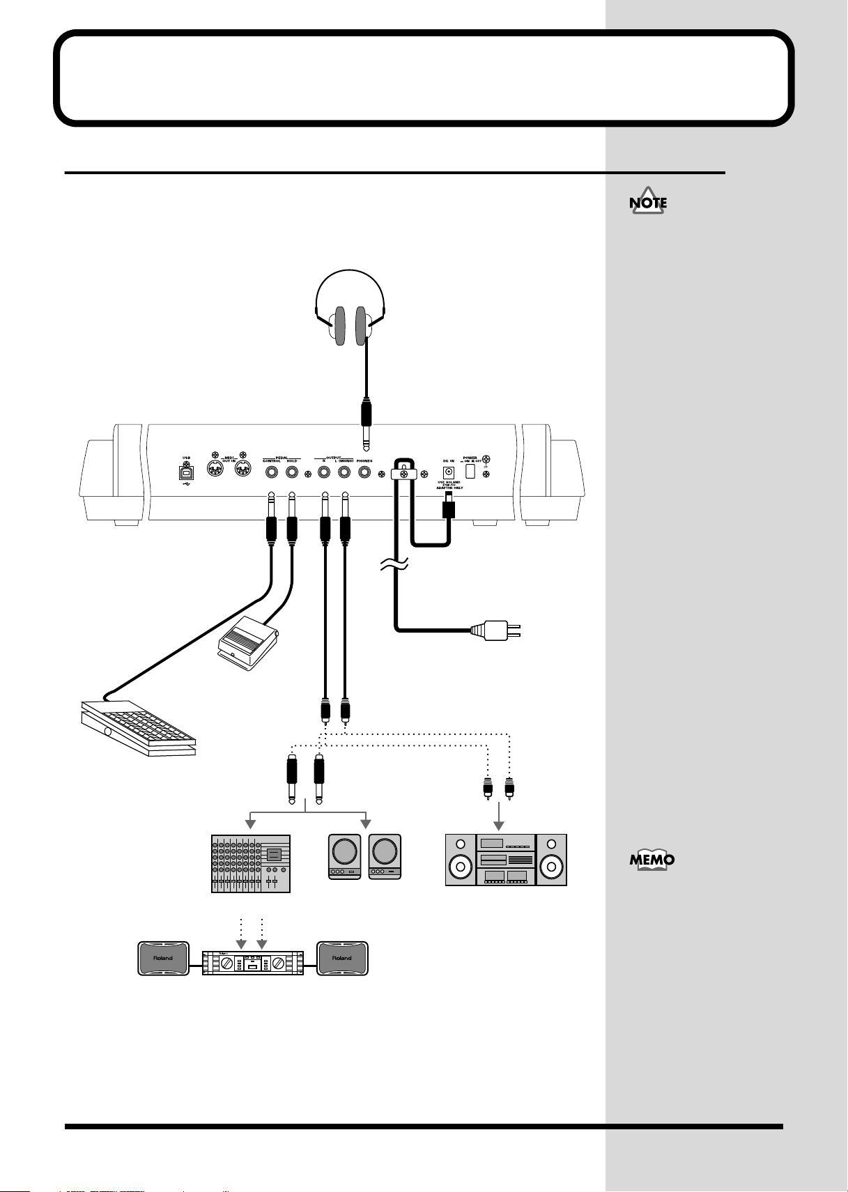
Connecting the RS-70 to external equipment
The RS-70 does not contain an amp or speaker. You’ll need to listen to it through
powered monitors, a mixer and connected monitors, a stereo system, or through
headphones.
Connect as follows when using the RS-70 as a stand-alone device.
fig.q01-01.e
1.
Before starting the connection procedure, make sure that the power to all
devices has been turned off.
2.
Connect the supplied AC adaptor to the RS-70, and then plug its other end
into a power outlet.
• In order to take full
advantage of the RS-70’s
performance, we
recommend using a
stereo amp/speaker
system, If you are using a
mono system, make you
connections to the
OUTPUT jack L MONO).
• CONTROL PEDAL jack
can also accommodate
pedal switches.
17
Page 18
Getting ready
Once the connections have
been completed (p. 17),
turn on power to your
various devices in the order
specified. By turning on
devices in the wrong order,
you risk causing
malfunction and/or
damage to speakers and
other devices.
b
3.
Connect the RS-70 and the external device as shown in the figure.
Use audio cables to connect audio equipment, such as an amp or speakers. If you are
using headphones, plug them into the PHONES jack. Connect pedal switches or
expression pedals as necessary.
If you want to know how to make the connections with another external device, refer
to:
Using the RS-70 to play an external MIDI sound module (p. 130)
Playing the RS-70’s sound generator from an external MIDI device (p. 131)
Recording to an external sequencer (p. 133)
Turning on/off the power
Turning on the power
1.
Before turning on the RS-70’s power, check the following:
• Are all devices connected properly?
• Are the volume controls of the RS-70 and any other connected equipment
turned to the minimum position?
• Is the AC adapter correctly connected to the RS-70?
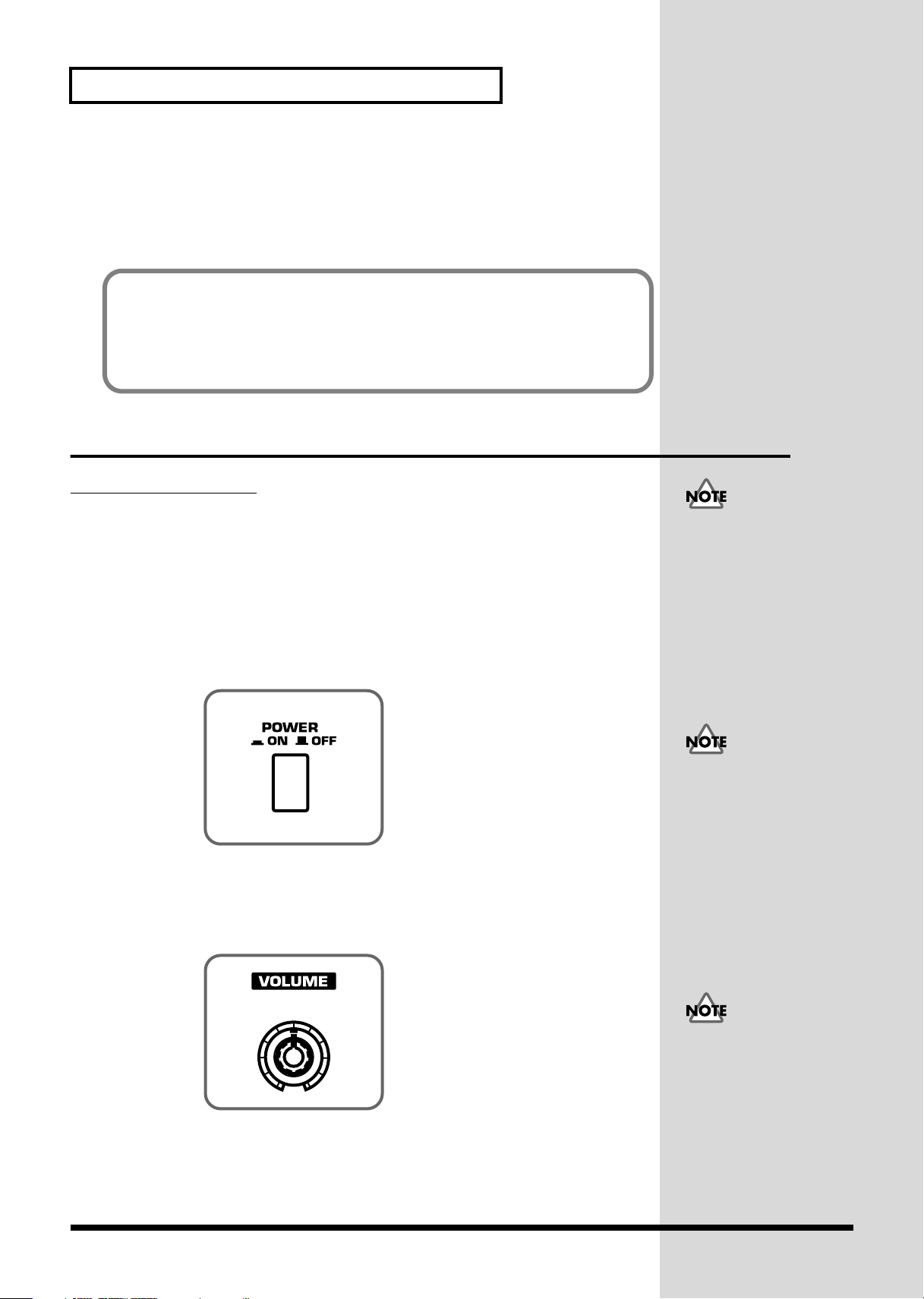
2.
Press the power switch on the rear panel of the RS-70 to turn on the power.
fig.q01-02
3.
Turn on the power of the connected audio devices.
4.
Play the RS-70’s keyboard and gradually raise the volume controls of the
RS-70, or the connected audio equipment to an appropriate volume level.
fig.q01-03
This unit is equipped with
a protection circuit. A brief
interval (a few seconds)
after power up is required
efore the unit will operate
normally.
18
Turn up the RS-70’s
volume level carefully.
Excessive volume can
damage connected audio
devices, your hearing, or
annoy your neighbors.
Page 19
Turning off the power
231
1.
Before you turn off the power, make sure of the following points.
• Are the volume controls of the RS-70 and the other connected equipment
turned to the minimum position?
• Have you saved the sounds or other data you’ve created? (p. 59, p. 64, p. 82,
p. 115)
2.
Turn off the power for all connected audio devices.
3.
Turn off the RS-70’s power switch.
Adjusting the display contrast
(LCD CONTRAST)
The characters in the display may be difficult to view immediately after turning on
the power or after extended use; this may also be because of where and how the
display is situated. Follow the steps below to adjust the display’s contrast.
fig.q01-04
Getting ready
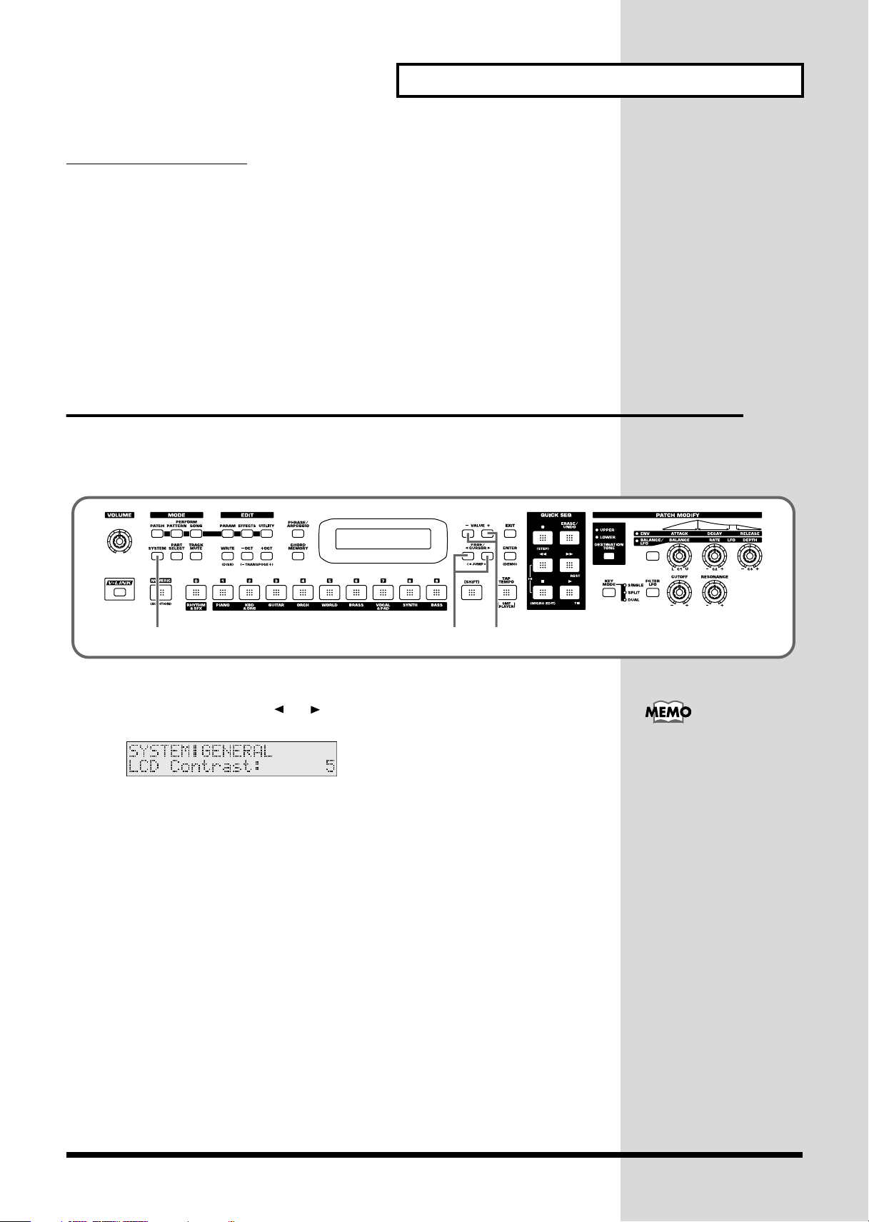
1.
Press [SYSTEM] so it is lit.
2.
Use PAGE/CURSOR [ ]/[ ] to select “LCD Contrast.”
fig.q01-05
3.
Use VALUE [-]/[+] to set the value (1–10).
The LCD CONTRAST
setting is saved
automatically, and is
retained even while the
power is off.
19
Page 20
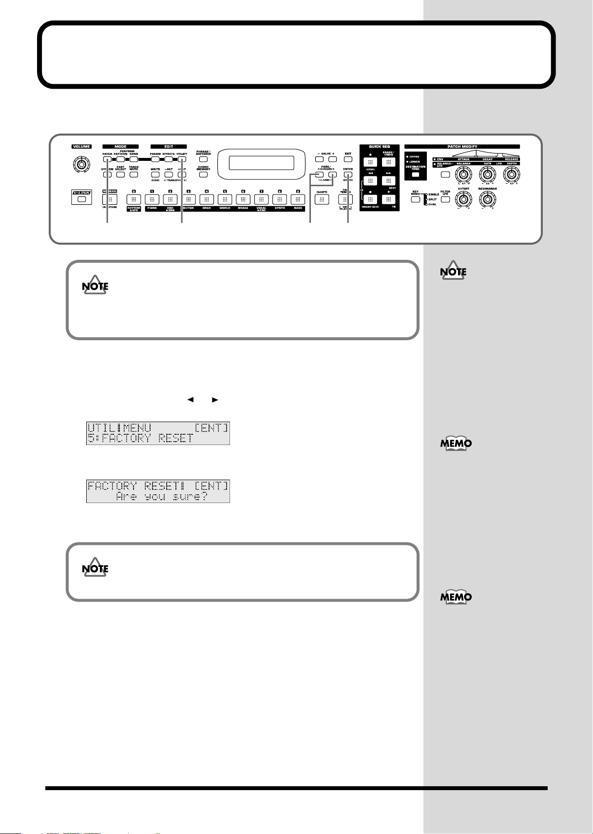
Reset to default factory settings (Factory Reset)
This restores all data in the RS-70 to the factory-set condition (
fig.q02-01
2
Be sure not to turn off the power while Factory Reset is being performed.
If the power is turned off or interrupted while Factory Reset is being
performed, the internal data may become corrupted.
1.
Press [PATCH] so it is lit and you are in Patch mode.
2.
Press [UTILITY] so it is lit.
3.
Use PAGE/CURSOR [ ]/[ ] to select “5:FACTORY RESET.”
fig.q02-02_40
31
Factory Reset
4, 5
).
If there is important data
you’ve created that’s stored
in the RS-70’s internal
memory, you must note
that all such data will be
discarded when a Factory
Reset is performed. If you
want to keep the existing
data, save it on a disk (p.
120).
4.
Press [ENTER].
fig.q02-03_40
5.
Press [ENTER] again to execute the Factory Reset.
The Factory Reset operation will require several minutes.
When the display indicates “COMPLETED,” the factory reset operation has been
completed.
Press [EXIT] to cancel the
factory reset.
Factory Reset can be
executed not only from
Patch mode, but also from
the Utility functions of
Pattern mode or Song
mode (p. 90, p. 118).
20
Page 21

Listening to the demo songs
The RS-70 contains Demo songs.
Here’s how to listen to the demo songs and experience the superb sounds and effects
of the RS-70.
fig.q03-01
2431
1.
Press [ENTER] while holding down [SHIFT].
fig.q03-02_40
2.
Use VALUE [-]/[+] to select the song that you wish to hear.
If you want to listen to all of the songs played in order, select “All Songs.”
3.
Press [ ] to start demo song playback.
The selected song is played back repeatedly.
When “All Songs” is selected, the entire selection of song is played back repeatedly.
While the demo songs are
playing back, playing the
keyboard will not produce
sound.
4.
Press [ ] to stop playback.
To return the keyboard to performance mode, press [EXIT].
981a, 982
• Unsaved settings changes may be lost when you start Demo Play. Carry out
the write procedure as required to save such data before listening to the
demo songs (p. 59, p. 64, p. 82).
• All rights reserved. Unauthorized use of this material for purposes other
than private, personal enjoyment is a violation of applicable laws.
• No data for the music that is played will be output from MIDI OUT.
Demo songs list
The RS-70 comes with 3 demos.
TightPocket / Ken Suzuki
Roland Corporation
Crystal Vision / Adrian Scott
Roland Corporation
Relax Me / Scott Wilkie
2003 Scott Wilkie Media (ASCAP)
21
Page 22

Memo
22
Page 23

Quick Start
23
Page 24
Try out the sounds
Selecting a patch
On the RS-70, the sounds you use for normal playing are called
analogous to an instrument held by a member of an orchestra.
Each patch consists of two tones; an
two tones to their own region of the keyboard (p. 55), and make independent settings
for each tone (p. 57).
■
Selecting a patch by category
The RS-70 allows you to rapidly select and call up a patch by specifying the type of
patch. All the patches are organized into 10 category groups.
Button
[1] PIANO (Pf) PNO AC.PIANO Acoustic Piano
[2] KBD &
[3] GUITAR (Gt) AGT AC.GUITAR Acoustic Guitar
[4] ORCH (Oc) STR STRINGS Strings
[5] WORLD (Wr) PLK PLUCKED Plucked (Harp, etc.)
[6] BRASS (Br) BRS AC.BRASS Acoustic Brass
[7] VOCAL &
[8] SYNTH (Sy) HLD HARD LEAD Hard Synth Lead
[9] BASS (Bs) BS BASS Acoustic & Electric Bass
[0] RHYTHM &
Category
Group
ORGAN (Ky)
PAD (Vo)
SFX (Rh)
Category Contents
EP EL.PIANO Electric Piano
KEY KEYBOARDS Other Keyboards
BEL BELL Bell, Bell Pad
MLT MALLET Mallet
ORG ORGAN Electric and Church Organ
ACD ACCORDION Accordion
HRM HARMONICA Harmonica, Blues Harp
EGT EL.GUITAR Electric Guitar
DGT DIST.GUITAR Distortion Guitar
ORC ORCHESTRA Orchestra Ensemble
HIT HIT&STAB Orchestra Hit, Hit
WND WIND Winds (Oboe, Clarinet, etc.)
FLT FLUTE Flute, Piccolo
ETH ETHNIC Other Ethnic
FRT FRETTED Fretted Inst (Mandolin, etc.)
SBR SYNTH.BRASS Synth Brass
SAX SAX Sax
BPD BRIGHT PAD Bright Pad Synth
SPD SOFT PAD Soft Pad Synth
VOX VOX Vox, Choir
SLD SOFT LEAD Soft Synth Lead
TEK TECHNO SYNTH Techno Synth
PLS PULSATING Pulsating Synth
FX SYNTH FX Synth FX (Noise, etc.)
SYN OTHER SYNTH Poly Synth
SBS SYNTH.BASS Synth Bass
DRM DRUMS Rhythm Set
PRC PERCUSSION Percussion
SFX SOUND FX Sound FX
BTS BEAT&GROOVE Beat and Groove
CMB COMBINATION Other Patches
upper tone
patches
and
lower tone
(Clav, Harpsichord, etc.)
. You can assign the
. A patch is
24
Page 25
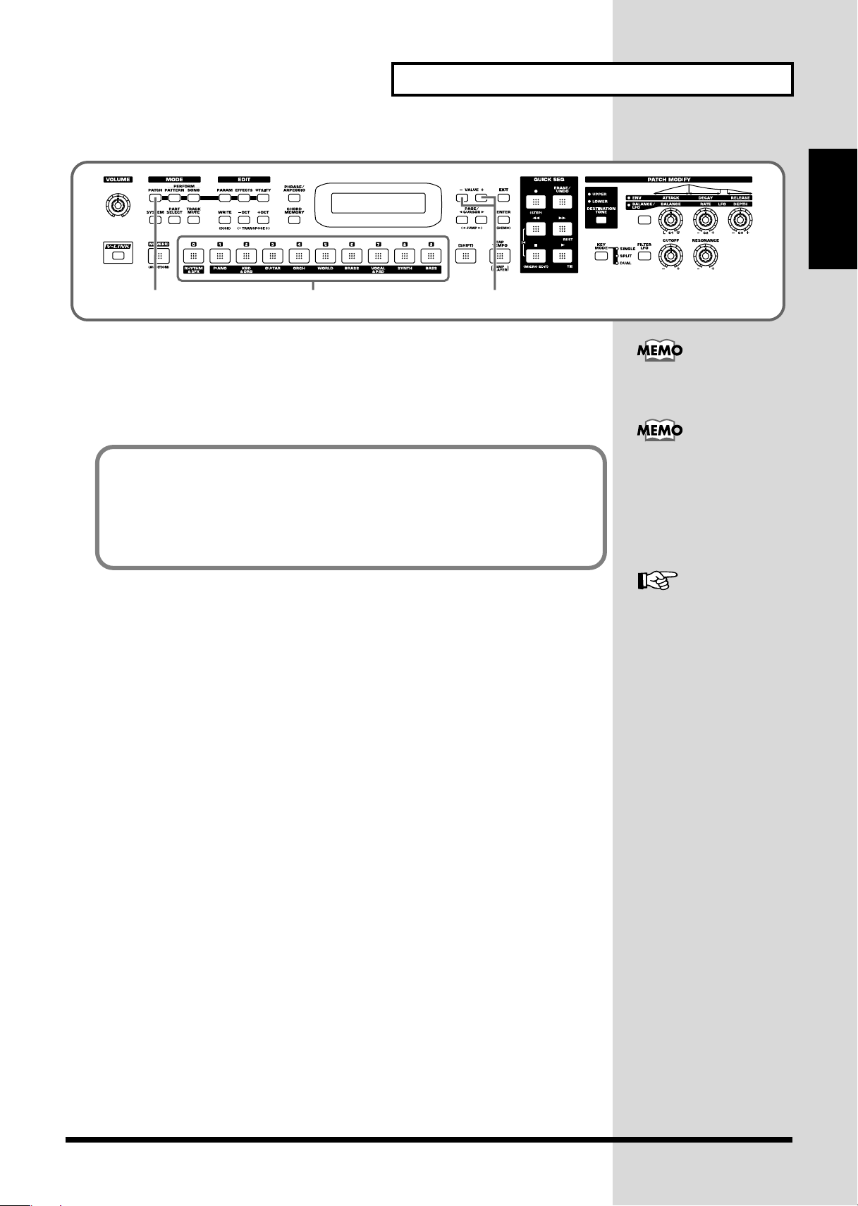
fig.q04-02
Selecting sounds by category
In Patch mode, the direct access buttons [0]–[9] act as category select buttons.
Since the patches you select for [0]–[9] (each category) will be remembered even
when the power is turned off, you can select ten favorite patches from the panel and
recall those patches instantly just by pressing [0]–[9].
Patch List
(p. 172)
21 3
1.
Press [PATCH] so it is lit and you are in Patch mode.
2.
Use [0]–[9] to specify the category group of the patch you want to select.
3.
Use VALUE [-]/[+] to select sounds within the category group.
Try out the sounds
Quick Start
The rhythm sets are
included in [0] (p. 26).
You can turn [NUMERIC]
on and use the [0]–[9]
numeric keys to input a
patch number directly.
Press [ENTER] to finalize
the number (p. 54).
25
Page 26
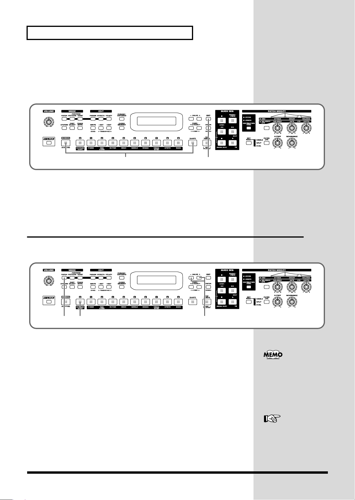
Try out the sounds
■
Selecting patches while listening to phrases
(Patch Audition)
Without playing keyboards, you can audition the sounds using phrases that have
been pre-programmed to be suitable for the character of each patch.
fig.q04-03
1.
While holding down [SHIFT], press [NUMERIC].
The currently selected patch will begin sounding.
2.
Select patches as described in
Selecting a patch by category
31
(p. 24).
3.
Press [EXIT] to stop the patch audition.
Selecting a rhythm set
The RS-70 provides rhythm sets that let you play different percussion instrument
sounds or special effects from each key.
fig.q04-04
1 2 3
1.
Press [PATCH] so it is lit and you are in Patch mode.
2.
Press [0] to select “RHYTHM & SFX.”
3.
Use VALUE [-]/[+] to switch rhythm sets.
There are patches other than rhythm sets in the Rhythm & SFX category group.
Rhythm sets have “Kit,” “Menu,” or “GM2” in their names.
With [0] pressed, you can
turn [NUMERIC] on and
use the [0]–[9] buttons to
input a rhythm set number
directly. Press [ENTER] to
finalize the number (p. 54).
26
Rhythm Set List (p. 178)
Page 27
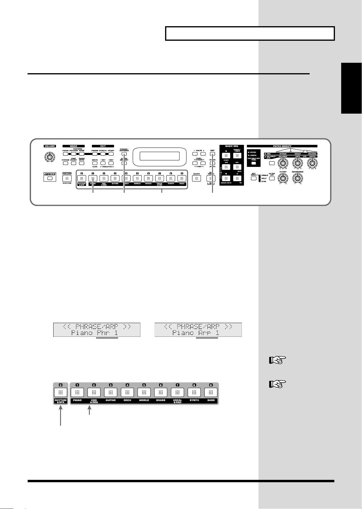
Playing arpeggios (Phrase/Arpeggio)
Try out the sounds
An arpeggio is a “broken chord” where each note is played separately. The
Arpeggio
and is also a convenient way to input a performance into the Quick Sequencer. Since
the RS-70 provides arpeggio
select, you can produce appropriate arpeggios immediately.
You can also select
one key, without pressing a chord (p. 72).
fig.q04-05
1.
In Patch mode, press [1] to select piano sounds.
2.
Press [PHRASE/ARPEGGIO] so it is lit.
3.
Play the keyboard.
The instrument will play an arpeggio, according to the notes you have just voiced.
function lets you produce an arpeggio simply by holding down a chord,
templates
Phrase Template
1 2, 6 5
that are suitable for the various sounds you
which allows you to play arpeggio using only
4
Phrase/
Quick Start
■
Changing the way in which the arpeggios are sounded
Then, try to change the way in which the arpeggios are sounded.
Settings that specify how arpeggios are sounded are provided as
By switching templates, you can change the way in which the arpeggios are
sounded.
4.
Press [0]–[9].
fig.q04-06_40
Play a phrase
by pressing one key.
It switches to an arpeggio template suitable for the selected sound.
Pressing [0] will select the user template.
fig.q04-07a
Preset (Arpeggio/Phrase) templates
User templates
templates
Play an arpeggio
by pressing a chord.
.
User template (p. 28)
Arpeggio Template List
(p. 184)
27
Page 28
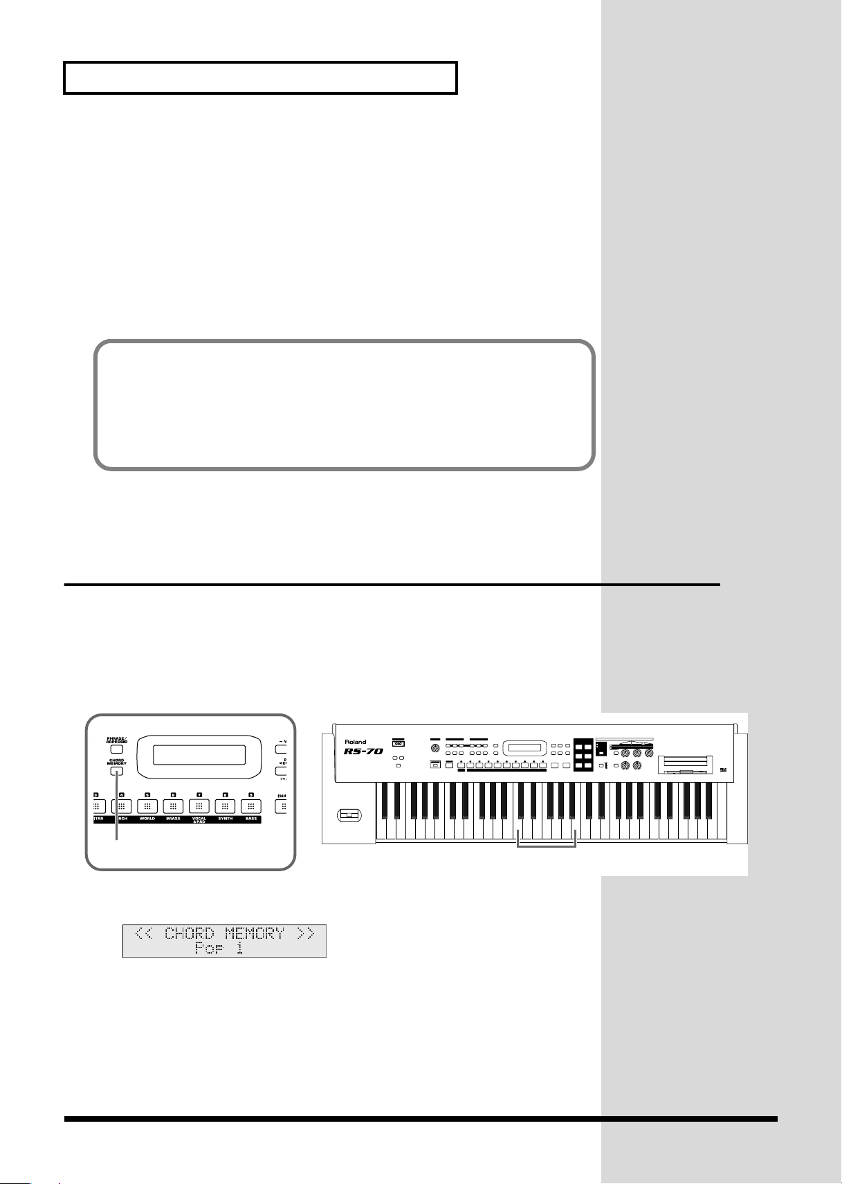
Try out the sounds
5.
When you press [EXIT], the Arpeggio function will remain on and you will
return to the previous screen.
If you want to select an arpeggio template once again, press [PHRASE/ARPEGGIO]
so it goes out, and then press [PHRASE/ARPEGGIO] once again so it is lit.
The selected arpeggio template remains stored in memory even while the power is
off.
6.
To finish playing arpeggios, press [PHRASE/ARPEGGIO] again so the
indicator goes out.
User template
The user template lets you set the various arpeggio template parameters as desired.
On the RS-70 you can store eight different user templates. With [0] pressed, use
VALUE [-]/[+] to select other user templates you have created.
For further information on how to make user templates, refer to Creating your own
arpeggio template (User Template) (p. 72).
Playing a chord at the touch of a finger
(Multi-chord Memory)
Chord Memory is a function that lets you play a chord simply by touching just one
key to which a “Chord Form” has been registered. On the RS-70 you can register
different chord forms to each key and save these chord forms as sets (
memory
user chord sets, these are a convenient way to get immediate results, such as when
inputting music into the Quick Sequencer.
fig.q04-08
) and recall them when desired. If you save typical chord progressions as
1
1.
Press [CHORD MEMORY] so it is lit.
fig.q04-09_40
multi-chord
Tw elve chord forms have been assigned
from C to B.
28
The Chord Memory function will be turned on, and the chord set name will be
displayed.
2.
Play the keyboard.
The chord of the specified structure will sound according to the note name of the key
you played.
Page 29
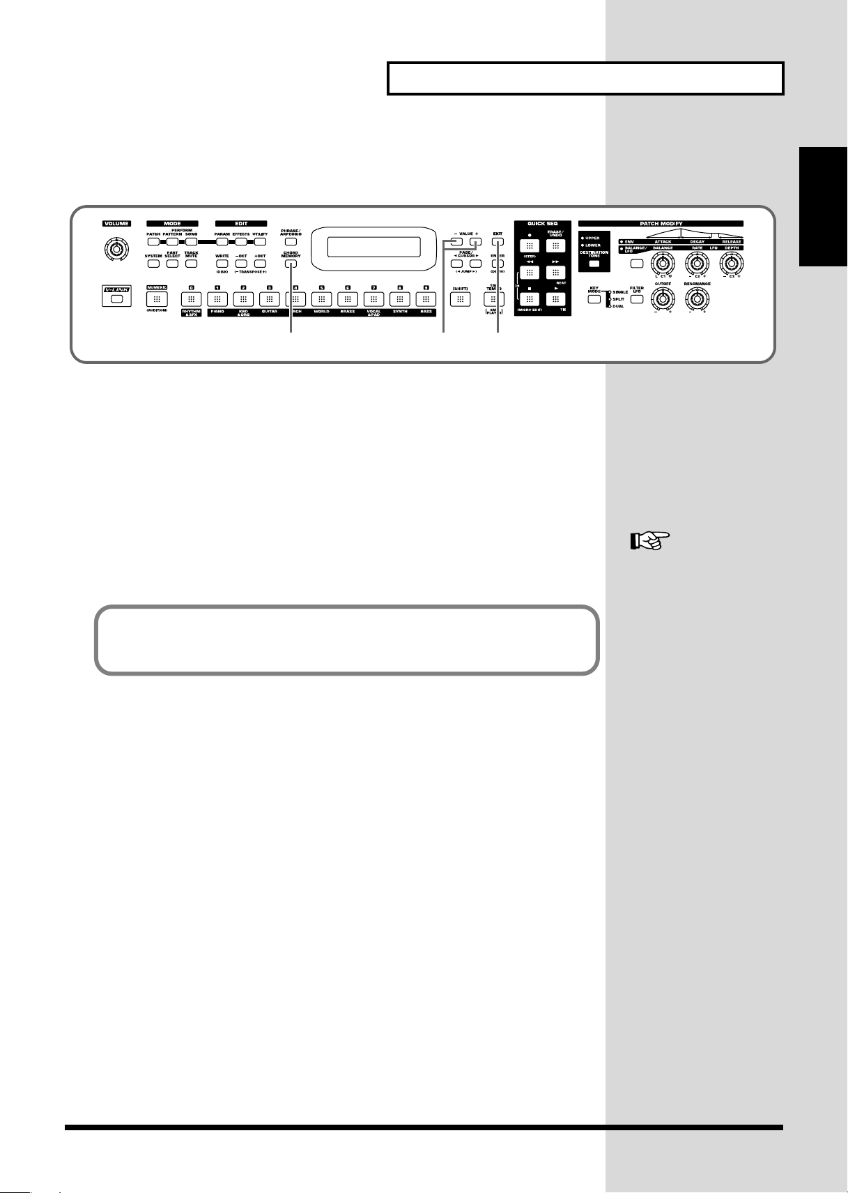
■
Switching chord sets
Then, try to change chord sets.
fig.q04-10
Try out the sounds
Quick Start
5
3.
Use VALUE [-]/[+] to select a Chord Set.
The user chord set appears after the preset chord sets.
4.
When you press [EXIT], the Multi-chord Memory function will remain on
43
and you will return to the previous screen.
If you want to select a chord set once again, press [CHORD MEMORY] so it goes out,
and then press [CHORD MEMORY] once again so it is lit.
The selected chord set remains stored in memory even while the power is off.
5.
To turn off the Multi-chord Memory function, press [
CHORD MEMORY
again so the indicator goes out.
You can create your own chord set by saving chords you have created.
For further information, refer to Creating an original chord set (User Chord Set)
(p. 74).
]
Multi-chord Set List (p.
186)
29
Page 30
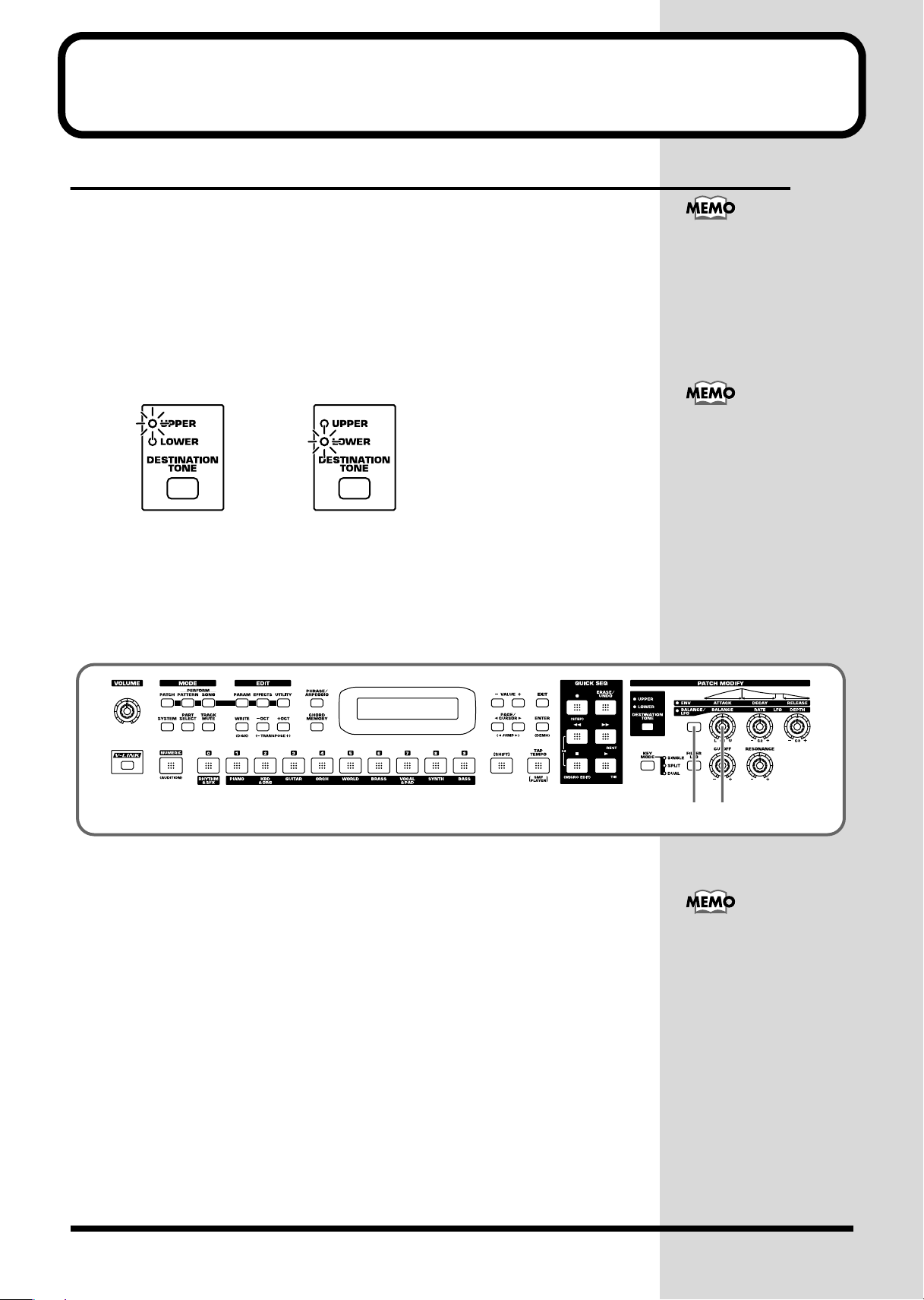
Applying various effects to the sound
Changing the tone with the knobs (Patch Modify)
Using the five panel knobs, you can change the tone in real time.
On the RS-70, each patch consists of two tones; the
(p. 50). The way that the tones are sounded (Single/Split/Dual) is saved in each
patch, and you can change this using [KEY MODE] (p. 55).
■
Selecting the tone that you want to modify
(DESTINATION TONE)
Use the [DESTINATION TONE] button to specify whether you will modify the
upper or the lower tone.
fig.q05-01
• UPPER lit: Only the upper tone will be modified
• LOWER lit: Only the lower tone will be modified
• Both lit: Both the upper and lower tones will be modified
upper tone
and the
lower tone
Patch Modify applies +/-
adjustments relative to the
settings of the original tone.
Depending on the tone you
select, this may not always
produce a noticeable
change in the sound.
For a rhythm set, Patch
Modify applies to the set as
a whole.
■
Adjusting the volume balance of the two tones
You can use a knob to control the volume balance of the upper tone and lower tone.
fig.q05-02
1.
Press the patch modify select button to make the BALANCE/LFO indicator
light.
2.
Turn the [BALANCE] knob.
Turning this to the right increases the volume of the upper tone, while turning it to
the left increases that of the lower tone.
2
1
You cannot change the
volume balance for rhythm
sets.
30
Page 31

■
[FILTER LFO] does not
take effect on a rhythm set.
Vibrato and Wah effects (LFO)
The LFO, short for “low frequency oscillator,” makes changes to the sound in
periodic fashion. Changing the pitch with the LFO produces the “
and by changing the filter cutoff frequency with the LFO, you get what is called the
“
wah effect
fig.q05-03
.”
Applying various effects to the sound
vibrato effect
,”
Quick Start
1.
Press the patch modify select button to make the BALANCE/LFO indicator
light.
2.
Make sure that [FILTER LFO] is off (unlit).
When [FILTER LFO] is off, the two LFO knobs will adjust the vibrato effect.
3.
Turn the [LFO DEPTH] knob.
Turning this to the right (clockwise) increases the depth of the undulating sound,
while turning it to the left (counterclockwise) makes the undulation shallower and
milder.
4.
Turn the [LFO RATE] knob.
Turning this to the right (clockwise) increases the speed of the undulating sound,
while turning it to the left (counterclockwise) slows the undulation down.
5.
Press [FILTER LFO] so it is lit.
When [FILTER LFO] is on, the two LFO knobs will adjust the wah effect.
6.
Turn the [LFO DEPTH] knob.
Turning this to the right (clockwise) increases the depth of the undulating sound,
while turning it to the left (counterclockwise) makes the undulation shallower and
milder.
2, 51
If it is on (lit), press
[FILTER LFO] once again
so it goes out.
3, 64, 7
7.
Turn the [LFO RATE] knob.
Turning this to the right (clockwise) increases the speed of the undulating sound,
while turning it to the left (counterclockwise) slows the undulation down.
31
Page 32

Applying various effects to the sound
b
12
3 4
■
Changing the sound’s volume (ENVELOPE)
The volume continues to change from the time a key is pressed to when it is released.
A: Attack Time: The time from when the keyboard is pressed until the maximum
tonal change is reached.
D: Delay Time: The time from when the maximum tonal change is reached until the
Sustain Level is reached.
S: Sustain level: Volume that is sustained while you hold down the key
R: Release Time: The time from when the keyboard is released until the sound
disappears.
Use the ENVELOPE 3 knobs to change the A, D, and R times.
* Each tone has its own Sustain level, which cannot be modified.
fig.q05-04.e
A: Attack time
Volume
AD R
Note-on
fig.q05-05
D: Decay time
R: Release time
Sustain
Level
Note-off
Sound ends
Time
The “envelope” is the curve
that shows how the volume
of an instrument changes
from the beginning of a
note to its end. Each
musical instrument has a
distinctive type of
envelope, but this can
change depending on how
the instrument is played,
and is an important factor
in the character of the
sound. For example, when
a trumpet is blown strongly
it produces a piercing
sound with a rapid attack,
ut when blown softly it
produces a gentler and
more muted attack.
1.
Press the patch modify select button so the ENV indicator is lit.
2.
Turn the [ATTACK] knob.
Turning this to the right (clockwise) increases the time it takes for the sound to rise,
while turning it to the left (counterclockwise) shortens this time.
3.
Turn the [DECAY] knob.
Turning this to the right increases the time it takes for the sound to reach the Sustain
Level, while turning it to the left shortens this time.
4.
Turn the [RELEASE] knob.
Turning this to the right increases the time it takes for the sound to disappear, while
turning it to the left shortens this time.
32
Page 33

Applying various effects to the sound
■
Changing the brightness of the sound and adding
special qualities (CUTOFF/RESONANCE)
The sound generator section of the RS-70 contains a
frequency regions of the sound. [CUTOFF] specifies the frequency (cutoff frequency)
at which the filter will begin to modify the sound, and [RESONANCE] boosts the
region near the cutoff frequency to add a distinctive character to the sound.
fig.q05-06
1.
Turn the [CUTOFF] knob.
filter
that can cut or boost specific
Quick Start
1 2
Turning this to the right (clockwise) brightens the sound, while turning it to the left
(counterclockwise) makes the sound seem darker.
2.
Turn the [RESONANCE] knob.
Turning this to the right makes the sound more distinctive, while turning it to the left
reduces these characteristics.
Using a lever to modify the sound
■
Changing the sound’s pitch in real time
(Pitch Bend Lever)
While playing the keyboard, move the lever to the left to lower the pitch, or
to the right to raise the pitch.
fig.q05-07.j
Pitch Bend
You can set up to a two-octave pitch bend range, adjustable in semitones.
For further information, refer to
Pitch Bend Range
(p. 58).
Independently for each
patch, you can specify
whether the effect is to be
applied to the upper or the
lower tone (p. 57).
Adding a vibrato effect to the sound (Modulation Lever)
■
While playing the keyboard, move the lever away from you to add a vibrato effect.
fig.q05-08.j
Modulation
When you want to use the Modulation Lever to add effects other than vibrato, refer
to
Mod (Modulation Assign)
(p. 126).
33
Page 34

Applying various effects to the sound
Using a pedal to modify the sound
With an external pedal, such as an expression pedal (the optional EV-5), pedal switch
(the optional DP-2/8) or foot switch (the optional BOSS FS-5U) connected to the
CONTROL PEDAL jack, you can then use the pedal to make changes in the tone.
Just as with the Modulation lever, you can select the function affected when the
pedal is pressed.
For further information, refer to
fig.q05-09
* When you want to apply the effect that causes the sounds being played to continue playing
(called the “hold effect”), connect a pedal switch (the optional DP-2/8) or foot switch (the
optional BOSS FS-5U) to the PEDAL HOLD jack.
Pedal (Pedal Control Assign)
(p. 126).
If you are using DP-8, set
the DP-8’s function switch
to “Switch.”
Shifting the keyboard range in one-octave
steps (Octave Shift)
Octave Shift is a function that shifts the pitch of the keyboard in one-octave units.
This lets you shift the range of the keyboard to the most convenient range for
playing. This is also convenient in a situation below.
When playing sounds outside the keyboard’s range
While the RS-70 features a 61-key keyboard, with some songs you may want to play
notes even higher or lower. Also, when playing a Rhythm Set etc., there may be
percussion instruments that the RS-70’s keyboard is not able to access. In such cases,
you can use the Transpose function to play these notes.
fig.q05-10
1
34
1.
Use OCT [-]/[+] to transpose the pitch.
You can transpose the pitch of the keyboard in 1 octave units (-3– +3 octaves)
Page 35

Applying various effects to the sound
Moving the key range in half-steps (TRANSPOSE)
This function moves the key range in half-step units. This is convenient in situations
like the ones below.
When matching the vocalist’s register
Sometimes melodies may extend outside a vocalist’s register. Therefore, if you want
to perform with the song changed to a different key, you can play the song in a new
key while still using the same fingering as before.
When changing from a difficult key to one that is easy to play
You can use simple fingerings to play difficult songs that include numerous sharps or flats.
When playing with the tone of a transposed instrument
You can play the patches of a transposed instrument just as it is written in the score.
fig.q05-11
Quick Start
1 1
1.
While holding down [SHIFT], press OCT [-]/[+].
You can transpose your performance over a range of -5–+6 semitones.
Waving your hand over the D Beam
(D Beam Controller)
The D Beam controller can be used simply by waving your hand over it. Of the three
buttons, one is assigned to the solo synth, another to the active expression effect, and
the third button can be assigned to the function of your choice. You can also create
effects in which the sound changes instantaneously, in a way that would not be
possible by operating a knob or the bender lever.
fig.q05-12
2
1
1.
Press [SOLO SYNTH], [ACTIVE EXPRESS], or [ASSIGNABLE] so it is lit.
If you select [ASSIGNABLE], the function assigned to the D Beam controller will
appear in the display.
fig.q05-13_40
35
Page 36

Applying various effects to the sound
The usable range of the D Beam controller
The following diagram shows the usable range of the D Beam controller. Waving
your hand outside this range will produce no effect.
fig.q05-14
Either [SOLO SYNTH], [ACTIVE EXPRESS], or
[ASSIGNABLE] will blink while the D Beam controller is
responding. When your hand leaves the usable range of the D
Beam controller, the button will stop blinking, and will
remain lit.
* The sensitivity of the D Beam controller will change depending
on the amount of light in the vicinity of the unit. If it does not
function as you expect, adjust the sensitivity as appropriate for
the brightness of your location (p. 38). Also, the usable range of
the D Beam controller will be considerably reduced when used
under strong, direct sunlight. Please be aware of this when using
the D Beam controller outside.
2.
While playing the keyboard to produce sound, place your hand over the D
Beam, and slowly move it up and down.
An effect will be applied to the sound, depending on the function that is assigned to
the D Beam controller.
3.
To turn off the D Beam controller, press the button once again to turn it off.
■
Effects that can be used with the D Beam controller
SOLO SYNTH
This lets you generate passages that sound as if you are playing the keyboard
rapidly. For example, if you hold down the four notes C, D, E, and G with your right
hand and move your left hand over the D Beam, a phrase such as “C D E G C D E G
...” will be repeated.
For example, you can use the D Beam to play a synth solo on a synth-lead type
sound, and hold chords using a long, sustaining sound to create the impression of
harp playing.
The chord memory function also provides a chord set that contain notes of a specific
scale and is designed for use with this function (16. Scale Set).
ACTIVE EXPRESS (Active Expression)
36
You can use the D Beam as an Active Expression function. If you assign the Active
Expression function to a patch that consists of dual tones (a patch whose
[KEYMODE] is set to “DUAL”), you can create tonal changes for greater
expressiveness, and to emphasize the forte passages in your playing.
The patches suitable for active expression have “AEx” in their names.
The explanations of each
type in this manual are for
when the D Beam Polarity
is set to “NORMAL” (p. 38).
With [SOLO SYNTH]
switched on, pressing the
keyboard alone will not
result in the production of
sound. You need to move
your hand over the D Beam
while you hold down keys.
If the Active Expression
Switch (p. 57) of the patch
is turned OFF, this will be
conventional expression
(volume change).
You will hear no sound if
you play the keyboard
when Active Expression
has set the volume to 0.
Page 37

ASSIGNABLE
Specifies a function controlled by the D Beam controller.
Use VALUE [-]/[+] and select one of the following functions.
Applying various effects to the sound
Value
MODULATION
PORTA TIME CC05 Portamento Time (p. 58)
VOLUME CC07 Level
BALANCE CC08 The volume balance of LOWER and UP-
PAN CC10 Pan (p. 57)
EXPRESSION CC11 Level
PORTAMENTO CC65 Portamento Switch (p. 58)
SOSTENUTO CC66 Holds the sound of the key being pressed
SOFT CC67 Softens the Tone
RESONANCE CC71 Tone Filter Resonance (p. 59)
RELEASE TIME CC72 Tone Envelope Release Time (p. 59)
ATTACK TIME CC73 Tone Envelope Attack Time (p. 59)
CUTOFF CC74 Tone Filter Cutoff (p. 58)
DECAY TIME CC75 Tone Envelope Decay Time (p. 59)
LFO RATE CC76 Tone LFO Rate (p. 58)
LFO DEPTH CC77 Tone LFO Depth (p. 58)
LFO DELAY CC78 Tone LFO Delay (p. 58)
CHO SEND LEVEL CC93 Chorus Send Level (p. 57)
REV SEND LEVEL CC91 Reverb Send Level (p. 57)
MFX PARAMETER1 CC12 The parameter specified by Multi-effect
MFX PARAMETER2 CC13 The parameter specified by Multi-effect
AFTERTOUCH ---BEND UP ---- Pitch bend effect (center
BEND DOWN ---- Pitch bend effect (center
SEQ START/STOP ---- Starts and stops the Quick Sequencer
In Patch mode, the effect will apply to the patch. In Pattern mode, the effect will
apply to the patch assigned to the current part. Use [DESTINATION TONE] to
specify the tone (p. 30).
“TxCC#” refers to the controller number of control change messages sent from the
MIDI OUT connector when the D Beam controller is operated. When set to
AFTERTOUCH, Channel Aftertouch messages are sent. Set to AFTERTOUCH
mainly when you want to control an external sound generator with Aftertouch
messages.
Receiving these control change messages from the MIDI IN connector produces the
same effect as moving the D Beam controller.
Tx CC# Function/Parameter Changed
CC01 Vibrato Effect
PER tones (p. 56)
Control 1 (p. 95)
Control 2 (p. 95)
→
up)
→
down)
Quick Start
* When set to MFX PARAMETER1 or MFX PARAMETER2, be sure to note the following.
• When the multi-effects Type is set to 01: STEREO EQ (p. 95) or 42: LOFI (p. 109),
Level is changed regardless of whether MFX PARAMETER1 or MFX
PARAMETER2 is selected.
• When the multi-effects Type is set to 23: 2V PCH SHIFT (p. 103), or 24: FB PCH
SHIFT (p. 104), the two parameters are changed simultaneously.
* When making the LFO RATE, LFO DEPTH or LFO DELAY settings, the effect achieved
differs depending on whether [FILTER LFO] is on or off. When [FILTER LFO] is off, the LFO
alters the pitch (vibrato effect). When [FILTER LFO] is on, the LFO changes the Filter Cutoff
frequency (wah effect).
37
Page 38

Applying various effects to the sound
■
Adjusting the sensitivity of the D Beam controllers
(D BEAM SENS)
The sensitivity of the D Beam controller will change depending on the amount of
light in the vicinity of the unit. If it does not function as you expect, adjust the
sensitivity as appropriate for the brightness of your location. Increasing this value
will raise the sensitivity.
1.
Press [SOLO SYNTH], [ACTIVE EXPRESS], or [ASSIGNABLE] so it is lit.
2.
Press [PARAM].
3.
Use PAGE/CURSOR [ ]/[ ] to select “Sens.”
fig.q05-16_40
4.
Use VALUE [-]/[+] to adjust the sensitivity.
Value:
As you increase this value, the D Beam controller will become more sensitive.
Normally, you will leave it at a setting of “5.”
5.
Press [EXIT] or [PARAM] to return to the previous screen.
■
Changing the polarity of the change
1–10
(D BEAM POLARITY)
By changing the D Beam Polarity setting, you can invert the direction of the effect
that is applied.
1.
Press [SOLO SYNTH], [ACTIVE EXPRESS], or [ASSIGNABLE] so it is lit.
2.
Press [PARAM].
3.
Use PAGE/CURSOR [ ]/[ ] to select “Polarity.”
fig.q05-17_40
4.
Use VALUE [-]/[+] to change the polarity.
Value:
5.
Press [EXIT] or [PARAM] to return to the previous screen.
NORMAL, REVERSE
This setting remains stored
in memory even while the
power is off.
This setting remains stored
in memory even while the
power is off.
38
Page 39

Applying various effects to the sound
1
2
33
Using the RS-70 effects
Three separate effects are always available in the RS-70. You can independently edit
each effect’s settings.
Multi-Effects
The RS-70 contains 47 different multi-effects, including distortion and a rotary
speaker simulation.
Chorus
Chorus adds a sense of depth and spaciousness to patches.
Reverb
Reverb adds ambient characteristics that emulate the sound of various physical
spaces, such as concert halls or auditoriums.
■
Turning effects on and off (Master Effects Switch)
fig.q05-18
Quick Start
Turn on a switch to enable the corresponding effect (multi-effect, chorus, reverb).
You may wish to turn these switches off when you want to listen to the unprocessed
sound while editing it, or if you are using an external effects processor and do not
want to use the built-in effects.
When shipped from the factory, all three effects are set to ON.
1.
Press [PATCH] so it is lit and you are in Patch mode.
2.
Press [EFFECTS] so it is lit.
The on/off state of each effect (multi-effect, chorus, reverb) will be displayed.
fig.q05-19_40
3.
Use PAGE/CURSOR [ ]/[ ] to select the effect type, and use VALUE
[-]/[+] to turn to switch it on/off.
When you play the keyboard in this state, the effects whose master effect switch is
turned on will be applied to the patches.
When the cursor is located at “Rev” and you want to edit the effect settings, press
PAGE/CURSOR[ ], and the effect parameters will be displayed one after another
starting with the multi-effect (MFX) parameters.
For further information, refer to
Making effects settings
(p. 93).
The On/Off settings for
each Effect affect the RS-70
as a whole (i.e., are system
settings). This setting
remains stored in memory
even while the power is off.
39
Page 40

Using the sequencer to create a pattern
b
The RS-70’s
only rhythms. This means that you don’t need to input the drums from scratch in
order to create your own melodies or patterns. Simply play the keyboard while you
listen to a rhythm pattern repeat, and practice until you find a bass or melodic line
you like. When you have come up with something, add layers for additional parts to
create your own original pattern. Patterns that you create in this way can be
connected to make a longer song.
The RS-70 makes it easy for you to create songs. While continuing the looped
playback, you can change the part you are recording, switch sounds, or even
continue deleting the previous take in real time until you are satisfied.
QUICK SEQ (Quick Sequencer
) provides numerous patterns that play
Creating a new pattern based on a preset
rhythm pattern
The RS-70 lets you save 256 user patterns (001–256). The first 128 of these (001–128)
are already occupied by
user patterns.) Preset patterns 010–119 consist only of rhythm sounds.
Here’s how you can start with a preset rhythm pattern, and add additional nonrhythm parts.
This chapter explains how to create a pattern like the following.
1.
Select a preset pattern.
preset patterns
. (You can also edit and overwrite them as
2.
Recording the bass part.
3.
Recording the solo (synth) part.
1. Select a preset pattern
fig.q06-21
1
1.
Press [PATTERN] so it is lit and you are in Pattern mode.
The currently selected pattern name will be displayed.
2.
Use VALUE [-]/[+] to select “010:POP 1 (8Bt).”
fig.q06-01_40
3.
Press [ ] to play the pattern.
The pattern will play the rhythm part repeatedly until you press [ ] or switch
patterns.
32
At this time, make sure that
oth [PART SELECT] and
[TRACK MUTE] are unlit.
There are various
convenient ways to select a
pattern in addition to using
VALUE [-]/[+]. For more
about selecting patterns,
refer to
pattern to play back
66).
Selecting a
(p.
40
Page 41

2. Set the tempo
b
BPM stands for Beats Per
Minute, and indicates the
number of quarter notes
that occur in one minute.
fig.q06-22
When you have selected a rhythm pattern, you can specify the tempo.
1.
Press [TAP TEMPO] so it is lit.
The current tempo of the pattern will be displayed.
fig.q06-02_40
2.
Use VALUE [-] to adjust the tempo to “90.”
fig.q06-02_40
Using the sequencer to create a pattern
23
1
You can also set the tempo
y tapping [TAP TEMPO]
(p. 67).
Quick Start
You can change the BPM before or after the recording.
Here, we've set the tempo slower than that of the original so the keyboard can be
played slowly, but if you find it difficult to play at this tempo, you can change it to
any value you like.
3.
Press [EXIT] to return to the previous screen.
3. Record the bass part
Next, record (overdub) the bass part while you listen to the rhythm.
fig.q06-23
1
1.
Press [PART SELECT] so it is lit.
2.
Press [9].
2
3
The button will light, and the part 9 is selected.
3.
Use VALUE [-]/[+] to select your favorite patch.
Selecting a part (p. 54)
41
Page 42

Using the sequencer to create a pattern
You can only select patches from the category that is assigned to the part you are
recording. If you want to use a patch from another category, you must assign that
category to the part to be recorded.
[ ]/[ ] to step through the categories assigned to [0]–[9]
Assigning patches of the same category to multiple buttons (p. 68).
4.
Recording standby
fig.q06-24
You can hold down [SHIFT] and use PAGE/CURSOR
. For details, refer to
332 1
1.
If the pattern is playing, stop the pattern.
2.
Press [ ].
The button will blink and you will be in the recording standby state.
If you do not want to record, press [ ].
3.
Use PAGE/CURSOR [ ]/[ ] to move the cursor, and use VALUE [-]/
[+] to specify the value.
Here you do not need to change the value.
fig.q06-03
(A)
(C) (D)(B)
Values
A:
B/C:
D:
Specify the measure location at which recording will begin. Normally,
you will start from 1.
Specify the time signature of the pattern. As you are using a preset
pattern, this cannot be changed.
Specify the number of measures that you want to record. This time, you
can leave this at the length of the preset pattern.
If for some reason you want to change this, it can be set longer than the
number of measures in the preset pattern, but cannot be set to a shorter
number.
Deleting unwanted
measures (PTN DELETE)
(p. 84)
42
Page 43

5. Begin recording
Finally, you are ready to begin recording.
1.
Press [ ] to begin recording.
Recording will begin as specified by the Count In setting (p. 71). When the recording
starts,[ ] will light.
Play the keyboard along with the drum sounds of the preset pattern.
When the specified number of measures have finished playing, playback will
continue repeating from the beginning of the pattern, allowing you to listen to the
performance that you just recorded.
Using the sequencer to create a pattern
You can sound the metronome
while recording (p. 125).
You can apply realtime
quantization to correct the
timing of your performance
(Quantize Mode; p. 71).
Quick Start
6. If you make a mistake (
If you made a mistake or were not satisfied with your playing, you can use
erase
to erase the performance that you just recorded.
1.
While recording, press [ERASE/UNDO] to select the realtime erase
standby state.
fig.q06-05_40
2.
Erase the unwanted notes.
To erase only specific notes from the notes you just recorded
Hold down the key of the note(s) you want to erase. Note data of that key will be
erased while you continue holding down the key.
fig.q06-06_40
If you hold down two or more keys, all note data between the lowest and highest
keys will be erased while you continue holding down the keys.
fig.q06-07_40
Realtime Erase)
realtime
Recording with the
phrase/arpeggio function
Using chord memory to
record (p. 74)
To erase all of the notes you just recorded
Press [ERASE/UNDO]. All the musical data of the current part will be erased while
you continue holding down the button.
In either case, you will return to the realtime erase standby state when you release
the key(s) or button.
3.
Press [EXIT] to return to recording.
If you press [ ], recording itself will end.
7. Record the synth part
8. Practice before you record (Recording Rehearsal)
When you have come up with a bass phrase that you like, you can then record the
synth part.
From the recording state, press [ ] once again. [ ] will blink, and you will be in
the
recording rehearsal
but the data will not actually be recorded. In other words, you can listen to the
looped playback while choosing the next sound or practicing your playing.
state. Operation is the same as during normal recording,
43
Page 44

Using the sequencer to create a pattern
1.
Press [ ] in the recording state.
[] will blink, and you will be in the recording rehearsal state.
fig.q06-04_40
2.
Press [8].
The button will light, and part 8 will be selected.
3.
Use VALUE [-]/[+] to select your favorite patch.
Play the keyboard to practice the part that you will record next while you listen to
the drums and bass.
4.
Press [ ] again.
[] will light, and recording will begin.
If you press [ ] when in the recording rehearsal state, you will exit the recording
state itself.
9. Repeat steps 5.–8.
If you want to record additional parts, repeat steps 5–8.
Realtime erase can also be used even after you have recorded other parts. Use [0]–[9]
to select the part that contains the data you want to erase. Then erase the data as
described in step 6.
10. Stop recording
When you have completed your pattern, press [ ] to stop recording.
If after you stop recording, you decide that you are not satisfied with your previous
realtime recording, you can return to the state prior to recording (Undo) or cancel the
Undo operation to bring back the prior state (Redo). For details, refer to
the previous recording operation
Selecting a part (p. 54)
You cannot change parts
while actually erasing data.
Undo/redo
(p. 70).
11. Re-set the tempo
Change the tempo you specified for recording in step 2 back to the original tempo.
1.
Press [TAP TEMPO] so it is lit.
The current tempo of the pattern will be displayed.
fig.q06-02_40
2.
Use VALUE [-]/[+] to adjust the tempo.
Press [ ] to play back the pattern, and check the modified tempo. You can change
the tempo even while the pattern is playing. Set the tempo as desired.
3.
Press [EXIT] to return to the previous screen.
44
Page 45

12. Saving your pattern
fig.q06-27
A pattern you create will be lost when you turn off the power of the RS-70 unless you
have saved it.
When you have created a pattern that you like, be sure to save it.
Use the following procedure to save a pattern that you recorded.
1.
Press [PART SELECT] so the indicator goes out.
2.
Press [WRITE].
fig.q06-10_40
Using the sequencer to create a pattern
Quick Start
4321
Initially, the number of the preset pattern you selected will be displayed. Although
you are free to overwrite the data onto this number, this will make it difficult to
return to the original state in which it contained only the rhythm pattern. For this
example, we will save the data in a new number that currently contains no data.
3.
Use VALUE [-]/[+] to specify the pattern number (001–256) in which you
want to save your pattern.
Select “129.”
fig.q06-10_40
Numbers in which no data has been saved will be displayed as shown above.
If data has already been saved in “129,” use VALUE [+]/[-] to select a number that
does not contain data.
Be aware that if you save data in a pattern number (including a preset pattern; 001–
128) that already contains data, all of the settings it originally contained will be
overwritten and lost. To avoid accidentally overwriting data, we recommend that
you always assign a name to a new pattern that you create.
By using the Factory Reset operation (p. 20) you can restore the modified preset
patterns.
4.
Press [ENTER].
When the pattern has been saved, the display will indicate “COMPLETED.”
If you want to rename the pattern, refer to p. 79.
If you decide not to save
the user pattern, press
[EXIT].
45
Page 46

Using the sequencer to create a pattern
Creating a pattern from scratch
(Pattern Initialize)
fig.q06-26
If you want to create a pattern completely from scratch (i.e., without using a preset
pattern), you must first create a blank pattern by initializing a pattern.
5, 621 34
Be aware that when you initialize a pattern (including a preset pattern; 001–128)
that already contains data, all of the settings it contained will be lost.
By using the Factory Reset operation (p. 20) you can restore the modified preset
patterns.
1.
Press [PATTERN] so it is lit and you are in Pattern mode.
2.
Use VALUE [-]/[+] to select a pattern number to be initialized.
3.
Press [UTILITY].
4.
Use PAGE/CURSOR [ ]/[ ] to select “11:PTN INIT.”
fig.q06-08_40
5.
Press [ENTER].
6.
Press [ENTER] again to execute the pattern initialization.
When the display indicates “COMPLETED,” the pattern initialize operation has
been completed.
Now you can simply repeat steps 2 and following of
on a preset rhythm pattern
(p. 40).
Creating a new pattern based
Editing a recorded pattern
A pattern you record can be edited later using a variety of editing functions.
To further polish your pattern, you can edit the pattern parameters (p. 79) or use the
microscope (p. 76) to edit individual events of the recorded data.
46
Page 47

Playing along with SMF data (SMF Player mode)
6
523 4
b
Standard MIDI file is a format that allows performance data to be exchanged
between many different musical applications.
The RS-70 can playback commercially available General MIDI/General MIDI 2compatible standard MIDI files.
In this mode, you can directly play back an SMF file stored on a floppy disk without
having to load it into the RS-70.
This provides a simple way for you to enjoy
an accompaniment provided by music data, muting one of the recorded parts, and
playing the muted part yourself.
Never attempt to remove a floppy disk from the drive while the SMF data is
playing back; damage could result to both the disk and the drive.
fig.q07-01
minus-one performance
—listening to
Quick Start
1.
2.
3.
4.
5.
6.
Using
1.
2.
3.
Insert the disk that contains the SMF files into the disk drive.
While holding down [SHIFT], press [TAP TEMPO].
[SONG] will blink and the RS-70 will be in SMF Player mode.
And the song titles of the SMF files on the floppy disk will be displayed.
fig.q07-02_40
Use VALUE [-]/[+] to select an SMF file.
Press [ENTER].
Press [ ] to play back the file.
Press [ ] to stop play.
minus-one performance
In SMF Player mode, press [TRACK MUTE] so it is lit.
The buttons for all parts will light.
Press the button for the part that you want to mute, so it blinks.
Press [TRACK MUTE] again so the indicator goes out.
If no song title has been
assigned, the file name will
e displayed.
If you press PAGE/
CURSOR [ ], the display
will always show the file
name.
4.
Press [PART SELECT] so it is lit, and then press one of the [0]–[9] buttons to
select the part that you yourself will play.
To select the parts 11–16, hold down [SHIFT] and press [1]–[6].
Selecting a part (p. 54)
47
Page 48

Memo
48
Page 49

Advanced Use
49
Page 50

Overview of the RS-70
How the instrument is organized
Basic structure
Broadly speaking, the RS-70 consists of a
section, a
fig.r01-01.e
sound generator
Quick Sequencer
Section
Recording
Keyboard Controller Section (controllers
such as keyboard, pitch bend lever, etc.)
section, and a
Playback
Keyboard controller section
This section consists of the keyboard, pitch bend/modulation lever,
panel knobs and buttons, and D Beam controller. It also includes any
pedals that may be connected to the rear panel. The performance
information generated when you do things such as press/release a
key, or depress the hold pedal is sent to the sound generator section,
sequencer section, and/or an external sound device.
keyboard controller
quick sequencer
Sound
Generator
Section
Play
section.
Classification of RS-70 sound
types
When using the RS-70, you will notice that a variety of different
categories come into play when working with sounds. What follows
is a simple explanation of each sound category.
Tones
On the RS-70, the tones are the smallest unit of sound. However, it is
not possible to play a tone by itself. The patch is the unit of sound
that can be played, and the tones are the basic building blocks that
make up the patch.
fig.r01-02.e
Patch
Upper Tone Lower Tone
Patches
On the RS-70, the sounds you use for normal playing (e.g., from the
keyboard) are called
held by a member of an orchestra. Each patch consists of two tones;
an
upper tone
own region of the keyboard, or play them together to produce a
richer sound (p. 55). Detailed settings can be made independently for
each of the two tones (p. 57).
and
patches
lower tone
+
. A patch is analogous to an instrument
. You can assign the two tones to their
Sound generator section
According to the performance data it receives from the Keyboard
Controller section and Quick Sequencer section, this section
generates and outputs sounds from the output jacks and headphone
jack. Up to sixteen parts can each play different sounds (patches),
with a simultaneous total of up to 64 notes. This section also includes
three effects (reverb, chorus, multi-effects).
Quick sequencer section
This section records operations such as your keyboard playing on
several independent parts, and sends this data to the sound
generator section to play it back. A loop recording function makes it
easy to create a musical pattern of any desired length. The patterns
you create can be connected in any desired order and played as a
song.
Rhythm sets
Rhythm sets are groups consisting of various percussion instrument
sounds. Since percussion instruments generally do not play
melodies, there is no need for a percussion instrument sound to be
able to play a scale on the keyboard. It is, however, more important
that as many percussion instruments as possible be available to you
at the same time. Therefore, each key (note number) of a rhythm set
will produce a different percussion instrument.
fig.r01-04.e
Rhythm Set
Note Number 98 (D7)
Note Number 97 (C#7)
Note Number 36 (C2)
Note Number 35 (B1)
50
Page 51

Overview of the RS-70
Effects
Effects let you apply a variety of special effects to patches or rhythm
sets. You can use three effects simultaneously: chorus (which adds
depth and spaciousness), reverb (which adds reverberation), multi-
effects (each selectable from 47 types such as equalizer, overdrive,
and delay).
Sequencer
A
sequencer
can play back the performance data that was recorded.
The RS-70 is a sequencer that plays back patterns and adds changes
to the playback method. This type of sequencer is referred to as a
pattern sequencer
Part
A part corresponds to a single musician in a band or orchestra. Since
the RS-70 has sixteen parts, you can use sixteen different patches or
rhythm sets to play as many as sixteen performances
simultaneously.
Current part
The “current part” is the part that will sound when you play the
keyboard; this is the part that your recording and editing will affect.
The RS-70 has a total of sixteen parts. For details on how to switch
the current part, refer to
is a device that records musical performance data, and
.
“Selecting a part”
(p. 54).
Number of voices
Maximum polyphony
The sound generator of the RS-70 can produce up to 64 notes (voices)
simultaneously. If data is received that attempts to play more than
this number of voices, notes will be dropped out. When the number
of requested voices exceeds 64, the RS-70 will give priority to the
later-played notes, and will consecutively turn off the sounding
notes. An appropriate Voice Reserve setting should be made with
respect to any Parts that you cannot do without (p. 79).
Some Tones use more than two voices to create a single Tone.
For the number of voices used by each Tone, refer to
Tone List”
(p. 169).
“Original
Overview
Pattern
A
pattern
is 1–998 measures of performance data consisting of
sounds (patches or rhythm sets) for up to 16 parts.
fig.r01-04a.e
Pattern
Part 16
Part 1
Patch/
Rhythm Set
Song
Two or more patterns connected in the order of playback are called a
song.
In one song, you can register up to 50 patterns in the desired order of
playback.
51
Page 52

Overview of the RS-70
Save
RS-70
Temporary Area
System
Disk
System
Data File (.RSU)
Save
Load
Presets
User
Patches:
Rhythm Sets
Arpeggio Templates
Arpeggio Styles
Multichord Sets
Patches:
128
Rhythm Sets:
16
Patterns:
256
Songs:
99
Arpeggio Templates: 8
Arpeggio Styles: 8
Multichord Sets: 8
Select Select
Patches:
128
Rhythm Sets:
16
Patterns:
256
Songs:
99
Arpeggio Templates: 8
Arpeggio Styles: 8
Multichord Sets: 8
About memory
Patch and performance settings are stored in what is referred to as
memory
and non-rewritable.
fig.r01-05.e
. There are three kinds of memory: temporary, rewritable,
Temporary memory
Temporary area
This is the area that holds the data for the patch or the like that
you’ve selected using the panel buttons.
When you play the keyboard or play back a sequence, sound is
produced based on data in the temporary area. When you edit a
patch, you do not directly modify the data in memory; rather, you
call up the data into the temporary area, and edit it there.
Settings in the temporary area are temporary, and will be lost when
the power is turned off or when you select another setting. To keep
the settings you have modified, you must write them into rewritable
memory.
Rewritable memory
System memory
System memory stores system parameter settings that determine
how the RS-70 functions.
User memory
User memory is where you normally store the data you need. USER
memory contains 128 patches, 16 rhythm sets, 256 patterns at the
maximum, and 99 songs at the maximum.
An image of all data stored in the user area can be stored by the
RS-70 on a floppy disk in a single file with an extension of
“.RSU” (p. 120). If you load the saved “.RSU” file back into the
RS-70, all settings of the entire RS-70 will return to the state they
were in when the file was saved. You may wish to keep files of
this type on separate floppy disks for different situations, such as
various types of live performances.
52
Disk (Optional: 3.5” 2DD, 2HD)
You can use a disk to store data that has been saved to user memory
(including system settings such as chord memory, arpeggio user
templates, and arpeggio styles) (p. 119). Patterns you create can be
stored on a disk as SMF data, so that they can be used on your
computer (p. 121).
Non-rewritable memory
Preset memory
Data in Preset memory cannot be rewritten. However, you can call
up settings from preset memory into the temporary area, modify
them and then store the modified data in rewritable memory.
Page 53

Basic operation of the RS-70
Switching the mode
The RS-70 has numerous functions, and these functions are
organized into the following four modes. The operation of the sound
generator and the screens that appear in the display will differ
depending on the mode.
Patch mode
You will use this mode when you want to play the keyboard in a
band or a solo performance.
When you turn on the power, the RS-70 will start up in Patch mode.
From other modes, you can press [PATCH] to enter this mode.
All of the three built-in effects processors are used only for the patch
you are playing.
In Patch mode you can select and edit patches, and create user
patches.
fig.r02-01_40
Pattern mode
In this mode, you can simultaneously play different sounds on up to
sixteen parts. You can use the Quick Sequencer function to select and
play patterns (p. 51), or create your own patterns. After turning on
the power, press [PATTERN] to select this mode. The three built-in
effects processors are used in common by the patches of each part.
You can create up to 256 user patterns.
fig.r02-02_40
Use Pattern mode if you are using the RS-70 as a multitimbral
sound module connected to an external device, such as a
computer.
Song mode
In this mode, you can create a song by connecting two or more
patterns in the order of playback.
In one song, you can register up to 50 patterns.
After turning on the power, press [SONG] to select this mode.
In Song mode you can select, play, and create songs.
fig.r02-03_40
You can select this mode by holding down [SHIFT] and pressing
[TAP TEMPO] (p. 47).
fig.r02-04_40
Editing parameters
On the RS-70, the numerous parameters are organized into
that they can be displayed efficiently within the display. To select a
parameter, move to the appropriate page. The underlined area
(
cursor
) in the screen will blink to indicate that you may edit that
value.
fig.r02-05
cursor
Basic procedure
The basic procedure for editing a parameter is to use PAGE/
CURSOR [ ]/[ ] to move between pages, and use VALUE [-]/
[+] to modify the value in the page.
fig.r02-06
In cases where there are numerous pages, pages of related content
are organized into
hold down [SHIFT] and use PAGE/CURSOR [ ]/[ ] to jump to
the previous or next group.
When using PAGE/CURSOR [ ]/[ ] or VALUE [-]/[+], you
can make the value change more rapidly by holding down one
button while you press the other button. Or, if you hold down
[SHIFT] while using these buttons, the value will change in
larger steps, or you can move between sound category groups
(p. 68).
groups
. When editing such parameters, you can
Executing a command
If [ENT] is indicated in the upper right of the display, you can
execute the command you have selected by pressing [ENTER].
fig.r02-05a_40
pages
so
Basic Operation
SMF Player mode
In this mode, SMF (Standard MIDI File) format music data can be
read directly from a floppy disk and played back.
You can use General MIDI/General MIDI 2 compatible music data
in this mode to enjoy
musical accompaniment with the melody part muted, and playing
the melody yourself.
minus-one performance
— listening to a
In the example above, pressing [ENTER] executes the Patch
Parameter copy (p. 60).
53
Page 54

Basic operation of the RS-70
Press [ ].
Use VALUE [-] / [+] to
modify the characters.
The cursor moves to
the next digit.
Use VALUE [-] / [+] to
modify the characters.
The cursor moves to
the last digit.
Use VALUE [-] / [+] to
modify the characters.
Moves to the next page.
Press [ ].
Press [ ].
Assigning a name
As an exception, in pages where you can assign a name to a patch/
pattern/song, pressing PAGE/CURSOR [ ] will not immediately
take you to the next page. The cursor will move to each character in
the name, and when the cursor is located at the last character,
pressing PAGE/CURSOR [ ] again will take you to the next page.
The same applies when moving in the opposite direction.
In pages where you can assign a name, you can hold down [SHIFT]
and use PAGE/CURSOR [ ]/[ ] to jump to the previous or next
page.
fig.r02-07.e
By pressing VALUE [-]/[+], you can change the character at the
cursor position.
Value:
space, A–Z, a–z, 0–9, ! “ # $ % & ‘ ( ) * + , - . / : ; < = >
? @ [ ¥ ] ^ _ ` { | }
When one page contains two or
more settings
In cases such as the page shown below, use PAGE/CURSOR [ ]/
[] to switch between (A) and (B), and use VALUE [-]/[+] to
modify the value of each parameter.
Example: Microscope
fig.r02-08
(A) (B)
Inputting numbers and
numerals
On the RS-70, you can select a patch/pattern number or input a
numerical value by using VALUE [-]/[+], or by using [NUMERIC]
[0]–[9] to input the value directly.
1.
Press [NUMERIC] so it is lit.
The indication will blink.
2.
Use the [0]–[9] buttons to input the number.
• Pressing [0] while holding down [SHIFT] switches the +/-
status.
3.
If you want to finalize the value, press [ENTER].
The value will be finalized, and [NUMERIC] will go out.
If you decide to cancel, press [EXIT].
Selecting a part
You can use the same method as described above to input a
Standard MIDI File name or a volume label, but you will not be
able to use lowercase characters or some symbols (space, ! “ * + , .
/ : ; < = > ? [ ¥ ] ^ _ ` { | }).
When inputting characters, you can perform the following
operations conveniently by pressing [0]–[9].
[0]: Deletes all the characters.
[1]: Displays a “.” at the cursor position.
[2]: Displays a space at the cursor position.
[3]: Displays an “A” at the cursor position.
[4]: Displays an “a” at the cursor position.
[5]: Displays a “0” at the cursor position.
[6]: Converts capital and lowercase characters.
[7]: Inserts a space at the cursor position.
[8]: Deletes a character at the cursor position and moves the
following characters to the left.
[9]: (no assignment)
54
On the RS-70 you can use [0]–[9] to select parts.
There are a total of sixteen parts. Select parts as follows.
1.
Press [PATTERN] or [SONG] so it lights and you are in either
Pattern or Song mode.
2.
Press [PART SELECT] so it is lit.
3.
Press the button as described below.
Part 1
Part 2 [2] Part 12 [SHIFT] and [2]
Part 3 [3] Part 13 [SHIFT] and [3]
Part 4 [4] Part 14 [SHIFT] and [4]
Part 5 [5] Part 15 [SHIFT] and [5]
Part 6 [6] Part 16 [SHIFT] and [6]
Part 7 [7]
Part 8 [8]
Part 9 [9]
Part 10 [0]
[1] Part 11 [SHIFT] and [1]
Page 55

Creating a patch (Patch mode)
Three tips for editing patches
Select a patch that is similar to the sound you wish to
create (p. 24).
It’s hard to create a new sound that’s exactly what you want if
you just select a patch and modify its parameters at random. It
makes sense to start with a patch whose sound is related to
what you have in mind.
Choose the tone that you want to edit (p. 30)
You can assign a different instrumental sound to each of the
two tones (upper/lower) in a patch, and edit them
independently. Use [DESTINATION TONE] to choose the tone
to be edited; UPPER only, LOWER only, or both.
If the [KEY MODE] is SINGLE, the upper tone will always
sound. If you want to hear only the lower tone while you
edit, switch [KEY MODE] to DUAL, and turn the PATCH
MODIFY section’s BALANCE knob all the way to the “L”
position.
Turn Effects off (p. 91).
Since the RS-70’s effects have such a profound impact on its
sounds, turn them off to listen to the sound itself so you can
better evaluate the changes you’re making. Since you will hear
the original sound of the patch itself when the effects are turned
off, the results of your modifications will be easier to hear.
Actually, sometimes just changing effects settings can give you
the sound you want.
To create a sound (patch) of your own on the RS-70, you will start
with one of the existing patches (
create the desired sound. A sound you create can be saved as one of
128 user patches.
Each item that can be set is known as a
change the values of parameters, you are doing what is referred
to as
Editing
.
Settings for the internal effects (reverb, chorus, multi-effect) are
also saved as part of the patch settings. For details on editing the
effect settings, refer to
This chapter explains the procedures used in creating patches, and
the functions of the patch parameters.
If you want to edit the sound of a rhythm set, refer to
a rhythm set (Patch mode)”
preset patches
“Adding effects”
(p. 63).
), and edit it to
parameter
(p. 91).
. When you
“Creating
How to make the patch settings
Including the parameters that can be controlled from the panel, a
patch consists of the following types of settings.
• Settings used by the entire patch (Patch Common)
• Settings for each patch (Patch Tone)
Collectively, these are referred to as “
Changing the way that the tones
are sounded (Key Mode)
fig.r03-03a
On the RS-70, the sound of each patch is produced by combining two
tones; the
setting lets you specify how these two tones will be sounded when
you play the keyboard.
upper tone
This setting is also valid when using Patch Audition.
SINGLE:
SPLIT:
and the
The upper tone is played by all keys on the
keyboard.
The keyboard will be split; the lower range plays the
lower tone, and the upper range plays the upper tone.
patch parameters
lower tone
.”
(p. 50). The [KEY MODE]
Patch Mode
You can change the point at which the lower and upper tones are
divided (p. 56).
DUAL:
The upper and lower tones are layered to create a
rich sound.
Editing the patch parameters
1.
Press [PATCH] so it lights and you are in Patch mode.
2.
Select a patch.
3.
Press [PARAM] so it is lit.
Now you can edit the patch parameters.
Use PAGE/CURSOR [ ]/[ ] to select the parameter that
you want to edit.
“Selecting patch parameters”
fig.r03-04_40
4.
If there is an editable parameter, the cursor (underline) will
blink below its value. Now you can use VALUE [-]/[+] to
modify the value of that patch parameter.
fig.r03-05.e
(p. 56)
cursor
55
Page 56

Creating a patch (Patch mode)
PATCH COMMON
PAGE/
CURSOR [ ]
PAGE/
CURSOR [ ]
PAGE/
CURSOR [ ]
PAGE/
CURSOR [ ]
PAGE/
CURSOR [ ]
PAGE/
CURSOR [ ]
PAGE/
CURSOR [ ]
PAGE/
CURSOR [ ]
PAGE/
CURSOR [ ]
PAGE/
CURSOR [ ]
PATCH TONE
[SHIFT]
+
PAGE/
CURSOR [ ]
[SHIFT]
+
PAGE/
CURSOR [ ]
[SHIFT]
+
PAGE/
CURSOR [ ]
[SHIFT]
+
PAGE/
CURSOR [ ]
Selecting patch parameters
fig.r03-06
Making settings that apply to the
entire patch (Patch Common
parameters)
You can edit the following Patch Common parameters.
Name (Patch Name)
You can change the name of the patch.
Here you can use PAGE/CURSOR [ ]/[ ] to move through the
characters, and use VALUE [-]/[+] to finalize the desired character.
Value:
“Assigning a name”
Category
Changes the category of the patch.
“Selecting a patch by category”
Key Mode
Specifies how the two tones will be sounded when you play the
keyboard. The indication in the display is linked to the [KEY MODE]
setting of the panel (p. 55).
VALUE
SINGLE:
SPLIT:
DUAL:
“Changing the way that the tones are sounded (Key Mode)”
(p. 55)
space, A–Z, a–z, 0–9, ! “ # $ % & ‘ ( ) * + , - . / : ; < = >
? @ [ ¥ ] ^ _ ` { | }
(p. 54)
(p. 24)
The upper tone is played by all keys on the
keyboard.
The keyboard will be split; the lower range plays the
lower tone, and the upper range plays the upper
tone.
* You can change the point at which the lower and
upper tones are divided (p. 56).
The upper and lower tones are layered to create a
rich sound.
56
Patch Level
Specifies the volume of the patch.
VALUE:
0–127
Tone Balance
Adjusts the volume balance of LOWER and UPPER. This is linked
with the operation of the [BALANCE] knob of the panel (p. 30).
VALUE:
-64 (LOWER)– +63 (UPPER)
Split Point
When
“Key Mode”
point between the upper and lower tones.
VALUE:
(p. 56) is set to SPLIT, this specifies the transition
A0–C8
Page 57

Creating a patch (Patch mode)
Split Arp
When
“Key Mode”
will be affected by the arpeggiator.
VALUE
UPPER:
LOWER:
BOTH:
(p. 56) is set to SPLIT, this specifies which tone
The upper tone will be played by the arpeggiator.
The lower tone will be played by the arpeggiator.
Both the upper and lower tone will be played by the
arpeggiator.
Solo Switch
If this setting is turned on, only one note will be sounded even if you
hold down two or more keys.
This setting is effective when you want to solo using a patch for a
monophonic instrument such as sax or flute.
VALUE
OFF:
ON:
UPPER:
LOWER:
Chords can be played.
The sound will play in solo mode (monophonically).
Solo mode will be used only for the upper tone.
Solo mode will be used only for the lower tone.
ModulationDst (Modulation Destination)
Specifies the tone that will be affected by modulation (p. 33).
VALUE
UPPER:
LOWER:
BOTH:
Modulation will apply only to the upper tone.
Modulation will apply only to the lower tone.
Modulation will apply to both the upper and lower
tone.
PitchBend Dst (Pitch Bend Destination)
Specifies the tone that will be affected by pitch bend (p. 33).
VALUE
UPPER:
LOWER:
BOTH:
Pitch bend will apply only to the upper tone.
Pitch bend will apply only to the lower tone.
Pitch bend will apply to both the upper and lower
tone.
Active Exp Sw (Active Expression Switch)
Turns the active expression effect (p. 36) on/off.
VALUE
OFF:
ON:
Expression will affect only the volume, as usual.
An active expression effect using both tones will be
produced.
Making settings for an individual
tone (Patch Tone parameters)
You can set parameters that apply to each individual tone. The panel
[DESTINATION TONE] switch specifies which tone(s) (upper/
lower) will be affected by your settings (p. 30).
If “BOTH” is selected, the value of the tone parameter assigned
to the upper tone is displayed. If you change this value, the
parameters for both Upper and Lower tones will be changed to
the same values.
No. (Original Tone Number)
For each of the two tones (upper and lower) that make up a patch,
you can select one of 1,024 different original tones.
VALUE:
Tone Pan
Sets the pan position (stereo location) of each tone when stereo
output is used. With an increase in the value for L, more of the
sound will be heard as coming from the left side. Similarly, more of
the sound will originate at the right if the value of R is increased.
VALUE:
• Specifying the amount of signal sent to the effect
MFX Switch (Multi-Effects Switch)
Switches the multi-effects on/off.
VALUE:
0001–1024
L64–0–63R
BYPASS, ON
Patch Mode
Modify Dest (Modify Destination)
Specifies the tone that will be affected by adjustments to the sound
using the panel knobs.
This is linked with the panel’s [DESTINATION TONE] setting (p.
30).
VALUE
UPPER:
LOWER:
BOTH:
Modification will apply only to the upper tone.
Modification will apply only to the lower tone.
Modification will apply to both the upper and lower
tone.
ExpressionDst (Expression Destination)
Specifies the tone that will be affected by expression.
VALUE
UPPER:
LOWER:
BOTH:
Expression will apply only to the upper tone.
Expression will apply only to the lower tone.
Expression will apply to both the upper and lower
tone.
Chorus Send Lvl (Chorus Send Level)
Sets the level of the signal sent to chorus for each tone.
VALUE:
0–127
Reverb Send Lvl (Reverb Send Level)
Sets the level of the signal sent to reverb for each tone.
VALUE:
0–127
Coarse Tune
Adjusts the pitch of the tone’s sound up or down in semitone steps
(+/-4 octaves).
VALUE:
-48–+48
57
Page 58

Creating a patch (Patch mode)
Fine Tune
Adjusts the pitch of the tone’s sound up or down in one-cent steps
(+/- 50 cents).
VALUE:
One cent is 1/100th of a semitone.
-50–+50
• Creating smooth pitch transitions (Portamento)
Portamento is an effect that creates a smooth transition in pitch
between one key and the next. When the Solo Switch parameter is
“ON,” you can apply portamento to create an effect similar to a
violinist changing the pitch smoothly by sliding their finger along
the fingerboard.
Portamento Sw (Portamento Switch)
Specifies whether the portamento effect will be applied (ON) or not
(OFF).
VALUE:
OFF, ON
Portamento Time
When portamento is used, this specifies the time over which the
pitch will change. Higher settings will cause the pitch change to the
next note to take more time.
VALUE:
•
Varying the volume by the force of your
0–127
keyboard playing
The force with which you play a key is expressed by a
value. When you play a note strongly, a high velocity value will be
transmitted, producing a louder volume or a different tone. By
editing the
adjust the relationship between your keyboard playing strength and
the loudness of the notes that are produced.
Velo Sens Depth
and
Velo Sens Ofs
velocity
values, you can
• Adjusting the modulation of the sound (LFO)
The LFO (Low Frequency Oscillator) applies cyclic change to the
sound. It can be applied to the pitch, cutoff frequency, or volume to
produce vibrato, wah, or tremolo effects. The original tones of the
RS-70 contain LFO settings appropriate for each sound. You can edit
the patches to adjust the speed of the LFO effect, and the depth to
which it will affect the pitch and filter cutoff frequency.
You cannot simultaneously adjust the pitch depth and cutoff
depth. Nor can you adjust the depth of the LFO effect on
volume. If you need to use an adjustable tremolo effect, use the
TREMOLO multi-effect (p. 110).
Filter LFO (Filter LFO Switch)
Selects whether the LFO Depth setting will control the depth of
cutoff frequency modulation or of pitch modulation. This is linked
with the operation of the [FILTER LFO] switch of the panel (p. 31).
VALUE
OFF (PCH):
ON (FLT):
You can adjust the depth of the LFO’s effect on pitch.
You can adjust the depth of the LFO’s effect on the
filter cutoff frequency.
LFO Rate
Adjusts the modulation rate, or speed, of the LFO. This is linked
with the operation of the [LFO RATE] knob of the panel (p. 31).
VALUE:
-64–+63
LFO Depth
Specifies the depth of LFO. Normally, the depth of the LFO’s effect on
pitch will change. If Filter LFO is ON, the LFO’s effect on cutoff frequency
will change.
knob of the panel
VALUE:
This is linked with the operation of the [LFO DEPTH]
(p. 31).
-64–+63
Velo Sens Depth (Velocity Sensitivity Depth)
Higher settings of this value allow you to produce notes in a wider
range of loudness even with small changes in your playing strength.
Lower settings of this value will mean that even if you vary your
playing strength significantly, the notes that are sounded will not
have a wide range of loudness.
VALUE:
-64–+63
Velo Sens Ofs (Velocity Sensitivity Offset)
With higher settings of this value, loud sounds can be produced
even when you play the keys softly. With lower settings of this
value, the sounds will be soft even if you play strongly.
VALUE:
-64–+63
Pitch Bend Range
Specifies the amount of pitch change in semitone units (maximum of
two octaves) that will occur when you operate the pitch bend lever.
The amount of change will be the same whether the lever is moved
to left or right.
VALUE:
0–24
LFO Delay
Adjusts the time from when the key is pressed (or released) until the
LFO begins to be applied (or the duration that the effect continues).
VALUE:
-64–+63
Adjusting the brightness or hardness of the sound
(Filter)
The sound generator section of the RS-70 contains a
or boost specific frequency regions of the sound. Each original tone
in the RS-70 has its own filter settings, but you can use patch editing
to modify these.
filter
that can cut
Cutoff Freq (Cutoff Frequency)
Specifies the frequency (cutoff frequency) at which the filter will
begin to modify the sound. This is linked with the operation of the
[CUTOFF] knob of the panel (p. 33).
VALUE:
-64–+63
58
Page 59

Creating a patch (Patch mode)
Resonance
This boosts the region near the cutoff frequency to add a distinctive
character to the sound. Raising this value excessively may cause
oscillation and distortion. This is linked with the operation of the
[RESONANCE] knob of the panel (p. 33).
VALUE:
-64–+63
• Adjusting the attack or decay of the sound
(Envelope)
Each original tone of the RS-70 includes envelope settings, but you
can use patch editing to apply relative adjustments to these settings.
Depending on the tone you select, editing may not produce
noticeable change in the sound. You cannot change the sustain level.
Attack Time
Adjusts the envelope attack time. This is linked with the operation of
the [ATTACK] knob of the panel (p. 32).
VALUE:
-64–+63
Decay Time
Adjusts the envelope decay time. This is linked with the operation of
the [DECAY] knob of the panel (p. 32).
VALUE:
-64–+63
Release Time
Adjusts the envelope release time. This is linked with the operation
of the [RELEASE] knob of the panel (p. 32).
VALUE:
-64–+63
Saving a patch
When you have edited a patch to your liking, use the following
procedure to save it.
1.
Press [PATCH] so it lights and you are in Patch mode.
2.
Select the patch that you want to edit.
3.
Edit the patch.
“Changing the tone with the knobs (Patch Modify)”
“How to make the patch settings”
4.
When the sound is to your liking, press [WRITE].
Use VALUE [-]/[+] to specify the number in which the user
patch is to be saved (U001–U128).
fig.r03-01_40
As shown above, the display will show only the user patch
number if nothing has yet been saved to that number.
If you save to a number in which a user patch has already been
saved, be aware that the previously saved settings will be
overwritten and lost.
5.
Press [ENTER].
6.
Use VALUE [-]/[+] to specify the category for the user patch
you want to save.
fig.r03-02_40
(p. 55).
(p. 30)
Patch Mode
For more about the category, refer to
7.
Press [ENTER] once again to execute.
When the user patch has been saved, the display will indicate
“COMPLETED.” This completes the procedure.
If you decide not to save the user patch, press [EXIT].
If you do not change
have the same name as the one you selected in step 2.
“Name (Patch Name)”
“Patch categories”
(p. 56), the patch will
(p. 60).
59
Page 60

Creating a patch (Patch mode)
Patch categories
On the RS-70, a patch you edit can be named and saved in the
desired category of sounds (
the appropriate category will make it easier for you to find the patch
when needed. This will also let you use arpeggiator settings that are
appropriate for your user patch.
fig.r03-03_40
Category
Group
PIANO (Pf)
KBD &
ORGAN
(Ky)
GUITAR
(Gt)
ORCH (Oc) STR STRINGS Strings
WORLD
(Wr)
BRASS (Br) BRS AC.BRASS Acoustic Brass
VOCAL &
PAD (Vo)
SYNTH
(Sy)
BASS (Bs) BS BASS Acoustic & Electric Bass
RHYTHM
& SFX (Rh)
Category Contents
PNO AC.PIANO Acoustic Piano
EP EL.PIANO Electric Piano
KEY KEYBOARDS Other Keyboards
BEL BELL Bell, Bell Pad
MLT MALLET Mallet
ORG ORGAN Electric and Church Or-
ACD ACCORDION Accordion
HRM HARMONICA Harmonica, Blues Harp
AGT AC.GUITAR Acoustic Guitar
EGT EL.GUITAR Electric Guitar
DGT DIST.GUITAR Distortion Guitar
ORC ORCHESTRA Orchestra Ensemble
HIT HIT&STAB Orchestra Hit, Hit
WND WIND Winds (Oboe, Clarinet,
FLT FLUTE Flute, Piccolo
PLK PLUCKED Plucked (Harp, etc.)
ETH ETHNIC Other Ethnic
FRT FRETTED Fretted Inst (Mandolin,
SBR SYNTH.BRASS Synth Brass
SAX SAX Sax
BPD BRIGHT PAD Bright Pad Synth
SPD SOFT PAD Soft Pad Synth
VOX VOX Vox, Choir
HLD HARD LEAD Hard Synth Lead
SLD SOFT LEAD Soft Synth Lead
TEK TECHNO SYNTH Techno Synth
PLS PULSATING Pulsating Synth
FX SYNTH FX Synth FX (Noise, etc.)
SYN OTHER SYNTH Poly Synth
SBS SYNTH.BASS Synth Bass
DRM DRUMS Rhythm Set
PRC PERCUSSION Percussion
SFX SOUND FX Sound FX
BTS BEAT&GROOVE Beat and Groove
CMB COMBINATION Other Patches
User Patch
Category
). Saving an edited patch in
(Clav, Harpsichord, etc.)
gan
etc.)
etc.)
Convenient functions for patch
editing (Patch Utility)
Patch Utility provides various functions that you will find
convenient when editing patches, such as copying or initializing a
patch.
Copying patch parameters
(PATCH PRM COPY)
The settings of any patch can be copied to the currently selected
patch. By making good use of this function, you can edit more
efficiently. The following five parameters can be copied.
• UPPER TONE: Copy the settings of the upper tone.
• LOWER TONE: Copy the settings of the lower tone.
• MFX: Copy the multi-effect settings.
• CHORUS: Copy the chorus settings.
• REVERB: Copy the reverb settings.
Copying the UPPER TONE or LOWER TONE
1.
Press [PATCH] so it lights and you are in Patch mode.
Select the copy-destination patch.
2.
Press [UTILITY].
3.
Use PAGE/CURSOR [ ]/[ ] to select “1:PATCH PRM
COPY.”
4.
Press [ENTER].
5.
Use VALUE [-]/[+] to select “UPPER TONE” or “LOWER
TONE.”
fig.r03-08_40
6.
Press PAGE/CURSOR [ ].
Use VALUE [-]/[+] to select the copy-source patch.
You can select from patches Pf01–U128 (user patches).
fig.r03-09_40
7.
Press PAGE/CURSOR [ ].
Use VALUE [-]/[+] to specify whether the data is to be copied to
the upper tone or the lower tone of the currently selected patch.
fig.r03-10_40
8.
Press [ENTER].
The upper tone or lower tone settings will be copied to the
currently selected patch.
60
When the data has been copied, the display will indicate
“COMPLETED.” This ends the procedure.
Page 61

Creating a patch (Patch mode)
Copying MFX, CHORUS, or REVERB effect
settings
1.
Press [PATCH] so it lights and you are in Patch mode.
Select the copy-destination patch.
2.
Press [UTILITY].
3.
Use PAGE/CURSOR [ ]/[ ] to select “1:PATCH PRM
COPY.”
4.
Press [ENTER].
5.
Use VALUE [-]/[+] to select “MFX,” “CHORUS,” or
“REVERB.”
fig.r03-15_40
6.
Press PAGE/CURSOR [ ].
Use VALUE [-]/[+] to specify whether you will copy “PATCH”
effect settings or “PTN (Pattern)” effect settings.
fig.r03-16_40
7.
Press PAGE/CURSOR [ ].
Copying “PATCH” effect settings
Use VALUE [-]/[+] to select the copy-source patch.
fig.r03-17_40
Initializing the parameters of a patch
(PATCH INITIALIZE)
This operation initializes the currently selected patch settings.
Since all patch parameters will be initialized, this is convenient when
you want to create a sound from scratch.
The Initialize operation applies only to the currently selected
sound; it will not change the content of sounds stored in user
memory. If you want to restore all settings to the factory-set
condition, execute the Factory Reset operation (p. 20).
1.
Press [PATCH] so it lights and you are in Patch mode.
Select the patch you want to initialize.
2.
Press [UTILITY].
3.
Use PAGE/CURSOR [ ]/[ ] to select “2:PATCH
INITIALIZE.”
4.
Press [ENTER].
fig.r03-20_40
5.
Press [ENTER] once again to execute.
When initialization is finished, the display will indicate
“COMPLETED.” This ends the procedure.
Patch Mode
Copying “PTN (Pattern)” effect settings
Use VALUE [-]/[+] to select the copy-source pattern.
fig.r03-18_40
8.
Press [ENTER].
The effect settings will be copied to the currently selected patch.
When the data has been copied, the display will indicate
“COMPLETED.” This ends the procedure.
Erasing a user patch you saved
(PATCH REMOVE)
This operation erases the specified user patch. When you erase a
patch, it will no longer be possible to select the patch of that number
using direct access buttons. If you newly save a patch in that
number, you will again be able to select it.
1.
Press [PATCH] so it lights and you are in Patch mode.
2.
Press [UTILITY].
3.
Use PAGE/CURSOR [ ]/[ ] to select “3:PATCH
REMOVE.”
4.
Press [ENTER].
ig.r03-22_40
5.
Use VALUE [-]/[+] to select the user patch that you want to
erase.
6.
Press [ENTER].
When the data has been erased, the display will indicate
“COMPLETED.” This ends the procedure.
61
Page 62

Creating a patch (Patch mode)
Transmitting patch/rhythm settings
from the MIDI OUT connector
(XFER to MIDI)
You can transmit the settings of any patch from the MIDI OUT
connector. This function can be used to save patch settings on an
external sequencer.
1.
Press [PATCH] so it lights and you are in Patch mode.
Select the patch or the rhythm set you want to output.
2.
Press [UTILITY].
3.
Use PAGE/CURSOR [ ]/[ ] to select “4:XFER to MIDI.”
4.
Press [ENTER].
5.
Use VALUE [-]/[+] to select “CURRENT PATCH” or “USER
PATCHES.”
If you selected “CURRENT PATCH,” proceed to step 8.
6.
Press PAGE/CURSOR [ ] to specify the first number of the
range of user patch numbers that you want to transmit.
fig.r03-24_40
7.
Press PAGE/CURSOR [ ] to specify the last number of the
range of user patch numbers that you want to transmit.
fig.r03-25_40
8.
Press [ENTER].
The selected patch settings will be transmitted from the MIDI
OUT connector.
After the data has been transmitted, the display will indicate
“COMPLETED.” This ends the procedure.
Restoring the factory settings
(FACTORY RESET)
You can also perform the FACTORY RESET operation from Patch
Utility.
For more about FACTORY RESET, refer to
factory settings (Factory Reset)”
“Reset to default
(p. 20).
62
Page 63

Creating a rhythm set (Patch mode)
The RS-70 provides rhythm sets that are suitable for a variety of
musical genres. You can edit a preset rhythm set to modify the
pitch/volume/panning of each percussion instrument sound to
your liking, and save it as a
user rhythm set
.
How to make the rhythm set
settings
A rhythm set consists of the following types of settings.
• Settings used by the entire rhythm set (Rhythm Common)
• Settings for each rhythm tone (key) (Rhythm Tone)
Collectively, these are referred to as “
Editing the rhythm set parameters
1.
Press [PATCH] so it lights and you are in Patch mode.
2.
Select a rhythm set (p. 26).
fig.r04-03_40
3.
Press [PARAM] so it is lit.
Now you can edit the rhythm set parameters.
Use PAGE/CURSOR [ ]/[ ] to select the parameter that
you want to edit.
4.
If there is an editable parameter, the cursor (underline) will
blink below its value. Now you can use VALUE [-]/[+] to
modify the value of that patch parameter.
fig.r04-04.e
rhythm set parameters
.”
Making settings that apply to the
entire rhythm set (Rhythm Common
parameters)
You can edit the following Rhythm Common parameters.
Name (Rhythm Set Name)
You can change the name of the rhythm set.
Here you can use PAGE/CURSOR [ ]/[ ] to move through the
characters, and use VALUE [-]/[+] to finalize the desired character.
Value:
For further information, refer to
space, A–Z, a–z, 0–9, ! “ # $ % & ‘ ( ) * + , - . / : ; < = >
? @ [ ¥ ] ^ _ ` { | }
“Assigning a name”
(p. 54).
Editing the settings of each rhythm
tone (key) (Rhythm Tone parameters)
A rhythm set assigns a different instrument to each key. For each of
these instrumental sounds, you can edit the following parameters.
Press a key to select the rhythm tone that you want to edit.
fig.r04-06
cursor
Selecting rhythm set parameters
fig.r04-05
RHYTHM COMMON
[SHIFT]
+
PAGE/
CURSOR [ ]
RHYTHM TONE
PAGE/
CURSOR [ ]
PAGE/
CURSOR [ ]
PAGE/
CURSOR [ ]
PAGE/
CURSOR [ ]
PAGE/
CURSOR [ ]
PAGE/
CURSOR [ ]
CURSOR [ ]
[SHIFT]
+
PAGE/
The range that can be edited on the RS-70 and by sound editing
software is A0–C8. Some rhythm sets place rhythm tones outside
this range. These tones cannot be edited.
Pitch
Adjusts the pitch of the percussive sound in semitone steps.
VALUE:
-60–+67
Level
Specifies the volume of the percussive sound.
VALUE:
0–127
Pan
Sets the pan position (stereo location) of each percussive sound
when stereo output is used. With an increase in the value for L, more
of the sound will be heard as coming from the left side. Similarly,
more of the sound will originate at the right if the value of R is
increased.
When set to RND (RANDOM), you obtain a specialized effect whereby
the sound randomly moves left and right with each press of a key.
VALUE:
RND, L63–0–63R
Patch Mode (Rhythm)
63
Page 64

Creating a rhythm set (Patch mode)
• Specifying the amount of signal sent to the effect
Chorus Send Lvl (Chorus Send Level)
Sets the level of the signal sent to chorus for each tone.
VALUE:
0–127
Reverb Send Lvl (Reverb Send Level)
Sets the level of the signal sent to reverb for each tone.
VALUE:
0–127
Saving a rhythm set (User
Rhythm Set)
Once you have edited a rhythm set to your liking, use the following
procedure to save it.
1.
Press [PATCH] so it lights and you are in Patch mode.
2.
Select the rhythm set that you want to edit.
3.
Edit the rhythm set and its rhythm tones.
“Making settings that apply to the entire rhythm set (Rhythm
Common parameters)”
“Editing the settings of each rhythm tone (key) (Rhythm
Tone parameters)”
The patch modify settings (p. 30) are not saved for rhythm sets.
4.
When the rhythm set is to your liking, press [WRITE].
Use VALUE [-]/[+] to specify the number in which the rhythm
set is to be saved (U01–U16).
fig.r04-01_40
As shown above, the display will show only the rhythm set
number if nothing has yet been saved to that number.
(p. 63)
(p. 63)
Convenient functions for
rhythm set editing (Rhythm Set
Utility)
Rhythm Set Utility provides functions that you will find convenient
when editing a rhythm set, such as initializing a rhythm tone or
copying effect settings.
Copying effect settings from a
rhythm set (RHY PRM COPY)
This operation copies effect settings from an existing rhythm set to
the currently selected rhythm set. The following three parameters
can be copied.
• MFX: Copy the multi-effect settings.
• CHORUS: Copy the chorus settings.
• REVERB: Copy the reverb settings.
1.
Press [PATCH] so it lights and you are in Patch mode.
Select the copy-destination rhythm set.
2.
Press [UTILITY].
3.
Use PAGE/CURSOR [ ]/[ ] to select “1:RHY PRM
COPY.”
4.
Press [ENTER].
5.
Use VALUE [-]/[+] to select “MFX,” “CHORUS,” or
“REVERB.”
fig.r04-15_40
6.
Press PAGE/CURSOR [ ].
Use VALUE [-]/[+] to specify whether you will copy
“RHYTHM” effect settings or “PTN (Pattern)” effect settings.
7.
Press PAGE/CURSOR [ ].
Copying “RHYTHM” effect settings
Select the copy-source rhythm set.
fig.r04-16_40
Be aware that your previously saved settings will be overwritten
and lost if you save to a number in which a rhythm set has
already been saved.
5.
Press [ENTER].
Unlike a patch, a rhythm set is always saved in the “RHYTHM &
SFX” category group “DRM” (DRUMS).
For more about the category group, refer to
(p. 60).
When the rhythm set has been saved, the display will indicate
“COMPLETED.” This completes the procedure.
If you decide not to save the rhythm set, press [EXIT].
If you do not change
rhythm set
will have the same name as the one you selected in step 2.
“Name (Rhythm Set Name)”
“Patch categories”
the
(p. 63),
64
Copying “PTN (Pattern)” effect settings
Select the copy-source pattern.
fig.r04-17_40
8.
Press [ENTER].
The effect settings will be copied to the currently selected
rhythm set.
When the data has been copied, the display will indicate
“COMPLETED.” This ends the procedure.
Page 65

Creating a rhythm set (Patch mode)
Initializing the settings of a specific
rhythm tone (RHY INITIALIZE)
This operation initializes the rhythm tone parameters (p. 63) to the
state of the preset rhythm tone before its parameters were edited.
If you want to return all parameters of the selected rhythm set to
the preset state, simply re-select the preset rhythm set from
which you started editing.
The Initialize operation applies only to the currently selected
tone; it will not change the content of other sounds stored in user
memory. If you want to restore all settings to the factory-set
condition, execute the Factory Reset operation (p. 20).
1.
Press [PATCH] so it lights and you are in Patch mode.
2.
Select the rhythm set that contains the rhythm tone you
want to initialize.
3.
Press [UTILITY].
4.
Use PAGE/CURSOR [ ]/[ ] to select “2:RHY INITIALIZE.”
5.
Press [ENTER].
fig.r04-19_40
Erasing a rhythm set you saved
(RHY REMOVE)
This operation erases the specified user rhythm set. When you erase
a rhythm set, it will no longer be possible to select the rhythm set of
that number. If you newly save a rhythm set in that number, you
will again be able to select it.
1.
Press [PATCH] so it lights and you are in Patch mode.
2.
Press [UTILITY].
3.
Use PAGE/CURSOR [ ]/[ ] to select “3:RHY REMOVE.”
4.
Press [ENTER].
fig.r04-21_40
5.
Use VALUE [-]/[+] to select the user rhythm set that you want
to erase.
6.
Press [ENTER].
When the data has been erased, the display will indicate
“COMPLETED.” This ends the procedure.
Refer to
Creating a Patch (Patch Mode) (
patch/rhythm settings from the MIDI OUT connector (XFER to
MIDI)
, or
Restoring the factory settings (FACTORY RESET)
p. 62) about
Transmitting
.
6.
Use VALUE [-]/[+] to select the rhythm tone that you want to
initialize.
VALUE:
You can also press a key to select the rhythm tone to edit.
7.
Press [ENTER] once again to execute.
When initialization is finished, the display will indicate
“COMPLETED.” This ends the procedure.
A 0 (key#21)–C 8 (key#108)
Patch Mode (Rhythm)
65
Page 66

Using the sequencer to create patterns (Pattern mode)
The
Quick Sequencer (QUICK SEQ)
easy to loop-record over preset rhythms or your own original
rhythms to quickly create
measures in length). If you’re not satisfied with the recorded content,
you can erase it at the touch of a button and try again until you are
happy with the results, in this way building up an original song.
By using preset patterns 001–128 as well, you can create a
maximum of 256 patterns. (This will depend on the amount of
performance data within each pattern.) As necessary, you can
create patterns that are as long as 998 measures.
You will use Pattern mode to create and play back patterns. In
Song mode you can arrange the created patterns in the desired
order to create an entire song (p. 114).
patterns
Playing patterns
In Pattern mode you can simultaneously play up to sixteen parts,
each with their own sound (Patch or Rhythm Set). For example, with
parts configured as shown below, drums, piano, guitar, and bass
will play simultaneously, giving you a band-like ensemble.
EXAMPLE
0 RHYTHM & SFX part: rhythm set
1 PIANO part: acoustic piano
3 GUITAR part: electric guitar
9 BASS part: fretless bass
built into the RS-70 makes it
(performance data several
Selecting a pattern to play back
1.
Press [PATTERN] so it is lit and you are in Pattern mode.
The name of the currently selected pattern is displayed.
Make sure that both [PART SELECT] and [TRACK MUTE] are
unlit.
fig.r06-02_40
2.
Select the pattern number that you want to play.
Select the pattern number from 001 to 256.
In addition to rhythms, 001–009 also contain performances
already recorded on each part. When first trying out playback
methods, you may want to start by selecting these sample
patterns.
3.
Press [ ] to play the pattern.
Press [ ] to stop play.
Selecting pattern numbers
Using VALUE [-]/[+]
Pressing VALUE [-]/[+] will select the pattern that precedes or
follows the currently selected pattern.
You do not need to press [ENTER] after making your selection. The
number you select will take effect immediately, and the pattern will
be selected.
By switching patterns and adding or removing parts
(instruments) while playback continues, you can perform dance
music in a way similar to when using Roland’s “Groovebox”
series.
Basic playback operation
Use the following buttons to control the playback.
fig.r06-01.e
Used for
recording
Returns to
the previous
measure.
Stops
playback.
Press these simultaneously to move
to the beginning of the pattern.
Advances to the
next measure.
Plays a song.
Using the direct access buttons
• When not using the [NUMERIC] function
Use the [0]–[9] buttons to input a number.
The two upper digits will remain fixed, and only the lower digit
will change. This is a convenient way to step through the
numbers in succession.
You do not need to press [ENTER] after making your selection.
The number you select will take effect immediately, and the
pattern will be selected.
• When using the [NUMERIC] function
1.
Press [NUMERIC] so it is lit.
2.
Use the [0]–[9] buttons to input a three-digit number.
The indication will blink.
3.
If you want to finalize the value, press [ENTER].
The value will be finalized, and [NUMERIC] will go out.
If you decide to cancel, press [EXIT].
Switching patterns during playback
If you switch patterns while a pattern is playing, the newly selected
pattern will begin playing after the currently playing pattern ends.
You can also perform a song by connecting patterns in this way.
1.
While a pattern is playing, select the pattern that you want to
play next.
66
Page 67

Using the sequencer to create patterns (Pattern mode)
2.
When the currently playing pattern ends, the pattern you
selected in step 1 will begin playing.
When the currently playing pattern nears the end, the pattern
number in the lower line of the display will begin to blink. Once
the number begins to blink, you will no longer be able to specify
the next pattern, since preparations for switching patterns have
already begun.
fig.r06-04_40
When the pattern changes, the tempo display will also change.
2.
Use VALUE [-]/[+] to adjust the tempo.
3.
Press [EXIT] to return to the previous screen.
When you press [TAP TEMPO], the tempo display will always
be updated according to tempo changes in the pattern.
You cannot realtime-record tempo changes.
Muting a part (Track Mute)
By switching the play/mute status of various parts while the pattern
plays, you can add dynamic variation to the playback without
switching to a different pattern.
If you want to do things such as mute only the kick drum, or
mute individual drum tones (percussion instrument sounds),
you can use parts that are not used by that pattern, then assign
rhythm sets to several parts (p. 68) and record the percussion
instruments separately.
1.
Press [TRACK MUTE] so it is lit.
2.
Press a lit or blinking button ([0]–[9]) corresponding to each
part to switch it between play and muted status.
Lit: The playback data is not muted
Blinking: The playback data is muted.
Unlit: There is no playback data.
The RS-70 has a total of sixteen parts.
To switch the play/mute status of parts 11–16, hold down
[SHIFT] and press [1]–[6].
“Selecting a part”
(p. 54)
Pressing a button to modify the tempo
(Tap Tempo)
You can modify the tempo by the rate at which you press [TAP TEMPO].
1.
At quarter-note beats, press [TAP TEMPO] three or more
times at the desired tempo.
The tempo will be calculated automatically, and set to the
interval at which you pressed the button.
fig.r06-06
The button lets you check the tempo and time signature. During
the playback, the button will blink in red on the first beat of each
measure, and in green on subsequent beats.
BPM
BPM stands for Beats Per Minute, and indicates the number of
quarter notes that occur in one minute.
Standard tempo
An optimal tempo is already set for each pattern. This is called
the “standard tempo.” Regardless of whether the pattern is
playing or stopped, switching to another pattern will switch to
the standard tempo value of that pattern.
Selecting a sound (patch) for each part
1.
Press [PART SELECT] so it is lit.
2.
Use [0]–[9] to select the part to change the sound.
To select the parts 11–16, hold down [SHIFT] and press [1]–[6]
(p. 54).
3.
Use VALUE [-]/[+] to select a patch.
“Selecting a patch”
(p. 24)
Set the pattern tempo
1.
Press [TAP TEMPO] so it is lit.
The current tempo of the pattern will be displayed.
fig.r06-05_40
Recording your performance while
you play it (Realtime recording)
Recording
1. Select a part and sound to record
1.
Press [PART SELECT] so it is lit.
2.
Use [0]–[9] to select the part that you want to record.
To select the parts 11–16, hold down [SHIFT] and press [1]–[6]
(p. 54).
3.
Use VALUE [-]/[+] to select a patch.
“Selecting a patch”
(p. 24)
67
Pattern Mode
Page 68

Using the sequencer to create patterns (Pattern mode)
This means you are changing the pattern settings.
2.
2. Recording standby
1.
If the pattern is playing, stop the pattern.
2.
Press [ ].
[] will blink, and you will be in the
3.
Use PAGE/CURSOR [ ]/[ ] to move the cursor, and use
VALUE [-]/[+] to specify the value.
fig.r06-07_40
Values
(C) (D)(B)
A:
B/C:
D:
Specify the measure location at which recording is to begin.
Specify the time signature of the pattern. You can set
the time signature of a pattern only when the pattern
length is 0.
Specify the number of measures that you want to
record. It can be set longer than the number of measures
in the pattern, but cannot be set to a shorter number.
recording standby
(A)
state.
Use [0]–[9] to select the part that you want to record next.
To select the parts 11–16, hold down [SHIFT] and press [1]–[6]
(p. 54).
3.
Use VALUE [-]/[+] to select a patch.
Find the patch that you want to use.
You can only select patches from the category that is assigned to
the part you are recording. If you want to use a patch from
another category, you must assign that category to the part to be
recorded. For details, refer to
category to multiple buttons”
5. Recording the next part
1.
While in the recording rehearsal state, press [ ] again.
[] will light, and recording will begin.
Repeat steps 4 and 5, and switch parts as you record the pattern.
You can press [TRACK MUTE] to select a recorded part and
mute it (p. 67).
6. Stop recording
“Deleting unwanted measures (PTN DELETE)”
“Settings related to the metronome (METRONOME)”
At this point you can press [PARAM] to set the recording mode
or quantization settings (p. 70).
(p. 84)
(p. 125)
1.
When you have completed your pattern, press [ ] to stop
recording.
fig.r06-06a.e_40
“Assigning patches of the same
(See below).
3. Recording
1.
Press [ ] to begin recording.
[] will lit, recording will begin as specified by the Count In
setting (p. 71).
fig.r06-07a_40
4. Rehearsing before you record the
next part (Recording Rehearsal)
From the recording state, press [ ] once again. [ ] will blink,
and you will be in the
same as during normal recording, but the data will not actually be
recorded. In other words, you can listen to the looped playback
while choosing the next sound or practicing your playing.
fig.r06-11_40
1.
While in the recording state, press [ ] again.
[] will blink, and you will be in the
state. The data you play during rehearsal will not be recorded.
If you press [ ] when in the recording rehearsal state, you will
exit the recording state itself.
If you press [ERASE/UNDO] when in the recording rehearsal
state, you will be in the realtime erase standby state.
recording rehearsal
state. Operation is the
recording rehearsal
Assigning patches of the same category to
multiple buttons
While [PART SELECT] is lit, you can hold down [SHIFT] and use
PAGE/CURSOR [ ]/[ ] to step through the categories
assigned to [0]–[9], selecting patches of the previous or next
category group regardless of the button that is selected. This lets
you assign patches of other categories than printed on the panel
to [0]–[9].
the same category, such as two types of organ, you can use the
above method to select organ patches for a category that you do
not use.
For example, if you want to prepare multiple patches of
Quickly and consecutively auditioning the
built-in sound of the RS-70 /
Viewing a list of just the user patches
Using the above procedure, you can listen consecutively to all
the built-in sounds of the RS-70 without pressing a category
select button. Among the user patches organized into category
groups, you can also view a list of just the user patches. Hold
down [SHIFT] and press [ ] to switch categories, and after the
“BASS” category you will see the user patches (u001–u128)
displayed as a category.
* Only when viewing a list, the “u” at the beginning of user patch
numbers will be displayed as a lowercase character.
68
Page 69

Using the sequencer to create patterns (Pattern mode)
Erasing unwanted data while you
record (Realtime Erase)
If you make a mistake while recording, you can erase the incorrect
data while you continue to record.
1.
While recording, press [ERASE/UNDO] to select the realtime
erase standby state.
fig.r06-08_40
2.
Erase the unwanted notes.
•
To erase all of the notes you just recorded
Press [ERASE/UNDO]. All the music data of the current part
will be erased while you continue holding down the button.
•
To erase only specific notes from the notes you just
recorded
Hold down the key of the note you want to erase. Note data of
that key will be erased while you continue holding down the key.
fig.r06-09_40
If you hold down two or more keys, all note data between the
lowest and highest keys will be erased while you continue
holding down the keys.
fig.r06-10_40
In either case, you will return to the realtime erase standby state
when you release the key(s) or button.
3.
Use [0]–[9] to select the part that contains the data you want
to erase.
To select the parts 11–16, hold down [SHIFT] and press [1]–[6]
(p. 54).
4.
Erase the recorded data in the same way as in step 2.
In this way, you can switch between parts and erase unwanted
data.
You cannot switch parts while actually erasing data.
5.
Press [EXIT] to return to recording.
If you press [ ], you will be in the recording rehearsal state.
If you press [ ], recording itself will end.
Re-recording just a specific region
(Punch In/Punch Out)
You can play back a pattern and re-record just a specific region. This
is called “Punch-In Recording.” This is a convenient way to
selectively replace a portion that you are not satisfied with.
To select the parts 11–16, hold down [SHIFT] and press [1]–[6]
(p. 54).
3.
Press [ ].
At this time the display will be as follows, but actual recording
has not yet begun.
fig.r06-12_40
4.
At the point where you want to begin recording, press [ ].
Playback will switch to record mode.
5.
At the point where you want to stop recording, once again
press [ ].
You will return to playback mode.
6.
When you have completed your pattern, press [ ] to stop
recording.
Specifying the region for re-recording before you
start playback (Auto Punch-In/Out)
When using Auto Punch-In/Out, you simply play along with
the previously recorded performance, and the recorded data will
be replaced over the region that you specify beforehand.
1.
Set the recording mode to [A.PUNCH], and set the
“PunchIn” and “PunchOut” parameters to specify the region
that you want to re-record (p. 71).
2.
From the recording standby state, use [0]–[9] to select the
part that you want to record.
To select the parts 11–16, hold down [SHIFT] and press [1]–[6]
(p. 54).
3.
Press [ ].
At this time the display will be as follows, but actual recording
has not yet begun.
fig.r06-13_40
4.
At the location you specified for “PunchIn,” playback will
change to recording.
fig.r06-13a_40
5.
At the location you specified for “PunchOut,” recording will
end and playback will resume.
6.
When you have completed your pattern, press [ ] to stop
recording.
Pattern Mode
Specifying the region for re-recording while the
song plays (Manual Punch In/Out)
1.
Set the Recording Mode (p. 71) to [M.PUNCH].
2.
From the recording standby state, use [0]–[9] to select the
part that you want to record.
69
Page 70

Using the sequencer to create patterns (Pattern mode)
REC MODE
PAGE/
CURSOR [ ]
PAGE/
CURSOR [ ]
PAGE/
CURSOR [ ]
PAGE/
CURSOR [ ]
PAGE/
CURSOR [ ]
PAGE/
CURSOR [ ]
PAGE/
CURSOR [ ]
PAGE/
CURSOR [ ]
PAGE/
CURSOR [ ]
PAGE/
CURSOR [ ]
REC QUANTIZE
PAGE/
CURSOR [ ]
PAGE/
CURSOR [ ]
PAGE/
CURSOR [ ]
PAGE/
CURSOR [ ]
PAGE/
CURSOR [ ]
PAGE/
CURSOR [ ]
REC SELECT
[SHIFT]
+
PAGE/
CURSOR [ ]
[SHIFT]
+
PAGE/
CURSOR [ ]
[SHIFT]
+
PAGE/
CURSOR [ ]
[SHIFT]
+
PAGE/
CURSOR [ ]
Undo/redo the previous recording
operation
If you are not satisfied with the previous realtime-recording, you can
return to the state prior to recording (
Undo operation you executed.
Undo
1.
While the pattern is stopped, press [ERASE/UNDO].
If you are in a state where Undo is possible, the following
display will appear.
fig.r06-14_40
2.
Press [ENTER] to execute the Undo.
If you decide to cancel, press [EXIT].
If Undo cannot be performed, a display like the following will
appear.
fig.r06-15_40
Redo
1.
After performing Undo, press [ERASE/UNDO].
If you are in a state where Redo is possible, the following display
will appear.
fig.r06-16_40
Undo
), or cancel (
Redo
) the
How to select recording parameters
fig.r06-19
2.
* If you had previously been editing a pattern, those actions will be the
Various settings for realtime
recording
In the Recording Standby (p. 68) states, you can press [PARAM] to
specify the recording mode and make quantization settings. The
parameters you can set are organized into the following three
groups.
•
•
•
Press [ENTER] to execute the Redo.
If you decide to cancel, press [EXIT].
object of Undo/Redo.
REC MODE (Recording Mode):
Select how recording is to take place (p. 71).
QUANTIZE (Recording Quantize):
Correct the timing of your playing as you record (p. 71).
REC SELECT (Recording Select):
Select the music data to be recorded (p. 72).
70
Page 71

Using the sequencer to create patterns (Pattern mode)
Selecting how recording will occur
(REC MODE)
Count In
Select how recording is to begin.
VALUE
CountIn= 0:
CountIn= 1:
CountIn= 2:
WAIT NOTE:
REC MODE (Recording Mode)
Select how recording is to take place.
VALUE
MIX:
REPLACE:
A.PUNCH:
M.PUNCH:
PunchIn (Punch In)
Specify the measure, beat, and clock at which auto PunchIn
recording is to begin.
PunchOut (Punch Out)
Specify the measure, beat, and clock at which auto PunchIn
recording is to stop.
Recording will begin immediately when you press [ ]
in the recording standby state
When you press [ ] in the recording standby state,
a count (playback) will begin one measure before the
recording-start location, and recording will begin
when you reach the recording-start location.
When you press [ ] in the recording standby state,
a count (playback) will begin two measures before
the recording-start location, and recording will begin
when you reach the recording-start location.
Recording will begin when you play the keyboard or
press [ ].
You can also start recording using a hold pedal.
Mix-recording will be carried out. If a performance
has already been recorded on the recording-
destination track, your newly recorded performance
will be added to the existing performance without
erasing it. The RS-70’s Quick Sequencer is designed
for loop-recording patterns of several measures, so
normally you will select this “MIX” setting.
Replace-recording will be carried out.
If a performance has already been recorded on the
recording-destination track, it will be erased as you
record your new performance. Use this when you
want to re-record a part of rather long pattern.
Recording will occur in the region you pre-specified
using “PunchIn” and “PunchOut” (Auto Punch-In/
Out). This is convenient when you want to re-record
an area where you made a mistake (p. 69).
After recording begins, you can press [ ] so it
lights, and from that moment, you’ll be overwriting
(replacing) the existing data that occurs while you
allow [ ] to remain lit (Manual Punch-In). This is
convenient when you want to re-record mistakes
that you made in several different locations (p. 69).
.
calculated in terms of Measures:Beats, and the remaining number
of clocks shown at the end in the format
measure:beat:clock
.
Correct the timing of your playing as
you record (REC QUANTIZE)
The Quantize function automatically corrects inaccuracies in the
timing of your keyboard performance, aligning the notes to accurate
timing intervals. During realtime recording, you can quantize while
you record.
Applying quantization to already-recorded data (p. 84)
Type
Specify whether to quantize while recording.
Value
OFF:
GRID:
fig.r06-20.e
SHUFFLE:
fig.r06-21.e
Grid Resolution
Make this setting when you are using Grid Quantize. Specify the
quantization interval in terms of a note value. Select the shortest note
value that will occur in the range to which Grid Quantize will be
applied.
Value:
Grid Strength
Make this setting when you are using Grid Quantize. It specifies the
degree to which notes will be adjusted toward the timing intervals
specified by the Grid Resolution parameter. With a setting of
“100%,” the notes will be corrected precisely to the timing of the
Grid Resolution parameter. As you lower this setting, the note
timing will be corrected to a lesser extent, and with a setting of “0%”
the timing will not be adjusted at all.
Value:
Quantize will not be applied while recording.
Grid Quantize will be applied while recording. Use
this when you want the timing to be accurate, such
as when recording drums or bass.
Grid quantize with Resolution =
Shuffle Quantize will be applied while recording.
Use this when you want to give the rhythm a
“shuffle” or “swing” character.
Shuffle quantize with Rate = 75%
, , , , , ,
0–100 (%)
Pattern Mode
Clock
is the smallest unit used to indicate time. On the RS-70,
time is expressed in terms of 96 clocks per quarter note. For
example, with a time signature of 4/4 (four quarter notes per
measure), a measure will be 384 clocks (4 x 96) long. Time is
Shuf Resolution (Shuffle Resolution)
Shuffle
Make this setting when you are using
note value used for quantization.
Value:
,
Quantize. Specifies the
71
Page 72

Using the sequencer to create patterns (Pattern mode)
Shuf Rate (Shuffle Quantize Rate)
Make this setting when using Shuffle Quantize. It specifies the
degree to which the backbeat will be separated from the downbeat
specified by the Shuffle Resolution parameter. With a setting of
“50%,” the backbeat will be exactly between adjacent downbeats.
With a setting of “0%,” the backbeat will be moved to the same
timing as the preceding downbeat. With a setting of “100%,” the
backbeat will be moved to the same timing as the following
downbeat.
Value:
0–100 (%)
Selecting the music data to be
recorded (REC SELECT)
When you use realtime recording, all of your music data will
normally be recorded. If you want to avoid recording a specific type
of data, you can turn its Recording Select setting “OFF.”
Ctrl Change (Control Change)
These events correspond to various control numbers, and are used to
apply effects such as modulation or pan. These are used mainly to
operate knobs and lever.
Value:
Prog Change (Program Change)
These events are used to select sounds (patches). The sound
corresponding to the program number will be selected.
Value:
Ch After (Channel Aftertouch)
These events apply aftertouch to an entire MIDI channel.
Value:
Channel aftertouch is data transmitted for an entire channel to
indicate the force with which the keys are being pressed down
after notes are played. The RS-70’s keyboard is not able to
transmit channel aftertouch, but you can assign channel
aftertouch transmission to a controller such as a knob or pedal,
and record these messages (p. 37, p. 126).
Pitch Bend
These events change the pitch.
Value:
OFF, ON
OFF, ON
OFF, ON
OFF, ON
Recording with the phrase/arpeggio
function
The RS-70 provides arpeggio templates that use phrases suitable for
each category of instrument. Some of the arpeggio templates are
phrase templates
finger, without having to hold down a chord. In the same way as a
manually played performance, a performance created using the
arpeggiator can also be realtime-recorded as a pattern.
“Playing arpeggios (Phrase/Arpeggio)”
1.
Press [PHRASE/ARPEGGIO] so it is lit.
fig.r06-22a_40
2.
Press [0]–[9] to choose the arpeggio template you want to
use.
Play a chord on the keyboard. An arpeggio will begin playing
according to the notes in the chord you play. Select a template or
style you like.
If you select a phrase template, press only one key. If you play a
chord, the phrase will play according to the last-played key.
fig.r06-22b_40
3.
Begin recording.
4.
To stop the arpeggio performance, press [PHRASE/
ARPEGGIO] once again so it goes out.
You can also change arpeggio templates and styles even during
recording standby (p. 68) or recording rehearsal (p. 68).
, which let you produce arpeggios with a single
(p. 27)
Creating your own arpeggio
template (User Template)
You can create your own arpeggio template by editing the
parameters of one of the preset templates. Your newly created
template can be stored as one of eight
1.
Press [PHRASE/ARPEGGIO] so it is lit.
fig.r06-23_40
user templates
.
SysEx (System Exclusive)
These are events that make settings specifically for the RS-70, such as
specifying the sound and tonal character.
Value:
OFF, ON
72
2.
Press [0]–[9] to select a template that produces arpeggios
similar to what you want to create.
Pressing [0] will select the user template you have created.
You can then use VALUE [-]/[+] to select other user templates.
3.
Press [PARAM] so it is lit.
Now you can edit the arpeggio parameters.
fig.r06-24_40
Page 73

Using the sequencer to create patterns (Pattern mode)
4.
Use PAGE/CURSOR [ ]/[ ] to move the cursor, and use
VALUE [-]/[+] to specify the value.
For details on the types and values of the parameters, refer to the
following section
5.
When you are finished editing parameters, press [WRITE].
Use VALUE [-]/[+] to specify the number (UserTemplate 1–8) at
which to save the user template.
fig.r06-25_40
Be aware that if you choose a number in which a user template
has already been saved, the previously saved settings will be
overwritten and lost.
6.
Press [ENTER].
When the user template has been saved, the display will indicate
“COMPLETED.”
If you decide not to save the user template, press [EXIT].
Now when you use the arpeggiator, you can press [0] and select the
user template you just saved.
“User template parameter list”
(p. 73).
User template parameter list
Style (Arpeggio Style)
Specifies the basic way in which the arpeggio will be played.
Motif (Arpeggio Motif)
Sets the order in which notes of the chord will sound.
VALUE
UP:
DOWN:
UP&DOWN:
RANDOM:
NOTE-ORDER:
GLISSANDO:
CHORD:
AUTO1:
AUTO2:
PHRASE:
For a phrase template, this setting will be “PHRASE.”
Notes you press will be sounded, beginning from
low to high.
Notes you press will be sounded, from high to low.
Notes you press will be sounded, from low to high,
and then back down from high to low.
Notes you press will be sounded, in random order.
Notes you press will be sounded in the order in
which you pressed them. By pressing the notes in
the appropriate order you can produce melody lines.
Up to 128 notes will be remembered.
Each chromatic step between the highest and lowest
notes you press will sound in succession, repeating
upward and downward. Press only the lowest and
the highest notes.
All notes you press will sound simultaneously.
The timing at which keys will sound will be
assigned automatically, giving priority to the lowest
key that was pressed.
The timing at which keys will sound will be
assigned automatically, giving priority to the highest
key that was pressed.
Pressing a single key will sound a phrase based on
the pitch of that key. If multiple keys are pressed, the
last-pressed key will be valid.
For details regarding Arpeggio Style, refer to
(p. 186).
You can also create and store your own styles (User Arpeggio
Style) (p. 88).
“Arpeggio Style List”
Variation (Arpeggio Variation)
The arpeggiator provides several variations (performance patterns)
for each arpeggio style. This parameter selects the variation number.
The number of variations will differ according to the arpeggio style.
Accent Rate (Arpeggio Accent Rate)
Modifies the strength of accents and the length of the notes to adjust
the “groove” feel of the arpeggio. A setting of “100%” will produce
the most pronounced groove feel.
Value:
0–100%
Shuf Rate (Arpeggio Shuffle Rate)
This setting lets you modify the note timing to create shuffle
rhythms.
With a setting of “50%” the notes will be spaced evenly. As the value
is increased, the note timing will have more of a “dotted” (shuffle)
feel.
Value:
fig.r06-26
Shuffle Rate = 50%
50 50 50 50
0–100%
Shuffle Rate = 90%
90 10 90 10
Pattern Mode
Shuf Resolution (Arpeggio Shuffle Resolution)
A “shuffle” feel is produced by delaying the even-numbered beats
(beats 2, 4, 6,...). You can select either 16th notes or 8th notes to be
affected by this delay.
Value:
,
73
Page 74

Using the sequencer to create patterns (Pattern mode)
Hold (Arpeggio Hold Switch)
Switch between Hold On/Hold Off for the Arpeggiator
performance.
Value:
OFF, ON
Kbd Velocity (Arpeggio Keyboard Velocity)
Specifies the loudness of the notes that you play.
If you want the velocity value of each note to vary depending on
how strongly you play the keyboard, set this parameter to “REAL.”
If you want each note to have a fixed velocity regardless of how
strongly you play the keyboard, set this parameter to the desired
value (1–127).
Value:
REAL, 1–127
Octave Range (Arpeggio Octave Range)
Sets the key range in octaves over which arpeggio will take place. If
you want the arpeggio to sound using only the notes that you
actually play, set this parameter to “0.” To have the arpeggio sound
using the notes you play and notes 1 octave higher, set this
parameter to “+1.” A setting of “-1” will make the arpeggio sound
using the notes you play and notes 1 octave lower.
Value:
-3–+3
Key Trigger (Arpeggio Key Trigger)
Turn this “ON” if you want the arpeggio to start at the moment that
you press the key. If you want the arpeggio to start playing in
synchronization with the sequencer, turn this “OFF.”
Value:
OFF, ON
Using chord memory to record
When recording a pattern, you can press [CHORD MEMORY] to
record a performance using chord memory.
“Playing a chord at the touch of a finger (Multi-chord
Memory)”
1.
Press [CHORD MEMORY] so it is lit.
fig.r06-30a_40
(p. 28)
Creating an original chord set
(User Chord Set)
1.
Press [CHORD MEMORY] so it is lit.
2.
Press [PARAM] so it is lit.
3.
Press PAGE/CURSOR[ ] to move the cursor under the key
number.
fig.r06-31a_40
4.
Either press a key or use VALUE [-]/[+] to specify the key (C–
B) for which the chord is to be saved.
5.
Press PAGE/CURSOR[ ] to move the cursor to the right.
fig.r06-31b_40
6.
Press keys to input chords.
The display will indicate how many keys were pressed.
You can input 8 notes.
fig.r06-31c_40
7.
Release all the keys.
The previously saved chords will be erased, and the new chords
will be saved.
8.
Repeat the above steps to continue inputting.
9.
When you have finished creating the chord set, press
[WRITE].
fig.r06-32_40
10.
Use VALUE [-]/[+] to specify the user chord set number.
You can create up to 8 user chord sets.
11.
Press [ENTER].
When the user chord set has been saved, the display will indicate
“COMPLETED.”
2.
Select the desired chord set.
When you play the keyboard, a chord of the specified structure
will sound according to the key you press. Select the desired
chord set (p. 29).
3.
Begin recording.
4.
To stop the performance using the chord memory, press
[CHORD MEMORY] so it goes out.
You can change chord sets even during recording standby (p. 68)
or recording rehearsal (p. 68).
74
Page 75

Using the sequencer to create patterns (Pattern mode)
This means you are changing the pattern settings.
Recording notes one at a time
(Step Recording)
Step recording is the method in which individual notes are input one
by one. Use this method when you need to input notes at a precise
timing, as when entering percussion or bass parts.
* You cannot record data other than note messages, such as knob
movements or other control changes.
1. Select a part and sound to record
1.
Press [PART SELECT] so it is lit.
2.
Use [0]–[9] to select the part that you want to record.
To select the parts 11–16, hold down [SHIFT] and press [1]–[6]
(p. 54).
3.
Use VALUE [-]/[+] to select a patch.
“Selecting a patch”
You can only select patches from the category that is assigned to
the part you are recording. If you want to use a patch from
another category, you must assign that category to the part to be
recorded. For details, refer to
category to multiple buttons”
2. Recording standby
1.
If the pattern is playing, stop the pattern.
2.
While holding down [SHIFT], press [ ].
[] will blink, and you will be in the
3.
Use PAGE/CURSOR [ ]/[ ] to move the cursor, and use
VALUE [-]/[+] to specify the value.
fig.r06-07_40
(p. 24)
“Assigning patches of the same
(p. 68).
recording standby
(A)
state.
3. Recording
1.
Press [ ] to begin recording.
2.
Use VALUE [+]/[-] to set “Step.”
Step (Step Time)
Specify the length of the note.
Value:
3.
Press [PARAM].
Make other settings for step recording.
4.
Use PAGE/CURSOR [ ]/[ ] to select “Gate Time Ratio,”
or “Velocity.”
Use VALUE [-]/[+] to set their value.
fig.r06-35_40
Gate (Gate Time Ratio)
Specify the proportion of the gate time relative to the step time.
Specify a lower value if you want the notes to be played staccato,
or a higher value if you want the notes to be played tenuto, or as
a slur. Normally, you will set this to about “80%.”
Value:
Velocity
Specify the strength with which the note will be played. If you
want this to be the strength with which you actually pressed the
key, select “REAL.” Otherwise, use settings of p (piano)=60, mf
(mezzo forte)=90, or f (forte)=120 as general guidelines.
Value:
5.
Press a key on the keyboard.
When you release the key, the note you input will be finalized,
and you will be ready to input the next note.
The position will advance by the length of the step time.
fig.r06-34_40
, , , , , , , ,
1–100%
REAL, 1–127
Values
(C) (D)(B)
A:
B/C:
D:
“Deleting unwanted measures (PTN DELETE)”
Specify the measure location at which recording is to begin.
Specify the time signature of the pattern. You can set
the time signature of a pattern only when the pattern
length is 0.
Specify the number of measures that you want to
record. It can be set longer than the number of measures
in the pattern, but cannot be set to a shorter number.
(p. 84)
If you input a note or a rest by mistake, press [ERASE/UNDO]
to delete it. When you delete a note, the deleted note will sound
by way of confirmation.
6.
Continue inputting notes.
The Gate Time Ratio and Velocity values of the previously input
note will be maintained. If you are satisfied with the existing
settings for the next note you wish to input, it is not necessary to
change them.
The position cannot go beyond the length of the pattern. When
you reach the end of the pattern, the display will indicate “END.”
7.
Once you’ve entered all the notes you need, press [ ] to
end the recording.
fig.r06-33.e
Pattern Mode
75
Page 76

Using the sequencer to create patterns (Pattern mode)
Inputting various types of notes
Inputting a chord
Press the chord. A chord will be input when you release all keys
simultaneously. The chord will not be input as long as even one key
remains pressed, so you can change the keys being pressed to correct
the chord.
Inputting a rest
Press [ ] instead of pressing the key.
A note will not be input, but the position will advance by the length
of the step time.
Inputting a tie
If you press [ ] instead of pressing a new key, the previously input
note will be lengthened by the length of the step time, inputting a tie.
For example, if you want to connect three quarter notes, step-input a
quarter note, and then press [ ] twice.
Inputting a whole note
Press [ ] after inputting a half note.
Inputting a dotted note
First input an un-dotted note. Next, set the step time to a length of
half the note you input previously, and press [ ].
For example, to input a dotted half note, first input the half note.
Next, change the step time to a quarter note and press [ ].
If you make a mistake
If you input a note or a rest by mistake, press [ERASE/UNDO] to
delete it. When you delete a note, the deleted note will sound by way
of confirmation.
Editing individual items of
music data (Microscope edit)
The Microscope lets you edit individual items (
performance data; for example you can move an individual event’s
location, make precise changes to it, or delete or insert a single note.
In Pattern mode, hold down [SHIFT] and press [ ] to switch to the
Microscope screen. The events in the current part of the currently
selected pattern will be displayed together with the current location
(measure–beat–clock).
fig.r06-36_40
Music data handled in Microscope
mode
The Microscope lets you view and edit the following 8 types of
music data (event).
Note
Data that plays a sound.
VALUE
Note:
Velo:
Gate:
PAft (Polyphonic Aftertouch)
These events apply aftertouch to individual keys.
VALUE
Note:
Value:
The note name will be displayed in brackets.
C-1–G9 (Note)
1–127 (Velocity)
1–65535 (Gate Time)
C-1–G9 (Note)
0–127
events
) of recorded
76
Polyphonic aftertouch is data transmitted independently from each key
to indicate the force with which each key is being pressed down after it
is played. Since the RS-70 is not able to transmit polyphonic aftertouch,
these events cannot be recorded from the RS-70’s keyboard.
CtrlChg (Control Change)
These events correspond to various control numbers, and are used to
apply effects such as modulation or pan. These are used mainly to
operate knobs and lever.
VALUE
CC#:
Value:
If you want to know more about the function of each controller
number, refer to
(CONTROLLER)”
0–127 (Controller Number)
0–127
“Settings related to controllers
(p. 126).
ProgChg (Program Change)
These events are used to select sounds (patches). The sound
corresponding to the program number will be selected.
Value:
1–128 (Program Number)
Page 77

Using the sequencer to create patterns (Pattern mode)
Ch Aft (Channel Aftertouch)
These events apply aftertouch to each MIDI channel.
Value:
Channel aftertouch is data transmitted for an entire channel to
indicate the force with which the keys are being pressed down
after notes are played. The RS-70’s keyboard is not able to
transmit channel aftertouch, but you can assign channel
aftertouch transmission to a controller such as a knob or pedal,
and record these messages.
0–127
PitchBend
These events change the pitch.
Value:
-8192–+8191
TUNE (Tune Request)
This event causes an analog synthesizer to tune itself. This does not
affect the operation of the RS-70 itself.
SYS-EX (System Exclusive messages)
These are events unique to the RS-70. If the entire message cannot be
shown on one line, a “ ” will appear at the right edge of the
display.
You can use PAGE/CURSOR [ ]/[ ] to scroll the display
screen.
Editing the music data
If you want to edit system exclusive messages, refer to
“Modifying system exclusive data”
1.
Select a pattern you want to edit.
2.
While holding down [SHIFT], press [ ].
The Microscope screen will appear.
3.
Use [0]–[9] to select the part that you want to edit.
To select the parts 11–16, hold down [SHIFT] and press [1]–[6]
(p. 54).
4.
Use PAGE/CURSOR [ ]/[ ] to move the cursor under the
location (measure-beat-clock) and use VALUE [-]/[+] to move
the location forward or back.
The type and value of the event recorded at that location will be
displayed.
You can also use [ ]/[ ] to move the current location a
measure at a time, without regard to the cursor position.
fig.r06-45.e_40
location (measure-beat-clock)
(p. 77).
If you want to display a clock location at which no event is
recorded (such as when you want to add an event), move the
cursor to the clock and press [NUMERIC] so it is lit. Use [0]–[9]
to specify the desired value, then press [ENTER].
5.
Press PAGE/CURSOR [ ] to move the cursor under the
event and use VALUE [-]/[+] to modify its value.
Modifying system exclusive data
1.
In the above step 4., select the system exclusive message
that you wish to modify.
fig.r06-46
2.
Press PAGE/CURSOR [ ].
The system exclusive input page will appear.
Press PAGE/CURSOR [ ] move the cursor to the location that
you wish to modify. (You cannot choose “F0” or “F7.”)
You can hold down [SHIFT] and use PAGE/CURSOR [ ]/
[] to move the cursor to the beginning or end of the exclusive
data.
3.
Input the value.
• To input a value: press VALUE [-]/[+] or [0]–[9].
• To input A–F: hold down [SHIFT] and press [0] (A)–[5] (F).
• To insert a value midway: move the cursor to that location, and
press [ ]. A value of “00” will be inserted, and you can modify
this to the desired value.
• To delete a value: move the cursor to that location, and press
[ERASE/UNDO].
4.
Press [ENTER], and the modified settings will be finalized.
If you decide to cancel, press [EXIT].
Auto calculate checksum
While editing an exclusive message, you can press [PARAM] to set it
so the checksum is calculated automatically.
If this setting is “ON,” and you press [ENTER] after editing the
message, the checksum will be calculated automatically, and
inserted before the last byte (F7) of the message.
fig.r06-47_40
This setting will always be ON when you turn on the power.
Pattern Mode
message parameters
symbol indicates that other MIDI messages exist
at the same location
77
Page 78

Using the sequencer to create patterns (Pattern mode)
Selecting the types of music data
for viewing (View Filter)
You can specify the types of music data that will be displayed. Since
you can specify that only certain events will be displayed, this lets
you rapidly find the data that you are looking for.
1.
In the Microscope screen, press [PARAM].
2.
Use PAGE/CURSOR [ ]/[ ] to select the type of music
data, and use VALUE [-]/[+] to turn “ON” the display of music
data that you wish to view.
VALUE
Note:
Poly After (Polyphonic Aftertouch):
Ctrl Change (Control Change):
Prog Change (Program Change):
Ch After (Channel Aftertouch):
Pitch Bend:
SysEx (System Exclusive):
3.
Press [EXIT] to return to the Microscope screen.
OFF, ON
OFF, ON
OFF, ON
OFF, ON
OFF, ON
OFF, ON
OFF, ON
Microscope Utility
Microscope Utility provides various functions. For details on each
menu, refer to the corresponding reference page.
1: INS (Insert Event) (p. 78)
2: DEL (Delete Event) (p. 78)
3: MOVE (Move Event) (p. 78)
4: COPY (Copy Event) (p. 78)
5: PASTE (Paste Event) (p. 78)
PitchBend: Pitch Bend
Tune: Tune Request
SysEx (Default): System Exclusive
SysEx (GM-ON): System Exclusive (GM-ON)
SysEx (GM2-ON): System Exclusive (GM2-ON)
SysEx (GM-OFF): System Exclusive (GM-OFF)
5.
Press [ENTER] to execute.
Deleting music data (DEL)
1.
In the Microscope screen, display the event that you want to
delete.
2.
Press [UTILITY].
3.
Press [2] to select “2.DEL.”
The event will be deleted.
The event that you deleted can be pasted in later if desired.
“Pasting music data (PASTE)”
(p. 78)
Moving music data (MOVE)
1.
In the Microscope screen, display the event that you want to
move.
2.
Press [UTILITY].
3.
Press [3] to select “3.MOVE.”
4.
Input the location (measure–beat–clock) to which you want
to move the event.
fig.r06-49_40
If you want to display a clock location at which no event is
recorded, move the cursor to the clock and press [NUMERIC] so
it is lit. Use [0]–[9] to specify the desired value, then press
[ENTER].
Inserting music data (INS)
1.
In the Microscope screen, display the location (measure–
beat–clock) at which you want to insert an event.
2.
Press [UTILITY].
3.
Press [1] to select “1.INS.”
4.
Use VALUE [-]/[+] to select the type of music data that will be
inserted.
fig.r06-48_40
You can insert the following events.
Note
PAft: Polyphonic Aftertouch
CtrlChg: Control Change
ProgChg: Program Change
Ch After: Channel Aftertouch
Use PAGE/CURSOR [ ]/[ ] to select measure–beat–clock,
and use VALUE [-]/[+] to input the value. Or, press [NUMERIC] so
it is lit, use [0]–[9] to specify the desired value, then press [ENTER].
5.
Press [ENTER] to execute.
Copying music data (COPY)
If you execute
you to
1.
In the Microscope screen, display the event that you want to
copy.
2.
Press [UTILITY].
3.
Press [4] to execute “4.COPY.”
copy
, that event will be temporarily saved, allowing
paste
it to the desired location.
Pasting music data (PASTE)
If you execute
you to
1.
In the Microscope screen, display the desired location you
want to paste the copied event.
2.
Press [UTILITY].
3.
Press [5] to execute “5.PASTE.”
copy
, that event will be temporarily saved, allowing
paste
it to the desired location.
78
Page 79

Using the sequencer to create patterns (Pattern mode)
Editing the settings of a
pattern
The
patterns
entire pattern, and settings that are made individually for each part
of the pattern.
Settings made for the entire pattern are:
• Settings for the entire pattern, such as the pattern name and
settings for playing back the sequence data (p. 79)
• Effect settings for the pattern (p. 80)
Settings made individually for each part of the pattern are:
• Pattern part settings (p. 80)
• Effect settings for pattern parts (p. 82)
Making settings that apply to the
entire pattern
1.
Press [PATTERN] so it is lit and you are in Pattern mode.
2.
Select a pattern.
3.
Press [PARAM] so it is lit.
fig.r06-50_40
4.
Use PAGE/CURSOR [ ]/[ ] to select a parameter, and
use VALUE [-]/[+] to specify its value.
You can modify the following parameters.
To save the edited pattern, refer to
Making settings that apply to the
entire pattern (Pattern Common
Parameters)
Name (Pattern Name)
You can change the name of the pattern.
Here you can use PAGE/CURSOR [ ]/[ ] to move through the
characters, and use VALUE [-]/[+] to finalize the desired character.
Value:
For further information, refer to
of the RS-70 contain settings that are made for the
“Saving a pattern”
space, A–Z, a–z, 0–9, ! “ # $ % & ‘ ( ) * + , - . / : ; < = >
? @ [ ¥ ] ^ _ ` { | }
“Assigning a name”
(p. 82).
(p. 54).
fig.r06-53_40
:
Value:
You cannot make settings that would cause the total of all parts
to exceed 32.
0–32
Level (Pattern Level)
Specifies the volume of the pattern.
Value:
0–127
MFX Source
When the MFX effect is applied in Pattern mode, this specifies
whether the effect will use the parameters of the pattern itself, or the
parameters of the patch assigned to the part (p. 91).
fig.r06-54_40
VALUE
PTN/PERF:
PART1–PART16:
The MFX effect will be applied according to the
effect parameters of the pattern itself.
The MFX effect will be applied according to the
parameters of the patch that is selected for the
part.
Sequencer-related parameters
(Pattern Sequencer Parameters)
Pattern Tempo
Specifies the tempo at the beginning of the pattern.
Value:
Tempo Change (Pattern Tempo Change)
You can make the tempo of a pattern change gradually from
beginning to end. If this parameter is ON, the tempo will change
toward the
approaches the end of the pattern.
Value:
5–300 (bpm)
Pattern End Tempo
OFF, ON
(see following items) as playback
Pattern Mode
Voice Rsv 1–16 (Voice Reserve 1–16)
The sound generator of the RS-70 can produce up to 64 notes (voices)
simultaneously. If data is received that attempts to play more than
this number of voices, notes will be dropped out. The RS-70 has a
voice reserve
voices for each part. For example, if you set Voice Reserve to “10” for
part 16, ten voices each for upper and lower tones will be allocated
for part 16, even if the total number of voices being sounded by the
RS-70 reaches the maximum of 64. In this way, consider the number
of sounds you want to play and the number of tones in the patch you
are using, and set the Voice Reserve of each part accordingly.
setting that lets you allocate a minimum number of
This setting cannot be changed while the pattern is playing.
End Tempo (Pattern End Tempo)
Specifies the tempo at the end of the pattern when the
Tempo Change
Value:
This setting cannot be changed while the pattern is playing.
setting is ON.
5–300 (bpm)
Pattern
79
Page 80

Using the sequencer to create patterns (Pattern mode)
Tempo Chg Crv (Pattern Tempo Change Curve)
Specifies the curve of tempo change.
fig.r06-54a
LINEAR CURVE1 CURVE2
VALUE
LINEAR:
CURVE1:
CURVE2:
The tempo will change linearly over the entire
pattern.
The tempo will change gradually at first, and then
with increasing steepness.
The tempo will change steeply at first, and then with
increasing gradualness.
Editing the effect settings of a
pattern
In Pattern mode you can press [EFFECTS] to edit the effect settings
of a pattern. For details, refer to
To save the edited pattern, refer to
“Adding effects”
“Saving a pattern”
(p. 91).
(p. 82).
Editing the part settings of a pattern
(Part Setup)
1.
Press [PATTERN] so it is lit and you are in Pattern mode.
2.
Select a pattern.
3.
Press [PART SELECT] so it is lit.
4.
Press [PARAM] so it is lit.
5.
Use [0]–[9] to select the part whose settings you want to
edit.
To select the parts 11–16, hold down [SHIFT] and press [1]–[6]
(p. 54).
Now you can edit the Part Setup parameters.
6.
Use PAGE/CURSOR [ ]/[ ] to select a parameter, and
use VALUE [-]/[+] to specify its value.
You can modify the following parameters.
To save the edited pattern, refer to
“Saving a pattern”
(p. 82).
When set to RND (random), you obtain a specialized effect whereby
the sound randomly moves left and right with each key stroke.
Value:
RND, L63–0–63R
Receive Ch (Receive Channel)
When you select a pattern, the RS-70 will operate as a sixteen-part
MIDI multitimbral sound module. This parameter specifies the MIDI
receive channel for each part.
Value:
If you are using the internal Quick Sequencer, each part is set to
the following channels unless you change them. Do not change
these settings when using the Quick Sequencer.
PART [1] (PIANO) Ch.1
PART [2] (KBD & ORGAN) Ch.2
PART [3] (GUITAR) Ch.3
PART [4] (ORCH) Ch.4
PART [5] (WORLD) Ch.5
PART [6] (BRASS) Ch.6
PART [7] (VOCAL & PAD) Ch.7
PART [8] (SYNTH) Ch.8
PART [9] (BASS) Ch.9
PART [10 (0)] (RHYTHM & SFX) Ch.10
PART [11] Ch.11
PART [12] Ch.12
PART [13] Ch.13
PART [14] Ch.14
PART [15] Ch.15
PART [16] Ch.16
1–16
Receive Sw (Receive Switch)
Normally, you will leave this “ON.” If you want to use an external
sound module to play a certain part, you can turn this “OFF” to
mute the internal sound generator for that part.
Value:
The RS-70’s keyboard will not play internal sound generator
parts whose Receive Switch is turned OFF. If you don’t want a
specific part to sound during pattern playback (e.g., so you can
play the missing part from the keyboard in “minus-one” style),
use the Track Mute function to silence it (p. 67).
OFF, ON
Part parameters of a pattern
(Part Setup Parameters)
Level (Part Level)
Sets the volume of each part. This is mainly used to achieve the
volume balance between Parts.
Value:
0–127
Pan (Part Pan)
When stereo output is used, this setting sets the pan position (stereo
location) of each Part. With an increase in the value for L, more of the
sound will be heard as coming from the left side. Similarly, more of
the sound will originate at the right if the value of R is increased.
80
Receive Prg Chg (Receive Program Change
Switch)
For each part, specify whether MIDI Program Change messages will
be received (ON), or not (OFF).
Value:
OFF, ON
Receive Bank Sel (Receive Bank Select Switch)
For each part, specify whether MIDI Bank Select messages will be
received (ON), or not (OFF).
Value:
OFF, ON
Page 81

Using the sequencer to create patterns (Pattern mode)
Patch mode and Pattern mode share the same patches.
This means that if you save a patch in one of these modes, the
newly saved patch will sound if you select it in the other mode.
To avoid problems, such as unintended changes in the sound of
patches you are using in Pattern mode, please be aware of this
when you save patches.
If the same patch happens to be selected in both Patch mode
and Pattern mode, and you save the patch in one mode and
then switch modes, the patch will still sound in accord with the
settings prior to the save. However, once you re-select the patch
or the pattern again, the patch will then sound in accord with
the newly saved settings.
Scale Tune
fig.r06-54d_40
You can specify a different tuning (Scale Tune setting) for each part.
Press [ENTER] to access the Scale Tune setting screen. For details,
refer to
“Editing the scale tune settings (SCALE TUNE)”
If you want to edit the scale tune for Patch mode, refer to
“Making scale tune settings for a patch (PATCH SCALE)”
128).
(p. 81).
(p.
Part Patch Edit
fig.r06-54b_40
The patch assigned to each part can also be edited from Pattern
mode. You can press [ENTER], and edit the patch parameters and
save the patch in the same way as from Patch mode (p. 55).
If you decide to stop editing the patch, press [EXIT] to return to the
above screen.
Editing the scale tune settings
(SCALE TUNE)
The Scale Tune function lets you use a variety of tunings. For each
note C–B, you can specify the pitch in units of one cent (1/100th of a
semitone).
Scale Tune settings are made independently for each part.
If you want to edit the scale tune for Patch mode, refer to
“Making scale tune settings for a patch (PATCH SCALE)”
128).
1.
Select the part setup parameter “Scale Tune” (p. 81).
2.
Press [ENTER].
fig.r06-54c_40
3.
Use PAGE/CURSOR [ ]/[ ] to select “Type” or “Tune”,
and use VALUE [-]/[+] to specify its value.
4.
Press [EXIT] to return to the above screen.
Type (Part Scale Tune Type)
You can switch the “Type” parameter to recall various sample
settings for Scale Tune. When you change “Type,” all scale tune
parameters will be changed automatically.
EQUAL
(Equal Temperament):
This tuning divides the octave into 12 equal parts, and is the
most widely used method of temperament used in Western
music.
JUST (maj) in C
Compared with equal temperament, the principle triads sound
pure in this tuning. However, this effect is achieved only in one
key, and chords will become ambiguous if you transpose.
JUST (min) in C
Compared with equal temperament, the principle triads sound
pure in this tuning. However, this effect is achieved only in one
key, and chords will become ambiguous if you transpose.
ARABIC
In this scale, E and B are a quarter note lower and C#, F# and G#
are a quarter-note higher compared to equal temperament. The
intervals between G and B, C and E, F and G#, Bb and C#, and Eb
and F# have a natural third–the interval between a major third
and a minor third.
(Just Temperament (major):
(Just Temperament (minor):
(Arabian Scale):
(p.
Pattern Mode
Tune C–B (Part Scale Tune C–B)
Make scale tune settings for each part.
Value:
-64–+63
81
Page 82

Using the sequencer to create patterns (Pattern mode)
2.
Editing the effect settings for each
part of the pattern (Pattern Part
Effect)
1.
Press [PATTERN] so it is lit and you are in Pattern mode.
2.
Select a pattern.
3.
Press [PART SELECT] so it is lit.
4.
Use [0]–[9] to select the part whose settings you want to
edit.
To select the parts 11–16, hold down [SHIFT] and press [1]–[6]
(p. 54).
5.
Press [EFFECTS] so it is lit.
Now you can make settings for the pattern part effect
parameters.
6.
Use PAGE/CURSOR [ ]/[ ] to select a parameter, and
use VALUE [-]/[+] to specify the value.
You can modify the following parameters.
To save the edited pattern, refer to
Master Effects Switch
The Master Effect Switch can also be set here. For details, refer to
“Turning the effect function on and off (MASTER EFFECT
SWITCH)”
(p. 91).
“Saving a pattern”
(p. 82).
Press [ENTER].
If you have edited patches for some parts, the following message
will appear.
fig.r06-55a_40
If you have not edited any of the patches in the pattern, the user
pattern has been saved and the display will indicate
“COMPLETED.”
3.
If you want to save the edited patch, press [ENTER].
The display will indicate the part where the edited patch is used.
Use VALUE [-]/[+] to specify the number (U001-U128) at which
the user patch is to be saved.
fig.r06-55b_40
If you decide not to save the user patch, press [EXIT].
Be aware that if you choose a number in which a user patch has
already been saved, the previously saved settings will be
overwritten and lost.
4.
Press [ENTER].
5.
Use VALUE [-]/[+] to specify the category for the user patch
you want to save.
fig.r06-55c_40
MFX Switch
Switches the multi-effect on/off in each Part.
Value:
Chorus Send Lvl (Chorus Send Level)
Sets the amount of chorus effect applied in each Part.
Value:
Reverb Send Lvl (Reverb Send Level)
Sets the amount of reverb effect applied in each Part.
Value:
BYPASS, ON
0–127
0–127
For more about the category, refer to
6.
Press [ENTER] once again to execute.
When the patch has been saved, the display will indicate
“COMPLETED.”
If there are more patches that have been edited, the parts that
use such patches will be shown in a consecutive manner.
Repeat steps 3.-6.
7.
Once all the necessary patches have been saved, you are
returned to the screen you were in at step 1.
fig.r06-55_40
Saving a pattern
“Patch categories”
(p. 60)
Use the following procedure to save a pattern you’ve recorded or
edited.
1.
Press [WRITE].
Use VALUE [-]/[+] to specify the number (001–256) at which the
user pattern is to be saved.
fig.r06-55_40
Be aware that if you choose a number in which a user pattern
has already been saved, the previously saved settings will be
overwritten and lost.
82
8.
Press [ENTER].
When the user pattern has been saved, the display will indicate
“COMPLETED.”
If you decide not to save the user pattern, press [EXIT].
If you do not change
will have the same name as the one you have been editing.
“Name (Pattern Name)”
(p. 79), the pattern
Page 83

Using the sequencer to create patterns (Pattern mode)
Convenient functions for
pattern editing (Pattern Utility)
Pattern Utility provides various functions that you will find
convenient when editing patterns, allowing you to do things such as
copy or initialize a pattern.
1.
Press [PATTERN] so it is lit and you are in Pattern mode.
2.
Select a pattern.
3.
Press [UTILITY].
4.
Use PAGE/CURSOR [ ]/[ ] to select an item from the
following utility menu.
For details on each menu, refer to the corresponding reference
page.
1: PTN ERASE (Pattern Erase) (p. 83)
2: PTN DELETE (Pattern Delete) (p. 84)
3: PTN QUANTIZE (Pattern Quantize) (p. 84)
4: PTN COPY (Pattern Copy) (p. 84)
5: PTN INSERT (Pattern Insert) (p. 85)
6: PTN TRANSPOSE (Pattern Transpose) (p. 85)
7: PTN CHG VEL (Pattern Change Velocity) (p. 86)
8: PTN CHG GT (Pattern Change Gate Time) (p. 86)
9: PTN SHIFT CLK (Pattern Shift Clock) (p. 87)
10: PTN DATA THIN (Pattern Data Thin) (p. 87)
11: PTN INIT (Pattern Initialize) (p. 88)
12: PTN→ ARP CONV (Pattern to Arpeggio Convert) (p. 88)
13: PTN PRM COPY (Pattern Parameter Copy) (p. 89)
14: XFER to MIDI (Transfer to MIDI) (p. 90)
15: FACTORY RESET (Factory Reset) (p. 90)
5.
Press [ENTER].
6.
Use PAGE/CURSOR [ ]/[ ] to select a parameter, and
use VALUE [-]/[+] to specify the value.
* For parameters that allow you to specify a range, you can press PAGE/
CURSOR [ ] to move the cursor.
7.
When you have finished making all settings, press [ENTER]
to execute the function.
8.
Press [EXIT] to return to the previous screen.
fig.r06-56.e
This means you are changing
the performance data in the pattern.
Erasing unwanted performance data
(PTN ERASE)
This operation erases all or part of the performance data from a
pattern. The performance data that is erased will be replaced by
rests, so the measures will remain.
fig.r06-58_40
Part
Specifies the part(s) from which you wish to erase data.
If you choose “ALL,” all parts will be specified.
Value:
You can also select the part by pressing [0]–[9] or by holding
down [SHIFT] and pressing [1]–[6].
Meas (Measure)
Sets the range of measures from which data will be erased.
VALUE
Meas:
for:
Event
Specifies the type of music data that you wish to erase.
VALUE
ALL:
NOTE:
P.AFT:
C.C.:
PROG:
C.AFT:
BEND:
SYS-EX:
TUNE:
ALL, 1–16
Specifies the measure at which erasure is to begin.
Specifies the number of measures from which data is
to be erased. If you select “ALL,” data from the
measure you specified for
of the pattern will be erased.
All music data
Note (C-1–G 9)
Specify the range of notes. You can also press keys
on the keyboard to specify the range.
Polyphonic Aftertouch
Controller numbers (0–127)
Program numbers (1–128)
Channel Aftertouch
Pitch Bend
System Exclusive
Tune Request
Meas
to the last measure
Pattern Mode
83
Page 84

Using the sequencer to create patterns (Pattern mode)
Deleting unwanted measures
(PTN DELETE)
fig.r06-59_40
Meas (Measure)
Sets the range of measures from which data will be deleted.
VALUE
Meas:
for:
Specifies the measure at which deletion is to begin.
Specifies the number of measures to be deleted. If
you select “ALL,” the measures from what you
specified for
will be deleted.
Meas
to the last measure of the pattern
Correcting the timing of a pattern
(PTN QUANTIZE)
This operation corrects the timing of the data in a pattern according
to the note values you specify.
fig.r06-59a_40
Part
Specifies the part (s) for which you wish to carry out quantize.
If you choose “ALL,” all parts will be specified.
Value:
You can also select the part by pressing [0]–[9] or by holding
down [SHIFT] and pressing [1]–[6].
ALL, 1–16
Grid Resolution
Make this setting when you are using Grid Quantize. Specify the
quantization interval in terms of a note value. Select the shortest note
value that will occur in the range to which Grid Quantize will be
applied.
Value:
, , , , , ,
Grid Strength
Make this setting when you are using Grid Quantize. It specifies the
degree to which notes will be adjusted toward the timing intervals
specified by the Grid Resolution parameter. With a setting of
“100%,” the notes will be corrected precisely to the timing of the
Grid Resolution parameter. As you lower this setting, the note
timing will be corrected to a lesser extent, and with a setting of “0%”
the timing will not be adjusted at all.
Value:
0–100 (%)
Shuf Resolution (Shuffle Resolution)
Make this setting when you are using
note value used for quantization.
Value:
,
Shuffle
Quantize. Specifies the
Shuf Rate (Shuffle Quantize Rate)
Make this setting when using Shuffle Quantize. It specifies the degree
to which the backbeat will be separated from the downbeat specified
by the Shuffle Resolution parameter. With a setting of “50%,” the
backbeat will be exactly between adjacent downbeats. With a setting
of “0%,” the backbeat will be moved to the same timing as the
preceding downbeat. With a setting of “100%,” the backbeat will be
moved to the same timing as the following downbeat.
Value:
0–100 (%)
Meas (Measure)
Sets the range of measures for which you wish to carry out quantize.
VALUE
Meas:
for:
Specifies the measure at which quantize is to begin.
Specifies the number of measures to be quantized. If
you select “ALL,” data from the measure you
specified for
will be quantized.
Meas
to the last measure of the pattern
Note
Specify the range of notes that will be quantized. You can also press
keys on the keyboard to specify the range.
Value:
C-1-G 9
Type
Selects the type of quantization.
VALUE
GRID:
SHUFFLE:
Notes will be quantized to intervals of the note value
you specify.
Notes will be quantized to give a “shuffle” feel to the
performance.
Copying a pattern (PTN COPY)
This operation copies data to the current pattern.
You can copy data from the current pattern to the current pattern, or
from a user pattern to the current pattern.
fig.r06-59b_40
Src
Specifies the copy source pattern.
If you choose “CUR,” the current pattern will be specified.
Value:
Part
Specifies the part that you wish to copy.
If you choose “ALL,” all parts will be specified.
Value:
You can also select the part by pressing [0]–[9] or by holding
down [SHIFT] and pressing [1]–[6].
CUR, 001–256
ALL, 1–16
84
Page 85

Using the sequencer to create patterns (Pattern mode)
About pattern setup
If you select SETUP as the beginning of the copy region, the
following settings will be copied together with the sequence
data. This data is collectively known as
pattern setup data.
• Pattern name
• Voice reserve settings
• Pattern level
• MFX Source
• MFX settings
• Chorus settings
• Reverb settings
• Part level*
• Part pan*
• Receive channel*
• Receive switch*
• Receive program change*
• Receive bank select*
• Scale tune*
• Patches*
* The asterisk indicates parameters that are set independently for
each part.
Meas (Measure)
Sets the range of measures you wish to copy.
VALUE
Meas:
for:
Specifies the measure at which copying is to begin. If
you select “SETUP,” the copy will start from the first
measure, including the
Specifies the number of measures to be copied. If
you select “ALL,” data from the measure you
specified for
will be copied.
Meas
pattern setup data
to the last measure of the pattern
Mode
Specifies the copy mode.
VALUE
REPLACE:
.
MIX:
Music data in the copy destination will be erased
(i.e., overwritten) when the copy takes place.
Music data in the copy destination will be combined
with the newly copied data.
Times
Sets the number of times that the data will be copied.
Value:
1–998
Inserting blank measures
(PTN INSERT)
This operation inserts blank measures into the specified location of a
pattern. If you wish to add more musical material in the middle of a
pattern, use this operation to insert blank measures before recording
the additional material. The inserted measures will have the same
time signature as the pattern.
fig.r06-60_40
Specifies the type of music data you wish to copy.
VALUE
ALL:
NOTE:
P.AFT:
C.C.:
PROG:
C.AFT:
BEND:
SYS-EX:
TUNE:
All music data
Note (C-1–G 9)
Specify the range of notes. You can also press keys
on the keyboard to specify the range.
Polyphonic Aftertouch
Controller numbers (0–127)
Program numbers (1–128)
Channel Aftertouch
Pitch Bend
System Exclusive
Tune Request
To Meas
Specifies the copy-start measure of the copy-destination part.
Value:
If you select “SETUP” for
SETUP, 001–998
Meas
, this value will be fixed at “SETUP.”
Event
Meas (Measure)
Sets the range of blank measures that will be inserted.
VALUE
Meas:
for:
Specifies the measure at which the blank measures
will be inserted.
Specifies the number of measures to be inserted.
Transposing the pitch (PTN TRANSPOSE)
This operation shifts the note numbers (pitch) of each part in a
pattern.
fig.r06-60a
Part
Specifies the part(s) that you wish to transpose.
If you choose “ALL,” all parts will be specified.
Value:
You can also select the part by pressing [0]–[9] or by holding
down [SHIFT] and pressing [1]–[6].
Meas (Measure)
Sets the range of measures that will be transposed.
VALUE
Meas:
for:
ALL, 1–16
Specifies the measure at which transposition is to begin.
Specifies the number of measures to be transposed.
If you select “ALL,” data from the measure you
Meas
specified for
will be transposed.
to the last measure of the pattern
85
Pattern Mode
Page 86

Using the sequencer to create patterns (Pattern mode)
Note
Specifies the range of notes that will be transposed.
Value:
C-1–G 9
Bias
Specifies the amount of transposition, in semitone steps. If the
setting’s value is “0,” no transposition will occur.
Value:
-99–+99
Modifying the velocity of notes
(PTN CHG VEL)
This operation modifies the velocity (playing strength) of the notes
recorded in the pattern.
fig.r06-60b
If this operation would result in a velocity greater than 127 (or
less than 1), the result will be limited to 127 (or 1).
Part
Specifies the part whose velocity you wish to change.
If you choose “ALL,” all parts will be specified.
Value:
You can also select the part by pressing [0]–[9] or by holding
down [SHIFT] and pressing [1]–[6].
ALL, 1–16
MAGNIFY:
Select MODE and press [ ] to display setting screens for each
parameter. Use VALUE [-]/[+] to set the value.
• If you choose SET TO
Value:
• If you choose BIAS
Value:
• If you choose MAGNIFY
VALUE
Magnify:
Set this parameter if increases or decreases in
velocity variations are desired. For less velocity
variation, use settings of “99%” or less. For more
velocity variation, set it to “101%” or greater. With a
setting of “100%,” velocity values do not change.
1–127
-99–+99
0–200 [%]
Modifying the note length
(PTN CHG GT)
This operation modifies the gate time (duration) of the notes
recorded in the pattern. This can be used to make the overall
performance more staccato or tenuto.
fig.r06-60c
Part
Specifies the part in which you wish to modify the gate time.
If you choose “ALL,” all parts will be specified.
Value:
ALL, 1–16
Meas (Measure)
Specifies the range of measures in which the velocity is to be changed.
VALUE
Meas:
for:
Specifies the measure from where the velocity will
be changed.
Specifies the number of measures for which the
velocity is to be changed. If you select “ALL,” all
velocities from the measure you specified for
to the last measure of the pattern will be modified.
Meas
Note
Specifies the range of notes whose velocities will be modified. You
can also press keys on the keyboard to specify the range.
Value:
C-1–G 9
MODE
Specifies how the velocity is to be changed.
VALUE
SET TO:
BIAS:
Rewrites all velocities in the specified region to a
fixed value.
Adds or subtracts a certain velocity value to/from
the velocities in the specified region. For example, if
you set
BIAS
to “20,” a velocity value of 70 will be
modified to 90.
You can also select the part by pressing [0]–[9] or by holding
down [SHIFT] and pressing [1]–[6].
Meas (Measure)
Sets the range of measures in which you wish to adjust the gate time.
VALUE
Meas:
for:
Specifies the measure at which the gate time
adjustment is to begin.
Specifies the number of measures to be adjusted. If
you select “ALL,” gate times in the region from the
measure you specified for
of the pattern will be modified.
Meas
to the last measure
Note
Specifies the range of notes whose gate time will be modified. You
can also press keys on the keyboard to specify the range.
Value:
C-1–G 9
MODE
Specifies how the gate time is to be changed.
VALUE
SET TO:
Rewrites all gate times in the specified region to a
fixed value.
86
Page 87

Using the sequencer to create patterns (Pattern mode)
BIAS:
MAGNIFY:
Select MODE and press [ ] to display setting screens for each
parameter. Use VALUE [-]/[+] to set the value.
• If you choose SET TO
Value:
• If you choose BIAS
Value:
• If you choose MAGNIFY
VALUE
Magnify:
Adds or subtracts a certain gate time value to/from
the gate times in the specified region. For example, if
you set
BIAS
to “-30,” a gate time that was originally
90 will be changed to 60.
Gate times in the specified region will be increased/
decreased by the specified percentage. A setting of
100% will produce no change. Settings higher than
100% will increase the differences, and settings
lower than 100% will decrease them. For example, if
you want gate time values to differ half as much as
originally, set this to 50%. If you want to double the
variance in gate time values, set this to 200%.
1–384
-99–+99
0–200 [%]
Shifting pattern data forward and back
(PTN SHIFT CLK)
Using this operation, the timing of the music data in a pattern can be
shifted forward or backward in units of a single clock. Use this when
you wish to slightly shift the overall timing.
fig.r06-60d
Event
Specifies the type of music data to be shifted in time.
VALUE
ALL:
NOTE:
P.AFT:
C.C.:
PROG:
C.After:
BEND:
SYS-EX:
TUNE:
All music data
Note (C-1–G 9)
Specify the range of notes. You can also press keys
on the keyboard to specify the range.
Polyphonic Aftertouch
Controller numbers (0–127)
Program numbers (1–128)
Channel Aftertouch
Pitch Bend
System Exclusive
Tune Request
Bias
Specifies the amount (number of clocks) by which the music data
will be moved.
Value:
-99–+99
Thinning out unneeded data
(PTN DATA THIN)
Since events such as pitch bend or control change use continuously
changing values, they can occupy an unexpectedly large amount of
memory. The Ptn Data Thin operation lets you thin out such data in
a way that will not affect the audible result, yet will reduce the
amount of data.
fig.r06-60e
When this function is executed, data that would be moved to a
point before the beginning of the pattern will automatically shift
to the beginning of the pattern.
Part
Specifies the part(s) whose timing you wish to shift.
If you choose “ALL,” all parts will be specified.
Value:
You can also select the part by pressing [0]–[9] or by holding
down [SHIFT] and pressing [1]–[6].
ALL, 1–16
Meas (Measure)
Sets the range of measures in which the music data will be moved in
units of one clock.
VALUE
Meas:
for:
Specifies the measure at which shifting is to begin.
Specifies the number of measures to be shifted. If you
select “ALL,” data from the measure you specified for
Meas
to the last measure of the pattern will be shifted.
Part
Sets the part(s) whose data you wish to thin out.
If you choose “ALL,” all parts will be specified.
Value:
You can also select the part by pressing [0]–[9] or by holding
down [SHIFT] and pressing [1]–[6].
ALL, 1–16
Meas (Measure)
Specifies the range of measures in which data will be thinned.
VALUE
Meas:
for:
Specifies the measure at which data thin is to begin.
Specifies the number of measures to be thinned. If
you select “ALL,” data from the measure you
specified for
will be thinned.
Meas
to the last measure of the pattern
Event
Select the type of music data that you wish to thin.
VALUE
ALL:
All music data
P.AFT:
C.C.:
Polyphonic Aftertouch
Controller numbers (0–127)
Pattern Mode
87
Page 88

Using the sequencer to create patterns (Pattern mode)
C.AFT:
BEND:
Channel Aftertouch
Pitch Bend
Value
Specifies how much the data will be thinned. If you are thinning data
in which rapid changes occur, use higher settings for this parameter.
Value:
0–99
Time
Specifies the time interval at which the data will be thinned. If you
are thinning data that changes gradually, use higher settings for this
parameter.
Value:
0–99
Initializing the parameters of a
pattern (PTN INIT)
This operation initializes the pattern settings.
Since all pattern parameters will be initialized, this is convenient
when you want to create a pattern from scratch.
fig.r06-60g
The Initialize operation applies only to the currently selected
pattern; it will not change the content of other patterns stored in
user memory. If you want to restore all settings to the factory-set
condition, execute the Factory Reset operation (p. 20).
Creating your own user arpeggio
→
style (PTN
To create a user arpeggio style, you specify a portion of a pattern and
convert that into a style. This means that in order to create your own
user arpeggio style, you must first create a user pattern. For details
on creating a user pattern, refer to
a pattern”
fig.r06-27
(p. 40).
Of the pattern data, only the differences in note pitch (the pitch
difference relative to the first-pressed key), timing, and bender
information are used. All remaining data is ignored by the
conversion.
ARP CONV
“Using the sequencer to create
)
5.
Press [ENTER].
fig.r06-27
A screen will appear in which you can convert the data into a
user arpeggio style.
6.
Use PAGE/CURSOR [ ]/[ ] to move the cursor, and use
VALUE [-]/[+] to specify the value.
You can set the following parameters.
Part
Select the part whose data you wish to convert.
Value:
You can also select the part by pressing [0]–[9] or by holding
down [SHIFT] and pressing [1]–[6].
1–16
Meas (Measure)
Specify the range of measures that you want to convert to a user
arpeggio style.
VALUE
Meas:
for:
Specify the starting number of the measures to
be converted.
Specifies the number of measures to be
converted. You cannot set this to a length that is
longer than the current pattern. If you select
“ALL,” data from the measure you specified for
Meas
to the last measure of the pattern will be
converted to a user arpeggio style.
To
Specify the user arpeggio style number in which the selected
pattern is to be registered. You can register up to eight user
arpeggio styles.
Value:
Be aware that if you choose a number in which a user arpeggio
style has already been saved, the previously saved settings will
be overwritten and lost.
7.
When you have finished setting the parameters, press
[ENTER] to confirm your settings.
The pattern will be converted to a user arpeggio style.
When all the data has been converted to the user arpeggio style, the
display will indicate “COMPLETED.”
UserStyle 1–UserStyle 8
1.
Press [PATTERN] so it is lit and you are in Pattern mode.
2.
Choose the pattern you wish to convert to the arpeggio
style.
3.
Press [UTILITY].
4.
Use PAGE/CURSOR [ ]/[ ] to select “12: PTN→ARP
CONV.”
88
Page 89

Using the sequencer to create patterns (Pattern mode)
Copying parameters from a pattern
(PTN PRM COPY)
This operation copies the settings of a specified pattern to the current
pattern. By using this you can edit more efficiently. The following
four parameters can be copied. Effect-related parameters can also be
copied from a patch.
fig.r06-60i
What
Selects the data to be copied.
VALUE
PART:
MFX:
CHORUS:
REVERB:
Press [ ] to access the setting screen for each parameter.
Copying settings made for each part of a
pattern
1.
Select “PART.”
fig.r06-64_40
Copy settings made for each part of a pattern (p. 80).
Copy multi-effect settings.
Copy chorus effect settings.
Copy reverb effect settings.
5.
Press [ENTER].
Settings made for each part of the pattern will be copied to the
current pattern.
When the display indicates “COMPLETED,” the copy operation has
been completed.
Copying effect settings
1.
Select “MFX,” “CHORUS,” or “REVERB.”
fig.r06-72_40
2.
Press PAGE/CURSOR [ ].
Use VALUE [-]/[+] to specify whether you will copy “PATCH”
effect settings or “PTN (pattern)” effect settings.
fig.r06-73_40
3.
Press PAGE/CURSOR [ ].
When copying “PATCH” effect settings
Use VALUE [-]/[+] to select the patch whose effect settings you
want to copy.
fig.r06-74_40
2.
Press PAGE/CURSOR [ ].
Use VALUE [-]/[+] to select the copy-source pattern.
fig.r06-65_40
3.
Press PAGE/CURSOR [ ].
Use VALUE [-]/[+] to specify the copy-source part.
fig.r06-66_40
You can also select the part by pressing [0]–[9] or by holding
down [SHIFT] and pressing [1]–[6].
4.
Press PAGE/CURSOR [ ].
Use VALUE [-]/[+] to specify the copy-destination part.
fig.r06-67_40
You can also select the part by pressing [0]–[9] or by holding
down [SHIFT] and pressing [1]–[6].
When copying “PTN (Pattern)” effect settings
Use VALUE [-]/[+] to select the pattern whose effect settings
you want to copy.
fig.r06-75_40
4.
Press [ENTER].
The effect settings will be copied to the currently selected
pattern.
When the display indicates “COMPLETED,” the copy operation has
been completed.
If you copy multi-effect settings, those settings will be pasted
into the effect parameters of the pattern, regardless of the
Source
setting (p. 79). This means that if the MFX Source is set
MFX
to “PART” for either or both the copy source and copy
destination, you may not be able to tell that the copy made any
difference. If the MFX Source of the current pattern is set to
“PART,” change it to “PTN/PERF.” Additionally, if MFX Source
of the copy source is set to “PART,” you will need to select
“PATCH” in the above step 2, and select the patch assigned to
that part in step 3 to copy the effect settings of the patch.
Pattern Mode
89
Page 90

Using the sequencer to create patterns (Pattern mode)
3.
Transmitting pattern settings from
the MIDI OUT connector (XFER to
MIDI)
You can transmit the settings of the current pattern or user pattern
from the MIDI OUT connector. This function lets you save pattern
settings on an external sequencer.
fig.r06-76ai
Press PAGE/CURSOR [ ].
Use VALUE [-]/[+] to specify the last pattern of the range of
patterns you want to transmit.
fig.r06-79_40
4.
Press [ENTER].
The pattern settings of the specified range will be transmitted
from the MIDI OUT connector.
What
Selects the data to be output.
The data transmitted to the external device is only the portion
other than the music data of the pattern. If you want to save all
of the pattern data including the music data, use the RS-70’s disk
drive to save the data on a floppy disk.
Transmitting the settings of currently
selected pattern
This operation lets you transmit the settings of the current (edited
and unsaved) pattern.
1.
Choose “CUR PTN/PERF.”
fig.r06-76_40
2.
Press [ENTER].
The selected pattern settings will be transmitted from the MIDI
OUT connector.
When the display indicates “COMPLETED,” the transmission has
been completed.
When the display indicates “COMPLETED,” the transmission has
been completed.
Restoring the factory settings
(FACTORY RESET)
You can also perform the FACTORY RESET operation from Pattern
Utility.
fig.r06-80i
For more about FACTORY RESET, refer to
factory settings (Factory Reset)”
“Reset to default
(p. 20).
Transmitting the settings of a user
pattern
1.
Choose “USER PTN/PERF.”
fig.r06-77_40
2.
Press PAGE/CURSOR [ ].
Specify the range of patterns whose settings you want to
transmit.
Use VALUE [-]/[+] to specify the first pattern of the range of
patterns you want to transmit.
fig.r06-78_40
90
Page 91

Adding effects
• Multi-effect/chorus/reverb parameters can also be saved in
a patch (rhythm set) or pattern.
• In Patch mode, effects will be applied according to the
settings of each patch. For details, refer to MFX Switch (p.
57), Chorus Send Lvl (p. 57), and Reverb Send Lvl (p. 57)
in the section entitled Patch Tone Parameters. You will
not hear the effects if the send level to chorus/reverb is too
low, or if the MFX Switch is off. If you cannot hear the
results of your editing the effect settings, check the settings
listed above.
• In Pattern mode, effects will be applied according to the
settings of each patch, as well as the settings of each part.
For details, refer to MFX Switch (p. 82), Chorus Send Lvl
(p. 82), and Reverb Send Lvl (p. 82) in the section entitled
Part Effect Parameters. Each effect is shared by all parts
(patches).
• When using the multi-effect in Pattern mode, you will
normally apply the multi-effect using “the effect settings
stored by the pattern.” However, if desired, you can set the
pattern parameter
MFX Source (p. 79) so that the “effect
settings stored by the patch assigned to a part” are used by
all parts. When you edit the multi-effect settings, check
MFX
Source to see which of the above you are editing.
The RS-70 contains three effects processors: multi-effects, chorus,
and reverb. Settings can be made separately for each effects
processor.
There are 47 types of multi-effects, 8 types of chorus, and 8 types of
reverb. You can use one of each type in a patch or part.
Turning the effect function on and off
(MASTER EFFECT SWITCH)
In order to enable an effects processor (multi-effects, chorus, reverb),
turn its switch on.
Turn these settings off when you wish to listen to the unprocessed
sound as you create a sound, or when you wish to use an external
effects processor instead of the onboard effects.
The On/Off settings for each Effect affect the RS-70 as a whole (i.e.,
are system settings). This setting remains stored in memory even
while the power is off.
When shipped from the factory, all three effects are set to ON.
1.
Press [EFFECTS] so it is lit.
The on/off status of each effect (multi-effect, chorus, reverb) will
be displayed.
fig.r08-02_40
2.
Use PAGE/CURSOR [ ]/[ ] to select the effect type, and
use VALUE [-]/[+] to switch it on/off.
When you play the keyboard in this state, the effects whose master
effect switch is turned on will be applied to each patch.
When the cursor is located at “Rev” and you want to edit the effect
settings, press PAGE/CURSOR [ ], and the effect parameters
selected previously will be displayed.
For further information, refer to
“Making effects settings”
(p. 93).
Effects
91
Page 92

Adding effects
Patch Mode (Patch)
OUTPUT
(R, L(MONO))
MFX Send
Level to Cho
MFX Send
Level to Rev
Tone MFX
SW
Tone Cho
Send Level
Tone Rev
Send Level
Tone
Cho Send
Level to Rev
Multi-FX
Chorus
Reverb
Patch Mode (Rhythm)
OUTPUT
(R, L(MONO))
MFX Send
Level to Cho
MFX Send
Level to Rev
Tone Cho
Send Level
Tone Rev
Send Level
Tone
Cho Send
Level to Rev
Multi-FX
Chorus
Reverb
Pattern Mode (Patch)
Multi-FX
Chorus
OUTPUT
(R, L(MONO))
MFX Send
Level to Cho
MFX Send
Level to Rev
Par t MFX
SW
Par t Cho
Send Level
Tone Cho
Send Level
Par t Rev
Send Level
Tone Rev
Send Level
Tone
Reverb
Cho Send
Level to Rev
Tone MFX
SW
Pattern Mode (Rhythm)
OUTPUT
(R, L(MONO))
MFX Send
Level to Cho
MFX Send
Level to Rev
Par t MFX
SW
Par t Cho
Send Level
Tone Cho
Send Level
Par t Rev
Send Level
Tone Rev
Send Level
Tone
Cho Send
Level to Rev
Multi-FX
Chorus
Reverb
The effect signal path
The following figure shows the path followed by the effects signals.
fig.r08-03.e
92
Page 93

Making effects settings
Master Effect Switch
PAGE/
CURSOR [ ]
PAGE/
CURSOR [ ]
PAGE/
CURSOR [ ]
PAGE/
CURSOR [ ]
PAGE/
CURSOR [ ]
PAGE/
CURSOR [ ]
Multi-Effects Parameters
PAGE/
CURSOR [ ]
PAGE/
CURSOR [ ]
PAGE/
CURSOR [ ]
PAGE/
CURSOR [ ]
[SHIFT]
+
PAGE/
CURSOR [ ]
Chorus Parameters
Reverb Parameters
[SHIFT]
+
PAGE/
CURSOR [ ]
[SHIFT]
+
PAGE/
CURSOR [ ]
[SHIFT]
+
PAGE/
CURSOR [ ]
[SHIFT]
+
PAGE/
CURSOR [ ]
[SHIFT]
+
PAGE/
CURSOR [ ]
PAGE/
CURSOR [ ]
PAGE/
CURSOR [ ]
Displays the parameters for the selected
effect type.
VALUE [+]
VALUE [-]
Switches the effect type.
Displays the effect
type selected
previously.
PAGE/
CURSOR [ ]
PAGE/
CURSOR [ ]
Selecting effect parameters
Select multi-effect, chorus, or reverb parameters as shown below.
fig.r08-08.e
Adding effects
Effects
93
Page 94

Adding effects
1.
Press [EFFECTS] so it is lit.
The on/off state of each effect (multi-effect, chorus, reverb) will
be displayed.
fig.r08-04_40
2.
When the cursor is located at “Rev,” press PAGE/CURSOR
[ ], and the effect parameters will be displayed one after
another starting with the multi-effect (MFX) parameters.
By holding down [SHIFT] and using PAGE/CURSOR [ ]/
[] you can jump between the four parameter groups; effect
on/off, multi-effect, chorus, and reverb.
Example: for a patch
fig.r08-05_40
Example: for a rhythm patch
fig.r08-06_40
Example: for a pattern
fig.r08-07_40
Depending on the type of effect that is selected, what is
displayed will be different.
3.
Use PAGE/CURSOR [ ]/[ ] to select the parameter that
you want to edit, and use VALUE [-]/[+] to modify the value
of the parameter.
Setting multi-effects
parameters
There are 47 types of multi-effects. You can select any one of these.
After selecting the Type, you can change the values for each of the
parameters.
Type (Multi-Effects Type)
Selections are made from the following 47 different multi-effects.
Additionally, parameters for each of the multi-effects types can be
found on the following pages.
Value:
00: THROUGH (p. 95)
01: STEREO EQ (p. 95)
02: OVERDRIVE (p. 95)
03: DISTORTION (p. 96)
04: PHASER (p. 96)
05: SPECTRUM (p. 96)
06: ENHANCER (p. 96)
07: AUTO WAH (p. 97)
08: ROTARY (p. 97)
09: COMPRESSOR (p. 97)
10: LIMITER (p. 98)
11: HEXA-CHORUS (p. 98)
12: TREMOLO CHO (p. 98)
13: SPACE-D (p. 99)
14: St CHORUS (p. 99)
15: St FLANGER (p. 99)
16: STEP FLANGER (p. 100)
17: St DELAY (p. 100)
18: LONG DELAY (p. 101)
19: MOD DELAY (p. 101)
20: 3 TAP DELAY (p. 102)
21: 4 TAP DELAY (p. 102)
22: TM CTRL DLY (p. 103)
23: 2V PCH SHIFT (p. 103)
24: FB PCH SHIFT (p. 104)
25: REVERB (p. 104)
26: GATED REVERB (p. 105)
27: OD>CHORUS (p. 105)
28: OD>FLANGER (p. 105)
29: OD>DELAY (p. 106)
30: DIST>CHORUS (p. 106)
31: DIST>FLANGER (p. 106)
32: DIST>DELAY (p. 106)
33: ENH>CHORUS (p. 106)
34: ENH>FLANGER (p. 107)
35: ENH>DELAY (p. 107)
36: CHORUS>DELAY (p. 108)
37: FLG>DELAY (p. 108)
38: CHO>FLANGER (p. 109)
39: CHORUS/DELAY (p. 109)
40: FLG/DELAY (p. 109)
41: CHO/FLANGER (p. 109)
42: LOFI (p. 109)
43: SLICER (p. 110)
44: TREMOLO (p. 110)
45: AUTO PAN (p. 111)
46: TUMBLING DLY (p. 111)
47: FBK RIPPER (p. 111)
94
Page 95

Adding effects
Send Lvl to Cho
(Multi-effect send level to chorus)
Sets the amount of the multi-effects sound that is sent to the chorus.
Higher values result in more sound being sent.
Value:
0–127
Send Lvl to Rev
(Multi-effect send level to reverb)
Sets the amount of the multi-effects sound that is sent to the reverb.
Higher values result in more sound being sent.
Value:
0–127
Ctrl 1, 2 (Multi-Effects Control 1, 2)
On the RS-70, certain multi-effect parameters can be assigned to the
modulation lever, knobs, pedal or D Beam. Of the parameters
explained in
marked with a “#” symbol. (Parameters marked with “#1” or “#2”
can be simultaneously controlled using the controller marked with
the same number.) Here you can exchange these assignments, or
choose not to use them. For details, refer to p. 37, p. 126.
Value
OFF:
Items with a “#” symbol:
Multi-effect parameters
Multi-effect control will not be used.
The parameters that can be assigned to
Ctrl1 or Ctrl2. These differ depending on the multi-effect
type.
, the assignable parameters are
00: THROUGH
Effects are not applied. Select when creating Patches or Rhythm Sets
that do not use multi-effects.
01: STEREO EQ (Stereo Equalizer)
This is a four-band stereo equalizer (low, mid x 2, high).
fig.MFX-01
L in
R in
4-Band EQ
4-Band EQ
L out
R out
Parameter
Mid1 Gain
Mid2 Freq 200–8000 [Hz] Adjusts the frequency of Middle
Mid2 Q 0.5, 1.0, 2.0, 4.0,
Mid2 Gain -15– +15 [dB] Adjusts the gain for the area
Level # 0–127 Adjusts the output level.
Value Description
-15– +15 [dB] Adjusts the gain for the area
specified by the Middle 1 Frequency and Q settings.
2 (mid range).
This parameter adjusts the
8.0
width of the area around the
Middle 2 Frequency that will be
affected by the Gain setting.
Higher values of Q will result in
a narrower area being affected.
specified by the Middle 2 Frequency and Q settings.
02: OVERDRIVE
This effect creates a soft distortion similar to that produced by
vacuum tube amplifiers.
fig.MFX-02
L in
Over
drive
R in
Parameter
Drive #
Pan # L64–63R Adjusts the stereo location of the
Amp Type SMALL,
Low Gain -15– +15 [dB] Adjusts the gain of the low fre-
High Gain -15– +15 [dB] Adjusts the gain of the high fre-
Level 0–127 Adjusts the output level.
Value Description
0–127 Adjusts the degree of distortion.
BUILT-IN, 2STACK, 3STACK
Amp
Simulator
2-Band
EQ
The volume will change together with the degree of distortion.
output sound.
L64 is far left, 0 is center, and
63R is far right.
Selects the type of guitar amp.
SMALL: small amp
BUILT-IN: single-unit type amp
2-STACK: single-unit type amp
3-STACK: large triple stack amp
quency.
quency.
L out
Pan L
Pan R
R out
Parameter
Low Freq
Low Gain -15– +15 [dB] Adjusts the gain of the low fre-
High Freq 2000, 4000, 8000
High Gain -15– +15 [dB] Adjusts the gain of the high fre-
Mid1 Freq 200–8000 [Hz] Adjusts the frequency of Middle
Mid1 Q 0.5, 1.0, 2.0, 4.0,
Value Description
200, 400 [Hz] Selects the frequency of the low
range.
quency.
Selects the frequency of the high
[Hz]
8.0
range.
quency.
1 (mid range).
This parameter adjusts the
width of the area around the
Middle 1 Frequency that will be
affected by the Gain setting.
Higher values of Q will result in
a narrower area being affected.
Effects
95
Page 96

Adding effects
03: DISTORTION
This effect produces a more intense distortion than Overdrive.
fig.MFX-03
L in
Distortion
R in
Parameter
Drive #
Pan # L64–63R Adjusts the stereo location of the
Amp Type SMALL,
Low Gain -15– +15 [dB] Adjusts the gain of the low fre-
High Gain -15– +15 [dB] Adjusts the gain of the high fre-
Level 0–127 Adjusts the output level.
Value Description
0–127 Adjusts the degree of distortion.
BUILT-IN, 2STACK, 3STACK
Amp
Simulator
2-Band
EQ
The volume will change together with the degree of distortion.
output sound.
L64 is far left, 0 is center, and
63R is far right.
Selects the type of guitar amp.
SMALL: small amp
BUILT-IN: single-unit type amp
2-STACK: single-unit type amp
3-STACK: large triple stack amp
quency.
quency.
L out
Pan L
Pan R
R out
04: PHASER
A phaser adds a phase-shifted sound to the direct sound, producing
a twisting modulation that creates spaciousness and depth.
fig.MFX-04
L in
R in
Phaser
Mix
Resonance
L out
Pan L
Pan R
R out
05: SPECTRUM
Spectrum is a type of filter which modifies the timbre by boosting or
cutting the level at specific frequencies.
It is similar to an equalizer, but has 8 frequency points fixed at
locations most suitable for adding character to the sound.
fig.MFX-05
L in
Spectrum
R in
Parameter
Band 1
Band 2 -15– +15 [dB] Adjusts the 500 Hz level.
Band 3 -15– +15 [dB] Adjusts the 1000 Hz level.
Band 4 -15– +15 [dB] Adjusts the 1250 Hz level.
Band 5 -15– +15 [dB] Adjusts the 2000 Hz level.
Band 6 -15– +15 [dB] Adjusts the 3150 Hz level.
Band 7 -15– +15 [dB] Adjusts the 4000 Hz level.
Band 8 -15– +15 [dB] Adjusts the 8000 Hz level.
Q 0.5, 1.0, 2.0, 4.0,
Pan # L64–63R Adjusts the stereo location of the
Level # 0–127 Adjusts the output level.
Value Description
-15– +15 [dB] Adjusts the 250 Hz level.
8.0
L out
Pan L
Pan R
R out
Simultaneously adjusts the
width of the adjusted areas for
all the frequency bands.
output sound. L64 is far left, 0 is
center, and 63R is far right.
06: ENHANCER
The enhancer controls the overtone structure of the high frequencies,
adding sparkle and tightness to the sound.
fig.MFX-06
L in
Enhancer
Mix
2-Band
EQ
L out
Parameter
Manual #
Rate # 0.05–10.00 [Hz] Adjusts the frequency (period)
Depth 0–127 Adjusts the depth of modula-
Resonance 0–127 Adjusts the amount of feedback
Mix 0–127 Adjusts the ratio with which the
Pan L64–63R Adjusts the stereo location of the
Level 0–127 Adjusts the output level.
Value Description
100–8000 [Hz] Adjusts the basic frequency
from which the sound will be
modulated.
of modulation.
tion.
for the phaser.
phase-shifted sound is combined with the direct sound.
output sound.
L64 is far left, 0 is center, and
63R is far right.
R in
Parameter
Sens #
Mix # 0–127 Adjusts the ratio with which the
Low Gain -15– +15 [dB] Adjusts the gain of the low fre-
High Gain -15– +15 [dB] Adjusts the gain of the high fre-
Level 0–127 Adjusts the output level.
Enhancer
Value Description
0–127 Adjusts the sensitivity of the en-
Mix
2-Band
EQ
hancer.
overtones generated by the enhancer are combined with the
direct sound.
quency.
quency.
R out
96
Page 97

Adding effects
07: AUTO WAH
The Auto Wah cyclically controls a filter to create cyclic change in
timbre.
fig.MFX-07
L in
Auto Wah
R in
Parameter
Filter Type
Rate # 0.05–10.00 [Hz] Adjusts the frequency of the
Depth 0–127 Adjusts the depth of the modu-
Sens 0–127 Adjusts the sensitivity with
Manual # 0–127 Adjusts the center frequency
Peak 0–127 Adjusts the amount of the wah
Level 0–127 Adjusts the output level.
Value Description
LPF, BPF Selects the type of filter.
L out
R out
LPF: The wah effect will be applied over a wide frequency
range.
BPF: The wah effect will be applied over a narrow frequency
range.
modulation.
lation.
which the filter is controlled.
from which the effect is applied.
effect that will occur in the area
of the center frequency. Lower
settings will cause the effect to
be applied in a broad area
around the center frequency.
Higher settings will cause the effect to be applied in a more narrow range.
Parameter
Speed #
High Accel 0–15 Adjusts the time it takes the high
Low Accel 0–15 Adjusts the time it takes the low
High Level 0–127 Adjusts the volume of the high
Low Level 0–127 Adjusts the volume of the low
Separation 0–127 Adjusts the spatial dispersion of
Level # 0–127 Adjusts the output level.
Value Description
SLOW, FAST Simultaneously switch the rota-
tional speed of the low frequency rotor and high frequency
rotor.
SLOW: Slows down the rotation
to the specified speed (the Low
Slow/Hi Slow values).
FAST: Speeds up the rotation to
the specified speed (the Low
Fast/Hi Fast values).
* When you want to use the pedal switch to switch the Rotary rotation speed, select MFX
PARAMETER1 in Pedal Control
Assign (p. 126).
frequency rotor to reach the
newly selected speed when
switching from fast to slow (or
slow to fast) speed.
Lower values will require longer times.
frequency rotor to reach the
newly selected speed when
switching from fast to slow (or
slow to fast) speed.
Lower values will require longer
times.
frequency rotor.
frequency rotor.
the sound.
08: ROTARY
The Rotary effect simulates the sound of the rotary speakers often
used with the electric organs of the past.
Since the movement of the high range and low range rotors can be
set independently, the unique type of modulation characteristic of
these speakers can be simulated quite closely. This effect is most
suitable for electric organ Patches.
fig.MFX-08
L in
Rotary
R in
Parameter Value Description
High Slow 0.05–10.00 [Hz] Adjusts the slow speed (SLOW)
Low Slow 0.05–10.00 [Hz] Adjusts the slow speed (SLOW)
High Fast 0.05–10.00 [Hz] Adjusts the fast speed (FAST) of
Low Fast 0.05–10.00 [Hz] Adjusts the fast speed (FAST) of
L out
R out
of the high frequency rotor.
of the low frequency rotor.
the high frequency rotor.
the low frequency rotor.
09: COMPRESSOR
The compressor flattens out high levels and boosts low levels,
smoothing out unevenness in volume.
fig.MFX-09
L in
Compressor
R in
Parameter
Sustain
Attack 0–127 Adjusts the attack time of an in-
Pan # L64–63R Adjusts the stereo location of the
Post Gain 0, +6, +12, +18
Low Gain -15– +15 [dB] Adjusts the gain of the low fre-
High Gain -15– +15 [dB] Adjusts the gain of the high fre-
Level # 0–127 Adjusts the output level.
Value Description
0–127 Adjusts the time over which low
[dB]
2-Band
EQ
level sounds are boosted until
they reach the specified volume.
put sound.
output sound.
L64 is far left, 0 is center, and
63R is far right.
Adjusts the output gain.
quency.
quency.
L out
Pan L
Pan R
R out
Effects
97
Page 98

Adding effects
Tremolo Chorus
L in
R in
L out
R out
Balance D
Balance D
Balance W
Balance W
10: LIMITER
The limiter compresses signals that exceed a specified volume level,
preventing distortion from occurring.
fig.MFX-10
L in
Limiter
R in
Parameter
Threshold
Release 0–127 Adjusts the time from when the
Ratio 1.5:1, 2:1, 4:1,
Pan # L64–63R Adjusts the stereo location of the
Post Gain 0, +6, +12, +18
Low Gain -15– +15 [dB] Adjusts the gain of the low fre-
High Gain -15– +15 [dB] Adjusts the gain of the high fre-
Level # 0–127 Adjusts the output level.
Value Description
0–127 Adjusts the volume at which
100:1
[dB]
2-Band
EQ
compression will begin.
volume falls below the Threshold Level until compression is
no longer applied.
Adjusts the compression ratio.
output sound.L64 is far left, 0 is
center, and 63R is far right.
Adjusts the output gain.
quency.
quency.
L out
Pan L
Pan R
R out
Parameter
Pan Dev
Balance # D100:0W–
Level 0–127 Adjusts the output level.
Value Description
0–20 Adjusts the difference in stereo
location between each chorus
sound.
With a setting of 0, all chorus
sounds will be in the center.
With a setting of 20, each chorus
sound will be spaced at 60 degree intervals relative to the center.
Adjusts the volume balance be-
D0:100W
tween the direct sound and the
chorus sound.
With a setting of D100:0W only
the direct sound will be output,
and with a setting of D0:100W
only the chorus sound will be
output.
12: TREMOLO CHO (Tremolo Chorus)
Tremolo chorus is a chorus effect with added tremolo (cyclic
modulation of volume).
fig.MFX-12
11: HEXA-CHORUS
Hexa-chorus uses a six-phase chorus (six layers of chorused sound)
to give richness and spatial spread to the sound.
fig.MFX-11
L in
R in
Parameter Value Description
Pre Delay
Rate # 0.05–10.00 [Hz] Adjusts the rate of modulation.
Depth 0–127 Adjusts the depth of modula-
Pre Delay Dev 0–20 Pre Delay Deviation adjusts the
Depth Dev -20– +20 Adjusts the difference in modu-
Balance D
Hexa-Chorus
Balance D
0.0–100 [ms] Adjusts the time delay from
L out
Balance W
Balance W
R out
when the direct sound begins
until the chorus sound is heard.
tion.
differences in Pre Delay between each chorus sound.
Pre Delay determines the time
from when the direct sound begins until the processed sound is
heard.
lation depth between each chorus sound.
Parameter
Pre Delay
Cho Rate 0.05–10.00 [Hz] Adjusts the modulation speed of
Cho Depth 0–127 Adjusts the modulation depth of
Treml Rate # 0.05–10.00 [Hz] Adjusts the modulation speed of
Treml
Separation
Phase 0–180 [deg] Adjusts the spread of the tremo-
Balance # D100:0W–
Level 0–127 Adjusts the output level.
Value Description
0.0–100 [ms] Adjusts the time delay from
when the direct sound begins
until the chorus sound is heard.
the chorus effect.
the chorus effect.
the tremolo effect.
0–127 Adjusts the spread of the tremo-
lo effect.
lo effect.
Adjusts the volume balance be-
D0:100W
tween the direct sound and the
tremolo chorus sound.
With a setting of D100:0W only
the direct sound will be output,
and with a setting of D0:100W
only the tremolo chorus sound
will be output.
98
Page 99

Adding effects
R in
R out
L in
L out
Flanger
Feedback
Feedback
Flanger
Balance W
Balance D
Balance W
Balance D
2-Band
EQ
2-Band
EQ
13: SPACE-D
Space-D is a multiple chorus that applies two-phase modulation in
stereo. It gives no impression of modulation, but produces a
transparent chorus effect.
fig.MFX-13
L in
R in
Parameter
Pre Delay
Balance D
Space-D
Space-D
Balance D
Value Description
0.0–100 [ms] Adjusts the time delay from
2-Band
Balance W
Balance W
2-Band
EQ
EQ
L out
R out
when the direct sound begins
until the processed sound is
heard.
Rate # 0.05–10.00 [Hz] Adjusts the rate of modulation.
Depth 0–127 Adjusts the depth of modula-
tion.
Phase 0–180 [deg] Adjusts the spatial spread of the
sound.
Low Gain -15– +15 [dB] Adjusts the gain of the low fre-
quency.
High Gain -15– +15 [dB] Adjusts the gain of the high fre-
quency.
Balance # D100:0W–
D0:100W
Adjusts the volume balance be-
tween the direct sound and the
chorus sound.
With a setting of D100:0W only
the direct sound will be output,
and with a setting of D0:100W
only the chorus sound will be
output.
Level 0–127 Adjusts the output level.
14: St CHORUS (Stereo Chorus)
This is a stereo chorus. A filter is provided so that you can adjust the
timbre of the chorus sound.
fig.MFX-14
L in
Balance D
Chorus
Chorus
R in
Balance D
Parameter Value Description
Filter Type
OFF, LPF, HPF Selects the type of filter.
Cutoff Freq 200–8000 [Hz] Adjusts the basic frequency of
Pre Delay 0.0–100 [ms] Adjusts the time delay from
2-Band
EQ
Balance W
Balance W
2-Band
EQ
L out
R out
OFF: A filter will not be used.
LPF: Cuts the frequency range
above the cutoff frequency.
HPF: Cuts the frequency range
below the cutoff frequency.
the filter.
when the direct sound begins
until the processed sound is
heard.
Parameter
Rate #
Value Description
0.05–10.00 [Hz] Adjusts the rate of modulation.
Depth 0–127 Adjusts the depth of modula-
tion.
Phase 0–180 [deg] Adjusts the spatial spread of the
sound.
Low Gain -15– +15 [dB] Adjusts the gain of the low fre-
quency.
High Gain -15– +15 [dB] Adjusts the gain of the high fre-
quency.
Balance # D100:0W–
D0:100W
Adjusts the volume balance between the direct sound and the
chorus sound.
With a setting of D100:0W only
the direct sound will be output,
and with a setting of D0:100W
only the chorus sound will be
output.
Level 0–127 Adjusts the output level.
15: St FLANGER (Stereo Flanger)
This is a stereo flanger. It produces a metallic resonance that rises
and falls like a jet airplane taking off or landing. A filter is provided
so that you can adjust the timbre of the flanged sound.
fig.MFX-15
Parameter
Filter Type
Cutoff Freq 200–8000 [Hz] Adjusts the basic frequency of
Pre Delay 0.0–100 [ms] Adjusts the time delay from
Rate # 0.05–10.00 [Hz] Adjusts the rate of modulation.
Depth 0–127 Adjusts the depth of modula-
Phase 0–180 [deg] Adjusts the spatial spread of the
Feedback # -98– +98 [%] Adjusts the amount (%) of the
Low Gain -15– +15 [dB] Adjusts the gain of the low fre-
High Gain -15– +15 [dB] Adjusts the gain of the high fre-
Value Description
OFF, LPF, HPF Selects the type of filter.
OFF: A filter will not be used.
LPF: Cuts the frequency range
above the cutoff frequency.
HPF: Cuts the frequency range
below the cutoff frequency.
the filter.
when the direct sound begins
until the flanger sound is heard.
tion.
sound.
processed sound that is returned
(fed back) into the input. Positive (+) settings will return the
sound in phase, and negative (-)
settings will return the sound in
reverse phase.
quency.
quency.
Effects
99
Page 100

Adding effects
Parameter
Balance
Value Description
D100:0W–
D0:100W
Adjusts the volume balance be-
tween the direct sound and the
flanger sound.
With a setting of D100:0W only
the direct sound will be output,
and with a setting of D0:100W
only the flanger sound will be
output.
Level 0–127 Adjusts the output level.
16: STEP FLANGER
The Step Flanger effect is a flanger in which the flanger pitch
changes in steps.
fig.MFX-16
L in
Balance D
Step Flanger
Feedback
Feedback
Step Flanger
R in
Balance D
Parameter
Pre Delay
Value Description
0.0–100 [ms] Adjusts the time delay from
Rate 0.05–10.00 [Hz] Adjusts the rate of modulation.
Depth 0–127 Adjusts the depth of modula-
Feedback # -98– +98 [%] Adjusts the amount (%) of the
Step Rate # 0.1–20.0 [Hz],
note *2
Phase 0–180 [deg] Adjusts the spatial spread of the
Balance D100:0W–
D0:100W
Reset OFF, ON This setting determines whether
Level 0–127 Adjusts the output level.
2-Band
EQ
Balance W
Balance W
2-Band
EQ
L out
R out
when the direct sound begins
until the flanger sound is heard.
tion.
flanger sound that is returned
(fed back) into the input.
Negative (-) settings will invert
the phase.
Adjusts the rate (period) of pitch
change.
sound.
Adjusts the volume balance be-
tween the direct sound and the
flanger sound.
With a setting of D100:0W only
the direct sound will be output,
and with a setting of D0:100W
only the chorus sound will be
output.
the period for the pattern is reset
(ON), or not (OFF) when sounds
are played.
While the sequencer is playing,
the period for the pattern is not
reset even if you set this ON.
17: St DELAY (Stereo Delay)
This is a stereo delay.
When Feedback Mode is NORMAL:
fig.MFX-17a
L in
Balance D
Delay
Feedback
Feedback
Delay
R in
Balance D
When Feedback Mode is CROSS:
fig.MFX-17b
Balance D
L in
Delay
Feedback
Feedback
Delay
R in
Balance D
Parameter
Feedback Mode
Value Description
NORMAL,
CROSS
Delay Left 0–420 [ms],
note *1
Delay Right 0–420 [ms],
note *1
Phase Left NORMAL,
INVERT
Phase Right NORMAL,
INVERT
Feedback # -98– +98 [%] Adjusts the proportion (%) of
2-Band
EQ
Balance W
Balance W
2-Band
EQ
2-Band
EQ
Balance W
Balance W
2-Band
EQ
L out
R out
L out
R out
Selects the way in which delay
sound is fed back into the effect.
NORMAL: The left delay sound
will be fed back into the left delay, and the right delay sound
into the right delay.
CROSS: The left delay sound
will be fed back into the right delay, and the right delay sound
into the left delay.
Adjusts the time from the direct
sound until when the left delay
sound is heard.
Adjusts the time from the direct
sound until when the right delay
sound is heard.
Selects the phase of the left delay
sound.
NORMAL: Phase is not
changed.
INVERT: Phase is inverted.
Selects the phase of the right delay sound.
NORMAL: Phase is not
changed.
INVERT: Phase is inverted.
the delay sound that is fed back
into the effect.
Negative (-) settings will invert
the phase.
100
 Loading...