


Parameter Guide
© 2020 Roland Corporation
03

Contents
Scene Parameter ........................................ 4
COMMON ................................................ 4
ZONE EDIT ................................................ 4
INTERNAL ............................................... 4
EXTERNAL ............................................... 5
KEY TOUCH ............................................... 6
ASSIGN ................................................... 6
PEDAL .................................................. 6
WHEEL .................................................. 6
KNOB ................................................... 7
CTRL SRC SEL ............................................ 7
ZONE SOUND ............................................. 7
TONE COLOR ............................................ 7
GENERAL ................................................ 7
Pitch .................................................... 8
MODIFY ................................................. 8
SCALE TUNE ............................................ 8
ZONE EFFECTS ............................................ 9
EQ ...................................................... 9
MFX .................................................... 9
SCENE EFFECTS ........................................... 9
SYMPATHETIC RESO ...................................... 9
IFX ...................................................... 9
CHORUS ................................................ 10
REVERB ................................................. 11
SYSTEM EFFECTS Parameter ............................ 14
SYS CHORUS .............................................. 14
SYS REVERB .............................................. 14
MASTER EQ ............................................... 14
MASTER COMP ........................................... 15
SYSTEM Parameter ...................................... 16
GENERAL ................................................. 16
KEY TOUCH ............................................... 16
ASSIGN ................................................... 17
PEDAL .................................................. 17
WHEEL .................................................. 17
KNOB ................................................... 17
MIDI ...................................................... 18
GENERAL ................................................ 18
MIDI TX ................................................. 18
MIDI RX ................................................. 18
LOCAL SW ............................................... 18
USB AUDIO ............................................... 19
SCALE TUNE .............................................. 19
INPUT SETTING .......................................... 20
GENERAL ................................................. 20
INPUT REVERB ............................................ 20
INPUT EQ ................................................. 20
MFX/IFX Parameters .................................... 21
Thru ...................................................... 21
Equalizer ................................................. 21
Spectrum ................................................. 21
Isolator ................................................... 22
Low Boost ................................................ 22
SuperFilter ............................................... 22
Step Filter ................................................ 23
Enhancer ................................................. 23
Auto Wah ................................................. 23
Humanizer ............................................... 24
2
Speaker Sim (Speaker Simulater) .......................... 24
Phaser ................................................... 25
Small Phaser .............................................. 25
Script 90 ................................................. 25
Step Phaser. . . . . . . . . . . . . . . . . . . . . . . . . . . . . . . . . . . . . . . . . . . . . . . 26
M StagePhsr (Multi Stage Phaser) ......................... 26
Inf Phaser (Innite Phaser) ................................ 26
Ring Mod (Ring Modulator) ............................... 27
Tremolo .................................................. 27
Auto Pan ................................................. 27
Slicer ..................................................... 28
Rotary .................................................... 28
VK Rotary ................................................ 29
Chorus ................................................... 29
Flanger ................................................... 30
StepFlanger .............................................. 30
Hexa-Chorus ............................................. 31
Trem Chorus (Tremolo Chorus) ............................ 31
Space-D .................................................. 32
Overdrive ................................................ 32
Distortion ................................................ 32
T-Scream ................................................. 32
Gt Amp Sim (Guitar Amp Simulator) ....................... 33
Compressor .............................................. 34
Limiter ................................................... 34
Sustainer ................................................. 34
Gate ...................................................... 34
Delay ..................................................... 35
Mod Delay (Modulation Delay) ........................... 35
3Tap PanDly .............................................. 36
4Tap PanDly .............................................. 37
MultiTapDly .............................................. 38
Reverse Dly ............................................... 39
TimeCtrlDly (Time Control Delay) ......................... 40
Tape Echo ................................................ 40
LOFI Comp (Lo-Fi Compressor) ............................ 41
Bit Crasher ............................................... 41
PitchShiftr (Pitch Shifter) .................................. 41
2V PShifter (2 Voice Pitch Shifter) .......................... 42
OD 0 Chorus (Overdrive 0 Chorus) ...................... 42
OD 0 Flanger (Overdrive 0 Flanger) ..................... 43
OD 0 Delay (Overdrive 0 Delay) ......................... 43
DS 0 Chorus (Distortion 0 Chorus) ....................... 44
DS 0 Flanger (Distortion 0 Flanger) ...................... 44
DS 0 Delay (Distortion 0 Delay) ......................... 45
OD/DS 0 T. Wah (Overdrive/Distortion 0 Touch Wah) ...... 45
OD/DS 0 A. Wah (Overdrive/Distortion 0 Auto Wah) ...... 46
Gt 0 Chorus (Guitar Amp Simulator 0 Chorus) .......... 47
GT 0 Flanger (Guitar Amp Simulator 0 Flanger) ........ 48
Gt 0 Phaser (Guitar Amp Simulator 0 Phaser) .......... 49
Gt 0 Delay (Guitar Amp Simulator 0 Delay) ............ 50
EP 0 Tremolo (EP Amp Simulator 0 Tremolo) ........... 51
EP 0 Chorus (EP Amp Simulator 0 Chorus) ............. 51
EP 0 Flanger (EP Amp Simulator 0 Flanger) ............ 52
EP 0 Phaser (EP Amp Simulator 0 Phaser) .............. 52
EP 0 Delay (EP Amp Simulator 0 Delay) ................ 53
Enhncr 0 Cho (Enhancer 0 Chorus) .................... 53
Enhncr 0 Fl (Enhancer 0 Flanger) ...................... 54
Enhncr 0 Dly (Enhancer0 Delay) ......................... 54
Chorus 0 Dly (Chorus 0 Delay) ......................... 55
Flanger 0 Dly (Flanger 0 Delay) . . . . . . . . . . . . . . . . . . . . . . . . 55
Chorus 0 Fl (Chorus 0 Flanger) ........................ 56
CE-1 (Chorus) ............................................ 56

SBF-325 (Flanger) ........................................ 56
SDD-320 (Dimension D) .................................. 57
2Tap PanDly (2 Tap Pan Delay) ............................ 57
Transient ................................................. 58
Mid-Side EQ (Mid-Side Equalizer) .......................... 58
M/S Comp (Mid-Side Compressor) ......................... 59
Fattener (Tone Fattener) .................................. 60
M/S Delay (Mid Side Delay) ............................... 60
EP Amp Sim (RD EP Amp Simulator) ....................... 61
DJFX Looper .............................................. 61
BPM Looper .............................................. 62
Saturator ................................................. 62
W Saturator (Worm Saturator) ............................. 63
Fuzz ...................................................... 63
JUNO Chorus (JUNO-106Chorus) .......................... 63
MM Filter (Multimode Filter) .............................. 64
HMS Distort .............................................. 64
Script 100 ................................................ 64
Note ..................................................... 64
Contents
3

Scene Parameter
Here’s how to edit settings for the currently selected scene.
1. Press the [MENU] button.
2. Use the cursor [ ] [ ] buttons to select “SCENE EDIT,”
and press the [ENTER] button.
3. Use the cursor [ ] [ ] buttons to select the item that
you want to edit, and press the [ENTER] button.
4. Use the cursor [ ] [ ] buttons to select a parameter,
and use the [DEC] [INC] buttons to edit the value.
COMMON
Settings for the entire scene.
Parameter Value Explanation
Level
Tempo
Voice Reserve
Z1–Z3
0–127 Species the volume of the scene.
20–250
0–10
Species the tempo of the scene. This
aects the eect settings, etc.
Species the number of voices that
are reserved for each zone when you
attempt to play more voices than the
maximum available.
ZONE EDIT
Settings for zones 1–3 (UP1/UP2/LOW).
* Settings for sound engine control.
INTERNAL
Settings for each zone for the internal sound engine of the RD-88
unit.
Parameter Value Explanation
SN PR-A, SN PR-B,
RD-88, PR-A, PR-B,
Bank
(Number / Name)
Level
Pan
Kbd Sw
(Keyboard Switch)
Rx Ch
(Rx Channel)
Cho Send
(Chorus Send Level)
Rev Send
(Reverb Send Level)
Output
(Output Assign)
PR-C, PR-D, PR-E,
COMMON, USER,
EXZ001
**** Selects the tone.
0–127 Species the volume of each zone.
L64–63R
OFF, ON
1–16
0–127 Species the send level to chorus.
0–127 Species the send level to reverb.
Selects the output destination.
DRY
IFX Send to IFX.
SYM-RESO Send to Sympathetic Resonance.
Selects the tone bank.
Species the panning of each zone
when using stereo output.
Switches the zone on/o for playing
from the keyboard.
Species the MIDI receive channel of
each zone.
Output without passing through the
eects.
Parameter Value Explanation
Key Rng Low
(Key Range Lower)
Key Rng Upp
(Key Range Upper)
Velo Max
(Velocity Max)
Velo Sens
(Velocity Sensitivity)
Velo Rng Low
(Velocity Range Lower)
Velo Rng Upp
(Velocity Range Upper)
Coarse Tune
Fine Tune
Ctrl Damper
(Damper Pedal)
Ctrl FC1
(FC1 Pedal)
Ctrl FC2
(FC2 Pedal)
Ctrl Wheel1
(Wheel 1)
Ctrl Wheel2
(Wheel 2)
Ctrl Knob1
(Control Knob 1)
Ctrl Knob2
(Control Knob 2)
Ctrl Knob3
(Control Knob 3)
Ctrl Knob4
(Control Knob 4)
Ctrl Knob5
(Control Knob 5)
Ctrl Knob6
(Control Knob 6)
Ctrl Knob7
(Control Knob 7)
Ctrl Knob8
(Control Knob 8)
C-1–UPPER
LOWER–G9
1–127
-63–+63
1–UPPER
LOWER–127
-48–+48 Species the pitch in semitone units.
-50–+50
OFF, ON
OFF, ON
OFF, ON
OFF, ON
OFF, ON
OFF, ON
OFF, ON
OFF, ON
OFF, ON
OFF, ON
OFF, ON
OFF, ON
OFF, ON
Species each zone’s key range. Make
this setting when you want to play
dierent tones in dierent regions of
the keyboard. Specify the lowest key
(Key Rng Low) and the highest key
(Key Rng Upp) of the desired region.
Species the maximum velocity
when you play a key. With a low value
of this setting, the volume will not
become very loud even if you play a
key strongly.
Species how the volume responds to
the key velocity.
With positive (+) values, the volume
increases as you play more strongly;
with negative values (-), the volume
decreases as you play more strongly.
Specify the lower limit (Velo Rng Low)
and upper limit (Velo Rng Upp) of key
velocities that will play the tone. Make
these settings when you want to use
velocity to switch between tones.
Finely adjusts the pitch in one-cent
units.
Species whether damper pedal
operations are received (ON) or not
received (OFF).
Species whether FC1 pedal
operations are received (ON) or not
received (OFF).
Species whether FC2 pedal
operations are received (ON) or not
received (OFF).
Species whether WHEEL1 operations
are received (ON) or not received
(OFF).
Species whether WHEEL2 operations
are received (ON) or not received
(OFF).
Species whether KNOB1 operations
are received (ON) or not received
(OFF).
Species whether KNOB2 operations
are received (ON) or not received
(OFF).
Species whether KNOB3 operations
are received (ON) or not received
(OFF).
Species whether KNOB4 operations
are received (ON) or not received
(OFF).
Species whether KNOB5 operations
are received (ON) or not received
(OFF).
Species whether KNOB6 operations
are received (ON) or not received
(OFF).
Species whether KNOB7 operations
are received (ON) or not received
(OFF).
Species whether KNOB8 operations
are received (ON) or not received
(OFF).
4

Scene Parameter
EXTERNAL
External MIDI device settings for each zone.
Parameter Value Explanation
Normally, you’ll use this value. The
same MIDI messages are transmitted
to the RD-88’s internal sound engine
and to an external MIDI device. Tone
selection and switching messages
(bank select and program change)
will be the settings of the tone
selected for that zone.
MEMO
If Tx Mode is ON, the settings of the
[INTERNAL] tab are enabled, and the
settings of the [EXTERNAL] tab are
ignored. If you want to enable the
parameters of the [EXTERNAL] tab
and control an external device, set Tx
Mode to “EXT.”
Use this setting if you want a specic
zone to not transmit MIDI messages
to an external MIDI device. Use the
INT setting if you want to play only
the internal sounds of the RD-88.
Choose this setting if you’re using
the RD-88 as a master keyboard to
control an external MIDI device.
Species the connector that
transmits control messages.
If this is “ALL,” messages are
transmitted both from the MIDI OUT
connector and the USB port.
Enter numerical values for the
program number and bank select
MSB/LSB to switch sounds on an
external MIDI device.
Adjusts the volume of the external
MIDI device.
Sets the pan of the external MIDI
device.
Sets the Chorus Send Level of the
external MIDI device.
Sets the Reverb Send Level of the
external MIDI device.
Sets the Mono/Poly setting of the
external MIDI device.
Sets the Attack Time Oset of the
external MIDI device.
Sets the Decay Time Oset of the
external MIDI device.
Sets the Release Time Oset of the
external MIDI device.
Sets the Cuto Oset of the external
MIDI device.
Sets the Resonance Oset of the
external MIDI device.
Sets the Portamento of the external
MIDI device.
Sets the Portamento Time of the
external MIDI device.
Sets the Coarse Tune of the external
MIDI device.
Tx Mode
(Tx Mode)
Ext Port
(Output Port)
Ext Ch
(Tx Channel)
Bank MSB
Bank LSB
Ext PC
(Program Change)
Ext Volume
(Volume)
Ext Pan
(Pan)
Ext Chorus
(Chorus Send Level)
Ext Reverb
(Reverb Send Level)
Ext Mono/Poly
(Mono/Poly)
Ext Attack
(Attack Time Oset)
Ext Decay
(Decay Time Oset)
Ext Release
(Release Time Oset)
Ext Cuto
(Cuto Oset)
Ext Reso
(Resonance Oset)
Ext Porta Sw
(Portamento Switch)
Ext Porta Tm
(Portamento Time)
Ext C. Tune
(Coarse Tune)
ON
INT
EXT
ALL, MIDI, USB
1–16 Species the MIDI transmit channel.
OFF, 0–127
OFF, 0–127
OFF, 1–128
OFF, 0–127
OFF, L64–63R
OFF, 0–127
OFF, 0–127
OFF, MONO, POLY
OFF, 0–127
OFF, 0–127
OFF, 0–127
OFF, 0–127
OFF, 0–127
OFF, P-OFF, P-ON
OFF, 0–127
OFF, -48–+48
Parameter Value Explanation
Ext F. Tune
(Fine Tune)
Ext Bend Rng
(Bend Range)
Ext Mod Dpth
(Modulation Depth)
Ext M. Vol Sw
(External Control Volume
Knob)
OFF, -50–+50
OFF, 0–48
OFF, 0–127
OFF, ON
Sets the Fine Tune of the external
MIDI device.
Sets the Bend Range of the external
MIDI device.
Sets the Modulation Depth of the
external MIDI device.
Species whether master volume
operations are transmitted (ON) or
not transmitted (OFF).
Turn the Ext M. Vol Sh ON when
you want to use the master volume
to also adjust the volume of the
external MIDI device.
Ext CC1 Num
(User Control Change 1
Number)
OFF, 0–127
Ext CC1 Val
(User Control Change
1 Value)
Ext CC2 Num
(User Control Change 2
Number)
0–127
OFF, 0–127
These parameters let you specify and
transmit two types of control change
message.
Ext CC2 Val
(User Control Change
2 Value)
0–127
5

Scene Parameter
KEY TOUCH
External MIDI device settings for each zone.
Parameter Value Explanation
Species whether the keyboard touch
Source
Velo Crv
(Velocity Curve)
Velo Oset
(Velocity Sense Oset)
Velocity
Velo Dly Sens
(Velocity Delay Sense)
Velo Keyfollow
(Velocity Key Follow
Sense)
KeyO Pos
(Key O Position)
SCENE, SYS
SPR LIGHT An even lighter setting than LIGHT.
LIGHT
MEDIUM
HEAVY
SPR HEAVY An even heavier setting than HEAVY.
-10–+9
REAL,
1–127
-63–+63
-63–+63
STANDARD
DEEP
settings are specied by the settings
of the scene (SCENE) or by the system
settings (SYS).
Species a light keyboard touch
response. Since you can produce
fortissimo () using an even lighter
touch than with the MEDIUM setting,
this feels as though the keyboard is
lighter. This setting is easy to play
even by those whose hands have less
strength.
Species the standard keyboard touch
response. This allows playing with the
most natural touch. This is closest to
the touch of an acoustic piano.
Species a heavy keyboard touch
response. Since producing fortissimo
() requires you to play with a stronger
touch than with the MEDIUM setting,
this feels as though the keyboard
is heavier. This setting allows even
greater expressiveness when you play
dynamically.
Finely adjusts the keyboard touch
response in greater detail than the
Velocity Curve setting. This lets you
specify detailed settings between the
various Velocity Curve values. Higher
values make the touch feel heavier.
If this value exceeds the upper or lower
limit, the Velocity Curve also switches
automatically between its ve values as
appropriate.
The volume and character of the sound
responds to your keyboard playing
dynamics.
The volume and character of the
sound remains xed regardless of your
keyboard playing dynamics.
Species the delay from the moment
you press the key until the sound is
heard.
Negative values delay the timing at
which the sound is heard when you
press the key strongly. Positive values
delay the timing at which the sound is
heard when you press the key softly.
Species how keyboard touch is
aected by the keyboard range.
With higher values, the keyboard feels
heavier as you play upward and lighter
as you play downward.
Note-o occurs at the same key depth
as a conventional piano.
Note-o occurs at a deeper key depth.
This is appropriate for sounds such as
electric piano.
ASSIGN
Keyboard touch settings (for each individual scene).
PEDAL
Parameter Value Explanation
Species whether the parameters
Source
SCENE, SYS
Species the function that is assigned to the FC1
pedal when Source is set to “SCENE.”
OFF No function is assigned.
CC01–31, 32 (OFF),
33–95
FC1
(FC1 Function)
AFT Aftertouch
BEND DOWN Lower the pitch.
BEND UP Raise the pitch.
SCENE DOWN
SCENE UP Switch the scene to the next number.
START/STOP Play/stop the rhythm or audio le.
Species the function that is assigned to the FC2
pedal when Source is set to “SCENE.”
OFF No function is assigned.
CC01–31, 32 (OFF),
33–95
FC2
(FC2 Function)
AFT Aftertouch
BEND DOWN Lower the pitch.
BEND UP Raise the pitch.
SCENE DOWN
SCENE UP Switch the scene to the next number.
START/STOP Play/stop the rhythm or audio le.
WHEEL
Parameter Value Explanation
Wheel1 Src
(Wheel1 Source)
Wheel1
(Wheel1 Function)
Wheel2 Src
(Wheel2 Source)
SCENE, SYS
Species the function that is assigned to WHEEL1
when Source is set to “SCENE.”
OFF No function is assigned.
CC01–31, 32 (OFF),
33–95
AFT Aftertouch
PITCH BEND Raise or lower the pitch.
SCENE, SYS
controlled by the pedals are specied
by the settings of the scene (SCENE) or
by the system settings (SYS).
Controller number 1–31, 32, 33–95
Switch the scene to the previous
number.
Controller number 1–31, 32, 33–95
Switch the scene to the previous
number.
Species whether the parameter
controlled by WHEEL1 is specied by
the settings of the scene (SCENE) or by
the system settings (SYS).
Controller number 1–31, 32, 33–95
Species whether the parameter
controlled by WHEEL2 is specied by
the settings of the scene (SCENE) or by
the system settings (SYS).
6

Scene Parameter
Parameter Value Explanation
Species the function that is assigned to WHEEL2
when Source is set to “SCENE.”
OFF No function is assigned.
Wheel2
(Wheel2 Function)
CC01–31, 32 (OFF),
33–95
AFT Aftertouch
BEND DOWN Lower the pitch.
BEND UP Raise the pitch.
Controller number 1–31, 32, 33–95
KNOB
Parameter Value Explanation
Species whether the parameters
Source
Knob1–Knob8
Knob1 Function–
Knob 8 Function
SCENE, SYS
Specify the functions that are assigned to KNOB
1–8 when Source is set to “SCENE.”
OFF No function is assigned.
CC01–31, 32 (OFF),
33–95
AFT Aftertouch
BEND DOWN Lower the pitch.
BEND UP Raise the pitch.
controlled by KNOB 1–8 are specied
by the settings of the scene (SCENE) or
by the system settings (SYS).
Controller number 1–31, 32, 33–95
ZONE SOUND
Settings for zones 1–3 (UP1/UP2/LOW).
* Settings for sound engine control.
TONE COLOR
Parameter Value Explanation
Lets you adjust EQ with a single
knob. Turning the knob toward the
left boosts the mid-frequency range,
and turning the knob toward the
right boosts the high- and lowfrequency ranges. By adjusting this
appropriately for the conditions of
your performance, you can make the
sound easier to hear.
If the sound is being output in stereo,
turning the knob toward the left
gradually changes the output to
mono, and turning the knob toward
the right gradually changes to stereo.
Depending on the conditions of your
performance, mono output might be
easier to hear.
Type
(Tone Color Type)
Level
(Tone Color Level)
GENERAL
EQ
STEREO WIDTH
0–127 Adjusts the depth of TONE COLOR.
CTRL SRC SEL
Parameter Value Explanation
Src1
(Control Source (1))
Src2
(Control Source (2))
Src3
(Control Source (3))
Src4
(Control Source (4))
OFF, CC01–CC31,
CC33–CC95, BEND,
AFT
Specify the MIDI message that
modies the parameter.
Parameter Value Explanation
Choose “MONO” if you want the
tone assigned to the zone to play
Mono/Poly
Legato Sw
(Legato Switch)
Porta Sw
(Portamento Switch)
Porta Time
(Portamento Time)
Unison Sw
(Unison Switch)
Velo Crv Type
(Velocity Curve Type)
MONO, POLY, TONE
OFF, ON, TONE
OFF, ON, TONE
0–127, TONE
OFF, ON, TONE
OFF, 1–4
monophonically, or “POLY” if you
want it to play polyphonically.
Choose “TONE” if you want to use
the setting of the tone.
When playing monophonically,
you can apply legato. “Legato” is
a playing technique in which notes
are played smoothly without a break
between them. This produces an
eect similar to the guitar technique
of hammering-on and pulling-o.
Choose “ON” to apply legato, or
“OFF” if you don’t want to apply
legato. Choose “TONE” if you want
to use the setting of the tone.
Species whether portamento is
applied. Choose “ON” if you want to
apply portamento, or “OFF” if you
don’t want to apply portamento.
Choose “TONE” if you want to use
the setting of the tone.
Species the time over which the
pitch changes when applying
portamento. With higher values, the
pitch change to the next note takes
longer. Choose “TONE” if you want
to use the setting of the tone.
This function layers a single sound.
Choose “ON” if you want to apply
unison, or “OFF” if not. Choose
“TONE” if you want to use the
setting of the tone.
For each zone, selects one of
four velocity curves suitable for
the keyboard touch of your MIDI
keyboard. If you want to play the
sounds using the velocity curve of
this unit’s keyboard, choose “OFF.”
7

Scene Parameter
Pitch
Parameter Value Explanation
Species the amount of pitch
Bend Range
0–24, TONE
change that occurs when you move
a controller if pitch bend is assigned
to that controller (maximum two
octaves).
Species the behavior of a controller if pitch bend
is assigned to that controller.
NORMAL
Bend Mode
C+L
(CATCH+LAST)
TONE The setting of the tone is used.
The conventional pitch bend eect is
applied.
The pitch bend eect applies only
to the last-played note. If a note-on
occurs while pitch bend is already
applied, that note sounds at its center
pitch. Its pitch begins changing after
the controller passes through the
center position.
MODIFY
Parameter Value Explanation
Cuto
(Cuto Oset)
Resonance
(Resonance Oset)
Attack
(Attack Time Oset)
Decay
(Decay Time Oset)
-64–+63
Release
(Release Time Oset)
Vib Rate
(Vibrato Rate)
Vib Depth
(Vibrato Depth)
Vib Delay
(Vibrato Delay)
Velo Sens
(Velocity Sens Oset)
Adjusts the openness of the lter. Higher
values make the sound brighter, and
lower values make it darker.
Boosts the sound in the region of the
cuto frequency, giving it a distinctive
character. Raising this value excessively
might cause oscillation and distortion.
Higher values produce a stronger
character, and lower values produce a
weaker character.
Adjusts the time from when the key is
pressed until the attack is completed.
Higher values make the attack more
gradual, and lower values make the attack
sharper.
Adjusts the time over which the volume
decreases after the attack. Higher values
lengthen this decay time, and lower
values shorten it.
Adjusts the time from when the key
is released until the sound diminishes
to silence. Higher values lengthen this
release time, and lower values produce a
crisper sound.
Adjusts the vibrato rate (the speed at
which the pitch is modulated). Higher
values make pitch modulation faster, and
lower values make it slower.
Adjusts the vibrato depth (the depth to
which the pitch is modulated). Higher
values make vibrato deeper, and lower
values make it less deep.
Adjusts the time until the vibrato (pitch
modulation) eect starts being applied.
Higher values produce a longer delay until
the eect is applied, and lower values
produce a shorter delay.
Adjusts the velocity sensitivity. Higher
values make the sensitivity greater.
SCALE TUNE
Parameter Value Explanation
Source
Type
(Scale Tune Type)
Key
(Scale Tune Key)
C–B
SCENE, SYS
CUSTOM
EQUAL
JUST-MAJ
JUST-MIN
PYTHAGORE
KIRNBERGE
MEANTONE
WERCKMEIS
ARABIC
C–B Sets the keynote.
-64–+63 Finely adjusts the pitch.
Species whether scale tune is
specied by the scene setting (SCENE)
or by the system setting (SYS).
Custom: Allows you to specify a
custom temperament.
Equal temperament: This
temperament divides the octave into
12 equal parts. Slight inharmonicity is
equally present in all intervals.
Just intonation (major): This
temperament produces pure fths
and thirds. It is not suitable for
melodic playing and does not allow
modulation to another key, but
produces beautiful-sounding chords.
Just intonation (minor): Just
intonation diers between major and
minor. This produces the same eect
as “Just intonation (major)” but for
a minor key.
Pythagorean temperament: This
is based on the theories of the
philosopher Pythagoras, and
eliminates inharmonicity in the fourth
and fth. Third interval chords are
imperfect, but melodies will sound
good.
Kirnberger: This temperament
improves meantone temperament
and just intonation to allow greater
freedom of modulation. It allows
performance in all keys (Type III).
Meantone temperament: This
temperament is a partial compromise
of just intonation that allows
modulation.
Werckmeister: This temperament
combines meantone temperament
and Pythagorean temperament.
It allows performance in all keys
(Werckmeister I (III)).
Arabic temperament: This
temperament is suitable for Arabic
music.
8

Scene Parameter
ZONE EFFECTS
Settings for zones 1–3 (UP1/UP2/LOW).
* Eect-related settings.
EQ
Parameter Value Explanation
Switch
In Gain
(Input Gain)
Low Gain
(Low Gain)
Low Freq
(Low Frequency)
Mid Gain
(Mid Gain)
Mid Freq
(Mid Frequency)
Mid Q
(Mid Q)
High Gain
HighFreq
(High Frequency)
MFX
Parameter Value Explanation
FllwToneMFX
(Follow Tone MFX)
Type
(MFX Type)
Switch
Cho Send
(Chorus Send Level)
Rev Send
(Reverb Send Level)
OFF, ON Switches the equalizer (EQ) on/o.
-24–+24 [dB]
-24–+24 [dB]
20–16000 [Hz] Frequency of the low range.
-24–+24 [dB]
20–16000 [Hz]
0.5–16.0
-24–+24 [dB]
20–16000 [Hz] Frequency of the high range.
OFF, ON
Selects the MFX type.
OFF, ON Turns MFX on/o.
0–127
0–127
Species the amount of boost/cut for
the input audio.
Species the amount of boost/cut for
the low-frequency region.
Species the amount of boost/cut for
the mid-frequency region.
Species the center frequency of the
mid-frequency region.
Species the width of the midfrequency region.
Set a higher value for Q to narrow the
range to be aected.
Species the amount of boost/cut for
the high-frequency region.
Turn this “ON” if you want to use the
MFX settings of the tone. If this is
“OFF,” you can edit the MFX type and
parameters.
Press the [Enter] button to enter the
MFX Edit screen and edit the MFX
parameters. To exit the MFX Edit
screen, press the [EXIT] button.
If FllwToneMfx is ON, the MFX settings
of the tone are used, so you can’t
change the value.
&“MFX/IFX Parameters” (p. 21)
Species the chorus send level of the
sound after MFX is applied.
* If FllwToneMfx is ON, the MFX
settings of the tone are used, so you
can’t change the value.
Species the reverb send level of the
sound after MFX is applied.
* If FllwToneMfx is ON, the MFX
settings of the tone are used, so you
can’t change the value.
SCENE EFFECTS
Settings for the eects applied to the entire scene.
SYMPATHETIC RESO
These parameters adjust the resonance (sympathetic resonance) that
occurs when you hold down the damper pedal. On an acoustic piano,
holding down the damper pedal allows strings other than those that
you play to resonate sympathetically with the played strings, creating
a richly expansive resonance. This eect simulates that behavior.
Parameter Value Explanation
Switch
Depth
Cabinet Reso
Atk LPF
Atk HPF
AtkPkg Freq
AtkPkg Gain
AtkPkg Q
Rev HF Damp
Rev LF Damp
Aliquot Level
Level
OFF, ON
0–127 Eect depth
0–127
16–15000 [Hz],
BYPASS
BYPASS, 16–15000
[Hz]
16–15000 [Hz]
-15–+15 [dB]
0.5, 1.0, 2.0, 4.0, 8.0
16–15000 [Hz],
BYPASS
BYPASS, 16–15000
[Hz]
0–127
0–127 Output Level
IFX
These are settings for the IFX (insertion eect) of which the scene can
use one instance.
Parameter Value Explanation
Selects the IFX type.
If you press the [Enter] button, you enter the IFX Edit screen
Type
(IFX Type)
Switch
Cho Send
(Chorus Send Level)
Rev Send
(Reverb Send Level)
where you can edit the IFX parameters. To leave the IFX Edit
screen, press the [EXIT] button.
* The types and parameters that can be selected are the
same for MFX and IFX.
&“MFX/IFX Parameters” (p. 21)
OFF, ON Turns IFX on/o.
0–127
0–127
With the ON setting, the eect is
applied.
Depth of the resonance when the
damper pedal is not pressed.
Frequency of the lter that cuts the
high-frequency portion of the input
sound.
(BYPASS: no cut)
Frequency of the lter that cuts the
low-frequency portion of the input
sound.
(BYPASS: no cut)
Center frequency of the lter that
boosts/cuts the specied region of the
input sound.
Amount of boost/cut for the lter that
boosts/cuts the specied region of the
input sound.
Width of the frequency region
boosted/cut by Peaking Gain (higher
values make the region narrower).
Frequency at which the high-frequency
portion of the resonance sound is cut.
(BYPASS: no cut)
Frequency at which the low-frequency
portion of the resonance sound is cut.
(BYPASS: no cut)
Adjusts the level of the sound of an
acoustic piano’s resonating aliquot
strings (duplex scaling). Higher values
make the resonant sound louder.
Species the chorus send level of the
sound after MFX is applied.
Species the reverb send level of the
sound after MFX is applied.
9

Scene Parameter
CHORUS
These parameters are chorus settings for each scene.
Parameter Value Explanation
Source
Type
(Chorus Type)
Switch
Level
(Chorus Level)
Rev Send
(Reverb Send)
SCENE, SYS
If Source is “SCENE,” you can edit the chorus type and the
other parameters.
In the chorus type page, press the [Enter] button to enter
the chorus parameter page.
&“CHORUS Parameter” (p. 10)
OFF, ON Turns chorus on/o.
0–127
0–127 Species the send level to reverb.
CHORUS Parameter
Chorus
This is a stereo chorus.
Parameter Value Explanation
Rate
Depth
Feedback
CE-1
This models the classic CE-1 chorus eect unit made by BOSS in years past.
It produces a chorus sound with distinctive analog warmth.
Parameter Value Explanation
Intensity
SDD-320
This models Roland’s DIMENSION D (SDD-320). It provides a clear chorus
sound.
Parameter Value Explanation
Mode
Delay
This is a stereo delay.
Parameter Value Explanation
Dly Sync
(sync sw)
Dly Msec
(msec)
Dly Note
(note)
Feedback
HF Damp
0–127 Adjusts the rate of modulation.
0–127 Adjusts the depth of modulation.
0–127
0–127 Adjusts the depth of chorus.
1–4, 1+4, 2+4, 3+4 Switches the mode.
OFF, ON
1–1300 [msec]
Note
& “Note” (p. 64)
-98–+98 [%]
200–8000 [Hz],
BYPASS
Species whether the chorus settings
follow the settings of the scene
(SCENE) or the system settings (SYS).
Species the output level of the sound
to which chorus is applied.
Adjusts the level of the chorus sound
that is returned to the input.
If this is ON, the delay is synchronized
to the tempo.
Adjusts the delay time from the
original sound until the delay sound
is heard.
Adjusts the proportion at which the
delay sound is returned to the input
(negative values: reverse phase).
Adjusts the frequency above which
the high-frequency portion of the
delay sound returned to the input is
cut (BYPASS: no cut).
T-Ctrl Dly
A stereo delay in which the delay time can be varied smoothly.
Parameter Value Explanation
Dly Sync
(sync sw)
Dly Msec
(msec)
Dly Note
(note)
Acceleration
Feedback
HF Damp
OFF, ON
1–1300 [msec]
Note
& “Note” (p. 64)
0–15
-98–+98 [%]
200–8000 [Hz],
BYPASS
If this is on, the delay is synchronized
to the tempo.
Adjusts the delay time from the
original sound until the delay sound
is heard.
Adjusts the duration between when
you vary the delay time until it
changes from the current delay time
to the specied delay time. The speed
of pitch change also changes with the
delay time.
Adjusts the proportion at which the
delay sound is returned to the input
(negative values: reverse phase).
Adjusts the frequency above which
the high-frequency portion of the
delay sound returned to the input is
cut (BYPASS: no cut).
Delay 0 Tre m
This applies tremolo to the delay sound.
Parameter Value Explanation
Input
Dly Sync
(sync sw)
Dly Msec
(msec)
Dly Note
(note)
Feedback
HF Damp
Trm Switch
Trm ModWave
Trm Sync
(sync sw)
Trm Hz
(Hz)
Trm Note
(note)
Trm Depth
MONAURAL Mixes the input to mono.
STEREO Inputs in stereo.
OFF, ON
1–1300 [msec]
Note
& “Note” (p. 64)
-98–+98 [%]
200–8000 [Hz],
BYPASS
OFF, ON Turns the tremolo eect on/o.
Modulation Wave
TRI Triangle wave
SQR Square wave
SIN Sine wave
SAW1
SAW2
TRP Trapezoid wave
OFF, ON
0.05–10.00 [Hz]
Note
& “Note” (p. 64)
0–127
If this is on, the delay is synchronized
to the tempo.
Adjusts the delay time from the
original sound until the delay sound
is heard.
Adjusts the proportion at which the
delay sound is returned to the input
(negative values: reverse phase).
Adjusts the frequency above which
the high-frequency portion of the
delay sound returned to the input is
cut (BYPASS: no cut).
Sawtooth wave
If this is ON, the tremolo is
synchronized to the tempo.
Adjusts the rate at which tremolo is
applied.
Adjusts the depth to which tremolo
is applied.
10

Scene Parameter
2Tap PanDly
This produces delay sound in the two directions that you specify.
Parameter Value Explanation
Dly Sync
(sync sw)
Dly Msec
(msec)
Dly Note
(note)
Feedback
HF Damp
Dly 1 Pan
Dly 2 Pan
Dly 1 Level
Dly 2 Level
OFF, ON
1–1300 [msec]
Note
& “Note” (p. 64)
-98–+98 [%]
200–8000 [Hz],
BYPASS
L64–63R Adjusts the panning of delay 1.
L64–63R Adjusts the panning of delay 2.
0–127 Adjusts the volume of delay 1.
0–127 Adjusts the volume of delay 2.
If this is on, the delay is synchronized
to the tempo.
Adjusts the delay time from the
original sound until the second delay
sound is heard.
Adjusts the proportion at which the
delay sound is returned to the input
(negative values: reverse phase).
Adjusts the frequency above which
the high-frequency portion of the
delay sound returned to the input is
cut (BYPASS: no cut).
3Tap PanDly
This produces delay sound in the three directions that you specify.
Parameter Value Explanation
Dly Sync
(sync sw)
Dly Msec
(msec)
Dly Note
(note)
Feedback
HF Damp
Dly 1 Pan
Dly 2 Pan
Dly 3 Pan
Dly 1 Level
Dly 2 Level
Dly 3 Level
OFF, ON
1–2600 [msec]
Note
& “Note” (p. 64)
-98–+98 [%]
200–8000 [Hz],
BYPASS
L64–63R Adjusts the panning of delay 1.
L64–63R Adjusts the panning of delay 2.
L64–63R Adjusts the panning of delay 3.
0–127 Adjusts the volume of delay 1.
0–127 Adjusts the volume of delay 2.
0–127 Adjusts the volume of delay 3.
If this is on, the delay is synchronized
to the tempo.
Adjusts the delay time from the
original sound until the thrid delay
sound is heard.
Adjusts the proportion at which the
delay sound is returned to the input
(negative values: reverse phase).
Adjusts the frequency above which
the high-frequency portion of the
delay sound returned to the input is
cut (BYPASS: no cut).
REVERB
These are reverb settings for each scene.
Parameter Value Explanation
Source
Type
(Reverb Type)
Switch
Level
(Reverb Level)
SCENE, SYS
If Source is “SCENE,” you can edit the reverb type and
parameters. In the reverb type page, press the [Enter]
button to enter the reverb parameter page.
&“REVERB Parameter” (p. 11)
OFF, ON Turns the reverb on/o.
0–127
REVERB Parameter
INTEGRA7Rev
Parameter Value Explanation
01: ROOM1
02: ROOM2
Char
Pre Delay
Time
Density
Diusion
LF Damp
HF Damp
Spread
Tone
03: HALL1
04: HALL2
05: PLATE
0–100 [msec]
0.1–10.0 [sec]
0–127
0–127
0–100
0–100
0–127
0–127
Species whether the reverb settings
follow the settings of the scene
(SCENE) or the system settings (SYS).
Species the output level of the sound
to which reverb is applied.
Type of reverb
OFF: Reverb is not used
Room 1/2: Room
Hall 1/2: Hall
Plate: Plate
Adjusts the delay time from the
original sound until the reverb sound
is heard.
Adjusts the length of time over which
the reverb sound decays.
Adjusts the density of the reverb
sound.
With higher values of this parameter,
the density of the reverb sound
increases as time passes. (The eect of
this setting is most pronounced with
long reverb times.)
Adjusts the low-frequency portion of
the reverb.
Adjusts the high-frequency portion of
the reverb.
Adjusts the spread of the reverb
sound.
Adjusts the tonal character of the
reverb sound.
JUNO Chorus
This models the chorus section of the Roland JUNO-106.
Parameter Value Explanation
Selects the type of chorus.
I+II: The state when the two buttons
are pressed simultaneously.
Adjusts the volume of the noise that is
produced by the chorus.
Mode
Noise Level
I, II, I+II, JX I, JX II
0–127
11

Scene Parameter
Warm Hall
Parameter Value Explanation
Pre Delay
Time
Pre LPF
Pre HPF
PreLpLPF
Diusion
HF Damp F
HF Damp R
0–100 [msec]
0.3–30.0 [sec]
16–15000 [Hz],
BYPASS
16–15000 [Hz],
BYPASS
16–15000 [Hz],
BYPASS
0–127
1000–8000 [Hz]
0.1–1.0
Adjusts the delay time from the
original sound until the reverb sound
is heard.
Adjusts the length of time over which
the reverb sound decays.
Adjusts the frequency above which
the high-frequency portion of the
sound being input to the reverb is cut.
Adjusts the frequency below which
the low-frequency portion of the
sound being input to the reverb is cut.
Adjusts the frequency above which
the high-frequency portion of the
long reverb sound is cut.
Adjusts the time-varying change in
the density of the reverb sound.
Adjusts the frequency above which
the high-frequency portion of the
reverb sound is cut.
Adjusts the amount of attenuation
for the high-frequency portion of the
reverb sound.
Hall
Parameter Value Explanation
Pre Delay
Time
Size
High Cut
Density
Diusion
LF Damp F
LF Damp G
HF Damp F
HF Damp G
0.0–100.0 [msec]
0–127
1–8 Adjusts the size of the room or hall.
160–12500 [Hz],
BYPASS
0–127
0–127
50–4000 [Hz]
-36–0 [dB]
4000–12500 [Hz]
-36–0 [dB]
Adjusts the delay time from the
original sound until the reverb sound
is heard.
Adjusts the length of time over which
the reverb sound decays.
Adjusts the frequency above which
the high-frequency portion of the nal
output sound is cut (BYPASS: no cut).
Adjusts the density of the reverb
sound.
With higher values of this parameter,
the density of the reverb sound
increases as time passes. (The eect of
this setting is most pronounced with
long reverb times.)
Adjusts the frequency below which
the low-frequency portion of the
reverb sound is cut.
Adjusts the amount of attenuation for
LF damp (0: no eect).
Adjusts the frequency above which
the high-frequency portion of the
reverb sound is cut.
Adjusts the amount of attenuation for
HF damp (0: no eect).
SRV-2000
Parameter Value Explanation
Selects the type of reverb produced by the Roland SRV2000 digital reverb unit.
Room reverb.
Higher values increase the size of the
room.
Hall reverb.
Higher values increase the size of the
concert hall.
Plate reverb.
This is a more amboyant reverb
sound than P-A.
Adjusts the delay time from the
original sound until the reverb sound
is heard.
Adjusts the length of time over which
the reverb sound decays.
Adjusts the high-frequency portion of
the reverb.
Adjusts the density of the late
reverberation.
Adjusts the gain of the early
reections.
Adjusts the time of the early
reections.
Adjusts the density of the early
reections.
Adjusts the volume of the early
reections.
Species the center frequency of the
mid-frequency region.
Adjusts the boost/cut of the midfrequency range.
Species the bandwidth of the midfrequency range.
Set a higher value for Q to narrow the
range to be aected.
Species the bandwidth of the highfrequency range.
Set a higher value for Q to narrow the
range to be aected.
Selection
Pre Delay
Time
HF Damp
Density
Attack Gain
Attack Time
ER Density
ER Level
Low Freq
Low Gain
Mid Freq
Mid Gain
Mid Q
High Freq
High Gain
HIGH Q
R0.3–R37
H15–H37
P-B
P-A Plate reverb.
0–160
0.1s–99.0s [msec]
0.05–1.00
0–9
0–9
0–9
0–9
0–99
0.04–1.00 [kHz] Frequency of the low range.
-24–+12 [dB] Gain of the low frequency range.
0.25–9.99 [kHz]
-24–+12 [dB]
0.2–9.0
0.80–9.99 [kHz] Frequency of the high range.
-24–+12 [dB] Gain of the high frequency range.
0.2–9.0
GS Reverb
Parameter Value Explanation
ROOM1–3,
Char
Pre LPF
Time
Feedback
12
HALL1–2, PLATE,
DELAY, PAN-DELAY
0–7
0–127
0–127
Selects the type of reverb.
Adjusts the amount of attenuation
for the high-frequency portion of the
sound being input to the reverb.
Adjusts the length of time over which
the reverb sound decays.
Adjusts the level at which the reverb
sound is returned to the input.

SRV-2000NL (NON-LINEAR)
Parameter Value Explanation
PreDelay
ReverbTime
GateTime
Low Freq
Low Gain
Mid Freq
Mid Gain
Mid Q
HighFreq
HighGain
Hi Q
0–120
-0.9–+99.0 [sec]
10–450
0.04–1.00 [kHz] Frequency of the low range.
-24–+12 [dB] Gain of the low frequency range.
0.25–9.99 [kHz]
-24–+12 [dB]
0.2–9.0
0.80–9.99 [kHz] Frequency of the high range.
-24–+12 [dB] Gain of the high frequency range.
0.2–9.0
Adjusts the delay time from the
original sound until the reverb sound
is heard.
Adjusts the length of time over which
the reverb sound decays.
Adjusts the length of time over which
the reverb sound decays.
Species the center frequency of the
mid-frequency region.
Adjusts the boost/cut of the midfrequency range.
Species the bandwidth of the midfrequency range.
Set a higher value for Q to narrow the
range to be aected.
Species the bandwidth of the highfrequency range.
Set a higher value for Q to narrow the
range to be aected.
Scene Parameter
GM2 Reverb
Parameter Value Explanation
SMALL ROOM
MEDIUM ROOM
Char
Pre LPF
Time
LARGE ROOM
MEDIUM HALL
LARGE HALL
PLATE
0–7
0–127
Selects the type of reverb.
Adjusts the amount of attenuation
for the high-frequency portion of the
sound being input to the reverb.
Adjusts the length of time over which
the reverb sound decays.
13

SYSTEM EFFECTS Parameter
Here’s how to edit the settings of the currently selected system
eects.
MASTER EQ
1. Press the [MENU] button.
2. Use the cursor [ ] [ ] buttons to select “SYSTEM
EFFECT,” and then press the [ENTER] button.
3. Use the cursor [<] [>] buttons to select the eect
that you want to edit, use the cursor [ ] [ ] buttons
to select a parameter, and use the [DEC] [INC]
buttons to edit the value.
SYS CHORUS
These are settings for the chorus eect that is applied to the entire
system.
Parameter Value Explanation
Selects the type of chorus.
Type
Switch
Level
CHORUS
Parameter
When you press the [Enter] button, the parameters for the
selected type of chorus are shown.
OFF, ON Turns chorus on/o.
0–127
Species the parameters of the selected type of chorus.
The available parameters dier depending on the type of
chorus selected in Type.
&“CHORUS Parameter” (p. 10)
Species the output level of the sound to
which chorus is applied.
These are settings for the EQ that is applied to the entire system.
Parameter Value Explanation
Species whether the master EQ (an
Switch
In Gain
Low Gain
Low Freq
Mid1 Gain
Mid1 Freq
Mid1 Q
Mid2 Gain
Mid2 Freq
Mid2 Q
Mid3 Gain
Mid3 Freq
Mid3 Q
High Gain
High Freq
OFF, ON
-24–+24 [dB]
-24–+24 [dB] Gain of the low frequency range.
20–16000 [Hz] Frequency of the low range.
-24–+24 [dB] Gain of the middle frequency range 1.
20–16000 [Hz] Frequency of the middle range 1.
0.5–16.0
-24–+24 [dB] Gain of the middle frequency range 2.
20–16000 [Hz] Frequency of the middle range 2.
0.5–16.0
-24–+24 [dB] Gain of the middle frequency range 3.
20–16000 [Hz] Frequency of the middle range 3.
0.5–16.0
-24–+24 [dB] Gain of the high frequency range.
20–16000 [Hz] Frequency of the high range.
equalizer applied to the entire sound
engine of the RD-88) is used (ON) or
not used (OFF).
Adjusts the amount of boost/cut for
the input to the EQ.
Species the bandwidth of middle
frequency range 1. Higher values
make the bandwidth narrower.
Species the bandwidth of middle
frequency range 2. Higher values
make the bandwidth narrower.
Species the bandwidth of middle
frequency range 3. Higher values
make the bandwidth narrower.
SYS REVERB
These are settings for the reverb that is applied to the entire system.
Parameter Value Explanation
Type of reverb
Type
Switch
Level
REVERB
Parameter
When you press the [Enter] button, the parameters for the
selected type of reverb are shown.
OFF, ON Turns the reverb on/o.
0–127
Species the parameters of the selected type of reverb. The
available parameters dier depending on the type of reverb
selected in Type.
&“REVERB Parameter” (p. 11)
Species the output level of the sound to
which reverb is applied.
14

SYSTEM EFFECTS Parameter
MASTER COMP
These are settings for the compressor that is applied to the entire
system.
Parameter Value Explanation
Species whether the master
Switch
Split Low
Split High
Low Attack
Low Rels
Low Thres
Low Ratio
Low Knee
Low Gain
Mid Attack
Mid Rels
Mid Thres
Mid Ratio
Mid Knee
Mid Gain
High Attack
High Rels
High Thres
OFF, ON
16–16000 [Hz]
0.1–100 [ms]
10–1000 [ms]
-60–0 [dB]
1: 1, 2: 1, 3: 1, 4: 1,
8: 1, 16: 1, 32: 1,
INF: 1
0–30 [dB]
-24.0–+24.0 [dB]
0.1–100 [ms]
10–1000 [ms]
-60–0 [dB]
1: 1, 2: 1, 3: 1, 4: 1,
8: 1, 16: 1, 32: 1,
INF: 1
0–30 [dB]
-24.0–+24.0 [dB]
0.1–100 [ms]
10–1000 [ms]
-60–0 [dB]
compressor (a compressor that is
applied to the entire sound engine of
the RD-88) is used (ON) or not used
(OFF).
Species the frequency that separates
the low-frequency (LOW) and midfrequency (MID) regions.
Species the frequency that separates
the high-frequency (HIGH) and midfrequency (MID) regions.
Species the time from when input
exceeds the Low Thres setting until
the volume of the low-frequency
region is compressed.
From a state in which compression is
applied, this species the time after
the input falls below the Low Thresh
until the low-frequency region is no
longer compressed.
Species the volume level at which
compression of the low-frequency
region begins.
Species the compression ratio for the
low-frequency region.
This is a function that smooths the
onset of compression from the
uncompressed state; it gradually
applies compression starting earlier
than Low Thres. Higher values
produce a smoother transition.
Species the output volume of the
low-frequency region.
Species the time from when input
exceeds the Mid Thres setting until
the volume of the mid-frequency
region is compressed.
From a state in which compression is
applied, this species the time after
the input falls below the Mid Thresh
setting until the mid-frequency region
is no longer compressed.
Species the volume level at which
compression of the mid-frequency
region begins.
Species the compression ratio for the
mid-frequency region.
This is a function that smooths the
onset of compression from the
uncompressed state; it gradually
applies compression starting earlier
than Mid Thres. Higher values produce
a smoother transition.
Species the output volume of the
mid-frequency region.
Species the time from when input
exceeds the High Thres setting until
the volume of the high-frequency
region is compressed.
From a state in which compression is
applied, this species the time after
the input falls below the High Thresh
setting until the high-frequency
region is no longer compressed.
Species the volume level at which
compression of the high-frequency
region begins.
Parameter Value Explanation
High Ratio
High Knee
High Gain
1: 1, 2: 1, 3: 1, 4: 1,
8: 1, 16: 1, 32: 1,
INF: 1
0–30 [dB]
-24.0–+24.0 [dB]
Species the compression ratio for the
high-frequency region.
This is a function that smooths the
onset of compression from the
uncompressed state; it gradually
applies compression starting earlier
than High Thres. Higher values
produce a smoother transition.
Species the output volume of the
high-frequency region.
15

SYSTEM Parameter
Here you can edit the parameters that apply to the entire RD-88.
1. Press the [MENU] button.
2. Use the cursor [ ] [ ] buttons to select “SYSTEM,”
and then press the [ENTER] button.
3. Use the cursor [ ] [ ] buttons to select the item that
you want to edit, and press the [ENTER] button.
4. Use the cursor [ ] [ ] buttons to select the
parameter that you want to edit, and use the [DEC]
[INC] buttons to edit the value.
GENERAL
Parameter Value Explanation
MasterTune
(Master Tune)
MasKeyShift
(Master Key Shift)
Tempo
(Tempo)
Tempo Src
(Tempo Source)
Rhy Ptn Level
(Rhythm Pattern Level)
Song Level
(Song Player Level)
Out Gain
(Output Gain)
Auto O
(Auto O)
LCD Contrast
(LCD Contrast)
USB Driver
(USB Driver)
DamperPole
(Damper Pedal Polarity)
415.3–466.2 [Hz]
-24–+24
20–250 Species the system tempo.
SCENE, SYS
0–127
0–127
-12–+12 [dB] Adjusts the output gain.
OFF, 30 [min], 240
[min]
1–10 Adjusts the contrast of the display.
GENERIC
VENDOR
STANDARD,
REVERSE
Tunes the entire unit. The displayed
value is the frequency of the A4 key
(middle A).
Shifts the RD-88’s overall pitch range
in semitone steps.
Species whether, when you switch
scenes, the system tempo is used
(SYS) or the tempo memorized in the
scene is used (SCENE).
Adjusts the volume of the rhythm
pattern.
Adjusts the volume of the song on the
USB ash drive.
Species a xed time after which
the power turns o automatically.
If you don’t want the power to turn
o automatically, choose the “OFF”
setting.
Choose this if you want to use the
standard USB driver that was included
with your computer.
Choose this if you want to use a USB
driver downloaded from the Roland
website.
Species the polarity of the pedal
connected to the Damper Pedal jack.
KEY TOUCH
These are settings related to keyboard touch (for the entire system).
Parameter Value Explanation
SPR LIGHT An even lighter setting than LIGHT.
Species a light keyboard touch
response. Since you can produce
fortissimo () using an even lighter
touch than with the MEDIUM setting,
this feels as though the keyboard is
lighter. This setting is easy to play
even by those whose hands have less
strength.
Species the standard keyboard touch
response. This allows playing with the
most natural touch. This is closest to
the touch of an acoustic piano.
Species a heavy keyboard touch
response. Since producing fortissimo
() requires you to play with a
stronger touch than with the MEDIUM
setting, this feels as though the
keyboard is heavier. This setting allows
even greater expressiveness when you
play dynamically.
Finely adjusts the keyboard touch
response in greater detail than the
Velocity Curve setting. This lets you
specify detailed settings between the
various Velocity Curve values. Higher
values make the touch feel heavier.
If this value exceeds the upper or
lower limit, the Velocity Curve also
switches automatically between its
ve values as appropriate.
The volume and character of the
sound responds to your keyboard
playing dynamics.
The volume and character of the
sound remains xed regardless of
your keyboard playing dynamics.
Species the delay from the moment
you press the key until the sound is
heard.
Negative values delay the timing at
which the sound is heard when you
press the key strongly. Positive values
delay the timing at which the sound is
heard when you press the key softly.
Species how keyboard touch is
aected by the keyboard range.
With higher values, the keyboard
feels heavier as you play upward and
lighter as you play downward.
Note-o occurs at the same key depth
as a conventional piano.
Note-o occurs at a deeper key depth.
This is appropriate for sounds such as
electric piano.
Velo Crv
Velo Oset
Velocity
Velo Dly Sens
Velo Keyfollow
KeyO Pos
LIGHT
MEDIUM
HEAVY
SPR HEAVY An even heavier setting than HEAVY.
-10–+9
REAL,
1–127
-63–+63
-63–+63
STANDARD
DEEP
16

SYSTEM Parameter
ASSIGN
These settings specify the functions that are assigned to the various
jacks (for the entire system).
PEDAL
Parameter Value Explanation
OFF No function is assigned.
FC1
(FC1 Function)
FC1 Pole
(FC1 Pedal Polarity)
FC2
(FC2 Function)
FC2 Pole
(FC2 Pedal Polarity)
CC01–31, 32(OFF),
33–95
AFT Aftertouch
BEND DOWN Lower the pitch.
BEND UP Raise the pitch.
SCENE DOWN
SCENE UP Switch the scene to the next number.
START/STOP Play/stop the rhythm or audio le.
STANDARD,
REVERSE
OFF No function is assigned.
CC01–31, 32(OFF),
33–95
AFT Aftertouch
BEND DOWN Lower the pitch.
BEND UP Raise the pitch.
SCENE DOWN
SCENE UP Switch the scene to the next number.
START/STOP Play/stop the rhythm or audio le.
STANDARD,
REVERSE
Controller number 1–31, 32, 33–95
Switch the scene to the previous
number.
Species the polarity of the pedal that
is connected to the FC1 PEDAL jack.
Controller number 1–31, 32, 33–95
Switch the scene to the previous
number.
Species the polarity of the pedal that
is connected to the FC2 PEDAL jack.
WHEEL
Parameter Value Explanation
OFF No function is assigned.
Wheel1
(Wheel1 Function)
Wheel2
(Wheel2 Function)
CC01–31, 32(OFF),
33–95
AFT Aftertouch
PITCH BEND Raise or lower the pitch.
OFF No function is assigned.
CC01–31, 32(OFF),
33–95
AFT Aftertouch
BEND DOWN Lower the pitch.
BEND UP Raise the pitch.
Controller number 1–31, 32, 33–95
Controller number 1–31, 32, 33–95
KNOB
Parameter Value Explanation
OFF No function is assigned.
Knob1–Knob8
Knob1 Function–
Knob 8 Function
CC01–31, 32(OFF),
33–95
AFT Aftertouch
BEND DOWN Lower the pitch.
BEND UP Raise the pitch.
Controller number 1–31, 32, 33–95
17

SYSTEM Parameter
MIDI
GENERAL
Parameter Value Explanation
Species the MIDI receive channel
that is used when an external MIDI
device transmits MIDI messages
Ctrl Ch
Ctrl Src Sel
SysCtrlSrc1–4
USB-MIDIThru
Remote Kbd
Device ID
1–16, OFF
SYS
SCENE
OFF, CC01–CC31,
CC33–CC95, BEND,
AFT
OFF, ON
OFF, ON
17–32
(program change / bank select) to
switch scenes.
If you don’t want to switch RD-88
scenes from a connected MIDI device,
turn this “OFF.”
The system settings for CtrlSrc1–4 are
used for tone control.
The scene settings for CtrlSrc1–4 are
used for tone control.
Species the MIDI messages that are
used for system control.
System control settings specify the
MIDI messages used by the entire
RD-88 system to control the volume
and tonal character.
You can specify up to four MIDI
messages for control use.
Species whether MIDI messages
received from the USB COMPUTER
port are transmitted without change
from the MIDI OUT connector and
USB COMPUTER port (ON) or not
transmitted (OFF).
Turn this “ON” if you are using an
external MIDI keyboard instead of
the keyboard of the RD-88. In this
case, the MIDI transmit channel of
the external MIDI keyboard can be
any channel. Normally you will leave
this “OFF.”
When transmitting and receiving
system exclusive messages, the device
ID numbers of both devices must
match.
MIDI RX
Parameter Value Explanation
Rx PC
Rx Bank
Rx Exclusive
OFF, ON
OFF, ON
OFF, ON
Species whether program change
messages are received (ON) or not
received (OFF).
Species whether bank select
messages are received (ON) or not
received (OFF).
Species whether system exclusive
messages are received (ON) or not
received (OFF).
LOCAL SW
Parameter Value Explanation
Species whether the keyboard of
the RD-88 will play the internal sound
Local Sw
OFF, ON
engine (ON) or will not play it (OFF).
Turn this OFF if you want to play only
an external MIDI device.
MIDI TX
Parameter Value Explanation
Tx PC
Tx Bank
Tx Edit
18
OFF, ON
OFF, ON
OFF, ON
Species whether program change
messages are transmitted (ON) or not
transmitted (OFF).
Species whether bank select
messages are transmitted (ON) or not
transmitted (OFF).
Species whether edits for scene
settings are transmitted as system
exclusive messages (ON) or not
transmitted (OFF).

SYSTEM Parameter
USB AUDIO
Parameter Value Explanation
Audio In Level
Audio Out Level
Audio Out Src
Audio Thru
0–127 Adjusts the input level of USB audio.
0–127 Adjusts the output level of USB audio.
Specify “INPUT” if you want the USB
audio output to output only the audio
MIX, INPUT
OFF, ON
of the LINE/MIC input. If this is set to
“MIX,” the audio from both the RD-88
itself and from the LINE/MIC input is
output via USB audio.
Species whether the input from USB
audio is sent through to USB audio
output (ON) or not sent through (OFF).
* If this is set to “ON,” take care that
an audio loop does not occur on
your PC (DAW).
SCALE TUNE
Parameter Value Explanation
Custom: Allows you to specify a
custom temperament.
Equal temperament: This
temperament divides the octave into
12 equal parts. Slight inharmonicity is
equally present in all intervals.
Just intonation (major): This
temperament produces pure fths
and thirds. It is not suitable for
melodic playing and does not allow
modulation to another key, but
produces beautiful-sounding chords.
Just intonation (minor): Just
intonation diers between major and
minor. This produces the same eect
as “Just intonation (major)” but for
a minor key.
Pythagorean temperament: This
is based on the theories of the
philosopher Pythagoras, and
eliminates inharmonicity in the fourth
and fth. Third interval chords are
imperfect, but melodies will sound
good.
Kirnberger: This temperament
improves meantone temperament
and just intonation to allow greater
freedom of modulation. It allows
performance in all keys (Type III).
Meantone temperament: This
temperament is a partial compromise
of just intonation that allows
modulation.
Werckmeister: This temperament
combines meantone temperament
and Pythagorean temperament.
It allows performance in all keys
(Werckmeister I (III)).
Arabic temperament: This
temperament is suitable for Arabic
music.
Type
(Scale Tune Type)
Key
(Scale Tune Key)
C–B
CUSTOM
EQUAL
JUST-MAJ
JUST-MIN
PYTHAGORE
KIRNBERGE
MEANTONE
WERCKMEIS
ARABIC
C–B Sets the keynote.
-64–+63 Finely adjusts the pitch.
19

INPUT SETTING
These are settings for LINE/MIC Input.
GENERAL
Parameter Value Explanation
Input Level
Mic Att Sw
0–127
OFF, ON
INPUT REVERB
These are settings for the input reverb.
Parameter Value Explanation
Type of reverb
Type
Switch
Level
When you press the [Enter] button, the parameters for the
selected type of reverb are shown.
&“REVERB Parameter” (p. 11)
OFF, ON
0–127 Adjusts the reverb level.
Adjusts the level of the LINE/MIC
input.
Turn this ON if you want to lower
the mic input gain. If the mic input is
distorted, turn this ON and adjust the
Input Level.
Turns on/o the reverb for the LINE/MIC
input.
INPUT EQ
These are settings for the input EQ.
Parameter Value Explanation
Species whether the master EQ (an
Switch
In Gain
Low Gain
Low Freq
Mid1 Gain
Mid1 Freq
Mid1 Q
Mid2 Gain
Mid2 Freq
Mid2 Q
Mid3 Gain
Mid3 Freq
Mid3 Q
High Gain
High Freq
OFF, ON
-24–+24 [dB]
-24–+24 [dB] Gain of the low frequency range.
20–16000 [Hz] Frequency of the low range.
-24–+24 [dB] Gain of the middle frequency range 1.
20–16000 [Hz] Frequency of the middle range 1.
0.5–16.0
-24–+24 [dB] Gain of the middle frequency range 2.
20–16000 [Hz] Frequency of the middle range 2.
0.5–16.0
-24–+24 [dB] Gain of the middle frequency range 3.
20–16000 [Hz] Frequency of the middle range 3.
0.5–16.0
-24–+24 [dB] Gain of the high frequency range.
20–16000 [Hz] Frequency of the high range.
equalizer applied to the entire sound
engine of the RD-88) is used (ON) or
not used (OFF).
Adjusts the amount of boost/cut for
the input to the EQ.
Species the bandwidth of middle
frequency range 1. Higher values
make the bandwidth narrower.
Species the bandwidth of middle
frequency range 2. Higher values
make the bandwidth narrower.
Species the bandwidth of middle
frequency range 3. Higher values
make the bandwidth narrower.
20

MFX/IFX Parameters
MFX/IFX provides 79 dierent eect types.
Some of the eect types connect two or more types of eect in
series.
Spectrum
This is a stereo spectrum. Spectrum is a type of lter which modies the
timbre by boosting or cutting the level at specic frequencies.
Thru
L in L out
R outR in
Equalizer
This is a four-band stereo equalizer (low, mid x 2, high).
L in L out
Parameter Value Explanation
Low Freq
(Low Frequency)
Low Gain
Mid1 Freq
(Mid1 Frequency)
Mid1 Gain
Mid1 Q
Mid2 Freq
(Mid2 Frequency)
Mid2 Gain
Mid2 Q
High Freq
(High Frequency)
High Gain
Level
4-Band EQ
4-Band EQ
20, 25, 31, 40, 50,
63, 80, 100, 125,
160, 200, 250, 315,
400 [Hz]
-15–+15 [dB]
200, 250, 315, 400,
500, 630, 800,
1000, 1250, 1600,
2000, 2500, 3150,
4000, 5000, 6300,
8000 [Hz]
-15–+15 [dB] Gain of the middle range 1
0.5, 1.0, 2.0, 4.0, 8.0
200, 250, 315, 400,
500, 630, 800,
1000, 1250, 1600,
2000, 2500, 3150,
4000, 5000, 6300,
8000 [Hz]
-15–+15 [dB] Gain of the middle range 2
0.5, 1.0, 2.0, 4.0, 8.0
2000, 2500, 3150,
4000, 5000, 6300,
8000, 10000,
12500, 16000 [Hz]
-15–+15 [dB]
0–127 Output Level
R outR in
Frequency of the low range
Amount of boost/cut for the lowfrequency range
Frequency of the middle range 1
Width of the middle range 1
Set a higher value for Q to narrow the
range to be aected.
Frequency of the middle range 2
Width of the middle range 2
Set a higher value for Q to narrow the
range to be aected.
Frequency of the high range
Amount of boost/cut for the highfrequency range
L in L out
Spectrum
Spectrum
R outR in
Parameter Value Explanation
Band1
(Band1 (250 Hz))
Band2
(Band2 (500 Hz))
Band3
(Band3 (1000 Hz))
Band4
(Band4 (1250 Hz))
Band5
(Band5 (2000 Hz))
-15–+15 [dB] Gain of each frequency band
Band6
(Band6 (3150 Hz))
Band7
(Band7 (4000 Hz))
Band8
(Band8 (8000 Hz))
Q
Level
0.5, 1.0, 2.0, 4.0, 8.0
0–127 Output Level
Simultaneously adjusts the width
of the adjusted ranges for all the
frequency bands.
21

MFX/IFX Parameters
Isolator
This is an equalizer which cuts the volume greatly, allowing you to add a
special eect to the sound by cutting the volume in varying ranges.
L in L out
Parameter Value Explanation
Low Level
(Boost/Cut Low)
Mid Level
(Boost/Cut Mid)
High Level
(Boost/Cut High)
Low AP Sw
(Anti Phase Low Switch)
Low AP Lv
(Anti Phase Low Level)
Mid AP Sw
(Anti Phase Mid Switch)
Mid AP Lv
(Anti Phase Mid Level)
Boost Sw
(Low Boost Switch)
Boost Lv
(Low Boost Level)
Level
Isolator Low Boost
Isolator Low Boost
-60–+4 [dB]
-60–+4 [dB]
-60–+4 [dB]
OFF, ON
0–127
OFF, ON
0–127
OFF, ON
0–127
0–127 Output Level
These boost and cut each of the High,
Middle, and Low frequency ranges.
At -60 dB, the sound becomes
inaudible. 0 dB is equivalent to the
input level of the sound.
Turns the Anti-Phase function on and
o for the Low frequency ranges.
When turned on, the counter-channel
of stereo sound is inverted and added
to the signal.
Adjusts the level settings for the Low
frequency ranges.
Adjusting this level for certain
frequencies allows you to lend
emphasis to specic parts (This is
eective only for stereo source.).
Settings of the Anti-Phase function for
the Middle frequency ranges.
The parameters are the same as for
the Low frequency ranges.
Turns Low Booster on/o.
This emphasizes the bottom to create
a heavy bass sound.
Increasing this value gives you a
heavier low end.
Depending on the Isolator and lter
settings this eect may be hard to
distinguish.
R outR in
SuperFilter
This is a lter with an extremely sharp slope. The cuto frequency can be
varied cyclically.
L in L out
Parameter Value Explanation
Type
(Filter Type)
Slope
(Filter Slope)
Cuto
(Filter Cuto)
Resonance
(Filter Resonance)
Gain
(Filter Gain)
Mod Sw
(Modulation Switch)
Mod Wave
(Modulation Wave)
Super Filter
Super Filter
LPF, BPF, HPF,
NOTCH
-12, -24, -36 [dB]
0–127
0–100
0–+12 [dB] Amount of boost for the lter output
OFF, ON On/o switch for cyclic change
TRI, SQR, SIN,
SAW1, SAW2
SAW1 SAW2
R outR in
Type of lter
Frequency range that will pass
through each lter
LPF: Frequencies below the cuto
BPF: Frequencies in the region of the
cuto
HPF: Frequencies above the cuto
NOTCH: Frequencies other than the
region of the cuto
Amount of attenuation per octave
-12 dB: Gentle, -24 dB: Steep, -36 dB:
Extremely steep
Cuto frequency of the lter
Increasing this value will raise the
cuto frequency.
Filter resonance level
Increasing this value will emphasize
the region near the cuto frequency.
How the cuto frequency will be
modulated
TRI: Triangle wave
SQR: Square wave
SIN: Sine wave
SAW1: Sawtooth wave (upward)
SAW2: Sawtooth wave (downward)
Low Boost
Boosts the volume of the lower range, creating powerful lows.
L in L out
Parameter Value Explanation
Boost Freq
(Boost Frequency)
Boost Gain
Boost Wid
(Boost Width)
Low Gain
High Gain
Level
22
Low Boost 2-Band EQ
Low Boost 2-Band EQ
50, 56, 63, 71, 80,
90, 100, 112, 125
[Hz]
0–+12 [dB]
WIDE, MID,
NARROW
-15–+15 [dB]
-15–+15 [dB]
0–127 Output Level
R outR in
Center frequency at which the lower
range will be boosted
Center frequency at which the lower
range will be boosted
Width of the lower range that will be
boosted
Amount of boost/cut for the lowfrequency range
Amount of boost/cut for the highfrequency range
Rate Sync
(Rate (sync switch))
Rate
(Rate (Hz))
Rate Note
(Rate (note))
Depth
Attack
Level
If this is ON, the rate synchronizes with
OFF, ON
0.05–10.00 [Hz]
Note
& “Note” (p. 64)
0–127 Depth of modulation
0–127
0–127 Output Level
the tempo of the rhythm.
& “Tempo” (p. 16)
Frequency of modulation
Speed at which the cuto frequency
will change This is eective if
Modulation Wave is SQR, SAW1, or
SAW2.

MFX/IFX Parameters
Step Filter
This is a lter whose cuto frequency can be modulated in steps. You can
specify the pattern by which the cuto frequency will change.
L in L out
Step Filter
Step Filter
R outR in
Parameter Value Explanation
Step 1–16
Rate Sync
(Rate (sync switch))
Rate
(Rate (Hz))
Rate Note
(Rate (note))
Attack
Type
(Filter Type)
Slope
(Filter Slope)
Reso
(Filter Resonance)
Gain
(Filter Gain)
Level
0–127 Cuto frequency at each step
If this is ON, the rate synchronizes with the
OFF, ON
0.05–10.00 [Hz]
Note
& “Note” (p. 64)
0–127
LPF, BPF, HPF,
NOTCH
-12, -24, -36 [dB]
0–127
0–+12 [dB] Amount of boost for the lter output
0–127 Output Level
tempo of the rhythm.
& “Tempo” (p. 16)
Frequency of modulation
Speed at which the cuto frequency
changes between steps
Type of lter
Frequency range that will pass
through each lter
LPF: Frequencies below the cuto
BPF: Frequencies in the region of the
cuto
HPF: Frequencies above the cuto
NOTCH: Frequencies other than the
region of the cuto
Amount of attenuation per octave
-12 dB: Gentle, -24 dB: Steep, -36 dB:
Extremely steep
Filter resonance level
Increasing this value will emphasize
the region near the cuto frequency.
Enhancer
Controls the overtone structure of the high frequencies, adding sparkle
and tightness to the sound.
Auto Wah
Cyclically controls a lter to create cyclic change in timbre.
L in L out
0
Parameter Value Explanation
Mode
(Filter Type)
Manual
Peak
Sens
Polarity
Rate Sync
(Rate (sync switch))
Rate
(Rate (Hz))
Rate Note
(Rate (note))
Depth
Phase
Low Gain
High Gain
Level
Auto Wah 2-Band EQ
Auto Wah 2-Band EQ
Type of lter
LPF, BPF
0–127
0–127
0–127
UP, DOWN
OFF, ON
0.05–10.00 [Hz]
Note
& “Note” (p. 64)
0–127
0–180 [deg]
-15–+15 [dB]
-15–+15 [dB]
0–127 Output Level
LPF: The wah eect will be applied
over a wide frequency range.
BPF: The wah eect will be applied
over a narrow frequency range.
Center frequency at which the wah
eect is applied
Width of the frequency region at
which the wah eect is applied
Increasing this value will make the
frequency region narrower.
Sensitivity with which the lter is
modied
Direction in which the lter will move
UP: The lter will change toward a
higher frequency.
DOWN: The lter will change toward a
lower frequency.
If this is ON, the rate synchronizes with
the tempo of the rhythm.
& “Tempo” (p. 16)
Frequency of modulation
Depth at which the wah eect is
modulated
Adjusts the degree of phase shift of
the left and right sounds when the
wah eect is applied.
Amount of boost/cut for the lowfrequency range
Amount of boost/cut for the highfrequency range
R outR in
L in L out
Enhancer 2-Band EQ
Mix
2-Band EQEnhancer
Mix
Parameter Value Explanation
Sens
Mix
Low Gain
High Gain
Level
0–127 Sensitivity of the enhancer
0–127
-15–+15 [dB]
-15–+15 [dB]
0–127 Output Level
Level of the overtones generated by
the enhancer
Amount of boost/cut for the lowfrequency range
Amount of boost/cut for the highfrequency range
R outR in
23

MFX/IFX Parameters
Humanizer
Adds a vowel character to the sound, making it similar to a human voice.
L in
FormantOverdrive 2-Band EQ
R in
Parameter Value Explanation
Drive Sw
(Drive Switch)
Drive
Vowel1
Vowel2
Rate Sync
(Rate (sync switch))
Rate
(Rate (Hz))
Rate Note
(Rate (note))
Depth
In Sync Sw
(Input Sync Switch)
InSyncThres
(Input Sync Threshold)
Manual
Low Gain
High Gain
Pan
Level
OFF, ON Overdrive on/o
0–127
a, e, i, o, u
a, e, i, o, u
OFF, ON
0.05–10.00 [Hz]
Note
& “Note” (p. 64)
0–127 Eect depth
OFF, ON
0–127 Volume level at which reset is applied
0–100
-15–+15 [dB]
-15–+15 [dB]
L64–63R Stereo location of the output sound
0–127 Output Level
Degree of distortion
Also changes the volume.
Selects the vowel.
If this is ON, the rate synchronizes with
the tempo of the rhythm.
& “Tempo” (p. 16)
Frequency at which the two vowels
switch
LFO reset on/o
Determines whether the LFO for
switching the vowels is reset by the
input signal (ON) or not (OFF).
Point at which Vowel 1/2 switch
0–49: Vowel 1 will have a longer
duration.
50: Vowel 1 and 2 will be of equal
duration.
51–100: Vowel 2 will have a longer
duration.
Amount of boost/cut for the lowfrequency range
Amount of boost/cut for the highfrequency range
L out
Pan L
Pan R
R out
Speaker Sim (Speaker Simulater)
Simulates the speaker type and mic settings used to record the speaker
sound.
L in L out
Parameter Value Explanation
Type
(Speaker Type)
Mic Setting
Mic Level
Direct Lv
Level
Speaker
Speaker
Cabinet
SMALL 1
SMALL 2
MIDDLE
JC-120
BUILT-IN 1
BUILT-IN 2
BUILT-IN 3
BUILT-IN 4
BUILT-IN 5
BG STACK 1
BG STACK 2
MS STACK 1
MS STACK 2
METAL STACK
2-STACK
3-STACK
1, 2, 3
0–127 Volume of the microphone
0–127 Volume of the direct sound
0–127 Output Level
open-back
enclosure
open-back
enclosure
open back
enclosure
open back
enclosure
open back
enclosure
open back
enclosure
open back
enclosure
open back
enclosure
open back
enclosure
enclosure
large sealed
enclosure
large sealed
enclosure
large sealed
enclosure
large double
large double
large triple
Adjusts the location of the mic that is
recording the sound of the speaker.
This can be adjusted in three steps, with
the mic becoming more distant in the
order of 1, 2, and 3.
small
small
sealed
stack
stack
stack
R outR in
Diameter
(in inches)
and number
of the
speaker
10 dynamic
10 dynamic
12 x 1 dynamic
12 x 2 dynamic
12 x 2 dynamic
12 x 2 condenser
12 x 2 condenser
12 x 2 condenser
12 x 2 condenser
12 x 2 condenser
12 x 2 condenser
12 x 4 condenser
12 x 4 condenser
12 x 4 condenser
12 x 4 condenser
12 x 4 condenser
Microphone
24

MFX/IFX Parameters
Phaser
A phase-shifted sound is added to the original sound and modulated.
L in L out
Parameter Value Explanation
Mode
Manual
Rate Sync
(Rate (sync switch))
Rate
(Rate (Hz))
Rate Note
(Rate (note))
Depth
Polarity
Resonance
Feedback
(Cross Feedback)
Mix
Low Gain
High Gain
Level
Phaser 2-Band EQ
4-STAGE, 8-STAGE,
12-STAGE
0–127
OFF, ON
0.05–10.00 [Hz]
Note
& “Note” (p. 64)
0–127 Depth of modulation
INVERSE, SYNCHRO
0–127 Amount of feedback
-98–+98 [%]
0–127 Level of the phase-shifted sound
-15–+15 [dB]
-15–+15 [dB]
0–127 Output Level
Mix
2-Band EQPhaser
Mix
Number of stages in the phaser
Adjusts the basic frequency from
which the sound will be modulated.
If this is ON, the rate synchronizes with
the tempo of the rhythm.
& “Tempo” (p. 16)
Frequency of modulation
Selects whether the left and right
phase of the modulation will be the
same or the opposite.
INVERSE: The left and right phase will
be opposite.
When using a mono source, this
spreads the sound.
SYNCHRO: The left and right phase
will be the same.
Select this when inputting a stereo
source.
Adjusts the proportion of the phaser
sound that is fed back into the eect.
Negative (-) settings will invert the
phase.
Amount of boost/cut for the lowfrequency range
Amount of boost/cut for the highfrequency range
Small Phaser
This simulates an analog phaser of the past.
It is particularly suitable for electric piano.
L in L out
R outR in
Phaser 2-Band EQ
Phaser 2-Band EQ
R outR in
Parameter Value Explanation
Rate
Color
Low Gain
High Gain
Level
0–100 Frequency of modulation
1, 2 Modulation character
-15–+15 [dB]
-15–+15 [dB]
0–127 Output Level
Amount of boost/cut for the lowfrequency range
Amount of boost/cut for the highfrequency range
Script 90
This simulates a dierent analog phaser than Small Phaser.
It is particularly suitable for electric piano.
L in L out
Parameter Value Explanation
Speed
Depth
Low Gain
High Gain
Level
Phaser 2-Band EQ
Phaser 2-Band EQ
0–100 Speed of modulation
0–127 Depth of modulation
-15–+15 [dB]
-15–+15 [dB]
0–127 Output Level
Amount of boost/cut for the lowfrequency range
Amount of boost/cut for the highfrequency range
R outR in
25

MFX/IFX Parameters
Step Phaser
The phaser eect will be varied gradually.
L in L out
Parameter Value
Mode
Manual
Rate Sync
(Rate (sync switch))
Rate Hz
(Rate (Hz))
Rate Note
(Rate (note))
Depth
Polarity
Resonance
Feedback
(Cross Feedback)
S Rate Sync
(Step Rate
(sync switch))
S. Rate
(Step Rate (Hz))
S. Rate Nt
(Step Rate (note))
Mix
Low Gain
High Gain
Level
Step Phaser 2-Band EQ
4-STAGE, 8-STAGE,
12-STAGE
0–127
OFF, ON
0.05–10.00 [Hz]
Note
& “Note” (p. 64)
0–127 Depth of modulation
INVERSE, SYNCHRO
0–127 Amount of feedback
-98–+98 [%]
OFF, ON
0.10–20.00 [Hz]
Note
& “Note” (p. 64)
0–127 Level of the phase-shifted sound
-15–+15 [dB]
-15–+15 [dB]
0–127 Output Level
Mix
2-Band EQStep Phaser
Mix
Explanation
Number of stages in the phaser
Adjusts the basic frequency from
which the sound will be modulated.
If this is ON, the rate synchronizes with
the tempo of the rhythm.
& “Tempo” (p. 16)
Frequency of modulation
Selects whether the left and right
phase of the modulation will be the
same or the opposite.
INVERSE: The left and right phase will
be opposite.
When using a mono source, this
spreads the sound.
SYNCHRO: The left and right phase
will be the same.
Select this when inputting a stereo
source.
Adjusts the proportion of the phaser
sound that is fed back into the eect.
Negative (-) settings will invert the
phase.
If this is ON, the rate synchronizes with
the tempo of the rhythm.
& “Tempo” (p. 16)
Rate of the step-wise change in the
phaser eect
Amount of boost/cut for the lowfrequency range
Amount of boost/cut for the highfrequency range
M StagePhsr (Multi Stage Phaser)
Extremely high settings of the phase dierence produce a deep phaser
eect.
L in
Multi
Stage
Phaser
R outR in
R in
Mix
2-Band EQ
L out
Pan L
Pan R
R out
Parameter Value Explanation
4-STAGE, 8-STAGE,
12-STAGE,
Mode
Manual
Rate Sync
(Rate (sync switch))
Rate
(Rate (Hz))
Rate Note
(Rate (note))
Depth
Resonance
Mix
Pan
Low Gain
High Gain
Level
16-STAGE,
20-STAGE,
24-STAGE
0–127
OFF, ON
0.05–10.00 [Hz]
Note
& “Note” (p. 64)
0–127 Depth of modulation
0–127 Amount of feedback
0–127 Level of the phase-shifted sound
L64–63R Stereo location of the output sound
-15–+15 [dB]
-15–+15 [dB]
0–127 Output Level
Number of stages in the phaser
Adjusts the basic frequency from
which the sound will be modulated.
If this is ON, the rate synchronizes with
the tempo of the rhythm.
& “Tempo” (p. 16)
Frequency of modulation
Amount of boost/cut for the lowfrequency range
Amount of boost/cut for the highfrequency range
Inf Phaser (Innite Phaser)
A phaser that continues raising/lowering the frequency at which the
sound is modulated.
L in
Innite
Phaser
2-Band EQ
R in
Parameter Value Explanation
Mode
Speed
Resonance
Mix
Pan
Low Gain
High Gain
Level
1, 2, 3, 4
-100–+100
0–127 Amount of feedback
0–127 Level of the phase-shifted sound
L64–63R Stereo location of the output sound
-15–+15 [dB]
-15–+15 [dB]
0–127 Output Level
Higher values will produce a deeper
phaser eect.
Speed at which to raise or lower
the frequency at which the sound is
modulated (+: upward / -: downward)
Amount of boost/cut for the lowfrequency range
Amount of boost/cut for the highfrequency range
L out
Pan L
Pan R
R out
26
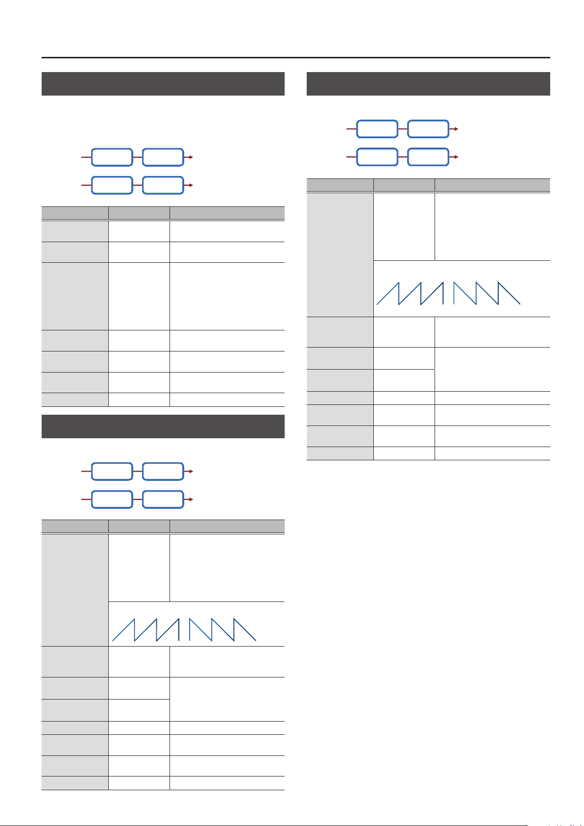
MFX/IFX Parameters
Ring Mod (Ring Modulator)
This is an eect that applies amplitude modulation (AM) to the input
signal, producing bell-like sounds. You can also change the modulation
frequency in response to changes in the volume of the sound sent into
the eect.
L in L out
Ring Mod 2-Band EQ
Ring Mod 2-Band EQ
R outR in
Parameter Value Explanation
Frequency
Sens
Polarity
Low Gain
High Gain
Balance
Level
0–127
0–127
UP, DOWN
-15–+15 [dB]
-15–+15 [dB]
D100: 0W–D0:
100W
0–127 Output Level
Adjusts the frequency at which
modulation is applied.
Adjusts the amount of frequency
modulation applied.
Determines whether the frequency
modulation moves towards higher
frequencies or lower frequencies.
UP: The lter will change toward a
higher frequency.
DOWN: The lter will change toward a
lower frequency.
Amount of boost/cut for the lowfrequency range
Amount of boost/cut for the highfrequency range
Volume balance between the direct
sound (D) and the eect sound (W)
Tremolo
Cyclically changes the volume.
Auto Pan
Cyclically modulates the stereo location of the sound.
L in L out
Parameter Value Explanation
Mod Wave
(Modulation Wave)
Rate Sync
(Rate (sync switch))
Rate
(Rate (Hz))
Rate Note
(Rate (note))
Depth
Low Gain
High Gain
Level
Auto Pan 2-Band EQ
Auto Pan 2-Band EQ
TRI, SQR, SIN,
SAW1, SAW2, TRP
SAW1 SAW2
R R
L L
OFF, ON
0.05–10.00 [Hz]
Note
& “Note” (p. 64)
0–127 Depth to which the eect is applied
-15–+15 [dB]
-15–+15 [dB]
0–127 Output Level
R outR in
Modulation Wave
TRI: Triangle wave
SQR: Square wave
SIN: Sine wave
SAW1/2: Sawtooth wave
TRP: Trapezoidal wave
If this is ON, the rate synchronizes with
the tempo of the rhythm.
& “Tempo” (p. 16)
Frequency of the change
Amount of boost/cut for the lowfrequency range
Amount of boost/cut for the highfrequency range
L in L out
Tremolo 2-Band EQ
Tremolo 2-Band EQ
R outR in
Parameter Value Explanation
Modulation Wave
TRI: Triangle wave
SQR: Square wave
SIN: Sine wave
SAW1/2: Sawtooth wave
TRP: Trapezoidal wave
If this is ON, the rate synchronizes with
the tempo of the rhythm.
& “Tempo” (p. 16)
Frequency of the change
Amount of boost/cut for the lowfrequency range
Amount of boost/cut for the highfrequency range
Mod Wave
(Modulation Wave)
Rate Sync
(Rate (sync switch))
Rate
(Rate (Hz))
Rate Note
(Rate (note))
Depth
Low Gain
High Gain
Level
TRI, SQR, SIN,
SAW1, SAW2, TRP
SAW1 SAW2
OFF, ON
0.05–10.00 [Hz]
Note
& “Note” (p. 64)
0–127 Depth to which the eect is applied
-15–+15 [dB]
-15–+15 [dB]
0–127 Output Level
27
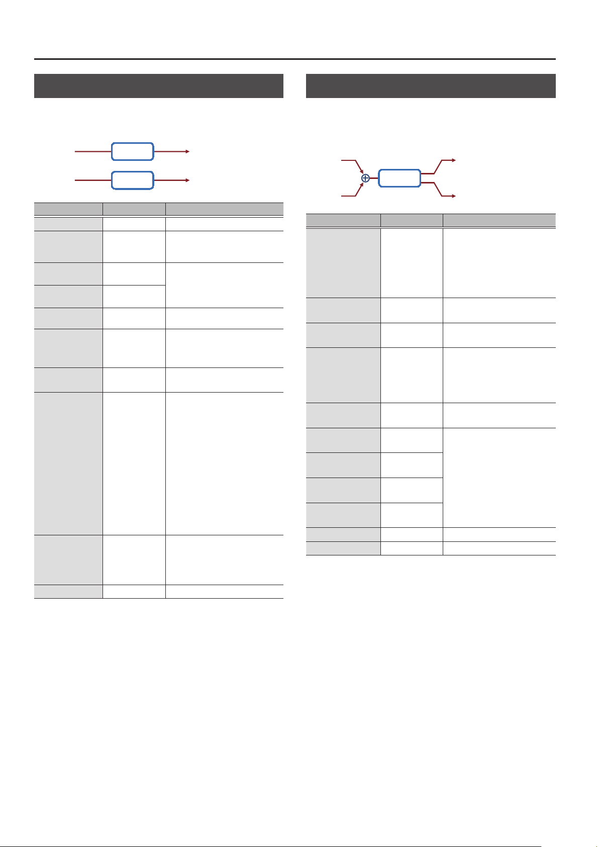
MFX/IFX Parameters
Slicer
By applying successive cuts to the sound, this eect turns a conventional
sound into a sound that appears to be played as a backing phrase. This is
especially eective when applied to sustain-type sounds.
L in L out
Parameter Value Explanation
Step 1–16
Rate Sync
(Rate (sync switch))
Rate
(Rate (Hz))
Rate Note
(Rate (note))
Attack
In Sync Sw
(Input Sync Sw)
IInSyncThres
(Input Sync Threshold)
Mode
Shue
Level
Slicer
Slicer
0–127 Level at each step
OFF, ON
0.05–10.00 [Hz]
Note
& “Note” (p. 64)
0–127
OFF, ON
0–127
LEGATO, SLASH
0–127
0–127 Output Level
R outR in
If this is ON, the rate synchronizes with
the tempo of the rhythm.
& “Tempo” (p. 16)
Rate at which the 16-step sequence
will cycle
Speed at which the level changes
between steps
Species whether an input note will
cause the sequence to resume from
the rst step of the sequence (ON) or
not (OFF)
Volume at which an input note will be
detected
Sets the manner in which the volume
changes as one step progresses to
the next.
LEGATO: The change in volume from
one step’s level to the next remains
unaltered.
If the level of a following step is the
same as the one preceding it, there is
no change in volume.
SLASH: The level is momentarily set
to 0 before progressing to the level of
the next step.
This change in volume occurs even if
the level of the following step is the
same as the preceding step.
Timing of volume changes in levels
for even numbered steps (step 2, step
4, step 6...).
The higher the value, the later the
beat progresses.
Rotary
This simulates a classic rotary speaker of the past.
Since the operation of the high-frequency and low-frequency rotors can
be specied independently, the distinctive modulation can be reproduced
realistically. This is most eective on organ patches.
L in
Rotary
R in
Parameter Value Explanation
Speed
Wf Slow
(Woofer Slow Speed)
Wf Fast
(Woofer Fast Speed)
Wf Accel
(Woofer Acceleration)
Wf Level
(Woofer Level)
Tw Slow
(Tweeter Slow Speed)
Tw Fast
(Tweeter Fast Speed)
Tw Accel
(Tweeter Acceleration)
Tw Level
(Tweeter Level)
Separation
Level
SLOW, FAST
0.05–10.00 [Hz]
0.05–10.00 [Hz]
0–15
0–127 Volume of the low frequency rotor
0.05–10.00 [Hz]
0.05–10.00 [Hz]
0–15
0–127
0–127 Spatial dispersion of the sound
0–127 Output Level
L out
R out
Simultaneously switch the rotational
speed of the low frequency rotor
and high frequency rotor.
SLOW: Slows down the rotation to
the Slow Rate.
FAST: Speeds up the rotation to the
Fast Rate.
Slow speed (SLOW) of the low
frequency rotor
Fast speed (FAST) of the low
frequency rotor
Adjusts the time it takes the low
frequency rotor to reach the newly
selected speed when switching
from fast to slow (or slow to fast)
speed. Lower values will require
longer times.
Settings of the high frequency rotor
The parameters are the same as for
the low frequency rotor
28
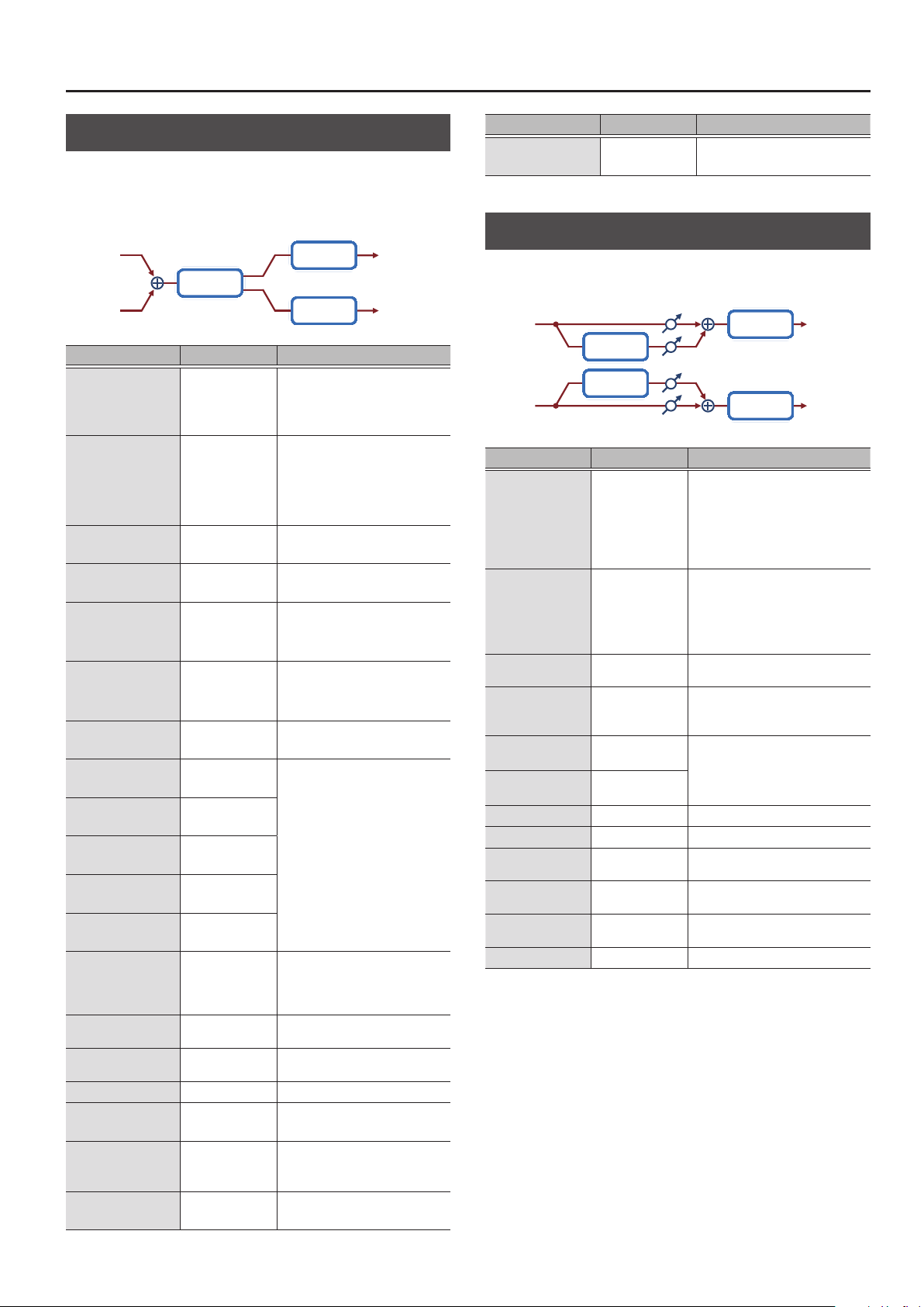
MFX/IFX Parameters
VK Rotary
This type provides modied response for the rotary speaker, with the low
end boosted further.
This eect features the same specications as the VK-7’s built-in rotary
speaker.
L in
Rotary
R in
2-Band EQ
2-Band EQ
Parameter Value Explanation
Rotational speed of the rotating
Speed
Brake
Wf Slow
(Woofer Slow Speed)
Wf Fast
(Woofer Fast Speed)
Wf Trs Up
(Woofer Trans Up)
Wf Trs Dw
(Woofer Trans Down)
Wf Level
(Woofer Level)
Tw Slow
(Tweeter Slow Speed)
Tw Fast
(Tweeter Fast Speed)
Tw Trs Up
(Tweeter Trans Up)
Tw Trs Dw
(Tweeter Trans Down)
Tw Level
(Tweeter Level)
Spread
Low Gain
High Gain
Level
OD Switch
(Overdrive Switch)
OD Gain
(Overdrive Gain)
OD Drive
(Overdrive Drive)
SLOW, FAST
OFF, ON
0.05–10.00 [Hz]
0.05–10.00 [Hz]
0–127
0–127
0–127 Volume of the woofer
0.05–10.00 [Hz]
0.05–10.00 [Hz]
0–127
0–127
0–127
0–10
-15–+15 [dB]
-15–+15 [dB]
0–127 Output Level
OFF, ON Overdrive on/o
0–127
0–127 Degree of distortion
speaker
SLOW: Slow
FAST: Fast
Switches the rotation of the rotary
speaker.
When this is turned on, the rotation
will gradually stop. When it is turned
o, the rotation will gradually
resume.
Low-speed rotation speed of the
woofer
High-speed rotation speed of the
woofer
Adjusts the rate at which the
woofer rotation speeds up when
the rotation is switched from Slow
to Fast.
Adjusts the rate at which the
woofer rotation speeds up when
the rotation is switched from Fast
to Slow.
Settings of the tweeter
The parameters are the same as for
the woofer.
Sets the rotary speaker stereo
image.
?The higher the value set, the wider
the sound is spread out.
Amount of boost/cut for the lowfrequency range
Amount of boost/cut for the highfrequency range
Overdrive input level
Higher values will increase the
distortion.
L out
R out
Parameter Value Explanation
OD Level
(Overdrive Level)
0–127 Volume of the overdrive
Chorus
This is a stereo chorus. A lter is provided so that you can adjust the
timbre of the chorus sound.
Balance D
L in
R in
Chorus
Chorus
Balance W
Balance W
Balance D
2-Band EQ
2-Band EQ
Parameter Value Explanation
Type of lter
OFF: No lter is used
Type
Cuto
(Cuto Freq)
Pre Delay
Rate Sync
(Rate (sync switch))
Rate
(Rate (Hz))
Rate Note
(Rate (note))
Depth
Phase
Low Gain
High Gain
Balance
Level
OFF, LPF, HPF
200, 250, 315, 400,
500, 630, 800,
1000, 1250, 1600,
2000, 2500, 3150,
4000, 5000, 6300,
8000 [Hz]
0.0–100 [msec]
OFF, ON
0.05–10.00 [Hz]
Note
& “Note” (p. 64)
0–127 Depth of modulation
0–180 [deg] Spatial spread of the sound
-15–+15 [dB]
-15–+15 [dB]
D100: 0W–D0:
100W
0–127 Output Level
LPF: Cuts the frequency range above
the Cuto Freq
HPF: Cuts the frequency range below
the Cuto Freq
Basic frequency of the lter
Adjusts the delay time from the direct
sound until the chorus sound is heard.
If this is ON, the rate synchronizes with
the tempo of the rhythm.
& “Tempo” (p. 16)
Frequency of modulation
Amount of boost/cut for the lowfrequency range
Amount of boost/cut for the highfrequency range
Volume balance between the direct
sound (D) and the chorus sound (W)
L out
R out
29

MFX/IFX Parameters
Flanger
This is a stereo anger (The LFO has the same phase for left and right.).
Produces a metallic resonance reminiscent of a jet airplane taking o and
landing.
A lter is provided so that you can adjust the timbre of the anged sound.
Balance D
Balance W
Balance W
2-Band EQ
2-Band EQ
L out
R out
L in
Flanger
Feedback
Feedback
Flanger
R in
Balance D
Parameter Value Explanation
Type of lter
OFF: No lter is used
Type
Cuto
(Cuto Freq)
Pre Delay
Rate Sync
(Rate (sync switch))
Rate
(Rate (Hz))
Rate Note
(Rate (note))
Depth
Phase
Feedback
Low Gain
High Gain
Balance
Level
OFF, LPF, HPF
200, 250, 315, 400,
500, 630, 800,
1000, 1250, 1600,
2000, 2500, 3150,
4000, 5000, 6300,
8000 [Hz]
0.0–100 [msec]
OFF, ON
0.05–10.00 [Hz]
Note
& “Note” (p. 64)
0–127 Depth of modulation
0–180 [deg] Spatial spread of the sound
-98–+98 [%]
-15–+15 [dB]
-15–+15 [dB]
D100: 0W–D0:
100W
0–127 Output Level
LPF: Cuts the frequency range above
the Cuto Freq
HPF: Cuts the frequency range below
the Cuto Freq
Basic frequency of the lter
Adjusts the delay time from when the
direct sound begins until the anger
sound is heard.
If this is ON, the rate synchronizes with
the tempo of the rhythm.
& “Tempo” (p. 16)
Frequency of modulation
Adjusts the proportion of the anger
sound that is fed back into the eect.
Negative (-) settings will invert the
phase.
Amount of boost/cut for the lowfrequency range
Amount of boost/cut for the highfrequency range
Volume balance between the direct
sound (D) and the anger sound (W)
StepFlanger
This is a anger in which the anger pitch changes in steps. The speed at
which the pitch changes can also be specied in terms of a note-value of
a specied tempo.
Balance D
Balance W
Balance W
2-Band EQ
2-Band EQ
L out
R out
L in
Step
Flanger
Feedback
Feedback
Step
Flanger
R in
Balance D
Parameter Value Explanation
Type of lter
OFF: No lter is used
Type
Cuto
(Cuto Freq)
Pre Delay
Rate Sync
(Rate (sync switch))
Rate
(Rate (Hz))
Rate Note
(Rate (note))
Depth
Phase
Feedback
S. Rate Sync
(Step Rate
(sync switch))
S. Rate
(Step Rate (Hz))
S. Rate Nt
(Step Rate (note))
Low Gain
High Gain
Balance
Level
OFF, LPF, HPF
200, 250, 315, 400,
500, 630, 800,
1000, 1250, 1600,
2000, 2500, 3150,
4000, 5000, 6300,
8000 [Hz]
0.0–100.0 [msec]
OFF, ON
0.05–10.00 [Hz]
Note
& “Note” (p. 64)
0–127 Depth of modulation
0–180 [deg] Spatial spread of the sound
-98–+98 [%]
OFF, ON
0.10–20.00 [Hz]
Note
& “Note” (p. 64)
-15–+15 [dB]
-15–+15 [dB]
D100: 0W–D0:
100W
0–127 Output Level
LPF: Cuts the frequency range above
the Cuto Freq
HPF: Cuts the frequency range below
the Cuto Freq
Basic frequency of the lter
Adjusts the delay time from when the
direct sound begins until the anger
sound is heard.
If this is ON, the rate synchronizes with
the tempo of the rhythm.
& “Tempo” (p. 16)
Frequency of modulation
Adjusts the proportion of the anger
sound that is fed back into the eect.
Negative (-) settings will invert the
phase.
If this is ON, the rate synchronizes with
the tempo of the rhythm.
& “Tempo” (p. 16)
Rate (period) of pitch change
Amount of boost/cut for the lowfrequency range
Amount of boost/cut for the highfrequency range
Volume balance between the direct
sound (D) and the anger sound (W)
30

MFX/IFX Parameters
Hexa-Chorus
Uses a six-phase chorus (six layers of chorused sound) to give richness and
spatial spread to the sound.
Balance D
L in
Hexa
Chorus
R in
Balance D
Parameter Value Explanation
Pre Delay
Rate Sync
(Rate (sync switch))
Rate
(Rate (Hz))
Rate Note
(Rate (note))
Depth
PreDly Dev
(Pre Delay Deviation)
Depth Dev
(Depth Deviation)
Pan Dev
(Pan Deviation)
Balance
Level
0.0–100 [msec]
OFF, ON
0.05–10.00 [Hz]
Note
& “Note” (p. 64)
0–127 Depth of modulation
0–20
-20–+20
0–20
D100: 0W–D0:
100W
0–127 Output Level
L out
Balance W
Balance W
R out
Adjusts the delay time from the direct
sound until the chorus sound is heard.
If this is ON, the rate synchronizes with
the tempo of the rhythm.
& “Tempo” (p. 16)
Frequency of modulation
Adjusts the dierences in Pre Delay
between each chorus sound.
Adjusts the dierence in modulation
depth between each chorus sound.
Adjusts the dierence in stereo
location between each chorus sound.
0: All chorus sounds will be in the
center.
20: Each chorus sound will be spaced
at 60 degree intervals relative to the
center.
Volume balance between the direct
sound (D) and the chorus sound (W)
Trem Chorus (Tremolo Chorus)
This is a chorus eect with added Tremolo (cyclic modulation of volume).
Balance D
L in
Tremolo
Chorus
R in
Balance D
Parameter Value Explanation
Pre Delay
Cho Sync
(Chorus Rate
(sync switch))
C. Rate
(Chorus Rate (Hz))
C. Rate Nt
(Chorus Rate (note))
Cho Depth
(Chorus Depth)
Trm Sync
(Tremolo Rate
(sync switch))
T. Rate
(Tremolo Rate (Hz))
T. Rate Nt
(Tremolo Rate (note))
Trm Separate
(Tremolo Separation)
Trm Phase
(Tremolo Phase)
Balance
Level
0.0–100 [msec]
OFF, ON
0.05–10.00 [Hz]
Note
& “Note” (p. 64)
0–127
OFF, ON
0.05–10.00 [Hz]
Note
& “Note” (p. 64)
0–127 Spread of the tremolo eect
0–180 [deg] Spread of the tremolo eect
D100: 0W–D0:
100W
0–127 Output Level
L out
Balance W
Balance W
R out
Adjusts the delay time from the
direct sound until the chorus sound
is heard.
If this is ON, the rate synchronizes
with the tempo of the rhythm.
& “Tempo” (p. 16)
Modulation frequency of the chorus
eect
Modulation depth of the chorus
eect
If this is ON, the rate synchronizes
with the tempo of the rhythm.
& “Tempo” (p. 16)
Modulation frequency of the
tremolo eect
Volume balance between the direct
sound (D) and the chorus sound (W)
31

MFX/IFX Parameters
Space-D
This is a multiple chorus that applies two-phase modulation in stereo. It
gives no impression of modulation, but produces a transparent chorus
eect.
Balance D
L in
R in
Space D
Space D
Balance W
Balance W
Balance D
2-Band EQ
2-Band EQ
Parameter Value Explanation
Pre Delay
Rate Sync
(Rate (sync switch))
Rate
(Rate (Hz))
Rate Note
(Rate (note))
Depth
Phase
Low Gain
High Gain
Balance
Level
0.0–100 [msec]
OFF, ON
0.05–10.00 [Hz]
Note
& “Note” (p. 64)
0–127 Depth of modulation
0–180 [deg] Spatial spread of the sound
-15–+15 [dB]
-15–+15 [dB]
D100: 0W–D0:
100W
0–127 Output Level
Adjusts the delay time from the direct
sound until the chorus sound is heard.
If this is ON, the rate synchronizes with
the tempo of the rhythm.
& “Tempo” (p. 16)
Frequency of modulation
Amount of boost/cut for the lowfrequency range
Amount of boost/cut for the highfrequency range
Volume balance between the direct
sound (D) and the chorus sound (W)
L out
R out
Distortion
Produces a more intense distortion than Overdrive.
L in
Distortion 2-Band EQ
Amp
Smlator
Pan L
Pan R
R in
Parameter Value Explanation
Drive
Tone
Amp Switch
Amp Type
(Amp Type)
Low Gain
High Gain
Pan
Level
0–127
0–127 Sound quality of the Overdrive eect
OFF, ON Turns the Amp Simulator on/o.
SMALL,
BUILT-IN, 2-STACK,
3-STACK
-15–+15 [dB]
-15–+15 [dB]
L64–63R Stereo location of the output sound
0–127 Output Level
Degree of distortion
Also changes the volume.
Type of guitar amp
SMALL: Small amp
BUILT-IN: Single-unit type amp
2-STACK: Large double stack amp
3-STACK: Large triple stack amp
Amount of boost/cut for the lowfrequency range
Amount of boost/cut for the highfrequency range
T-Scream
This models a classic analog overdrive. It is distinctive in adding an
appropriate amount of overtones without muddying the sound.
L out
R out
Overdrive
This is an overdrive that provides heavy distortion.
L in
Overdrive 2-Band EQ
R in
Parameter Value Explanation
Drive
Tone
Amp Switch
Amp Type
(Amp Type)
Low Gain
High Gain
Pan
Level
0–127
0–127 Sound quality of the Overdrive eect
OFF, ON Turns the Amp Simulator on/o.
SMALL,
BUILT-IN, 2-STACK,
3-STACK
-15–+15 [dB]
-15–+15 [dB]
L64–63R Stereo location of the output sound
0–127 Output Level
Amp
Smlator
Degree of distortion
Also changes the volume.
Type of guitar amp
SMALL: Small amp
BUILT-IN: Single-unit type amp
2-STACK: Large double stack amp
3-STACK: Large triple stack amp
Amount of boost/cut for the lowfrequency range
Amount of boost/cut for the highfrequency range
Pan L
Pan R
L out
R out
L in L out
Overdrive
Overdrive
Tone
Tone
Parameter Value Explanation
Distortion
Tone
Level
0–127
0–127 Tonal character of the overdrive
0–127 Output Level
Degree of distortion
Also changes the volume.
R outR in
32

MFX/IFX Parameters
Gt Amp Sim (Guitar Amp Simulator)
This is an eect that simulates the sound of a guitar amplier.
L in
SpeakerPre Amp
R in
Parameter Value Explanation
Pre Amp Sw
(Pre Amp Switch)
OFF, ON Turns the amp switch on/o.
Type of guitar amp
This models the sound of the Roland
JC-120.
This models the sound input to left
input on a Matchless D/C-30.
A simulation of the latest tube amp
widely used in styles from blues and
rock.
This models the lead sound of the
MESA/ Boogie combo amp.
The sound of a tube amp typical of the
late ‘70s to ‘80s.
This models the sound input to Input I
on a Marshall 1959.
This is a trebly sound suited to hard
rock.
This models the sound input to Input II
on a Marshall 1959.
The sound of connecting inputs I and II
of the guitar amp in parallel, creating a
sound with a stronger low end than I.
This models a Soldano SLO-100. This is
the typical sound of the eighties.
This models the lead channel of a
Peavey EVH 5150.
This is distortion sound that is ideal for
performances of heavy ris.
This models the sound of the BOSS
OD-1.
This produces sweet, mild distortion.
This is the high-gain overdrive sound of
the BOSS OD-2.
This gives a basic, traditional distortion
sound.
A fuzz sound with rich harmonic
content.
Volume and amount of distortion of
the amp
Amount of pre-amp distortion
AmpType
(Pre Amp Type)
Drive
(Pre Amp Drive)
Master Lv
(Pre Amp Master)
Gain
(Pre Amp Gain)
JC-120
CLEAN TWIN This models a Fender Twin Reverb.
MATCH DRIVE
BG LEAD
MS1959I
MS1959II
MS1959I+II
SLDN LEAD
METAL 5150
METAL LEAD
OD-1
OD-2 TURBO
DISTORTION
FUZZ
0–127
0–127 Volume of the entire pre-amp
LOW, MIDDLE,
HIGH
Bass
(Pre Amp Bass)
Middle
(Pre Amp Middle)
Treble
(Pre Amp Treble)
Presence
(Pre Amp Presence)
0–127
0–127 Tone for the ultra-high frequency range
Tone of the bass/mid/treble frequency
range
Middle cannot be set if “MATCH
DRIVE” is selected as the Pre Amp Type.
Pan L
Pan R
L out
R out
Parameter Value Explanation
Turning this “On” produces a sharper
Bright
(Pre Amp Bright)
Speaker Sw
(Speaker Switch)
SpType
(Speaker Type)
Mic Setting
Mic Level
Direct Level
Pan
Level
OFF, ON
OFF, ON
SMALL 1
SMALL 2
MIDDLE
JC-120
BUILT-IN 1
BUILT-IN 2
BUILT-IN 3
BUILT-IN 4
BUILT-IN 5
BG STACK1
BG STACK2
MS STACK1
MS STACK2
MTL STACK
2-STACK
3-STACK
1, 2, 3
0–127 Volume of the microphone
0–127 Volume of the direct sound
L64–63R Stereo location of the output sound
0–127 Output Level
and brighter sound.
* This parameter applies to the “JC-
120,” “CLEAN TWIN,” and “BG LEAD”
Pre Amp Types.
Selects whether the sound will be sent
through the speaker simulation (ON) or
not (OFF)
Cabinet
small
open-back
enclosure
small
open-back
enclosure
open back
enclosure
open back
enclosure
open back
enclosure
open back
enclosure
open back
enclosure
open back
enclosure
open back
enclosure
sealed
enclosure
large sealed
enclosure
large sealed
enclosure
large sealed
enclosure
large
double
stack
large
double
stack
large triple
stack
Adjusts the location of the mic that is
recording the sound of the speaker.
This can be adjusted in three steps, with
the mic becoming more distant in the
order of 1, 2, and 3.
Diameter
(in inches)
and
number of
the speaker
12 x 1 dynamic
12 x 2 dynamic
12 x 2 dynamic
12 x 2 condenser
12 x 2 condenser
12 x 2 condenser
12 x 2 condenser
12 x 2 condenser
12 x 2 condenser
12 x 4 condenser
12 x 4 condenser
12 x 4 condenser
12 x 4 condenser
12 x 4 condenser
Microphone
10 dynamic
10 dynamic
33

MFX/IFX Parameters
Compressor
Flattens out high levels and boosts low levels, smoothing out uctuations
in volume.
L in L out
Parameter Value Explanation
Attack
Release
Threshold
Knee
Ratio
Post Gain
Level
Compressor 2-Band EQ
Compressor 2-Band EQ
0–124
0–124
-60–0 [dB]
0–30 [dB]
1: 1, 1.5: 1, 2: 1, 4: 1,
16: 1, INF: 1
0–+18 [dB] Adjusts the output gain.
0–127 Output Level
Sets the speed at which compression
starts
Adjusts the time after the signal volume
falls below the Threshold Level until
compression is no longer applied.
Adjusts the volume at which compression
begins
This is a function that smooths the onset
of compression from the uncompressed
state; it gradually applies compression
starting earlier than Threshold. Higher
values produce a smoother transition.
Compression ratio
R outR in
Sustainer
By compressing loud input and boosting low input, this eect keeps the
volume consistent to produce a sustain eect without distortion.
L in L out
Sustainer 2-Band EQ
Sustainer 2-Band EQ
R outR in
Parameter Value Explanation
Adjusts the range in which a low input
Sustain
Attack
Release
Post Gain
Low Gain
High Gain
Level
0–127
0–127 Time until the volume is compressed
0–127 Time until compression is removed
-15–+15 [dB] Adjusts the output gain.
-15–+15 [dB]
-15–+15 [dB]
0–127 Output Level
signal is boosted to a consistent volume.
Higher values produce longer sustain.
Amount of boost/cut for the lowfrequency range
Amount of boost/cut for the highfrequency range
Gate
Limiter
Compresses signals that exceed a specied volume level, preventing
distortion from occurring.
L in L out
Parameter Value Explanation
Release
Threshold
Ratio
Post Gain
Low Gain
High Gain
Level
Limiter 2-Band EQ
Limiter 2-Band EQ
0–127
0–127
1.5: 1, 2: 1, 4: 1,
100: 1
0–+18 [dB] Adjusts the output gain.
-15–+15 [dB]
-15–+15 [dB]
0–127 Output Level
Adjusts the time after the signal volume
falls below the Threshold Level until
compression is no longer applied.
Adjusts the volume at which compression
begins
Compression ratio
Amount of boost/cut for the low-frequency
range
Amount of boost/cut for the high-frequency
range
R outR in
Cuts the reverb’s delay according to the volume of the sound sent into the
eect. Use this when you want to create an articial-sounding decrease in
the reverb’s decay.
L in L out
Gate
Gate
R outR in
Parameter Value Explanation
Threshold
Mode
Attack
Hold
Release
Balance
Level
0–127
GATE, DUCK
0–127
0–127
0–127
D100: 0W–D0:
100W
0–127 Output Level
Volume level at which the gate begins
to close
Type of gate
GATE: The gate will close when the
volume of the original sound decreases,
cutting the original sound.
DUCK (Duking): The gate will close
when the volume of the original sound
increases, cutting the original sound.
Adjusts the time it takes for the gate to
fully open after being triggered.
Adjusts the time it takes for the gate to
start closing after the source sound falls
beneath the Threshold.
Adjusts the time it takes the gate to fully
close after the hold time.
Volume balance between the direct sound
(D) and the eect sound (W)
34
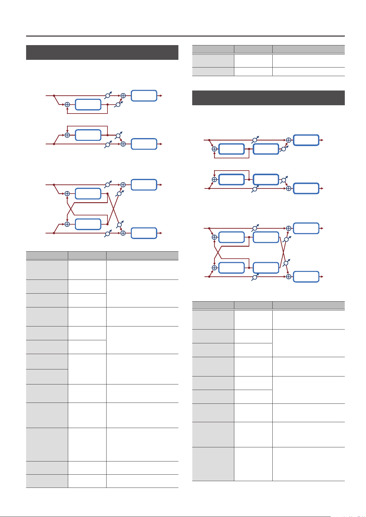
MFX/IFX Parameters
Delay
This is a stereo delay.
When Feedback Mode is NORMAL:
Balance D
L in
Delay
Feedback
Feedback
Delay
R in
Balance D
When Feedback Mode is CROSS:
Balance D
L in
Delay
Feedback
Feedback
Delay
R in
Balance D
Parameter Value Explanation
Dly L Sync
(Delay Left
(sync switch))
DL. Time
(Delay Left (msec))
DLTime Nt
(Delay Left (note))
Dly R Sync
(Delay Right
(sync switch))
DR. Time
(Delay Right (msec))
DRTime Nt
(Delay Right (note))
Phase L
(Phase Left)
Phase R
(Phase Right)
Fbk Mode
(Feedback Mode)
Feedback
HF Damp
Low Gain
High Gain
OFF, ON
1–1300
Note
& “Note” (p. 64)
OFF, ON
1–1300
Note
& “Note” (p. 64)
NORMAL, INVERSE
NORMAL, CROSS
-98–+98 [%]
200, 250, 315, 400,
500, 630, 800,
1000, 1250, 1600,
2000, 2500, 3150,
4000, 5000, 6300,
8000, BYPASS [Hz]
-15–+15 [dB]
-15–+15 [dB]
Balance W
Balance W
Balance W
Balance W
If this is ON, the rate synchronizes with
the tempo of the rhythm.
& “Tempo” (p. 16)
Adjusts the time until the left delay
sound is heard.
If this is ON, the rate synchronizes with
the tempo of the rhythm.
& “Tempo” (p. 16)
Adjusts the time until the right delay
sound is heard.
Phase of left and right delay sound
NORMAL: Non-inverted
INVERT: Inverted
Selects the way in which delay sound
is fed back into the eect. (See the
gures above.)
Adjusts the proportion of the delay
sound that is fed back into the eect.
Negative (-) settings will invert the
phase.
Adjusts the frequency above which
sound fed back to the eect is ltered
out. If you don’t want to lter out any
high frequencies, set this parameter
to BYPASS.
Amount of boost/cut for the lowfrequency range
Amount of boost/cut for the highfrequency range
2-Band EQ
2-Band EQ
2-Band EQ
2-Band EQ
L out
R out
L out
R out
Parameter Value Explanation
Balance
Level
D100: 0W–D0:
100W
0–127 Output Level
Volume balance between the direct
sound (D) and the delay sound (W)
Mod Delay (Modulation Delay)
Adds modulation to the delayed sound.
When Feedback Mode is NORMAL:
Balance D
L in
Delay Modulation
Feedback
Feedback
Delay Modulation
R in
Balance D
When Feedback Mode is CROSS:
Balance D
L in
Delay
Feedback
Feedback
Delay Modulation
R in
Parameter Value Explanation
Dly L Sync
(Delay Left
(sync switch))
DL. Time
(Delay Left (msec))
DLTime Nt
(Delay Left (note))
Dly R Sync
(Delay Right
(sync switch))
DR. Time
(Delay Right (msec))
DRTime Nt
(Delay Right (note))
Fbk Mode
(Feedback Mode)
Feedback
HF Damp
OFF, ON
1–1300
Note
& “Note” (p. 64)
OFF, ON
1–1300
Note
& “Note” (p. 64)
NORMAL, CROSS
-98–+98 [%]
200, 250, 315, 400,
500, 630, 800,
1000, 1250, 1600,
2000, 2500, 3150,
4000, 5000, 6300,
8000, BYPASS [Hz]
Modulation
Balance D
If this is ON, the rate synchronizes with
the tempo of the rhythm.
& “Tempo” (p. 16)
Adjusts the time until the left delay
sound is heard.
If this is ON, the rate synchronizes with
the tempo of the rhythm.
& “Tempo” (p. 16)
Adjusts the time until the right delay
sound is heard.
Selects the way in which delay sound
is fed back into the eect. (See the
gures above.)
Adjusts the proportion of the delay
sound that is fed back into the eect.
Negative (-) settings will invert the
phase.
Adjusts the frequency above which
sound fed back to the eect is ltered
out. If you don’t want to lter out any
high frequencies, set this parameter
to BYPASS.
2-Band EQ
Balance W
Balance W
2-Band EQ
2-Band EQ
Balance W
Balance W
2-Band EQ
L out
R out
L out
R out
35

MFX/IFX Parameters
Parameter Value Explanation
Rate Sync
(Rate (sync switch))
Rate
(Rate (Hz))
Rate Note
(Rate (note))
Depth
Phase
Low Gain
High Gain
Balance
Level
OFF, ON
0.05–10.00 [Hz]
Note
& “Note” (p. 64)
0–127 Depth of modulation
0–180 [deg] Spatial spread of the sound
-15–+15 [dB]
-15–+15 [dB]
D100: 0W–D0:
100W
0–127 Output Level
If this is ON, the rate synchronizes with
the tempo of the rhythm.
& “Tempo” (p. 16)
Frequency of modulation
Amount of boost/cut for the lowfrequency range
Amount of boost/cut for the highfrequency range
Volume balance between the direct
sound (D) and the delay sound (W)
3Tap PanDly
Produces three delay sounds; center, left and right.
Balance D
L in
Left Tap
Triple Tap
Feedback
Delay
Center Tap
Right Tap
R in
Balance D
Parameter Value Explanation
Dly L Sync
(Delay Left (sync switch))
DL. Time
(Delay Left (msec))
DLTime Nt
(Delay Left (note))
Dly R Sync
(Delay Right (sync switch))
DR. Time
(Delay Right (msec))
DRTime Nt
(Delay Right (note))
Dly C Sync
(Delay Center
(sync switch))
DC. Time
(Delay Center (msec))
DCTime Nt
(Delay Center (note))
C Feedback
(Center Feedback)
HF Damp
Left Lv
Right Lv
Center Lv
Low Gain
High Gain
Balance
Level
OFF, ON
1–2600
Note
& “Note” (p. 64)
OFF, ON
1–2600
Note
& “Note” (p. 64)
OFF, ON
1–2600
Note
& “Note” (p. 64)
-98–+98 [%]
200, 250, 315, 400,
500, 630, 800,
1000, 1250, 1600,
2000, 2500, 3150,
4000, 5000, 6300,
8000, BYPASS [Hz]
0–127
0–127
0–127
-15–+15 [dB]
-15–+15 [dB]
D100: 0W–D0:
100W
0–127 Output Level
2-Band EQ
Balance W
Balance W
2-Band EQ
If this is ON, the rate synchronizes
with the tempo of the rhythm.
& “Tempo” (p. 16)
Adjusts the time until the left delay
sound is heard.
If this is ON, the rate synchronizes
with the tempo of the rhythm.
& “Tempo” (p. 16)
Adjusts the time until the right delay
sound is heard.
If this is ON, the rate synchronizes
with the tempo of the rhythm.
& “Tempo” (p. 16)
Adjusts the time until the center
delay sound is heard.
Adjusts the proportion of the delay
sound that is fed back into the
eect.
Negative (-) settings will invert the
phase.
Adjusts the frequency above which
sound fed back to the eect is
ltered out. If you don’t want to
lter out any high frequencies, set
this parameter to BYPASS.
Volume of each delay sound
Amount of boost/cut for the lowfrequency range
Amount of boost/cut for the highfrequency range
Volume balance between the direct
sound (D) and the delay sound (W)
L out
R out
36

MFX/IFX Parameters
4Tap PanDly
This eect has four delays.
Balance D
L in
Feedback
Quadruple
Tap Delay
R in
2 3
1
L
Parameter Value Explanation
Dly1 Sync
(Delay 1 Time
(sync switch))
D1. Time
(Delay 1 Time (msec))
D1Time Nt
(Delay 1 Time (note))
Dly2 Sync
(Delay 2 Time
(sync switch))
D2. Time
(Delay 2 Time (msec))
D2Time Nt
(Delay 2 Time (note))
Dly3 Sync
(Delay 3 Time
(sync switch))
D3. Time
(Delay 3 Time (msec))
D3Time Nt
(Delay 3 Time (note))
Dly4 Sync
(Delay 4 Time
(sync switch))
D4. Time
(Delay 4 Time (msec))
D4Time Nt
(Delay 4 Time (note))
Dly1 Fbk
(Delay 1 Feedback)
HF Damp
Dly1 Lv
(Delay 1 Level)
Dly2 Lv
(Delay 2 Level)
Dly3 Lv
(Delay 3 Level)
Dly4 Lv
(Delay 4 Level)
Delay 1
Delay 2
Delay 3
Delay 4
Balance D
4
R
If this is ON, the rate synchronizes
OFF, ON
1–2600
Note
& “Note” (p. 64)
OFF, ON
1–2600
Note
& “Note” (p. 64)
OFF, ON
1–2600
Note
& “Note” (p. 64)
OFF, ON
1–2600
Note
& “Note” (p. 64)
-98–+98 [%]
200, 250, 315, 400,
500, 630, 800,
1000, 1250, 1600,
2000, 2500, 3150,
4000, 5000, 6300,
8000, BYPASS [Hz]
0–127 Volume of each delay
with the tempo of the rhythm.
& “Tempo” (p. 16)
Adjusts the time from the original
sound until delay 1 sounds is heard.
If this is ON, the rate synchronizes
with the tempo of the rhythm.
& “Tempo” (p. 16)
Adjusts the time from the original
sound until delay 2 sounds is heard.
If this is ON, the rate synchronizes
with the tempo of the rhythm.
& “Tempo” (p. 16)
Adjusts the time from the original
sound until delay 3 sounds is heard.
If this is ON, the rate synchronizes
with the tempo of the rhythm.
& “Tempo” (p. 16)
Adjusts the time from the original
sound until delay 4 sounds is heard.
Adjusts the proportion of the delay
sound that is fed back into the
eect.
Negative (-) settings will invert the
phase.
Adjusts the frequency above which
sound fed back to the eect is
ltered out. If you don’t want to
lter out any high frequencies, set
this parameter to BYPASS.
Balance W
Balance W
L out
R out
Parameter Value Explanation
Low Gain
High Gain
Balance
Level
-15–+15 [dB]
-15–+15 [dB]
D100: 0W–D0:
100W
0–127 Output Level
Amount of boost/cut for the lowfrequency range
Amount of boost/cut for the highfrequency range
Volume balance between the direct
sound (D) and the delay sound (W)
37

MFX/IFX Parameters
MultiTapDly
This eect provides four delays. Each of the Delay Time parameters can
be set to a note length based on the selected tempo. You can also set the
panning and level of each delay sound.
Balance D
L in
Feedback
Delay 1
Delay 2
Multi Tap
Delay
Delay 3
Delay 4
R in
0
Balance D
Parameter Value Explanation
Dly1 Sync
(Delay 1 Time
(sync switch))
D1. Time
(Delay 1 Time (msec))
D1Time Nt
(Delay 1 Time (note))
Dly2 Sync
(Delay 2 Time
(sync switch))
D2. Time
(Delay 2 Time (msec))
D2Time Nt
(Delay 2 Time (note))
Dly3 Sync
(Delay 3 Time
(sync switch))
D3. Time
(Delay 3 Time (msec))
D3Time Nt
(Delay 3 Time (note))
Dly4 Sync
(Delay 4 Time
(sync switch))
D4. Time
(Delay 4 Time (msec))
D4Time Nt
(Delay 4 Time (note))
Dly1 Fbk
(Delay 1 Feedback)
HF Damp
OFF, ON
1–2600
Note
& “Note” (p. 64)
OFF, ON
1–2600
Note
& “Note” (p. 64)
OFF, ON
1–2600
Note
& “Note” (p. 64)
OFF, ON
1–2600
Note
& “Note” (p. 64)
-98–+98 [%]
200, 250, 315, 400,
500, 630, 800,
1000, 1250, 1600,
2000, 2500, 3150,
4000, 5000, 6300,
8000, BYPASS [Hz]
If this is ON, the rate synchronizes
with the tempo of the rhythm.
& “Tempo” (p. 16)
Adjusts the time from the original
sound until delay 1 sounds is heard.
If this is ON, the rate synchronizes
with the tempo of the rhythm.
& “Tempo” (p. 16)
Adjusts the time from the original
sound until delay 2 sounds is heard.
If this is ON, the rate synchronizes
with the tempo of the rhythm.
& “Tempo” (p. 16)
Adjusts the time from the original
sound until delay 3 sounds is heard.
If this is ON, the rate synchronizes
with the tempo of the rhythm.
& “Tempo” (p. 16)
Adjusts the time from the original
sound until delay 4 sounds is heard.
Adjusts the proportion of the delay
sound that is fed back into the
eect.
Negative (-) settings will invert the
phase.
Adjusts the frequency above which
sound fed back to the eect is
ltered out. If you don’t want to
lter out any high frequencies, set
this parameter to BYPASS.
Dly1 Pan
(Delay 1 Pan)
Dly2 Pan
(Delay 2 Pan)
Dly3 Pan
(Delay 3 Pan)
L64–63R Stereo location of Delays 1–4
Dly4 Pan
(Delay 4 Pan)
2-Band EQ
Balance W
Balance W
2-Band EQ
L out
R out
Parameter Value Explanation
Dly1 Level
(Delay 1 Level)
Dly2 Level
(Delay 2 Level)
Dly3 Level
(Delay 3 Level)
0–127 Volume of each delay
Dly4 Level
(Delay 4 Level)
Low Gain
High Gain
Balance
Level
-15–+15 [dB]
-15–+15 [dB]
D100: 0W–D0:
100W
0–127 Output Level
Amount of boost/cut for the lowfrequency range
Amount of boost/cut for the highfrequency range
Volume balance between the direct
sound (D) and the eect sound (W)
38

MFX/IFX Parameters
Reverse Dly
This is a reverse delay that adds a reversed and delayed sound to the input
sound. A tap delay is connected immediately after the reverse delay.
L in
Rev
D1
Rev. Delay
Feedback
Delay
D2D3
R in
Parameter Value Explanation
Threshold
RDly Sync
(Reverse Delay Time
(sync switch))
RD Time
(Reverse Delay Time
(msec))
RD. Time Nt
(Reverse Delay Time
(note))
RDly Fbk
(Reverse Delay Feedback)
RDly HF
(Reverse Delay HF Damp)
RDly Pan
(Reverse Delay Pan)
RDly Level
(Reverse Delay Level)
Dly1 Sync
(Delay 1 Time
(sync switch))
D1. Time
(Delay 1 Time (msec))
D1Time Nt
(Delay 1 Time (note))
Dly2 Sync
(Delay 2 Time
(sync switch))
D2. Time
(Delay 2 Time (msec))
D2Time Nt
(Delay 2 Time (note))
Dly3 Sync
(Delay 3 Time
(sync switch))
D3. Time
(Delay 3 Time (msec))
D3Time Nt
(Delay 3 Time (note))
Dly3 Fbk
(Delay 3 Feedback)
0–127
OFF, ON
1–1300
Note
& “Note” (p. 64)
-98–+98 [%]
200, 250, 315, 400,
500, 630, 800,
1000, 1250, 1600,
2000, 2500, 3150,
4000, 5000, 6300,
8000, BYPASS [Hz]
L64–63R Panning of the reverse delay sound
0–127 Volume of the reverse delay sound
OFF, ON
1–1300
Note
& “Note” (p. 64)
OFF, ON
1–1300
Note
& “Note” (p. 64)
OFF, ON
1–1300
Note
& “Note” (p. 64)
-98–+98 [%]
Volume at which the reverse delay
will begin to be applied
If this is ON, the rate synchronizes
with the tempo of the rhythm.
& “Tempo” (p. 16)
Delay time from when sound is
input into the reverse delay until the
delay sound is heard
Proportion of the delay sound that
is to be returned to the input of the
reverse delay negative (-) values
invert the phase
Frequency at which the highfrequency content of the
reverse-delayed sound will be cut
(BYPASS: no cut)
If this is ON, the rate synchronizes
with the tempo of the rhythm.
& “Tempo” (p. 16)
Delay time from when sound is
input into the tap delay until the
delay sound is heard
If this is ON, the rate synchronizes
with the tempo of the rhythm.
& “Tempo” (p. 16)
Delay time from when sound is
input into the tap delay until the
delay sound is heard
If this is ON, the rate synchronizes
with the tempo of the rhythm.
& “Tempo” (p. 16)
Delay time from when sound is
input into the tap delay until the
delay sound is heard
Proportion of the delay sound that
is to be returned to the input of the
tap delay (negative (-) values invert
the phase)
2-Band
EQ
2-Band
EQ
L out
R out
Parameter Value Explanation
200, 250, 315, 400,
Dly HF
(Delay HF Damp)
Dly1 Pan
(Delay 1 Pan)
Dly2 Pan
(Delay 2 Pan)
Dly1 Lv
(Delay 1 Level)
Dly2 Lv
(Delay 2 Level)
Low Gain
High Gain
Balance
Level
500, 630, 800,
1000, 1250, 1600,
2000, 2500, 3150,
4000, 5000, 6300,
8000, BYPASS [Hz]
L64–63R
L64–63R
0–127
0–127
-15–+15 [dB]
-15–+15 [dB]
D100: 0W–D0:
100W
0–127 Output Level
Frequency at which the hifrequency content of the tap delay
sound will be cut (BYPASS: no cut)
Panning of the tap delay sounds
Volume of the tap delay sounds
Amount of boost/cut for the lowfrequency range
Amount of boost/cut for the highfrequency range
Volume balance between the direct
sound (D) and the delay sound (W)
39

MFX/IFX Parameters
TimeCtrlDly (Time Control Delay)
A stereo delay in which the delay time can be varied smoothly.
Balance D
L in
Time Ctrl
Delay
Feedback
Feedback
Time Ctrl
Delay
R in
Balance D
Parameter Value Explanation
Delay Sync
(Delay Time
(sync switch))
D. Time
(Delay Time (msec))
D. Time Nt
(Delay Time (note))
Acceleration
Feedback
HF Damp
Low Gain
High Gain
Balance
Level
OFF, ON
1–1300
Note
& “Note” (p. 64)
0–15
-98–+98 [%]
200, 250, 315, 400,
500, 630, 800,
1000, 1250, 1600,
2000, 2500, 3150,
4000, 5000, 6300,
8000, BYPASS [Hz]
-15–+15 [dB]
-15–+15 [dB]
D100: 0W–D0:
100W
0–127 Output Level
If this is ON, the rate synchronizes with
the tempo of the rhythm.
& “Tempo” (p. 16)
Adjusts the delay time from the direct
sound until the delay sound is heard.
Adjusts the speed which the Delay
Time changes from the current setting
to a specied new setting. The rate
of change for the Delay Time directly
aects the rate of pitch change.
Adjusts the proportion of the delay
sound that is fed back into the eect.
Negative (-) settings will invert the
phase.
Adjusts the frequency above which
sound fed back to the eect is ltered
out. If you don’t want to lter out any
high frequencies, set this parameter
to BYPASS.
Amount of boost/cut for the lowfrequency range
Amount of boost/cut for the highfrequency range
Volume balance between the direct
sound (D) and the delay sound (W)
2-Band EQ
Balance W
Balance W
2-Band EQ
L out
R out
Tape Echo
A virtual tape echo that produces a realistic tape delay sound. This
simulates the tape echo section of a Roland RE-201 Space Echo.
Direct Level
L in
Tape Echo
R in
Direct Level
Parameter Value Explanation
Combination of playback heads to use
Select from three dierent heads with
Mode
Repeat Rate
Intensity
Bass
Treble
Head S Pan
Head M Pan
Head L Pan
Distortion
(Tape Distortion)
Wf Rate
(W/F Rate)
Wf Depth
(W/F Depth)
Echo Level
Direct Lv
Level
S, M, L, S+M, S+L,
M+L, S+M+L
0–127
0–127 Amount of delay repeats
-15–+15 [dB]
-15–+15 [dB]
L64–63R
L64–63R
L64–63R
0–5
0–127
0–127 Depth of wow/utter
0–127 Volume of the echo sound
0–127 Volume of the original sound
0–127 Output Level
dierent delay times.
S: short
M: middle
L: long
Tape speed
Increasing this value will shorten the
spacing of the delayed sounds.
Boost/cut for the lower range of the echo
sound
Boost/cut for the upper range of the
echo sound
Independent panning for the short,
middle, and long playback heads
Amount of tape-dependent distortion
to be added
This simulates the slight tonal changes
that can be detected by signal-analysis
equipment. Increasing this value will
increase the distortion.
Speed of wow/utter (complex variation
in pitch caused by tape wear and
rotational irregularity)
L out
Echo Level
Echo Level
R out
40

MFX/IFX Parameters
LOFI Comp (Lo-Fi Compressor)
This is an eect that intentionally degrades the sound quality for creative
purposes.
L in
Compressor Lo-Fi 2-Band EQ
Compressor Lo-Fi 2-Band EQ
Parameter Value Explanation
Selects the type of lter applied to the
Pre Filter
(Pre Filter Type)
LoFi Type
Post Filter
(Post Filter Type)
Cuto
(Post Filter Cuto)
Low Gain
High Gain
Balance
Level
1, 2, 3, 4, 5, 6
1, 2, 3, 4, 5, 6, 7, 8, 9
OFF, LPF, HPF
200, 250, 315, 400,
500, 630, 800,
1000, 1250, 1600,
2000, 2500, 3150,
4000, 5000, 6300,
8000 [Hz]
-15–+15 [dB]
-15–+15 [dB]
D100: 0W–D0:
100W
0–127 Output Level
sound before it passes through the Lo-Fi
eect.
1: Compressor o
2–6: Compressor on
Degrades the sound quality. The sound
quality grows poorer as this value is
increased.
Type of lter
OFF: No lter is used
LPF: Cuts the frequency range above the
Cuto Freq
HPF: Cuts the frequency range below
the Cuto Freq
Basic frequency of the Post Filter
Amount of boost/cut for the lowfrequency range
Amount of boost/cut for the highfrequency range
Volume balance between the direct
sound (D) and the eect sound (W)
L out
R outR in
PitchShiftr (Pitch Shifter)
A stereo pitch shifter.
L in
Pitch
Shifter
Pitch
Shifter
R in
Parameter Value Explanation
Coarse
Fine
Delay Sync
(Delay Time
(sync switch))
D. Time
(Delay Time (msec))
D. Time Nt
(Delay Time (note))
Feedback
Low Gain
High Gain
Balance
Level
-24–+12 [semi]
-100–+100 [cent]
OFF, ON
1–1300
Note
& “Note” (p. 64)
-98–+98 [%]
-15–+15 [dB]
-15–+15 [dB]
D100: 0W–D0:
100W
0–127 Output Level
2-Band EQ
2-Band EQ
Adjusts the pitch of the pitch shifted
sound in semitone steps.
Adjusts the pitch of the pitch shifted
sound in 2-cent steps.
If this is ON, the rate synchronizes with
the tempo of the rhythm.
& “Tempo” (p. 16)
Adjusts the delay time from the direct
sound until the pitch shifted sound
is heard.
Adjusts the proportion of the pitch
shifted sound that is fed back into
the eect.
Negative (-) settings will invert the
phase.
Amount of boost/cut for the lowfrequency range
Amount of boost/cut for the highfrequency range
Volume balance between the direct
sound (D) and the pitch shifted sound
(W)
L out
R out
Bit Crasher
This creates a lo- sound.
L in L out
Parameter Value Explanation
Sample Rate
Bit Down
Filter
Low Gain
High Gain
Level
Bit Crusher 2-Band EQ
Bit Crusher 2-Band EQ
0–127 Adjusts the sample rate.
0–20 Adjusts the bit depth.
0–127 Adjusts the lter depth.
-15–+15 [dB]
-15–+15 [dB]
0–127 Output Level
Amount of boost/cut for the lowfrequency range
Amount of boost/cut for the highfrequency range
R outR in
41

MFX/IFX Parameters
2V PShifter (2 Voice Pitch Shifter)
Shifts the pitch of the original sound. This 2-voice pitch shifter has two
pitch shifters, and can add two pitch shifted sounds to the original sound.
Balance D
L in
Level 1
2 Voice
Pitch Shifter
Level 2
Pan 1 L
Pan 1 R
Pan 2 L
Pan 2 R
R in
Balance D
Parameter Value Explanation
P1 Coarse
(Pitch1 Coarse)
P1 Fine
(Pitch1 Fine)
P1 Dly Sync
(Pitch1 Delay (sync switch))
P1 D. Time
(Pitch1 Delay (msec))
P1 DTime Nt
(Pitch1 Delay (note))
P1 Feedback
(Pitch1 Feedback)
P1 Pan
(Pitch1 Pan)
P1 Level
(Pitch1 Level)
P2 Coarse
(Pitch2 Coarse)
P2 Fine
(Pitch2 Fine)
P2 Dly Sync
(Pitch2 Delay (sync switch))
P2 D. Time
(Pitch2 Delay (msec))
P2 DTime Nt
(Pitch2 Delay (note))
P2 Feedback
(Pitch2 Feedback)
P2 Pan
(Pitch2 Pan)
P2 Level
(Pitch2 Level)
Low Gain
High Gain
Balance
Level
-24–+12 [semi]
-100–+100 [cent]
OFF, ON
1–1300
Note
& “Note” (p. 64)
-98–+98 [%]
L64–63R
0–127 Volume of the Pitch Shift 1 sound
-24–+12 [semi]
-100–+100 [cent]
OFF, ON
1–1300
Note
& “Note” (p. 64)
-98–+98 [%]
L64–63R
0–127
-15–+15 [dB]
-15–+15 [dB]
D100: 0W–D0:
100W
0–127 Output Level
2-Band EQ
Balance W
Balance W
2-Band EQ
Adjusts the pitch of Pitch Shift 1 in
semitone steps.
Adjusts the pitch of Pitch Shift
Pitch 1 in 2-cent steps.
If this is ON, the rate synchronizes
with the tempo of the rhythm.
& “Tempo” (p. 16)
Adjusts the delay time from the
direct sound until the Pitch Shift 1
sound is heard.
Adjusts the proportion of the
pitch shifted sound that is fed
back into the eect.
Negative (-) settings will invert
the phase.
Stereo location of the Pitch Shift
1 sound
Settings of the Pitch Shift 2 sound.
The parameters are the same as
for the Pitch Shift 1 sound.
Amount of boost/cut for the lowfrequency range
Amount of boost/cut for the highfrequency range
Volume balance between the
direct sound (D) and the pitch
shifted sound (W)
L out
R out
OD
0
Chorus (Overdrive
0
Balance D
L in
Overdrive Chorus
R in
Balance D
Parameter Value Explanation
OD Drive
(Overdrive Drive)
OD Pan
(Overdrive Pan)
Cho PreDly
(Chorus Pre Delay)
Cho Sync
(Chorus Rate
(sync switch))
C. Rate
(Chorus Rate (Hz))
C. Rate Nt
(Chorus Rate (note))
Cho Depth
(Chorus Depth)
Cho Bal
(Chorus Balance)
Level
0–127
L64–63R
0.0–100 [msec]
OFF, ON
0.05–10.00 [Hz]
Note
& “Note” (p. 64)
0–127 Depth of modulation
D100: 0W–D0:
100W
0–127 Output Level
Degree of distortion
Also changes the volume.
Stereo location of the overdrive
sound
Adjusts the delay time from the
direct sound until the chorus sound
is heard.
If this is ON, the rate synchronizes
with the tempo of the rhythm.
& “Tempo” (p. 16)
Frequency of modulation
Adjusts the volume balance
between the sound that is sent
through the chorus (W) and the
sound that is not sent through the
chorus (D).
Chorus)
L out
Balance W
Balance W
R out
42
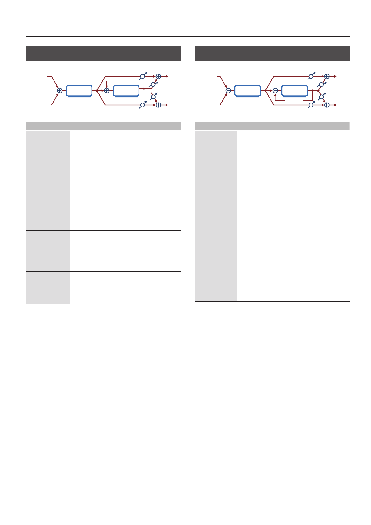
MFX/IFX Parameters
OD
0
Flanger (Overdrive
L in
0
Feedback
FlangerOverdrive
R in
Parameter Value Explanation
OD Drive
(Overdrive Drive)
OD Pan
(Overdrive Pan)
Flg PreDly
(Flanger Pre Delay)
Flg Sync
(Flanger Rate
(sync switch))
F. Delay
(Flanger Rate (Hz))
F. Rate Nt
(Flanger Rate (note))
Flg Depth
(Flanger Depth)
Flg Fbk
(Flanger Feedback)
Flg Bal
(Flanger Balance)
Level
0–127
L64–63R
0.0–100 [msec]
OFF, ON
0.05–10.00 [Hz]
Note
& “Note” (p. 64)
0–127 Depth of modulation
-98–+98 [%]
D100: 0W–D0:
100W
0–127 Output Level
Degree of distortion
Also changes the volume.
Stereo location of the overdrive
sound
Adjusts the delay time from when the
direct sound begins until the anger
sound is heard.
If this is ON, the rate synchronizes
with the tempo of the rhythm.
& “Tempo” (p. 16)
Frequency of modulation
Adjusts the proportion of the anger
sound that is fed back into the eect.
Negative (-) settings will invert the
phase.
Adjusts the volume balance between
the sound that is sent through the
anger (W) and the sound that is not
sent through the anger (D).
Flanger)
Balance D
Balance D
Balance W
Balance W
L out
R out
OD
0
Delay (Overdrive
0
Delay)
L in
DelayOverdrive
Feedback
R in
Parameter Value Explanation
OD Drive
(Overdrive Drive)
OD Pan
(Overdrive Pan)
Delay Sync
(Delay Time
(sync switch))
D. Time
(Delay Time (msec))
D. Time Nt
(Delay Time (note))
Delay Fbk
(Delay Feedback)
Dly HF
(Delay HF Damp)
Dly Bal
(Delay Balance)
Level
0–127
L64–63R Stereo location of the overdrive sound
OFF, ON
1–2600
Note
& “Note” (p. 64)
-98–+98 [%]
200, 250, 315, 400,
500, 630, 800,
1000, 1250, 1600,
2000, 2500, 3150,
4000, 5000, 6300,
8000, BYPASS [Hz]
D100: 0W–D0:
100W
0–127 Output Level
Degree of distortion
Also changes the volume.
If this is ON, the rate synchronizes with
the tempo of the rhythm.
& “Tempo” (p. 16)
Adjusts the delay time from the direct
sound until the delay sound is heard.
Adjusts the proportion of the delay
sound that is fed back into the eect.
Negative (-) settings will invert the
phase.
Adjusts the frequency above which
sound fed back to the eect will be
cut. If you do not want to cut the high
frequencies, set this parameter to
BYPASS.
Adjusts the volume balance between
the sound that is sent through the
delay (W) and the sound that is not
sent through the delay (D).
Balance D
L out
Balance W
Balance W
R out
Balance D
43
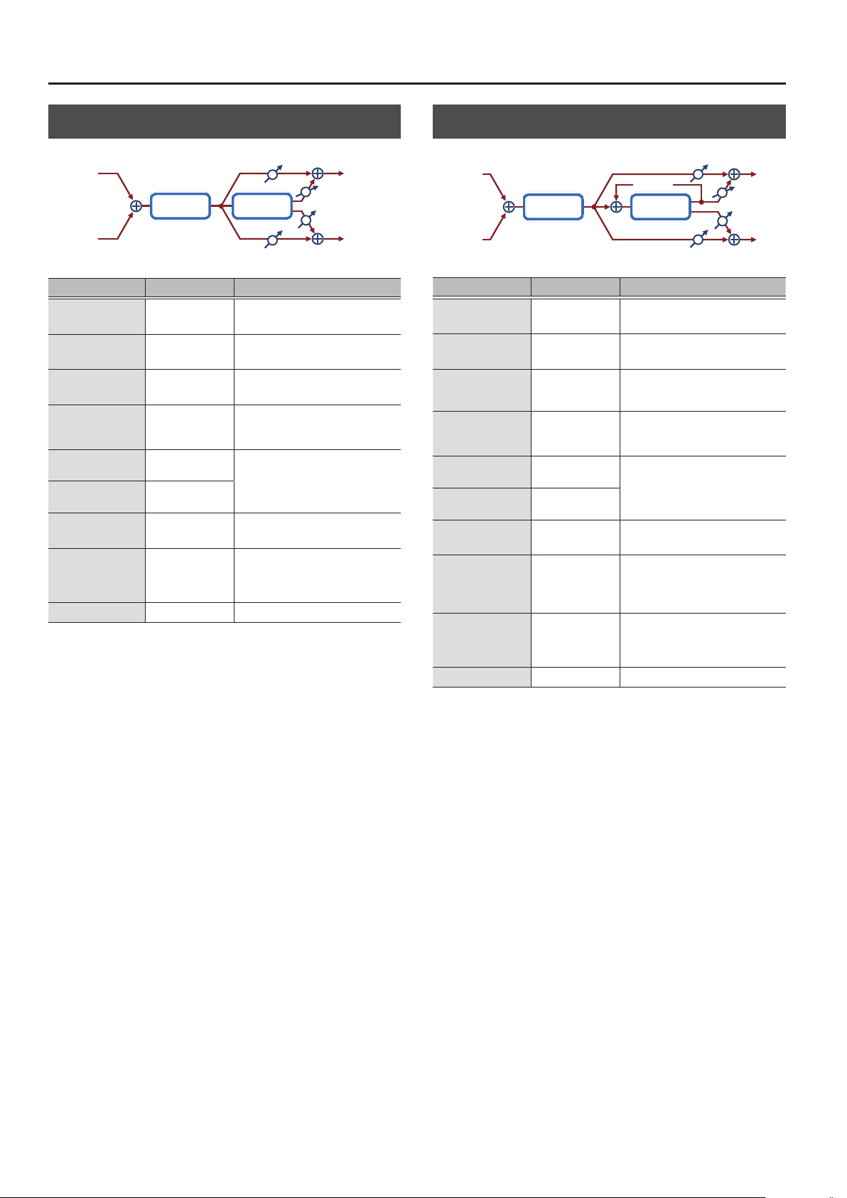
MFX/IFX Parameters
DS
0
Chorus (Distortion
0
Balance D
L in
Distortion Chorus
R in
Balance D
Parameter Value Explanation
Dist Drive
(Distortion Drive)
Dist Pan
(Distortion Pan)
Cho PreDly
(Chorus Pre Delay)
Cho Sync
(Chorus Rate
(sync switch))
C. Rate
(Chorus Rate (Hz))
C. Rate Nt
(Chorus Rate (note))
Cho Depth
(Chorus Depth)
Cho Bal
(Chorus Balance)
Level
0–127
L64–63R Stereo location of the overdrive sound
0.0–100 [msec]
OFF, ON
0.05–10.00 [Hz]
Note
& “Note” (p. 64)
0–127 Depth of modulation
D100: 0W–D0:
100W
0–127 Output Level
Degree of distortion
Also changes the volume.
Adjusts the delay time from the direct
sound until the chorus sound is heard.
If this is ON, the rate synchronizes with
the tempo of the rhythm.
& “Tempo” (p. 16)
Frequency of modulation
Adjusts the volume balance between
the sound that is sent through the
chorus (W) and the sound that is not
sent through the chorus (D).
Chorus)
L out
Balance W
Balance W
R out
DS
0
Flanger (Distortion
L in
0
Feedback
FlangerDistortion
R in
Parameter Value Explanation
Dist Drive
(Distortion Drive)
Dist Pan
(Distortion Pan)
Flg PreDly
(Flanger Pre Delay)
Flg Sync
(Flanger Rate
(sync switch))
F. Delay
(Flanger Rate (Hz))
F. Rate Nt
(Flanger Rate (note))
Flg Depth
(Flanger Depth)
Flg Fbk
(Flanger Feedback)
Flg Bal
(Flanger Balance)
Level
0–127
L64–63R
0.0–100 [msec]
OFF, ON
0.05–10.00 [Hz]
Note
& “Note” (p. 64)
0–127 Depth of modulation
-98–+98 [%]
D100: 0W–D0:
100W
0–127 Output Level
Degree of distortion
Also changes the volume.
Stereo location of the overdrive
sound
Adjusts the delay time from when the
direct sound begins until the anger
sound is heard.
If this is ON, the rate synchronizes
with the tempo of the rhythm.
& “Tempo” (p. 16)
Frequency of modulation
Adjusts the proportion of the anger
sound that is fed back into the eect.
Negative (-) settings will invert the
phase.
Adjusts the volume balance between
the sound that is sent through the
anger (W) and the sound that is not
sent through the anger (D).
Flanger)
Balance D
L out
Balance W
Balance W
R out
Balance D
44

MFX/IFX Parameters
DS
0
Delay (Distortion
0
Delay)
L in
DelayDistortion
Feedback
R in
Parameter Value Explanation
Dist Drive
(Distortion Drive)
Dist Pan
(Distortion Pan)
Delay Sync
(Delay Time
(sync switch))
D. Time
(Delay Time (msec))
D. Time Nt
(Delay Time (note))
Delay Fbk
(Delay Feedback)
Dly HF
(Delay HF Damp)
Dly Bal
(Delay Balance)
Level
0–127
L64–63R
OFF, ON
1–2600
Note
& “Note” (p. 64)
-98–+98 [%]
200, 250, 315, 400,
500, 630, 800,
1000, 1250, 1600,
2000, 2500, 3150,
4000, 5000, 6300,
8000, BYPASS [Hz]
D100: 0W–D0:
100W
0–127 Output Level
Degree of distortion
Also changes the volume.
Stereo location of the overdrive
sound
If this is ON, the rate synchronizes
with the tempo of the rhythm.
& “Tempo” (p. 16)
Adjusts the delay time from the
direct sound until the delay sound
is heard.
Adjusts the proportion of the delay
sound that is fed back into the eect.
Negative (-) settings will invert the
phase.
Adjusts the frequency above which
sound fed back to the eect will be
cut. If you do not want to cut the
high frequencies, set this parameter
to BYPASS.
Adjusts the volume balance between
the sound that is sent through the
delay (W) and the sound that is not
sent through the delay (D).
Balance D
Balance D
Balance W
Balance W
L out
R out
OD/DS
0
0
T. Wah (Overdrive/Distortion
Touch Wah)
L in
Overdrive/
Distortion
Amp
Simulator
Touch
Wah
2-Band
R in
Parameter Value Explanation
Drive Switch
D. Type
(Drive Type)
Drive
Tone
Amp Switch
AmpType
(Amp Type)
TWah Switch
(TouchWah Switch)
TWah Mode
(TouchWah Mode)
TWah Polar
(TouchWah Polarity)
TWah Sens
(TouchWah Sens)
TWah Manual
(TouchWah Manual)
TWah Peak
(TouchWah Peak)
TWah Bal
(TouchWah Balance)
Low Gain
High Gain
Level
OFF, ON Turns overdrive/distortion on/o
OVERDRIVE,
DISTORTION
0–127
0–127 Sound quality of the Overdrive eect
OFF, ON Turns the Amp Simulator on/o.
SMALL, BUILT-IN,
2-STACK, 3-STACK
OFF, ON Wah on/o
LPF, BPF
DOWN, UP
0–127
0–127
0–127
D100: 0W–D0:
100W
-15–+15 [dB]
-15–+15 [dB]
0–127 Output Level
Type of distortion
Degree of distortion. Also changes
the volume.
Type of guitar amp
SMALL: Small amp
BUILT-IN: Single-unit type amp
2-STACK: Large double stack amp
3-STACK: Large triple stack amp
Type of lter
LPF: The wah eect will be applied
over a wide frequency range.
BPF: The wah eect will be applied
over a narrow frequency range.
Direction in which the lter will move
UP: The lter will change toward a
higher frequency.
DOWN: The lter will change toward
a lower frequency.
Sensitivity with which the lter is
modied
Center frequency at which the wah
eect is applied
Width of the frequency region at
which the wah eect is applied
Increasing this value will make the
frequency region narrower.
Adjusts the volume balance between
the sound that is sent through the
wah (W) and the sound that is not
sent through the wah (D).
Amount of boost/cut for the lowfrequency range
Amount of boost/cut for the highfrequency range
EQ
L out
Pan L
Pan R
R out
45

MFX/IFX Parameters
OD/DS
0
0
A. Wah (Overdrive/Distortion
Auto Wah)
L in
Overdrive/
Distortion
Amp
Simulator
Auto Wah
2-Band
R in
Parameter Value Explanation
Drive Switch
D. Type
(Drive Type)
Drive
Tone
Amp Switch
AmpType
(Amp Type)
AWah Switch
(AutoWah Switch)
AWah Mode
(AutoWah Mode)
AWah Manual
(AutoWah Manual)
AWah Peak
(AutoWah Peak)
AWah Sync
(AutoWah Rate
(sync switch))
AWRate
(AutoWah Rate (Hz))
AWRate Nt
(AutoWah Rate (note))
AWah Depth
(AutoWah Depth)
AWah Bal
(AutoWah Balance)
Low Gain
High Gain
Level
OFF, ON Turns overdrive/distortion on/o
OVERDRIVE,
DISTORTION
0–127
0–127
OFF, ON Turns the Amp Simulator on/o.
SMALL, BUILT-IN,
2-STACK, 3-STACK
OFF, ON Wah on/o
LPF, BPF
0–127
0–127
OFF, ON
0.05–10.00 [Hz]
Note
& “Note” (p. 64)
0–127
D100: 0W–D0:
100W
-15–+15 [dB]
-15–+15 [dB]
0–127 Output Level
Type of distortion
Degree of distortion. Also changes
the volume.
Sound quality of the Overdrive
eect
Type of guitar amp
SMALL: Small amp
BUILT-IN: Single-unit type amp
2-STACK: Large double stack amp
3-STACK: Large triple stack amp
Type of lter
LPF: The wah eect will be applied
over a wide frequency range.
BPF: The wah eect will be applied
over a narrow frequency range.
Center frequency at which the wah
eect is applied
Width of the frequency region at
which the wah eect is applied
Increasing this value will make the
frequency region narrower.
If this is ON, the rate synchronizes
with the tempo of the rhythm.
& “Tempo” (p. 16)
Frequency of modulation
Depth at which the wah eect is
modulated
Adjusts the volume balance
between the sound that is sent
through the wah (W) and the
sound that is not sent through the
wah (D).
Amount of boost/cut for the lowfrequency range
Amount of boost/cut for the highfrequency range
EQ
L out
Pan L
Pan R
R out
46

MFX/IFX Parameters
0
Gt
Chorus (Guitar Amp Simulator
Chorus)
SpeakerPre Amp Chorus
R in
Parameter Value Explanation
Pre Amp Sw
(Pre Amp Switch)
Type
(Pre Amp Type)
Drive
(Pre Amp Drive)
Master Lv
(Pre Amp Master)
Gain
(Pre Amp Gain)
Bass
(Pre Amp Bass)
Middle
(Pre Amp Middle)
Treble
(Pre Amp Treble)
Speaker Sw
(Speaker Switch)
OFF, ON Turns the amp switch on/o.
Type of guitar amp
JC-120
CLEAN TWIN This models a Fender Twin Reverb.
MATCH DRIVE
BG LEAD
MS1959I
MS1959II
MS1959I+II
SLDN LEAD
METAL 5150
METAL LEAD
OD-1
OD-2 TURBO
DISTORTION
FUZZ A fuzz sound with rich harmonic content.
0–127
0–127 Volume of the entire pre-amp
LOW, MIDDLE,
HIGH
0–127
0–127
0–127
OFF, ON
This models the sound of the Roland
JC-120.
This models the sound input to left input
on a Matchless D/C-30.
A simulation of the latest tube amp
widely used in styles from blues and rock.
This models the lead sound of the MESA/
Boogie combo amp.
The sound of a tube amp typical of the
late ‘70s to ‘80s.
This models the sound input to Input I on
a Marshall 1959.
This is a trebly sound suited to hard rock.
This models the sound input to Input II on
a Marshall 1959.
The sound of connecting inputs I and II
of the guitar amp in parallel, creating a
sound with a stronger low end than I.
This models a Soldano SLO-100. This is
the typical sound of the eighties.
This models the lead channel of a Peavey
EVH 5150.
This is distortion sound that is ideal for
performances of heavy ris.
This models the sound of the BOSS OD-1.
This produces sweet, mild distortion.
This is the high-gain overdrive sound of
the BOSS OD-2.
This gives a basic, traditional distortion
sound.
Volume and amount of distortion of the
amp
Amount of pre-amp distortion
Tone of the bass/mid/treble frequency
range
Middle cannot be set if “MATCH DRIVE”
is selected as the Pre Amp Type.
Selects whether the sound will be sent
through the speaker simulation (ON) or
not (OFF)
Balance D
Balance D
0
Balance
Balance W
L outL in
W
R out
Parameter Value Explanation
Cabinet
small
open-back
enclosure
small
open-back
enclosure
open back
enclosure
open back
enclosure
open back
enclosure
open back
enclosure
open back
enclosure
open back
enclosure
open back
enclosure
sealed
enclosure
large sealed
enclosure
large sealed
enclosure
large sealed
enclosure
large double
stack
large double
stack
large triple
stack
Adjusts the delay time from the direct
sound until the chorus sound is heard.
Adjusts the volume balance between the
sound that is sent through the chorus (W)
and the sound that is not sent through
the chorus (D).
SpType
(Speaker Type)
Chorus Sw
(Chorus Switch)
Cho PreDly
(Chorus Pre Delay)
C. Rate
(Chorus Rate (Hz))
Cho Depth
(Chorus Depth)
Cho Bal
(Chorus Balance)
Level
SMALL 1
SMALL 2
MIDDLE
JC-120
BUILT-IN1
BUILT-IN2
BUILT-IN3
BUILT-IN4
BUILT-IN5
BG STACK1
BG STACK2
MS STACK1
MS STACK2
METAL STACK
2-STACK
3-STACK
OFF, ON Chorus on/o
0.0–100 [msec]
0.05–10.00 [Hz] Frequency of modulation
0–127 Depth of modulation
D100: 0W–D0:
100W
0–127 Output Level
Diameter
(in inches)
and number
of the
speaker
12 x 1 dynamic
12 x 2 dynamic
12 x 2 dynamic
12 x 2 condenser
12 x 2 condenser
12 x 2 condenser
12 x 2 condenser
12 x 2 condenser
12 x 2 condenser
12 x 4 condenser
12 x 4 condenser
12 x 4 condenser
12 x 4 condenser
12 x 4 condenser
Microphone
10 dynamic
10 dynamic
47

MFX/IFX Parameters
0
GT
0
Flanger (Guitar Amp Simulator
Flanger)
L in
R in
Parameter Value Explanation
Pre Amp Sw
(Pre Amp Switch)
OFF, ON Turns the amp switch on/o.
Type of guitar amp
This models the sound of the Roland
JC-120.
This models the sound input to left input
on a Matchless D/C-30.
A simulation of the latest tube amp
widely used in styles from blues and rock.
This models the lead sound of the MESA/
Boogie combo amp.
The sound of a tube amp typical of the
late ‘70s to ‘80s.
This models the sound input to Input I on
a Marshall 1959.
This is a trebly sound suited to hard rock.
This models the sound input to Input II on
a Marshall 1959.
The sound of connecting inputs I and II
of the guitar amp in parallel, creating a
sound with a stronger low end than I.
This models a Soldano SLO-100. This is
the typical sound of the eighties.
This models the lead channel of a Peavey
EVH 5150.
This is distortion sound that is ideal for
performances of heavy ris.
This models the sound of the BOSS OD-1.
This produces sweet, mild distortion.
This is the high-gain overdrive sound of
the BOSS OD-2.
This gives a basic, traditional distortion
sound.
Volume and amount of distortion of the
amp
Amount of pre-amp distortion
Tone of the bass/mid/treble frequency
range
Middle cannot be set if “MATCH DRIVE”
is selected as the Pre Amp Type.
Selects whether the sound will be sent
through the speaker simulation (ON) or
not (OFF)
Type
(Pre Amp Type)
Drive
(Pre Amp Drive)
Master Lv
(Pre Amp Master)
Gain
(Pre Amp Gain)
Bass
(Pre Amp Bass)
Middle
(Pre Amp Middle)
Treble
(Pre Amp Treble)
Speaker Sw
(Speaker Switch)
JC-120
CLEAN TWIN This models a Fender Twin Reverb.
MATCH DRIVE
BG LEAD
MS1959I
MS1959II
MS1959I+II
SLDN LEAD
METAL 5150
METAL LEAD
OD-1
OD-2 TURBO
DISTORTION
FUZZ A fuzz sound with rich harmonic content.
0–127
0–127 Volume of the entire pre-amp
LOW, MIDDLE,
HIGH
0–127
0–127
0–127
OFF, ON
Feedback
FlangerPre Amp Speaker
Balance D
Balance D
L out
Balance W
Balance W
R out
Parameter Value Explanation
Cabinet
small
open-back
enclosure
small
open-back
enclosure
open back
enclosure
open back
enclosure
open back
enclosure
open back
enclosure
open back
enclosure
open back
enclosure
open back
enclosure
sealed
enclosure
large sealed
enclosure
large sealed
enclosure
large sealed
enclosure
large double
stack
large double
stack
large triple
stack
Adjusts the delay time from when the
direct sound begins until the anger
sound is heard.
Adjusts the proportion of the anger
sound that is fed back into the eect.
Negative (-) settings will invert the phase.
Adjusts the volume balance between the
sound that is sent through the anger
(W) and the sound that is not sent
through the anger (D).
SpType
(Speaker Type)
Flg Switch
(Flanger Switch)
Flg PreDly
(Flanger Pre Delay)
F. Rate
(Flanger Rate (Hz))
Flg Depth
(Flanger Depth)
Flg Fbk
(Flanger Feedback)
Flg Bal
(Flanger Balance)
Level
SMALL 1
SMALL 2
MIDDLE
JC-120
BUILT-IN1
BUILT-IN2
BUILT-IN3
BUILT-IN4
BUILT-IN5
BG STACK1
BG STACK2
MS STACK1
MS STACK2
METAL STACK
2-STACK
3-STACK
OFF, ON Flanger on/o
0.0–100 [msec]
0.05–10.00 [Hz] Frequency of modulation
0–127 Depth of modulation
-98–+98 [%]
D100: 0W–D0:
100W
0–127 Output Level
Diameter
(in inches)
and number
of the
speaker
12 x 1 dynamic
12 x 2 dynamic
12 x 2 dynamic
12 x 2 condenser
12 x 2 condenser
12 x 2 condenser
12 x 2 condenser
12 x 2 condenser
12 x 2 condenser
12 x 4 condenser
12 x 4 condenser
12 x 4 condenser
12 x 4 condenser
12 x 4 condenser
Microphone
10 dynamic
10 dynamic
48

MFX/IFX Parameters
0
Gt
Phaser (Guitar Amp Simulator
Phaser)
L in
PhaserPre Amp Speaker
R in
Parameter Value Explanation
Pre Amp Sw
(Pre Amp Switch)
Type
(Pre Amp Type)
Drive
(Pre Amp Drive)
Master Lv
(Pre Amp Master)
Gain
(Pre Amp Gain)
Bass
(Pre Amp Bass)
Middle
(Pre Amp Middle)
Treble
(Pre Amp Treble)
Speaker Sw
(Speaker Switch)
OFF, ON Turns the amp switch on/o.
JC-120
CLEAN TWIN This models a Fender Twin Reverb.
MATCH DRIVE
BG LEAD
MS1959I
MS1959II
MS1959I+II
SLDN LEAD
METAL 5150
METAL LEAD
OD-1
OD-2 TURBO
DISTORTION
FUZZ A fuzz sound with rich harmonic content.
0–127
0–127 Volume of the entire pre-amp
LOW, MIDDLE,
HIGH
0–127
0–127
0–127
OFF, ON
Resonance
Type of guitar amp
This models the sound of the Roland
JC-120.
This models the sound input to left input
on a Matchless D/C-30.
A simulation of the latest tube amp
widely used in styles from blues and rock.
This models the lead sound of the MESA/
Boogie combo amp.
The sound of a tube amp typical of the
late ‘70s to ‘80s.
This models the sound input to Input I on
a Marshall 1959.
This is a trebly sound suited to hard rock.
This models the sound input to Input II on
a Marshall 1959.
The sound of connecting inputs I and II
of the guitar amp in parallel, creating a
sound with a stronger low end than I.
This models a Soldano SLO-100. This is
the typical sound of the eighties.
This models the lead channel of a Peavey
EVH 5150.
This is distortion sound that is ideal for
performances of heavy ris.
This models the sound of the BOSS OD-1.
This produces sweet, mild distortion.
This is the high-gain overdrive sound of
the BOSS OD-2.
This gives a basic, traditional distortion
sound.
Volume and amount of distortion of the
amp
Amount of pre-amp distortion
Tone of the bass/mid/treble frequency
range
Middle cannot be set if “MATCH DRIVE”
is selected as the Pre Amp Type.
Selects whether the sound will be sent
through the speaker simulation (ON) or
not (OFF)
Mix
0
L out
R out
Parameter Value Explanation
Cabinet
small
open-back
enclosure
small
open-back
enclosure
open back
enclosure
open back
enclosure
open back
enclosure
open back
enclosure
open back
enclosure
open back
enclosure
open back
enclosure
sealed
enclosure
large sealed
enclosure
large sealed
enclosure
large sealed
enclosure
large double
stack
large double
stack
large triple
stack
Adjusts the basic frequency from which
the sound will be modulated.
SpType
(Speaker Type)
Phaser SW
(Phaser Switch)
P. Rate
(Phaser Rate (Hz))
Phs Manual
(Phaser Manual)
Phs Depth
(Phaser Depth)
Phs Reso
(Phaser Resonance)
Phs Mix
(Phaser Mix)
Level
SMALL 1
SMALL 2
MIDDLE
JC-120
BUILT-IN1
BUILT-IN2
BUILT-IN3
BUILT-IN4
BUILT-IN5
BG STACK1
BG STACK2
MS STACK1
MS STACK2
METAL STACK
2-STACK
3-STACK
OFF, ON Phaser on/o
0.05–10.00 [Hz] Frequency of modulation
0–127
0–127 Depth of modulation
0–127 Amount of feedback
0–127 Level of the phase-shifted sound
0–127 Output Level
Diameter
(in inches)
and number
of the
speaker
12 x 1 dynamic
12 x 2 dynamic
12 x 2 dynamic
12 x 2 condenser
12 x 2 condenser
12 x 2 condenser
12 x 2 condenser
12 x 2 condenser
12 x 2 condenser
12 x 4 condenser
12 x 4 condenser
12 x 4 condenser
12 x 4 condenser
12 x 4 condenser
Microphone
10 dynamic
10 dynamic
49

MFX/IFX Parameters
0
Gt
Delay (Guitar Amp Simulator
Delay)
L in
R in
Parameter Value Explanation
Pre Amp Sw
(Pre Amp Switch)
Type
(Pre Amp Type)
Drive
(Pre Amp Drive)
Master Lv
(Pre Amp Master)
Gain
(Pre Amp Gain)
Bass
(Pre Amp Bass)
Middle
(Pre Amp Middle)
Treble
(Pre Amp Treble)
Speaker Sw
(Speaker Switch)
OFF, ON Turns the amp switch on/o.
Type of guitar amp
JC-120
CLEAN TWIN This models a Fender Twin Reverb.
MATCH DRIVE
BG LEAD
MS1959I
MS1959II
MS1959I+II
SLDN LEAD
METAL 5150
METAL LEAD
OD-1
OD-2 TURBO
DISTORTION
FUZZ A fuzz sound with rich harmonic content.
0–127
0–127 Volume of the entire pre-amp
LOW, MIDDLE,
HIGH
0–127
0–127
0–127
OFF, ON
This models the sound of the Roland
JC-120.
This models the sound input to left input
on a Matchless D/C-30.
A simulation of the latest tube amp
widely used in styles from blues and rock.
This models the lead sound of the MESA/
Boogie combo amp.
The sound of a tube amp typical of the
late ‘70s to ‘80s.
This models the sound input to Input I on
a Marshall 1959.
This is a trebly sound suited to hard rock.
This models the sound input to Input II on
a Marshall 1959.
The sound of connecting inputs I and II
of the guitar amp in parallel, creating a
sound with a stronger low end than I.
This models a Soldano SLO-100. This is
the typical sound of the eighties.
This models the lead channel of a Peavey
EVH 5150.
This is distortion sound that is ideal for
performances of heavy ris.
This models the sound of the BOSS OD-1.
This produces sweet, mild distortion.
This is the high-gain overdrive sound of
the BOSS OD-2.
This gives a basic, traditional distortion
sound.
Volume and amount of distortion of the
amp
Amount of pre-amp distortion
Tone of the bass/mid/treble frequency
range
Middle cannot be set if “MATCH DRIVE”
is selected as the Pre Amp Type.
Selects whether the sound will be sent
through the speaker simulation (ON) or
not (OFF)
DelayPre Amp Speaker
Feedback
Balance D
Balance D
0
Balance W
Balance W
L out
R out
Parameter Value Explanation
Cabinet
small
open-back
enclosure
small
open-back
enclosure
open back
enclosure
open back
enclosure
open back
enclosure
open back
enclosure
open back
enclosure
open back
enclosure
open back
enclosure
sealed
enclosure
large sealed
enclosure
large sealed
enclosure
large sealed
enclosure
large double
stack
large double
stack
large triple
stack
Adjusts the delay time from the direct
sound until the delay sound is heard.
Adjusts the proportion of the delay sound
that is fed back into the eect.
Negative (-) settings will invert the phase.
Frequency at which the high-frequency
portion of the delay sound will be cut
(BYPASS: no cut)
Adjusts the volume balance between the
sound that is sent through the delay (W)
and the sound that is not sent through
the delay (D).
SpType
(Speaker Type)
Delay Sw
(Delay Switch)
Dly Time
(Delay Time)
Delay Fbk
(Delay Feedback)
Dly HF
(Delay HF Damp)
Dly Bal
(Delay Balance)
Level
SMALL 1
SMALL 2
MIDDLE
JC-120
BUILT-IN1
BUILT-IN2
BUILT-IN3
BUILT-IN4
BUILT-IN5
BG STACK1
BG STACK2
MS STACK1
MS STACK2
MTL STACK
2-STACK
3-STACK
OFF, ON Delay on/o
1–1300
-98–+98 [%]
200, 250, 315,
400, 500, 630,
800, 1000, 1250,
1600, 2000,
2500, 3150,
4000, 5000,
6300, 8000,
BYPASS [Hz]
D100: 0W–D0:
100W
0–127 Output Level
Diameter
(in inches)
and number
of the
speaker
12 x 1 dynamic
12 x 2 dynamic
12 x 2 dynamic
12 x 2 condenser
12 x 2 condenser
12 x 2 condenser
12 x 2 condenser
12 x 2 condenser
12 x 2 condenser
12 x 4 condenser
12 x 4 condenser
12 x 4 condenser
12 x 4 condenser
12 x 4 condenser
Microphone
10 dynamic
10 dynamic
50

MFX/IFX Parameters
0
EP
Tremolo (EP Amp Simulator
Tremolo)
L in
SpeakerEP Amp Tremolo
R in
Parameter Value Explanation
Type of amp
A standard electric piano sound of
the early 70s
A standard electric piano sound of
the late 70s and early 80s
A standard electric piano sound of
the 60s
If this is ON, the rate synchronizes
with the tempo of the rhythm.
& “Tempo” (p. 16)
Rate of the tremolo eect
Adjusts the duty cycle of the LFO
waveform used to apply tremolo.
Type of speaker
If LINE is selected, the sound will
not be sent through the speaker
simulation.
Type
Bass
Treble
Tremolo Sw
(Tremolo Switch)
Tremolo Sync
(Tremolo Speed
(sync switch))
T. Speed
(Tremolo Speed (Hz))
T. Spd Nt
(Tremolo Speed (note))
Trm Depth
(Tremolo Depth)
Trm Duty
(Tremolo Duty)
Sp Type
(Speaker Type)
OD Switch
(Overdrive Switch)
OD Gain
(Overdrive Gain)
OD Drive
(Overdrive Drive)
Level
OLDCASE
NEWCASE
WURLY
-50–+50 Amount of low-frequency boost/cut
-50–+50 Amount of high-frequency boost/cut
OFF, ON Tremolo on/o
OFF, ON
0.05–10.00 [Hz]
Note
& “Note” (p. 64)
0–127 Depth of the tremolo eect
-10–+10
LINE, OLD, NEW,
WURLY, T WIN
OFF, ON Overdrive on/o
0–127 Overdrive input level
0–127 Degree of distortion
0–127 Output Level
0
L out
R out
EP
0
Chorus (EP Amp Simulator
0
Chorus)
Balance D
L outL in
Balance W
SpeakerEP Amp Chorus
R in
Balance D
Parameter Value Explanation
Type of amp
Type
Bass
Treble
Cho Switch
(Chorus Switch)
Cho PreDly
(Chorus Pre Delay)
Cho Sync
(Chorus Rate
(sync switch))
C. Rate
(Chorus Rate (Hz))
C. Rate Nt
(Chorus Rate (note))
Cho Depth
(Chorus Depth)
Cho Bal
(Chorus Balance)
Sp Type
(Speaker Type)
OD Switch
(Overdrive Switch)
OD Gain
(Overdrive Gain)
OD Drive
(Overdrive Drive)
Level
OLDCASE
NEWCASE
-50–+50 Amount of low-frequency boost/cut
-50–+50 Amount of high-frequency boost/cut
OFF, ON Chorus on/o
0.0–100 [msec]
OFF, ON
0.05–10.00 [Hz]
Note
& “Note” (p. 64)
0–127 Depth of modulation
D100: 0W–D0:
100W
LINE, OLD, NEW,
WURLY, T WIN
OFF, ON Overdrive on/o
0–127 Overdrive input level
0–127 Degree of distortion
0–127 Output Level
A standard electric piano sound of the
early 70s
A standard electric piano sound of the
late 70s and early 80s
Adjusts the delay time from the direct
sound until the chorus sound is heard.
If this is ON, the rate synchronizes with
the tempo of the rhythm.
& “Tempo” (p. 16)
Frequency of modulation
Adjusts the volume balance between
the sound that is sent through the
chorus (W) and the sound that is not
sent through the chorus (D).
Type of speaker
If LINE is selected, the sound will
not be sent through the speaker
simulation.
Balance W
R out
51
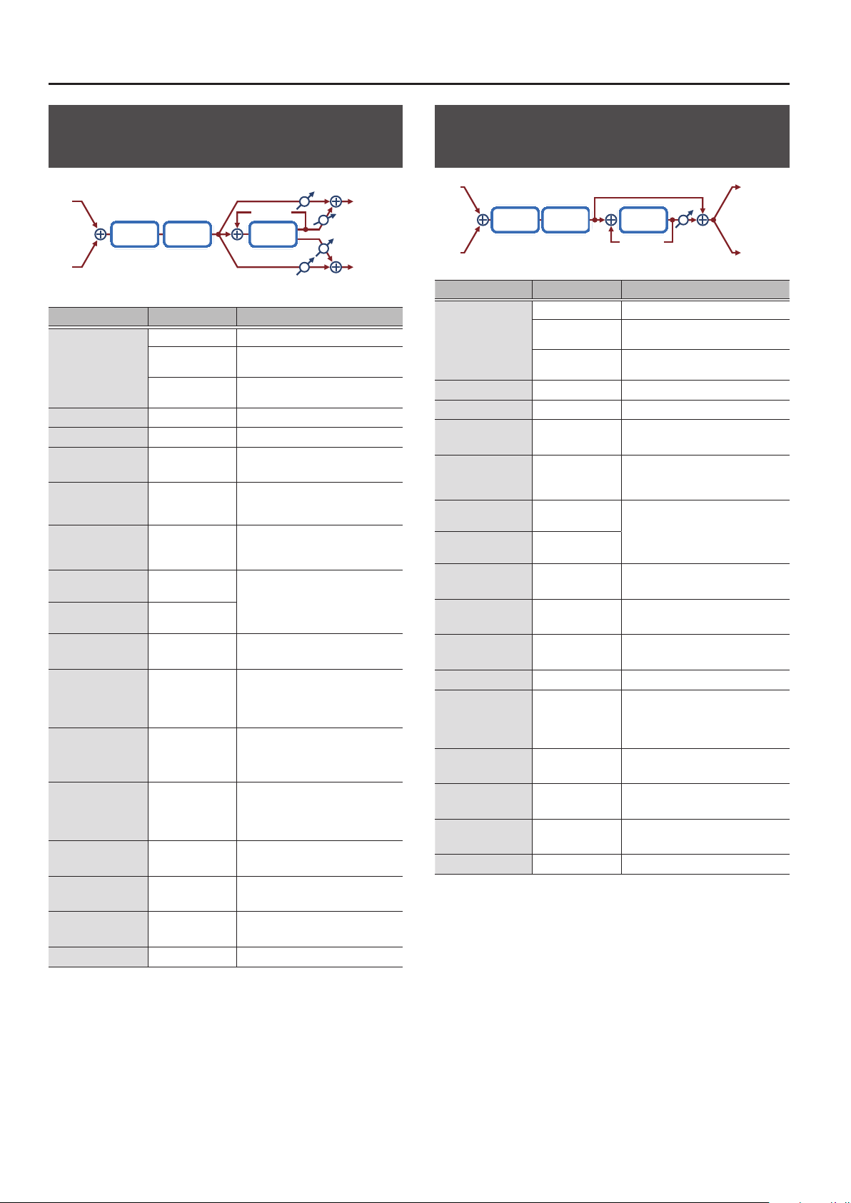
MFX/IFX Parameters
0
EP
Flanger (EP Amp Simulator
Flanger)
Balance D
L in
R in
Parameter Value Explanation
Type
Bass
Treble
Flg Switch
(Flanger Switch)
Flg PreDly
(Flanger Pre Delay)
Flg Sync
(Flanger Rate
(sync switch))
F. Rate
(Flanger Rate (Hz))
F. Rate Nt
(Flanger Rate (note))
Flg Depth
(Flanger Depth)
Flg Fbk
(Flanger Feedback)
Flg Bal
(Flanger Balance)
Sp Type
(Speaker Type)
OD Switch
(Overdrive Switch)
OD Gain
(Overdrive Gain)
OD Drive
(Overdrive Drive)
Level
OLDCASE
NEWCASE
-50–+50 Amount of low-frequency boost/cut
-50–+50 Amount of high-frequency boost/cut
OFF, ON Flanger on/o
0.0–100 [msec]
OFF, ON
0.05–10.00 [Hz]
Note
& “Note” (p. 64)
0–127 Depth of modulation
-98–+98 [%]
D100: 0W–D0:
100W
LINE, OLD, NEW,
WURLY, T WIN
OFF, ON Overdrive on/o
0–127 Overdrive input level
0–127 Degree of distortion
0–127 Output Level
Feedback
FlangerEP Amp Speaker
Balance D
Type of amp
A standard electric piano sound of
the early 70s
A standard electric piano sound of
the late 70s and early 80s
Adjusts the delay time from when the
direct sound begins until the anger
sound is heard.
If this is ON, the rate synchronizes
with the tempo of the rhythm.
& “Tempo” (p. 16)
Frequency of modulation
Adjusts the proportion of the anger
sound that is fed back into the eect.
Negative (-) settings will invert the
phase.
Adjusts the volume balance between
the sound that is sent through the
anger (W) and the sound that is not
sent through the anger (D).
Type of speaker
If LINE is selected, the sound will
not be sent through the speaker
simulation.
0
Balance W
Balance W
L out
R out
0
EP
Phaser (EP Amp Simulator
Phaser)
L in
PhaserEP Amp Speaker
R in
Parameter Value Explanation
Type
Bass
Treble
Phs Switch
(Phaser Switch)
Phs Sync
(Phaser Rate
(sync switch))
P. Rate
(Phaser Rate (Hz))
P. Rate Nt
(Phaser Rate (note))
Phs Manual
(Phaser Manual)
Phs Depth
(Phaser Depth)
Phs Reso
(Phaser Resonance)
Phs Mix (Phaser Mix)
Sp Type
(Speaker Type)
OD Switch
(Overdrive Switch)
OD Gain
(Overdrive Gain)
OD Drive
(Overdrive Drive)
Level
OLDCASE
NEWCASE
-50–+50 Amount of low-frequency boost/cut
-50–+50 Amount of high-frequency boost/cut
OFF, ON Phaser on/o
OFF, ON
0.05–10.00 [Hz]
Note
& “Note” (p. 64)
0–127
0–127 Depth of modulation
0–127 Amount of feedback
0–127 Level of the phase-shifted sound
LINE, OLD, NEW,
WURLY, T WIN
OFF, ON Overdrive on/o
0–127 Overdrive input level
0–127 Degree of distortion
0–127 Output Level
Resonance
Type of amp
A standard electric piano sound of the
early 70s
A standard electric piano sound of the
late 70s and early 80s
If this is ON, the rate synchronizes with
the tempo of the rhythm.
& “Tempo” (p. 16)
Frequency of modulation
Adjusts the basic frequency from
which the sound will be modulated.
Type of speaker
If LINE is selected, the sound will
not be sent through the speaker
simulation.
Mix
0
L out
R out
52

MFX/IFX Parameters
Speaker
Speaker
0
EP
Delay (EP Amp Simulator
Delay)
Balance D
L in
EP Amp
R in
Parameter Value Explanation
Type
Bass
Treble
Dly Switch
(Delay Switch)
Delay Sync
(Delay Time
(sync switch))
D. Time
(Delay Time (msec))
D. Time Nt
(Delay Time (note))
Dly Accel
(Delay Accel)
Delay Fbk
(Delay Feedback)
Dly HF
(Delay HF Damp)
Dly Bal
(Delay Balance)
Sp Type
(Speaker Type)
OD Switch
(Overdrive Switch)
OD Gain
(Overdrive Gain)
OD Drive
(Overdrive Drive)
Level
OLDCASE
NEWCASE
-50–+50 Amount of low-frequency boost/cut
-50–+50 Amount of high-frequency boost/cut
OFF, ON Delay on/o
OFF, ON
1–1300
Note
& “Note” (p. 64)
0–15
-98–+98 [%]
200, 250, 315, 400,
500, 630, 800,
1000, 1250, 1600,
2000, 2500, 3150,
4000, 5000, 6300,
8000, BYPASS [Hz]
D100: 0W–D0:
100W
LINE, OLD, NEW,
WURLY, T WIN
OFF, ON Overdrive on/o
0–127 Overdrive input level
0–127 Degree of distortion
0–127 Output Level
Time Ctrl
Delay
Feedback
Balance D
Type of amp
A standard electric piano sound of the
early 70s
A standard electric piano sound of the
late 70s and early 80s
If this is ON, the rate synchronizes with
the tempo of the rhythm.
& “Tempo” (p. 16)
Adjusts the delay time from the direct
sound until the delay sound is heard.
Speed at which the current delay time
changes to the specied delay time
when you change the delay time.
The speed of the pitch change will
change simultaneously with the delay
time.
Adjusts the proportion of the delay
sound that is fed back into the eect.
Negative (-) settings will invert the
phase.
Frequency at which the highfrequency portion of the delay sound
will be cut (BYPASS: no cut)
Adjusts the volume balance between
the sound that is sent through the
delay (W) and the sound that is not
sent through the delay (D).
Type of speaker
If LINE is selected, the sound will
not be sent through the speaker
simulation.
0
Balance W
Balance W
L out
R out
Enhncr
L in
R in
0
Cho (Enhancer
Enhancer
Mix
Enhancer
0
Balance D
Chorus
Balance D Mix
Parameter Value Explanation
Enh Sens
(Enhancer Sens)
Enh Mix
(Enhancer Mix)
Cho PreDly
(Chorus Pre Delay)
Cho Sync
(Chorus Rate
(sync switch))
C. Rate
(Chorus Rate (Hz))
C. Rate Nt
(Chorus Rate (note))
Cho Depth
(Chorus Depth)
Cho Bal
(Chorus Balance)
Level
0–127 Sensitivity of the enhancer
0–127
0.0–100 [msec]
OFF, ON
0.05–10.00 [Hz]
Note
& “Note” (p. 64)
0–127 Depth of modulation
D100: 0W–D0:
100W
0–127 Output Level
Level of the overtones generated by
the enhancer
Adjusts the delay time from the direct
sound until the chorus sound is heard.
If this is ON, the rate synchronizes with
the tempo of the rhythm.
& “Tempo” (p. 16)
Frequency of modulation
Adjusts the volume balance between
the sound that is sent through the
chorus (W) and the sound that is not
sent through the chorus (D).
Chorus)
L out
Balance W
Balance W
R out
53

MFX/IFX Parameters
Enhncr
L in
R in
0
Fl (Enhancer
Enhancer
Mix
Enhancer
Mix
0
Flanger)
Balance D
Feedback
Flanger
Balance D
Parameter Value Explanation
Enh Sens
(Enhancer Sens)
Enh Mix
(Enhancer Mix)
Flg PreDly
(Flanger Pre Delay)
Flg Sync
(Flanger Rate
(sync switch))
F. Rate
(Flanger Rate (Hz))
F. Rate Nt
(Flanger Rate (note))
Flg Depth
(Flanger Depth)
Flg Fbk
(Flanger Feedback)
Flg Bal
(Flanger Balance)
Level
0–127 Sensitivity of the enhancer
0–127
0.0–100 [msec]
OFF, ON
0.05–10.00 [Hz]
Note
& “Note” (p. 64)
0–127 Depth of modulation
-98–+98 [%]
D100: 0W–D0:
100W
0–127 Output Level
Level of the overtones generated by
the enhancer
Adjusts the delay time from when the
direct sound begins until the anger
sound is heard.
If this is ON, the rate synchronizes
with the tempo of the rhythm.
& “Tempo” (p. 16)
Frequency of modulation
Adjusts the proportion of the anger
sound that is fed back into the eect.
Negative (-) settings will invert the
phase.
Adjusts the volume balance between
the sound that is sent through the
anger (W) and the sound that is not
sent through the anger (D).
L out
Balance W
Balance W W
R out
L in
R in
0
Dly (Enhancer0 Delay)
Enhancer
Mix
Enhancer
Mix
Balance D
Delay
Feedback
Balance D
Enhncr
Parameter Value Explanation
Enh Sens
(Enhancer Sens)
Enh Mix
(Enhancer Mix)
Dly Sync
(Delay Time
(sync switch))
D. Time
(Delay Time (msec))
D. Time Nt
(Delay Time (note))
Delay Fbk
(Delay Feedback)
Dly HF
(Delay HF Damp)
Dly Bal
(Delay Balance)
Level
0–127 Sensitivity of the enhancer
0–127
OFF, ON
1–2600
Note
& “Note” (p. 64)
-98–+98 [%]
200, 250, 315, 400,
500, 630, 800,
1000, 1250, 1600,
2000, 2500, 3150,
4000, 5000, 6300,
8000, BYPASS [Hz]
D100: 0W–D0:
100W
0–127 Output Level
Level of the overtones generated by
the enhancer
If this is ON, the rate synchronizes with
the tempo of the rhythm.
& “Tempo” (p. 16)
Adjusts the delay time from the direct
sound until the delay sound is heard.
Adjusts the proportion of the delay
sound that is fed back into the eect.
Negative (-) settings will invert the
phase.
Adjusts the frequency above which
sound fed back to the eect will be
cut. If you do not want to cut the high
frequencies, set this parameter to
BYPASS.
Adjusts the volume balance between
the sound that is sent through the
delay (W) and the sound that is not
sent through the delay (D).
L out
Balance W
Balance W
R out
54

MFX/IFX Parameters
Chorus
0
Dly (Chorus
Balance D
0
Delay)
Balance D
L in
Balance W
Chorus
Balance W
Delay
Feedback
R in
Balance D
Balance D
Parameter Value Explanation
Cho PreDly
(Chorus Pre Delay)
Cho Sync
(Chorus Rate
(sync switch))
C. Rate
(Chorus Rate (Hz))
C. Rate Nt
(Chorus Rate (note))
Cho Depth
(Chorus Depth)
Cho Bal
(Chorus Balance)
Delay Sync
(Delay Time
(sync switch))
D. Time
(Delay Time (msec))
D. Time Nt
(Delay Time (note))
Delay Fbk
(Delay Feedback)
Dly HF
(Delay HF Damp)
Dly Bal
(Delay Balance)
Level
0.0–100 [msec]
OFF, ON
0.05–10.00 [Hz]
Note
& “Note” (p. 64)
0–127 Depth of modulation
D100: 0W–D0:
100W
OFF, ON
1–2600
Note
& “Note” (p. 64)
-98–+98 [%]
200, 250, 315, 400,
500, 630, 800,
1000, 1250, 1600,
2000, 2500, 3150,
4000, 5000, 6300,
8000, BYPASS [Hz]
D100: 0W–D0:
100W
0–127 Output Level
Adjusts the delay time from the direct
sound until the chorus sound is heard.
If this is ON, the rate synchronizes with
the tempo of the rhythm.
& “Tempo” (p. 16)
Frequency of modulation
Volume balance between the direct
sound (D) and the chorus sound (W)
If this is ON, the rate synchronizes with
the tempo of the rhythm.
& “Tempo” (p. 16)
Adjusts the delay time from the direct
sound until the delay sound is heard.
Adjusts the proportion of the delay
sound that is fed back into the eect.
Negative (-) settings will invert the
phase.
Adjusts the frequency above which
sound fed back to the eect will be
cut. If you do not want to cut the high
frequencies, set this parameter to
BYPASS.
Adjusts the volume balance between
the sound that is sent through the
delay (W) and the sound that is not
sent through the delay (D).
Balance W
Balance W
L out
R out
Flanger
0
Dly (Flanger
Balance D
0
Balance D
L in
Feedback
Flanger
Balance W
Balance W
Delay
Feedback
R in
Balance D
Balance D
Parameter Value Explanation
Flg PreDly
(Flanger Pre Delay)
Flg Sync
(Flanger Rate
(sync switch))
F. Rate
(Flanger Rate (Hz))
F. Rate Nt
(Flanger Rate (note))
Flg Depth
(Flanger Depth)
Flg Fbk
(Flanger Feedback)
Flg Bal
(Flanger Balance)
Delay Sync
(Delay Time
(sync switch))
D. Time
(Delay Time (msec))
D. Time Nt
(Delay Time (note))
Delay Fbk
(Delay Feedback)
Dly HF
(Delay HF Damp)
Dly Bal
(Delay Balance)
Level
0.0–100 [msec]
OFF, ON
0.05–10.00 [Hz]
Note
& “Note” (p. 64)
0–127 Depth of modulation
-98–+98 [%]
D100: 0W–D0:
100W
OFF, ON
1–2600
Note
& “Note” (p. 64)
-98–+98 [%]
200, 250, 315, 400,
500, 630, 800,
1000, 1250, 1600,
2000, 2500, 3150,
4000, 5000, 6300,
8000, BYPASS [Hz]
D100: 0W–D0:
100W
0–127 Output Level
Adjusts the delay time from when the
direct sound begins until the anger
sound is heard.
If this is ON, the rate synchronizes
with the tempo of the rhythm.
& “Tempo” (p. 16)
Frequency of modulation
Adjusts the proportion of the anger
sound that is fed back into the eect.
Negative (-) settings will invert the
phase.
Volume balance between the direct
sound (D) and the anger sound (W)
If this is ON, the rate synchronizes
with the tempo of the rhythm.
& “Tempo” (p. 16)
Adjusts the delay time from the direct
sound until the delay sound is heard.
Adjusts the proportion of the delay
sound that is fed back into the eect.
Negative (-) settings will invert the
phase.
Adjusts the frequency above which
sound fed back to the eect will be
cut. If you do not want to cut the
high frequencies, set this parameter
to BYPASS.
Adjusts the volume balance between
the sound that is sent through the
delay (W) and the sound that is not
sent through the delay (D).
Delay)
L out
Balance
Balance
R out
55

MFX/IFX Parameters
SBF-325
SBF-325
Chorus
0
Fl (Chorus
Balance D
0
Flanger)
L in
Balance W
Chorus Flanger
Balance W
Feedback
R in
Balance D
Parameter Value Explanation
Cho PreDly
(Chorus Pre Delay)
Cho Sync
(Chorus Rate
(sync switch))
C. Rate
(Chorus Rate (Hz))
C. Rate Nt
(Chorus Rate (note))
Cho Depth
(Chorus Depth)
Cho Bal
(Chorus Balance)
Flg PreDly
(Flanger Pre Delay)
Flg Sync (Flanger
Rate (sync switch))
F. Rate
(Flanger Rate (Hz))
F. Rate Nt
(Flanger Rate (note))
Flg Depth
(Flanger Depth)
Flg Fbk
(Flanger Feedback)
Flg Bal
(Flanger Balance)
Level
0.0–100 [msec]
OFF, ON
0.05–10.00 [Hz]
Note
& “Note” (p. 64)
0–127
D100: 0W–D0:
100W
0.0–100 [msec]
OFF, ON
0.05–10.00 [Hz]
Note
& “Note” (p. 64)
0–127
-98–+98 [%]
D100: 0W–D0:
100W
0–127 Output Level
Adjusts the delay time from the
direct sound until the chorus sound
is heard.
If this is ON, the rate synchronizes
with the tempo of the rhythm.
& “Tempo” (p. 16)
Modulation frequency of the chorus
eect
Modulation depth of the chorus
eect
Volume balance between the direct
sound (D) and the chorus sound (W)
Adjusts the delay time from when the
direct sound begins until the anger
sound is heard.
If this is ON, the rate synchronizes
with the tempo of the rhythm.
& “Tempo” (p. 16)
Modulation frequency of the anger
eect
Modulation depth of the anger
eect
Adjusts the proportion of the anger
sound that is fed back into the eect.
Negative (-) settings will invert the
phase.
Adjusts the volume balance between
the sound that is sent through the
anger (W) and the sound that is not
sent through the anger (D).
Balance D
Balance D
L out
Balance W
Balance W
R out
CE-1 (Chorus)
This models the classic BOSS CE-1 chorus eect unit. It provides a chorus
sound with a distinctively analog warmth.
L in L out
CE-1
2-Band EQ
2-Band EQ
R outR in
Parameter Value Explanation
Intensity
Low Gain
High Gain
Level
0–127 Chorus depth
-15–+15 [dB]
-15–+15 [dB]
0–127 Output Level
Amount of boost/cut for the lowfrequency range
Amount of boost/cut for the highfrequency range
SBF-325 (Flanger)
This eect reproduces Roland’s SBF-325 analog anger. It provides three
types of anging eect (which adds a metallic resonance to the original
sound) and a chorus-type eect.
L in L out
R outR in
Parameter Value Explanation
Types of anging eect
FL1 A typical mono anger
A stereo anger that preserves the
stereo positioning of the original
sound
A cross-mix anger that produces a
more intense eect
If this is ON, th
tempo of the rhythm.
& “Tempo” (p. 16)
Modulation frequency of the anger
eect
Center frequency at which the anger
eect is applied
Amount by which the anging eect
is boosted
If Mode is CHO, this setting is ignored.
Phase of the right channel
modulation:
Normally, you will leave this at Normal
(NORM).
If you specify Inverted (INV), the
modulation (upward/downward
movement) of the right channel is
inverted.
Phase when mixing the anging
sound with the original sound
NORM: normal phase
INV: inverse phase
e rate synchronizes with the
Mode
Rate Sync
(Rate (sync switch))
Rate
(Rate (Hz))
Rate Note
(Rate (note))
Depth
Manual
Feedback
RMod Phase
(CH-R Modulation
Phase)
L Phase
(CH-L Phase)
R Phase
(CH-R Phase)
Level
FL2
FL3
CHO A chorus eect
OFF, ON
0.02–5.00 [Hz]
Note
& “Note” (p. 64)
0–127 Modulation depth of the anger eect
0–127
0–127
NORM, INV
0–127 Output Level
56

MFX/IFX Parameters
Double Tap
Delay
Double Tap
Delay
SDD-320 (Dimension D)
This models Roland’s DIMENSION D (SDD-320). It provides a clear chorus
sound.
L in L out
SDD-320
Parameter Value Explanation
Mode
Low Gain
High Gain
Level
1, 2, 3, 4, 1+4, 2+4,
3+4
-15–+15 [dB]
-15–+15 [dB]
0–127 Output Level
2-Band EQ
2-Band EQ
Switches the mode.
Amount of boost/cut for the lowfrequency range
Amount of boost/cut for the highfrequency range
R outR in
2Tap PanDly (2 Tap Pan Delay)
Balance D
L in
Delay 1
Feedback
R in
Parameter Value Explanation
Delay Sync
(Delay Time
(sync switch))
D. Time(ms)
(Delay Time (msec))
D. Time(Nt)
(Delay Time (note))
Dly Fbk
(Delay Feedback)
Dly HF
(Delay HF Damp)
Dly1 Pan
(Delay 1 Pan)
Dly2 Pan
(Delay 2 Pan)
Dly1 Lv
(Delay 1 Level)
Dly2 Lv
(Delay 2 Level)
Low Gain
High Gain
Balance
Level
OFF, ON
1–2600
Note
& “Note” (p. 64)
-98–+98 [%]
200, 250, 315, 400,
500, 630, 800,
1000, 1250, 1600,
2000, 2500, 3150,
4000, 5000, 6300,
8000, BYPASS [Hz]
L64–63R Stereo location of Delay 1
L64–63R Stereo location of Delay 2
0–127 Volume of delay 1
0–127 Volume of delay 2
-15–+15 [dB]
-15–+15 [dB]
D100: 0W–D0:
100W
0–127 Output Level
Delay 2
Balance D
If this is ON, the delay synchronizes
with the tempo.
Adjusts the time until the second
delay sound is heard.
Adjusts the proportion of the delay
sound that is fed back into the eect.
Negative (-) settings will invert the
phase.
Adjusts the frequency above which
sound fed back to the eect is ltered
out. If you don’t want to lter out any
high frequencies, set this parameter
to BYPASS.
Amount of boost/cut for the lowfrequency range
Amount of boost/cut for the highfrequency range
Adjusts the volume balance between
the sound that is sent through the
delay (W) and the sound that is not
sent through the delay (D).
L out
Balance W
Balance W
R out
57

MFX/IFX Parameters
Envelope
Controller
Envelope
Controller
Transient
This eect lets you control the way in which the sound attacks and decays.
L outL in
R in
Parameter Value Explanation
Attack
Release
Out Gain
(Output Gain)
Sens
(Sense)
Level
-50–+50
-50–+50
-24–+12 [dB] Output gain
LOW, MID, HIGH
0–127 Output Level
R out
Character of the attack.
Higher values make the attack more
aggressive; lower values make the
attack milder.
Character of the decay.
Higher values make the sound linger;
lower values make the sound cut o
quickly.
Quickness with which the attack is
detected
Mid-Side EQ (Mid-Side Equalizer)
This eect allows the left/right signals that have similar phase to be
tonally adjusted in a dierent way than the left/right signals that have
dierent phase.
L in L out
Parameter Value Explanation
M EQ Switch
M In G
(M Input Gain)
M Low F
(M Low Frequency)
M Low G
(M Low Gain)
M Mid1 F
(M Mid1 Frequency)
M Mid1 G
(M Mid1 Gain)
M Mid1 Q
M Mid2 F
(M Mid2 Frequency)
M Mid2 G
(M Mid2 Gain)
M Mid2 Q
M Mid3 F
(M Mid3 Frequency)
M Mid3 G
(M Mid3 Gain)
M Mid3 Q
M High F
(M High Frequency)
M HighG
(M High Gain)
S EQ Switch
S In G
(S Input Gain)
Mid
Side
OFF, ON
-12.00–+12.00 [dB]
20, 25, 31, 40, 50,
63, 80, 100, 125,
160, 200, 250, 315,
400 [Hz]
-12.00–+12.00 [dB]
200, 250, 315, 400,
500, 630, 800,
1000, 1250, 1600,
2000, 2500, 3150,
4000, 5000, 6300,
8000 [Hz]
-12.00–+12.00 [dB] Gain of the middle range 1
0.5, 1.0, 2.0, 4.0, 8.0
200, 250, 315, 400,
500, 630, 800,
1000, 1250, 1600,
2000, 2500, 3150,
4000, 5000, 6300,
8000 [Hz]
-12.00–+12.00 [dB] Gain of the middle range 2
0.5, 1.0, 2.0, 4.0, 8.0
200, 250, 315, 400,
500, 630, 800,
1000, 1250, 1600,
2000, 2500, 3150,
4000, 5000, 6300,
8000 [Hz]
-12.00–+12.00 [dB] Gain of the middle range 3
0.5, 1.0, 2.0, 4.0, 8.0
2000, 2500, 3150,
4000, 5000, 6300,
8000, 10000,
12500, 16000 [Hz]
-12.00–+12.00 [dB]
OFF, ON
-12.00–+12.00 [dB]
Switches whether to apply tonal
adjustment to left/right input signals
whose phase is similar (in phase).
Volume of left/right input signals
whose phase is similar (in phase)
Frequency of the low range
Amount of boost/cut for the lowfrequency range
Frequency of the middle range 1
Width of the middle range 1
Set a higher value for Q to narrow the
range to be aected.
Frequency of the middle range 2
Width of the middle range 2
Set a higher value for Q to narrow the
range to be aected.
Frequency of the middle range 3
Width of the middle range 3
Set a higher value for Q to narrow the
range to be aected.
Frequency of the high range
Amount of boost/cut for the highfrequency range
Switches whether to apply tonal
adjustment to left/right input
signals whose phase is distant
(opposite phase).
Volume of left/right signals whose
phase is distant (opposite phase)
R outR in
58

MFX/IFX Parameters
Compressor
Compressor
Compressor
Compressor
Parameter Value Explanation
S Low F
(S Low Frequency)
S Low G
(S Low Gain)
S Mid1 F
(S Mid1 Frequency)
S Mid1 G
(S Mid1 Gain)
S Mid1 Q
S Mid2 F
(S Mid2 Frequency)
S Mid2 G
(S Mid2 Gain)
S Mid2 Q
S Mid3 F
(S Mid3 Frequency)
S Mid3 G
(S Mid3 Gain)
S Mid3 Q
S High F
(S High Frequency)
S HighG
(S High Gain)
Level
20, 25, 31, 40, 50,
63, 80, 100, 125,
160, 200, 250, 315,
400 [Hz]
-12.00–+12.00 [dB]
200, 250, 315, 400,
500, 630, 800,
1000, 1250, 1600,
2000, 2500, 3150,
4000, 5000, 6300,
8000 [Hz]
-12.00–+12.00 [dB] Gain of the middle range 1
0.5, 1.0, 2.0, 4.0, 8.0
200, 250, 315, 400,
500, 630, 800,
1000, 1250, 1600,
2000, 2500, 3150,
4000, 5000, 6300,
8000 [Hz]
-12.00–+12.00 [dB] Gain of the middle range 2
0.5, 1.0, 2.0, 4.0, 8.0
200, 250, 315, 400,
500, 630, 800,
1000, 1250, 1600,
2000, 2500, 3150,
4000, 5000, 6300,
8000 [Hz]
-12.00–+12.00 [dB] Gain of the middle range 3
0.5, 1.0, 2.0, 4.0, 8.0
2000, 2500, 3150,
4000, 5000, 6300,
8000, 10000,
12500, 16000 [Hz]
-12.00–+12.00 [dB]
0–127 Output Level
Frequency of the low range
Amount of boost/cut for the lowfrequency range
Frequency of the middle range 1
Width of the middle range 1
Set a higher value for Q to narrow the
range to be aected.
Frequency of the middle range 2
Width of the middle range 2
Set a higher value for Q to narrow the
range to be aected.
Frequency of the middle range 3
Width of the middle range 3
Set a higher value for Q to narrow the
range to be aected.
Frequency of the high range
Amount of boost/cut for the highfrequency range
M/S Comp (Mid-Side Compressor)
This eect allows the left/right signals that have similar phase to be
adjusted to a dierent sense of volume than the left/right signals that
have dierent phase.
L in L out
MS
Parameter Value Explanation
M Comp Sw
(M Comp Switch)
M Attack
M Release
M Thres
(M Threshold)
M Knee
M Ratio
M Gain
(M Post Gain)
S Comp Sw (S
Compressor Switch)
S Attack
S Release
S Thres
(S Threshold)
S Knee
S Ratio
S Gain (S Post Gain)
Level
Mid
LR
/
Side
OFF, ON
0–124
0–124
-60–0 [dB]
0–30 [dB]
1: 1, 1.5: 1, 2: 1, 4: 1,
16: 1, INF: 1
0–+18 [dB] Adjusts the output gain.
OFF, ON
0–124
0–124
-60–0 [dB]
0–30 [dB]
1: 1, 1.5: 1, 2: 1, 4: 1,
16: 1, INF: 1
0–+18 [dB] Adjusts the output gain.
0–127 Output Level
Switches whether to adjust the sense
of volume for left/right input signals
whose phase is similar (in phase).
Sets the speed at which compression
starts
Adjusts the time after the signal volume
falls below the Threshold Level until
compression is no longer applied.
Adjusts the volume at which
compression begins
This is a function that smooths the onset
of compression from the uncompressed
state; it gradually applies compression
starting earlier than Threshold. Higher
values produce a smoother transition.
Compression ratio
Switches whether to adjust the sense
of volume for left/right input signals
whose phase is distant (opposite phase).
Sets the speed at which compression
starts
Adjusts the time after the signal volume
falls below the Threshold Level until
compression is no longer applied.
Adjusts the volume at which
compression begins
This is a function that smooths the onset
of compression from the uncompressed
state; it gradually applies compression
starting earlier than Threshold. Higher
values produce a smoother transition.
Compression ratio
MS
/
LR
R outR in
59

MFX/IFX Parameters
Odd
Overtone
Generator
Odd
Overtone
Generator
Even
Overtone
Generator
Even
Overtone
Generator
Odd
Overtone
Generator
Odd
Overtone
Generator
Even
Overtone
Generator
Even
Overtone
Generator
Fattener (Tone Fattener)
This eect applies distinctive distortion, adding overtones to give more
depth to the sound.
L outL in
R inR in
Parameter Value Explanation
Odd Level
Even Level
Level
0–400 [%]
0–400 [%]
0–127 Output Level
Raising the value adds odd-order
overtones.
Raising the value adds even-order
overtones.
M/S Delay (Mid Side Delay)
This eect applies dierent amounts of delay to left/right signals of similar
phase and diering phase.
L in L out
MS
Mid
LR
/
Side
Parameter Value Explanation
MD Level
MD Mode
MD Tm Sync
MD. Time
MDTime Nt
MD Feedback
MD HFDamp
MD1 Pan
MD2 Pan
MD3 Pan
MD4 Pan
SD Level
SD Mode
SD Tm Sync
SD Time
SDTime Nt
SD Feedback
SD HFDamp
SD1 Pan
SD2 Pan
SD3 Pan
SD4 Pan
Level
0–127
2TAP, 3TAP, 4TAP
OFF, ON
1–1300
Note
& “Note” (p. 64)
-98–+98 [%]
200, 250, 315, 400,
500, 630, 800,
1000, 1250, 1600,
2000, 2500, 3150,
4000, 5000, 6300,
8000, BYPASS [Hz]
L64–63R Panning of the rst delay sound
L64–63R Panning of the second delay sound
L64–63R Panning of the third delay sound
L64–63R Panning of the fourth delay sound
0–127 Output Level
Multi-Tap
Delay
Multi-Tap
Delay
Delay volume of left/right input signals
whose phase is similar (in phase)
Delay divisions for the input signals
whose left/right phase is similar
(identical phase)
If this is ON, the delay synchronizes with
the tempo.
Adjusts the delay time from the direct
sound until the delay sound is heard.
Adjusts the proportion of the delay
sound that is fed back into the eect.
Negative (-) settings will invert the
phase.
Adjusts the frequency above which
sound fed back to the eect is ltered
out. If you don’t want to lter out any
high frequencies, set this parameter to
BYPASS.
Delay volume of left/right input signals
whose phase is distant (opposite phase)
Delay divisions for the input signals
whose left/right phase is distant
(reverse phase)
If this is ON, the delay synchronizes with
the tempo.
Adjusts the delay time from the direct
sound until the delay sound is heard.
Adjusts the proportion of the delay
sound that is fed back into the eect.
Negative (-) settings will invert the
phase.
Adjusts the frequency above which
sound fed back to the eect is ltered
out. If you don’t want to lter out any
high frequencies, set this parameter to
BYPASS.
MS
/
LR
R outR in
60

MFX/IFX Parameters
Speaker
Speaker
Bass/
Treble
Bass/
Treble
Overdrive
Overdrive
Tremolo
Tremolo
Delay
Delay
Delay
Delay
EP Amp Sim (RD EP Amp Simulator)
This is an eect that was developed for the RD series SuperNatural E.Piano.
L in
R in
Parameter Value Explanation
Bass
Treble
Tremolo Sw
Type
Speed Sync
Speed
Speed Nt
Depth
Shape
AMP
Speaker
Drive
Level
-50–+50 Amount of low-frequency boost/cut
-50–+50 Amount of high-frequency boost/cut
OFF, ON Tremolo on/o
Type of tremolo eect
OLDCASE MO
OLDCASE ST
NEWCASE
DYNO A classic modied electric piano
WURLY A classic electric piano of the ‘60s
OFF, ON
0.05–10.00 [Hz]
Note
& “Note” (p. 64)
0–127 Depth of the tremolo eect
0–20 Adjusts the waveform of the tremolo.
OFF, ON Turns the speaker and distortion on/o
LINE, OLD, NEW,
WURLY, T WIN
0–127
0–127 Output Level
A standard electric piano sound of the
early 70s (mono)
A standard electric piano sound of the
early 70s (stereo)
A standard electric piano sound of the
late 70s and early 80s
If this is ON, th
tempo of the rhythm.
& “Tempo” (p. 16)
Rate of the tremolo eect
Type of speaker If LINE is selected, the
sound will not be sent through the
speaker simulation.
Degree of distortion
Also changes the volume.
e rate synchronizes with the
L out
R out
DJFX Looper
Loops a short portion of the input sound. You can vary the playback
direction and playback speed of the input sound to add turntable-type
eects.
Loop Sw
L in
Loop Sw
Speed
Control
R in
Parameter Value Explanation
Length
Speed
Loop Sw
Level
230–23
(not straight)
-1.00–+1.00
OFF, ON
0–127 Output Level
Species the length of the loop.
Species the playback direction and
playback speed.
- direction: Reverse playback
+ direction: Normal playback
0: Stop playback
As the value moves away from 0, the
playback speed becomes faster.
If you turn this on while the sound is
heard, the sound at that point will be
looped. Turn this o to cancel the loop.
* If the eect is recalled with this ON,
this parameter must be turned OFF
and then turned ON again in order to
make the loop operate.
Loop Sw
L out
Loop Sw
R out
61

MFX/IFX Parameters
Loop Sw
Control
Loop Sw
Control
Delay
Delay
Delay
Delay
Pre FilterPre Filter
OverdriveOverdrive
Post Filter1-3Post Filter1-3
Pre FilterPre Filter
OverdriveOverdrive
Post Filter1-3Post Filter1-3
BPM Looper
Loops a short portion of the input sound. This can automatically turn the
loop on/o in synchronization with the rhythm.
L in
R in
Parameter Value Explanation
Length
Rate Sync
Rate
Rate Note
Timing
Lenth
Loop Mode
Level
230–23
(not straight)
OFF, ON
0.05–10.00 [Hz]
Note
& “Note” (p. 64)
1–8
1–8
OFF, AUTO, ON
0–127 Output Level
Species the length of the loop.
If this is ON, th
tempo of the rhythm.
& “Tempo” (p. 16)
Cycle at which the loop automatically
turns on/o
Species the timing within the cycle
at which the loop automatically starts
(which step of the eight timing divisions
at which the sound is heard)
Species the length at which the loop
automatically ends within the cycle (the
number of times that the 1/8-length of
sound is heard)
If this is AUTO, the loop automatically
turns on/o in synchronization with the
rhythm.
* If the eect is recalled with this ON,
this parameter must rst be set to
something other than ON in order to
make the loop operate.
e rate synchronizes with the
L out
R out
Saturator
This eect combines overdrive and lter.
Balance D
L in L out
Balance W
Balance D
Parameter Value Explanation
Type of lter that precedes the
distortion processing
THRU: No lter is applied
LPF: A lter that passes the sound below
the specied frequency
HPF: A lter that passes the sound
above the specied frequency
LSV: A lter that boosts/cuts the sound
below the specied frequency
HSV: A lter that boosts/cuts the sound
above the specied frequency
Frequency at which the pre-distortion
lter operates
For the LSV/HSV types, the amount of
boost/cut
Type of lter 1 which follows the
distortion processing
Frequency at which post-distortion lter
1 operates
For the LSV/HSV types, the amount of
boost/cut
Type of lter 2 which follows the
distortion processing
Frequency at which post-distortion lter
2 operates
For the LSV/HSV types, the amount of
boost/cut
Type of lter 3 which follows the
distortion processing
THRU: No lter is applied
LPF: A lter that passes the sound below
the specied frequency
HPF: A lter that passes the sound
above the specied frequency
BPF: A lter that passes only the
specied frequency
PKG: A lter that boosts/cuts the
specied frequency
Frequency at which post-distortion lter
3 operates
For the PKG type, the amount of boost/
cut
Width of the frequency range aected
by the lter
Adjust this value so that the sound is
not made louder when distortion is
applied.
Volume balance between the dry sound
(D) and eect sound (W)
Pre Type
Pre Freq
Pre Gain
Drive
Post1 Type
Post1Frq
Post1Gain
Post2 Type
Post2Frq
Post2Gain
Post3 Type
Post3Frq
Post3Gain
Post3 Q
Sense
PostGain
Balance
Level
THRU, LPF, HPF,
LSV, HSV
20–16000 [Hz]
-24.0–+24.0 [dB]
0.0–48.0 [dB] Strength of distortion
THRU, LPF, HPF,
LSV, HSV
20–16000 [Hz]
-24.0–+24.0 [dB]
THRU, LPF, HPF,
LSV, HSV
20–16000 [Hz]
-24.0–+24.0 [dB]
THRU, LPF, HPF,
BPF, PKG
20–16000 [Hz]
-24.0–+24.0 [dB]
0.5–16.0
-60.0–0.0 [dB]
-48.0 +12.0 [dB] Gain following distortion processing
D100: 0W–D0:
100W
0–127 Output Level
R outR in
62

MFX/IFX Parameters
Pre Filter
Pre Filter
Low/High
Low/High
Low/High
Low/High
Overdrive
Overdrive
Post
Filter1-3
Post
Filter1-3
Pre Filter
Pre Filter
Overdrive
Overdrive
Post
Filter1-3
Post
Filter1-3
Pre Filter
Pre Filter
Pre Filter
Pre Filter
Tone
Control
Tone
Control
Tone
Control
Tone
Control
Overdrive
Overdrive
Overdrive
Overdrive
Post Filter
Post Filter
Post Filter
Post Filter
Chorus
Chorus
Noise
Generator
Noise
Generator
W Saturator (Worm Saturator)
This is a variety of saturator, and is distinctive for its warmer sound.
Balance D
L in L out
Balance W
R outR in
Balance D
Parameter Value Explanation
Input lter (low range)
Boosts/cuts the sound below the
specied frequency.
Input lter (high range)
Boosts/cuts the sound above the
specied frequency.
Type of lter that precedes the
distortion processing
THRU: No lter is applied
LPF: A lter that passes the sound below
the specied frequency
HPF: A lter that passes the sound
above the specied frequency
LSV: A lter that boosts/cuts the sound
below the specied frequency
HSV: A lter that boosts/cuts the sound
above the specied frequency
Frequency at which the pre-distortion
lter operates
For the LSV/HSV types, the amount of
boost/cut
Type of lter 1 which follows the
distortion processing
Frequency at which post-distortion lter
1 operates
For the LSV/HSV types, the amount of
boost/cut
Type of lter 2 which follows the
distortion processing
Frequency at which post-distortion lter
2 operates
For the LSV/HSV types, the amount of
boost/cut
Type of lter 3 which follows the
distortion processing
THRU: No lter is applied
LPF: A lter that passes the sound below
the specied frequency
HPF: A lter that passes the sound
above the specied frequency
BPF: A lter that passes only the
specied frequency
PKG: A lter that boosts/cuts the
specied frequency
Frequency at which post-distortion lter
3 operates
For the PKG type, the amount of boost/
cut
Width of the frequency range aected
by the lter
LowFreq
LowGain
Hi Slope
Hi Freq
Pre1 Type
Pre1Freq
Pre1Gain
Drive
Post1 Type
Post1Frq
Post1Gain
Post2 Type
Post2Frq
Post2Gain
Post3 Type
Post3Frq
Post3Gain
Post3 Q
20–16000 [Hz]
-24.0–+24.0 [dB] Amount of boost/cut
THRU, -12dB, -24dB
20–16000 [Hz] Amount of boost/cut
THRU, LPF, HPF,
LSV, HSV
20–16000 [Hz]
-24.0–+24.0 [dB]
0.0–48.0 [dB] Strength of distortion
THRU, LPF, HPF,
LSV, HSV
20–16000 [Hz]
-24.0–+24.0 [dB]
THRU, LPF, HPF,
LSV, HSV
20–16000 [Hz]
-24.0–+24.0 [dB]
THRU, LPF, HPF,
BPF, PKG
20–16000 [Hz]
-24.0–+24.0 [dB]
0.5–16.0
Parameter Value Explanation
Sense
PostGain
Balance
Level
-60.0–0.0 [dB]
-48.0–+12.0 [dB] Gain following distortion processing
D100: 0W–D0:
100W
0–127 Output Level
Adjust this value so that the sound is
not made louder when distortion is
applied.
Volume balance between the dry sound
(D) and eect sound (W)
Fuzz
Adds overtones and intensely distorts the sound.
L in L out
Parameter Value Explanation
Drive
Tone
Level
0–127
0–100 Sound quality of the Overdrive eect
0–127 Output Level
Adjusts the depth of distortion.
This also changes the volume.
JUNO Chorus (JUNO-106Chorus)
This models the chorus eects of the Roland JUNO-106.
L in
R in
Parameter Value Explanation
Type of Chorus
I+II: The state in which two buttons are
pressed simultaneously.
Volume of the noise produced by
chorus
Volume balance between the dry sound
(D) and eect sound (W)
Mode
Noise Lv
Balance
Level
I, II, I+II, JX I, JX II
0–127
D100: 0W–D0:
100W
0–127 Output Level
L out
R out
R outR in
63

MFX/IFX Parameters
Tube Model
Distortion
Tube Model
Distortion
Phaser
Phaser
Phaser
Phaser
MM Filter (Multimode Filter)
This is a lter that is adjusted for eective use in a DJ performance.
Multimode
L in
R in
Multimode
Filter
Filter
Multimode
Multimode
Filter
Filter
L out
R out
Parameter Value Explanation
Type of lter
LPF/HPF: The lter type is automatically
switched according to the Filter Tone
parameter value.
Filter resonance level
Higher values more strongly emphasize
the region of the operating frequency.
Amount of attenuation per octave
-12 dB: gentle
-24 dB: steep
-36 dB: extremely steep
Type
Tone
Color
Slope
Gain
Level
LPF/HPF, LPF, HPF,
BPF
0–255 Frequency at which the lter operates
0–255
-12, -24, -36 [dB]
0–+12 [dB] Amount of boost for the lter output
0–127 Output Level
HMS Distort
Script 100
This simulates an analog phaser of the past.
L in L out
R outR in
Parameter Value Explanation
If this is ON, th
Rate Sync
Rate
Rate Note
Duty
Min
Max
Manual Sw
Manual
Resonance
Mix
Level
OFF, ON
0.05–10.00 [Hz]
Note
& “Note” (p. 64)
-50–50
0–100 Lower limit reached by modulation
0–100 Upper limit reached by modulation
OFF, ON
0–100
0–66 Amount of feedback
0–127 Level of the phase-shifted sound
0–127 Output Level
tempo of the rhythm.
& “Tempo” (p. 16)
Frequency of modulation
Adjusts the ratio of speeds at which the
modulation rises or falls.
Applies modulation according to the
value of the Manual parameter, rather
than modulating automatically.
Adjusts the basic frequency from which
the sound will be modulated.
e rate synchronizes with the
This is a distortion-type eect that models the vacuum tube amp section
of a rotary speaker of the past.
L in
R in
L out
R out
Parameter Value Explanation
Dist
Level
0–127 Strength of distortion
0–127 Output Level
Note
1/64T
Sixty-fourth-note triplet
1/16T
Sixteenth-note triplet
1/16D 1/8 1/4T 1/8D
Dotted sixteenth note Eighth note
1/4
Quarter note
1/1T
Whole-note triplet Dotted half note Whole note Double-note triplet
1/1D 2/1
Dotted whole note Double note
1/64 1/32T 1/32
Sixty-fourth note
Dotted thirty-second note
1/2T 1/4D 1/2
Half-note triplet
1/2D 1/1 2/1T
Thirty-second-note triplet
Sixteenth note Eighth-note triplet
Quarter-note triplet Dotted eighth note
Dotted quarter note Half note
Thirty-second note
1/8T1/32D 1/16
64
 Loading...