

Eects Parameter Guide
Copyright © 2014 ROLAND CORPORATION
All rights reserved. No part of this publication may be reproduced in any form without the written permission of ROLAND CORPORATION.
01

Contents
Modulation FX Parameters. . . . . . . . . . . . . . . . . . . . . . . . . . . . . . . . 3
Controlling a Modulation FX via MIDI (Modulation FX
CONTROL) . . . . . . . . . . . . . . . . . . . . . . . . . . . . . . . . . . . . . . . . . . . . . .31
Tremolo/Amp Simulator Parameters . . . . . . . . . . . . . . . . . . . . . 32
Sympathetic Resonance Parameters . . . . . . . . . . . . . . . . . . . . . . 35
Delay Parameters . . . . . . . . . . . . . . . . . . . . . . . . . . . . . . . . . . . . . . . 36
Reverb Parameters . . . . . . . . . . . . . . . . . . . . . . . . . . . . . . . . . . . . . . 38
EQ Parameters . . . . . . . . . . . . . . . . . . . . . . . . . . . . . . . . . . . . . . . . . . 39
System Compressor Parameters . . . . . . . . . . . . . . . . . . . . . . . . . . 40
2
Modulation FX Parameters
Modulation FX eects are included in the tone.
You can choose from 56 types, most of which are eects that modulate the sound.
Parameters marked with a sharp “#” can be controlled using a “Controlling a Modulation FX via MIDI (Modulation FX CONTROL)” (p. 31).
Type Modulation FX Name Page
1 EQUALIZER p. 4
2 SPECTRUM p. 5
3 LOW BOOST p. 5
FILTER
MODULATION
CHORUS
DYNAMICS
DELAY
LO-FI
PITCH
4 STEP FILTER p. 6
5 ENHANCER p. 6
6 AUTO WAH p. 7
7 HUMANIZER p. 7
8 PHASER 1 p. 8
9 PHASER 2 p. 8
10 PHASER 3 p. 9
11 STEP PHASER p. 9
12 MULTI STAGE PHASER p. 10
13 INFINITE PHASER p. 10
14 RING MODULATOR p. 11
15 TREMOLO p. 11
16 AUTO PAN p. 12
17 SLICER p. 12
18 CHORUS p. 13
19 FLANGER p. 13
20 STEP FLANGER p. 14
21 HEXA-CHORUS p. 14
22 TREMOLO CHORUS p. 15
23 SPACE-D p. 15
24 OVERDRIVE p. 16
25 DISTORTION p. 16
26 T-SCREAM p. 16
27 COMPRESSOR p. 17
28 LIMITER p. 17
29 SUSTAINER p. 18
30 GATE p. 18
31 DELAY p. 19
32 MODULATION DELAY p. 19
33 3TAP PAN DELAY p. 20
34 4TAP PAN DELAY p. 20
35 MULTI TAP DELAY p. 21
36 REVERSE DELAY p. 21
37 TIME CTRL DELAY p. 22
38 TAPE ECHO p. 22
39 LOFI COMPRESS p. 22
40 BIT CRUSHER p. 23
41 PITCH SHIFTER p. 24
42 2VOICE PITCH SHIFTER p. 24
Type Modulation FX Name Page
COMBINATION
43
OD " CHORUS
44
OD " FLANGER
45
OD " DELAY
46
DS " CHORUS
47
DS " FLANGER
48
DS " DELAY
49
OD/DS " TWAH
50
OD/DS " AWAH
51
ENHANCER " CHORUS
52
ENHANCER " FLANGER
53
ENHANCER " DELAY
54
CHORUS " DELAY
55
FLANGER " DELAY
56
CHORUS " FLANGER
p. 25
p. 25
p. 26
p. 26
p. 26
p. 26
p. 27
p. 27
p. 28
p. 28
p. 29
p. 29
p. 30
p. 30
3

Modulation FX Parameters
Settings common to all Modulation FX
Parameter Value Explanation
Type
Routing
Refer to the eect list
(p. 3).
MOD FX
(Modulation FX)
" TR/AMP
Amp Simulator)
TR/AMP (Tremolo/Amp
Simulator)
(Modulation FX)
(Tremolo/
" MOD FX
Species the type of Modulation FX.
The editable parameters will depend
on the eect type that’s selected.
Lets you select the routing of the
Modulation FX and the Tremolo/
Amp Simulator.
By switching the Routing type, you
can change the eect that’s applied
to the sound.
For example, suppose that you
chose Chorus as the MOD FX and
chose E. PIANO for TR/AMP; with
the MOD FX " TR/AMP setting,
the chorus sound will be output in
monaural, but with the TR/AMP "
MOD FX setting it will be output in
stereo.
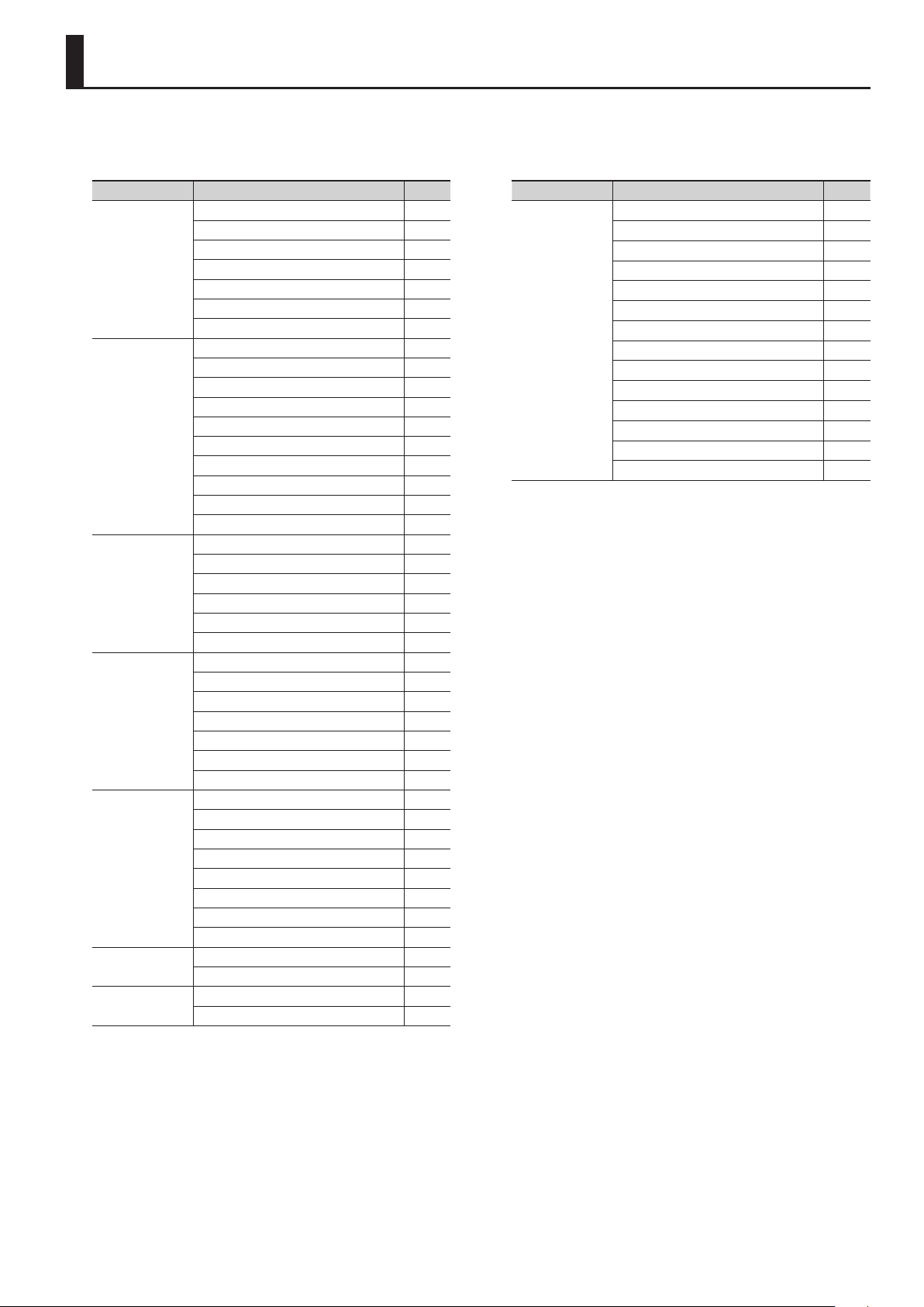
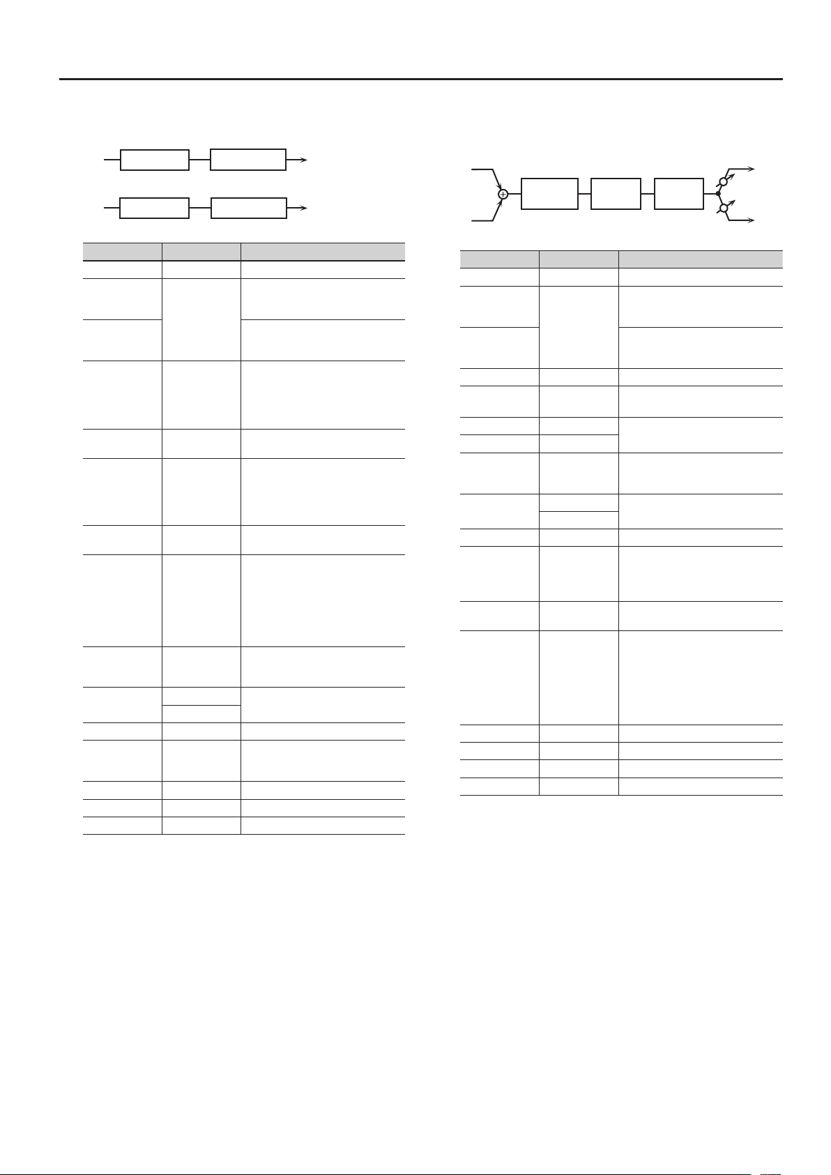
1: EQUALIZER
This is a four-band stereo equalizer (low, mid x 2, high).
L in
R in
Parameter Value Explanation
Switch OFF, ON Turns the eect on/o.
Depth Knob
Rate Knob
Low Freq 20–400 [Hz] Frequency of the low range
Low Gain # -15–+15 [dB] Gain of the low range
Mid1 Freq 200–8000 [Hz] Frequency of the middle range 1
Mid1 Gain -15–+15 [dB] Gain of the middle range 1
Mid1 Q
Mid2 Freq 200–8000 [Hz] Frequency of the middle range 2
Mid2 Gain -15–+15 [dB] Gain of the middle range 2
Mid2 Q
High Freq 2000–16000 [Hz] Frequency of the high range
High Gain # -15–+15 [dB] Gain of the high range
Level # 0–127 Output Level
4-Band EQ
4-Band EQ
LOW GAIN,
HIGH GAIN,
LEVEL
0.5, 1.0, 2.0, 4.0,
8.0
0.5, 1.0, 2.0, 4.0,
8.0
Species the parameter that is
controlled by the MODULATION FX
[DEPTH] knob.
Species the parameter that is
controlled by the MODULATION FX
[RATE] knob.
Width of the middle range 1
Set a higher value to narrow the range
to be aected.
Width of the middle range 2
Set a higher value to narrow the range
to be aected.
L out
R out
4
Modulation FX Parameters
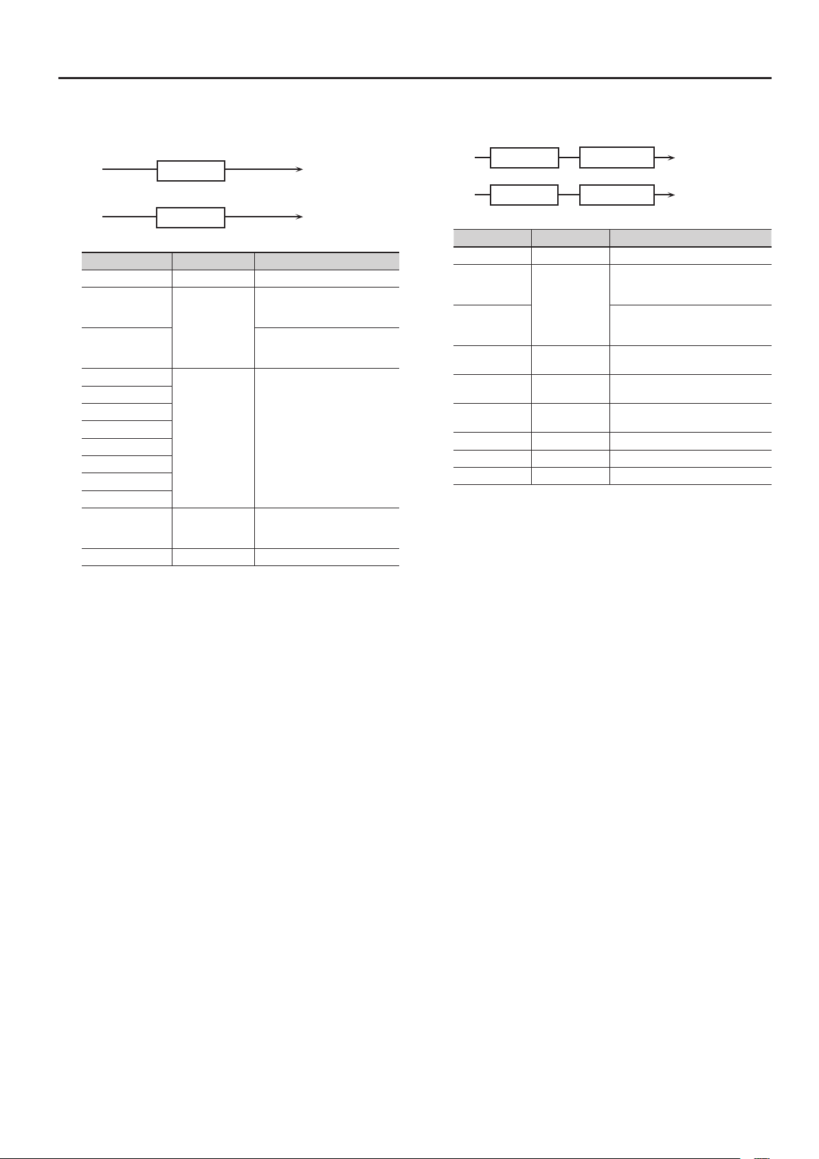
2: SPECTRUM
This is a stereo spectrum. Spectrum is a type of lter which modies
the timbre by boosting or cutting the level at specic frequencies.
L in
R in
Parameter Value Explanation
Switch OFF, ON Turns the eect on/o.
Depth Knob
Rate Knob
Band1 (250 Hz)
Band2 (500 Hz)
Band3 (1000 Hz)
Band4 (1250 Hz)
Band5 (2000 Hz)
Band6 (3150 Hz)
Band7 (4000 Hz)
Band8 (8000 Hz)
Q 0.5, 1.0, 2.0, 4.0, 8.0
Level # 0–127 Output Level
Spectrum
Spectrum
Species the parameter that is
BAND1,
BAND3,
LEVEL
-15–+15 [dB] Gain of each frequency band
controlled by the MODULATION
FX [DEPTH] knob.
Species the parameter that is
controlled by the MODULATION
FX [RATE] knob.
Simultaneously adjusts the width
of the adjusted ranges for all the
frequency bands.
L out
R out
3: LOW BOOST
Boosts the volume of the lower range, creating powerful lows.
L in
R in
Parameter Value Explanation
Switch OFF, ON Turns the eect on/o.
Depth Knob
Rate Knob
Boost Frequency
#
Boost Gain # 0–+12 [dB]
Boost Width
Low Gain -15–+15 [dB] Gain of the low frequency range
High Gain -15–+15 [dB] Gain of the high frequency range
Level 0–127 Output level
Low Boost
Low Boost
BOOST
FREQUENCY,
BOOST GAIN
50–125 [Hz]
WIDE, MID,
NARROW
2-Band EQ
2-Band EQ
Species the parameter that is
controlled by the MODULATION FX
[DEPTH] knob.
Species the parameter that is
controlled by the MODULATION FX
[RATE] knob.
Basic frequency at which the lower
range will be boosted
Amount by which the lower range will
be boosted
Width of the lower range that will be
boosted
L out
R out
5
Modulation FX Parameters
4: STEP FILTER
This is a lter whose cuto frequency can be modulated in steps. You
can specify the pattern by which the cuto frequency will change.
You can use MFX CONTROL to restart the step sequence from the
beginning (p. 31).
L in
R in
Parameter Value Explanation
Switch OFF, ON Turns the eect on/o.
Depth Knob
Rate Knob
Step 01 –16 0–127 Cuto frequency at each step
Rate (sync sw) OFF, ON
Rate (Hz) #/
Rate (note) #
Attack # 0–127
Filter Type
Filter Slope -12, -24, -36 [dB]
Filter Resonance
#
Filter Gain 0–+12 [dB] Amount of boost for the lter output
Level 0–127 Output level
Step Filter
Step Filter
RATE,
ATTACK,
FILTER
RESONANCE
0.05–10.00
note (p. 31)
LPF,
BPF,
HPF,
NOTCH
0–127
Species the parameter that is
controlled by the MODULATION FX
[DEPTH] knob.
Species the parameter that is
controlled by the MODULATION FX
[RATE] knob.
If this is ON, the modulation is
synchronized to the tempo of the
rhythm (owner’s manual p. 24).
Rate of modulation
Speed at which the cuto frequency
changes between steps
Filter type
Frequency range that will pass
through each lter
LPF: frequencies below the cuto
BPF: frequencies in the region of the
cuto
HPF: frequencies above the cuto
NOTCH: frequencies other than the
region of the cuto
Amount of attenuation per octave
-12 dB: gentle
-24 dB: steep
-36 dB: extremely steep
Filter resonance level
Increasing this value will emphasize
the region near the cuto frequency.
L out
R out
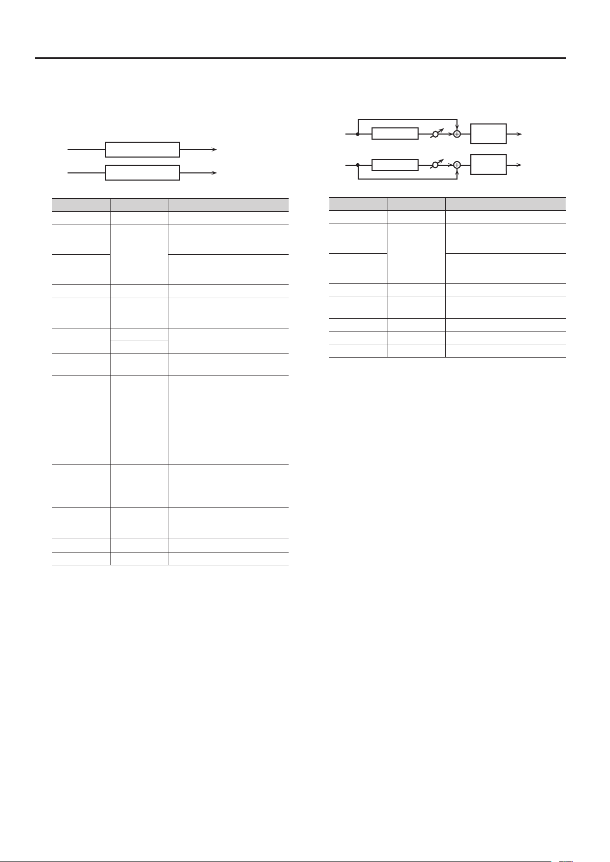
5: ENHANCER
Controls the overtone structure of the high frequencies, adding
sparkle and tightness to the sound.
L in
R in
Parameter Value Explanation
Switch OFF, ON Turns the eect on/o.
Depth Knob
Rate Knob
Sens # 0–127 Sensitivity of the enhancer
Mix # 0–127
Low Gain -15–+15 [dB] Gain of the low range
High Gain -15–+15 [dB] Gain of the high range
Level 0–127 Output Level
Enhancer
Enhancer
SENS,
MIX
Mix
Mix
2-Band
EQ
2-Band
EQ
Species the parameter that is
controlled by the MODULATION FX
[DEPTH] knob.
Species the parameter that is
controlled by the MODULATION FX
[RATE] knob.
Level of the overtones generated by
the enhancer
L out
R out
6
Modulation FX Parameters
L in
6: AUTO WAH
Cyclically controls a lter to create cyclic change in timbre.
L in
R in
Parameter Value Explanation
Switch OFF, ON Turns the eect on/o.
Depth Knob
Rate Knob
Filter Type LPF, BPF
Manual # 0–127
Peak 0–127
Sens # 0–127
Polarity UP, DOWN
Rate (sync sw) # OFF, ON
Rate (Hz) #/
Rate (note) #
Depth # 0–127 Depth of modulation
Phase # 0–180 [deg]
Low Gain -15–+15 [dB] Gain of the low range
High Gain -15–+15 [dB] Gain of the high range
Level 0–127 Output Level
Auto Wah
Auto Wah
MANUAL,
SENS,
RATE,
DEPTH,
PHASE
0.05–10.00 [Hz]
note (p. 31)
2-Band EQ
2-Band EQ
Species the parameter that is
controlled by the MODULATION FX
[DEPTH] knob.
Species the parameter that is
controlled by the MODULATION FX
[RATE] knob.
Type of lter
LPF: The wah eect will be applied
over a wide frequency range.
BPF: The wah eect will be applied
over a narrow frequency range.
Adjusts the basic frequency at which
the eect is applied.
Adjusts the amount of the wah eect
that will occur in the range of the basic
frequency.
Set a higher value for Q to narrow the
range to be aected.
Adjusts the sensitivity with which the
lter is controlled.
Sets the direction in which the
frequency will change when the
auto-wah lter is modulated.
UP: The lter will change toward a
higher frequency.
DOWN: The lter will change toward a
lower frequency.
If this is ON, the modulation is
synchronized to the tempo of the
rhythm (owner’s manual p. 24).
Frequency of modulation
Adjusts the degree of phase shift of
the left and right sounds when the
wah eect is applied.
L out
R out
7: HUMANIZER
Adds a vowel character to the sound, making it similar to a human
voice.
Overdrive
Formant
R in
Parameter Value Explanation
Switch OFF, ON Turns the eect on/o.
Depth Knob
Rate Knob
Drive Sw OFF, ON Turns Drive on/o.
Drive # 0–127
Vowel1 A, E, I, O, U
Vowel2 A, E, I, O, U
Rate (sync sw) # OFF, ON
Rate (Hz) # /
Rate (note) #
Depth # 0–127 Eect depth
Input Sync Sw OFF, ON
Input Sync
Threshold
Manual # 0–100
Low Gain -15–+15 [dB] Gain of the low frequency range
High Gain -15–+15 [dB] Gain of the high frequency range
Pan # L64–63R Stereo location of the output
Level 0–127 Output level
DRIVE,
RATE,
DEPTH,
MANUAL,
PAN
0.05–10.00 [Hz]
note (p. 31)
0–127 Volume level at which reset is applied
2-Band
EQ
Species the parameter that is
controlled by the MODULATION FX
[DEPTH] knob.
Species the parameter that is
controlled by the MODULATION FX
[RATE] knob.
Degree of distortion
Also changes the volume.
Selects the vowel.
If this is ON, the modulation is
synchronized to the tempo of the
rhythm (owner’s manual p. 24).
Frequency at which the two vowels
switch
LFO reset on/o
Determines whether the LFO for
switching the vowels is reset by the
input signal (ON) or not (OFF).
Point at which Vowel 1/2 switch
49 or less: Vowel 1 will have a longer
duration.
50: Vowel 1 and 2 will be of equal
duration.
51 or more: Vowel 2 will have a longer
duration.
L out
Pan L
Pan R
R out
7
Modulation FX Parameters
8: PHASER 1
A phase-shifted sound is added to the original sound and modulated.
L in
R in
Parameter Value Explanation
Switch OFF, ON Turns the eect on/o.
Depth Knob
Rate Knob
Mode
Manual # 0–127
Rate (sync sw) # OFF, ON
Rate (Hz) #/
Rate (note) #
Depth 0–127 Depth of modulation
Polarity
Resonance # 0–127 Amount of feedback
Cross Feedback -98–+98 [%]
Mix # 0–127 Level of the phase-shifted sound
Low Gain -15–+15 [dB] Gain of the low range
High Gain -15–+15 [dB] Gain of the high range
Level 0–127 Output Level
Phaser
Phaser
MANUAL,
RATE,
RESONANCE,
MIX
4-STAGE,
8-STAGE,
12-STAGE
0.05–10.00 [Hz]
note (p. 31)
INVERSE,
SYNCHRO
Mix
Mix
Species the parameter that is
controlled by the MODULATION FX
[DEPTH] knob.
Species the parameter that is
controlled by the MODULATION FX
[RATE] knob.
Number of stages in the phaser
Adjusts the basic frequency from
which the sound will be modulated.
If this is ON, the modulation is
synchronized to the tempo of the
rhythm (owner’s manual p. 24).
Frequency of modulation
Selects whether the left and right
phase of the modulation will be the
same or the opposite.
INVERSE: The left and right phase
will be opposite. When using a mono
source, this spreads the sound.
SYNCHRO: The left and right phase
will be the same. Select this when
inputting a stereo source.
Adjusts the proportion of the phaser
sound that is fed back into the eect.
Negative “-” settings will invert the
phase.
2-Band
EQ
2-Band
EQ
L out
R out
9: PHASER 2
This simulates an analog phaser of the past.
It is particularly suitable for electric piano.
L in
R in
Parameter Value Explanation
Switch OFF, ON Turns the eect on/o.
Depth Knob
Rate Knob
Rate # 0–100 Frequency of modulation
Color 1, 2 Modulation character
Low Gain -15–+15 [dB] Gain of the low range
High Gain -15–+15 [dB] Gain of the high range
Level 0–127 Output Level
Phaser
Phaser
RATE,
COLOR
2-Band EQ
2-Band EQ
Species the parameter that is
controlled by the MODULATION FX
[DEPTH] knob.
Species the parameter that is
controlled by the MODULATION FX
[RATE] knob.
L out
R out
8
Modulation FX Parameters
10: PHASER 3
This simulates a dierent analog phaser than Phaser 2.
It is particularly suitable for electric piano.
L in
R in
Parameter Value Explanation
Switch OFF, ON Turns the eect on/o.
Depth Knob
Rate Knob
Speed # 0–100 Frequency of modulation
Depth 0–127 Depth of modulation
Low Gain -15–+15 [dB] Gain of the low range
High Gain -15–+15 [dB] Gain of the high range
Level 0–127 Output Level
Phaser
Phaser
SPEED,
DEPTH
2-Band EQ
2-Band EQ
Species the parameter that is
controlled by the MODULATION FX
[DEPTH] knob.
Species the parameter that is
controlled by the MODULATION FX
[RATE] knob.
L out
R out
11: STEP PHASER
This is a stereo phaser. The phaser eect will be varied gradually.
L in
R in
Parameter Value Explanation
Switch OFF, ON Turns the eect on/o.
Depth Knob
Rate Knob
Mode
Manual # 0–127
Rate (sync sw) OFF, ON
Rate (Hz) #/
Rate (note) #
Depth 0–127 Depth of modulation
Polarity
Resonance # 0–127 Amount of feedback
Cross Feedback -98–+98 [%]
Step Rate
(sync sw)
Step Rate (Hz) #/
Step Rate (note)#
Mix # 0–127 Level of the phase-shifted sound
Low Gain -15–+15 [dB] Gain of the low range
High Gain -15–+15 [dB] Gain of the high range
Level 0–127 Output Level
Step Phaser
Step Phaser
MANUAL,
RATE,
RESONANCE,
STEP RATE,
MIX
4-STAGE,
8-STAGE,
12-STAGE
0.05–10.00
note (p. 31)
INVERSE,
SYNCHRO
OFF, ON
0.10–20 [Hz]
note (p. 31)
Mix
Mix
Species the parameter that is
controlled by the MODULATION FX
[DEPTH] knob.
Species the parameter that is
controlled by the MODULATION FX
[RATE] knob.
Number of stages in the phaser
Adjusts the basic frequency from
which the sound will be modulated.
If this is ON, the modulation is
synchronized to the tempo of the
rhythm (owner’s manual p. 24).
Frequency of modulation
Selects whether the left and right
phase of the modulation will be the
same or the opposite.
INVERSE: The left and right phase
will be opposite. When using a mono
source, this spreads the sound.
SYNCHRO: The left and right phase
will be the same. Select this when
inputting a stereo source.
Adjusts the proportion of the phaser
sound that is fed back into the eect.
Negative “-” settings will invert the
phase.
If this is ON, the modulation is
synchronized to the tempo of the
rhythm (owner’s manual p. 24).
Rate of the step-wise change in the
phaser eect
2-Band
EQ
2-Band
EQ
L out
R out
9
Modulation FX Parameters
L in
L in
12: MULTI STAGE PHASER
Extremely high settings of the phase dierence produce a deep
phaser eect.
Multi Stage
Phaser
R in
Parameter Value Explanation
Switch OFF, ON Turns the eect on/o.
Depth Knob
Rate Knob
Mode
Manual # 0–127
Rate (sync sw) # OFF, ON
Rate (Hz) #/
Rate (note) #
Depth 0–127 Depth of modulation
Resonance # 0–127 Amount of feedback
Mix # 0–127 Level of the phase-shifted sound
Pan # L64–63R Stereo location of the output sound
Low Gain -15–+15 [dB] Gain of the low range
High Gain -15–+15 [dB] Gain of the high range
Level 0–127 Output Level
Resonance
MANUAL,
RATE,
RESONANCE,
MIX,
PAN
4-STAGE,
8-STAGE,
12-STAGE,
16-STAGE,
20-STAGE,
24-STAGE
0.05–10.00 [Hz]
note (p. 31)
Mix
Species the parameter that is
controlled by the MODULATION FX
[DEPTH] knob.
Species the parameter that is
controlled by the MODULATION FX
[RATE] knob.
Number of phaser stages
Adjusts the basic frequency from
which the sound will be modulated.
If this is ON, the modulation is
synchronized to the tempo of the
rhythm (owner’s manual p. 24).
Frequency of modulation
2-Band
EQ
Pan L
Pan R
L out
R out
13: INFINITE PHASER
A phaser that continues raising/lowering the frequency at which the
sound is modulated.
Innite Phaser 2-Band EQ
R in
Parameter Value Explanation
Switch OFF, ON Turns the eect on/o.
Depth Knob
Rate Knob
Mode 1, 2, 3, 4
Speed # -100–+100
Resonance # 0–127 Amount of feedback
Mix # 0–127 Volume of the phase-shifted sound
Pan # L64–63R Panning of the output sound
Low Gain -15–+15 [dB] Gain of the low frequency range
High Gain -15–+15 [dB] Gain of the high frequency range
Level 0–127 Output volume
SPEED,
RESONANCE,
MIX,
PAN
Species the parameter that is
controlled by the MODULATION FX
[DEPTH] knob.
Species the parameter that is
controlled by the MODULATION FX
[RATE] knob.
Higher values will produce a deeper
phaser eect.
Speed at which to raise or lower
the frequency at which the sound is
modulated
(+: upward / -: downward)
L out
Pan L
Pan R
R out
10
Modulation FX Parameters
14: RING MODULATOR
This is an eect that applies amplitude modulation (AM) to the
input signal, producing bell-like sounds. You can also change the
modulation frequency in response to changes in the volume of the
sound sent into the eect.
L in
R in
Parameter Value Explanation
Switch OFF, ON Turns the eect on/o.
Depth Knob
Rate Knob
Frequency # 0–127
Sens # 0–127
Polarity UP, DOWN
Low Gain -15–+15 [dB] Gain of the low frequency range
High Gain -15–+15 [dB] Gain of the high frequency range
Balance #
Level 0–127 Output level
Ring Mod
Ring Mod
FREQUENCY,
SENS,
BALANCE
D100:0W–
D0:100W
2-Band EQ
2-Band EQ
Species the parameter that is
controlled by the MODULATION FX
[DEPTH] knob.
Species the parameter that is
controlled by the MODULATION FX
[RATE] knob.
Adjusts the frequency at which
modulation is applied.
Adjusts the amount of frequency
modulation applied.
Determines whether the frequency
modulation moves towards higher
frequencies (UP) or lower frequencies
(DOWN).
Volume balance between the direct
sound (D) and the eect sound (W)
L out
R out
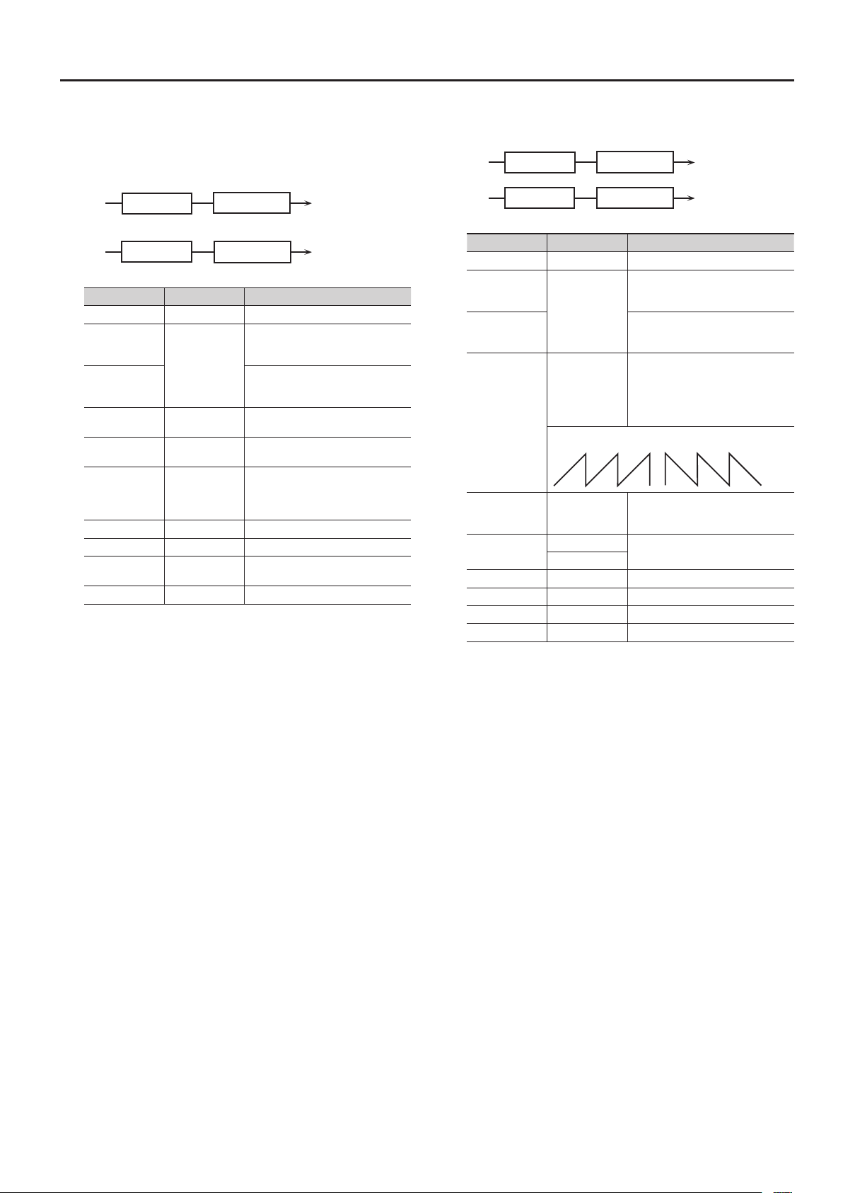
15: TREMOLO
Cyclically modulates the volume to add tremolo eect to the sound.
L in
R in
Parameter Value Explanation
Switch OFF, ON Turns the eect on/o.
Depth Knob
Rate Knob
Mod Wave
Rate (sync sw) # OFF, ON
Rate (Hz) #/
Rate (note) #
Depth # 0–127 Depth to which the eect is applied
Low Gain -15–+15 [dB] Gain of the low range
High Gain -15–+15 [dB] Gain of the high range
Level 0–127 Output Level
Tremolo
Tremolo
RATE,
DEPTH
TRI,
SQR,
SIN,
SAW1,
SAW2
SAW1 SAW2
0.05–10.00 [Hz]
note (p. 31)
2-Band EQ
2-Band EQ
Species the parameter that is
controlled by the MODULATION FX
[DEPTH] knob.
Species the parameter that is
controlled by the MODULATION FX
[RATE] knob.
Modulation wave
TRI: triangle wave
SQR: square wave
SIN: sine wave
SAW1/2: sawtooth wave
If this is ON, the modulation is
synchronized to the tempo of the
rhythm (owner’s manual p. 24).
Frequency of the change
L out
R out
11
Modulation FX Parameters
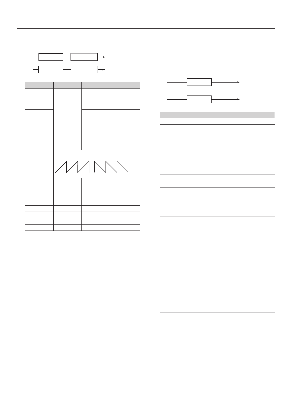
16: AUTO PAN
Cyclically modulates the stereo location of the sound.
L in
R in
Parameter Value Explanation
Switch OFF, ON Turns the eect on/o.
Depth Knob
Rate Knob
Mod Wave
Rate (sync sw) # OFF, ON
Rate (Hz) #/
Rate (note) #
Depth # 0–127 Depth to which the eect is applied
Low Gain -15–+15 [dB] Gain of the low range
High Gain -15–+15 [dB] Gain of the high range
Level 0–127 Output Level
Auto Pan
Auto Pan
RATE, DEPTH
TRI,
SQR,
SIN,
SAW1,
SAW2
SAW1 SAW2
R R
L L
0.05–10.00 [Hz]
note (p. 31)
2-Band EQ
2-Band EQ
Species the parameter that is
controlled by the MODULATION FX
[DEPTH] knob.
Species the parameter that is
controlled by the MODULATION FX
[RATE] knob.
Modulation wave
TRI: triangle wave
SQR: square wave
SIN: sine wave
SAW1/2: sawtooth wave
If this is ON, the modulation is
synchronized to the tempo of the
rhythm (owner’s manual p. 24).
Frequency of the change
L out
R out
17: SLICER
By applying successive cuts to the sound, this eect turns a
conventional sound into a sound that appears to be played as a
backing phrase. This is especially eective when applied to sustaintype sounds.
You can use MFX CONTROL to restart the step sequence from the
beginning (p. 31).
L in
R in
Parameter Value Explanation
Switch OFF, ON Turns the eect on/o.
Depth Knob
Rate Knob
Step 01–16 0–127 Level at each step
Rate (sync sw) # OFF, ON
Rate (Hz) #/
Rate (note) #
Attack # 0–127
Input Sync Sw OFF, ON
Input Sync
Threshold
Mode
Shue # 0–127
Level 0–127 Output level
Slicer
Slicer
RATE,
ATTACK,
SHUFFLE
0.05–10.00 [Hz]
note (p. 31)
0–127
LEGATO,
SLASH
Species the parameter that is
controlled by the MODULATION FX
[DEPTH] knob.
Species the parameter that is
controlled by the MODULATION FX
[RATE] knob.
If this is ON, the modulation is
synchronized to the tempo of the
rhythm (owner’s manual p. 24).
Rate at which the 16-step sequence
will cycle
Speed at which the level changes
between steps
Species whether an input note
will cause the sequence to resume
from the rst step of the sequence
(ON) or not (OFF)
Volume at which an input note will be
detected
Sets the manner in which the volume
changes as one step progresses to
the next.
LEGATO: The change in volume from
one step’s level to the next remains
unaltered. If the level of a following
step is the same as the one preceding
it, there is no change in volume.
SLASH: The level is momentarily
set to 0 before progressing to the
level of the next step. This change
in volume occurs even if the level of
the following step is the same as the
preceding step.
Timing of volume changes in levels for
even-numbered steps (step 2, step 4,
step 6...).
The higher the value, the later the beat
progresses.
L out
R out
12

Modulation FX Parameters
Balance D
Balance D
18: CHORUS
This is a stereo chorus. A lter is provided so that you can adjust the
timbre of the chorus sound.
L in
Chorus
Chorus
R in
Balance D
Parameter Value Explanation
Switch OFF, ON Turns the eect on/o.
Depth Knob
RATE,
BALANCE
Rate Knob
Filter Type
Cuto Freq 200–8000 [Hz] Basic frequency of the lter
Pre Delay 0.0–100 [msec]
Rate (sync sw) # OFF, ON
Rate (Hz) #/
Rate (note) #
Depth 0–127 Depth of modulation
Phase 0–180 [deg] Spatial spread of the sound
Low Gain -15–+15 [dB] Gain of the low range
High Gain -15–+15 [dB] Gain of the high range
Balance #
Level 0–127 Output Level
OFF,
LPF,
HPF
0.05–10.00 [Hz]
note (p. 31)
D100:0W–
D0:100W
Species the parameter that is
controlled by the MODULATION FX
[DEPTH] knob.
Species the parameter that is
controlled by the MODULATION FX
[RATE] knob.
Type of lter
OFF: no lter is used
LPF: cuts the frequency range above
the Cuto Freq
HPF: cuts the frequency range below
the Cuto Freq
Adjusts the delay time from the direct
sound until the chorus sound is heard.
If this is ON, the modulation is
synchronized to the tempo of the
rhythm (owner’s manual p. 24).
Frequency of modulation
Volume balance between the direct
sound (D) and the chorus sound (W)
2-Band
EQ
Balance W
Balance W
2-Band
EQ
L out
R out
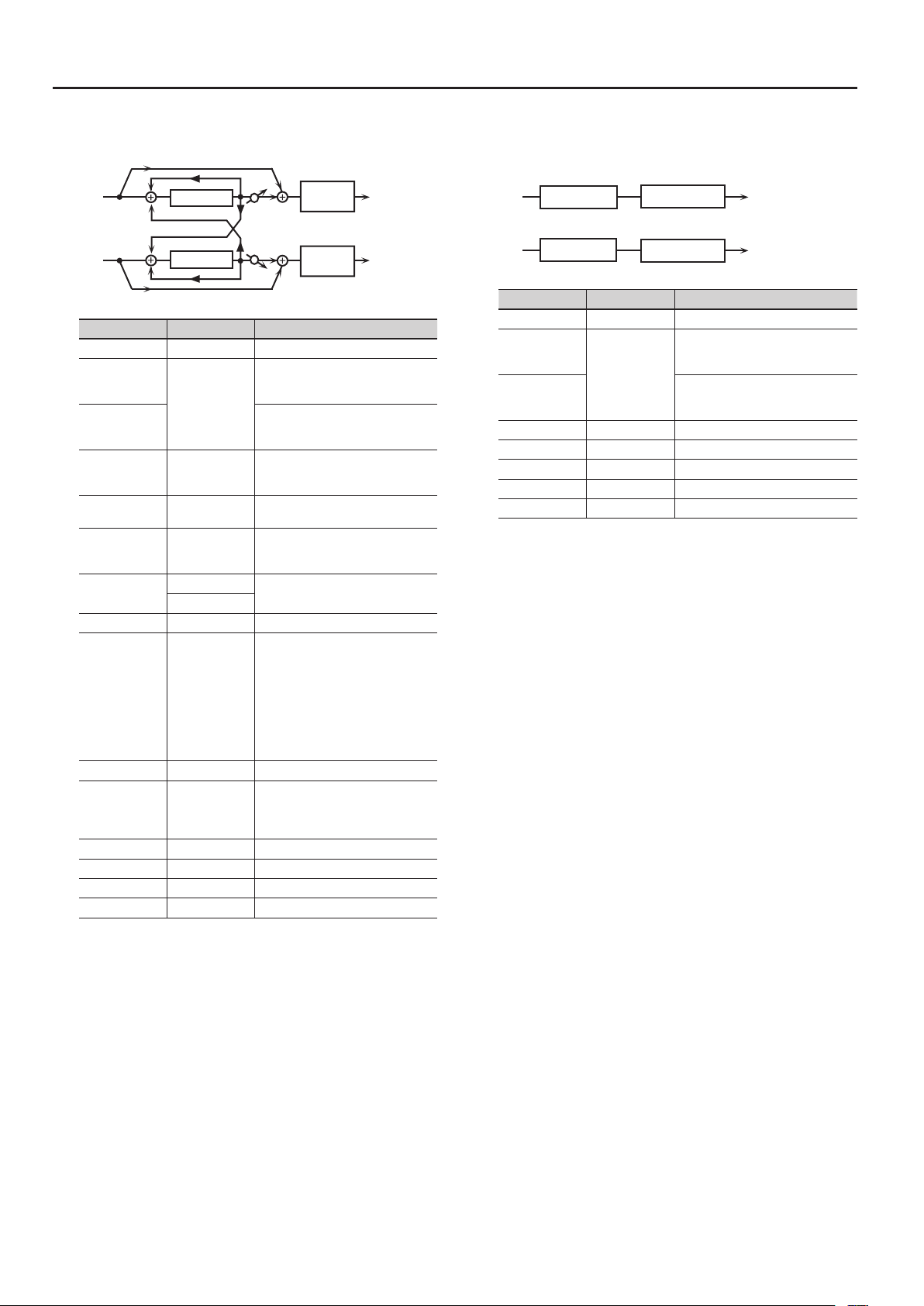
19: FLANGER
This is a stereo anger. (The LFO has the same phase for left and
right.) It produces a metallic resonance that rises and falls like a jet
airplane taking o or landing. A lter is provided so that you can
adjust the timbre of the anged sound.
L in
Flanger
Feedback
Feedback
Flanger
R in
Balance D
Parameter Value Explanation
Switch OFF, ON Turns the eect on/o.
Depth Knob
Rate Knob
Filter Type
Cuto Freq 200–8000 [Hz] Basic frequency of the lter
Pre Delay 0.0–100 [msec]
Rate (sync sw) # OFF, ON
Rate (Hz) #/
Rate (note) #
Depth 0–127 Depth of modulation
Phase 0–180 [deg] Spatial spread of the sound
Feedback # -98–+98 [%]
Low Gain -15–+15 [dB] Gain of the low range
High Gain -15–+15 [dB] Gain of the high range
Balance #
Level 0–127 Output Level
RATE,
FEEDBACK,
BALANCE
OFF,
LPF,
HPF
0.05–10.00 [Hz]
note (p. 31)
D100:0W–
D0:100W
Species the parameter that is
controlled by the MODULATION FX
[DEPTH] knob.
Species the parameter that is
controlled by the MODULATION FX
[RATE] knob.
Type of lter
OFF: no lter is used
LPF: cuts the frequency range above
HPF: cuts the frequency range below
Adjusts the delay time from the direct
sound until the anger sound is heard.
If this is ON, the modulation is
synchronized to the tempo of the
rhythm (owner’s manual p. 24).
Frequency of modulation
Adjusts the proportion of the anger
sound that is fed back into the eect.
Negative “-” settings will invert the
phase.
Volume balance between the direct
sound (D) and the anger sound (W)
2-Band
EQ
Balance W
Balance W
2-Band
EQ
the Cuto Freq
the Cuto Freq
L out
R out
13

Modulation FX Parameters
Balance D
20: STEP FLANGER
This is a anger in which the anger pitch changes in steps. The
speed at which the pitch changes can also be specied in terms of a
note-value of a specied tempo.
L in
Step Flanger
Feedback
Feedback
Step Flanger
R in
Balance D
Parameter Value Explanation
Switch OFF, ON Turns the eect on/o.
Depth Knob
Rate Knob
Filter Type
Cuto Freq 200–8000 [Hz] Basic frequency of the lter
Pre Delay 0.0–100 [msec]
Rate (sync sw) # OFF, ON
Rate (Hz) #/
Rate (note) #
Depth 0–127 Depth of modulation
Phase 0–180 [deg] Spatial spread of the sound
Feedback # -98–+98 [%]
Step Rate
(sync sw) #
Step Rate (Hz) #/
Step Rate (note)#
Low Gain -15–+15 [dB] Gain of the low range
High Gain -15–+15 [dB] Gain of the high range
Balance #
Level 0–127 Output Level
RATE,
FEEDBACK,
STEP RATE,
BALANCE
OFF,
LPF,
HPF
0.05–10.00 [Hz]
note (p. 31)
OFF, ON
0.10–20.00 [Hz]
note (p. 31)
D100:0W–
D0:100W
Species the parameter that is
controlled by the MODULATION FX
[DEPTH] knob.
Species the parameter that is
controlled by the MODULATION FX
[RATE] knob.
Type of lter
OFF: no lter is used
LPF: cuts the frequency range above
HPF: cuts the frequency range below
Adjusts the delay time from the direct
sound until the anger sound is heard.
If this is ON, the modulation is
synchronized to the tempo of the
rhythm (owner’s manual p. 24).
Frequency of modulation
Adjusts the proportion of the anger
sound that is fed back into the eect.
Negative “-” settings will invert the
phase.
If this is ON, the modulation is
synchronized to the tempo of the
rhythm (owner’s manual p. 24).
Rate (period) of pitch change
Volume balance between the direct
sound (D) and the anger sound (W)
2-Band
EQ
Balance W
Balance W
2-Band
EQ
the Cuto Freq
the Cuto Freq
L out
R out
21: HEXA-CHORUS
Uses a six-phase chorus (six layers of chorused sound) to give
richness and spatial spread to the sound.
L in
Balance D
Hexa Chorus
R in
Parameter Value Explanation
Switch OFF, ON Turns the eect on/o.
Depth Knob
Rate Knob
Pre Delay 0.0–100 [msec]
Rate (sync sw) # OFF, ON
Rate (Hz) #/
Rate (note) #
Depth 0–127 Depth of modulation
Pre Delay
Deviation
Depth Deviation -20–+20
Pan Deviation 0–20
Balance #
Level 0–127 Output Level
Balance D
RATE,
BALANCE
0.05–10.00 [Hz]
note (p. 31)
0–20
D100:0W–
D0:100W
Species the parameter that is
controlled by the MODULATION FX
[DEPTH] knob.
Species the parameter that is
controlled by the MODULATION FX
[RATE] knob.
Adjusts the delay time from the direct
sound until the chorus sound is heard.
If this is ON, the modulation is
synchronized to the tempo of the
rhythm (owner’s manual p. 24).
Frequency of modulation
Adjusts the dierences in Pre Delay
between each chorus sound.
Adjusts the dierence in modulation
depth between each chorus sound.
Adjusts the dierence in stereo
location between each chorus sound.
0: All chorus sounds will be in the
20: Each chorus sound will be spaced
Volume balance between the direct
sound (D) and the chorus sound (W)
L out
Balance W
Balance W
R out
center.
at 60 [deg]ree intervals relative to
the center.
14

Modulation FX Parameters
Balance D
22: TREMOLO CHORUS
This is a chorus eect with added Tremolo (cyclic modulation of
volume).
L in
Balance D
Tremolo Chorus
R in
Parameter Value Explanation
Switch OFF, ON Turns the eect on/o.
Depth Knob
Rate Knob
Pre Delay 0.0–100 [msec]
Chorus Rate
(sync sw) #
Chorus Rate
(Hz) #/
Chorus Rate
(note) #
Chorus Depth 0–127 Modulation depth of the chorus eect
Tremolo Rate
(sync sw)
Tremolo Rate
(Hz) #/
Tremolo Rate
(note) #
Tremolo
Separation
Tremolo Phase 0–180 [deg] Spread of the tremolo eect
Balance #
Level 0–127 Output Level
Balance D
Species the parameter that is
CHORUS RATE,
TREMOLO RATE,
BALANCE
OFF, ON
0.05–10.00 [Hz]
note (p. 31)
OFF, ON
0.05–10.00
note (p. 31)
0–127 Spread of the tremolo eect
D100:0W–
D0:100W
controlled by the MODULATION FX
[DEPTH] knob.
Species the parameter that is
controlled by the MODULATION FX
[RATE] knob.
Adjusts the delay time from the direct
sound until the chorus sound is heard.
If this is ON, the modulation is
synchronized to the tempo of the
rhythm (owner’s manual p. 24).
Modulation frequency of the chorus
eect
If this is ON, the modulation is
synchronized to the tempo of the
rhythm (owner’s manual p. 24).
Modulation frequency of the tremolo
eect
Volume balance between the direct
sound (D) and the tremolo chorus
sound (W)
L out
Balance W
Balance W
R out
23: SPACE-D
This is a multiple chorus that applies two-phase modulation in stereo.
It gives no impression of modulation, but produces a transparent
chorus eect.
L in
Space D
Space D
R in
Balance D
Parameter Value Explanation
Switch OFF, ON Turns the eect on/o.
Depth Knob
RATE,
BALANCE
Rate Knob
Pre Delay 0.0–100 [msec]
Rate (sync sw) # OFF, ON
Rate (Hz) #/
Rate (note) #
Depth 0–127 Depth of modulation
Phase 0–180 [deg] Spatial spread of the sound
Low Gain -15–+15 [dB] Gain of the low range
High Gain -15–+15 [dB] Gain of the high range
Balance #
Level 0–127 Output Level
0.05–10.00 [Hz]
note (p. 31)
D100:0W–
D0:100W
Species the parameter that is
controlled by the MODULATION FX
[DEPTH] knob.
Species the parameter that is
controlled by the MODULATION FX
[RATE] knob.
Adjusts the delay time from the direct
sound until the chorus sound is heard.
If this is ON, the modulation is
synchronized to the tempo of the
rhythm (owner’s manual p. 24).
Frequency of modulation
Volume balance between the direct
sound (D) and the chorus sound (W)
2-Band
EQ
Balance W
Balance W
2-Band
EQ
L out
R out
15

Modulation FX Parameters
L in
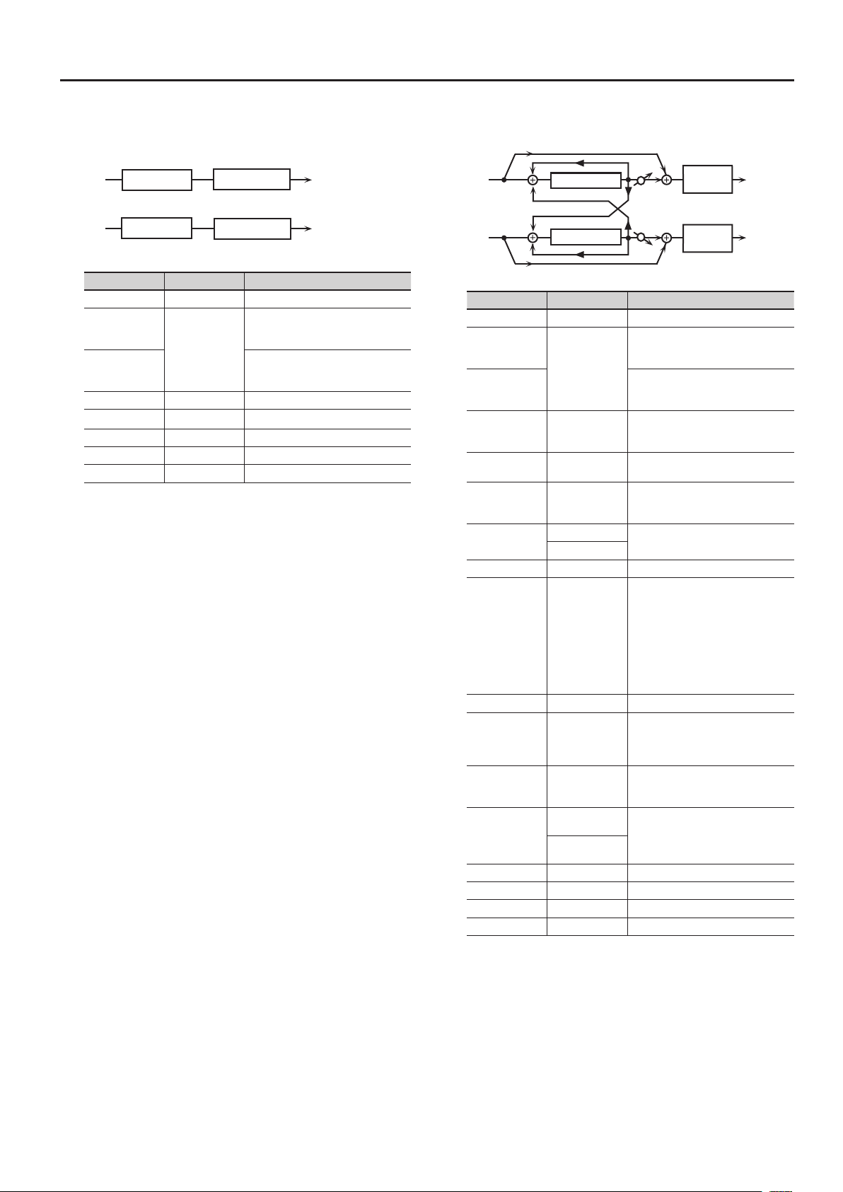
24: OVERDRIVE
This is an overdrive that provides heavy distortion.
Overdrive
Amp
Simulator
R in
Parameter Value Explanation
Switch OFF, ON Turns the eect on/o.
Depth Knob
Rate Knob
Drive # 0–127
Tone # 0–127 Sound quality of the Overdrive eect
Amp Sw OFF, ON Turns the Amp Simulator on/o.
Amp Type
Low Gain -15–+15 [dB] Gain of the low range
High Gain -15–+15 [dB] Gain of the high range
Pan # L64–63R Stereo location of the output sound
Level 0–127 Output Level
DRIVE,
TONE,
PAN
SMALL,
BUILT-IN,
2-STACK,
3-STACK
Species the parameter that is
controlled by the MODULATION FX
[DEPTH] knob.
Species the parameter that is
controlled by the MODULATION FX
[RATE] knob.
Degree of distortion
Also changes the volume.
Type of guitar amp
SMALL: small amp
BUILT-IN: single-unit type amp
2-STACK: large double stack amp
3-STACK: large triple stack amp
2-Band
EQ
Pan L
Pan R
L out
R out
26: T-SCREAM
This models the analog overdrive of the past.
It adds a nice amount of overtones without dirtying the sound.
L in
R in
Parameter Value Explanation
Switch OFF, ON Turns the eect on/o.
Depth Knob
Rate Knob
Distortion 0–127
Tone 0–127 Sound quality of the Overdrive eect
Level # 0–127 Output Level
Overdrive
Overdrive
DISTORTION,
TONE
Tone
Tone
Species the parameter that is
controlled by the MODULATION FX
[DEPTH] knob.
Species the parameter that is
controlled by the MODULATION FX
[RATE] knob.
Degree of distortion
Also changes the volume.
L out
R out
25: DISTORTION
This is a distortion eect that provides heavy distortion. The
parameters are the same as for “24: Overdrive.”
L in
R in
Distortion
Amp
Simulator
2-Band
EQ
L out
Pan L
Pan R
R out
16

Modulation FX Parameters
27: COMPRESSOR
Flattens out high levels and boosts low levels, smoothing out
uctuations in volume.
L in
R in
Compressor
Compressor
Parameter Value Explanation
Switch OFF, ON Turns the eect on/o.
Depth Knob
Rate Knob
Attack # 0–127
Threshold # 0–127
Post Gain 0–+18 [dB] Adjusts the output gain.
Low Gain -15–+15 [dB] Gain of the low frequency range
High Gain -15–+15 [dB] Gain of the high frequency range
Level # 0–127 Output Level
ATTACK,
THRESHOLD,
LEVEL
2-Band EQ
2-Band EQ
Species the parameter that is
controlled by the MODULATION FX
[DEPTH] knob.
Species the parameter that is
controlled by the MODULATION FX
[RATE] knob.
Sets the time it takes until the level is
compressed after the input exceeds
the Threshold.
Adjusts the volume at which compression begins
L out
R out
28: LIMITER
Compresses signals that exceed a specied volume level, preventing
distortion from occurring.
L in
R in
Parameter Value Explanation
Switch OFF, ON Turns the eect on/o.
Depth Knob
Rate Knob
Release # 0–127
Threshold # 0–127
Ratio
Post Gain 0–+18 [dB] Adjusts the output gain.
Low Gain -15–+15 [dB] Gain of the low frequency range
High Gain -15–+15 [dB] Gain of the high frequency range
Level # 0–127 Output Level
Limiter
Limiter
RELEASE,
THRESHOLD,
LEVEL
1.5:1, 2:1, 4:1,
100:1
2-Band EQ
2-Band EQ
Species the parameter that is
controlled by the MODULATION FX
[DEPTH] knob.
Species the parameter that is
controlled by the MODULATION FX
[RATE] knob.
Adjusts the time after the signal
volume falls below the Threshold Level
until compression is no longer applied.
Adjusts the volume at which compression begins
Compression ratio
L out
R out
17

Modulation FX Parameters
29: SUSTAINER
This eect compresses high input and boosts low input, making the
volume consistent and producing undistorted sustain.
L in
R in
Parameter Value Explanation
Switch OFF, ON Turns the eect on/o.
Depth Knob
Rate Knob
Sustain # 0–127
Attack 0–127 Time until the volume is compressed
Release 0–127 Time until compression ends
Post Gain -15–+15 [dB] Adjusts the output gain.
Low Gain -15–+15 [dB] Gain of the low frequency range
High Gain -15–+15 [dB] Gain of the high frequency range
Level # 0–127 Output Level
Sustainer
Sustainer
SUSTAIN,
ATTACK,
RELEASE,
LEVEL
2-Band EQ
2-Band EQ
Species the parameter that is
controlled by the MODULATION FX
[DEPTH] knob.
Species the parameter that is
controlled by the MODULATION FX
[RATE] knob.
Adjusts the range of volume for which
low input signals are boosted to make
the volume consistent.
Higher settings produce longer
sustain.
L out
R out
30: GATE
Cuts the reverb’s delay according to the volume of the sound
sent into the eect. Use this when you want to create an articialsounding decrease in the reverb’s decay.
L in
R in
Parameter Value Explanation
Switch OFF, ON Turns the eect on/o.
Depth Knob
Rate Knob
Threshold # 0–127
Mode GATE, DUCK
Attack 0–127
Hold 0–127
Release 0–127
Balance #
Level 0–127 Output Level
Gate
Gate
THRESHOLD,
BALANCE
D100:0W–
D0:100W
Species the parameter that is
controlled by the MODULATION FX
[DEPTH] knob.
Species the parameter that is
controlled by the MODULATION FX
[RATE] knob.
Volume level at which the gate begins
to close
Type of gate
GATE: The gate will close when
the volume of the original sound
decreases, cutting the original sound.
DUCK (Ducking): The gate will close
when the volume of the original
sound increases, cutting the original
sound.
Adjusts the time it takes for the gate to
fully open after being triggered.
Adjusts the time it takes for the gate
to start closing after the source sound
falls beneath the Threshold.
Adjusts the time it takes the gate to
fully close after the hold time.
Volume balance between the direct
sound (D) and the eect sound (W)
L out
R out
18

Modulation FX Parameters
Balance D
Balance D
Balance D
Balance D
31: DELAY
This is a stereo delay.
When Feedback Mode is NORMAL:
L in
Delay
Feedback
Feedback
Delay
R in
Balance D
When Feedback Mode is CROSS:
L in
Delay
Feedback
Feedback
Delay
R in
Balance D
Parameter Value Explanation
Switch OFF, ON Turns the eect on/o.
Depth Knob
FEEDBACK,
BALANCE
Rate Knob
Delay Left
(sync switch)
Delay Left
(msec)/
Delay Left (note)
Delay Right
(sync switch)
Delay Right
(msec)/
Delay Right
(note)
Phase Left
Phase Right
Feedback Mode NORMAL, CROSS
Feedback # -98–+98 [%]
HF Damp
Low Gain -15–+15 [dB] Gain of the low frequency range
High Gain -15–+15 [dB] Gain of the high frequency range
Balance #
Level 0–127 Output Level
OFF, ON
1–1300 [msec]
note (p. 31)
OFF, ON
1–1300 [msec]
note (p. 31)
NORMAL,
INVERSE
200–8000 [Hz],
BYPASS
D100:0W–
D0:100W
Species the parameter that is
controlled by the MODULATION FX
[DEPTH] knob.
Species the parameter that is
controlled by the MODULATION FX
[RATE] knob.
If this is ON, the modulation is
synchronized to the tempo of the
rhythm (owner’s manual p. 24).
Delay time from the original sound
until the left delay sound is heard
If this is ON, the modulation is
synchronized to the tempo of the
rhythm (owner’s manual p. 24).
Delay time from the original sound
until the right delay sound is heard
Phase of the delay sound
Selects the way in which delay sound
is fed back into the eect. (See the
gures above.)
Adjusts the amount of the delay
sound that’s fed back into the eect.
Negative “-” settings invert the phase.
Adjusts the frequency above which
sound fed back to the eect is ltered
out (BYPASS: no cut).
Volume balance between the direct
sound (D) and the delay sound (W)
2-Band
EQ
Balance W
Balance W
2-Band
EQ
2-Band
EQ
Balance W
Balance W
2-Band
EQ
L out
R out
L out
R out
32: MODULATION DELAY
Adds modulation to the delayed sound.
When Feedback Mode is NORMAL:
L in L out
Delay
Feedback
Feedback
Delay
R in R out
Modulation
Modulation
Balance D
When Feedback Mode is CROSS:
L in
Delay
R in
Parameter Value Explanation
Switch OFF, ON Turns the eect on/o.
Depth Knob
Rate Knob
Delay Left
(sync switch)
Delay Left
(msec)/
Delay Left (note)
Delay Right
(sync switch)
Delay Right
(msec)/
Delay Right
(note)
Feedback Mode NORMAL, CROSS
Feedback # -98–+98 [%]
HF Damp
Rate # OFF, ON
Rate (Hz) #/
Rate (note) #
Depth 0–127 Depth of modulation
Phase 0–180 [deg] Spatial spread of the sound
Low Gain -15–+15 [dB] Gain of the low frequency range
High Gain -15–+15 [dB] Gain of the high frequency range
Balance #
Level 0–127 Output Level
Feedback
Feedback
Delay
Modulation
Modulation
Balance D
FEEDBACK,
RATE,
BALANCE
OFF, ON
1–1300 [msec]
note (p. 31)
OFF, ON
1–1300 [msec]
note (p. 31)
200–8000 [Hz],
BYPASS
0.05–10.00 [Hz]
note (p. 31)
D100:0W–
D0:100W
2-Band
EQ
Balance W
Balance W
2-Band
EQ
2-Band
EQ
Balance W
Balance W
2-Band
EQ
Species the parameter that is
controlled by the MODULATION FX
[DEPTH] knob.
Species the parameter that is
controlled by the MODULATION FX
[RATE] knob.
If this is ON, the modulation is
synchronized to the tempo of the
rhythm (owner’s manual p. 24).
Delay time from the original sound
until the left delay sound is heard
If this is ON, the modulation is
synchronized to the tempo of the
rhythm (owner’s manual p. 24).
Delay time from the original sound
until the right delay sound is heard
Selects the way in which delay sound
is fed back into the eect (See the
gures above.)
Adjusts the amount of the delay
sound that’s fed back into the eect.
Negative “-” settings invert the phase.
Adjusts the frequency above which
sound fed back to the eect is ltered
out (BYPASS: no cut).
If this is ON, the modulation is
synchronized to the tempo of the
rhythm (owner’s manual p. 24).
Frequency of modulation
Volume balance between the direct
sound (D) and the delay sound (W)
L out
R out
19

Modulation FX Parameters
33: 3TAP PAN DELAY
Produces three delay sounds; center, left and right.
Balance D
L in
Left Tap
Triple Tap Delay
Feedback
Center Tap
Right Tap
R in
Balance D
Parameter Value Explanation
Switch OFF, ON Turns the eect on/o.
Depth Knob
Rate Knob
Delay Left/Right/
Center (sync sw)
Delay Left/Right/
Center (msec) #/
Delay Left/Right/
Center (note) #
Center Feedback
#
HF Damp
Left/Right/
Center Level
Low Gain -15–+15 [dB] Gain of the low frequency range
High Gain -15–+15 [dB] Gain of the high frequency range
Balance #
Level 0–127 Output Level
CENTER
FEEDBACK,
BALANCE
OFF, ON
1–2600 [msec]
note (p. 31)
-98–+98 [%]
200–8000 [Hz],
BYPASS
0–127 Volume of each delay
D100:0W–
D0:100W
Species the parameter that is
controlled by the MODULATION FX
[DEPTH] knob.
Species the parameter that is
controlled by the MODULATION FX
[RATE] knob.
If this is ON, the modulation is
synchronized to the tempo of the
rhythm (owner’s manual p. 24).
Adjusts the time until the delay sound
is heard.
Adjusts the amount of the delay
sound that’s fed back into the eect.
Negative “-” settings invert the phase.
Adjusts the frequency above which
sound fed back to the eect is ltered
out (BYPASS: no cut).
Volume balance between the direct
sound (D) and the delay sound (W)
Balance W
Balance W
2-Band
EQ
2-Band
EQ
L out
R out
34: 4TAP PAN DELAY
This eect has four delays.
Balance D
L in
Feedback
Quadruple Tap Delay
R in
2 3
1
L
Parameter Value Explanation
Switch OFF, ON Turns the eect on/o.
Depth Knob
Rate Knob
Delay 1–4 Time
(sync sw)
Delay 1–4 Time
(msec)/
Delay 1–4 Time
(note)
Delay 1
Feedback #
HF Damp
Delay 1–4 Level 0–127 Volume of each delay
Low Gain -15–+15 [dB] Gain of the low frequency range
High Gain -15–+15 [dB] Gain of the high frequency range
Balance #
Level 0–127 Output Level
4
R
DLY 1 FBACK,
BALANCE
OFF, ON
1–2600 [msec]
note (p. 31)
-98–+98 [%]
200–8000 [Hz],
BYPASS
D100:0W–
D0:100W
Delay 1
Delay 2
Delay 3
Delay 4
Balance D
Species the parameter that is
controlled by the MODULATION FX
[DEPTH] knob.
Species the parameter that is
controlled by the MODULATION FX
[RATE] knob.
If this is ON, the modulation is
synchronized to the tempo of the
rhythm (owner’s manual p. 24).
Adjusts the time until the delay 1–4
sound is heard.
Adjusts the amount of the delay
sound that’s fed back into the eect.
Negative “-” settings invert the phase.
Adjusts the frequency above which
sound fed back to the eect is ltered
out (BYPASS: no cut).
Volume balance between the direct
sound (D) and the delay sound (W)
L out
Balance W
Balance W
R out
20

Modulation FX Parameters
Balance D
35: MULTI TAP DELAY
This eect provides four delays. Each of the Delay Time parameters
can be set to a note length based on the selected tempo. You can also
set the panning and level of each delay sound.
L in
Feed
back
Delay 1
Delay 3
Multi Tap Delay
Delay 4
Delay 2
R in
Parameter Value Explanation
Switch OFF, ON Turns the eect on/o.
Depth Knob
DLY 1 FBACK,
BALANCE
Rate Knob
Delay 1–4
(sync sw)
Delay 1–4 Time
(msec)/
Delay 1–4 Time
(note)
Delay 1
Feedback #
HF Damp
Delay 1–4 Pan L64–63R Stereo location of Delays 1–4
Delay 1–4 Level 0–127 Output level of Delays 1–4
Low Gain -15–+15 [dB] Gain of the low frequency range
High Gain -15–+15 [dB] Gain of the high frequency range
Balance #
Level 0–127 Output Level
OFF, ON
1–2600 [msec]
note (p. 31)
-98–+98 [%]
200–8000 [Hz],
BYPASS
D100:0W–
D0:100W
Balance D
Species the parameter that is
controlled by the MODULATION FX
[DEPTH] knob.
Species the parameter that is
controlled by the MODULATION FX
[RATE] knob.
If this is ON, the modulation is
synchronized to the tempo of the
rhythm (owner’s manual p. 24).
Adjusts the time until Delays 1–4 are
heard.
Adjusts the amount of the delay
sound that’s fed back into the eect.
Negative “-” settings invert the phase.
Adjusts the frequency above which
sound fed back to the eect is ltered
out (BYPASS: no cut).
Volume balance between the direct
sound (D) and the eect sound (W)
2-Band
EQ
Balance W
Balance W
2-Band
EQ
L out
R out
36: REVERSE DELAY
This is a reverse delay that adds a reversed and delayed sound to the
input sound. A tap delay is connected immediately after the reverse
delay.
L in
Feedback
Rev. Delay
Rev
Delay
D3
D1
D2
R in
Parameter Value Explanation
Switch OFF, ON Turns the eect on/o.
Depth Knob
Rate Knob
Threshold 0–127
Rev Delay Tme
(sync sw)
Rev Delay Tme
(msec)/
Rev Delay Tme
(note)
Rev Delay
Feedback #
Rev Delay HF
Damp
Rev Delay Pan L64–63R Panning of the reverse delay sound
Rev Delay Level 0–127 Volume of the reverse delay sound
Delay 1–3 Time
(sync sw)
Delay 1–3 Time
(msec)/
Delay 1–3 Time
(note)
Delay 3
Feedback #
Delay HF Damp
Delay 1 Pan,
Delay 2 Pan
Delay 1 Level,
Delay 2 Level
Low Gain -15–+15 [dB] Gain of the low frequency range
High Gain -15–+15 [dB] Gain of the high frequency range
Balance #
Level 0–127 Output Level
REV DLY
FEEDBACK,
DLY 3 FEEDBACK,
BALANCE
OFF, ON
1–1300 [msec]
note (p. 31)
-98–+98 [%]
200–8000 [Hz],
BYPASS
OFF, ON
1–1300 [msec]
note (p. 31)
-98–+98 [%]
200–8000 [Hz],
BYPASS
L64–63R Panning of the tap delay sounds
0–127 Volume of the tap delay sounds
D100:0W–
D0:100W
Species the parameter that is
controlled by the MODULATION FX
[DEPTH] knob.
Species the parameter that is
controlled by the MODULATION FX
[RATE] knob.
Volume at which the reverse delay will
begin to be applied
If this is ON, the modulation is
synchronized to the tempo of the
rhythm (owner’s manual p. 24).
Delay time from when sound is input
into the reverse delay until the delay
sound is heard
Proportion of the delay sound that
is to be returned to the input of the
reverse delay (negative values invert
the phase)
Frequency at which the high-frequency content of the reverse-delayed
sound will be cut (BYPASS: no cut).
If this is ON, the modulation is
synchronized to the tempo of the
rhythm (owner’s manual p. 24).
Delay time from when sound is input
into the tap delay until the delay
sound is heard
Proportion of the delay sound that
is to be returned to the input of the
tap delay (negative values invert the
phase)
Frequency at which the low-frequency
content of the tap delay sound will be
cut (BYPASS: no cut).
Volume balance of the original sound
(D) and delay sound (W)
2-Band
EQ
2-Band
EQ
L out
R out
21

Modulation FX Parameters
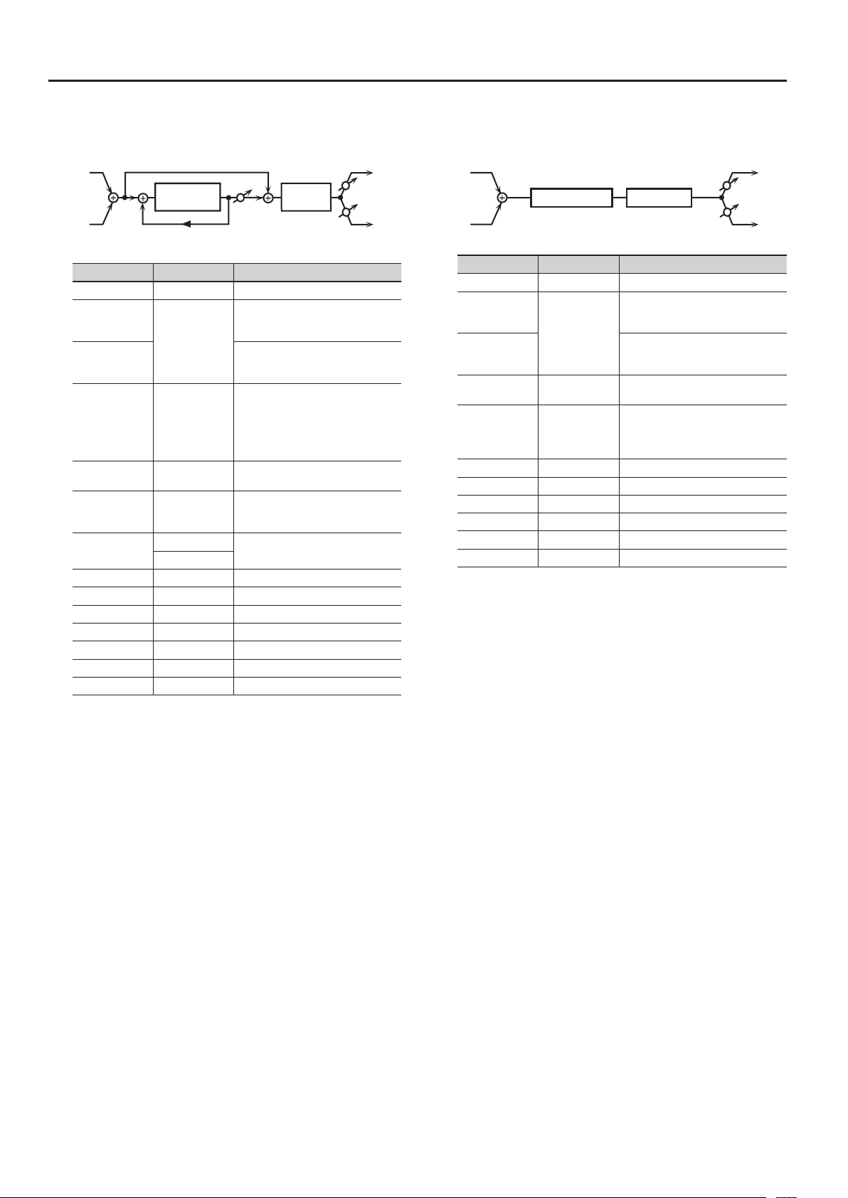
37: TIME CTRL DELAY
A stereo delay in which the delay time can be varied smoothly.
L in
Time Ctrl Delay
Feedback
Feedback
Time Ctrl Delay
R in
Parameter Value Explanation
Switch OFF, ON Turns the eect on/o.
Depth Knob
Rate Knob
Delay Time
(sync sw) #
Delay Time
(msec) #/
Delay Time
(note) #
Acceleration 0–15
Feedback # -98–+98 [%]
HF Damp
Low Gain -15–+15 [dB] Gain of the low frequency range
High Gain -15–+15 [dB] Gain of the high frequency range
Balance #
Level 0–127 Output Level
DELAY TIME,
FEEDBACK,
BALANCE
OFF, ON
1–1300 [msec]
note (p. 31)
200–8000 [Hz],
BYPASS
D100:0W–
D0:100W
Balance D
2-Band EQ
Balance W
Balance W
Balance D
Species the parameter that is
controlled by the MODULATION FX
[DEPTH] knob.
Species the parameter that is
controlled by the MODULATION FX
[RATE] knob.
If this is ON, the modulation is
synchronized to the tempo of the
rhythm (owner’s manual p. 24).
Adjusts the time until the delay is
heard.
Adjusts the speed which the Delay
Time changes from the current setting
to a specied new setting.
The rate of change for the Delay
Time directly aects the rate of pitch
change.
Adjusts the amount of the delay
sound that’s fed back into the eect.
Negative “-” settings invert the phase.
Adjusts the frequency above which
sound fed back to the eect is ltered
out (BYPASS: no cut).
Volume balance between the direct
sound (D) and the delay sound (W)
2-Band EQ
L out
R out
38: TAPE ECHO
A virtual tape echo that produces a realistic tape delay sound. This
simulates the tape echo section of a Roland RE-201 Space Echo.
L in
Direct Level
Tape Echo
R in
Parameter Value Explanation
Switch OFF, ON Turns the eect on/o.
Depth Knob
Rate Knob
Mode
Repeat Rate # 0–127
Intensity # 0–127 Amount of delay repeats
Bass -15–+15 [dB]
Treble -15–+15 [dB]
Head S Pan
Head M Pan
Head L Pan
Tape Distortion 0–5
W/F Rate 0–127
W/F Depth 0–127 Depth of wow/utter
Echo Level # 0–127 Volume of the echo sound
Direct Level # 0–127 Volume of the original sound
Level 0–127 Output level
Direct Level
REPEAT RATE,
INTENSITY,
ECHO LEVEL,
DIRECT LEVEL
S, M, L, S+M, S+L,
M+L, S+M+L
L64–63R
Species the parameter that is
controlled by the MODULATION FX
[DEPTH] knob.
Species the parameter that is
controlled by the MODULATION FX
[RATE] knob.
Combination of playback heads to use
Select from three dierent heads with
dierent delay times.
S: short
M: middle
L: long
Tape speed
Increasing this value will shorten the
spacing of the delayed sounds.
Boost/cut for the lower range of the
echo sound
Boost/cut for the upper range of the
echo sound
Independent panning for the short,
middle, and long playback heads
Amount of tape-dependent distortion
to be added
This simulates the slight tonal changes
that can be detected by signal-analysis
equipment. Increasing this value will
increase the distortion.
Speed of wow/utter (complex
variation in pitch caused by tape wear
and rotational irregularity)
L out
Echo Level
Echo Level
R out
22

Modulation FX Parameters
39: LOFI COMPRESS
This is an eect that intentionally degrades the sound quality for
creative purposes.
L in
R in
Compressor
Compressor
Parameter Value Explanation
Switch OFF, ON Turns the eect on/o.
Depth Knob
BALANCE,
LEVEL
Rate Knob
Pre Filt Type 1–6
LoFi Type 1–9
Post Filter Type OFF, LPF, HPF
Post Filter Cuto 200–8000 [Hz] Basic frequency of the Post Filter
Low Gain -15–+15 [dB] Gain of the low range
High Gain -15–+15 [dB] Gain of the high range
Balance #
Level # 0–127 Output Level
D100:0W–
D0:100W
Lo-Fi
Lo-Fi
Species the parameter that is
controlled by the MODULATION FX
[DEPTH] knob.
Species the parameter that is
controlled by the MODULATION FX
[RATE] knob.
Selects the type of lter applied to the
sound before it passes through the
Lo-Fi eect.
1: Compressor o
2–6: Compressor on
Degrades the sound quality. The
sound quality grows poorer as this
value is increased.
Type of lter
OFF: no lter is used
LPF: cuts the frequency range above
the Cuto
HPF: cuts the frequency range below
the Cuto
Volume balance between the direct
sound (D) and the eect sound (W)
2-Band
EQ
2-Band
EQ
L out
R out
40: BIT CRUSHER
This creates a lo- sound.
L in
R in
Parameter Value Explanation
Switch OFF, ON Turns the eect on/o.
Depth Knob
Rate Knob
Sample Rate # 0–127 Adjusts the sample rate.
Bit Down # 0–20 Adjusts the bit depth.
Filter # 0–127 Adjusts the lter depth.
Low Gain -15–+15 [dB] Gain of the low frequency range
High Gain -15–+15 [dB] Gain of the high frequency range
Level 0–127 Output Level
Bit Crusher
Bit Crusher
SAMPLE RATE,
BIT DOWN,
FILTER
2-Band EQ
2-Band EQ
Species the parameter that is
controlled by the MODULATION FX
[DEPTH] knob.
Species the parameter that is
controlled by the MODULATION FX
[RATE] knob.
L out
R out
23

Modulation FX Parameters
Balance D
41: PITCH SHIFTER
A stereo pitch shifter.
L in
Pitch Shifter
Pitch Shifter
R in
Parameter Value Explanation
Switch OFF, ON Turns the eect on/o.
Depth Knob
Rate Knob
Coarse #1 -24–+12 [semi]
Fine #1 -100–+100 [cent]
Delay Time
(sync sw)
Delay Time
(msec)/
Delay Time
(note)
Feedback # -98–+98 [%]
Low Gain -15–+15 [dB] Gain of the low range
High Gain -15–+15 [dB] Gain of the high range
Balance #
Level 0–127 Output Level
COARSE,
FINE,
FEEDBACK,
BALANCE
OFF, ON
1–1300 [msec]
note (p. 31)
D100:0W–
D0:100W
Species the parameter that is
controlled by the MODULATION FX
[DEPTH] knob.
Species the parameter that is
controlled by the MODULATION FX
[RATE] knob.
Adjusts the pitch of the pitch shifted
sound in semitone steps.
Adjusts the pitch of the pitch shifted
sound in 2-cent steps.
If this is ON, the modulation is
synchronized to the tempo of the
rhythm (owner’s manual p. 24).
Adjusts the delay time from the direct
sound until the pitch shifted sound
is heard.
Adjusts the proportion of the pitch
shifted sound that is fed back into the
eect. Negative “-” settings will invert
the phase.
Volume balance between the direct
sound (D) and the pitch shifted sound
(W)
2-Band EQ
2-Band EQ
L out
R out
42: 2VOICE PITCH SHIFTER
Shifts the pitch of the original sound. This 2-voice pitch shifter has
two pitch shifters, and can add two pitch shifted sounds to the
original sound.
L in
R in
Parameter Value Explanation
Switch OFF, ON Turns the eect on/o.
Depth Knob
Rate Knob
Pitch1 Coarse #1 -24–+12 semi
Pitch1 Fine #1 -100–+100 cent
Pitch1 Delay
(sync sw)
Pitch1 Delay
(msec)/
Pitch1 Delay
(note)
Pitch1 Feedback
#
Pitch1 Pan # L64–63R
Pitch1 Level 0–127 Volume of the Pitch Shift 1 sound
Pitch2 Coarse #2 -24–+12 semi
Pitch2 Fine #2 -100–+100 cent
Pitch2 Delay OFF, ON
Pitch2 Delay
(msec)/
Pitch2 Delay
(note)
Pitch2 Feedback
#
Pitch2 Pan # L64–63R
Pitch2 Level 0–127
Low Gain -15–+15 [dB] Gain of the low range
High Gain -15–+15 [dB] Gain of the high range
Balance #
Level 0–127 Output Level
Level 1
2Voice
Pitch Shifter
Level 2
PITCH1 COARSE,
PITCH1 FINE,
PITCH1
FEEDBACK,
PITCH1 PAN,
PITCH2 COARSE,
PITCH2 FINE,
PITCH2
FEEDBACK,
PITCH2 PAN,
BALANCE
OFF, ON
1–1300 [msec]
note (p. 31)
-98–+98 [%]
1–1300 [msec]
note (p. 31)
-98–+98 [%]
D100:0W–
D0:100W
Pan 1 L
Pan 1 R
Pan 2 L
Pan 2 R
Balance D
Species the parameter that is
controlled by the MODULATION FX
[DEPTH] knob.
Species the parameter that is
controlled by the MODULATION FX
[RATE] knob.
Adjusts the pitch of Pitch Shift 1 in
semitone steps.
Adjusts the pitch of Pitch Shift Pitch 1
in 2-cent steps.
If this is ON, the modulation is
synchronized to the tempo of the
rhythm (owner’s manual p. 24).
Adjusts the delay time from the direct
sound until the Pitch Shift 1 sound is
heard.
Adjusts the proportion of the pitch
shifted sound that is fed back into the
eect. Negative “-” settings will invert
the phase.
Stereo location of the Pitch Shift 1
sound
Settings of the Pitch Shift 2 sound.
The parameters are the same as for the
Pitch Shift 1 sound.
Volume balance between the direct
sound (D) and the pitch shifted sound
(W)
2-Band
Balance W
Balance W
2-Band
EQ
EQ
L out
R out
24

Modulation FX Parameters
43: OD " CHORUS
L in
Overdrive
R in
Parameter Value Explanation
Switch OFF, ON Turns the eect on/o.
Depth Knob
Rate Knob
Overdrive
Drive #
Overdrive Pan # L64–63R Stereo location of the overdrive sound
Chorus Pre Delay 0.0–100.0 [msec]
Chorus Rate
(sync sw) #
Chorus Rate
(Hz) #/
Chorus Rate
(note) #
Chorus Depth 0–127 Depth of modulation
Chorus Balance #
Level 0–127 Output Level
OVERDRIVE
DRIVE,
OVERDRIVE PAN,
CHORUS RATE,
CHORUS
BALANCE
0–127
OFF, ON
0.05–10.00 [Hz]
note (p. 31)
D100:0W–
D0:100W
Balance D
Chorus
Balance D
Species the parameter that is
controlled by the MODULATION FX
[DEPTH] knob.
Species the parameter that is
controlled by the MODULATION FX
[RATE] knob.
Degree of distortion
Also changes the volume.
Adjusts the delay time from the direct
sound until the chorus sound is heard.
If this is ON, the modulation is
synchronized to the tempo of the
rhythm (owner’s manual p. 24).
Frequency of modulation
Adjusts the volume balance between
the sound that is sent through the
chorus (W) and the sound that is not
sent through the chorus (D).
L out
Balance W
Balance W
R out
44: OD " FLANGER
L in
Overdrive
R in
Parameter Value Explanation
Switch OFF, ON Turns the eect on/o.
Depth Knob
Rate Knob
Overdrive
Drive #
Overdrive Pan # L64–63R Stereo location of the overdrive sound
Flanger Pre
Delay
Flanger Rate
(sync sw) #
Flanger Rate
(Hz) #/
Flanger Rate
(note) #
Flanger Depth 0–127 Depth of modulation
Flanger
Feedback #
Flanger Balance #D100:0W–
Level 0–127 Output Level
OVERDRIVE
DRIVE,
OVERDRIVE PAN,
FLN RATE,
FLN FEEDBACK,
FLN BALANCE
0–127
0.0–100 [msec]
OFF, ON
0.05–10.00 [Hz]
note (p. 31)
-98–+98 [%]
D0:100W
Balance D
Feedback
Balance W
Flanger
Balance W
Balance D
Species the parameter that is
controlled by the MODULATION FX
[DEPTH] knob.
Species the parameter that is
controlled by the MODULATION FX
[RATE] knob.
Degree of distortion
Also changes the volume.
Adjusts the delay time from the direct
sound until the anger sound is heard.
If this is ON, the modulation is
synchronized to the tempo of the
rhythm (owner’s manual p. 24).
Frequency of modulation
Adjusts the proportion of the anger
sound that is fed back into the eect.
Negative “-” settings will invert the
phase.
Adjusts the volume balance between
the sound that is sent through the
anger (W) and the sound that is not
sent through the anger (D).
L out
R out
25

Modulation FX Parameters
45: OD " DELAY
L in
Overdrive
R in
Parameter Value Explanation
Switch OFF, ON Turns the eect on/o.
Depth Knob
Rate Knob
Overdrive
Drive #
Overdrive Pan # L64–63R Stereo location of the overdrive sound
Delay Time
(sync sw)
Delay Time
(msec)/
Delay Time
(note)
Delay Feedback
#
Delay HF Damp
Delay Balance #
Level 0–127 Output Level
OVERDRIVE
DRIVE,
OVERDRIVE PAN,
DELAY
FEEDBACK,
DELAY BALANCE
0–127
OFF, ON
1–2600 [msec]
note (p. 31)
-98–+98 [%]
200–8000 [Hz],
BYPASS
D100:0W–
D0:100W
Balance D
Balance W
Delay
Feedback
Balance D
Species the parameter that is
controlled by the MODULATION FX
[DEPTH] knob.
Species the parameter that is
controlled by the MODULATION FX
[RATE] knob.
Degree of distortion
Also changes the volume.
If this is ON, the modulation is
synchronized to the tempo of the
rhythm (owner’s manual p. 24).
Adjusts the delay time from the direct
sound until the delay sound is heard.
Adjusts the proportion of the delay
sound that is fed back into the eect.
Negative “-” settings will invert the
phase.
Adjusts the frequency above which
sound fed back to the eect will be cut
(BYPASS: no cut).
Adjusts the volume balance between
the sound that is sent through the
delay (W) and the sound that is not
sent through the delay (D).
Balance W
L out
R out
46: DS " CHORUS
The parameters are essentially the same as in “43: OD " CHORUS,”
with the exception of the following two.
• Overdrive Drive " Distortion Drive
• Overdrive Pan " Distortion Pan
L in
R in
Distortion
Balance D
Chorus
Balance D
L out
Balance W
Balance W
R out
47: DS " FLANGER
The parameters are essentially the same as in “44: OD " FLANGER,”
with the exception of the following two.
• Overdrive Drive " Distortion Drive
• Overdrive Pan " Distortion Pan
L in
R in
Distortion
Balance D
Feedback
Flanger
Balance D
L out
Balance W
Balance W
R out
48: DS " DELAY
The parameters are essentially the same as in “45: OD " DELAY,” with
the exception of the following two.
• Overdrive Drive " Distortion Drive
• Overdrive Pan " Distortion Pan
L in
R in
Distortion
Balance D
Delay
Feedback
Balance D
L out
Balance W
Balance W
R out
26

Modulation FX Parameters
L in
L in
49: OD/DS " TWAH
Overdrive/
Distortion
Amp
Simulator
Touch
Wah
R in
Parameter Value Explanation
Switch OFF, ON Turns the eect on/o.
Depth Knob
Rate Knob
Drive Switch OFF, ON Turns overdrive/distortion on/o
Drive Type
Drive # 0–127
Tone # 0–127 Sound quality of the Overdrive eect
Amp Switch OFF, ON Turns the Amp Simulator on/o.
Amp Type
TWah Switch OFF, ON Wah on/o
TWah Filter Type LPF, BPF
TWah Polarity DOWN, UP
TWah Sens # 0–127
TWah Manual # 0–127
TWah Peak # 0–127
TWah Balance #
Low Gain -15–+15 [dB] Gain of the low range
High Gain -15–+15 [dB] Gain of the high range
Level 0–127 Output Level
DRIVE,
TONE,
TWAH SENS,
TWAH MANUAL,
TWAH PEAK,
TWAH BALANCE
OVERDRIVE,
DISTORTION
SMALL,
BUILTIN,
2-STACK,
3-STACK
D100:0W–
D0:100W
Species the parameter that is
controlled by the MODULATION FX
[DEPTH] knob.
Species the parameter that is
controlled by the MODULATION FX
[RATE] knob.
Type of distortion
Degree of distortion
Also changes the volume.
Type of guitar amp
SMALL: small amp
BUILT-IN: single-unit type amp
2-STACK: large double stack amp
3-STACK: large triple stack amp
Type of lter
LPF: Produces a wah eect in a broad
frequency range.
BPF: Produces a wah eect in a narrow
frequency range.
Direction in which the lter will move
UP: Move toward a higher frequency
DOWN: Move toward a lower
frequency
Sensitivity with which the lter is
modied
Basic frequency at which the wah
eect is applied
Width of the frequency region at
which the wah eect is applied
Increasing this value will make the
frequency region narrower.
Volume balance of the sound that
passes through the wah (W) and the
direct sound (D)
2-Band
EQ
L out
R out
50: OD/DS " AWAH
Overdrive/
Distortion
Amp
Simulator
Auto
Wah
R in
Parameter Value Explanation
Switch OFF, ON Turns the eect on/o.
DRIVE,
Depth Knob
Rate Knob
Drive Switch OFF, ON Overdrive/distortion on/o
Drive Type
Drive # 0–127
Tone # 0–127 Sound quality of the Overdrive eect
Amp Switch OFF, ON Turns the Amp Simulator on/o.
Amp Type
AutoWah Switch OFF, ON Wah on/o
AutoWah Filter
Type
AutoWah
Manual #
AutoWah Peak # 0–127
AutoWah Rate
(sync sw) #
AutoWah Rate
(Hz) #/
AutoWah Rate
(note) #
AutoWah Depth
#
AutoWah
Balance #
Low Gain -15–+15 [dB] Gain of the low range
High Gain -15–+15 [dB] Gain of the high range
Level 0–127 Output Level
TONE,
AUTOWAH
MANUAL,
AUTOWAH PEAK,
AUTOWAH RATE,
AUTOWAH
DEPTH,
AUTOWAH
BALANCE
OVERDRIVE,
DISTORTION
SMALL,
BUILT-IN,
2-STACK,
3-STACK
LPF, BPF
0–127
OFF, ON
0.05–10.00 [Hz]
note (p. 31)
0–127
D100:0W–
D0:100W
Species the parameter that is
controlled by the MODULATION FX
[DEPTH] knob.
Species the parameter that is
controlled by the MODULATION FX
[RATE] knob.
Type of distortion
Degree of distortion
Also changes the volume.
Type of guitar amp
SMALL: small amp
BUILT-IN: single-unit type amp
2-STACK: large double stack amp
3-STACK: large triple stack amp
Type of lter
LPF: Produces a wah eect in a broad
frequency range.
BPF: Produces a wah eect in a narrow
frequency range.
Basic frequency at which the wah
eect is applied
Width of the frequency region at
which the wah eect is applied
Increasing this value will make the
frequency region narrower.
If this is ON, the modulation is
synchronized to the tempo of the
rhythm (owner’s manual p. 24).
Rate at which the wah eect is
modulated
Depth at which the wah eect is
modulated
Volume balance of the sound that
passes through the wah (W) and the
direct sound (D)
2-Band
EQ
L out
R out
27

Modulation FX Parameters
51: ENHANCER " CHORUS
L in
R in
Parameter Value Explanation
Switch OFF, ON Turns the eect on/o.
Depth Knob
Rate Knob
Enhancer Sens # 0–127 Sensitivity of the enhancer
Enhancer Mix # 0–127
Chorus Pre Delay 0.0–100 [msec]
Chorus Rate
(sync sw) #
Chorus Rate
(Hz) #/
Chorus Rate
(note) #
Chorus Depth 0–127 Depth of modulation
Chorus Balance #
Level 0–127 Output Level
Enhancer
Enhancer
Mix
Mix
ENHANCER SENS,
ENHANCER MIX,
CHORUS RATE,
CHORUS
BALANCE
OFF, ON
0.05–10.00 [Hz]
note (p. 31)
D100:0W–
D0:100W
Balance D
Chorus
Balance D
Species the parameter that is
controlled by the MODULATION FX
[DEPTH] knob.
Species the parameter that is
controlled by the MODULATION FX
[RATE] knob.
Level of the overtones generated by
the enhancer
Adjusts the delay time from the direct
sound until the chorus sound is heard.
If this is ON, the modulation is
synchronized to the tempo of the
rhythm (owner’s manual p. 24).
Frequency of modulation
Adjusts the volume balance between
the sound that is sent through the
chorus (W) and the sound that is not
sent through the chorus (D).
L out
Balance W
Balance W
R out
52: ENHANCER " FLANGER
Balance D
L in
R in
Parameter Value Explanation
Switch OFF, ON Turns the eect on/o.
Depth Knob
Rate Knob
Enhancer Sens # 0–127 Sensitivity of the enhancer
Enhancer Mix # 0–127
Flanger Pre
Delay
Flanger Rate
(sync sw) #
Flanger Rate
(Hz) #
Flanger Rate
(note) #
Flanger Depth 0–127 Depth of modulation
Flanger
Feedback #
Flanger Balance #D100:0W–
Level 0–127 Output Level
Enhancer
Enhancer
Mix
Mix
ENHANCER SENS,
ENHANCER MIX,
FLN RATE,
FLN FEEDBACK,
FLN BALANCE
0.0–100 [msec]
OFF, ON
0.05–10.0 [Hz]
note (p. 31)
-98–+98 [%]
D0:100W
Feedback
Flanger
Balance D
Species the parameter that is
controlled by the MODULATION FX
[DEPTH] knob.
Species the parameter that is
controlled by the MODULATION FX
[RATE] knob.
Level of the overtones generated by
the enhancer
Adjusts the delay time from the direct
sound until the anger sound is heard.
If this is ON, the modulation is
synchronized to the tempo of the
rhythm (owner’s manual p. 24).
Frequency of modulation
Adjusts the proportion of the anger
sound that is fed back into the eect.
Negative “-” settings will invert the
phase.
Adjusts the volume balance between
the sound that is sent through the
anger (W) and the sound that is not
sent through the anger (D).
L out
Balance W
Balance W
R out
28

Modulation FX Parameters
53: ENHANCER " DELAY
L in
R in
Parameter Value Explanation
Switch OFF, ON Turns the eect on/o.
Depth Knob
Rate Knob
Enhancer Sens # 0–127 Sensitivity of the enhancer
Enhancer Mix # 0–127
Delay Time
(sync sw)
Delay Time
(msec)/
Delay Time
(note)
Delay Feedback
#
Delay HF Damp
Delay Balance #
Level 0–127 Output Level
Enhancer
Enhancer
Mix
Mix
ENHANCER SENS,
ENHANCER MIX,
DELAY
FEEDBACK,
DELAY BALANCE
OFF, ON
1–2600 [msec]
note (p. 31)
-98–+98 [%]
200–8000 [Hz],
BYPASS
D100:0W–
D0:100W
Balance D
Delay
Feedback
Balance D
Species the parameter that is
controlled by the MODULATION FX
[DEPTH] knob.
Species the parameter that is
controlled by the MODULATION FX
[RATE] knob.
Level of the overtones generated by
the enhancer
If this is ON, the modulation is
synchronized to the tempo of the
rhythm (owner’s manual p. 24).
Adjusts the delay time from the direct
sound until the delay sound is heard.
Adjusts the proportion of the delay
sound that is fed back into the eect.
Negative “-” settings will invert the
phase.
Adjusts the frequency above which
sound fed back to the eect will be cut
(BYPASS: no cut).
Adjusts the volume balance between
the sound that is sent through the
delay (W) and the sound that is not
sent through the delay (D).
L out
Balance W
Balance W
R out
54: CHORUS " DELAY
L in
R in
Parameter Value Explanation
Switch OFF, ON Turns the eect on/o.
Depth Knob
Rate Knob
Chorus Pre Delay 0.0–100 [msec]
Chorus Rate
(sync sw) #
Chorus Rate
(Hz) #/
Chorus Rate
(note) #
Chorus Depth 0–127 Depth of modulation
Chorus Balance #
Delay Time
(sync sw)
Delay Time
(msec)/
Delay Time
(note)
Delay Feedback
#
Delay HF Damp
Delay Balance #
Level 0–127 Output Level
Balance D
Balance W
Chorus
Balance W
Balance D
CHORUS RATE,
CHORUS
BALANCE,
DELAY
FEEDBACK,
DELAY BALANCE
OFF, ON
0.05–10.00 [Hz]
note (p. 31)
D100:0W–
D0:100W
OFF, ON
1–2600 [msec]
note (p. 31)
-98–+98 [%]
200–8000 [Hz],
BYPASS
D100:0W–
D0:100W
Species the parameter that is
controlled by the MODULATION FX
[DEPTH] knob.
Species the parameter that is
controlled by the MODULATION FX
[RATE] knob.
Adjusts the delay time from the direct
sound until the chorus sound is heard.
If this is ON, the modulation is
synchronized to the tempo of the
rhythm (owner’s manual p. 24).
Frequency of modulation
Volume balance between the direct
sound (D) and the chorus sound (W)
If this is ON, the modulation is
synchronized to the tempo of the
rhythm (owner’s manual p. 24).
Adjusts the delay time from the direct
sound until the delay sound is heard.
Adjusts the proportion of the delay
sound that is fed back into the eect.
Negative “-” settings will invert the
phase.
Adjusts the frequency above which
sound fed back to the eect will be cut
(BYPASS: no cut).
Adjusts the volume balance between
the sound that is sent through the
delay (W) and the sound that is not
sent through the delay (D).
Balance D
Delay
Feedback
Balance D
L out
Balance W
Balance W
R out
29

Modulation FX Parameters
55: FLANGER " DELAY
Balance D
L in
R in
Parameter Value Explanation
Switch OFF, ON Turns the eect on/o.
Depth Knob
Rate Knob
Flanger Pre
Delay
Flanger Rate
(sync sw) #
Flanger Rate
(Hz) #/
Flanger Rate
(note) #
Flanger Depth 0–127 Depth of modulation
Flanger
Feedback #
Flanger Balance #D100:0W–
Delay Time
(sync sw)
Delay Time
(msec)/
Delay Time
(note)
Delay Feedback
#
Delay HF Damp
Delay Balance #
Level 0–127 Output Level
Feedback
Flanger
Balance D
FLN RATE,
FLN FEEDBACK,
FLN BALANCE,
DELAY
FEEDBACK,
DELAY BALANCE
0.0–100 [msec]
OFF, ON
0.05–10.00 [Hz]
note (p. 31)
-98–+98 [%]
D0:100W
OFF, ON
1–2600 [msec]
note (p. 31)
-98–+98 [%]
200–8000 [Hz],
BYPASS
D100:0W–
D0:100W
Balance W
Balance W
Species the parameter that is
controlled by the MODULATION FX
[DEPTH] knob.
Species the parameter that is
controlled by the MODULATION FX
[RATE] knob.
Adjusts the delay time from the direct
sound until the anger sound is heard.
If this is ON, the modulation is
synchronized to the tempo of the
rhythm (owner’s manual p. 24).
Frequency of modulation
Adjusts the proportion of the anger
sound that is fed back into the eect.
Negative “-” settings will invert the
phase.
Volume balance between the direct
sound (D) and the anger sound (W)
If this is ON, the modulation is
synchronized to the tempo of the
rhythm (owner’s manual p. 24).
Adjusts the delay time from the direct
sound until the delay sound is heard.
Adjusts the proportion of the delay
sound that is fed back into the eect.
Negative “-” settings will invert the
phase.
Adjusts the frequency above which
sound fed back to the eect will be cut
(BYPASS: no cut).
Adjusts the volume balance between
the sound that is sent through the
delay (W) and the sound that is not
sent through the delay (D).
Balance D
Delay
Feedback
Balance D
L out
Balance W
Balance W
R out
56: CHORUS " FLANGER
L in
Balance D
Balance W
Chorus
Balance W
R in
Parameter Value Explanation
Switch OFF, ON Turns the eect on/o.
Depth Knob
Rate Knob
Chorus Pre Delay 0.0–100 [msec]
Chorus Rate
(sync sw) #
Chorus Rate
(Hz) #/
Chorus Rate
(note) #
Chorus Depth 0–127 Modulation depth of the chorus eect
Chorus Balance #
Flanger Pre
Delay
Flanger Rate
(sync sw) #
Flanger Rate
(Hz) #/
Flanger Rate
(note) #
Flanger Depth 0–127 Modulation depth of the anger eect
Flanger
Feedback #
Flanger Balance #D100:0W–
Level 0–127 Output Level
Balance D
CHORUS RATE,
CHORUS
BALANCE,
FLN RATE,
FLN FEEDBACK,
FLN BALANCE
OFF, ON
0.05–10.00 [Hz]
note (p. 31)
D100:0W–
D0:100W
0.0–100 [msec]
OFF, ON
0.05–10.00 [Hz]
note (p. 31)
-98–+98 [%]
D0:100W
Balance D
Feedback
Flanger
Balance D
Species the parameter that is
controlled by the MODULATION FX
[DEPTH] knob.
Species the parameter that is
controlled by the MODULATION FX
[RATE] knob.
Adjusts the delay time from the direct
sound until the chorus sound is heard.
If this is ON, the modulation is
synchronized to the tempo of the
rhythm (owner’s manual p. 24).
Modulation frequency of the chorus
eect
Volume balance between the direct
sound (D) and the chorus sound (W)
Adjusts the delay time from the direct
sound until the anger sound is heard.
If this is ON, the modulation is
synchronized to the tempo of the
rhythm (owner’s manual p. 24).
Modulation frequency of the anger
eect
Adjusts the proportion of the anger
sound that is fed back into the eect.
Negative “-” settings will invert the
phase.
Adjusts the volume balance between
the sound that is sent through the
anger (W) and the sound that is not
sent through the anger (D).
L out
Balance W
Balance W
R out
a
30

Modulation FX Parameters
Note
Sixty-fourth-note triplet Sixty-fourth note
Thirty-second note
Sixteenth note
Half note
Whole note
Double note
Sixteenth-note triplet
Eighth-note triplet
Half-note tripletQuarter note
Whole-note triplet
Double-note triplet
Thirty-second-note triplet
Dotted thirty-second note
Dotted sixteenth note
Dotted eighth noteQuarter-note tripletEighth note
Dotted quarter note
Dotted half note
Dotted whole note
Controlling a Modulation FX via MIDI (Modulation FX CONTROL)
You can use MIDI messages such as control change messages to
control the principal Modulation FX parameters. This capability is
called “Modulation FX CONTROL (modulation-eects control).”
The parameters that can be controlled are preset for each Modulation
FX type, and are the parameters marked by a “#” symbol in the
following explanations of each Modulation FX parameter. Up to
four modulation-eects control settings can be assigned using
Modulation FX 1–16.
To use Modulation FX CONTROL, you’ll need to specify which MIDI
message (Source) will aect which parameter (Destination), and how
greatly (Sens).
Parameter Value Explanation
Species the MIDI message that will control the
corresponding Modulation FX CONTROL parameter.
OFF
CC01–31 Controller number 1–31
Source (1–4)
Destination (1–4)
Sens (1–4) -63–+63
CC33–95 Controller number 33–95
PITCH BEND Pitch bend
AFTERTOUCH Aftertouch
SYS CTRL1–4
Refer to the
parameters
marked “#” on p. 4
and following
Modulation FX CONTROL will not be
used.
Use the controller that is assigned by
the System Parameter setting System
Control 1–4 Source.
Selects the multi-eect parameter that
will be controlled by control source
1–4.
The type of parameters that can be
selected will depend on the type
of multi-eect you’ve selected in
Modulation FX Type.
Species the depth of Modulation FX
CONTROL.
Specify a positive “+” value if you want
to change the value of the assigned
destination in a positive direction
(larger, toward the right, faster, etc.),
or specify a negative value “-” if you
want to change the value in a negative
direction (smaller, toward the left,
slower, etc.). Larger values will allow a
greater amount of control.
31

Tremolo/Amp Simulator Parameters
The Tremolo/Amp Simulator eect is included in the tone.
You can choose from ve types of tremolo and amp simulator that are optimized in dierent ways.
1: NORMAL
L in
R in
Parameter Value Explanation
OD Switch OFF, ON Overdrive on/o
OD Drive 0–127 Degree of distortion
Tremolo Switch OFF, ON Tremolo on/o
Tremolo Mod
Wave
Tremolo Rate
(sync sw)
Tremolo Rate
(Hz)/
Tremolo Rate
(note)
Tremolo Depth 0–127 Depth of the tremolo eect
Low Gain -15–+15 [dB] Gain of the low range
High Gain -15–+15 [dB] Gain of the high range
Level 0–127 Output Level
Overdrive
Overdrive
TRI,
SQR,
SIN,
SAW1,
SAW2,
TRP
OFF, ON
0.05–10.00 [Hz]
note (p. 31)
Tremolo
Tremolo
Modulation Wave
TRI: triangle wave
SQR: square wave
SIN: sine wave
SAW1/2: sawtooth wave
TRP: Trapezoidal wave
If this is ON, the modulation is
synchronized to the tempo of the
rhythm (owner’s manual p. 24).
Rate of the tremolo eect
2-Band
EQ
2-Band
EQ
L out
R out
2: A.PIANO
L in
R in
Parameter Value Explanation
Lid 1–7
OD Switch OFF, ON Overdrive on/o
OD Drive 0–127 Degree of distortion
Tremolo Switch OFF, ON Tremolo on/o
Tremolo Mod
Wave
Tremolo Rate
(sync sw)
Tremolo Rate
(Hz)/
Tremolo Rate
(note)
Tremolo Depth 0–127 Depth of the tremolo eect
Low Gain -15–+15 [dB] Gain of the low range
High Gain -15–+15 [dB] Gain of the high range
Level 0–127 Output Level
Overdrive
Overdrive
TRI,
SQR,
SIN,
SAW1,
SAW2,
TRP
OFF, ON
0.05–10.00 [Hz]
note (p. 31)
TremoloLid
TremoloLid
Amount by which the lid of the grand
piano is open.
Higher settings open the lid more,
producing a brighter sound.
Modulation Wave
TRI: triangle wave
SQR: square wave
SIN: sine wave
SAW1/2: sawtooth wave
TRP: Trapezoidal wave
If this is ON, the modulation is
synchronized to the tempo of the
rhythm (owner’s manual p. 24).
Rate of the tremolo eect
2-Band
EQ
2-Band
EQ
L out
R out
32

Tremolo/Amp Simulator Parameters
L in
L in
3: E. PIANO
2-Band
R in
Parameter Value Explanation
Bass -50–+50 Gain of the low range
Treble -50–+50 Gain of the high range
Tremolo Switch OFF, ON Tremolo on/o
Tremolo Type
Tremolo Speed
(sync sw)
Tremolo Speed
(Hz)/
Tremolo Speed
(note)
Tremolo Depth 0–127 Depth of the tremolo eect
Tremolo Shape 0–20 Adjusts the waveform of the tremolo.
AMP Switch OFF, ON
Speaker Type
OD Drive 0–127 Degree of distortion
Level 0–127 Output Level
Characteristics of the tremolo types
Tremolo types of diering character are available, allowing you to
reproduce the character of classic electric pianos when combined
with an electric piano sound.
Type Explanation
OLDCASE MONO
OLDCASE
STEREO
NEWCASE
DYNO
WURLY
Overdrive Tremolo
EQ
OLDCASE MONO,
OLDCASE
STEREO,
NEWCASE,
DYNO,
WURLY
OFF, ON
0.05–10.00 [Hz]
note (p. 31)
LINE,
OLD,
NEW,
WURLY,
TWIN
Used in conjunction with TINE EP, this simulates an early
model of a classic electric piano of the 60s.
Used in conjunction with TINE EP, this simulates a classic
electric piano sound of the early 70s.
Used in conjunction with TINE EP, this simulates a classic
electric piano sound of the late 70s and early 80s.
This model allows you to vary the shape of the tremolo
waveform.
Used in conjunction with TINE EP, this simulates an electric
piano sound used in many recordings of the early 80s.
Used in conjunction with REED E. PIANO, this simulates a
classic electric piano sound of the 60s.
Speaker
Type of tremolo eect
If this is ON, the modulation is
synchronized to the tempo of the
rhythm (owner’s manual p. 24).
Rate of the tremolo eect
If this is o, speaker and overdrive are
not applied.
Type of speaker
* If LINE is selected, the sound will
not be sent through the speaker
simulation.
L out
R out
4: GUITAR AMP
Pre Amp Tremolo
R in
Parameter Value Explanation
Pre Amp Switch OFF,ON Turns the amp switch on/o.
JC-120,
CLEAN TWIN,
MATCH DRIVE,
BG LEAD,
MS1959I,
MS1959II,
Pre Amp Type
Pre Amp Volume 0–127
Pre Amp Master 0–127 Volume of the entire pre-amp
Pre Amp Gain
Pre Amp Bass 0–127 Tone of the bass/mid/treble frequency
Pre Amp Middle 0–127
Pre Amp Treble 0–127
Speaker Switch OFF, ON
Speaker Type
Tremolo Switch OFF, ON Turns the tremolo eect on/o
Tremolo Mod
Wave
Tremolo Rate
(sync sw)
Tremolo Rate
(Hz)/
Tremolo Rate
(note)
Tremolo Depth 0–127 Depth of the tremolo eect
Level 0–127 Output Level
MS1959I+II,
SLDN LEAD,
METAL 5150,
METAL LEAD,
OD-1,
OD-2 TURBO,
DISTORTION,
FUZZ
Low,
Middle,
High
SMALL 1,
SMALL 2,
MIDDLE,
JC-120,
BUILT-IN 1,
BUILT-IN 2,
BUILT-IN 3,
BUILT-IN 4,
BUILT-IN 5,
BG STACK 1,
BG STACK 2,
MS STACK 1,
MS STACK 2,
METAL STACK,
2-STACK,
3-STACK
TRI,
SQR,
SIN,
SAW1,
SAW2,
TRP
OFF, ON
0.05–10.00 [Hz]
note (p. 31)
Speaker
Type of guitar amp
Volume and amount of distortion of
the amp
Amount of pre-amp distortion
range
* Middle cannot be set if “Match Drive”
is selected as the Pre Amp Type.
Selects whether the sound will be
sent through the speaker simulation
(ON) or not (OFF)
Type of speaker
Modulation Wave
TRI: triangle wave
SQR: square wave
SIN: sine wave
SAW1/2: sawtooth wave
TRP: Trapezoidal wave
If this is ON, the modulation is
synchronized to the tempo of the
rhythm (owner’s manual p. 24).
Rate of the tremolo eect
L out
R out
33

Tremolo/Amp Simulator Parameters
L in
Specications of each Speaker Type
The speaker column indicates the diameter of each speaker unit
(in inches) and the number of units.
Type Cabinet Speaker Microphone
SMALL 1
SMALL 2
MIDDLE
JC-120
BUILT-IN 1
BUILT-IN 2
BUILT-IN 3
BUILT-IN 4
BUILT-IN 5
BG STACK 1 Sealed enclosure 12 x 2 Condenser
BG STACK 2
MS STACK 1
MS STACK 2
METAL STACK
2-STACK
3-STACK Large triple stack 12 x 4 Condenser
Small open-back
enclosure
Small open-back
enclosure
Open back
enclosure
Open back
enclosure
Open back
enclosure
Open back
enclosure
Open back
enclosure
Open back
enclosure
Open back
enclosure
Large sealed
enclosure
Large sealed
enclosure
Large sealed
enclosure
Large double
stack
Large double
stack
10 Dynamic
10 Dynamic
12 x 1 Dynamic
12 x 2 Dynamic
12 x 2 Dynamic
12 x 2 Condenser
12 x 2 Condenser
12 x 2 Condenser
12 x 2 Condenser
12 x 2 Condenser
12 x 4 Condenser
12 x 4 Condenser
12 x 4 Condenser
12 x 4 Condenser
5: ROTARY
Overdrive Rotary
R in
Parameter Value Explanation
Simultaneously switch the rotational
speed of the low frequency rotor and
Speed SLOW, FAST
Rotary Switch OFF, ON
Woofer Slow
Speed
Woofer Fast
Speed
Woofer Trans Up 0–127
Woofer Trans
Down
Woofer Level 0–127 Volume of the woofer
Tweeter Slow
Speed
Tweeter Fast
Speed
Tweeter Trans Up 0–127
Tweeter Trans
Down
Tweeter Level 0–127
Spread 0–10
Low Gain -15–+15 [dB] Gain of the low range
High Gain -15–+15 [dB] Gain of the high range
Level 0–127 Output Level
OD Switch OFF, ON Overdrive on/o
OD Gain 0–127
OD Drive 0–127 Degree of distortion
OD Level 0–127 Volume of the overdrive
0.05–10.00 [Hz]
0.05–10.00 [Hz]
0–127
0.05–10.00 [Hz]
0.05 - 10.00 [Hz]
0–127
high frequency rotor.
SLOW: Slows down the rotation to the
Slow Rate.
FAST: Speeds up the rotation to the
Fast Rate.
Switches the rotation of the rotary
speaker.
When this is turned o, the rotation
will gradually stop.
When it is turned on, the rotation will
gradually resume.
Slow speed (SLOW) of the low
frequency rotor
Fast speed (FAST ) of the low frequency
rotor
Adjusts the rate at which the woofer
rotation speeds up when the rotation
is switched from Slow to Fast.
Adjusts the rate at which the woofer
rotation speeds up when the rotation
is switched from Fast to Slow.
Settings of the tweeter
The parameters are the same as for
the woofer.
Sets the rotary speaker stereo image.
The higher the value set, the wider the
sound is spread out.
Overdrive input level
Higher values will increase the
distortion.
L out
R out
34

Sympathetic Resonance Parameters
You can adjust this resonance when the damper pedal is depressed (Sympathetic Resonance).
On an acoustic piano, holding down the damper pedal will allow the remaining strings to resonate in sympathy with the sounds that you played from
the keyboard, adding a rich resonance. This feature reproduces that resonance sound.
MEMO
This setting is available only for certain piano tones.
For details on the tones to which this applies, refer to “Sound List” (PDF).
Parameter Value Explanation
Switch OFF, ON When set to ON, the eect is applied.
Depth 0–127 Depth of the eect
Damper 0–127
Pre LPF
Pre HPF
Peaking Freq 16–15000 [Hz]
Peaking Gain -15–+15 [dB]
Peaking Q
HF Damp Freq
LF Damp Freq
Level 0–127 Output Level
Damper Oset 0–127
16–15000 [Hz],
BYPASS
BYPASS,
16–15000 [Hz]
0.5, 1.0, 2.0, 4.0,
8.0
16–15000 [Hz],
BYPASS
BYPASS,
16–15000 [Hz]
Depth to which the damper pedal is
pressed (controls the resonant sound)
Frequency of the lter that cuts the
high-frequency content of the input
sound (BYPASS: no cut)
Frequency of the lter that cuts the
low-frequency content of the input
sound (BYPASS: no cut)
Frequency of the lter that boosts/
cuts a specic frequency region of the
input sound
Amount of boost/cut produced by the
lter at the specied frequency region
of the input sound
Width of the frequency region
boosted/cut by the Peaking Gain
parameter (larger values make the
region narrower)
Frequency at which the highfrequency content of the resonant
sound will be cut (BYPASS: no cut)
Frequency at which the low-frequency
content of the resonant sound will be
cut (BYPASS: no cut)
Volume of additional slight resonance
when the damper pedal is not pressed
35

Delay Parameters
This is a delay that is applied to the entire Live Set. You can choose from ve types.
You can also adjust the amount of delay that is applied to each layer by editing the DLY (Delay Send Level: owner’s manual p. 28) from each of the layers
Upper 1–3 and Lower.
Settings common to all Delay types
Parameter Value Explanation
DELAY A stereo delay.
T-CTRL DELAY
Type
Level 0–127 Delay volume.
DELAY "
TREMOLO
2TAP DELAY
3TAP DELAY
A delay that allows you to smoothly
change the delay time.
Tremolo is applied to the delay sound.
Delayed sound is heard from two
locations that you specify.
Delayed sound is heard from three
locations that you specify.
1: DELAY
Parameter Value Explanation
Switch OFF, ON Delay on/o
O Mode
Output Select
Delay (sync sw) OFF, ON
Delay (msec)/
Delay (note)
Feedback -98–+98 [%]
HF Damp
IMMEDIATE,
REMAIN
MAIN,
REV,
MAIN+REV
1–1300 [msec]
note (p. 31)
200–8000 [Hz],
BYPASS
2: T-CTRL DELAY
Species what happens to the delay
decays of the previously-played
phrase when you turn delay o.
IMMEDIATE: The delay sound
disappears immediately.
REMAIN: The delay sound decays
naturally.
Species the output destination of the
sound from the delay.
If this is ON, the modulation is
synchronized to the tempo of the
rhythm (owner’s manual p. 24).
Adjusts the delay time from the direct
sound until the delay sound is heard.
Adjusts the amount of the delay
sound that’s fed back into the eect.
Negative “-” settings invert the phase.
Adjusts the frequency above which
sound fed back to the eect is ltered
out (BYPASS: no cut).
Parameter Value Explanation
Switch OFF, ON Delay on/o
Species what happens to the delay
decays of the previously-played
O Mode
Output Select
Delay (sync sw) OFF, ON
Delay (msec)/
Delay (note)
Acceleration 0–15
Feedback -98–+98 [%]
HF Damp
IMMEDIATE,
REMAIN
MAIN,
REV,
MAIN+REV
1–1300 [msec]
note (p. 31)
200–8000 [Hz],
BYPASS
phrase when you turn delay o.
IMMEDIATE: The delay sound
disappears immediately.
REMAIN: The delay sound decays
naturally.
Species the output destination of the
sound from the delay.
If this is on, the delay is synchronized
with the tempo.
Adjusts the delay time from the direct
sound until the delay sound is heard.
Species the time over which the
current delay time changes to the
newly specied delay time when you
change the delay time.
This changes the speed of the pitch
change as well as the delay time.
Adjusts the proportion of the delay
sound that is fed back into the eect.
Negative (-) settings will invert the
phase.
Adjusts the frequency above which
sound fed back to the eect is ltered
out (BYPASS: no cut).
36

Delay Parameters
3: DELAY " TREMOLO
Parameter Value Explanation
Switch OFF, ON Delay on/o
Species what happens to the delay
decays of the previously-played
O Mode
Output Select
Input Mode
Delay (sync sw) OFF, ON
Delay (msec)/
Delay (note)
Feedback -98–+98 [%]
HF Damp
Tremolo Switch OFF, ON Tremolo on/o
Tremolo Mod
Wave
Tremolo Rate
(sync sw)
Tremolo Rate
(Hz)/
Tremolo Rate
(note)
Tremolo Depth 0–127 Modulation depth of the anger eect
IMMEDIATE,
REMAIN
MAIN,
REV,
MAIN+REV
MONAURAL,
STEREO
1–1300 [msec]
note (p. 31)
200–8000 [Hz],
BYPASS
TRI,
SQR,
SIN,
SAW1,
SAW2,
TRP
OFF, ON
0.05–10.00 [Hz]
note (p. 31)
phrase when you turn delay o.
IMMEDIATE: The delay sound
disappears immediately.
REMAIN: The delay sound decays
naturally.
Species the output destination of the
sound from the delay.
MONAURAL: The input is mixed to
mono.
If this is on, the delay is synchronized
with the tempo.
Adjusts the delay time from the direct
sound until the delay sound is heard.
Adjusts the amount of the delay
sound that’s fed back into the eect.
Negative “-” settings invert the phase.
Adjusts the frequency above which
sound fed back to the eect is ltered
out (BYPASS: no cut).
Modulation Wave
TRI: triangle wave
SQR: square wave
SIN: sine wave
SAW1/2: sawtooth wave
TRP: Trapezoidal wave
If this is on, the tremolo is synchronized with the tempo.
Rate of the tremolo eect
4: 2TAP DELAY
Parameter Value Explanation
Switch OFF, ON Delay on/o
Species what happens to the delay
decays of the previously-played
O Mode
Output Select
Delay (sync sw) OFF, ON
Delay (msec)/
Delay (note)
Feedback -98–+98 [%]
HF Damp
Delay 1 Pan L64–63R Pan position of delay 1
Delay 2 Pan L64–63R Pan position of delay 2
Delay 1 Level 0–127 Volume of delay 1
Delay 2 Level 0–127 Volume of delay 2
IMMEDIATE,
REMAIN
MAIN,
REV,
MAIN+REV
1–1300 [msec]
note (p. 31)
200–8000 [Hz],
BYPASS
phrase when you turn delay o.
IMMEDIATE: The delay sound
disappears immediately.
REMAIN: The delay sound decays
naturally.
Species the output destination of the
sound from the delay.
If this is on, the delay is synchronized
with the tempo.
Adjusts the delay time from the direct
sound until the delay sound is heard.
Adjusts the amount of the delay
sound that’s fed back into the eect.
Negative “-” settings invert the phase.
Adjusts the frequency above which
sound fed back to the eect is ltered
out (BYPASS: no cut).
5: 3TAP TAP DELAY
Parameter Value Explanation
Switch OFF, ON Delay on/o
Species what happens to the delay
decays of the previously-played
O Mode
Output Select
Delay Time
(sync sw)
Delay Time
(msec)/
Delay Time
(note)
Delay 1
Feedback
HF Damp
Delay 1 Pan L64–63R Pan position of delay 1
Delay 2 Pan L64–63R Pan position of delay 2
Delay 3 Pan L64–63R Pan position of delay 3
Delay 1 Level 0–127 Volume of delay 1
Delay 2 Level 0–127 Volume of delay 2
Delay 3 Level 0–127 Volume of delay 3
IMMEDIATE,
REMAIN
MAIN,
REV,
MAIN+REV
OFF, ON
1–2600 [msec]
note (p. 31)
-98–+98 [%]
200–8000 [Hz],
BYPASS
phrase when you turn delay o.
IMMEDIATE: The delay sound
disappears immediately.
REMAIN: The delay sound decays
naturally.
Species the output destination of the
sound from the delay.
If this is on, the delay is synchronized
with the tempo.
Adjusts the delay time from the direct
sound until the delay sound is heard.
Adjusts the amount of the delay
sound that’s fed back into the eect.
Negative “-” settings invert the phase.
Adjusts the frequency above which
sound fed back to the eect is ltered
out (BYPASS: no cut).
37

Reverb Parameters
This is a reverb that is applied to the entire Live Set. You can choose from six types.
You can also adjust the amount of reverb that is applied to each layer by editing the REV (Reverb Send Level: owner’s manual p. 28) from each of the
layers Upper 1--3 and Lower.
Settings common to all Reverb types
Parameter Value Explanation
Type of reverb
1: Room 1
2: Room 2
Type
Level 0–127 Volume of the reverb sound
3: Hall 1
4: Hall 2
5: Plate
6: GM2 Reverb
1–5: Room 1/2, Hall 1/2, Plate
Parameter Value Explanation
Pre Delay 0–100 [msec]
Time 0.1–10 [sec] Time length of reverberation
Density 0–127 Density of reverb
Diusion 0–127
LF Damp 0–100
HF Damp 0–100
Spread 0–127 Reverb spread
Tone 0–127 Tonal character of the reverb
Room 1/2: Reverb that simulates
the reverberation of a room
Hall 1/2: Reverb that simulates the
reverberation of a hall
Plate: Simulation of a plate echo
(a reverb device that uses a metal
plate)
GM2 Reverb: GM2 reverb
Adjusts the delay time from the
direct sound until the reverb
sound is heard.
Adjusts the change in the density
of the reverb over time.
The higher the value, the more the
density increases with time.
(The eect of this setting is most
pronounced with long reverb
times.)
Adjusts the low-frequency portion
of the reverb.
Adjusts the high-frequency
portion of the reverb.
6: GM2 Reverb
Parameter Value Explanation
SMALL_ROOM,
MEDIUM_ROOM,
Character
Time 0–127 Time length of reverberation
38
LARGE_ROOM,
MEDIUM_HALL,
LARGE_HALL,
PLATE
Type of reverb

EQ Parameters
This is a ve-band equalizer that is applied to the entire Live Set.
Parameter Value Explanation
Low Gain -12–+12 [dB] Gain of the low range
Low Freq 16–16000 [Hz] Frequency of the low range
Mid1 Gain -12–+12 [dB] Gain of the middle range 1
Mid1 Freq 16–16000 [Hz] Frequency of the middle range 1
Mid1 Q
Mid2 Gain -12–+12 [dB] Gain of the middle range 2
Mid2 Freq 16–16000 [Hz] Frequency of the middle range 2
Mid2 Q
Mid3 Gain -12–+12 [dB] Gain of the middle range 3
Mid3 Freq 16–16000 [Hz] Frequency of the middle range 3
Mid3 Q
High Gain -12–+12 [dB] Gain of the high range
High Freq 16–16000 [Hz] Frequency of the high range
Input Gain -15–+15 [dB] Gain of the Input
0.5, 1.0, 2.0, 4.0,
8.0
0.5, 1.0, 2.0, 4.0,
8.0
0.5, 1.0, 2.0, 4.0,
8.0
Width of the middle range 1
Set a higher value for Q to narrow the
range to be aected.
Width of the middle range 2
Set a higher value for Q to narrow the
range to be aected.
Width of the middle range 3
Set a higher value for Q to narrow the
range to be aected.
39

System Compressor Parameters
This is a stereo compressor (limiter) that is applied to the nal output.
With separate settings for the high-frequency range, midrange, and low-frequency range, this reduces inconsistencies in volume levels by compressing
the sound when the volume exceeds a preset volume level.
Parameter Value Explanation
Compressor
Switch
Type
Split Freq Low
Split Freq High
OFF, ON Turns the compressor on/o .
When you change this parameter, the Compressor
parameters will be automatically adjusted to the optimal
values.
You can make the settings easily by rst setting the
Compressor Type and then changing only the necessary
parameters.
HARD COMP Applies strong compression.
SOFT COMP Applies mild compression.
LOW BOOST Boosts the low end.
MID BOOST Boosts the midrange.
HI BOOST Boosts the high end.
USER The saved settings are written.
40, 50, 63, 80,
100, 125, 160,
200, 250, 315,
400, 500, 630,
800 [Hz]
400, 500, 630,
800, 1000, 1250,
1600, 2000, 2500,
3150, 4000, 5000,
6300, 8000 [Hz]
Sets the frequency separating the
low-frequency range (LOW) and
midrange (MID).
Sets the frequency separating the
high-frequency range (HIGH) and
midrange (MID).
Common to Low, Mid, and High
Parameter Value Explanation
Level
Attack Time 0–100
Release Time 0–100
Threshold
Ratio
0–24 [dB]
(1 dB Step)
-60–0 [dB]
(1 dB Step)
1:1.0, 1:1.1, 1:1.2,
1:1.4, 1:1.6, 1:1.8,
1:2.0, 1:2.5, 1:3.2,
1:4.0, 1:5.6, 1:8.0,
1:16, 1:INF
Output Level
Sets the time it takes until the level is
compressed after the input exceeds
the Threshold.
Sets the time it takes for the compression to be released after the input falls
below the Threshold.
Sets the level at which compression
begins.
Compression Ratio
40
 Loading...