

Page 1
201b
Before using this unit, carefully read the sections entitled: “IMPORTANT SAFETY
INSTRUCTIONS” (p. 2), “USING THE UNIT SAFELY” (p. 3), and “IMPORTANT NOTES”
(p. 5). These sections provide important information concerning the proper operation of
the unit. Additionally, in order to feel assured that you have gained a good grasp of
every feature provided by your new unit, owner’s manual should be read in its entirety.
The manual should be saved and kept on hand as a convenient reference.
Owner’s Manual
Thank you, and congratulations on your choice of the Roland Digital Piano RD-700SX.
202
Copyright © 2004 ROLAND CORPORATION
All rights reserved. No part of this publication may be reproduced in any form without the
written permission of ROLAND CORPORATION.
Page 2
CAUTION
RISK OF ELECTRIC SHOCK
DO NOT OPEN
ATTENTION: RISQUE DE CHOC ELECTRIQUE NE PAS OUVRIR
CAUTION: TO REDUCE THE RISK OF ELECTRIC SHOCK,
DO NOT REMOVE COVER (OR BACK).
NO USER-SERVICEABLE PARTS INSIDE.
REFER SERVICING TO QUALIFIED SERVICE PERSONNEL.
The lightning flash with arrowhead symbol, within an
equilateral triangle, is intended to alert the user to the
presence of uninsulated “dangerous voltage” within the
product’s enclosure that may be of sufficient magnitude to
constitute a risk of electric shock to persons.
The exclamation point within an equilateral triangle is
intended to alert the user to the presence of important
operating and maintenance (servicing) instructions in the
literature accompanying the product.
INSTRUCTIONS PERTAINING TO A RISK OF FIRE, ELECTRIC SHOCK, OR INJURY TO PERSONS.
IMPORTANT SAFETY INSTRUCTIONS
SAVE THESE INSTRUCTIONS
WARNING - When using electric products, basic precautions should always be followed, including the following:
1. Read these instructions.
2. Keep these instructions.
3. Heed all warnings.
4. Follow all instructions.
5. Do not use this apparatus near water.
6. Clean only with a dry cloth.
7. Do not block any of the ventilation openings. Install in
accordance with the manufacturers instructions.
8. Do not install near any heat sources such as radiators,
heat registers, stoves, or other apparatus (including
amplifiers) that produce heat.
9. Do not defeat the safety purpose of the polarized or
grounding-type plug. A polarized plug has two blades with
one wider than the other. A grounding type plug has two
blades and a third grounding prong. The wide blade or the
third prong are provided for your safety. If the provided plug
does not fit into your outlet, consult an electrician for
replacement of the obsolete outlet.
WARNING:
IMPORTANT:
As the colours of the wires in the mains lead of this apparatus may not correspond with the coloured markings identifying
the terminals in your plug, proceed as follows:
The wire which is coloured GREEN-AND-YELLOW must be connected to the terminal in the plug which is marked by the
letter E or by the safety earth symbol or coloured GREEN or GREEN-AND-YELLOW.
The wire which is coloured BLUE must be connected to the terminal which is marked with the letter N or coloured BLACK.
The wire which is coloured BROWN must be connected to the terminal which is marked with the letter L or coloured RED.
THIS APPARATUS MUST BE EARTHED
THE WIRES IN THIS MAINS LEAD ARE COLOURED IN ACCORDANCE WITH THE FOLLOWING CODE.
GREEN-AND-YELLOW: EARTH, BLUE: NEUTRAL, BROWN: LIVE
For the U.K.
10. Protect the power cord from being walked on or pinched
particularly at plugs, convenience receptacles, and the
point where they exit from the apparatus.
11. Only use attachments/accessories specified by the
manufacturer.
12. Use only with the cart, stand, tripod, bracket,
or table specified by the manufacturer, or
sold with the apparatus. When a cart is used,
use caution when moving the cart/apparatus
combination to avoid injury from tip-over.
13. Unplug this apparatus during lightning storms or when
unused for long periods of time.
14. Refer all servicing to qualified service personnel. Servicing
is required when the apparatus has been damaged in any
way, such as power-supply cord or plug is damaged, liquid
has been spilled or objects have fallen into the apparatus,
the apparatus has been exposed to rain or moisture, does
not operate normally, or has been dropped.
WARNING: To reduce the risk of fire or electric shock, do not expose this apparatus to rain or moisture.
This product complies with the requirements of European Directives EMC 89/336/EEC and LVD 73/23/EEC.
For EU Countries
For Canada
This Class B digital apparatus meets all requirements of the Canadian Interference-Causing Equipment Regulations.
Cet appareil numérique de la classe B respecte toutes les exigences du Règlement sur le matériel brouilleur du Canada.
NOTICE
AVIS
For the USA
FEDERAL COMMUNICATIONS COMMISSION
RADIO FREQUENCY INTERFERENCE STATEMENT
This equipment has been tested and found to comply with the limits for a Class B digital device, pursuant to Part 15 of the
FCC Rules. These limits are designed to provide reasonable protection against harmful interference in a residential
installation. This equipment generates, uses, and can radiate radio frequency energy and, if not installed and used in
accordance with the instructions, may cause harmful interference to radio communications. However, there is no guarantee
that interference will not occur in a particular installation. If this equipment does cause harmful interference to radio or
television reception, which can be determined by turning the equipment off and on, the user is encouraged to try to correct the
interference by one or more of the following measures:
– Reorient or relocate the receiving antenna.
– Increase the separation between the equipment and receiver.
– Connect the equipment into an outlet on a circuit different from that to which the receiver is connected.
– Consult the dealer or an experienced radio/TV technician for help.
This device complies with Part 15 of the FCC Rules. Operation is subject to the following two conditions:
(1) This device may not cause harmful interference, and
(2) This device must accept any interference received, including interference that may cause undesired operation.
Unauthorized changes or modification to this system can void the users authority to operate this equipment.
This equipment requires shielded interface cables in order to meet FCC class B Limit.
2
Page 3
USING THE UNIT SAFELY
Used for instructions intended to alert
the user to the risk of death or severe
injury should the unit be used
improperly.
Used for instructions intended to alert
the user to the risk of injury or material
damage should the unit be used
improperly.
* Material damage refers to damage or
other adverse effects caused with
respect to the home and all its
furnishings, as well to domestic
animals or pets.
001
• Before using this unit, make sure to read the
instructions below, and the Owner’s Manual.
..........................................................................................................
• Connect mains plug of this model to a mains
socket outlet with a protective earthing
connection.
..........................................................................................................
002b
• Do not open or perform any internal modifications on the unit. (The only exception would be
where this manual provides specific instructions
which should be followed in order to put in place
user-installable options; see p. 15 .)
..........................................................................................................
003
• Do not attempt to repair the unit, or replace parts
within it (except when this manual provides
specific instructions directing you to do so). Refer
all servicing to your retailer, the nearest Roland
Service Center, or an authorized Roland
distributor, as listed on the “Information” page.
..........................................................................................................
004
• Never use or store the unit in places that are:
• Subject to temperature extremes (e.g., direct
sunlight in an enclosed vehicle, near a heating
duct, on top of heat-generating equipment); or
are
• Damp (e.g., baths, washrooms, on wet floors);
or are
• Humid; or are
• Exposed to rain; or are
• Dusty; or are
• Subject to high levels of vibration.
..........................................................................................................
005
• This unit should be used only with a rack or stand
that is recommended by Roland.
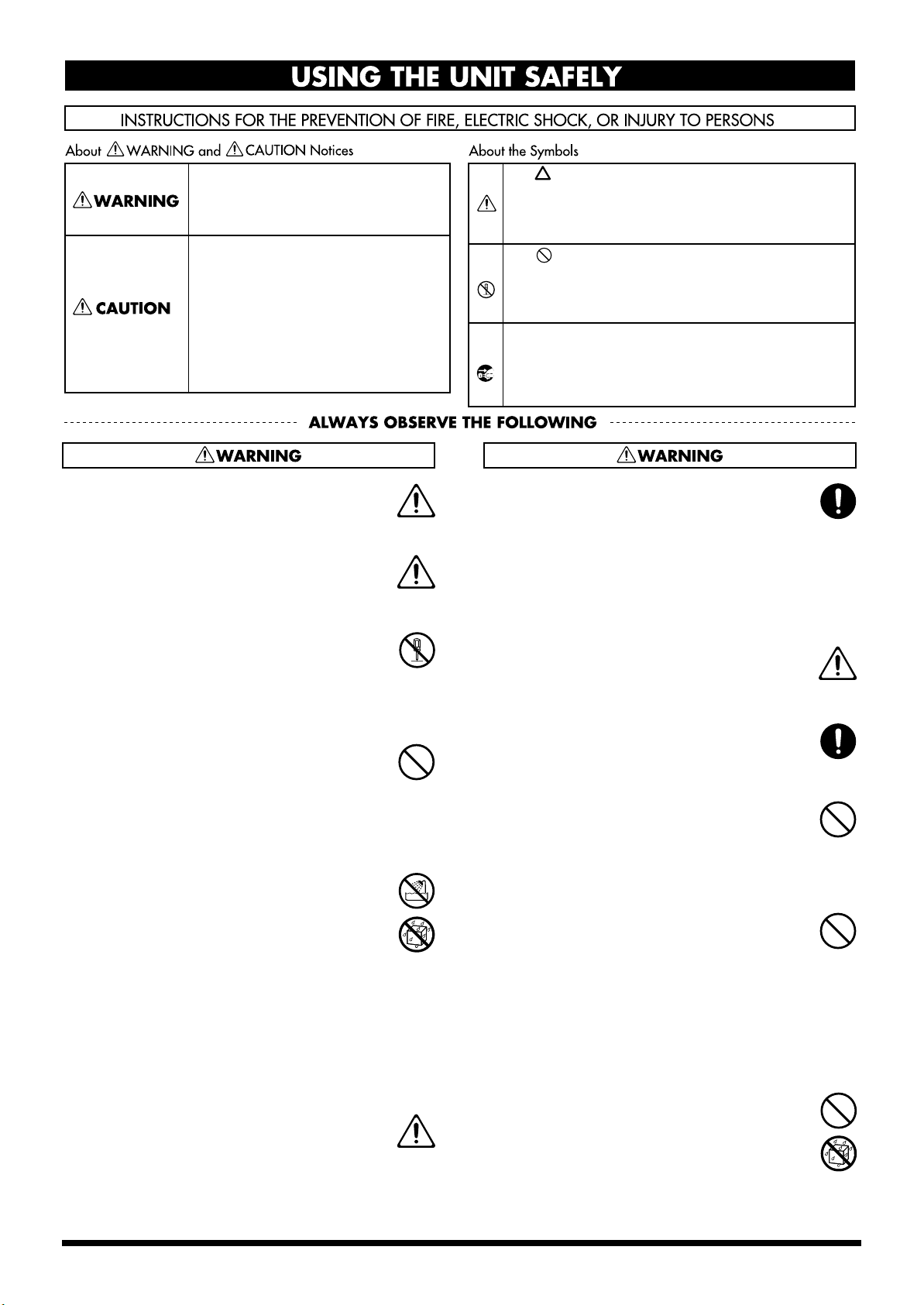
The symbol alerts the user to important instructions
or warnings.The specific meaning of the symbol is
determined by the design contained within the
triangle. In the case of the symbol at left, it is used for
general cautions, warnings, or alerts to danger.
The symbol alerts the user to items that must never
be carried out (are forbidden). The specific thing that
must not be done is indicated by the design contained
within the circle. In the case of the symbol at left, it
means that the unit must never be disassembled.
The ● symbol alerts the user to things that must be
carried out. The specific thing that must be done is
indicated by the design contained within the circle. In
the case of the symbol at left, it means that the powercord plug must be unplugged from the outlet.
006
• When using the unit with a rack or stand recommended by Roland, the rack or stand must be
carefully placed so it is level and sure to remain
stable. If not using a rack or stand, you still need
to make sure that any location you choose for
placing the unit provides a level surface that will
properly support the unit, and keep it from
wobbling.
..........................................................................................................
008a
• The unit should be connected to a power supply
only of the type described in the operating
instructions, or as marked on the rear side of unit.
..........................................................................................................
008e
• Use only the attached power-supply cord. Also,
the supplied power cord must not be used with
any other device.
..........................................................................................................
009
• Do not excessively twist or bend the power cord,
nor place heavy objects on it. Doing so can
damage the cord, producing severed elements
and short circuits. Damaged cords are fire and
shock hazards!
..........................................................................................................
010
• This unit, either alone or in combination with an
amplifier and headphones or speakers, may be
capable of producing sound levels that could
cause permanent hearing loss. Do not operate for
a long period of time at a high volume level, or at
a level that is uncomfortable. If you experience
any hearing loss or ringing in the ears, you should
immediately stop using the unit, and consult an
audiologist.
..........................................................................................................
011
• Do not allow any objects (e.g., flammable
material, coins, pins); or liquids of any kind
(water, soft drinks, etc.) to penetrate the unit.
..........................................................................................................
..........................................................................................................
3
Page 4
012a
• Immediately turn the power off, remove the
power cord from the outlet, and request servicing
by your retailer, the nearest Roland Service
Center, or an authorized Roland distributor, as
listed on the “Information” page when:
• The power-supply cord, or the plug has been
damaged; or
• If smoke or unusual odor occurs
• Objects have fallen into, or liquid has been
spilled onto the unit; or
• The unit has been exposed to rain (or otherwise
has become wet); or
• The unit does not appear to operate normally
or exhibits a marked change in performance.
..........................................................................................................
013
• In households with small children, an adult
should provide supervision until the child is
capable of following all the rules essential for the
safe operation of the unit.
..........................................................................................................
014
• Protect the unit from strong impact.
(Do not drop it!)
..........................................................................................................
015
• Do not force the unit’s power-supply cord to
share an outlet with an unreasonable number of
other devices. Be especially careful when using
extension cords—the total power used by all
devices you have connected to the extension
cord’s outlet must never exceed the power rating
(watts/amperes) for the extension cord. Excessive
loads can cause the insulation on the cord to heat
up and eventually melt through.
..........................................................................................................
016
• Before using the unit in a foreign country, consult
with your retailer, the nearest Roland Service
Center, or an authorized Roland distributor, as
listed on the “Information” page.
..........................................................................................................
022a
• Always turn the unit off and unplug the power
cord before attempting installation of the circuit
board (SRX Series; p. 15 ).
..........................................................................................................
023
• DO NOT play a CD-ROM disc on a conventional
audio CD player. The resulting sound may be of a
level that could cause permanent hearing loss.
Damage to speakers or other system components
may result.
..........................................................................................................
026
• Do not put anything that contains water (e.g.,
flower vases) on this unit. Also, avoid the use of
insecticides, perfumes, alcohol, nail polish, spray
cans, etc., near the unit. Swiftly wipe away any
liquid that spills on the unit using a dry, soft
cloth.
..........................................................................................................
101a
• The unit should be located so that its location or
position does not interfere with its proper ventilation.
..........................................................................................................
101c
• This (RD-700SX) for use only with Roland stand
KS-17. Use with other stands (or carts) is capable
of resulting in instability causing possible injury.
..........................................................................................................
102b
• Always grasp only the plug on the power-supply
cord when plugging into, or unplugging from, an
outlet or this unit.
..........................................................................................................
103a
• At regular intervals, you should unplug the
power plug and clean it by using a dry cloth to
wipe all dust and other accumulations away from
its prongs. Also, disconnect the power plug from
the power outlet whenever the unit is to remain
unused for an extended period of time. Any
accumulation of dust between the power plug
and the power outlet can result in poor insulation
and lead to fire.
..........................................................................................................
104
• Try to prevent cords and cables from becoming
entangled. Also, all cords and cables should be
placed so they are out of the reach of children.
..........................................................................................................
106
• Never climb on top of, nor place heavy objects on
the unit.
..........................................................................................................
107b
• Never handle the power cord or its plugs with
wet hands when plugging into, or unplugging
from, an outlet or this unit.
..........................................................................................................
108a
• Before moving the unit, disconnect the power
plug from the outlet, and pull out all cords from
external devices.
..........................................................................................................
109a
• Before cleaning the unit, turn off the power and
unplug the power cord from the outlet (p. 23 ).
..........................................................................................................
110a
• Whenever you suspect the possibility of lightning
in your area, pull the plug on the power cord out
of the outlet.
..........................................................................................................
115a
• Install only the specified circuit board(s) (SRX
Series). Remove only the specified screws (p. 15 ).
..........................................................................................................
118a
• Should you remove the screws fastening the
board slot cover, keep them in a safe place out of
children’s reach, so there is no chance of them
being swallowed accidentally.
..........................................................................................................
4
Page 5

IMPORTANT NOTES
291b
In addition to the items listed under “IMPORTANT SAFETY INSTRUCTIONS” and “USING THE UNIT SAFELY” on pages 3
and 4, please read and observe the following:
Power Supply
301
• Do not connect this unit to same electrical outlet that is being
used by an electrical appliance that is controlled by an inverter
(such as a refrigerator, washing machine, microwave oven, or air
conditioner), or that contains a motor. Depending on the way in
which the electrical appliance is used, power supply noise may
cause this unit to malfunction or may produce audible noise. If it
is not practical to use a separate electrical outlet, connect a power
supply noise filter between this unit and the electrical outlet.
307
• Before connecting this unit to other devices, turn off the power to
all units. This will help prevent malfunctions and/or damage to
speakers or other devices.
308
• Although the LCD and LEDs are switched off when the POWER
switch is switched off, this does not mean that the unit has been
completely disconnected from the source of power. If you need
to turn off the power completely, first turn off the POWER
switch, then unplug the power cord from the power outlet. For
this reason, the outlet into which you choose to connect the
power cord’s plug should be one that is within easy reach and
readily accessible.
Placement
351
• Using the unit near power amplifiers (or other equipment
containing large power transformers) may induce hum. To
alleviate the problem, change the orientation of this unit; or
move it farther away from the source of interference.
352a
• This device may interfere with radio and television reception. Do
not use this device in the vicinity of such receivers.
352b
• Noise may be produced if wireless communications devices,
such as cell phones, are operated in the vicinity of this unit. Such
noise could occur when receiving or initiating a call, or while
conversing. Should you experience such problems, you should
relocate such wireless devices so they are at a greater distance
from this unit, or switch them off.
354a
• Do not expose the unit to direct sunlight, place it near devices
that radiate heat, leave it inside an enclosed vehicle, or otherwise
subject it to temperature extremes. Excessive heat can deform or
discolor the unit.
355b
• When moved from one location to another where the temperature and/or humidity is very different, water droplets (condensation) may form inside the unit. Damage or malfunction may
result if you attempt to use the unit in this condition. Therefore,
before using the unit, you must allow it to stand for several
hours, until the condensation has completely evaporated.
358
• Do not allow objects to remain on top of the keyboard. This can
be the cause of malfunction, such as keys ceasing to produce
sound.
Maintenance
401a
• For everyday cleaning wipe the unit with a soft, dry cloth or one
that has been slightly dampened with water. To remove
stubborn dirt, use a cloth impregnated with a mild, non-abrasive
detergent. Afterwards, be sure to wipe the unit thoroughly with
a soft, dry cloth.
402
• Never use benzine, thinners, alcohol or solvents of any kind, to
avoid the possibility of discoloration and/or deformation.
Repairs and Data
452
• Please be aware that all data contained in the unit’s memory may
be lost when the unit is sent for repairs. Important data should
always be backed up in another MIDI device (e.g., a sequencer),
or written down on paper (when possible). During repairs, due
care is taken to avoid the loss of data. However, in certain cases
(such as when circuitry related to memory itself is out of order),
we regret that it may not be possible to restore the data, and
Roland assumes no liability concerning such loss of data.
Additional Precautions
551
• Please be aware that the contents of memory can be irretrievably
lost as a result of a malfunction, or the improper operation of the
unit. To protect yourself against the risk of loosing important
data, we recommend that you periodically save a backup copy of
important data you have stored in the unit’s memory in another
MIDI device (e.g., a sequencer).
552
• Unfortunately, it may be impossible to restore the contents of
data that was stored in another MIDI device (e.g., a sequencer)
once it has been lost. Roland Corporation assumes no liability
concerning such loss of data.
553
• Use a reasonable amount of care when using the unit’s buttons,
sliders, or other controls; and when using its jacks and
connectors. Rough handling can lead to malfunctions.
554
• Never strike or apply strong pressure to the display.
556
• When connecting / disconnecting all cables, grasp the connector
itself—never pull on the cable. This way you will avoid causing
shorts, or damage to the cable’s internal elements.
557
• A small amount of heat will radiate from the unit during normal
operation.
558a
• To avoid disturbing your neighbors, try to keep the unit’s
volume at reasonable levels. You may prefer to use headphones,
so you do not need to be concerned about those around you
(especially when it is late at night).
559a
• When you need to transport the unit, package it in the box
(including padding) that it came in, if possible. Otherwise,
you will need to use equivalent packaging materials.
561
• Use only the specified expression pedal (EV-5/7; sold
separately). By connecting any other expression pedals, you risk
causing malfunction and/or damage to the unit.
Handling CD-ROMs
801
• Avoid touching or scratching the shiny underside (encoded
surface) of the disc. Damaged or dirty CD-ROM discs may not be
read properly. Keep your discs clean using a commercially
available CD cleaner.
5
Page 6

Main Features
Progressive Hammer Action
The RD-700SX incorporates Roland’s “progressive hammer action
keyboard,” which realistically reproduces the comfortable, natural
touch of the grand piano. While offering excellent responsiveness
and quiet action, this keyboard also reproduces the subtle changes in
touch as you move from the lower to the higher registers.
Additionally, the progressive hammer action keyboard features an
environmentally friendly design, with absolutely no lead used in the
hammers.
New Piano Tones
The instrument features newly developed, authentic piano tones
with wide dynamic range and rich expression. Great for any musical
genre or scene, whether it be performing with a band or playing a
solo ballad, the RD-700SX is the perfect stage piano.
Additionally, The instrument features an 88-note multisampled
piano painstakingly recorded by professional engineers. It boasts not
only tonal quality but also a high level of presence, making it closer
than ever to the “real thing.”
It is also furnished with a wealth of electronic piano, organ, string,
synth pad, and other Tones that allow you to use the instrument as a
stage piano. Once you try it onstage, you'll come to fully understand
its capabilities.
Exclusive Piano Functions
The “Piano Edit” function allows you to program subtle changes for
the piano and electric piano tones (p. 73).
A Full 128 Voices
The RD-700SX features 128-voice polyphony, with all sounds
available in every performance mode. Enjoy natural performances
even when layering multiple sounds.
Simple Push-Button Operation
You can access Split, Effects and carry out other main operations
simply by pressing a single button (p. 12).
Furthermore, pressing the ONE TOUCH [PIANO] button lets you
immediately switch to the settings most suited for piano
performances, regardless of the mode or settings currently in effect
(p. 32).
High-Quality Effects
In addition to two multi-effects systems, you can also use the reverb
and chorus individually. The instrument also realistically
reproduces the tonal changes of an acoustic grand piano, including
the change in resonance created by pressing the damper pedal (p. 75)
and the degree of openness of the grand piano’s lid (p. 74).
Moreover, the Sound Control function (p. 44) and digital equalizer
(p. 45) enable a wide range of tonal adjustments.
Equipped With Organ Tone Wheel
Sound Generator
For organ Tones, the RD-700SX comes equipped with an organ Tone
wheel sound generator used in the Roland Combo Organ. This
sound generator lets you recreate organ sounds, changing the level
of each footage (p. 54).
Rhythm and Arpeggiator Functions
You can play back Rhythm patterns and perform arpeggios with the
press of a single button.
Enjoy a variety of performance techniques, with backing using
realistic drum sounds for a real session feel, arpeggios and cutting
you get just by playing the chords, and more (p. 46,p. 48).
Fast MIDI Control
You can also control various functions, such as adjusting volume
levels and selecting Tones, simply and easily from an external MIDI
device. This provides fast and intuitive control when using the
keyboard on stage (p. 60).
Interface for Full Connectivity
The RD-700SX comes equipped with a USB port for connecting to
computers. You can use this to perform with MIDI data received
from the computer and to save the RD-700SX’s setup files.
Additionally, two separate MIDI OUT ports allow you to control two
different MIDI sound modules simultaneously.
On top of all this, the RD-700SX XLR connectors provide balanced
output to connected audio gear, enabling you to supply stable audio
output.
Expandability
You can install up to two Wave Expansion Boards, a favorite for use
with Roland’s SRX Series.
Starting with the “SRX-02 Concert Grand” Tone, you can enjoy
performing with the most up-to-date Tones available as they are
continually released (p. 15).
Sophisticated Design
With its black body, the RD-700SX offers the perfect look and
presence on stage. The panel’s refined design enhances operability,
while rear cable connections are a cinch.
In addition, the cover to the wave expansion board is designed so it
won’t easily fall off even if the screws are removed.
SMF Play Function
The RD-700SX is compatible with both General MIDI and General
MIDI 2 standards. Additionally, you can transmit SMF music files to
the RD-700SX from the USB port and play back the data. This allows
you to perform while playing back SMF music files without the use
of an external sequencer.
Convention Used in This Manual
• Words enclosed in square brackets [ ] indicate panel buttons.
Example: [SPLIT] indicates the SPLIT button.
• (p. **) indicates a reference page
• The explanations in this manual include illustrations that depict
what should typically be shown by the display. Note, however,
that your unit may incorporate a newer, enhanced version of
the system (e.g., includes newer sounds), so what you actually
see in the display may not always match what appears in the
manual.
6
Page 7

Contents
USING THE UNIT SAFELY............................................................................................................................... 3
IMPORTANT NOTES......................................................................................................................................... 5
Main Features..........................................................................................6
Panel Descriptions................................................................................12
Front Panel .........................................................................................................................................................12
Rear Panel...........................................................................................................................................................14
Getting Ready........................................................................................15
Installing the Wave Expansion Board ............................................................................................................ 15
Cautions When Installing an Wave Expansion Board..................................................................... 15
Installing SRX Series Boards................................................................................................................ 16
Checking the Installed Wave Expansion Boards.............................................................................. 17
Installation de la carte d’extension Wave(French language for Canadian Safety Standard)................. 18
Precautions lors de l’installation de la carte d’extension Wave .....................................................18
Installer les cartes de serie SRX ...........................................................................................................19
Verification des cartes d’extension audio apres installation........................................................... 20
Connecting the RD-700SX to External Equipment....................................................................................... 21
Connecting Pedals................................................................................................................................. 22
Turning the Power On and Off .......................................................................................................................23
Turning On the Power.......................................................................................................................... 23
Turning Off the Power.......................................................................................................................... 24
Adjusting the Volume....................................................................................................................................... 24
Restoring the Factory Settings (Factory Reset).............................................................................................. 25
Adjusting the Display Contrast (LCD Contrast) .......................................................................................... 26
Tuning to Other Instruments’ Pitches (Master Tune).................................................................................. 27
Overview of the RD-700SX ...................................................................28
Basic Organization of the RD-700SX .............................................................................................................. 28
Units of Sound ...................................................................................................................................................28
Basic Operation.................................................................................................................................................. 28
Main Screens ..........................................................................................................................................28
Special Indications................................................................................................................................. 29
About the Function Buttons................................................................................................................. 29
About the CURSOR Buttons................................................................................................................ 30
Changing the Settings Values..............................................................................................................30
Listening to the Demo (DEMO PLAY) .................................................31
Performing with the Keyboard.............................................................32
Piano Performances (ONE TOUCH).............................................................................................................. 32
Performing with a Variety of Tones ...............................................................................................................33
Specifying the Tone Number to Select a Tone ([NUM LOCK])...................................................... 34
Selecting Wave Expansion Board Tones............................................................................................35
Playing Multiple Tones with the Keyboard ..................................................................................................37
Performing with Layered Tones ......................................................................................................... 37
Playing Different Tones in Two Different Sections of the Keyboard ([SPLIT]) ...........................38
Changing the Tone for a Zone.............................................................................................................40
Adjust the Volume Level for Individual Zones (ZONE SWITCH/ZONE LEVEL Slider)..................... 41
Transposing the Key of the Keyboard ([TRANSPOSE]).............................................................................. 42
Adding Reverberation to the Sound ([REVERB])......................................................................................... 43
Adding Breadth to the Sound ([CHORUS/DELAY]).................................................................................. 43
Changing the Sound’s Pitch in Real Time (Bender/Modulation Lever)................................................... 44
Adding Liveliness to the Sound ([SOUND CONTROL])............................................................................ 44
Adjusting the Level of the Sound’s Low, Mid, and High-Frequency Ranges ([EQUALIZER])............ 45
7
Page 8

Contents
Using the Convenient Functions in Performances............................46
Playing Arpeggios ([ARPEGGIO]) .................................................................................................................46
Changing the Arpeggio Style .............................................................................................................. 47
Changing Arpeggio Tempos................................................................................................................ 47
Playing Rhythm ([RHYTHM/SONG]) ..........................................................................................................48
Changing the Rhythm Pattern............................................................................................................. 49
Changing Rhythm Tempos.................................................................................................................. 49
Playing the Songs ([RHYTHM/SONG])........................................................................................................ 50
Selecting the Song.................................................................................................................................. 51
Changing Song Tempos ....................................................................................................................... 51
Applying Effects to the Sound (Multi-Effects).............................................................................................. 52
Simulating the Creation of Organ Tones (Tone Wheel Mode)................................................................... 53
Changing the Undulation of the Organ Tone (Rotary Effect)......................................................... 54
Changing the ZONE LEVEL Slider Feet Assignments (Harmonic Bar) .......................................54
Disabling the Button (Panel Lock) .................................................................................................................. 55
Selecting Stored Settings ([SETUP])................................................................................................................ 56
Registering the Setups You Like (Favorite Setups) .......................................................................... 57
Storing Settings to Setups ([WRITE]) .............................................................................................................58
Using the RD-700SX As a Master Keyboard.......................................60
What’s MIDI?..................................................................................................................................................... 60
About MIDI Connectors....................................................................................................................... 60
Connecting to External MIDI Sound Generators.............................................................................. 60
Selecting the MIDI Connector to Use for Output (MIDI OUT Port).......................................................... 61
MIDI Send Channel Settings............................................................................................................................ 62
Selecting Sounds on an External MIDI Device.............................................................................................. 63
Adjusting the Volume of Each Zone (EXTERNAL Zone)........................................................................... 64
Detailed Settings for Transmitted Parts (EXTERNAL).......................................................................65
How to Make Settings ..................................................................................................................65
Adjusting the Volume and Pan (Volume/Pan)........................................................................ 65
Setting the Amount of Reverb and Chorus (Reverb/Chorus) ...............................................65
Playing Sound Monophonically (Mono/Poly).........................................................................66
Setting the Transposition for Each Individual Zone (Transpose)..........................................66
Setting the Key Range (Key Range Lower/Upper) .................................................................66
Changing the Range That Plays in Response to the Velocity
(Velocity Range Lower/Upper)..................................................................................................66
Changing Tone Elements (ATK/DCY/REL/COF/RES)........................................................ 66
Smoothly Changing the Pitch (Portamento) .............................................................................67
Setting the Change in Volume According to the Force Used to Play the Keyboard
(Velocity Sensitivity/Max) ..........................................................................................................67
Changing the Pitch (Coarse Tune/Fine Tune).......................................................................... 67
Setting the Range for the Change in Pitch with the Bender (Bend Range)........................... 67
Setting the Amount of Modulation Applied (Modulation Depth) ........................................ 67
Turning Each Controller On and Off .........................................................................................67
Transmitting the Control Change (USER CC/USER CC Value) ...........................................67
Making Detailed Settings for Tones ....................................................68
Making Zone Settings (Zone Info).................................................................................................................. 68
How to Make Settings........................................................................................................................... 68
Selecting the Tone.................................................................................................................................. 68
Setting the Volume and Pan (Volume/Pan)...................................................................................... 68
Setting the Zone to Which Multi-effects Are Applied (MFX1/MFX2 Source)............................. 68
Setting the Transposition for Each Individual Zone (Transpose).................................................. 69
Setting the Key Range for Each Zone (Key Range) .......................................................................... 69
Setting the Change in Volume According to the Force Used to Play the Keyboard
(Velocity Range/Sens/Max)................................................................................................................ 69
Assigning Internal Parts to INTERNAL Zone (Part Assign).......................................................... 69
Turning the Controllers in Each Zone On and Off........................................................................... 70
8
Page 9

Contents
Making Tone Settings (Tone Info)................................................................................................................... 70
How to Make Settings........................................................................................................................... 70
Selecting the Part and the Tone to Be Set (Part, Tone)..................................................................... 71
Setting the Reverb/Chorus Depth (Reverb/Chorus Amount) ......................................................71
Changing the Effect Applied to the Tone (MFX Type).................................................................... 71
Playing Sound Monophonically (Mono/Poly) ................................................................................. 71
Changing the Pitch (Coarse Tune/Fine Tune).................................................................................. 71
Creating Smooth Pitch Changes (Portamento Switch/Time)......................................................... 71
Changing Tone Elements (Attack Time/Release Time/Cutoff/Resonance/Decay Time)........ 72
Changing the Bend Range (Bend Range)........................................................................................... 72
Making Detailed Settings for the ONE TOUCH Tones .......................73
Making Detailed Settings for the Piano Tones (Piano Edit)........................................................................ 73
Making the settings............................................................................................................................... 73
Selecting the Piano Sound.................................................................................................................... 73
Changing the Width of the Sound (Stereo Width) ........................................................................... 73
Changing the Sound’s Nuance (Nuance)........................................................................................... 73
Changing the Sense of Space Surrounding the Sound (Ambience)............................................... 73
Changing the Amount of Reverb Effect (Reverb Level).................................................................. 73
Opening/Closing the Piano Lid (Lid)................................................................................................ 74
Changing the Characteristics of the Mic (Mic Type/Distance)...................................................... 74
Adjusting the Resonant Sounds When the Keys are Pressed (String Resonance)....................... 74
Making the Midrange Equalizer Settings (EQ SW/EQ Gain/EQ Frequency/EQ Q)................. 74
Changing the Key Touch (Key Touch)............................................................................................... 74
Making Fine Adjustments to the Keyboard Touch (Key Touch Offset)........................................ 75
Setting a Constant Volume Level in Response to the Playing Force (Velocity)........................... 75
Changing the Timing of Sounds in Response to the Velocity (Velocity Delay Sens).................. 75
Changing the Touch Sensitivity According to the Key Range (Velocity Keyfollow Sens)......... 75
Finely Adjusting the Tuning (Micro Tune)........................................................................................75
Adjusting Resonance when the Damper Pedal is Depressed (Sympathetic Resonance)............ 75
Changing Sound Characteristics (Tone Modify) .............................................................................. 76
Restore the settings to initial conditions (Initialize).........................................................................76
Making Detailed Settings for the E.Piano Tones (E.Piano Edit)................................................................. 76
Making the settings............................................................................................................................... 76
Selecting the E.Piano Sound................................................................................................................. 77
Selecting the Amp Type(AMP Type).................................................................................................. 77
Applying Effects to the Sound (Effect Type/Depth/Rate)............................................................. 77
Making the Midrange Equalizer Settings (EQ-SW/EQ Gain/EQ Frequency/EQ Q) ................ 77
Changing Sound Characteristics (Tone Modify) .............................................................................. 77
Detailed Settings for Each Function ([EDIT]) .....................................78
Parameters That Can Be Set............................................................................................................................. 78
Setting Parameters................................................................................................................................. 79
Making System Settings (System)................................................................................................................... 79
How to Make Settings........................................................................................................................... 79
Adjusting the Volume (Master Volume)............................................................................................80
Preventing Equalizer Settings from Being Switched (EQ Mode)...................................................80
Preventing Pedal Settings from Being Switched (Pedal Mode)...................................................... 80
Retaining the Current Tone Even When Tones Are Switched (Tone Remain) ............................ 81
Changing the Clock (Timing) Source (Clock Source) ...................................................................... 81
Transmitting Synchronization Messages (Clock Out) ..................................................................... 81
Using Program Change Messages to Switch Setups (SETUP Control Channel) .........................81
Setting the Device ID Number (Device ID) ....................................................................................... 81
Switching the Pedal’s Polarity (Pedal/FC1/FC2 Polarity) ............................................................. 81
Selecting the Display Appearance (Display Mode).......................................................................... 82
Selecting the Number of Parts (Part Mode).......................................................................................82
Setting the Tuning Method (Temperament/Key) ............................................................................ 82
Precise Modification of Chord Sonorities (Stretch Tune)................................................................ 82
Switching Between Reception of GM/GM2 System On and GS Reset......................................... 82
Setting the Keyboard Touch (Key Touch)...................................................................................................... 83
9
Page 10

Contents
How to Make Settings........................................................................................................................... 83
Changing the Key Touch (Key Touch)............................................................................................... 83
Making Fine Adjustments to the Keyboard Touch (Key Touch Offset)........................................ 83
Setting a Constant Volume Level in Response to the Playing Force (Velocity)........................... 84
Changing the Timing of Sounds in Response to the Velocity (Velocity Delay Sens).................. 84
Changing the Touch Sensitivity According to the Key Range (Velocity Keyfollow Sens)......... 84
Pedal and MULTI EFFECTS [CONTROL] Knob Settings (Control).......................................................... 84
How to Make Settings........................................................................................................................... 84
Assigning Functions to Pedals (FC1/FC2 Pedal Assign)................................................................ 85
Changing the MULTI EFFECTS [CONTROL] Knob Settings (Control Knob Assign)................ 85
Changing the Slider Settings (Slider Assign) ....................................................................................85
Setting the Multi-Effects, Reverb, and Chorus Effects (Effects) .................................................................86
How to Make Settings........................................................................................................................... 86
Making Multi-Effects Settings ............................................................................................................. 86
Making Reverb Settings........................................................................................................................ 87
Setting Chorus and Delay ....................................................................................................................88
Making the Sound Control Settings (Sound Control).................................................................................. 88
How to Make Settings........................................................................................................................... 88
Selecting the Type of Compressor (Sound Control Type)............................................................... 89
Detailed Settings of Compressor......................................................................................................... 89
Managing Setup Files (File Utility/USB).......................................................................................................89
Saving Setup Files to the Memory (Save SETUP File) .....................................................................89
Calling Up Setup Files from Memory (Load SETUP File)............................................................... 90
Deleting Files from Memory (File Delete) .........................................................................................91
Setting MIDI Receive Parts (Part Parameter)................................................................................................ 91
How to Make Settings........................................................................................................................... 91
Selecting the Part to Be Set (Part/Tone)............................................................................................. 92
Setting the Receive Channel (Receive Channel) ...............................................................................92
Setting the Volume and Pan (Volume/Pan)...................................................................................... 92
Setting the Required Polyphony (Voice Reserve)............................................................................. 92
Preventing Parts from Being Played (Part Switch)........................................................................... 92
Making the Effect ON/OFF Settings (MFX Switch)......................................................................... 92
Setting Reception and Blocking of MIDI Messages from External MIDI Controllers................. 92
Making the Rhythm and Arpeggio Settings (Rhythm/Arpeggio) ............................................................93
How to Make Settings........................................................................................................................... 93
Making the rhythm Settings ................................................................................................................93
Making Arpeggio Settings ...................................................................................................................95
About V-LINK ...................................................................................................................................................97
Connection Examples ...........................................................................................................................97
Turning the V-Link ON/OFF.............................................................................................................. 97
V-Link Settings....................................................................................................................................... 97
Detailed Settings of V-Link.................................................................................................................. 98
Other Functions (Utility).................................................................................................................................. 98
Transferring the RD-700SX’s Settings to an External MIDI Device (Bulk Dump)....................... 98
Restoring the settings to the factory condition (Factory Reset).................................................... 100
Connecting External MIDI Devices....................................................101
Recording RD-700SX Performances to an External MIDI Sequencer...................................................... 101
Connecting to an External Sequencer............................................................................................... 101
Settings for Recording (Rec Setting) ................................................................................................. 101
Recording the Performance................................................................................................................ 102
Exiting Rec Mode................................................................................................................................. 102
About the Local Switch....................................................................................................................... 102
Playing the RD-700SX’s Internal Sound Generator from an External MIDI Device .............................103
Making Connections ........................................................................................................................... 103
Setting the Channels ........................................................................................................................... 103
Selecting RD-700SX Sounds from an External MIDI Device......................................................... 103
Switching Setups .................................................................................................................................103
Switching Tones................................................................................................................................... 103
10
Page 11

Contents
Connecting to Your Computer via USB (USB Mode).......................104
About USB Functions...................................................................................................................................... 104
Switching Between Storage Mode and MIDI Mode................................................................................... 104
Exchanging Files with Computers (Storage Mode).................................................................................... 105
Connections.......................................................................................................................................... 105
Cautions Regarding Folders and Files .............................................................................................105
Exchanging Files..................................................................................................................................105
Exiting Storage Mode.......................................................................................................................... 105
Exchanging MIDI Messages with Your Computer (MIDI Mode)............................................................ 106
Switching USB Drivers ................................................................................................................................... 106
Appendices..........................................................................................108
Troubleshooting............................................................................................................................................... 108
Error Messages/Other Messages.................................................................................................................. 111
Error Messages..................................................................................................................................... 111
Other Messages.................................................................................................................................... 111
Effect/Parameter List...................................................................................................................................... 112
Multi-Effects Parameter...................................................................................................................... 112
Chorus Parameter................................................................................................................................ 144
Reverb Parameter ................................................................................................................................ 145
Tone List ...........................................................................................................................................................146
Rhythm Set List................................................................................................................................................ 149
Arpeggio Style List.......................................................................................................................................... 152
Rhythm Pattern List........................................................................................................................................ 153
Setup List .......................................................................................................................................................... 154
Shortcut List .....................................................................................................................................................155
MIDI Implementation.....................................................................................................................................156
Main Specifications .........................................................................................................................................172
Index.................................................................................................................................................................. 173
Purpose-Oriented Index................................................................................................................................. 178
Volume Setting..................................................................................................................................... 178
Key Touch and Velocity .....................................................................................................................178
Equalizer............................................................................................................................................... 178
Pitch and Tuning .................................................................................................................................178
Effects (Reverb, Chorus, Multi-Effects)............................................................................................ 178
Control ..................................................................................................................................................178
Key Range............................................................................................................................................. 178
11
Page 12
Panel Descriptions
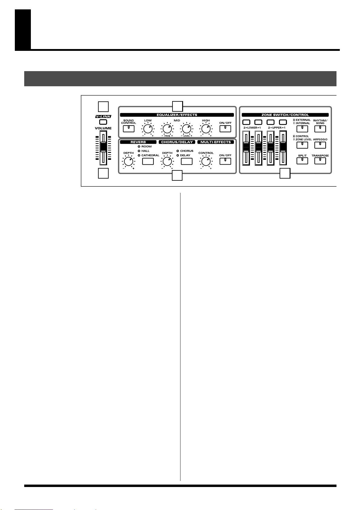
Front Panel
fig.buttons
1
1. [V-LINK]
Switching this on lets you control external V-LINK compatible video
equipment connected to the RD-700SX (p. 97).
2. VOLUME Slider
Adjusts the overall volume that is output from the rear panel
OUTPUT jacks and PHONES jack (p. 24).
3. EQUALIZER/EFFECTS
[SOUND CONTROL]
Switching this on reduces inconsistencies in the volume and
produces a more stable, coherent sound (p. 44).
3
4
[CHORUS/DELAY]
Changes the chorus type (p. 43).
MULTI-EFFECTS [CONTROL] knob
Adjusts the way that effects are applied (p. 52).
MULTI-EFFECTS [ON/OFF]
Switches the multi-effects on/off (p. 52).
5. ZONE SWITCH/CONTROL
ZONE SWITCH
Turns each part’s sound on and off (p. 41).
52
[LOW] knob
Adjusts the sound’s low-frequency range (p. 45).
[MID FREQ] knob
Adjusts the midrange frequencies (p. 45).
[MID LEVEL] knob
Adjusts the sound’s midrange-frequency range (p. 45).
[HIGH] knob
Adjusts the sound’s high-frequency range (p. 45).
[ON/OFF]
Turns the equalizer on/off (p. 45).
4. REVERB, CHORUS/DELAY, MULTI-EFFECTS
REVERB [DEPTH] knob
Adjusts the amount of reverb (p. 43).
[REVERB]
Changes the reverb type (p. 43).
CHORUS/DELAY [DEPTH] knob
Adjusts the amount of chorus (p. 43).
ZONE LEVEL slider
Adjusts the volume level for each part (p. 41).
When [EXTERNAL/INTERNAL] is on, this controls each part for
the external MIDI sound generator (p. 64).
In addition, when [CONTROL/ZONE LEVEL] is on, the tone is
changed in real time in response to the assigned parameter and
function.
[EXTERNAL/INTERNAL]
Puts the RD-700SX in control of the external MIDI sound generator
(p. 60).
[RHYTHM/SONG]
Switches RHTYHM and SONG on/off (p. 48, p. 50).
[CONTROL/ZONE LEVEL]
This determines the function of the ZONE LEVEL sliders (p. 85).
[ARPEGGIO]
Switches Arpeggiator on/off (p. 46).
[SPLIT]
Puts the keyboard in “Split mode,” wherein you can use more than
one tone by having different tones play in different parts of the
keyboard (p. 38).
12
Page 13
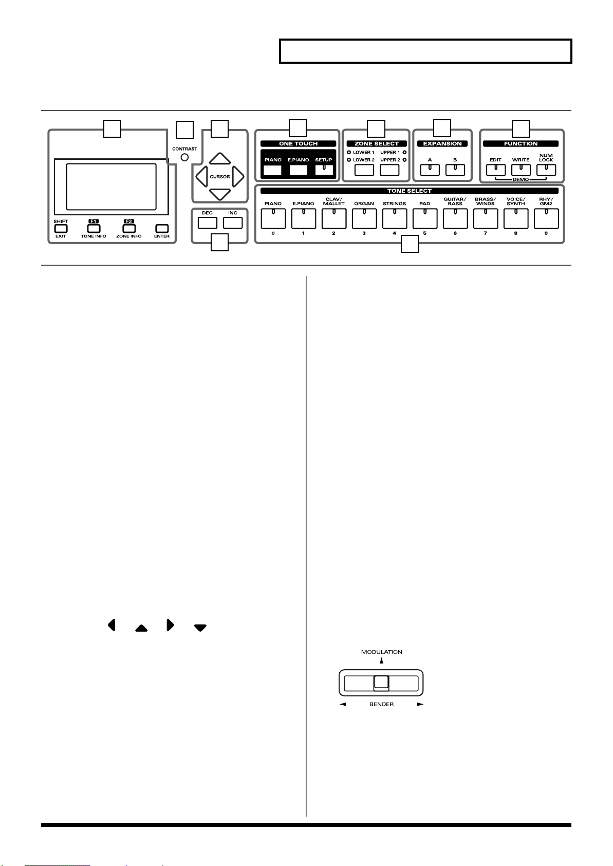
fig.buttons
Panel Descriptions
6
7
8
9
[TRANSPOSE]
Sets the range of the keyboard to transposed (p. 42).
6. DISPLAY
This shows the Tone names and the values of various settings, etc.
[SHIFT/EXIT]
Pressed to return to a previous screen or to cancel a procedure that is
in progress.
Additionally, you can easily call up Edit screens for related
parameters for the following functions by holding down this button
while pressing buttons, turning knobs, or operating other controllers
(p. 155).
[F1/TONE INFO]
This allows you to change the tone settings (p. 70).
You can also use this to assign functions in some screens.
[F2/ZONE INFO]
This allows you to change the zone settings (p. 68).
You can also use this to assign functions in some screens.
[ENTER]
This is used to finalize a value or execute an operation.
7. CONTRAST knob
Adjusts the display’s contrast (p. 26).
8. CURSOR [ ], [ ], [ ], [ ]
Press these to switch pages and to move the cursor.
10
11
12
13
14
[SETUP]
Calls up the stored settings (Setup) (p. 56).
11. ZONE SELECT buttons
Selects the zone for which the tone is to be selected (p. 40).
12. EXPANSION [A], [B]
This selects a sound from a wave expansion board, sold separately
(p. 35).
13. FUNCTION
[EDIT]
Press this button when you wish to adjust various settings (p. 78).
[WRITE]
Stores the current settings to “Setup” (p. 58).
[NUM LOCK]
You can input numerical values with the TONE SELECT buttons
when this button is lit (p. 34).
In addition, you can listen to the demo songs by simultaneously
pressing this button and [EDIT] (DEMO PLAY) (p. 31).
14. TONE SELECT buttons
Pressed to select tones (p. 33).
You can also input numerical values with these buttons when the
[NUM LOCK] button is on. [NUM LOCK] turns on automatically in
the Edit and other screens, enabling input of numerical values with
the buttons.
fig.Bender
9. [DEC], [INC]
This is used to modify values.
If you keep on holding down one button while pressing the other,
the value change accelerates.
10. ONE TOUCH
[PIANO]
Selects the optimum settings for piano performances (p. 32).
[E.PIANO]
Selects the optimum settings for E.piano performances (p. 32).
Pitch Bend/Modulation Lever
This allows you to control pitch bend or apply vibrato (p. 44).
13
Page 14
Panel Descriptions
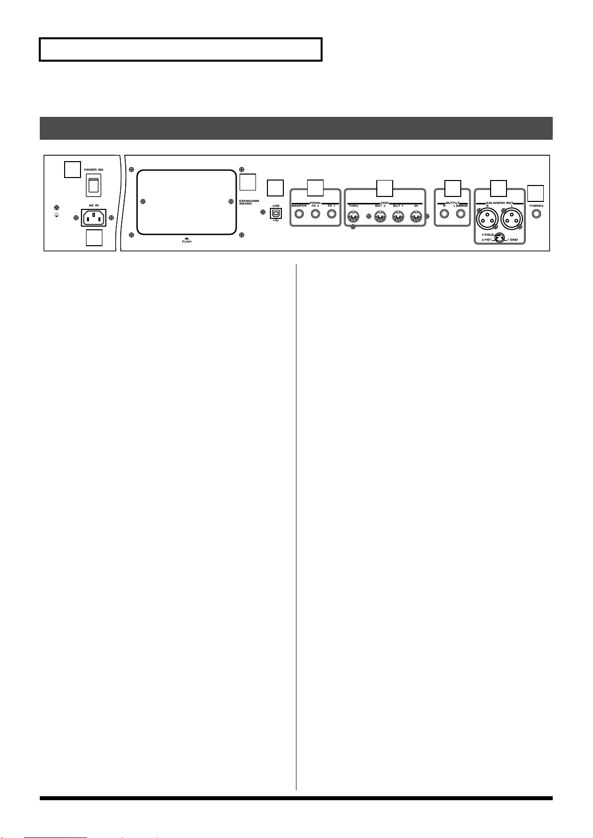
Rear Panel
fig.rear
1
2
1. [POWER ON] Switch
Switch turns the power on/off (p. 23).
2. AC Inlet
Connect the included power cord to this inlet (p. 21).
3
4 5
6
7 8
9
3. Wave Expansion Board Installation Slot
Remove the cover for installation of optional wave expansion boards
(SRX Series) (p. 15).
4. USB Connector
Connect your computer here to exchange Standard MIDI file and
setup file between the computer and the RD-700SX (p. 104).
5. PEDAL Jacks (DAMPER, FC1, FC2)
Connecting the pedal switch (DP series) provided with the RD700SX to the DAMPER jack allows you to use the switch as a damper
pedal.
With a pedal connected to the FC-1 or FC-2 jack, you can then assign
a variety of functions to the pedal (p. 70, p. 84).
6. MIDI Connectors (IN, OUT1, OUT2, THRU)
Used for connecting external MIDI devices and for transmission of
MIDI messages (p. 60, p. 91, p. 101).
7. OUTPUT L (MONO)/R Jacks
Provide output of the audio signals. These are connected to an amp
or other device. For monaural output use the L/MONO jack (p. 21).
8. BALANCED OUT L/R Jacks
Connectors for balanced output of the audio signals. Connect to
mixers and other such gear (p. 21).
9. PHONES Jack
A set of headphones can be connected to this jack (p. 21).
Even when headphones are connected, sound will still be output
from the OUTPUT jacks.
14
Page 15
Getting Ready
Installing the Wave Expansion Board
Up to two optional Wave Expansion Boards (SRX Series) can be installed in the RD700SX.
Wave Expansion Boards store Wave data, Patches, and Rhythm Sets, and by
equipping the RD-700SX with these boards, you can greatly expand your sound
palette.
For more information about the wave expansion board tones, refer to the patch list
included with the wave expansion board. However, some of the tone names may be
displayed differently on the RD-700SX. Check 36page as you refer to the tone names.
Cautions When Installing an Wave Expansion Board
901
1
2
911
912
913
914
915
• To avoid the risk of damage to internal components that can be caused by static
electricity, please carefully observe the following whenever you handle the board.
• Before you touch the board, always first grasp a metal object (such as a water
pipe), so you are sure that any static electricity you might have been carrying
has been discharged.
• When handling the board, grasp it only by its edges. Avoid touching any of the
electronic components or connectors.
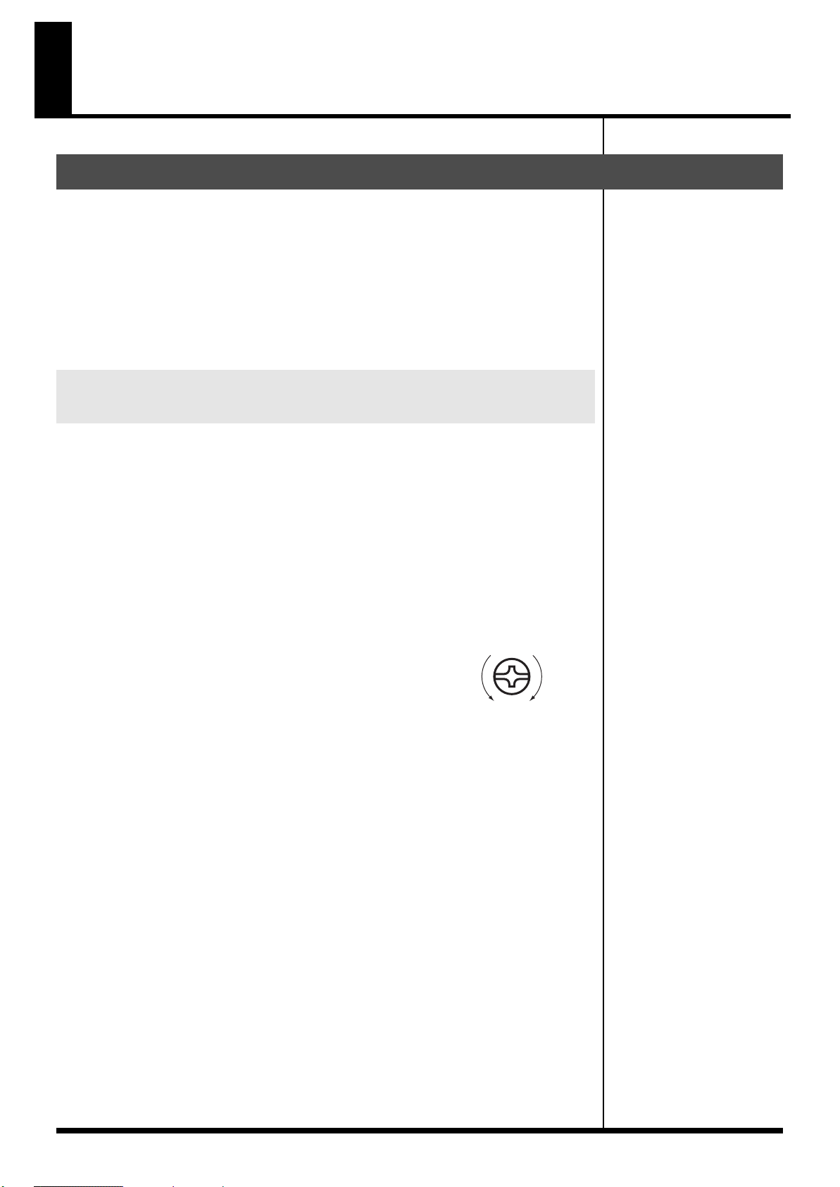
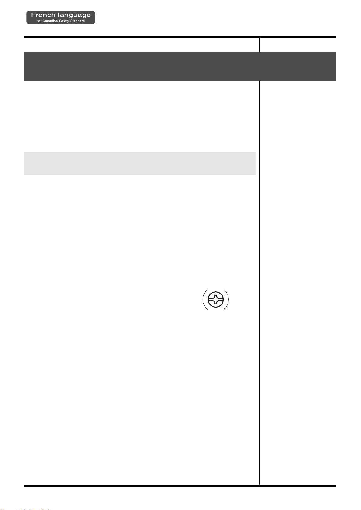
• Use a Philips screwdriver that is suitable for the size of the screw (a number 2
screwdriver). If an unsuitable screwdriver is used, the head of the screw may be
stripped.
• To remove a screw, rotate the screwdriver counterclockwise. To tighten a screw, rotate the screwdriver
clockwise.
• Be careful that the screws you remove do not drop into
the interior of the RD-700SX.
• Do not leave the rear panel cover removed. After installation of the Wave
Expansion Boards is complete, be sure to replace the cover.
• Do not touch any of the printed circuit pathways or connection terminals.
• Never use excessive force when installing a circuit board. If it doesn’t fit properly
on the first attempt, remove the board and try again.
• When circuit board installation is complete, double-check your work.
• Always turn the unit off and unplug the power cord before attempting installation
of the circuit board.
• Install only the specified circuit board(s) (SRX Series). Remove only the specified
screws.
• Be careful not to cut your hand on the edge of the installation bay.
tightenloosen
Install the Wave Expansion Boards after removing the rear panel cover.
There are two slots (A and B) into which a board can be installed. Specify which slot’s
board is to be used by pressing EXPANSION [A] or [B] on the front panel when
using waves, tones, or Rhythm Sets from the wave expansion boards.
15
Page 16
Getting Ready
push
Installing SRX Series Boards
1
Before installing any Wave Expansion Board, turn off the power on
the RD-700SX and all devices connected to it.
2
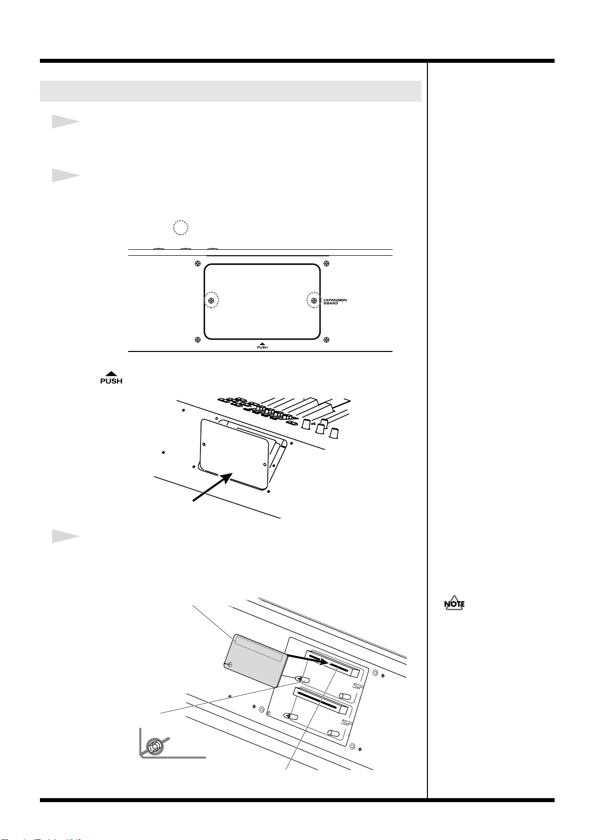
Refer to the following illustration of the RD-700SX’s rear panel, and
remove the screws indicated. Then, remove the cover.
fig.00-02e
Screws to be removed
You can remove the cover easily by pressing on the lower part of the cover (above
the mark).
fig.00-03e
3
Insert the Wave Expansion Board connector into a connector for an
SRX Series slot (SRX A or SRX B), while simultaneously inserting the
board holders into the holes in the Wave Expansion Board.
fig.00-04e
Wave Expansion Board (SRX series)
If the same type of Wave
Expansion Board is installed in
the SRX A slot and the SRX B
slot, it will only be possible to
select data from the Wave
Expansion Board that was
installed in the SRX A slot.
16
Board holder
Position them as shown
before you install the board.
Connector
Page 17
4
2
b
b
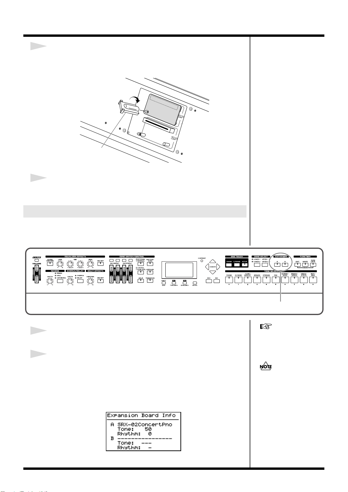
Use the Installation Tool supplied with the Wave Expansion Board to
turn the holders in the LOCK direction, so the board will be fastened
in place.
fig.00-05e
LOCK
Installation tool
5
Use the screws that you removed in step 2 to fasten the cover back in
place.
Getting Ready
Checking the Installed Wave Expansion Boards
After installation of the Wave Expansion Boards has been completed, check to
confirm that the installed boards are being recognized correctly.
fig.00-06p
1
Turn on the power, as described in “Turning On the Power” (p. 23).
“Selecting Wave Expansion
Board Tones” (p. 35).
2
The name of the installed wave expansion board is displayed for as
long as EXPANSION [A] or [B] is held down.
The number of tones and Rhythm Sets contained in the expansion board is
displayed.
The example here depicts what you would see if the SRX-02 “Concert Piano” Wave
Expansion Board were installed in the SRX A slot.
fig.00-07g
If “------” appears next to the
name of the slot in which the
oard was installed, it may be
that the wave expansion board
is not being recognized
properly. Use the procedure in
“Turning Off the Power” (p.
24) to turn the power off, then
reinstall the wave expansion
oard correctly.
By releasing the button, you go back to the previous screen.
17
Page 18
Getting Ready
Installation de la carte d’extension Wave(French language for Canadian Safety Standard)
Vous pouvez installer jusqu’a 2 cartes d’extension optionnelles dans le RD-700SX.
Ces cartes d’extension memorisant des donnees Wave, des morceaux et des
ensembles rythmiques, elles vous permettront d’augmenter considerablement le
timbre.
Pour de plus amples renseignements sur les tonalités de la carte d'expansion Wave,
se reporter à la liste des timbres incluse avec la carte. Toutefois, certains des noms de
tonalités peuvent s'afficher différemment sur le RD-700SX. Consulter la p. 36 pour
les noms des tonalités.
Precautions lors de l’installation de la carte d’extension Wave
901(F)
1
2
911(F)
912(F)
913(F)
914(F)
915(F)
• Veuillez suivre attentivement les instructions suivantes quand vous manipulez la
carte afin d’éviter tout risque d’endommagement des pièces internes par
l’électricité statique.
• Toujours toucher un objet métallique relié à la terre (comme un tuyau par
exemple) avant de manipuler la carte pour vous décharger de l’électricité
statique que vous auriez pu accumuler.
• Lorsque vous manipulez la carte, la tenir par les côtés. Évitez de toucher aux
composants ou aux connecteurs.
• Utiliser un tournevis cruciforme correspondant a la taille de la vis (un tournevis
numero 2). En cas d’utilisation d’un tournevis inapproprie, la tete de la vis pourrait
etre endommagee.
• Pour enlever les vis, tourner le tournevis dans le sens contraire des aiguilles d’une
montre. Pour resserrer, tourner dans le sens des aiguilles d’une montre.
fig.00-01f
• Veillez a ne pas laisser tomber de vis dans le chassis
du RD-700SX.
• Ne pas laisser la plaque arriere detachee. Apres
avoir installe la ou les carte(s) d’extension, bien
remettre la plaque en place.
• Ne pas toucher aux circuits imprimés ou aux connecteurs.
• Ne jamais forcer lors de l’installation de la carte de circuits imprimés. Si la carte
s’ajuste mal au premier essai, enlevez la carte et recommencez l’installation.
• Quand l’installation de la carte de circuits imprimés est terminée, reverifiez si tout
est bien installé.
• Toujours éteindre et debrancher l’appareil avant de commencer l’installation de la
carte.
• N’installez que les cartes de circuits imprimes specifiees (SRX Series). Enlevez
seulement les vis indiquees.
• Installer les cartes d’extension apres avoir enleve la plaque arriere.
• Veillez a ne pas vous couper les doitgs sur le bord de l’ouverture d’installation.
resserrerdesserrer
18
Avant d'installer la carte d'expansion Wave, retirer le panneau arrière.
Il y a deux emplacements (A et B) dans lesquels une carte peut être installée. Spécifier
l'emplacement à utiliser en appuyant sur EXPANSION [A] ou [B] sur le panneau
avant lors de l'utilisation d'ondes, de tons ou de groupes rythmiques à partir des
cartes d'expansion Wave.
Page 19
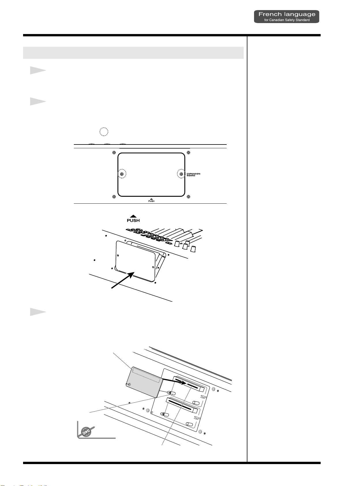
Installer les cartes de serie SRX
push
1
Avant d’installer une carte d’extension Wave, eteindre tous les
appareils relies au RD-700SX.
2
Detacher la plaque arriere en enlevant les vis indiquees sur le schema
suivant.
fig.00-02f
Vis à enlever
Getting Ready
Il est facile d’enlever le couvercle: il suffit d’appuyer sur la partie inférieure du
couvercle (au-dessus du symbole ).
fig.00-03f
3
Inserer le connecteur de la carte dans un des creneaux pour la serie
SRX (SRX A, SRX B) tout en enfoncant les supports a carte dans les
trous de celle-ci.
fig.00-04f
Carte d'extension Wave (serie SRX)
Support à carte
Avant l’installation, orienter les supports
à carte tel qu’indiqué sur le schéma.
Connecteur
19
Page 20
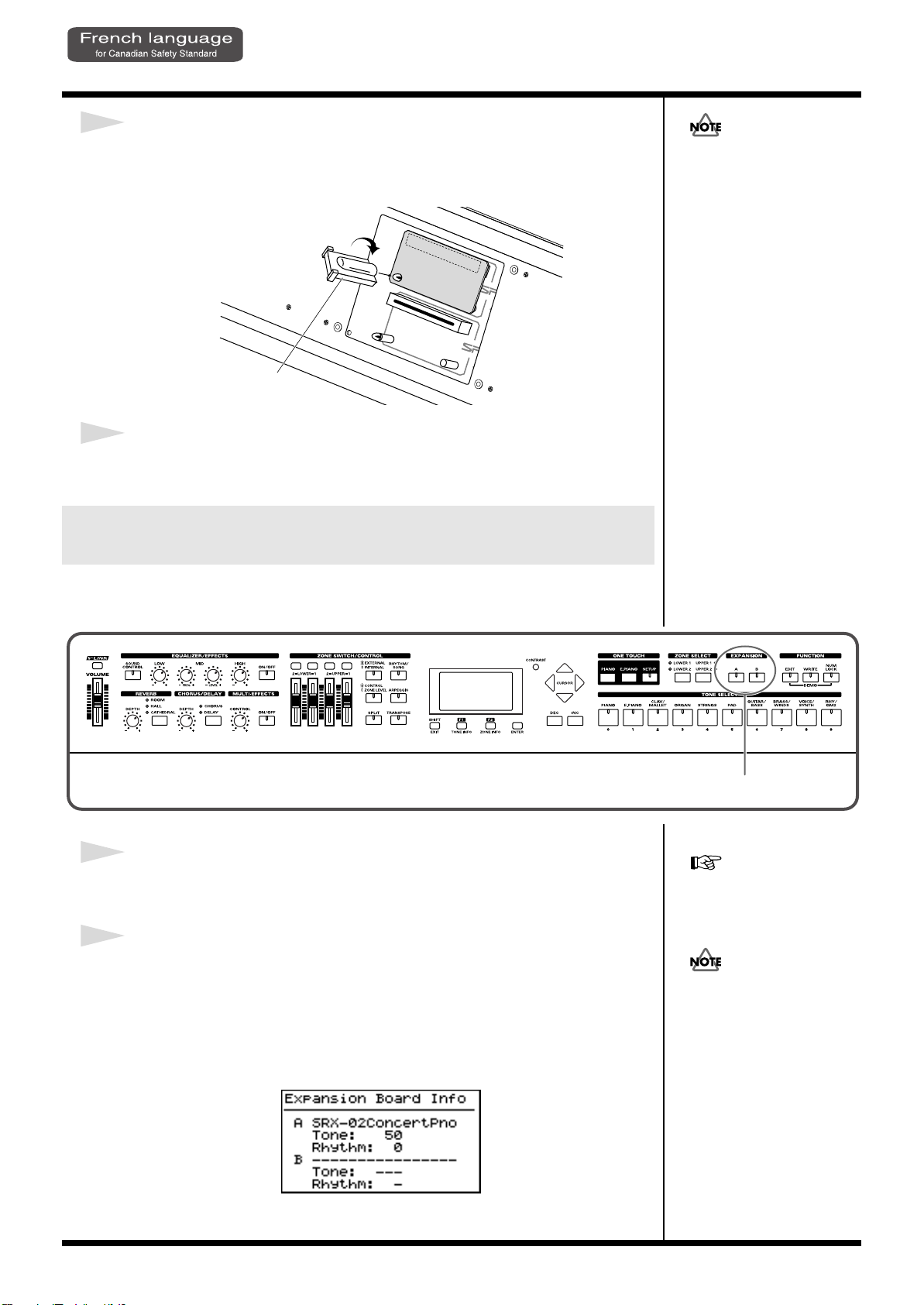
Getting Ready
2
4
Pour tourner les supports en position LOCK (verrouille), utilisez l’outil
d’installation de la carte d’extension fournie a cet effet. De cette
facon, la carte sera bien fixee a sa place.
fig.00-05f
LOCK
Outil d'installation
5
Reposez le couvercle en remettant les vis enlevees (comme specifie)
a l’etape 2.
Verification des cartes d’extension audio apres
Si la meme sorte de carte
d’extension Wave est installee
dans les creneaux SRX A et
SRX B, il ne sera possible de
selectionner que les donnees
de la carte d’extension Wave
installee dans le creneau SRX
A.
installation
Lorsque l’installation des cartes d’extension audio est terminee, proceder a une
verification pour s’assurer que l’ordinateur les identifie correctement.
fig.00-06p
1
Mettre sous tension de la facon decrite sous “Turning On the Power”
(p. 23).
2
Le nom de la carte d'expansion Wave installée s'affiche tant que la
touche EXPANSION [A] ou [B] est tenue enfoncée.
Le nombre de tonalités et de groupes rythmiques compris sur la carte d'expansion
s'affiche.
L’exemple montre ce qui serait affiche si la carte d’extension audio SRX-02 “Concert
Piano”etait installee dans la fente SRX A.
fig.00-07g
“Selecting Wave Expansion
Board Tones” (p. 35).
Si “----------------” est affiche a
cote du nom de la fente dans
laquelle la carte est installee, il
est possible que la carte
d’extension audio installee ne
soit pas reconnue
correctement. Mettre hors
tension de la facon decrite sous
“Turning Off the Power” (p.
24) et reinstaller correctement
la carte d’extension audio.
20
Lorsque vous le relacherez, vous serez ramene a l’ecran precedent.
Page 21
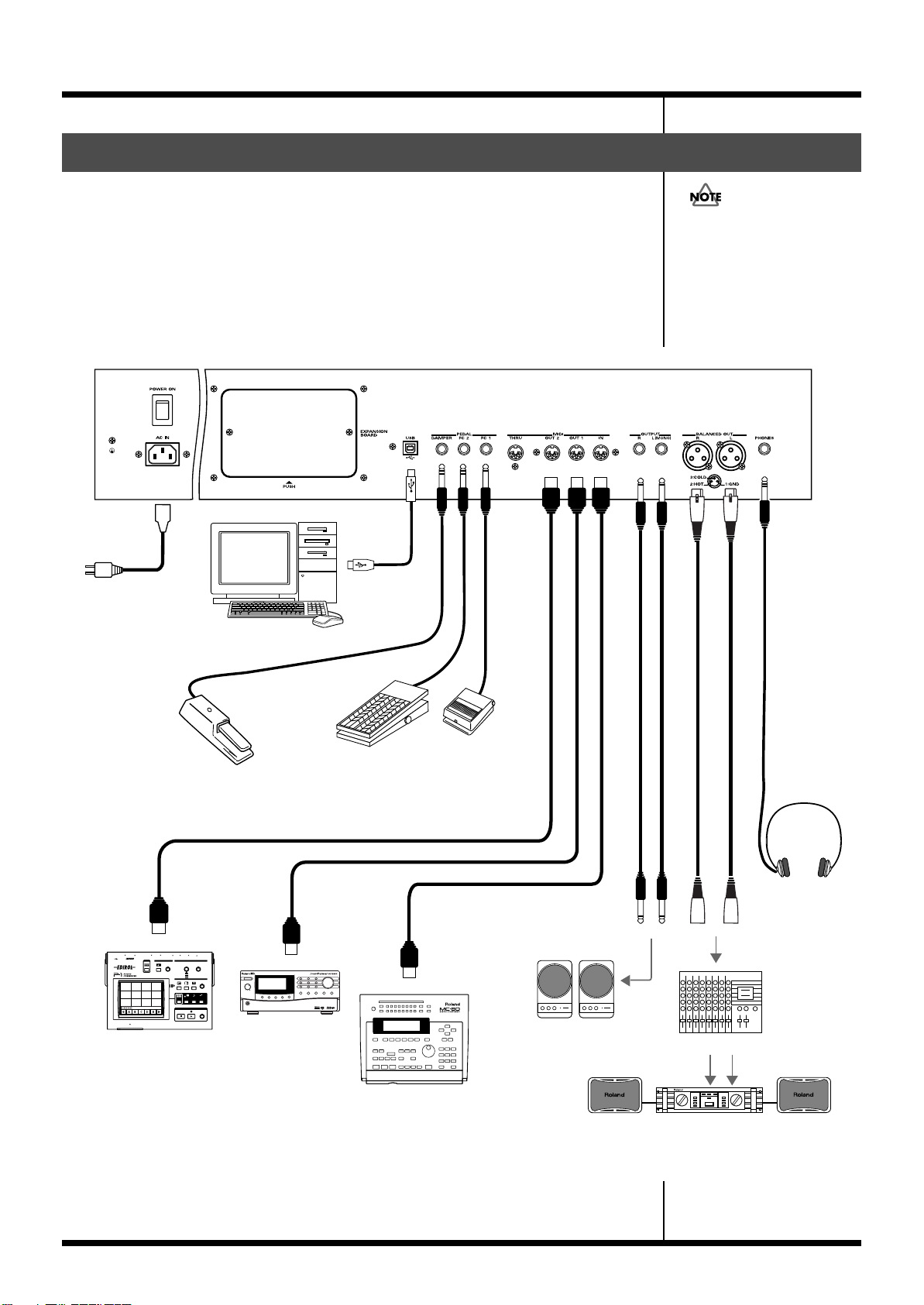
Getting Ready
MIDI IN
MIDI IN
MIDI sound module etc.
V-LINK-compatible
video equipment.
MIDI OUT
MIDI sequencer etc.
Stereo
headphones
to Power outlet
Mixer etc.
Power amp.
Monitor speakers
(powered)
Expression pedal (EV-5/7)
or Pedal switch (DP-2/8)
Pedal switch
(DP-2/8)
Computer
Connecting the RD-700SX to External Equipment
The RD-700SX is not equipped with an amplifier or speakers. In order to produce
sound, you need to hook up audio equipment such as a monitor speaker or a stereo
set, or use headphones.
* Audio cables, MIDI cables, USB cables, headphones, and expression pedals are not included.
Consult your Roland dealer if you need to purchase accessories such as these.
fig.00-08e
To prevent malfunction and/
or damage to speakers or other
devices, always turn down the
volume, and turn off the
power on all devices before
making any connections.
921
21
Page 22
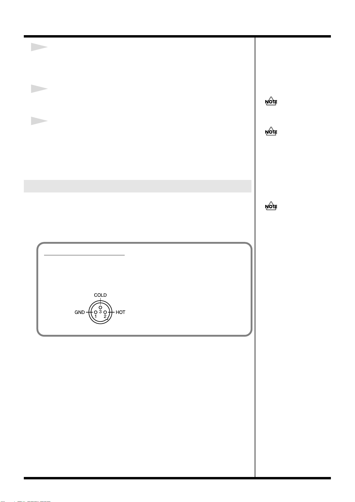
Getting Ready
About the Output Jacks
922
This instrument is equipped with balanced (XLR) type jacks. Wiring diagrams for
these jacks are shown below. Make connections after first checking the wiring
diagrams of other equipment you intend to connect.
fig.XLRJack
1
Before you begin making connections, confirm the following.
Is the volume level of the RD-700SX or connected amp turned all the way down?
Is the power to the RD-700SX or connected amp turned off?
2
Connect supplied power cord to the RD-700SX, and plug the other end
into an AC power outlet.
3
Connect the RD-700SX and the external device.
Use audio cables to connect audio equipment, such as an amp or speakers. Use MIDI
cables to connect MIDI devices. Use USB cables to connect computer.
If you are using headphones, plug them into the PHONES jack.
Connect pedal switches or expression pedals as necessary.
Connecting Pedals
Connect the pedal included with the RD-700SX to one of the PEDAL jacks.
When connected to the DAMPER jack, the pedal can be used as a damper pedal.
Connecting the pedal to the FC-1 or FC-2 jack allows you to assign a variety of
functions to the pedal (p. 70, p. 85).
Use Stereo headphones.
Use only the specified
expression pedal (EV-5/7; sold
separately). By connecting any
other expression pedal, you
risk causing malfunction and/
or damage to the unit.
5
Set the switch on the included
pedal to “Continuous” when
the pedal is connected.
22
Page 23
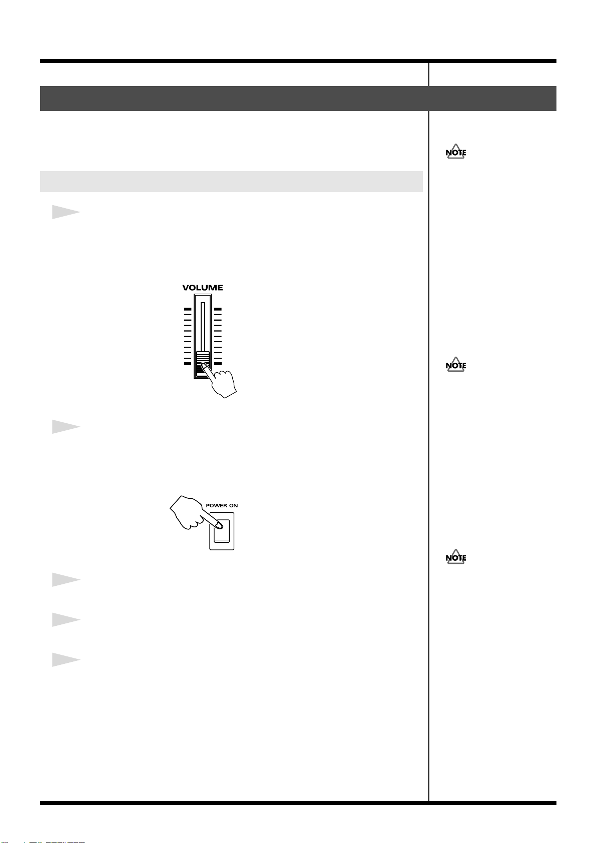
Turning the Power On and Off
To prevent incorrect
functioning of the Pitch Bend/
Modulation Lever (p. 44),
refrain from touching the lever
while the power to the RD700SX is turned on.
941
Once the connections have been completed, turn on power to your various devices
in the order specified. By turning on devices in the wrong order, you risk causing
malfunction and/or damage to speakers and other devices.
Turning On the Power
1
Before you switch on the power, move the volume down all the way by
moving the VOLUME Slider.
Also completely turn down the volume of any connected audio device and other
equipment.
fig.00-09
Getting Ready
In the unlikely event the
power is turned off or cut off
while Factory Reset (p. 22) is
in progress, the data may
become corrupted, and it
may require additional time
for the unit to start up the
next time.
2
Press the upper portion of the [POWER ON] switch on the back of the
RD-700SX to turn on the power.
The unit is powered up, and the display’s backlighting comes on.
fig.00-10
3
Turn on the power to connected external devices.
4
Adjust the volume of the connected external device.
5
Adjust the RD-700SX’s volume to obtain the proper volume level.
This unit is equipped with a
protection circuit. A brief
interval (a few seconds) after
power up is required before
the unit will operate normally.
942
23
Page 24
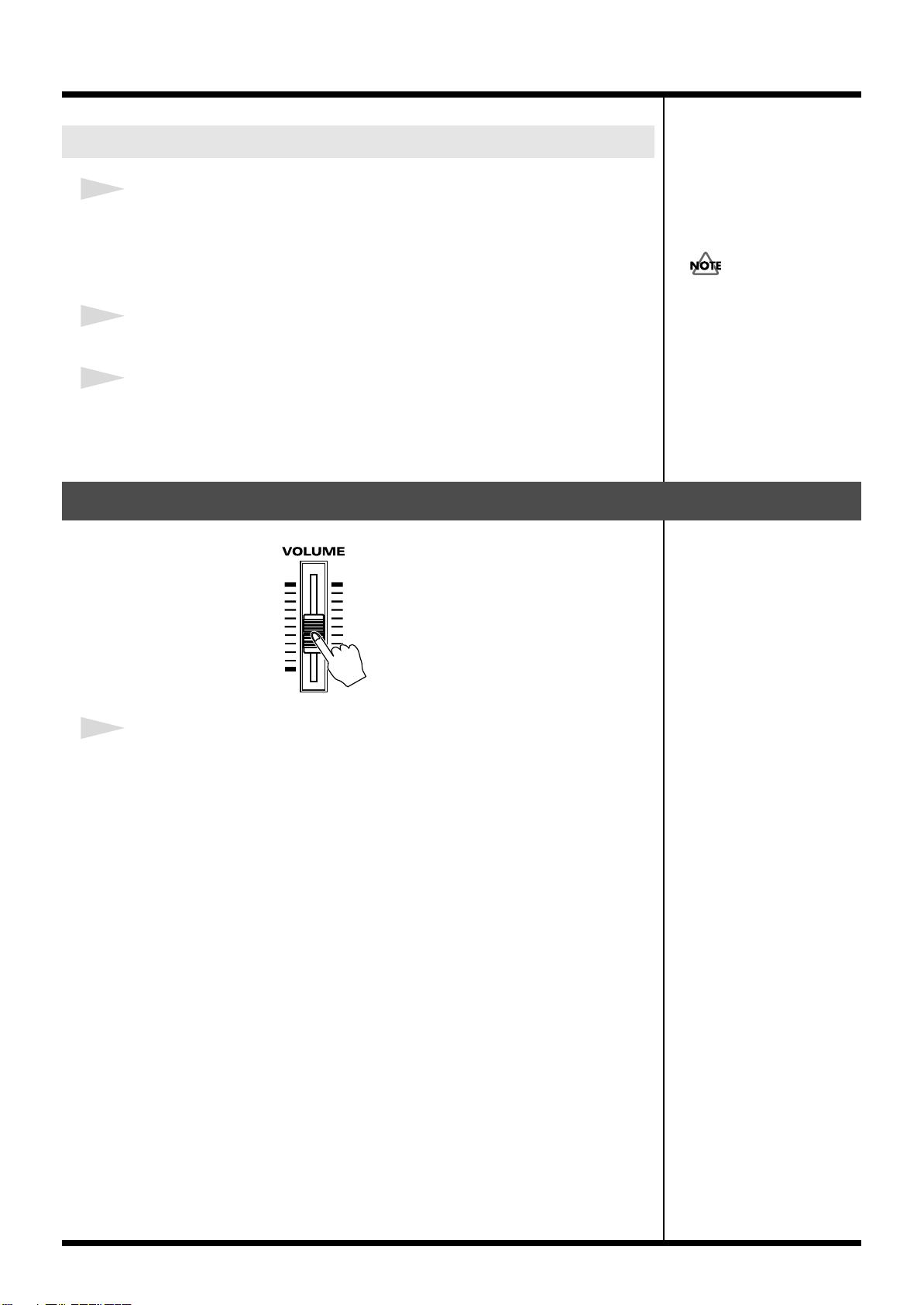
Getting Ready
Turning Off the Power
1
Before you switch on the power, move the volume down all the way by
moving the VOLUME Slider.
Also completely turn down the volume of any connected audio device and other
equipment.
2
Turn off the power to connected external devices.
3
Press the lower portion of the [POWER ON] switch on the back of the
RD-700SX.
The power is switched off.
Adjusting the Volume
If you need to turn off the
power completely, first turn
off the POWER switch, then
unplug the power cord from
the power outlet.
Refer to “Power Supply” (p.
5).
fig.00-11
1
Adjust the volume using the VOLUME slider.
Move the slider up to increase the volume, or down to lower it.
Also adjust the volume of the connected device to an appropriate level.
24
Page 25
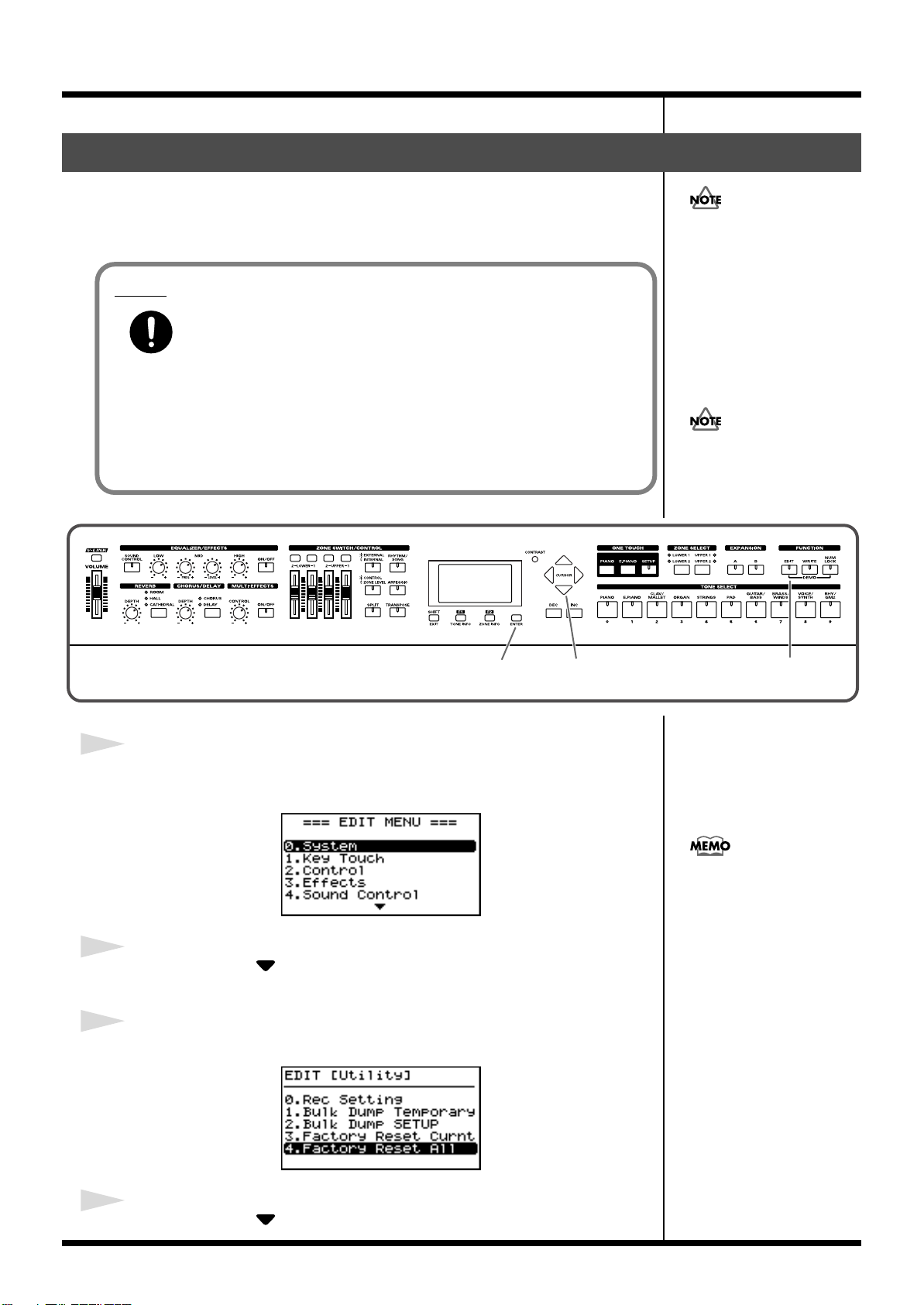
Restoring the Factory Settings (Factory Reset)
12,43,5,6,7
When using the RD-700SX for the first time, start by returning the settings to their
factory defaults so that the RD-700SX operates as described in the procedures in the
owner’s manual.
Notes
Never turn off the power during Factory Reset (while “Now, Executing”
appears in the display).
Turning off the power while Factory Reset is in progress may result in
corrupted internal data and may prevent the power from being turned on again. If
you have confirmed that the internal data has been lost, or if a similar problem exists,
consult the retailer from whom you purchased the instrument, or the nearest Roland
Service Center. Note, however, that Roland assumes no liability, including
compensation, for consequences arising from any loss of data.
fig.00-12p
Executing this operation
deletes the Setup settings (p.
56). If you want to keep any
internally stored content, use
the “Bulk Dump (Bulk Dump
SETUP)” procedure to save the
data to an external sequencer
(p. 99).
When making USB
connections, be absolutely
sure to disconnect the USB
cable before starting.
Getting Ready
1
Press [EDIT], getting the indicator to light.
The Edit Menu screen appears.
fig.00-13g
2
Press CURSOR [ ] to select “9.Utility.”
3
Press [ENTER] to display the Utility screen.
fig.00-14g
Instead of selecting with the
CURSOR, you can press TONE
SELECT [9] to display the
Utility Edit screen directly.
4
Press CURSOR [ ] to select “Factory Reset All.”
25
Page 26
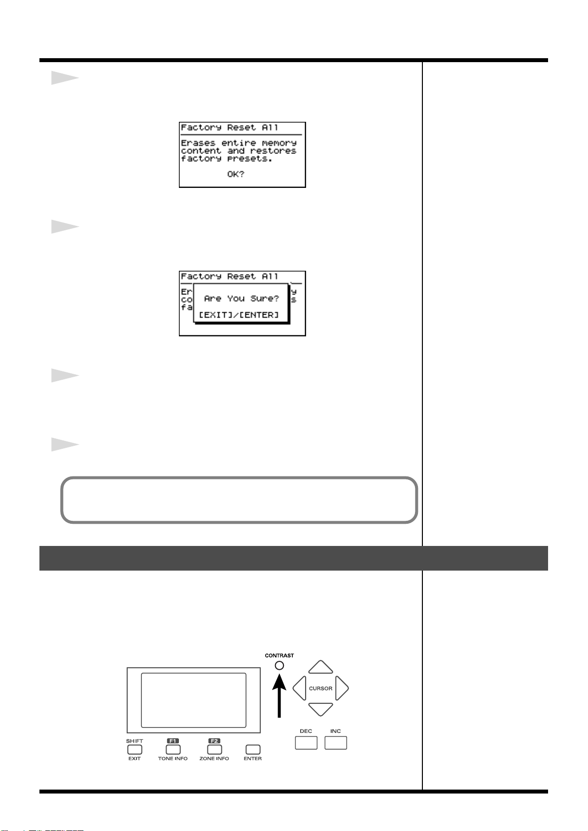
Getting Ready
5
Press [ENTER].
A screen like the one shown below appears.
fig.00-15g
To cancel the Factory Reset, press [EXIT].
6
Press [ENTER].
The confirmation message appears.
fig.00-16g
To cancel the Factory Reset, press [EXIT].
7
Press [ENTER] once again to start the Factory Reset operation.
During the execution, “Executing... Don’t Power OFF” appears in the display.
After the Factory Reset operation is finished, the ONE TOUCH screen will appear.
8
Turn off the power to the RD-700SX, then turn it on again.
You can also restore only part of the setting to their factory status. Refer to
“Restoring the settings to the factory condition (Factory Reset)” (p. 100).
Adjusting the Display Contrast (LCD Contrast)
The characters in the display may be difficult to view immediately after turning on
the power or after extended use; this may also be because of where and how the
display is situated.
In such instances, adjust the display contrast by turning the CONTRAST knob on the
front panel.
fig.00-17p
26
Page 27
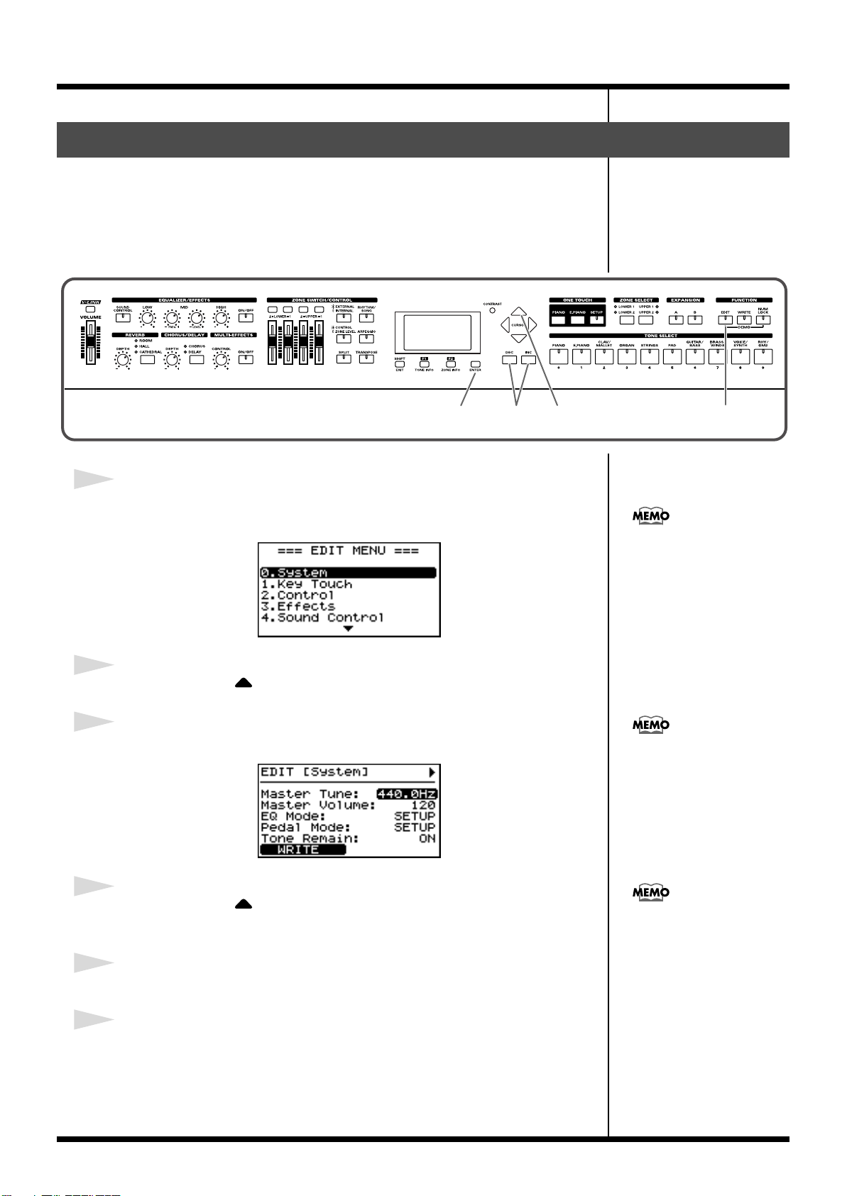
Getting Ready
You can directly display the
System Edit screen by pressing
TONE SELECT [0] instead of
selecting with CURSOR.
Tuning to Other Instruments’ Pitches (Master Tune)
For a cleaner ensemble sound while performing with one or more other instruments,
ensure that each instrument’s basic pitch is in tune with that of the other
instruments. In general, the tuning of an instrument is indicated by the pitch in Hertz
(Hz) of the middle “A” note.
This matching of other instruments’ basic reference pitches is called “tuning.”
fig.00-18ps
1
Press [EDIT], getting the indicator to light.
The Edit Menu screen appears.
fig.00-19g
2
Press CURSOR [ ] to select “0.System.”
3
Press [ENTER] to display the Edit screen.
fig.00-20g
5
For faster value increases, keep
[INC] pressed down and press
[DEC]. For decreasing value
faster, keep [DEC] pressed
down and press [INC].
1,62,43
4
Press CURSOR [ ] to move the cursor to the “Master Tune”
parameter.
5
Press [INC]/[DEC] to select the value (415.3–440.0–466.2).
6
Press [EDIT] to make the indicator go dark.
You are returned to the Tone screen.
If you want to save this setting,
press [F1(WRITE)]. Settings
saved in the RD-700SX are not
deleted even when the power
is turned off.
27
Page 28
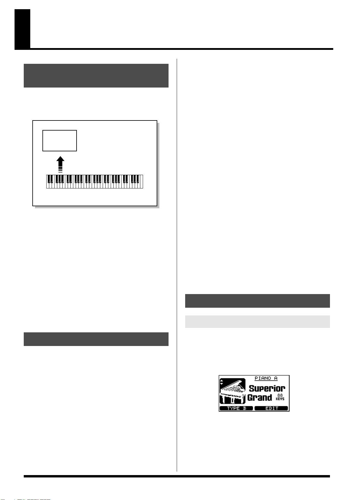
Overview of the RD-700SX
Part
Basic Organization of the RD-700SX
The RD-700SX can be divided into two sections: a keyboard
controller section and a sound generator section. The two
sections are connected internally by means of MIDI.
fig.00-G01e
Sound
Generator
Section
A sound generator of this type which can control multiple
sounds using one device is referred to as a multitimbral sound
generator. The RD-700SX contains a multitimbral sound
generator capable of playing sixteen Tones simultaneously.
“Parts” are where Tones that are created when the RD-700SX is
used as a sound generator are assigned. Since different Tones
can be assigned to each of the Parts and controlled individually,
you can have multiple Tones play simultaneously, divide the
keyboard into separate ranges and have different Tones sound
in the different parts (Split), and enjoy playing ensemble
performances.
The sixteen Parts played by the RD-700SX’s internal sound
generator are referred to as “Internal Parts.”
Play
Keyboard Controller Section
(controllers such as keyboard, pitch bend lever, etc.)
Keyboard Controller Section
This section includes the keyboard, the Pitch Bend/Modulation
Lever, the panel knobs, the sliders, and any pedal connected to
the rear panel. Actions such as pressing and releasing of keys on
the keyboard, depressing a pedal, and so forth, are converted to
MIDI messages and sent to the sound generator section, or to an
external MIDI device.
Sound Generator Section
The sound generator section produces the sound. Here, MIDI
messages received from the keyboard controller section or
external MIDI device are converted to musical signals, which are
then output as analog signals from the OUTPUT and PHONES
jacks.
Zone
The RD-700SX features four Parts (UPPER1, UPPER2, LOWER1,
and LOWER2) that you can use for freely controlling the Internal
Parts with the RD-700SX’s buttons and keyboard. These four
Parts that are used for controlling the Internal Parts are
collectively known as the “INTERNAL Zone.” Four of the
sixteen Internal Parts are assigned to the INTERNAL Zone for
control (the RHYTHM Part is fixed at Part 10).
Furthermore, you can freely control external MIDI sound
generators with the RD-700SX in the same manner as with the
INTERNAL Zone. You can likewise control the external MIDI
sound generator with the four Parts (UPPER1, UPPER2,
LOWER1, and LOWER2), with this group of four Parts being
referred to as the “EXTERNAL Zone.” The external MIDI sound
generator is assigned to these three Parts for control (the
RHYTHM Part can also be partially set).
Basic Operation
Main Screens
Units of Sound
When using the RD-700SX, you will notice that a variety of
different categories come into play when working with sounds.
What follows is a simple explanation of each sound category.
Tone
The individual sounds used when playing the RD-700SX are
referred to as “Tones.” The RD-700SX provides 488 types of
Tones. Tones are assigned to each part.
The Tones also include various groups of percussion instrument
assembled into “Rhythm Sets.” Each key (note number) of a
Rhythm Set will produce a different percussion instrument.
28
ONE TOUCH Screen
When ONE TOUCH [PIANO] or [E.PIANO] is pressed, setting
the RD-700SX to the optimal status for piano performances, this
screen is displayed.
fig.00-G03g
Page 29
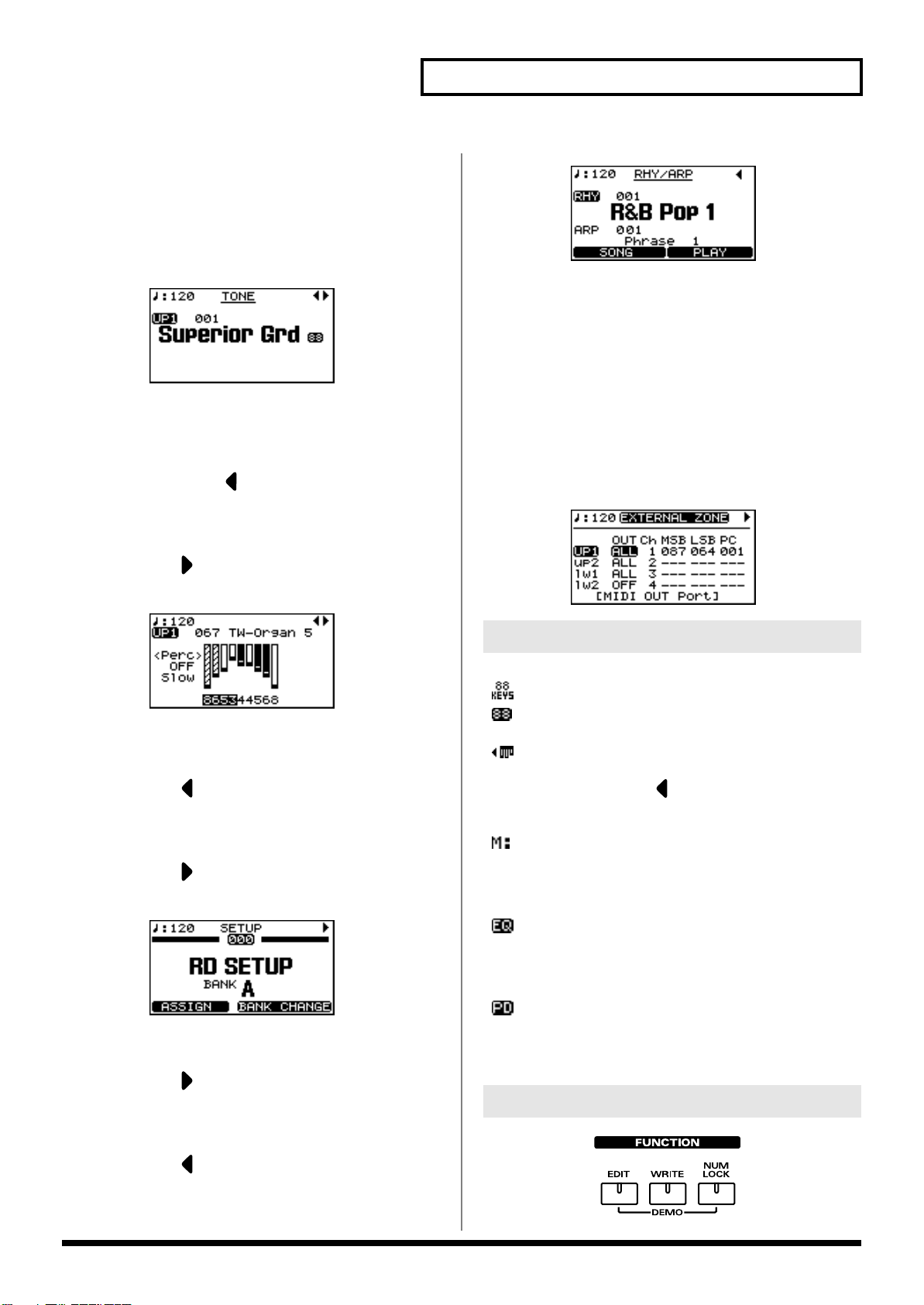
Overview of the RD-700SX
The Tone Screen (Basic Screen)
The names of the Tones currently selected for the INTERNAL
Zone are displayed. This is the screen that is ordinarily
displayed.
You can change the INTERNAL Zone (UPPER1, UPPER2,
LOWER1, and LOWER2) Tones and tempo.
fig.00-G02g
The Tone Wheel Screen
In the Tone screen, when any ORGAN Tone “Tone Wheel 1-10”
is selected for any of the INTERNAL Zone, this screen is
displayed when CURSOR [ ] is pressed. The mode when this
screen is displayed is called “Tone Wheel mode,” and while in
this mode you can simulate the creation of sounds using an
organ’s harmonic bars (p. 53).
Pressing CURSOR [ ] when this screen is displayed returns
you to the Tone screen.
fig.00-G04g
fig.00-G06g
EXTERNAL Screen
When [EXTERNAL/INTERNAL] is pressed, the button’s
indicator lights up, and the RD-700SX switches to the mode
enabling it to control an external MIDI sound generator. The
status of this button determines whether the RD-700SX’s buttons
are used to control the INTERNAL Zone ([EXTERNAL/
INTERNAL] unlit), or to control the EXTERNAL Zone
([EXTERNAL/INTERNAL] lit).
In addition, you can make detailed settings for the MIDI
messages to be transmitted to the external sound generator (p.
61).
fig.00-G06g
The Setup Screen
The currently selected Setup is displayed (p. 56).
Pressing CURSOR [ ] when the Tone screen or Tone Wheel
Screen is displayed switches the RD-700SX to this screen. You
can also have this screen displayed by pressing [SETUP]. You
can change the Setups (p. 46, p. 48, p. 50).
Pressing CURSOR [ ] when this screen is displayed returns
you to the Tone screen or Tone Wheel Screen.
fig.00-G05g
The Rhythm/Song/Arpeggio Screen
Pressing CURSOR [ ] when the Tone screen is displayed
switches the RD-700SX to this screen.
You can change Song, Rhythm patterns, Arpeggio patterns, and
the tempo.
Special Indications
fig.mark-tempoM
A mark is displayed to the right of the tone name when
you select an 88-key multisampled piano tone in the
Tone screen.
fig.mark-tempoM
A mark is displayed to the left of the tone name when
you select “TW-Organ 1–10” in the Tone screen.
Pressing CURSOR [ ] while this mark is displayed
brings up the Tone Wheel screen (p. 53).
fig.mark-tempoM
With Clock Source (p. 81) set to MIDI, the tempo
indication changes to “M:” for each screen.
The tempo can be changed with the external MIDI
devices when this mark is indicated.
fig.mark-EQ
With EQ Mode (p. 80) set to SYSTEM, this mark
appears upper right on the screen.
Equalizer settings do not change when Setups are
switched while this mark is indicated.
fig.mark-PD
With Pedal Mode (p. 80) set to “SYSTEM,” this mark
appears on the upper right of the screen.
Pedal settings do not change when Setups are switched
while this mark is indicated.
About the Function Buttons
fig.00-G07p
Pressing CURSOR [ ] when this screen is displayed returns
you to the Tone screen.
29
Page 30
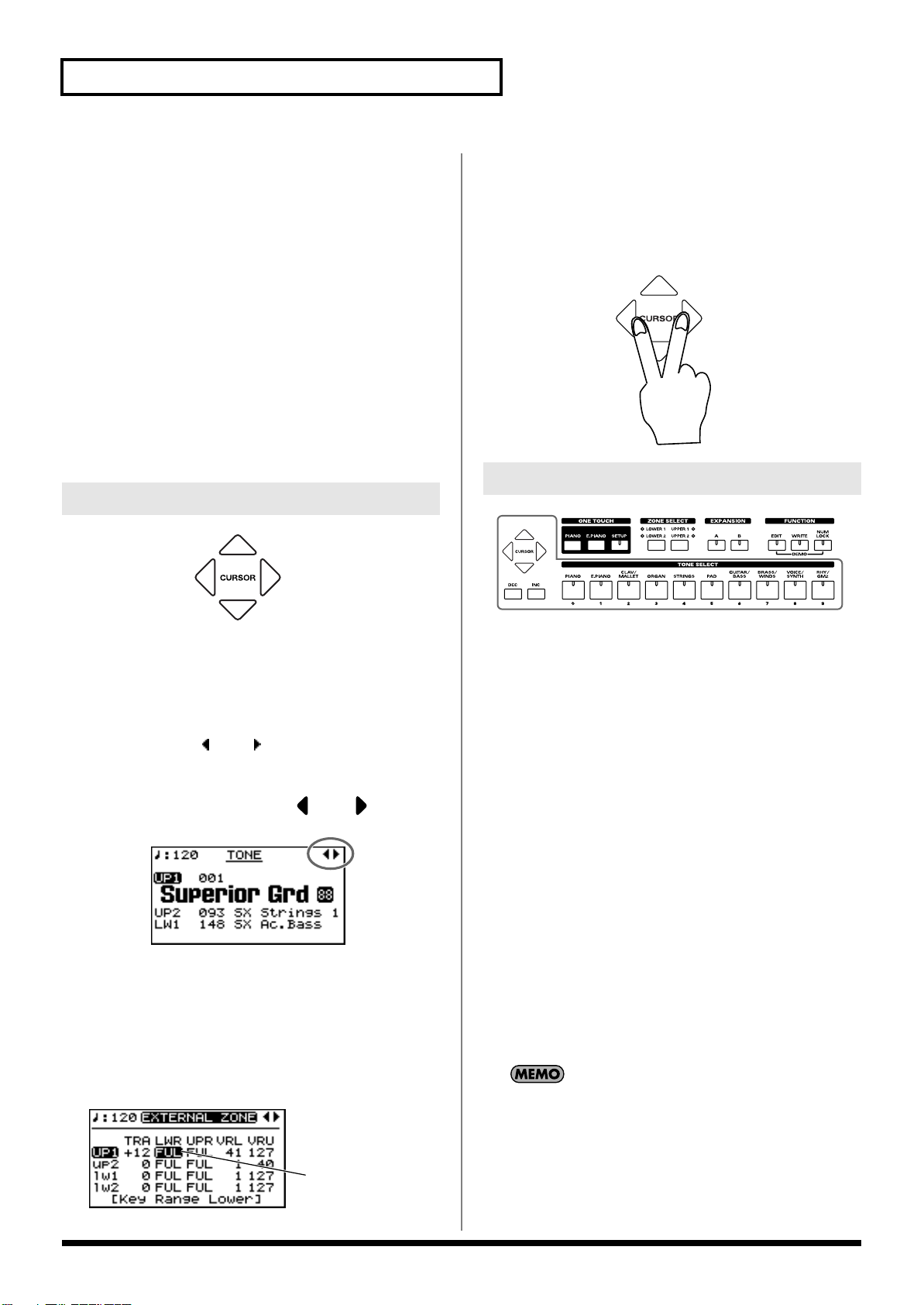
Overview of the RD-700SX
[EDIT]
By pressing [EDIT] to make the indicator light, you can enter
“Edit mode.” In Edit mode you can make detailed settings for
various functions.
You can exit Edit mode by pressing [EDIT], extinguishing its
indicator.
[WRITE]
Stores the current settings to “Setup” (p. 58).
[NUM LOCK]
When [NUM LOCK] is pressed, the button’s indicator lights up,
enabling input of numerical values using the TONE SELECT
buttons. The button indicators automatically light according to
the values set.
About the CURSOR Buttons
fig.00-G08p
Additionally, when multiple parameters are presented
horizontally in a row, as shown in the EXTERNAL screen, you
can get the cursor to move more rapidly by holding down the
CURSOR button that points in the direction you want the cursor
to move while you also press the CURSOR button that points in
the opposite direction.
fig.00-G11pj
Changing the Settings Values
fig.00-G12p
The CURSOR buttons are used for switching screens, and for
moving to an item whose setting you want to change (by
moving the cursor).
Moving Between Display Pages
When arrow symbols (“ ” and “ ”) appear at the upper right of
the display screen, it indicates that there are additional pages in
the directions shown by the arrows.
You can switch screens with CURSOR [ ] and [ ].
fig.00-G09g
Navigating Among Items To Be Set
(CURSOR)
When more than one parameter is present in a screen, the name
and value of the parameter to be changed is shown with a box
around it. This box is referred to as the “cursor.” The cursor is
moved with the CURSOR buttons.
fig.00-G10g
Cursor
When changing settings values, you can use [DEC] and [INC], or
the TONE SELECT buttons (numeric keys).
[DEC], [INC]
Pressing [INC] increases the value, and [DEC] decreases it. Keep
the button pressed for continuous adjustment. For faster value
increases, keep [INC] pressed down and press [DEC]. For
decreasing value faster, keep [DEC] pressed down and press
[INC].
Simultaneously pressing [DEC] and [INC] sets that parameter to
the standard default value or switches it off.
TONE SELECT Buttons
(Numeric Keys)
When [NUM LOCK] is on (lit), numerical values can be input
directly using the TONE SELECT buttons, which then serve as
[0]–[9] numeric keys. When you enter the number, the value will
blink. This indicates that the value has not yet been finalized. To
finalize the value press [ENTER].
With some parameters, [NUM LOCK] may come on
automatically, allowing you to input numerical values directly
with the TONE SELECT buttons.
Only numerical values can be entered using the numeric keys.
To switch the positive (+) or negative (-) signs for numerical
values and make continuous changes in the numerical values,
press [INC] or [DEC].
30
Page 31

Listening to the Demo (DEMO PLAY)
No data for the music that is
played will be output from the
MIDI OUT connector.
982
Here’s how to listen to these songs.
The RD-700SX features the internal demo songs that exhibit the special capabilities
of the instrument.
No. Song Name Composer/Copyright
01. Take a Break Scott Tibbs © 2004 Roland Corporation
02. Superior Grand Scott Tibbs © 2004 Roland Corporation
03. Everything Cool Scott Tibbs © 2004 Roland Corporation
04. Tone Preview Scott Tibbs © 2004 Roland Corporation
Demo song 04 “Tone Preview” makes effective use of the internal tones. A total of
ten pieces are offered, one for each TONE CATEGORY.
fig.Q1-01p
All rights reserved.
Unauthorized use of this
material for purposes other
than private, personal
enjoyment is a violation of
applicable laws.
981a
1234,5
* When demo songs are playing back, all settings are switched to their status at the time the
RD-700SX’s power was turned on. Store any arrangements of settings that you want to keep
in Setup (p. 58).
1
Hold down [NUM LOCK] and press [EDIT].
The Demo screen appears.
fig.Q1-02g
2
Press CURSOR [ ] / [ ] or [INC] / [DEC] to select the song that
you wish to hear.
3
Press CURSOR [F2(PLAY)] or [ENTER] to start playback of the demo
song.
Press any one of the TONE SELECT buttons, and playback begins from the demo
song corresponding to the button pressed.
When all songs have been played, playback will return to the first song and resume.
Pressing a TONE SELECT button during playback stops the song being played, and
playback of the newly selected song begins.
4
Press CURSOR [EXIT] or [F1(MENU)] to stop a song during playback.
Regardless of whether the
song is playing or stopped,
pressing ONE TOUCH
[PIANO] or [E.PIANO] ends
the demo and returns the
original screen to the display.
5
Press [EXIT] or [F1(EXIT)] while the song is stopped to finish with the
Demo screen.
You are returned to the Tone screen.
31
Page 32

Performing with the Keyboard
Pressing ONE TOUCH
[PIANO] or [E.PIANO]
restores all of the settings
except for the Piano Edit(p. 73)
or Electric Piano Edit(p. 76)
settings to their status at the
time the power was turned on.
If you want to preserve these
settings, record them to a
setup(p. 56).
Piano Performances (ONE TOUCH)
Now, try performing with the piano.
With the RD-700SX, you can call up the optimal settings for piano performances with
the press of a single button.
You can also select your preferred tones and settings and store them to the
instrument’s buttons.
fig.Q1-03p
12
1
Press ONE TOUCH [PIANO] or [E.PIANO].
fig.Q1-04g
Pressing ONE TOUCH [PIANO] sets the entire keyboard to play with the piano
tone.
Pressing ONE TOUCH [E.PIANO] sets the entire keyboard to play with the electric
piano tone.
2
You can now press [F1] to switch the type.
Pressing [F1] toggles you between Types A and B.
fig.Q1-05g
You can use CURSOR [ ]/
[ ] in the ONE TOUCH
(PIANO) screen to adjust the
amount the grand piano lid is
opened.
With the RD-700SX, you can also make more detailed settings to make the sound
even better match your favorite piano performances. You can store a total of four
32
settings configurations, two each to [PIANO] and [E.PIANO].
Please refer to each as needed.
• Fine Adjustment of Piano Tones (Piano Edit) →p. 73
• Fine Adjustment of E.Piano Tones (E.Piano Edit) →p. 76
• Fine Adjustment of the Piano Touch Sense →p. 74
Page 33

Performing with a Variety of Tones
If multiple tones are playing,
do not press the ONE TOUCH
[PIANO] button, but instead
select the zone containing the
tone to be changed using the
ZONE SELECT buttons. Refer
to
“Changing the Tone for a
Zone” (p. 40).
b
The RD-700SX provides 488 types of Tones.
Each one of these individual sounds is called a “tone.”
Tones are assigned to the TONE SELECT buttons according to the tone category
selected.
Try selecting and performing with a number of different tones.
fig.Q1-06p
32
1
1
Press ONE TOUCH [PIANO] or [E.PIANO].
This selects a single tone to be played over the entire keyboard.
Performing with the Keyboard
“Tone List” (p. 146)
2
Press any of the TONE SELECT buttons to select the tone category.
The TONE SELECT button for the selected category lights.
3
Press [INC]/[DEC] to select the tone.
Play the keyboard, and you will hear the selected tone.
The next time you choose this TONE SELECT button, the tone you’re selected here
is played.
If [NUM LOCK] is turned on,
the Tone Category cannot be
selected with TONE SELECT
utton. For details, refer to p.
34.
Tones selected with [RHY/
GM2] are registered in the
following order: “Rhythm
Sets,” “GM2 Rhythm Sets,”
and “GM2 Tones.” Refer to the
“Tone List” (p. 146).
33
Page 34

Performing with the Keyboard
If multiple tones are playing,
do not press the ONE TOUCH
[PIANO] button, but instead
select the zone containing the
tone to be changed using the
ZONE SELECT buttons. Refer
to
“Changing the Tone for a
Zone” (p. 40).
Specifying the Tone Number to Select a Tone ([NUM LOCK])
Each individual tone has a different tone number.
You can select tones with the TONE SELECT buttons by inputting numerals with
these buttons to specify tone numbers.
Turn [NUM LOCK] on when inputting numerals with the TONE SELECT buttons.
fig.Q1-07p
432
1
1
Press ONE TOUCH [PIANO] or [E.PIANO].
This selects a single tone to be played over the entire keyboard.
2
Press [NUM LOCK] to make the indicator light.
This enables input of numerals with the TONE SELECT buttons.
The numerical value that can be entered with each button is indicated beneath the
buttons.
“Tone List” (p. 146)
3
Enter the tone number with the TONE SELECT buttons.
4
Press [ENTER].
The tone is set.
Play the keyboard, and you will hear the selected tone.
The TONE SELECT buttons included in the selected Tone numbers lit.
Playing a Rhythm Set
Among the tones that can be selected with the TONE SELECT buttons are Rhythm
Sets, which are collections of a variety of percussion instrument sounds and special
sound effects. Here’s how to select a Rhythm Set and play percussion sounds.
1. Press ONE TOUCH [PIANO] or [E.PIANO].
2. Press TONE SELECT [RHY/GM2].
If [NUM LOCK] is turned on at this time, the Rhythm Set Category cannot be
selected. Turn [NUM LOCK] off.
3. Press different keys to play different percussion instruments.
34
4. To select a different Rhythm Set, press [INC]/[DEC].
The combination of sounds assigned to the keyboard varies according to the
Rhythm set. Refer to “Rhythm Set List” (p. 149).
Tones selected with [RHY/
GM2] are registered in the
following order: “Rhythm
Sets,” “GM2 Rhythm Sets,”
and “GM2 Tones.” Refer to the
“Rhythm Set List” (p. 149).
Page 35

Selecting Wave Expansion Board Tones
Up to two optional wave expansion boards (SRX series) can be installed into the RD700SX.
Use the following procedure when selecting tones stored on an wave expansion
board.
fig.Q1-08p
Performing with the Keyboard
423
1
1
Press ONE TOUCH [PIANO] or [E.PIANO].
This selects a single tone to be played over the entire keyboard.
2
Press EXPANSION [A] or [B] to make its indicator light.
fig.Q1-09g
If you hold down EXPANSION [A] or [B] for several seconds, the name of the
installed wave expansion board appears in the display (p. 17).
3
Press [NUM LOCK] to turn on the button indicator.
4
Press [INC]/[DEC], or press the TONE SELECT buttons to select the
Tone.
When using the TONE SELECT buttons to input Tone numbers, press [ENTER]
afterwards to set the number.
For instructions on installing
the Expansion Board, refer to
“Installing the Wave
Expansion Board” (p. 15).
For more on the wave
expansion board tone lists,
refer to “Patch List” (for RD-
700) and “Rhythm Set List”
(for RD-700) in the SRX Series
Owner's Manuals. However,
some of the tone names may be
displayed differently on the
RD-700SX. Refer to “Wave
Expansion Board Tone
Name Correspondence
Table” (p. 36).
5
Play the keyboard, and you will hear the selected tone.
35
Page 36

Performing with the Keyboard
Wave Expansion Board Rhythm Set Tone Numbers
When selecting a Wave Expansion Board Rhythm Set with the RD-700SX, the Wave
Expansion Board Rhythm Sets are placed after Patches (called Tones on the RD700SX).
Thus, when you want to specify a Wave Expansion Board Rhythm Set in terms of a
Tone number, the Tone number can be arrived at by adding the desired Rhythm Set
number in the Rhythm Set List to the last Patch number in the Patch List.
Selecting Tones Without Pressing [NUM LOCK]
You can select tones stored on expansion boards with [NUM LOCK] off.
1. Press EXPANSION [A] or [B] to make its indicator light.
2. Use the TONE SELECT buttons and [DEC]/[INC] to select the tone.
Wave expansion board tones are assigned to the TONE SELECT buttons as
shown below.
fig.Q1-10e
001
011
021
:
Tone
Number
010
:
020
3. Play the keyboard, and you will hear the selected tone.
030
031
:
:
040
041
050
051
061
071
081
Rhythm
:
:
:
070
:
080
060
090
091
100
101
Set
:
:
:
Wave Expansion Board Tone Name Correspondence Table
The RD-700SX displays certain SRX Series tone names as shown below. There may
be displayed differently from Owner’s Manuals of SRX series.
SRX-03
(STUDIO SRX)
No. Tone Name No. Tone Name No. Tone Name No. Tone Name
005
Taxi EP 236 Tri EP 011 TouchEP SRX 378 Echo EP SRX
021 US EP 239 EP Chd Menu 013 Stage EP 2
022 Studio EP 240 EP Maj 9th 015 80’s EP
023 All EP 241 EP Maj 11th 017 Padded EP
024 Sens. EP 242 EP Min 11th 019 Sine EP
SRX-05
(Supreme Dance)
SRX-07
(Ultimate Keys)
022 ClaviQ EP
024 70’EP Bs
033 The 70’EP
SRX-08
(Platinum Trax)
36
Page 37

Performing with the Keyboard
1,2
Playing Multiple Tones with the Keyboard
The RD-700SX features four Internal zones (UPPER 1, UPPER 2, LOWER 1, and
LOWER 2), and one tone can be assigned to each of these zones.
You can perform using combinations of tones by turning each zone on or off. You
can have multiple tones layered together at the same time, and even have different
tones played in the left and right parts of the keyboard.
Performing with Layered Tones
You can perform with up to four layered tones applied to the entire keyboard.
fig.Q1-11layer
UPPER1
UPPER2
LOWER1
LOWER2
fig.Q1-12p
1
Press PART SWITCH [UPPER1] and [UPPER2], getting the indicators
to light.
Try fingering the keyboard.
fig.Q1-13g
The Tones for UPPER1 and UPPER2 are layered and played.
2
Press [UPPER2] once more, and the indicator light goes out.
The Tones for UPPER1 played.
Likewise, pressing [LOWER 1] and [LOWER 2] lets you then layer four tones.
37
Page 38

Performing with the Keyboard
Pressing Two TONE SELECT buttons Simultaneously
* Keep [NUM LOCK] off when carrying out this operation.
Even without pressing the ZONE SWITCH buttons, you can layer two tones by
pressing two TONE SELECT buttons simultaneously.
For example, if you want to layer a piano sound with strings, together press both
[PIANO] and [STRINGS].
The [UPPER1] and [UPPER2] indicator automatically light up, and when you begin
playing the keyboard, the piano and strings sounds are layered together.
When this is done, the tone for the button that is pressed down first is assigned to
UPPER1, and the other tone is assigned to UPPER2. The UP1 and UP2 Part names
are both highlighted in the screen, with both Parts being selected.
Once you have selected two TONE SELECT buttons, pressing either TONE SELECT
button then selects that tone as the [UPPER 1] tone. The [UPPER 2] indicator goes
out, and that tone stops playing.
* The above procedure is enabled only when the [UPPER 1] or [UPPER 2] ZONE SELECT
button is selected.
Playing Different Tones in Two Different Sections of the Keyboard ([SPLIT])
Such a division of the keyboard into right- and left-hand sections is called a “Split,”
and the key where the division takes place is called the “Split Point.” While in Split
Play, a sound played in the right side is called an “Upper Tone,” and the sound
played in the left side is called a “Lower Tone.” The split-point key is included in the
LOWER section.
The Split Point has been set at the factory to “B3.”
fig.Q1-14sp
Split Mode
Split Point
UPPERLOWER
fig.Q1-15p
You can change the split point.
Please refer to “Changing the
Keyboard’s Split Point” (p.
39).
38
1,2
Page 39

1
Press [SPLIT], getting the indicator to light.
ZONE SWITCH [LOWER 1] lights.
Try fingering the keyboard.
fig.Q1-16g
The UPPER tone plays in the right-hand section of the keyboard, and the LOWER
tone plays in the left-hand section.
fig.Q1-17sp
Split Point (B3)
UPPERLOWER
2
To exit Split mode, press [SPLIT] once more, and the indicator light
goes out.
Performing with the Keyboard
Changing the Keyboard’s
You can change the point at which the keyboard is divided (the Split Point) in Split
mode.
1
Hold down [SPLIT] for several seconds.
A screen such as the following appears, and the current value of the setting is
displayed.
fig.Q1-18g
2
Hold down [SPLIT] and press a key.
When you release [SPLIT], the previous display will reappear.
The split-point key is included in the LOWER section.
When the split point is set, the Key Range (p. 69) in each zone is divided into left and
right ranges with the split point as the boundary, and the following values are set.
• UPPER 1, UPPER 2: Split Point+1–C8
• LOWER 1, LOWER 2: A0–Split Point
Split Point
You can change the split point,
adjusting it in semitone
increments, by holding down
[SPLIT] and pressing [INC] of
[DEC].
When the split point is
changed, the Key Range (p. 69)
value also changes.
You can freely set whatever
key ranges (registers) you like
to each zone.
UPPER1
UPPER2
LOWER1
LOWER2
For details, refer to “Setting
the Key Range for Each
Zone (Key Range)” (p. 69).
39
Page 40

Performing with the Keyboard
When you press the ZONE
SELECT button corresponding
to a zone for which the ZONE
SWITCH is OFF (unlit), the
three buttons for that zone,
ZONE SWITCH, ZONE
SELECT, and ENTER, start
flashing. Pressing any of these
flashing buttons then sets that
zone’s ZONE SWITCH to ON
(lit).
Changing the Tone for a Zone
When changing the tone assigned to a zone, use the ZONE SELECT button to specify
the zone with the tone you want to change.
fig.Q1-20p
1
Press the ZONE SELECT button for the part whose tone you want to
change, causing the zone’s indicator to light up.
The indicator for the currently selected TONE SELECT button lights up in the same
color as the indicator for the selected zone.
2
1
2
Select the tone category with a TONE SELECT button, then press
[INC]/[DEC] to select the tone.
When [NUM LOCK] is on, you can specify tone numbers with the TONE SELECT
buttons (p. 34).
40
Page 41

Performing with the Keyboard
Adjust the Volume Level for Individual Zones (ZONE SWITCH/ZONE LEVEL Slider)
fig.Q1-21pe
ZONE LEVEL Slider
ZONE SWITCH
With the RD-700SX, each of the parts that is performed using the internal sound
generator is referred to as an INTERNAL Zone.
You can use the ZONE SWITCH buttons and ZONE LEVEL sliders (UPPER 1,
UPPER 2, LOWER 1, LOWER 2) to turn sounds on and off and set their volume level.
ZONE SWITCH
This determines whether or not the sounds in the particular zone are played.
When a zone’s ZONE SWITCH indicator is lit (on), the zone sounds when the
keyboard is played. The screen Zone names are indicated in uppercase letters.
When a zone’s ZONE SWITCH indicator is not lighted (off), the zone does not sound
even when the keyboard is played. The screen Zone names are not indicated (Only
UPPER1 appears in lowercase.).
ZONE SWITCH will turn on or off each time you press it.
ZONE LEVEL Slider
Adjusts the volume of an individual zone.
When a zone’s ZONE SWITCH indicator is not lighted, no sound is produced for the
zone even when the slider is moved.
Zones to which tones from external sound modules are assigned are called
EXTERNAL Zones. With the RD-700SX, you can control both the External and
INTERNAL Zones in the same manner. For more on the control of EXTERNAL
Zone, refer to “Adjusting the Volume of Each Zone (EXTERNAL Zone)” (p. 64).
Use the VOLUME slider when
adjusting the overall volume
level (p. 24).
You cannot adjust the volume
level with the ZONE LEVEL
sliders when [CONTROL/
ZONE LEVEL] is lit.
41
Page 42

Performing with the Keyboard
Transposing the Key of the Keyboard ([TRANSPOSE])
You can transpose performances without changing the keys you are playing, as well
as change the pitch by an octave. This feature is called “Transpose.”
This is a convenient feature to use when you want to match the pitch of the keyboard
performance to a vocalist’s pitch, or perform using the printed music for trumpets or
other transposed instruments.
The reference Transpose setting is C4, and the setting can be adjusted in semitone
units in a range of -48–0–+48.
fig.Q1-22p
1,2,3
Note messages from MIDI IN
connector will not be
transposed.
1
Hold down [TRANSPOSE] for several seconds.
A screen such as the following appears, and the current value of the setting is
displayed.
fig.Q1-23g
2
Hold down [TRANSPOSE] and press a key.
For example, to have “E” sound when you play “C” on the keyboard, hold down
[TRANSPOSE] and press the E4 key. The degree of transposition then becomes “+4.”
When you release [TRANSPOSE], the previous display will reappear.
When the amount of transposition is set, the Transpose function switches on, and
[TRANSPOSE] lights up
When the transpose value is set to “0,” the button’s indicator will remain dark even
if you press the [TRANSPOSE].
You can also transpose by
holding down the
[TRANSPOSE] and pressing
the [INC] or [DEC].
Even when the Transpose
function is turned on, the Split
Point remains unchanged
(p. 39).
42
3
To turn off Transpose, press [TRANSPOSE] so that its indicator goes
off.
The next time [TRANSPOSE] is pressed, the sound is transposed by an amount
corresponding to the value set here.
You can set the degree of
transposition for each of the
Zone individually. For details,
refer to “Setting the
Transposition for Each
Individual Zone (Transpose)”
(p. 69).
Page 43

Performing with the Keyboard
Adding Reverberation to the Sound ([REVERB])
The RD-700SX can apply a reverb effect to the notes you play on the keyboard.
Applying reverb adds pleasing reverberation to what you play, so it sounds almost
as if you were playing in a concert hall.
fig.Q1-24rev
1
Press the [REVERB].
The reverb type switches each time you press the [REVERB].
“Making Reverb Settings” (p.
87).
You can select the reverb types
other than those shown at the
left with ““Reverb Type” (p.
87)” in “3. Effects” in the Edit
screen. In this case, the
[REVERB] indicator
corresponding to the selected
type flashes.
TYPE
OFF (unlit)
ROOM Simulates the reverberation of a room.
HALL Simulates the reverb of a large concert hall.
CATHEDRAL Simulates the reverberation of a cathedral.
2
Adjust the REVERB [DEPTH] knob to select the amount of reverb
explanation
No reverb is used.
When the Tone Info’s Reverb
Amount setting is set to “0,”
then no effect is applied, even
when the REVERB knob is
turned (p. 71).
effect to be applied.
Rotating the knob clockwise applies a deeper reverb, and rotating it
counterclockwise applies less reverb.
Adding Breadth to the Sound ([CHORUS/DELAY])
You can apply a chorus and delay effect to the notes you play on the keyboard. By
adding the chorus and delay effect, you can give the sound greater dimension, with
more fatness and breadth.
fig.Q1-25cho
1
Press the [CHORUS/DELAY].
The chorus type switches each time you press the [CHORUS/DELAY].
“Setting Chorus and Delay”
(p. 88).
You can select the chorus types
other than those shown at the
left with ““Chorus Type” (p.
88)” in “3. Effects” in the Edit
screen. In this case, the
[CHORUS/DELAY] indicator
corresponding to the selected
type flashes.
TYPE
OFF (unlit)
CHORUS You can give the sound greater dimension, with more fatness
DELAY This effect delays the sound to produce an echo-like effect.
explanation
Chorus and Delay is not used.
and breath.
43
Page 44

Performing with the Keyboard
When the Tone Wheel screen is
displayed, the Pitch Bend
Lever is set so that tilting the
lever from left to right switches
the Rotary effect from fast to
slow. For details, refer to
“Simulating the Creation of
Organ Tones (Tone Wheel
Mode)” (p. 53).
2
Adjust the CHORUS/DELAY [DEPTH] knob to select the amount of
chorus effect to be applied.
Rotating the knob clockwise applies a deeper chorus, and rotating it
counterclockwise applies less chorus.
When the Tone Info’s Chorus
Amount setting is set to “0,”
then no effect is applied, even
when the CHORUS knob is
turned (p. 71).
Changing the Sound’s Pitch in Real Time (Bender/ Modulation Lever)
While playing the keyboard, move the lever to the left to lower the pitch, or to the
right to raise the pitch. This is known as Pitch Bend.
You can also apply vibrato by manipulating the lever away from you. This is known
as Modulation.
If you move the lever away from you and at the same time move it to the right or left,
you can apply both effects simultaneously.
fig.Q1-26bend
The effect obtained when you
move the lever may differ
according to the tone being
used. Additionally, the effect
applied by moving the lever is
predetermined for each tone,
and cannot be changed.
Pitch Bend
Modulation
Adding Liveliness to the Sound ([SOUND CONTROL])
Switching on the Sound Control function suppresses differences in volume
for a more consistent sound.
This is set to OFF when the power is turned on.
fig.Q1-27sctrl
Sounds may become distorted
with certain tones.
1
Press the [SOUND CONTROL] button, getting its indicator to light.
2
To cancel this function, press the [SOUND CONTROL] once more,
extinguishing the indicator.
44
“Making the Sound Control
Settings (Sound Control)” (p.
88)
Page 45

Performing with the Keyboard
Adjusting the Level of the Sound’s Low, Mid, and High-Frequency Ranges ([EQUALIZER])
The RD-700SX is equipped with a three-band equalizer.
You can adjust the levels of the low-frequency, midrange, and high-frequency
ranges using the EQUALIZER [LOW], [MID], and [HIGH] knobs, respectively.
You can also adjust the midrange frequency with [MID FREQ].
fig.Q1-28eq
1
Press EQUALIZER [ON/OFF] to make its indicator light.
A screen like the one shown below appears, and the equalizer is turned on.
fig.Q1-29g
Equalization is applied to the
overall sound output from the
OUTPUT jacks.
You can set the RD-700SX so
that the equalizer settings are
not changed when you change
setups. Refer to “Preventing
Equalizer Settings from
Being Switched (EQ Mode)”
(p. 80).
2
Turn the knobs to adjust the levels in each range.
Rotating a knob ([LOW], [MID LEVEL], [HIGH]) in the negative direction cuts the
level of that frequency range; rotate it in the positive direction boost the level of that
range.
In addition, rotating [MID FREQ] in the negative direction lowers the frequency,
while rotating it in the positive direction raises the frequency.
You can press [F2] to get a numerical reading for the value of the setting. Pressing
[F2] toggles you between “NUMERIC” and “GRAPHIC” as the format for what you
see indicated in the screen.
fig.Q1-30g
GRAPHIC NUMERIC
The way settings are made differs depending on the format used, as follows:
When the Graphic format is used
• Slightly adjust the knob for the range in which you want to change the value to
move the cursor.
• Press CURSOR [ ]/[ ] to adjust the frequency.
• Press CURSOR [ ]/[ ] to adjust the Q.
When the Numeric format is used
Sounds may be distorted with
certain knob settings. If this
occurs, adjust the Input Gain
on the upper of the
“NUMERIC‘ screen.
• Press CURSOR [ ]/[ ]/[ ]/[ ] to move the cursor.
• Press [INC]/[DEC] to change the value.
3
To turn the equalizer off, press EQUALIZER [ON/OFF], extinguishing
its indicator.
45
Page 46

Using the Convenient Functions in
At the factory settings,
arpeggios continue playing
even after the keys are released,
but you can also have arpeggios
stop playing when you release
the keys (p. 96).
Performances
Playing Arpeggios ([ARPEGGIO])
The RD-700SX’s Arpeggio function lets you produce arpeggios automatically;
simply hold down some keys, and a corresponding arpeggio will be played
automatically.
fig.Q2-01p
1,3
1
Press [ARPEGGIO], getting the indicator to light.
2
Press a key below Middle C (C4).
The arpeggio starts, with the notes being played in the sequence the keys were
pressed.
fig.Q2-02arp
Key ranges in which arpeggios can be played
C4
3
If you press [ARPEGGIO] once more, the indicator light goes out, and
the keyboard returns to the normal performance mode.
When the Arpeggio’s Arpeggio
Hold is set to ON in Edit mode
(p. 96), the [ARPEGGIO]
indicator flashes.
For more detailed information,
including applicable key ranges
and instructions for playing
arpeggios, refer to “Making
Arpeggio Settings” (p. 95).
When you are performing
arpeggios while a rhythm is
playing, the arpeggio stops
playing at the same time the
rhythm stops.
46
Page 47

Changing the Arpeggio Style
When you’re at the Tone
screen, you can press CURSOR
[ ] to go to the Rhythm/
Song/Arpeggio screen. From
the Rhythm/Song/Arpeggio
screen, you can get back to the
Tone screen by pressing
CURSOR [ ].
You can select the way an arpeggio is played (the style) to match a variety of
different musical genres.
1
Press [ARPEGGIO], getting the indicator to light.
Using the Convenient Functions in Performances
“Setting the Way Arpeggios
are Played (Arpeggio Style)”
(p. 95)
2
Press CURSOR [ ] to go to the Rhythm/Song/Arpeggio screen.
fig.Q2-03g
3
Press CURSOR [ ] to move the cursor to “ARP.”
4
Press [INC]/[DEC] to select the style.
The arpeggio’s style changes.
5
Try playing the keyboard.
6
If you press [ARPEGGIO] once more, the indicator light goes out, and
the keyboard returns to the normal performance mode.
“Arpeggio Style List” (p.
152).
Changing Arpeggio Tempos
1
In the Rhythm/Song/Arpeggio screen, press CURSOR [ ] to move
the cursor to “ ” in the screen.
2
Press [INC]/[DEC] to change the tempo.
When you play the keyboard, arpeggios are played at the selected tempo.
You can change a variety of arpeggio settings beyond just the arpeggio style and
tempo by holding down [SHIFT] and pressing [ARPEGGIO].
For details, refer to “Making Arpeggio Settings” (p. 95).
The way arpeggio is played
and the tempo display may
differ with some arpeggio
Styles.
47
Page 48

Using the Convenient Functions in Performances
When “SONG/ARP” screen is selected for the Rhythm/Song/Arpeggio screen,
pressing [RHYTHM/SONG] then starts playback of the song.
Before playing the rhythm, first check the screen using the following procedure.
1. Press CURSOR [ ] in the Tone screen to select the Rhythm/Song/
Arpeggio screen.
fig.Q2-04g
2. If you’re at the “SONG/ARP” screen, press [F1] to access the “RHY/ARP”
screen.
Playing Rhythm ([RHYTHM/SONG])
The RD-700SX features internal drum patterns complementing Jazz, Rock, and other
various musical genres. These drum patterns are referred to as “Rhythms.”
You can perform using Rhythms combined with various functions, for example
performing arpeggios while a Rhythm is playing.
Rhythm/Song/Arpeggio screen
“Song/Arpeggio” screen
(playback songs)
You’ll then be able to play back rhythms.
fig.02-05p
“Rhythm/Arpeggio” screen
(playback rhythms)
1,2
1
Press [RHYTHM/SONG] to make the button indicator light.
The Rhythm begins playing.
2
Press [RHYTHM/SONG] once more; the indicator goes out, and the
Rhythm stops playing.
You can also start and stop playback of the rhythm by pressing [F2].
48
When the Arpeggio’s
Arpeggio Hold is set to ON in
Edit mode (p. 96), if an
arpeggio is played while a
rhythm plays, the arpeggio
will stop at the moment that
the rhythm stops.
Page 49

Changing the Rhythm Pattern
You can select the way a Rhythm is played (the pattern) to match a variety of
different musical genres.
1
Press CURSOR [ ] to go to the Rhythm/Song/Arpeggio screen.
fig.02-06g
Using the Convenient Functions in Performances
For more information about
the kind of Rhythm Patterns,
please refer to “Rhythm
Pattern List” (p. 153).
If you’re in the “SONG/ARP” screen, press [F1] to access the “RHY/ARP” screen.
2
Press [RHYTHM/SONG] to make the button indicator light.
The Rhythm begins playing.
3
Press CURSOR [ ]/[ ] to move the cursor to “RHY.”
4
Press [INC]/[DEC] to select the pattern.
The Rhythm’s pattern changes.
5
If you press [RHYTHM/SONG] once more, the indicator light goes out,
and the Rhythm stops playing.
Changing Rhythm Tempos
1
In the Rhythm/Song/Arpeggio screen, press CURSOR [ ] to move
the cursor to “ ” in the screen.
When the Tone screen is
displayed, the Rhythm/Song/
Arpeggio screen appears when
CURSOR [ ] is pressed.
Pressing CURSOR [ ] when
the Rhythm/Song/Arpeggio
screen is showing then
displays the Tone screen.
The way Rhythm is played and
the tempo display may differ
with some Rhythm Patterns.
2
Press [INC]/[DEC] to change the tempo.
The Rhythm are played at the selected tempo.
You can change a variety of arpeggio settings beyond just the arpeggio style and
tempo by holding down [SHIFT] and pressing [RHYTHM/SONG].
For details, refer to “Making the Rhythm and Arpeggio Settings (Rhythm/
Arpeggio)” (p. 93).
49
Page 50

Using the Convenient Functions in Performances
Playing the Songs ([RHYTHM/SONG])
The RD-700SX can play back SMF music files.
When “RHY/ARP” screen is selected for the Rhythm/Song/Arpeggio screen,
pressing [RHYTHM/SONG] then starts playback of the rhythm.
Before playing the rhythm, first check the screen using the following procedure.
1. Press CURSOR [ ] in the Tone screen to select the Rhythm/Song/
Arpeggio screen.
fig.Q2-07g
Rhythm/Song/Arpeggio screen
You can use the USB connector
to exchange song data between
the RD-700SX and your
computer. Refer to
“Exchanging Files with
Computers (Storage Mode)”
(p. 105)
“Song/Arpeggio” screen
(playback songs)
2. If you’re at the “RHY/ARP” screen, press [F1] to access the “SONG/ARP”
screen.
You’ll then be able to play back songs.
fig.02-08p
“Rhythm/Arpeggio” screen
(playback rhythms)
1,2
50
1
Press [RHYTHM/SONG] to make the button indicator light.
The song data begins playing.
2
Press [RHYTHM/SONG] once more; the indicator goes out, and the
song stops playing.
You can also start and stop playback of the song by pressing [F2].
Page 51

Selecting the Song
j
Song number “000” is programmed with a Preset song.
Enjoy performing on the keyboard along with this song as it is played back.
No. Song Name Composer/Copyright
000. Enjoy Yourself Scott Tibbs ©2004 Roland Corporation
1
Press CURSOR [ ] to go to the Rhythm/Song/Arpeggio screen.
fig.02-09g
If you’re in the “RHY/ARP” screen, press [F1] to access the “SONG/ARP” screen.
2
Press CURSOR [ ]/[ ] to move the cursor to “SONG.”
3
Press [INC]/[DEC] to select the song.
Using the Convenient Functions in Performances
When the Tone screen is
displayed, the Rhythm/Song/
Arpeggio screen appears when
CURSOR [ ] is pressed.
Pressing CURSOR [ ] when
the Rhythm/Song/Arpeggio
screen is showing then
displays the Tone screen.
4
Press [RHYTHM/SONG] to make the button indicator light.
The selected song begins playing.
Changing Song Tempos
1
In the Rhythm/Song/Arpeggio screen, press CURSOR [ ] to move
the cursor to “ ” in the screen.
2
Press [INC]/[DEC] to change the tempo.
The song are played at the selected tempo.
You can change the Output
ack of the song data when
setting the MIDI OUT Port (p.
61).
51
Page 52

Using the Convenient Functions in Performances
The allowable values adjusted
with the MULTI-EFFECTS
[CONTROL] knob vary with
the selected effect. For details,
refer to
“MFX Control” (p. 87).
Applying Effects to the Sound (Multi-Effects)
In addition to chorus (p. 43) and reverb (p. 43), the RD-700SX also allows you to
apply “multi-effects” to sounds. Multi-effects provides a collection of 125 different
effects, such as distortion and rotary, from which you can choose.
You can use two multi-effects simultaneously; these are referred to as MFX1 and
MFX2.
The factory settings have a suitable effect assigned to each of the tones.
fig.Q2-10p
1,2,3
“Effect/Parameter List”
(p. 112).
1
Press MULTI-EFFECTS [ON/OFF], getting its indicator to light.
2
Adjust the amount of multi-effect applied with the MULTI-EFFECTS
[CONTROL] knob.
3
To cancel the multi-effect, press MULTI-EFFECTS [ON/OFF], the
indicator light goes out.
Specifying the Zone on Which to Use the Multi-effects
With the RD-700SX, you can use two different multi-effects simultaneously. Thus,
the RD-700SX features settings parameters called “MFX Source” for selecting the
multi-effects settings to be used and “MFX Dest” for selecting the zone to which the
multi-effects are applied. Therefore, when multiple zones are being played, please
note that according to the MFX Source and MFX Dest settings, there may be certain
zones to which no multi-effects are applied.
For more detailed information, refer to MFX Source (p. 86), and MFX Dest (p. 87).
Effects are not applied to
Tones for which the Tone Info
MFX settings are set to
“00 THRU” (p. 71).
You can change a variety of Multi-effects settings beyond just the Multi-effects type
by holding down [SHIFT] and pressing MULTI-EFFECTS [ON/OFF]. For details,
refer to “Making Multi-Effects Settings” (p. 86).
52
Page 53

Using the Convenient Functions in Performances
41
2,5
3
5
Simulating the Creation of Organ Tones (Tone Wheel Mode)
When any of the “TW-Organ 1–10” Tones is selected for any of the INTERNAL Zone
(UPPER1, UPPER2, LOWER1, LOWER2), you can perform in “Tone Wheel mode,”
in which the creation of organ sounds is simulated.
An organ features nine “harmonic bars” that can be drawn in and out, and by using
the bars in different combinations of positions, a variety of different tones can be
created. Different “Feet” are assigned to each bar, with the pitches of the sounds
being determined by these “Feet.”
You can simulate the creation of tones using the harmonic bars by assigning Feet to
the ZONE LEVEL sliders.
While there are only four ZONE LEVEL sliders, you can switch the Feet setting by
turning the ZONE SWITCH buttons on and off, thus allowing you to assign eight
Feet settings to the sliders.
What Are “Feet?”
Feet basically refers to the lengths of pipe used in pipe organs. The length of pipe
used to produce the reference pitch (the fundamental) for the keyboard is eight feet.
Reducing the pipe to half its length produces a pitch one octave higher; conversely,
doubling the pipe length creates a pitch one octave lower. Therefore, a pipe
producing a pitch one octave below that of the reference of 8’ (eight feet) would be
16’; for one octave above the reference, the pipe would be 4’, and to take the pitch up
yet another octave it would be shortened to 2’.
fig.Q2-11p
1
Bring up the Tone screen (p. 29), then press the [ORGAN].
If the Tone screen is not currently displayed, press ONE TOUCH [PIANO], then
press the [ORGAN].
2
Press the [INC] / [DEC] to select one of the “TW-Organ 1–10” Tone.
3
Press the CURSOR [ ] button.
The following Tone Wheel screen appears.
This Tone Wheel screen appears only when a Tone Wheel Tone is selected for one of
the Zone in the Tone screen.
fig.Q2-12g
53
Page 54
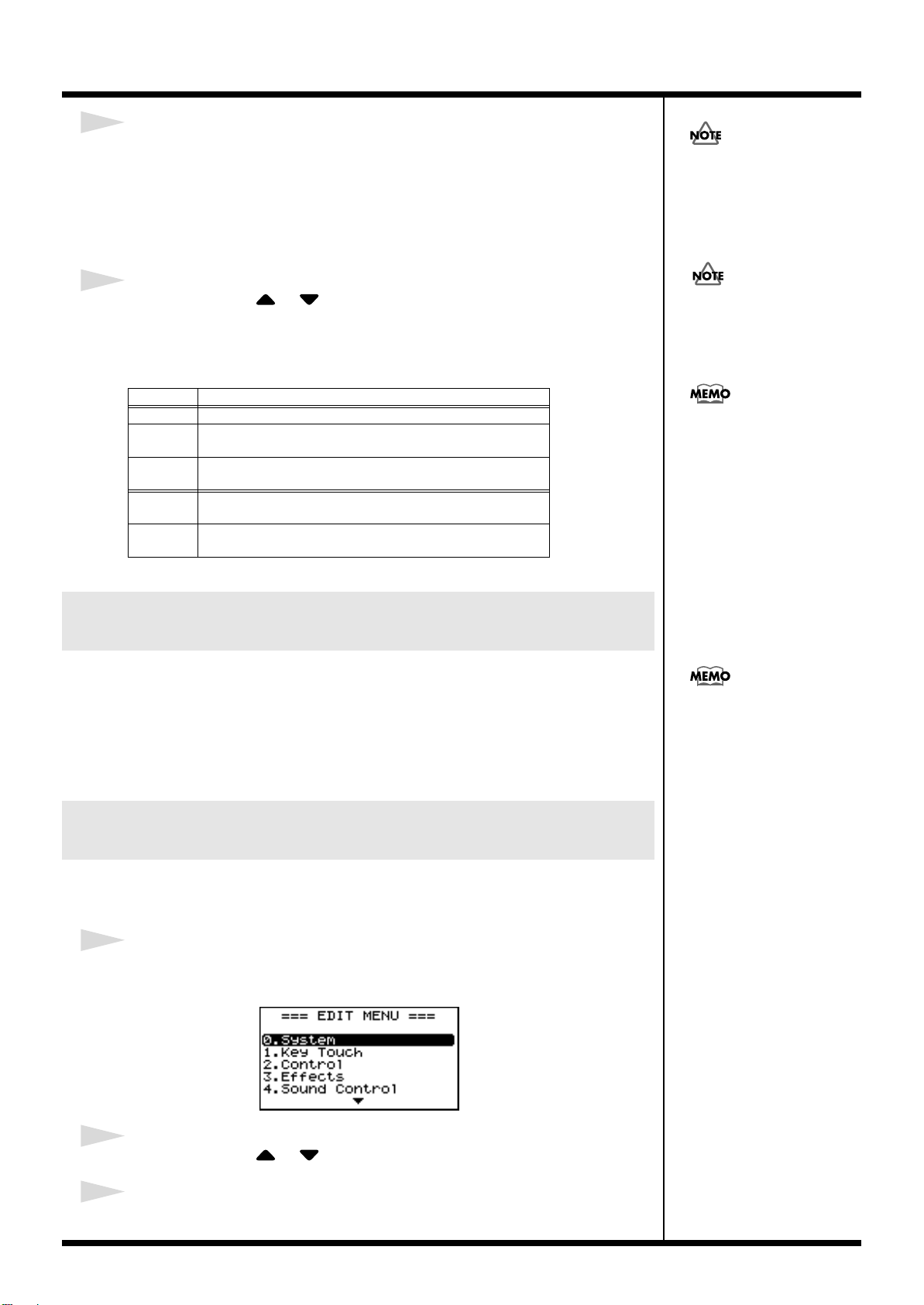
Using the Convenient Functions in Performances
4
When the ZONE LEVEL sliders are moved, the harmonic bars move in
the display, and the tone changes.
By pressing the ZONE SWITCH buttons on and off, you can adjust the sounds for
other Feet.
If the cursor is moved to the value at the bottom of the screen, you can adjust the
sounds for Feet with [DEC] and [INC].
The Percussion is applied only
to the UPPER Tone.
5
Press CURSOR [ ]/[ ] to move the cursor to <Perc> and press
[DEC]/[INC] to change the value.
Perc (Percussion) adds an attack-type sound to the beginning of the note to give the
sound more crispness. The attack sound changes according to the value.
Settings
OFF
2nd Percussion sounds at a pitch one octave above that of the key
3rd Percussion sounds at a pitch an octave and a fifth above that
Slow The percussion’s attenuation time is lengthened. This softens
Fast The percussive sound will decay more quickly. This gives
Changing the Undulation of the Organ Tone (Rotary Effect)
While the Tone Wheel screen is displayed, you can change the undulation rate of the
Rotary effect with the Pitch Bend lever.
The Rotary effect is an effect that recreates the sound of the rotating speakers used
to augment the sound of an organ.
The Rotary effect is set to alternately rotate more rapidly or slowly when the Pitch
Bend lever is moved to the left and right; the direction is not fixed.
Description
No percussion is added.
pressed.
of the key pressed.
the sense of attack.
more of a sense of attack for a sharp sound.
When percussion is on, the 1’
pitch will not be produced
(p. 53).
The settings changed here are
stored to each Tone. Even
when you exit from Tone
Wheel mode, you can press
[ORGAN] to select the Tone
with the changed settings.
This Pitch Bend Lever setting
is effective only in the Tone
Wheel screen.
Changing the ZONE LEVEL Slider Feet Assignments (Harmonic Bar)
You can change the Feet assigned to each of the ZONE LEVEL sliders used in Tone
Wheel mode.
1
Press [EDIT], getting the indicator to light.
The Edit Menu screen appears.
fig.Q2-13g
2
Press CURSOR [ ]/[ ] to select “2.Control.”
3
Press [ENTER] to display the Edit screen.
54
Page 55

4
Press CURSOR [ ]/ [ ] to select “Harmonic Bar.”
fig.Q2-14HBar
Feet Assignments in the Tone Wheel Screen
Using the Convenient Functions in Performances
fig.Q2-15g
8'16' 5 1/3' 2'4' 2 2/3' 1'1 3/5'
1 1/3'
5
Press CURSOR [ ]/[ ]/[ ]/[ ] to move the cursor to the
parameter for changing the Feet.
“LED ON” and “LED OFF” in the screen indicate whether ZONE SWITCH is
switched on or off.
Parameter
UP1
UP2
LW1
LW2
Value
16’, 5-1/3’, 8’, 4’, 2-2/3, 2’, 1-3/5’, 1-1/3’, 1’
6
Press [INC]/[DEC] to select the Feet.
7
When you have finished making the settings, press [EDIT],
extinguishing its indicator.
You are returned to the Tone screen.
Disabling the Button (Panel Lock)
Once Panel Lock is engaged, all buttons (except for the VOLUME slider,
CONTRAST knob, Pitch Bend/Modulation lever, Pedal, ONE TOUCH [PIANO],
ONE TOUCH [E.PIANO], and [EXIT]) will not function. This prevents settings from
being changed inadvertently on stage or in other such situations.
1
While holding down [EDIT], press [ENTER].
Following display will appear.
2
Press ONE TOUCH [PIANO] or [EXIT] to cancel Panel Lock.
55
Page 56

Using the Convenient Functions in Performances
Selecting Stored Settings ([SETUP])
The RD-700SX’s INTERNAL ZONE (p. 28) and EXTERNAL ZONE (p. 28) tone
settings, effect settings, and other such settings are collectively referred to as a
“Setup.”
Once you’ve stored your preferred settings, and settings for the songs to be
performed as a Setup, you can then switch whole groups of settings during a
performance just by switching Setups.
You can store up to 100 different Setups.
The RD-700SX is shipped from the factory with recommended Setups already
prepared.
You can also register the Setups you like and use frequently to the TONE SELECT
buttons. These registered Setups are called the “Favorite Setups.”
This function allows you to select Setups more quickly.
Now try actually calling up a Setup.
fig.Q2-16p
The current settings are erased
when a Setup is called up. Be
sure to save any Setup you
would like to keep first before
calling up another Setup (p.
58).
2 1
1
Press [SETUP], getting the indicator to light.
At this time, turn [NUM LOCK] off.
The Setup screen, shown below, appears in the display.
fig.Q2-17g
2
Press [F2 (BANK CHANGE)] to select a bank.
When you press [F1], a list of the Setups registered to the buttons for the selected
bank is displayed.
Hold down [F1] and press CURSOR [ ]/[ ] to switch the screens.
fig.Q2-17g
3
There are four banks, A, B, C,
and D. Each time you press
[F2], the bank is switched in
the following sequence: A → B
→ C → D → A →...
56
3
Press one of the TONE SELECT buttons to select a Setup.
4
Try playing the keyboard.
The settings are switched to those of the Setup that has been called up.
Page 57

Using the Convenient Functions in Performances
b
Selecting Setups Other Than the Favorite Setups
1. Press [SETUP], getting the indicator to light.
2. Press [INC]/[DEC] or TONE SELECT buttons to select the Setup to be
called up.
After [INC]/[DEC] is pressed, the following screen appears; the Setup screen
then reappears after a few moments.
The screen does not change when the TONE SELECT buttons are used to input
Setup numbers. Press [ENTER] afterwards to set the number.
fig.Q2-18g
When the Tone screen is displayed, the [SETUP] indicator lights and the Setup
screen appears when CURSOR [ ] is pressed.
From the Setup screen, you can get back to the Tone screen by pressing CURSOR
[ ].
However, the Tone Wheel screen is displayed if “TW-Organ 1–10” is selected for any
Part in the Tone screen.
Refer to “Simulating the Creation of Organ Tones (Tone Wheel Mode)” (p. 53).
Setups indicated by a “RHY:”
efore the name let you enjoy
performing with a session-like
feel while playing a Rhythm.
Be sure to check it out.
Registering the Setups You Like (Favorite Setups)
You can also register the Setups you like and use frequently to the TONE SELECT
buttons. This function allows you to select Setups more quickly.
You can register a total of 40 setups, ten tones in each of the four banks, to the
Favorite Setups.
Settings registered in the RD-
1
Press [SETUP] to call up the Setup you want to register.
Make sure [NUM LOCK] is off at this time.
2
Press [F2] to select the bank to which you want to register the Setup.
3
Hold down [F1] and press the TONE SELECT button for the
registration destination.
The Setup is registered to the button that is pressed.
700SX are not deleted even
when the power is turned off.
57
Page 58

Using the Convenient Functions in Performances
New Setup Name
Destination
Storing Settings to Setups ([WRITE])
If you want to use the changed content as a new Setup, use the following procedure
to save the settings to a Setup.
You can also change the name of a Setup.
You can store 100 Setups on the RD-700SX.
fig.Q2-19p
1
Press [WRITE], getting the indicator to light.
The Setup screen appears.
fig.Q2-20ge
12 4,76 3 4,78,9
2
Press CURSOR [ ]/[ ] to move the cursor to the positions where
the characters are to be input.
3
Press [INC]/[DEC] to enter the characters.
The following characters are available.
space, ! " # $ % & ' ( ) * + , - . / 0–9, : ; < = > ? @ A–Z, [ \ ] ^ _ ` a–z, { | } ~
When [F2] is pressed, a single-character blank space is inserted; pressing [F1] deletes
one character.
4
Repeat steps 2–3 to input the name.
5
Press CURSOR [ ] to move the cursor to the destination Setup
name.
6
Select the save-destination Setup, either by pressing [INC]/[DEC].
When using the TONE SELECT buttons to input Setup numbers, press [ENTER]
afterwards to set the number.
fig.Q2-22g
You can use the TONE
SELECT buttons to directly
specify and enter characters.
The file that the file name
starts from “. (dot)” cannot be
written.
Pressing CURSOR [ ],
even while inputting the name,
moves the cursor to the savedestination Setup number.
58
Page 59

Using the Convenient Functions in Performances
Settings Not Saved in a Setup
The following settings cannot be saved to a Setup.
• Song Number
• ONE TOUCH [PIANO] and [E.PIANO] Settings (p. 73)
• System Settings (p. 79)
• Sound Control Settings (p. 88)
• V-Link Settings (p. 97)
• Rec Setting (p. 101)
Pressing [F1 (WRITE)] in the Edit screen saves the System, Sound Control, and V-
Link settings.
7
When you have finished determining the save destination and the
name for the new Setup, press [ENTER] or [F1].
The [ENTER] indicator is flashing, and the confirmation message appears.
fig.Q2-23g
If you do not want to save the Setup, press [EXIT] or [WRITE].
The operation is cancelled, and you are returned to the Tone screen.
8
When [ENTER] is pressed, saving of the Setup begins.
When you have finished saving the Setup, the [WRITE] indicator goes out and
you are returned to the Tone screen.
Never switch off the power
while “Writing...” appears in
the display. Doing so may
damage the internal
memory, making it
impossible to use this
instrument.
Setup <000> (PIANO SETUP)
When you press the ONE TOUCH [PIANO] or [E.PIANO], and then press CURSOR
[ ] to bring up the Setup screen, SETUP<000> is displayed.
fig.Q2-24g
This SETUP<000> is the Setup containing the stored settings for ONE TOUCH
[PIANO] or [E.PIANO]; the contents cannot be overwritten by pressing the [WRITE]
as with other Setups.
When saving content changed from the ONE TOUCH [PIANO] or [E.PIANO]
settings, write the settings to SETUP<001> or later.
59
Page 60

Using the RD-700SX As a Master
“Connecting the RD-700SX
to External Equipment” (p.
21)
Keyboard
By connecting an external MIDI device to the MIDI OUT connector on the RD700SX’s rear panel, you can then control the external MIDI device with the RD-700SX.
Normally, the RD-700SX transmits Note messages from the MIDI OUT connector,
but when [EXTERNAL/INTERNAL] is on, you can control not only Note messages,
but a variety of other external MIDI device settings as well.
You can control internal and external sound generators independently.
Pressing [EXTERNAL/INTERNAL] so the button’s indicator is lit enables the RD700SX to control external MIDI sound modules. You use the [EXTERNAL/
INTERNAL] to switch between control of the INTERNAL zone and control of the
EXTERNAL zone.
You can also make detailed settings for MIDI messages transmitted to external
sound modules.
What’s MIDI?
MIDI (Musical Instrument Digital Interface) is a standard specification that allows
musical data to be exchanged between electronic musical instruments and
computers. By using a MIDI cable to connect devices that have MIDI connectors, you
can create an ensemble in which a single MIDI keyboard can play multiple
instruments, or change settings automatically as the song progresses.
About MIDI Connectors
The RD-700SX has the following three types of MIDI connector. Their functions
differ as described below.
fig.Q3-01
MIDI IN Connector
Performance messages from an external MIDI device are received here. These
incoming messages may instruct the RD-700SX to play sounds or switch tones.
MIDI OUT Connector
MIDI messages are transmitted from this connector to external MIDI devices. The
RD-700SX’s MIDI OUT connector is used for sending the performance data of the
keyboard controller section as well as data used for saving various settings and
patterns (Bulk Dump
MIDI THRU Connector
MIDI messages received at MIDI IN connectors are re-transmitted without change
from this connector to an external MIDI device. Use this in situations such as when
you use multiple MIDI devices simultaneously.
→
p. 99).
Connecting to External MIDI Sound Generators
Messages received via the USB
connector are not transmitted
from the MIDI THRU
connector.
fig.Q3-02
V-LINK-compatible
video equipment.
60
MIDI sound module etc.
MIDI IN
MIDI OUT
USB IN
USB OUT
Computer
RD-700SX
Use a USB Cable no longer
than 3 meters.
Page 61

Using the RD-700SX As a Master Keyboard
When Rec Mode is set to ON in
the Utility Rec Setting in Edit
mode, the EXTERNAL screen
as shown to the left is not
displayed. Set Rec Mode to
OFF when setting the MIDI
Transmit channel (p. 101).
Selecting the MIDI Connector to Use for Output (MIDI OUT Port)
The RD-700SX is equipped with two MIDI connectors and one USB connector.
You can select which MIDI OUT connector or USB connector is used for outputting
the signals for each individual zone.
fig.Q3-04p
1
1
Press [EXTERNAL/INTERNAL], getting the indicator to light.
The EXTERNAL screen appears.
If “OUT” doesn’t appear on screen, press CURSOR [ ] several times to display the
following screen.
fig.Q3-05g
2
Press CURSOR [ ]/[ ]/[ ]/[ ] to move the cursor, then press
[INC]/[DEC] to set the connector from which the MIDI messages of
each zone are to be output.
Part
UP1 (UPPER1)
UP2 (UPPER2)
LW1 (LOWER1)
LW1 (LOWER2)
Parameter Settings Description
OUT
(MIDI OUT Port)
ALL,
1 (MIDI OUT 1),
2 (MIDI OUT 2),
USB
The RD-700SX’s performance data is
transmitted from the
selected connector.
2
61
Page 62

Using the RD-700SX As a Master Keyboard
When Rec Mode is set to ON in
the Utility Rec Setting in Edit
mode, the EXTERNAL screen
as shown to the left is not
displayed. Set Rec Mode to
OFF when setting the MIDI
Transmit channel (p. 101).
MIDI Send Channel Settings
When you have finished connecting the external MIDI device, match the keyboard’s
Transmit channel and the Receive channel for each of the external MIDI sound
generator’s Parts. Sounds is produced when the MIDI channels for the sending
device (the RD-700SX) and the receiving device (the external MIDI sound generator)
are set to the same MIDI channel.
fig.Q3-03p
1
1
Press [EXTERNAL/INTERNAL], getting the indicator to light.
The EXTERNAL screen appears.
If “Ch” doesn’t appear on screen, press CURSOR [ ] several times to display the
following screen.
fig.Q3-03g
2
Press CURSOR [ ]/[ ]/[ ]/[ ] to move the cursor, then press
[INC]/[DEC] to set the Transmit channel (Ch) for each part.
Part
UP1 (UPPER1)
UP2 (UPPER2)
LW1 (LOWER1)
LW1 (LOWER2)
Parameter Settings Description
Ch
(MIDI OUT
Channel)
1–16 RD-700SX perfor-
mance data is sent
over a selected channel.
2
For instructions on setting each
of the external MIDI sound
generator’s Part’s Receive
channel, refer to the owner’s
manual for each device.
Part names for Parts in which
ZONE SWITCH is set to OFF
appear in the display in
lowercase letters, such as
“up1,” “up2,” “lw1,” and
MIDI messages for
“rw2.”
Parts with the ZONE
SWITCH set to OFF are not
transmitted.
62
Page 63

Using the RD-700SX As a Master Keyboard
Selecting Sounds on an External MIDI Device
To switch the tones of an external MIDI device, the program number and the MSB/
LSB of the Bank Select message are entered as numerical values on the RD-700SX.
fig.Q3-06p
1
1
Press [EXTERNAL/INTERNAL], getting the indicator to light.
The EXTERNAL screen appears.
If “MSB” doesn’t appear on screen, press CURSOR [ ] several times to display the
following screen.
fig.Q3-07g
Parameter
OUT (MIDI OUT Port)
Ch (MIDI Channel) --- 1–16
MSB (Bank Select MSB) CC 00 0–127, --- (OFF)
LSB (Bank Select LSB) CC 32 0–127, --- (OFF)
PC (Program Change) Program Change 0–127, --- (OFF)
Tx Settings
--- ALL, 1, 2, USB
2
Press CURSOR [ ]/[ ]/[ ]/[ ] to move the cursor, then press
[INC]/[DEC] to set the MSB, LSB, and PC for each part.
Pressing [INC] and [DEC] simultaneously switches the settings value to “--- (OFF).”
When this setting is “--- (OFF),” bank select messages will not be transmitted.
2
When Rec Mode is set to ON in
the Utility Rec Setting in Edit
mode, the EXTERNAL screen
as shown to the left is not
displayed. Set Rec Mode to
OFF when setting the MIDI
Transmit channel (p. 101).
If the external MIDI sound
generator transmits a Program
number or a Bank number for
which no Tone has been
assigned, an alternate Tone
may be selected, or in some
cases, there may be no sound
played. If you do not want to
transmit the Program number
or Bank Select, use the
procedure described left to set
the PC/MSB/LSB to “--(OFF).”
63
Page 64

Using the RD-700SX As a Master Keyboard
“Adjust the Volume Level for
Individual Zones (ZONE
SWITCH/ZONE LEVEL
Slider)” (p. 41)
.
Adjusting the Volume of Each Zone (EXTERNAL Zone)
fig.Q3-08pe
ZONE LEVEL Slider
ZONE SWITCH
When the [EXTERNAL/INTERNAL] indicator is on, you can use the ZONE
SWITCH and ZONE LEVEL sliders to control the EXTERNAL Zone in the same way
as with the INTERNAL Zone (p. 28).
[EXTERNAL/INTERNAL] ON (lit)
ZONE SWITCH
This setting determines whether or not MIDI messages, including the information
for Note On in the EXTERNAL zone, are to be transmitted from MIDI OUT when the
[EXTERNAL/INTERNAL] indicator is lit.
When the ZONE SWITCH indicator for a part is lit (on), MIDI messages are
transmitted from MIDI OUT when the keys for that part are played.
When the ZONE SWITCH indicator for a part is not lighted (off), MIDI messages are
not transmitted from MIDI OUT even when the keys for that part are played.
ZONE SWITCH will turn on or off each time you press it.
ZONE LEVEL Slider
When the [EXTERNAL/INTERNAL] indicator is on, ZONE LEVEL sliders adjust
the volume level of each of the EXTERNAL Zone.
64
Page 65

Using the RD-700SX As a Master Keyboard
Detailed Settings for Transmitted Parts (EXTERNAL)
After pressing [EXTERNAL/INTERNAL], you can then set the
following parameters affecting EXTERNAL Zone.
fig.Q3-09g
How to Make Settings
1.
Press [EXTERNAL/INTERNAL], getting the indicator to light.
The RD-700SX is set to control the external MIDI devices.
When Rec Mode is set to ON in the Utility Rec Setting in Edit
mode, the EXTERNAL screen as shown to the left is not
displayed. Set Rec Mode to OFF when setting the MIDI
Transmit channel (p. 101).
2.
Press CURSOR [ ]/[ ]/[ ]/[ ] to move the cursor
to the parameter to be set.
You can get the cursor to move more rapidly by holding down
the CURSOR button that points in the direction you want the
cursor to move while you also press the CURSOR button that
points in the opposite direction.
3.
Press [INC]/[DEC] to set the value.
Pressing [INC] and [DEC] simultaneously sets the value to “--(OFF).”
Adjusting the Volume and Pan (Volume/Pan)
Sets the volume and the panning (localizes sound image) for each of
the Tones.
The Volume setting is mainly used when multiple tones are playing
to obtain the desired balance in volume between each part.
The Pan setting positions the sound image of each part when the
output is in stereo. With an increase in the value for L, more of the
sound will be heard as coming from the left side. Similarly, more of
the sound will originate at the right if the value of R is increased.
When set to 0, the sound is heard as coming from the center.
Parameter
VOL (Volume)
PAN (Pan) CC10 L64–0–63R, --- (OFF)
TX CC# Value
CC07 --- (OFF), 0–127
Setting the Amount of Reverb and Chorus (Reverb/Chorus)
This sets the depth of the reverb and chorus effects.
Parameter
REV (Reverb)
CHO (Chorus) CC93
TX CC# Value
CC91 --- (OFF), 0-127
65
Page 66

Using the RD-700SX As a Master Keyboard
Playing Sound Monophonically (Mono/Poly)
Specifies whether the tone will play polyphonically (POLY) or
monophonically (MONO).
The MONO setting is effective when playing a solo instrument tone
such as sax or flute.
Parameter
M/P (Mono/Poly)
Value
--- (OFF), M (MONO, CC126),
P (POLY, CC127)
Setting the Transposition for Each Individual Zone (Transpose)
You can perform with each zone transposed to a different pitch.
When multiple zones are set to on
by setting the two Tones to different octaves. Also, if the Keyboard
Mode is set to Split and you are playing a bass Tone in the lower
Part, you can use the Transpose function to play the bass at a lower
pitch.
Parameter
TRA (Transpose)
, you can create a richer sound
Value
-48 – 0 –+48
Setting the Key Range (Key Range Lower/Upper)
Set the keyboard range in which each Zone will sound.
This can be used to make notes in different areas of the keyboard
play different Tones.
Specify the lower limit (LWR) and upper limit (UPR) of the key
range being set.
You can also set this by pressing a specific key and then pressing
[ENTER].
Parameter
LWR (Key Range Lower)
UPR (Key Range Upper)
This is effective only when [SPLIT] is on (p. 38) in the key range
settings.
“FUL” is displayed when [SPLIT] is set to OFF. In this case,
[SPLIT] is automatically switched on when the value is changed
to something other than “FUL” with [INC]/[DEC].
You cannot set the key range’s lower limit higher than the
upper limit, nor can you set the upper limit below the lower
limit.
You can use ZONE SWITCH for each individual zone to select
whether or not MIDI Note messages for that zone are to be
transmitted (p. 64).
Value
A0–C8
Changing the Range That Plays in Response to the Velocity (Velocity Range Lower/Upper)
This specifies the lower limit (LWR) and upper limit (UPR) of the
range in which the tone is played according to how strongly the keys
are played (velocity). Make this setting when you want the tone to
change depending on the key velocity.
Parameter
VRL (Velocity Range Lower)
VRU (Velocity Range Upper)
If you set the minimum velocity to a value above the upper
limit, or set the maximum velocity to a value that is below the
lower limit, the setting for the other limit is changed to the same
value.
Value
1–127
Changing Tone Elements (ATK/DCY/REL/COF/RES)
You can make changes in tones by adjusting the settings of the
following four elements.
ATK (Attack Time Offset):
The time it takes after the key is pressed for a sound to reach full
volume.
DCY (Decay Time Offset):
The time it is to take following the attack for the volume to decrease.
REL (Release Time Offset):
The time it takes after the key is released for a sound to become
inaudible.
COF (Cutoff Offset):
Adjusts how much the filter is opened.
RES (Resonance Offset):
This boosts the portions in the region around the cutoff frequency,
lending a particular quality to the sound. Excessively high settings
can produce oscillation, causing the sound to distort.
Parameter
ATK
DCY CC75 The time it takes for the vol-
REL CC73 Higher values produce
COF CC74 Higher values brighten the
RES CC71 Higher value makes the
TX CC# Value Description
CC73 --- (OFF),
-64–+63
Higher values produce a
milder attack; lower values
produce a sharper attack.
ume to fall increases as the
value is raised; lowering the
value decreases the decay
time.
longer decay; set lower values for a clear-cut sound.
sound; lower values make
the sound seem darker.
special quality of the sound
stronger; lower value reduce these characteristics.
66
Page 67

Using the RD-700SX As a Master Keyboard
Smoothly Changing the Pitch (Portamento)
Portamento is a function that causes the pitch to change smoothly
from one note to the next note played.
The Portamento Time setting determines the time for the change in
pitch when the portamento effect is applied to the sound. Higher
settings will cause the pitch change to the next note to take more
time.
Parameter
POR (Portamento Switch)
P.T (Portamento Time) CC5 ---, 0–127
TX CC# Value
CC65 ---, OFF, ON
Setting the Change in Volume
According to the Force Used to
Play the Keyboard
(Velocity Sensitivity/Max)
Set the change in volume that occurs in response to the force used to
play the keyboard (velocity) and the maximum value of the change.
Parameter
SNS
(Velocity
Sensitivity)
MAX
(Velocity Max)
Value Description
-63–+63 This setting determines how the volume changes in response to the velocity.
The volume is increased as the keyboard is played with greater force
when a positive Value is used; when
a negative value is selected, the volume decreases as the keys are
played with greater force. If this is
set to “0,” the volume will not be affected by the strength of your playing on the keyboard.
1–127 Maximum velocity value for the
corresponding key.
Lowering this value will produce
softer notes even if you play the keyboard strongly.
Setting the Range for the Change in Pitch with the Bender (Bend Range)
This sets the amount of pitch change that will occur when you move
the Pitch Bend lever (4 octaves).
Parameter
B.R (Bend Range)
RPN Value
00H/00H --- (OFF), 0–48
(semitone)
Setting the Amount of Modulation Applied (Modulation Depth)
This sets the depth of the effect when the Modulation lever is tilted.
Parameter
M.D (Modulation Depth)
RPN Value
00H/05H --- (OFF), 0–127st
Turning Each Controller On and Off
These settings determine whether the external MIDI device is
controlled (ON), or not (OFF) by the pedals connected to each
PEDAL jack, the slider, the Modulation lever, and the Bender.
Parameter
Dp
F1 Pedal connected to the FC1 jack
F2 Pedal connected to the FC2 jack
PB Pitch Bender
Md Modulation Lever
UP1 Control Slider (UP1)
UP2 Control Slider (UP2)
LW1 Control Slider (LW1)
LW2 Control Slider (LW2)
Description Value
Damper pedal ON, OFF
Changing the Pitch (Coarse Tune/Fine Tune)
This makes settings related to the pitch of each Part.
Parameter
C.T
(Coarse Tune)
F.T
(Fine Tune)
1 cent = 1/100 semitone
RPN Description Value
00H/
02H
00H/
02H
Sets the sound’s
pitch in semitone
units.
Sets the sound’s
pitch in units of
one cent.
--- (OFF),
-48– +48
(+/- 4 octaves)
--- (OFF),
-50– +50
(+/- 50 cents),
Transmitting the Control Change (USER CC/USER CC Value)
You can make two types of settings here, the Control Change
message to be transmitted and the value for the Control Change.
Parameter
CC1 (User CC1)
Value (User CC1 Value)
CC2 (User CC2)
Value (User CC2 Value)
Value
OFF, 0–127
67
Page 68

Making Detailed Settings for Tones
Making Zone Settings (Zone Info)
The sixteen Parts played by the RD-700SX’s internal sound generator
are referred to as “Internal Parts.”
Of the sixteen Internal Parts, you can select four of them to function
as the four Parts (UPPER1, UPPER2, LOWER1, and LOWER2) which
can be freely controlled with the RD-700SX’s buttons and keyboard.
These four Parts are collectively known as the “Zone.”
You can perform operations like Split with the INTERNAL Zone
very simply using the RD-700SX’s keyboard, and you can make
more detailed settings for the Zone as well.
Depending on the tone selected, there may be parameters that
cannot be altered.
How to Make Settings
1.
In the Tone screen, press [F2 (Zone Info)].
The [F2] is lit, and the Zone Info screen appears.
fig.04-01g
Selecting the Tone
When the zone to be set is selected, the name of the assigned tone
appears.
You can select tone using the TONE SELECT buttons.
Parameter
Tone
Value
Refer to
“Tone List”
(p. 146)
Setting the Volume and Pan (Volume/Pan)
Sets the volume and the panning (localizes sound image) for each of
the Zones.
The Volume setting is mainly used when multiple tones are playing
to obtain the desired balance in volume between each zone.
The Pan setting localizes the sound image of each zone when the
output is in stereo. With an increase in the value for L, more of the
sound will be heard as coming from the left side. Similarly, more of
the sound will originate at the right if the value of R is increased.
When set to 0, the sound is heard as coming from the center.
Parameter
VOL (Volume)
PAN L64–0–R63
Value
0–127
The names of zones that have Zone SW set to OFF are shown in
lowercase letters.
2.
Press CURSOR [ ]/[ ] to switch screens.
3.
Press CURSOR [ ]/[ ]/[ ]/[ ] to move the
cursor to the parameter to be set.
fig.04-02g
4.
Press [INC]/[DEC] to set the value.
Pressing [INC] and [DEC] simultaneously sets
to the standard default value
5.
When you finish making settings, press [F2],
.
that parameter
extinguishing its indicator.
You are returned to the Tone screen.
Setting the Zone to Which Multieffects Are Applied
(MFX1/MFX2 Source)
This setting determines the zone to which multi-effects are applied.
Parameter Value
FX1 (MFX1 Source)
FX2 (MFX2 Source)
Multi-effects can be applied to only one zone. Once one zone
has been switched on, the same multi-effect is switched off in
the other zones.
You can apply either MFX1 or MFX2 (not both) to a zone. If
both MFX1 and MFX2 are switched on for the same zone, MFX2
alone will be the one that is actually applied.
ON, OFF
68
Page 69

Making Detailed Settings for Tones
Setting the Transposition for Each Individual Zone (Transpose)
You can perform with each Zone transposed to a different pitch.
When multiple tones are playing, you can create a richer sound by
setting the two Tones to different octaves. Also, if the Keyboard
Mode is set to Split and you are playing a bass Tone in the lower
Zone, you can use the Transpose function to play the bass at a lower
pitch.
Parameter
TRA (Transpose)
You can also set the same degree of transposition for all parts
with [TRANSPOSE]. For details, refer to
of the Keyboard ([TRANSPOSE])”
Value
-48–0–+48
“Transposing the Key
(p. 42).
Setting the Key Range for Each Zone (Key Range)
When [SPLIT] is pressed in normal performance conditions, the key
range is divided at the Split Point, and you can play with two
different tones on one keyboard.
Using Key Range allows you to make even more detailed key range
settings.
This sets the lower and upper limit of the key range in each part.
After moving the cursor to the parameter to be set, you can make the
setting by pressing the designated key and [ENTER].
Parameter
LWR (Key Range Lower)
UPR (Key Range Upper)
This is effective only when [SPLIT] is on (p. 38) in the key range
settings.
“FUL” is displayed when [SPLIT] is set to OFF. In this case,
[SPLIT] is automatically switched on when the value is changed
to something other than “FUL” with [INC]/[DEC].
Value
A0–C8
Setting the Change in Volume
According to the Force Used to
Play the Keyboard
(Velocity Range/Sens/Max)
This setting determines how the volume changes in response to the
force used to play the keyboard (velocity) and the maximum value of
the change.
This setting is disregarded with certain tones.
Parameter Value Description
VRL (Velocity
Range Lower)
VRU (Velocity
Range Upper)
Sns
(Velocity
Sensitivity)
Max
(Velocity Max)
1–127 This specifies the lower limit
(VLW) and upper limit (VUP) of
1–127
-63–+63 This setting determines how the
1–127 Maximum velocity value for the
the range in which the tone is
played according to the velocity.
Make this setting when you want
the tone to change depending on
the key velocity.
volume changes in response to the
velocity.
The volume is increased as the
keyboard is played with greater
force when a positive Value is
used; when a negative value is
selected, the volume decreases as
the keys are played with greater
force. If this is set to “0,” the
volume will not be affected by the
strength of your playing on the
keyboard.
corresponding key.
Lowering this value will produce
softer notes even if you play the
keyboard strongly.
Assigning Internal Parts to INTERNAL Zone (Part Assign)
This determines which internal Parts are assigned to the INTERNAL
Zone.
You cannot set the key range’s lower limit higher than the
upper limit, nor can you set the upper limit below the lower
limit.
When the split point (p. 39) is changed, the Key Range value
also changes.
Parameter
P.A (Part Assign)
Value
1–16
69
Page 70

Making Detailed Settings for Tones
Turning the Controllers in Each Zone On and Off
These settings determine whether the pedals connected to each
PEDAL jack (DaMPER, FC1, FC2), the Modulation lever, the Bender,
and the Slides are used to control the Parts (ON), or not (OFF).
Parameter
Dp
F1 Pedal connected to the FC1 jack
F2 Pedal connected to the FC2 jack
PB Pitch Bender
Md Modulation Lever
UP1 Control Slider (UP1)
UP2 Control Slider (UP2)
LW1 Control Slider (LW1)
LW2 Control Slider (LW2)
Description Value
Damper pedal ON, OFF
Making Tone Settings (Tone Info)
You can make more detailed settings to the tones assigned to each of
the Internal parts.
In certain selected Tones, there may be parameters that cannot
be changed.
How to Make Settings
1.
In the Tone screen, press [F1(Tone Info)].
The [F1] is lit, and the Tone Info screen appears.
fig.04-03g
2.
Press CURSOR [ ]/[ ] to switch screens, and
press CURSOR [ ]/[ ] to move the cursor to
the parameter to be set.
fig.04-04g
3.
Press [INC]/[DEC] to set the value.
4.
When you finish making settings, press [F1],
extinguishing its indicator.
You are returned to the Tone screen.
The following parameters cannot be changed when the selected
tone is used as the Virtual Tonewheel tone.
• Mono/Poly
• Coarse Tune
• Fine Tune
• Portamento Switch
• Portamento Time
• Attack Time
• Release Time
• Cutoff
• Resonance
• Decay Time
70
Page 71

Making Detailed Settings for Tones
Selecting the Part and the Tone to Be Set (Part, Tone)
Choose the Part and the Tone for which you want to make settings.
Parameter
<Part>
Tone When the part to be set is selected, the name of the
Value
1–16
Parts assigned to the INTERNAL Zone are
indicated by a marker (UPPER1) appearing after
the part name.
assigned tone appears.
You can select tone using the TONE SELECT
buttons.
Setting the Reverb/Chorus Depth (Reverb/Chorus Amount)
This sets the depth of the reverb and chorus effects.
When this value is set to “0,” no reverb or chorus effect is
applied when the REVERB [DEPTH] or CHORUS [DEPTH]
knob is turned.
Parameter
Reverb Amount
Chorus Amount
Value
0–127
Playing Sound Monophonically (Mono/Poly)
Specifies whether the tone will play polyphonically (POLY) or
monophonically (MONO).
The MONO setting is effective when playing a solo instrument tone
such as sax or flute.
Additionally, when this is set to “MONO LEGATO,” you can have
monophonic performances played legato. Legato is a playing style in
which the spaces between notes are smoothed, creating a flowing
feel with no borders between the notes. This creates a smooth
transition between notes, which is effective when you wish to
simulate the hammering-on and pulling-off techniques used by a
guitarist.
Parameter
Mono/Poly
Value Description
MONO Only the last-played note
will sound.
POLY Two or more notes can be
played simultaneously.
MONO LEGATO Legato is applied to
monophonic
performances.
Changing the Pitch (Coarse Tune/Fine Tune)
This sets the pitch of the tone.
The manner in which the effect is applied will differ depending
on the settings for MFX Source (p. 86) and MFX1 Dest (p. 87).
• When MFX1 Dest is set to ALL PART
The Reverb/Chorus Amount setting for the part selected for
MFX Source applies to all parts. However, when the MFX
Source is set to FIXED, the Reverb/Chorus Amount setting for
UPPER 1 applies to all parts.
• When MFX1 Dest is set to SAME MFX
The Reverb/Chorus Amount setting for the part selected for
MFX Source applies to parts assigned the same MFX Type as
the part selected for MFX Source.
Changing the Effect Applied to the Tone (MFX Type)
This sets the multi-effect applied to the tone.
The MFX selected here may not be applied with certain MFX
Source and MFX Dest settings. For details, refer to
Source”
Parameter
MFX TYPE
(p. 86),
“MFX Dest”
Value
Refer to
(p. 87).
“Effect/Parameter List”
“MFX
(p. 112).
Parameter
Coarse Tune
Fine Tune -50–+50
1 cent = 1/100 semitone
With some Tones, there may be ranges in which the pitch does
not change as intended.
Value Description
-48–+48
(+/- 4 octaves)
(+/- 50 cents)
Sets the sound’s pitch in
semitone units.
Sets the sound’s pitch in
units of one cent.
Creating Smooth Pitch Changes (Portamento Switch/Time)
Portamento is a function that causes the pitch to change smoothly
from one note to the next note played.
With the Mono/Poly parameter set to MONO, portamento is
especially effective when simulating playing techniques such as a
violin glissandos.
The Portamento Time setting determines the time for the change in
pitch when the portamento effect is applied to the sound. Higher
settings will cause the pitch change to the next note to take more
time.
Parameter
Portamento Sw
Portamento Time 0–127
Value
ON, OFF
71
Page 72

Making Detailed Settings for Tones
Changing Tone Elements (Attack Time/Release Time/Cutoff/ Resonance/Decay Time)
You can make changes in tones by adjusting the settings of the
following four elements.
Attack Time Offset:
The time it takes after the key is pressed for a sound to reach full
volume.
Release Time Offset:
The time it takes after the key is released for a sound to become
inaudible.
Cutoff Offset:
Adjusts how much the filter is opened.
Resonance Offset:
Emphasizes the overtones in the region of the cutoff frequency,
adding character to the sound. Excessively high settings can produce
oscillation, causing the sound to distort.
Decay Time Offset:
The time it is to take following the attack for the volume to decrease.
Making abrupt changes in the settings values may cause the
sound to become distorted or overly loud. Carefully monitor
volume levels while making the settings.
Parameter
Attack Time
(Offset)
Release Time
(Offset)
Cutoff
(Offset)
Resonance
(Offset)
Decay Time
(Offset)
With some Tones, the effect does not work as intended.
Value Description
-64–+63 Higher values produce a milder
attack; lower values produce a
sharper attack.
Higher values produce longer
decay; set lower values for a clearcut sound
Higher values brighten the sound;
lower values make the sound
seem darker.
Higher value makes the special
quality of the sound stronger;
lower value reduce these
characteristics.
The time it takes for the volume to
fall increases as the value is raised;
lowering the value decreases the
decay time.
Changing the Bend Range (Bend Range)
This sets the amount of pitch change that will occur when you move
the Pitch Bend lever (2 octaves).
Parameter
Bend Range
Value
0–24 (semitone)
72
Page 73

Making Detailed Settings for the ONE TOUCH Tones
Making Detailed Settings for the Piano Tones (Piano Edit)
You can make more detailed settings to fashion just the Tones you
want using the piano Tone selected by pressing ONE TOUCH
[PIANO] (p. 32).
This function is called “Piano Edit.”
Furthermore, you can save up to two of the changed settings.
The Piano Edit settings and ONE TOUCH [PIANO] Type A or B is
stored in memory.
When ONE TOUCH [PIANO] is pressed, all settings other than
the Piano Edit settings are switched to their status at the time
the RD-700SX’s power was turned on. Store any arrangements
of settings that you want to keep in Setup (p. 58).
Making the settings
1.
Press [F1] in the ONE TOUCH [PIANO] screen to
select the type you want to set.
Pressing [F1] toggles you between Types A and B.
Depending on the piano Tone selected, this setting may not be
available.
Selecting the Piano Sound
This chooses the piano Tone to be selected when ONE TOUCH
[PIANO] is pressed.
There are 20 Tones to choose from.
Changing the Width of the Sound (Stereo Width)
Adjusts the spaciousness of the sound.
Parameter Value Description
Stereo Width CENTER,
L01-01R–
L63-63R
The higher the value set, the wider
the sound is spread out.
Changing the Sound’s Nuance (Nuance)
This changes the Tone’s subtle nuances by altering the phase of the
left and right sounds.
2.
Press [F2 (EDIT)].
A Piano Edit screen will appear.
fig.04-05-1g
fig.04-05-2g
3.
Press CURSOR [ ]/[ ] to switch screens, and
press CURSOR [ ]/[ ] to move the cursor to
the parameter to be set.
Move the cursor to one of the following menus and press
[ENTER], then select the parameter you want to set in the
screen that follows.
1. Key Touch Edit
2. Micro Tune Edit
3. Sym. Resonance
4. Tone Modify
5. Initialize
4.
Press [INC]/[DEC] to set the value.
5.
If you want to save the setting, press [F1 (WRITE)].
The confirmation message appears. Press [F1 (WRITE)] to save
the settings. If you want to cancel, press [EXIT].
Parameter
Nuance
This effect is difficult to hear when headphones are used.
Value
TYPE1, 2, 3
Changing the Sense of Space Surrounding the Sound (Ambience)
Changing the sound’s ambience allows you give your performances
a sound resembling that obtained in a wide open space.
Parameter
Ambience
Value Description
OFF, 1–5 The effect becomes deeper as the
value is increased.
Changing the Amount of Reverb Effect (Reverb Level)
Adjusts the depth of the Reverb effect. This functions the same way
as the REVERB knob, but the setting made here can be called up
simply by pressing ONE TOUCH [PIANO].
Parameter
Reverb Level
Value Description
0–127 The reverb effect becomes
stronger as the value is increased.
6.
When you finish making settings, press [EXIT].
You are returned to the ONE TOUCH [PIANO] screen.
73
Page 74

Making Detailed Settings for the ONE TOUCH Tones
Opening/Closing the Piano Lid (Lid)
Reproduces the way the brightness of a grand piano’s sound is
affected by how much the piano’s lid is opened.
Parameter
Lid
Value Description
1–6 The lid is opened more as the
value is increased, creating a
brighter sound.
Changing the Characteristics of the Mic (Mic Type/Distance)
This changes the sound of the instrument in a manner similar to that
accomplished in recordings of miked acoustic instruments like
pianos, where the sound is changed by using mics with different
characteristics and changing the mic placement. This function is a
virtual reproduction of these phenomena.
Parameter
Mic Type
Distance 0–10 The distance to the microphone
Value Description
OFF No microphone is used.
CONDENSER This is a simulation of a small
condenser mic used for musical
instruments. The mic features a
very bright high end.
DYNAMIC This simulates the type of
dynamic mic used widely for
vocals and instruments.
decreases as the value is raised,
and the distance increases as the
value is lowered.
Adjusting the Resonant Sounds When the Keys are Pressed (String Resonance)
When the keys are pressed on an acoustic piano, the strings for keys
that are already pressed also vibrate sympathetically. The function
used to reproduce is called “String Resonance.”
Parameter Value Description
String Resonance
OFF, 1–5 Increasing the value will
increase the amount of effect.
Making the Midrange Equalizer Settings (EQ SW/EQ Gain/EQ Frequency/EQ Q)
Parameter
EQ Gain -12.0–+12.0 dB Change the amount of
EQ
Frequency
EQ Q 0.5, 1.0, 2.0, 4.0,
Value Description
equalization (gain).
100, 125, 160,
200, 250, 315,
400, 500, 630,
800, 1000, 1250,
1600, 2000,
2500, 3150,
4000Hz
8.0
Set Frequency Point. Changes the
level of the selected frequency
range, with frequency selected
here at the center.
Adjusts the “Q” (bandwidth) of
equalization. The higher the value,
the narrower the range of
frequencies that are affected.
Changing the Key Touch (Key Touch)
You can make advanced settings for the touch used for the keys.
Parameter
Key Touch
This setting is switched automatically according to the value of
Key Touch Offset, which follows.
Changing this setting also changes the Key Touch setting in Edit
Mode (p. 83).
Value Description
SUPER
LIGHT
LIGHT This sets the keyboard to a light
MEDIUM This sets the keyboard to the
HEAVY This sets the keyboard to a heavy
SUPER
HEAVY
An even lighter setting than
LIGHT.
touch. You can achieve fortissimo
(ff) play with a less forceful touch
than usual, so the keyboard feels
lighter. This setting makes it easy
to play, even for children.
standard touch. You can play with
the most natural touch. This is the
closest to the touch of an acoustic
piano.
touch. You have to finger the
keyboard more forcefully than
usual in order to play fortissimo
(ff), so the keyboard touch feels
heavier. Dynamic fingering adds
even more feeling to what you
play.
An even heavier setting than
HEAVY.
This sets the midrange equalization.
Parameter Value Description
EQ SW ON, OFF This determines whether the
following EQ Gain, EQ Frequency,
and EQ Q settings are enabled
(ON), or not (OFF).
74
Page 75

Making Detailed Settings for the ONE TOUCH Tones
Making Fine Adjustments to the Keyboard Touch (Key Touch Offset)
This setting provides even more precise adjustment of the key touch
than available with the Key Touch setting alone.
This allows you to adjust between Key Touch settings values.
Parameter
Key Touch
Offset
When this settings value continues into the positive or negative
direction, the Key Touch’s five-step value is switched
automatically in accordance with that value.
Value Description
-10–+9 The touch sensitivity becomes
heavier as the value increases.
Setting a Constant Volume Level in Response to the Playing Force (Velocity)
This sets the sound to play at a fixed volume, regardless of the
strength used to play the keyboard (the velocity).
Parameter Value Description
Velocity
REAL Volume levels and the way sounds
are played change in response to
the velocity.
1–127 Values for the volume and the way
sounds are played remain
constant.
Changing the Timing of Sounds in Response to the Velocity (Velocity Delay Sens)
This sets the interval from the time the key is played to when the
sound is produced.
As the value is decreased, the timing of the sound is delayed more
when more force is used to play the keys.
As the value is increased, the timing of the sound is delayed more
when less force is used to play the keys.
Parameter
Velo Delay Sens
Value
-63–+63
Changing the Touch Sensitivity According to the Key Range (Velocity Keyfollow Sens)
This setting changes the touch sensitivity according to the key range
being used.
As the value is increased, the touch becomes heavier in the upper
registers, and lighter in the lower keys.
Parameter
Velo Keyfolw Sens
Value
-63–+63
Finely Adjusting the Tuning (Micro Tune)
This procedure allows micro-tuning of each individual key.
Parameter
Type
1.
Select “2. Micro Tune Edit” in Step 3 of the piano edit
settings procedure (p. 73), then press [ENTER].
The Micro Tune Edit screen appears.
fig.04-06g
Pressing [EXIT] returns you to the immediately preceding
screen.
2.
Press CURSOR [ ] to move the cursor to the
“TYPE.”
3.
Press [INC]/[DEC] to select the type.
4.
Press CURSOR [ ] to move the cursor to the
numerical value (Offset).
5.
Press the key to specify it as the one you want to
tune.
6.
Press [INC]/[DEC] to adjust the value.
7.
If you want to save the setting, press [F1 (WRITE)].
The setting is saved to “USER.”
Value
PRST (PRESET), USER, 1–14
Adjusting Resonance when the Damper Pedal is Depressed (Sympathetic Resonance)
You can adjust this resonance when the damper pedal is depressed.
On an acoustic piano, holding down the damper pedal will allow the
remaining strings to resonate in sympathy with the sounds that you
played from the keyboard, adding a rich resonance. This feature
reproduces that resonance sound.
Parameter Value Description
Resonance
Depth
Resonance
Pitch
Resonance
Level
0–10 The volume of the resonance
increases as the value is raised.
Adjusts the amount of the
wavering effect. The wavering
effect increases as the value is
raised.
The volume of the wavering effect
increases as the value is raised.
75
Page 76

Making Detailed Settings for the ONE TOUCH Tones
Changing Sound Characteristics (Tone Modify)
You can make changes in tones by adjusting the settings of the
elements.
Decay Time Offset:
The time it is to take following the attack for the volume to decrease.
Cutoff Offset:
Adjusts how much the filter is opened.
Release Time Offset:
The time it takes after the key is released for a sound to become
inaudible.
Parameter
Decay Time
(Offset)
Cutoff
(Offset)
Release
Time
(Offset)
With certain tones, the effect may be difficult to distinguish.
Value Description
-64–+63 The time it takes for the volume to
fall increases as the value is raised;
lowering the value decreases the
decay.
Higher values brighten the sound;
lower values make the sound seem
darker.
Higher values produce longer decay;
set lower values for a clear-cut
sound.
Making Detailed Settings for the E.Piano Tones (E.Piano Edit)
You can make more detailed settings to fashion just the Tones you
want using the E.piano Tone selected by pressing ONE TOUCH
[E.PIANO] (p. 32).
This function is called “E.Piano Edit.”
The settings made in E.Piano Edit are stored to ONE TOUCH
[E.PIANO].
When ONE TOUCH [E.PIANO] is pressed, all settings other
than the E.Piano Edit settings are switched to their status at the
time the RD-700SX’s power was turned on. Store any
arrangements of settings that you want to keep in Setup (p. 58).
Making the settings
1.
Press [F1] in the ONE TOUCH [E.PIANO] screen to
select the type you want to set.
2.
Press [F2].
fig.04-g07-1
Restore the settings to initial conditions (Initialize)
This restores the One Touch E. Piano settings to their initial
conditions.
1.
In Step 3 of the Piano Edit settings instructions
(p. 73), select “5. Initialize” and press [ENTER].
To cancel the Initialize, press [EXIT].
2.
Press [ENTER].
The confirmation message appears.
3.
Press [ENTER] once again.
The ONE TOUCH [PIANO] tones are initialized.
3.
Press CURSOR [ ]/[ ] to switch screens, and
press CURSOR [ ]/[ ] to move the cursor to
the parameter to be set.
4.
Press [INC]/[DEC] to set the value.
5.
If you want to save the setting, press [F1 (WRITE)].
The confirmation message appears. Press [F1 (WRITE)] to save
the settings. If you want to cancel, press [EXIT].
6.
When you finish making settings, press [EXIT].
You are returned to the ONE TOUCH [E.PIANO] screen.
76
Page 77

Making Detailed Settings for the ONE TOUCH Tones
Selecting the E.Piano Sound
This chooses the piano Tone to be selected when ONE TOUCH
[E.PIANO] is pressed.
There are 21 Tones to choose from.
Selecting the Amp Type(AMP Type)
In the past, the sounds of electric pianos and similar instruments
were always played through some kind of instrument amp.
The function simulates the sonic characteristics of these instrument
amps.
Parameter
AMP Type
Value Description
OFF No amp is used.
EP-AMP This simulates the amp section of a
vintage electric piano featuring a
built-in amp.
GTR-AMP This simulates a multipurpose guitar
amp.
Applying Effects to the Sound (Effect Type/Depth/Rate)
You can use effects that are often used with electric pianos.
Parameter
Effect Type OFF, CHORUS,
Effect Depth 0–127 This sets the amount of effect
Effect Rate 1–200 This sets the rate of the effect's
Value Description
Selecting the type of effects.
TRERMOLO,
AUTO-WAH,
PHASER
applied to the sound.
Increasing the value deepens
the effect, while the effect gets
weaker at lower values.
cycling. Increasing the value
deepens the effect, while the
effect gets weaker at lower
values.
Making the Midrange Equalizer Settings (EQ-SW/EQ Gain/ EQ Frequency/EQ Q)
Parameter
EQ Q 0.5, 1.0, 2.0, 4.0, 8.0 Adjusts the “Q” (bandwidth)
Depending on the piano Tone selected, this setting may not be
available.
Value Description
of equalization. The higher
the value, the narrower the
range of frequencies that are
affected.
Changing Sound Characteristics (Tone Modify)
You can make changes in tones by adjusting the settings of the
elements.
Decay Time Offset:
The time it is to take following the attack for the volume to decrease.
Cutoff Offset:
Adjusts how much the filter is opened.
Resonance Offset:
Emphasizes the overtones in the region of the cutoff frequency,
adding character to the sound. Excessively high settings can produce
oscillation, causing the sound to distort
Release Time Offset:
The time it takes after the key is released for a sound to become
inaudible.
Making abrupt changes in the settings values may cause the
sound to become distorted or overly loud. Carefully monitor
volume levels while making the settings.
Parameter
Decay Time
(Offset)
Cutoff
(Offset)
Resonance
(Offset)
Release Time
(Offset)
Value Description
-64–+63 The time it takes for the volume to fall
increases as the value is raised;
lowering the value decreases the
decay time.
-64–+63 Higher values brighten the sound;
lower values make the sound seem
darker.
-64–+63 Higher value makes the special quality
of the sound stronger; lower value
reduce these characteristics.
-64–+63 Higher values produce longer decay;
set lower values for a clear-cut sound
This sets the midrange equalization.
Parameter Value Description
EQ SW ON, OFF This determines whether the
following EQ-Freq, EQ Gain,
and EQ Q settings are
enabled (ON), or not (OFF).
EQ Gain -12.0–+12.0 dB Change the amount of
equalization (gain).
EQ
Frequency
100, 125, 160, 200,
250, 315, 400, 500,
630, 800, 1000,
1250, 1600, 2000,
2500, 3150, 4000Hz
Set Frequency Point. Changes
the level of the selected
frequency range, with
frequency selected here at the
center.
77
Page 78

Detailed Settings for Each Function ([EDIT])
The process of changing tone parameters to create the tones you like,
and changing the settings for various functions is known as
“editing.”
When [EDIT] is pressed and the indicator is lit, the RD-700SX
switches to “Edit mode.”
You can save edited settings to Setups.
Edited settings are discarded when the RD-700SX’s power is turned
off, so be sure that any settings you want to keep are saved to a
Setup. For details, refer to
(p. 58).
System function (0. System) settings are saved the instant a change is
made in any of the parameter values. Therefore, no changes to the
settings are lost, even when the power is turned off.
“Storing Settings to Setups ([WRITE])”
Parameters That Can Be Set
You can set the following parameters in Edit mode.
0.System
1. Key Touch
2. Control
3. Effects
Master Tune
Master Volume p. 80
EQ Mode p. 80
Pedal Mode p. 80
Tone Remain p. 81
Clock Source p. 81
Clock Out p. 81
SETUP Control Channel p. 81
Device ID p. 81
USB Driver p. 106
Damper Polarity p. 81
FC1 Polarity p. 81
FC2 Polarity p. 81
Display Mode p. 82
Part Mode p. 82
Temperament p. 82
Temperament Key p. 82
Stretch Tune p. 82
Rx GM/GM2 System ON p. 82
Rx GS Reset p. 82
Key Touch
Key Touch Offset p. 83
Velocity p. 84
Velocity Delay Sensitivity p. 84
Velocity Keyfollow Sensitivity p. 84
FC1 Pedal Assign p. 85
FC2 Pedal Assign p. 85
Control Knob Assign p. 85
Slider Assign p. 85
Harmonic Bar p. 54
MFX Structure p. 86
MFX1 Source p. 86
MFX2 Source p. 86
MFX1 Destination p. 87
Type p. 87
MFX Control p. 87
MFX Parameters p. 87
Reverb Type p. 87
Reverb Parameters p. 87
Chorus Type p. 88
Output Select p. 88
Chorus Parameters p. 88
p. 27
p. 83
4. Sound Control
5. File Utility/
USB
6. Part
Parameter
7. Rhythm/
Arpeggio
8. V-Link
9. Utility
Type
Split Frequency L p. 89
Split Frequency H p. 89
Level p. 89
Attack Time p. 89
Release Time p. 89
Threshold p. 89
Ratio p. 89
Save SETUP File
Load SETUP File p. 90
File Delete p. 91
USB Setting p. 104
USB Storage p. 105
Part
Tone p. 92
Receive Channel p. 92
Volume p. 92
Pan p. 92
Voice Reserve p. 92
Part Switch p. 92
MFX Switch p. 92
Rx Bank Select p. 92
Rx Program Change p. 92
Rx Modulation p. 92
Rx Pitch Bend p. 92
Rx Volume p. 92
Rx Hold -1 p. 92
Rx Pan p. 92
Rx Expression p. 92
Rhythm
Rhythm Tempo p. 93
Rhythm Volume p. 93
Rhythm Pattern p. 93
Rhythm Set p. 94
Rhythm Set Change p. 94
Rhythm Accent p. 94
Rhythm/Arpeggio Grid p. 94
Rhythm/Arpeggio Duration p. 94
MIDI Out Port p. 94
MIDI Out Channel p. 94
Arpeggio
Arpeggio Tempo p. 95
Arpeggio Style p. 95
Arpeggio Motif p. 95
Arpeggio Zone p. 96
Arpeggio Key Range p. 96
Arpeggio Velocity p. 96
Rhythm/Arpeggio Grid p. 94
Rhythm/Arpeggio Duration p. 94
Arpeggio Accent p. 96
Arpeggio Octave Range p. 96
Arpeggio Hold p. 96
V-Link Mode
V-Link Tx Channel p. 98
V-Link Out Port p. 98
Key Range p. 98
Lowest No. p. 98
Local ON/OFF p. 98
Rec Setting
Bulk Dump Temporary p. 99
Bulk Dump SETUP p. 99
Factory Reset Current p. 100
Factory Reset All p. 100
p. 89
p. 89
p. 92
p. 98
p. 101
78
Page 79

Detailed Settings for Each Function ([EDIT])
Edit Menu Screen
Edit Screen
Select a menu
Select an item
Switch screens
Change the value
(The number of Edit screen
pages may vary according
to the menu selected.)
:
Getting [EDIT]
indicator light
Extinguishing
[EDIT] indicator
Exit the Edit Mode
Enter the Edit Mode
You can input the value using
the TONE SELECT buttons, and
press [ENTER] to set the value.
Setting Parameters
fig.05-01e
Making System Settings (System)
Functions that affect the RD-700SX’s overall operating environment
are called “System functions.”
How to Make Settings
1.
Press [EDIT], getting the indicator to light.
The Edit Menu screen appears.
fig.05-02g
2.
Press CURSOR [ ] to select “0.System.”
3.
Press [ENTER] to display the Edit screen.
fig.05-03-1g
You can press [F1(WRITE)] to save following settings as
common settings to RD-700SX.
• 0. System
• 4. Sound Control
• 8. V-Link
However, following settings are not saved.
• V-Link On or Off
• Sound Control On or Off
fig.05-03-2g
fig.05-03-3g
4.
Press CURSOR [ ]/[ ] to switch screens, and
press CURSOR [ ]/[ ] to move the cursor to
the parameter to be set.
5.
Press [INC]/[DEC] to set the value.
6.
When you have finished making the settings, press
[EDIT], extinguishing its indicator.
If you want to save this settings, press [F1(WRITE)]. Settings
saved in the RD-700SX are not deleted even when the power is
turned off. However, following settings are not memorized.
Device ID→p. 81
79
Page 80

Detailed Settings for Each Function ([EDIT])
For more on the following system function parameters, refer to
the corresponding pages.
Master Tune →p. 27 USB Driver →p. 106
Adjusting the Volume (Master Volume)
Adjusts the volume of the entire RD-700SX.
Parameter Value
Master Volume 0-127
Preventing Equalizer Settings from Being Switched (EQ Mode)
You can store different equalizer settings (p. 45) for each individual
Setup (p. 56).
This setting determines whether or not the Setup equalizer settings
values are to be changed when Setups are switched.
Parameter Value Description
EQ Mode
When this is set to SYSTEM, a “ ” is displayed in the upper
right of each screen.
SETUP Equalizer settings change when
Setups are switched.
SYSTEM Equalizer settings do not change
when Setups are switched.
Preventing Pedal Settings from Being Switched (Pedal Mode)
You can store separate pedal settings (p. 85) for each Setup (p. 56).
This setting determines whether or not the pedal settings are
switched to the values stored in the setup you are switching to.
Parameter
Pedal Mode
Value Description
SETUP Pedal settings change when Setups
are switched.
SYSTEM Pedal settings do not change when
Setups are switched.
Assigning the Pedal Function When
Pedal Mode is Set to “SYSTEM”
When this is set to SYSTEM, “Pedal Setting” appears in the lower
right of the screen. Pressing [F2] at this point calls up the screen for
the function assigned to the pedal.
Parameter
FC1
FC2
Value Function/Parameter Setting
Changed
OFF No control
CC01–CC31,
CC33–CC95
96:
BEND-UP
97:
BEND-DOWN
98:
AFTER TOUCH
99:
OCTAVE UP
100:
OCTAVE DWN
101:
START/STOP
102:
TAP TEMPO
103:
RHY PLY/STP
104:
ARPEGGIO SW
105:
MFX ON/OFF
106:
MFX CONTROL
107:
SNG PLY/STP
108:
SETUP-UP
109:
SETUP-DOWN
Controller Numbers 1–31,
33–95
Raises the pitch (up to a
maximum of four octaves).
Lowers the pitch (up to a
maximum of four octaves).
After Touch
Each pedal press raises the key
range in octave steps (up to 4
octaves higher).
Each pedal press lowers the
key range in octave steps (up to
4 octaves lower).
Starts/Stops the external
sequencer.
The tempo will be modified to
the interval at which you press
the pedal.
Starts and stops Rhythms (p.
48).
Performs the same function as
[ARPEGGIO]. Switches the
Arpeggio (p. 46) on and off.
Performs the same function as
MULTI EFFECTS [ON/OFF].
Switches the multi-effects (p.
52) on and off.
Adjusting the amount of the
multi-effects (p. 52).
Starts and stops the song (p.
50).
Switches the Setups in
ascending order.
Switches the Setups in
descending order.
When this is set to SYSTEM, a “ ” is displayed in the upper
right of each screen.
80
Page 81

Detailed Settings for Each Function ([EDIT])
Retaining the Current Tone Even When Tones Are Switched (Tone Remain)
This setting specifies whether the currently heard sound will
continue (ON) or not (OFF) when another tone is selected.
Parameter
Tone Remain
Effects settings change as soon as you switch to a new Tone,
without being influenced by the Tone Remain setting. Because
of this, certain effects settings can cause notes that were until
then sounding to no longer be heard, even though Tone Remain
has been set to ON.
Even if Tone Remain is set to ON, the sound of the current tone
is not carried over when changing from a Virtual Tonewheel
tone to a non-Virtual Tonewheel tone.
Value
OFF, ON
Changing the Clock (Timing) Source (Clock Source)
You can control the tempo from an external MIDI device. Set this to
MIDI when synchronizing to the clock (tempo) of an external MIDI
device.
Parameter
Clock Source
Internal tempo settings are made in the Tone screen (p. 29), the
Rhythm Edit screen (p. 93), the Arpeggio Edit Screen (p. 93),
Song/Rhythm/Arpeggio screen (p. 29), and Virtual Tonewheel
Screen (p. 29).
The tempo cannot be set if Clock Source is set to MIDI without
there being any external MIDI device connected. This can result
in Arpeggios (p. 46) and Rhythms (p. 48) not sounding, and
may change the manner in which certain effects are applied.
Value Description
INT Synchronized to the internal clock
MIDI Synchronized to the external MIDI
device’s clock.
The tempo indication “ ” changes
to “ ” for each screen.
Transmitting Synchronization Messages (Clock Out)
This setting determines whether or not the MIDI messages necessary
to synchronize the RD-700SX with external devices are to be
transmitted from the MIDI OUT connector.
Using Program Change Messages to Switch Setups (SETUP Control Channel)
You can switch the RD-700SX’s Setups with MIDI messages from an
external MIDI device.
Set the MIDI Receive channel for receiving the MIDI messages
(Program Changes) from the external MIDI device to be used for
switching Setups.
When not switching Setups from an external MIDI device, set this to
OFF.
Parameter
Control Channel
When the Control Channel settings are transmitted along with
the part’s MIDI receive channel (p. 92), switching of Setups
takes priority over the switching of tones.
For more information about Switching Setups, refer to
“Switching Setups”
(p. 103).
Value
1–16, OFF
Setting the Device ID Number (Device ID)
The Device ID number is an identification number used when
transmitting and receiving MIDI Exclusive messages. When
transmitting Exclusive messages, the device ID numbers of the
corresponding devices must be matched.
Parameter
Device ID
Value
17–32
Switching the Pedal’s Polarity (Pedal/FC1/FC2 Polarity)
Switch the polarity of pedals connected to the RD-700SX.
This can be set individually for each of the Pedal jacks on the rear
panel (FC1, FC2, DAMPER).
On some pedals, the electrical signal output by the pedal when it is
pressed or released is the opposite of other pedals. If your pedal has
an effect opposite of what you expect, set this parameter to Reverse.
If you are using a Roland pedal (that has no polarity switch), set this
parameter to STANDARD.
Parameter
Damper
FC1
FC2
Value
STND (STANDARD),
REV (REVERSE)
Parameter
Clock Out ON, OFF
Value
81
Page 82

Detailed Settings for Each Function ([EDIT])
Selecting the Display Appearance (Display Mode)
This switches the appearance of the display. When “INVERT” is
selected, the blue and white portions of the display are the reverse of
what they are when “NORMAL” is selected.
Parameter
Display Mode
Value
NORMAL, INVERT
Selecting the Number of Parts (Part Mode)
This selects the number of parts for the RD-700SX.
When set to “16PART+PERF,” the performance on the keyboard is
not affected by MIDI messages from the MIDI IN connector or song
data played by the RD-700SX. This is useful when you want to
perform on the keyboard while playing song data with the RD700SX.
Parameter
Part Mode
Value
16PART,
16PART+PERF (Performance)
Setting the Tuning Method (Temperament/Key)
This sets the tuning and keynote (tonic).
Most modern songs are composed and played with the assumption
that equal temperament will be used, but when classical music was
composed, there were a wide variety of other tuning systems in
existence. Playing a composition with its original tuning lets you
enjoy the sonorities of the chords that the composer originally
intended.
When playing with tuning other than equal temperament, you need
to specify the keynote for tuning the song to be performed (that is,
the note that corresponds to C for a major key or to A for a minor
key).
If you choose an equal temperament, there’s no need to select a
keynote.
Parameter Value Description
Temperament EQUAL Equal Temperament. This
tuning divides an octave into 12
equal parts. Every interval
produces about the same
amount of slight dissonance.
JUST MAJ Just (Major). This scale
eliminates dissonance in fifths
and thirds. It is unsuited to
playing melodies and cannot be
transposed, but is capable of
beautiful sonorities.
Parameter
Temperament JUST MIN Just (Minor). The scales of the
Temperament
Key
Value Description
major and minor just
intonations are different. You
can get the same effect with the
minor scale as with the major
scale.
PYTHAGOR
EAN
KIRNBERGERThis scale is a modification of
MEAN
TONE
WERCKMEI
STER
ARABIC Arabic Scale. This scale is
C, C#, D, Eb,
E, F, F#, G,
G#, A, Bb, B
This scale devised by the
philosopher Pythagoras
eliminates dissonance in fourths
and fifths. Dissonance is
produced by third-interval
chords, but melodies are
euphonious.
the meantone and just
intonations that permits greater
freedom in transposition to
other keys. Performances are
possible in all keys (III).
This scale makes some
compromises in just intonation,
enabling transposition to other
keys.
This is a combination of the
mean tone and Pythagorean
scales. Performances are
possible in all keys (first
technique, III).
suitable for Arabic music.
Sets the keynote.
Precise Modification of Chord Sonorities (Stretch Tune)
Changes the pitch using the “stretch tuning” method typically used
on acoustic pianos. This makes high-range sounds slightly higher in
pitch, and low-range sounds slightly lower in pitch.
Parameter Value Description
Stretch Tune OFF No stretch tune.
DEFAULT This is the standard tuning curve.
Switching Between Reception of GM/GM2 System On and GS Reset
Specifies whether General MIDI System On, General MIDI 2 System
On, or GS Reset messages from external MIDI devices will be
received (ON) or not (OFF).
Parameter Value
Rx. GM/GM2
System ON
Rx. GS Reset
ON, OFF
82
Page 83

Detailed Settings for Each Function ([EDIT])
Setting the Keyboard Touch (Key Touch)
You can make advanced settings for the touch used for the keys.
How to Make Settings
1.
Press [EDIT], getting the indicator to light.
The Edit Menu screen appears.
fig.05-04g
2.
Press CURSOR [ ]/[ ] to select “1.Key Touch.”
3.
Press [ENTER] to display the Edit screen.
fig.05-05g
4.
Press CURSOR [ ]/[ ] to move the cursor to
the parameter to be set.
5.
Press [INC]/[DEC] to set the value.
6.
When you have finished making the settings, press
[EDIT], extinguishing its indicator.
You are returned to the Tone screen.
Changing the Key Touch (Key Touch)
The setting below allows you to adjust the response you get from the
keyboard when you finger the keys.
Parameter
Key Touch
Value Description
SUPER
LIGHT
LIGHT This sets the keyboard to a light
MEDIUM This sets the keyboard to the
HEAVY This sets the keyboard to a heavy
SUPER
HEAVY
An even lighter setting than
LIGHT.
touch. You can achieve fortissimo
(ff) play with a less forceful touch
than usual, so the keyboard feels
lighter. This setting makes it easy to
play, even for children.
standard touch. You can play with
the most natural touch. This is the
closest to the touch of an acoustic
piano.
touch. You have to finger the
keyboard more forcefully than
usual in order to play fortissimo
(ff), so the keyboard touch feels
heavier. Dynamic fingering adds
even more feeling to what you
play.
An even heavier setting than
HEAVY.
Making Fine Adjustments to the Keyboard Touch (Key Touch Offset)
This setting provides even more precise adjustment of the key touch
than available with the Key Touch setting alone.
This allows you to adjust between Key Touch settings values.
Parameter Value Description
Key Touch Offset -10– +9 The touch sensitivity becomes
heavier as the value increases.
When this settings value continues into the positive or negative
direction, the Key Touch’s five-step value is switched
automatically in accordance with that value.
83
Page 84

Detailed Settings for Each Function ([EDIT])
Setting a Constant Volume Level in Response to the Playing Force (Velocity)
This sets the sound to play at a fixed volume, regardless of the
strength used to play the keyboard (the velocity).
Parameter
Velocity
Value Description
REAL Volume levels and the way sounds
are played change in response to the
velocity.
1–127 Values for the volume and the way
sounds are played remain constant.
Changing the Timing of Sounds in Response to the Velocity (Velocity Delay Sens)
This sets the interval from the time the key is played to when the
sound is produced.
As the value is decreased, the timing of the sound is delayed more
when more force is used to play the keys.
As the value is increased, the timing of the sound is delayed more
when less force is used to play the keys.
Pedal and MULTI EFFECTS [CONTROL] Knob Settings (Control)
You can change the functions assigned to the pedals, sliders, and
MULTI EFFECTS [CONTROL] knob settings.
How to Make Settings
1.
Press [EDIT], getting the indicator to light.
The Edit Menu screen appears.
fig.05-06g
2.
Press CURSOR [ ]/[ ] to select “2.Control/
EQ.”
3.
Press [ENTER] to display the Edit screen.
fig.05-07-1g
Parameter Value
Velo Delay Sens -63–+63
Changing the Touch Sensitivity According to the Key Range (Velocity Keyfollow Sens)
This setting changes the touch sensitivity according to the key range
being used.
As the value is increased, the touch becomes heavier in the upper
registers, and lighter in the lower keys.
Parameter Value
Velo Keyfolw Sens -63–+63
fig.05-07-2g
fig.05-07-3g
4.
Press CURSOR [ ]/[ ] to switch screens, and
press CURSOR [ ]/[ ] to move the cursor to
the parameter to be set.
5.
Press [INC]/[DEC] to set the value.
6.
When you have finished making the settings, press
[EDIT], extinguishing its indicator.
You are returned to the Tone screen.
84
For more on the following parameters, refer to the
corresponding pages.
Harmonic Bar →p. 54
Page 85

Detailed Settings for Each Function ([EDIT])
Assigning Functions to Pedals (FC1/FC2 Pedal Assign)
This setting determines the function of the pedal switches or
expression pedals (such as the optional EV series) that are connected
to the FC1 and FC2 jacks on the rear panel.
Parameter
FC1/FC2
(Pedal
Assign)
Value Function/Parameter Setting
Changed
OFF No control
CC01–CC31,
CC33–CC95
96:
BEND-UP
97:
BEND-DWN
98:
AFTER TOUCH
99:
OCT-UP
100:
OCT-DOWN
101:
START/STOP
102:
TAP-TEMPO
103:
RHY PLY/STP
104:
ARPEGGIO SW
105:
MFX ON/OFF
106:
MFX CONTROL
107:
SNG PLY/STP
Controller Numbers 1–31,
33–95
Raises the pitch (up to a
maximum of four octaves).
Lowers the pitch (up to a
maximum of four octaves).
After Touch
Each pedal press raises the key
range in octave steps (up to 4
octaves higher).
Each pedal press lowers the
key range in octave steps (up to
4 octaves lower).
Starts/Stops the external
sequencer.
The tempo will be modified to
the interval at which you press
the pedal.
Starts and stops Rhythms (p.
48).
Performs the same function as
[ARPEGGIO]. Switches the
Arpeggio (p. 46) on and off.
Performs the same function as
MULTI EFFECTS [ON/OFF].
Switches the multi-effects (p.
52) on and off.
Adjusts the amount of multi-
effects (p. 52).
Starts/Stops the song (p. 50).
Changing the MULTI EFFECTS [CONTROL] Knob Settings (Control Knob Assign)
Normally, MULTI EFECTS [CONTROL] knob is used for making
settings that adjust the multi-effects (MFX1 Control), but they can
also be used for settings that change the way tones are played or the
tempo.
Parameter
Ctrl Knob
(Control
Knob
Assign)
Value Description
OFF No control
MFX1
CTRL
MFX2
CTRL
MFX1
&2 CTRL
TEMPO MULTI EFECTS [CONTROL] knob
MULTI EFECTS [CONTROL] knob
adjusts the MFX Control of MFX1
applied.
MULTI EFECTS [CONTROL] knob
adjusts the MFX Control of MFX2
applied.
MULTI EFECTS [CONTROL] knob
adjusts the MFX Control of MFX1 and
MFX2 applied.
changes the tempo.
Changing the Slider Settings (Slider Assign)
This sets the function of the slider when [CONTROL/ZONE LEVEL]
is set to “CONTROL” (lit).
Parameter Value Description
Slider Assign
(UP1/UP2/
LW1/LW2)
OFF No control
CC01–CC31,
CC33–CC95
96:
BEND-UP
97:
BEND-DOWN
98:
AFTER TOUCH
Controller Numbers 1-31, 3395
Raises the pitch in semitone
units (up to a maximum of
four octaves).
Lowers the pitch in semitone
units (up to a maximum of
four octaves).
After Touch
85
Page 86

Detailed Settings for Each Function ([EDIT])
Setting the Multi-Effects, Reverb, and Chorus Effects (Effects)
The RD-700SX contains four effects processors: two multi-effects,
chorus, and reverb. Settings can be made separately for each effects
processor.
4.
Press CURSOR [ ]/[ ] to switch screens, and
press CURSOR [ ]/[ ] to move the cursor to
the parameter to be set.
5.
Press [INC]/[DEC] to set the value.
6.
When you have finished making the settings, press
[EDIT], extinguishing its indicator.
You are returned to the Tone screen.
Making abrupt changes in the settings values may cause the
sound to become distorted or overly loud. Carefully monitor
volume levels while making the settings.
How to Make Settings
1.
Press [EDIT], getting the indicator to light.
The Edit Menu screen appears.
fig.05-08g
2.
Press CURSOR [ ]/[ ] to select “3.Effects.”
3.
Press [ENTER] to display the Edit screen.
Press [F2] to switch between MFX1 and MFX2.
fig.05-09-1g
Making Multi-Effects Settings
The Multi-effects are multi-purpose effects that completely change
the sound type by changing the sound itself. Contained are 125
different effects types; select and use the type that suits your aims. In
addition to effects types composed of simple effects such as
Distortion, Flanger, and other such effects, you can also set up a
wide variety of other effects, even connecting effects in series or in
parallel. Additionally, while some multi-effects types feature chorus
and reverb, the reverb (p. 43) and chorus (p. 43) effects discussed
later in this volume are handled separately.
MFX Structure
This setting determines how MFX1 and MFX2 are connected.
Parameter
MFX
Structure
MFX Source
On the RD-700SX, the MFX Type can be stored along with the tones
assigned to each part.
This settings determine which multi-effects are used.
Value Description
PARALEL The effects are connected in parallel.
SERIAL The effects are connected serially.
fig.05-09-2g
“REVERB” Settings Screen
fig.05-09-4g
“CHORUS” Settings Screen
fig.05-09-3g
Parameter
MFX1/2
Source
When MFX Source is set to FIXED, the MFX Dest setting is fixed
at ALL PART, and the multi-effects are applied to all parts.
Value Description
FIXED
(“OFF” at
MFX2
Source)
UPPER1,
UPPER2,
LOWER,
RHYTHM
The multi-effect doesn’t change even
when you switch to a different tone.
This setting is convenient when you
want to use the same multi-effect,
even when changing tones.
The MFX Type of the Tone assigned
to the selected part is applied.
86
Page 87

MFX Dest
This settings determine the part to which the MFX1 are applied.
Detailed Settings for Each Function ([EDIT])
Making Reverb Settings
Parameter
MFX Dest
(Destination)
Value Description
SOURCE
PART
SAME
MFX
ALL PART The multi-effects are applied to all
The multi-effect is applied only to
the part selected in MFX1 Source.
The multi-effect is applied to parts
assigned the same multi-effect as the
part selected in MFX1 Source.
parts.
Type
Select the Multi-Effects Type.
There are 125 different multi-effects available. Refer to the Effect/
Parameter List (p. 112).
Parameter
Type
When MFX Source is set to UPPER1, UPPER2, LOWER1, or
LOWER2, the Tone Info MFX Type settings (p. 71) also change.
Value
Refer to
“Effect/Parameter List”
(p. 112).
MFX Control
You can make changes to the multi-effect parameters in real time
with the MULTI EFFECTS [CONTROL] knob. Here, select the
parameter to be changed.
The parameters that can be changed vary with the different multieffects selected in Type.
The available choices depend on the Type setting.
Parameter
C1/2 (MFX Control)
Value
Refer to
“Effect/Parameter List”
(p. 112).
Other Multi-effects Settings
You can make even more detailed settings to the multi-effects. When
you select the multi-effects Type, a number of parameters particular
to that type are displayed. Refer to the
112) for the values that can be set.
Multi-effects are not applied to parts in which the Part
Parameter MFX Switch is set to “OFF.”
With some types of multi-effects, lowering the volume of the
Part to which the multi-effects are added may end up changing
the amount of the effect applied. In such cases, adjust the Level
in MFX parameters.
Use caution before setting the Feedback parameter to its
maximum or minimum values, since such settings may cause
the sound to play continuously.
“Effect/Parameter List”
(p.
Reverb adds the reverberation characteristics of halls or
auditoriums. Six different types are offered, so you can select and
use the type that suits your purpose.
You can set the amount of reverb applied separately for each
individual tone (p. 71).
Reverb Type
Select the reverb type.
When you change the Reverb Type, the Reverb parameters will be
automatically adjusted to the optimal values. Rather than setting the
reverb parameters one by one, you can make the settings more easily
by first setting the Reverb Type and then changing only the
necessary parameters.
The way the [REVERB] indicators light changes with the selected
type.
Parameter Value Description
Reverb Type
OFF No reverb is used.
The indicator does not light.
REVERB Normal Reverb.
The “HALL” indicator flashes.
ROOM Simulates the reverberation of
room interiors. It produces a
well-defined and spacious
reverberation.
The “ROOM” indicator remains
lit.
HALL Simulates the reverberation
exhibited by hall. It provides a
deeper reverberation than the
Room reverbs.
The “HALL” indicator remains
lit.
PLATE Simulates a plate reverb unit (a
type of artificial reverb that
utilized a metal plate). The
“ROOM” indicator flashes.
GM2 REVERB This is a GM2 reverb.
The “CATHEDRAL” indicator
flashes.
CATHEDRAL This reproduces the reverb
found in a church cathedral.
The “CATHEDRAL” indicator
remains lit.
Other Reverb Settings
You can make even more detailed reverb settings.
When you select a Reverb Type, a number of parameters unique to
that type are displayed. Refer to p. 145 for the values that can be set.
87
Page 88

Detailed Settings for Each Function ([EDIT])
Setting Chorus and Delay
Chorus adds depth and spaciousness to the sound. You can select
whether to use this as a chorus effect or a delay effect.
You can set the amount of Chorus applied separately for each
individual tone (p. 71).
Chorus Type
You can select the chorus type.
When you change the Chorus Type, the Chorus parameters will be
automatically adjusted to the optimal values. Rather than setting the
chorus parameters one by one, you can make the settings more easily
by first setting the Chorus Type and then changing only the
necessary parameters.
The way the [CHORUS/DELAY] indicators light changes with the
selected type.
Parameter Value Description
Chorus Type OFF Chorus or Delay is not used.
The indicator does not light.
CHORUS Normal Chorus.
The “CHORUS” indicator
remains lit.
DELAY Normal Delay.
The “DELAY” indicator
remains lit.
GM2 CHORUS This is a GM2 reverb.
The “CHORUS” indicator
flashes.
Making the Sound Control Settings (Sound Control)
This is a stereo compressor (limiter) that is applied to the final
output.
With separate settings for the high-frequency range, midrange, and
low-frequency range, this reduces inconsistencies in volume levels
by compressing the sound when the volume exceeds a preset
volume level.
How to Make Settings
1.
Press [EDIT], getting the indicator to light.
The Edit Menu screen appears.
fig.05-10g
2.
Press CURSOR [ ]/[ ] to select “4.Sound
Control.”
3.
Press [ENTER] to display the Edit screen.
fig.05-11g
Selecting the Output Destination
(OUT PUT SELECT)
This selects the output mode for the chorus sound.
Parameter
Output
SELECT
Value Description
MAIN The chorus sound is output
without being passed through the
reverb.
The chorus sound without the
reverb applied to it is mixed with
the reverb sound.
REVERB The chorus sound is output with
reverb applied to it.
MAIN+
REVERB
The chorus sound without the
reverb applied to it is mixed with
the chorus sound to which reverb
has been applied.
Other Chorus Settings
You can make even more detailed chorus/delay settings.
When you select a Chorus Type, a number of parameters unique to
that type are displayed. Refer to p. 144 for the values that can be set.
4.
Press CURSOR [ ] to select “Type.”
5.
Press [INC]/[DEC] to set the type of compressor.
6.
Press CURSOR [ ]/[ ] to switch screens, and
press CURSOR [ ]/[ ] to move the cursor to
the parameter to be set.
With certain parameters, pressing [F2 (L-M-H)] selects the lowfrequency range, midrange, or high-frequency range.
7.
Press [INC]/[DEC] to set the value.
8.
If you want to save this settings, press [F1(WRITE)].
The settings are written to Sound Control Type “USER.”
9.
When you have finished making the settings, press
[EDIT], extinguishing its indicator.
You are returned to the Tone screen.
88
Page 89

Detailed Settings for Each Function ([EDIT])
Settings saved in the RD-700SX are not deleted even when the
power is turned off.
Selecting the Type of Compressor (Sound Control Type)
When you change the this parameter, the Sound Control parameters
will be automatically adjusted to the optimal values. You can make
the settings easily by first setting the Sound Control Type and then
changing only the necessary parameters.
Parameter Value Description
Type
(Sound
Control Type)
HARD COMP Applies strong compression.
SOFT COMP Applies mild compression.
LOW BOOST Boosts the low end.
MID BOOST Boosts the midrange.
HI BOOST Boosts the high end.
USER The saved settings are written.
Detailed Settings of Compressor
Parameter
Split Freq L
Split Freq H
Level
Attack Time
Release
Time
Threshold
Ratio
Value Description
200, 250, 315, 400,
500, 630, 800 [Hz]
2000, 2500, 3150,
4000, 5000, 6300,
8000 [Hz]
0–24dB
(1dB/1Step)
0–100ms
50–5000ms
-36dB–0dB (1dB/
1step)
1:1.0, 1:1.1, 1:1.2.
1:1.4, 1:1.6, 1:1.8,
1:2.0, 1:2.5, 1:3.2,
1:4.0, 1:5.6, 1:8.0,
1:16, 1:INF
This sets the frequency
separating the low-frequency
range (Lo) and midrange
(MID).
This sets the frequency
separating the high-frequency
range (HI) and midrange
(MID).
Output Level
This sets the time it takes until
the level is compressed after
the input exceeds the
THRESHOLD.
This sets the time it takes for
the compression to be released
after the input falls below the
THRESHOLD.
This sets the level at which
compression begins.
Compression Ratio
Managing Setup Files (File Utility/USB)
The RD-700SX features a memory in which you can save the RD700SX's Setup settings. You can also connect a computer using a USB
cable to save files to the computer and to load files from the
computer to the RD-700SX.
For more on using USB in managing setup files, refer to
“Connecting to Your Computer via USB (USB Mode)”
104).
Saving Setup Files to the Memory (Save SETUP File)
A single, individual file containing a collection of 100 setups
registered to the RD-700SX is called a “setup file.” You can save
these setup files to the RD-700SX’s memory.
The Setup files you’ve saved in memory can be transferred to a
computer that’s been connected using a USB cable and stored
there (p. 105).
If you want to save the changed settings of a system parameter,
memorize settings by pressing [F1 (WRITE)], then save an setup
file.
1.
Press [EDIT], getting the indicator to light.
The Edit Menu screen appears.
fig.05-12g
2.
Press CURSOR [ ]/[ ] to select “5.File Utility/
USB,” then press [ENTER].
The Edit screen appears.
fig.05-13g
(p.
3.
Press CURSOR [ ]/[ ] to select “0. SAVE
SETUP File,” then press [ENTER].
The following screen appears.
89
Page 90

Detailed Settings for Each Function ([EDIT])
fig.05-14g
4.
Press CURSOR [ ]/[ ] to move the cursor to the
positions where the characters are to be input.
5.
Press [INC]/[DEC] to enter the characters.
Names can consist of up to 16 characters.
The following characters are available.
space ! # $ % & ' ( ) + , - . 0–9 ; = @ A–Z [ ] ^ _ ` a–z { } ~
When [F2] is pressed, a single-character blank space is inserted;
pressing [F1] deletes one character.
6.
Repeat steps 4–5 to input the name.
7.
When you have finished determining the name for
the new Setup file, press [ENTER].
The setup files are saved in memory.
“Saving...” appears in the display while the save is in progress.
Be sure never to turn off the power.
fig.05-16g
3.
Press CURSOR [ ]/[ ] to select “1. Load
SETUP File,” then press [ENTER].
The following screen appears.
fig.05-16-2g
4.
When loading System parameter settings, press [F2
(System)] to check in the check box.
System Parameter is following settings.
• System settings (p. 79)
• Sound Control Settings (p. 88)
• V-Link Settings (p. 97)
• Favorite Setup Settings (p. 57)
• ONE TOUCH [PIANO] and [E.PIANO] Settings (p. 73)
If a file with the same name has already been saved, the
confirmation message “Overwrite OK?” appears. To overwrite
the file, press [ENTER]; to save the file under a different name,
press [EXIT].
8.
Press [EDIT], extinguishing its indicator.
You are returned to the Tone screen.
Calling Up Setup Files from Memory (Load SETUP File)
Use this procedure to call up setup files that have been saved in
memory.
The current settings are erased when a setup file is called
up. Be sure to save you would like to keep first before
calling up.
1.
Press [EDIT], getting the indicator to light.
The Edit Menu screen appears.
fig.05-15g
The system parameter is memorized by only the setup file
saved after pressing [F1 (WRITE)] to memorize a setup to RD700SX.
5.
Use CURSOR [ ]/[ ] to select the file you want
to call up, then press [ENTER].
The confirmation message appears.
fig.05-16-3g
If you do not want to load the Setup file, press [EXIT].
6.
Press [ENTER] once again to load the setup file.
The file is loaded into the RD-700SX.
Be sure never to turn off the power while the load is in
progress.
If you load a file with a name that contains characters that
cannot be displayed by the RD-700SX, the file name is displayed
as “?.”
2.
Press CURSOR [ ]/[ ] to select “5.File Utility/
USB,” then press [ENTER].
The Edit screen appears.
90
7.
Press [EDIT], extinguishing its indicator.
You are returned to the Tone screen.
Page 91

Detailed Settings for Each Function ([EDIT])
Deleting Files from Memory (File Delete)
This procedure deletes Setup files and song data loaded from
computers that have been saved in memory.
1.
Press [EDIT], getting the indicator to light.
The Edit Menu screen appears.
fig.05-17g
2.
Press CURSOR [ ]/[ ] to select “5.File Utility/
USB,” then press [ENTER].
The Edit screen appears.
fig.05-18g
3.
Press CURSOR [ ]/[ ] to select “2. File Delete,”
then press [ENTER].
The following screen appears.
fig.05-19g
Setting MIDI Receive Parts (Part Parameter)
The sixteen Parts played by the RD-700SX’s internal sound generator
are referred to as “Internal Parts.”
When connecting an external MIDI device to a sequencer or other
device, by assigning the Receive channel to an Internal Part you can
receive MIDI messages from the external MIDI device and control
the Internal Parts.
These parameters determine how each Part will receive MIDI
messages.
How to Make Settings
1.
Press [EDIT], getting the indicator to light.
The Edit Menu screen appears.
fig.05-21g
2.
Press CURSOR [ ]/[ ] to select “6. Part
Parameter.”
3.
Press [ENTER] to display the Edit screen.
fig.05-22-1g
4.
Press [F2] to select the type of file to be deleted.
The file type switches each time [F2] is pressed.
Parameter
File Type
5.
Use CURSOR [ ]/[ ] to select the file you want
Value
ALL FILES
SETUP
SMF
to delete.
6.
Press [F1 (DELETE)].
The confirmation message appears.
fig.05-20g
If you do not want to delete the file, press [EXIT].
7.
Press [ENTER] to delete the file.
8.
Press [EDIT], extinguishing its indicator.
You are returned to the Tone screen.
fig.05-22-2g
4.
Press CURSOR [ ]/[ ] to move the cursor to
the parameter to be set.
5.
Press [INC]/[DEC] to set the value.
6.
When you have finished making the settings, press
[EDIT], extinguishing its indicator.
You are returned to the Tone screen.
91
Page 92

Detailed Settings for Each Function ([EDIT])
Selecting the Part to Be Set (Part/Tone)
Choose the Part for which you want to make settings.
Parameter
Part
Tone When the Part to be set is selected, the name of the
Value
1-16
Parts assigned to the INTERNAL Zone are
indicated by a marker (UPPER1) appearing after
the part name.
assigned tone appears.
You can select tone using the TONE SELECT
buttons.
For more on the Tone, refer to
“Tone List”
(p. 146)
Setting the Receive Channel (Receive Channel)
When using MIDI messages from an external MIDI device to play
the RD-700SX, set the Receive channels for each of the RD-700SX’s
parts so they’re matched up with the channels that’ll be used for
transmission by the external MIDI device.
Parameter
Receive Channel
Value
1–16
Parameter
Voice
Reserve
Value
0–64
* The figure in parentheses before the settings
value shows the remaining number of voices that
can be set. It is not possible for the settings of all
Parts to total an amount greater than 64.
Preventing Parts from Being Played (Part Switch)
Sets the part on or off.
Parameter
Part Switch
Value
ON, OFF
Making the Effect ON/OFF Settings (MFX Switch)
This setting determines whether the multi-effects are applied (ON),
or not (OFF).
For example, with the MFX Dest setting (p. 87) set to “ALL” (multieffects are applied to all parts), multi-effects are not applied to the
parts for which this is set to “OFF.”
Parameter
MFX Switch
Value
OFF, ON
Setting the Volume and Pan (Volume/Pan)
Sets the volume and the panning (localizes sound image) for each of
the Tones.
The Volume setting is mainly used when multiple tones are playing
to obtain the desired balance in volume between each part.
The Pan setting localizes the sound image of each part when the
output is in stereo. With an increase in the value for L, more of the
sound will be heard as coming from the left side. Similarly, more of
the sound will originate at the right if the value of R is increased.
When set to 0, the sound is heard as coming from the center.
Parameter
Volume 0–127
Pan L64–0–63R
Value
Setting the Required Polyphony (Voice Reserve)
The RD-700SX has a maximum polyphony (the number of sounds, or
“voices” that can be produced simultaneously by the sound
generator) of 128 voices.
This setting specifies the number of voices that will be reserved for
each Part when more than 128 voices are played simultaneously. For
example if Voice Reserve is set to 6 for Part 1, Part 1 will always have
6 notes of sound-producing capacity available to it even if a total of
more than 128 notes (total for all Parts) are being requested.
You can make separate Voice Reserve settings for each individual
Part.
Setting Reception and Blocking of MIDI Messages from External MIDI Controllers
You can change the RD-700SX’s tones by reception of MIDI
messages generated through the actions of modulation levers,
pedals, knobs, and other such external MIDI devices controls.
You can set whether to have the following MIDI messages received
(ON), or not (OFF) individually in each part.
Parameter Description Value
BS Rx.Bank Select ON, OFF
PC Rx.Program Change
Md Rx.Modulation
PB Rx.Pitch Bend
Vl Rx.Volume
H1 Rx.Hold-1
Pn Rx.Pan
Ex Rx.Expression
92
Page 93

Detailed Settings for Each Function ([EDIT])
Making the Rhythm and Arpeggio Settings (Rhythm/Arpeggio)
How to Make Settings
1.
Press [EDIT], getting the indicator to light.
The Edit Menu screen appears.
fig.05-23g
2.
Press CURSOR [ ]/[ ] to select “7.Rhythm/
Arpeggio.”
3.
Press [ENTER] to display the Edit screen.
fig.05-24g
Making the rhythm Settings
The RD-700SX features internal drum patterns complementing Jazz,
Rock, and other various musical genres. This kind of drum pattern is
called a “Rhythm.”
For more about switching Rhythms on and off, refer to
“Playing Rhythm ([RHYTHM/SONG])”
Adjusting the Tempo (Tempo)
Specify the tempo of the Rhythm.
The RD-700SX has only one tempo setting. Once you change the
setting, the tempo indicated in the Tone screen and the tempo
setting for the arpeggiator (p. 47) both change.
Parameter
Tempo
The way Rhythm is played and the tempo display may differ
with some Rhythm Patterns.
Value
10–250
(p. 48).
4.
Press CURSOR [ ]/[ ] to switch screens.
5.
Press CURSOR [ ]/[ ] to move the cursor to
the parameter to be set.
6.
Press [INC]/[DEC] to set the value.
7.
When you have finished making the settings, press
[EDIT], extinguishing its indicator.
You are returned to the Tone screen.
With Clock Source (p. 81) set to MIDI, “M:” appears in the
display, and the RD-700SX is synchronized to the tempo of the
external MIDI device. The tempo cannot be changed with the
RD-700SX when “M:” is indicated.
Adjusting the Volume
(Rhythm Volume)
Adjusts the volume of the rhythm.
Parameter
Volume 0–127
Value
Changing Patterns (Rhythm Pattern)
This selects the rhythm pattern. Select from 185 options.
Parameter
Patrn
You can also change a rhythm’s pattern in the
Arpeggio screen”
Value
Refer to
(p. 49).
“Rhythm Pattern List”
“Song/Rhythm/
(p. 153).
93
Page 94

Detailed Settings for Each Function ([EDIT])
Changing the Drum Set (Rhythm Set)
You can change a rhythm’s drum set (set of drum and percussion
tones).
Parameter
Rhy Set
You can select Tones other than Rhythm Sets.
When this setting is changed, the Part 10 Tone also changes.
In addition, Rhythm Set Change is set to OFF.
Depending on the Rhythm Set that is selected, the Rhythm Set
may not play back properly.
Value
Refer to
“Rhythm Set List”
149).
(p.
Changing the Pattern Without Changing
the Drum Set (Rhythm Set Change)
Each Rhythm in a rhythm pattern has the most suitable drum set
assigned to it. When rhythm patterns are changed, the drum sets
also switch, so the tone is changed, but here the drum set stays
constant and does not change.
Parameter
Rhy Set Change
Value Description
ON When the Rhythm is changed, the
drum set also changes.
OFF When the Rhythm is changed, the
drum set does not change.
Changing the Accent Strength
(Rhythm Accent)
Modifies the strength of accents and the length of the notes to adjust
the “groove” feel of the arpeggio. A setting of 100% will produce the
most pronounced groove feel.
Parameter
Rhy Accent
Value
0–100%
Parameter
Rhy/Arp
Grid
Value Description
1/8H: Eighth note shuffle Heavy
(two grid sections = one beat, with a
heavy shuffle)
1/12: Eighth note triplet
(three grid sections = one beat)
1/16: Sixteenth note
(four grid sections = one beat)
1/16L: Sixteenth note shuffle Light
(four grid sections = one beat, with a
light shuffle)
1/16H: Sixteenth note shuffle Heavy
(four grid sections = one beat, with a
heavy shuffle)
1/24: Sixteenth note triplet
(six grid sections = one beat)
Making the Sound More Staccato or
Legato (Rhythm/Arpeggio Duration)
This sets the duration of the sound. You can make it more staccato
(short and clipped), or legato, so notes are played longer.
This setting is shared by the Arpeggiator settings.
Parameter
Rhy/Arp
Duration
Value Description
30, 40, 50, 60,
70, 80, 90,
100, 120 (%)
Full Even if the linked grid is not
For example, when set to “30,” the
length of the note in a grid (or
when a series of grids is connected
with ties, the final grid) is 30% of
the full length of the note set in the
grid type.
connected with a tie, the same note
continues to sound until the point
at which the next new sound is
specified.
Selecting the MIDI Output Connector
(Rhythm MIDI Out Port)
This sets the MIDI connector (port) from which the rhythm part is to
be output.
Changing the Beat Syncopation
(Rhythm/Arpeggio Grid)
This sets the minimum value of the notes comprising rhythms and
arpeggios and adjusts the amount of swing (None/Weak/Strong).
This setting is shared by the Arpeggiator settings.
Parameter
Rhy/Arp
Grid
Value Description
1/4: Quarter note
(one grid section = one beat)
1/8: Eighth note
(two grid sections = one beat)
1/8L: Eighth note shuffle Light
(two grid sections = one beat, with a
light shuffle)
94
Changing this setting also changes the song’s MIDI output
settings.
Parameter
MIDI Out Port
Value
ALL, INT (INTERNAL),
1 (MIDI OUT 1),
2 (MIDI OUT 2), USB
Selecting the MIDI Output Channel
(Rhythm MIDI Out Channel)
This sets the channel used for outputting rhythm parts as MIDI
output.
Parameter
MIDI Out Channel
Value
OFF, 1–16
Page 95

Detailed Settings for Each Function ([EDIT])
Making Arpeggio Settings
The function that allows you to perform arpeggios (chords whose
notes are played sequentially rather than together) from a chord’s
constituent notes, just by playing the chord, is called “Arpeggiator.”
You can make more detailed arpeggio settings, including tempo and
range.
fig.05-24g
For more on switching the Arpeggiator on and off, refer to
“Playing Arpeggios ([ARPEGGIO])”
Adjusting the Tempo
(Arpeggio Tempo)
This sets the speed of the arpeggio.
The RD-700SX has one tempo setting. You can change this
setting in the tempo display in the Tone screen; or alternatively,
you can change the rhythm’s tempo setting (p. 49).
Parameter
Tempo
The way Arpeggio is played and the tempo display may differ
with some Arpeggio Styles.
With Clock Source (p. 81) set to MIDI, “M:” appears in the
display, and the RD-700SX is synchronized to the tempo of the
external MIDI device. The tempo cannot be changed with the
RD-700SX when “M:” is indicated.
Setting the Way Arpeggios are Played
(Arpeggio Style)
This sets the style of the arpeggio.
Parameter
Style
Changing the Order in Which Notes
Are Played (Arpeggio Motif)
Set the order to play the notes for the keys pressed from the
following.
(p. 46).
Value
10–250
Value
“Arpeggio Style List”
(p. 152)
Param
Motif
Value Description
UP (L) The notes are played one by one in
sequence from the lowest of the
pressed keys.
The note for the lowest pressed key is
sounded each time.
UP (L&H) The notes are played one by one in
sequence from the lowest of the
pressed keys.
The notes for both the lowest and
highest pressed keys are sounded each
time.
UP (_) The notes are played one by one in
sequence from the lowest of the
pressed keys. No one note is played
every time.
DOWN (L) The notes are played one by one in
sequence from the highest of the
pressed keys.
The note for the lowest pressed key is
sounded each time.
DOWN
(L&H)
DOWN (_) The notes are played one by one in
UP&DOWN
(L)
UP&DOWN
(L&H)
UP&DOWN
(_)
RANDOM
(L)
RANDOM
(_)
PHRASE A phrase based on the pitch of the
The notes are played one by one in
sequence from the highest of the
pressed keys.
The notes for both the lowest and
highest pressed keys are sounded each
time.
sequence from the highest of the
pressed keys. No one note is played
every time.
The notes are played one by one in
sequence from the lowest of the
pressed keys to the highest, and then
back again in the reverse order.
The note for the lowest pressed key is
sounded each time.
The notes are played one by one in
sequence from the lowest of the
pressed keys to the highest, and then
back again in the reverse order.
The notes for the lowest and highest
pressed keys are sounded each time.
The notes are played one by one in
sequence from the lowest of the
pressed keys to the highest, and then
back again in the reverse order.
No one note is played every time.
The notes are played one by one in
random order.
The note for the lowest pressed key is
sounded each time.
The notes are played one by one in
random order.
No one note is played every time.
lowest pressed key is played. If more
than one key is pressed, the pitch of
the key that is pressed last is used.
Depending on the Arpeggio Style selected, it is not so effective
as it expected.
95
Page 96

Detailed Settings for Each Function ([EDIT])
Selecting the Zone for the Arpeggio
Performance (Arpeggio Zone)
This sets the zone to be used for the arpeggio performance when
multiple tones are used (p. 37).
Parameter
Arp Zone
Value
UPPER, UPPER2, LOWER1, LOWER2.
ALL
Setting the Key Range for the
Arpeggio Performances
(Arpeggio Key Range)
You cannot perform in the normal manner in the range set for
arpeggio performances, but you can specify the range used for the
arpeggios, which even allows you, for example, to split the keyboard
and play arpeggios as accompaniment in the left side, and the
melody in the right.
Specify the leftmost and rightmost keys in the range to be used for
arpeggios.
Parameter
Key Range
Value
A0–C8
Keeping the Force of the Notes
Constant (Arpeggio Velocity)
This sets how strongly sounds are played when you press the keys.
Changing the Octave Range in
Arpeggio Style
(Arpeggio Octave Range)
Sets the key range in octaves over which arpeggio will take place.
If you want the arpeggio to sound using only the notes that you
actually play, set this parameter to 0.
To have the arpeggio sound using the notes you play and notes 1
octave higher, set this parameter to +1. A setting of -1 will make the
arpeggio sound using the notes you play and notes 1 octave lower.
Parameter
Arp Octave Range
Value
-3–+3
Continuing Arpeggios Even After the
Keys Are Released (Arpeggio Hold)
When the hold setting is switched on, you can have arpeggios
continue to play even after you release the keys.
Parameter
Arp Hold
The [ARPEGGIO] indicator flashes when the Arpeggio Hold is
set to ON.
Value Description
ON Arpeggios continue to play even
after the keys are released.
OFF Arpeggios stop playing when the
keys are released.
Parameter Value Description
Arp Velocity REAL Reproduces the actual strength of the
keyboard touch.
1–127 Sets the velocity at a fixed valued,
regardless of the keyboard touch.
Even if Arpeggio Velocity is set to a value other than “REAL,”
the sound’s velocity changes in accordance with the Arpeggio
Style and Arpeggio Accent values.
Rhythm/Arpeggio Grid
Refer to p. 94.
Rhythm/Arpeggio Duration
Refer to p. 94.
Changing the Accent Strength
(Arpeggio Accent)
Modifies the strength of accents and the length of the notes to adjust
the “groove” feel of the arpeggio. A setting of 100% will produce the
most pronounced groove feel.
Parameter
Arp Accent
Value
0–100%
Switching Hold On and Off with the Buttons
Even when not in the Edit screen, you can use the buttons to
turn the Hold function on and off.
• Hold down [ARPEGGIO] and press [CONTROL/
ZONE LEVEL].
Hold is turned on or off each time the button is pressed.
96
Page 97

Detailed Settings for Each Function ([EDIT])
About V-LINK
V-LINK ( ) is a function that provides for the play of
music and visual material. By using V-LINK-compatible video
equipment, visual effects can be easily linked to, and made part of
the expressive elements of a performance.
(Examples)
By using the RD-700SX and Edirol DV-7PR together, you can:
• Make Edirol DV-7PR playback settings remotely from the RD700SX.
• Use the RD-700SX’s keyboard to switch the Edirol DV-7PR’s
images (clips/palettes).
* In order to use V-LINK with the RD-700SX and Edirol DV-7PR, you
will need to make connections using an USB-MIDI Interface (sold
separately).
Connection Examples
Use a USB MIDI Interface cable to connect the RD-700SX’s MIDI
OUT connector to the DV-7PR’s remote jack.
Before connecting this unit to other devices, turn off the power
to all units. This will help prevent malfunctions and/or damage
to speakers or other devices.
fig.05-25vlink
RD-700SX
Turning the V-Link ON/OFF
1.
Press [V-LINK] so the indicator is lighted.
[V-LINK] will light, and the V-Link setting will be on.
In this state, you can operate the keyboard to manipulate
images in sync with the playback of the RD-700SX.
2.
Press [V-LINK] again.
[V-LINK] will go out, and the V-Link setting will be off.
V-Link Settings
1.
Press [EDIT], getting the indicator to light.
The Edit Menu screen appears.
fig.05-26g
2.
Press CURSOR [ ]/[ ] to select “8.V-Link.”
3.
Press [ENTER] to display the Edit screen.
fig.05-27-1g
Projector
MIDI OUT
USB MIDI interface cable
REMOTE
Edirol DV-7PR
Display
4.
Press CURSOR [ ]/[ ] to move the cursor to
the parameter to be set.
5.
Press [INC]/[DEC] to set the value.
6.
When you have finished making the settings, press
[EXIT].
You are returned to the previous screen.
If you want to save this settings, press [F1(WRITE)]. Settings
saved in the RD-700SX are not deleted even when the power is
turned off.
The RD-700SX does not support the Edirol DV-7PR’s Dual
Stream mode.
97
Page 98

Detailed Settings for Each Function ([EDIT])
Detailed Settings of V-Link
V-Link Mode
This selects the type of MIDI message output.
Parameter
V-Link
Mode
V-Link Tx Channel
This selects the MIDI channel used in outputting messages.
Parameter
V-Link Tx Channel
V-Link OUT Port
This selects the port used for outputting messages.
Parameter
V-Link OUT Port
Key Range
Selecting the Range of Keys to Use as the V-Link Controller.
Parameter
Key Range
Value Description
BANK/PC PC (Clip) output with the white keys,
Bank Select (Pallet) output with the
black keys
NOTE Note output
Value
1–16
Value
ALL, OUT1, OUT2, USB
Value
A0–C8
Other Functions (Utility)
Utility includes functions for sending data to external MIDI
sequencers and other devices and for restoring the settings to their
original factory state.
For more on “Rec Setting” in Utility menu, refer to
for Recording (Rec Setting)”
(p. 101).
Transferring the RD-700SX’s Settings to an External MIDI Device (Bulk Dump)
You can transfer the contents of Setups and the RD-700SX’s system
settings to an external MIDI device. This operation is called “bulk
dump.”
Use this procedure to save the data to an external MIDI device in
situations such as when you want to perform by connecting another
RD-700SX with the same settings, or to prevent your Setups and
system settings from corruption.
1.
Use a MIDI cable (optional) to connect the RD700SX’s MIDI OUT connector to the MIDI IN
connector on an external sequencer.
2.
Press [EDIT], getting its indicator to light.
The Edit Menu screen appears.
fig.05-28g
“Settings
Lowest No
This sets the number that is output when the lowest key in the range
set with Key Range is pressed.
Parameter Value Description
Lowest No 1–128 When V-Link Mode is set to BANK/PC
0–127 When V-Link Mode is set to NOTE
Local ON/OFF
This setting determines whether or not the RD-700SX’s sounds are
played when a key within the range set with Key Range is pressed.
1.
The function is alternately turned on or off each time
press [F2] in the EDIT V-Link screen.
Parameter Value Description
Local ON/
OFF
LOCAL
OFF
LOCAL ONSounds are played when keys in the
No sounds are played, even when keys
in the range set in Key Range are
pressed.
range set in Key Range are pressed.
3.
Press CURSOR [ ] to select “9.Utility.”
4.
Press [ENTER] to display the Edit screen.
fig.05-29g
5.
Press CURSOR [ ]/[ ] to select “1. Bulk Dump
Temporary” or “2. Bulk Dump SETUP.”
Parameter
Bulk Dump Temporary
Bulk Dump SETUP The contents of Setups in the
Value
The contents of the currently
selected Setup are transmitted.
specified range are transmitted.
98
Page 99

Bulk Dump Temporary
6.
Press CURSOR [ ].
A screen like the one shown below appears.
fig.05-30g
7.
Put the external sequencer in record mode.
8.
Press [ENTER] to transmit the settings.
To cancel the Bulk Dump, press [DEC].
The message “Now, Executing...” appears in the display during
transmission of the data.
9.
After the transmitting is finished, the display will
indicate “COMPLETE!.”
You are returned to the Edit screen.
10.
Stop the external sequencer.
Detailed Settings for Each Function ([EDIT])
10.
After the transmitting is finished, the display will
indicate “COMPLETE!.”
You are returned to the Edit screen.
11.
Stop the external sequencer.
Restoring saved settings to the RD700SX
When returning settings saved to an external sequencer back to the
RD-700SX, an Exclusive message is transmitted from the external
sequencer, then the data is received by the RD-700SX.
Be aware that when you restore Setups data to the RD-700SX,
the data in the RD-700SX will be overwritten and lost.
1.
Use a MIDI cable to connect the MIDI OUT connector
of the external sequencer to the MIDI IN connector of
the RD-700SX.
2.
Set the device ID number to the same setting as
when you performed the bulk dump.
Bulk Dump SETUP
6.
Press CURSOR [ ].
A screen like the one shown below appears.
fig.05-31g
Parameter
From
To Setup number for the last Setup to be
Send System Determines whether the system settings
7.
Press CURSOR [ ] / [ ] and [INC]/[DEC] to set
the transmitted Setups.
8.
Put the external sequencer in record mode.
9.
Press [ENTER] to transmit the settings.
To cancel the Bulk Dump, press [DEC].
A screen like the one shown below appears.
fig.05-33g
Value
Setup number for the first Setup to be
transmitted.
transmitted.
are to be transmitted (YES), or not (NO).
Setting the Device ID Number `
Number (Device ID)”
3.
Make sure that [EDIT] indicator is extinguished.
If the [EDIT] indicator is lit, press [EDIT] to turn the indicator
light off and put the RD-700SX in normal performance mode.
4.
Transmit (play back) the data from the external
(p. 81).
“Setting the Device ID
sequencer.
After playback of the Bulk Dump SETUP data, the RD700SX writes the data to the internal memory. Be sure
never to turn off the power while this data is being written
(while “Now, writing Bulk Dump Data. Keep on POWER!” is
showing).
For details on transmitting exclusive data, refer to the owner’s
manual for your sequencer.
Play back the external sequencer at the same tempo you used
when performing the bulk dump. If you use a faster tempo, the
data may not be restored correctly.
Data cannot be received if the Device ID of the receiving device
differs from the Device ID used when Bulk Dump was carried
out.
99
Page 100

Detailed Settings for Each Function ([EDIT])
Restoring the settings to the factory condition (Factory Reset)
The settings stored in the RD-700SX can be returned to their factory
settings.
Executing “Factory Reset All” results in deletion of the Setups
(p. 56). If you want to keep the recorded content, save the Setup
file to your computer (p. 105) or use “Bulk Dump (Bulk Dump
SETUP)” to save it to an external sequencer (p. 99).
When making USB connections, be absolutely sure to
disconnect the USB cable before starting.
1.
Press [EDIT], getting the indicator to light.
The Edit Menu screen appears.
fig.05-34g
Factory Reset Current
5.
Press [ENTER].
A screen like the one shown below appears.
fig.05-36g
Selecting “000” as the Setup initializes the ONETOUCH
[PIANO] and [E. PIANO] settings.
6.
Press [ENTER].
The confirmation message appears.
To cancel the Factory Reset, press [EXIT].
7.
Press [ENTER] once again to start the Factory Reset
operation.
2.
Press CURSOR [ ] to select “9.Utility.”
3.
Press [ENTER] to display the Edit screen.
fig.05-35g
4.
Press CURSOR [ ]/[ ] to select “3. Factory
Reset Curnt” or “4. Factory Reset All.”
Parameter
Factory Reset Curnt
Factory Reset All The settings stored in the RD-700SX can
While the Factory Reset is in progress, no sounds are produced
even when the keys are pressed. In addition, Rhythms and
arpeggios being played are also stopped.
Value
The currently selected Setup returned to
their factory settings.
be returned to their factory settings.
Never turn off the power during Factory Reset (while
“Executing... Don’t Power Off” appears in the display).
8.
After the Factory Reset operation is finished, the
Utility screen returns to the display.
Factory Reset All
5.
Press [ENTER].
A screen like the one shown below appears.
fig.05-38g
6.
Press [ENTER].
The confirmation message appears.
To cancel the Factory Reset, press [EXIT].
7.
Press [ENTER] once again to start the Factory Reset
operation.
Never turn off the power during Factory Reset (while
“Executing... Don’t Power Off” appears in the display).
100
8.
After the Factory Reset operation is finished, The
Utility screen returns to the display.
 Loading...