

Page 1

Page 2
WARNING: To reduce the risk of fire or electric shock, do not expose this apparatus to rain or moisture.
CAUTION
RISK OF ELECTRIC SHOCK
DO NOT OPEN
ATTENTION
CAUTION: TO REDUCE THE RISK OF ELECTRIC SHOCK,
DO NOT REMOVE COVER (OR BACK).
NO USER-SERVICEABLE PARTS INSIDE.
REFER SERVICING TO QUALIFIED SERVICE PERSONNEL.
: RISQUE DE CHOC ELECTRIQUE NE PAS OUVRIR
The lightning flash with arrowhead symbol, within an
equilateral triangle, is intended to alert the user to the
presence of uninsulated “dangerous voltage” within the
product’s enclosure that may be of sufficient magnitude to
constitute a risk of electric shock to persons.
The exclamation point within an equilateral triangle is
intended to alert the user to the presence of important
operating and maintenance (servicing) instructions in the
literature accompanying the product.
INSTRUCTIONS PERTAINING TO A RISK OF FIRE, ELECTRIC SHOCK, OR INJURY TO PERSONS.
IMPORTANT SAFETY INSTRUCTIONS
SAVE THESE INSTRUCTIONS
WARNING - When using electric products, basic precautions should always be followed, including the following:
1. Read these instructions.
2. Keep these instructions.
3. Heed all warnings.
4. Follow all instructions.
5. Do not use this apparatus near water.
6. Clean only with a dry cloth.
7. Do not block any of the ventilation openings. Install in
accordance with the manufacturers instructions.
8. Do not install near any heat sources such as radiators,
heat registers, stoves, or other apparatus (including
amplifiers) that produce heat.
9. Do not defeat the safety purpose of the polarized or
grounding-type plug. A polarized plug has two blades with
one wider than the other. A grounding type plug has two
blades and a third grounding prong. The wide blade or the
third prong are provided for your safety. If the provided plug
does not fit into your outlet, consult an electrician for
replacement of the obsolete outlet.
10. Protect the power cord from being walked on or pinched
particularly at plugs, convenience receptacles, and the
point where they exit from the apparatus.
11. Only use attachments/accessories specified by the
manufacturer.
12. Use only with the cart, stand, tripod, bracket,
or table specified by the manufacturer, or
sold with the apparatus. When a cart is used,
use caution when moving the cart/apparatus
combination to avoid injury from tip-over.
13. Unplug this apparatus during lightning storms or when
unused for long periods of time.
14. Refer all servicing to qualified service personnel. Servicing
is required when the apparatus has been damaged in any
way, such as power-supply cord or plug is damaged, liquid
has been spilled or objects have fallen into the apparatus,
the apparatus has been exposed to rain or moisture, does
not operate normally, or has been dropped.
For the U.K.
WARNING:
IMPORTANT:
As the colours of the wires in the mains lead of this apparatus may not correspond with the coloured markings identifying
the terminals in your plug, proceed as follows:
The wire which is coloured GREEN-AND-YELLOW must be connected to the terminal in the plug which is marked by the
letter E or by the safety earth symbol or coloured GREEN or GREEN-AND-YELLOW.
The wire which is coloured BLUE must be connected to the terminal which is marked with the letter N or coloured BLACK.
The wire which is coloured BROWN must be connected to the terminal which is marked with the letter L or coloured RED.
201b
Before using this unit, carefully read the sections entitled: “IMPORTANT SAFETY INSTRUCTIONS” , “USING THE UNIT SAFELY” (p. 4), and “IMPORTANT
NOTES” (p. 6). These sections provide important information concerning the proper operation of the unit. Additionally, in order to feel assured that
you have gained a good grasp of every feature provided by your new unit, Owner’s manual should be read in its entirety. The manual should be
saved and kept on hand as a convenient reference.
202 + 3a
All rights reserved. No part of this publication may be reproduced in any form without the written permission of ROLAND CORPORATION.
Roland, GS, and SuperNATURAL are either registered trademarks or trademarks of Roland Corporation in the United States and/or other countries.
THIS APPARATUS MUST BE EARTHED
THE WIRES IN THIS MAINS LEAD ARE COLOURED IN ACCORDANCE WITH THE FOLLOWING CODE.
GREEN-AND-YELLOW: EARTH, BLUE: NEUTRAL, BROWN: LIVE
Copyright © 2010 ROLAND CORPORATION
Page 3

USING THE UNIT SAFELY
USING THE UNIT SAFELY
About WARNING and CAUTION Notices
Used for instructions intended to alert the
user to the risk of death or severe injury
should the unit be used improperly.
Used for instructions intended to alert the
user to the risk of injury or material
damage should the unit be used
improperly.
* Material damage refers to damage or
other adverse eects caused with
respect to the home and all its
furnishings, as well to domestic animals
or pets.
ALWAYS OBSERVE THE FOLLOWING
001-50
Connect mains plug of this model to a mains socket outlet
with a protective earthing connection.
002a
Do not open or perform any internal modications on the
unit.
About the Symbols
The symbol alerts the user to important instructions or
warnings.The specic meaning of the symbol is
determined by the design contained within the triangle. In
the case of the symbol at left, it is used for general
cautions, warnings, or alerts to danger.
The symbol alerts the user to items that must never be
carried out (are forbidden). The specic thing that must
not be done is indicated by the design contained within
the circle. In the case of the symbol at left, it means that
the unit must never be disassembled.
The symbol alerts the user to things that must be
carried out. The specic thing that must be done is
indicated by the design contained within the circle. In the
case of the symbol at left, it means that the power-cord
plug must be unplugged from the outlet.
008a
The unit should be connected to a power supply only of the
type described as marked on the rear side of unit.
008e
Use only the attached power-supply cord. Also, the supplied
power cord must not be used with any other device.
003
Do not attempt to repair the unit, or replace parts within
it (except when this manual provides specic instructions
directing you to do so). Refer all servicing to your retailer,
the nearest Roland Service Center, or an authorized Roland
distributor, as listed on the “Information” page.
004
Never install the unit in any of the following locations.
• Subject to temperature extremes (e.g., direct sunlight
in an enclosed vehicle, near a heating duct, on top of
heat-generating equipment); or are
• Damp (e.g., baths, washrooms, on wet oors); or are
• Exposed to steam or smoke; or are
• Subject to salt exposure; or are
• Humid; or are
• Exposed to rain; or are
• Dusty or sandy; or are
• Subject to high levels of vibration and shakiness.
005
This unit should be used only with a rack or stand that is
recommended by Roland.
006
When using the unit with a stand recommended by Roland,
the stand must be carefully placed so it is level and sure to
remain stable. If not using a stand, you still need to make
sure that any location you choose for placing the unit provides a level surface that will properly support the unit, and
keep it from wobbling.
009
Do not excessively twist or bend the power cord, nor place
heavy objects on it. Doing so can damage the cord, producing severed elements and short circuits. Damaged cords are
re and shock hazards!
010
This unit, either alone or in combination with an amplier
and headphones or speakers, may be capable of producing
sound levels that could cause permanent hearing loss. Do
not operate for a long period of time at a high volume level,
or at a level that is uncomfortable. If you experience any
hearing loss or ringing in the ears, you should immediately
stop using the unit, and consult an audiologist.
011
Do not place containers containing liquid on this product.
Never allow foreign objects (e.g., ammable objects, coins,
wires) or liquids (e.g., water or juice) to enter this product.
Doing so may cause short circuits, faulty operation, or other
malfunctions.
4
Page 4
USING THE UNIT SAFELY
012a
Immediately turn the power o, remove the power cord
from the outlet, and request servicing by your retailer, the
nearest Roland Service Center, or an authorized Roland
distributor, as listed on the “Information” page when:
• The power-supply cord or the plug has been damaged; or
• If smoke or unusual odor occurs
• Objects have fallen into, or liquid has been spilled onto
the unit; or
• The unit has been exposed to rain (or otherwise has
become wet); or
• The unit does not appear to operate normally or exhibits a
marked change in performance.
013
In households with small children, an adult should provide
supervision until the child is capable of following all the
rules essential for the safe operation of the unit.
014
Protect the unit from strong impact.
(Do not drop it!)
015
Do not force the unit’s power-supply cord to share an outlet
with an unreasonable number of other devices. Be especially careful when using extension cords; the total power used
by all devices you have connected to the extension cord’
outlet must never exceed the power rating (watts/amperes)
for the extension cord. Excessive loads can cause the insulation on the cord to heat up and eventually melt through.
016
Before using the unit in a foreign country, consult with your
retailer, the nearest Roland Service Center, or an authorized
Roland distributor, as listed on the “Information” page.
101a
The unit should be located so that its location or position
does not interfere with its proper ventilation.
101c
This (RD-700NX) for use only with Roland stand KS-G8. Use
with other stands is capable of resulting in instability causing possible injury.
101f
Even if you observe the cautions given in the owner’s
manual, certain types of handling may allow this product to
fall from the stand, or cause the stand to overturn. Please be
mindful of any safety issues before using this product.
102b
Always grasp only the plug on the power-supply cord when
plugging into, or unplugging from, an outlet or this unit.
103a
At regular intervals, you should unplug the power plug and
clean it by using a dry cloth to wipe all dust and other accumulations away from its prongs. Also, disconnect the power
plug from the power outlet whenever the unit is to remain
unused for an extended period of time. Any accumulation
of dust between the power plug and the power outlet can
result in poor insulation and lead to re.
104
Try to prevent cords and cables from becoming entangled.
Also, all cords and cables should be placed so they are out
of the reach of children.
106
Never climb on top of, nor place heavy objects on the unit.
023
DO NOT play a CD-ROM disc on a conventional audio CD
player. The resulting sound may be of a level that could
cause permanent hearing loss. Damage to speakers or other
system components may result.
107b
Never handle the power cord or its plugs with wet hands
when plugging into, or unplugging from, an outlet or this
unit.
108d: Selection
If you need to move the instrument, take note of the precautions listed below. At least two persons are required to
safely lift and move the unit. It should be handled carefully,
all the while keeping it level. Make sure to have a rm grip,
to protect yourself from injury and the instrument from
damage.
2
• Disconnect the power cord.
3
• Disconnect all cords coming from external devices.
109a
Before cleaning the unit, turn o the power and unplug the
power cord from the outlet (p. 14).
110a
Whenever you suspect the possibility of lightning in your
area, pull the plug on the power cord out of the outlet.
5
Page 5

IMPORTANT NOTES
Power Supply
301
• Do not connect this unit to same electrical outlet that is being used
by an electrical appliance that is controlled by an inverter (such as a
refrigerator, washing machine, microwave oven, or air conditioner),
or that contains a motor. Depending on the way in which the
electrical appliance is used, power supply noise may cause this unit to
malfunction or may produce audible noise. If it is not practical to use a
separate electrical outlet, connect a power supply noise lter between
this unit and the electrical outlet.
307
• Before connecting this unit to other devices, turn o the power to all
units. This will help prevent malfunctions and/or damage to speakers
or other devices.
308
• Although the LCD and LEDs are switched o when the POWER switch
is switched o, this does not mean that the unit has been completely
disconnected from the source of power. If you need to turn o the
power completely, rst turn o the POWER switch, then unplug the
power cord from the power outlet. For this reason, the outlet into
which you choose to connect the power cord’s plug should be one
that is within easy reach and readily accessible.
Placement
351
• Using the unit near power ampliers (or other equipment containing
large power transformers) may induce hum. To alleviate the problem,
change the orientation of this unit; or move it farther away from the
source of interference.
352a
• This device may interfere with radio and television reception. Do not
use this device in the vicinity of such receivers.
352b
• Noise may be produced if wireless communications devices, such as
cell phones, are operated in the vicinity of this unit. Such noise could
occur when receiving or initiating a call, or while conversing. Should
you experience such problems, you should relocate such wireless
devices so they are at a greater distance from this unit, or switch them
o.
354a
• Do not expose the unit to direct sunlight, place it near devices that
radiate heat, leave it inside an enclosed vehicle, or otherwise subject
it to temperature extremes. Excessive heat can deform or discolor the
unit.
355b
• When moved from one location to another where the temperature
and/or humidity is very dierent, water droplets (condensation) may
form inside the unit. Damage or malfunction may result if you attempt
to use the unit in this condition. Therefore, before using the unit, you
must allow it to stand for several hours, until the condensation has
completely evaporated.
358
• Do not allow objects to remain on top of the keyboard. This can be the
cause of malfunction, such as keys ceasing to produce sound.
360
• Depending on the material and temperature of the surface on which
you place the unit, its rubber feet may discolor or mar the surface.
You can place a piece of felt or cloth under the rubber feet to prevent
this from happening. If you do so, please make sure that the unit will
not slip or move accidentally.
361
• Do not put anything that contains water (e.g., ower vases) on this
unit. Also, avoid the use of insecticides, perfumes, alcohol, nail polish,
spray cans, etc., near the unit. Swiftly wipe away any liquid that spills
on the unit using a dry, soft cloth.
Maintenance
401a
• For everyday cleaning wipe the unit with a soft, dry cloth or one that
has been slightly dampened with water. To remove stubborn dirt, use a
cloth impregnated with a mild, non-abrasive detergent. Afterwards, be
sure to wipe the unit thoroughly with a soft, dry cloth.
402
• Never use benzine, thinners, alcohol or solvents of any kind, to avoid
the possibility of discoloration and/or deformation.
Repairs and Data
452
• Please be aware that all data contained in the unit’s memory may be
lost when the unit is sent for repairs. Important data should always be
backed up USB memories, or written down on paper (when possible).
During repairs, due care is taken to avoid the loss of data. However, in
certain cases (such as when circuitry related to memory itself is out of
order), we regret that it may not be possible to restore the data, and
Roland assumes no liability concerning such loss of data.
Additional Precautions
551
• Please be aware that the contents of memory can be irretrievably lost
as a result of a malfunction, or the improper operation of the unit.
To protect yourself against the risk of loosing important data, we
recommend that you periodically save a backup copy of important
data you have stored in the unit’s memory on USB memories.
552
• Unfortunately, it may be impossible to restore the contents of data
that was stored in the unit’s memory, or USB memories once it has
been lost. Roland Corporation assumes no liability concerning such
loss of data.
553
• Use a reasonable amount of care when using the unit’s buttons, sliders,
or other controls; and when using its jacks and connectors. Rough
handling can lead to malfunctions.
554
• Never strike or apply strong pressure to the display.
555
• A small amount of noise may be heard from the display during normal
operation.
556
• When connecting / disconnecting all cables, grasp the connector
itself; never pull on the cable. This way you will avoid causing shorts, or
damage to the cable’s internal elements.
557
• A small amount of heat will radiate from the unit during normal
operation.
558a
• To avoid disturbing your neighbors, try to keep the unit’s volume at
reasonable levels. You may prefer to use headphones, so you do not
need to be concerned about those around you.
558d edit
• The sound of keys being struck and vibrations produced by playing
an instrument can be transmitted through a oor or wall to an
unexpected extent.
In particular, when using headphones, please take care not to cause
annoyance to others nearby.
559a
• When you need to transport the unit, package it in the box (including
padding) that it came in, if possible. Otherwise, you will need to use
equivalent packaging materials.
561
• Use only the specied expression pedal (EV-5, EV-7; sold separately). By
connecting any other expression pedals, you risk causing malfunction
and/or damage to the unit.
6
Page 6

IMPORTANT NOTES
Using USB Memories
704
• Carefully insert the USB memories all the way in; until it is rmly in
place.
705
• Never touch the terminals of the USB memories. Also, avoid getting
the terminals dirty.
708
• USB memories are constructed using precision components; handle
the USB memories carefully, paying particular note to the following.
• To prevent damage to the USB memories from static electricity, be
sure to discharge any static electricity from your own body before
handling the USB memories.
• Do not touch or allow metal to come into contact with the contact
portion of the USB memories.
• Do not bend, drop, or subject USB memories to strong shock or
vibration.
• Do not keep USB memories in direct sunlight, in closed vehicles, or
other such locations.
• Do not allow USB memories to become wet.
• Do not disassemble or modify the USB memories.
Handling CDs / DVDs
801
• Avoid touching or scratching the shiny underside (encoded surface)
of the disc. Damaged or dirty CD discs may not be read properly. Keep
your discs clean using a commercially available CD cleaner.
Copyright
851 (C-01-1)
• Recording, duplication, distribution, sale, lease, performance, or
broadcast of copyrighted material (musical works, visual works,
broadcasts, live performances, etc.) belonging to a third party in
part or in whole without the permission of the copyright owner is
forbidden by law.
853 (C-01-2)
• Do not use this product for purposes that could infringe on a copyright
held by a third party. We assume no responsibility whatsoever with
regard to any infringements of third-party copyrights arising through
your use of this product.
(C-03-4)
• The copyright of content in this product (the sound waveform data,
style data, accompaniment patterns, phrase data, audio loops and
image data) is reserved by Roland Corporation.
(C-03-5)
• Purchasers of this product are permitted to utilize said content for
the creating, performing, recording and distributing original musical
works.
(C-03-6)
• Purchasers of this product are NOT permitted to extract said content
in original or modied form, for the purpose of distributing recorded
medium of said content or making them available on a computer
network.
240 (2a-2)
• MMP (Moore Microprocessor Portfolio) refers to a patent portfolio
concerned with microprocessor architecture, which was developed
by Technology Properties Limited (TPL). Roland has licensed this
technology from the TPL Group.
238 (2a-5)
• MPEG Layer-3 audio compression technology is licensed from
Fraunhofer IIS Corporation and THOMSON Multimedia Corporation.
203
• GS ( ) is a registered trademark of Roland Corporation.
220 (3c-T-01)
• All product names mentioned in this document are trademarks or
registered trademarks of their respective owners.
7
Page 7
Contents
USING THE UNIT SAFELY . . . . . . . . . . . . . . . . . . . . . . . . . . . . . 4
IMPORTANT NOTES . . . . . . . . . . . . . . . . . . . . . . . . . . . . . . . . . 6
Panel Descriptions . . . . . . . . . . . . . . . . . . . . . . . . . . . . . . . . . 10
Front Panel . . . . . . . . . . . . . . . . . . . . . . . . . . . . . . . . . . . . . . . . . . . . . . . . . . . . . .10
Rear Panel . . . . . . . . . . . . . . . . . . . . . . . . . . . . . . . . . . . . . . . . . . . . . . . . . . . . . .12
Getting Ready . . . . . . . . . . . . . . . . . . . . . . . . . . . . . . . . . . . . . 13
Placing the RD-700NX on a Stand . . . . . . . . . . . . . . . . . . . . . . . . . . . . . . . .13
Connecting the Power Cord . . . . . . . . . . . . . . . . . . . . . . . . . . . . . . . . . . . . . 14
Connecting the External Equipment to RD-700NX . . . . . . . . . . . . . . . .15
Connecting Pedals . . . . . . . . . . . . . . . . . . . . . . . . . . . . . . . . . . . . . . . .16
Turning the Power On and O . . . . . . . . . . . . . . . . . . . . . . . . . . . . . . . . . . .17
Turning On the Power . . . . . . . . . . . . . . . . . . . . . . . . . . . . . . . . . . . . .17
Turning O the Power . . . . . . . . . . . . . . . . . . . . . . . . . . . . . . . . . . . . .17
Adjusting the Volume . . . . . . . . . . . . . . . . . . . . . . . . . . . . . . . . . . . . . . . . . . . 18
Adjusting the Display Contrast . . . . . . . . . . . . . . . . . . . . . . . . . . . . . . . . . . . 18
Connecting the USB Memory . . . . . . . . . . . . . . . . . . . . . . . . . . . . . . . . . . . .18
Connecting the CD Drive . . . . . . . . . . . . . . . . . . . . . . . . . . . . . . . . . . . . . . . . 19
Overview of the RD-700NX . . . . . . . . . . . . . . . . . . . . . . . . . 20
Basic Organization of the RD-700NX . . . . . . . . . . . . . . . . . . . . . . . . . . . . .20
About Memory . . . . . . . . . . . . . . . . . . . . . . . . . . . . . . . . . . . . . . . . . . . .20
About Live Sets . . . . . . . . . . . . . . . . . . . . . . . . . . . . . . . . . . . . . . . . . . .21
Basic Operation . . . . . . . . . . . . . . . . . . . . . . . . . . . . . . . . . . . . . . . . . . . . . . . . . 22
Main Screens . . . . . . . . . . . . . . . . . . . . . . . . . . . . . . . . . . . . . . . . . . . . . .22
Special Indications . . . . . . . . . . . . . . . . . . . . . . . . . . . . . . . . . . . . . . . . 23
About the Function Buttons . . . . . . . . . . . . . . . . . . . . . . . . . . . . . . . 23
About the Cursor Buttons . . . . . . . . . . . . . . . . . . . . . . . . . . . . . . . . . . 23
Editing a Value . . . . . . . . . . . . . . . . . . . . . . . . . . . . . . . . . . . . . . . . . . . .24
Listening to the Demo (DEMO PLAY) . . . . . . . . . . . . . . . . 25
Performance . . . . . . . . . . . . . . . . . . . . . . . . . . . . . . . . . . . . . . 26
Piano Performances . . . . . . . . . . . . . . . . . . . . . . . . . . . . . . . . . . . . . . . . . . . . .26
Performing with a Variety of Live Sets . . . . . . . . . . . . . . . . . . . . . . . . . . . . 27
Playing Multiple Tones with the Keyboard . . . . . . . . . . . . . . . . . . . . . . . .28
Performing with Layered Tones . . . . . . . . . . . . . . . . . . . . . . . . . . . .28
Playing Dierent Tones in Two Dierent Sections of the
Keyboard . . . . . . . . . . . . . . . . . . . . . . . . . . . . . . . . . . . . . . . . . . . . . . . . .29
Changing the Tone for a Layer . . . . . . . . . . . . . . . . . . . . . . . . . . . . . 30
Adjusting the Volume Level for Individual Layers . . . . . . . . . . . . . . . . . 31
Transposing the Key of the Keyboard (TRANSPOSE) . . . . . . . . . . . . . .32
Adding Reverberation to the Sound (REVERB) . . . . . . . . . . . . . . . . . . . .33
Adding Breadth to the Sound (CHORUS/DELAY) . . . . . . . . . . . . . . . . . .33
Changing the Sound’s Pitch in Real Time . . . . . . . . . . . . . . . . . . . . . . . . .34
Adding Liveliness to the Sound (COMPRESSOR) . . . . . . . . . . . . . . . . . . 34
Enhancing the sound’s denition (SOUND FOCUS) . . . . . . . . . . . . . . . 34
Adjusting the Levels of Each Frequency Range (EQUALIZER) . . . . . .35
Disabling the Button . . . . . . . . . . . . . . . . . . . . . . . . . . . . . . . . . . . . . . . . . . . .36
Using the Convenient Functions in Performances . . . . 37
Playing Rhythm . . . . . . . . . . . . . . . . . . . . . . . . . . . . . . . . . . . . . . . . . . . . . . . . . 37
Changing Rhythm Tempos . . . . . . . . . . . . . . . . . . . . . . . . . . . . . . . . . 37
Changing the Rhythm Pattern . . . . . . . . . . . . . . . . . . . . . . . . . . . . . 37
Playing the Songs . . . . . . . . . . . . . . . . . . . . . . . . . . . . . . . . . . . . . . . . . . . . . . .38
Selecting the Song . . . . . . . . . . . . . . . . . . . . . . . . . . . . . . . . . . . . . . . . 38
Changing Song Tempos . . . . . . . . . . . . . . . . . . . . . . . . . . . . . . . . . . . 39
8
Fast-forwarding or Rewinding a Song . . . . . . . . . . . . . . . . . . . . . .39
Return to the Beginning of the Song . . . . . . . . . . . . . . . . . . . . . . .39
Recording Audio . . . . . . . . . . . . . . . . . . . . . . . . . . . . . . . . . . . . . . . . . . . . . . . . 40
Getting ready to record . . . . . . . . . . . . . . . . . . . . . . . . . . . . . . . . . . . .40
Starting/stopping recording . . . . . . . . . . . . . . . . . . . . . . . . . . . . . . .40
Applying Eects to the Sound (MFX) . . . . . . . . . . . . . . . . . . . . . . . . . . . . .41
Simulating the Creation of Organ Tones . . . . . . . . . . . . . . . . . . . . . . . . . .42
Changing the Undulation of the Organ Tone (Rotary Eect) .43
Changing the Layer LEVEL Slider Feet Assignments . . . . . . . . .43
Selecting Stored Settings (Live Set ) . . . . . . . . . . . . . . . . . . . . . . . . . . . . . .44
Registering the Live Sets You Like . . . . . . . . . . . . . . . . . . . . . . . . . .44
Storing Settings to Live Sets . . . . . . . . . . . . . . . . . . . . . . . . . . . . . . . . . . . . . 45
Making Detailed Settings for the ONE TOUCH Tones . 46
Making Detailed Settings for the Piano Tones . . . . . . . . . . . . . . . . . . . .46
Changing the Key Touch . . . . . . . . . . . . . . . . . . . . . . . . . . . . . . . . . . .48
Finely Adjusting the Tuning . . . . . . . . . . . . . . . . . . . . . . . . . . . . . . . .48
Adjusting Resonance when the Damper Pedal is Depressed 48
Making the Equalizer Settings . . . . . . . . . . . . . . . . . . . . . . . . . . . . .49
Restore the Settings to Initial Conditions . . . . . . . . . . . . . . . . . . .49
Making Detailed Settings for the E. Piano Tones . . . . . . . . . . . . . . . . . . 50
Selecting an Eect . . . . . . . . . . . . . . . . . . . . . . . . . . . . . . . . . . . . . . . .52
Selecting the Type of Amp . . . . . . . . . . . . . . . . . . . . . . . . . . . . . . . . .52
Adjusting the Keyboard Touch Response . . . . . . . . . . . . . . . . . . .53
Restore the settings to initial conditions . . . . . . . . . . . . . . . . . . . . 53
Making Detailed Settings for Tones . . . . . . . . . . . . . . . . . 54
Making Tone Settings . . . . . . . . . . . . . . . . . . . . . . . . . . . . . . . . . . . . . . . . . . .54
Making Layer Settings . . . . . . . . . . . . . . . . . . . . . . . . . . . . . . . . . . . . . . . . . . .56
Using the RD-700NX As a Master Keyboard . . . . . . . . . . 58
What’s MIDI? . . . . . . . . . . . . . . . . . . . . . . . . . . . . . . . . . . . . . . . . . . . . . . . . . . . .58
About MIDI Connectors . . . . . . . . . . . . . . . . . . . . . . . . . . . . . . . . . . . . 58
Adjusting the Volume of Each Layer . . . . . . . . . . . . . . . . . . . . . . . . . . . . . .59
Selecting the MIDI Connector to Use for Output . . . . . . . . . . . . . . . . . .59
Setting the MIDI Transmit Channel . . . . . . . . . . . . . . . . . . . . . . . . . . . . . . .60
Selecting Sounds on an External MIDI Device . . . . . . . . . . . . . . . . . . . .61
Detailed Settings for Transmitted Parts . . . . . . . . . . . . . . . . . . . . . . . . . . .62
Adjusting the Volume and Pan (Volume/Pan) . . . . . . . . . . . . . . .62
Setting the Amount of Reverb and Chorus (Reverb/Chorus) . 62
Playing Sound Monophonically (Mono/Poly) . . . . . . . . . . . . . . .62
Setting the Transposition for Each Individual Layer (Trans-
pose) . . . . . . . . . . . . . . . . . . . . . . . . . . . . . . . . . . . . . . . . . . . . . . . . . . . . .62
Setting the Key Range for Each Layer (Key Range) . . . . . . . . . .62
Changing the Range That Plays in Response to the Veloc-
ity (Velocity Range) . . . . . . . . . . . . . . . . . . . . . . . . . . . . . . . . . . . . . . . .63
Changing Tone Elements (ATK/DCY/REL/COF/RES) . . . . . . . . . .63
Smoothly Changing the Pitch (Portamento) . . . . . . . . . . . . . . . .63
Setting the Change in Volume According to the Force
Used to Play the Keyboard (Velocity Sense/Max) . . . . . . . . . . . . 63
Changing the Pitch (Coarse Tune/Fine Tune) . . . . . . . . . . . . . . . . 63
Setting the Range for the Change in Pitch with the Pitch
Bend Lever (Bend Range) . . . . . . . . . . . . . . . . . . . . . . . . . . . . . . . . . .64
Setting the Amount of Modulation Applied (Modulation
Depth) . . . . . . . . . . . . . . . . . . . . . . . . . . . . . . . . . . . . . . . . . . . . . . . . . . . .64
Turning Each Controller On and O . . . . . . . . . . . . . . . . . . . . . . . .64
Transmitting the Control Change (USER CC) . . . . . . . . . . . . . . . .64
Detailed Settings for Each Function . . . . . . . . . . . . . . . . . 65
Setting Parameters . . . . . . . . . . . . . . . . . . . . . . . . . . . . . . . . . . . . . . . . . . . . . .65
Page 8

Contents
Making System Settings . . . . . . . . . . . . . . . . . . . . . . . . . . . . . . . . . . . . . . . . .66
Tuning to Other Instruments’ Pitches (Master Tune) . . . . . . . . .67
Adjusting the Volume (Master Volume) . . . . . . . . . . . . . . . . . . . . . 67
Preventing Equalizer Settings from Being Switched (EQ
Mode) . . . . . . . . . . . . . . . . . . . . . . . . . . . . . . . . . . . . . . . . . . . . . . . . . . . .67
Preventing Pedal Settings from Being Switched (Pedal
Mode) . . . . . . . . . . . . . . . . . . . . . . . . . . . . . . . . . . . . . . . . . . . . . . . . . . . .67
Retaining the Current Tone Even When Tones are
Switched (Tone Remain) . . . . . . . . . . . . . . . . . . . . . . . . . . . . . . . . . . .68
Preventing the [S1] [S2] buttons from Being Switched
(S1/S2 Mode) . . . . . . . . . . . . . . . . . . . . . . . . . . . . . . . . . . . . . . . . . . . . . . 68
Using Program Change Messages to Switch Live Sets
(Live Set Control Channel) . . . . . . . . . . . . . . . . . . . . . . . . . . . . . . . . .69
Selecting the USB Driver (USB Driver) . . . . . . . . . . . . . . . . . . . . . . 69
Switching the USB Memory Mode (USB Memory Mode) . . . .69
Selecting the USB MIDI Thru Switch (USB MIDI Thru Switch) .69
Selecting the Function of the MIDI THRU/OUT 3 Connec-
tor (MIDI OUT3 Mode) . . . . . . . . . . . . . . . . . . . . . . . . . . . . . . . . . . . . . 69
Switching the Pedal’s Polarity (Damper/FC1/FC2 Polarity) . . .69
Selecting the Number of Parts (Part Mode) . . . . . . . . . . . . . . . . .69
Setting the Tuning Method (Temperament/Key) . . . . . . . . . . . .70
Switching Between Reception of GM/GM2 System On
and GS Reset (Rx GM/GM2 System ON, Rx GS Reset) . . . . . . . . 70
Setting the Keyboard Touch . . . . . . . . . . . . . . . . . . . . . . . . . . . . . . . . . . . . .70
Changing the Key Touch (Key Touch) . . . . . . . . . . . . . . . . . . . . . . .71
Making Fine Adjustments to the Keyboard Touch (Key
Touch Oset) . . . . . . . . . . . . . . . . . . . . . . . . . . . . . . . . . . . . . . . . . . . . . . 71
Setting a Constant Volume Level in Response to the Play-
ing Force (Velocity) . . . . . . . . . . . . . . . . . . . . . . . . . . . . . . . . . . . . . . . .71
Changing the Timing of Sounds in Response to the Veloc-
ity (Velo Delay Sens) . . . . . . . . . . . . . . . . . . . . . . . . . . . . . . . . . . . . . . . 71
Changing the Touch Sensitivity According to the Key
Range (Velo Keyw Sens) . . . . . . . . . . . . . . . . . . . . . . . . . . . . . . . . . .71
Specifying the Note-o Keyboard Depth (Key O Position) .71
Pedal/[S1] [S2] Buttons Assignments . . . . . . . . . . . . . . . . . . . . . . . . . . . . . 72
Assigning Functions to Pedals (FC1/FC2 Pedal Assign) . . . . . . 72
Assigning Functions to the [S1] [S2] Buttons (S1/S2 Assign) .73
Assigning Functions to the LAYER LEVEL Sliders (Slider
Assign) . . . . . . . . . . . . . . . . . . . . . . . . . . . . . . . . . . . . . . . . . . . . . . . . . . . .73
Specifying the Destination Layer for Multi-Eect Control
(MFX Ctrl Dest) . . . . . . . . . . . . . . . . . . . . . . . . . . . . . . . . . . . . . . . . . . . .73
Changing the Harmonic Bar Settings (Harmonic Bar) . . . . . . .73
Reverb/Chorus Settings . . . . . . . . . . . . . . . . . . . . . . . . . . . . . . . . . . . . . . . . . 74
Making Reverb Settings . . . . . . . . . . . . . . . . . . . . . . . . . . . . . . . . . . .74
Setting Chorus and Delay . . . . . . . . . . . . . . . . . . . . . . . . . . . . . . . . . .75
Making the Compressor Settings . . . . . . . . . . . . . . . . . . . . . . . . . . . . . . . .76
Selecting the Type of Compressor (Type) . . . . . . . . . . . . . . . . . . .76
Detailed Settings of Compressor . . . . . . . . . . . . . . . . . . . . . . . . . . . 76
File Management . . . . . . . . . . . . . . . . . . . . . . . . . . . . . . . . . . . . . . . . . . . . . . .77
Saving a Live Set File (LIVE SET Save) . . . . . . . . . . . . . . . . . . . . . . . 77
Calling Up Live Set Files (LIVE SET Load) . . . . . . . . . . . . . . . . . . . .78
Deleting a Live Set File (LIVE SET Delete) . . . . . . . . . . . . . . . . . . . 78
Copying a Live Set File (LIVE SET Copy) . . . . . . . . . . . . . . . . . . . . . 79
Deleting a Song (SONG Delete) . . . . . . . . . . . . . . . . . . . . . . . . . . . . 80
Copying a Song (SONG Copy) . . . . . . . . . . . . . . . . . . . . . . . . . . . . . .80
Formatting Memory (Format) . . . . . . . . . . . . . . . . . . . . . . . . . . . . . .81
Making the Rhythm Settings. . . . . . . . . . . . . . . . . . . . . . . . . . . . . . . . . . . . . 82
Adjusting the Tempo (Tempo) . . . . . . . . . . . . . . . . . . . . . . . . . . . . . 82
Adjusting the Volume (Volume) . . . . . . . . . . . . . . . . . . . . . . . . . . . . 82
Changing Patterns (Pattern) . . . . . . . . . . . . . . . . . . . . . . . . . . . . . . . 82
Changing the Drum Set (Rhy Set) . . . . . . . . . . . . . . . . . . . . . . . . . . 82
Selecting the MIDI Output Connector (MIDI Out Port) . . . . . .82
Selecting the MIDI Output Channel (MIDI Channel) . . . . . . . . .82
About V-LINK. . . . . . . . . . . . . . . . . . . . . . . . . . . . . . . . . . . . . . . . . . . . . . . . . . . .83
Turning the V-LINK ON/OFF . . . . . . . . . . . . . . . . . . . . . . . . . . . . . . . . 83
V-LINK Settings . . . . . . . . . . . . . . . . . . . . . . . . . . . . . . . . . . . . . . . . . . . . 83
Detailed Settings of V-LINK . . . . . . . . . . . . . . . . . . . . . . . . . . . . . . . . 83
Local ON/OFF . . . . . . . . . . . . . . . . . . . . . . . . . . . . . . . . . . . . . . . . . . . . . 83
Changing Settings Related to Song Playback . . . . . . . . . . . . . . . . . . . . . 84
Selecting the parts that will produce sound . . . . . . . . . . . . . . . . 84
Restoring the Settings to the Factory Condition . . . . . . . . . . . . . . . . . . 85
Factory Reset Current . . . . . . . . . . . . . . . . . . . . . . . . . . . . . . . . . . . . . . 85
Factory Reset All . . . . . . . . . . . . . . . . . . . . . . . . . . . . . . . . . . . . . . . . . .85
Connecting External MIDI Devices . . . . . . . . . . . . . . . . . . 86
Recording RD-700NX Performances to an External MIDI Se-
quencer . . . . . . . . . . . . . . . . . . . . . . . . . . . . . . . . . . . . . . . . . . . . . . . . . . . . . . . . . 86
Connecting to an External Sequencer . . . . . . . . . . . . . . . . . . . . . .86
Settings for Recording . . . . . . . . . . . . . . . . . . . . . . . . . . . . . . . . . . . . .86
Recording the Performance . . . . . . . . . . . . . . . . . . . . . . . . . . . . . . . . 86
Exiting Rec Mode . . . . . . . . . . . . . . . . . . . . . . . . . . . . . . . . . . . . . . . . . .87
About the Local Switch . . . . . . . . . . . . . . . . . . . . . . . . . . . . . . . . . . . .87
Playing the RD-700NX’s Internal Sound Generator from an
External MIDI Device . . . . . . . . . . . . . . . . . . . . . . . . . . . . . . . . . . . . . . . . . . . .88
Making Connections . . . . . . . . . . . . . . . . . . . . . . . . . . . . . . . . . . . . . .88
Selecting RD-700NX Sounds from an External MIDI Device . .88
Connecting to Your Computer . . . . . . . . . . . . . . . . . . . . . . 89
Connecting to a Computer via the USB MIDI Connector . . . . . . . . . .89
Switching USB Drivers . . . . . . . . . . . . . . . . . . . . . . . . . . . . . . . . . . . . . . . . . . .90
Changing the USB Memory Setting . . . . . . . . . . . . . . . . . . . . . . . . . . . . . . 90
Using the RD-700NX as a USB MIDI Interface . . . . . . . . . . . . . . . . . . . . . 90
Material . . . . . . . . . . . . . . . . . . . . . . . . . . . . . . . . . . . . . . . . . . . 91
Troubleshooting . . . . . . . . . . . . . . . . . . . . . . . . . . . . . . . . . . . . . . . . . . . . . . . . 91
List of Messages . . . . . . . . . . . . . . . . . . . . . . . . . . . . . . . . . . . . . . . . . . . . . . . . .94
Error Messages . . . . . . . . . . . . . . . . . . . . . . . . . . . . . . . . . . . . . . . . . . . .94
Other Messages . . . . . . . . . . . . . . . . . . . . . . . . . . . . . . . . . . . . . . . . . . .95
Eect List . . . . . . . . . . . . . . . . . . . . . . . . . . . . . . . . . . . . . . . . . . . . . . . . . . . . . . . 96
MFX . . . . . . . . . . . . . . . . . . . . . . . . . . . . . . . . . . . . . . . . . . . . . . . . . . . . . .96
Chorus . . . . . . . . . . . . . . . . . . . . . . . . . . . . . . . . . . . . . . . . . . . . . . . . . . . .96
Reverb . . . . . . . . . . . . . . . . . . . . . . . . . . . . . . . . . . . . . . . . . . . . . . . . . . . .96
About the Ivory Feel Keyboard . . . . . . . . . . . . . . . . . . . . . 97
Features of an Ivory Feel keyboard . . . . . . . . . . . . . . . . . . . . . . . . . . . . . . .97
Handling . . . . . . . . . . . . . . . . . . . . . . . . . . . . . . . . . . . . . . . . . . . . . . . . . .97
Care and Maintenance . . . . . . . . . . . . . . . . . . . . . . . . . . . . . . . . . . . . . 97
Main Specications . . . . . . . . . . . . . . . . . . . . . . . . . . . . . . . . 98
Index . . . . . . . . . . . . . . . . . . . . . . . . . . . . . . . . . . . . . . . . . . . . . 99
Purpose-Oriented Index. . . . . . . . . . . . . . . . . . . . . . . . . . . 102
9
Page 9

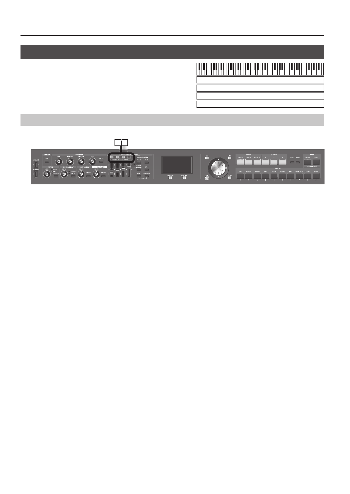
Panel Descriptions
5
Front Panel
2 3
1
10
11
1. [VOLUME] slider
Adjusts the overall volume that is output from the rear panel OUTPUT
jacks, PHONES jack, and BALANCED OUT jacks (p. 18).
2. [V-LINK] Button
Switching this on lets you control external V-LINK compatible video
equipment connected to the RD-700NX (p. 83).
3. EQUALIZER
[LOW] Knob
Adjusts the sound’s low-frequency range (p. 35).
[LOW MID] Knob
Adjusts the sound’s low-midrange frequencies (p. 35).
[HIGH MID] Knob
Adjusts the sound’s high-midrange frequencies (p. 35).
[HIGH] Knob
Adjusts the sound’s high-frequency range (p. 35).
You can adjust the center frequency of each band by holding down
the [EXIT/SHIFT] button and turning the corresponding EQUALIZER
knob ([LOW] knob / [LOW MID] knob / [HIGH MID] knob / [HIGH] knob).
EQUALIZER [ON/OFF] Button
Turns the equalizer on/o (p. 35).
4. REVERB, CHORUS/DELAY, COMPRESSOR, SOUND FOCUS
REVERB [DEPTH] Knob
Adjusts the amount of reverb (p. 33).
[REVERB] Button
Changes the reverb type (p. 33).
CHORUS/DELAY [DEPTH] Knob
Adjusts the amount of chorus (p. 33).
[CHORUS/DELAY] Button
Changes the chorus type (p. 33).
COMPRESSOR [DEPTH] Knob
Adjusts the amount of compression (p. 34).
COMPRESSOR [ON/OFF] Button
Turns the compressor on/o (p. 34).
5
4
SOUND FOCUS [DEPTH] Knob
Allows you to enhance the sound’s de nition (p. 34).
SOUND FOCUS [ON/OFF] Button
Turns Sound Focus on/o (p. 34).
5. LAYER SWITCH/CONTROL
LAYER Switch
Turns each LAYER’s sound on and o (p. 31).
LAYER LEVEL Slider
Adjusts the volume level for each part (p. 31).
If the CONTROL indicator is lit, the sound will change in real time
according to the parameter or function that is assigned (p. 31).
SONG/RHYTHM [SELECT ] Button
Displays a screen where you can select a song or rhythm (p. 37, p. 38).
SONG/RHYTHM [
Start/stops playback of the song or rhythm (p. 37, p. 38)
[CONTROL/LAYER LEVEL] Button
This determines the function of the LAYER LEVEL sliders (p. 73).
[MIDI] Button
Puts the RD-700NX in control of the external MIDI sound generator (p.
86).
[SPLIT] Button
This button selects “Split mode,” whereby the keyboard is divided into
two regions, allowing you to play separate sounds with the right and
left hands (p. 29).
In addition, you can listen to the demo songs by simultaneously
pressing this button and the [TRANSPOSE] button (DEMO PLAY) (p. 25).
[TRANSPOSE] Button
Sets the range of the keyboard to transposed (p. 32).
In addition, you can listen to the demo songs by simultaneously
pressing this button and the [SPLIT] button (DEMO PLAY) (p. 25).
] Button
10
Page 10

6 7 8
9
Panel Descriptions
6. DISPLAY
This shows the Live Set names and the values of various settings, etc.
[LAYER EDIT] Button
This allows you to change the Layer settings (p. 56).
You can also use this to assign functions in some screens.
[TONE EDIT] Button
This allows you to change the tone settings (p. 54).
You can also use this to assign functions in some screens.
[DEC] Button, [INC] Button
These are used to modify values.
If you keep on holding down one button while pressing the other, the
value change accelerates.
VALUE Dial
This is used to modify values.
Cursor [
Press these to switch pages and to move the cursor.
[EXIT/SHIFT] Button
Pressed to return to a previous screen or to cancel a procedure that is
in progress.
Additionally, you can easily call up Edit screens for related parameters
for the following functions by holding down this button while pressing
buttons, turning knobs, or operating other controllers.
[ENTER] Button
This is used to nalize a value or execute an operation.
] [ ] [ ] [ ] Buttons
7. ONE TOUCH
PIANO [CONCERT] Button, [STUDIO] Button, [BRILLIANT] Button
Selects the optimum settings for piano performances (p. 46).
E. PIANO [1] Button, [2] Button, [3] Button
Selects the optimum settings for E. Piano performances (p. 50).
8. FUNCTION
[MENU] Button
Press this button when you wish to adjust various settings (p. 65).
[WRITE] Button
Stores the current settings to “Live Set” (p. 45).
BANK [PRESET] button
Selects a Live Set from the Preset bank.
BANK [USER] button
Selects a Live Set that was saved in the User bank. Live Sets you edit
can be stored in the User bank (p. 45).
9. LIVE SET buttons
These buttons select Live Set categories (p. 27).
When you’re in an edit screen, you can use these buttons to enter
numerical values.
10. [S1] Button, [S2] Button
You can assign various functions to these buttons While performing,
you can press these buttons to use the assigned functions.
11. Pitch Bend/Modulation Lever
This allows you to control pitch bend or apply vibrato (p. 34).
11
Page 11

Panel Descriptions
Rear Panel
12
13
14 15 16 17 18 19 20 21
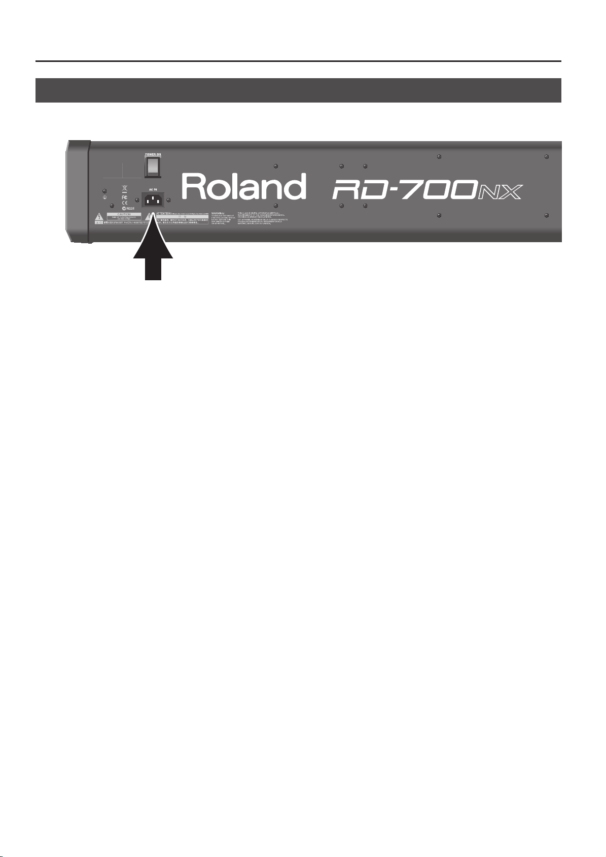
12. [POWER ON] Switch
This switch turns the power on/o (p. 17).
13. AC IN Connector
Connect the included power cord to this connector (p. 14).
14. USB MEMORY Connector
Connect separately sold USB memory or a CD-ROM drive here (p. 18).
Use USB memory or a CD-ROM drive made by Roland.
15. USB MIDI Connector
You can connect this to your computer so that it can exchange
performance data with the RD-700NX (p. 89).
16. [DISPLAY CONTRAST] Knob
Adjusts the display’s contrast (p. 18).
17. PEDAL Jacks (DAMPER, FC1, FC2)
Connecting the pedal switch provided with the RD-700NX to the
DAMPER jack allows you to use the switch as a damper pedal.
With a pedal connected to the FC1 or FC2 jack, you can then assign a
variety of functions to the pedal (p. 72).
18. MIDI Connectors (IN, OUT 1, OUT 2, THRU/OUT 3)
Used for connecting external MIDI devices and for transmission of MIDI
messages (p. 86).
The THRU/OUT 3 connector’s function can be switched to operate
either as MIDI THRU or as MIDI OUT (p. 69).
19. OUTPUT L (MONO)/R Jacks
Provide output of the audio signals. These are connected to an amp or
other device. For monaural output use the L/MONO jack (p. 15).
20. BALANCED OUT L/R Jacks
Connectors for balanced output of the audio signals. Connect to
mixers and other such gear (p. 15).
21. PHONES Jack
A set of headphones can be connected to this jack (p. 15).
Even when headphones are connected, sound will still be output from
the OUTPUT jacks and BALANCED OUT jacks.
12
Page 12
Getting Ready
Align the center
screw on the
bottom of the
RD-700NX with
the center of the
stand.
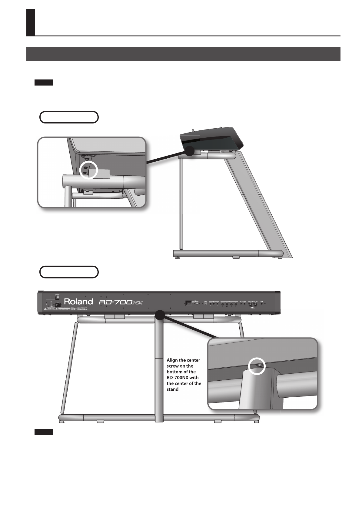
Placing the RD-700NX on a Stand
If you place the RD-700NX on a stand, you must use the KS-G8 (sold separately). When placing the RD-700NX on the KS-G8, place it in the position
shown below.
NOTE
Using the RD-700NX with any other stand may produce an unstable situation, possibly causing the instrument to fall or overturn, and resulting in
injury or damage.
For details on how to assemble the stand, refer to the owner’s manual that accompanied the stand.
Seen from the side
Align the seam in the RD-700NX’s panel (on the
bottom, near the front) with the corners of the
stand’s rubber feet.
Seen from the rear
Align the center
screw on the
bottom of the
RD-700NX with
the center of the
stand.
NOTE
When placing the RD-700NX on the stand, be careful not to pinch your ngers between the instrument and the stand.
13
Page 13
Getting Ready
Connecting the Power Cord
Rear Panel
1. Before you begin making connections, con rm the following.
Is the volume level of the RD-700NX or connected amp turned all the way down?
Is the power to the RD-700NX or connected amp turned o ?
2. Connect supplied power cord to the AC IN connector of the RD-700NX, and plug the other end into an AC outlet.
14
Page 14

Getting Ready
Connecting the External Equipment to RD-700NX
The RD-700NX is not equipped with an ampli er or speakers. In order to produce sound, you need to hook up audio equipment such as a monitor
speaker or a stereo set, or use headphones.
* Audio cables, USB cables, MIDI cables, headphones, expression pedals, and USB memory are not included. Consult your Roland dealer if you need
to purchase accessories such as these.
NOTE
921
To prevent malfunction and/or damage to speakers or other devices, always turn down the volume, and turn o the power on all devices before
making any connections.
Power ampli er
Monitor speakers
(powered)
Computer
Mixer etc.
Stereo
headphones
to Power outlet
Damper pedal
(DP Series)
RD-700NX Rear Panel
Expression pedal (EV-5, EV-7)
or Pedal switch (DP Series)
MIDI IN
MIDI IN
MIDI OUT
Pedal unit
(RPU-3)
MIDI sound module etc.
MIDI sequencer etc.
V-LINK-compatible
video equipment.
15
Page 15
Getting Ready
1. Before you begin making connections, con rm the following.
Is the volume level of the RD-700NX or connected amp turned all the way down?
Is the power to the RD-700NX or connected amp turned o ?
2. Connect supplied power cord to the AC IN connector of the RD-700NX, and plug the other end into an AC outlet.
3. Connect the RD-700NX and the external devices.
Use audio cables to connect audio equipment, such as an amp or speakers.
Use MIDI cables to connect MIDI devices. Use USB cables to connect computer.
If you are using headphones, plug them into the PHONES jack.
Connect pedal switches or expression pedals as necessary.
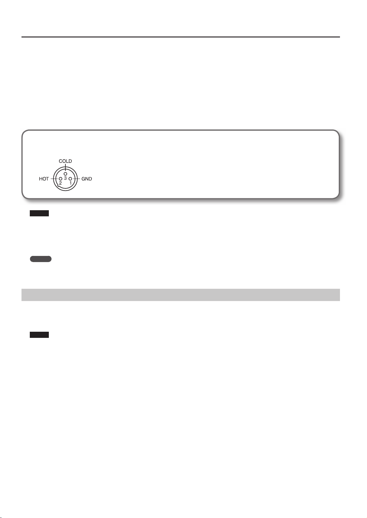
About the Output Jacks
922
RD-700NX is equipped with balanced (XLR) type jacks. Wiring diagrams for these jacks are shown below. Make connections after rst checking
the wiring diagrams of other equipment you intend to connect.
NOTE
• Use Stereo headphones.
Use headphones made by Roland. Using other headphones might not give you enough volume.
925
• Use only the speci ed expression pedal (EV-5, EV-7; sold separately). By connecting any other expression pedals, you risk causing malfunction and/
or damage to the unit.
MEMO
You can connect a commercially available CD drive (sold separately) to the USB MEMORY connector. You can use a CD drive to play back songs from
a CD.
Connecting Pedals
Connect the pedal included with the RD-700NX to one of the PEDAL jacks.
When connected to the DAMPER jack, the pedal can be used as a damper pedal.
Connecting the pedal to the FC1 or FC2 jack allows you to assign a variety of functions to the pedal (p. 57, p. 72).
NOTE
Set the switch on the included pedal to “Continuous” when the pedal is connected.
16
Page 16

Turning the Power On and O
NOTE
941
Once the connections have been completed (p. 15), turn on power to your various devices in the order speci ed. By turning on devices in the wrong
order, you risk causing malfunction and/or damage to speakers and other devices.
Turning On the Power
1. Before you turn on the power, use the [VOLUME] slider to minimize the volume.
Also completely turn down the volume of any connected audio device and other equipment.
Getting Ready
2. Press the upper portion of the [POWER ON] switch on the back of the RD-700NX to turn on the power.
The unit is powered up, and the display’s backlighting comes on.
NOTE
• To prevent incorrect functioning of the Pitch Bend/Modulation Lever (p. 34), refrain from touching the lever while the power to the RD-700NX is
turned on.
942
• This unit is equipped with a protection circuit. A brief interval (a few seconds) after power up is required before the unit will operate normally.
943
• Always make sure to have the volume level turned down before switching on power. Even with the volume all the way down, you may still hear
some sound when the power is switched on, but this is normal, and does not indicate a malfunction.
• In the unlikely event the power is turned o or cut o while Factory Reset (p. 85) is in progress, the data may become corrupted, and it may require
additional time for the unit to start up the next time.
3. Turn on the power to connected external devices.
4. Adjust the volume of the connected external devices.
5. Adjust the RD-700NX’s volume.
Turning O the Power
1. Before you switch on the power, turn the volume down all the way by moving the [VOLUME] slider.
Also completely turn down the volume of any connected audio device and other equipment.
2. Turn o the power to connected external devices.
3. Press the lower portion of the [POWER ON] switch on the back of the RD-700NX.
The power is switched o .
NOTE
945
If you need to turn o the power completely, rst turn o the [POWER ON] switch, then unplug the power cord from the power outlet. Refer to
“Power Supply” (p. 6).
17
Page 17

Getting Ready
Adjusting the Volume
1. Adjust the volume using the [VOLUME] slider.
Move the slider up to increase the volume, or down to lower it.
Also adjust the volume of the connected device to an appropriate level.
Adjusting the Display Contrast
The characters in the display may be di cult to view immediately after turning on the power or after extended use; this may also be because of where
and how the display is situated. In such instances, adjust the display contrast by turning the [DISPLAY CONTRAST] knob on the rear panel.
Rear Panel
Connecting the USB Memory
You can copy Live Set les and song les to separately sold USB memory for safekeeping.
You can also play back SMF music les that’s saved on USB memory, or play audio les from USB memory (p. 38).
1. Connect your USB memory to the USB MEMORY connector located on the RD-700NX’s rear panel.
Rear Panel
NOTE
930
• Never insert or remove a USB memory while this unit’s power is on. Doing so may corrupt the unit’s data or the data on the USB memory.
931
• Carefully insert the USB memory all the way in-until it is rmly in place.
MEMO
If you’re using new USB memory, you must rst initialize (format) it on the RD-700NX. For details, refer to “Formatting Memory (Format)” (p. 81).
18
Page 18

Connecting the CD Drive
If you’re using a stand (KS-G8), you can use the screw holes on the bottom of the RD-700NX to attach a CD drive (sold separately).
MEMO
For information on turning on/o your CD drive and how to insert or remove a CD, refer to the owner’s manual that came with your CD drive.
Getting Ready
1. Connect the USB cable included with the CD drive to the RD-700NX’s USB MEMORY connector.
Rear Panel
NOTE
When connecting the USB cable, make sure that it is oriented correctly, and push it rmly all the way into the connector. Do not use excessive force.
2. Switch on power to the connected CD drive.
3. Switch on the RD-700NX’s power.
NOTE
• Use a CD drive sold by Roland. We cannot guarantee operation if any other CD drive is used.
• CDs that contain both music tracks and data will not play correctly.
• The RD-700NX is capable of playing back only commercial CDs that conform the o cial standards-those that carry the “COMPACT disc DIGITAL
AUDIO” logo.
• The usability and sound quality of audio discs that incorporate copyright protection technology and other nonstandard CDs cannot be guaranteed.
• For details on music discs that incorporate copyright protection technology, please contact the disc manufacturer.
• You cannot save songs to CDs, and you cannot delete songs recorded to CDs. Furthermore, you cannot format CDs.
19
Page 19

Overview of the RD-700NX
Basic Organization of the RD-700NX
The RD-700NX can be divided into two sections: a controller section and a sound generator section.
Controller Section
Sound Generator Section
Play
This section includes the keyboard, the Pitch Bend/Modulation lever,
the panel knobs, the sliders, and any pedal connected to the rear
panel. Actions such as pressing and releasing of keys on the keyboard,
depressing a damper pedal, and so forth, are converted to MIDI
messages and sent to the sound generator section, or to an external
MIDI device.
Sound Generator Section
(controllers such as keyboard, pitch bend lever, etc.)
Controller Section
The sound generator section produces the sound. Here, MIDI
messages received from the controller section or external MIDI device
are converted to musical signals, which are then output as analog
signals from the OUTPUT and PHONES jacks.
About Memory
Memory provides storage locations where Live Sets and other settings are stored. There are three types of memory: “temporary memory,” “rewritable
memory,” and “non-rewritable memory.”
RD-700NX
Non-rewritable memory
Preset memory
Rewritable memory
System memory
User memory
Live Set
300 sets
Temporary memory (Temporary area)
Live Set
Live Set
100 sets
Temporary memory
Temporary area
Data for the patch you select via the front panel buttons is called up to
this area.
When you play the keyboard or play back the SMF, sounds are
produced according to the settings that are in the temporary area.
When you edit a patch, the changes you make do not directly modify
the data in memory; rather, the data is read into the temporary area,
then modi ed.
The settings in the temporary area will be lost when you turn o the
power or call up other settings. If you want to keep the data that’s in
the temporary area, you must store it into rewritable memory.
Rewritable memory
20
Rewritable memory
USB memory
SONG
Live Set
System memory
System memory contains system parameter settings that specify how
the RD-700NX is to operate.
User memory
Live Sets can be stored in user memory.
USB memory (p. 18)
Live Sets and songs can be stored in USB memory in the same way as
in user memory.
Non-rewritable memory
Preset memory
The data in preset memory cannot be rewritten.
If you’ve edited data that was recalled from preset memory, you can
store it in rewritable memory (user memory or USB memory).
Page 20

About Live Sets
The RD-700NX lets you store the sounds that you create.
A sound you create is called a “Live Set”; you can use the buttons to recall a Live Set and then play it.
Live Sets are organized into a “preset bank” and a “user bank.”
Live Set
Controller Section Sound Generator Section
Overview of the RD-700NX
Layer (UPPER 1)
Layer (UPPER 2)
Layer (LOWER 1)
Layer (LOWER 2)
Tone
Tone
Tone
Tone
Rhythm
MFX1 MFX2
MFX1 MFX2
MFX1 MFX2
MFX1 MFX2
Sound
Focus
Reverb
Chorus
Compressor
Equalizer
Rhythm has only
reverb
Layer
The RD-700NX features four parts (UPPER 1, UPPER 2, LOWER 1, and LOWER 2) that you can use for freely controlling the Internal parts with the
RD-700NX’s buttons and keyboard. These four parts that are used for controlling the Internal parts are collectively known as the “Layer.”
Furthermore, you can freely control external MIDI sound generators with the RD-700NX in the same manner as with the Layer. You can likewise control
the external MIDI sound generator with the four parts (UPPER 1, UPPER 2, LOWER 1, and LOWER 2), with this group of four parts being referred to as the
“EXTERNAL Layer.” The external MIDI sound generator is assigned to these four parts for control.
Tone
The individual sounds used when playing the RD-700NX are referred to as “Tones.” Tones are assigned to each layer.
The Tones also include various groups of percussion instrument assembled into “Rhythm Sets.” Each key (note number) of a Rhythm Set will produce a
di erent percussion instrument.
Preset bank
This contains 300 pre-programmed Live Sets.
Although you cannot rewrite the contents of this bank, you are free to create new sounds based on these Live Sets.
User bank
Sounds that you create can be saved in this bank of 100 Live Sets.
For details on how to save a sound, refer to “Storing Settings to Live Sets” (p. 45).
21
Page 21

Overview of the RD-700NX
Basic Operation
Main Screens
985
The explanations in this manual include illustrations that depict what
should typically be shown by the display. Note, however, that your
unit may incorporate a newer, enhanced version of the system (e.g.,
includes newer sounds), so what you actually see in the display may
not always match what appears in the manual.
ONE TOUCH Screen
When the ONE TOUCH PIANO button or ONE TOUCH E. PIANO button
is pressed, setting the RD-700NX to the optimal status for Piano or E.
Piano performances, this screen is displayed (p. 26).
Live Set Screen
The currently selected Live Set is displayed (p. 27).
You can edit this Live Set.
Song/Rhythm Screen
When the SONG/RHYTHM [SELECT] button is pressed, this screen is
displayed.
You can change Rhythm patterns, Songs, and the tempo (p. 37, p. 38).
You can also connect USB memory (sold separately) to the USB
MEMORY connector and play SMF music les or audio les that you’ve
saved in the USB memory.
Tone Wheel Screen
In the Live Set screen, when any ORGAN Tone “Tone Wheel 1–10” is
selected for any of the Layer, this screen is displayed when the Cursor
[ ] button is pressed.
The mode when this screen is displayed is called “Tone Wheel mode,”
and while in this mode you can simulate the creation of sounds using
an organ’s harmonic bars (p. 42).
Pressing the Cursor [EXIT/SHIFT] button when this screen is displayed
returns you to the Live Set screen.
If SMF music le is selected, the measure number is shown in the
upper right of the screen. If an audio le is selected, the playing time is
shown in the upper right of the screen.
Press the [EXIT] button to return to the Live Set screen.
MIDI Screen
When the [MIDI] button is pressed, and the RD-700NX switches to the
mode enabling it to control an external MIDI sound generator.
The status of this button determines whether the RD-700NX’s buttons
are used to control the INTERNAL Layer, or to control the EXTERNAL
Layer.
In addition, you can make detailed settings for the MIDI messages to
be transmitted to the external sound generator (p. 60).
22
Page 22

Overview of the RD-700NX
Special Indications
Indication Explanation
When in the Live Set screen, this symbol will be shown in the
upper-right part of the screen whenever you select a Live
Set that has “TW-Organ 1–10” assigned to any of its layers.
Pressing the Cursor [ ] button while this mark is displayed
brings up the Tone Wheel screen (p. 42).
About the Function Buttons
[MENU] Button
By pressing the [MENU] button to make the indicator light, you can
enter “Edit mode.”
In Edit mode you can make detailed settings for various functions (p. 65).
You can exit Edit mode by pressing the [MENU] button, extinguishing
its indicator.
About the Cursor Buttons
The Cursor buttons are used for switching screens, and for moving to
an item whose setting you want to change (by moving the cursor).
In the LAYER EDIT screen, these buttons are used to select the layer.
Moving Between Display Pages
When arrow symbols (“ ” and “ ”) appear at the upper right of the
display screen, it indicates that there are additional pages in the
directions shown by the arrows.
You can switch screens with the Cursor [
] and [ ] buttons.
[WRITE] Button
Stores the current settings to “Live Set” (p. 45).
Navigating Among Items To Be Set (Cursor)
When more than one parameter is present in a screen, the name and
value of the parameter to be changed is shown with a box around
it. This box is referred to as the “cursor.” The cursor is moved with the
Cursor buttons.
Cursor
Additionally, when multiple parameters are presented horizontally in a
row, as shown in the MIDI screen, you can get the cursor to move more
rapidly by holding down the Cursor button that points in the direction
you want the cursor to move while you also press the Cursor button
that points in the opposite direction.
23
Page 23

Overview of the RD-700NX
Editing a Value
When changing settings values, you can use the [DEC] and [INC] buttons, VALUE dial, or the LIVE SET buttons (numeric keys).
[DEC] Button, [INC] Button
Pressing the [INC] button increases the value, and the [DEC] button
decreases it.
Purpose Panel operation
To continuously
change the value
To rapidly increase
the value
To set the item to
its default value or
turn it o
Hold down the [DEC] button or [INC] button.
While holding down the [INC] button, press the [DEC]
button.
Conversely, you can rapidly decrease the value by
holding down the [DEC] button and pressing the [INC]
button.
Press the [DEC] button and [INC] button simultaneously.
VALUE Dial
Turn the dial clockwise to increase the value, or counterclockwise to
decrease the value.
LIVE SET buttons ( Numeric Keys)
In edit screens, you can use the LIVE SET buttons as [0]–[9] buttons to
directly specify a numerical value.
When you enter the number, the value will blink. This indicates that the
value has not yet been nalized. To nalize the value press the [ENTER]
button.
MEMO
Only numerical values can be entered using the numeric keys.
To switch the positive (+) or negative (-) signs for numerical values
and make continuous changes in the numerical values, press the
[DEC] or [INC] button.
24
Page 24

Listening to the Demo (DEMO PLAY)
Here’s how to listen to these demo songs.
The RD-700NX features the internal demo songs that exhibit the special capabilities of the instrument.
Demo song “Tone Preview” makes e ective use of the internal tones. There are seventeen demo songs, and each of the One Touch buttons and LIVE
SET buttons corresponds to one of the songs.
NOTE
981a
• All rights reserved. Unauthorized use of this material for purposes other than private, personal enjoyment is a violation of applicable laws.
982
• No data for the music that is played will be output from MIDI OUT connectors.
3
2
1
54 2 3
MEMO
When you enter Demo mode, the various settings will be in the same state as they are immediately after the RD-700NX is powered up.
Store any arrangements of settings that you want to keep in Live Set (p. 45).
1. Hold down the [SPLIT] button and press the [TRANSPOSE] button.
The Demo screen appears.
2. Use the Cursor [ ] [ ] buttons, the [DEC] [INC] buttons, or the VALUE dial to select a demo song.
3. Press the [ENTER] button or the [TONE EDIT] (PLAY) button to start playback of the demo song.
When the last song nishes playing, playback will return to the rst song and continue.
4. Press the [EXIT/SHIFT] button or the [LAYER EDIT] (MENU) button to stop a demo song during playback.
MEMO
• If you’ve selected “Tone Preview,” press one of the One Touch buttons or the LIVE SET buttons.
• The demo songs will play consecutively, starting with the song of the button you pressed.
• Pressing a One Touch button or a LIVE SET button during playback stops the song being played, and playback of the newly selected song begins.
5. Press the [EXIT/SHIFT] button or the [LAYER EDIT] (EXIT) button while the song is stopped to nish with the Demo screen.
You will return to the previous screen.
NOTE
The RD-700NX’s keyboard will not produce sound while the demo songs are playing.
25
Page 25
Performance
Piano Performances
Now, try performing with the piano.
The RD-700NX lets you call up the ideal settings for piano performance at any time simply by pressing a button. You can also select your preferred
tones and settings and store them to the RD-700NX’s buttons.
12
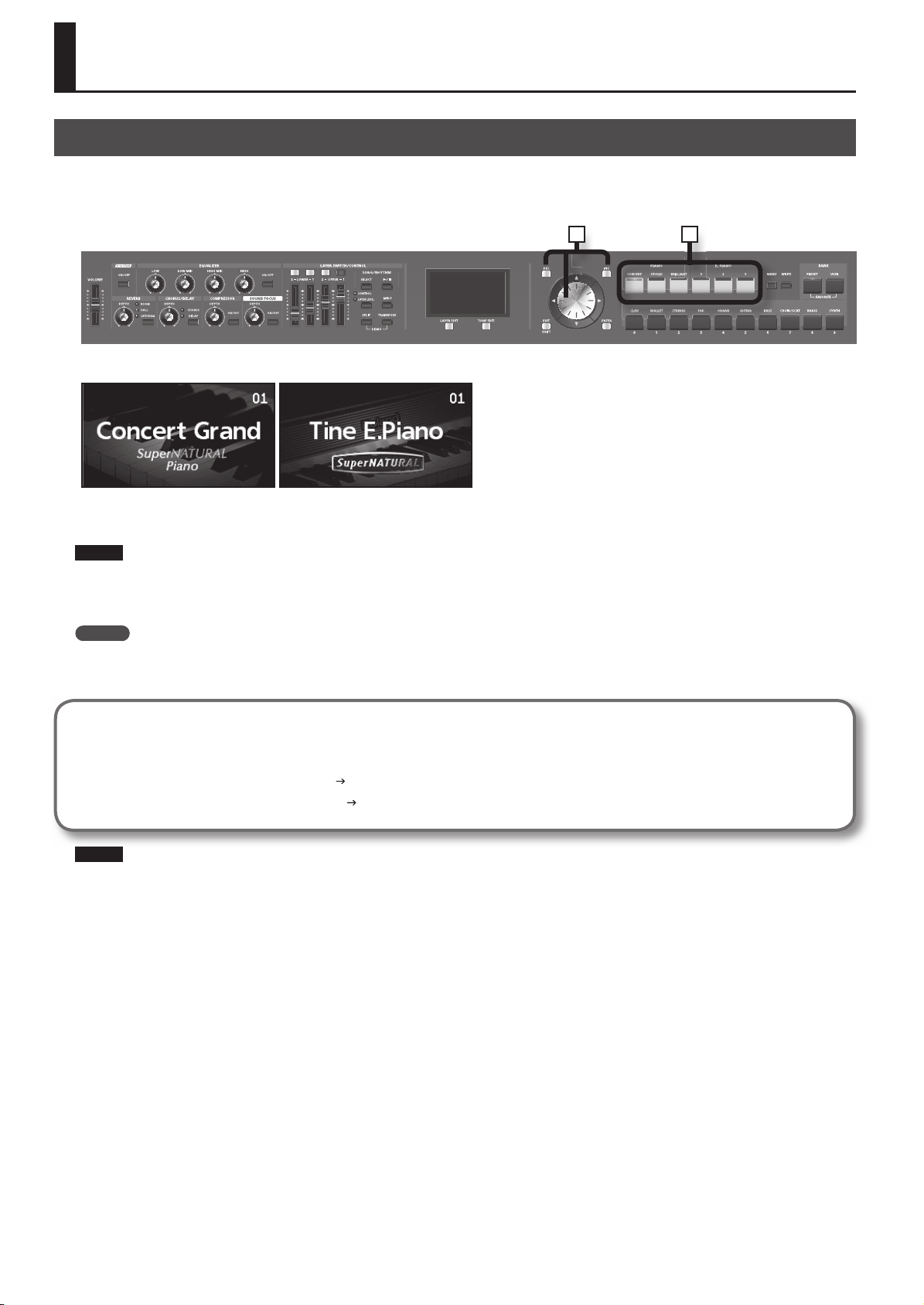
1. Press the ONE TOUCH PIANO button or the ONE TOUCH E. PIANO button.
Pressing the ONE TOUCH PIANO button sets the entire keyboard to play with the piano tone.
Pressing the ONE TOUCH E. PIANO button sets the entire keyboard to play with the electric piano tone.
NOTE
When you press a ONE TOUCH PIANO button or a ONE TOUCH E. PIANO button, all settings other than the tone settings will be set to their power-up
default values. If you want to preserve these settings, store them to a Live Set (p. 45).
2. Use the [DEC] [INC] buttons or turn the VALUE dial to select a variation.
MEMO
By holding down a ONE TOUCH PIANO button or a ONE TOUCH E. PIANO button for several seconds, you can store the variation that’s currently
selected for that button.
The next time you press that button, the stored variation will be selected.
Making Detailed Settings
With the RD-700NX, you can also make more detailed settings to make the sound even better match your favorite piano performances.
Con gurations can be stored for each variation. Please refer to each as needed.
• Making Detailed Settings for the Piano Tones
• Making Detailed Settings for the E. Piano Tones
NOTE
When you edit a setting, an “*” will appear.
If you turn o the power or select a One Touch tone or a Live Set while the “*” is shown, the changes you made will be discarded. If you want to keep
the settings, save the Live Set (p. 45).
p. 46
p. 50
26
Page 26
Performing with a Variety of Live Sets
The RD-700NX comes with a many built-in Sounds.
Each one of these individual sounds is called a “Live Set.”
Live Sets are assigned to the LIVE SET buttons according to the tone category selected.
Each category has several variations.
Try selecting and performing with a number of di erent Live Sets.
2
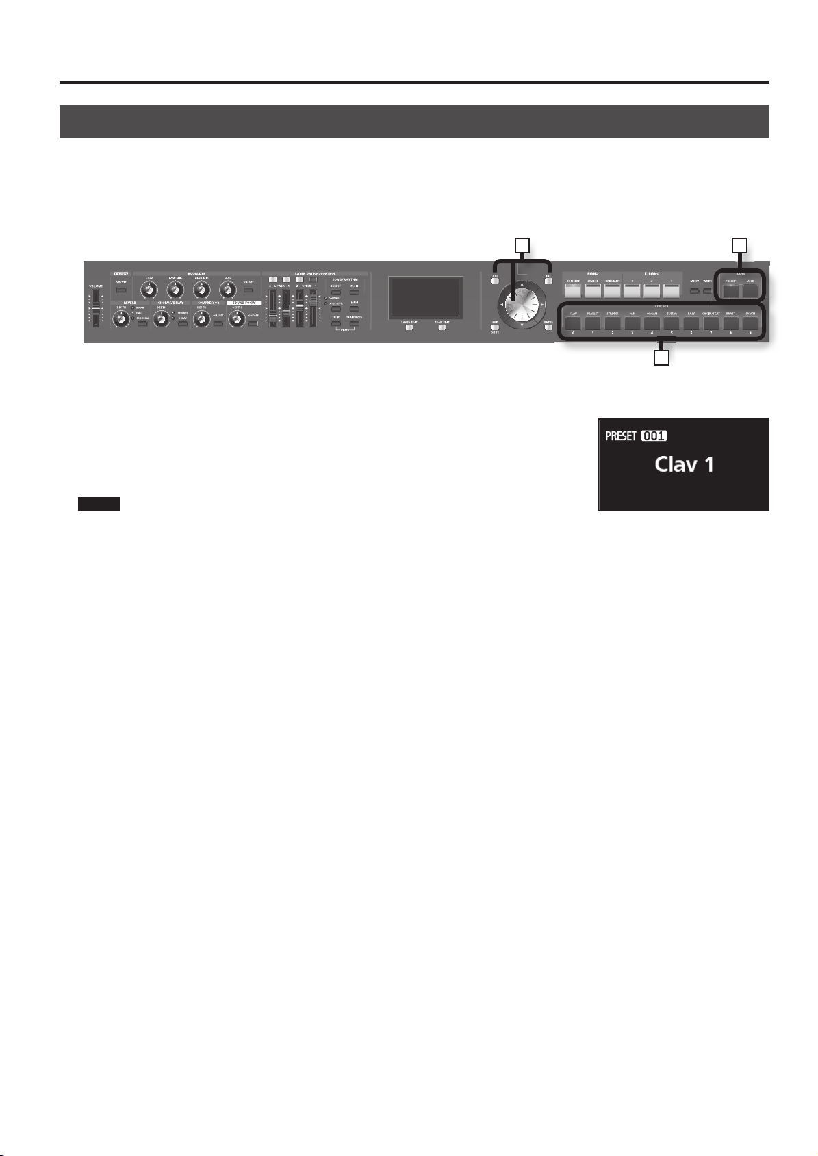
1. Press the BANK [PRESET] button or the BANK [USER] button to select the bank.
The indicator of the selected button will light.
2. Press any of the LIVE SET buttons to select the category.
The indicator of the selected LIVE SET button will light.
3. Use the [DEC] [INC] buttons or VALUE dial to select the tone.
Play the keyboard, and you will hear the selected Live Set.
NOTE
When you edit a setting, an “*” will appear.
If you turn o the power or select a di erent Live Set when an “*” is shown in the display, the setting changes you’ve made will be discarded. If you
want to keep the settings, save the Live Set (p. 45).
Performance
13
27
Page 27
Performance
Playing Multiple Tones with the Keyboard
The RD-700NX features four Internal layers (UPPER 1, UPPER 2, LOWER 1, and
LOWER 2), and one tone can be assigned to each of these layers.
You can perform using combinations of tones by turning each layer on or o .
You can have multiple tones layered together at the same time, and even have
di erent tones played in the left and right parts of the keyboard.
Performing with Layered Tones
You can perform with up to four layered tones applied to the entire keyboard.
1 2
1. Press the [UPPER 1] button and [UPPER 2] button, getting the indicators to light.
Try ngering the keyboard.
The Tones for UPPER 1 and UPPER 2 are layered and played.
UPPER 1
UPPER 2
LOWER 1
LOWER 2
2. Press the [UPPER 2] button once more, and the indicator light goes out.
The Tones for UPPER 1 played.
Likewise, pressing the [LOWER 1] button and [LOWER 2] button lets you then layer four tones.
28
Page 28

Performance
Playing Di erent Tones in Two Di erent Sections of the Keyboard
Such a division of the keyboard into right- and left-hand sections is called a “ Split,” and the key where the division takes place is called the “Split Point.”
While in Split mode, a sound played in the right side is called an “UPPER part,” and the sound played in the left side is called a “LOWER part.” The
split-point key is included in the LOWER section.
The Split Point has been set at the factory to “F#3.”
MEMO
You can change the split point. Please refer to “Changing the Keyboard’s Split Point” (p. 29).
1 2
1. Press the [SPLIT] button, getting the indicator to light.
[LOWER 1] button lights.
Try ngering the keyboard.
The UPPER tone plays in the right-hand section of the keyboard, and the
LOWER tone plays in the left-hand section.
LOWER 1 UPPER 1
2. To exit Split mode, press the [SPLIT] button once more, and the indicator light goes out.
Changing the Keyboard’s Split Point
You can change the point at which the keyboard is divided (the Split Point) in Split mode.
1. Hold down the [SPLIT] button for several seconds.
Current value of the setting is displayed.
2. While holding down the [SPLIT] button, press the key that is to become the new split point.
When you release the [SPLIT] button, the previous display will reappear.
The split-point key is included in the LOWER section.
When you specify the split point, each layer’s key range “LWR (Key Range
Lower)” (p. 56) and “UPR (Key Range Upper)” (p. 56) will be divided to left and right
at the split point, and will be set to the values shown in the table.
MEMO
• When the split point is changed, the Key Range “LWR (Key Range Lower)”
(p. 56), “UPR (Key Range Upper)” (p. 56) value also changes.
• You can change the split point, adjusting it in semitone increments, by
holding down the [SPLIT] button and pressing the [DEC] [INC] buttons. You
can also use the VALUE dial to change the split point.
• You can freely set whatever key ranges you like to each layer. For details,
refer to “LWR (Key Range Lower)” (p. 56), “UPR (Key Range Upper)” (p. 56).
Layer Range
UPPER 1, UPPER 2 Split Point +1–C8
LOWER 1, LOWER 2 A0–Split Point
LOWER 2
Split Point (F#3)
UPPER 1
UPPER 2
LOWER 1
29
Page 29

Performance
Changing the Tone for a Layer
3
1 2
1. Press the [Layer EDIT] button to access the layer edit screen.
2. Use the Cursor [
Layers that have their Layer switch turned o are dimmed in the screen.
3. Use the LIVE SET buttons to select the tone category, and then use the [DEC] [INC] buttons or
the VALUE dial to select a tone.
MEMO
If you use the [ ] [ ] buttons to select a layer whose Layer switch is o (unlit), the Layer switch of the selected layer will blink. If you then press
the blinking button, that layer’s Layer switch will turn on (lit).
] [ ] buttons to select the layer whose tone you want to change.
3
30
Page 30

Performance
Adjusting the Volume Level for Individual Layers
With the RD-700NX, each of the parts that is performed using the internal sound generator is referred to as a Layer.
For each layer (UPPER 1, UPPER 2, LOWER 1, LOWER 2), you can use the Layer switch and Layer LEVEL slider to turn the sound on/o and adjust its
volume.
Layer
Switch
Layer
LEVEL
Sliders
Layer Switch
These buttons turn each layer on/o .
Layers for which the Layer switch indicator is lit (on) will produce sound when you play the keyboard.
Layers for which the Layer switch indicator is unlit (o ) will not produce sound even if you play the keyboard.
Each Layer switch will alternately turn on/o each time it is pressed.
Layer LEVEL Slider
Adjusts the volume of an individual layer.
When a layer’s Layer switch indicator is not lighted, no sound is produced for the layer even when the slider is moved.
MEMO
Use the [VOLUME] slider when adjusting the overall volume level (p. 18).
NOTE
If the CONTROL indicator is lit, you can’t use the Layer LEVEL sliders to adjust the volume (p. 73).
31
Page 31

Performance
Transposing the Key of the Keyboard (TRANSPOSE)
You can transpose performances without changing the keys you are playing, as well as change the pitch by an octave. This feature is called “ Transpose.”
This is a convenient feature to use when you want to match the pitch of the keyboard performance to a vocalist’s pitch, or perform using the printed
music for trumpets or other transposed instruments.
You can adjust the transpose setting in semitone steps over a range of -48–0–+48 relative to C4.
NOTE
Note messages from MIDI IN connector will not be transposed.
1 2 3
1. Hold down the [TRANSPOSE] button for several seconds.
A screen such as the following appears, and the current value of the setting is displayed.
2. Hold down the [TRANSPOSE] button and press a key.
If you press the C4 (middle C) key, the transpose amount will be set to “0.”
For example, to have “E” sound when you play “C” on the keyboard, hold down the [TRANSPOSE] button and press the E4 key. The degree of
transposition then becomes “+4.”
When you release the [TRANSPOSE] button, the previous display will reappear.
When the amount of transposition is set, the Transpose function switches on, and the [TRANSPOSE] button lights up. When the transpose value is set to
“0,” the button’s indicator will remain dark even if you press the [TRANSPOSE] button.
MEMO
You can also transpose by holding down the [TRANSPOSE] button and using the [DEC] [INC] buttons or the VALUE dial.
Even when the Transpose function is turned on, the Split Point remains unchanged (p. 29).
3. To turn o Transpose, press the [TRANSPOSE] button so that its indicator goes o .
The next time [TRANSPOSE] button is pressed, the sound is transposed by an amount corresponding to the value set here.
MEMO
You can set the degree of transposition for each of the Layer individually. For details, refer to “TRA (Transpose)” (p. 56).
NOTE
If the transpose amount is 0, the [TRANSPOSE] button will not turn on even if you press it.
32
Page 32

Adding Reverberation to the Sound (REVERB)
The RD-700NX can apply a reverb e ect to the notes you play on the keyboard.
Applying reverb adds pleasing reverberation to what you play, so it sounds almost as if you were playing in a concert hall.
12
Performance
1. Press the [REVERB] button.
The reverb type switches each time you press the [REVERB] button.
MEMO
Types of reverb other than those listed can be selected in “Reverb Type”
(p. 74) of the “3. E ects” Edit screen. In this case, the [REVERB] button’s
indicator corresponding to the selected type ashes.
TYPE Explanation
OFF (unlit) No reverb is used.
ROOM Simulates the reverberation of a room.
HALL Simulates the reverberation of a large concert hall.
CATHEDRAL Simulates the reverberation of a cathedral.
2. Adjust the REVERB [DEPTH] knob to adjust the amount of reverb e ect to be applied.
Rotating the knob clockwise applies a deeper reverb, and rotating it counterclockwise applies less reverb.
NOTE
When the Layer EDIT’s “Reverb Amount” setting is set to “0,” then no e ect is applied, even when the REVERB [DEPTH] knob is turned (p. 56).
Adding Breadth to the Sound (CHORUS/DELAY)
You can apply a chorus and delay e ect to the notes you play on the keyboard.
By adding the chorus and delay e ect, you can give the sound greater dimension, with more fatness and breadth.
12
1. Press the [CHORUS/DELAY] button.
The chorus type switches each time you press the [CHORUS/DELAY] button.
MEMO
Types of chorus other than those listed can be selected in “Chorus Type”
(p. 75) of the “3. E ects” Edit screen. In this case, the [CHORUS/DELAY]
button’s indicator corresponding to the selected type ashes.
2. Adjust the CHORUS/DELAY [DEPTH] knob to select the amount of chorus e ect to be applied.
Rotating the knob clockwise applies a deeper chorus, and rotating it counterclockwise applies less chorus.
NOTE
When the Layer EDIT’s “Chorus Amount” setting is set to “0,” then no e ect is applied, even when the CHORUS/DELAY [DEPTH] knob is turned (p. 56).
TYPE Explanation
OFF (unlit) Chorus and Delay is not used.
CHORUS
DELAY
You can give the sound greater dimension, with
more fatness and breadth.
This e ect delays the sound to produce an
echo-like e ect.
33
Page 33

Performance
Changing the Sound’s Pitch in Real Time
While playing the keyboard, move the lever to the left to lower the pitch, or to the right to raise the pitch. This is known as Pitch Bend.
You can also apply vibrato by manipulating the lever away from you. This is known as Modulation.
If you move the lever away from you and at the same time move it to the right or left, you can apply both e ects simultaneously.
NOTE
The e ect obtained when you move the lever may di er according to the
tone being used. Additionally, the e ect applied by moving the lever is
predetermined for each tone, and cannot be changed.
MEMO
When the Tone Wheel screen is shown, moving the pitch bend lever to left or
right will switch the Rotary e ect between fast and slow. For details, refer to
“Simulating the Creation of Organ Tones” (p. 42).
Pitch Bend
Adding Liveliness to the Sound (COMPRESSOR)
Switching on the Compressor suppresses di erences in volume for a more consistent sound.
This is set to OFF when the power is turned on.
Modulation
1 32
1. Press the COMPRESSOR [ON/OFF] button, getting its indicator to light.
2. Use the COMPRESSOR [DEPTH] Knob to adjust the depth of the e ect.
Turning the knob toward the right will deepen the e ect, and turning it toward the left will lessen the e ect.
3. To cancel this function, press the COMPRESSOR [ON/OFF] button once more, extinguishing the indicator.
NOTE
Sounds may become distorted with certain tones.
MEMO
You are free to edit the compressor settings. Refer to “Making the Compressor Settings” (p. 76).
Enhancing the sound’s defi nition (SOUND FOCUS)
The sound can be made more prominent by turning on Sound Focus.
1 32
1. Press the SOUND FOCUS [ON/OFF] button, getting its indicator to light.
2. Use the SOUND FOCUS [DEPTH] Knob to adjust the depth of the e ect.
Turning the knob toward the right will deepen the e ect, and turning it toward the left will lessen the e ect.
3. To cancel this function, press the SOUND FOCUS [ON/OFF] button once more, extinguishing the indicator.
NOTE
Sounds may become distorted with certain tones.
MEMO
The Sound Focus Type setting lets you specify the Sound Focus e ect. For details, refer to “Making Tone Settings” (p. 54).
34
Page 34

Performance
Adjusting the Levels of Each Frequency Range (EQUALIZER)
The RD-700NX is equipped with a four-band equalizer.
You can use the EQUALIZER [LOW] knob, [LOW MID] knob, [HIGH MID] knob, and [HIGH] knob to adjust the level of each frequency range.
By holding down the [EXIT/SHIFT] button and turning the corresponding knob, you can adjust the center frequency of each frequency range.
NOTE
Equalization is applied to the overall sound output from the OUTPUT jacks.
1 32
1. Press the EQUALIZER [ON/OFF] button to make its indicator light.
A screen like the one shown below appears, and the equalizer is turned on.
2. Turn the knobs to adjust the levels and the frequency in each range.
Rotating a EQUALIZER knob ([LOW] knob, [LOW MID]
knob, [HIGH MID] knob, [HIGH] knob) in the negative
direction cuts the level of that frequency range;
rotate it in the positive direction boost the level of
that range.
In addition, holding down the [EXIT/SHIFT] button
and turning a knob toward the negative direction
will lower the frequency, and turning it toward the
positive direction will raise the frequency.
You can press the [TONE EDIT] (NUMERIC)button to get a numerical reading for the value of the setting. Pressing the [TONE EDIT] (NUMERIC) button
toggles you between “NUMERIC” and “GRAPHIC” as the format for what you see indicated in the screen.
The way settings are made di ers depending on the format used, as follows:
GRAPHIC NUMERIC
When the Graphic format is used
• Slightly adjust the knob for the range in which you want to change the value to move the cursor.
• Press the Cursor [
• Press the Cursor [
] [ ] buttons to adjust the frequency.
] [ ] buttons to adjust the Q.
When the Numeric format is used
• Press the Cursor [ ] [ ] [ ] [ ] buttons to move the cursor.
• Press the [DEC] [INC] buttons to change the value.
• Repeatedly press the [Layer EDIT] (BAND) button to step through the frequency ranges for editing.
• In the low range (LOW) and high range (HIGH) screens, you can switch the equalizer type.
Parameter Value
Type Shelving, Peaking
3. To turn the equalizer o , press the EQUALIZER [ON/OFF] button, extinguishing its indicator.
MEMO
You can set the RD-700NX so that the equalizer settings are not changed when you change Live Sets (p.
44). Refer to“Preventing Equalizer Settings from Being Switched (EQ Mode)” ( p. 67).
NOTE
Sounds may be distorted with certain knob settings. If this occurs, adjust the Input Gain on the upper of the “NUMERIC” screen.
35
Page 35

Performance
Disabling the Button
By engaging the Panel Lock function, you can disable panel functions. This prevents settings from being changed inadvertently on stage or in other
such situations.
However, you’ll still be able to operate the following buttons and knobs even while Panel Lock is in force.
• [VOLUME] slider
• [DISPLAY CONTRAST] knob
• Pitch Bend/Modulation lever
• Pedals
• ONE TOUCH PIANO buttons
• ONE TOUCH E. PIANO buttons
• [EXIT/SHIFT] button
1. While holding down the [MENU] button, and press the [ENTER] button.
A screen like the one shown at right will appear.
2. Press the ONE TOUCH PIANO buttons, the ONE TOUCH E. PIANO buttons, or the [EXIT/SHIFT]
button to cancel Panel Lock.
MEMO
You can assign the Panel Lock function to the [S1] button or [S2] button. Refer to “Assigning the [S1] [S2]
buttons When S1/S2 Mode is Set to “SYSTEM”” (p. 68).
36
Page 36

Using the Convenient Functions in Performances
Playing Rhythm
The RD-700NX features internal drum patterns complementing Jazz, Rock, and other various musical genres. These drum patterns are referred to as
“ Rhythms.”
1 3
2
1. Press the [SELECT] button to make the button indicator light.
The SONG/RHYTHM screen will appear.
2. Press the [Layer EDIT] (SONG/RHYTHM) button to access the RHYTHM screen.
Each time you press the [Layer EDIT] (SONG/RHYTHM) button, you’ll alternate between the SONG screen and the RHYTHM screen.
3. Press the [ ] button so it’s lit; the rhythm will begin sounding.
When you press the [ ] button once again to turn o its light, the rhythm will stop.
MEMO
If you press the [Layer EDIT] (SONG/RHYTHM) button to switch to the SONG screen while a rhythm is playing, the rhythm will stop.
Changing Rhythm Tempos
1. In the Rhythm screen, press the Cursor [ ] button to move the cursor to the tempo
indication in the top line of the screen.
2. Use the [DEC] [INC] buttons or VALUE dial to change the tempo.
The Rhythm are played at the selected tempo.
MEMO
The way Rhythm is played and the tempo display may di er with some Rhythm Patterns.
If you press the [MENU] button and then choose “6. Rhythm,” you’ll be able to edit a variety of other settings in addition to the rhythm’s tempo and
pattern. For details, refer to “Making the Rhythm Settings” (p. 82).
Changing the Rhythm Pattern
You can select the way a Rhythm is played (the pattern) to match a variety of di erent musical genres.
1. In the RHYTHM screen, use the cursor [ ] [ ] buttons to move the cursor to the rhythm
number shown in the screen.
2. Use the [DEC] [INC] buttons or VALUE dial to change the patterns.
The rhythm’s pattern will change.
3. To stop the rhythm, press the [ ] button so its indicator is o .
37
Page 37

Using the Convenient Functions in Performances
Playing the Songs
Here’s how to play back SMF music les, audio data, or songs from a CD.
MEMO
You can play songs that are saved on USB memory (sold separately). For details, refer to “Connecting the USB Memory” (p. 18).
If you want to connect a separately sold CD drive and play back songs from a CD, refer to the owner’s manual of your CD drive.
1 3
2
1. Press the [SELECT] button to make the button indicator light.
The SONG/RHYTHM screen will appear.
2. Press the [Layer EDIT] (SONG/RHYTHM) button to access the SONG screen.
Each time you press the [Layer EDIT] (SONG/RHYTHM) button, you’ll alternate between the SONG screen and the RHYTHM screen.
3. Press the [ ] button so it’s lit; the song will begin playing.
When you press the [ ] button to turn o its light, the song will stop playing.
NOTE
Even if you change the Live Set while a song is playing, the tempo won’t change.
If you change the Live Set while song playback is stopped, the tempo will be changed to the tempo that is stored in the Live Set.
Selecting the Song
1. In the SONG screen, use the [ ] [ ] buttons to move the cursor to the media indication in
the screen.
2. Use the [DEC] [INC] buttons or the VALUE dial to select the desired media.
Type Explanation
INT Songs in the RD-700NX’s internal memory
USB
3. Press the Cursor [ ] button to move the cursor to Song number.
4. Use the [DEC] [INC] buttons or the VALUE dial to select a song.
5. Press the [
When Selecting Songs in Folders
1. Use the [DEC] [INC] buttons or the VALUE dial to select the folder containing the song you want to play back.
(folder) icon is shown.
2. Press the [ENTER] button.
The songs in the folder will be displayed.
3. Use the [DEC] [INC] buttons or the VALUE dial to select a song.
To exit the folder, use the [DEC] [INC] buttons or VALUE dial to select “up,” then press the [ENTER] button.
Songs in USB memory connected to the USB MEMORY connector
Songs on a CD in a CD drive connected to the USB MEMORY connector
] button so it’s lit; the song will begin playing.
NOTE
If a single folder contains 500 or more les and folders, some les or folders may not be displayed.
MEMO
Song number “000” is programmed with a Preset song.
Enjoy performing on the keyboard along with this song as it is played back.
38
Page 38

Using the Convenient Functions in Performances
Changing Song Tempos
1. In the SONG screen, press the Cursor [ ] button or [ ] button to move the cursor to the
tempo indication in the top line of the screen.
If an audio le is selected, the value will be indicated as a percentage.
2. Use the [DEC] [INC] buttons or the VALUE dial to change the tempo.
The song are played at the selected tempo.
Fast-forwarding or Rewinding a Song
1. In the SONG screen, press the Cursor [ ] button or [ ] button to move the cursor to the
measure indication in the upper right of the screen.
If an audio le is selected, the indication will be the playback time.
2. Use the [DEC] [INC] buttons or the VALUE dial to change the value.
The playback position will change as shown by the indication.
Return to the Beginning of the Song
1. In the SONG screen, hold down the [EXIT/SHIFT] button and press the [DEC] button.
Caution when Playing Back Audio Files
Playing back an MP3 le or changing the playback tempo of an audio le places a signi cant processing burden on the RD-700NX, and in some cases
may cause it to be unable to completely process all of the performance data from the keyboard.
If this occurs, you may be able to solve the problem by taking the following actions.
• Use WAV format data rather than MP3 format data
• Return the song tempo to its original setting (to 0%)
39
Page 39

Using the Convenient Functions in Performances
Recording Audio
The RD-700NX lets you easily record your performance as an audio le.
You can then play back the recording to evaluate your performance.
3 7 8
64 5 9 10
Getting ready to record
NOTE
You must not disconnect the USB memory.
1. Connect your USB memory to the external memory connector (p. 18).
2. Select the tone that you want to play (p. 27).
3. Press the [SELECT] button.
4. Press the [Layer EDIT] (SONG/RHYTHM) button to access the SONG screen.
5. Press the [TONE EDIT] (REC) button.
The display will indicate “New Song.”
The [TONE EDIT] (REC) button will light, the [
If you decide to cancel recording, press the [TONE EDIT] (STOP) button.
] button will blink, and the RD-700NX will enter recording-standby mode.
Starting/stopping recording
6. Press the [ ] button.
The [ ] button will light, and recording will begin.
7. Press the [ ] button.
Recording will stop, and a screen will appear, allowing you to rename the song.
You can also stop recording by pressing the [TONE EDIT] (REC) button.
8. Use the cursor [ ][ ] buttons to move the cursor to the position where you want to enter a character.
9. Use the [DEC] [INC] buttons or the VALUE dial to enter the desired name.
Pressing the [Layer EDIT] (DELETE) button will delete one character, and pressing the [TONE EDIT] (INSERT) button will insert one character of blank
space.
MEMO
You can also use the LIVE SET buttons to specify and enter characters directly.
10. Repeat steps 3–4 to enter the desired name.
By pressing the [EXIT/SHIFT] button, you can save the song to USB memory without changing its name.
11. Press the [ENTER] button to con rm the name.
The song will be saved.
NOTE
Never disconnect the USB memory while the screen indicates “Executing...”
40
Page 40

Using the Convenient Functions in Performances
Applying E ects to the Sound (MFX)
In addition to chorus (p. 33) and reverb (p. 33), the RD-700NX also allows you to apply “multi-e ects” to sounds. Multi-e ects provides a collection of 84
di erent e ects, such as distortion and rotary, from which you can choose.
You can simultaneously use two multi-e ects for each layer; they are referred to as MFX 1 and MFX 2.
The factory settings have a suitable e ect assigned to each of the tones.
1. Access the Live Set screen (p. 27).
2. Press the [TONE EDIT] button.
The [TONE EDIT] button will light, and the TONE EDIT screen will appear.
3. Use the cursor [ ] [ ] buttons to choose MFX 1 or MFX 2.
4. Use the cursor [
5. Use the [DEC] [INC] buttons or the VALUE dial to set the desired value.
6. When you’ve nished editing, press the [TONE EDIT] button so its indicator goes out.
You will return to the Live Set screen.
NOTE
E ects are not applied to Tones for which the TONE EDIT MFX 1/MFX 2 settings are set to “0 THRU” (p. 54).
MEMO
You can switch the multi-e ect on/o and adjust its depth for the tone of the currently selected layer. By switching layers, you can adjust the tone
settings for each layer (p. 30).
] [ ] buttons to move the cursor to the parameter that you want to edit.
41
Page 41

Using the Convenient Functions in Performances
Simulating the Creation of Organ Tones
When any of the “TW-Organ 1–10” Tones is selected for any of the layer, you can perform in “ Tone Wheel mode,” in which the creation of organ sounds is
simulated.
An organ features nine “harmonic bars” that can be drawn in and out, and by using the bars in di erent combinations of positions, a variety of di erent
tones can be created. Di erent “Feet” are assigned to each bar, with the pitches of the sounds being determined by these “Feet.” You can simulate the
creation of tones using the harmonic bars by assigning Feet to the Layer LEVEL sliders.
While there are only four Layer LEVEL sliders, you can switch the Feet setting by turning the Layer switch buttons on and o , thus allowing you to
assign eight Feet settings to the sliders.
What Are “ Feet?”
Feet basically refers to the lengths of pipe used in pipe organs. The length of pipe used to produce the reference pitch (the fundamental) for the
keyboard is eight feet. Reducing the pipe to half its length produces a pitch one octave higher; conversely, doubling the pipe length creates a
pitch one octave lower. Therefore, a pipe producing a pitch one octave below that of the reference of 8’ (eight feet) would be 16’; for one octave
above the reference, the pipe would be 4’, and to take the pitch up yet another octave it would be shortened to 2’.
1. Access the Live Set screen (p. 27).
2. Select a Live Set to which one of the “TW-Organ 1–10” tones is assigned.
3. Press the Cursor [
The Tone Wheel screen will appear.
This Tone Wheel screen appears only when a Tone Wheel Tone is selected for one of the Layer.
] button.
4. When the Layer LEVEL sliders are moved, the harmonic bars move in the display, and the
tone changes.
By pressing the Layer switch buttons on and o , you can adjust the sounds for other Feet.
If the cursor is moved to the value at the bottom of the screen, you can adjust the sounds for Feet with the [DEC] [INC] buttons.
5. Press the Cursor [ ] [ ] buttons to move the cursor to “Perc” and press the [DEC] [INC] buttons to change the value.
Perc (Percussion) adds an attack-type sound to the beginning of the note to give the sound more crispness. The attack sound changes according to the
value.
Setting Description
OFF No percussion is added.
2nd Percussion sounds at a pitch one octave above that of the key pressed.
3rd Percussion sounds at a pitch an octave and a fth above that of the key pressed.
Slow The percussion’s attenuation time is lengthened. This softens the sense of attack.
Fast
The percussive sound will decay more quickly. This gives more of a sense of attack for a sharp
sound.
NOTE
When percussion is on, the 1’ pitch will not be produced.
Even if you’ve edited the tone wheel settings, they will return to their previous state if you select ONE TOUCH PIANO, ONE TOUCH E. PIANO, or a Live
Set. If you want to keep the changes you made, save the Live Set (p. 45).
42
Page 42

Using the Convenient Functions in Performances
Changing the Undulation of the Organ Tone (Rotary Eect)
While the Tone Wheel screen is displayed, you can change the undulation rate of the Rotary eect with the Pitch Bend lever.
The Rotary eect is an eect that recreates the sound of the rotating speakers used to augment the sound of an organ.
Moving the pitch bend lever to left or right will toggle the Rotary eect between fast and slow regardless of the direction in which you move the lever.
MEMO
This Pitch Bend Lever setting is eective only in the Tone Wheel screen.
Changing the Layer LEVEL Slider Feet Assignments
You can change the Feet assigned to each of the Layer LEVEL sliders used in Tone Wheel mode.
1. Press the [MENU] button, getting the indicator to light.
The Edit Menu screen appears.
2. Press the Cursor [ ] [ ] buttons to select “2.Control.”
3. Press the [ENTER] button to display the Edit screen.
4. Press the Cursor [
] [ ] buttons to select “Harmonic Bar.”
Footage assignments in the Tone Wheel screen (from the left of the screen)
’
5-1/3’ 8’ 4’ 2-2/3’ 2’ 1-3/5’ 1-1/3’ 1’
16
5. Press the Cursor [ ] [ ] buttons to move the cursor to the parameter for changing the Feet.
“LED ON” and “LED OFF” in the screen indicate whether Layer switch is switched on or o.
Parameter Value
UP 1 (UPPER 1)
UP 2 (UPPER 2)
LW 1 (LOWER 1)
LW 2 (LOWER 2)
16’, 5-1/3’, 8’, 4’, 2-2/3’, 2’, 1-3/5’, 1-1/3’, 1’
6. Use the [DEC] [INC] buttons or the VALUE dial to select the Feet.
7. When you have nished making the settings, press the [MENU] button, extinguishing its indicator.
You are returned to the Live Set screen.
43
Page 43

Using the Convenient Functions in Performances
Selecting Stored Settings (Live Set )
The RD-700NX’s Layer (p. 56) and EXTERNAL Layer (p. 59) tone settings, e ect settings, and other such settings are collectively referred to as a “ Live Set.”
Once you’ve stored your preferred settings, and settings for the songs to be performed as a Live Set, you can then switch whole groups of settings
during a performance just by switching Live Sets.
You can store up to 100 Live Sets. The Preset bank contains recommended Live Sets.
Now try actually calling up a Live Set.
NOTE
The current settings are erased when a Live Set is called up.
When you’ve created settings that you like, you should store them in the User bank. For details on how to store your settings in the User bank, refer
to “Storing Settings to Live Sets” (p. 45).
1. Press the LIVE SET button, getting the indicator to light.
The Live Set screen will appear.
2. Use the [DEC] [INC] buttons, VALUE dial, or LIVE SET buttons to select the Live Set to be called up.
Registering the Live Sets You Like
You can also register the Live Sets you like and use frequently to the LIVE SET buttons.
These Live Sets are called “Favorite Live Sets.”
This function allows you to select Live Sets more quickly.
You can register a total of 40 Live Sets, ten Live Sets in each of the four banks, to the Favorite Live Sets.
1. In the Live Set screen, recall the Live Set that you want to register.
2. Hold down the BANK [PRESET] button and press the BANK [USER] button.
The Favorite Live Set screen will appear.
3. Use the [TONE EDIT] (BANK CHANGE) button to select the bank in which you want to register the Live Set.
4. Hold down the [Layer EDIT] (ASSIGN) button and press the LIVE SET button at which you want to register the Live Set.
The Live Set will be registered to the button you pressed.
5. To return to the Live Set screen, press the [EXIT/SHIFT] button.
MEMO
Settings registered in the RD-700NX are not deleted even when the power is turned o .
Selecting a Live Set You’ve Registered
1. Hold down the BANK [PRESET] button and press the BANK [USER] button.
The Favorite Live Set screen will appear.
2. Press the [TONE EDIT] (BANK CHANGE) button to select the desired bank.
When you press the [Layer EDIT] (ASSIGN) button, the screen will show a list of the Live Sets registered to the buttons of the selected bank.
MEMO
There are four banks (A–D). Repeatedly pressing the [TONE EDIT] (BANK CHANGE) button cycles you through the banks in this order: A B C D
A ...
You can switch screens by holding down the [Layer EDIT] (ASSIGN) button and using the cursor [
3. Press one of the LIVE SET buttons to select the desired Live Set.
4. Play the keyboard.
The settings of the Live Set you recalled will be placed in e ect.
5. To return to the Live Set screen, press the [EXIT/SHIFT] button.
44
] [ ] buttons.
Page 44

Using the Convenient Functions in Performances
Storing Settings to Live Sets
If you want to use the changed content as a new Live Set, use the following procedure to save the settings to user bank.
You can store 100 Live Sets on the RD-700NX.
You can also change the name of a Live Set.
1. Press the [ WRITE] button, getting the indicator to light.
As shown on the right screen appears.
2. Press the Cursor [ ] [ ] buttons to move the cursor to the
positions where the characters are to be input.
3. Use the [DEC] [INC] buttons or the VALUE dial to enter the
characters.
The following characters are available.
space, ! “ # $ % & ‘ ( ) * + , - . / 0–9 : ; < = > ? @ A–Z [ \ ] ^ _ ` a–z { | } ~
When the [TONE EDIT] (INSERT) button is pressed, a single-character blank space is inserted; pressing the [Layer EDIT] (DELETE) button deletes one
character.
MEMO
You can use the LIVE SET buttons to directly specify and enter characters.
4. Repeat steps 2–3 to input the name.
5. Press the Cursor [
] button to move the cursor to the destination Live Set number.
MEMO
Pressing the Cursor [ ] button, even while inputting the name, moves the cursor to the save-destination Live Set number.
6. Select the save-destination Live Set number, either by using the [DEC] [INC] buttons or the
VALUE dial.
When using the LIVE SET buttons to input Live Set numbers, press the [ENTER] button afterwards to set the
number.
New Live Set Name
Destination
7. When you have nished determining the save destination and the name for the new Live Set,
press the [ENTER] button or the [Layer EDIT] (WRITE) button.
The [ENTER] button’s indicator is ashing, and the con rmation message appears.
If you do not want to save the Live Set, press the [EXIT/SHIFT] button or [WRITE] button.
8. When the [ENTER] button is pressed, saving of the Live Set begins.
When you have nished saving the Live Set, the [WRITE] button’s indicator goes out and you are returned to
the Live Set screen.
NOTE
Never switch o the power while “Executing...” appears in the display.
Settings Not Saved in a Live Set
The following settings cannot be saved to a Live Set.
• System Settings (p. 66)
• Compressor Settings (p. 76)
• V-LINK Settings (p. 83)
• Settings for Play Mode, Transpose, Center Cancel, and Part Switch under Song Function. (p. 84)
• Rec Setting (p. 86)
Pressing the [Layer EDIT] (WRITE) button in the Edit screen saves the System, and V-LINK settings.
45
Page 45

Making Detailed Settings for the ONE TOUCH Tones
Making Detailed Settings for the Piano Tones
You can make detailed settings to adjust the piano sound that’s used when you press the ONE TOUCH PIANO button (p. 26).
These detailed settings can be saved for each variation.
NOTE
When you press one of the ONE TOUCH PIANO buttons, all settings other than the tone settings will be set to their power-up default values.
Store any arrangements of settings that you want to keep in Live Set (p. 45).
1. In the ONE TOUCH PIANO screen, use [DEC] [INC] or the VALUE dial to select the variation that you want to edit.
2. Press the [TONE EDIT] button.
The tone edit screen will appear.
3. Press the Cursor [ ] [ ] buttons to switch screens, and press the Cursor [ ] [ ] buttons to move the cursor to the parameter
to be set.
Move the cursor to one of the following menus and press the [ENTER] button, then select the parameter you want to set in the screen that follows.
1. Key Touch Edit
2. Micro Tune Edit
3. Sym. Resonance
4. Equalizer
5. Initialize
4. Use the [DEC] [INC] buttons or the VALUE dial to edit the value.
For details on the parameters, refer to the Piano Parameters table.
5. If you want to save the setting, press the [LAYER EDIT] (WRITE) button.
The conrmation message appears.
Press the [ENTER] button to save the settings. If you want to cancel, press the [EXIT/SHIFT] button, you are returned to the MENU screen.
6. When you nish making settings, press the [EXIT/SHIFT] button.
You are returned to the ONE TOUCH PIANO screen.
NOTE
Depending on the piano tone selected, this setting may not be available.
46
Page 46

Making Detailed Settings for the ONE TOUCH Tones
Piano Parameters
Parameter Value Description
(Tone Name) – Selects the tone.
Stereo Width CENTER, L01-01R–L63-63R The higher the value set, the wider the sound is spread out.
Nuance TYPE1, 2, 3
Lid 1–7
Damper Noise 0–127
Duplex Scale 0–127
This changes the Tone’s subtle nuances by altering the phase of the left and right sounds.
* This e ect is di cult to hear when headphones are used.
Reproduces the way the brightness of a grand piano’s sound is a ected by how much the piano’s lid is
opened.
The lid is opened more as the value is increased, creating a brighter sound.
This adjusts the damper noise (the sound that occurs when the strings of an acoustic piano are released
by pressing the damper pedal).
Increasing this value will increase the sound that is heard when the strings are released.
This adjusts the sound of the sympathetically vibrating aliquot strings on an acoustic piano.
Higher values will increase the volume of the sympathetic vibration.
What are Duplex Scale?
“Duplex Scale” refers to a system that causes sympathetic vibrations in the sections of the
string toward the front and toward the back.
It can produce sound that is richer and brighter by adding the string’s higher harmonics.
Because no damper (sound-stopping mechanism) is applied to the front or back sections of
the string, the resonating sounds linger even after the sound of the string stops when you
release the played key.
String Resonance OFF, 1–127
Key O Resonance OFF, 1–127
Hammer Noise -2–0–+2
Tone Character -5–0–+5 Higher values produce a harder sound; lower values produce a more mellow sound.
Sound Lift 0–127
When the keys are pressed on an acoustic piano, the strings for keys that are already pressed also vibrate
sympathetically. The function used to reproduce is called “String Resonance.”
Increasing the value will increase the amount of e ect.
This adjusts resonances such as the key-o sound of an acoustic piano (subtle sounds that are heard
when you release a key).
Higher values will increase the volume of the resonances.
This adjusts the sound of the hammer striking the string of an acoustic piano.
Higher values will increase the sound of the hammer striking the string.
This lets you change the way that the sound will respond when you play the keyboard softly. For
example, this can be adjusted suitably for solo performance, or to prevent your sound from being buried
in the rest of the band.
Increasing this value will allow fairly loud sounds to be produced even when you play with a light touch,
so that your performance will not be obscured by the playing of your band.
* The tonal change will still be great even if you change this value.
47
Page 47

Making Detailed Settings for the ONE TOUCH Tones
Changing the Key Touch
You can make advanced settings for the touch used for the keys.
Changing this setting also changes the Key Touch setting in Edit Mode
(p. 71).
Parameter Value Description
SPR LIGHT An even lighter setting than LIGHT.
This sets the keyboard to a light
touch. You can achieve fortissimo ()
play with a less forceful touch than
usual, so the keyboard feels lighter.
This setting makes it easy to play,
even for children.
This sets the keyboard to the
standard touch. You can play with
the most natural touch. This is the
closest to the touch of an acoustic
piano.
This sets the keyboard to a heavy
touch. You have to nger the
keyboard more forcefully than usual
in order to play fortissimo (), so
the keyboard touch feels heavier.
Dynamic ngering adds even more
feeling to what you play.
This setting provides even more
precise adjustment of the key touch
than available with the Key Touch
setting alone.
This allows you to achieve a more
precise setting for the Key Touch by
specifying an intermediate value
between Key Touch settings. The
touch sensitivity becomes heavier as
the value increases.
When this parameter is set to a value
that exceeds the upper or lower
limit, the setting for Key Touch (one
of ve possible values) is automatically changed to accommodate the
value you’ve specied.
Key Touch
Key Touch
Oset
LIGHT
MEDIUM
HEAVY
SPR HEAVY An even heavier setting than HEAVY.
-10–+9
Finely Adjusting the Tuning
This procedure allows micro-tuning of each individual key.
You can adjust this in a range of -50.0 to +50.0 cents in 0.1 cent steps.
(One semitone is 100 cents.)
Parameter Value
Type OFF, PRST (PRESET), USER
1. In step 3 of “Making Detailed Settings for the Piano Tones”
(p. 46), choose “2. Micro Tune Edit” and press the [ENTER]
button.
The Micro Tune Edit screen appears.
Pressing the [EXIT/SHIFT] button returns you to the previous screen.
2. Press the Cursor [ ] button to move the cursor to the value
for “TYPE.”
3. Use the [DEC] [INC] buttons or the VALUE dial to select the
type.
4. Press the Cursor [
numerical value.
5. Press the key to specify it as the one you want to tune.
6. Use the [DEC] [INC] buttons or the VALUE dial to adjust the
value.
7. If you want to save the setting, press the [LAYER EDIT]
(WRITE) button.
The setting is saved to “USER.”
] button to move the cursor to the
Parameter Value Description
Volume levels and the way sounds
are played change in response to
the velocity.
The xed velocity value you specify
here will determine the volume
and the way the sound is produced,
regardless of your keyboard playing
strength.
This sets the interval from the time
the key is played to when the sound
is produced.
As the value is decreased, the timing
of the sound is delayed more when
more force is used to play the keys.
As the value is increased, the timing
of the sound is delayed more when
less force is used to play the keys.
This setting changes the touch
sensitivity according to the key
range being used.
As the value is increased, the touch
becomes heavier in the upper
registers, and lighter in the lower
keys.
Note-o will occur at the depth of a
conventional piano.
Note-o will occur at a deeper
position. This is suitable for electric
piano sounds.
Velocity
Velo Delay
Sens (Velocity
Delay Sensitivity)
Velo Keyw
Sens (Velocity Keyfollow
Sensitivity)
Key O
Position
REAL
1–127
-63–+63
-63–+63
STANDARD
DEEP
Adjusting Resonance when the Damper
Pedal is Depressed
You can adjust this resonance when the damper pedal is depressed
(Sympathetic Resonance).
On an acoustic piano, holding down the damper pedal will allow
the remaining strings to resonate in sympathy with the sounds that
you played from the keyboard, adding a rich resonance. This feature
reproduces that resonance sound.
Parameter Value Description
Sw OFF, ON
Depth 0–127 Depth of the eect
Damper 0–127
Pre LPF 16–15000 Hz, BYPASS
Pre HPF BYPASS, 16–15000 Hz
Peaking Freq 200–8000 Hz
When set to ON, the eect is
applied.
Depth to which the damper pedal
is pressed (controls the resonant
sound)
Frequency of the lter that cuts
the high-frequency content of the
input sound (BYPASS: no cut)
Frequency of the lter that cuts
the low-frequency content of the
input sound (BYPASS: no cut)
Frequency of the lter that
boosts/cuts a specic frequency
region of the input sound
48
Page 48

Making Detailed Settings for the ONE TOUCH Tones
Parameter Value Description
Amount of boost/cut produced
Peaking Gain -15–+15 dB
Peaking Q 0.5, 1.0, 2.0, 4.0, 8.0
HF Damp 16–15000 Hz, BYPASS
LF Damp Freq BYPASS, 16–15000 Hz
Lid 1–7
Level 0–127 Output Level
P-Sft Amount 0–127 Amount of uctuations.
P-Sft Level 0–127 Volume of uctuations.
P-Sft LPF 16–15000 Hz, BYPASS
P-Sft HPF BYPASS, 16–15000 Hz
P-Sft to Rev 0–127
Damper oset 0–64
by the lter at the specied
frequency region of the input
sound
Width of the frequency region
boosted/cut by the Peaking Gain
parameter (larger values make the
region narrower)
Frequency at which the highfrequency content of the resonant
sound will be cut (BYPASS: no cut)
Frequency at which the lowfrequency content of the resonant
sound will be cut (BYPASS: no cut)
Adjusts the extent to which the lid
of the grand piano is open.
Center frequency of lter used to
cut the high-frequency portions
of the uctuations. (BYPASS: no
cut)
Center frequency of lter used to
cut the low-frequency portions of
the uctuations. (BYPASS: no cut)
Amount by which the uctuations
are made to resonate further.
Volume of additional slight
resonance when the damper
pedal is not pressed
Restore the Settings to Initial Conditions
This restores the One Touch Piano settings to their initial conditions.
1. In step 3 of “Making Detailed Settings for the Piano Tones”
(p. 46), choose “5. Initialize” and press the [ENTER] button.
The Initialize Screen appears.
To cancel the Initialize, press the [EXIT/SHIFT] button.
2. Press the [ENTER] button.
The conrmation message appears.
To cancel the procedure, press the [EXIT/SHIFT] button.
3. Press the [ENTER] button once again.
The ONE TOUCH PIANO button’s tones are initialized.
Making the Equalizer Settings
This sets the equalization.
Parameter Value Description
Sw OFF, ON
C2
Low Freq 200, 400 Hz Frequency of the low range
Low Gain -15–+15 dB Gain of the low range
Mid1 Freq 200–8000 Hz Frequency of the middle range 1
Mid1 Gain -15–+15 dB Gain of the middle range 1
Mid1 Q 0.5, 1.0, 2.0, 4.0, 8.0
Mid2 Freq 200–8000 Hz Frequency of the middle range 2
Mid2 Gain -15–+15 dB Gain of the middle range 2
Mid2 Q 0.5, 1.0, 2.0, 4.0, 8.0
High Freq 2000, 4000, 8000 Hz Frequency of the high range
High Gain -15–+15 dB Gain of the high range
Level 0–127 Output Level
Low Gain, High Gain,
Level
When set to ON, the eect is
applied.
Selects the parameter to be
controlled with MFX 2 CTRL.
Width of the middle range 1
Set a higher value for Q to narrow
the range to be aected.
Width of the middle range 2
Set a higher value for Q to narrow
the range to be aected.
49
Page 49

Making Detailed Settings for the ONE TOUCH Tones
Making Detailed Settings for the E. Piano Tones
The RD-700NX contains a SuperNATURAL E. Piano sound generator.
The SuperNATURAL E. Piano sound generator is Roland’s completely new sound generator, which faithfully models the varieties and characteristics of
the vintage electric pianos of the ’60s through the ’80s. It is not limited to typical E. piano modeling, but also provides completely new types of E. piano
sound.
Unlike the parameters of a conventional synthesizer, this allows you to create a variety of sounds in the way that a specialized engineer or tuner could
do. For example, you can easily change the position of the pickups, or exchange components of the sound-generating system.
NOTE
When you press one of the ONE TOUCH E. PIANO buttons, all settings other than tone settings will be set to their power-up default values.
Store any arrangements of settings that you want to keep in Live Set (p. 45).
1. In the ONE TOUCH E. PIANO screen, use the [DEC] [INC] buttons or the VALUE dial to select the variation that you want to edit.
2. Press the [TONE EDIT] button.
The tone edit screen will appear.
3. Press the Cursor [ ] [ ] buttons to switch screens, and press the Cursor [ ] [ ] buttons to move the cursor to the parameter
to be set.
Move the cursor to one of the following menus and press the [ENTER] button, then select the parameter you want to set in the screen that follows.
1. Key Touch Edit
2. Initialize
4. Use the [DEC] [INC] buttons or the VALUE dial to set the value.
For details on the parameters, refer to the E. Piano Parameters table.
5. If you want to save the setting, press the [LAYER EDIT] (WRITE) button.
The conrmation message appears.
Press the [ENTER] button to save the settings. If you want to cancel, press the [EXIT/SHIFT] button.
6. When you nish making settings, press the [EXIT/SHIFT] button.
You are returned to the ONE TOUCH E. PIANO screen.
50
Page 50

E. Piano Parameters
Parameter Value Description
This is an E. Piano that widely used in the ‘70s. It is a standard sound that was loved by jazz and fusion
TINE EP
TINE EP2
FM TINE
TINE EP3
TINE EP4
Tone
Bar Angle -10–0–+10
Pickup Distance -2–0–+2
Bell/Thump -10–0–+10
Bell Character -10–0–+10
Damper Noise -10–0–+10
Key O Reso (Key O
Resonance)
HUM Noise -10–0–+10
Tuning Type TYPE 1, TYPE 2
Level 0–127 This adjusts the volume of the E. Piano tone.
REED EP
REED BELL This is a new type of E. Piano, combining the characteristics of a Tine EP and a Reed EP.
REED EP2
REED EP4
SA EP1 This is the E. Piano 1 sound of the Roland RD-1000, which was released in 1986.
SA EP2 This is the E. Piano 2 sound of the RD-1000.
* Depending on
when you edit them.
-10–0–+10
the tone you select, some of the parameters described below may not produce any change in the sound
players, and continues to have numerous fans to this day.
This sound is characterized by a bell-like attack and a mild tone, and is indispensable in today’s styles,
such as smooth jazz and acid jazz.
This is a new type of E. Piano. It is a variation of the Tine EP.
This is an E. Piano that made its appearance in the ‘60s and was widely used in rock and R&B. It has a
distinctive dynamism, with gentle pianissimo sounds and strongly played notes that are reminiscent of
resonance sounds on a synthesizer.
This E. Piano continues to be used by numerous musicians today.
This is a new type of E. Piano. It is a variation of the Reed EP.REED EP3
The typical E. Piano produces sound when a hammer strikes a metal rod called the tine with tone bar,
whose vibrations are detected by a pickup. On this type of piano, the tonal character can be adjusted by
changing the angle of the tone bars and pickups.
Higher settings will emphasize the fundamental, producing a thicker sound.
The typical E. Piano uses pickups to convert the vibrations of the tone bars into sound. By adjusting this
parameter, you can obtain the eect of changing the distance between the tone bars and the pickups.
Lowering this value will move the tone bars and pickups farther apart. This makes it easier for you to
produce varied dynamics. Increasing this value will produce a more powerful sound.
This adjusts the balance between two components of the attack; the Bell component and the Thump
produced by the hammer.
Adjusting this value from 0 toward the negative side will emphasize the bell sound, while adjusting it
toward the positive side will emphasize the hammer sound.
This adjusts the tonal character of the bell sound included in the attack.
Adjusting this value from 0 toward the negative side will produce a heavier character, while adjusting it
toward the positive side will produce a lighter character.
This adjusts the damper noise (the noise heard when you press the damper pedal to release the tone
bars).
Increasing this value will make the damper noise louder.
* Depending on the selected Tone, this may have no eect.
This adjusts resonances such as the key-o sound (the faint sound heard when you release a key).
Higher values will produce a louder key-o sound.
At a setting of -10 there will be no key-o sound at all.
* Depending on the selected Tone, this may have no eect.
This adjusts the amount of hum and other noise that leaks into the pickups.
Electric pianos were susceptible to various types of noise, and this noise would sometimes be output
along with the sounds of the performance. Depending on the eect settings, such noises can produce
an authentic, lively atmosphere.
Adjusting this value from 0 toward the negative side will produce a clearer sound, while adjusting it
toward the positive side will produce a dirty sound.
At a setting of -10 there will be no hum at all.
* Depending on the selected Tone, this may have no eect.
By changing the tuning type you can change the way in which chords will resonate.
* Depending on the selected Tone, this may have no eect.
Making Detailed Settings for the ONE TOUCH Tones
51
Page 51

Making Detailed Settings for the ONE TOUCH Tones
Selecting an Eect
You can apply a multi-eect you’ve selected from 84 dierent eect
types. For details on the available eect types, refer to the Eect List
(p. 96).
Selecting the Type of Amp
This switches the amp of the E. Piano. By changing the combination of
E. piano type and amp type, you can create a variety of sounds ranging
from standard E. piano sounds to new sounds that have not been
heard before.
THRU
No amp will be used.
OLD CASE
This combines TINE EP with a variation of it, reproducing a typical E.
piano sound of the early ‘70s.
Parameter Value Description
Treble -50–+50
Bass -50–+50
Tremolo Sw OFF, ON Turns tremolo on/o.
Tremolo Rate
Mode
Tremolo Rate
(Hz)
Tremolo Rate
)
(
Tremolo Depth 0–127 Depth of the tremolo
Tremolo Duty -10–+10
Speaker Sim
Drive 0–48 Amount of distortion.
Level 0–127 Adjust the output level.
Hz, Note (*1)
0.05–10.00 Hz Frequency of the tremolo (Hz)
Note (*1)
LINE, OLD, NEW,
WURLY, TWIN
Amount of boost/cut for the
high-frequency range
Amount of boost/cut for the
low-frequency range
When this is set to “note,” the eect is
synchronized with the tempo.
Frequency of the tremolo (
Species the duty cycle of the LFO
waveform used to apply tremolo.
Increasing this value will increase the
duty cycle of the LFO waveform for
the L-channel; the duty cycle for the
R-channel will decrease.
Type of the speaker
* When “LINE” is selected, no
speaker used.
NEW CASE
This combines TINE EP with a variation of it, reproducing a typical E.
piano sound of the late ‘70s through ‘80s.
Parameter Value Description
Treble -50–+50
Bass -50–+50
Tremolo Sw OFF, ON Turns tremolo on/o.
Tremolo Rate
Mode
Tremolo Rate
(Hz)
Tremolo Rate
)
(
Tremolo Depth 0–127 Depth of the tremolo
Tremolo Duty -10–+10
Speaker Sim
Drive 0–48 Amount of distortion.
Level 0–127 Adjust the output level.
Hz, Note (*1)
0.05–10.00 Hz Frequency of the tremolo (Hz)
Note (*1)
LINE, OLD, NEW,
WURLY, TWIN
Amount of boost/cut for the
high-frequency range
Amount of boost/cut for the
low-frequency range
When this is set to “note,” the eect is
synchronized with the tempo.
Frequency of the tremolo (
Species the duty cycle of the LFO
waveform used to apply tremolo.
Increasing this value will increase the
duty cycle of the LFO waveform for
the L-channel; the duty cycle for the
R-channel will decrease.
Type of the speaker
* When “LINE” is selected, no
speaker used.
)
DYNO
)
This amp type is a modication of OLD CASE or NEW CASE, and is
marked by a bright sound and distinctive distortion that occurs when
you play strongly. When used in conjunction with TINE EP or a variation
of it, this will reproduce the E. piano sounds used in numerous
recordings of the early ‘80s.
Parameter Value Description
Filter Curve 0–127
Bass Boost 0–127
Overtone 0–127
Tremolo Sw OFF, ON Turns tremolo on/o.
Tremolo Rate
Mode
Tremolo Rate
(Hz)
Tremolo Rate
)
(
Tremolo Depth 0–127 Depth of the tremolo
Tremolo Shape 0–127
Limiter OFF, ON
Speaker Sim
Drive 0–48 Amount of distortion.
Level 0–127 Adjust the output level.
Hz, Note (*1)
0.05–10.00 Hz Frequency of the tremolo (Hz)
Note (*1)
LINE, OLD, NEW,
WURLY, TWIN
Amount of boost/cut for the
middle-frequency range
Amount of boost/cut for the
low-frequency range
Amount of boost/cut for the
high-frequency range
When this is set to “note,” the eect is
synchronized with the tempo.
Frequency of the tremolo (
Adjusts the tremolo waveform.
Values near 0 will approach a triangle
wave, and values near 127 will
approach a pulse wave.
The eect will also change depending on the Tremolo Depth setting.
Selects whether the limiter will be
applied (on) or not (o).
Type of the speaker
* When “LINE” is selected, no
speaker used.
)
52
Page 52

Making Detailed Settings for the ONE TOUCH Tones
WURLY
This combines REED EP with a variation of it, reproducing a typical E.
piano sound of the ‘60s.
Parameter Value Description
Treble -50–+50
Bass -50–+50
Vibrato Sw OFF, ON Turns tremolo on/o.
Vibrato Rate
Mode
Vibrato Rate
(Hz)
Vibrato Rate (
Vibrato Depth 0–127 Depth of the eect
Speaker Sim
Drive 0–48 Amount of distortion.
Level 0–127 Adjust the output level.
Hz, Note (*1)
0.05–10.00 Hz Frequency of the tremolo (Hz)
Note (*1)
)
LINE, OLD, NEW,
WURLY, TWIN
Amount of boost/cut for the
high-frequency range
Amount of boost/cut for the
low-frequency range
When this is set to “note,” the eect is
synchronized with the tempo.
Frequency of the tremolo ( )
Type of the speaker
* When “LINE” is selected, no
speaker used.
STAGE TWIN
This simulates playing through a guitar amp.
Parameter Value Description
Treble -50–+50
Bass -50–+50
Tremolo Sw OFF, ON Turns tremolo on/o.
Tremolo Rate
Mode
Tremolo Rate
(Hz)
Tremolo Rate
)
(
Tremolo Depth 0–127 Depth of the tremolo
Tremolo Duty -10–+10
Speaker Sim
Drive 0–48 Amount of distortion.
Level 0–127 Adjust the output level.
Hz, Note (*1)
0.05–10.00 Hz Frequency of the tremolo (Hz)
Note (*1)
LINE, OLD, NEW,
WURLY, TWIN
Amount of boost/cut for the
high-frequency range
Amount of boost/cut for the
low-frequency range
When this is set to “note,” the eect is
synchronized with the tempo.
Frequency of the tremolo (
Species the duty cycle of the LFO
waveform used to apply tremolo.
Increasing this value will increase the
duty cycle of the LFO waveform for
the L-channel; the duty cycle for the
R-channel will decrease.
Type of the speaker
* When “LINE” is selected, no
speaker used.
Adjusting the Keyboard Touch Response
You can adjust the way in which the keyboard responds to your
playing touch.
“Changing the Key Touch” (p. 48)
Restore the settings to initial conditions
This restores the One Touch E. Piano settings to their initial conditions.
1. In Step 3 of the E. Piano settings instructions (p. 50), select “2.
Initialize” and press the [ENTER] button.
The Initialize Screen appears.
2. Press the [ENTER] button.
The conrmation message appears.
To cancel the procedure, press the [EXIT/SHIFT] button.
3. Press the [ENTER] button once again.
The ONE TOUCH E. PIANO button’s tones are initialized.
)
Note (*1):
(Sixty-fourth-note triplet), (Sixty-fourth note), (Thirty-second-note triplet),
(Thirty-second note), (Sixteenth-note triplet), (Dotted thir ty-second note),
(Sixteenth note), (Eighth-note triplet), (Dotted sixteenth note), (Eighth note),
(Quarter-note triplet), (Dotted eighth note), (Quarter note), (Half-note triplet),
(Dotted quarter note), (Half note), (Whole-note triplet), (Dotted half note),
(Whole note), (Double whole note triplet), (Dotted whole note),
(Double whole note)
53
Page 53

Making Detailed Settings for Tones
Making Tone Settings
You can make more detailed settings to the tones assigned to each of the layer.
In certain selected Tones, there may be parameters that cannot be changed.
1. In the Live Set screen, press the [TONE EDIT] button.
The [TONE EDIT] button lit, and the TONE EDIT screen appears.
2. Press the Cursor [ ] [ ] buttons to switch screens, and press the Cursor [ ] [ ] buttons
to move the cursor to the parameter to be set.
Move the cursor to one of the following menus and press the [ENTER] button, then select the parameter you
want to set in the screen that follows.
• Micro Tune Edit
• Sym.Resonance
3. Use the [DEC] [INC] buttons or the VALUE dial to edit the value.
4. When you nish making settings, press the [TONE EDIT] button, extinguishing its indicator.
You are returned to the Live Set screen.
NOTE
If you’ve selected a Piano tone, a tone wheel organ tone or a SuperNatural E. Piano tone, some items will not be available for editing. The value is
shown as “- - -” for such items.
“Finely Adjusting the Tuning” (p. 48)
“Adjusting Resonance when the Damper Pedal is Depressed” (p. 48)
Tone parameter list
Parameter Value Description
Layer
Tone
Sound Focus
Type
Sound Focus Sw OFF, ON
Sound Focus
Value
MFX 1 –
MFX 2 –
Coarse Tune
Fine Tune
UPPER1, UPPER2,
LOWER1, LOWER2
When the layer to be set is selected, the name of the assigned tone appears.
You can select tone using the LIVE SET buttons.
Piano Type1
Piano Type2
E. Piano Type
Sound Lift Limits the volume change produced by variations in your playing touch.
Enhancer
Mid Boost
0–127
-48–+48 (+/- 4
octaves)
-50–+50 (+/- 50
cents)
Choose the Layer for which you want to make settings.
Limits the volume change produced by variations in your playing touch, and also reduces the sense of stereo, allowing your
sound to be more prominent in the band’s overall mix.
This parameter is eective only with respect to SuperNATURAL Piano.
Reduces the sense of stereo.
This parameter is eective only with respect to SuperNATURAL Piano.
Changes the sound from soft to strikingly unique.
This parameter is eective only with respect to certain SuperNATURAL E. Piano tones.
Controls the harmonic content of the upper range, making your sound more prominent.
* This setting has no eect with respect to SuperNATURAL Piano tones.
Boosts the mid-range frequencies.
* This setting has no eect with respect to SuperNATURAL Piano tones.
Turns Sound Focus on/o. Press the SOUND FOCUS [ON/OFF] button to change this setting.
With some Tones, the eect does not work as intended.
Adjusts the depth of the eect. Turn the SOUND FOCUS [DEPTH] knob to change this setting.
With some Tones, the eect does not work as intended.
You can make settings for the multi-eect applied to a tone.
The multi-eects are general-purpose eects that modify the sound itself, and are able to completely transform the
character of the sound. There are 84 types of eects, and you can choose the type that’s suitable for your purposes.
Some types consist of a single eect such as distortion or anger, and other types combine eects in series or in parallel.
Reverb and chorus are also provided as multi-eect types, and these are handled independently from the Reverb (p. 74) and
Chorus (p. 75) eects described later.
The RD-700NX lets you apply two multi-eects to the tones. The two multi-eects are connected in series.
This sets the pitch of the tone.
Sets the sound’s pitch in semitone units.
This sets the pitch of the tone.
Sets the sound’s pitch in units of one cent.
54
Page 54

Making Detailed Settings for Tones
Parameter Value Description
Species whether the tone will play polyphonically (POLY) or monophonically (MONO).
The MONO setting is eective when playing a solo instrument tone such as sax or ute.
Additionally, when this is set to “MONO LEGATO,” you can have monophonic performances played legato. Legato is a playing style in which the
spaces between notes are smoothed, creating a owing feel with no borders between the notes. This creates a smooth transition between notes,
Mono/Poly
Portamento SW ON, OFF
Portamento Time 0–127
Bend Range 0–24 (semitone) This sets the amount of pitch change that will occur when you move the Pitch Bend lever (2 octaves).
Attack Time
(Oset)
Release Time
(Oset)
Cuto (Oset)
Resonance
(Oset)
Decay Time
(Oset)
which is eective when you wish to simulate the hammering-on and pulling-o techniques used by a guitarist.
MONO Only the last-played note will sound.
POLY Two or more notes can be played simultaneously.
MONO LEGATO Legato is applied to monophonic performances.
Portamento is a function that causes the pitch to change smoothly from one note to the next note played.
With the Mono/Poly parameter set to MONO, portamento is especially eective when simulating playing techniques such as
a violin glissandos.
The Portamento Time setting determines the time for the change in pitch when the portamento eect is applied to the
sound. Higher settings will cause the pitch change to the next note to take more time.
The time it takes after the key is pressed for a sound to reach full volume.
Higher values produce a milder attack; lower values produce a sharper attack.
* With some Tones, the eect does not work as intended.
This is the time over which the sound decays to silence after you release the key.
Higher values produce longer decay; set lower values for a clear-cut sound.
* With some Tones, the eect does not work as intended.
Adjusts how much the lter is opened.
-64–+63
Higher values brighten the sound; lower values make the sound seem darker.
* With some Tones, the eect does not work as intended.
Emphasizes the overtones in the region of the cuto frequency, adding character to the sound. Excessively high settings
can produce oscillation, causing the sound to distort.
Higher value makes the special quality of the sound stronger; lower value reduce these characteristics.
* With some Tones, the eect does not work as intended.
The time it is to take following the attack for the volume to decrease.
The time it takes for the volume to fall increases as the value is raised; lowering the value decreases the decay time.
* With some Tones, the eect does not work as intended.
If a tone from the piano category is selected, you’ll be able to edit the following parameters.
• Stereo Width (p. 47)
• Nuance (p. 47)
• Lid (p. 47)
• Damper Noise (p. 47)
• Duplex Scale (p. 47)
• String Resonance (p. 47)
• Key O Resonance (p. 47)
• Hammer Noise (p. 47)
• Tone Character (p. 47)
• Sound Lift (p. 47)
• Micro Tune (p. 48)
• Sym.Resonance (p. 48)
NOTE
Sound Focus Type, Sound Focus Sw, Sound Focus Value, Damper Noise, Duplex Scale, and Sym.Resonance are eective only with respect to UPPER1,
they will appear only when UPPER1 has been selected for Layer.
55
Page 55

Making Detailed Settings for Tones
Making Layer Settings
The RD-700NX features four Parts (UPPER 1, UPPER 2, LOWER 1, and LOWER 2) that you can use for freely controlling the internal parts with the
RD-700NX’s buttons and keyboard.
These four parts that are used for controlling the internal parts are collectively known as the “Layer.”
You can perform operations like Split with the Layer very simply using the RD-700NX’s keyboard (p. 29), and you can make more detailed settings for the
Layer as well.
NOTE
Depending on the tone selected, there may be parameters that cannot be altered.
1. Press the [LAYER EDIT] button.
The [LAYER EDIT] button will light, and the LAYER EDIT screen will appear.
Layers that have their LAYER switch turned o are dimmed in the screen.
2. Press the Cursor [ ] [ ] buttons to switch screens.
3. Press the Cursor [
] [ ] [ ] [ ] buttons to move the Cursor to the parameter to be set.
4. Use the [DEC] [INC] buttons or the VALUE dial to edit the value.
Pressing the [DEC] and [INC] buttons simultaneously sets that parameter to the standard default value.
5. When you nish making settings, press the [TONE EDIT] button, extinguishing its indicator.
You are returned to the Live Set screen.
Layer parameter list
Parameter Value Description
TONE
VOL (Volume) 0–127
PAN L64–0–R63
REV
(Reverb Amount)
CHO
(Chorus Amount)
TRA (Transpose) -48–0–+48
LWR (Key Range
Lower)
UPR (Key Range
Upper)
This indicates the tone that is assigned to the layer.
You can select tone using the ONE TOUCH buttons and the LIVE SET buttons.
Sets the volume for each of the layers.
The Volume setting is mainly used when multiple tones are playing to obtain the desired balance in volume between each
layer.
The Pan setting localizes the sound image of each layer when the output is in stereo. With an increase in the value for L,
more of the sound will be heard as coming from the left side. Similarly, more of the sound will originate at the right if the
value of R is increased. When set to 0, the sound is heard as coming from the center.
0–127
A0–C8
This sets the depth of the reverb and chorus eects.
When this value is set to “0,” no reverb or chorus eect is applied when the REVERB [DEPTH] knob or the CHORUS [DEPTH]
knob is turned.
You can perform with each Layer transposed to a dierent pitch.
When multiple tones are playing, you can create a richer sound by setting the two Tones to dierent octaves. Also, if the
Keyboard Mode is set to Split (p. 29) and you are playing a bass Tone in the lower Layer, you can use the Transpose function to
play the bass at a lower pitch.
You can also set the same degree of transposition for all layers with the [TRANSPOSE] button. For details, refer to “Transposing the Key of the Keyboard (TRANSPOSE)” (p. 32).
When the [SPLIT] button is pressed in normal performance conditions, the key range is divided at the Split Point, and you
can play with two dierent tones on one keyboard.
Using Key Range allows you to make even more detailed key range settings.
This sets the lower and upper limit of the key range in each layer. You cannot set the key range’s lower limit higher than the
upper limit, nor can you set the upper limit below the lower limit.
After moving the cursor to the parameter to be set, you can make the setting by pressing the designated key and the
[ENTER] button.
This is eective only when the [SPLIT] button is on (p. 29) in the key range settings.
“FUL” is displayed when the [SPLIT] button is set to OFF. In this case, the [SPLIT] button is automatically switched on when
the value is changed to something other than “FUL” with the [DEC] [INC] button or VALUE dial.
When the split point (p. 29) is changed, the Key Range value also changes.
56
Page 56

Making Detailed Settings for Tones
Parameter Value Description
VRL (Velocity
Range Lower)
VRU (Velocity
Range Upper)
Sns (Velocity
Sense)
Max (Velocity
Max)
V.Reserve (Voice
Reserve)
Dp
F1 Species whether the pedal connected to the FC1 jack will (ON) or will not (OFF) control each layer.
F2 Species whether the pedal connected to the FC2 jack will (ON) or will not (OFF) control each layer.
PB Species whether the pitch bend lever will (ON) or will not (OFF) control each layer.
Md Species whether the modulation lever will (ON) or will not (OFF) control each layer.
S1 Species whether the [S1] button will (ON) or will not (OFF) control each layer.
S2 Species whether the [S2] button will (ON) or will not (OFF) control each layer.
LW2 Species whether the control slider (LW2) will (ON) or will not (OFF) control each layer.
LW1 Species whether the control slider (LW1) will (ON) or will not (OFF) control each layer.
UP2 Species whether the control slider (UP2) will (ON) or will not (OFF) control each layer.
UP1 Species whether the control slider (UP1) will (ON) or will not (OFF) control each layer.
1–127
1–127
-63–+63
1–127
0–64 Species the number of voices that will be reserved for each layer if you attempt to play more than 128 voices.
ON, OFF
This species the lower limit (VRL) and upper limit (VRU) of the range in which the tone is played according to the velocity.
Make this setting when you want the tone to change depending on the key velocity.
This setting is disregarded with certain tones.
This setting determines how the volume changes in response to the velocity.
The volume is increased as the keyboard is played with greater force when a positive value is used; when a negative value is
selected, the volume decreases as the keys are played with greater force.
This setting is disregarded with certain tones.
Maximum velocity value for the corresponding key.
Lowering this value will produce softer notes even if you play the keyboard strongly.
This setting is disregarded with certain tones.
Species whether the damper pedal will (ON) or will not (OFF) control each layer.
57
Page 57

Using the RD-700NX As a Master Keyboard
By connecting an external MIDI device to the MIDI OUT connectors on the RD-700NX’s rear panel, you can then control the external MIDI device from
the RD-700NX.
Normally, the RD-700NX will transmit note messages from the MIDI OUT connector, but if you press the [MIDI] button so the “MIDI” indicator is lit, you’ll
be able to control various settings on your external MIDI device in addition to transmitting note messages.
You can control internal and external sound generators independently.
If you press the [MIDI] button so the “MIDI” indicator is lit, the RD-700NX will be in a state where it can control an external MIDI sound module
(EXTERNAL layer). You push the [MIDI] button to switch between control of the Layer and control of the EXTERNAL layer.
You can also make detailed settings for MIDI messages transmitted to external sound modules.
What’s MIDI?
MIDI (Musical Instrument Digital Interface) is a standard speci cation that allows musical data to be exchanged between electronic musical
instruments and computers. By using a MIDI cable to connect devices that have MIDI connectors, you can create an ensemble in which a single MIDI
keyboard can play multiple instruments, or change settings automatically as the song progresses.
About MIDI Connectors
The RD-700NX has the following three types of MIDI connector. Their functions di er as described below.
MIDI IN Connector
Performance messages from an external MIDI device are received here. These incoming messages may instruct the RD-700NX to play sounds or switch
tones.
MIDI OUT Connector
MIDI messages are transmitted from these connectors to external MIDI devices. The RD-700NX’s MIDI OUT connectors are used for sending the
performance data of the controller section.
MIDI THRU Connector
MIDI messages received at MIDI IN connectors are re-transmitted without change from this connector to an external MIDI device. Use this in situations
such as when you use multiple MIDI devices simultaneously.
MEMO
The RD-700NX lets you switch the function of the MIDI THRU/OUT 3 connector (p. 69).
video equipment
MIDI IN connector
MIDI OUT connector
USB
connector
USB MIDI
connector
ComputerMIDI sound module V-LINK-compatible
NOTE
Use a USB Cable no longer than ve meters.
58
RD-700NX
Page 58

Adjusting the Volume of Each Layer
Using the RD-700NX As a Master Keyboard
Layer
Switch
When the [MIDI] button is lit, you can use the Layer switch and Layer LEVEL sliders to control the EXTERNAL Layer in the same way as with the Layer (p.
21).
Layer
LEVEL
Slider
[MIDI]
Button
Layer Switch
This speci es whether MIDI data including the notes you play on the keyboard in the EXTERNAL layer will be transmitted from the MIDI OUT connector
if the [MIDI] button is lit.
When the Layer switch indicator for a Layer is lit (on), MIDI messages are transmitted from MIDI OUT connector when the keys for that Layer are played.
When the Layer switch indicator for a Layer is not lighted (o ), MIDI messages are not transmitted from MIDI OUT connector even when the keys for
that part are played.
Layer switch will turn on or o each time you press it.
Layer LEVEL Slider
If the [MIDI] button is lit, these sliders adjust the volume of the EXTERNAL layers.
Selecting the MIDI Connector to Use for Output
The RD-700NX provides two MIDI OUT connectors, a MIDI connector whose function can be switched between OUT and THRU, and a USB MIDI
connector.
For each layer you can select the MIDI OUT connector or USB MIDI connector from which its data is to be transmitted.
1
2
1. Press the [MIDI] button so the “MIDI” indicator is lit.
The MIDI screen appears.
If the following screen doesn’t appear, press the Cursor [
] button several times to display the MIDI screen.
NOTE
When Rec Mode is set to ON in the Utility Rec Setting in Edit mode, the MIDI screen as shown above is
not displayed. Set Rec Mode to OFF when setting the MIDI Transmit channel (p. 86).
2. Use the Cursor [ ] [ ] [ ] [ ] buttons to move the cursor, and use the [DEC] [INC]
buttons or the VALUE dial to specify the connector from which each layer will transmit its
MIDI data.
Layer Parameter Settings Description
UP 1 (UPPER 1)
UP 2 (UPPER 2)
LW 1 (LOWER 1)
LW 2 (LOWER 2)
OUT
(MIDI OUT Port)
ALL,
1 (MIDI OUT1),
2 (MIDI OUT2),
3 (MIDI OUT3),
USB
The RD-700NX’s performance data is transmitted
from the selected connector.
NOTE
If the System Edit parameter MIDI OUT3 Port Setting (p. 69) is set to “THRU,” the performance data from the RD-700NX will not be transmitted from the
MIDI OUT 3 connector; instead, the performance data received at the MIDI IN connector will be retransmitted without change (MIDI THRU).
59
Page 59

Using the RD-700NX As a Master Keyboard
Setting the MIDI Transmit Channel
When you have nished connecting the external MIDI device, match the keyboard’s Transmit channel and the Receive channel for each of the external
MIDI sound generator’s Parts. Sounds is produced when the MIDI channels for the sending device (the RD-700NX) and the receiving device (the
external MIDI sound generator) are set to the same MIDI channel.
1 2
1. Press the [MIDI] button so the “MIDI” indicator is lit.
The MIDI screen appears.
If “Ch” doesn’t appear on screen, press the Cursor [
NOTE
When Rec Mode is set to ON in the Utility Rec Setting in Edit mode, the MIDI screen as shown above is
not displayed. Set Rec Mode to OFF when setting the MIDI Transmit channel (p. 86).
MEMO
For instructions on setting each of the external MIDI sound generator’s Part’s Receive channel, refer to
the owner’s manual for each device.
2. Use the Cursor [ ] [ ] [ ] [ ] buttons to move the cursor, and use the [DEC] [INC] buttons or the VALUE dial to set the
Transmit channel (Ch) for each layer.
Layer Parameter Settings Description
UP 1 (UPPER 1)
UP 2 (UPPER 2)
LW 1 (LOWER 1)
LW 2 (LOWER 2)
Ch (MIDI OUT
Channel)
1–16
] button several times to display the following screen.
RD-700NX performance data is sent over a
selected channel.
MEMO
• Layers that have their Layer switch turned o are dimmed in the screen (p. 31). Additionally, the Layer name will be shown in lowercase letters.
• MIDI messages for Layers with the Layer switch set to OFF are not transmitted.
60
Page 60

Using the RD-700NX As a Master Keyboard
Selecting Sounds on an External MIDI Device
To switch the tones of an external MIDI device, the program number and the MSB/LSB of the Bank Select message are entered as numerical values on
the RD-700NX.
1
2
1. Press the [MIDI] button so the “MIDI” indicator is lit.
The MIDI screen appears.
If “MSB” doesn’t appear on screen, press the Cursor [
screen.
] [ ] buttons several times to display the following
NOTE
When Rec Mode is set to ON in the Utility Rec Setting in Edit mode, the MIDI screen as shown above is
not displayed. Set Rec Mode to OFF when setting the MIDI Transmit channel (p. 86).
2. Use the Cursor [ ] [ ] [ ] [ ] buttons to move the cursor, and use the [DEC] [INC] buttons or the VALUE dial to set the MSB,
LSB, and PC for each layer.
Pressing the [DEC] [INC] buttons simultaneously switches the settings value to “- - - (OFF).”
When this setting is “- - - (OFF),” bank select and program change messages will not be transmitted.
Parameter Settings
MSB (Bank Select MSB: CC 00) 0–127, - - - (OFF)
LSB (Bank Select LSB: CC 32) 0–127, - - - (OFF)
PC (Program Change)
1–128,
- - - (OFF)
NOTE
• If the external MIDI sound generator transmits a Program number or a Bank number for which no Tone has been assigned, an alternate Tone may be
selected, or in some cases, there may be no sound played.
• If you do not want to transmit the Program number or Bank Select, use the procedure described above to set the PC/MSB/LSB to “- - - (OFF).”
• If this is set to “- - -,” the sound selection data will not be transmitted when you switch Live Sets.
61
Page 61

Using the RD-700NX As a Master Keyboard
Detailed Settings for Transmitted Parts
1. Press the [MIDI] button so the “MIDI” indicator is lit.
The RD-700NX is set to control the external MIDI devices.
NOTE
The MIDI screen shown will not appear if Rec Mode is “ON” in the Rec Setting parameter located in Utility
edit. Turn the Rec Mode setting “OFF” (p. 86).
2. Press the Cursor [ ] [ ] [ ] [ ] buttons to move the cursor to the parameter to be set.
You can get the cursor to move more rapidly by holding down the Cursor button that points in the direction you want the cursor to move while you
also press the Cursor button that points in the opposite direction.
3. Use the [DEC] [INC] buttons or VALUE dial to set the value.
If you press the [DEC] button and [INC] button simultaneously, the value will be reset to “- - - (OFF)” or to the default setting. The value for the setting
won’t be transmitted when set to “- - - (OFF).”
Adjusting the Volume and Pan (Volume/Pan)
Sets the volume and the panning (localizes sound image) for each of
the Tones.
The Volume setting is mainly used when multiple tones are playing to
obtain the desired balance in volume between each layer.
The Pan setting positions the sound image of each layer when the
output is in stereo. With an increase in the value for L, more of the
sound will be heard as coming from the left side.
Similarly, more of the sound will originate at the right if the value of
R is increased. When set to 0, the sound is heard as coming from the
center.
Parameter TX CC# Value
VOL (Volume) CC07 - - - (OFF), 0–127
PAN (Pan) CC10 L64–0–63R, - - - (OFF)
Setting the Amount of Reverb and Chorus
(Reverb/Chorus)
This sets the depth of the reverb and chorus eects.
Parameter TX CC# Value
REV (Reverb) CC91
CHO (Chorus) CC93
- - - (OFF), 0–127
Setting the Transposition for Each Individual
Layer (Transpose)
You can perform with each layer transposed to a dierent pitch.
When multiple layers are set to on, you can create a richer sound by
setting the two Tones to dierent octaves. Also, if the Keyboard Mode
is set to Split (p. 29) and you are playing a bass Tone in the lower Part,
you can use the Transpose function to play the bass at a lower pitch.
Parameter Value
TRA (Transpose) -48 – 0 –+48
Setting the Key Range for Each Layer (Key
Range)
Set the keyboard range in which each Layer will sound.
This can be used to make notes in dierent areas of the keyboard play
dierent Tones.
Specify the lower limit (LWR) and upper limit (UPR) of the key range
being set.
You can also set this by pressing a specic key and then pressing the
[ENTER] button.
Parameter Value
LWR (Key Range Lower)
UPR (Key Range Upper)
A0–C8
Playing Sound Monophonically (Mono/Poly)
Species whether the tone will play polyphonically (Poly) or
monophonically (Mono).
The Mono setting is eective when playing a solo instrument tone
such as sax or ute.
Parameter Value
M/P (Mono/Poly)
62
- - - (OFF),
M (Mono, CC126),
P (Poly, CC127)
NOTE
• This is eective only when the [SPLIT] button is on (p. 29) in the key
range settings.
• You cannot set the key range’s lower limit higher than the upper
limit, nor can you set the upper limit below the lower limit.
MEMO
• “FUL” is displayed when the [SPLIT] button is set to OFF. In this case,
the [SPLIT] button is automatically switched on when the value
is changed to something other than “FUL” with the [DEC] [INC]
buttons or the VALUE dial.
• You can use Layer switch for each individual layer to select whether
or not MIDI Note messages for that layer are to be transmitted (p. 59).
Page 62

Using the RD-700NX As a Master Keyboard
Changing the Range That Plays in Response
to the Velocity (Velocity Range)
This species the lower limit (LWR) and upper limit (UPR) of the range
in which the tone is played according to how strongly the keys are
played (velocity). Make this setting when you want the tone to change
depending on the key velocity.
Parameter Value
VRL (Velocity Range Lower)
VRU (Velocity Range Upper)
1–127
NOTE
If you set the minimum velocity to a value above the upper limit, or
set the maximum velocity to a value that is below the lower limit,
the setting for the other limit is changed to the same value.
Changing Tone Elements (ATK/DCY/REL/COF/
RES)
You can make changes in tones by adjusting the settings of the
following ve elements.
ATK (Attack Time Oset):
The time it takes after the key is pressed for a sound to reach full
volume.
DCY (Decay Time Oset):
This is the time over which the volume decays after the attack is
nished.
REL (Release Time Oset):
The time it takes after the key is released for a sound to become
inaudible.
COF (Cuto Oset):
Adjusts how much the lter is opened.
RES (Resonance Oset):
This boosts the portions in the region around the cuto frequency,
lending a particular quality to the sound. Excessively high settings can
produce oscillation, causing the sound to distort.
Parameter TX CC# Value Description
ATK CC73
DCY CC75
REL CC72
COF CC74
RES CC71
- - - (OFF),
-64–+63
Higher values produce a
milder attack; lower values
produce a sharper attack.
The time it takes for the
volume to fall increases as the
value is raised; lowering the
value decreases the decay
time.
Higher values produce longer
decay; set lower values for a
clear-cut sound.
Higher values brighten the
sound; lower values make the
sound seem darker.
Higher value makes the
special quality of the sound
stronger; lower value reduce
these characteristics.
Smoothly Changing the Pitch (Portamento)
Portamento is a function that causes the pitch to change smoothly
from one note to the next note played.
The Portamento Time setting determines the time for the change in
pitch when the portamento eect is applied to the sound. Higher
settings will cause the pitch change to the next note to take more
time.
Parameter TX CC# Value
POR
(Portamento Switch)
P.T
(Portamento Time)
CC65 ---, OFF, ON
CC5 ---, 0–127
Setting the Change in Volume According to
the Force Used to Play the Keyboard (Velocity
Sense/Max)
Set the change in volume that occurs in response to the force used to
play the keyboard (velocity) and the maximum value of the change.
Sns (Velocity Sense):
This setting determines how the volume changes in response to the
velocity.
MAX (Velocity Max):
This is the maximum velocity value produced when you play the
keyboard.
Parameter Value Description
The volume is increased as the
keyboard is played with greater
force when a positive Value is used;
Sns
(Velocity Sense)
MAX
(Velocity Max)
-63–+63
1–127
when a negative value is selected,
the volume decreases as the keys
are played with greater force. If this
is set to “0,” the volume will not be
aected by the strength of your
playing on the keyboard.
Lowering this value will produce
softer notes even if you play the
keyboard strongly.
Changing the Pitch (Coarse Tune/Fine Tune)
Here you can adjust the pitch of the tone.
Parameter RPN Description Value
C.T
(Coarse Tune)
F.T
(Fine Tune)
MEMO
1 cent = 1/100 semitone
00H/
02H
00H/
01H
Sets the
sound’s pitch in
semitone units.
Sets the sound’s
pitch in units of
one cent.
- - - (OFF),
-48– +48
(+/- 4 octaves)
- - - (OFF),
-50– +50
(+/- 50 cents)
63
Page 63

Using the RD-700NX As a Master Keyboard
Setting the Range for the Change in Pitch
with the Pitch Bend Lever (Bend Range)
This sets the amount of pitch change that will occur when you move
the Pitch Bend lever (4 octaves).
Parameter RPN Value
B.R
(Bend Range)
00H/00H
- - - (OFF),
0–48 (semitone)
Setting the Amount of Modulation Applied
(Modulation Depth)
This sets the depth of the eect when the Modulation lever is tilted.
Parameter RPN Value
M.D
(Modulation Depth)
00H/05H
- - - (OFF),
0–127
Turning Each Controller On and O
These settings determine whether the external MIDI device is
controlled (ON), or not (OFF) by the pedals connected to each PEDAL
jack, the slider, the Modulation lever, the Pitch Bend lever, and [S1] [S2]
buttons.
Parameter Description Value
Dp Damper pedal
F1 Pedal connected to the FC1 jack
F2 Pedal connected to the FC2 jack
PB Pitch Bend Lever
Md Modulation Lever
S1 [S1] button
S2 [S2] button
LW2 CONTROL Slider (LW2)
LW1 CONTROL Slider (LW1)
UP2 CONTROL Slider (UP2)
UP1 CONTROL Slider (UP1)
ON, OFF
Transmitting the Control Change (USER CC)
You can assign and transmit two dierent control change messages.
Parameter Value
CC1 (User CC1 Number)
Value (User CC1 Value)
CC2 (User CC2 Number)
Value (User CC2 Value)
- - - (OFF), 0–127
64
Page 64

Detailed Settings for Each Function
The MENU button can be used to make a variety of settings.
Setting Parameters
Getting the [MENU]
button light
To setting screen
Menu Screen
Select a menu
Using the LIVE SET buttons,
you can select the menu.
Edit Screen
Switch screens
Select an item
Change the value
Extinguishing the
[MENU] button
(The number of Edit screen
pages may vary according
to the menu selected.)
VALUE dial
You can input the value using the
LIVE SET buttons, and press the
[ENTER] button to set the value.
Leaving setting screen
VALUE
dial
MEMO
The following settings will be stored as common settings for the
entire RD-700NX when you press the [LAYER EDIT] (WRITE) button
in an edit screen.
0. System
4. Compressor
7. V-LINK
However, following settings are not saved.
• V-LINK On or O
Parameters That Can Be Set
Menu Parameter Page
Master Tune p. 67
Master Volume p. 67
EQ Mode p. 67
Pedal Mode p. 67
Tone Remain p. 68
S1/S2 Mode p. 68
Live Set Control Channel p. 69
USB Driver p. 69
USB Memory Mode p. 69
0. System
1. Key Touch
2. Control
3. Eects
USB MIDI Thru Switch p. 69
MIDI OUT3 Port Mode p. 69
Damper Polarity p. 69
FC1 Polarity p. 69
FC2 Polarity p. 69
Part Mode p. 69
Temperament p. 70
Temperament Key p. 70
Rx. GM/GM2 System ON p. 70
Rx. GS Reset p. 70
Key Touch p. 71
Key Touch Oset p. 71
Velocity p. 71
Velocity Delay Sensitivity p. 71
Velocity Keyfollow Sensitivity p. 71
Key O Position p. 71
FC1 Pedal Assign p. 72
FC2 Pedal Assign p. 72
S1 Assign p. 73
S2 Assign p. 73
Slider Assign p. 73
MFX Control Destination p. 73
Harmonic Bar p. 73
Reverb Type p. 74
Reverb Parameters p. 74
Chorus Type p. 75
Chorus Parameters p. 75
65
Page 65

Detailed Settings for Each Function
Menu Parameter Page
Type p. 76
Split Frequency L p. 76
Split Frequency H p. 76
Depth p. 76
4. Compressor
5. File
6. Rhythm
7. V-LINK
8. Utility
Level p. 76
Attack Time p. 76
Release Time p. 76
Threshold p. 76
Ratio p. 76
Live Set Save p. 77
Live Set Load p. 78
Live Set Delete p. 78
Live Set Copy p. 79
SONG Delete p. 80
SONG Copy p. 80
Format p. 81
Tempo p. 82
Rhythm Volume p. 82
Rhythm Pattern p. 82
Rhythm Set p. 82
MIDI Out Port p. 82
MIDI Out Channel p. 82
V-LINK Mode p. 83
V-LINK Tx. Channel p. 83
V-LINK Out Port p. 83
Key Range p. 83
Lowest No. p. 83
Local ON/OFF p. 83
Song Function p. 84
Rec Setting p. 86
Factory Reset Current p. 85
Factory Reset All p. 85
Making System Settings
Functions that aect the RD-700NX’s overall operating environment
are called “System functions.”
1. Press the [MENU] button, getting the indicator to light.
The Menu screen appears.
2. Press the Cursor [ ] button to select “0.System.”
3. Press the [ENTER] button to display the Edit screen.
4. Press the Cursor [ ] [ ] buttons to switch screens, and
press the Cursor [
parameter to be set.
5. Use the [DEC] [INC] buttons or the VALUE dial to set the
value.
If you press the [DEC] button and [INC] button simultaneously, the
setting will return to its default value.
Alternatively, you can use the LIVE SET buttons to enter the value and
press the [ENTER] button to nalize it.
6. When you have nished making the settings, press the
[MENU] button, extinguishing its indicator.
You are returned to the Live Set screen.
You’ll be returned to the Live Set screen or the One Touch screen.
MEMO
If you want to save this settings, press the [LAYER EDIT] (WRITE)
button. Settings saved in the RD-700NX are not deleted even
when the power is turned o. However, following settings are not
memorized.
] [ ] buttons to move the cursor to the
66
Page 66

Detailed Settings for Each Function
Tuning to Other Instruments’ Pitches
(Master Tune)
For a cleaner ensemble sound while performing with one or more
other instruments, ensure that each instrument’s basic pitch is in
tune with that of the other instruments. In general, the tuning of an
instrument is indicated by the pitch in Hertz (Hz) of the middle “A”
note.
Parameter Value
Master Tune 415.3–440.0–466.2
Adjusting the Volume (Master Volume)
Adjusts the volume of the entire RD-700NX.
Parameter Value
Master Volume 0–127
Preventing Equalizer Settings from Being
Switched (EQ Mode)
You can store dierent equalizer settings (p. 35) for each individual Live
Set (p. 44).
This setting determines whether or not the Live Set equalizer settings
values are to be changed when Live Sets are switched.
Parameter Value Description
Live Set
EQ Mode
SYSTEM
Equalizer settings change when
Live Sets are switched.
Equalizer settings do not change
when Live Sets are switched.
Preventing Pedal Settings from Being
Switched (Pedal Mode)
Pedal settings (p. 72) can be stored for each Live Set (p. 44).
This setting determines whether or not the pedal settings are switched
to the values stored in the Live Set you are switching to.
Parameter Value Description
Live Set
Pedal Mode
SYSTEM
Assigning the Pedal Function When Pedal Mode is Set to
“SYSTEM”
When this is set to SYSTEM, “Pedal Setting” appears in the lower right
of the screen. Pressing the [TONE EDIT] (Pedal Setting) button at this
point calls up the screen for the function assigned to the pedal.
Parameter Value
00: OFF No control
CC00–CC127
129:
BEND UP
130:
BEND DOWN
131:
AFTERTOUCH
132:
OCTAVE UP
133:
OCTAVE DOWN
134:
START/STOP
135:
TAP TEMPO
FC1
FC2
136:
RHY PLY/STP
137:
SONG PLY/STP
138:
SONG RESET
139:
MFX1 SW
140:
MFX2 SW
141:
MFX 1 CTRL
142:
MFX 2 CTRL
143:
ROTARY SPEED
144:
SOUND FOCUS
Pedal settings change when Live
Sets are switched.
Pedal settings do not change
when Live Sets are switched.
Function/Parameter Setting
Changed
Controller Numbers
0–127
The pitch will rise in the same
way as when you move the Pitch
Bend lever toward the right.
The pitch will fall in the same
way as when you move the Pitch
Bend lever toward the left.
Controls aftertouch.
Each pedal press raises the key
range in octave steps (up to 4
octaves higher).
Each pedal press lowers the key
range in octave steps (up to 4
octaves lower).
The external sequencer will
start/stop.
The tempo will be modied to
the interval at which you press
the pedal.
Starts and stops rhythms (p. 37).
Starts and stops the song (p. 38).
Returns you to the beginning of
the song.
Turns on/o multi-eect 1 (p. 41)
for the layer specied by MFX
Control Destination.
Turns on/o multi-eect 2 (p. 41)
for the layer specied by MFX
Control Destination.
Adjusts the amount of
multi-eect 1 (p. 41) for the
layer specied by MFX Control
Destination.
Adjusts the amount of
multi-eect 2 (p. 41) for the
layer specied by MFX Control
Destination.
When using the rotary eect,
switches the rotary eect
between slow and fast.
Adjusts the depth of the Sound
Focus eect.
67
Page 67

Detailed Settings for Each Function
Parameter Value
145:
FC1
FC2
Live Set UP
146:
Live Set DOWN
Function/Parameter Setting
Changed
Switches the Live Sets in
ascending order.
Switches the Live Sets in
descending order.
Retaining the Current Tone Even When Tones
are Switched (Tone Remain)
This setting species whether the currently heard sound will continue
(ON) or not (OFF) when another tone is selected.
Parameter Value
Tone Remain OFF, ON
NOTE
• Eects settings change as soon as you switch to a new Tone,
without being inuenced by the Tone Remain setting. Because of
this, certain eects settings can cause notes that were until then
sounding to no longer be heard, even though Tone Remain has
been set to ON.
• Even if Tone Remain is set to ON, the sound of the current tone is
not carried over when changing from a Virtual Tone wheel tone to a
non-Virtual Tone wheel tone.
Preventing the [S1] [S2] buttons from Being
Switched (S1/S2 Mode)
The settings of the [S1] [S2] buttons can be stored for each Live Set (p.
44).
This setting determines whether or not the settings of the [S1] [S2]
buttons are switched to the values stored in the Live Set you are
switching to.
Parameter Value Description
Live Set
S1/S2 Mode
SYSTEM
The settings of the [S1] [S2]
buttons change when Live Sets
are switched.
The settings of the [S1] [S2]
buttons do not change when
Live Sets are switched.
Assigning the [S1] [S2] buttons When S1/S2 Mode is Set to
“SYSTEM”
When this is set to SYSTEM, “S1/S2 Setting” appears in the lower right
of the screen. Pressing the [TONE EDIT] (S1/S2 Setting) button at this
point calls up the screen for the function assigned to the [S1] [S2]
buttons.
Parameter Value
00: OFF No control
01:
COUPLE +1OCT
02:
COUPLE -1OCT
03:
COUPLE +2OCT
04:
COUPLE -2OCT
05:
COUPLE +5TH
06:
COUPLE -4TH
07:
OCTAVE UP
08:
OCTAVE DOWN
09:
START/STOP
S1/S2
10:
TAP TEMPO
11:
SONG PLY/STP
12:
SONG RESET
13:
SONG BWD
14:
SONG FWD
15:
MFX1 SW
16:
MFX2 SW
17:
ROTARY SPEED
18:
Live Set UP
19:
Live Set DOWN
20:
PANEL LOCK
Function/Parameter Setting
Changed
Playing a key will also sound
an additional note one octave
higher.
Playing a key will also sound an
additional note one octave lower.
Playing a key will also sound
an additional note two octave
higher.
Playing a key will also sound an
additional note two octave lower.
Playing a key will also sound
an additional note a fth (7
semitones) higher.
Playing a key will also sound
an additional note a fourth (5
semitones) lower.
Each time you press the button,
the keyboard range will rise by
an octave (maximum 4 octaves).
Each time you press the button,
the keyboard range will lower by
an octave (maximum 4 octaves).
The external sequencer will start/
stop.
The tempo will be modied to
the interval at which you press
the button.
Starts and stops the song (p. 38).
Returns you to the beginning of
the song.
Rewinds the song.
Fast-forwards the song.
Turns on/o multi-eect 1 (p. 41)
for the layer specied by MFX
Control Destination.
Turns on/o multi-eect 2 (p. 41)
for the layer specied by MFX
Control Destination.
When using the rotary
eect, switches the rotary eect
between slow and fast.
Switches the Live Sets in
ascending order.
Switches the Live Sets in
descending order.
Switches the Panel Lock (p. 36) on
and o.
68
Page 68

Detailed Settings for Each Function
Using Program Change Messages to Switch
Live Sets (Live Set Control Channel)
You can switch the RD-700NX’s Live Sets with MIDI messages from an
external MIDI device.
Parameter Value Description
Set the MIDI Receive channel for
receiving the MIDI messages (Bank Select and Program
Change) from the external MIDI
device to be used for switching
Live Sets.
When not switching Live Sets
from an external MIDI device, set
this to OFF.
Live Set Ctrl Ch
(Live Set Control
Channel)
1–16
OFF
NOTE
When the Live Set Control Channel settings are transmitted along
with the part’s MIDI receive channel, switching of Live Sets takes
priority over the switching of tones.
You can download the materials on MIDI from the Roland website.
Roland website:
http://www.roland.com/
Selecting the USB Driver (USB Driver)
Refer to the “Switching USB Drivers” (p. 90)
Switching the USB Memory Mode
(USB Memory Mode)
Refer to the “Changing the USB Memory Setting” (p. 90)
Selecting the USB MIDI Thru Switch
Switching the Pedal’s Polarity
(Damper/FC1/FC2 Polarity)
Switch the polarity of pedals connected to the RD-700NX.
This can be set individually for each of the Pedal jacks on the rear panel
(FC1, FC2, DAMPER).
On some pedals, the electrical signal output by the pedal when it is
pressed or released is the opposite of other pedals.
If your pedal has an eect opposite of what you expect, set this
parameter to reverse.
If you are using a Roland pedal (that has no polarity switch), set this
parameter to STANDARD.
Parameter Value
Damper Polarity
STND (STANDARD), REV (REVERSE)FC1 Polarity
FC2 Polarity
Selecting the Number of Parts (Part Mode)
This selects the number of parts for the RD-700NX.
Parameter Value Description
If you select “16PART,” the
keyboard part you yourself play
can use the same part as the
16PART
Part Mode
16PART+PERF
(Performance)
song data, meaning that you
can specify program changes
or bank selections within the
song data so that the tone of the
keyboard part will be switched
automatically.
When set to “16PART+PERF,” the
performance on the keyboard is
not aected by MIDI messages
from the MIDI IN connector or
song data played by the RD700NX. This is useful when you
want to perform on the keyboard
while playing song data with the
RD-700NX.
(USB MIDI Thru Switch)
Refer to the “Using the RD-700NX as a USB MIDI Interface” (p. 90)
Selecting the Function of the MIDI THRU/OUT
3 Connector (MIDI OUT3 Mode)
This setting species the function of the RD-700NX’s MIDI THRU/OUT 3
connector.
Parameter Value Description
If you choose “THRU,” the connector will function as MIDI THRU,
retransmitting without change
THRU
MIDI OUT3 Mode
OUT
the MIDI messages that are
received at the MIDI IN connector. Performance data from the
RD-700NX itself will no longer be
sent from this connector.
If you choose “OUT,” the
connector will function as MIDI
OUT, and will transmit data from
the keyboard and controllers to
an external MIDI device.
69
Page 69

Detailed Settings for Each Function
Setting the Tuning Method
(Temperament/Key)
This sets the tuning and keynote (tonic).
Most modern songs are composed and played with the assumption
that equal temperament will be used, but when classical music was
composed, there were a wide variety of other tuning systems in
existence. Playing a composition with its original tuning lets you enjoy
the sonorities of the chords that the composer originally intended.
When playing with tuning other than equal temperament, you need
to specify the keynote for tuning the song to be performed (that is, the
note that corresponds to C for a major key or to A for a minor key).
If you choose an equal temperament, there’s no need to select a
keynote.
Parameter Value Description
Equal Temperament
This tuning divides an octave
into 12 equal parts. Every interval
produces about the same
amount of slight dissonance.
Just (Major)
This scale eliminates dissonance
in fths and thirds. It is unsuited
to playing melodies and cannot
be transposed, but is capable of
beautiful sonorities.
Just (Minor)
The scales of the major and
minor just intonations are
dierent. You can get the same
eect with the minor scale as
with the major scale.
Pythagorean
This scale devised by the philosopher Pythagoras eliminates
dissonance in fourths and fths.
Dissonance is produced by thirdinterval chords, but melodies are
euphonious.
Kirnberger
This scale is a modication of the
meantone and just intonations
that permits greater freedom
in transposition to other keys.
Performances are possible in all
keys (III).
Mean Tone
This scale makes some
compromises in just intonation,
enabling transposition to other
keys.
Werckmeister
This is a combination of the
mean tone and Pythagorean
scales. Performances are possible
in all keys (rst technique, III).
Arabic Scale
This scale is suitable for Arabic
music.
Sets the keynote.
Temperament
Temperament Key
EQUAL
JUST MAJ
JUST MIN
PYTHAGORE
KIRNBERGE
MEANTONE
WERCKMEIS
ARABIC
C, C#, D, Eb, E, F, F#,
G, G#, A, Bb, B
Switching Between Reception of GM/GM2
System On and GS Reset
(Rx GM/GM2 System ON, Rx GS Reset)
Species whether General MIDI System On, General MIDI 2 System On,
or GS Reset messages from external MIDI devices will be received (ON)
or not (OFF).
Parameter Value
Rx.GM/GM2 Sys On
Rx.GS Reset
ON, OFF
Setting the Keyboard Touch
You can make advanced settings for the touch used for the keys.
1. Press the [MENU] button, getting the indicator to light.
The Menu screen appears.
2. Press the Cursor [ ] [ ] buttons to select “1.Key Touch.”
3. Press the [ENTER] button to display the Edit screen.
4. Press the Cursor [ ] [ ] buttons to move the Cursor to the
parameter to be set.
5. Use the [DEC] [INC] buttons or the VALUE dial to set the
value.
If you press the [DEC] button and [INC] button simultaneously, the
setting will return to its default value.
Alternatively, you can use the LIVE SET buttons to enter the value and
press the [ENTER] button to nalize it.
6. When you have nished making the settings, press the
[MENU] button, extinguishing its indicator.
You’ll be returned to the Live Set screen or the One Touch screen.
70
Page 70

Detailed Settings for Each Function
Changing the Key Touch (Key Touch)
The setting below allows you to adjust the response you get from the
keyboard when you nger the keys.
Parameter Value Description
SPR LIGHT
LIGHT
MEDIUM
Key Touch
HEAVY
SPR HEAVY
MEMO
• This setting will change automatically depending on the Key Touch
Oset setting described below.
An even lighter setting than
LIGHT.
This sets the keyboard to a light
touch. You can achieve fortissimo
() play with a less forceful touch
than MEDIUM, so the keyboard
feels lighter. This setting makes it
easy to play, even for children.
This sets the keyboard to the
standard touch. You can play
with the most natural touch. This
is the closest to the touch of an
acoustic piano.
This sets the keyboard to a
heavy touch. You have to nger
the keyboard more forcefully
than MEDIUM in order to play
fortissimo (), so the keyboard
touch feels heavier. Dynamic
ngering adds even more feeling
to what you play.
An even heavier setting than
HEAVY.
Changing the Timing of Sounds in Response
to the Velocity (Velo Delay Sens)
This sets the interval from the time the key is played to when the
sound is produced.
Parameter Value Description
As the value is decreased, the
timing of the sound is delayed
Velo Delay Sens (Velocity Delay Sensitivity)
-63–+63
more when more force is used
to play the keys. As the value
is increased, the timing of the
sound is delayed more when less
force is used to play the keys.
Changing the Touch Sensitivity According to
the Key Range (Velo Keyw Sens)
This setting changes the touch sensitivity according to the key range
being used.
Parameter Value Description
Velo Keyw Sens
(Velocity Keyfollow
Sensitivity)
-63–+63
As the value is increased, the
touch becomes heavier in the
upper registers, and lighter in the
lower keys.
Making Fine Adjustments to the Keyboard
Touch (Key Touch Oset)
This setting provides even more precise adjustment of the key touch
than available with the Key Touch setting alone.
Here you can make additional detailed adjustments to the playing
response of the keyboard.
Parameter Value Description
Key Touch Oset -10–+9
The touch sensitivity becomes
heavier as the value increases.
MEMO
When this parameter is set to a value that exceeds the upper or
lower limit, the setting for Key Touch (one of ve possible values) is
automatically changed to accommodate the value you’ve specied.
Setting a Constant Volume Level in Response
to the Playing Force (Velocity)
This sets the sound to play at a xed volume, regardless of the strength
used to play the keyboard (the velocity).
Parameter Value Description
REAL
Velocity
1–127
Volume levels and the way
sounds are played change in
response to the velocity.
Regardless of how strongly you
play the keyboard, the volume
or character of the sound will be
xed at the velocity you specify.
Specifying the Note-o Keyboard Depth
(Key O Position)
Parameter Value Description
STANDARD
Key O Position
DEEP
Note-o will occur at the key
depth of a conventional piano.
Note-o will occur at a deeper
position. This is suitable for
electric piano sounds.
71
Page 71

Detailed Settings for Each Function
Pedal/[S1] [S2] Buttons Assignments
Here’s how to change the functions that are assigned to the pedals, the
[S1] [S2] buttons, and the sliders.
1. Press the [MENU] button, getting the indicator to light.
The Menu screen appears.
2. Press the Cursor [ ] [ ] buttons to select “2.Control.”
3. Press the [ENTER] button to display the Edit screen.
4. Press the Cursor [ ] [ ] buttons to switch screens, and
press the Cursor [
parameter to be set.
5. Use the [DEC] [INC] buttons or the VALUE dial to set the
value.
6. When you have nished making the settings, press the
[MENU] button, extinguishing its indicator.
You’ll be returned to the Live Set screen or the One Touch screen.
] [ ] buttons to move the cursor to the
Assigning Functions to Pedals
(FC1/FC2 Pedal Assign)
This setting determines the function of the pedal switches (such as the
optional DP series) or expression pedals (such as the optional EV-5/7)
that are connected to the FC1 and FC2 jacks on the rear panel.
Parameter Value
00: OFF No control
CC00–CC127
129:
BEND UP
130:
BEND DOWN
131:
AFTERTOUCH
132:
OCTAVE UP
133:
OCTAVE DOWN
134:
START/STOP
135:
TAP TEMPO
FC1
FC2
136:
RHY PLY/STP
137:
SONG PLY/STP
138:
SONG RESET
139:
MFX1 SW
140:
MFX2 SW
141:
MFX 1 CTRL
142:
MFX 2 CTRL
143:
ROTARY SPEED
144:
SOUND FOCUS
Function/
Parameter Setting Changed
Controller Numbers
0–127
The pitch will rise in the same
way as when you move the Pitch
Bend lever toward the right.
The pitch will fall in the same
way as when you move the Pitch
Bend lever toward the left.
Controls aftertouch.
Each pedal press raises the key
range in octave steps (up to 4
octaves higher).
Each pedal press lowers the key
range in octave steps (up to 4
octaves lower).
The external sequencer will
start/stop.
The tempo will be modied to
the interval at which you press
the pedal.
Starts and stops Rhythms (p. 37).
Starts and stops the song (p. 38).
Returns you to the beginning of
the song.
Turns on/o multi-eect 1 (p. 41)
for the layer specied by MFX
Control Destination.
Turns on/o multi-eect 2 (p. 41)
for the layer specied by MFX
Control Destination.
Adjusts the amount of
multi-eect 1 (p. 41) for the
layer specied by MFX Control
Destination.
Adjusts the amount of
multi-eect 2 (p. 41) for the
layer specied by MFX Control
Destination.
When using the rotary eect,
switches the rotary eect
between slow and fast.
Adjusts the depth of the Sound
Focus eect.
72
Page 72

Detailed Settings for Each Function
Assigning Functions to the [S1] [S2] Buttons
(S1/S2 Assign)
This setting determines the function of the [S1] and [S2] buttons.
Parameter Value
00: OFF No control
01:
COUPLE +1OCT
02:
COUPLE -1OCT
03:
COUPLE +2OCT
04:
COUPLE -2OCT
05:
COUPLE +5TH
06:
COUPLE -4TH
07:
OCTAVE UP
08:
S1/S2
OCTAVE DOWN
09:
START/STOP
10:
TAP TEMPO
11:
SONG PLY/STP
12
SONG RESET
13
SONG BWD
14
SONG FWD
15:
MFX1 SW
16:
MFX2 SW
17:
ROTARY SPEED
Function/
Parameter Setting Changed
Playing a key will also sound
an additional note one octave
higher.
Playing a key will also sound an
additional note one octave lower.
Playing a key will also sound
an additional note two octave
higher.
Playing a key will also sound an
additional note two octave lower.
Playing a key will also sound
an additional note a fth (7
semitones) higher.
Playing a key will also sound
an additional note a fourth (5
semitones) lower.
Each time you press the button,
the keyboard range will rise by
an octave (maximum 4 octaves).
Each time you press the button,
the keyboard range will lower by
an octave (maximum 4 octaves).
The external sequencer will start/
stop.
The tempo will be modied to
the interval at which you press
the button.
Starts and stops the song (p. 38).
Returns you to the beginning of
the song.
Rewinds the song.
Fast-forwards the song.
Turns on/o multi-eect 1 (p. 41)
for the layer specied by MFX
Control Destination.
Turns on/o multi-eect 2 (p. 41)
for the layer specied by MFX
Control Destination.
When using the rotary
eect, switches the rotary eect
between slow and fast.
Assigning Functions to the LAYER LEVEL
Sliders (Slider Assign)
Here you can assign the function that the LAYER LEVEL sliders will
perform when the CONTROL indicator is lit.
Parameter Value
00: OFF No control
CC00–CC127
129:
BEND UP
130:
UP1/UP2/
LW1/LW2 (Slider
Assign)
BEND DOWN
131:
AFTERTOUCH
132:
MFX1 CTRL
133:
MFX2 CTRL
Function/
Parameter Setting Changed
Controller Numbers
0–127
Raises the pitch
Lowers the pitch
Controls After Touch
Adjusts the amount of
multi-eect 1 (p. 41) for the
layer specied by MFX Control
Destination.
Adjusts the amount of
multi-eect 2 (p. 41) for the
layer specied by MFX Control
Destination.
Specifying the Destination Layer for MultiEect Control (MFX Ctrl Dest)
Here you can specify the layer that will be aected when using FC1/
FC2, S1/S2, or a slider to control the multi-eect.
Parameter Value Description
MFX Ctrl Dest
(MFX Control
Destination)
UPPER 1, UPPER 2,
LOWER 1, LOWER 2
The multi-eect of the layer you
specify here can be controlled.
Changing the Harmonic Bar Settings
(Harmonic Bar)
Refer to the “Changing the Layer LEVEL Slider Feet Assignments” (p. 43)
73
Page 73

Detailed Settings for Each Function
Reverb/Chorus Settings
Here you can edit the reverb and chorus settings.
NOTE
Making abrupt changes in the settings values may cause the sound
to become distorted or overly loud. Carefully monitor volume levels
while making the settings.
1. Press the [MENU] button, getting the indicator to light.
The Menu screen appears.
2. Press the Cursor [ ] [ ] buttons to select “3.Eects.”
3. Press the [ENTER] button to display the Edit screen.
“Reverb” Settings Screen
“Chorus” Settings Screen
4. Press the Cursor [ ] [ ] buttons to switch screens, and
press the Cursor [ ] [ ] buttons to move the cursor to the
parameter to be set.
5. Use the [DEC] [INC] buttons or the VALUE dial to set the
value.
6. When you have nished making the settings, press the
[MENU] button, extinguishing its indicator.
You’ll be returned to the Live Set screen or the One Touch screen.
Making Reverb Settings
Reverb adds the reverberation characteristics of halls or auditoriums.
Six dierent types are oered, so you can select and use the type that
suits your purpose.
You can set the amount of reverb applied separately for each
individual tone (p. 56).
Reverb Type
Select the reverb type.
When you change the Reverb Type, the Reverb parameters will be
automatically adjusted to the optimal values. Rather than setting the
reverb parameters one by one, you can make the settings more easily
by rst setting the Reverb Type and then changing only the necessary
parameters.
The way the [REVERB] button’s indicators light changes with the
selected type.
Parameter Value Description
OFF
REVERB
ROOM
Rev Type
(Reverb Type)
HALL
PLATE
GM2 REVERB
CATHEDRAL
Other Reverb Settings
You can make even more detailed reverb settings.
When you select a Reverb Type, a number of parameters unique to that
type are displayed.
No reverb is used.
The indicator does not light.
Normal Reverb.
The “HALL” indicator ashes.
Simulates the reverberation
of room interiors. It produces
a welldened and spacious
reverberation.
The “ROOM” indicator remains lit.
Simulates the reverberation
exhibited by hall. It provides a
deeper reverberation than the
Room reverbs.
The “HALL” indicator remains lit.
Simulates a plate reverb unit
(a type of articial reverb that
utilized a metal plate).
The “ROOM” indicator ashes.
This is a GM2 reverb.
The “CATHEDRAL” indicator
ashes.
This reproduces the reverb found
in a church cathedral.
The “CATHEDRAL” indicator
remains lit.
74
Page 74

Setting Chorus and Delay
Chorus adds depth and spaciousness to the sound. You can select
whether to use this as a chorus eect or a delay eect.
You can set the amount of Chorus applied separately for each
individual tone (p. 56).
Chorus Type
You can select the chorus type.
When you change the Chorus Type, the Chorus parameters will be
automatically adjusted to the optimal values. Rather than setting the
chorus parameters one by one, you can make the settings more easily
by rst setting the Chorus Type and then changing only the necessary
parameters.
The way the [CHORUS/DELAY] indicators light changes with the
selected type.
Parameter Value Description
Chorus or Delay is not used.
The indicator does not light.
Normal Chorus.
The “CHORUS” indicator remains
lit.
Normal Delay.
The “DELAY” indicator remains lit.
This is a GM2 reverb.
The “CHORUS” indicator ashes.
Cho Type
(Chorus Type)
OFF
CHORUS
DELAY
GM2
CHORUS
Detailed Settings for Each Function
Other Chorus Settings
You can make even more detailed chorus/delay settings.
When you select a Chorus Type, a number of parameters unique to
that type are displayed.
75
Page 75

Detailed Settings for Each Function
Making the Compressor Settings
This is a stereo compressor (limiter) that is applied to the nal output.
With separate settings for the high-frequency range, midrange, and
low-frequency range, this reduces inconsistencies in volume levels by
compressing the sound when the volume exceeds a preset volume
level.
1. Press the [MENU] button, getting the indicator to light.
The Menu screen appears.
2. Press the Cursor [ ] [ ] buttons to select “4.Compressor.”
3. Press the [ENTER] button to display the Edit screen.
4. Press the Cursor [ ] button to select “Type.”
5. Use the [DEC] [INC] buttons or the VALUE dial to set the type
of compressor.
6. Press the Cursor [
press the Cursor [
parameter to be set.
With certain parameters, pressing the [TONE EDIT] (L M H) button
selects the low-frequency range, midrange, or high-frequency range.
7. Use the [DEC] [INC] buttons or the VALUE dial to set the
value.
8. Press the [LAYER EDIT] (WRITE) button.
The conrmation message appears.
9. Press the [ENTER] button.
The settings are written to Compressor Type “USER.”
10. When you have nished making the settings, press the
[MENU] button, extinguishing its indicator.
You’ll be returned to the Live Set screen or the One Touch screen.
] [ ] buttons to switch screens, and
] [ ] buttons to move the cursor to the
Selecting the Type of Compressor (Type)
When you change the this parameter, the Compressor parameters will
be automatically adjusted to the optimal values.
You can make the settings easily by rst setting the Compressor Type
and then changing only the necessary parameters.
Parameter Value Description
HARD COMP Applies strong compression.
SOFT COMP Applies mild compression.
Type
(Compressor
Type)
LOW BOOST Boosts the low end.
MID BOOST Boosts the midrange.
HI BOOST Boosts the high end.
USER The saved settings are written.
Detailed Settings of Compressor
Parameter Value Description
40, 50, 63, 80, 100,
Split Freq L
Split Freq H
Depth
Level
Attack Time 0–100 ms
Release Time 50–5000 ms
Threshold
Ratio
125, 160, 200, 250,
315, 400, 500, 630,
800 [Hz]
400, 500, 630, 800,
1000, 1250, 1600,
2000, 2500, 3150,
4000, 5000, 6300,
8000 [Hz]
ORIGINAL,
+1–+127
0–24 dB
(1 dB/1 Step)
-36 dB–0 dB
(1 dB/1 step)
1:1.0, 1:1.1, 1:1.2,
1:1.4, 1:1.6, 1:1.8,
1:2.0, 1:2.5, 1:3.2,
1:4.0, 1:5.6, 1:8.0,
1:16, 1: INF
This sets the frequency separating the low-frequency range
(LOW) and midrange (MID).
This sets the frequency separating the high-frequency range
(HIGH) and midrange (MID).
When set to ORIGINAL, the
resulting eect will be exactly as
specied by the settings.
The higher the value, the deeper
the eect.
Output Level
This sets the time it takes until
the level is compressed after the
input exceeds the Threshold.
This sets the time it takes for
the compression to be released
after the input falls below the
Threshold.
This sets the level at which
compression begins.
Compression Ratio
76
Page 76

Detailed Settings for Each Function
File Management
Saving a Live Set File (LIVE SET Save)
A single, individual le containing a collection of 100 Live Sets
registered to the RD-700NX is called a “Live Set le.”
This Live Set le can be saved in the RD-700NX’s internal memory or
on USB memory (sold separately) connected to the USB MEMORY
connector.
MEMO
If you want to save the changed settings of a system parameter
(p. 122), memorize settings by pressing the [LAYER EDIT] (WRITE)
button, then save an Live Set le.
1. Press the [MENU] button, getting the indicator to light.
The Menu screen appears.
2. Press the Cursor [ ] [ ] buttons to select “5.File,” then
press the [ENTER] button.
The Edit screen appears.
6. Use the [DEC] [INC] buttons or the VALUE dial to enter the
name.
Names can consist of up to 16 characters.
The following characters are available.
space ! # $ % & ‘ ( ) + , - . 0–9 ; = @ A–Z [ ] ^ _ ` a–z { } ~
When the [TONE EDIT] (DELETE) button is pressed, a single-character
blank space is inserted; while holding down the [SHIFT] button, press
the [TONE EDIT] (INSERT) button to delete one character.
NOTE
You can’t save a Live Set le with a name that starts with a “.
(period)”. Do not use a “. (period)” at the beginning of the name.
7. Repeat steps 5–6 to input the name.
8. When you’ve nished entering the le name, press the
[ENTER] button.
The Live Set le will be saved.
NOTE
“Executing...” appears in the display while the save is in progress. Be
sure never to turn o the power.
MEMO
If a le with the same name has already been saved, the
conrmation message “Overwrite OK?” appears. To overwrite the
Live Set le, press the [ENTER] button; to save the le under a
dierent name, press the [EXIT/SHIFT] button.
9. Press the [MENU] button, extinguishing its indicator.
You’ll be returned to the Live Set screen or the One Touch screen.
3. Press the Cursor [ ] button to select “0. Live Set Save,” then
press the [ENTER] button.
The following screen appears.
4. Press the [LAYER EDIT] (MEDIA) button to select the save
destination for the Live Set le.
Value Description
INT
USB
The data will be stored in the RD-700NX’s internal
memory.
The data will be stored on USB memory connected to
the USB MEMORY connector on the rear panel.
5. Press the Cursor [ ] [ ] buttons to move the cursor to the
positions where the characters are to be input.
77
Page 77

Detailed Settings for Each Function
Calling Up Live Set Files (LIVE SET Load)
Here’s how to load a previously saved Live Set le.
NOTE
The current settings are erased when a Live Set le is called up. Be
sure to save you would like to keep rst before calling up (p. 77).
1. Press the [MENU] button, getting the indicator to light.
The Menu screen appears.
2. Press the Cursor [ ] [ ] buttons to select “5.File,” then
press the [ENTER] button.
The Edit screen appears.
6. Use the Cursor [ ] [ ] buttons or the VALUE dial to select
the le you want to call up, then press the [ENTER] button.
The conrmation message appears.
If you do not want to load the Live Set le, press the [EXIT/SHIFT]
button.
7. Press the [ENTER] button once again to load the Live Set le.
The Live Set le is loaded into the RD-700NX.
NOTE
Be sure never to turn o the power while the load is in progress.
MEMO
If you load a le with a name that contains characters that cannot
be displayed by the RD-700NX, the le name is displayed as “?.”
8. Press the [MENU] button, extinguishing its indicator.
You’ll be returned to the Live Set screen or the One Touch screen.
Deleting a Live Set File (LIVE SET Delete)
3. Press the Cursor [ ] [ ] buttons to select “1. Live Set Load”
then press the [ENTER] button.
The following screen appears.
4. Press the [LAYER EDIT] (MEDIA) button to select the memory
into which you want to load the data.
5. When loading System parameter settings, press the [TONE
EDIT] (System) button to check in the check box.
MEMO
System Parameter is following settings.
• Edit “1. System” settings (p. 66)
• Edit “7. V-LINK” settings (p. 83)
• Favorite Live Set settings (p. 44)
• One-Touch Piano, One-Touch E. Piano settings (p. 46, p. 50)
• Pedal assignment for when Pedal Mode is set to SYSTEM (p. 67)
• Compressor settings (p. 76)
Here’s how to delete a previously saved Live Set le.
1. Press the [MENU] button, getting the indicator to light.
The Menu screen appears.
2. Press the Cursor [ ] [ ] buttons to select “5.File,” then
press the [ENTER] button.
The Edit screen appears.
3. Press the Cursor [ ] [ ] buttons to select “2. Live Set
Delete,” then press the [ENTER] button.
The following screen appears.
The system parameter is memorized by only the Live Set le saved
after pressing the [LAYER EDIT] ( WRITE) button to memorize a Live Set
to RD-700NX.
78
Page 78

Detailed Settings for Each Function
4. Press the [LAYER EDIT] (MEDIA) button to select the memory
containing the Live Set le you want to delete.
5. Use the Cursor [
] [ ] buttons or the VALUE dial to select
the Live Set le that you want to delete, and press the
[ENTER] button.
The conrmation message appears.
If you do not want to delete the Live Set le, press the [EXIT/SHIFT]
button.
MEMO
If you choose “ALL,” all Live Set les will be deleted.
6. Press the [ENTER] button to delete the Live Set le.
NOTE
Be sure never to turn o the power while the delete is in progress.
7. Press the [MENU] button, extinguishing its indicator.
You’ll be returned to the Live Set screen or the One Touch screen.
Copying a Live Set File (LIVE SET Copy)
You can copy a Live Set le from the RD-700NX’s internal memory to
USB memory (sold separately).
You can also copy a Live Set le from USB memory to the RD-700NX’s
internal memory.
1. Press the [MENU] button, getting the indicator to light.
The Menu screen appears.
3. Press the Cursor [ ] [ ] buttons to select “3. Live Set
Copy,” then press the [ENTER] button.
The following screen appears.
4. Press the [LAYER EDIT] (DEST) button to select the type of
copy.
Parameter Description
INT
USB
USB
INT
Copy from the RD-700NX’s internal memory to
USB memory.
Copy from USB memory to the RD-700NX’s
internal memory.
5. Use the Cursor [ ] [ ] buttons or the VALUE dial to select
the Live Set le that you want to copy.
If you do not want to copy the le, press the [EXIT/SHIFT] button.
MEMO
If you choose “ALL,” all Live Set les will be copied.
6. Press the [ENTER] button to copy the Live Set le.
NOTE
Be sure never to turn o the power while the copy is in progress.
MEMO
If a le with the same name has already been saved, the
conrmation message “Overwrite OK?” appears. To overwrite the
Live Set le, press the [ENTER] button; to save the le under a
dierent name, press the [EXIT/SHIFT] button.
7. Press the [MENU] button, extinguishing its indicator.
You’ll be returned to the Live Set screen or the One Touch screen.
2. Press the Cursor [ ] [ ] buttons to select “5.File,” then
press the [ENTER] button.
The Edit screen appears.
79
Page 79

Detailed Settings for Each Function
Deleting a Song (SONG Delete)
This operation deletes a saved song.
1. Press the [MENU] button, getting the indicator to light.
The Menu screen appears.
2. Press the Cursor [ ] [ ] buttons to select “5.File,” then
press the [ENTER] button.
The Edit screen appears.
3. Press the Cursor [ ] [ ] buttons to select “4. SONG Delete,”
then press the [ENTER] button.
The following screen appears.
Copying a Song (SONG Copy)
You can copy a song le from the RD-700NX’s internal memory to USB
memory (sold separately).
You can also copy a song le from USB memory to the RD-700NX’s
internal memory.
1. Press the [MENU] button, getting the indicator to light.
The Menu screen appears.
2. Press the Cursor [ ] [ ] buttons to select “5.File,” then
press the [ENTER] button.
The Edit screen appears.
3. Press the Cursor [ ] [ ] buttons to select “5. SONG Copy,”
then press the [ENTER] button.
The following screen appears.
4. Press the [LAYER EDIT] (MEDIA) button to select the memory
containing the song you want to delete.
5. Use the Cursor [
] [ ] ] buttons or the VALUE dial to select
the song that you want to delete, and press the [ENTER]
button.
The conrmation message appears.
If you do not want to delete the song, press the [EXIT/SHIFT] button.
MEMO
If you choose “ALL,” all songs will be deleted.
6. Press the [ENTER] button to delete the song.
NOTE
Be sure never to turn o the power while the delete is in progress.
7. Press the [MENU] button, extinguishing its indicator.
You’ll be returned to the Live Set screen or the One Touch screen.
4. Press the [LAYER EDIT] (DEST) button to select the type of
copy.
Parameter Description
INT
USB
USB
INT
Copy from the RD-700NX’s internal memory to USB
memory.
Copy from USB memory to the RD-700NX’s internal
memory.
5. Use the Cursor [ ] [ ] buttons or the VALUE dial to select
the song that you want to copy.
If you do not want to copy the song, press the [EXIT/SHIFT] button.
MEMO
If you choose “ALL,” all songs will be copied.
6. Press the [ENTER] button to copy the song.
NOTE
Be sure never to turn o the power while the copy is in progress.
MEMO
If a le with the same name has already been saved, the
conrmation message “Overwrite OK?” appears. To overwrite the
Song, press the [ENTER] button; to save the le under a dierent
name, press the [EXIT/SHIFT] button.
7. Press the [MENU] button, extinguishing its indicator.
You’ll be returned to the Live Set screen or the One Touch screen.
80
Page 80

Detailed Settings for Each Function
Formatting Memory (Format)
“Formatting” is an operation that returns the internal memory to the
factory-set condition, or prepares USB memory for use with RD-700NX.
USB memory cannot be used with the RD-700NX unless it is formatted
suitably for the RD-700NX.
If you’re using newly purchased USB memory, you must rst format it
on the RD-700NX.
NOTE
When you format the USB memory, all data previously saved on
that memory will be erased. Before you carry out a format, make
sure that the USB memory does not contain important data you
need to keep.
1. Press the [MENU] button, getting the indicator to light.
The Edit screen appears.
2. Press the Cursor [ ] [ ] buttons to select “5.File,” then
press the [ENTER] button.
The Edit screen appears.
7. Press the [MENU] button, extinguishing its indicator.
You’ll be returned to the Live Set screen or the One Touch screen.
NOTE
• Never turn o the power while the screen indicates “Executing...”
• Don’t disconnect the USB memory until formatting is completed.
3. Press the Cursor [ ] [ ] buttons to select “6. Format,” then
press the [ENTER] button.
The following screen appears.
4. Press the [LAYER EDIT] (MEDIA) button to select the media
that you want to format.
5. Press the [ENTER] button.
The conrmation message appears.
If you decide to cancel the Format operation, press the [EXIT/SHIFT]
button.
6. Press the [ENTER] button once again to execute the Format
operation.
All the contents of the memory will be erased.
81
Page 81

Detailed Settings for Each Function
Making the Rhythm Settings
The RD-700NX features internal drum patterns complementing Jazz,
Rock, and other various musical genres. This kind of drum pattern is
called a “Rhythm.”
1. Press the [MENU] button, getting the indicator to light.
The Menu screen appears.
2. Press the Cursor [ ] [ ] buttons to select “6.Rhythm.”
3. Press the [ENTER] button to display the Edit screen.
4. Press the Cursor [ ] [ buttons to move the Cursor to the
parameter to be set.
5. Use the [DEC] [INC] buttons or the VALUE dial to edit the
value.
6. When you have nished making the settings, press the
[MENU] button, extinguishing its indicator.
You’ll be returned to the Live Set screen or the One Touch screen.
Changing Patterns (Pattern)
This selects the Rhythm pattern. Select from 200 options.
MEMO
You can also change a Rhythm’s pattern in the “Rhythm screen” (p. 37).
Changing the Drum Set (Rhy Set)
You can change a Rhythm’s drum set (set of drum and percussion
tones).
MEMO
When this setting is changed, the Part 10 Tone also changes.
NOTE
Depending on the Rhythm Set that is selected, the Rhythm Set may
not play back properly.
Selecting the MIDI Output Connector
(MIDI Out Port)
This sets the MIDI connector (port) from which the Rhythm part is to
be output.
Parameter Value
MIDI Out Port
NOTE
If the System parameter “MIDI OUT3 MODE” setting (p. 110) is set
to THRU, the Rhythm will not be output even if you choose the “3
(MIDI OUT 3)” setting.
ALL, INT (INTERNAL), 1 (MIDI OUT 1), 2 (MIDI OUT
2), 3 (MIDI OUT 3), USB
Adjusting the Tempo (Tempo)
Specify the tempo of the Rhythm.
Parameter Value
Tempo 10–500
MEMO
The way Rhythm is played and the tempo display may dier with
some Rhythm Patterns.
Adjusting the Volume (Volume)
Adjusts the volume of the Rhythm.
Parameter Value
Volume 0–127
Selecting the MIDI Output Channel
(MIDI Channel)
This sets the channel used for outputting Rhythm parts as MIDI output.
Parameter Value
MIDI Channel (MIDI
Out Channel)
OFF, 1–16
82
Page 82

Detailed Settings for Each Function
About V-LINK
V-LINK ( ) is a function that provides for the play
of music and visual material. By using V-LINK-compatible video
equipment, visual e ects can be easily linked to, and made part of the
expressive elements of a performance.
For example, if you use the RD-700NX in conjunction with the P-10,
you’ll be able to do the following.
MEMO
In order to use V-LINK between the RD-700NX and the P-10, you’ll
need to make connections using a MIDI cable (sold separately).
Connection Examples
As an example, we will use a Live Set in which the RD-700NX is
connected to the P-10.
Use a MIDI cable to connect the RD-700NX’s MIDI OUT connector to
the MIDI IN connector of the P-10.
NOTE
Before connecting this unit to other devices, turn o the power
to all units. This will help prevent malfunctions and/or damage to
speakers or other devices.
P-10
2. Press the Cursor [ ] [ ] buttons to select “7.V-LINK.”
3. Press the [ENTER] button to display the Edit screen.
4. Press the Cursor [ ] [ ] buttons to move the Cursor to the
parameter to be set.
5. Use the [DEC] [INC] buttons or the VALUE dial to edit the
value.
6. When you have nished making the settings, press the
[MENU] button.
You are returned to the previous screen.
MEMO
If you want to save this settings, press the [LAYER EDIT] (WRITE)
button. Settings saved in the RD-700NX are not deleted even when
the power is turned o .
Detailed Settings of V-LINK
MIDI IN
MIDI OUT
RD-700NX
Turning the V-LINK ON/OFF
1. Press the [V-LINK] button.
The [V-LINK] button will light, and the V-LINK setting will be on.
In this state, you can operate the keyboard to manipulate images in
sync with the playback of the RD-700NX.
2. Press the [V-LINK] button again.
The [V-LINK] button will go out, and the V-LINK setting will be o .
V-LINK Settings
1. Press the [MENU] button, getting the indicator to light.
The Menu screen appears.
Parameter Value Description
V-LINK Mode
V-LINK Tx Channel 1–16
V-LINK OUT Port
Key Range A0–C8
Lowest No.
BANK/PC
NOTE Note output
ALL, OUT1, OUT2,
OUT3, USB
This sets the number that is output when the lowest
key in the range set with Key Range is pressed.
1–128
0–127
PC (Clip) output with the white
keys, Bank Select (Pallet) output
with the black keys
This selects the MIDI channel
used in outputting messages.
This selects the port used for
outputting messages.
If the System parameter “MIDI
OUT3 MODE” setting (p. 110)
is set to THRU, V-LINK data will
not be transmitted even if you
choose the OUT 3 setting.
This select the range of keys to
use as the V-LINK controller.
When V-LINK Mode is set to
BANK/PC
When V-LINK Mode is set to
NOTE
Local ON/OFF
This setting determines whether or not the RD-700NX’s sounds are
played when a key within the range set with Key Range is pressed.
The function is alternately turned on or o each time press the [TONE
EDIT] button in the EDIT V-LINK screen.
Parameter Value Description
LOCAL OFF
Local ON/OFF
LOCAL ON
No sounds are played, even
when keys in the range set in Key
Range are pressed.
Sounds are played when keys in
the range set in Key Range are
pressed.
83
Page 83

Detailed Settings for Each Function
Changing Settings Related to Song
Playback
You can change a variety of settings related to song playback.
1. Press the [MENU] button, getting the indicator to light.
The Menu screen appears.
2. Press the Cursor [ ] [ ] buttons to select “8.Utility,” and
press the [ENTER] button to display the Edit screen.
3. Press the Cursor [ ] [ ] buttons to select “0. Song
Function,” and press the [ENTER] button.
The following screen appears.
4. Press the Cursor [ ] [ ] buttons to move the cursor to the
parameter to be set.
5. Use the [DEC] [INC] buttons or the VALUE dial to set the
value.
If you press the [DEC] button and [INC] button simultaneously, the
setting will return to its default value.
6. When you have nished making the settings, press the
[MENU] button, extinguishing its indicator.
Parameter Value Description
When you play back a song,
ONE SONG
Play Mode
ALL SONG
Transpose -6–0–+5
Center Cancel OFF, ON
ALL, INT (INTERNAL),
MIDI OUT Port
Audio Volume 0–127
SMF Volume 0–127
1 (MIDI OUT 1),
2 (MIDI OUT 2),
3 (MIDI OUT 3),
USB
only one song will play;
playback will stop at the end of
that song.
The songs in internal memory
or in USB memory will play
consecutively.
This lets you shift the playback
key of a song in semitone steps.
When playing back audio data,
this causes sounds located
in the center (e.g., vocals or
melodic instruments) to be
reduced in volume.
This sets the MIDI connector
(port) from which the song is to
be output.
This sets the volume for audio
le playback.
This sets the volume for SMF
music data playback.
The volume will not change if
Part Mode (p. 69) is set to 16PART.
Selecting the parts that will produce sound
1. Press the [MENU] button, getting the indicator to light.
The Menu screen appears.
2. Press the Cursor [ ] [ ] buttons to select “8.Utility,” and
press the [ENTER] button to display the Edit screen.
3. Press the Cursor [ ] [ ] buttons to select “0. Song
Function,” and press the [ENTER] button.
4. Choose “Part Switch,” and press the [ENTER] button.
The playback part switch setting screen will appear.
5. Use the cursor [ ] [ ] buttons to select a part, and use the
[DEC] [INC] buttons or the VALUE dial to turn that part on/o.
6. When you have nished making the settings, press the
[MENU] button, extinguishing its indicator.
Parameter Value Description
Part Switch OFF, ON
Turns each part on/o for song
playback.
NOTE
For some songs, using Center Cancel might aect the tone quality.
84
Page 84

Detailed Settings for Each Function
Restoring the Settings to the Factory
Condition
The settings stored in the RD-700NX can be returned to their factory
settings.
NOTE
• Executing “Factory Reset All” results in deletion of the Live Sets (p.
44). If you want to keep the recorded content, save the Live Set le to
your USB memory (p. 77).
• When making USB connections, be absolutely sure to disconnect
the USB cable before starting.
1. Press the [MENU] button, getting the indicator to light.
The Menu screen appears.
2. Press the Cursor [ ] [ ] buttons to select “8.Utility,” and
press the [ENTER] button to display the Edit screen.
3. Press the Cursor [ ] [ ] buttons to select “3. Factory Reset
Current” or “4. Factory Reset All.”
Parameter Description
Factory Reset Current
Factory Reset All
NOTE
While the Factory Reset is in progress, no sounds are produced
even when the keys are pressed. In addition, Rhythms being played
are also stopped.
The currently selected Live Set returned to their
factory settings.
The settings stored in the RD-700NX can be
returned to their factory settings.
5. Press the [ENTER] button.
The conrmation message appears.
To cancel the Factory Reset, press the [EXIT/SHIFT] button.
6. Press the [ENTER] button once again to start the Factory
Reset operation.
NOTE
Never turn o the power during Factory Reset (while “Executing...
Don’t Power O” appears in the display).
After the Factory Reset operation is nished, the Utility screen returns
to the display.
Factory Reset All
4. Press the [ENTER] button.
A screen like the one shown below appears.
5. Press the [ENTER] button.
The conrmation message appears.
Factory Reset Current
4. Press the [ENTER] button.
A screen like the one shown below appears.
NOTE
If you’ve selected One Touch, the settings of the ONE TOUCH PIANO
buttons and the ONE TOUCH E. PIANO buttons will be reset.
To cancel the Factory Reset, press the [EXIT/SHIFT] button.
6. Press the [ENTER] button once again to start the Factory
Reset operation.
NOTE
Never turn o the power during Factory Reset (while “Executing...
Don’t Power O” appears in the display).
7. Switch o the power, then turn it back on again.
85
Page 85

Connecting External MIDI Devices
Recording RD-700NX Performances
to an External MIDI Sequencer
Now, try using an external sequencer to record your music onto
multiple tracks, and then play back the recorded performance.
Connecting to an External Sequencer
NOTE
To prevent malfunction and/or damage to speakers or other
devices, always turn down the volume, and turn o the power on
all devices before making any connections.
MIDI IN MIDI OUT
MIDI Sequencer
MIDI IN
1. Before starting the connection procedure, make sure that
the power to all devices has been turned o .
2. After reading “Connecting the External Equipment to
RD-700NX” (p. 15), connect an audio device/system or
headphones.
3. Connect the external MIDI sound device with the MIDI cable
as shown in the gure above.
4. As described in “Turning On the Power” (p. 17), turn on the
power of each device.
MIDI OUT
RD-700NX
3. Press the [ENTER] button to display the Edit screen.
4. Press the Cursor [ ] [ ] buttons to select “1. Rec Setting.”
5. Press the [ENTER] button, and the following screen will
appear.
Parameter Value Description
Ordinarily this will be set to OFF.
When this is set to ON, settings
Rec Mode
ON, OFF
Local Switch
6. Use the cursor [ ] [ ] buttons to select the parameter you
want to edit, and then use the [DEC] [INC] buttons or the
VALUE dial to edit the value.
7. When you have nished making the settings, press the
[MENU] button, extinguishing its indicator.
You’ll be returned to the Live Set screen or the One Touch screen.
NOTE
With Rec Mode set to ON, you cannot change the EXTERNAL Layer
settings (p. 58). Pressing the [MIDI] button does not call up the MIDI
screen when Rec Mode is set to ON.
appropriate for recording are
used with respect to the output
from MIDI OUT, regardless of the
INTERNAL layer settings.
This switches the Local Switch on
and o . Although normally set to
ON, it should be set to OFF when
recording. For details, refer to
the following section “About the
Local Switch” (p. 87).
Settings for Recording
“Rec Mode” is a convenient feature to use when recording to an
external sequencer.
When using the Rec Mode function, you can get the most suitable
settings for recording the RD-700NX’s data to an external sequencer,
without having to make all the Part and channel settings.
1. Press the [MENU] button, getting the indicator to light.
The Menu screen appears.
2. Press the Cursor [ ] [ ] ] button to select “8.Utility.”
86
Recording the Performance
Use the following procedure when recording to an external sequencer.
1. Turn on the external sequencer’s Thru function.
For details, refer to the following section “About Local Switch.”
Refer to your sequencer owner’s manual for instructions on how to
carry out this procedure.
2. Select the Live Set for the performance to be recorded.
For instructions on selecting the Live Set, refer to (p. 27).
Page 86

Connecting External MIDI Devices
3. Set the Rec Setting and Local Control.
Use the procedure described in the previous section “Settings for
Recording” to make the following settings.
Parameter Value
Rec Mode ON
Local Switch OFF
4. Begin recording with the external sequencer.
5. Perform on the RD-700NX.
6. When the performance is nished, stop recording with the
external sequencer.
Recording is now complete.
You can then listen to the recorded performance by playing it back on
the external sequencer.
Exiting Rec Mode
When Rec Mode is set to ON, you cannot change the EXTERNAL
settings. When you have nished recording the performance, use the
procedure described in the previous section “Settings for Recording” to
set Rec Mode to OFF.
NOTE
The settings made in Rec Setting cannot be saved.
When you turn on the power, the Rec Setting parameters will be in
the following state.
Parameter Value
Rec Mode OFF
Local Switch ON
If the MIDI indicator is lit, you won’t be able to turn Rec Mode ON.
About the Local Switch
The switch that connects and disconnects the MIDI connection
between the keyboard controller section and the sound generator
section (p. 20) is called the Local switch. Since essential information
describing what is being played on the keyboard won’t reach the
sound generator if the Local switch is set to OFF, the Local switch
should normally be left ON.
However, if while performing you want to send that performance data
to an external sequencer as MIDI messages to be recorded, you then
perform with the externally connected MIDI sequencer set to MIDI
Thru (whereby data received from MIDI IN is then output from the MIDI
OUT with no changes made to the data).
Recording
MIDI IN
Keyboard Controller
Sequencer
MIDI Thru: On
Local Switch: O
Section
MIDI OUT
MIDI INMIDI OUT
Sound
Generator
Section
RD-700NX
In this case, the data sent over two paths, i.e., the data sent directly
from the keyboard controller section and the data sent from the
keyboard controller section via the external sequencer, ends up
being sent to the sound generator section simultaneously. Thus, for
example, even when you play a “C” key only once, the note “C” cannot
be sounded correctly, as the sound is played by the sound generator
section twice.
87
Page 87

Connecting External MIDI Devices
Playing the RD-700NX’s Internal Sound
Generator from an External MIDI Device
Try Playing the RD-700NX from an external MIDI Device.
Making Connections
NOTE
To prevent malfunction and/or damage to speakers or other
devices, always turn down the volume, and turn o the power on
all devices before making any connections.
MIDI OUT
MIDI Sequencer
MIDI IN
RD-700NX
1. Before starting the connection procedure, make sure that
the power to all devices has been turned o .
2. After reading “Connecting the External Equipment to
RD-700NX” (p. 15), connect an audio device/system or
headphones.
3. Connect the external MIDI device with the MIDI cable as
shown in the gure above.
4. As described in “Turning On the Power” (p. 17), turn on the
power of each device.
Selecting RD-700NX Sounds from an External
MIDI Device
Transmitting Bank Select (Controller Number 0, 32) and Program
Change messages from the external MIDI device to the RD-700NX
allows you to switch Live Sets and Tones.
You can download the materials on MIDI from the Roland website.
Roland website:
http://www.roland.com/
88
Page 88

Connecting to Your Computer
Connecting to a Computer via the
USB MIDI Connector
If you use a USB cable (commercially available) to connect the USB
MIDI connector located on the RD-700NX’s rear panel to the USB
connector of your computer, you’ll be able to do the following things.
• Use the RD-700NX to play SMF music les played back by MIDIcompatible software.
• By transferring MIDI data between the RD-700NX and your sequencer
software, you’ll be able to enjoy a wide range of possibilities for music
production and editing.
USB Connector
USB Cable
Computer
USB MIDI Connector
RD-700NX
You can download the original driver from the Roland website.
Roland website:
http://www.roland.com/
Specify the USB driver you want to use, and then install the driver. For
details, refer to “Switching USB Drivers” (p. 90).
What is the USB MIDI Driver?
The USB MIDI Driver is a software which passes data between
the RD-700NX and the application (sequencer software, etc.)
that is running on the USB-connected computer.
The USB MIDI Driver sends data from the application to the RD700NX, and passes data from the RD-700NX to the application.
Application
USB
Driver
Computer
USB connector
USB cable
USB MIDI connector
NOTE
Refer to the Roland website for system requirements.
Roland website:
http://www.roland.com/
Depending on the type of computer you’re using, this may not
operate correctly.
For details on supported operating systems, refer to the Roland
website.
Caution
• To avoid the risk of malfunction and/or speaker damage, always
make sure to turn the volume all the way down and turn o the
power on all equipment before you make any connections.
• Only MIDI data can be transmitted and received via USB.
• A USB cable is not included. If you need to obtain one, ask the
dealer where you purchased the RD-700NX.
• Switch on power to the RD-700NX before you start up the MIDI
application on your computer. Don’t turn the RD-700NX’s power
on/o while your MIDI application is running.
RD-700NX
89
Page 89

Connecting to Your Computer
Switching USB Drivers
The USB driver to be used when a computer is connected to the USB
connector is determined as follows:
1. Press the [MENU] button.
2. Press the Cursor [
then press the [ENTER] button.
3. Press the Cursor [
press the Cursor [ ] [ ] buttons to move the cursor to
“USB Driver.”
4. Use the [DEC] [INC] buttons or the VALUE dial to select the
USB driver you want to use.
Parameter Value Description
USB Driver
] [ ] buttons to select “0.SYSTEM,” and
] [ ] buttons to switch screens, and
ORIGINAL
GENERIC
Choose this if you want to use the USB
driver you downloaded from the Roland
website.
Choose this if you want to use the
standard USB driver that was included
with your computer.
Using the RD-700NX as a USB MIDI
Interface
If the RD-700NX is connected to your computer, performance data
from a MIDI device connected to the RD-700NX’s MIDI IN connector
can be sent to your computer.
Parameter Value Description
Performance data from the device
OFF
USB MIDI Thru Sw
ON
connected to the RD-700NX’s MIDI
IN connector will not be sent to your
computer.
Performance data from the device
connected to the RD-700NX’s MIDI IN
connector will be sent to your computer.
5. Press the [LAYER EDIT] (WRITE) button.
6. Turn the power o, then on again.
Changing the USB Memory Setting
In some cases, when USB memory is connected to the USB MEMORY
connector, it may take longer for data to be loaded, or data may fail
to be loaded successfully. If this occurs, you may be able to solve the
problem by changing the USB memory setting.
1. Press the [MENU] button.
2. Press the Cursor [
then press the [ENTER] button.
3. Press the Cursor [
press the Cursor [ ] [ ] buttons to move the cursor to
“USB Memory Mode.”
4. Use the [DEC] [INC] buttons or the VALUE dial to edit the
value.
Parameter Value
USB Memory Mode Mode1, Mode2
] [ ] ] buttons to select “0.SYSTEM,” and
] [ ] buttons to switch screens, and
5. Press the [LAYER EDIT] (WRITE) button.
6. Turn the power o, then on again.
90
Page 90

Material
Troubleshooting
If the RD-700NX does not function in the way you expect, rst check the following points. If this does not resolve the problem, consult your dealer or a
nearby Roland Service Station.
* If certain messages appear in the display during operation, please refer to “Error Messages/Other Messages” (p. 94).
Problem Check/Solution Page
Power Not Coming On
Buttons don’t Work
No Sound
No Sound for Specic Part
No Sound From the Connected MIDI
Device
No Sound in a Specic Range
Is the RD-700NX’s power cord properly plugged into a power source as well as
connected to the RD-700NX?
Could panel lock be active?
Press the ONE TOUCH PIANO button, ONE TOUCH E. PIANO button, or [EXIT/SHIFT]
button to disengage the panel lock.
Is the power for connected amps and speakers turned on?
Is the volume turned all the way down?
Is the [VOLUME] slider turned all the way down? p. 18
Are all connections properly made?
When using the RD-700NX as a stand-alone instrument, be sure to connect with audio
cables or use headphones.
Are sounds audible with headphones connected?
If sounds are audible through headphones, it may indicate that there is a short in an
audio cable or some sort of amp or mixer problem. Check the cables and equipment
once again.
Is LAYER switch set to OFF?
Is a Part’s volume turned o with the LAYER LEVEL slider?
(If the sound for a pressed key does is not being played)
Is the Local Switch set to OFF?
In the Utility Rec Setting in Edit mode, set the Local Switch to ON.
Are the eect settings correct?
Check following settings.
• ON/OFF settings for MFX1 and MFX2
• Eect balance and level
Could the volume have been lowered by MIDI messages (volume messages or
expression messages) received through pedal operations, an external MIDI device, or
song data?
Raise the Master Volume in the System section of Edit mode. Also raise the Pedal
Volume and Control Volume in the Control section.
Is the Part’s volume level turned down?
Check following settings.
• LAYER LEVEL sliders
• Volume settings in Layer edit mode
Is the device enabled to transmit MIDI messages?
Press the [MIDI] button so the indicator is lit, and turn the LAYER switch on. MIDI
messages cannot be transmitted if LAYER switch is set to OFF.
Is the RD-700NX’s controller section MIDI Transmit channel matched to the connected
MIDI device’s MIDI Receive channel?
Make the Ch (MIDI Transmit Channel) settings in the MIDI screen.
Has the range in which sounds are to be played (the key range) been set?
Check following settings.
• Settings for the LWR and UPR Layers in the MIDI screen
• Key Range settings in LAYER EDIT
With certain Tones, for example Rhythm Sets, bass Tones, and other Tones will not
sound if a portion of the Tone falls outside the recommended range.
Is V-LINK switched on?
Set the Local ON/OFF to ON in the V-LINK Setting in Edit mode.
Sounds are played with keyboard even when V-LINK is switched on.
p. 14
p. 36
p. 15
p. 15
p. 31
p. 59
p. 31
p. 59
p. 83
p. 41
p. 54
p. 67
p. 72
p. 31
p. 59
p. 56
p. 59
p. 60
p. 62
p. 56
p. 83
–
–
91
Page 91

Material
Problem Check/Solution Page
Did you call up a Live Set?
When a Live Set is called up, the current Tone, eect, and other settings are disabled,
and the selected Live Set goes into eect. Resave required settings to a Live Set.
Did you press the ONE TOUCH PIANO button or the ONE TOUCH E. PIANO button?
When the ONE TOUCH PIANO button or the ONE TOUCH E. PIANO button is pressed,
Tones Are Altered
Tone Doesn’t Change/Keyboard Not
Switching to Split
Rhythm Not Sounding Could a song be playing? p. 38
Eects Not Applied/Eects Sound
Wrong
No Modulation When Modulation Lever
is Moved
Can’t obtain pitch bend eect when the
pitch bend lever is moved
Sounds Come From Left or Right Each
Time Key is Pressed (Panned)
Sound is Distorted
Cannot Select the Tone Wheel Screen
Key Range Settings Not Eective
the current Tone, eect, and other settings are disabled, and settings for use in piano
performances go into eect. Resave required settings to a Live Set.
Is the Tone Control function assigned to the LAYER LEVEL slider?
Check the “Slider Assign” settings of Control in Edit mode.
When a mono connection is used, the tone quality can vary depending on the tone
selected and the register in which it is used.
For optimal listening quality, connecting in stereo is recommended.
Is the “MIDI” indicator lit?
When the “MIDI” indicator is lit, the external sound generator is controlled. To change
the RD-700NX’s Tones and make settings in Keyboard mode, set the “MIDI” indicator
to OFF.
Is the Layer containing the Tone you want to change set to ON? p. 30
Is a TW-Organ 1–10 Tone selected?
Eects are applied dierently to the Tone Wheel than they are with other eects.
When Tone Wheel is selected for multiple Parts, it is applied to all the Parts.
Are the MFX1 and MFX2 set to OFF? p. 41
In some cases where the delay timing selected in the DELAY settings in Eects is set to
a note value, the delay sound may not be heard. Either adjust the tempo or change the
numerical value of the delay timing.
Could you have selected an organ tone?
For some of the organ tones, the modulation lever cannot be used to apply a
modulation eect. For such tones, the modulation lever is used to switch the rotary
eect between slow and fast.
Could you have selected the SuperNatural E. Piano sound?
You can’t apply pitch bend or modulation eects to the SuperNatural E. Piano sound.
Is the Tone Wheel screen appearing in the display?
The pitch bend eect cannot be applied with the pitch bend lever while the Tone
Wheel screen is in the display. In this case, the pitch bend lever functions as a slow/fast
switch for the Rotary eect.
In some Tones, the settings are such that sounds randomly play from the left or right
side (are panned) each time the keys are pressed. These settings cannot be changed.
Sounds can be distorted due to equalizer, multi-eect, and Part volume settings.
Adjust the following settings.
• LAYER LEVEL sliders
• System Master Volume settings
• Equalizer Input Gain settings
Is a distortion-type eect being applied to the sound? –
The screen is displayed by selecting a Organ Tone (TW-Organ 1–10) for any layer in the
Live Set screen, and then pressing Cursor the [
Is the [SPLIT] button set to OFF?
Key Range goes into eect when the [SPLIT] button set to ON.
] button.
p. 44
p. 26
p. 73
–
p. 59
–
–
p. 42
–
p. 42
–
p. 31
p. 67
p. 35
p. 42
p. 62
p. 56
92
Page 92

Material
Problem Check/Solution Page
Pitch is Odd
Sound is Cut O
Sound continues even after removing
ngers from keys
Exclusive Messages Cannot Be Received
Song Data Not Played Back Correctly
Pedal function is not aected
[S1] [S2] buttons’ function is not
aected
Nothing appears in the screen
Vertical lines appear in the screen/
Color is “washed out” at the edges of
the screen
Screen display is irregular when power
is turned on/o
Pedal does not work, or is “stuck”/Pedal
does not operate correctly
Can’t read or write USB memory
successfully
Reverberation remains even if you
defeat the Reverb eect
Depending on the Tone selected, pitches played in certain registers will be changed
and played at other pitches.
Is Coarse Tune or Fine Tune set for any specic Part?
Check the following settings.
• TONE EDIT Course Tune, Fine Tune
• C.T and F.T setting in MIDI screen
Has the RD-700NX gone out of tune?
Check the following settings.
• System Master Tune settings in Edit mode
• System Temperament settings in Edit mode
• Micro Tune settings in Piano Tone Edit mode
Has the pitch been changed by pedal operations or by Pitch Bend messages received
from an external MIDI device?
Have you set Transpose? p. 32
When you try playing more than the maximum 128 voices simultaneously, sounds
currently being played may be cut out.
Increase the Voice Reserve settings for the Parts you do not want to have cut o.
Is the pedal polarity reversed?
Check the System Pedal Polarity settings in Edit mode.
Is the Device ID number of the transmitting device matched to the RD-700NX’s Device
ID number?
Make sure that the transmitting unit is set to Device ID number 17.
Is the Receive GM/GM2 System On Switch set to ON?
Set the System Rx GM System On or System Rx GM2 System On to ON in Edit mode.
Are you playing back GS Format song data?
Once the RD-700NX receives a GS Reset message, it then is enabled for GS Format. This
permits playback of music les bearing the GS logo (GS music les). However, data
created exclusively for the Sound Canvas Series may not play back properly on the
RD-700NX.
Is the audio data playable?
Make sure that the audio data can be played by the RD-700NX.
Is the System Pedal Mode setting in Edit mode set to “SYSTEM”?
Set this to “Live Set”.
Is the System S1/S2 Mode setting in Edit mode set to “SYSTEM”?
Set this to “Live Set”.
Since the RD-700NX uses a liquid crystal screen, it may happen that no text or graphics
appear in the screen if the temperature is below zero degrees Celsius (32 degrees
Fahrenheit).
These occur due to the nature of a liquid crystal display, and do not indicate a
malfunction.
They can be minimized by adjusting the contrast of the screen.
This is due to the nature of an LCD screen; it does not indicate a malfunction. –
Is the pedal connected correctly?
Plug the cord rmly into the pedal jack.
Are you using a pedal made by another manufacturer?
Use the pedal included with the RD-700NX or an optional DP Series or similar pedal.
Are you using (optional) Roland USB memory?
Reliable performance cannot be guaranteed if you use non-Roland USB memory
products.
If you are unable to read or write USB memory successfully, change the USB Memory
Mode setting.
The RD-700NX’s piano sound faithfully simulates the depth and resonance of an
acoustic piano, and this may give the impression of reverberation even if you’ve
defeated the Reverb eect.
–
p. 54
p. 63
p. 67
p. 70
p. 48
–
p. 57
p. 69
–
p. 70
–
p. 95
p. 67
p. 68
–
–
p. 16
p. 15
–
p. 69
–
93
Page 93

Material
Problem Check/Solution Page
On an acoustic piano, the approximately one and a half octaves of notes at the top
The sound of the higher notes suddenly
changes from a certain key
High-pitched ringing is heard
Low notes sound wrong, or are buzzy
Can’t rewind or fastforward
Songs in USB memory are not played
immediately
of the keyboard will continue sounding regardless of the damper pedal. These notes
also have a somewhat dierent tonal character. RD-700NX faithfully simulate this
characteristic of acoustic pianos. On the RD-700NX, the range that is unaected by the
damper pedal will change according to the key control setting.
Piano sounds that have a brilliant and crisp character contain substantial highfrequency components that may sound as though a metallic ringing has been added.
This is because the character of an actual piano is being faithfully reproduced, and is
not a malfunction.
You can adjust this ringing by editing the following settings.
• Duplex scale settings (p. 47)
• String resonance settings (p. 47)
• Reverb depth (p. 33)
With certain tones, the sounds may seem to be distorted.
Turn down the volume. Alternatively, lower the master gain setting.
You can not rewind or fast-forward while music les is being read in. Wait until
processing nishes.
If you attempt to play back performance data that contains more data than the entire
capacity of the RD-700NX’s memory, you may nd that operations other than playback
(such as rewind or fast forward) become unavailable.
SMF music les comes in two types; Formats 0 and 1. In the case of format 1 data, it
may take a certain amount of time for playback to begin.
The format type is indicated on the booklet for the music les you’re using.
–
–
–
–
–
–
List of Messages
Error Messages
Indication Situation Action
Error 1
You can only read the music le.
Error 2
An error occurred during writing.
Error 10
No storage media is inserted.
Error 11
Insucient free memory at the save
destination.
Error 14
An error occurred during reading
Error 15
The data format is not compatible with this
instrument.
Error 16
Data could not be read fast enough for
playback of the song.
Error 18
Supports 44.1kHz 16-bit linear mono or
stereo audio format and MP3 format.
You can only read the music le.
It can not be saved.
An error occurred during writing.
The external media’s protect tab may be in the
“Protect” (writing prohibited) position, or the
external media may not yet be initialized.
No external media is inserted. Insert the external media and try again.
There is not sucient free memory in the save
destination.
An error occurred during reading.
The external media may be corrupted.
The le is unreadable. The data format is not
compatible with the RD-700NX.
Data was not called up in time for playback of
the song.
This audio format is not supported.
–
–
Either use dierent external media, or delete
unneeded les before you try the operation
again.
Insert other external media and try again.
Alternatively, you can initialize the external
media.
Only les in the following formats can be used.
• Live Set les with an extension of “RDS” (*)
• SMF music les with an extension of “MID”
• Audio les with an extension of “WAV,” or
“MP3”
For details on audio le formats, refer to “Types
of audio les that the RD-700NX can play” (p. 95).
You may be able to play the song after waiting
a few seconds.
Please use 44.1 kHz 16-bit linear WAV format
audio les or MP3.
94
Page 94

Indication Situation Action
Error 30
The internal memory capacity of the
RD-700NX is full.
Error 40
The instrument can’t deal with the excessive
MIDI data.
Error 41
A MIDI cable has been disconnected.
Error 43
A MIDI transmission error has occurred.
Error 51
System error. Repeat procedure, or power o ,
then on.
Error 65
The USB Memory port was subjected to
excessive current.
(*) The RD-700NX cannot read RD-700SX setup les.
The internal memory capacity of the RD-700NX
is full.
The RD-700NX cannot deal with the excessive
MIDI data sent from the external MIDI device.
A MIDI cable has been disconnected. Connect it properly and securely.
A MIDI transmission error has occurred.
There may be a problem with the system.
The USB MEMORY connector was subjected to
excessive current.
Other Messages
Material
–
Reduce the amount of MIDI data sent to the
RD-700NX.
Check the MIDI cable and connected MIDI
device.
Repeat the procedure from the beginning. If it
is not solved after you have tried several times,
contact the Roland service center.
Make sure that there is no problem with the
external media, then turn the power o , then
on again.
Indication Situation Action
Unavailable while in Rec Mode
File Exists. Overwrite OK? A le with the same name is already exists.
Panel is Locked
This is displayed when the [MIDI] button is
pressed with Rec Mode “ON.”
The panel is locked.
Types of audio les that the RD-700NX can play
WAV
Sampling Frequency 44.1 kHz
Bit Depth 16-bit
File Extension “.wav”
MP3
Format MPEG-1 audio layer 3
Sampling Frequency 44.1 kHz
Bit Rate
File Extension “.mp3”
32, 40, 48, 56, 64, 80, 96, 112, 128, 160, 192, 224, 256, 320 kbps, VBR (Variable
Bit Rate)
When Rec Mode is “ON,” you cannot change
the MIDI settings. To make changes to the MIDI
settings, set Rec Mode to “OFF” (p. 86).
If you execute the procedure, the le will be
overwrite.
If you don’t want to overwrite, change a
lename.
Press the [EXIT/SHIFT] button to cancel Panel Lock
(p. 36).
Caution when Playing Back Audio Files
Playing back an MP3 le or changing the playback tempo of an audio le places a signi cant processing burden on the RD-700NX, and in some
cases may cause it to be unable to completely process all of the performance data from the keyboard.
If this occurs, you may be able to solve the problem by taking the following actions.
• Use WAV format data rather than MP3 format data
• Return the song tempo to its original setting (to 0%)
95
Page 95

Material
Eect List
MFX
00: THRU
01: EQUALIZER
02: SPECTRUM
03: ISOLATOR
04: LOW BOOST
05: SUPER FILTR
06: STEP FILTER
07: ENHANCER
08: AUTO WAH
09: HUMANIZER
10: SP.SIMULATR
11: PHASER
12: STEP PHASER
13: MULT PHASER
14: INF PHASER
15: RING MODLTR
16: STEP R.MOD
17: TREMOLO
18: AUTO PAN
19: STEP PAN
20: SLICER
21: ROTARY
22: VK ROTARY
23: CHORUS
24: FLANGER
25: STEP FLANGR
26: HEXA-CHORUS
27: TREMOLO CHO
28: SPACE-D
29: 3D CHORUS
30: 3D FLANGER
31: 3D S.FLANGR
32: 2BND CHORUS
33: 2BND FLANGR
34: 2BND S.FLN
35: OVERDRIVE
36: DISTORTION
37: VS OVRDRIVE
38: VS DIST
39: GTR AMP SIM
40: COMPRESSOR
41: LIMITER
42: GATE
43: DELAY
44: LONG DELAY
45: SERIAL DLY
46: MOD DELAY
47: 3TP PAN DLY
48: 4TP PAN DLY
49: MULTTAP DLY
50: REVERSE DLY
51: SHUFFLE DLY
52: 3D DELAY
53: T-CTRL DLY
54: LONG TC DLY
55: TAPE ECHO
56: LOFI NOISE
57: LOFI COMPRS
58: LOFI RADIO
59: TELEPHONE
60: PHONOGRAPH
61: PCH SHIFTER
62: 2V P.SHIFTR
63: S.P.SHIFTER
64: REVERB
65: GATED REV
66: OVDRV
67: OVDRV
68: OVDRV
69: DIST
70: DIST
71: DIST
72: ENH
73: ENH
74: ENH
75: CHO
76: FLN
77: CHO
78: VR CHORUS
79: VR TREMOLO
80: VR AUTO WAH
81: VR PHASER
82: ORGAN MULTI
83: LINEDRIVE
84: SMALL PHASR
Chorus
0: OFF
1: CHORUS
2: DELAY
3: GM2 CHORUS
Reverb
0: OFF
1: REVERB
2: ROOM
3: HALL
4: PLATE
5: GM2 REVERB
6: CATHEDRAL
CHO
FLNGR
DELAY
CHORUS
FLANGR
DELAY
CHORUS
FLANGER
DELAY
DELAY
DELAY
FLANGER
96
Page 96

About the Ivory Feel Keyboard
Features of an Ivory Feel keyboard
Traditional piano keys are made from the best materials-ivory (for white keys) and ebony (for black keys). The Ivory Feel keyboard uses the latest in
technology to reproduce the touch and feel of these materials.
An Ivory Feel keyboard oers the following features.
• We’re sure you’ll develop a fondness for the distinctive texture of these keys, which feels better the more you play them.
• Surfaces incorporate stripes of moisture-absorbing material for improved touch and playability.
• The keys feature subtle gloss and understated coloring, enhancing the look and elegance.
• The white keys are nished with a slight yellowish tinge for the look of real ivory.
Handling
• Do not write on the keyboard with any pen or other implement, and do not stamp or place any marking on the instrument. Ink will seep into the
surface lines and become unremovable.
• Do not ax stickers on the keyboard. You may be unable to remove stickers that use strong adhesives, and the adhesive may cause discoloration.
Care and Maintenance
Please note the following points. Failure to do so may result in scratches on the surface nish, damaged gloss, or other discoloration or deformation.
• To remove dirt, use a soft cloth.
Using a moistened and tightly wrung-out cloth, gently wipe o any dirt.
Do not rub the surface vigorously.
• To remove stubborn dirt, use a commercially available keyboard cleaner that does not contain abrasives.
Start by wiping lightly.
If the dirt does not come o, wipe using gradually increasing amounts of pressure while taking care not to scratch the keys.
• Do not use benzene, paint thinner, or alcohol on the instrument.
97
Page 97

Main Specications
RD-700NX: Digital Piano (Conforms to General MIDI 2 System)
[Keyboard Section]
88 keys (PHA III Ivory Feel Keyboard with Escapement)
[Sound Generator Section]
Maximum Polyphony 128 voices
Parts Live Set (4 layers) +16 parts
SuperNATURAL Piano
SuperNATURAL E. Piano
Sound Generator
Live Set
Eects
[SMF/Audio File Player]
File Format
[Recorder Section]
File Format Audio File: WAV (44.1 kHz, 16-bit linear)
[Others]
Rhythm Pattern 200 patterns
Controllers
Display Graphic LCD 240 x 128 dots
Connectors
Power Consumption 12 W
Dimensions
Weight
Accessories
962a
In the interest of product improvement, the specications and/or appearance of this unit are subject to change without prior notice.
Virtual Tone Wheel Organ
PCM Sound Generator
GM2 (for SMF Playback)
Preset: 300
User: 100
Multi-Eects: 2 x 4 systems, 84 types
Reverb: 6 types
Chorus: 3 types
3-band Compressor
4-band Digital Equalizer
Standard MIDI File: format-0/1
Audio File: WAV (44.1 kHz, 16-bit linear), MP3
LAYER LEVEL slider x 4 (Assignable)
EQUALIZER knobs x 4
REVERB knob
CHORUS knob
COMPRESSOR knob
SOUND FOCUS knob
Pitch Bend/Modulation lever
S1/S2 Buttons (Assignable)
OUTPUT Jacks (L/MONO, R): 1/4-inch phone type
OUTPUT Jacks (L, R): XLR type
DAMPER Pedal Jack
CONTROL Pedal Jack (FC1, FC2)
MIDI Connectors (IN, OUT1, OUT2, THRU/OUT3)
USB Connectors (MIDI, MEMORY)
PHONES Jack: Stereo 1/4-inch phone type
AC IN connector
1,444 (W) x 375 (D) x 148 (H) mm,
(56-7/8 x 14-13/16 x 5-7/8 inches)
25.0 kg
(55 lbs 2 oz)
Owner’s Manual
Damper Pedal (capable of continuous detection)
Power Cord
98
Page 98

Index
A
AC Inlet . . . . . . . . . . . . . . . . . . . . . . . . . . . . . . . . . . . . . . . . . . . . . . . . . . . . . . . . 12
ATK . . . . . . . . . . . . . . . . . . . . . . . . . . . . . . . . . . . . . . . . . . . . . . . . . . . . . . . . . . . . 63
Attack Time (Oset) . . . . . . . . . . . . . . . . . . . . . . . . . . . . . . . . . . . . . . . . . . . . 55
Audio Volume. . . . . . . . . . . . . . . . . . . . . . . . . . . . . . . . . . . . . . . . . . . . . . . . . . 84
B
BALANCED OUT Jacks . . . . . . . . . . . . . . . . . . . . . . . . . . . . . . . . . . . . . . . . . . 12
Bar Angle . . . . . . . . . . . . . . . . . . . . . . . . . . . . . . . . . . . . . . . . . . . . . . . . . . . . . . 51
Bell Character . . . . . . . . . . . . . . . . . . . . . . . . . . . . . . . . . . . . . . . . . . . . . . . . . . 51
Bell/Thump . . . . . . . . . . . . . . . . . . . . . . . . . . . . . . . . . . . . . . . . . . . . . . . . . . . . 51
Bend Range . . . . . . . . . . . . . . . . . . . . . . . . . . . . . . . . . . . . . . . . . . . . . . . . . . . . 55
B.R (Bend Range) . . . . . . . . . . . . . . . . . . . . . . . . . . . . . . . . . . . . . . . . . . . . . . . 64
[BRILLIANT] Button. . . . . . . . . . . . . . . . . . . . . . . . . . . . . . . . . . . . . . . . . . . . . 11
C
CC1 (User CC1 Number) . . . . . . . . . . . . . . . . . . . . . . . . . . . . . . . . . . . . . . . . 64
CC2 (User CC2 Number) . . . . . . . . . . . . . . . . . . . . . . . . . . . . . . . . . . . . . . . . 64
CD drive . . . . . . . . . . . . . . . . . . . . . . . . . . . . . . . . . . . . . . . . . . . . . . . . . . . . . . . 19
Center Cancel . . . . . . . . . . . . . . . . . . . . . . . . . . . . . . . . . . . . . . . . . . . . . . . . . . 84
CHO (Chorus) . . . . . . . . . . . . . . . . . . . . . . . . . . . . . . . . . . . . . . . . . . . . . . . . . . 62
Chorus . . . . . . . . . . . . . . . . . . . . . . . . . . . . . . . . . . . . . . . . . . . . . . . . . . . . . . . . 33
Chorus Amount . . . . . . . . . . . . . . . . . . . . . . . . . . . . . . . . . . . . . . . . . . . . . . . . 56
[CHORUS/DELAY] Button . . . . . . . . . . . . . . . . . . . . . . . . . . . . . . . . . . . . . . . 10
CHORUS/DELAY [DEPTH] Knob . . . . . . . . . . . . . . . . . . . . . . . . . . . . . . . . . 10
Cho Type (Chorus Type) . . . . . . . . . . . . . . . . . . . . . . . . . . . . . . . . . . . . . . . . 75
Coarse Tune . . . . . . . . . . . . . . . . . . . . . . . . . . . . . . . . . . . . . . . . . . . . . . . . . . . 54
COF . . . . . . . . . . . . . . . . . . . . . . . . . . . . . . . . . . . . . . . . . . . . . . . . . . . . . . . . . . . 63
Compressor . . . . . . . . . . . . . . . . . . . . . . . . . . . . . . . . . . . . . . . . . . . . . . . . . . . . 34
[COMPRESSOR] Knob . . . . . . . . . . . . . . . . . . . . . . . . . . . . . . . . . . . . . . . . . . 10
COMPRESSOR [ON/OFF] Button . . . . . . . . . . . . . . . . . . . . . . . . . . . . . . . . 10
[CONCERT] Button . . . . . . . . . . . . . . . . . . . . . . . . . . . . . . . . . . . . . . . . . . . . . 11
[CONTROL/LAYER LEVEL] Button . . . . . . . . . . . . . . . . . . . . . . . . . . . . . . . . 10
Controller Section . . . . . . . . . . . . . . . . . . . . . . . . . . . . . . . . . . . . . . . . . . . . . . 20
C.T (Coarse Tune) . . . . . . . . . . . . . . . . . . . . . . . . . . . . . . . . . . . . . . . . . . . . . . . 63
Cursor Button . . . . . . . . . . . . . . . . . . . . . . . . . . . . . . . . . . . . . . . . . . . . . . . . . . 11
Cuto (Oset) . . . . . . . . . . . . . . . . . . . . . . . . . . . . . . . . . . . . . . . . . . . . . . . . . 55
D
Damper Noise . . . . . . . . . . . . . . . . . . . . . . . . . . . . . . . . . . . . . . . . . . . . . 47, 51
Damper Polarity . . . . . . . . . . . . . . . . . . . . . . . . . . . . . . . . . . . . . . . . . . . . . . . 69
DCY . . . . . . . . . . . . . . . . . . . . . . . . . . . . . . . . . . . . . . . . . . . . . . . . . . . . . . . . . . . 63
Decay Time (Oset) . . . . . . . . . . . . . . . . . . . . . . . . . . . . . . . . . . . . . . . . . . . . 55
[DEC] Button . . . . . . . . . . . . . . . . . . . . . . . . . . . . . . . . . . . . . . . . . . . . . . . 11, 24
Demo song . . . . . . . . . . . . . . . . . . . . . . . . . . . . . . . . . . . . . . . . . . . . . . . . . . . . 25
DISPLAY . . . . . . . . . . . . . . . . . . . . . . . . . . . . . . . . . . . . . . . . . . . . . . . . . . . . . . . 11
[DISPLAY CONTRAST] Knob . . . . . . . . . . . . . . . . . . . . . . . . . . . . . . . . . . . . . 12
Driver . . . . . . . . . . . . . . . . . . . . . . . . . . . . . . . . . . . . . . . . . . . . . . . . . . . . . . . . . 89
Duplex Scale . . . . . . . . . . . . . . . . . . . . . . . . . . . . . . . . . . . . . . . . . . . . . . . . . . . 47
E
[ENTER] Button . . . . . . . . . . . . . . . . . . . . . . . . . . . . . . . . . . . . . . . . . . . . . . . . 11
EQ Mode . . . . . . . . . . . . . . . . . . . . . . . . . . . . . . . . . . . . . . . . . . . . . . . . . . . . . . 67
Equalizer . . . . . . . . . . . . . . . . . . . . . . . . . . . . . . . . . . . . . . . . . . . . . . . . . . 35, 49
EQUALIZER [ON/OFF] Button . . . . . . . . . . . . . . . . . . . . . . . . . . . . . . . . . . . 10
Error Messages . . . . . . . . . . . . . . . . . . . . . . . . . . . . . . . . . . . . . . . . . . . . . . . . . 94
[EXIT/SHIFT] Button . . . . . . . . . . . . . . . . . . . . . . . . . . . . . . . . . . . . . . . . . . . . 11
F
Factory Reset All . . . . . . . . . . . . . . . . . . . . . . . . . . . . . . . . . . . . . . . . . . . . . . . 85
Factory Reset Current . . . . . . . . . . . . . . . . . . . . . . . . . . . . . . . . . . . . . . . . . . 85
Fast-forward . . . . . . . . . . . . . . . . . . . . . . . . . . . . . . . . . . . . . . . . . . . . . . . . . . . 39
Favorite Live sets . . . . . . . . . . . . . . . . . . . . . . . . . . . . . . . . . . . . . . . . . . . . . . . 44
FC1 Polarity . . . . . . . . . . . . . . . . . . . . . . . . . . . . . . . . . . . . . . . . . . . . . . . . . . . . 69
FC2 Polarity . . . . . . . . . . . . . . . . . . . . . . . . . . . . . . . . . . . . . . . . . . . . . . . . . . . . 69
Feet . . . . . . . . . . . . . . . . . . . . . . . . . . . . . . . . . . . . . . . . . . . . . . . . . . . . . . . 42, 43
Fine Tune . . . . . . . . . . . . . . . . . . . . . . . . . . . . . . . . . . . . . . . . . . . . . . . . . . . . . . 54
Format . . . . . . . . . . . . . . . . . . . . . . . . . . . . . . . . . . . . . . . . . . . . . . . . . . . . . . . . 81
F.T (Fine Tune) . . . . . . . . . . . . . . . . . . . . . . . . . . . . . . . . . . . . . . . . . . . . . . . . . . 63
H
Hammer Noise . . . . . . . . . . . . . . . . . . . . . . . . . . . . . . . . . . . . . . . . . . . . . . . . . 47
[HIGH] Knob . . . . . . . . . . . . . . . . . . . . . . . . . . . . . . . . . . . . . . . . . . . . . . . . . . . 10
[HIGH MID] Knob . . . . . . . . . . . . . . . . . . . . . . . . . . . . . . . . . . . . . . . . . . . . . . . 10
HUM Noise . . . . . . . . . . . . . . . . . . . . . . . . . . . . . . . . . . . . . . . . . . . . . . . . . . . . 51
I
[INC] Button . . . . . . . . . . . . . . . . . . . . . . . . . . . . . . . . . . . . . . . . . . . . . . . 11, 24
Initialize . . . . . . . . . . . . . . . . . . . . . . . . . . . . . . . . . . . . . . . . . . . . . . . . . . . . . . . 49
Ivory Feel Keyboard . . . . . . . . . . . . . . . . . . . . . . . . . . . . . . . . . . . . . . . . . . . . 97
K
Key O Position . . . . . . . . . . . . . . . . . . . . . . . . . . . . . . . . . . . . . . . . . . . . 48, 71
Key O Reso (Key O Resonance) . . . . . . . . . . . . . . . . . . . . . . . . . . . . . . . 51
Key O Resonance . . . . . . . . . . . . . . . . . . . . . . . . . . . . . . . . . . . . . . . . . . . . . 47
Key Range . . . . . . . . . . . . . . . . . . . . . . . . . . . . . . . . . . . . . . . . . . . . . . . . . . . . . 83
Key Touch . . . . . . . . . . . . . . . . . . . . . . . . . . . . . . . . . . . . . . . . . . . . . . . . . 48, 71
Key Touch Oset . . . . . . . . . . . . . . . . . . . . . . . . . . . . . . . . . . . . . . . . . . . 48, 71
KS-G8. . . . . . . . . . . . . . . . . . . . . . . . . . . . . . . . . . . . . . . . . . . . . . . . . . . . . . . . . . 13
L
Layer . . . . . . . . . . . . . . . . . . . . . . . . . . . . . . . . . . . . . . . . . . . . . . . . . . . . . . 21, 54
[LAYER EDIT] Button . . . . . . . . . . . . . . . . . . . . . . . . . . . . . . . . . . . . . . . . . . . . 11
LAYER LEVEL Slider . . . . . . . . . . . . . . . . . . . . . . . . . . . . . . . . . . . . . . 10, 31, 59
LAYER Switch . . . . . . . . . . . . . . . . . . . . . . . . . . . . . . . . . . . . . . . . . . . 10, 31, 59
Level . . . . . . . . . . . . . . . . . . . . . . . . . . . . . . . . . . . . . . . . . . . . . . . . . . . . . . . . . . 51
Lid . . . . . . . . . . . . . . . . . . . . . . . . . . . . . . . . . . . . . . . . . . . . . . . . . . . . . . . . . . . . 47
LIVE SET . . . . . . . . . . . . . . . . . . . . . . . . . . . . . . . . . . . . . . . . . . . . . . . . . . . 21, 44
LIVE SET Buttons . . . . . . . . . . . . . . . . . . . . . . . . . . . . . . . . . . . . . . . . . . . 11, 24
LIVE SET Copy . . . . . . . . . . . . . . . . . . . . . . . . . . . . . . . . . . . . . . . . . . . . . . . . . . 79
LIVE SET Ctrl Ch (LIVE SET Control Channel) . . . . . . . . . . . . . . . . . . . . . 69
LIVE SET Delete . . . . . . . . . . . . . . . . . . . . . . . . . . . . . . . . . . . . . . . . . . . . . . . . 78
LIVE SET Load . . . . . . . . . . . . . . . . . . . . . . . . . . . . . . . . . . . . . . . . . . . . . . . . . . 78
LIVE SET Save . . . . . . . . . . . . . . . . . . . . . . . . . . . . . . . . . . . . . . . . . . . . . . . . . . 77
LIVE SET Screen . . . . . . . . . . . . . . . . . . . . . . . . . . . . . . . . . . . . . . . . . . . . . . . . 22
Local ON/OFF . . . . . . . . . . . . . . . . . . . . . . . . . . . . . . . . . . . . . . . . . . . . . . . . . . 83
Local Switch . . . . . . . . . . . . . . . . . . . . . . . . . . . . . . . . . . . . . . . . . . . . . . . 86, 87
Lowest No. . . . . . . . . . . . . . . . . . . . . . . . . . . . . . . . . . . . . . . . . . . . . . . . . . . . . . 83
[LOW] Knob. . . . . . . . . . . . . . . . . . . . . . . . . . . . . . . . . . . . . . . . . . . . . . . . . . . . 10
[LOW MID] Knob . . . . . . . . . . . . . . . . . . . . . . . . . . . . . . . . . . . . . . . . . . . . . . . 10
LWR (Key Range Lower) . . . . . . . . . . . . . . . . . . . . . . . . . . . . . . . . . . . . 56, 62
99
Page 99

Index
M
Master Tune . . . . . . . . . . . . . . . . . . . . . . . . . . . . . . . . . . . . . . . . . . . . . . . . . . . 67
Master Volume . . . . . . . . . . . . . . . . . . . . . . . . . . . . . . . . . . . . . . . . . . . . . . . . . 67
Max (Velocity Max) . . . . . . . . . . . . . . . . . . . . . . . . . . . . . . . . . . . . . . . . . 57, 63
M.D (Modulation Depth) . . . . . . . . . . . . . . . . . . . . . . . . . . . . . . . . . . . . . . . 64
[MENU] Button . . . . . . . . . . . . . . . . . . . . . . . . . . . . . . . . . . . . . . . . . . . . . 11, 23
MFX 1 . . . . . . . . . . . . . . . . . . . . . . . . . . . . . . . . . . . . . . . . . . . . . . . . . . . . . . . . . 54
MFX 2 . . . . . . . . . . . . . . . . . . . . . . . . . . . . . . . . . . . . . . . . . . . . . . . . . . . . . . . . . 54
MFX Ctrl Dest (MFX Control Destination) . . . . . . . . . . . . . . . . . . . . . . . . 73
Micro Tune Edit . . . . . . . . . . . . . . . . . . . . . . . . . . . . . . . . . . . . . . . . . . . . . . . . 48
[MIDI] Button . . . . . . . . . . . . . . . . . . . . . . . . . . . . . . . . . . . . . . . . . . . . . . . . . . 10
MIDI Channel . . . . . . . . . . . . . . . . . . . . . . . . . . . . . . . . . . . . . . . . . . . . . . . . . . 82
MIDI Connectors . . . . . . . . . . . . . . . . . . . . . . . . . . . . . . . . . . . . . . . . . . . . . . . 12
MIDI OUT3 Mode . . . . . . . . . . . . . . . . . . . . . . . . . . . . . . . . . . . . . . . . . . . . . . 69
MIDI Out Port . . . . . . . . . . . . . . . . . . . . . . . . . . . . . . . . . . . . . . . . . . . . . . 82, 84
MIDI Screen . . . . . . . . . . . . . . . . . . . . . . . . . . . . . . . . . . . . . . . . . . . . . . . . . . . . 22
Modulation . . . . . . . . . . . . . . . . . . . . . . . . . . . . . . . . . . . . . . . . . . . . . . . . . . . . 34
Mono/Poly . . . . . . . . . . . . . . . . . . . . . . . . . . . . . . . . . . . . . . . . . . . . . . . . . . . . . 55
M/P (Mono/Poly) . . . . . . . . . . . . . . . . . . . . . . . . . . . . . . . . . . . . . . . . . . . . . . . 62
Multi-eects . . . . . . . . . . . . . . . . . . . . . . . . . . . . . . . . . . . . . . . . . . . . . . . . . . . 41
N
Nuance . . . . . . . . . . . . . . . . . . . . . . . . . . . . . . . . . . . . . . . . . . . . . . . . . . . . . . . . 47
Numeric Keys . . . . . . . . . . . . . . . . . . . . . . . . . . . . . . . . . . . . . . . . . . . . . . . . . . 24
O
ONE TOUCH . . . . . . . . . . . . . . . . . . . . . . . . . . . . . . . . . . . . . . . . . . . . 11, 46, 50
ONE TOUCH Screen . . . . . . . . . . . . . . . . . . . . . . . . . . . . . . . . . . . . . . . . . . . . 22
OUTPUT Jacks . . . . . . . . . . . . . . . . . . . . . . . . . . . . . . . . . . . . . . . . . . . . . . . . . 12
P
PAN . . . . . . . . . . . . . . . . . . . . . . . . . . . . . . . . . . . . . . . . . . . . . . . . . . . . . . . 56, 62
Panel Lock . . . . . . . . . . . . . . . . . . . . . . . . . . . . . . . . . . . . . . . . . . . . . . . . . . . . . 36
Part Mode . . . . . . . . . . . . . . . . . . . . . . . . . . . . . . . . . . . . . . . . . . . . . . . . . . . . . 69
Part Switch . . . . . . . . . . . . . . . . . . . . . . . . . . . . . . . . . . . . . . . . . . . . . . . . . . . . 84
Pattern . . . . . . . . . . . . . . . . . . . . . . . . . . . . . . . . . . . . . . . . . . . . . . . . . . . . 37, 82
PEDAL Jacks . . . . . . . . . . . . . . . . . . . . . . . . . . . . . . . . . . . . . . . . . . . . . . . . . . . 12
Pedal Mode . . . . . . . . . . . . . . . . . . . . . . . . . . . . . . . . . . . . . . . . . . . . . . . . . . . . 67
PHONES Jack . . . . . . . . . . . . . . . . . . . . . . . . . . . . . . . . . . . . . . . . . . . . . . . . . . 12
Pickup Distance . . . . . . . . . . . . . . . . . . . . . . . . . . . . . . . . . . . . . . . . . . . . . . . . 51
Pitch Bend . . . . . . . . . . . . . . . . . . . . . . . . . . . . . . . . . . . . . . . . . . . . . . . . . . . . . 34
Pitch Bend/Modulation Lever . . . . . . . . . . . . . . . . . . . . . . . . . . . . . . . . . . . 11
Playing the Songs . . . . . . . . . . . . . . . . . . . . . . . . . . . . . . . . . . . . . . . . . . . . . . 38
Play Mode . . . . . . . . . . . . . . . . . . . . . . . . . . . . . . . . . . . . . . . . . . . . . . . . . . . . . 84
POR (Portamento Switch) . . . . . . . . . . . . . . . . . . . . . . . . . . . . . . . . . . . . . . 63
Portamento Sw . . . . . . . . . . . . . . . . . . . . . . . . . . . . . . . . . . . . . . . . . . . . . . . . 55
Portamento Time . . . . . . . . . . . . . . . . . . . . . . . . . . . . . . . . . . . . . . . . . . . . . . 55
[POWER ON] Switch . . . . . . . . . . . . . . . . . . . . . . . . . . . . . . . . . . . . . . . . . . . . 12
Preset bank . . . . . . . . . . . . . . . . . . . . . . . . . . . . . . . . . . . . . . . . . . . . . . . . . . . . 21
Preset memory . . . . . . . . . . . . . . . . . . . . . . . . . . . . . . . . . . . . . . . . . . . . . . . . 20
P.T (Portamento Time) . . . . . . . . . . . . . . . . . . . . . . . . . . . . . . . . . . . . . . . . . . 63
R
Rec Mode . . . . . . . . . . . . . . . . . . . . . . . . . . . . . . . . . . . . . . . . . . . . . . . . . . . . . . 86
Recording . . . . . . . . . . . . . . . . . . . . . . . . . . . . . . . . . . . . . . . . . . . . . . . . . . . . . 40
REL . . . . . . . . . . . . . . . . . . . . . . . . . . . . . . . . . . . . . . . . . . . . . . . . . . . . . . . . . . . . 63
Release Time (Oset) . . . . . . . . . . . . . . . . . . . . . . . . . . . . . . . . . . . . . . . . . . 55
RES . . . . . . . . . . . . . . . . . . . . . . . . . . . . . . . . . . . . . . . . . . . . . . . . . . . . . . . . . . . . 63
Resonance (Oset) . . . . . . . . . . . . . . . . . . . . . . . . . . . . . . . . . . . . . . . . . . . . 55
Return to the Beginning of the Song . . . . . . . . . . . . . . . . . . . . . . . . . . . . 39
Reverb . . . . . . . . . . . . . . . . . . . . . . . . . . . . . . . . . . . . . . . . . . . . . . . . . . . . . . . . . 33
Reverb Amount . . . . . . . . . . . . . . . . . . . . . . . . . . . . . . . . . . . . . . . . . . . . . . . . 56
[REVERB] Button . . . . . . . . . . . . . . . . . . . . . . . . . . . . . . . . . . . . . . . . . . . . . . . 10
REVERB [DEPTH] Knob. . . . . . . . . . . . . . . . . . . . . . . . . . . . . . . . . . . . . . . . . . 10
REV (Reverb) . . . . . . . . . . . . . . . . . . . . . . . . . . . . . . . . . . . . . . . . . . . . . . . . . . . 62
Rev Type (Reverb Type) . . . . . . . . . . . . . . . . . . . . . . . . . . . . . . . . . . . . . . . . . 74
Rewind . . . . . . . . . . . . . . . . . . . . . . . . . . . . . . . . . . . . . . . . . . . . . . . . . . . . . . . . 39
Rhy Set . . . . . . . . . . . . . . . . . . . . . . . . . . . . . . . . . . . . . . . . . . . . . . . . . . . . . . . . 82
Rhythm . . . . . . . . . . . . . . . . . . . . . . . . . . . . . . . . . . . . . . . . . . . . . . . . . . . . 37, 82
Rotary . . . . . . . . . . . . . . . . . . . . . . . . . . . . . . . . . . . . . . . . . . . . . . . . . . . . . . . . . 43
Rx.GM/GM2 Sys On . . . . . . . . . . . . . . . . . . . . . . . . . . . . . . . . . . . . . . . . . . . . 70
Rx.GS Reset . . . . . . . . . . . . . . . . . . . . . . . . . . . . . . . . . . . . . . . . . . . . . . . . . . . . 70
S
[S1] Button . . . . . . . . . . . . . . . . . . . . . . . . . . . . . . . . . . . . . . . . . . . . . . . . . . . . 11
S1/S2 Mode . . . . . . . . . . . . . . . . . . . . . . . . . . . . . . . . . . . . . . . . . . . . . . . . . . . . 68
[S2] Button . . . . . . . . . . . . . . . . . . . . . . . . . . . . . . . . . . . . . . . . . . . . . . . . . . . . 11
SMF Volume . . . . . . . . . . . . . . . . . . . . . . . . . . . . . . . . . . . . . . . . . . . . . . . . . . . 84
Sns (Velocity Sense) . . . . . . . . . . . . . . . . . . . . . . . . . . . . . . . . . . . . . . . . 57, 63
SONG Copy . . . . . . . . . . . . . . . . . . . . . . . . . . . . . . . . . . . . . . . . . . . . . . . . . . . . 80
SONG Delete . . . . . . . . . . . . . . . . . . . . . . . . . . . . . . . . . . . . . . . . . . . . . . . . . . . 80
SONG/RHYTHM [ ] Button . . . . . . . . . . . . . . . . . . . . . . . . . . . . . . . . . 10
Song/Rhythm Screen . . . . . . . . . . . . . . . . . . . . . . . . . . . . . . . . . . . . . . . . . . 22
SONG/RHYTHM [SELECT] Button . . . . . . . . . . . . . . . . . . . . . . . . . . . . . . . 10
Sound Focus . . . . . . . . . . . . . . . . . . . . . . . . . . . . . . . . . . . . . . . . . . . . . . . . . . . 34
[SOUND FOCUS] Knob . . . . . . . . . . . . . . . . . . . . . . . . . . . . . . . . . . . . . . . . . 10
SOUND FOCUS [ON/OFF] Button . . . . . . . . . . . . . . . . . . . . . . . . . . . . . . . 10
Sound Focus Sw . . . . . . . . . . . . . . . . . . . . . . . . . . . . . . . . . . . . . . . . . . . . . . . 54
Sound Focus Type . . . . . . . . . . . . . . . . . . . . . . . . . . . . . . . . . . . . . . . . . . . . . . 54
Sound Focus Value . . . . . . . . . . . . . . . . . . . . . . . . . . . . . . . . . . . . . . . . . . . . . 54
Sound Generator Section. . . . . . . . . . . . . . . . . . . . . . . . . . . . . . . . . . . . . . . 20
Sound Lift . . . . . . . . . . . . . . . . . . . . . . . . . . . . . . . . . . . . . . . . . . . . . . . . . . . . . 47
Split . . . . . . . . . . . . . . . . . . . . . . . . . . . . . . . . . . . . . . . . . . . . . . . . . . . . . . . . . . . 29
[SPLIT] Button . . . . . . . . . . . . . . . . . . . . . . . . . . . . . . . . . . . . . . . . . . . . . . . . . 10
Split Point . . . . . . . . . . . . . . . . . . . . . . . . . . . . . . . . . . . . . . . . . . . . . . . . . . . . . 29
Stand . . . . . . . . . . . . . . . . . . . . . . . . . . . . . . . . . . . . . . . . . . . . . . . . . . . . . . . . . . 13
Stereo Width . . . . . . . . . . . . . . . . . . . . . . . . . . . . . . . . . . . . . . . . . . . . . . . . . . . 47
String Resonance . . . . . . . . . . . . . . . . . . . . . . . . . . . . . . . . . . . . . . . . . . . . . . 47
[STUDIO] Button . . . . . . . . . . . . . . . . . . . . . . . . . . . . . . . . . . . . . . . . . . . . . . . 11
Sympathetic Resonance . . . . . . . . . . . . . . . . . . . . . . . . . . . . . . . . . . . . . . . . 48
System memory . . . . . . . . . . . . . . . . . . . . . . . . . . . . . . . . . . . . . . . . . . . . . . . 20
100
Page 100

T
Temperament . . . . . . . . . . . . . . . . . . . . . . . . . . . . . . . . . . . . . . . . . . . . . . . . . . 70
Temperament Key . . . . . . . . . . . . . . . . . . . . . . . . . . . . . . . . . . . . . . . . . . . . . 70
Tempo . . . . . . . . . . . . . . . . . . . . . . . . . . . . . . . . . . . . . . . . . . . . . . . . . . 37, 39, 82
Temporary area . . . . . . . . . . . . . . . . . . . . . . . . . . . . . . . . . . . . . . . . . . . . . . . . 20
Tone . . . . . . . . . . . . . . . . . . . . . . . . . . . . . . . . . . . . . . . . . . . . . . . . . . . . . . . . . . . 21
TONE . . . . . . . . . . . . . . . . . . . . . . . . . . . . . . . . . . . . . . . . . . . . . . . . . . . . . . 54, 56
Tone Character . . . . . . . . . . . . . . . . . . . . . . . . . . . . . . . . . . . . . . . . . . . . . . . . . 47
[TONE EDIT] Button . . . . . . . . . . . . . . . . . . . . . . . . . . . . . . . . . . . . . . . . . . . . 11
Tone Remain . . . . . . . . . . . . . . . . . . . . . . . . . . . . . . . . . . . . . . . . . . . . . . . . . . . 68
Tone Type. . . . . . . . . . . . . . . . . . . . . . . . . . . . . . . . . . . . . . . . . . . . . . . . . . . . . . 51
Tone Wheel mode . . . . . . . . . . . . . . . . . . . . . . . . . . . . . . . . . . . . . . . . . . . . . . 42
Tone Wheel Screen . . . . . . . . . . . . . . . . . . . . . . . . . . . . . . . . . . . . . . . . . . . . . 22
Transpose . . . . . . . . . . . . . . . . . . . . . . . . . . . . . . . . . . . . . . . . . . . . . . . . . 32, 84
[TRANSPOSE] Button . . . . . . . . . . . . . . . . . . . . . . . . . . . . . . . . . . . . . . . . . . . 10
TRA (Transpose) . . . . . . . . . . . . . . . . . . . . . . . . . . . . . . . . . . . . . . . . . . . . 56, 62
Tuning Type . . . . . . . . . . . . . . . . . . . . . . . . . . . . . . . . . . . . . . . . . . . . . . . . . . . 51
Type (Compressor Type) . . . . . . . . . . . . . . . . . . . . . . . . . . . . . . . . . . . . . . . . 76
Type of Amp . . . . . . . . . . . . . . . . . . . . . . . . . . . . . . . . . . . . . . . . . . . . . . . . . . . 52
U
UP1/UP2/LW1/LW2 (Slider Assign) . . . . . . . . . . . . . . . . . . . . . . . . . . . . . . 73
UPR (Key Range Upper) . . . . . . . . . . . . . . . . . . . . . . . . . . . . . . . . . . . . 56, 62
USB Driver . . . . . . . . . . . . . . . . . . . . . . . . . . . . . . . . . . . . . . . . . . . . . . . . . . . . . 90
USB memory . . . . . . . . . . . . . . . . . . . . . . . . . . . . . . . . . . . . . . . . . . . . . . . 18, 20
USB MEMORY Connector . . . . . . . . . . . . . . . . . . . . . . . . . . . . . . . . . . . . . . . 12
USB Memory Mode . . . . . . . . . . . . . . . . . . . . . . . . . . . . . . . . . . . . . . . . . . . . 90
USB MIDI Connector . . . . . . . . . . . . . . . . . . . . . . . . . . . . . . . . . . . . . . . . . . . 12
USB MIDI Thru Sw . . . . . . . . . . . . . . . . . . . . . . . . . . . . . . . . . . . . . . . . . . . . . . 90
User bank . . . . . . . . . . . . . . . . . . . . . . . . . . . . . . . . . . . . . . . . . . . . . . . . . . . . . . 21
User memory . . . . . . . . . . . . . . . . . . . . . . . . . . . . . . . . . . . . . . . . . . . . . . . . . . 20
Index
V
VALUE Dial . . . . . . . . . . . . . . . . . . . . . . . . . . . . . . . . . . . . . . . . . . . . . . . . . 11, 24
Value (User CC1 Value) . . . . . . . . . . . . . . . . . . . . . . . . . . . . . . . . . . . . . . . . . 64
Value (User CC2 Value) . . . . . . . . . . . . . . . . . . . . . . . . . . . . . . . . . . . . . . . . . 64
Velocity . . . . . . . . . . . . . . . . . . . . . . . . . . . . . . . . . . . . . . . . . . . . . . . . . . . . 48, 71
Velocity Max . . . . . . . . . . . . . . . . . . . . . . . . . . . . . . . . . . . . . . . . . . . . . . . 57, 63
Velocity Sense . . . . . . . . . . . . . . . . . . . . . . . . . . . . . . . . . . . . . . . . . . . . . 57, 63
Velo Delay Sens (Velocity Delay Sensitivity) . . . . . . . . . . . . . . . . . 48, 71
Velo Keyw Sens (Velocity Keyfollow Sensitivity) . . . . . . . . . . . . 48, 71
[V-LINK] Button . . . . . . . . . . . . . . . . . . . . . . . . . . . . . . . . . . . . . . . . . . . . . . . . 10
V-LINK Mode . . . . . . . . . . . . . . . . . . . . . . . . . . . . . . . . . . . . . . . . . . . . . . . . . . . 83
V-LINK OUT Port . . . . . . . . . . . . . . . . . . . . . . . . . . . . . . . . . . . . . . . . . . . . . . . 83
V-LINK Tx Channel . . . . . . . . . . . . . . . . . . . . . . . . . . . . . . . . . . . . . . . . . . . . . . 83
Volume . . . . . . . . . . . . . . . . . . . . . . . . . . . . . . . . . . . . . . . . . . . . . . . . . . . . . . . . 82
VOLUME Slider . . . . . . . . . . . . . . . . . . . . . . . . . . . . . . . . . . . . . . . . . . . . . . . . . 10
VOL (Volume) . . . . . . . . . . . . . . . . . . . . . . . . . . . . . . . . . . . . . . . . . . . . . . 56, 62
V.Reserve (Voice Reserve) . . . . . . . . . . . . . . . . . . . . . . . . . . . . . . . . . . . . . . 57
VRL (Velocity Range Lower) . . . . . . . . . . . . . . . . . . . . . . . . . . . . . . . . 57, 63
VRU (Velocity Range Upper) . . . . . . . . . . . . . . . . . . . . . . . . . . . . . . . . 57, 63
W
WRITE . . . . . . . . . . . . . . . . . . . . . . . . . . . . . . . . . . . . . . . . . . . . . . . . . . . . . . . . . 45
[WRITE] Button. . . . . . . . . . . . . . . . . . . . . . . . . . . . . . . . . . . . . . . . . . . . . 11, 23
101
 Loading...