

Page 1
Owner’s Manual
Thank you, and congratulations on your choice of the Roland Digital Piano RD-700.
Before using this unit, carefully read the sections entitled: “IMPORTANT
SAFETY INSTRUCTIONS” (p. 2), “USING THE UNIT SAFELY” (p. 3), and
“IMPORTANT NOTES” (p. 5).
These sections provide important information concerning the proper operation of the
unit. Additionally, in order to feel assured that you have gained a good grasp of every
feature provided by your new unit, Owner’s Manual should be read in its entirety. The
manual should be saved and kept on hand as a convenient reference.
.
Copyright © 2001 ROLAND CORPORATION
All rights reserved. No part of this publication may be reproduced in any form
without the written permission of ROLAND CORPORATION.
Page 2
CAUTION
RISK OF ELECTRIC SHOCK
DO NOT OPEN
ATTENTION: RISQUE DE CHOC ELECTRIQUE NE PAS OUVRIR
CAUTION: TO REDUCE THE RISK OF ELECTRIC SHOCK,
DO NOT REMOVE COVER (OR BACK).
NO USER-SERVICEABLE PARTS INSIDE.
REFER SERVICING TO QUALIFIED SERVICE PERSONNEL.
The lightning flash with arrowhead symbol, within an
equilateral triangle, is intended to alert the user to the
presence of uninsulated “dangerous voltage” within the
product’s enclosure that may be of sufficient magnitude to
constitute a risk of electric shock to persons.
The exclamation point within an equilateral triangle is
intended to alert the user to the presence of important
operating and maintenance (servicing) instructions in the
literature accompanying the product.
INSTRUCTIONS PERTAINING TO A RISK OF FIRE, ELECTRIC SHOCK, OR INJURY TO PERSONS.
IMPORTANT SAFETY INSTRUCTIONS
SAVE THESE INSTRUCTIONS
WARNING - When using electric products, basic precautions should always be followed, including the following:
1. Read these instructions.
2. Keep these instructions.
3. Heed all warnings.
4. Follow all instructions.
5. Do not use this apparatus near water.
6. Clean only with a dry cloth.
7. Do not block any of the ventilation openings. Install in
accordance with the manufacturers instructions.
8. Do not install near any heat sources such as radiators,
heat registers, stoves, or other apparatus (including
amplifiers) that produce heat.
9. Do not defeat the safety purpose of the polarized or
grounding-type plug. A polarized plug has two blades with
one wider than the other. A grounding type plug has two
blades and a third grounding prong. The wide blade or the
third prong are provided for your safety. When the provided
plug does not fit into your outlet, consult an electrician for
replacement of the obsolete outlet.
IMPORTANT: THE WIRES IN THIS MAINS LEAD ARE COLOURED IN ACCORDANCE WITH THE FOLLOWING CODE.
BLUE:
BROWN:
As the colours of the wires in the mains lead of this apparatus may not correspond with the coloured markings identifying
the terminals in your plug, proceed as follows:
The wire which is coloured BLUE must be connected to the terminal which is marked with the letter N or coloured BLACK.
The wire which is coloured BROWN must be connected to the terminal which is marked with the letter L or coloured RED.
Under no circumstances must either of the above wires be connected to the earth terminal of a three pin plug.
NEUTRAL
LIVE
10. Protect the power cord from being walked on or pinched
particularly at plugs, convenience receptacles, and the
point where they exit from the apparatus.
11. Only use attachments/accessories specified by the
manufacturer.
12. Never use with a cart, stand, tripod, bracket,
or table except as specified by the
manufacturer, or sold with the apparatus.
When a cart is used, use caution when
moving the cart/apparatus combination to
avoid injury from tip-over.
13. Unplug this apparatus during lightning storms or when
unused for long periods of time.
14. Refer all servicing to qualified service personnel. Servicing
is required when the apparatus has been damaged in any
way, such as power-supply cord or plug is damaged, liquid
has been spilled or objects have fallen into the apparatus,
the apparatus has been exposed to rain or moisture, does
not operate normally, or has been dropped.
For the U.K.
2
Page 3
USING THE UNIT SAFELY
Used for instructions intended to alert
the user to the risk of death or severe
injury should the unit be used
improperly.
Used for instructions intended to alert
the user to the risk of injury or material
damage should the unit be used
improperly.
* Material damage refers to damage or
other adverse effects caused with
respect to the home and all its
furnishings, as well to domestic
animals or pets.
001
• Before using this unit, make sure to read the
instructions below, and the Owner’s Manual.
..........................................................................................................
002b
• Do not open or perform any internal modifications on the unit. (The only exception would be
where this manual provides specific instructions
which should be followed in order to put in place
user-installable options; see p. 15.)
..........................................................................................................
003
• Do not attempt to repair the unit, or replace parts
within it (except when this manual provides
specific instructions directing you to do so). Refer
all servicing to your retailer, the nearest Roland
Service Center, or an authorized Roland
distributor, as listed on the “Information” page.
..........................................................................................................
004
• Never use or store the unit in places that are:
• Subject to temperature extremes (e.g., direct
sunlight in an enclosed vehicle, near a heating
duct, on top of heat-generating equipment); or
are
• Damp (e.g., baths, washrooms, on wet floors);
or are
• Humid; or are
• Exposed to rain; or are
• Dusty; or are
• Subject to high levels of vibration.
..........................................................................................................
005
• This unit should be used only with a rack or stand
that is recommended by Roland.
The symbol alerts the user to important instructions
or warnings.The specific meaning of the symbol is
determined by the design contained within the
triangle. In the case of the symbol at left, it is used for
general cautions, warnings, or alerts to danger.
The symbol alerts the user to items that must never
be carried out (are forbidden). The specific thing that
must not be done is indicated by the design contained
within the circle. In the case of the symbol at left, it
means that the unit must never be disassembled.
The ● symbol alerts the user to things that must be
carried out. The specific thing that must be done is
indicated by the design contained within the circle. In
the case of the symbol at left, it means that the powercord plug must be unplugged from the outlet.
006
• When using the unit with a rack or stand recommended by Roland, the rack or stand must be
carefully placed so it is level and sure to remain
stable. If not using a rack or stand, you still need
to make sure that any location you choose for
placing the unit provides a level surface that will
properly support the unit, and keep it from
wobbling.
..........................................................................................................
008a
• The unit should be connected to a power supply
only of the type described in the operating instructions, or as marked on the unit.
..........................................................................................................
009
• Do not excessively twist or bend the power cord,
nor place heavy objects on it. Doing so can
damage the cord, producing severed elements and
short circuits. Damaged cords are fire and shock
hazards!
..........................................................................................................
010
• This unit, either alone or in combination with an
amplifier and headphones or speakers, may be
capable of producing sound levels that could
cause permanent hearing loss. Do not operate for
a long period of time at a high volume level, or at
a level that is uncomfortable. If you experience
any hearing loss or ringing in the ears, you should
immediately stop using the unit, and consult an
audiologist.
..........................................................................................................
011
• Do not allow any objects (e.g., flammable material,
coins, pins); or liquids of any kind (water, soft
drinks, etc.) to penetrate the unit.
..........................................................................................................
008e
• Use only the attached power-supply cord. Also,
the supplied power cord must not be used with
any other device.
..........................................................................................................
..........................................................................................................
013
• In households with small children, an adult
should provide supervision until the child is
capable of following all the rules essential for the
safe operation of the unit.
..........................................................................................................
3
Page 4
014
• Protect the unit from strong impact.
(Do not drop it!)
..........................................................................................................
015
• Do not force the unit’s power-supply cord to share
an outlet with an unreasonable number of other
devices. Be especially careful when using
extension cords—the total power used by all
devices you have connected to the extension
cord’s outlet must never exceed the power rating
(watts/amperes) for the extension cord. Excessive
loads can cause the insulation on the cord to heat
up and eventually melt through.
..........................................................................................................
016
• Before using the unit in a foreign country, consult
with your retailer, the nearest Roland Service
Center, or an authorized Roland distributor, as
listed on the “Information” page.
..........................................................................................................
022a
• Always turn the unit off and unplug the power
cord before attempting installation of the circuit
board (p. 25).
..........................................................................................................
026
• Do not put anything that contains water (e.g.,
flower vases) on this unit. Also, avoid the use of
insecticides, perfumes, alcohol, nail polish, spray
cans, etc., near the unit. Swiftly wipe away any
liquid that spills on the unit using a dry, soft cloth.
..........................................................................................................
101a
• The unit should be located so that its location or
position does not interfere with its proper ventilation.
..........................................................................................................
101c
• This (RD-700) for use only with Roland stand KS-
17. Use with other stands is capable of resulting in
instability causing possible injury.
..........................................................................................................
102b
• Always grasp only the plug on the power-supply
cord when plugging into, or unplugging from, an
outlet or this unit.
..........................................................................................................
103a:
• At regular intervals, you should unplug the power
plug and clean it by using a dry cloth to wipe all
dust and other accumulations away from its
prongs. Also, disconnect the power plug from the
power outlet whenever the unit is to remain
unused for an extended period of time. Any
accumulation of dust between the power plug and
the power outlet can result in poor insulation and
lead to fire.
..........................................................................................................
104
• Try to prevent cords and cables from becoming
entangled. Also, all cords and cables should be
placed so they are out of the reach of children.
..........................................................................................................
106
• Never climb on top of, nor place heavy objects on
the unit.
..........................................................................................................
107b
• Never handle the power cord or its plugs with wet
hands when plugging into, or unplugging from,
an outlet or this unit.
..........................................................................................................
108a
• Before moving the unit, disconnect the power
plug from the outlet, and pull out all cords from
external devices.
..........................................................................................................
109a
• Before cleaning the unit, turn off the power and
unplug the power cord from the outlet (p. 25).
..........................................................................................................
110a
• Whenever you suspect the possibility of lightning
in your area, pull the plug on the power cord out
of the outlet.
..........................................................................................................
115a
• Install only the specified circuit boards (SRX
Series). Remove only the specified screws (p. 15).
..........................................................................................................
118
• Should you remove the screws fastening the board
slot cover, make sure to put them in a safe place
out of children's reach, so there is no chance of
them being swallowed accidentally.
4
..........................................................................................................
Page 5
IMPORTANT NOTES
291b
In addition to the items listed under “IMPORTANT SAFETY INSTRUCTIONS” and “USING THE UNIT SAFELY” on pages 2,
3 and 4, please read and observe the following:
Power Supply
301
• Do not connect this unit to same electrical outlet that is
being used by an electrical appliance that is controlled by
an inverter (such as a refrigerator, washing machine,
microwave oven, or air conditioner), or that contains a
motor. Depending on the way in which the electrical
appliance is used, power supply noise may cause this unit
to malfunction or may produce audible noise. If it is not
practical to use a separate electrical outlet, connect a
power supply noise filter between this unit and the
electrical outlet.
307
• Before connecting this unit to other devices, turn off the
power to all units. This will help prevent malfunctions
and/or damage to speakers or other devices.
308
• Although the LCD and LEDs are switched off when the
POWER switch is switched off, this does not mean that the
unit has been completely disconnected from the source of
power. If you need to turn off the power completely, first
turn off the POWER switch, then unplug the power cord
from the power outlet. For this reason, the outlet into
which you choose to connect the power cord’s plug
should be one that is within easy reach.
Placement
351
• Using the unit near power amplifiers (or other equipment
containing large power transformers) may induce hum.
To alleviate the problem, change the orientation of this
unit; or move it farther away from the source of interference.
352
• This device may interfere with radio and television
reception. Do not use this device in the vicinity of such
receivers.
354a
• Do not expose the unit to direct sunlight, place it near
devices that radiate heat, leave it inside an enclosed
vehicle, or otherwise subject it to temperature extremes.
Excessive heat can deform or discolor the unit.
355
• To avoid possible breakdown, do not use the unit in a wet
area, such as an area exposed to rain or other moisture.
358
• Do not allow objects to remain on top of the keyboard.
This can be the cause of malfunction, such as keys ceasing
to produce sound.
Maintenance
401a
• For everyday cleaning wipe the unit with a soft, dry cloth
or one that has been slightly dampened with water. To
remove stubborn dirt, use a cloth impregnated with a
mild, non-abrasive detergent. Afterwards, be sure to wipe
the unit thoroughly with a soft, dry cloth.
402
• Never use benzine, thinners, alcohol or solvents of any
kind, to avoid the possibility of discoloration and/or
deformation.
Additional Precautions
551
• Please be aware that the contents of memory can be
irretrievably lost as a result of a malfunction, or the
improper operation of the unit. To protect yourself against
the risk of loosing important data, we recommend that
you periodically save a backup copy of important data
you have stored in the unit’s memory in another MIDI
device (e.g., a sequencer).
552
• Unfortunately, it may be impossible to restore the contents
of data that was stored in another MIDI device (e.g., a
sequencer) once it has been lost. Roland Corporation
assumes no liability concerning such loss of data.
553
• Use a reasonable amount of care when using the unit’s
buttons, sliders, or other controls; and when using its jacks
and connectors. Rough handling can lead to malfunctions.
554
• Never strike or apply strong pressure to the display.
556
• When connecting / disconnecting all cables, grasp the
connector itself—never pull on the cable. This way you
will avoid causing shorts, or damage to the cable’s
internal elements.
557
•A small amount of heat will radiate from the unit during
normal operation.
558a
• To avoid disturbing your neighbors, try to keep the unit’s
volume at reasonable levels. You may prefer to use
headphones, so you do not need to be concerned about
those around you (especially when it is late at night).
559a
• When you need to transport the unit, package it in the box
(including padding) that it came in, if possible. Otherwise,
you will need to use equivalent packaging materials.
561
• Use only the specified expression pedal (EV-5; sold
separately). By connecting any other expression pedals,
you risk causing malfunction and/or damage to the unit.
5
Page 6
Main Features
Progressive Hammer Action
The RD-700 features a “progressive hammer action,” a new
and even more advanced form of Roland's popular keyboard
hammer action that realistically reproduces the comfortable,
natural touch of a grand piano. Basic percussive and damper
functions are also improved, recreating the subtle changes in
touch occurring between registers as you move across the
keyboard.
In addition, the progressive hammer action keyboard has
been designed with consideration given to the environment,
and the hammer section is completely lead-free.
New Piano Tones
The RD-700's authentic piano Tones feature wide dynamic
range and rich expressive power. It is also furnished with a
wealth of electronic piano, organ, string, synth pad, and
other Tones that allow you to use the instrument as a stage
piano. Once you try it onstage, you'll come to fully
understand its capabilities.
Also included is a “Piano Edit” function that allows you to
make subtle changes to the piano Tones, allowing you to
create Tones for all kinds of performance situations (p. 66).
A Full 128 Voices
The RD-700 features 128-voice polyphony, with all sounds
available in every performance mode. Enjoy natural
performances even when layering multiple sounds.
Equipped With Organ Tone Wheel Sound Generator
For organ Tones, the RD-700 comes equipped with an organ
Tone wheel sound generator used in the Roland Combo
Organ VK-7. This sound generator lets you recreate organ
sounds, changing the level of each footage (p. 75).
Rhythm and Arpeggiator Functions
You can play back Rhythm patterns and perform arpeggios
with the press of a single button.
Enjoy a variety of performance techniques, with backing
using realistic drum sounds for a real session feel, arpeggios
and cutting you get just by playing the chords, and more (p.
49, p. 51).
Fast MIDI Control
You can also control various functions, such as adjusting
volume levels and selecting Tones, simply and easily from an
external MIDI device. This provides fast and intuitive control
when using the keyboard on stage (p. 59).
Expandability
You can install up to two SRX Series Wave Expansion
Boards, a favorite for use with Roland's XV Series.
Starting with the “SRX-02 Concert Grand” Tone, you can
enjoy performing with the most up-to-date Tones available
as they are continually released (p. 15).
Simple Push-Button Operation
You can access Split and Layer modes and carry out other
main operations simply by pressing a single button (p. 41).
Furthermore, pressing the ONE TOUCH [PIANO] button lets
you immediately switch to the settings most suited for piano
performances, regardless of the mode or settings currently in
effect (p. 35).
Full-Graphic LCD Screen
The panel includes a high-visibility fully graphic liquid
crystal display. This allows you to carry out operations
smoothly while viewing Tone names and other information
in the easy-to-read LCD screen.
High-Quality Effects
In addition to favorite Roland synthesizer and XV Series
multi-effects, the RD-700 also features a sympathetic
resonance effect that reproduces the resonance of an acoustic
piano. You can also get realistic tone changes by pressing the
damper pedal (p. 76). And the digital equalizer lets you make
an even wider range of Tone adjustments (p. 73).
Sophisticated Design
The great-looking titanium-colored instrument body makes
for a top-class onstage image. With simple rear cable
connections, the design also shows that due consideration
has been given to operability.
GM/GM2 Compatible
The RD-700 is compatible with both General MIDI and
General MIDI 2 standards. When working with music files
that conforms to General MIDI and/or General MIDI 2 (GM
scores), you can combine the RD-700 with a sequencer, and
use the RD-700 to play back the data.
Convention Used in This Manual
• Words enclosed in square brackets [ ] indicate panel
buttons.
Example: [SPLIT] indicates the SPLIT button.
• (p. **) indicates a reference page
• The explanations in this manual include illustrations that
depict what should typically be shown by the display.
Note, however, that your unit may incorporate a newer,
enhanced version of the system (e.g., includes newer
sounds), so what you actually see in the display may not
always match what appears in the manual.
6
Page 7

Contents
USING THE UNIT SAFELY...................................................................................................................... 3
IMPORTANT NOTES................................................................................................................................ 5
Main Features............................................................................................................. 6
Panel Descriptions................................................................................................... 12
Getting Ready...........................................................................................................15
Installing the Wave Expansion Board ...................................................................................................15
Cautions When Installing an Wave Expansion Board............................................................. 15
Installing SRX Series Boards........................................................................................................ 16
Checking the Installed Wave Expansion Boards...................................................................... 18
Installation de la carte d’extension Wave (French language for Canadian Safety Standard)....... 19
Precautions lors de l’installation de la carte d’extension Wave.............................................19
Installer les cartes de série SRX................................................................................................... 20
Vérification des cartes d’extension audio aprés installation ..................................................21
Connecting the RD-700 to External Equipment................................................................................... 22
Connecting Pedals......................................................................................................................... 23
Turning the Power On and Off ..............................................................................................................24
Turning On the Power.................................................................................................................. 24
Turning Off the Power .................................................................................................................25
Adjusting the Volume.............................................................................................................................. 25
Restoring the Factory Settings (Factory Reset)..................................................................................... 26
Adjusting the Display Contrast (LCD Contrast).................................................................................. 28
Tuning to Other Instruments’ Pitches (Master Tune) ......................................................................... 29
Overview of the RD-700........................................................................................... 31
Basic Organization of the RD-700 ..........................................................................................................31
Units of Sound ..........................................................................................................................................31
Tone................................................................................................................................................. 31
Part ..................................................................................................................................................31
Basic Operation of the RD-700................................................................................................................ 32
Main Screens.................................................................................................................................. 32
Special Indications ........................................................................................................................32
About the Function Buttons ........................................................................................................32
About the CURSOR Buttons........................................................................................................33
Changing the Settings Values...................................................................................................... 33
Listening to the Demo (DEMO PLAY)..................................................................... 34
Performing with the Keyboard................................................................................ 35
Piano Performances (One Touch [Piano])............................................................................................. 35
Performing with a Variety of Tones ......................................................................................................36
Specifying the Tone Number to Select a Tone ([NUM LOCK]) ............................................. 37
Playing a Rhythm Set ...................................................................................................................38
Selecting Wave Expansion Board Tones.................................................................................... 39
Playing Two Tones on the Keyboard ....................................................................................................41
To Switch to Single Mode ............................................................................................................41
Playing with Two Layered Tones ([LAYER]) ...........................................................................42
Playing Different Tones in Two Different Sections of the Keyboard ([SPLIT])...................43
Changing Tones in Layer and Split Mode................................................................................. 44
Adjust the Volume Level for Individual Parts (PART SWITCH/LEVEL) ......................................45
Transposing the Key of the Keyboard ([TRANSPOSE])..................................................................... 46
Adding Reverberation to the Sound (REVERB knob)......................................................................... 47
7
Page 8

Contents
Adding Breadth to the Sound (CHORUS knob).................................................................................. 47
Changing the Sound’s Pitch in Real Time (Bender/Modulation Lever).......................................... 48
Adjusting the Level of the Sound’s Low, Mid, and High-Frequency Ranges (EQUALIZER)...... 48
Using the Convenient Functions in Performances............................................... 49
Creating Arpeggios from the Chords You Play ([ARPEGGIO]) .......................................................49
Changing the Arpeggio Style ...................................................................................................... 50
Changing Arpeggio Tempos ....................................................................................................... 50
Playing Rhythm ([RHYTHM]) ............................................................................................................... 51
Changing the Rhythm Pattern ....................................................................................................52
Changing Rhythm Tempos..........................................................................................................52
Applying Effects to the Sound (MULTI EFFECTS) ............................................................................. 53
Selecting Stored Settings ([SETUP])....................................................................................................... 54
Storing Settings to Setups ([WRITE]) .................................................................................................... 56
Using the RD-700 As a Master Keyboard............................................................... 59
What’s MIDI? ............................................................................................................................................ 59
About MIDI Connectors............................................................................................................... 59
Connecting to External MIDI Sound Generators .....................................................................59
MIDI Send Channel Settings................................................................................................................... 60
Selecting Sounds on an External MIDI Device.....................................................................................61
Adjusting the Volume of Each Part (MIDI TX Part)............................................................................ 62
Detailed Settings for Transmitted Parts ([MIDI TX]) .......................................................................... 63
How to Make Settings ..................................................................................................................63
Adjusting the Volume and Pan................................................................................................... 63
Setting the Amount of Reverb and Chorus............................................................................... 63
Setting the Key Range (LWR/UPR) ........................................................................................... 63
Setting the Transposition for Each Individual Part (Key Transpose).................................... 64
Setting the Range for the Change in Pitch with the Bender (Bend Range)........................... 64
Changing Tone Elements (ATK/REL/COF/RES)................................................................... 64
Smoothly Changing the Pitch (Portamento) ............................................................................. 65
Changing the Pitch (Coarse Tune/Fine Tune).......................................................................... 65
Turning Each Controller On and Off .........................................................................................65
Setting the Change in Volume According to the Force Used to Play the Keyboard
(Velocity) ........................................................................................................................................65
Making Detailed Settings for the Piano Tones (Piano Edit).................................66
Making the settings.................................................................................................................................. 66
Parameters................................................................................................................................................. 66
Selecting the Piano Sound............................................................................................................ 66
Changing the Width of the Sound (Stereo Width)................................................................... 66
Changing the Sound’s Nuance (Nuance) .................................................................................. 66
Changing the Sense of Space Surrounding the Sound (Ambience)....................................... 67
Changing the Amount of Reverb Effect (Reverb Level).......................................................... 67
Making the Midrange Equalizer Settings (EQ-SW/EQ Gain/EQ Frequency/EQ Q)........ 67
8
Page 9

Contents
Detailed Settings for Each Function ([EDIT]) ........................................................68
Parameters That Can Be Set.................................................................................................... 68
Setting Parameters ........................................................................................................................69
Making System Settings (System) .......................................................................................... 69
How to Make Settings ..................................................................................................................69
Adjusting the Volume (Master Volume) ...................................................................................70
Preventing Equalizer Settings from Being Switched (EQ Control) .......................................70
Retaining the Current Tone Even When Tones Are Switched (Tone Remain).................... 70
Changing the Clock (Timing) Source (Clock Source) .............................................................. 70
Switching Between Reception of GM/GM2 System On and GS Reset................................. 70
Using Program Change Messages to Switch Setups (Control Channel)............................... 70
Setting the Device ID Number (Device ID)............................................................................... 71
Switching the Pedal’s Polarity (Pedal Polarity)........................................................................ 71
Setting the Keyboard Touch (Key Touch) .............................................................................. 71
How to Make Settings ..................................................................................................................71
Changing the Key Touch (Key Touch)....................................................................................... 72
Making Fine Adjustments to the Keyboard Touch (Key Touch Offset) ...............................72
Setting a Constant Volume Level in Response to the Playing Force (Velocity)................... 72
Changing the Timing of Sounds in Response to the Velocity (Velocity Delay Sens) .........72
Changing the Touch Sensitivity According to the Key Range (Velocity Keyfollow Sens) 72
Pedal, [CONTROL] Knob, and Equalizer Settings (Control/EQ)........................................... 73
How to Make Settings ..................................................................................................................73
Assigning Functions to Pedals (FC1/FC2)................................................................................ 73
Changing the [CONTROL] Knob Settings (Control/Src) ....................................................... 74
Changing the Equalizer Frequency Settings (Freq/Q)............................................................ 74
Simulating the Creation of Organ Tones (Tone Wheel Mode).............................................. 75
Changing the PART LEVEL Slider Feet Assignments (Harmonic Bar)................................ 76
Setting the Multi-Effects, Reverb, and Chorus Effects (MFX/Reverb/Chorus).................... 76
How to Make Settings ..................................................................................................................76
Making Multi-Effects Settings..................................................................................................... 77
Making Reverb Settings ...............................................................................................................78
Setting Chorus and Delay............................................................................................................78
Making Tone Settings (Tone Edit)........................................................................................... 79
How to Make Settings ..................................................................................................................79
Selecting the Part to Be Set (<Part>, Tone)................................................................................ 80
Setting the Reverb/Chorus Depth (Reverb/Chorus Amount) .............................................. 80
Changing the Effect Applied to the Tone (MFX)...................................................................... 80
Playing Sound Monophonically (MONO/POLY) ...................................................................80
Changing the Pitch (Coarse/Fine Tune).................................................................................... 80
Creating Smooth Pitch Changes (Portamento Switch/Time) ................................................81
Changing Tone Elements............................................................................................................. 81
Changing the Bend Range (Bend Range) ..................................................................................81
Precise Modification of Chord Sonorities (Stretch Tune)........................................................ 81
Making the Rhythm Settings (Rhythm Pattern) ..................................................................... 82
How to Make Settings ..................................................................................................................82
Adjusting the Tempo (Tempo).................................................................................................... 82
Changing Patterns (Pattern) ........................................................................................................ 82
Selecting Rhythm Variations (Rhythm Type)........................................................................... 82
Changing the Drum Set (Rhy Set) .............................................................................................. 83
Changing the Pattern Without Changing the Drum Set (Rhy Set Change) .........................83
Switching the Intro and Ending On or Off (Intro/Ending) .................................................... 83
9
Page 10

Contents
Making Arpeggio Settings (Arpeggio) .................................................................................... 83
How to Make Settings ..................................................................................................................83
Adjusting the Tempo (Tempo).................................................................................................... 84
Selecting Parts to Play Arpeggios (Dest. Part).......................................................................... 84
Setting the Key Range for the Arpeggio Performances (Key Range).................................... 84
Setting the Way Arpeggios are Played (Style).......................................................................... 84
Changing the octave range in arpeggio style (Octave Range) ............................................... 85
Changing the Order in Which Notes Are Played (Motif) .......................................................85
Changing the Groove Feel (Beat Pattern/Accent Rate/Shuffle Rate)................................... 86
Keeping the Force of the Notes Constant (Velocity)................................................................ 87
Continuing Arpeggios Even After the Keys Are Released (Arpeggio Hold) ...................... 87
Keyboard Part and Controllers Settings (Local Part Param)................................................ 87
How to Make Settings ..................................................................................................................87
Selecting the Part to Be Set (<Local Part>) ................................................................................88
Setting the Key Range for Each Part (Key Range).................................................................... 88
Setting the Change in Volume According to the Force Used to Play the Keyboard
(Velocity Sens/Max)..................................................................................................................... 88
Setting the Transposition for Each Individual Part (Key Transpose).................................... 88
Turning the Controllers in Each Part On and Off ....................................................................89
Assigning Internal Parts to Local Parts (Part Assign).............................................................. 89
Setting MIDI Receive Parts (Internal Part Prm) ...................................................................... 89
How to Make Settings ..................................................................................................................89
Selecting the Part to Be Set (<Part>, Tone)................................................................................ 90
Setting the Receive Channel (Receive Channel)....................................................................... 90
Setting the Volume and Pan (Volume/Pan) ............................................................................. 90
Making the Effect ON/OFF Settings (MFX Switch) ................................................................90
Setting the Required Polyphony (Voice Reserve) ....................................................................90
Setting Reception and Blocking of MIDI Messages from External MIDI Controllers ........91
Setting the Tuning Method (Temperament/Key).................................................................... 91
Other Functions (Utility)........................................................................................................... 92
Transferring the RD-700’s Settings to an External MIDI Device (Bulk Dump) ...................92
Restoring the settings to the factory condition (Factory Reset).............................................. 94
Connecting External MIDI Devices......................................................................... 95
Recording RD-700 Performances to an External MIDI Sequencer.................................................... 95
Connecting to an External Sequencer ........................................................................................95
Settings for Recording (Rec Setting)........................................................................................... 95
Recording the Performance ......................................................................................................... 96
About the Local Switch ................................................................................................................96
Playing the RD-700’s Internal Sound Generator from an External MIDI Device ...........................97
Making connections...................................................................................................................... 97
Setting the Channels ..................................................................................................................... 97
Selecting RD-700 Sounds from an External MIDI Device....................................................... 97
Using the RD-700 as a GM Sound Module (GM Mode).....................................................................98
Points to Note Regarding GM Mode.......................................................................................... 98
Playing Back GM Scores............................................................................................................... 98
10
Page 11
Contents
Appendices ..................................................... 99
Troubleshooting....................................................................................................... 99
Error Messages/Other Messages ......................................................................... 103
Effect/Parameter List ............................................................................................. 104
Tone List ................................................................................................................. 135
Rhythm Set List....................................................................................................................................... 138
Arpeggio Style List ................................................................................................142
Rhythm Pattern List............................................................................................... 143
Setup List................................................................................................................144
Shortcut List........................................................................................................... 145
MIDI Implementation.............................................................................................. 146
Main Specifications................................................................................................ 164
Index........................................................................................................................ 165
Purpose-Oriented Index ........................................................................................168
Information .............................................................................................................170
General MIDI
General MIDI is a set of recommendations which seeks to provide a way to go beyond the limitations of
proprietary designs, and standardize the MIDI capabilities of sound generating devices. Sound generating
devices and music files that meet the General MIDI standard bear the General MIDI logo ( ). Music files
bearing the General MIDI logo can be played back using any General MIDI sound generating unit to produce
essentially the same musical performance.
General MIDI 2
The upwardly compatible General MIDI 2 ( ) recommendations pick up where the original General
MIDI left off, offering enhanced expressive capabilities, and even greater compatibility. Issues that were not
covered by the original General MIDI recommendations, such as how sounds are to be edited, and how
effects should be handled, have now been precisely defined. Moreover, the available sounds have been
expanded. General MIDI 2 compliant sound generators are capable of reliably playing back music files that
carry either the General MIDI or General MIDI 2 logo.
In some cases, the conventional form of General MIDI, which does not include the new enhancements, is
referred to as “General MIDI 1” as a way of distinguishing it from General MIDI 2.
11
Page 12
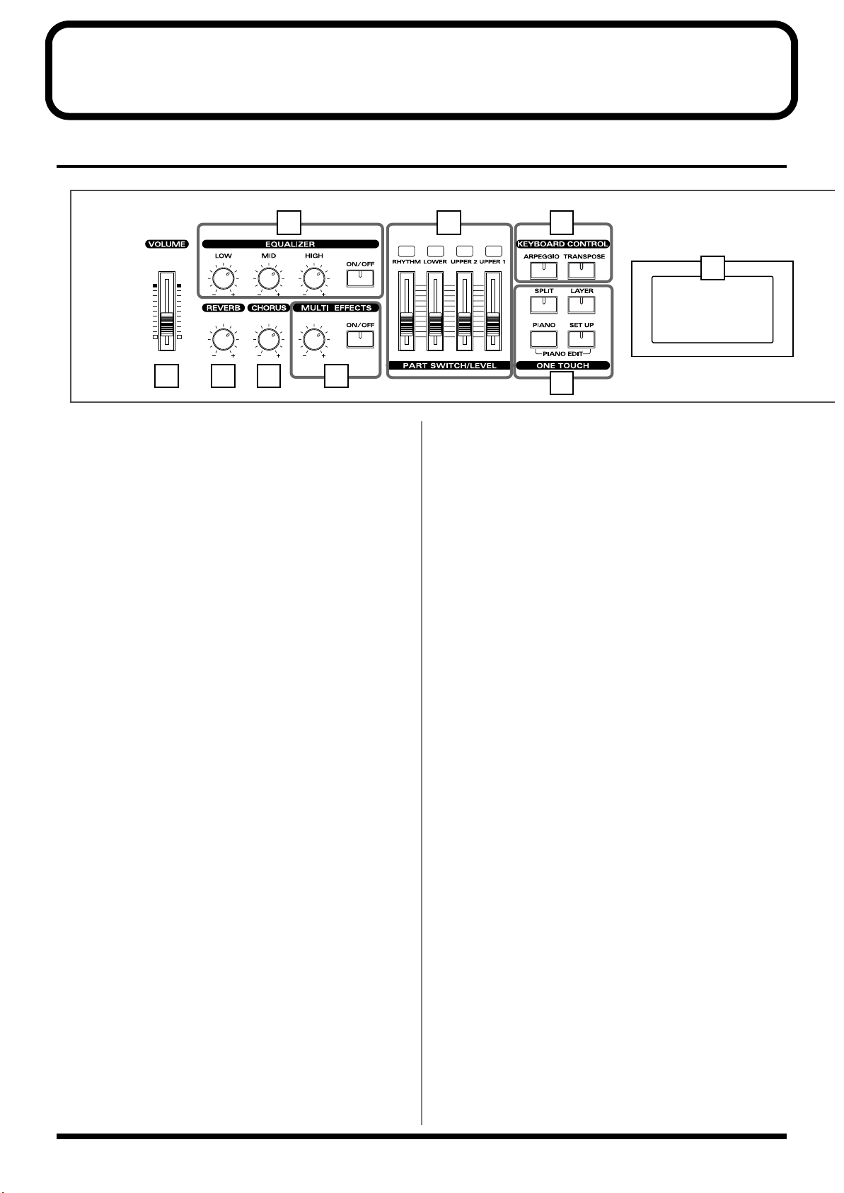
Panel Descriptions
Front Panel
2 6 7
CONTROL
9
1 3 4 5
1 VOLUME Slider
Adjusts the overall volume that is output from the rear panel
OUTPUT jacks and PHONES jack (p. 25).
2 EQUALIZER
[ON/OFF]
Turns the equalizer on/off (p. 48).
[LOW] knob
Adjusts the sound's low-frequency range.
[MID] knob
Adjusts the sound's midrange frequencies.
[HIGH] knob
Adjusts the sound's high-frequency range.
3 REVERB knob
Adjusts the amount of reverb (p. 47).
4 CHORUS knob
Adjusts the amount of chorus (p. 47).
5 MULTI EFFECTS
[CONTROL] knob
Adjusts the way that effects are applied (p. 53).
[ON/OFF]
Switches the multi-effects on/off (p. 53).
8
6 PART SWITCH/LEVEL
Turns each part's sound on and off (PART SWITCH), and
adjusts the volume level for each part (PART LEVEL slider)
(p. 45).
When [MIDI TX] is on, this controls each part for the external
MIDI sound generator (p. 62).
7 KEYBOARD CONTROL
[ARPEGGIO]
Switches Arpeggiator on/off (p. 49).
[TRANSPOSE]
Sets the range of the keyboard to transposed (p. 46).
8 ONE TOUCH
[SPLIT]
Puts the keyboard in “Split mode,” wherein you can use
more than one tone by having different tones play in
different parts of the keyboard (p. 43).
[LAYER]
Puts the keyboard in “Layer mode,” in which the keyboard
plays two tones simultaneously (p. 42).
[PIANO]
Selects the optimum settings for piano performances (p. 35).
[SETUP]
Calls up the stored settings (Setup) (p. 54).
Additionally, pressing [PIANO] and [SETUP]
simultaneously allows you to access more detailed piano
performance settings (PIANO EDIT) (p. 66).
12
Page 13
Panel Descriptions
10
12 13 14
11 15
9 DISPLAY
This shows the Tone names and the values of various
settings, etc (p. 32).
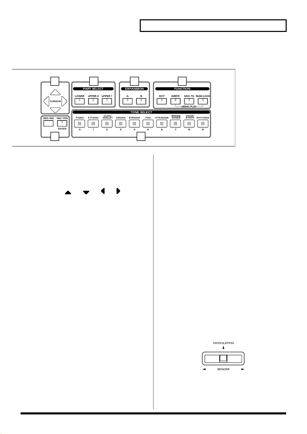
10 CURSOR [ ], [ ], [ ], [ ]
Press these to switch pages and to move the cursor (p. 33).
11 [DEC/NO], [INC/YES]/[ENTER]
This is used to modify values.
If you keep on holding down one button while pressing the
other, the value change accelerates.
Use “ENTER” to finalize a value or execute an operation.
12 PART SELECT buttons
Selects the part for which the tone is to be selected (p. 44).
13 EXPANSION [A], [B]
This selects a sound from a wave expansion board, sold
separately (p. 39).
14 FUNCTION
[EDIT]
Press this button when you wish to adjust various settings
(p. 68).
[WRITE]
Stores the current settings to “Setup” (p. 56).
[MIDI TX]
Puts the RD-700 in control of the external MIDI sound
generator (p. 59).
[NUM LOCK]
You can input numerical values with the TONE SELECT
buttons when this button is lit (p. 37).
In addition, you can listen to the demo songs by
simultaneously pressing this button and [WRITE] (DEMO
PLAY) (p. 34).
15 TONE SELECT buttons
Pressed to select tones (p. 36).
You can also input numerical values with these buttons
when the [NUM LOCK] button is on. [NUM LOCK] turns on
automatically in the Edit and other screens, enabling input of
numerical values with the buttons.
Pitch Bend/Modulation Lever
This allows you to control pitch bend or apply vibrato (p. 48).
13
Page 14
Panel Descriptions
Rear Panel
2
4
1
3
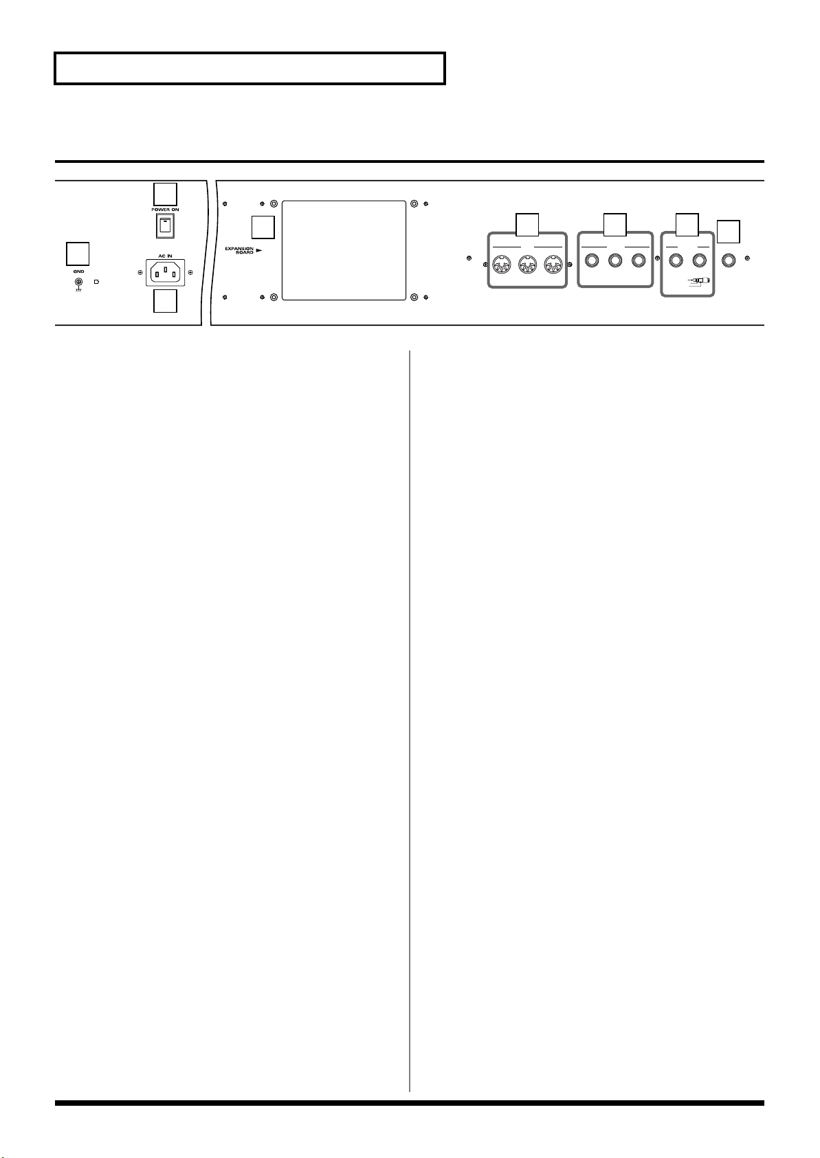
1 GND Terminal
Connect using a grounded cable (optional) as conditions
require.
In some cases, depending on the environment in which the
unit is installed, the surface of the panel may sometimes feel
rough and grainy. This is due to an infinitesimal electrical
charge, which is absolutely harmless. However, if you are
concerned about this, connect the ground terminal with an
external ground. When the unit is grounded, a slight hum
may occur, depending on the particulars of your installation.
If you are unsure of the connection method, contact the
nearest Roland Service Center, or an authorized Roland
distributor, as listed on the “Information” page.
Unsuitable places for connection
- Water pipes (may result in shock or electrocution)
- Gas pipes (may result in fire or explosion)
- Telephone-line ground or lightning rod (may be
dangerous in the event of lightning)
5 6 7
MIDI
THRU OUT IN
PEDAL
FC 1 FC 2DAMPER
OUTPUT
R
BALANCED
TIP
RING
SLEEVE
8
)
L(MONO
PHONES
HOT
COLD
GND
6 PEDAL Jacks (DAMPER, FC1, FC2)
Connecting the pedal switch (DP-6) provided with the RD700 to the DAMPER jack allows you to use the switch as a
damper pedal.
With an optional expression pedal (such as the EV-5 or other
model) connected to the FC-1 or FC-2 jack, you can then
assign a variety of functions to the pedal (p. 23, p. 73).
7 OUTPUT R/L (MONO) Connectors
Provide output of the audio signals. These are connected to
an amp or other device. For monaural output use the L/
MONO jack (p. 22).
These also feature balanced output.
8 PHONES Jack
A set of headphones can be connected to this jack (p. 22).
Even when headphones are connected, sound will still be
output from the output jacks.
2 [POWER] Switch
Switch turns the power on/off (p. 24).
3 AC Inlet
Connect the included power cable to this inlet. (p. 22).
4 Wave Expansion Board Installation
Slot
Remove the cover for installation of optional wave expansion
boards (SRX Series) (p. 15).
5 MIDI Connectors (IN, OUT, THRU)
Used for connecting external MIDI devices and for
transmission of MIDI messages (p. 22, p. 59, p. 95).
14
Page 15

Getting Ready
Installing the Wave Expansion Board
Up to two optional Wave Expansion Boards (SRX Series) can be installed in
the RD-700.
Wave Expansion Boards store Wave data, Patches, and Rhythm Sets, and by
equipping the RD-700 with these boards, you can greatly expand your
sound palette.
Cautions When Installing an Wave Expansion Board
●
To avoid the risk of damage to internal components that can be caused by
static electricity, please carefully observe the following whenever you
handle the board.
• Before you touch the board, always first grasp a metal object (such as
a water pipe), so you are sure that any static electricity you might
have been carrying has been discharged.
• When handling the board, grasp it only by its edges. Avoid touching
any of the electronic components or connectors.
• Save the bag in which the board was originally shipped, and put the
board back into it whenever you need to store or transport it.
●
Use a Philips screwdriver that is suitable for the size of the screw (a
number 2 screwdriver). If an unsuitable screwdriver is used, the head of
the screw may be stripped.
●
To remove a screw, rotate the screwdriver
counter-clockwise. To tighten a screw, rotate
the screwdriver clockwise.
●
Be careful that the screws you remove do not
drop into the interior of the RD-700.
●
Do not leave the rear panel cover removed. After installation of the Wave
Expansion Boards is complete, be sure to replace the cover.
●
Do not touch any of the printed circuit pathways or connection terminals.
●
Be careful not to cut your hand on the edge of the installation bay.
●
Never use excessive force when installing a circuit board. If it doesn’t fit
properly on the first attempt, remove the board and try again.
●
When circuit board installation is complete, double-check your work.
●
Always turn the unit off and unplug the power cord before attempting
installation of the circuit board.
●
Install only the specified circuit board(s) (SRX Series). Remove only the
specified screws.
tightenloosen
Getting Ready
Install the Wave Expansion Boards after removing the rear panel cover.
There are two slots (A and B) into which a board can be installed. Specify
which slot's board is to be used by pressing EXPANSION [A] or [B] on the
front panel when using waves, tones, or Rhythm Sets from the wave
expansion boards.
15
Page 16
Getting Ready
Installing SRX Series Boards
1
2
fig.Q-02.e
Getting Ready
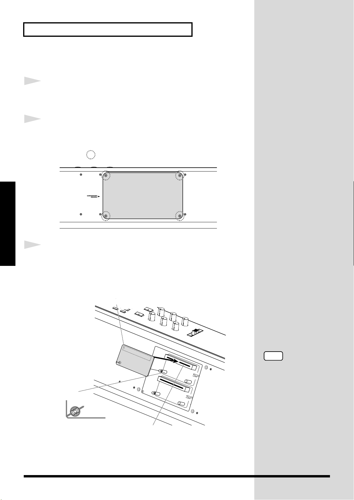
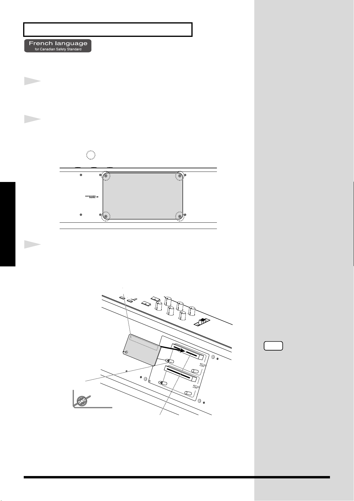
3
Before installing any Wave Expansion Board, turn off the
power on the RD-700 and all devices connected to it.
Refer to the following illustration of the RD-700’s rear panel,
and remove the screws indicated. Then, remove the cover.
Screws to be removed
Insert the Wave Expansion Board connector into a connector
for an SRX Series slot (SRX A or SRX B), while simultaneously
inserting the board holders into the holes in the Wave
Expansion Board.
fig.Q-05.e
Wave Expansion Board (SRX series)
Board holder
Position them as shown
before you install the board.
Connector
NOTE
If the same type of Wave
Expansion Board is
installed in the SRX A slot
and the SRX B slot, it will
only be possible to select
data from the Wave
Expansion Board that was
installed in the SRX A slot.
16
Page 17
Getting Ready
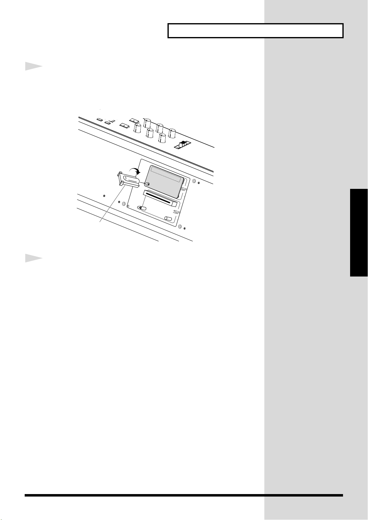
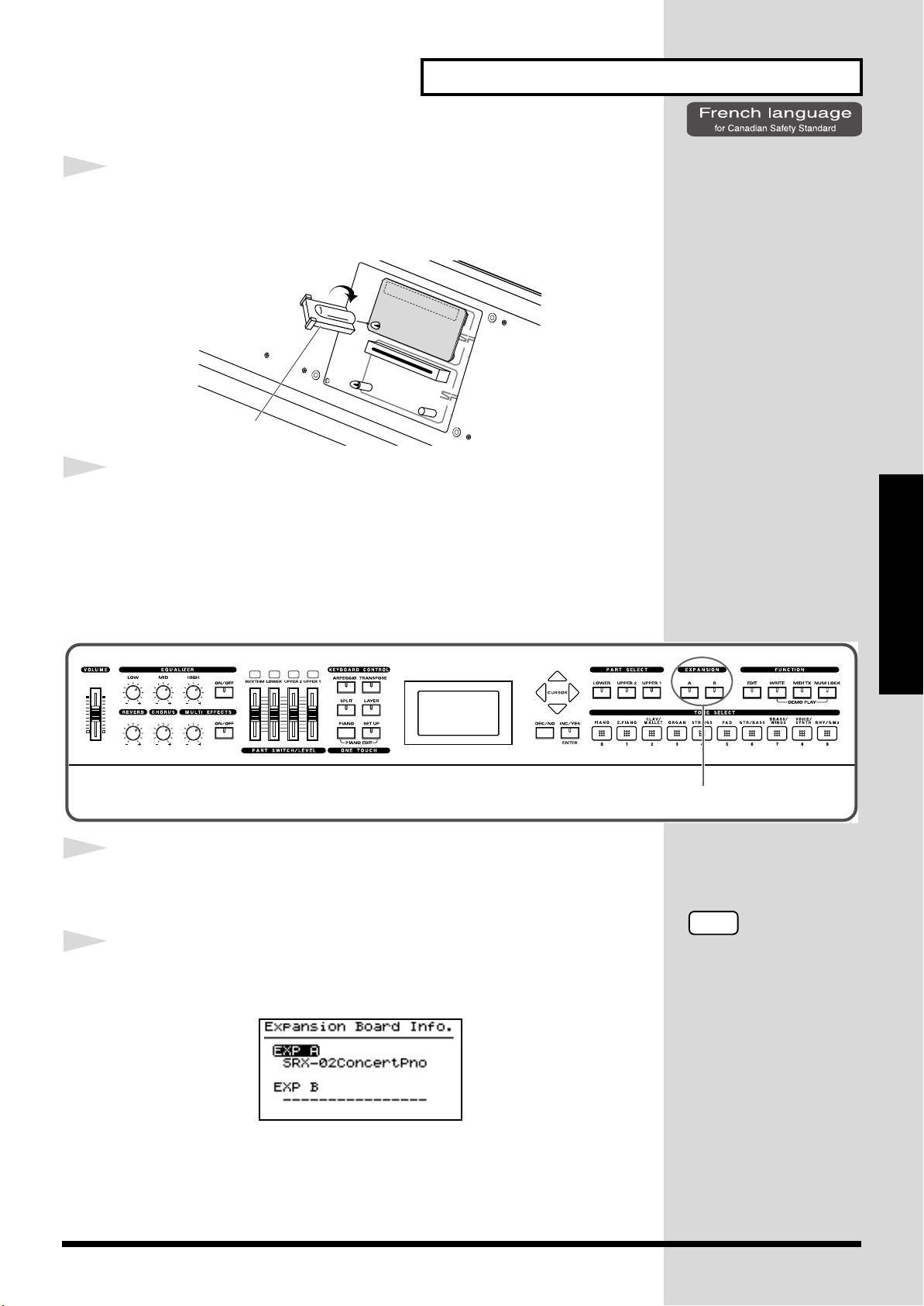
4
Use the Installation Tool supplied with the Wave Expansion
Board to turn the holders in the LOCK direction, so the board
will be fastened in place.
fig.Q-06.e
LOCK
Getting Ready
Installation tool
5
Use the screws that you removed in step 2 to fasten the cover
back in place.
17
Page 18
Getting Ready
NOTE
If “—————-” appears
next to the name of the slot
in which the board was
installed, it may be that the
wave expansion board is
not being recognized
properly. Use the
procedure in “Turning Off
the Power” (p. 25) to turn
the power off, then reinstall
the wave expansion board
correctly.
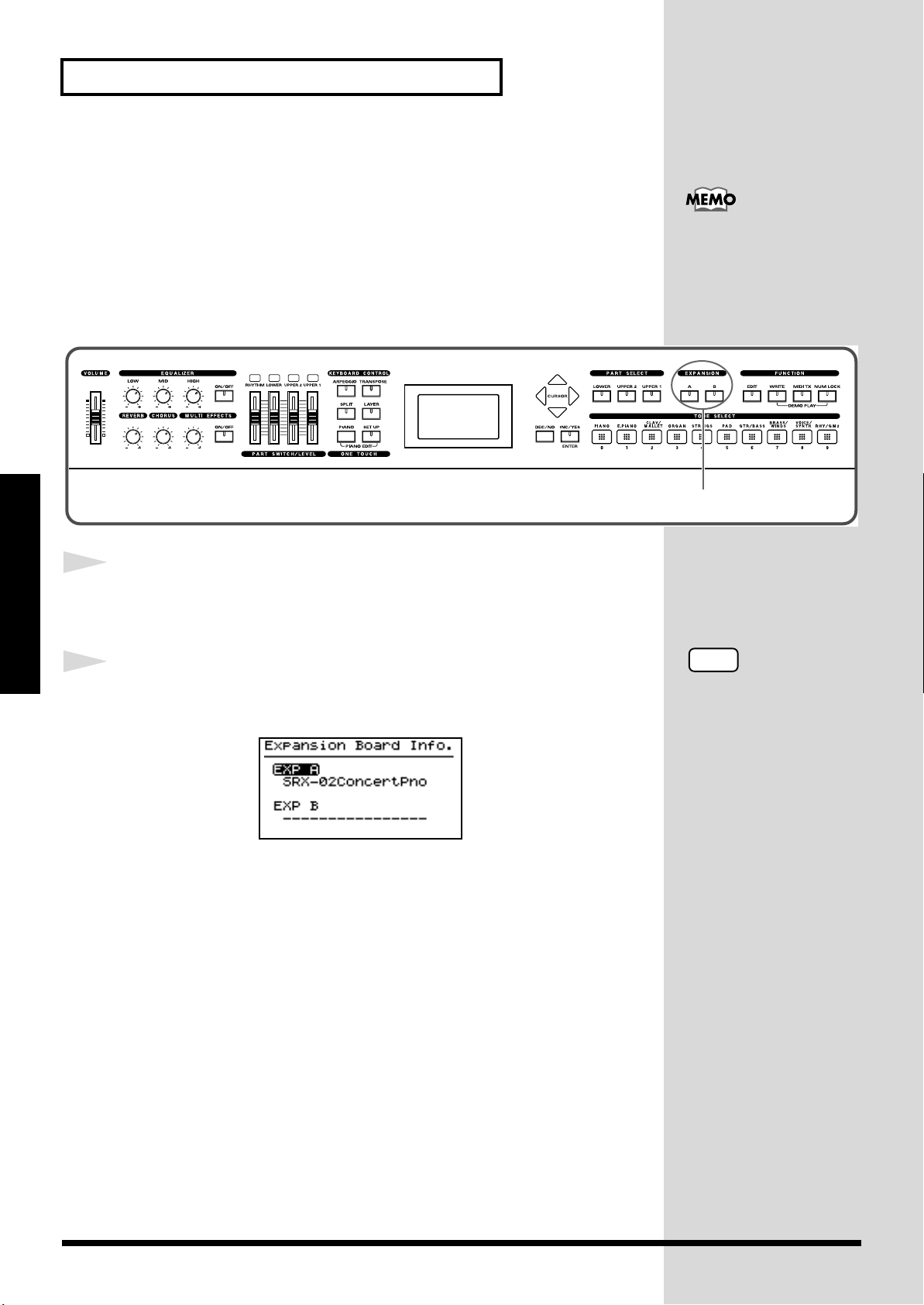
Checking the Installed Wave Expansion Boards
After installation of the Wave Expansion Boards has been completed, check
to confirm that the installed boards are being recognized correctly.
fig.panel
CONTROL
For instructions on
selecting Wave Expansion
Board Tones, refer to
“Selecting Wave
Expansion Board Tones”
2
1
Getting Ready
2
fig.LCD
Turn on the power, as described in
“Turning On the Power”
(p. 24).
Hold down EXPANSION [A] or [B] for several seconds.
The name of the installed wave expansion board appears in the display.
The example here depicts what you would see if the SRX-02 “Concert
Piano” Wave Expansion Board were installed in the SRX A slot.
By releasing the button, you go back to the previous screen.
18
Page 19
Getting Ready
Installation de la carte d’extension Wave
(French language for Canadian Safety Standard)
Vous pouvez installer jusqu’à 2 cartes d’extension optionnelles dans le RD-
700.
Ces cartes d’extension mémorisant des données Wave, des morceaux et des
ensembles rythmiques, elles vous permettront d’augmenter
considérablement le timbre.
Precautions lors de l’installation de la carte d’extension Wave
●
Veuillez suivre attentivement les instructions suivantes quand vous
manipulez la carte afin d’éviter tout risque d’endommagement des pièces
internes par l’électricité statique.
• Toujours toucher un objet métallique relié à la terre (comme un tuyau
par exemple) avant de manipuler la carte pour vous décharger de
l’électricité statique que vous auriez pu accumuler.
• Lorsque vous manipulez la carte, la tenir par les côtés. Évitez de
toucher aux composants ou aux connecteurs.
• Conservez le sachet d’origine dans lequel était la carte lors de l’envoi
et remettez la carte dedans si vous devez la ranger ou la transporter.
●
Utiliser un tournevis cruciforme correspondant à la taille de la vis (un
tournevis numéro 2). En cas d’utilisation d’un tournevis inapproprié, la
tête de la vis pourrait être endommagée.
●
Pour enlever les vis, tourner le tournevis
dans le sens contraire des aiguilles d’une
montre. Pour resserrer, tourner dans le
sens des aiguilles d’une montre.
●
Veillez à ne pas laisser tomber de vis dans le châssis du RD-700.
●
Ne pas laisser la plaque arrière détachée. Après avoir installé la ou les
carte(s) d’extension, bien remettre la plaque en place.
●
Ne pas toucher aux circuits imprimés ou aux connecteurs.
●
Veillez à ne pas vous couper les doitgs sur le bord de l’ouverture
d’installation.
●
Ne jamais forcer lors de l’installation de la carte de circuits imprimés. Si
la carte s’ajuste mal au premier essai, enlevez la carte et recommencez
l’installation.
●
Quand l’installation de la carte de circuits imprimés est terminée,
revérifiez si tout est bien installé.
●
Toujours éteindre et débrancher l’appareil avant de commencer l’installation de
la carte.
●
N’installez que les cartes de circuits imprimes spécifiées (SRX Series). Enlevez
seulement les vis indiquées.
Installer les cartes d’extension après avoir enlevé la plaque arrière.
resserrerdesserrer
Getting Ready
19
Page 20
Getting Ready
Installer les cartes de série SRX
1
2
fig.Q-02.f
Getting Ready
3
Avant d’installer une carte d’extension Wave, éteindre tous les
appareils reliés au RD-700.
Détacher la plaque arrière en enlevant les vis indiquées sur le
schéma suivant.
Vis à enlever
Insérer le connecteur de la carte dans un des créneaux pour la
série SRX (SRX A, SRX B) tout en enfonçant les supports à
carte dans les trous de celle-ci.
fig.Q-05.f
Carte d'extension Wave (serie SRX)
Support à carte
Avant l’installation, orienter les supports
à carte tel qu’indiqué sur le schéma.
Connecteur
NOTE
Si la même sorte de carte
d’extension Wave est
installée dans les créneaux
SRX A et SRX B, il ne sera
possible de sélectionner
que les données de la carte
d’extension Wave installée
dans le créneau SRX A.
20
Page 21
Getting Ready
CONTROL
2
4
Pour tourner les supports en position LOCK (verrouillé),
utilisez l’outil d’installation de la carte d’extension fournie à
cet effet. De cette façon, la carte sera bien fixée à sa place.
fig.Q-06.f
LOCK
Outil d'installation
5
Reposez le couvercle en remettant les vis enlevées (comme
spécifié) à l’étape 2.
Vérification des cartes d’extension audio aprés installation
Lorsque l’installation des cartes d’extension audio est terminée, procéder à
une vérification pour s’assurer que l’ordinateur les identifie correctement.
fig.Q-07
Getting Ready
1
2
Mettre sous tension de la façon décrite sous
Power”
(p. 24).
“Turning On the
Tenez EXPANSION [A] ou [B] enfoncé pendant plusieurs
secondes.
fig.LCD
L’exemple montre ce qui serait affiché si la carte d’extension audio SRX-02
“Concert Piano“était installée dans la fente SRX A.
Lorsque vous le relâcherez, vous serez ramené à l'écran précédent.
NOTE
Si “----------------“ est affiché
à côté du nom de la fente
dans laquelle la carte est
installée, il est possible que
la carte d’extension audio
installée ne soit pas
reconnue correctement.
Mettre hors tension de la
façon décrite sous
“Turning Off the Power”
(p. 25) et réinstaller
correctement la carte
d’extension audio.
21
Page 22
Getting Ready
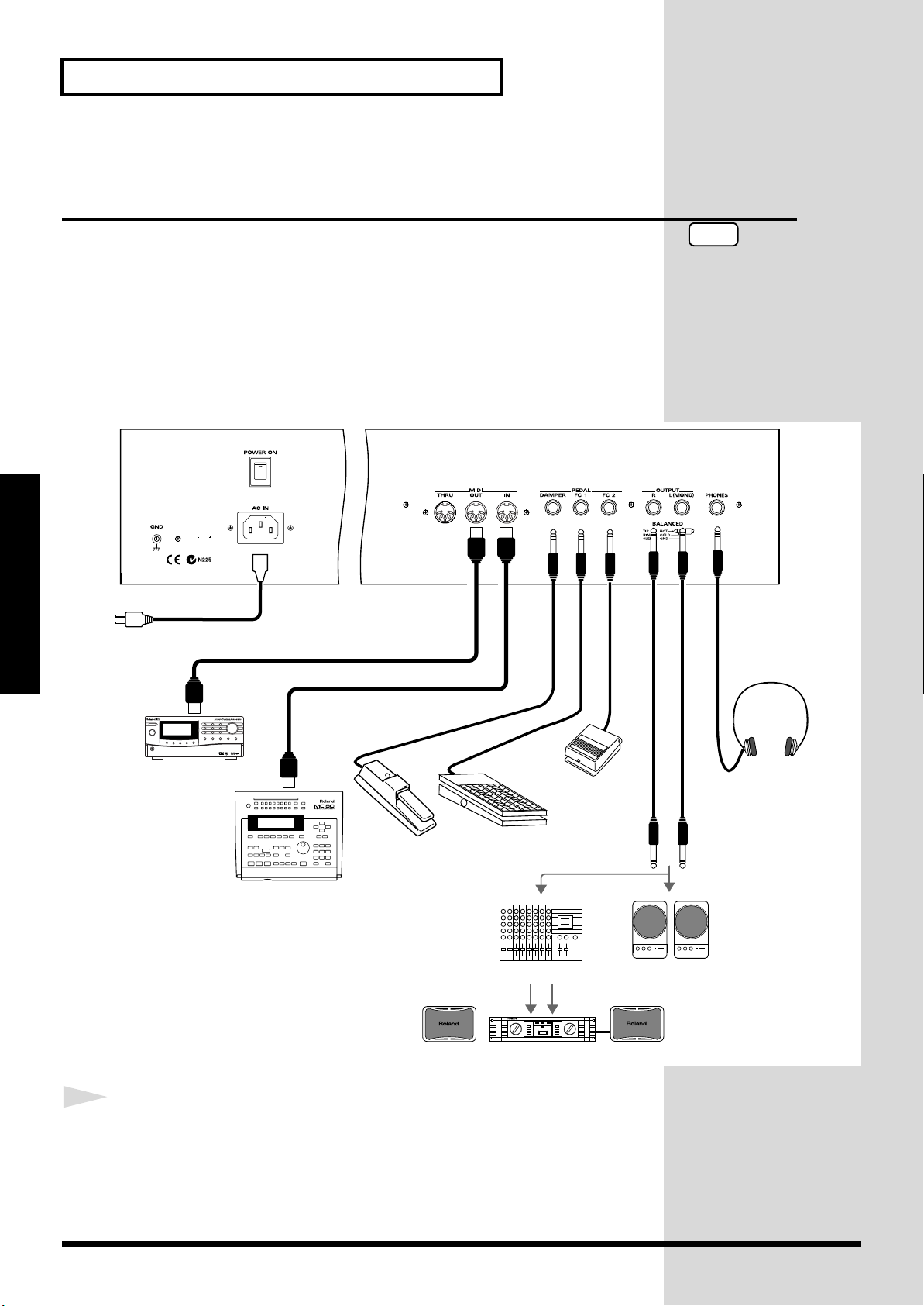
Stereo
headphones
Monitor speakers
(powered)
Power amp.
Mixer etc.
MIDI IN
MIDI sound module etc.
MIDI OUT
MIDI sequencer etc.
to Power outlet
Expression pedal (EV-5)
or Pedal switch
Pedal switch
(DP-2, DP-6 etc.)
Roland
Connecting the RD-700 to External Equipment
* Audio cables, MIDI cables, headphones, and expression pedals are not included.
fig.00-05.e
Getting Ready
The RD-700 is not equipped with an amplifier or speakers. In order to
produce sound, you need to hook up audio equipment such as a monitor
speaker or a stereo set, or use headphones.
Consult your Roland dealer if you need to purchase accessories such as these.
NOTE
To prevent malfunction
and/or damage to speakers
or other devices, always
turn down the volume, and
turn off the power on all
devices before making any
connections.
1
Before you begin making connections, confirm the following.
Is the volume level of the RD-700 or connected amp turned all the way
down?
Is the power to the RD-700 or connected amp turned off?
22
Page 23
Getting Ready
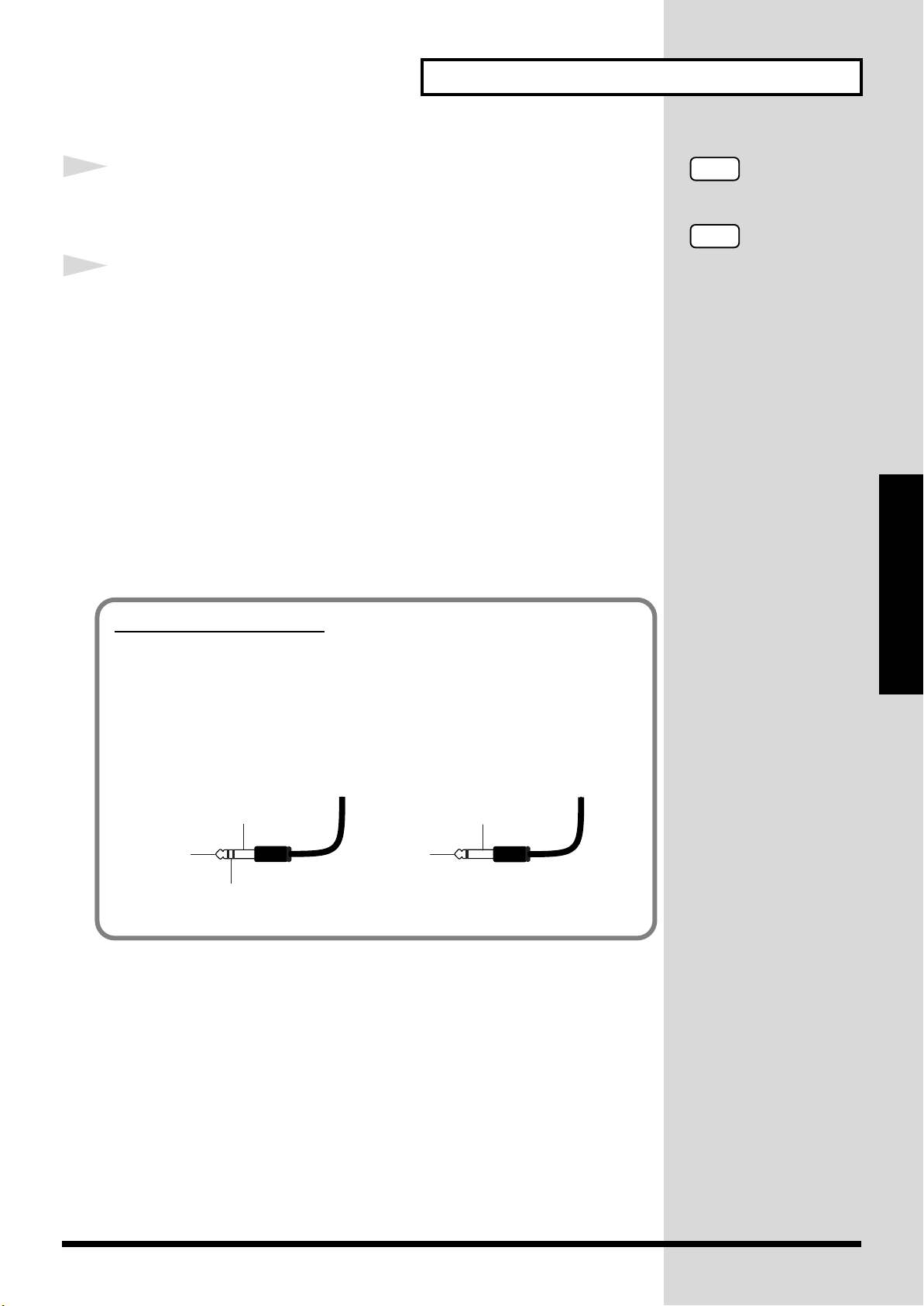
About the Output Jacks
The RD-700’s output jacks are capable of use with either balanced or
unbalanced output.
To use balanced output, use a cable with a balanced (TRS type) phone plug.
To use unbalance output, use a cable with an unbalanced (TS type) phone
plug.
2
Connect supplied AC power cable to the RD-700, and plug the
other end into an AC power outlet.
3
Connect the RD-700 and the external device.
Use audio cables to connect audio equipment, such as an amp or speakers.
Use MIDI cables to connect MIDI devices.
If you are using headphones, plug them into the PHONES jack.
Connect pedal switches or expression pedals as necessary.
Connecting Pedals
Connect the pedal included with the RD-700 to one of the Pedal jacks.
When connected to the Damper jack, the pedal can be used as a damper
pedal.
Connecting the pedal to the FC-1 or FC-2 jack allows you to assign a variety
of functions to the pedal (p. 73).
NOTE
Use Stereo headphones.
NOTE
Use only the specified
expression pedal (EV-5;
sold separately). By
connecting any other
expression pedal, you risk
causing malfunction and/
or damage to the unit.
Getting Ready
fig.TRS
TRS TS
TIP (Hot)
SLEEVE (Ground)
TIP (Hot)
RING (Cold)
SLEEVE (Ground)
23
Page 24
Getting Ready
b
NOTE
To prevent incorrect
functioning of the Pitch
Bend Lever (p. 48), refrain
from touching the lever
while the power to the RD700 is turned on.
Turning the Power On and Off
Once the connections have been completed, turn on power to your various
devices in the order specified. By turning on devices in the wrong order, you
risk causing malfunction and/or damage to speakers and other devices.
Turning On the Power
1
fig.00-06
Getting Ready
2
fig.00-07
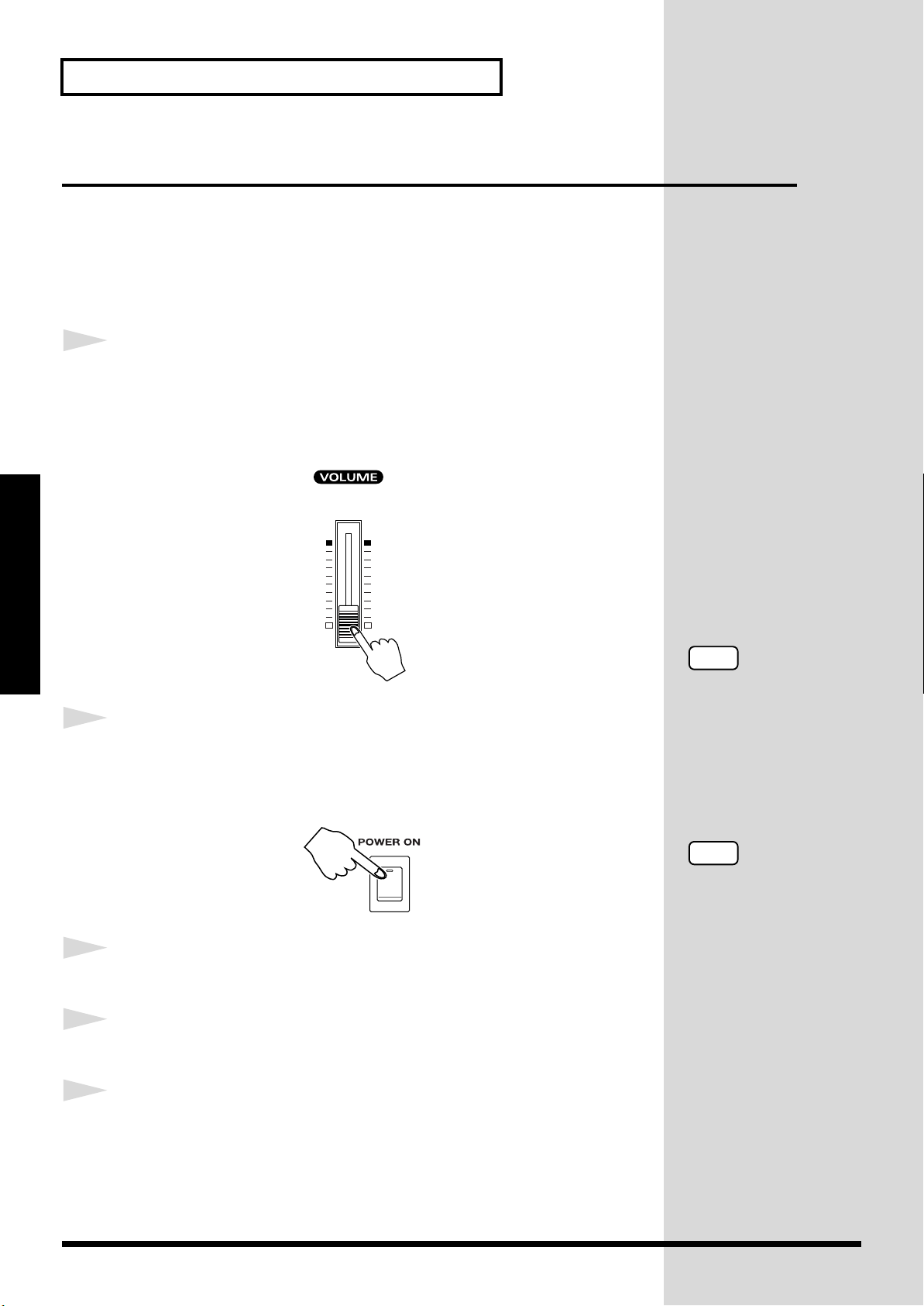
Before you switch on the power, turn the volume down all the
way by rotating the VOLUME Slider.
Also completely turn down the volume of any connected audio device and
other equipment.
Press the upper portion of the [POWER] switch to turn on the
power.
The unit is powered up, and the display's backlighting comes on.
3
4
5
24
Turn on the power to connected external devices.
Adjust the volume of the connected external device.
Adjust the RD-700’s volume to obtain the proper volume level.
NOTE
This unit is equipped with
a protection circuit. A brief
interval (a few seconds)
after power up is required
efore the unit will operate
normally.
Page 25
Turning Off the Power
Getting Ready
1
2
3
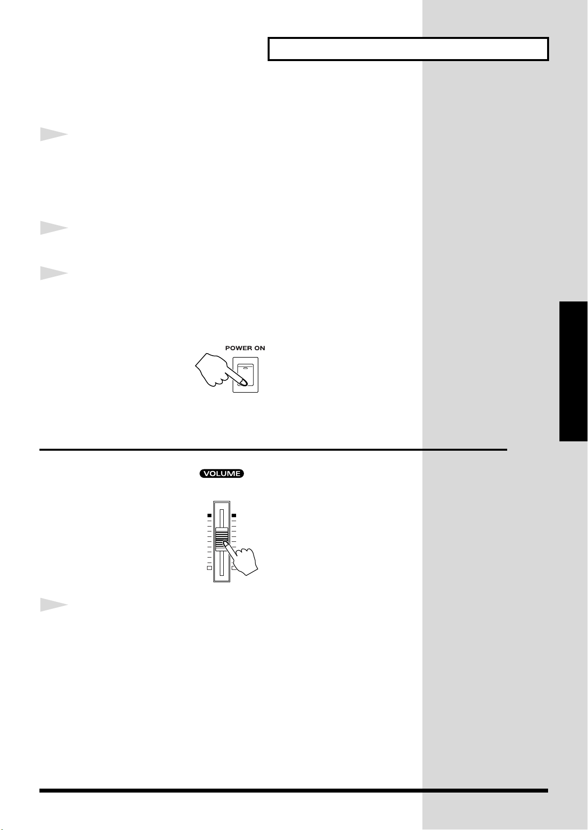
Before you switch on the power, turn the volume down all the
way by rotating the VOLUME Slider.
Also completely turn down the volume of any connected audio device and
other equipment.
Turn off the power to connected external devices.
Press the lower portion of the [POWER] switch on the back of
the RD-700.
The power is switched off.
fig.00-07
Getting Ready
Adjusting the Volume
fig.00-08
1
Adjust the volume using the VOLUME slider.
Move the slider up to increase the volume, or down to lower it.
Also adjust the volume of the connected device to an appropriate level.
25
Page 26
Getting Ready
Restoring the Factory Settings (Factory Reset)
Notes
Getting Ready
fig.panel
When using the RD-700 for the first time, start by returning the settings to
their factory defaults so that the RD-700 operates as described in the
procedures in the owner’s manual.
Never turn off the power during Factory Reset (while “Now,
Executing” appears in the display).
Turning off the power while Factory Reset is in progress may result in
corrupted internal data and may prevent the power from being turned on
again. If you have confirmed that the internal data has been lost, or if a
similar problem exists, consult the retailer from whom you purchased the
instrument, or the nearest Roland Service Center. Note, however, that
Roland assumes no liability, including compensation, for consequences
arising from any loss of data.
NOTE
Executing this operation
deletes the Setup settings
(p. 54). If you want to keep
any internally stored
content, use the “Bulk
Dump (Bulk Dump
SETUP)” procedure to save
the data to an external
sequencer (p. 92).
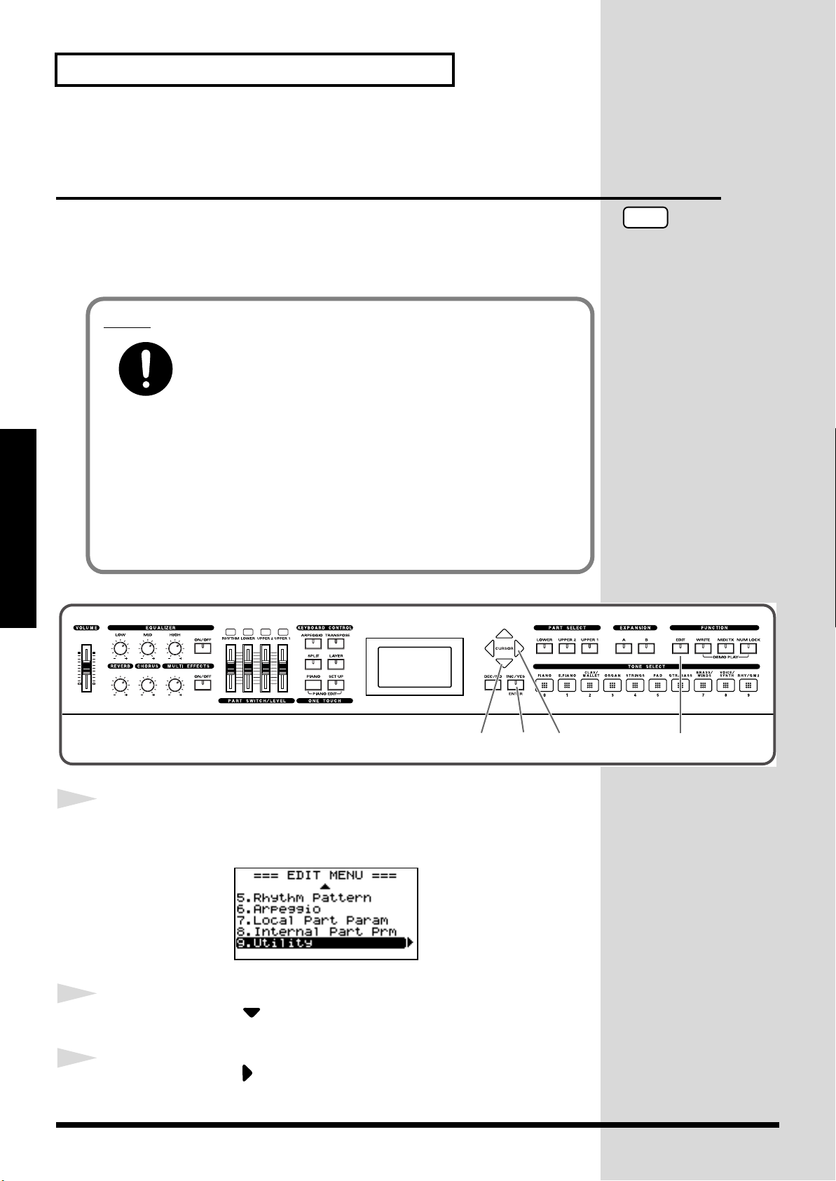
1
2
3
CONTROL
12,4 6,7 3,5
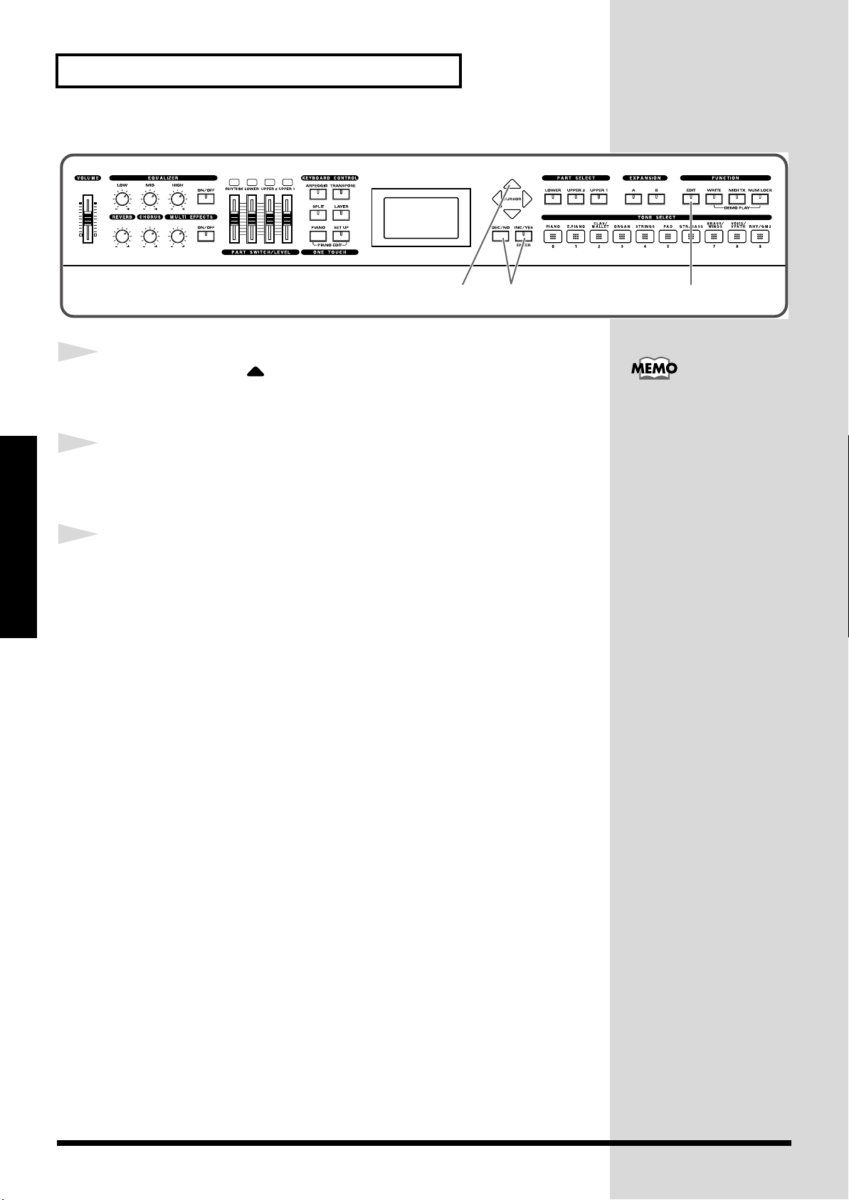
Press [EDIT], getting the indicator to light.
The Edit Menu screen appears.
fig.Editmenu2.eps_150
Press CURSOR [ ] to select “9.Utility.”
Press CURSOR [ ] to display the Edit screen.
26
Page 27
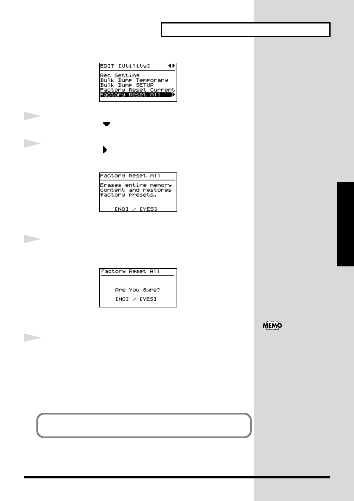
fig.utility1.eps_150
Getting Ready
4
5
6
Press CURSOR [ ] to select “Factory Reset All.”
Press CURSOR [ ].
A screen like the one shown below appears.
fig.utility1.eps_150
Getting Ready
To cancel the Factory Reset, press [DEC/NO].
Press [INC/YES].
The confirmation message appears.
fig.LCD_150
7
To cancel the Factory Reset, press [DEC/NO].
Press [INC/YES] once again to start the Factory Reset
operation.
During the execution, “Now, Executing” appears in the display.
After the Factory Reset operation is finished, the display will indicate
“COMPLETED” and the Tone screen will appear.
You can also restore only part of the setting to their factory status. Refer to
“Restoring the settings to the factory condition (Factory Reset)” (p. 94).
After performing a Factory
Reset, you may need to readjust the display contrast.
When this occur, adjust
depth of the display (p. 28).
27
Page 28
Getting Ready
Adjusting the Display Contrast (LCD Contrast)
The characters in the display may be difficult to view immediately after
turning on the power or after extended use; this may also be because of
where and how the display is situated. Follow the steps below to adjust the
display’s contrast.
fig.panel
CONTROL
The LCD CONTRAST
setting affects the RD-700
as a whole (i.e., is a system
setting). This setting
remains stored in memory
even while the power is off.
1
Getting Ready
fig.Editmenu1.eps_150
2
3
fig.system1.eps_150
1,62,4 5 3
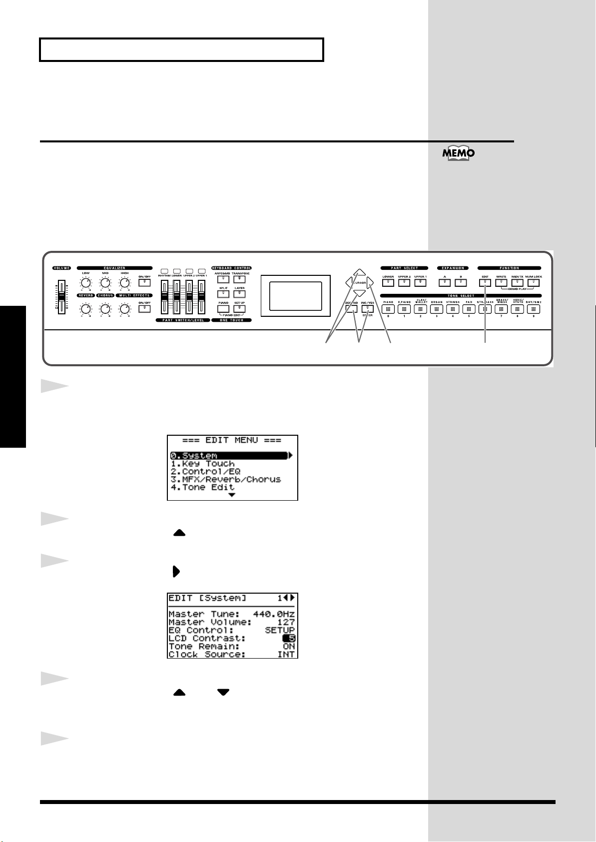
Press [EDIT], getting the indicator to light.
The Edit Menu screen appears.
Press CURSOR [ ] to select “0.System.”
Press CURSOR [ ] to display the Edit screen.
4
5
28
Press CURSOR [ ] or [ ] to move the cursor to the “LCD
Contrast” parameter.
Press [INC/YES] or [DEC/NO] to select the value (1–10).
The brightness of the display changes as the value is changed. Adjust the
contrast so that the display is easy to view.
Page 29
Getting Ready
CONTROL
12 3
6
Press [EDIT] to make the indicator go dark.
You are returned to the Tone screen.
Tuning to Other Instruments’ Pitches (Master Tune)
For a cleaner ensemble sound while performing with one or more other
instruments, ensure that each instrument’s basic pitch is in tune with that of
the other instruments. In general, the tuning of an instrument is indicated
by the pitch in Hertz (Hz) of the middle “A” note.
This matching of other instruments’ basic reference pitches is called
“tuning.”
fig.panel
The Master Tune setting is
a system setting that is
applied to the entire RD700 (i.e., is a system
setting), This setting
remains stored in memory
even while the power is off.
Getting Ready
1
2
3
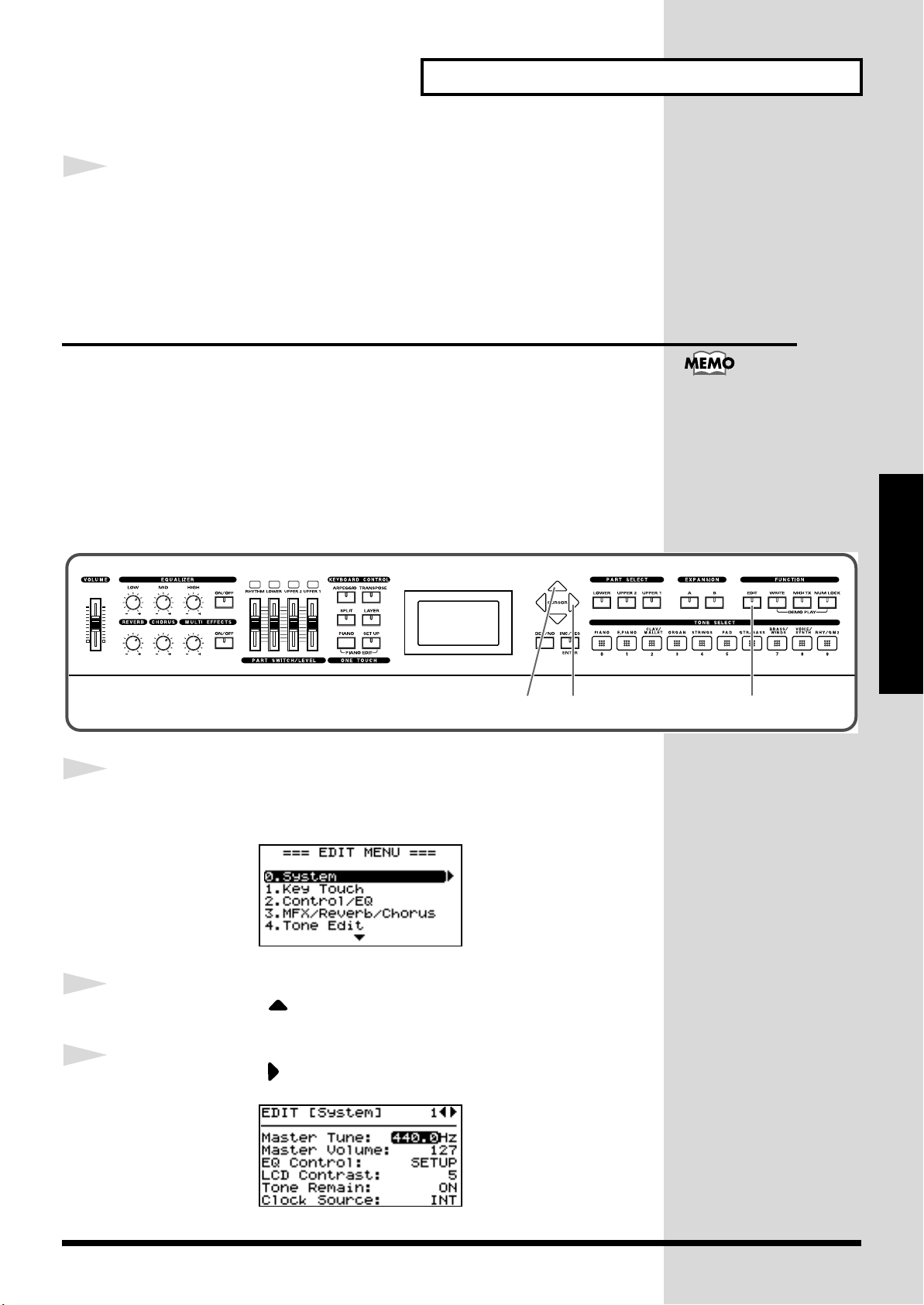
Press [EDIT], getting the indicator to light.
The Edit Menu screen appears.
fig.Editmenu1.eps_150
Press CURSOR [ ] to select “0.System.”
Press CURSOR [ ] to display the Edit screen.
fig.system1.eps_150
29
Page 30
Getting Ready
CONTROL
645
4
5
6
Getting Ready
Press CURSOR [ ] to move the cursor to the “Master Tune”
parameter.
Press [INC/YES] or [DEC/NO] to select the value (415.3–
440.0–466.2).
Press [EDIT] to make the indicator go dark.
You are returned to the Tone screen.
For faster value increases,
keep [INC/YES] pressed
down and press [DEC/
NO]. For decreasing value
faster, keep [DEC/NO]
pressed down and press
[INC/YES].
30
Page 31

Overview of the RD-700
Basic Organization of the RD-700
The RD-700 can be divided into two sections: a keyboard
controller section and a sound generator section. The two
sections are connected internally by means of MIDI.
fig.00-G1
Sound
Generator
Section
Play
Keyboard Controller Section
(controllers such as keyboard, pitch bend lever, etc.)
Keyboard Controller Section
This section includes the keyboard, the Pitch Bend/
Modulation Lever, the panel knobs, and any pedal connected
to the rear panel. Actions such as pressing and releasing of
keys on the keyboard, depressing a pedal, and so forth, are
converted to MIDI messages and sent to the sound generator
section, or to an external MIDI device.
Sound Generator Section
The sound generator section produces the sound. Here, MIDI
messages received from the keyboard controller section or
external MIDI device are converted to musical signals, which
are then output as analog signals from the OUTPUT and
PHONES jacks.
Units of Sound
When using the RD-700, you will notice that a variety of
different categories come into play when working with
sounds. What follows is a simple explanation of each sound
category.
Tone
The individual sounds used when playing the RD-700 are
referred to as “Tones.” The RD-700 provides 468 types of
Tones. Tones are assigned to each part.
The Tones also include various groups of percussion
instrument assembled into “Rhythm Sets.” Each key (note
number) of a Rhythm Set will produce a different percussion
instrument.
Part
A sound generator of this type which can control multiple
sounds using one device is referred to as a multitimbral
sound generator. The RD-700 contains a multitimbral sound
generator capable of playing sixteen Tones simultaneously.
“Parts” are where Tones that are created when the RD-700 is
used as a sound generator are assigned. Since different Tones
can be assigned to each of the Parts and controlled
individually, you can have multiple Tones play
simultaneously (layer), divide the keyboard into separate
ranges and have different Tones sound in the different parts
(Split), and enjoy playing ensemble performances.
The sixteen Parts played by the RD-700’s internal sound
generator are referred to as “Internal Parts.”
Overview of the RD-700
Local Parts and MIDI TX Parts
The RD-700 features three Parts (UPPER1, UPPER2, and
LOWER) that you can use for freely controlling the Internal
Parts with the RD-700’s buttons and keyboard. These three
Parts that are used for controlling the Internal Parts are
collectively known as the “Local Parts.” Three of the sixteen
Internal Parts are assigned to the Local Parts for control (the
RHYTHM Part is fixed at Part 10).
Furthermore, you can freely control external MIDI sound
generators with the RD-700 in the same manner as with the
Local Parts. You can likewise control the external MIDI
sound generator with the three Parts (UPPER1, UPPER2, and
LOWER), with this group of three Parts being referred to as
the “MIDI TX (Transmit) Parts.” The external MIDI sound
generator is assigned to these three Parts for control (the
RHYTHM Part can also be partially set).
31
Page 32

Overview of the RD-700
Basic Operation of the RD-700
Main Screens
The Tone Screen (Basic Screen)
The names of the Tones currently selected for the Local Parts
are displayed. This is the screen that is ordinarily displayed.
When ONE TOUCH [PIANO] is pressed, setting the RD-700
to the optimal status for piano performances, this screen is
displayed.
You can change the Local Part UPPER1, UPPER2, and
LOWER Tones and tempo.
fig.00-G2
The Tone Wheel Screen
In the Tone screen, when any ORGAN Tone “Tone Wheel 1–
10” is selected for any of the Local Parts, this screen is
The Rhythm/Arpeggio Screen
Pressing CURSOR [ ] when the Tone screen is displayed
switches the RD-700 to this screen.
You can change Rhythm patterns, Arpeggio patterns, and the
tempo.
Pressing CURSOR [ ] when this screen is displayed
returns you to the Tone screen.
fig.00-G4
Special Indications
When the contents of a Setup (p. 54) are changed, an
asterisk (a “*” mark) appears on the right of the
Setup number. If you want to use the changed
content as a new Setup, save the settings to a Setup
(p. 56).
displayed when CURSOR [ ] is pressed. The mode when
this screen is displayed is called “Tone Wheel mode,” and
Overview of the RD-700
while in this mode you can simulate the creation of sounds
using an organ’s harmonic bars.
Pressing CURSOR [ ] when this screen is displayed
returns you to the Tone screen.
fig.00-G3
The Setup Screen
The currently selected Setup is displayed.
Pressing CURSOR [ ] when the Tone screen or Tone Wheel
Screen is displayed switches the RD-700 to this screen. You
can also have this screen displayed by pressing [SETUP]. You
can change the Setups.
Pressing CURSOR [ ] when this screen is displayed
returns you to the Tone screen or Tone Wheel Screen.
fig.00-G5
With Clock Source (p. 70) set to MIDI, the tempo
indication changes to “M:” for each screen.
The tempo can be changed with the external MIDI
devices when this mark is indicated.
With EQ Control (p. 70) set to SYSTEM, this mark
appears on the screen.
Equalizer settings do not change when Setups are
switched while this mark is indicated.
With Rhythm Type (p. 82) set to “2,” this mark
appears on the screen.
About the Function Buttons
fig.00-G6
[EDIT]
By pressing [EDIT] to make the indicator light, you can enter
“Edit mode.” In Edit mode you can make detailed settings
for various functions.
You can exit Edit mode by pressing [EDIT], extinguishing its
indicator. When exiting from Edit mode, [EDIT]’s indicator
goes out.
32
Page 33

Overview of the RD-700
[WRITE]
Stores the current settings to “Setup”
[MIDI TX]
When [MIDI TX] is pressed, the button’s indicator lights up,
and the RD-700 switches to the mode enabling it to control an
external MIDI sound generator. The status of this button
determines whether the RD-700’s buttons are used to control
the Local Parts ([MIDI TX] off), or to control the MIDI TX
Parts ([MIDI TX] on).
In addition, you can make detailed settings for the MIDI
messages to be transmitted to the external sound generator.
[NUM LOCK]
When [NUM LOCK] is pressed, the button’s indicator lights
up, enabling input of numerical values using the TONE
SELECT buttons. The button indicators automatically light
according to the values set.
About the CURSOR Buttons
ig.00-G7
Additionally, when multiple parameters are presented
horizontally in a row, as shown in the MIDI TX screen, you
can get the cursor to move more rapidly by holding down
the CURSOR button that points in the direction you want the
cursor to move while you also press the CURSOR button that
points in the opposite direction.
fig.00-G10
Changing the Settings Values
fig.00-G11
Overview of the RD-700
The CURSOR buttons are used for switching screens, and for
moving to an item whose setting you want to change (by
moving the cursor).
Moving Between Display Pages
When arrow symbols (“ ” and “ ”) appear at the upper right
of the display screen, it indicates that there are additional
pages in the directions shown by the arrows.
You can switch screens with CURSOR [ ] and [ ].
fig.00-G8
Navigating Among Items To Be Set (CURSOR)
When more than one parameter is present in a screen, the
name and value of the parameter to be changed is shown
with a box around it. This box is referred to as the “cursor.”
The cursor is moved with the CURSOR buttons.
fig.00-G9
Cursor
When changing settings values, you can use [DEC/NO] and
[INC/YES], or the TONE SELECT buttons (numeric keys).
[DEC/NO], [INC/YES]
Pressing [INC/YES] increases the value, and [DEC/NO]
decreases it. Keep the button pressed for continuous
adjustment. For faster value increases, keep [INC/YES]
pressed down and press [DEC/NO]. For decreasing value
faster, keep [DEC/NO] pressed down and press [INC/YES].
TONE SELECT Buttons (Numeric Keys)
When [NUM LOCK] is on (lit), numerical values can be input
directly using the TONE SELECT buttons, which then serve
as [0]–[9] numeric keys. When you enter the number, the
value will blink. This indicates that the value has not yet
been finalized. To finalize the value press [ENTER].
With some parameters, [NUM LOCK] may come on
automatically, allowing you to input numerical values
directly with the TONE SELECT buttons.
The negative (-) or positive (+) sign of numerical values are
switched with [DEC/NO] or [INC/YES].
33
Page 34

Listening to the Demo (DEMO PLAY)
No data for the music that
is played will be output
from the MIDI OUT
connector.
Here’s how to listen to these songs.
The RD-700 features the internal demo songs that exhibit the special
capabilities of the instrument.
1
No. Song Name Composer/Copyright
01. RD Party Scott Wilkie © 2001 Roland Corporation
02. Retro-Active Igor Len © 2001 Roland Corporation
03. Escape Scott Tibbs © 2001 Roland Corporation
04. High-End Speak Scott Tibbs © 2001 Roland Corporation
05. No me digas Scott Tibbs © 2001 Roland Corporation
06. Pastorale Igor Len © 2001 Roland Corporation
fig.panel
CONTROL
Hold down [NUM LOCK] and press [WRITE].
The Demo screen appears.
fig.LCD
NOTE
All rights reserved.
Unauthorized use of this
material for purposes other
than private, personal
enjoyment is a violation of
applicable laws.
12 34,5
NOTE
2
Press CURSOR [ ] / [ ] to select the song that you wish to
hear.
When CHAIN PLAY is selected, the entire group of songs is played back
Listening to the Demo
repeatedly.
3
Press CURSOR [ ] or [INC/YES] to start playback of the
demo song.
When the end of the selected the song is reached, playback then repeats
from the beginning of the song.
4
Press CURSOR [ ] or [DEC/NO] to stop a song during
playback.
5
Press [DEC/NO] while the song is stopped to finish with the
Demo screen.
34
You are returned to the Tone screen.
NOTE
While the demo songs are
playing back, playing the
keyboard will not produce
sound.
When ONE TOUCH
[PIANO] or [SETUP] is
pressed, the song is
stopped, and the Tone
screen or Setup screen
appears in the display.
Page 35

Performing with the Keyboard
When ONE TOUCH
[PIANO] is pressed, all
settings other than the
Piano Edit settings (p. 66)
are switched to their status
at the time the RD-700’s
power was turned on
Store any arrangements of
settings that you want to
keep in Setup (p. 56).
Piano Performances (One Touch [Piano])
Now, try performing with the piano.
With the RD-700, you can call up the optimal settings for piano
performances with the press of a single button.
fig.panel
CONTROL
1
1
Press ONE TOUCH [PIANO].
fig.LCD
The performance setting (Single Mode ➔ p. 41) is selected as the piano tone
for the entire keyboard.
With the RD-700, you can also make more detailed settings to make the
sound even better match your favorite piano performances. Please refer to
each as needed.
• Fine Adjustment of Piano Tones (Piano Edit) ➔ p. 66
• Fine Adjustment of the Piano Touch Sense ➔ p. 71
Performing
35
Page 36

Performing with the Keyboard
When changing tones in
Layer mode (p. 42) or Split
mode (p. 43), select the part
for which the tone is to be
changed with the PART
SELECT buttons, without
pressing the ONE TOUCH
[PIANO] button. For
details, refer to
“Changing
Tones in Layer and Split
Mode” (p. 44).
Performing with a Variety of Tones
The RD-700 provides 468 types of Tones.
Each one of these individual sounds is called a tone.
1
2
Tones are assigned to the TONE SELECT buttons according to the tone
category selected.
Try selecting and performing with a number of different tones.
fig.panel
CONTROL
132,4
Press ONE TOUCH [PIANO].
This selects a single tone to be played over the entire keyboard.
Press any of the TONE SELECT buttons to select the tone
For more on the RD-700’s
internal tones, refer to the
“Tone List” (p. 135).
category.
3
Press [INC/YES] or [DEC/NO] to select the tone.
Performing
The TONE SELECT button for the selected category flashes.
4
Either press the flashing TONE SELECT button or play the
keyboard.
The TONE SELECT button stops flashing and remains lit, and the selected
tone is set.
Play the keyboard, and you will hear the selected tone.
36
The next time you choose this TONE SELECT button, the tone you’re
selected here is played.
NOTE
If [NUM LOCK] is turned
on, the Tone Category
cannot be selected with
TONE SELECT button.
For details, refer to p. 37.
NOTE
Tones selected with [RHY/
GM2] are registered in the
following order: “Rhythm
Sets,” “GM2 Rhythm Sets,”
and “GM2 Tones.” Refer to
the “Tone List” (p. 135).
Page 37

Performing with the Keyboard
When changing tones in
Layer mode (p. 42) or Split
mode (p. 43), select the part
for which the tone is to be
changed with the PART
SELECT buttons, without
pressing the ONE TOUCH
[PIANO] button. For
details, refer to
“Changing
Tones in Layer and Split
Mode” (p. 44).
Specifying the Tone Number to Select a Tone ([NUM LOCK])
Each individual tone has a different tone number.
You can select tones with the TONE SELECT buttons by inputting numerals
with these buttons to specify tone numbers.
Turn [NUM LOCK] on when inputting numerals with the TONE SELECT
buttons.
fig.panel
CONTROL
For more on the RD-700’s
internal tones, refer to the
“Tone List” (p. 135).
1
2
3
4
143 2
Press ONE TOUCH [PIANO].
This selects a single tone to be played over the entire keyboard.
Press [NUM LOCK] to make the indicator light.
This enables input of numerals with the TONE SELECT buttons.
The numerical value that can be entered with each button is indicated
beneath the buttons.
Enter the tone number with the TONE SELECT buttons.
The screen Tone name flashes.
Press [ENTER].
Performing
The tone is set.
Play the keyboard, and you will hear the selected tone.
When [NUM LOCK] is turned off, the TONE SELECT buttons included in
the selected Tone numbers lit.
37
Page 38

Performing with the Keyboard
Tones selected with [RHY/
GM2] are registered in the
following order: “Rhythm
Sets,” “GM2 Rhythm Sets,”
and “GM2 Tones.” Refer to
the
“Tone List” (p. 135).
Playing a Rhythm Set
Among the tones that can be selected with the TONE SELECT buttons are
Rhythm Sets, which are collections of a variety of percussion instrument
sounds and special sound effects. Here’s how to select a Rhythm Set and
play percussion sounds.
fig.panel
CONTROL
1
Press ONE TOUCH [PIANO].
214
2
3
4
Performing
This selects a single tone to be played over the entire keyboard.
Press TONE SELECT [RHY/GM2].
If [NUM LOCK] is turned on at this time, the Rhythm Set Category cannot
be selected. Turn [NUM LOCK] off.
Press different keys to play different percussion instruments.
To select a different Rhythm Set, press [INC/YES] or [DEC/
NO].
The combination of sounds
assigned to the keyboard
varies according to the
Rhythm set. Refer to
“Rhythm Set List” (p.
138).
38
Page 39

Selecting Wave Expansion Board Tones
When changing tones in
Layer or Split mode, select
the part for which the tone
is to be changed with the
PART SELECT buttons,
without pressing the ONE
TOUCH [PIANO] button.
For details, refer to
“Changing Tones in
Layer and Split Mode” (p.
44).
Performing with the Keyboard
1
2
Up to two optional wave expansion boards (SRX series) can be installed into
the RD-700.
Use the following procedure when selecting tones stored on an wave
expansion board.
fig.panel
CONTROL
142 3
Press ONE TOUCH [PIANO].
This selects a single tone to be played over the entire keyboard.
Press EXPANSION [A] or [B] to make its indicator light.
fig.LCD
For instructions on
installing the Expansion
Board, refer to “Installing
the Wave Expansion
Board” (p. 15).
If you hold down
name of the installed wave expansion board appears in the
display (
3
Press [NUM LOCK] to turn on the button indicator.
4
Press [INC/YES] or [DEC/NO], or press the TONE SELECT
buttons to select the Tone.
When using the TONE SELECT buttons to input Tone numbers, press
5
[ENTER] afterwards to set the number.
Play the keyboard, and you will hear the selected tone.
p. 18
Performing
EXPANSION [A] or [B] for several seconds, the
).
For details on the Tone list
for Wave Expansion Board,
refer to the “Patch List”
and the “Rhythm Set List”
of the owner’s manual for
the SRX Series.
39
Page 40

Performing with the Keyboard
Selecting Tones Without Pressing [NUM LOCK]
You can select tones stored on expansion boards with [NUM LOCK] off.
1.
Press EXPANSION [A] or [B] to make its indicator light.
2. Use the TONE SELECT buttons to specify the tone number.
Wave expansion board tones are assigned to the TONE SELECT buttons
as shown below.
fig.Q1-10
001
011
021
Tone
Number
010
:
:
020
030
031
:
:
040
041
050
051
061
071
081
Rhythm
:
:
:
070
:
080
060
090
091
100
101
Set
:
:
:
3. Press [DEC/NO] or [INC/YES] to select the tone.
The TONE SELECT button included in the selected Tone numbers flash.
4. Either press the flashing TONE SELECT button or play the keyboard.
The TONE SELECT button stops flashing and remains lit, and the
selected tone is set.
Wave Expansion Board Rhythm Set Tone Numbers
Performing
When selecting a Wave Expansion Board Rhythm Set with the RD-700, the
Wave Expansion Board Rhythm Sets are placed after Patches (called Tones
on the RD-700).
Thus, when you want to specify a Wave Expansion Board Rhythm Set in
terms of a Tone number, the Tone number can be arrived at by adding the
desired Rhythm Set number in the Rhythm Set List to the last Patch number
in the Patch List.
40
Page 41

Performing with the Keyboard
UPPER 1
UPPER 2
Layer Mode
Split Point
UPPERLOWER
Split Mode
Playing Two Tones on the Keyboard
The setting that determines whether one or two Tones are played by a key
is referred to as “Key Mode.”There are three Key modes.
● Single
: The same Tone is played by all keys on the keyboard. This is the
normal playing mode.
● Split:
One key acts as the division point (the “split point”) separating
the keyboard into left- and right-hand sides, with a different
Tone played in each.
● Layer:
Two sounds are played simultaneously.
In Layer mode, the two overlapping parts are called UPPER1 and UPPER2;
in Split mode, the part in the right-hand side of the keyboard is referred to
as the UPPER part, and the part in left-hand side of the keyboard is referred
to as the LOWER part. In Single mode, UPPER1 is played over the entire
keyboard.
One tone can be assigned to each part.
fig.Q1-13
To Switch to Single Mode
You can use the following two methods to switch from modes such as Split
or Layer mode, in which two or more Tones are played together, to the
mode whereby one Tone is played over the entire keyboard (Single mode).
• Press ONE TOUCH [PIANO]
Switch to the mode most suitable for piano performances, where the piano
Tone is used by the entire keyboard.
However, pressing ONE TOUCH [PIANO] renders all settings made up to
that point ineffective. Save any settings you want to keep to a Setup (p. 56)
before pressing ONE TOUCH [PIANO].
• To Turn Off [LAYER] or [SPLIT] (Extinguishing the Indicator)
This switches the RD-700 to the mode in which the UPPER1 Tone is played
by all keys.
Performing
41
Page 42

Performing with the Keyboard
Playing with Two Layered Tones ([LAYER])
fig.panel
CONTROL
1,2
1
Press [LAYER], getting the indicator to light.
PART SWITCH [UPPER1] and [UPPER2] are lit.
Try fingering the keyboard.
fig.LCD
2
Performing
The Tones for UPPER1 and UPPER2 are layered and played.
To exit Layer mode, press [LAYER] once more, and the
indicator light goes out.
Pressing Two TONE SELECT buttons Simultaneously (Layer Mode)
* Keep [NUM LOCK] off when carrying out this operation.
You can switch to Layer mode without pressing the [LAYER] button simply
by pressing two TONE SELECT buttons at the same time.
For example, if you want to layer a piano sound with strings, together press
both [PIANO] and [STRINGS].
The [LAYER] indicator automatically lights up, and when you begin
playing the keyboard, the piano and strings sounds are layered together.
When this is done, the tone for the button that is pressed down first
(indicator lit in red) is assigned to UPPER1, and the other tone (indicator lit
in orange) is assigned to UPPER2. The UP1 and UP2 Part names are both
highlighted in the screen, with both Parts being selected.
42
When two TONE SELECT buttons are selected, then pressing any TONE
SELECT button selects the Tone for that button, and the RD-700 reverts to
Single mode.
* The procedure described above does not switch the RD-700 to Layer mode when [LOWER] is
selected in the PART SELECT buttons.
Page 43

Performing with the Keyboard
Playing Different Tones in Two Different Sections of the Keyboard ([SPLIT])
Such a division of the keyboard into right- and left-hand sections is called a
“Split,” and the key where the division takes place is called the “Split
Point.”The split-point key is included in the UPPER section.
The Split Point has been set at the factory to “C4.”
fig.panel
CONTROL
1
Press [SPLIT], getting the indicator to light.
PART SWITCH [LOWER] lights.
Try fingering the keyboard.
fig.LCD
You can change the split
point.
Please refer to “Changing
the Keyboard’s Split
Point” (p. 44).
1,2
The UPPER tone plays in the right-hand section of the keyboard, and the
LOWER tone plays in the left-hand section.
fig.LCD
2
To exit Split mode, press [SPLIT] once more, and the indicator
light goes out.
Selecting Both Layer and
When both [LAYER] and [SPLIT] are on, the LOWER Tone is played at the
left side of the Split Point, while the UPPER1 and UPPER2 Tones are layered
to the right of the Split Point.
Performing
Split Point (C4)
UPPERLOWER
Split Mode
43
Page 44

Performing with the Keyboard
Changing the Keyboard’s Split Point
You can change the point at which the keyboard is divided (the Split Point)
in Split mode.
1
Hold down [SPLIT] for several seconds.
A screen such as the following appears, and the current value of the setting
is displayed.
fig.LCD
2
Hold down [SPLIT] and press a key.
When you release [SPLIT], the previous display will reappear.
You can freely set the
ranges for UPPER1,
UPPER2, and LOWER as
you prefer. For details,
refer to “Setting the Key
Range for Each Part (Key
Range)” (p. 88).
The split-point key is included in the UPPER section.
Changing Tones in Layer and Split Mode
When you want to change tones in Layer and Split mode, use the PART
SELECT buttons to specify the part for which the tone is to be changed.
fig.panel
CONTROL
Performing
1
Press the PART SELECT button for the part whose tone you
want to change, causing the part’s indicator to light up.
The indicator for the currently selected TONE SELECT button lights up in
the same color as the indicator for the selected part.
12
2
44
However, the TONE SELECT buttons do not light when [NUM LOCK] is on.
Select the tone category with a TONE SELECT button, then
press [INC/YES] or [DEC/NO] to select the tone.
When [NUM LOCK] is on, you can specify tone numbers with the TONE
SELECT buttons (p. 37).
Page 45

Performing with the Keyboard
Adjust the Volume Level for Individual Parts (PART SWITCH/LEVEL)
fig.panel
CONTROL
PA RT LEVEL Slider
PA RT SWITCH
Parts that are played on the RD-700 using the instrument’s internal sound
generator are called Local Parts.
You can use the PART SWITCHes and PART LEVEL sliders to make
individual settings determining whether the sound for each part is played
as well as the volume level for RHYTHM part and Local Parts (LOWER,
UPPER1, and UPPER2).
PART SWITCH
This determines whether or not the sounds in the particular part are played.
When a part’s PART SWITCH indicator is lit (on), the part sounds when the
keyboard is played. The screen Part names are indicated in uppercase
letters.
When a part’s PART SWITCH indicator is not lighted (off), the part does not
sound even when the keyboard is played. The screen Part names are
indicated in lowercase letters.
PART SWITCH will turn on or off each time you press it.
PART LEVEL Slider
Adjusts the volume of an individual Part.
When a part’s PART SWITCH indicator is not lighted, no sound is produced
for the part even when the slider is moved.
For more on the control of
MIDI TX parts, refer to
“Adjusting the Volume of
Each Part (MIDI TX Part)”
(p. 62).
NOTE
The volume of Parts for
which any Tone Wheel
setting 1–10 is selected
cannot be adjusted with the
PART LEVEL sliders.
Performing
Use the VOLUME slider
when adjusting the overall
volume level (p. 25).
45
Page 46

Performing with the Keyboard
Transposing the Key of the Keyboard ([TRANSPOSE])
You can transpose performances without changing the keys you are
playing, as well as change the pitch by an octave. This feature is called
“Transpose.”
This is a convenient feature to use when you want to match the pitch of the
keyboard performance to a vocalist’s pitch, or perform using the printed
music for trumpets or other transposed instruments.
The reference Transpose setting is C4, and the setting can be adjusted in
semitone units in a range of -41–0– +42.
fig.panel
CONTROL
NOTE
Note messages from MIDI
IN will not be transposed.
1
Performing
2
3
1,2,3
Hold down [TRANSPOSE] for several seconds.
A screen such as the following appears, and the current value of the setting
is displayed.
fig.LCD
Hold down [TRANSPOSE] and press a key.
For example, to have “E” sound when you play “C” on the keyboard, hold
down [TRANSPOSE] and press the E4 key. The degree of transposition then
becomes “+4.”
When you release [TRANSPOSE], the previous display will reappear.
When the amount of transposition is set, the Transpose function switches
on, and [TRANSPOSE] lights up
When the indicator is flashing, a Transpose settings value of “0” is selected.
To turn off Transpose, press [TRANSPOSE] so that its
indicator goes off.
The next time [TRANSPOSE] is pressed, the sound is transposed by an
amount corresponding to the value set here.
Even when the Transpose
function is turned on, the
Split Point remains
unchanged.
You can set the degree of
transposition for each of
the Local parts (p. 31)
individually. For details,
refer to “Setting the
Transposition for Each
Individual Part (Key
Transpose)” (p. 88).
46
Page 47

Performing with the Keyboard
Adding Reverberation to the Sound (REVERB knob)
The RD-700 can apply a reverb effect to the notes you play on the keyboard.
Applying reverb adds pleasing reverberation to what you play, so it sounds
almost as if you were playing in a concert hall.
fig.Q1-25
For more detailed
information about the
reverb effect settings, refer
to “Making Reverb
Settings” (p. 78).
1
Adjust the REVERB knob to select the amount of reverb effect
to be applied.
Rotating the knob clockwise applies a deeper reverb, and rotating it
counterclockwise applies less reverb.
Adding Breadth to the Sound (CHORUS knob)
You can apply a chorus effect to the notes you play on the keyboard. By
adding the chorus effect, you can give the sound greater dimension, with
more fatness and breadth.
fig.Q1-26
NOTE
When the Tone Edit’s
Reverb Amount setting in
the Edit mode is set to “0,”
then no effect is applied,
even when the REVERB
knob is turned (p. 80).
For more detailed
information about the
chorus effect settings, refer
to “Setting Chorus and
Delay” (p. 78).
Performing
1
Adjust the CHORUS knob to select the amount of chorus effect
to be applied.
Rotating the knob clockwise applies a deeper chorus, and rotating it
counterclockwise applies less chorus.
NOTE
When the Tone Edit’s
Chorus Amount setting in
the Edit mode is set to “0,”
then no effect is applied,
even when the CHORUS
knob is turned (p. 80).
47
Page 48

Performing with the Keyboard
b
When the Tone Wheel
screen is displayed, the
Pitch Bend Lever is set so
that tilting the lever from
left to right switches the
Rotary effect from fast to
slow. For details, refer to
“Simulating the Creation
of Organ Tones (Tone
Wheel Mode)”
(p. 75).
Changing the Sound’s Pitch in Real Time (Bender/Modulation Lever)
While playing the keyboard, move the lever to the left to lower the pitch, or
to the right to raise the pitch. This is known as Pitch Bend.
You can also apply vibrato by manipulating the lever away from you. This
is known as Modulation.
If you move the lever away from you and at the same time move it to the
right or left, you can apply both effects simultaneously.
fig.Q1-27
BENDER BENDER
Pitch Bend
Modulation
Adjusting the Level of the Sound’s Low, Mid, and High-Frequency Ranges (EQUALIZER)
NOTE
The effect obtained when
you move the lever may
differ according to the tone
eing used. Additionally,
the effect applied by
moving the lever is
predetermined for each
tone, and cannot be
changed.
The RD-700 is equipped with a three-band equalizer.
You can adjust the levels of the low-frequency, midrange, and highfrequency ranges using the EQUALIZER [LOW], [MID], and [HIGH] knobs,
respectively.
fig.Q1-28
Performing
1
Press EQUALIZER [ON/OFF] to make its indicator light.
The equalizer is turned on.
2
Turn the knobs to adjust the levels in each range.
Turning a knob towards the minus (-) sign cuts the level of that frequency
3
48
range; turn the knob towards the plus (+) sign to boost the level of that
range.
To turn the equalizer off, press EQUALIZER [ON/OFF],
extinguishing its indicator.
NOTE
Equalization is applied to
the overall sound output
from the OUTPUT jacks.
NOTE
Sounds may become
distorted when certain
EQUALIZER settings are
used. In such instances, use
the PART LEVEL sliders or
other controls to lower Part
volumes, or in Edit mode,
adjust the Master Volume
settings in the System (p.
70) to lower the overall
volume level.
You can make more
detailed settings for the
equalizer. For details, refer
to “Changing the
Equalizer Frequency
Settings (Freq/Q)” (p. 74).
Page 49

Using the Convenient Functions in
You can also transmit
performances that use
arpeggios to an external
MIDI device from MIDI
OUT. When transmitting,
set Arpeggio’s Dest Part
setting to ALL in Edit mode
(p. 84).
b
Performances
Creating Arpeggios from the Chords You Play ([ARPEGGIO])
Just by playing a chord, you can play an arpeggio (a chord that is played one
note at a time) using the notes making up that chord.
fig.panel
CONTROL
You can specify the Part
and key range for
arpeggios to be played.
For details, refer to
“Setting the Key Range
for the Arpeggio
Performances (Key
Range)” (p. 84).
1
Press [ARPEGGIO], getting the indicator to light.
2
Press the key as shown in the figure below.
fig.Q2-3
The arpeggio is played with the sequence of notes, C, E, G, E, C, E, G, E, and
so on.
Try playing some other chords, too.
3
If you press [ARPEGGIO] once more, the indicator light goes
out, and the keyboard returns to the normal performance
mode.
1,3
Convenient Functions
CEG
C
CE EE
E
GG
At the factory settings,
arpeggios stop playing
when you release the keys,
ut you can also have
arpeggios continue playing
even after the keys are
released (p. 73).
When the Arpeggio’s
Arpeggio Hold is set to ON
in Edit mode (p. 87):
- the [ARPEGGIO] indicator
flashes.
- if an arpeggio is played
while a rhythm plays, the
arpeggio will stop at the
moment that the rhythm
stops.
49
Page 50

Using the Convenient Functions in Performances
b
Changing the Arpeggio Style
You can select the way an arpeggio is played (the style) to match a variety
of different musical genres.
1
Press [ARPEGGIO], getting the indicator to light.
2
Press CURSOR [ ] to go to the Arpeggio/Rhythm screen.
For more information on
arpeggio styles, refer to
“Setting the Way
Arpeggios are Played
(Style)” (p. 84).
3
4
5
6
The following Arpeggio/Rhythm screen appears.
fig.LCD
Press CURSOR [ ] to move the cursor to “ARP.”
Press [INC/YES] or [DEC/NO] to select the style.
The arpeggio’s style changes.
Try playing the keyboard.
If you press [ARPEGGIO] once more, the indicator light goes
out, and the keyboard returns to the normal performance
When you’re at the Tone
screen, you can press
CURSOR [ ] to go to the
Arpeggio/Rhythm screen.
From the Arpeggio/
Rhythm screen, you can get
ack to the Tone screen by
pressing CURSOR [ ].
mode.
Changing Arpeggio Tempos
Convenient Functions
1
In the Arpeggio/Rhythm screen, press CURSOR [ ] to move
the cursor to “ ” in the screen.
2
Press [INC/YES] or [DEC/NO] to change the tempo.
When you play the keyboard, arpeggios are played at the selected tempo.
By changing the arpeggiator settings you can create arpeggios with various
patterns.
For details, refer to “Making Arpeggio Settings (Arpeggio)” (p. 83).
50
Page 51

Using the Convenient Functions in Performances
You can have intro and
ending Rhythm Patterns
play at the beginnings and
ends of Rhythms.
For details, refer to
“Switching the Intro and
Ending On or Off (Intro/
Ending)” (p. 83).
Playing Rhythm ([RHYTHM])
The RD-700 features internal drum patterns complementing Jazz, Rock, and
other various musical genres. These drum patterns are referred to as
“Rhythms.”
You can turn Rhythms on and off individually in any key mode. You can
perform using Rhythms combined with various functions, for example
performing arpeggios while a Rhythm is playing.
fig.panel
CONTROL
1,2,3
When an Local part and
MIDI TX part are played
simultaneously, the
performances of both parts
are synchronized.
1
2
3
Press PART SWITCH [RHYTHM] to make the button indicator
light.
The Rhythm begins playing
Adjust the volume of the Rhythm with the [RHYTHM] slider.
Press [RHYTHM] once more; the indicator goes out, and the
Rhythm stops playing.
The Rhythm stops after playing the ending, when the Rhythm setting is set
to playing with the Ending (p. 83).
Also, with this setting, when a rhythm is playing, [RHYTHM] can be rapidly
pressed twice to stop the rhythm without playing the ending.
Convenient Functions
You can set the RD-700 so
that Rhythms are not
played even when PART
SWITCH [RHYTHM] is
pressed.
Set the Rhythm Pattern’s
Pattern to OFF in Edit
mode. Refer to “Changing
Patterns (Pattern)” (p. 82).
When the Arpeggio’s
Arpeggio Hold is set to ON
in Edit mode (p. 87), if an
arpeggio is played while a
rhythm plays, the arpeggio
will stop at the moment
that the rhythm stops.
51
Page 52

Using the Convenient Functions in Performances
When the Tone screen is
displayed, the Arpeggio/
Rhythm screen appears
when CURSOR [ ] is
pressed. Pressing CURSOR
[] when the Arpeggio/
Rhythm screen is showing
then displays the Tone
screen.
Changing the Rhythm Pattern
You can select the way a Rhythm is played (the pattern) to match a variety
of different musical genres.
1
Press PART SWITCH [RHYTHM] to make the button indicator
light.
The Rhythm begins playing.
2
Press CURSOR [ ] to go to the Arpeggio/Rhythm screen.
The following Arpeggio/Rhythm screen appears.
fig.LCD
For more information
about the kind of Rhythm
Patterns, please refer to
“Rhythm Pattern List” (p.
143).
3
Press CURSOR [ ] or [ ] to move the cursor to “RHY.”
4
Press [INC/YES] or [DEC/NO] to select the pattern.
The Rhythm’s pattern changes.
5
If you press [RHYTHM] once more, the indicator light goes
out, and the Rhythm stops playing.
Changing Rhythm Tempos
Convenient Functions
1
In the Arpeggio/Rhythm screen, press CURSOR [ ] to move
the cursor to “ ” in the screen.
2
Press [INC/YES] or [DEC/NO] to change the tempo.
The Rhythm are played at the selected tempo.
52
You can change various settings such as tempo and pattern of the Rhythm.
For details, refer to “Making the Rhythm Settings (Rhythm Pattern)” (p.
82).
Page 53

Using the Convenient Functions in Performances
b
The allowable values
adjusted with the
[CONTROL] knob vary
with the selected effect. For
details, refer to
“MFX
Control” (p. 77).
Applying Effects to the Sound (MULTI EFFECTS)
In addition to chorus (p. 47) and reverb (p. 47), the RD-700 also allows you
to apply “multi-effects” to sounds. Multi-effects provides a collection of 65
different effects, such as distortion and rotary, from which you can choose.
The factory settings have a suitable effect assigned to each of the tones.
fig.panel
CONTROL
1,2,3
For further details on the
onboard effects, see the
“Effect/Parameter List”
(p. 104).
1
2
3
Press MULTI EFFECTS [ON/OFF], getting its indicator to
light.
Adjust the amount of multi-effect applied with the
[CONTROL] knob.
To cancel the multi-effect, press MULTI EFFECTS [ON/OFF],
the indicator light goes out.
When Using Multi-effects in Split or Layer Mode
The RD-700 cannot use more than one multi-effect at a time. Therefore, there
is a “Source” parameter for whatever multi-effects settings you select, and a
“Dest.” parameter for the part to which those settings are to be applied.
Thus, you should note that depending on the Source or Dest. settings, some
Parts may not have multi-effects applied while in Split or Layer mode.
Convenient Functions
NOTE
Effects are not applied to
Tones for which the Tone
Edit MFX settings in Edit
mode are set to “00
THROUGH” (p. 80). In that
case, the MULTI EFFECTS
[ON/OFF] indicator will
link.
For more detailed information, refer to “MFX Source, MFX Dest” (p. 77).
You can change the multi-effects type as well as a variety of other multieffects settings. For details, refer to “Making Multi-Effects Settings” (p. 77).
53
Page 54

Using the Convenient Functions in Performances
When the Tone screen is
displayed, the [SETUP]
indicator lights and the
Setup screen appears when
CURSOR [ ] is pressed.
From the Setup screen, you
can get back to the Tone
screen by pressing
CURSOR [ ].
However, the Tone Wheel
screen is displayed if “Tone
Wheel” is selected for any
Part in the Tone screen.
For detailed, refer to
“Simulating the Creation
of Organ Tones (Tone
Wheel Mode)” (p. 75).
Selecting Stored Settings ([SETUP])
The RD-700’s Local Part (p. 31) and MIDI TX Part (p. 31) tone settings, effect
settings, and other such settings are collectively referred to as a “Setup.”
Once you’ve stored your preferred settings, and settings for the songs to be
performed as a Setup, you can then switch whole groups of settings during
a performance just by switching Setups.
You can store up to 100 different Setups.
The RD-700 is shipped from the factory with recommended Setups already
prepared.
Now try actually calling up a Setup.
fig.panel
CONTROL
123
NOTE
The current settings are
erased when a Setup is
called up. Be sure to save
any Setup you would like
to keep first before calling
up another Setup (p. 56).
1
Press [SETUP], getting the indicator to light.
The Setup screen, shown below, appears in the display.
fig.LCD
2
Convenient Functions
3
54
Press [NUM LOCK] to make the indicator light.
Press [INC/YES]/[DEC/NO] or TONE SELECT buttons to
select the Setup to be called up.
After [INC/YES] or [DEC/NO] is pressed, the following screen appears; the
Setup screen then reappears after a few moments.
The screen does not change when the TONE SELECT buttons are used to
input Setup numbers. Press [ENTER] afterwards to set the number.
fig.LCD
Setups indicated by a
“RHY:” before the name let
you enjoy performing with
a session-like feel while
playing a Rhythm. Be sure
to check it out.
Page 55

4
Selecting Setups Without Pressing [NUM LOCK]
Using the TONE SELECT buttons, you can specify groups of ten Setups at a
time.
1.
Using the Convenient Functions in Performances
Try playing the keyboard.
The settings are switched to those of the Setup that has been called up.
Press [SETUP], getting the indicator to light.
At this time, turn [NUM LOCK] off.
2. Use the TONE SELECT buttons to specify the Setup number.
Setups are assigned to the TONE SELECT buttons as shown below.
fig.Q1-10
The [RHYTHM] indicator
flashes if you select a setup
that has Intro/Ending set
to ON. Press [RHYTHM] to
start the rhythm with the
Intro.
001
011
021
031
041
051
061
071
081
SETUP
Number
010
:
:
:
:
:
:
:
020
030
040
050
060
070
:
080
:
090
091
:
100
3. Press [DEC/NO] or [INC/YES] to select the Setup.
When [INC/YES] or [DEC/NO] is pressed, the TONE SELECT buttons
included in the selected Setup numbers flash, and the following screen
appears.
fig.LCD
4. Either press the flashing TONE SELECT button or play the keyboard.
The TONE SELECT button stops flashing and remains lit, and the
selected Setup is set.
Convenient Functions
55
Page 56

Using the Convenient Functions in Performances
New Setup Name
Destination
Storing Settings to Setups ([WRITE])
When the contents of a Setup are changed, an asterisk (a “*” mark) appears
on the right of the tempo indication. If you want to use the changed content
as a new Setup, use the following procedure to save the settings to a Setup.
You can also change the name of a Setup.
You can store 100 Setups on the RD-700.
fig.panel
CONTROL
12,4,8 3,6 359,10
1
Press [WRITE], getting the indicator to light.
The Setup screen appears.
fig.LCD
2
Press CURSOR [ ] to move the cursor to the destination
Setup name.
3
Convenient Functions
Select the save-destination Setup, either by pressing [INC/
YES] or [DEC/NO].
When using the TONE SELECT buttons to input Setup numbers, press
[ENTER] afterwards to set the number.
4
56
Press CURSOR [ ] to move the cursor to the new Setup
name.
fig.LCD
Page 57

5
6
7
Using the Convenient Functions in Performances
Press CURSOR [ ]/[ ] to move the cursor to the positions
where the characters are to be input.
Press [INC/YES] or [DEC/NO] to enter the characters.
The following characters are available.
Space, A–Z, a–z, 0–9, ! “ # $ % & ‘ ( ) * +, - . / ; : < = > ? @ [ ¥ ] ^ _ ` { | }
When EXPANSION [A] is pressed, a single-character blank space is
inserted; pressing EXPANSION [B] deletes one character.
Repeat steps 5–6 to input the name.
Pressing CURSOR [ ], even while inputting the name, moves the cursor
to the save-destination Setup number.
8
9
When you have finished determining the save destination and
the name for the new Setup, press CURSOR [ ] to move the
cursor to the confirmation message.
The [INC/YES] indicator is flashing.
fig.LCD
Convenient Functions
If you do not want to save the Setup, press [DEC/NO].
The operation is cancelled, and you are returned to the Tone screen.
Press [INC/YES].
The confirmation message appears.
fig.LCD
NOTE
10
When [INC/YES] is pressed, saving of the Setup begins.
When you have finished saving the Setup, “COMPLETED” appears in the
display and the [WRITE] indicator goes out.
You are returned to the Tone screen.
Never switch off the power
while “Please keep on
power” appears in the
display.
Doing so may damage the
internal memory, making it
impossible to use this
instrument.
57
Page 58

Using the Convenient Functions in Performances
Setup <000>
When you press the ONE TOUCH [PIANO] button, and then press
CURSOR [ ] or [SETUP] to bring up the Setup screen, SETUP<000> is
displayed.
This Setup <000> is called “Piano Setup.”
fig.LCD
Settings Not Saved in a Setup
The following settings cannot be saved to a Setup.
- Rec Setting (p. 95)
- [CONTROL] knob positions (values)
- System settings (p. 69)
System settings are saved each time one of these parameters is changed.
This SETUP<000> is the Setup containing the stored settings for ONE
TOUCH [PIANO]; the contents cannot be overwritten by pressing the
[WRITE] button as with other Setups.
When saving content changed from the ONE TOUCH [PIANO] settings,
write the settings to SETUP<001> or later.
Convenient Functions
58
Page 59

Using the RD-700 As a Master Keyboard
THRU OUT IN
MIDI
For instructions on
connecting the external
devices, refer to
“Connecting the RD-700
to External Equipment”
(p. 22).
By connecting an external MIDI device to the MIDI OUT connector on the
RD-700’s rear panel, you can then control the external MIDI device with the
RD-700.
Normally, the RD-700 transmits Note messages from the MIDI OUT
connector, but when [MIDI TX] is on, you can control not only Note
messages, but a variety of other external MIDI device settings as well.
You can control internal and external sound generators independently.
What’s MIDI?
MIDI (Musical Instruments Digital Interface) is a standard specification that
allows musical data to be exchanged between electronic musical
instruments and computers. By using a MIDI cable to connect devices that
have MIDI connectors, you can create an ensemble in which a single MIDI
keyboard can play multiple instruments, or change settings automatically as
the song progresses.
About MIDI Connectors
The RD-700 has the following three types of MIDI connector. Their
functions differ as described below.
fig.Q3-02
MIDI N Connector
Performance messages from an external MIDI device are received here.
These incoming messages may instruct the RD-700 to play sounds or switch
tones.
MIDI OUT Connector
MIDI messages are transmitted from this connector to external MIDI
devices. The RD-700’s MIDI OUT connector is used for sending the
performance data of the keyboard controller section as well as data used for
saving various settings and patterns (Bulk Dump ➔ p. 92).
MIDI THRU Connector
MIDI messages received at MIDI IN connectors are re-transmitted without
change from this connector to an external MIDI device. Use this in situations
such as when you use multiple MIDI devices simultaneously.
Master Keyboard
Connecting to External MIDI Sound Generators
fig.Q3-03
MIDI IN
MIDI OUT
MODULATION
BENDER
VOLUME
Sound Module A
RD-700
EQUALIZER
KEYBOARD CONTROL
MID HIGH
LOW
REVERB CHORUS
TRANSPOSEARPEGGIO
UPPER 1UPPER 2LOWERRHYTHM
ON/OFF
MULTI EFFECTS
CONTROL
PIANO
ON/OFF
PART SWITCH/LEVEL
CURSOR
LAYERSPLIT
SET UP
INC/YES
DEC/NO
PIANO EDIT
ONE TOUCH
ENTER
FUNCTION
PART SELECT EXPANSION
EDIT WRITE
LOWER UPPER 2 UPPER 1 A B
TONE SELECT
BRASS/
CLAV/
PIANO
E.PIANO ORGAN STRINGS PAD GTR/BASS
WINDS
MALLET
0123456789
NUM LOCKMIDI TX
DEMO PLAY
VOICE/
SYNTH
RHY/GM2
59
Page 60

Using the RD-700 As a Master Keyboard
For instructions on setting
each of the external MIDI
sound generator’s Part’s
Receive channel, refer to
the owner’s manual for
each device.
MIDI Send Channel Settings
When you have finished connecting the external MIDI device, match the
keyboard’s Transmit channel and the Receive channel for each of the
external MIDI sound generator’s Parts. Sounds is produced when the MIDI
channels for the sending device (the RD-700) and the receiving device (the
external MIDI sound generator) are set to the same MIDI channel.
fig.panel
CONTROL
You can save the
keyboard’s Transmit
channel to a Setup (p. 56).
12
1
Press [MIDI TX], getting the indicator to light.
The MIDI Tx screen appears.
If “Ch” doesn’t appear on screen, press CURSOR [ ] several times to
display the following screen.
fig.LCD
2
Press CURSOR [ ], [ ], [ ], or [ ] to move the cursor,
Master Keyboard
60
then press [INC/YES] or [DEC/NO] to set the Transmit
channel (Ch) for each part.
Part
UP1 (UPPER1)
UP2 (UPPER2)
LWR (LOWER)
RHY (RHYTHM)
Settings Description
RD-700 performance
1–16
data is sent over a selected channel.
Part names for Parts in
which PART SWITCH is
set to OFF appear in the
display in lowercase letters,
such as “up1,” “up2,”
“lwr,” and “rhy.”
MIDI messages for Parts
with the PART SWITCH set
to OFF are not transmitted.
NOTE
When Rec Mode is set to
ON in the Utility Rec
Setting in Edit mode, the
MIDI TX screen as shown
to the left is not displayed.
Set Rec Mode to OFF when
setting the MIDI Transmit
channel (p. 95).
Page 61

Using the RD-700 As a Master Keyboard
Selecting Sounds on an External MIDI Device
To switch the tones of an external MIDI device, the program number and the
MSB/LSB of the Bank Select message are entered as numerical values on the
RD-700.
fig.panel
CONTROL
1
Press [MIDI TX], getting the indicator to light.
12
2
If “MSB” doesn’t appear on screen, press CURSOR [ ] several times to
display the following screen.
fig.LCD
Parameter
MSB (Bank Select MSB)
LSB (Bank Select LSB) CC 00 0~127, ---(OFF)
PC (Program Change) Program Change 0~127, ---(OFF)
Tx Settings
CC 32 0~127, ---(OFF)
Press CURSOR [ ], [ ], [ ], or [ ] to move the cursor,
then press [INC/YES] or [DEC/NO] to set the MSB, LSB, and
PC for each part.
Pressing [INC/YES] and [DEC/NO] simultaneously switches the settings
value to “--- (OFF).”
NOTE
If the external MIDI sound
generator transmits a
Program number or a Bank
number for which no Tone
has been assigned, an
alternate Tone may be
selected, or in some cases,
there may be no sound
played. If you do not want
to transmit the Program
number or Bank Select, use
the procedure described
left to set the PC/MSB/LSB
to “--- (OFF).”
Master Keyboard
When this setting is “--- (OFF),” bank select messages will not be
transmitted.
61
Page 62

Using the RD-700 As a Master Keyboard
Adjusting the Volume of Each Part (MIDI TX Part)
fig.panel
CONTROL
When the [MIDI TX] indicator is on, you can use the PART SWITCH/
LEVEL controls to control the MIDI TX parts in the same way as with the
Local parts (p. 31).
PART SWITCH
When the [MIDI TX] indicator is on, PART SWITCH determines whether or
not MIDI Note messages for each of the MIDI TX parts are transmitted from
MIDI OUT.
When the PART SWITCH indicator for a part is lit (on), MIDI Note messages
are transmitted from MIDI OUT when the keys for that part are played.
When the PART SWITCH indicator for a part is not lighted (off), MIDI Note
messages are not transmitted from MIDI OUT even when the keys for that
part are played.
PART SWITCH will turn on or off each time you press it.
PART LEVEL Slider
When the [MIDI TX] indicator is on, PART LEVEL adjusts the volume level
Master Keyboard
of each of the MIDI TX parts.
PA RT SWITCH
PA RT LEVEL Slider
[MIDI TX] ON
For more on controlling the
Local parts, refer to
“Adjust the Volume Level
for Individual Parts
(PART SWITCH/LEVEL)”
(p. 45).
62
Page 63

Using the RD-700 As a Master Keyboard
Using the RD-700 As a Master Keyboard
Detailed Settings for Transmitted Parts ([MIDI TX])
After pressing [MIDI TX], you can then set the following
parameters affecting MIDI TX parts.
fig.LCD
Adjusting the Volume and Pan
Sets the panning (localizes sound image) for each of the
Tones.
The Volume setting is mainly used in the Split and Layer key
modes to obtain the desired balance in volume between each
part.
The Pan setting positions the sound image of each part when
the output is in stereo. With an increase in the value for L,
more of the sound will be heard as coming from the left side.
Similarly, more of the sound will originate at the right if the
value of R is increased. When set to 0, the sound is heard as
coming from the center.
Parameter TX CC# Value
VOL (Volume)
PAN (Pan) CC10 L63–0–63R
Setting the Amount of Reverb and Chorus
This sets the depth of the reverb and chorus effects.
CC07 0-127
How to Make Settings
1.
Press [MIDI TX], getting the indicator to light.
The RD-700 is set to control the external MIDI devices.
2.
Press CURSOR [ ], [ ], [ ], or [ ] to move the
cursor to the parameter to be set.
You can get the cursor to move more rapidly by holding
down the CURSOR button that points in the direction
you want the cursor to move while you also press the
CURSOR button that points in the opposite direction.
3.
Press [INC/YES] or [DEC/NO] to set the value.
Press [INC/YES] and [DEC/NO] simultaneously to
switch the Value to “--- (OFF).”
Parameter
REV (Reverb)
CHO (Chorus) CC91 0–127
TX CC# Value
CC93 0–127
Setting the Key Range (LWR/UPR)
Set the keyboard range in which each Part will sound.
This can be used to make notes in different areas of the
keyboard play different Tones.
Specify the lower limit (LWR) and upper limit (UPR) of the
key range being set.
Parameter
LWR (Lower)
UPR (Upper) A0–C8
NOTE
This is effective only when [SPLIT] is on (p. 43) in the key
range settings.
NOTE
You cannot set the key range’s lower limit higher than the
upper limit, nor can you set the upper limit below the lower
limit.
You can use PART SWITCH for each individual part to select
whether or not MIDI Note messages for that part are to be
A0–C8
Value
Master Keyboard
63
Page 64

Using the RD-700 As a Master Keyboard
transmitted (p. 62).
Setting the Transposition for Each Individual Part (Key Transpose)
You can perform with each part transposed to a different
pitch.
When the Keyboard Mode is Layer, you can create a richer
sound by setting the two Tones to different octaves. Also, if
the Keyboard Mode is set to Split and you are playing a bass
Tone in the lower Part, you can use the Key Shift function to
play the bass at a lower pitch.
Parameter
TRA (Transpose)
-48 – 0 –+48
Setting the Range for the Change in Pitch with the Bender (Bend Range)
This sets the amount of pitch change that will occur when
you move the Pitch Bend lever (+/- 4 octaves).
Value
Changing Tone Elements (ATK/REL/COF/RES)
You can make changes in tones by adjusting the settings of
the following four elements.
ATK (Attack Time):
The time it takes after the key is pressed for a sound to reach
full volume.
REL (Release Time):
The time it takes after the key is released for a sound to
become inaudible.
COF (Cutoff):
Adjusts how much the filter is opened.
RES (Resonance):
This boosts the portions in the region around the cutoff
frequency, lending a particular quality to the sound.
Excessively high settings can produce oscillation, causing the
sound to distort.
Parameter
TX CC# Value Description
Parameter
B.R (Bend Range) 00H/00H 0–48
Master Keyboard
RPN Value
ATK
REL CC73 -63– +63
COF CC74 -63–+63
RES CC71 -63–+63
CC73 -63– +63
Higher values produce a milder attack;
lower values produce a sharper attack.
Higher values produce longer decay;
set lower values for a
clear-cut sound.
Higher values
brighten the sound;
lower values make
the sound seem darker.
Higher value makes
the special quality of
the sound stronger;
lower value reduce
these characteristics.
64
Page 65

Using the RD-700 As a Master Keyboard
Smoothly Changing the Pitch (Portamento)
Portamento is a function that causes the pitch to change
smoothly from one note to the next note played.
The Portamento Time setting determines the time for the
change in pitch when the portamento effect is applied to the
sound. Higher settings will cause the pitch change to the next
note to take more time.
Parameter
POR
(Portamento Switch)
P.T
(Portamento Time)
TX CC# Value
CC65 OFF, ON
CC5 0–127
Changing the Pitch (Coarse Tune/Fine Tune)
This makes settings related to the pitch of each Part.
Parameter
C.T
(Coarse
Tune)
F.T
(Fine
Tune)
RPN Description Value
Sets the
00H/02H
00H/02H
sound’s pitch
in semitone
units.
Sets the
sound’s pitch
in units of one
cent.
-48– +48 (+/4 octaves)
-50– +50 (+/50 cents)
Setting the Change in Volume According to the Force Used to Play the Keyboard (Velocity)
Set the change in volume that occurs in response to the force
used to play the keyboard (velocity) and the maximum value
of the change.
NOTE
This setting is disregarded with certain tones.
Parameter
SNS
(Velocity Sens)
MAX
(Velocity Max)
Value Description
This setting determines how
the volume changes in response to the velocity. The
volume is increased as the
keyboard is played with
greater force when a positive
-63–+63
1–127
Value is used; when a negative value is selected, the volume decreases as the keys are
played with greater force. If
this is set to “0,” the volume
will not be affected by the
strength of your playing on
the keyboard.
This is the maximum value
for the change in volume occurring in response to the velocity. Lowering this value
will produce softer notes
even if you play the keyboard strongly.
Master Keyboard
1 cent = 1/100 semitone
Turning Each Controller On and Off
These settings determine whether the external MIDI device is
controlled (ON), or not (OFF) by the pedals connected to
each PEDAL jack, the [CONTROL] knobs, the Modulation
lever, and the Bender.
Parameter
DMP
FC1 Pedal connected to the FC1 jack
SwitchFC2 Pedal connected to the FC2 jack
CTR [CONTROL] Knobs
MOD Modulation Lever
BND Bender
Damper pedal
Description Value
ON,
OFF
65
Page 66

Making Detailed Settings for the Piano Tones (Piano Edit)
You can make more detailed settings to fashion just the
Tones you want using the piano Tone selected by pressing
ONE TOUCH [PIANO] (p. 35).
This function is called “Piano Edit.”
The settings made in Piano Edit are stored to ONE TOUCH
[PIANO].
NOTE
When ONE TOUCH [PIANO] is pressed, all settings other
than the Piano Edit settings are switched to their status at the
time the RD-700’s power was turned on.
Store any arrangements of settings that you want to keep in
Setup (p. 56).
Making the settings
1.
While holding down ONE TOUCH [PIANO], press
[SETUP].
[EDIT] and [NUM LOCK] are lit, and the following
Piano Edit screen appears.
fig.04-01
Parameters
Selecting the Piano Sound
This chooses the piano Tone to be selected when ONE
TOUCH [PIANO] is pressed.
There are sixteen Tones to choose from.
Changing the Width of the Sound (Stereo Width)
Adjusts the spaciousness of the sound.
Parameter
Stereo Width
Changing the Sound’s Nuance (Nuance)
Value Description
Changes the width of the
0–63
sound. The higher the
value set, the wider the
sound is spread out.
2.
Press CURSOR [ ] or [ ] to switch screens, and press
CURSOR [ ] or [ ] to move the cursor to the
parameter to be set.
3.
Press [INC/YES] or [DEC/NO] to set the value.
4.
When you finish making settings, press ONE TOUCH
[PIANO].
Piano Edit
This changes the Tone’s subtle nuances by altering the phase
of the left and right sounds.
Parameter
Nuance
NOTE
Depending on the piano Tone selected, this setting may not
be available.
NOTE
This effect is difficult to hear when headphones are used.
OFF, TYPE1, 2, 3
Value
66
Page 67

Making Detailed Settings for the Piano Tones (Piano Edit)
Changing the Sense of Space Surrounding the Sound (Ambience)
Changing the sound’s ambience allows you give your
performances a sound resembling that obtained in a wide
open space.
Parameter
Ambience
NOTE
Depending on the piano Tone selected, this setting may not
be available.
Value Description
0–5
The effect becomes deeper
as the value is increased.
Changing the Amount of Reverb Effect (Reverb Level)
Adjusts the depth of the Reverb effect. This functions the
same way as the REVERB knob, but the setting made here
can be called up simply by pressing ONE TOUCH [PIANO].
Parameter
Reverb Level 0–127
Value Description
The reverb effect becomes stronger as the value is increased.
Making the Midrange Equalizer Settings (EQ-SW/EQ Gain/ EQ Frequency/EQ Q)
This sets the midrange equalization.
Parameter
EQ-SW ON, OFF
EQ Gain -15.0–+15.0 dB
EQ
Frequency
EQ Q
Value Description
This determines
whether the following
EQ-Freq, EQ Gain, and
EQ Q settings are enabled (ON), or not
(OFF).
Change the amount of
equalization (gain).
200, 250, 315, 400,
500, 630, 800,
1000, 1250, 1600,
2000, 2500, 3150,
4000, 5000, 6300,
8000 Hz
0.5, 1.0, 2.0, 4.0,
8.0
Set Frequency Point.
Changes the level of
the selected frequency
range, with frequency
selected here at the center.
Adjusts the “Q” (bandwidth) of equalization.
The higher the value,
the narrower the range
of frequencies that are
affected.
NOTE
Depending on the piano Tone selected, this setting may not
be available.
Piano Edit
67
Page 68

Detailed Settings for Each Function ([EDIT])
0.System (P. 69) Master Tune (→P. 29)
Master Volume
EQ Control
LCD Contrast (→P. 28)
Tone Remain
Clock Source
Rx GM System ON
Rx GM2 System ON
Rx GS Reset
Control Channel
Device ID
Pedal Polarity
1. Key Touch (P. 71) Key Touch
Key Touch Offset
Velocity
Velocity Delay Sensitivity
Velocity Keyfollow Sensitivity
2. Control/EQ (P. 73) FC1
FC2
Control
Source
EQ Low Frequency
EQ Mid Frequency
EQ Mid Q
EQ High Frequency
<Band> Gain
Harmonic Bar (P. 76)
3. MFX/Reverb/Chorus (P.76) MFX Source
MFX Destination
Type
MFX Control
<Other Parameter> Value
Reverb Type
Reverb Pre-Delay
Reverb Time
Reverb High Cut
<Other Parameter> Value
Chorus/Delay
Chorus Pre-Delay
Chorus Rate
Chorus Feedback
<Other Parameter> Value
Delay-Center
Delay-Left
Delay-Right
<Other Parameter> Value
EDIT
4. Tone Edit (P. 79) <Part> Tone
Reverb Amount
Chorus Amount
MFX
Mono/Poly
Coarse Tune
Fine Tune
Por tamento Switch
Por tamento Time
Attack Time
Release Time
Cutoff
Resonance
Bend Range
Stretch Tune
5. Rhythm Pattern (P. 82) Tempo
Pattern
Rhythm Type
Rhythm Set
Rhythm Set Change
Intro/Ending
6. Arpeggio (P. 83) Tempo
Destination Part
Key Range
Style
Octave Range
Motif
Beat Pattern
Accent Rate
Shuffle Rate
Velocity
Arpeggio Hold
7. Local Part Parameter (P. 87) <Local Part>
Key Range
Velocity Sensitivity
Velocity Max
Key Transpose
Damper Pedal Switch
FC1 Pedal Switch
FC2 Pedal Switch
Modulation Switch
Bender Switch
Control Switch
Part Assign
8. Internal Part Parameter (P. 89) <Part>
Receive Channel
Volume
Pan
MFX Switch
Voice Reserve
Rx Bank Select
Rx Program Change
Rx Modulation
Rx Bender
Rx Volume
Rx Hold -1
Rx Pan
Temperament
Temperament Key
9. Utility (P. 92) Rec Setting
Bulk Dump Temporary
Bulk Dump SETUP
Factory Reset Current
Factory Reset All
The process of changing tone parameters to create the tones
you like, and changing the settings for various functions is
known as “editing.”
When [EDIT] is pressed and the indicator is lit, the RD-700
switches to “Edit mode.”
You can save edited settings to Setups.
Edited settings are discarded when the RD-700’s power is
turned off, so be sure that any settings you want to keep are
saved to a Setup. For details, refer to
Setups ([WRITE])”
(p. 56).
“Storing Settings to
System function (0. System) settings are saved the instant a
change is made in any of the parameter values. Therefore, no
changes to the settings are lost, even when the power is
turned off.
Parameters That Can Be Set
You can set the following parameters in Edit mode.
fig.EditTable.j
Edit Mode
68
fig.EditTable.j
Page 69

Detailed Settings for Each Function ([EDIT])
Edit Menu Screen
Edit Screen
Select a menu
Select an item
Switch screens
Change the value
(The number of Edit screen
pages may vary according
to the menu selected.)
:
Getting [EDIT]
indicator light
Extinguishing
[EDIT] indicator
Exit the Edit Mode
Enter the Edit Mode
You can input the value using
the TONE SELECT buttons, and
press [ENTER] to set the value.
Setting Parameters
fig.Q5-01
Making System Settings (System)
Functions that affect the RD-700’s overall operating
environment are called “System functions.”
How to Make Settings
1.
Press [EDIT], getting the indicator to light.
The Edit Menu screen appears.
fig.Editmenu1.eps
2.
Press CURSOR [ ] to select “0.System.”
3.
Press CURSOR [ ] to display the Edit screen.
fig.Editmenu1.eps
fig.system1.eps_150
fig.system2.eps_150
4.
Press CURSOR [ ] or [ ] to switch screens, and press
CURSOR [ ] or [ ] to move the cursor to the
parameter to be set.
5.
Press [INC/YES] or [DEC/NO] to set the value.
6.
When you have finished making the settings, press
[EDIT], extinguishing its indicator.
When you exit Edit mode, the changed System settings
are stored to the RD-700.
You are returned to the Tone screen.
Edit Mode
Settings for system functions are saved in the RD-700
whenever a change is made to their parameters. These
settings are not deleted even when the power is turned off.
For more on the following system function parameters, refer
to the corresponding pages.
Master Tune ➔
p. 29
LCD Contrast ➔p. 28
69
Page 70

Detailed Settings for Each Function ([EDIT])
Adjusting the Volume (Master Volume)
Adjusts the volume of the entire RD-700.
Parameter
Master Volume
0–127
Value
Preventing Equalizer Settings from Being Switched (EQ Control)
You can store different equalizer settings (p. 74) for each
individual Setup (p. 54).
This setting determines whether or not the Setup equalizer
settings values are to be changed when Setups are switched.
Parameter
EQ
Control
When this is set to SYSTEM, a “ ” is displayed in the
upper right of each screen.
Value Description
SETUP
SYSTEM
Equalizer settings change when
Setups are switched.
Equalizer settings do not change
when Setups are switched.
Changing the Clock (Timing) Source (Clock Source)
You can control the tempo from an external MIDI device. Set
this to MIDI when synchronizing to the clock (tempo) of an
external MIDI device.
Parameter Value Description
INT Synchronized to the internal clock
Clock
Source
Internal tempo settings are made in the Tone screen (p. 32),
the Rhythm Edit screen (p. 82), and the Arpeggio Edit Screen
(p. 83).
NOTE
The tempo cannot be set if Clock Source is set to MIDI
without there being any external MIDI device connected.
This can result in arpeggios (p. 49) and Rhythms (p. 51) not
sounding, and may change the manner in which certain
effects are applied.
MIDI
Synchronized to the external
MIDI device’s clock
The tempo indication “ ”
changes to “M:” for each screen.
NOTE
With this setting set to SYSTEM, you cannot change the
Control/EQ settings (p. 74).
Retaining the Current Tone Even When Tones Are Switched (Tone Remain)
This setting specifies whether the currently heard sound will
continue (ON) or not (OFF) when another tone is selected.
Parameter
Tone Remain
NOTE
Edit Mode
Effects settings change as soon as you switch to a new Tone,
without being influenced by the Tone Remain setting.
Because of this, certain effects settings can cause notes that
were until then sounding to no longer be heard, even though
Tone Remain has been set to on.
OFF, ON
Value
Switching Between Reception of GM/GM2 System On and GS Reset
Specifies whether General MIDI System On, General MIDI 2
System On, or GS Reset messages from external MIDI
devices will be received (ON) or not (OFF).
Parameter
Rx GM System ON
ON, OFFRx GM2 System ON
Rx GS Reset
Value
Using Program Change Messages to Switch Setups (Control Channel)
You can switch the RD-700’s Setups with MIDI messages
from an external MIDI device.
Set the MIDI Receive channel for receiving the MIDI
messages (Program Changes) from the external MIDI device
to be used for switching Setups.
When not switching Setups from an external MIDI device, set
this to OFF.
70
Page 71

Detailed Settings for Each Function ([EDIT])
Parameter
Control Channel
NOTE
When the Control Channel settings are transmitted along
with the part’s MIDI receive channel, switching of Setups
takes priority over the switching of tones.
For more information about
1–16, OFF
“Switching Setups”
Value
(p. 97).
Setting the Device ID Number (Device ID)
The Device ID number is an identification number used
when transmitting and receiving MIDI Exclusive messages.
When transmitting Exclusive messages, the device ID
numbers of the corresponding devices must be matched.
Device ID
Parameter
17–32
Value
Setting the Keyboard Touch (Key Touch)
You can make advanced settings for the touch used for the
keys.
How to Make Settings
1.
Press [EDIT], getting the indicator to light.
The Edit Menu screen appears.
fig.Editmenu1.eps_150
2.
Press CURSOR [ ]/[ ] to select “1.Key Touch.”
3.
Press CURSOR [ ] to display the Edit screen.
fig.keytouch1.eps_150
Switching the Pedal’s Polarity (Pedal Polarity)
Switch the polarity of pedals connected to the RD-700.
This can be set individually for each of the Pedal jacks on the
rear panel (FC1, FC2, DAMPER).
On some pedals, the electrical signal output by the pedal
when it is pressed or released is the opposite of other pedals.
If your pedal has an effect opposite of what you expect, set
this parameter to Reverse.
If you are using a Roland pedal (that has no polarity switch),
set this parameter to STANDARD.
Parameter
Damper
STANDARD, REVERSEFC1
FC2
Value
4.
Press CURSOR [ ] or [ ] to move the cursor to the
parameter to be set.
5.
Press [INC/YES] or [DEC/NO] to set the value.
6.
When you have finished making the settings, press
[EDIT], extinguishing its indicator.
You are returned to the Tone screen.
Edit Mode
71
Page 72

Detailed Settings for Each Function ([EDIT])
Changing the Key Touch (Key Touch)
The setting below allows you to adjust the response you get
from the keyboard when you finger the keys.
Parameter
Value Description
NOTE
When this settings value continues into the positive or
negative direction, the Key Touch’s five-step value is
switched automatically in accordance with that value.
Key Touch
SUPER
LIGHT
LIGHT
MEDIUM
HEAVY
SUPER
HEAVY
An even lighter setting than
LIGHT.
This sets the keyboard to a
light touch. You can achieve
fortissimo (ff) play with a less
forceful touch than usual, so
the keyboard feels lighter.
This setting makes it easy to
play, even for children.
This sets the keyboard to the
standard touch. You can play
with the most natural touch.
This is the closest to the touch
of an acoustic piano.
This sets the keyboard to a
heavy touch. You have to finger the keyboard more forcefully than usual in order to
play fortissimo (ff), so the
keyboard touch feels heavier.
Dynamic fingering adds
even more feeling to what
you play.
An even heavier setting than
HEAVY.
Setting a Constant Volume Level in Response to the Playing Force (Velocity)
This sets the sound to play at a fixed volume, regardless of
the strength used to play the keyboard (the velocity).
Parameter
Velocity
Value Description
Volume levels and the way
REAL
1–127
sounds are played change in response to the velocity.
Values for the volume and the
way sounds are played remain
constant.
Changing the Timing of Sounds in Response to the Velocity (Velocity Delay Sens)
This sets the interval from the time the key is played to when
the sound is produced.
As the value is increased, the timing of the sound is delayed
more when more force is used to play the keys.
Parameter
Value
NOTE
This setting is switched automatically according to the value
of Key Touch Offset, which follows.
Making Fine Adjustments to the Keyboard Touch (Key Touch Offset)
This setting provides even more precise adjustment of the
Edit Mode
key touch than available with the Key Touch setting alone.
This allows you to get ten levels of adjustment between Key
Touch settings values.
Parameter
Key Touch
Offset
72
Value Description
-10– +9
The touch sensitivity becomes
heavier as the value increases.
Velo Delay Sens
-63–+63
Changing the Touch Sensitivity According to the Key Range (Velocity Keyfollow Sens)
This setting changes the touch sensitivity according to the
key range being used.
As the value is increased, the touch becomes heavier in the
upper registers, and lighter in the lower keys.
Parameter
Velo Keyfolw Sens
-63–+63
Value
Page 73

Detailed Settings for Each Function ([EDIT])
Pedal, [CONTROL] Knob, and Equalizer Settings (Control/EQ)
You can change the functions assigned to the pedals and
[CONTROL] knob and change the equalizer settings.
How to Make Settings
1.
Press [EDIT], getting the indicator to light.
The Edit Menu screen appears.
fig.Editmenu1.eps_150
2.
Press CURSOR [ ]/[ ] to select “2.Control/EQ.”
3.
Press CURSOR [ ] to display the Edit screen.
fig.conteq1.eps_150
Assigning Functions to Pedals (FC1/FC2)
This setting determines the function of the pedal switches or
expression pedals (such as the optional EV-5) that are
connected to the FC1 and FC2 jacks on the rear panel.
Param-
eter
Value
OFF No control
CC01-CC31,
CC33-CC95
96:
PITCH
BEND
97: AFTER
TOUCH
98: OCT-UP
Function/Parameter Setting
Changed
Controller Numbers 1–31,
33–95
Applies the same effect (pitch
bend) obtained by tilting the
bender to the left and right.
After Touch
Each pedal press raises the key
range in octave steps (up to 3
octaves higher).
fig.conteq2.eps_150
4.
Press CURSOR [ ] or [ ] to switch screens, and press
CURSOR [ ] or [ ] to move the cursor to the
parameter to be set.
5.
Press [INC/YES] or [DEC/NO] to set the value.
6.
When you have finished making the settings, press
[EDIT], extinguishing its indicator.
You are returned to the Tone screen.
FC1
FC2
99: OCTDOWN
100:
START/
STOP
101:
TAP TEMPO
102:
RHY
PLY/STP
103:
RHYTHM
TYPE
104:
ARPEGGIO
SW
105:
MFX
ON/OFF
Each pedal press lowers the
key range in octave steps (up to
3 octaves lower).
Starts/Stops the external sequencer.
The tempo will be modified to
the interval at which you press
the pedal.
Starts and stops Rhythms (p.
51).
Switches the rhythm variations
(p. 82).
Performs the same function as
[ARPEGGIO]. Switches the Arpeggio (p. 49) on and off.
Performs the same function as
MULTI EFFECTS [ON/OFF].
Switches the multi-effects (p.
53) on and off.
Edit Mode
106:
CONTROL
SRC
Transmitting the same MIDI
messages as the Src settings (p.
74).
73
Page 74

Detailed Settings for Each Function ([EDIT])
Changing the [CONTROL] Knob Settings (Control/Src)
Normally, the [CONTROL] knob is used for making settings
that adjust the multi-effects (MFX Control), but they can also
be used for settings that change the way tones are played or
the tempo.
Parameter Value Description
OFF
The [CONTROL] knob
MFX CONTROL
Control
TONE CONTROL
TEMPO
CONTROL
CC1–CC31,
CC33–CC95,
Src
NOTE
When TONE CONTROL is assigned to Control, you cannot
change the parameters affected by the [CONTROL] knob.
The parameters that are changed are predetermined for each
individual Tone.
Additionally, effects may not be applied to some Tones (for
example GM Tones).
When Control is set to TONE CONTROL, turning the
[CONTROL] knob changes the way the tone is played,
regardless of whether MULTIEFFECT [ON/OFF] is switched
Edit Mode
on or off.
96: PITCH BEND,
97:
AFTER TOUCH
adjusts the amount of
multi-effect applied.
The [CONTROL] knob
changes the way tones
are played.
The [CONTROL] knob
changes the tempo.
This setting determines the MIDI messages that will be used
for transmitting the
settings of the [CONTROL] knob. MIDI
messages are not
transmitted when
TEMPO CONTROL is
selected for the Control.
Changing the Equalizer Frequency Settings (Freq/Q)
This changes the EQUALIZER knob frequency settings.
Parameter
EQ Low
Freq
EQ Mid
Freq
EQ Mid-Q
EQ High
Freq
<Band>
Gain
Value Description
Selects the frequency
for the low-frequency
equalizer. This general-
200, 400 Hz
200, 250, 315, 400,
500, 630, 1000,
1250, 1600, 2000,
2500, 3150, 4000,
5000, 6300, 8000
Hz
0.5, 1.0, 2.0, 4.0,
8.0
2000, 4000, 8000
Hz
LOW, MID,
HIGH
-12.0–+12.0 dB
(0.2 dB steps)
ly changes the level of
the frequency range extending below this
point.
Set Frequency Point for
the mid-frequency
equalizer. Changes the
level of the selected frequency range, with frequency selected here at
the center.
Adjusts the “Q” (bandwidth) of mid-frequency equalization. The
higher the value, the
narrower the range of
frequencies that are affected.
Selects the frequency
for the low-frequency
equalizer. This generally changes the level of
the frequency range extending above this
point.
Selects the frequency
range for the Gain setting. Corresponds to
the LOW, MID, and
HIGH EQUALIZER
knobs.
The gain of the range
determined by <Band>
can be changed. You
can also change this
value by turning the
[EQUALIZER] knob.
74
NOTE
With the System’s EQ Control set to SYSTEM (p. 70), you
cannot change the above parameters. “---” appears in the
screen.
Page 75

Detailed Settings for Each Function ([EDIT])
What Are “Feet?”
Feet basically refers to the lengths of pipe used in pipe
organs. The length of pipe used to produce the reference
pitch (the fundamental) for the keyboard is eight feet.
Reducing the pipe to half its length produces a pitch one
octave higher; conversely, doubling the pipe length
creates a pitch one octave lower. Therefore, a pipe
producing a pitch one octave below that of the reference
of 8’ (eight feet) would be 16’; for one octave above the
reference, the pipe would be 4’, and to take the pitch up
yet another octave it would be shortened to 2’.
Simulating the Creation of Organ Tones (Tone Wheel Mode)
When any of the “Tone Wheel 1–10” Tones is selected for any
of the Local Parts (UPPER1, UPPER2, LOWER), you can
perform in “Tone Wheel mode,” in which the creation of
organ sounds is simulated.
An organ features nine “harmonic bars” that can be drawn in
and out, and by using the bars in different combinations of
positions, a variety of different tones can be created.
Different “Feet” are assigned to each bar, with the pitches of
the sounds being determined by these “Feet.”
You can simulate the creation of tones using the harmonic
bars by assigning Feet to the PART LEVEL sliders.
While there are only four PART LEVEL sliders, you can
switch the Feet setting by turning the PART SWITCH
buttons on and off, thus allowing you to assign eight Feet
settings to the sliders.
1.
Bring up the Tone screen (p. 32).
If the Tone screen is not currently displayed, press
[EDIT] or [MIDI TX] so that the indicator is turned off.
2.
In the Tone screen, select an [ORGAN] “Tone Wheel 1–
10” Tone for one of the Parts.
While the Tone Wheel screen is displayed, the TONE
SELECT buttons provide for selection among Tone
Wheels 1–10.
5.
When the PART LEVEL sliders are moved, the harmonic
bars move in the display, and the tone changes.
By pressing the PART SWITCH buttons on and off, you
can adjust the sounds for other Feet.
If the cursor is moved to the value at the bottom of the
screen, you can adjust the sounds for Feet with [DEC/
NO] and [INC/YES].
6.
Press CURSOR [ ]/[ ] to move the cursor to
<Perc> and press [DEC/NO] or [INC/YES] to change
the value.
Perc (Percussion) adds an attack-type sound to the
beginning of the note to give the sound more crispness.
The attack sound changes according to the value.
NOTE
The Percussion is applied only to the UPPER1 Tone.
Settings
OFF
2nd
3rd
Slow
Fast
The settings changed here are stored to each Tone.
Even when you exit from Tone Wheel mode, you can press
[ORGAN] to select the Tone with the changed settings.
No percussion is added.
Percussion sounds at a pitch one octave
above that of the key pressed.
Percussion sounds at a pitch an octave and
a fifth above that of the key pressed.
The percussion’s attenuation time is length-
ened. This softens the sense of attack.
The percussive sound will decay more
quickly. This gives more of a sense of attack
for a sharp sound.
Description
3.
Press the CURSOR [ ] button.
The following Tone Wheel screen appears.
This Tone Wheel screen appears only when a Tone
Wheel Tone is selected for one of the Parts in the Tone
screen.
fig.05-10
4.
Press a TONE SELECT button to select one of the Tone
Wheels from 1 through 10.
Changing the Undulation of the Organ
Tone (Rotary Effect)
While the Tone Wheel screen is displayed, you can change
the undulation rate of the Rotary effect with the Pitch Bend
lever.
The Rotary effect is an effect that recreates the sound of the
rotating speakers used to augment the sound of an organ.
The Rotary effect is set to alternately rotate more rapidly or
slowly when the Pitch Bend lever is moved to the left and
right; the direction is not fixed.
This Pitch Bend Lever setting is effective only in the Tone
Wheel screen.
75
Edit Mode
Page 76

Detailed Settings for Each Function ([EDIT])
Changing the PART LEVEL Slider Feet Assignments (Harmonic Bar)
You can change the Feet assigned to each of the PART
LEVEL sliders used in Tone Wheel mode.
1.
Press [EDIT], getting the indicator to light.
The Edit Menu screen appears.
fig.05-11
2.
Press CURSOR [ ]/[ ] to select “2.Control/EQ.”
3.
Press CURSOR [ ] to display the Edit page.
fig.05-12
Feet Assignments in the Tone Wheel Screen
fig.05-12
8'16' 5 1/3' 2'4' 2 2/3' 1'1 3/5'
1 1/3'
Setting the Multi-Effects, Reverb, and Chorus Effects (MFX/Reverb/Chorus)
The RD-700 contains three effects processors: multi-effects,
chorus, and reverb. Settings can be made separately for each
effects processor.
How to Make Settings
1.
Press [EDIT], getting the indicator to light.
The Edit Menu screen appears.
fig.Editmenu1.eps_150
2.
Press CURSOR [ ]/[ ] to select “3.MFX/Reverb/
Chorus.”
3.
Press CURSOR [ ] to display the Edit screen.
fig.mfx1.eps_150
4.
Press CURSOR [ ] [ ] [ ] [ ] to move the
cursor to the parameter for changing the Feet.
“LED ON” and “LED OFF” in the screen indicate
whether PART SWITCH is switched on or off.
Parameter
RHY
LWR
UP2
UP1
5.
Press [INC/YES] or [DEC/NO] to select the Feet.
Edit Mode
6.
When you have finished making the settings, press
[EDIT], extinguishing its indicator.
You are returned to the Tone screen.
fig.mfx2.eps_150
Value
“CHORUS” Settings Screen
fig.mfx3-1.eps_150
16’, 5-1/3’, 8’, 4’, 2-2/3, 2’, 1-3/5’, 1-1/3’, 1’
“DELAY” Settings Screen
fig.mfx3-2.eps_150
76
Page 77

4.
Press CURSOR [ ] or [ ] to switch screens, and press
CURSOR [ ] or [ ] to move the cursor to the
parameter to be set.
5.
Press [INC/YES] or [DEC/NO] to set the value.
6.
When you have finished making the settings, press
[EDIT], extinguishing its indicator.
You are returned to the Tone screen.
Detailed Settings for Each Function ([EDIT])
NOTE
When MFX Source is set to FIXED, the MFX Dest setting is fixed
at ALL PART, and the multi-effects are applied to all parts.
Type
Select the Multi-Effects Type.
There are 65 different multi-effects available. Refer to the
“Effect/Parameter List”
(p. 104).
Making Multi-Effects Settings
The Multi-effects are multi-purpose effects that completely
change the sound type by changing the sound itself.
Contained are 65 different effects types; select and use the
type that suits your aims. In addition to effects types
composed of simple effects such as Distortion, Flanger, and
other such effects, you can also set up a wide variety of other
effects, even connecting effects in series or in parallel.
Additionally, while some multi-effects types feature chorus
and reverb, the reverb (p. 78) and chorus (p. 78) effects
discussed later in this volume are handled separately.
MFX Source, MFX Dest
On the RD-700, the MFX Type can be stored along with the
tones assigned to each part.
These settings determine which multi-effects are used, as
well as the part to which the multi-effects are applied.
Parameter
MFX Source
MFX Dest
Value Description
The multi-effect doesn't
change even when you
switch to a different tone.
FIXED
UPPER1,
UPPER2,
LOWER,
RHYTHM
SOURCE
PART
SAME
MFX
This setting is convenient
when you want to use the
same multi-effect, even
when changing tones.
The MFX Type of the Tone
assigned to the selected part
is applied.
The multi-effect is applied
only to the part selected in
MFX Source.
The multi-effect is applied to
parts assigned the same
multi-effect as the part selected in MFX Source.
NOTE
When MFX Source is set to UPPER1, UPPER2, LOWER, or
RHYTHM, the Tone Edit MFX Type settings (p. 80) also
change.
MFX Control
You can make changes to the multi-effect parameters in real
time with the [CONTROL] knob. Here, select the parameter
to be changed.
The parameters that can be changed vary with the different
multi-effects selected in Type.
The available choices depend on the Type setting. Refer to
the
“Effect/Parameter List”
(p. 104).
<Other Prm>, Value
You can make more detailed the multi-effect parameters.
When Other Prm is selected, the indication of the
corresponding Value changes, and the value is set. Refer to
the
“Effect/Parameter List”
NOTE
Multi-effects are not applied to parts that have the Internal Part
Prm MFX Switch set to “OFF” in Edit mode.
With some types of multi-effects, lowering the volume of the
Part to which the multi-effects are added may end up changing
the amount of the effect applied. In such cases, adjust the MFX
<Other Prm> Level.
NOTE
Some multi-effects have parameters that can be specified in
terms of a note value (for example, the STEP RATE parameter of
16: STEP FLANGER). When such parameters are assigned to
MFX Control and <Other Prm>, and a note value has been
supplied for the value, you won’t be able to change the value
using the [CONTROL] knob. If you want to change the value
with the knob, use numeric values when making settings.
(p. 104).
Edit Mode
ALL PART
The multi-effects are applied
to all parts.
Use caution before setting the Feedback parameter to its
maximum or minimum values, since such settings may cause the
sound to play continuously.
77
Page 78

Detailed Settings for Each Function ([EDIT])
Making Reverb Settings
Reverb adds the reverberation characteristics of halls or
auditoriums. Four different types are offered, so you can
select and use the type that suits your purpose.
You can set the amount of reverb applied separately for each
individual part (p. 80).
Reverb Type
When you change the Reverb Type, the Reverb parameters
will be automatically adjusted to the optimal values. Rather
than setting the reverb parameters one by one, you can make
the settings more easily by first setting the Reverb Type and
then changing only the necessary parameters.
Parameter
Reverb
Type
Value Description
OFF Reverb is not used.
REVERB Normal Reverb
Simulates the reverberation of room interiors. It
SRV ROOM
SRV HALL
SRV PLATE
produces a well-defined
and spacious reverberation.
Simulates the reverberation exhibited by hall. It
provides a deeper reverberation than the Room
reverbs.
Simulates a plate reverb
unit (a type of artificial reverb that utilized a metal
plate).
Reverb Time
Adjust the time length of reverberation.
The reverberation becomes longer as the value is increased.
Values:
0–127
Reverb High Cut Frequency
This sets the frequency above which the high-frequency
content of the reverb will be reduced. If you do not wish to
cut the high range of the returned sound, select BYPASS.
Values:
2000, 2500, 3200, 4000, 5000, 6400, 8000, 10000, 12500,
BYPASS
160, 200, 250, 320, 400, 500, 640, 800, 1000, 1250, 1600,
<Other Prm>, Value
You can make more detailed reverb settings.
When Other Prm is selected, the indication of the
corresponding Value changes, and the value is set.
Refer to
“REVERB”
(p. 134).
Setting Chorus and Delay
Chorus adds depth and spaciousness to the sound. You can
select whether to use this as a chorus effect or a delay effect.
You can set the amount of chorus applied separately for each
Tone (p. 80).
Chorus/Delay
You can select whether to use this as a chorus effect or a
delay effect.
Values:
When Chorus/Delay is Set to Chorus
Chorus, Delay
Some Reverb Type settings have parameters that cannot be
set. Parameters that cannot be changed are indicated by “—
—–.”
Reverb Pre-Delay
Adjust the time delay from when the direct sound begins
Edit Mode
until the reverb sound is heard.
The delay time increases as the value is raised.
Values:
0.0–100.0
78
Chorus Pre-Delay
Specifies the delay time from the original sound until when
the chorus sound is heard.
The delay time increases as the value is raised.
Values:
0.0–100.0
Chorus Rate
Specifies the modulation frequency of the chorus sound.
The interval between undulations is shortened as this value
is increased.
Values: 0.05–10.00
Page 79

Detailed Settings for Each Function ([EDIT])
Chorus Feedback
Sets the level at which the chorus sound is re-input (fed back)
into the chorus. By using feedback, a denser chorus sound
can be created.
Higher values result in a greater feedback level.
Values:
0–127
<Other Prm>, Value
You can make more detailed chorus settings.
When Other Prm is selected, the indication of the
corresponding Value changes, and the value is set.
Refer to
“CHORUS”
(p. 134).
When Chorus/Delay is Set to Delay
Delay-Center
The delay time increases as the value is raised.
Values:
0–1000 (ms), Beat
Delay-Left
Making Tone Settings (Tone Edit)
You can make more detailed settings to the tones assigned to
each of the Internal parts.
NOTE
In certain selected Tones, there may be parameters that
cannot be changed.
How to Make Settings
1.
Press [EDIT], getting the indicator to light.
The Edit Menu screen appears.
fig.Editmenu1.eps_150
2.
Press CURSOR [ ]/[ ] to select “4.Tone Edit.”
3.
Press CURSOR [ ] to display the Edit screen.
fig.tone1.eps_150
This sets the delay time for the delay located at the left side of
the stereo field.
Values:
0–1000 (ms), Beat
Delay-Right
This sets the delay time for the delay located at the right side
of the stereo field.
Values:
Delay Center, Delay Left and Delay Right can be specified as
note value lengths for a specific tempo. In this case, specify
the value of the desired note.
0–1000 (ms), Beat
<Other Prm>, Value
You can make more detailed delay settings.
When Other Prm is selected, the indication of the
corresponding Value changes, and the value is set.
Refer to
“DELAY”
(p. 134).
fig.tone2.eps_150
fig.tone3-1.eps_150
fig.tone1.eps_150
Edit Mode
4.
Press CURSOR [ ] or [ ] to switch screens, and press
CURSOR [ ] or [ ] to move the cursor to the
parameter to be set.
5.
Press [INC/YES] or [DEC/NO] to set the value.
6.
When you have finished making the settings, press
[EDIT], extinguishing its indicator.
You are returned to the Tone screen.
79
Page 80

Detailed Settings for Each Function ([EDIT])
NOTE
Selecting the Part to Be Set (<Part>, Tone)
Choose the Part for which you want to make settings.
Parameter Value
1–16
Parts assigned to the Local
<Part>
Tone
parts are indicated by a
marker (UPPER1) appearing after the part name.
When the part to be set is
selected, the name of the assigned tone appears.
You can select tone using
the TONE SELECT buttons.
Setting the Reverb/Chorus Depth (Reverb/Chorus Amount)
This sets the depth of the reverb and chorus effects.
When this value is set to “0,” no reverb or chorus effect is
applied when the REVERB or CHORUS knob is turned.
Changing the Effect Applied to the Tone (MFX)
This sets the multi-effect applied to the tone.
NOTE
The MFX selected here may not be applied with certain MFX
Source and MFX Dest settings.
For details, refer to
Parameter
MFX
“MFX Source, MFX Dest”
Value
Refer to the
“Effect/Parameter List”
(p. 77).
(p. 104).
Playing Sound Monophonically (Mono/Poly)
Specifies whether the tone will play polyphonically (POLY)
or monophonically (MONO).
The MONO setting is effective when playing a solo
instrument tone such as sax or flute.
Additionally, when this is set to MONO/LEGATO, you can
have monophonic performances played legato. Legato is a
playing style in which the spaces between notes are
smoothed, creating a flowing feel with no borders between
the notes. This creates a smooth transition between notes,
which is effective when you wish to simulate the
hammering-on and pulling-off techniques used by a
guitarist.
Parameter
Reverb Amount
Chorus Amount 0–127
0–127
Value
How to apply the Reverb/Chorus Amount
The manner in which the effect is applied will differ
depending on the settings for MFX Source and MFX Dest (p.
77).
- When MFX Dest is set to ALL PART
The Reverb/Chorus Amount setting for the part selected
for MFX Source applies to all parts. However, when the
MFX Source is set to FIXED, the Reverb/Chorus Amount
setting for UPPER 1 applies to all parts.
- When MFX Dest is set to SAME MFX
Edit Mode
The Reverb/Chorus Amount setting for the part selected
for MFX Source applies to parts assigned the same MFX
Type as the part selected for MFX Source.
Parameter
Mono/Poly
Value Description
MONO
POLY
MONO/
LEGATO
Only the last-played note
will sound.
Two or more notes can be
played simultaneously.
Legato is applied to monophonic performances.
Changing the Pitch (Coarse/Fine Tune)
This sets the pitch of the tone.
Parameter
Coarse Tune
Fine Tune
1 cent = 1/100 semitone
NOTE
Value Description
-48– +48
(+/- 4 octaves)
-50– +50
(+/- 50 cents)
Sets the sound’s pitch
in semitone units.
Sets the sound’s pitch
in units of one cent.
With some Tones, there may be ranges in which the pitch does
not change as intended.
80
Page 81

Detailed Settings for Each Function ([EDIT])
Creating Smooth Pitch Changes (Portamento Switch/Time)
Portamento is a function that causes the pitch to change
smoothly from one note to the next note played.
With the Mono/Poly parameter set to Mono, portamento is
especially effective when simulating playing techniques such
as a violin glissandos.
The Portamento Time setting determines the time for the
change in pitch when the portamento effect is applied to the
sound. Higher settings will cause the pitch change to the next
note to take more time.
Parameter
Portamento Switch
Portamento Time 0–127
ON, OFF
Value
Changing Tone Elements
You can make changes in tones by adjusting the settings of
the following four elements.
Attack Time:
The time it takes after the key is pressed for a sound to reach
full volume.
Release Time:
The time it takes after the key is released for a sound to
become inaudible.
Cutoff:
Adjusts how much the filter is opened.
Resonance:
Emphasizes the overtones in the region of the cutoff
frequency, adding character to the sound. Excessively high
settings can produce oscillation, causing the sound to distort.
NOTE
Making abrupt changes in the settings values may cause the
sound to become distorted or overly loud. Carefully monitor
volume levels while making the settings.
Parameter Value Description
Higher values produce
Attack Time
-63– +63
a milder attack; lower
values produce a
sharper attack.
Parameter
Cutoff -63–+63
Resonance -63–+63
NOTE
With some Tones, the effect does not work as intended.
Value Description
Higher values brighten
the sound; lower values make the sound
seem darker.
Higher value makes
the special quality of
the sound stronger;
lower value reduce
these characteristics.
Changing the Bend Range (Bend Range)
This sets the amount of pitch change that will occur when
you move the Pitch Bend lever (2 octaves).
Parameter
Bend Range
0–24
Value
Precise Modification of Chord Sonorities (Stretch Tune)
Changes the pitch using the ‘stretch tuning’ method typically
used on acoustic pianos. This makes high-range sounds
slightly higher in pitch, and low-range sounds slightly lower
in pitch.
With a setting of OFF, the Patch’s tuning will be equal
temperament. A setting of 3 will produce the greatest
difference in the pitch of the low and high ranges.
Parameter
Stretch Tune
Value Description
OFF
1 This tuning curve expands the
2
3
This is the standard tuning
curve.
bass and treble ends somewhat
(Stretch Tuning). It is suitable
for performances such as piano
solos.
Edit Mode
Release Time -63– +63
Higher values produce
longer decay; set lower
values for a clear-cut
sound
81
Page 82

Detailed Settings for Each Function ([EDIT])
Making the Rhythm Settings (Rhythm Pattern)
The RD-700 features internal drum patterns complementing
Jazz, Rock, and other various musical genres. This kind of
drum pattern is called a “Rhythm.”
For more about switching Rhythms on and off, refer to
“Playing Rhythm ([RHYTHM])”
How to Make Settings
1.
Press [EDIT], getting the indicator to light.
The Edit Menu screen appears.
fig.Editmenu2.eps_150
(p. 51).
With Clock Source (p. 70) set to MIDI, “M:” appears in the
display, and the RD-700 is synchronized to the tempo of the
external MIDI device. The tempo cannot be changed with the
RD-700 when “M:” is indicated.
Changing Patterns (Pattern)
This selects the rhythm pattern. Select from 85 options.
When this is set to OFF, the Rhythm does not sound, even if
PART SWITCH [RHYTHM] is pressed.
Parameter
Pattern
Refer to
143).
“Rhythm Pattern List”
Value
(p.
2.
Press CURSOR [ ]/[ ] to select “5.Rhythm.”
3.
Press CURSOR [ ] to display the Edit screen.
fig.rhythm1.eps_150
4.
Press CURSOR [ ] or [ ] to move the cursor to the
parameter to be set.
5.
Press [INC/YES] or [DEC/NO] to set the value.
6.
When you have finished making the settings, press
[EDIT], extinguishing its indicator.
You are returned to the Tone screen.
Adjusting the Tempo (Tempo)
Specify the tempo of the Rhythm.
You can also change a rhythm’s pattern in the “Rhythm/
Arpeggio screen” (p. 32).
When you change Patterns while a Rhythm is being played
back, the change to the new Pattern is made at the following
measure.
Selecting Rhythm Variations (Rhythm Type)
Each Rhythm pattern features two variations that make up
each variation different percussion sounds.
Type 1 offering the simple Rhythm, and Type 2 featuring the
elaborate Rhythm.
Parameter
Rhythm Type
When this is set to 2, a “ ” is displayed in the upper right of
each screen.
1, 2
Value
Edit Mode
NOTE
The RD-700 has only one tempo setting. Once you change the
setting, the tempo indicated in the Tone screen and the
tempo setting for the arpeggiator (p. 84) both change.
Parameter
Tempo
20–250
Value
82
You can assign this function to a pedal and use the pedal to
control the function. For details, refer to
Functions to Pedals (FC1/FC2)”
When the Type is changed while a Rhythm is being played
back, a one-measure fill-in (short Phrase) is inserted, then the
new Type is played.
“Assigning
(p. 73).
Page 83

Detailed Settings for Each Function ([EDIT])
Changing the Drum Set (Rhy Set)
You can change a rhythm’s drum set (set of drum and
percussion tones).
Parameter
Rhy Set
You can select Tones other than Rhythm Sets.
When this setting is changed, the Part 10 Tone also changes.
NOTE
Depending on the Rhythm Set that is selected, the Rhythm
Set may not play back properly.
Refer to
Value
“Tone List”
(p. 135).
Changing the Pattern Without Changing the Drum Set (Rhy Set Change)
Making Arpeggio Settings (Arpeggio)
The function that allows you to perform arpeggios (chords
whose notes are played sequentially rather than together)
from a chord’s constituent notes, just by playing the chord, is
called “Arpeggiater.”
You can make more detailed arpeggio settings, including
tempo and range.
For more on switching the Arpeggiator on and off, refer to
“Creating Arpeggios from the Chords You Play
([ARPEGGIO])”
How to Make Settings
1.
Press [EDIT], getting the indicator to light.
The Edit Menu screen appears.
fig.Editmenu2.eps_150
(p. 49).
Each Rhythm in a rhythm pattern has the most suitable drum
set assigned to it. When rhythm patterns are changed, the
drum sets also switch, so the tone is changed, but here the
drum set stays constant and does not change.
Parameter
Rhy Set
Change
Value Description
When the Rhythm is
ON
OFF
changed, the drum set also
changes.
When the Rhythm is
changed, the drum set does
not change.
Switching the Intro and Ending On or Off (Intro/Ending)
These settings determine whether a Rhythm’s intro and
ending play (ON), or don’t (OFF).
Parameter
Intro/Ending
Value Description
ON
OFF
The rhythm’s intro and ending are included.
The rhythm’s intro and ending are not included.
2.
Press CURSOR [ ]/[ ] to select “6.Arpeggio.”
3.
Press CURSOR [ ] to display the Edit screen.
fig.arpeggio1.eps_150
fig.arpeggio2.eps_150
4.
Press CURSOR [ ] or [ ] to switch screens, and press
CURSOR [ ] or [ ] to move the cursor to the
parameter to be set.
5.
Press [INC/YES] or [DEC/NO] to set the value.
6.
When you have finished making the settings, press
[EDIT], extinguishing its indicator.
You are returned to the Tone screen.
Edit Mode
83
Page 84

Detailed Settings for Each Function ([EDIT])
Adjusting the Tempo (Tempo)
This sets the speed of the arpeggio.
NOTE
The RD-700 has one tempo setting. You can change this
setting in the tempo display in the Tone screen; or
alternatively, you can change the rhythm’s tempo setting (p.
82).
Parameter
Tempo
With Clock Source (p. 70) set to MIDI, “M:” appears in the
display, and the RD-700 is synchronized to the tempo of the
external MIDI device. The tempo cannot be changed with the
RD-700 when “M:” is indicated.
20–250
Value
Selecting Parts to Play Arpeggios (Dest. Part)
This setting selects the part that is to play arpeggios when the
RD-700 is in Split mode or Layer mode (p. 41).
Setting the Way Arpeggios are Played (Style)
This sets the style of the arpeggio. Select from the following
45 options.
Parameter Value Description
1/4
1/6
1/8
1/12
1/16
1/32
PORTAMENTO A, B
The rhythm will be divided in quarter notes.
The rhythm will be divided in quarter note triplets.
The rhythm will be divided in eighth notes.
The rhythm will be divided in eighth note triplets.
The rhythm will be divided in 16th notes.
The rhythm will be divided in 32nd notes.
A style using the portamento effect.
Parameter
Dest.Part
When transmitting arpeggio performances from the MIDI
OUT connector, set this to “ALL.”
UPPER1, UPPER2, LOWER,
ALL
Value
Setting the Key Range for the Arpeggio Performances (Key Range)
You cannot perform in the normal manner in the range set
for arpeggio performances, but you can specify the range
used for the arpeggios, which even allows you, for example,
to split the keyboard in Single mode (p. 41) and play
arpeggios as accompaniment in the left side, and the melody
Edit Mode
in the right.
Specify the leftmost and rightmost keys in the range to be
used for arpeggios.
Style
GLISSANDO A glissando style.
SEQUENCE
A–D
ECHO An echo-like style.
SYNTH BASS,
HEAVY SLAP,
LIGHT SLAP,
WALK BASS
RHYTHM GTR
1–5
3 FINGER GTR Three-finger guitar style.
STRUM GTR
UP, STRUM
GTR DOWN,
STRUM GTR
UD
PIANO BACK.,
CLAVI
CHORD
Styles for sequenced patterns.
Styles appropriate for
bass playing.
Styles for guitar cutting.
Styles 2–5 are effective
when 3–4 notes are held.
Guitar chords strummed
both up and down. Effective when 5–6 notes are
held.
Styles for keyboard instrument backing.
Key Range
84
Parameter
A0–C8
Value
WALTZ,
SWING
WALTZ
Styles in triple meter.
Page 85

Detailed Settings for Each Function ([EDIT])
Parameter
Style
Value Description
A reggae-type style. Ef-
REGGAE
PERCUSSION
HARP
SHAMISEN
BOUND BALL
RANDOM
BOSSA NOVA
SALSA
MAMBO
LATIN PERC
SAMBA
TANGO
HOUSE
LIMITLESS
fective when 3 notes are
held.
Style effective for percussive instruments.
The playing style of a
harp.
The playing style of a
Shamisen.
A style suggestive of a
bouncing ball.
A style in which the notes
sound in random order.
Rhythmic strumming of
the guitar in bossa nova
style. Hold 3–4 notes for
best results. You can increase the tempo and use
this as a Samba.
Typical salsa style. Hold
3–4 notes for best results.
Typical mambo style.
Hold 3–4 notes for best
results.
A rhythm style with Latin percussion instruments such as Clave,
Cowbell, Clap, Bongo,
Conga, Agogo etc.
Typical samba style. Use
for rhythm patterns or
bass lines.
Typical tango rhythm
style. Hold the root, 3rd
and 5th of a triad etc. for
best results.
A style for house piano
backing. Hold 3–4 notes
for best results.
The settings of all parameters can be freely combined without restriction.
Changing the octave range in arpeggio style (Octave Range)
Sets the key range in octaves over which arpeggio will take
place.
If you want the arpeggio to sound using only the notes that
you actually play, set this parameter to 0.
To have the arpeggio sound using the notes you play and
notes 1 octave higher, set this parameter to +1. A setting of -1
will make the arpeggio sound using the notes you play and
notes 1 octave lower.
Parameter Value
Octave Range
-3–+3
Changing the Order in Which Notes Are Played (Motif)
Set the order to play the notes for the keys pressed from the
following.
NOTE
Depending on the Style settings (p. 84), some choices may
not be available. For details on the possible values, refer to
“Arpeggio Style List”
Param
Motif
Value Description
SINGLE
UP
SINGLE
DOWN
SINGLE
UP&
DOWN
SINGLE
RANDOM
DUAL UP
DUAL
DOWN
(p. 142).
Notes you press will be sounded
individually, beginning from low
to high.
Notes you press will be sounded
individually, beginning from high
to low.
Notes you press will be sounded
individually, from low to high,
and then back down from high to
low.
Notes you press will be sounded
individually, in random order.
Notes you press will be sounded
two at a time, beginning from low
to high.
Notes you press will be sounded
two at a time, beginning from high
to low.
Edit Mode
85
Page 86

Detailed Settings for Each Function ([EDIT])
Param
Motif
Edit Mode
Value Description
DUAL
UP&
DOWN
DUAL
RANDOM
TRIPLE
UP
TRIPLE
DOWN
TRIPLE
UP&
DOWN
TRIPLE
RANDOM
NOTE
ORDER
GLISSANDO
CHORD
BASS+
CHORD
1–5
BASS+
UP 1–8
BASS+
RND 1–3
TOP+UP
1–6
BASS+UP
+TOP
Notes you press will be sounded
two at a time, from low to high,
and then back down from high to
low.
Notes you press will be sounded
two at a time, in random order.
Notes you press will sound three
at a time, from low to high.
Notes you press will sound three
at a time, from high to low.
Notes you press will sound three
at a time, from low to high and
then back down from high to low.
Notes you press will sound three
at a time, in random order.
Notes will sound in the order that
they were pressed. Up to 32 notes
can be stored, so you can create
melody lines by pressing keys in
the appropriate order.
Notes will be played in an ascending and descending chromatic
scale between the lowest and the
highest keys that are pressed. Simply press two notes, the lowest
and highest.
All notes that are pressed will
sound simultaneously.
The lowest of the notes you play
will sound, and the remaining
notes will sound as a chord.
The lowest of the notes you play
will sound, and the remaining
notes will be arpeggiated.
The lowest of the notes you play
will sound, and the remaining
notes will sound in random order.
The highest of the notes you play
will sound, and the remaining
notes will be arpeggiated.
Simulated fingering of folk guitar’s three-finger picking technique.
Changing the Groove Feel (Beat Pattern/Accent Rate/Shuffle Rate)
Beat Pattern
Select the beat pattern from the choices below. This setting
will affect the location of the accent and length of the notes to
determine the beat (rhythm).
NOTE
Depending on the Style settings (p. 84), some choices may
not be available. For details on the possible values, refer to
“Arpeggio Style List”
Parameter Value
Beat Pattern
When PORTA-A 01– 11 and PORTA-B 01– 15 are selected,
you can use Portamento time (p. 81) to control the
portamento attack. In this case, it is not necessary to have
Portamento Sw set to ON.
Accent Rate
Modifies the strength of accents and the length of the notes to
adjust the “groove” feel of the arpeggio. A setting of 100%
will produce the most pronounced groove feel.
Parameter
Accent Rate
Shuffle Rate
This setting lets you modify the note timing to create shuffle
rhythms. With a setting of 50%, the notes will sound at equal
spacing. As this value is increased, the notes will become
more “bouncy,” as if they were dotted notes.
Parameter Value
Shuffle Rate
fig.5-6-4
Shuffle Rate = 50%
(p. 142).
1/4, 1/6, 1/8, 1/12, 1/16 1–3, 1/32 1–3,
PORTA-A 01–11, PORTA-B 01–15, SEQ-A
1–7, SEQ-B 1–5, SEQ-C 1–2, SEQ-D 1–8,
ECHO 1–3, MUTE 01–16, STRUM1–8,
REGGAE1–2, REFRAIN1–2, PERC1–4,
WALKBS, HARP, BOUND, RANDOM,
BOSSA NOVA, SALSA 1–4, MAMBO 1–2,
CLAVE, REV CLA, GUIRO, AGOGO,
SAMBA, TANGO 1–4, HOUSE 1–2, 3/4,
SWING 3/4
Value
0–100%
50–90%
Shuffle Rate = 90%
86
50 50 50 50
90 10 90 10
Page 87

Detailed Settings for Each Function ([EDIT])
NOTE
If the Beat Pattern (p. 86) is 1/4, there will be no shuffle effect
even if the Shuffle Rate value is increased.
Keeping the Force of the Notes Constant (Velocity)
This sets how strongly sounds are played when you press the
keys.
Parameter
Velocity
Value Description
REAL
1–127
Reproduces the actual strength of
the keyboard touch.
Sets the velocity at a fixed valued,
regardless of the keyboard touch.
Continuing Arpeggios Even After the Keys Are Released (Arpeggio Hold)
When the hold setting is switched on, you can have
arpeggios continue to play even after you release the keys.
Keyboard Part and Controllers Settings (Local Part Param)
The sixteen Parts played by the RD-700’s internal sound
generator are referred to as “Internal Parts.”
Of the sixteen Internal Parts, you can select three of them to
function as the three Parts (UPPER1, UPPER2, and LOWER)
which can be freely controlled with the RD-700’s buttons and
keyboard. These three Parts are collectively known as the
“Local Parts.”
You can perform operations like Split and Layer with the
Local Parts very simply using the RD-700’s keyboard, and
you can make more detailed settings for the Parts as well.
How to Make Settings
1.
Press [EDIT], getting the indicator to light.
The Edit Menu screen appears.
fig.Editmenu2.eps_150
Parameter
Arpeggio Hold
The [ARPEGGIO] indicator flashes when the Arpeggio Hold
is set to ON.
Switching Hold On and Off with the Buttons
Even when not in the Edit screen, you can use the
buttons to turn the Hold function on and off.
1. Hold down [ARPEGGIO] and press [TRANSPOSE].
Hold is turned on or off each time the button is
pressed.
Value Description
Arpeggios continue to play
ON
OFF
even after the keys are released.
Arpeggios stop playing
when the keys are released.
2.
Press CURSOR [ ]/[ ] to select “7.Local Part
Param.”
3.
Press CURSOR [ ] to display the Edit screen.
fig.intext1.eps_150
fig.intext2.eps_150
fig.IntExt3-1.eps_150
4.
Press CURSOR [ ] or [ ] to switch screens, and press
CURSOR [ ] or [ ] to move the cursor to the
parameter to be set.
Edit Mode
5.
Press [INC/YES] or [DEC/NO] to set the value.
You can set the “Key Range” by pressing the specified
keys.
87
Page 88

Detailed Settings for Each Function ([EDIT])
6.
When you have finished making the settings, press
[EDIT], extinguishing its indicator.
You are returned to the Tone screen.
Selecting the Part to Be Set (<Local Part>)
Choose the Local Part for which you want to make settings.
You can select the Local part by using the PART SELECT
buttons.
Setting the Change in Volume According to the Force Used to Play the Keyboard (Velocity Sens/Max)
This setting determines how the volume changes in response
to the force used to play the keyboard (velocity) and the
maximum value of the change.
NOTE
This setting is disregarded with certain tones.
Parameter
<Local Part>
UPPER1, UPPER2, LOWER
Value
Setting the Key Range for Each Part (Key Range)
When [SPLIT] is pressed in normal performance conditions,
the key range is divided at the Split Point, and you can play
with two different tones on one keyboard.
Using Key Range allows you to make even more detailed key
range settings.
This sets the lower and upper limit of the key range in each
part.
After moving the cursor to the parameter to be set, you can
make the setting by pressing the designated key and
[ENTER].
Parameter
Key Range
NOTE
This is effective only when [SPLIT] is on (p. 43) in the key
range settings.
NOTE
You cannot set the key range’s lower limit higher than the
upper limit, nor can you set the upper limit below the lower
limit.
A0–C8
Edit Mode
Value
Parameter Value Description
This setting determines how
the volume changes in response to the velocity. The
volume is increased as the
keyboard is played with
greater force when a positive
Velocity Sens
Velocity Max 1–127
-63–
+63
Value is used; when a negative value is selected, the volume decreases as the keys are
played with greater force. If
this is set to “0,” the volume
will not be affected by the
strength of your playing on
the keyboard.
This is the maximum value
for the change in volume occurring in response to the velocity. Lowering this value
will produce softer notes
even if you play the keyboard strongly.
Setting the Transposition for Each Individual Part (Key Transpose)
You can perform with each part transposed to a different
pitch.
When the Keyboard Mode is Layer, you can create a richer
sound by setting the two Tones to different octaves. Also, if
the Keyboard Mode is set to Split and you are playing a bass
Tone in the lower Part, you can use the Key Shift function to
play the bass at a lower pitch.
Parameter Value
88
Key Transpose -48–0–+48
You can also set the same degree of transposition for all parts
with [Transpose]. For details, refer to
of the Keyboard ([TRANSPOSE])”
“Transposing the Key
(p. 46).
Page 89

Detailed Settings for Each Function ([EDIT])
Turning the Controllers in Each Part On and Off
These settings determine whether the pedals connected to
each PEDAL jack (Damper, FC1, FC2), the Modulation lever,
the Bender, and the [CONTROL] knob are used to control the
Parts (ON), or not (OFF).
Parameter Value
Damper Pedal Sw
FC1 Pedal Sw
FC2 Pedal Sw
ON, OFF
Modulation Sw
Bender Sw
Control Sw
Assigning Internal Parts to Local Parts (Part Assign)
Setting MIDI Receive Parts (Internal Part Prm)
The sixteen Parts played by the RD-700’s internal sound
generator are referred to as “Internal Parts.”
When connecting an external MIDI device to a sequencer or
other device, by assigning the Receive channel to an Internal
Part you can receive MIDI messages from the external MIDI
device and control the Internal Parts.
These parameters determine how each Part will receive MIDI
messages.
How to Make Settings
1.
Press [EDIT], getting the indicator to light.
The Edit Menu screen appears.
fig.Editmenu2.eps_150
This determines which internal parts are assigned to the
Local parts.
Parameter
Part Assign
1–16
Value
2.
Press CURSOR [ ]/[ ] to select “8. Internal Part
Prm.”
3.
Press CURSOR [ ] to display the Edit screen.
fig.midipart1.eps_150
fig.midipart2.eps_150
fig.midipart3.eps_150
Edit Mode
4.
Press CURSOR [ ] or [ ] to switch screens, and press
CURSOR [ ] or [ ] to move the cursor to the
parameter to be set.
5.
Press [INC/YES] or [DEC/NO] to set the value.
6.
When you have finished making the settings, press
[EDIT], extinguishing its indicator.
You are returned to the Tone screen.
89
Page 90

Detailed Settings for Each Function ([EDIT])
Selecting the Part to Be Set (<Part>, Tone)
Choose the Part for which you want to make settings.
Parameter Value
1–16
<Part>
Tone
Parts assigned to the Local parts are
indicated by a marker (UPPER1) appearing after the part name.
When the <Part> to be set is selected, the name of the assigned tone appears.
You can select tone using the TONE
SELECT buttons.
Setting the Receive Channel (Receive Channel)
When using MIDI messages from an external MIDI device to
play the RD-700, set the Receive channels for each of the RD700’s parts so they’re matched up with the channels that’ll be
used for transmission by the external MIDI device.
Parameter
Receive Channel
1–16
Value
Making the Effect ON/OFF Settings (MFX Switch)
This setting determines whether the multi-effects are applied
(ON), or not (OFF).
For example, with the MFX Dest setting (p. 77) set to “ALL”
(multi-effects are applied to all parts), multi-effects are not
applied to the parts for which this is set to “OFF.”
Parameter
ON
MFX Switch
OFF
Value
Setting the Required Polyphony (Voice Reserve)
The RD-700 has a maximum polyphony (the number of
sounds, or “voices” that can be produced simultaneously by
the sound generator) of 128 voices.
This setting specifies the number of voices that will be
reserved for each Part when more than 128 voices are played
simultaneously. For example if Voice Reserve is set to 6 for
Part 1, Part 1 will always have 6 notes of sound-producing
capacity available to it even if a total of more than 128 notes
(total for all Parts) are being requested.
You can make separate Voice Reserve settings for each
individual Part.
Setting the Volume and Pan (Volume/Pan)
Sets the panning (localizes sound image) for each of the
Tones.
The Volume setting is mainly used in the Split and Layer key
modes to obtain the desired balance in volume between each
part.
The Pan setting localizes the sound image of each part when
the output is in stereo. With an increase in the value for L,
more of the sound will be heard as coming from the left side.
Similarly, more of the sound will originate at the right if the
value of R is increased. When set to 0, the sound is heard as
coming from the center.
Edit Mode
Parameter
Volume
Pan L63–0–63R
0–127
Value
Parameter
Voice Reserve
Value
0–64
* The figure in parentheses before the
settings value shows the remaining
number of voices that can be set. It is
not possible for the settings of all
Parts to total an amount greater than
64.
90
Page 91

Detailed Settings for Each Function ([EDIT])
Setting Reception and Blocking of MIDI Messages from External MIDI Controllers
You can change the RD-700’s tones by reception of MIDI
messages generated through the actions of modulation
levers, pedals, knobs, and other such external MIDI devices
controls.
You can set whether to have the following MIDI messages
received (ON), or not (OFF) individually in each part.
Parameter Value
Rx.Bank Select
Rx.Program Change
Rx.Modulation
Rx.Bender
Rx.Volume
Rx.Hold-1
Rx.Pan
ON, OFF
Setting the Tuning Method (Temperament/Key)
This sets the tuning and keynote (tonic) for each part.
Most modern songs are composed and played with the
assumption that equal temperament will be used, but when
classical music was composed, there were a wide variety of
other tuning systems in existence. Playing a composition
with its original tuning lets you enjoy the sonorities of the
chords that the composer originally intended.
When playing with tuning other than equal temperament,
you need to specify the keynote for tuning the song to be
performed (that is, the note that corresponds to C for a major
key or to A for a minor key).
If you choose an equal temperament, there’s no need to select
a keynote.
Parameter
Temperament
Value Description
Equal Temperament. This
tuning divides an octave
into 12 equal parts. Every
EQUAL
interval produces about
the same amount of slight
dissonance. This setting is
in effect when you turn on
the power.
Parameter
Temperament
Temperament Key
Value Description
Just (Major). This scale
eliminates dissonance in
fifths and thirds. It is un-
JUST MAJ
JUST MIN
PYTHAGOR
EAN
KIRNBERGER
MEAN TONE
WERCKMEISTER
ARABIC
C, C#, D, D#,
E, F, F#, G,
G#, A, A#, B
suited to playing melodies
and cannot be transposed,
but is capable of beautiful
sonorities.
Just (Minor). The scales of
the major and minor just
intonations are different.
You can get the same effect
with the minor scale as
with the major scale.
This scale devised by the
philosopher Pythagoras
eliminates dissonance in
fourths and fifths. Dissonance is produced by
third-interval chords, but
melodies are euphonious.
This scale is a modification
of the meantone and just
intonations that permits
greater freedom in transposition to other keys. Performances are possible in
all keys (III).
This scale makes some
compromises in just intonation, enabling transposition to other keys.
This is a combination of the
mean tone and Pythagorean scales. Performances are
possible in all keys (first
technique, III).
Arabic Scale. This scale is
suitable for Arabic music.
Sets the keynote.
Edit Mode
91
Page 92

Detailed Settings for Each Function ([EDIT])
Other Functions (Utility)
Utility includes functions for sending data to external MIDI
sequencers and other devices and for restoring the settings to
their original factory state.
5.
Press CURSOR [ ] or [ ] to select “Bulk Dump
Temporary” or “Bulk Dump SETUP.”
Parameter
Bulk Dump
Temporary
The contents of the currently selected Setup are transmitted.
Value
For more on “Rec Setting” in Utility menu, refer to
for Recording (Rec Setting)”
(p. 95).
“Settings
Transferring the RD-700’s Settings to an External MIDI Device (Bulk Dump)
You can transfer the contents of Setups and the RD-700’s
system settings to an external MIDI device. This operation is
called “bulk dump.”
Use this procedure to save the data to an external MIDI
device in situations such as when you want to perform by
connecting another RD-700 with the same settings, or to
prevent your Setups and system settings from corruption.
1.
Use a MIDI cable (optional) to connect the RD-700’s
MIDI OUT connector to the MIDI IN connector on an
external sequencer.
2.
Press [EDIT] to turn it on.
The Edit Menu screen appears.
fig.Editmenu2.eps_150
Bulk Dump SETUP
NOTE
While the Bulk Dump is in progress, no sounds are produced
even when the keys are pressed. In addition, Rhythms and
arpeggios being played are also stopped.
The contents of Setups in the
specified range are transmitted.
Bulk Dump Temporary
6.
Press CURSOR [ ].
A screen like the one shown below appears.
fig.Editmenu2.eps_150
7.
Put the external sequencer in record mode.
8.
Press [INC/YES] to transmit the settings.
To cancel the Bulk Dump, press [DEC/NO].
The message “Now, Executing...” appears in the display
during transmission of the data.
3.
Press CURSOR [ ] to select “9.Utility.”
4.
Press CURSOR [ ] to display the Edit screen.
fig.utility1.eps_150
Edit Mode
9.
After the transmitting is finished, the display will
indicate “COMPLETED.”
You are returned to the Edit screen.
10.
Stop the external sequencer.
92
Page 93

Detailed Settings for Each Function ([EDIT])
Bulk Dump SETUP
6
Press CURSOR [ ].
A screen like the one shown below appears.
Parameter
From
To
Send System
7.
Press CURSOR [ ] / [ ] and [INC/YES]/[DEC/
NO] to set the transmitted SETUPs.
8.
Press CURSOR [ ].
A screen like the one shown below appears.
fig.Editmenu2.eps_150
Setup number for the first Setup to
be transmitted.
Setup number for the last Setup to be
transmitted.
Determines whether the system settings are to be transmitted (YES), or
not (NO).
Value
Restoring saved settings to the RD-700
When returning settings saved to an external sequencer back
to the RD-700, an Exclusive message is transmitted from the
external sequencer, then the data is received by the RD-700.
NOTE
Be aware that when you restore SETUPs data to the RD-700,
the data in the RD-700 will be overwritten and lost.
1.
Use a MIDI cable to connect the MIDI OUT connector of
the external sequencer to the MIDI IN connector of the
RD-700.
2.
Set the device ID number to the same setting as when
you performed the bulk dump.
Setting the Device ID Number ➔
Number (Device ID)”
3.
Make sure that [EDIT] indicator is extinguished.
If the [EDIT] indicator is lit, press [EDIT] to turn the
indicator light off and put the RD-700 in normal
performance mode.
4.
Transmit (play back) the data from the external
sequencer.
5.
After the transmitting is finished, the display will
indicate “COMPLETED.”
(p. 71)
“Setting the Device ID
9.
Put the external sequencer in record mode.
10.
Press [INC/YES] to transmit the settings.
To cancel the Bulk Dump, press [DEC/NO].
A screen like the one shown below appears.
fig.Editmenu2.eps_150
11.
After the transmitting is finished, the display will
indicate “COMPLETED.”
You are returned to the Edit screen.
12.
Stop the external sequencer.
NOTE
After playback of the Bulk Dump SETUP data, the RD-700
writes the data to the internal memory. Be sure never to turn
off the power while this data is being written (while “Now,
writing Bulk Dump Data. Keep on POWER!” is showing).
For details on transmitting exclusive data, refer to the
owner’s manual for your sequencer.
NOTE
Play back the external sequencer at the same tempo you used
when performing the bulk dump. If you use a faster tempo,
the data may not be restored correctly.
NOTE
Data cannot be received if the Device ID of the receiving
device differs from the Device ID used when Bulk Dump was
carried out.
NOTE
Exclusive messages cannot be received when set to GM
Mode (p. 98). Carry out the operation after first exiting GM
Mode.
Edit Mode
93
Page 94

Detailed Settings for Each Function ([EDIT])
Restoring the settings to the factory condition (Factory Reset)
The settings stored in the RD-700 can be returned to their
factory settings.
NOTE
Executing “Factory Reset All” results in deletion of the
Setups (p. 54). If you want to keep any data you have stored,
use the “Bulk Dump SETUP” operation to save the data to an
external sequencer (p. 92).
1.
Press [EDIT], getting the indicator to light.
The Edit Menu screen appears.
fig.Editmenu2.eps_150
2.
Press CURSOR [ ] to select “9.Utility.”
6.
Press [INC/YES].
The confirmation message appears.
fig.LCD
To cancel the Factory Reset, press [DEC/NO].
7.
Press [INC/YES] once again to start the Factory Reset
operation.
NOTE
Never turn off the power during Factory Reset (while “Now,
Executing” appears in the display).
8.
After the Factory Reset operation is finished, the display
will indicate “COMPLETED.”
The Tone screen returns to the display.
3.
Press CURSOR [ ] to display the Edit screen.
fig.utility1.eps_150
4.
Press CURSOR [ ] or [ ] to select “Factory Reset
Current” or “Factory Reset All.”
Parameter Value
Factory Reset
Current
Factory Reset
All
The currently selected Setup returned to
their factory settings.
The settings stored in the RD-700 can be
returned to their factory settings.
NOTE
While the Factory Reset is in progress, no sounds are
produced even when the keys are pressed. In addition,
Rhythms and arpeggios being played are also stopped.
Factory Reset Current
Edit Mode
5.
Press CURSOR [ ].
A screen like the one shown below appears.
fig.LCD
Factory Reset All
5
Press CURSOR [ ].
A screen like the one shown below appears.
fig.LCD
6.
Press [INC/YES].
The confirmation message appears.
fig.LCD
To cancel the Factory Reset, press [DEC/NO].
7.
Press [INC/YES] once again to start the Factory Reset
operation.
NOTE
Never turn off the power during Factory Reset (while “Now,
Executing” appears in the display).
8.
After the Factory Reset operation is finished, the display
will indicate “COMPLETED.”
The Tone screen returns to the display.
94
Page 95

Connecting External MIDI Devices
2.
Recording RD-700 Performances to an External MIDI Sequencer
Now, try using an external sequencer to record your music
onto multiple tracks, and then play back the recorded
performance.
Connecting to an External Sequencer
fig.
MIDI IN MIDI OUT
MIDI Sequencer
MIDI IN MIDI OUT
Press CURSOR [ ] to select “9.Utility.”
3.
Press CURSOR [ ] to display the Edit screen.
fig.utility1.eps_150
4.
Press CURSOR [ ] to select “Rec Setting.”
5.
Press CURSOR [ ], and the following screen will
appear:
fig.LCD
RD-700
1.
Before starting the connection procedure, make sure that
the power to all devices has been turned off.
2.
After reading
Equipment”
headphones.
3.
Connect the external MIDI sound device with the MIDI
cable as shown in the figure below.
4.
As described in
the power of each device.
“Connecting the RD-700 to External
(p. 22), connect an audio device/system or
“Turning On the Power”
(p. 24), turn on
Settings for Recording (Rec Setting)
“Rec Mode” is a convenient feature to use when recording to
an external sequencer.
When using the REC Mode function, you can get the most
suitable settings for recording the RD-700’s data to an
external sequencer, without having to make all the Part and
channel settings.
1.
Press [EDIT], getting the indicator to light.
The Edit Menu screen appears.
fig.Editmenu2.eps_150
Parameter
Rec Mode
Local Switch
6.
Press CURSOR [ ] or [ ] and press [INC/YES] or
[DEC/NO] to set the values.
7.
When you have finished making the settings, press
[EDIT], extinguishing its indicator.
You are returned to the Tone screen.
The settings for recording to the external sequencer are
now selected.
NOTE
With Rec Mode set to ON, you cannot change the MIDI TX
Part settings (p. 60). Pressing [MIDI TX] does not call up the
MIDI TX screen when Rec Mode is set to ON.
Value Description
Ordinarily this will be set
to OFF. Setting this to ON
enables Rec Mode,
switching the RD-700 to
the appropriate settings
for recording.
ON, OFF
This switches the Local
Switch on and off. Although normally set to
ON, it should be set to
OFF when recording.
For details, refer to
“About the Local
Switch”
(p. 96).
Connecting MIDI Devices
95
Page 96

Connecting External MIDI Devices
MIDI OUT MIDI IN
MIDI IN MIDI OUT
RD-700
Sequencer
Recording
MIDI Thru: On
Local Switch: Off
Keyboard Controller
Section
Sound
Generator
Section
Recording the Performance
Use the following procedure when recording to an external
sequencer.
1.
Turn on the external sequencer’s Thru function.
For details, refer to the following section “About Local
Switch.”
Refer to your sequencer owner’s manual for instructions
on how to carry out this procedure.
2.
Select the Setup for the performance to be recorded.
For instructions on selecting the Setup, refer to p. 54.
3.
Set the Rec Setting.
Use the procedure described in the previous section
“Settings for Recording” to make the following settings.
Rec Mode: ON
Local Switch: OFF
4.
Begin recording with the external sequencer.
5.
Bulk Dump the Setup.
Using the Utility Bulk Dump Temporary in Edit mode,
transmit the contents of the selected Setup to the external
sequencer.
For instructions on carrying out this operation, refer to
“Transferring the RD-700’s Settings to an External
MIDI Device (Bulk Dump)”
(p. 92).
About the Local Switch
The switch that connects and disconnects the MIDI
connection between the keyboard controller section and the
sound generator section (p. 31) is called the Local switch.
Since essential information describing what is being played
on the keyboard won’t reach the sound generator if the Local
switch is set to OFF, the Local switch should normally be left
ON.
However, if while performing you want to send that
performance data to an external sequencer as MIDI messages
to be recorded, you then perform with the externally
connected MIDI sequencer set to MIDI Thru (whereby data
received from MIDI IN is then output from the MIDI OUT
with no changes made to the data).
6.
Perform on the RD-700.
7.
When the performance is finished, stop recording with
the external sequencer.
Recording is now complete.
You can then listen to the recorded performance by
playing it back on the external sequencer.
Exiting Rec Mode
When Rec Mode is set to ON, you cannot change the MIDI
TX settings. When you have finished recording the
performance, use the procedure described in the previous
section “Settings for Recording” to set Rec Mode to OFF.
NOTE
The settings made in Rec Setting cannot be saved. Rec Setting
automatically switch to “
ON
” when the power is turned on.
Connecting MIDI Devices
Rec Mode: OFF, Local Switch:
In this case, the data sent over two paths, i.e., the data sent
directly from the keyboard controller section and the data
sent from the keyboard controller section via the external
sequencer, ends up being sent to the sound generator section
simultaneously. Thus, for example, even when you play a
“C” key only once, the note “C” cannot be sounded correctly,
as the sound is played by the sound generator section twice.
96
Page 97

Connecting External MIDI Devices
Playing the RD-700’s Internal Sound Generator from an External MIDI Device
Try Playing the RD-700 from an External MIDI Device.
Making connections
fig.
MIDI OUT
MIDI Sequencer
MIDI IN
RD-700
1.
Before starting the connection procedure, make sure that
the power to all devices has been turned off.
Selecting RD-700 Sounds from an External MIDI Device
Transmitting Bank Select (Controller Number 0, 32) and
Program Change messages from the external MIDI device to
the RD-700 allows you to switch Setups and Tones.
Switching Setups
The MIDI messages transmitted by the external MIDI device
will be received by the RD-700 to select Setups as shown in
the following table.
Number
1–100
When switching setups, you must match the MIDI channel of
the transmitting device with the RD-700’s Control channel.
(p. 70)
When switching the tones in each part, match the MIDI
channel of the transmitting device with the RD-700’s Receive
channel. However, when the Control channel and the
Receive channel are both set to the same channel, the Control
channel takes priority, and setups are switched.
Bank Select
MSB LSB
85 0 1–100
Program Change
Number
2.
After reading
Equipment”
headphones.
3.
Connect the external MIDI device with the MIDI cable as
shown in the figure below.
4.
As described in
the power of each device.
“Connecting the RD-700 to External
(p. 22), connect an audio device/system or
“Turning On the Power”
(p. 24), turn on
Setting the Channels
Set the RD-700’s receive channel to match the external MIDI
device’s transmit channel.
For instructions on setting the RD-700’s Receive channel,
refer to
(p. 90).
When both channels are matched, playing the external MIDI
device produces sounds from the RD-700’s sound generator.
For instructions on how to set the transmit channel of the
external MIDI device, refer to the owner’s manual for your
external MIDI device.
“Setting the Receive Channel (Receive Channel)”
Switching Tones
The MIDI messages transmitted by the external MIDI device
will be received by the RD-700 to select Tones as shown in
the following table.
Bank Select Program
Group
PIANO
E.PIANO
CALV/
MALLET
ORGAN
STRINGS
PAD
GTR/
BASS
BRASS/
WINDS
VOICE/
SYNTH
Rhythm
Set
Number
001 – 019
020 – 039
040 – 059
060 – 089
090 – 109
110 – 129
130 – 159
160 – 179
180 – 199 087 072 001 – 020
200 – 203 086 064 001 – 004
MSB LSB
087 064 001 – 019
087 065 001 – 020
087 066 001 – 020
087 067 001 – 030
087 068 001 – 020
087 069 001 – 020
087 070 001 – 030
087 071 001 – 020
Change
Number
Connecting MIDI Devices
For details on the SRX Series, refer to the owner’s manual for
the SRX Series Wave Expansion Board.
97
Page 98

Connecting External MIDI Devices
Using the RD-700 as a GM Sound Module (GM Mode)
The RD-700 features a
back or create GM score data (music files for GM sound
module).
Switching to GM mode not only enables proper playback of
GM Scores, but also allows you to mute specific Parts, play
the Parts using the RD-700’s keyboard, and change the Tones
for specific Parts.
Points to Note Regarding GM Mode
• All buttons and knobs other than CURSOR buttons,
[INC/YES], [DEC/NO], ONE TOUCH [PIANO], and
[SETUP] are disabled in GM mode.
• Be sure to play back from the beginning of the song.
When playback of a song is started at any point other
than the beginning, the sound generator settings are not
reset to the GM and GM2 initial settings values, and the
song is not played back correctly.
• When the RD-700 receives a GS Reset message, the RD700 is enabled for the GS format (a shared set of
specifications proposed by Roland for standardization of
multi-timbral sound modules). This permits playback of
music data bearing the GS logo (GS music data).
However, Roland’s Sound Canvas Series (including the
SC-8850 and SC-8820 models) feature a different sound
module format and expanded tone map, so data created
exclusively for the Sound Canvas Series may not play
back properly on the RD-700.
• You cannot enter GM mode using solely the RD-700 on
its own. The RD-700 is switched to GM mode upon
reception of a GM System On, GM2 System On, or GS
Reset message, which has been supplied to it by being
contained within the setup data placed at the beginning
of a song that is to be played back.
• You cannot switch to GM mode if the Edit screen’s
System settings, or the Rx GM System ON, Rx GM2
System ON, or GS Reset settings are set to “OFF.” For
details, refer to
GM2 System On and GS Reset”
Connecting MIDI Devices
Playing Back GM Scores
1.
Connect an external sequencer.
See p. 97.
GM mode
“Switching Between Reception of GM/
—a convenient way to play
(p. 70).
Playback of the GM Score begins, and the following GM
Mode screen is displayed on the RD-700.
fig.LCD
Part 1~8
Part 9~16
When you play the RD-700’s keyboard, you can then
perform using the Tone for the currently selected Part.
Changing the tone of a specific part
1.
In the GM Mode screen, press the CURSOR buttons to
move the cursor to the Part number.
2.
Press [DEC/NO] or [INC/YES] to select the Part whose
Tone is to be changed.
3.
Press CURSOR [ ] to move the cursor to the Tone
number.
4.
Press [DEC/NO] or [INC/YES] to select the tone.
The specified Part is played using the selected Tone.
Muting a Specific Part
1.
In the GM Mode screen, use the CURSOR buttons to
move the cursor to the marker for the Part to be muted.
2.
Press [DEC/NO] or [INC/YES] to select whether the
mute is turned on or off.
Display
MIDI messages are received. The perfor-
❍
–
You can perform on the RD-700’s keyboard even when
Parts are muted.
mance is played back according to the MIDI
messages.
MIDI messages are not received. This Part is
muted.
Meaning
Exiting GM Mode
1.
In the GM Mode screen, press [PIANO] or [SETUP].
The RD-700 goes out of GM mode and the Tone screen
appears in the display.
When the above step is carried out while playback of a
GM Score is in progress, the RD-700 switches out of GM
mode and the Tone screen is displayed while playback of
the song continues.
2.
Play back the GM Score with the external sequencer.
98
Page 99

Troubleshooting
If the RD-700 does not function in the way you expect, first
check the following points. If this does not resolve the
problem, consult your dealer or a nearby Roland Service
Station.
* If certain messages appear in the display during operation,
please refer to
103).
Problem Check/Solution
Power Not Coming On
No Sound
“Error Messages/Other Messages”
Is the RD-700’s AC adapter properly
plugged into a power source as well
as connected to the RD-700?
Is the power for connected amps and
speakers turned on? Is the volume
turned all the way down?
Is the VOLUME slider turned all the
way down?
Are all connections properly made?
• When using the RD-700 as a standalone instrument, be sure to connect with audio cables or use headphones (p. 22).
Are sounds audible with headphones connected?
• If sounds are audible through
headphones, it may indicate that
there is a short in an audio cable or
some sort of amp or mixer problem.Check the cables and equipment once again.
Is PART SWITCH set to OFF (p. 45, p.
62)?
Is a Part’s volume turned off with the
PART LEVEL slider (p. 45, p. 62)?
If the sound for a pressed key does is
not being played, is the Local Switch
set to OFF?
• In the Utility Rec Setting in Edit
mode, set the Local Switch to ON
(p. 95).
Are the effect settings correct?
• Check the ON/OFF settings for
MULTI EFFECTS [ON/OFF] (p.
53), and MFX/Reverb/Chorus
MFX <Other Prm> effect balance
and level settings in Edit mode (p.
77, p. 104).
(p.
Problem
No Sound
No Sound for
Specific Part
No Sound From
the Connected
MIDI Device
No Sound in a
Specific Range
Check/Solution
Are the Wave Expansion Boards correctly installed?
• When selecting settings while using the EXPANSION [A] or [B]
Tones or Rhythm Sets, confirm that
the specified Wave Expansion
Boards are properly installed in the
specified slots (p. 16).
Has the volume been lowered by
pedal operations or by MIDI messages (volume messages or expression
messages) received from an external
MIDI device?
Is the Part’s volume level turned
down?
• Check the PART LEVEL sliders (p.
45, p. 62) and the Internal Part Prm
Volume settings in Edit mode (p.
90).
Are the Part’s MIDI Receive channel
and the MIDI Transmit channel for
the connected MIDI device matched?
• Check the MIDI Receive channel
settings with Internal Part Prm Receive Channel in Edit mode (p. 90).
Is the device enabled to transmit
MIDI messages?
• Set [MIDI TX] and PART SWITCH
to ON (p. 62). MIDI messages cannot be transmitted if PART
SWITCH is set to OFF.
Is the RD-700’s keyboard controller
section MIDI Transmit channel
matched to the connected MIDI device’s MIDI Receive channel?
• Make the Ch settings in the MIDI
TX screen (p. 60).
Has the range in which sounds are to
be played (the key range) been set?
• Check the settings for the LWR and
UPR Parts in the MIDI TX screen
(p. 63), as well as the Local Part
Param Key Range settings in Edit
mode (p. 88).
With certain Tones, for example
Rhythm Sets, bass Tones, Timpani,
and other Tones will not sound if a
portion of the Tone falls outside the
recommended range.
Appendices
99
Page 100

Troubleshooting
Problem
Tones Are Altered
When UPPER
Tone is Selected, LOWER
Changes to
Same Tone
Tone Doesn’t
Change/Keyboard Not
Switching to
Split or Layer
Tone Doesn’t
Change When a
TONE SELECT
Button is
Pressed
Rhythm Not
Sounding
Appendices
Check/Solution
Did you call up a Setup?
• When a Setup is called up, the current Tone, effect, and other settings
are disabled, and the selected Setup goes into effect (p. 54). Resave
required settings to a Setup (p. 56).
Did you press ONE TOUCH [PIANO]?
• When ONE TOUCH [PIANO] is
pressed, the current Tone, effect,
and other settings are disabled,
and settings for use in piano performances go into effect (p. 35). Resave required settings to a Setup
(p. 56).
Is the Tone Control function assigned
to the [CONTROL] knob?
• Check the Control/EQ Control settings in Edit mode (p. 74).
Are the UPPER Part and the LOWER
Part set to the same value in the Local
Part Param Part Assign settings in
Edit mode (p. 89)?
Is [MIDI TX] set to ON?
• When [MIDI TX] is set to ON, the
external sound generator is controlled. To change the RD-700’s
Tones and make settings in Keyboard mode, set [MIDI TX] to OFF
(p. 59).
Is the PART SELECT button for the
Part containing the Tone you want to
change set to ON (p. 44)?
Is [NUM LOCK] on?
• Tone categories cannot be selected
with the TONE SELECT buttons
when [NUM LOCK] is on.
Could you have the Tone Wheel
screen appearing in the display?
(p. 75)
• In the Tone Wheel screen, pressing
a TONE SELECT button selects
one of the Tone Wheels from 1
through 10.
Set the Part 10 Receive Channel setting in Internal Part Prm in Edit
mode to 10 (p. 90).
Problem
Rhythm Not
Sounding
Rhythm Intro
Not Played/
Rhythm Not
Starting From
Beginning
Effects Not Applied/Effects
Sound Wrong
Check/Solution
Has the System Clock Source setting
in Edit mode been set to MIDI (p. 70)?
Do you have an external MIDI device
connected?
• You cannot set the tempo with the
RD-700 when Clock Source is set to
MIDI. Accordingly, if no external
MIDI device is connected, then no
tempo setting is made for the
Rhythm, and so the Rhythm does
not sound.
Is the MIDI TX screen (p. 59) active?
• Rhythms do not play when the
MIDI TX screen appears in the display. Press [MIDI TX] so that the
button’s indicator light goes off.
In Edit mode, is the Rhythm Pattern’s
Pattern setting turned OFF (p. 82)?
Is the MIDI TX Part’s PART SWITCH
[RHYTHM] turned on?
• Are the Local Part’s Rhythm and
the MIDI TX Part’s Rhythms synchronized (p. 51)?
Is a Tone Wheel 1–10 Tone selected?
Effects are applied differently to the
Tone Wheel than they are with other
effects.
• Effects set in MFX/Reverb/Chorus
MFX Source (p. 77) are applied regardless of each Part MFX Switch
ON/OFF setting in the Internal
Part Prm settings (p. 90), or the
MFX setting for each Tone in the
Tone Edit (p. 80).
• When Tone Wheel is selected for
multiple Parts, it is applied to all
the Parts, regardless of whether the
Rx Bender Switch and Rx Hold-1
Switch in the Internal Part Prm settings are ON or OFF (p. 91).
Is MULTI EFFECTS [ON/OFF] set to
OFF (p. 53)?
Is the [CONTROL] knob set to MFX
Control?
• In Edit mode, set the Control setting in MFX/Reverb/Chorus to
MFX CONTROL (p. 77).
100
 Loading...