

Page 1
Owner’s Manual
Page 2

Contents
Names of things and what they do ................4
Panel .................................................................................................. 4
Side panel...........................................................................................7
Using control maps ........................................8
What is a control map?......................................................................... 8
Control maps and the current memory..................................................... 8
Switching control maps ......................................................................... 9
Saving a control map............................................................................ 9
Receiving a control map from your computer (Bulk Receive) ..................... 10
Saving control map data on your computer (Bulk Transmit) ......................12
Protecting the control maps.................................................................. 13
Using PCR Editor...........................................14
Setting the MIDI ports.......................................................................... 14
Windows users....................................................................... 15
Mac OS X users...................................................................... 15
Explanation of the menus..................................................................... 16
File menu ............................................................................... 16
Edit menu............................................................................... 16
Communication menu.............................................................. 16
Options menu......................................................................... 16
Help menu ............................................................................. 16
Keyboard shortcuts ............................................................................. 17
Explanation of each window................................................................ 18
Main window......................................................................... 18
Message assignment window ................................................... 18
Using PCR Editor to assign MIDI messages ............................................ 20
Assigning a MIDI message....................................................... 20
Viewing the assigned MIDI messages ........................................ 21
Transferring data between PCR Editor and the PCR................................. 22
Sending................................................................................. 22
Receiving............................................................................... 22
Saving a control map on your computer................................................ 23
Loading a control map........................................................................ 23
Loading a memory set as a control map................................................ 23
Importing a memory set ........................................................... 23
Parameter setting items ....................................................................... 24
NO ASSIGN.......................................................................... 24
Channel Message................................................................... 24
System Realtime/F6 [F6/F8/FA/FB/FC/FF]............................... 28
System Ex. [F0...F7] ................................................................ 29
Free Message [...]................................................................... 30
Tempo................................................................................... 30
Playing (Play mode) .................................... 32
Go ahead and play............................................................................ 32
Convenient performance functions........................................................ 32
Selecting the current channel (MIDI transmit channel).............................. 33
MIDI channel.......................................................................... 33
Selecting sounds (Program Change/Bank)............................................. 34
Program Change .................................................................... 34
Bank Select ............................................................................ 35
Selecting the Lower and Upper sounds.................................................. 36
Selecting the Lower sound........................................................ 36
Selecting the Upper sound ....................................................... 36
Layering two sounds (Dual).................................................................. 37
Playing two sounds in combination (Split).............................................. 37
Employing performance dynamics (Velocity) .......................................... 38
Specifying a fixed velocity (Key Velocity)................................... 38
Changing the keyboard touch (Velocity Curve)........................... 38
Sending the current value of all controllers (Snapshot)............................. 39
Muting the controller values (PRM MUTE) .............................................. 39
When “stuck notes” occur (Panic)......................................................... 40
2
Page 3

Settings (Edit mode)......................................41
Assigning MIDI messages on the PCR keyboard .....................................41
Note assign............................................................................ 42
Aftertouch assign .................................................................... 44
Control change assign............................................................. 46
Program change assign ...........................................................48
Tempo assign ......................................................................... 52
RPN/NRPN assign.................................................................. 53
System exclusive assign ........................................................... 55
Convenient functions........................................................................... 66
Copy assignment ....................................................................66
Canceling an assignment (NO ASSIGN).................................... 67
System settings ............................................68
Clock settings..................................................................................... 70
F8 Clock On/Off .................................................................... 70
F8 Clock Default Tempo........................................................... 70
F8 Clock Port Set .................................................................... 71
Keyboard settings............................................................................... 72
Keyboard Velocity Curve ......................................................... 72
Keyboard Port Set ................................................................... 74
Keyboard Aftertouch Curve ...................................................... 74
Pad settings ....................................................................................... 75
Pad Velocity Curve.................................................................. 75
Pad Aftertouch Curve............................................................... 75
MIDI settings ...................................................................................... 76
MIDI I/F Switch ...................................................................... 76
MIDI Merge Destination........................................................... 77
Advanced Driver Switch........................................................... 78
Control map settings ........................................................................... 79
Startup Memory...................................................................... 79
VALUE knob settings ...........................................................................80
VALUE encoder....................................................................... 80
Other settings..................................................................................... 81
Dynamic Mapping/V-LINK....................................................... 81
H-activity On/Off.................................................................... 81
Factory Reset.......................................................................... 81
Troubleshooting........................................... 82
Problems with connections................................................................... 82
Deleting the USB driver ....................................................................... 84
Problems while using the PCR .............................................................. 85
Appendix..................................... 87
Two MIDI ports........................................................... 88
Connecting the PCR directly to a sound module........... 89
Control map list.......................................................... 90
MIDI implementation chart .........................................91
Main specifications ..................................................... 92
Index ......................................................................... 93
Before using this unit, carefully read the sections entitled: “USING THE UNIT
SAFELY” and “IMPORTANT NOTES” (separate sheet). They provide important
information concerning the proper operation of the unit. Additionally, in order
to feel assured that you have gained a good grasp of every feature provided
by your new unit, Owner’s manual should be read in its entirety. The manual
should be saved and kept on hand as a convenient reference.
* All product names mentioned in this document are trademarks or registered trademarks of their
respective owners.
Copyright © 2007 ROLAND CORPORATION
All rights reserved. No part of this publication may be reproduced in any form without the
written permission of ROLAND CORPORATION.
3
Page 4
Names of things and what they do
1
2
Panel
fig.Panel-Left.eps
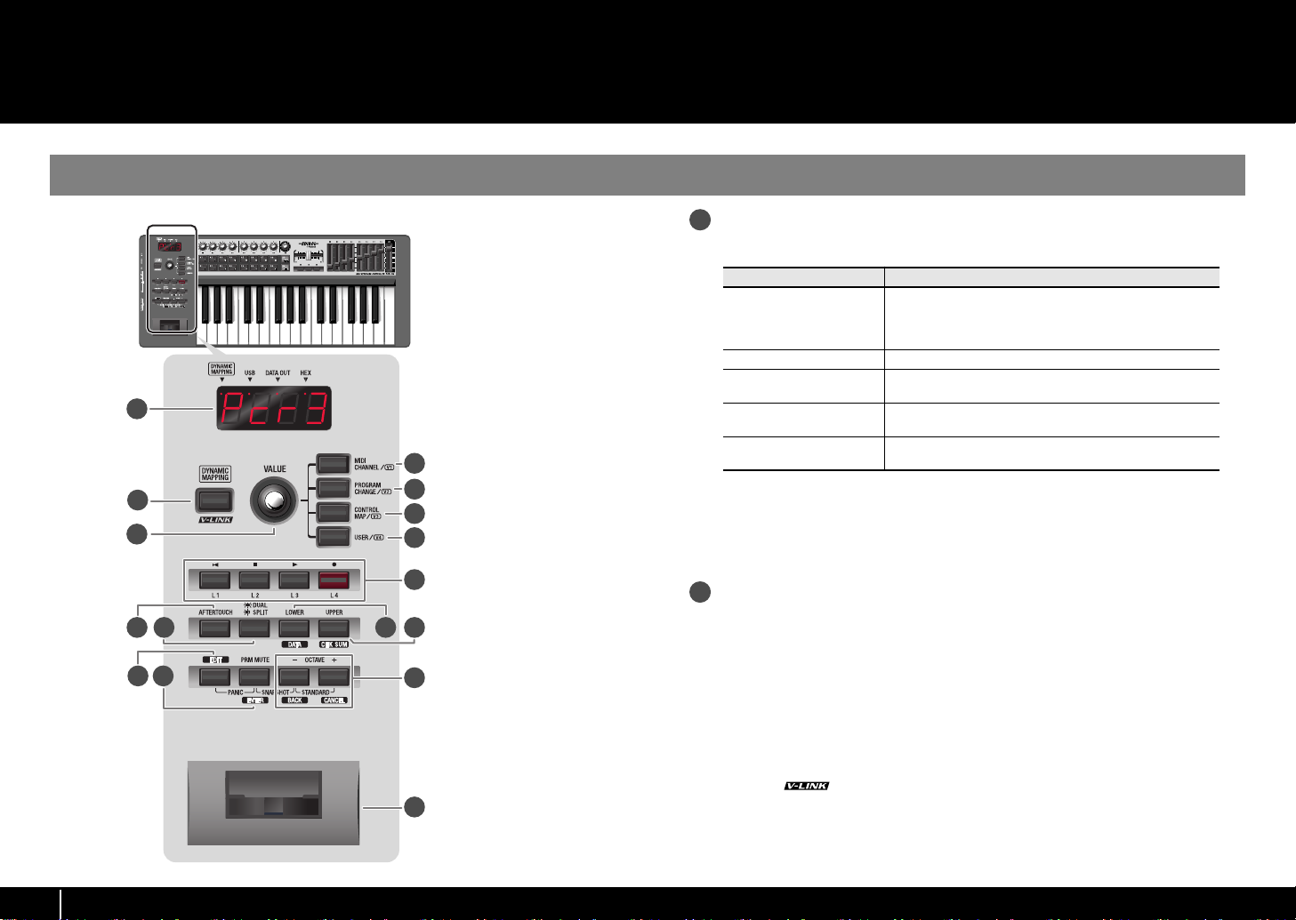
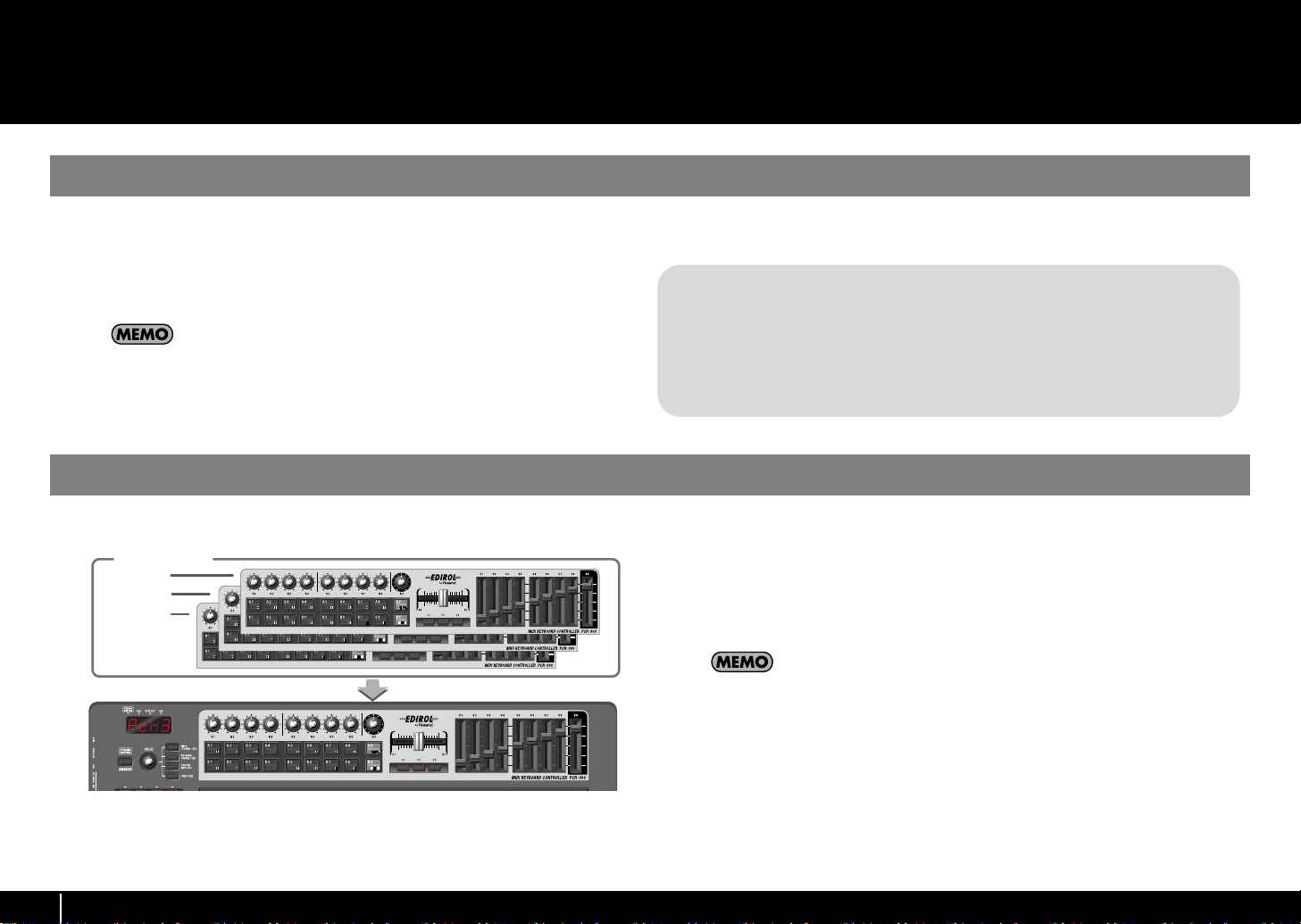
Display
This shows a variety of information, such as the current state.
1
2
3
9
10
13 14
11 12
15
16
Indication
When you operate a controller, the value of the parameter
Alphanumeric characters
DYNAMIC MAPPING This will light when DYNAMIC MAPPING is active.
USB
DATA OUT
4
5
6
7
8
HEX
* The display will dim if you leave the PCR without operating it for several seconds.
* The explanations in this manual include illustrations that depict what should typically be
shown by the display. Note, however, that your unit may incorporate a newer, enhanced
version of the system, so what you actually see in the display may not always match what
appears in the manual.
assigned to that controller is briefly displayed. Information
such as MIDI channels and program changes are also displayed.
This will light when the PCR is connected to your computer
via USB.
This will blink when a MIDI message is transmitted from
USB or MIDI OUT.
This will light when the value shown in the display is a hexadecimal value.
Summary
[DYNAMIC MAPPING] button, [V-LINK] button
When you press the [DYNAMIC MAPPING] button, “DYNAMIC MAPPING” or
“V-LINK” will turn on.
The function of the [DYNAMIC MAPPING] button is specified by the System setting
DYNAMIC MAPPING/V-LINK (p. 81).
DYNAMIC MAPPING
Dynamic Mapping is an extended function for future use. For details, refer to the
Roland website.
V-LINK
V-LINK ( ) is a function that allows music and images to be performed
together. By using MIDI to connect two or more V-LINK compatible devices, you
can easily enjoy a wide range of visual effects that are linked to the expressive
elements of a music performance.
4
Page 5

3
11
121314
15
16
VALUE knob
By turning the VALUE knob you can change the value of the MIDI CHANNEL,
PROGRAM CHANGE, CONTROL MAP, or USER.
In Edit mode, use this knob to select the item that you want to edit.
4
[MIDI CHANNEL] button
After pressing the [MIDI CHANNEL] button so it’s lit, you can turn the VALUE knob
to specify the channel on which the keyboard and bender will transmit messages.
(->
Selecting the current channel (MIDI transmit channel)
5
[PROGRAM CHANGE] button
After pressing the [PROGRAM CHANGE] button so it’s lit, you can turn the VALUE
knob to transmit a program change message on the current channel.
(->
Selecting sounds (Program Change/Bank)
6
[CONTROL MAP] button
After pressing the [CONTROL MAP] button so it’s lit, you can turn the VALUE knob
to switch among control maps stored in the PCR.
(->
Switching control maps
(p. 9))
(p. 34))
(p. 33))
Names of things and what they do
[LOWER] button, [DATA] button
Use this button when you want to play or make settings for the Lower part.
If the [LOWER] button is lit, the keyboard (notes and aftertouch), bender lever
(pitch bend, modulation), foot pedal messages, and program change messages
will be transmitted on the current channel specified for the Lower part.
(->
Selecting the Lower and Upper sounds
(p. 36))
[UPPER] button, [CHK SUM] button
Use this button when you want to play or make settings for the Upper part.
If the [UPPER] button is lit, the keyboard (notes and aftertouch), bender lever (pitch
bend, modulation), foot pedal messages, and program change messages will be
transmitted on the current channel specified for the Upper part.
(->
Selecting the Lower and Upper sounds
(p. 36))
[EDIT] button
Use this button to assign MIDI messages to the controllers or to make system
settings.
(->
Assigning MIDI messages on the PCR keyboard
(->
System settings
(p. 68))
(p. 41))
7
[USER] button
After pressing the [USER] button so it’s lit, you can turn the VALUE knob to change
the value of a user-assigned parameter.
(->
VALUE knob settings
8
Controllers [L1]–[L4] (buttons)
You can assign the desired MIDI messages to these buttons.
(->
Assigning a MIDI message
9
[AFTERTOUCH] button
This specifies whether the keyboard will (ON) or will not (OFF) transmit aftertouch
messages.
10
[DUAL/SPLIT] button
This switches between Dual mode and Split mode.
(->
Layering two sounds (Dual)
(->
Playing two sounds in combination (Split)
(p. 80))
(p. 20))
(p. 37))
(p. 37))
[PRM MUTE] button, [ENTER] button
Use this to mute controller message output.
When you’re not in Play mode, you can use this as the [ENTER] button.
OCTAVE [-]/[+] buttons, [BACK] button, [CANCEL]
button
Use these buttons to raise or lower the octave of the keyboard.
When you’re not in Play mode, you can use these as the [BACK] button, which
returns you to the previous setting, and the [CANCEL] button, which cancels the
setting.
Bender lever, [BEND] and [MOD] controller
You can use this to modify the pitch or to apply vibrato.
You can also assign the desired MIDI messages to this controller.
(->
Assigning MIDI messages on the PCR keyboard
(p. 41))
5
Page 6
Names of things and what they do
20
212223
fig.Panel-Top.eps
17
18
17
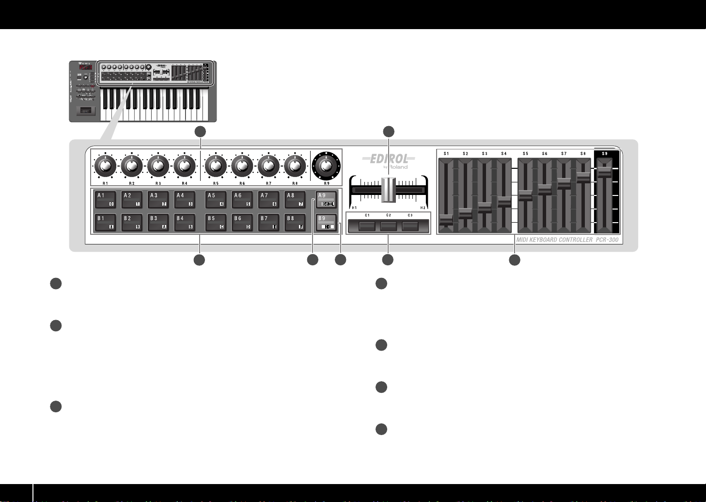
Controllers [R1]–[R9] (knobs)
You can assign the desired MIDI messages to these knobs.
(->
Assigning a MIDI message
18
Controllers [A1]–[A9], [B1]–[B9] (pads)
You can assign the desired MIDI messages to these pads.
(->
Assigning a MIDI message
The force with which you press these controllers can be used to transmit a
corresponding velocity value or aftertouch value.
When you’re not in Play mode, you can use these buttons as [0]–[9] and [A]–[F]
buttons to enter numeric values.
19
[DECIMAL] button
When you’re not in Play mode, you can press this button to switch to decimal input
mode (p. 64).
When you’re in Play mode, this button will function as a conventional controller
[A9].
(p. 20))
(p. 20))
19 20
21
22
23
[HEX] button
When you’re not in Play mode, you can press this button to switch to hexadecimal
input mode (p. 64).
When you’re in Play mode (p. 32), this button will function as a conventional
controller [B9].
Controllers [H1], [H2] (crossfader)
You can assign the desired MIDI messages to this crossfader.
(->
Assigning a MIDI message
(p. 20))
Controllers [C1]–[C3] (buttons)
You can assign the desired MIDI messages to these buttons.
(->
Assigning a MIDI message
(p. 20))
Controllers [S1]–[S9] (sliders)
You can assign the desired MIDI messages to these sliders.
(->
Assigning a MIDI message
(p. 20))
6
Page 7
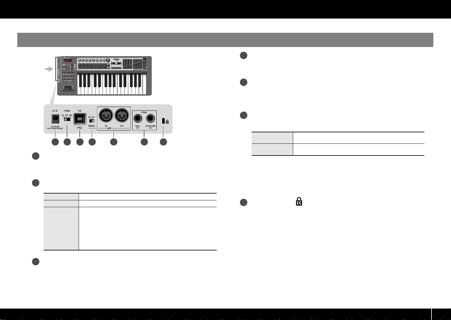
Side panel
27
282930
fig.Panel-Side.eps
Names of things and what they do
MIDI MERGE switch
This switches the MIDI IN message Merge function on/off.
(->
MIDI Merge Destination
(p. 77))
MIDI IN/OUT connectors
You can connect these to the MIDI connectors of other MIDI devices in order to
transmit and receive MIDI messages.
(->
MIDI settings
(p. 76))
Controllers [P1], [P2] (foot pedals)
You can connect suitable pedals to these jacks and use them as controllers.
24 25 26 27 28 29 30
24
DC IN jack
You can connect a separately available AC adaptor (p. 92) to this jack. If you
wish to purchase an AC adaptor, please contact your dealer.
25
Power switch
DC
OFF
USB
26
USB connector
Use this if you’re connecting the PCR to your computer via a USB cable.
Power turned on when using the AC adaptor
Power switched off
Power turned on when a USB cable is connected
You can use the USB (i.e., bus power) setting if the PCR-300/500/
800 is connected to your computer via a USB cable. The power will
be supplied from the computer via the USB cable.
If you want to use the PCR on bus power, set the power switch to the
USB position.
* With some computers, the PCR may not operate on bus power. If
so, you’ll need to use the separately available AC adaptor (p. 92).
HOLD
EXPRESSION
You can assign the desired MIDI messages to these controllers.
(->
Assigning a MIDI message
* Use only the specified expression pedal. By connecting any other expression pedals, you
risk causing malfunction and/or damage to the unit.
You can connect a separately available pedal switch (DP-2, BOSS
FS-5U) here and use it as a hold pedal.
You can connect a separately available expression pedal (EV-5,
EV-7) here and use it to control the tone or volume in real time.
(p. 20))
Security slot ( )
http://www.kensington.com
7
Page 8
Using control maps
Current Memory
What is a control map?
The PCR-300/500/800 have fifty fully assignable controllers; you can freely assign
any MIDI message to each of these controllers.
The MIDI settings assigned to the controllers are collectively called a “control map.”
This is the same as what was called a “memory set” on previous models of the PCR
series.
For details on how to assign MIDI messages to controllers, refer to
Editor
(p. 14) or
MIDI settings that are assigned to the controllers (i.e., the control map) can be stored
in the PCR’s own memory or in DAW software on your computer. Simply by switching
control maps, you can control a wide range of applications.
Assigning MIDI messages on the PCR keyboard
Using PCR
(p. 41).
Control maps and the current memory
About the PCR’s memory
fig.CurrentMemory-e.eps
Control maps
SONAR
Logic
Cubase
:
:
etc...
You can also download the latest control maps from the Roland website and load them
into the PCR.
Memory Sets and Control Maps
The “memory sets” in earlier models of the PCR series are now called “control maps”
on the PCR-300/500/800.
Using the PCR Editor version 2 software included with this product, you can import
“memory sets” and use them as “control maps.”
For details, refer to Using PCR Editor (p. 14).
The PCR-300/500/800 holds sixteen control maps in its internal memory. In order to
use a control map, you must copy it into a location called
Any changes you make to the contents of
turn off the power. If you want to keep the changes you’ve made to
memory
, refer to
Saving a control map
You can use the
loaded into
Startup Memory
current memory
the current memory
(p. 9).
(p. 79) to specify which control map should be
when the power is turned on.
“the current memory.”
will be lost when you
the current
8
Current Memory
Page 9
Using control maps
Switching control maps
When the PCR-300/500/800 is shipped from the factory, it contains sixteen control
maps. By switching among these control maps, you can quickly select control maps
that are suitable for a wide variety of software. For details on the memory numbers of
these control maps and their factory settings, refer to
fig.H-MemorySet.eps
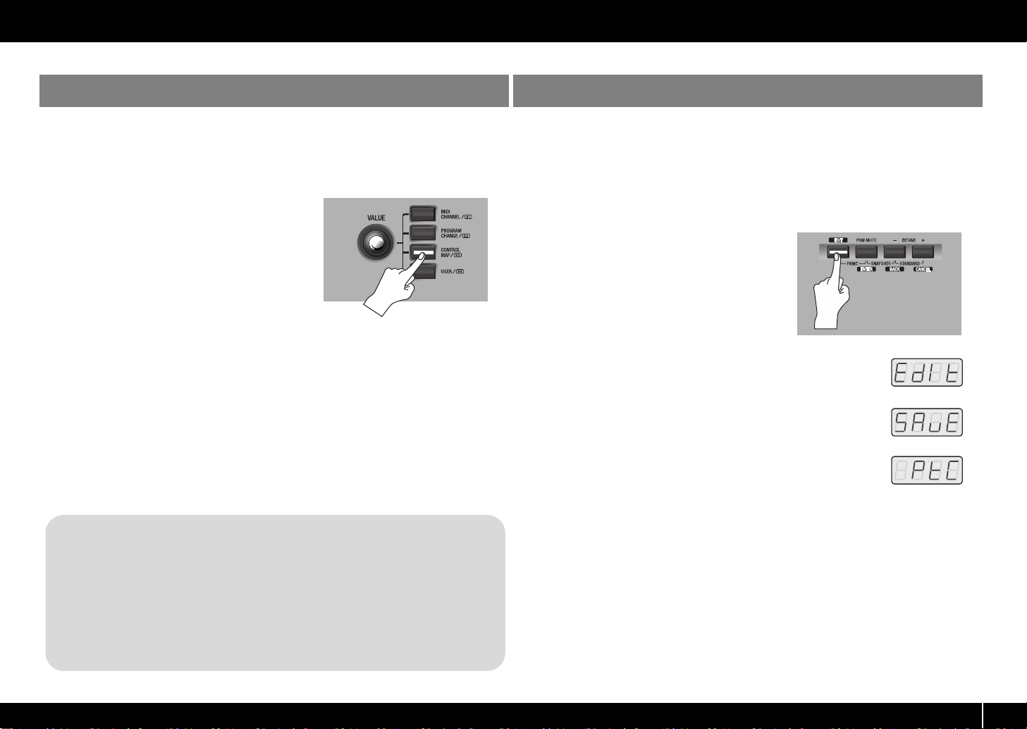
Press the [CONTROL MAP] button.
1
The [CONTROL MAP] button will light.
The display will indicate the currently selected
memory number.
Turn the [VALUE] dial to select the memory
2
number you want to call up.
You can also switch control maps using the following method.
1. Press the [EDIT] button so it’s lit. The display will indicate “EDIT.”
2. Press the [CONTROL MAP] button. It will light, and the display will
indicate the currently selected memory number.
3. Use controllers [A1]–[A8], [B1]–[B8], or the VALUE knob to specify the
memory number you want to call up.
4. Press the [ENTER] button.
Control map list
(p. 90).
Saving a control map
If you want to keep the changes you’ve made to the current memory, use the following
procedure to save the control map.
You can save the control map in memory numbers 1–F. You can’t save to memory
number 0.
* If you’ve changed the settings of the current memory, be sure to “SAVE” if you want to keep
your changes.
fig.H-Edit.eps
Press the [EDIT] button so it’s lit.
1
fig.D-Edit.eps
The display will indicate “EDIT.”
fig.D-Save.eps
2
Turn the VALUE knob to make the display indicate “SAVE.”
fig.D-Protect.eps
3
Press the [ENTER] button.
* If the display indicates “PTC,” the Protect setting is ON, and you’ll be
unable to save the memory. Turn the Protect setting OFF, and repeat the
procedure from step 1.
(->
Protecting the control maps
4
Use the VALUE knob or controllers [A1]–[A8] and [B1]–[B8] to specify the
memory number “1”–”F” in which you want to save the control map. The
specified memory number will blink in the display.
5
Press [ENTER] to save the control map.
* If you press another button instead of the [ENTER] button, the Save operation will be cancelled.
(p. 13))
9
Page 10
Using control maps
Receiving a control map from your computer (Bulk Receive)
The PCR-300/500/800 can receive control map data in the form of a bulk dump.
If you want control map data you’ve created using PCR Editor to be received into the
PCR’s current memory, you’ll need to make settings in PCR Editor so that the PCR will
be ready to receive a bulk dump. If you want the PCR to receive this data as messages
from your DAW software, you’ll need to make settings on the PCR keyboard so that it
will be ready to receive a bulk dump.
Here we’ll explain how to make settings on the PCR keyboard so that it will be able
to receive a bulk dump.
For more about PCR Editor, refer to
to receive a control map from PCR Editor, refer to
Editor and the PCR
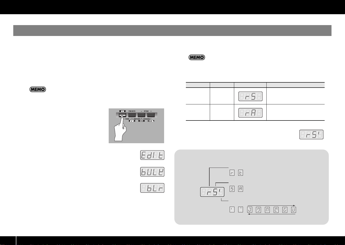
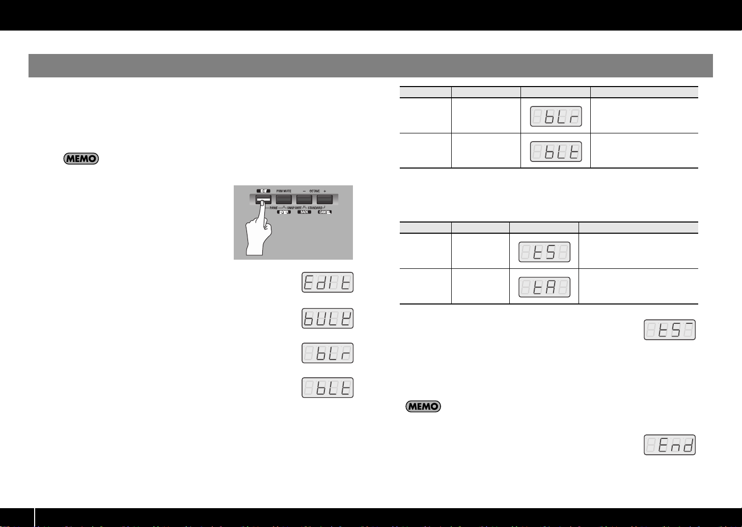
fig.H-Edit.eps
1
Press the [EDIT] button so it’s lit.
fig.D-Edit.eps
(p. 22).
Using PCR Editor
Transferring data between PCR
(p. 14). For details on how
The display will indicate “EDIT.”
fig.D-Bulk.eps
2
Turn the VALUE knob to make the display indicate “BULK.”
fig.D-BulkR.eps
3
Press the [ENTER] button.
“BLR” will blink in the display (Bulk Receive).
4
Verify that the display indicates “BLR” (Bulk Receive), and then press the [ENTER]
button.
If the display indicates “BLT” (Bulk Transmit), use the VALUE knob to make it
indicate “BLR” (Bulk Receive).
5
Use the VALUE knob or the controllers to choose the reception method. Choose
the method that’s appropriate for the data you’ll be receiving.
Controller
[A1 (0)]
[A2 (1)] ALL BULK
fig.D-RSBulk-Wait.eps
6
Verify that the display indicates the correct choice, and press the
Item Display Explanation
SINGLE
BULK
One control map will be received.
The received data will overwrite the
current memory.
Memories 1–F will not be affected.
Data for all fifteen control maps will
be received. The received data will
overwrite internal memories 1–F.
[ENTER] button. The rightmost digit of the display will blink, and
the PCR will wait for bulk data to arrive.
About the display in Bulk mode
Receive/Transmit
TransmitReceive
SINGLE BULK / ALL BULK
ALL
SINGLE
BULK
BULK
Transmitting/Receiving/Waiting
Receiving
10
Receive
Waiting
(blinking)
Transmit
Waiting
(blinking)
Transmitting
Page 11
7
Operate PCR Editor or your DAW software to transmit the control map data.
Select “EDIROL PCR” as the MIDI output device for PCR Editor or your DAW
software. For details on how to make this setting in your DAW software, refer to
the owner’s manual for the DAW software you’re using.
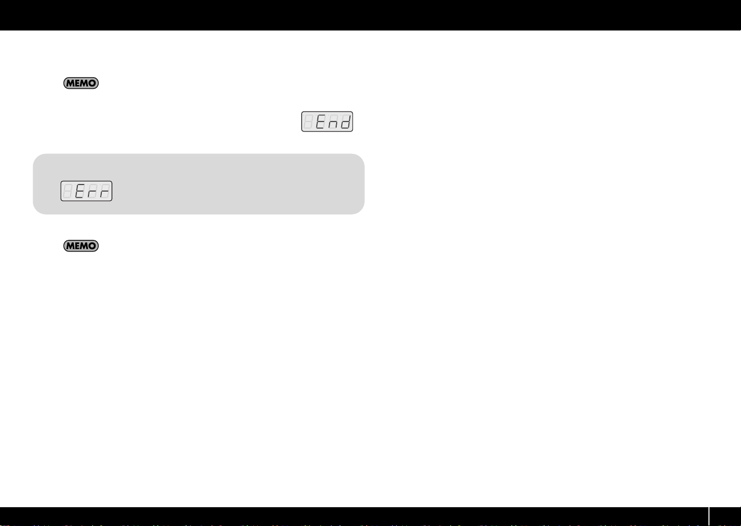
fig.D-End.eps
When the PCR has finished receiving the control map data, the
8
display will indicate “END.” Press the [ENTER] button to complete
the operation.
Error indication
If the data was not received correctly, “ERR” will be blinking in the
display. If this occurs, press the [CANCEL] button and perform the
procedure again from step 1.
Control map data received as Single Bulk will be loaded into the current
memory, meaning that it will be lost when you turn off the power. However, if
you save this control map into one of the internal memories, you won’t need to
re-transmit it to the PCR. Refer to
Saving a control map
(p. 9).
Using control maps
11
Page 12
Using control maps
Saving control map data on your computer (Bulk Transmit)
The PCR-300/500/800 can transmit control map data to your DAW software in the
form of a bulk dump.
In order to transmit a control map you’ve edited on the PCR keyboard to PCR Editor
or other software you’re using, you’ll need to make settings on the PCR to make it
transmit the bulk data.
For more about PCR Editor, refer to
to transmit a control map from PCR Editor, refer to
PCR Editor and the PCR
fig.H-Edit.eps
1
Press the [EDIT] button so it’s lit.
fig.D-Edit.eps
(p. 22).
Using PCR Editor
(p. 14). For details on how
Transferring data between
The display will indicate “EDIT.”
fig.D-Bulk.eps
2
Turn the VALUE knob to make the display indicate “BULK.”
fig.D-BulkR.eps
3
Press the [ENTER] button.
“BLR” will blink in the display (Bulk Receive).
fig.D-BulkT.eps
Turn the VALUE knob to make the display indicate “BLT” (Bulk
4
Transmit).
Alternatively, you can press controller [A2 (1)] instead of using the
VALUE knob.
Controller
[A1 (0)]
[A2 (1)] BULK TRANSMIT Transmit bulk data
Press the [ENTER] button.
5
6
Use the VALUE knob or controllers to choose the type of transmission. Choose the
Item Display Explanation
BULK RECEIVE Receive bulk data
type of data you want to transmit.
Controller
[A1 (0)] SINGLE BULK
[A2 (1)] ALL BULK
fig.D-TSBulk-Wait.eps
7
Check the indication in the display, then press the [ENTER] button.
Item Display Explanation
The control map data of the current
memory will be transmitted.
Data for all fifteen control maps in
internal memory (memories 1–F)
will be transmitted.
The rightmost digit of the display will blink, and the PCR will wait to
transmit bulk data.
8
Put PCR Editor or your DAW software in recording mode, and then press the
PCR’s [ENTER] button. Data transmission will begin.
Choose “EDIROL PCR 2” as the MIDI input port for PCR Editor or your DAW
software. For details on how to make this setting in your DAW software, refer to
the owner’s manual for the software you’re using.
fig.D-End.eps
When the PCR has finished transmitting the control map data, the
9
display will indicate “END.” Press the [ENTER] button to complete
the operation. You’ll also need to stop recording on your DAW
software.
12
Page 13
Protecting the control maps
By turning the Protect setting on, you can protect the control map data from being
accidentally overwritten.
This will disable All Bulk reception (p. 10) and Save (p. 9) operations, protecting your
valuable data from being overwritten.
The Protect on/off setting is remembered even when the PCR is powered off.
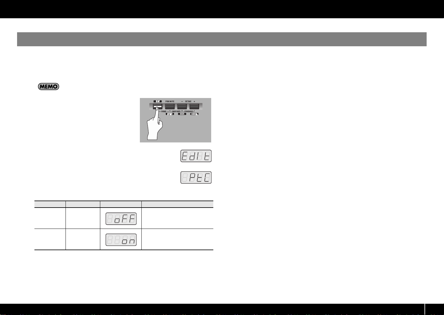
Press the [EDIT] button so it’s lit.
1
fig.D-Edit.eps
The display will indicate “EDIT.”
fig.D-Protect.eps
2
Turn the VALUE knob to make the display indicate “PTC.”
3
Check the indication in the display, then press the [ENTER] button.
The display will indicate the current protect status.
fig.H-Edit.eps
Using control maps
Controller
[A1 (0)] PROTECT OFF
[A2 (1)] PROTECT ON
4
Use the VALUE knob to choose the desired setting, and press the [ENTER] button.
Item Display Explanation
Control map data in internal memory can be rewritten.
Control map data in internal memory cannot be rewritten.
13
Page 14
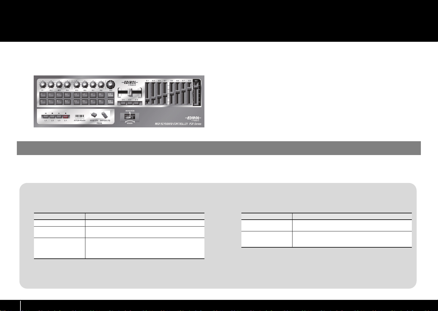
Using PCR Editor
PCR Editor Ver. 2 is an application that lets you use your computer to create control
maps (called “memory sets” on earlier models of the PCR series) for the EDIROL PCR
series.
fig.controller.eps
Setting the MIDI ports
In order to transfer control maps between PCR Editor and the PCR, you’ll need to
specify the MIDI ports that PCR Editor is to use.
What are MIDI ports?
Input ports
Input port Explanation
EDIROL PCR MIDI IN Receives data that arrives at the PCR’s MIDI IN connector.
EDIROL PCR 1
EDIROL PCR 2
The output destination for the MIDI messages sent when you operate the PCR’s
sliders, knobs, and buttons can be specified independently for each controller. For
details, refer to Two MIDI ports (p. 88).
Receives data from the PCR’s sliders, knobs, and buttons that
are assigned to “PORT 1.”
Receives data from the PCR’s sliders, knobs, and buttons that
are assigned to “PORT 2.”
If you’re receiving bulk data from the PCR, choose “PCR 2” as
the input port.
The PCR-300/500/800 has a total of fifty controllers: [R1]–[R9], [S1]–[S9], [A1]–
[A9], [B1]–[B9], [C1]–[C3], [L1]–[L4], [H1]–[H2], [P1]–[P2], [BEND], [MOD], and
[AFTERTOUCH]. You can freely assign the MIDI message that will be transmitted by
each of these controllers.
Although it is possible to make MIDI message assignments on the PCR itself (->
Assigning MIDI messages on the PCR keyboard
since this allows you to easily assign messages in a graphical screen that resembles
the PCR’s panel.
The fifty messages assigned to the controllers are collectively called a “control map.”
PCR Editor Ver. 2 lets you edit control map data and transfer it between the PCR and
your computer, and also save or load control map settings as SMF data.
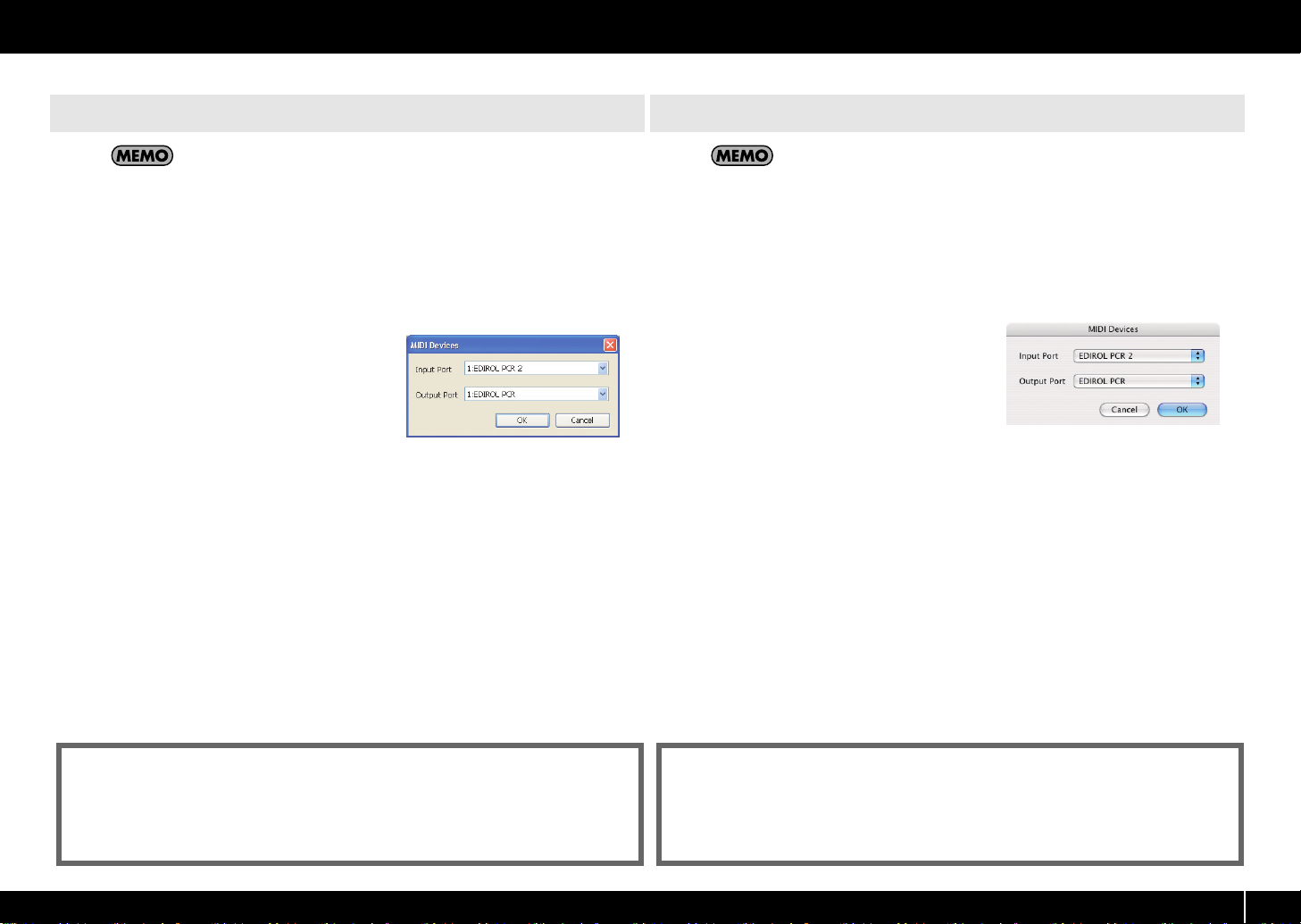
* The explanation that follows is for when the PCR is connected via USB. If you’re using a MIDI
connection, specify the MIDI input port and MIDI output to which your PCR is MIDI-connected
instead of “EDIROL PCR 2” and “EDIROL PCR.”
(p. 41)), it’s easiest to use PCR Editor,
Output ports
Output port Explanation
EDIROL PCR MIDI OUT
EDIROL PCR
In order to send a control map you’ve created in PCR Editor to the PCR so that it
can be used, you’ll need to select “PCR” as the output port.
Transmits MIDI messages to the device connected to the PCR’s
MIDI OUT connector.
Transmits MIDI messages to the PCR.
If you’re sending bulk data to the PCR, choose “PCR” as the
output port.
14
Page 15
Using PCR Editor
Windows users
If you have not yet installed PCR Editor in your computer, install it now as
described in the included setup guide.
1
Use a USB cable to connect the PCR to your computer, then switch on the PCR’s
power.
In Windows, choose [Start]-[All Programs]-[PCR Editor V2]-[PCR Editor 2] to start
2
up PCR Editor.
3
In PCR Editor, choose [Options]-[MIDI Devices].
fig.WinMIDIPort-e.eps
4
In the MIDI Devices dialog box, make the MIDI
device settings shown in the illustration.
5
Click [OK] to close the dialog box.
Mac OS X users
If you have not yet installed PCR Editor in your computer, install it now as
described in the included setup guide.
1
Use a USB cable to connect the PCR to your Mac, then switch on the PCR’s
power.
2
From the Mac Finder, open the [Applications]-[PCR Editor V2] folder, and
double-click PCR Editor V2 to start up PCR Editor.
In PCR Editor, choose [Options]-[MIDI Devices].
3
fig.MacMIDIPort-e.eps
In the MIDI Devices dialog box, make the MIDI
4
device settings shown in the illustration.
5
Click [OK] to close the dialog box.
* Microsoft and Windows are registered trademarks of Microsoft Corporation.
* The screen shots in this document are used in compliance with the guidelines of the Microsoft
Corporation.
* Windows
®
is known officially as: “Microsoft® Windows® operating system.”
* Apple and Macintosh are registered trademarks of Apple Computer, Inc.
* Mac OS is a trademark of Apple Computer, Inc.
15
Page 16
Using PCR Editor
Explanation of the menus
File menu
Menu
New
Open
Save
Save As
Import Memory Set
Export Assign List
View Assign List
Creates a new control map.
In the new control map, all controllers will be set to “NO ASSIGN.”
Loads a control map that was saved in SMF format.
For details, refer to
Saves the control map currently being edited by overwriting the
original SMF.
Saves the control map currently being edited in SMF format with
the name you specify. For details, refer to
on your computer
Loads a memory set created in PCR Editor version 1 as a version
2 control map.
Exports an HTML-format list of the messages assigned to each controller of the control map currently being edited.
* The HTML file created by this command cannot be loaded by
means of [File]-[Open].
Displays an HTML-format list of the messages assigned to each
controller of the control map currently being edited.
Explanation
Loading a control map
(p. 23).
Edit menu
Menu
Copy
Paste Pastes the setting from the clipboard to the selected controller.
NO ASSIGN Sets the assignment of the selected controller to “NO ASSIGN.”
Copies the setting of the selected controller to the clipboard.
Explanation
(p. 23).
Saving a control map
Communication menu
Menu
Transmits the control map currently being edited to the current
Transmit
Receive
memory of the PCR keyboard.
For details, refer to
PCR
(p. 22).
Receives the current memory of the PCR into PCR Editor.
For details, refer to
PCR
(p. 22).
Options menu
Menu
MIDI Devices
Show Messages
Specifies the MIDI ports used to communicate with the PCR keyboard.
For details, refer to
Shows the MIDI message settings assigned to each controller in
the main window of PCR Editor. For details, refer to
assigned MIDI messages
Help menu
Menu Explanation
PCR Editor Help
Opens the online manual.
Explanation
Transferring data between PCR Editor and the
Transferring data between PCR Editor and the
Explanation
Setting the MIDI ports
(p. 21).
(p. 14).
Viewing the
16
Page 17
Keyboard shortcuts
You can use the following keyboard shortcuts in PCR Editor.
Using PCR Editor
Command
[File]–[New] Ctrl + N Command + N
[File]–[Open] Ctrl + O Command + O
[File]–[Save] Ctrl + S Command + S
[File]–[Save As] Ctrl + Shift + S Command + Shift + S
[File]–[Exit] Alt + F4 Command + Q
[Edit]–[Copy] Ctrl + C Command + C
[Edit]–[Paste] Ctrl + V Command + V
[Edit]–[NO ASSIGN] Del Del
Next controller Ctrl + F Command + F
Previous controller Ctrl + B Command + B
* In some text boxes, such as the main window’s Title field, the [Edit]–[Copy] and [Edit]–[Paste]
commands are used for text editing.
Windows Macintosh
17
Page 18
Using PCR Editor
123
Explanation of each window
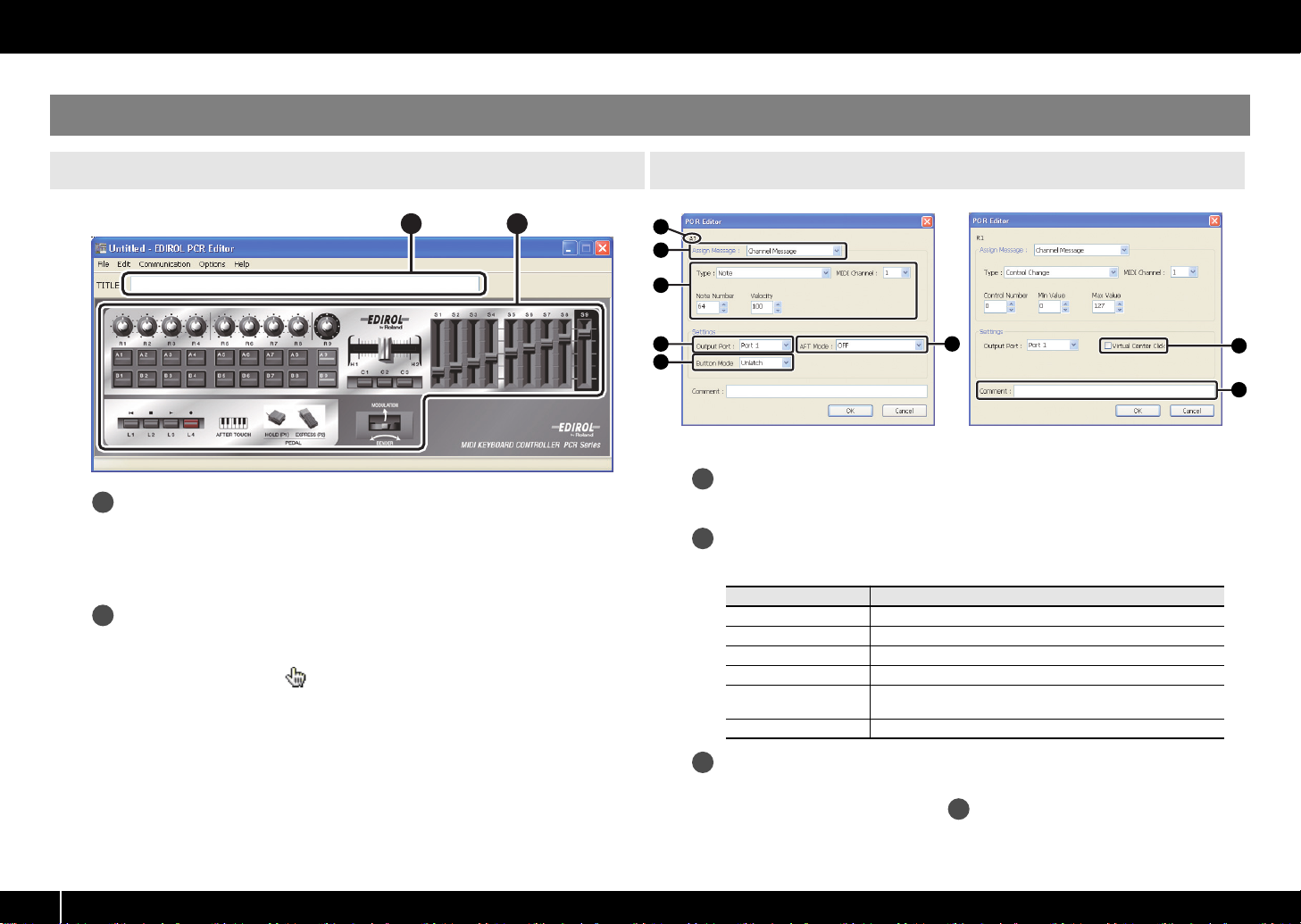
Main window
fig.EditorMainWindow-e.eps
1
Title
You can enter a name for the control map currently being edited. Only single-byte
alphanumeric characters can be entered as the control map name.
The name you enter here is displayed as the title of the HTML file produced by the
[File]-[Export Assign List] command.
2
Controllers
Click the controller to which you want to assign a MIDI message. When you move
the mouse over a controller (i.e., over the clickable area of a controller), the mouse
cursor will change to the shape. A message assignment window will open
when you click the controller in this state.
Message assignment window
fig.EditorMessageWindow1.epsfig.EditorMessageWindow2.eps
1
2
1
2
3
4
5
* The available items will depend on the controller and on the type of message you assign.
6
7
8
Controller name
Shows the name of the controller you’re editing.
Assign Message
Lets you select the type of MIDI message to assign to the controller.
Menu Explanation
NO ASSIGN
Channel Message Assigns a channel message (CC, note, etc.)
System Realtime/F6 Assigns a system realtime message or F6 (Tune Request)
System Ex Assigns a system exclusive message of up to twenty-four bytes
Free Message
Tempo Assigns tempo control
Cancels the MIDI message assignment
Assigns a MIDI message of up to twenty-four bytes
(multiple messages are allowed)
18
Message assignment fields
Here you can specify the value for each parameter of the MIDI message you’ve
selected in the Assign Message list .
For details on the parameters of each MIDI message, refer to
items
(p. 24).
2
Parameter setting
Page 19
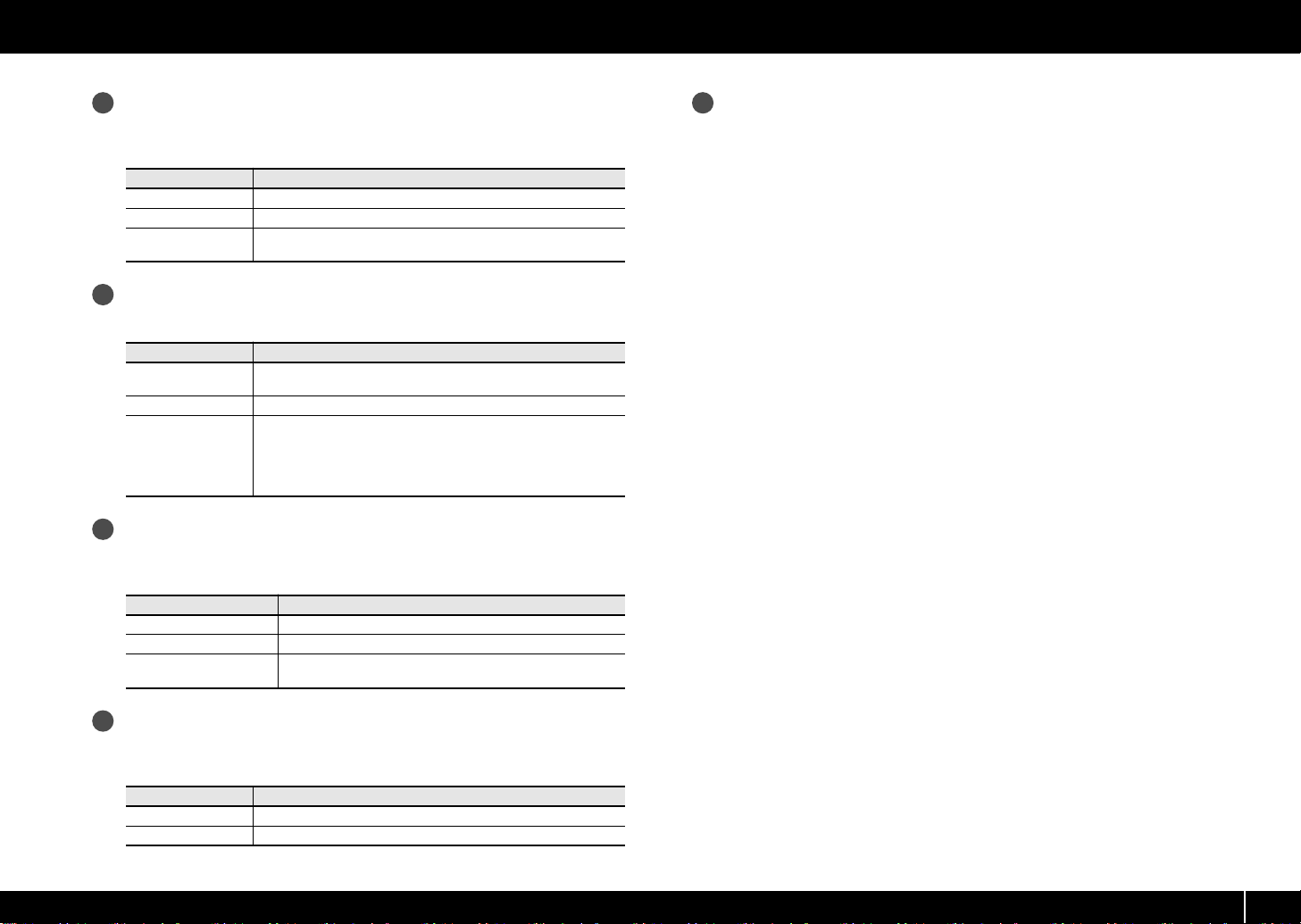
4
8
Output Port
This specifies the USB port on the USB-connected computer to which the MIDI
message will be sent.
Port
Port 1
Port 2 The message will be sent to “EDIROL PCR 2.”
Port 1+2
5
Button Mode
The message will be sent to “EDIROL PCR 1.”
The message will be sent to both “EDIROL PCR 1” and “EDIROL
PCR 2.”
Explanation
For a button-type controller, this specifies the button’s mode.
Using PCR Editor
Comment
You can enter a comment for the assigned message. Only single-byte
alphanumeric characters can be used when entering the comment.
The comment you enter here is shown in the “PARAMETER” column of the HTML
file produced by the [File]-[Export Assign List] command.
* Comments can be loaded only from an SMF file saved by PCR Editor.
Mode
Unlatch
Latch Button acts as a toggle, switching on or off each time it’s pressed.
Increase
6
Aftertouch Mode
Switched on when button is pressed; switched off when button is
released.
Each time you press the button, the value will increment by 1 (or
decrement by 1 if the minimum value is higher than the maximum
value). When the value has reached the maximum (minimum) value, it will “wrap around” to the minimum (maximum) value.
* You can’t select this if the message type is NOTE.
Explanation
If the controller currently being edited is [A1]–[A9] or [B1]–[B9], this specifies the
aftertouch setting.
Mode
OFF No aftertouch.
Channel Pressure Channel aftertouch will be applied to the specified channel.
Polyphonic Key Pressure
7
Virtual Center Click
Polyphonic aftertouch will be applied to an individual note
number.
Explanation
If the controller currently being edited is [R1]–[R9] or [S1]–[S9], this specifies a
virtual center click (p. 65).
Mode
OFF
ON “Dead zone” near the center.
No “dead zone” near the center.
Explanation
19
Page 20
Using PCR Editor
Using PCR Editor to assign MIDI messages
Assigning a MIDI message
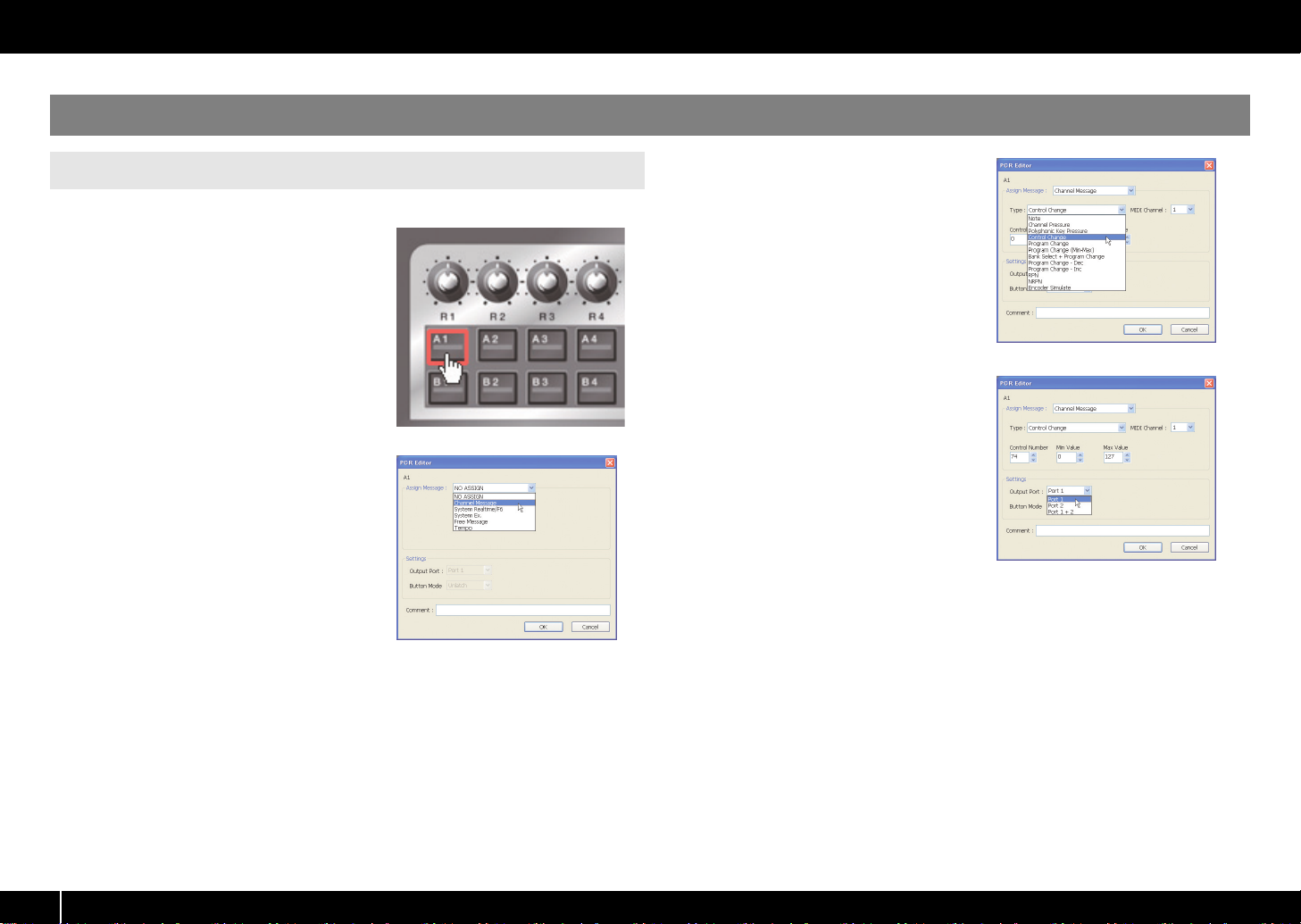
Here’s how to assign a MIDI message to each controller.
fig.EH-Assign.eps_81
In the main window, click the controller to
1
which you want to assign a MIDI message.
fig.EH-AssignMessage.eps_25
2
In the message assignment window, use the
Assign Message field to select the type of
MIDI message that you want to assign.
fig.EH-AssignType.eps_25
3
According to the type of MIDI message
you’ve selected, set the various parameters in
the message assignment area.
For details on the parameters, refer to
Parameter setting items
fig.EH-AssignPort.eps_25
4
In the Output Port field, specify the MIDI
output port.
5
If desired, use the Comment field to add a
comment.
Click [OK].
6
(p. 24).
20
Page 21
Using PCR Editor
Viewing the assigned MIDI messages
You can use either of the following two methods to view the MIDI messages you’ve
assigned.
Assignment list
If you want to use your browser to view a list of the assignments for the current control
map, choose [File]-[View Assign List]. This method is convenient when you want to see
the control map settings at a glance. If you want to save the assignment list as an HTML
file, choose [File]-[Export Assign List]. The “Save As” dialog box will appear; specify
the save destination, assign a file name, and click [Save].
Viewing the assigned messages
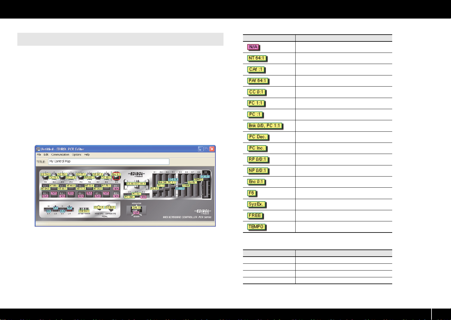
If you want the current settings to be shown on each controller in the main window,
choose [Options]-[Show Messages], and add a check mark next to [Show Messages].
This method shows the current settings in simplified form as follows.
fig.EditorViewAssign-e.eps
Display
Meaning
NO ASSIGN
Note
Channel Pressure
Polyphonic Key Pressure
Control Change
Program Change
Program Change (Min-Max)
Bank Select + Program Change
Program Change - Dec
Program Change - Inc
RPN
NRPN
Encoder Simulate
System Realtime/F6
System Ex.
Free Message
Tempo
The color of the indication shows the Output Port setting.
Color Output Port
Yellow
Light blue Port 2
Light green Ports 1+2
Pink NO ASSIGN
Port 1
21
Page 22
Using PCR Editor
Transferring data between PCR Editor and the PCR
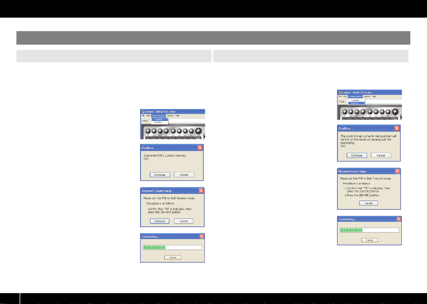
Sending
If you’ve used PCR Editor to create control map settings and want to use them on the
PCR keyboard, you’ll need to send the control map currently being edited to the PCR’s
current memory as described below.
* When you send this data, the PCR’s current memory will be overwritten. If you want to preserve
the settings of the PCR’s current memory, you must save them as one of the internal control maps.
(->
Saving a control map
fig.EditorT1-e.eps
From the menu bar, choose [Communication]-
1
[Transmit].
fig.EditorT2-e.eps
A confirmation dialog box will appear. Click
2
[Continue].
fig.EditorT3-e.eps
The Transmit Control Map dialog box will appear.
3
As instructed by the dialog box, set the PCR to wait
for bulk data to be received.
When you’re ready, click [Continue].
4
fig.EditorR4-e.eps
5
A dialog box will indicate that the data is being
transferred.
When the dialog box disappears, transmission has
been completed.
(p. 9))
Receiving
If you want to use PCR Editor to edit a control map that’s currently in the PCR
keyboard, you’ll need to load the control map from the PCR’s current memory into PCR
Editor so that it can be edited. Proceed as follows:
fig.EditorR1-e.eps
From the menu bar, choose [Communication]-
1
[Receive].
fig.EditorR2-e.eps
A confirmation dialog box will appear. Click
2
[Continue].
fig.EditorR3-e.eps
The Receive Control Map dialog box will appear.
3
As instructed by the dialog box, transmit bulk data
from the PCR.
fig.EditorR4-e.eps
4
A dialog box will indicate that the data is being
transferred.
When the dialog box disappears, reception has
been completed.
5
The PCR’s display will indicate “END.” Press the
PCR’s [ENTER] button to return to Play mode.
22
6
The PCR’s display will indicate “END.” Press the
PCR’s [ENTER] button to return to Play mode.
Page 23

Using PCR Editor
Saving a control map on your computer
A control map that you edit using PCR Editor can be saved as an SMF-format file on
your computer, as well as being transferred to or from the PCR keyboard.
* The comments that have been entered for the controllers are also saved in the SMF.
To save a control map as an SMF file, proceed as follows.
1
From the menu bar, choose [File]-[Save As].
If you want to save the settings while overwriting the file that was most recently
opened, choose [File]-[Save].
Specify a file name and click [Save].
2
Loading a control map
You can load control map data that was saved in SMF format.
* You can’t load an SMF that does not include PCR control map data. The SMF must contain
settings for all controllers.
* The contents of the comment field can be loaded only from an SMF file that was saved by PCR
Editor.
Here’s how to load a control map from an SMF file.
1
From the menu bar, choose [File]-[Open].
Specify the SMF file that you want to load, and click [Open].
2
Loading a memory set as a control map
A “memory set (SMF file)” created for an earlier model in the PCR series can be loaded
as a “control map” for the PCR-300/500/800.
Importing a memory set
Controllers that do not exist on earlier models of the PCR series will be set to “NO
ASSIGN.”
* You can’t load an SMF that does not contain memory set data for an earlier model of the PCR
series. The SMF must contain settings for all controllers of the earlier PCR series model.
Here’s how to import a memory set.
From the menu bar, choose [File]-[Import Memory Set].
1
Specify the file that you want to load, and click [Open].
2
23
Page 24
Using PCR Editor
Parameter setting items
The setting items shown in the message assign window will depend on the MIDI message you’ve selected. This section explains the setting items for each MIDI message. Values for
parameters are specified in decimal.
* Within the explanation, values in square brackets [ ] are in hexadecimal.
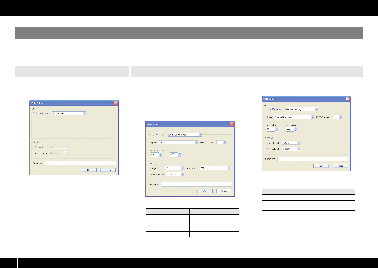
NO ASSIGN
Clears any message assignment.
No message will be sent even if you operate a
controller that’s set to NO ASSIGN.
fig.EditorNoAssign.eps_35
NO ASSIGN has no parameters to set.
Channel Message
Assigns a channel message.
Use the Type field to select the type of message you
want to assign. According to the message you’ve
selected, set the following parameters.
Note [9n kk vv]
Assign a note message.
fig.EditorChannelMessage.eps_35
You can specify the following parameters for Note.
Item
MIDI Channel
Note Number Note number [kk]
Velocity Velocity [vv]
AFT Mode Aftertouch
Content
MIDI channel [n]
Channel Pressure [Dn vv]
Assign a channel pressure message.
fig.EditorChPres.eps_35
You can specify the following parameters for
Channel Pressure.
Item
MIDI Channel MIDI channel [n]
Min Value
Max Value
Content
Lower value [vv] of channel
pressure
Upper value [vv] of channel
pressure
24
Page 25
Channel Message
Using PCR Editor
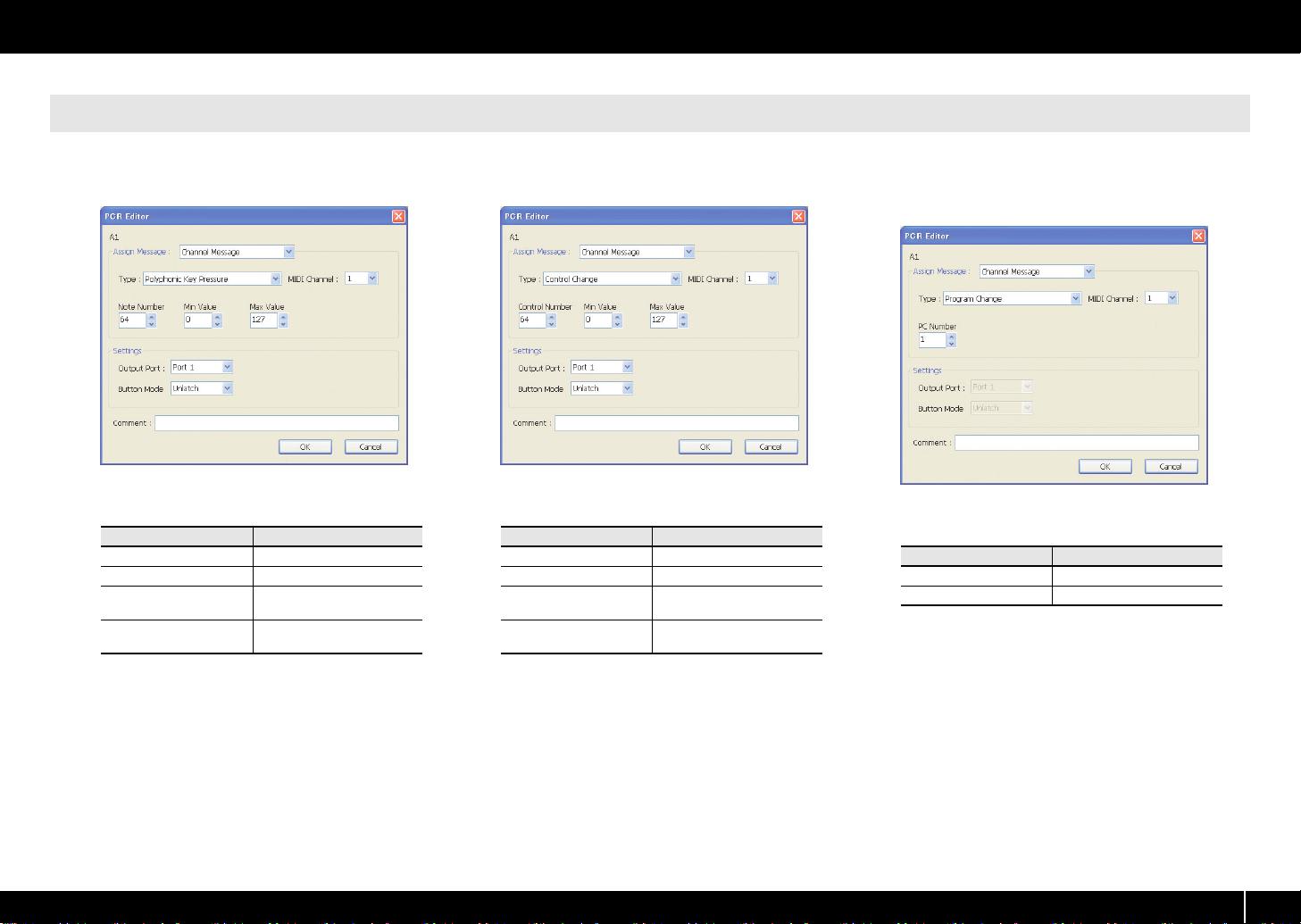
Polyphonic Key Pressure [An kk vv]
Assign a polyphonic key pressure message.
fig.EditorPolyKeyPres.eps_35
You can specify the following parameters for
Polyphonic Key Pressure.
Item
MIDI Channel MIDI channel [n]
Note Number Note number [kk]
Min Value
Max Value
Content
Lower value [vv] of key
pressure
Upper value [vv] of key
pressure
Control Change [Bn cc vv]
Assign a control change message.
fig.EditorCC.eps_35
You can specify the following parameters for Control
Change.
Item
MIDI Channel MIDI channel [n]
Control Number Control number [cc]
Min Value
Max Value
Content
Lower limit of the control
value [vv]
Upper limit of the control
value [vv]
Program Change [Cn pp]
Assign a program change message (with a fixed
program number).
fig.EditorPC1.eps_35
You can specify the following parameters for
Program Change.
Item Content
MIDI Channel
PC Number Program number [pp]
* The range of the program number [pp] is 1–128.
MIDI channel [n]
25
Page 26
Using PCR Editor
Channel Message
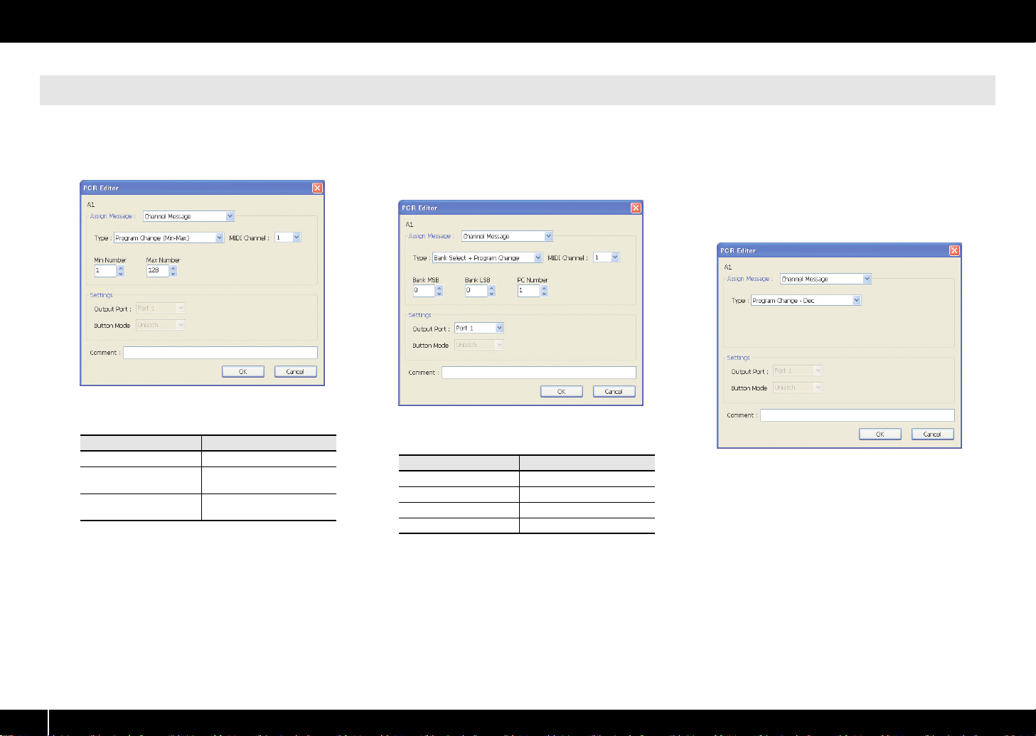
Program Change (Min-Max) [Cn pp]
Assign a program change message (with a variable
program number).
fig.EditorPC2.eps_35
You can specify the following parameters for
Program Change (Min-Max).
Item Content
MIDI Channel
Min Number
Max Number
* The range of the program number [pp] is 1–128.
MIDI channel [n]
Lower limit of the program
number [pp].
Upper limit of the program
number [pp].
Bank Select + Program Change
[Bn 00 mm Bn 20 ll Cn pp]
Assign a bank select message and program change
message (all values fixed).
fig.EditorBankSelect.eps_35
You can specify the following parameters for Bank
Select + Program Change.
Item Content
MIDI Channel
Bank MSB Bank number MSB [mm]
Bank LSB Bank number LSB [ll]
PC Number Program number [pp]
* The range of the program number [pp] is 1–128.
MIDI channel [n]
Program Change – Dec
Assign the program change decrement function (PC
DEC).
This will transmit a program change number that is
one less than the program change number most
recently transmitted in the PCR’s program change
mode.
fig.EditorPCDec.eps_35
There are no parameters to specify for Program
Change – Dec.
26
Page 27
Channel Message
Using PCR Editor
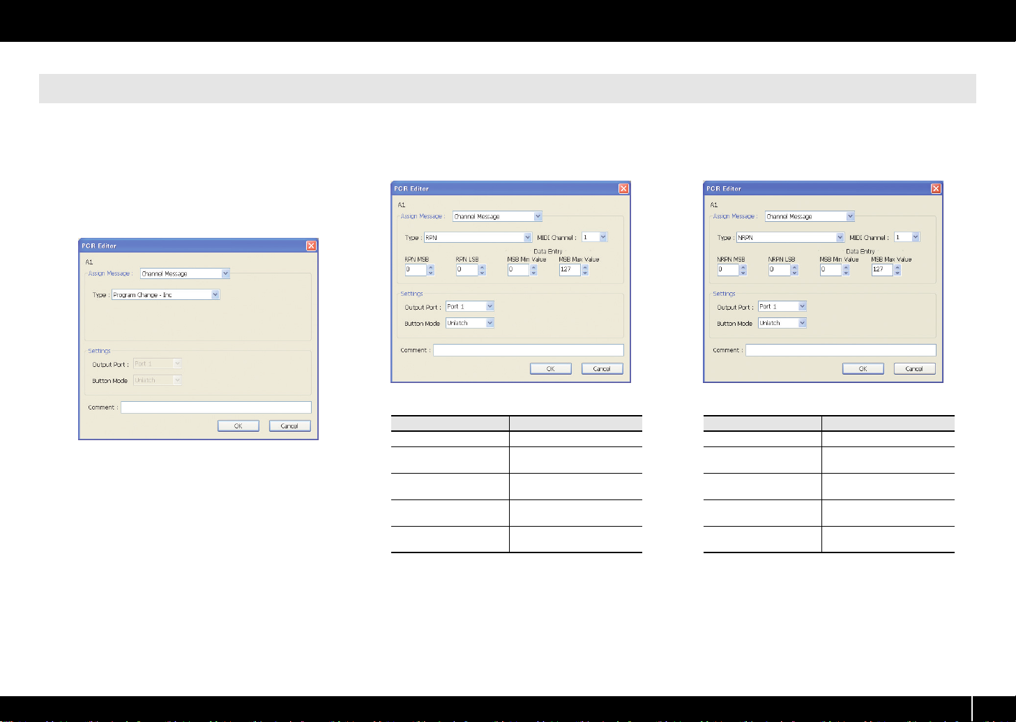
Program Change – Inc
Assign the program change increment function (PC
INC).
This will transmit a program change number that is
one greater than the program change number most
recently transmitted in the PCR’s program change
mode.
fig.EditorPCInc.eps_35
There are no parameters to specify for Program
Change – Inc.
RPN
[Bn 65 mm Bn 64 ll Bn 06 dm Bn 26 dl]
Assign a registered parameter number.
fig.EditorRPN.eps_35
You can specify the following parameters for RPN.
Item
MIDI Channel
RPN MSB
RPN LSB
MSB Min Value
MSB Max Value
Content
MIDI channel [n]
RPN parameter number
MSB [mm]
RPN parameter number LSB
[ll]
Lower limit of data entry
MSB [dm]
Upper limit of data entry
MSB [dm]
NRPN
[Bn 63 mm Bn 62 ll Bn 06 dm Bn 26 dl]
Assign a non-registered parameter number.
fig.EditorNRPN.eps_35
You can specify the following parameters for NRPN.
Item
MIDI Channel
NRPN MSB
NRPN LSB
MSB Min Value
MSB Max Value
Content
MIDI channel [n]
NRPN parameter number
MSB [mm]
NRPN parameter number
LSB [ll]
Lower limit of data entry
MSB [dm]
Upper limit of data entry
MSB [dm]
* The range for the data entry LSB [dl] is fixed at 0–127 and
cannot be changed.
* The range for the data entry LSB [dl] is fixed at 0–127 and
cannot be changed.
27
Page 28
Using PCR Editor
Channel Message
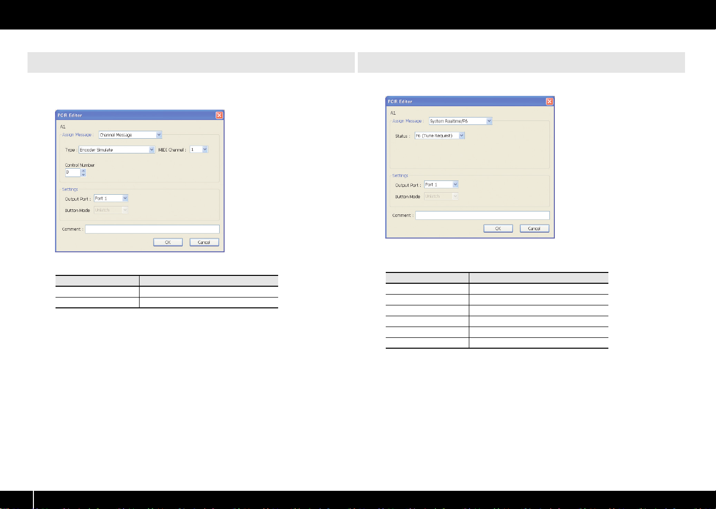
Encoder Simulate [Bn cc 41] – [Bn cc 01]
Assign a function that simulates a rotary encoder.
fig.EditorEncoder.eps_35
You can specify the following parameters for Encoder Simulate.
Item
MIDI Channel
Control Number Controller number [cc]
* This can be assigned to a button, but will not do anything.
MIDI channel [n]
Content
System Realtime/F6 [F6/F8/FA/FB/FC/FF]
Assign a system realtime message or F6 (Tune Request).
fig.EditorSR.eps_35
For System Realtime/F6, use the Status field to choose the message you want to
assign.
Item
F6
F8 Timing clock
FA Start
FB Continue
FC Stop
FF System reset
Tune request
Content
28
Page 29
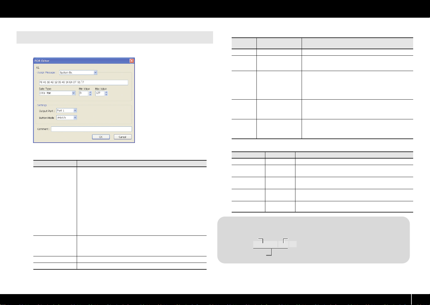
System Ex. [F0...F7]
Assign a system exclusive message (System Ex.). You can enter up to twenty-four bytes.
fig.EditorSysEx.eps_35
Using PCR Editor
Table 1: Special characters used in the message entry field
Special
character
DT
SS
S1/S2
?n
?x
Explanation Details
Data insertion location
Beginning of check-
sum calculation
Checksum insertion
location and type
Channel (? is any value between 0–7)
Block number (? is any
value between 0–7)
If you use the automatic checksum calculation function, use
this special character to specify the point at which checksum
calculation is to begin.
If you use the automatic checksum calculation function, use
this special character to specify the point at which the checksum is to be inserted, and its type.
S1: The most common type, used by Roland and other man-
ufacturers.
S2: Choose this if a method other than S1 is used.
If you want a channel number to be inserted in the exclusive
message, use this special character to specify its location
and the upper four bits (a fixed value of 0–7). The current
channel of the PCR will be inserted in the channel section.
If you want a GS block number to be inserted in the exclusive
message, use this special character to specify its location and
the upper four bits (a fixed value of 0–7). The current channel
of the PCR will converted into the block number and inserted.
You can specify the following parameters for System Ex.
Item
You can enter a system exclusive message of up to twenty-four bytes.
Enter each byte as a hexadecimal value separated by a single-byte
space.
The following limitations apply to the input.
* The message must begin with “F0” and end with “F7.”
Message entry field
Data Type
Min Value Lower limit of the data value
Max Value Upper limit of the data value
* You cannot include more than one exclusive message.
* You cannot include messages other than an exclusive
message.
You can enter variable data or a checksum using the special characters described in
try field
to specify the type of data.
If you’ve used the special character “DT” in the message entry field,
use this to specify the type of data to be inserted at that location. For
the types of data that can be specified, refer to
you can specify in the Data Type field
Table 1: Special characters used in the message en-
. If you use the special character “DT,” use the Data Type field
Content
Table 2: Types of data
.
Table 2: Types of data you can specify in the Data Type field
Data type
DT0: 7-bit
DT1: 4-bit/4-bit 2 bytes
DT2: 7-bit/7-bit
(MSB/LSB)
DT3: 7-bit/7-bit
(LSB/MSB)
DT4: 4-bit/
4-bit/4-bit/4-bit
Data length Target of the specified Min Value / Max Value
1 byte Specifies the range of the data itself (0–127)
Specifies the range of the first byte (0–15)
* The second byte is fixed at 0–15
2 bytes
2 bytes
4 bytes
Specifies the range of the MSB (0–127)
* The LSB is fixed at 0–127
Specifies the range of the MSB (0–127)
* The LSB is fixed at 0–127
Specifies the range of change (0–255) between the negative direction (Min) and the positive direction (Max), centered on 8000h.
Example of input
Roland GS TVF CUTOFF FREQ
Block number
F0 41 10 42 12 SS 40 1x 32 DATA SUM F7
Address Data Checksum
Calculation range for checksum
One byte
1. Enter the following in the message entry field.
F0 41 10 42 12 SS 40 1X 32 DT S1 F7
2.
In the Data Type field, choose “DT0.” Specify the
Min Value as “0” and the Max Value as “127.”
29
Page 30
Using PCR Editor
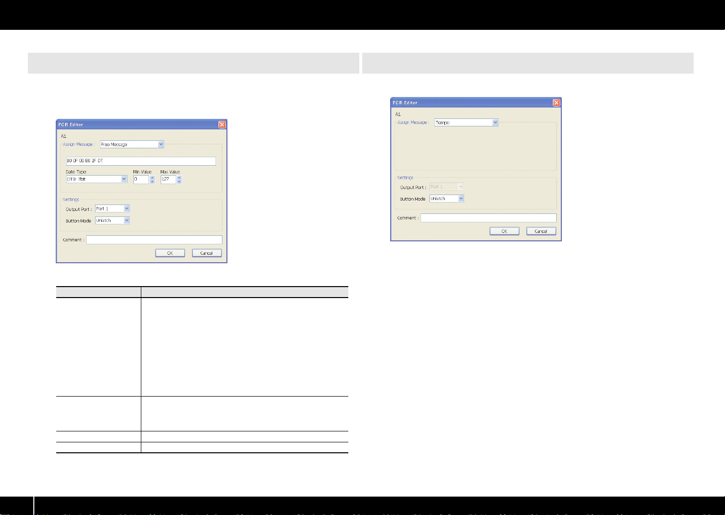
Free Message [...]
Assign a MIDI message.
You can enter up to twenty-four bytes. You may assign more than one MIDI message
if desired.
fig.EditorFreeMessage.eps_35
You can specify the following parameters for Free Message.
Item
You can enter a MIDI message of up to twenty-four bytes. Enter
each byte as a hexadecimal value separated by a single-byte
space.
The following limitations apply to the input.
Message entry field
Data Type
Min Value Lower limit of the data value
Max Value Upper limit of the data value
* You can’t use a checksum.
* You can’t use a special character as the first byte.
You can also enter variable data using the special characters described in
field
Type field to specify the type of data.
If you’ve used the special character “DT” in the message entry
field, use this to specify the type of data to be inserted at that location. For the types of data that can be specified, refer to
2: Types of data you can specify in the Data Type field
Table 1: Special characters used in the message entry
(p. 29). If you use the special character “DT,” use the Data
Content
Tempo
Assign tempo control for transmitting MIDI Clock messages.
fig.EditorTempo.eps_35
There are no parameters to specify for Tempo.
Table
(p. 29).
30
Page 31

Using PCR Editor
31
Page 32

Playing (Play mode)
Use Play mode when you want to play the PCR’s keyboard or use its controllers to
control your software or sound module.
Broadly speaking, the PCR has two modes.
Mode
This is the mode in which you play the key-
Play mode
Edit mode (p. 41)
board and operate the controllers. MIDI
messages will be transmitted by each controller.
This is the mode in which you assign MIDI
messages to each controller, send or receive bulk data, or make system settings.
When you turn on the power, the PCR-300/500/800 will start up in Play mode.
To return from Edit mode (p. 41) back to Play mode, press the [EDIT] button or the
[CANCEL] button. In this case, any setting you had not completed will be discarded.
When you play the keyboard in Play mode, note messages will be transmitted,
causing your sound module to produce sound.
Go ahead and play
Set the PCR’s current channel (MIDI transmit channel).
1
Set the PCR’s MIDI transmit channel to match the MIDI receive channel of your sound
module.
You can set the MIDI transmit channel setting as described in
channel (MIDI transmit channel)
From the PCR, select a sound on your sound module.
2
You can select sounds as described in
34).
3
Play the PCR’s keyboard.
When you’ve finished making settings, play the keyboard in Play mode; MIDI
messages will be sent to your application.
* Since the PCR keyboard does not contain a sound generator, it can’t produce sound by itself.
Overview How selected
When you turn on the
power
When you exit Edit
mode
When you press the Edit
button
Selecting the current
(p. 33).
Selecting sounds (Program Change/Bank)
(p.
Convenient performance functions
Here we’ll explain some typical functions that are convenient for performance.
Purpose
When you move the bender lever to left or right, pitch bend mes-
Modify the pitch of the
currently sounding note
(Pitch Bend)
Apply change to the currently sounding note
(Modulation)
Switch the octave
(Octave Shift)
While playing the keyboard, you can move the bender lever toward the left to
lower the pitch, or toward the right to raise the pitch. This is called the pitch bend
effect. Pushing the lever away from yourself will apply vibrato. This is called the
modulation effect.
If you move the lever toward the left or right while pushing it away from yourself,
both effects will be applied simultaneously.
sages will be transmitted, causing the currently sounding note to
vary its pitch.
* The range of the pitch bend depends on the settings of the
sound module.
When you push the bender lever away from yourself, modulation
messages (CC#01) will be transmitted, causing a vibrato effect to
be applied to the sound
* The change that occurs in the sound depends on the settings of
the sound module.
You can press [OCTAVE -] or [OCTAVE +] to lower or raise the
pitch of the keyboard in one-octave steps (Octave Shift). Use this
when you want to shift the range of the keyboard upward or
downward.
When you press [OCTAVE -] once, the pitch will shift downward
by one octave. When you press it again, the pitch will shift downward by an additional octave. You can shift the octave in a range
of -4 (down) to 5 (up). Depending on the current octave shift status,
[OCTAVE -] or [OCTAVE +] will light. If you press [OCTAVE -] and
[OCTAVE +] simultaneously, the octave shift setting will be reset to
0, and the keyboard will return to its normal pitch range.
Pitch bend effect Modulation effect
Description
fig.PitchBend-e.eps
* The pitch bend range will depend
on the settings of the sound module.
* If you assign different MIDI
messages to the bender lever, the
pitch bend effect and modulation
effect will not be applied.
32
Page 33

Selecting the current channel (MIDI transmit channel)
Here’s how to specify the current channel, which will be used to transmit data
produced by playing the keyboard as well as other performance data.
What is the current channel?
The current channel is the MIDI transmit channel for the keyboard and bender lever.
* Each controller can have an independent transmit channel setting. However, if “OMNI” is on,
all messages will be transmitted on the current channel.
What is OMNI?
When you turn the OMNI setting on, all controllers will always transmit on the current
channel, regardless of the MIDI transmit channel that’s specified for each individual
controller.
Use the following procedure to turn OMNI on if you want changes in the current
channel to switch the MIDI transmit channel for the controllers as well.
1. Press the [EDIT] button so it’s lit.
Playing (Play mode)
MIDI channel
Here’s how to change the current channel (MIDI transmit channel).
fig.H-MIDI-Ch.eps
Press the [MIDI CHANNEL] button.
1
The [MIDI CHANNEL] button will light. The
display will indicate the current channel.
Use the VALUE knob to specify the desired
2
channel number.
This completes the current channel setting.
You can also change the current channel in the following way.
1. Press the [EDIT] button to make the [EDIT] button light.
The display will indicate “EDIT.”
2. Press the [MIDI CHANNEL] button. The [MIDI CHANNEL] button will light,
and the display will indicate the current channel setting.
3. Use controllers [A1]–[A8] or [B1]–[B2], or the VALUE knob to specify the
desired channel number.
4. Press the [ENTER] button.
2. Turn the VALUE knob to make the display indicate “OMNI.”
3. Press the [ENTER] button.
The display will indicate the current setting.
Controller Item Display Explanation
[A1 (0)]
[A2 (1)]
OMNI
OFF
OMNI
ON
Messages will be transmitted to the
channel and port specified for each
controller.
Messages will be transmitted to the
KEYBOARD PORT on the current
channel, regardless of the channel
and port settings of each controller.
4. Use the VALUE knob or controllers [A1 (0)]–[A2 (1)] to select On or Off as
the setting.
5. Press the [ENTER] button.
The [EDIT] button will go out, and you will return to Play mode.
33
Page 34

Playing (Play mode)
Selecting sounds (Program Change/Bank)
You can select sounds on your sound module from the PCR by transmitting Program
Changes.
To select sounds in a different bank, you must first use Bank mode to transmit a Bank
Select message to switch the bank. Then transmit a Program Change message.
The bank select message must be transmitted before the program change.
Program Change and Bank Select
MIDI allows you to combine program change and bank select messages to access
more than 128 sounds.
If you want to select a different sound within the same bank as the currently selected
sound, you can switch sounds simply by sending a program change message alone.
If you want to select a sound from a different bank, you’ll need to send the
appropriate bank number and program number. The bank number is sent using two
MIDI messages; control change 0 (MSB) and control change 32 (LSB). To make the
sound actually change, you must send messages in the order of the bank number
(MSB), the bank number (LSB), and finally the program number.
Program Change
Here’s how to transmit a program change message on the current channel (p. 33).
fig.H-PC.eps
1
Press the [PROGRAM CHANGE] button.
The [PROGRAM CHANGE] button will light.
The display will indicate the program change
number that was transmitted most recently.
Use the VALUE knob to specify the program
2
change number that you want to send.
The program change message has now been
sent.
34
You can also send a program change in the following way.
1. Press the [EDIT] button so it’s lit.
The display will indicate “EDIT.”
2. Press the [PROGRAM CHANGE] button. It will light, and the display will
indicate the program change number that was transmitted most recently.
3. Use controllers [A1]–[A8], [B1]–[B8], or the VALUE knob to specify the
program change number that you want to send.
4. Press the [ENTER] button.
Page 35

Bank Select
In order to switch the bank number, you’ll need to make system settings for “Value
Encoder” so that [USER] is assigned to “BANK SELECT LSB” or “BANK SELECT MSB.”
* For details on how to make this setting, refer to this page or
If “BANK SELECT LSB” or “BANK SELECT MSB” is assigned to the VALUE knob, you’ll
be able to transmit bank select (MSB, LSB) messages using the following procedure.
fig.H-User.eps
Press the [USER] button.
1
The [USER] button will light. The display will
indicate the bank select number that was most
recently transmitted.
2
Use the VALUE knob to specify the bank select
number that you want to send.
The bank select (MSB, LSB) data has now been
transmitted.
VALUE knob settings
Playing (Play mode)
(p. 80).
Assignments for the VALUE knob
Here’s how to assign “BANK SELECT LSB” or “BANK SELECT MSB” to the [USER]
button of the VALUE knob.
1. Press the [EDIT] button so it’s lit.
The display will indicate “EDIT.”
2. Press the [USER] button. It will light, and the display will indicate the
currently assigned parameter.
3. Use controllers [A2], [A3] or the VALUE knob to select either
“LSB” or “MSB,” and then press the [ENTER] button.
The [EDIT] button will go out, and you will return to Play mode.
35
Page 36

Playing (Play mode)
Selecting the Lower and Upper sounds
The PCR-300/500/800’s keyboard has two parts—Lower and Upper—and you can select different sounds for each part.
Selecting the Lower sound
The entire keyboard will play the Lower sound.
fig.Lower.eps_80
LOWER
1
Press the [LOWER] button so it’s lit.
2
Press the [PROGRAM CHANGE] button, and turn the VALUE knob. The Lower
sound will change.
When you play the keyboard, you’ll hear the sound you selected for the Lower part.
Lower and Upper
Use the [UPPER] button and [LOWER] button to switch between the Upper part and
Lower part.
When the [UPPER] button is lit, performance data from the keyboard (notes and
aftertouch), bender lever (pitch and modulation), and foot pedal, as well as program
change messages, will be transmitted on the current channel specified for the Upper
part.
Octave Shift settings can be made independently for each part, and will be
remembered while you’re performing.
* If MIDI messages are assigned to aftertouch or the bender lever, they will be transmitted on the
assigned MIDI channel, not on the current channel.
Selecting the Upper sound
The entire keyboard will play the Upper sound.
fig.Upper.eps
UPPER
1
Press the [UPPER] button so it’s lit.
2
Press the [PROGRAM CHANGE] button, and turn the VALUE knob. The Upper
sound will change.
When you play the keyboard, you’ll hear the sound you selected for the Upper part.
36
Page 37

Playing (Play mode)
Layering two sounds (Dual)
Dual lets you play both the Lower sound and Upper sound from the entire keyboard.
Dual
The entire keyboard will play both the Lower and Upper sounds.
fig.Dual.eps_80
UPPER
LOWER
Press the [DUAL/SPLIT] button several times to make it light.
1
* If you want to change the Upper sound, press the [UPPER] button.
Playing two sounds in combination (Split)
Split lets you specify a boundary between the Upper region and Lower region, and
play the Upper and Lower sounds separately using your right and left hands.
Split
Here’s how to specify the ranges for the Lower sound and Upper sound so that you
can play them separately using your left and right hands.
fig.Sprit.eps_80
UPPER
LOWER
1
Press the [DUAL/SPLIT] button several times to make it blink.
* If you want to change the Upper sound, press the [UPPER] button.
Setting the Split point
Here’s how to specify the Split point at which the Upper and Lower regions will be divided.
1. Press the [EDIT] button so it’s lit.
2. Press the [SPLIT] button so it’s lit.
3. Press the key that you want to be the leftmost key in the Upper region. The display will
indicate the key that you pressed.
4. Press the [ENTER] button.
This completes the split point setting.
2
4
1
3
UPPER
LOWER
37
Page 38

Playing (Play mode)
Employing performance dynamics (Velocity)
Normally, the velocity value of the transmitted notes will vary depending on how strongly you play the keyboard.
If desired, you can also specify a fixed velocity at which all notes will be transmitted regardless of how strongly you play the keyboard.
This is convenient when you want to record into your DAW software at a fixed velocity.
You can also adjust the sensitivity or velocity curve as desired.
Specifying a fixed velocity (Key Velocity)
If you want to use a fixed velocity, you’ll need to set the “VALUE ENCODER” system
setting for [USER] to “Key Velocity.”
* For details on how to make this setting, refer to the bottom of this page or to
(p. 80).
If “KEY VELOCITY” is assigned to the VALUE encoder, you can use the following
procedure to transmit bank select (MSB, LSB) messages.
fig.H-User.eps
1
Press the [USER] button.
The [USER] button will light. The display will
indicate the most recently transmitted velocity
value.
Use the VALUE knob to specify the velocity
2
value (tch, 1–127) that you want to transmit.
fig.D-tch.eps
* If the display indicates “tch,” the transmitted velocity will depend on how
strongly you play the keyboard.
VALUE knob settings
Changing the keyboard touch (Velocity Curve)
Refer to the system setting
Assigning the VALUE knob
Here’s how to change the VALUE knob’s [USER] button assignment to “Key Velocity.”
1. Press the [EDIT] button so it’s lit.
The display will indicate “EDIT.”
2. Press the [USER] button. It will light, and the display will indicate the
currently assigned parameter.
Keyboard Velocity Curve
(p. 72).
38
3. Use the VALUE knob to select “VEL,” and press the [ENTER]
button.
This completes the setting; you will return to Play mode.
Page 39

Playing (Play mode)
Sending the current value of all controllers (Snapshot)
You can set the controllers to the desired positions and then transmit their state as a
“snapshot.”
The snapshot function will transmit the current values of the controllers [R1]–[R9], [S1]–
[S9], and [H1]–[H2] in a single operation.
This is a convenient way to send control data to your DAW software. You can
use this to record initial values at the beginning of your song.
Snapshot
fig.H-SNAP.eps
Simultaneously press the [PRM MUTE] button
1
and OCTAVE [-] button.
The [PRM MUTE] ([ENTER]) button will blink.
Press the [ENTER] button.
2
The [PRM MUTE] button will blink several times.
This completes transmission of the snapshot.
Muting the controller values (PRM MUTE)
You can mute all controllers so that they will not transmit MIDI messages even if they
are moved.
If a parameter value is distant from the current physical position of a controller,
you can avoid an unwanted sudden jump in the value by using the [PRM MUTE]
button to mute the controllers before moving the controller to a position that’s
close to the current value.
PRM MUTE
fig.H-PRMMute.eps
Press the [PRM MUTE] button.
1
The [PRM MUTE] button will light, and the
display will indicate “P ON.”
fig.D-PRMOn.eps
Operate the controllers.
2
At this time, MIDI messages will not be transmitted when you move
the controllers.
fig.D-PRMOff.eps
3
Press the [PRM MUTE] button once again.
The [PRM MUTE] button will go out, and the display will indicate
“POFF.”
Now, when you move the controllers, MIDI messages will once again be transmitted.
39
Page 40

Playing (Play mode)
When “stuck notes” occur (Panic)
If you experience problems during operation such as notes on your sound module that
fail to turn off, or if something is wrong with the sound, you can use the Panic function
to fix the problem.
The Panic function will transmit All Sound Off, All Notes Off, and Reset All Controllers
messages on all channels.
Panic
fig.H-PANIC.eps
1
Simultaneously press the [EDIT] button and
[PRM MUTE] button.
The [PRM MUTE] ([ENTER]) button will blink.
2
Press the [ENTER] button.
The [EDIT] button and [PRM MUTE] button will
blink several times.
This completes execution of the Panic function.
40
Page 41

Settings (Edit mode)
The PCR-300/500/800 has a total of fifty controllers: [R1]–[R9], [S1]–[S9], [A1]–[A9], [B1]–[B9], [C1]–[C3], [L1]–[L4], [H1]–[H2], [P1]–[P2], [BEND], [MOD], and [AFTERTOUCH].
You can freely assign the MIDI message that will be transmitted by each of these controllers. You need to use Edit mode to make MIDI message assignments. This section explains how
to assign MIDI messages to the controllers using the PCR keyboard.
Alternatively, you can make these assignments using PCR Editor. For details, refer to
Assigning MIDI messages on the PCR keyboard
The following functions can be assigned to controllers. • If you want to assign a MIDI message to [AFTERTOUCH], press the [EDIT] button
Function
Note
Aftertouch
Control change
Display Refer to
Note assign
Aftertouch assign
Control change assign
(p. 42)
(p. 44)
(p. 46)
Using PCR Editor
• If you’ve changed the controller settings, save the control map if you want to keep
• You can copy an assigned message to another controller, or cancel the
* If you want to assign a single-byte system message (system realtime message, tune request) or
(p. 14).
and then press down strongly on the keyboard or press the [AFTERTOUCH]
button.
your changes. If you turn off the power without saving, your changes will be lost.
(->
Saving a control map
assignment. For details, refer to
assignment (NO ASSIGN)
a freely specified message of up to twenty-four bytes, refer to
(p. 9))
(p. 67).
Copy assignment
(p. 66) or
Canceling an
System exclusive assign
(p. 55).
Program change
RPN
NRPN
System exclusive
(Sys Ex.)
Tempo
No Assign
Program change assign
RPN/NRPN assign
RPN/NRPN assign
System exclusive assign
Tempo assign
Canceling an assignment (NO
ASSIGN)
(p. 67)
(p. 48)
(p. 53)
(p. 53)
(p. 55)
(p. 52)
About Basic Editing and Advanced Editing
For assignments other than Tempo and No Assign, the PCR provides basic editing
and advanced editing. You can choose either basic or advanced editing as
appropriate for your needs.
Basic editing:
You can easily assign MIDI messages with the minimum of steps.
Advanced editing:
More steps will be required, but you’ll be able to specify more parameters to
assign more sophisticated MIDI messages.
41
Page 42

Settings (Edit mode)
Note assign
Here’s how to assign a note message to a controller. Note messages are used in a performance, and can also be used to control DAW software.
Editing
Basic editing
Advanced editing [A2 (1)] 1–16
Basic editing (->
fig.H-Edit.eps
Press the [EDIT] button so it’s lit.
1
fig.D-Edit.eps
The display will indicate “EDIT.”
fig.D-r1.eps
2
Slightly move the controller to which you want to assign a note
message.
If the controller is a button, press it.
The display will indicate the number of the selected controller.
3
Check the indication in the display, then press the [ENTER] button.
fig.D-Note.eps
Turn the VALUE knob to make the display indicate “NT” (Note
4
assign).
Press the [ENTER] button.
5
Controller Display
[A1 (0)] 1–16
Advanced editing 1
(p. 43))
MIDI transmit
channel
Note number Velocity Port Button mode Aftertouch
0–127
(00–7FH)
0–127
(00–7FH)
fig.D-NoteEdit0.eps
6
fig.D-ChannelSelect.eps
7
8
fig.D-NoteSelect.eps
9
10
11
12
100 (64H)
(fixed)
0–127
(00–7FH)
Turn the VALUE knob or press controller [A1 (0)] to get the “NT0”
indication for basic editing.
Press the [ENTER] button.
The display will indicate “CH- -.”
* The - - portion shows the currently specified value.
Enter the MIDI transmit channel.
Use the VALUE knob or controller [A1 (0)]–[B2 (9)] to specify the desired channel.
Press the [ENTER] button.
The display will indicate “N- -.”
* The - - portion shows the currently specified value.
Enter the note number. Use the VALUE knob or controller [A1]–
[A8] and [B1]–[B8] to specify the desired note number.
Press the [ENTER] button.
If the controller is [A1]–[A9], [B1]–[B9], [C1]–[C3], [L1]–[L4], or [P1], specify the
button mode (p. 64).
PORT1
(fixed)
PORT1,
PORT2,
PORT1+2
Unlatch/Latch OFF (fixed)
Unlatch/Latch
OFF,
Channel Pressure,
Polyphonic Key Pressure
42
Page 43

Settings (Edit mode)
Advanced editing 1
In Note Assign advanced editing 1, you can also specify the velocity value in
addition to the items in basic editing.
1. Press the [EDIT] button so it’s lit.
2. Slightly move the controller to which you want to assign a note
message.
If the controller is a button, press it.
The display will indicate the number of the selected controller.
3. Check the indication in the display, then press the [ENTER] button.
4. Make the display indicate “NT” (Note assign).
5. Press the [ENTER] button.
6. Turn the VALUE knob or press controller [A2 (1)] to make the display
indicate “NT1.”
7. Press the [ENTER] button.
The display will indicate “CH- -.”
* The - - portion shows the currently specified value.
8. Enter the MIDI transmit channel.
9. Press the [ENTER] button.
The display will indicate “N- -.”
* The - - portion shows the currently specified value.
10. Enter the note number.
11. Press the [ENTER] button.
The display will indicate “V- - -.”
* The - - - portion shows the currently specified value.
12. Enter the velocity value.
If the controller is [A1]–[A9] or [B1]–[B9], selecting “tch” will transmit a
velocity value that corresponds to the force with which you pressed the
pad.
13. Press the [ENTER] button.
The display will indicate “P- -” (MIDI output port).
* The - - portion shows the currently specified value.
14. Specify the MIDI output port.
(-> Port setting (p. 65))
15. If the controller is [A1]–[A9], [B1]–[B9], [C1]–[C3], [L1]–[L4], or [P1],
specify the button mode (p. 64).
16. If the controller is [A1]–[A9] or [B1]–[B9], specify the aftertouch
setting.
AFTERTOUCH OFF
CHANNEL
PRESSURE
POLYPHONIC KEY
PRESSURE
Aftertouch output will be disabled.
Channel pressure messages
will be transmitted.
Polyphonic key pressure messages will be transmitted.
* If you assign a note message to [S1]–[S9], [R1]–[R9], or [P2], moving the controller to the maximum position will transmit a note message with the specified velocity value. Slightly lowering the controller from
the maximum position will transmit a note message with a velocity of 0.
* If you assign a note message to [A1]–[A9], [B1]–[B9], [C1]–[C3], [L1]–[L4], or [P1], turning the controller on will transmit a note message with the specified velocity value.
Turning the controller off will transmit a note message with a velocity value of 0.
43
Page 44

Settings (Edit mode)
Aftertouch assign
Here’s how to assign an aftertouch message to a controller.
Edit
Basic editing
Advanced editing 1 [A2 (1)] Channel Pressure 1–16
Advanced editing 2 [A3 (2)] Polyphonic Key Pressure 1–16 0–127 (00–7FH)
Advanced editing 3 [A4 (3)] Polyphonic Key Pressure 1–16
Basic editing (->
fig.H-Edit.eps
1
Press the [EDIT] button so it’s lit.
Controller Display Content
[A1 (0)] Channel Pressure 1–16 0–127 (00–7FH)
Advanced editing 1–3
(p. 45))
MIDI transmit
channel
fig.D-AfterEdit0.eps
6
Turn the VALUE knob or press controller [A1 (0)] to get the “AT0”
Value range Port Button mode
You can specify an
upper and lower limit
You can specify an
upper and lower limit
indication (basic editing).
fig.D-ChannelSelect.eps
7
Press the [ENTER] button.
The display will indicate “CH- -.”
* The - - portion shows the currently specified value.
8
fig.D-Edit.eps
The display will indicate “EDIT.”
fig.D-r1.eps
Slightly move the controller to which you want to assign aftertouch.
2
If the controller is a button, press it.
Enter the channel.
Use the VALUE knob or controllers [A1 (0)]–[B2 (9)] to specify the desired channel.
9
Press the [ENTER] button.
10
As appropriate for the controller type, specify the button mode (p. 64).
The display will indicate the controller number you selected.
PORT1
(fixed)
PORT1,
PORT2,
PORT1+2
PORT1
(fixed)
PORT1,
PORT2,
PORT1+2
Unlatch, Latch,
Increase
Unlatch, Latch,
Increase
Unlatch, Latch,
Increase
Unlatch, Latch,
Increase
44
3
Check the indication in the display, then press the [ENTER] button.
fig.D-AfterEdit.eps
4
Turn the VALUE knob to make the display indicate “AT.”
Press the [ENTER] button.
5
Page 45

Settings (Edit mode)
Advanced editing 1–3
In Aftertouch Assign advanced editing 1, you can specify an upper and lower limit
for the aftertouch data as well as edit the basic editing items. In advanced editing 2
and 3, you can also specify note aftertouch data (Polyphonic Key Pressure) instead
of a channel.
1. Press the [EDIT] button so it’s lit.
2. Slightly move the controller to which you want to assign aftertouch. If the
controller is a button, press it. The display will indicate the controller
number you selected.
3. Check the indication in the display, then press the [ENTER] button.
4. Turn the VALUE knob to make the display indicate “AT.”
5. Press the [ENTER] button.
6. Turn the VALUE knob or press controller [A2 (1)]–[A4 (3)] to make the
display indicate “AT1,” “AT2,” or “AT3.”
7. Press the [ENTER] button.
8. Enter the channel.
9. Press the [ENTER] button.
10. If you’re using advanced editing 2 or advanced editing 3, enter a note
number and press the [ENTER] button.
11. If you’re using advanced editing 1 or 3, specify an upper limit and lower
limit as described in Specifying the value range (upper/lower limits) (p.
45).
12. If you’re using advanced editing 1 or 3, specify the output port.
(-> Port setting (p. 65))
13. According to the controller type, set the button mode (p. 64).
Specifying the value range (upper/lower limits)
If you’re using the PCR keyboard to assign MIDI messages (p. 41) in Edit mode, and
you’ve selected a mode that allows you to specify the range of the value, you’ll need
to set the maximum and minimum value.
1. The readout should be as shown.
2. Use the VALUE knob or controllers [A1]–[A8] and [B1]–
[B8] to specify the upper value limit.
3. Press the [ENTER] button.
4. The readout should be as shown.
5. Use the VALUE knob or controllers [A1]–[A8] and [B1]–
[B8] to specify the lower value limit.
6. Press the [ENTER] button.
45
Page 46

Settings (Edit mode)
Control change assign
Here’s how to assign a control change message to a controller.
Edit
Basic editing
Advanced editing 1 [A2 (1)] 1–16
Advanced editing 2 [A3 (2)] 1–16
Controller Display
[A1 (0)] 1–16
Basic editing (-> Advanced editing (p. 47))
fig.H-Edit.eps
1
Press the [EDIT] button so it’s lit.
fig.D-Edit.eps
The display will indicate “EDIT.”
fig.D-r1.eps
2
Slightly move the controller to which you want to assign a control
change message.
If the controller is a button, press it.
The display will indicate the number of the controller you selected.
3
Check the indication in the display, then press the [ENTER] button.
fig.D-CC.eps
Turn the VALUE knob to make “CC” appear.
4
Press the [ENTER] button.
5
MIDI transmit
channel
Control number Value range Port Button mode
0–127
(00–7FH)
0–127
(00–7FH)
0–127
(00–7FH)
fig.D-CCEdit0.eps
6
Turn the VALUE knob or press controller [A1 (0)] to select the basic
0–127 (00–7FH)
You can specify an
upper and lower limit
Simulates a rotary
encoder
PORT1
(fixed)
PORT1,
PORT2,
PORT1+2
PORT1,
PORT2,
PORT1+2
Unlatch, Latch,
Increase
Unlatch, Latch,
Increase
—
editing “CC0” indication.
fig.D-ChannelSelect.eps
7
Press the [ENTER] button.
The display will indicate “CH- -.”
* The - - portion shows the currently specified value.
8
Enter the channel.
Use the VALUE knob or controllers [A1 (0)]–[B2 (9)] to specify the desired channel.
fig.D-NoteSelect.eps
9
Press the [ENTER] button.
The display will indicate “N- - -.”
* The - - - portion shows the currently specified value.
10
Enter the control change number.
Use the VALUE knob or controllers [A1]–[A8] and [B1]–[B8] to specify the desired
control number.
11
Press the [ENTER] button.
12
As appropriate for the type of controller, make button mode settings (p. 64) or
virtual center click settings (p. 65).
46
Page 47

Settings (Edit mode)
Advanced editing 1
In control change assign advanced editing 1, you can specify an upper and lower
limit for the control change data, in addition to setting the items available in basic
editing.
1. Press the [EDIT] button so it’s lit.
2. Slightly move the controller to which you’re assigning a control change
message. If the controller is a button, press it.
The display will indicate the controller number.
3. Check the indication in the display, then press the [ENTER] button.
4. Turn the VALUE knob to make the display indicate “CC.”
5. Press the [ENTER] button.
6. Turn the VALUE knob or press controller [A2 (1)] to make “CC1” appear.
7. Press the [ENTER] button.
8. Enter the channel.
9. Press the [ENTER] button.
10. Enter the control change number.
11. Press the [ENTER] button.
12. Specify the range of values.
(-> Specifying the value range (upper/lower limits) (p. 45))
13. Specify the output port.
(-> Port setting (p. 65))
14. According to the type of controller, make button mode settings (p. 64) or
virtual center click settings (p. 65).
Advanced editing 2
In advanced editing 2, you can simulate the operation of a typical rotary encoder. If
this is assigned to a controller, moving the controller to the right of (or above) the
center position will produce the same result as turning the encoder clockwise.
Similarly, moving it to the left of (or below) the center position will produce the same
result as turning the encoder counterclockwise. As the controller position moves
farther away from the center, the result will be the same as turning the rotary encoder
more rapidly.
You can assign this advanced editing 2 function to a button, but it will not
operate.
1. Press the [EDIT] button so it’s lit.
2. Slightly move the controller to which you’re assigning a control change
message. If the controller is a button, press it.
The display will indicate the controller number.
3. Check the indication in the display, then press the [ENTER] button.
4. Turn the VALUE knob to make the display indicate “CC.”
5. Press the [ENTER] button.
6. Turn the VALUE knob or press controller [A3 (2)] to make “CC2” appear.
7. Press the [ENTER] button.
8. Enter the channel.
9. Press the [ENTER] button.
10. Enter the control change number.
11. Press the [ENTER] button.
12. Specify the output port.
(-> Port setting (p. 65))
47
Page 48

Settings (Edit mode)
Program change assign
Here’s how to assign a program change message to a controller.
Edit
Basic editing
Controller Display
[A1 (0)] 1–16 — —
MIDI transmit
channel
Bank MSB Bank LSB Value range Port
0–127
(00–7FH)
PORT 1
(fixed)
Advanced editing 1 [A2 (1)] 1–16 — —
Advanced editing 2 [A3 (2)] 1–16
Advanced editing 3 [A4 (3)] Current channel — — PC DEC
Advanced editing 4 [A5 (4)] Current channel — — PC INC
Basic editing (->
fig.H-Edit.eps
1
Press the [EDIT] button so it’s lit.
Advanced editing 1, 2
(p. 50),
Advanced editing 3 and 4
0–127
(00–7FH)
(p. 51))
fig.D-PC.eps
4
Turn the VALUE knob to make “PC” appear.
5
Press the [ENTER] button.
fig.D-PCEdit0.eps
Turn the VALUE knob or press controller [A1 (0)] to select the basic
6
0–127
(00–7FH)
editing “PC0” indication.
fig.D-ChannelSelect.eps
Press the [ENTER] button.
fig.D-Edit.eps
The display will indicate “EDIT.”
fig.D-r1.eps
2
Slightly move the controller to which you want to assign a program
change message.
7
The display will indicate “CH- -.”
* The - - portion shows the currently specified value.
Enter the channel. Use the VALUE knob or controller [A1 (0)]–[B2 (9)] to specify
8
the desired channel.
If the controller is a button, press it.
The display will indicate the number of the controller you selected.
You can specify an
upper and lower limit
0–127
(00–7FH)
PORT 1
(fixed)
PORT 1,
PORT 2,
PORT 1+2
PORT 1
(fixed)
PORT 1
(fixed)
48
3
Check the indication in the display, then press the [ENTER] button.
Page 49

fig.D-NoteSelect.eps
Press the [ENTER] button.
9
The display will indicate “N- -.”
* The - - portion shows the currently specified value.
10
Use the VALUE knob or controllers [A1]–[A8] and [B1]–[B8] to specify the
desired program number.
Press the [ENTER] button.
11
If you’ve assigned this basic editing function to [R1]–[R9], [S1]–[S9], or [P2], moving
the controller to the maximum position will transmit the specified program change
message.
Settings (Edit mode)
49
Page 50

Settings (Edit mode)
Advanced editing 1, 2
Program Change Assign advanced editing 1 lets you specify an upper limit and lower limit for the program change message. Advanced editing 2 lets you transmit Bank LSB/LSB
settings along with the program change.
1. Press the [EDIT] button so it’s lit.
2. Slightly move the controller to which you want to assign a program change message. If the controller is a button, press it.
The display will indicate the number of the controller you selected.
3. Check the indication in the display, then press the [ENTER] button.
4. Turn the VALUE knob to make “PC” appear.
5. Press the [ENTER] button.
Advanced editing 1 —Specifying the value range—
6. Turn the VALUE knob or press controller [A2 (1)] to select the
advanced editing “PC1” indication.
7. Press the [ENTER] button.
8. Enter the channel.
9. Press the [ENTER] button.
10. Specify the range of values.
(-> Specifying the value range (upper/lower limits) (p. 45))
Advanced editing 2 —Transmitting a bank select—
6. Turn the VALUE knob or press controller [A3 (2)] to select the
advanced editing “PC2” indication.
7. Press the [ENTER] button.
8. Enter the channel.
9. Press the [ENTER] button.
10. Enter the bank select MSB (CC#00). Use the VALUE
knob or controllers [A1]–[A8] and [B1]–[B8] to specify
the desired MSB.
* The - - - portion shows the currently specified value.
11. Press the [ENTER] button.
12. Enter the bank select LSB (CC#32). Use the VALUE knob
or controllers [A1]–[A8] and [B1]–[B8] to specify the
desired LSB.
* The - - - portion shows the currently specified value.
13. Press the [ENTER] button.
14. Enter the program number.
15. Press the [ENTER] button.
16. Specify the output port. (-> Port setting (p. 65))
50
Page 51

Settings (Edit mode)
Advanced editing 3 and 4
Advanced editing 3 lets you assign the program change decrement function (PC
DEC) to a controller.
Advanced editing 4 lets you assign the program change increment function (PC INC)
to a controller.
1. Press the [EDIT] button so it’s lit.
2. Slightly move the controller to which you want to assign PC DEC or PC
INC. If the controller is a button, press it.
The display will indicate the number of the controller you selected.
3. Check the indication in the display, then press the [ENTER] button.
4. Turn the VALUE knob to make “PC” appear.
5. Press the [ENTER] button.
6. Turn the VALUE knob or press controller [A4 (3)] or [A5 (4)] to get “PC3”
or “PC4” to appear in the display.
7. Press the [ENTER] button.
Program change decrement function (PC DEC)
This lets you transmit a program change that is one less than the most recently
transmitted program change number.
Program change increment function (PC INC)
This lets you transmit a program change that is one greater than the most recently
transmitted program change number.
The PC DEC and PC INC are transmitted on the current channel (p. 33) in the same
way as the program change (p. 34). The display will show the value that is actually
transmitted.
* By “most recently transmitted program change number,” we mean the value that was last
transmitted by the advanced editing 3 and 4 or program change functions (p. 34).
* Program changes transmitted by the basic editing or advanced editing 1 and 2 functions have
no effect on PC DEC or PC INC.
51
Page 52

Settings (Edit mode)
Tempo assign
You can assign a controller to adjust the speed of the F8 clock (20–250).
* In order to transmit F8 clock, the F8 clock setting must be “ON.” (->
fig.H-Edit.eps
1
Press the [EDIT] button so it’s lit.
fig.D-Edit.eps
The display will indicate “EDIT.”
fig.D-r1.eps
2
Slightly move the controller to which you want to assign Tempo.
If the controller is a button, press it.
The display will indicate the number of the controller you selected.
3
Check the indication in the display, then press the [ENTER] button.
fig.D-Tempo.eps
4
Turn the VALUE knob to make “TMP” appear.
F8 Clock On/Off
(p. 70))
52
Press the [ENTER] button.
5
Set the button mode (p. 64) as appropriate for the type of controller.
6
* For a button, the On position specifies the maximum value (250) and the Off position specifies
the minimum value (20).
Page 53

RPN/NRPN assign
You can assign an RPN or NRPN to a controller.
Settings (Edit mode)
Edit
Basic editing
Advanced editing [A2 (1)]
Basic editing (->
fig.H-Edit.eps
Press the [EDIT] button so it’s lit.
1
fig.D-Edit.eps
The display will indicate “EDIT.”
fig.D-r1.eps
Slightly move the controller to which you want to assign an RPN or
2
NRPN message.
If the controller is a button, press it.
The display will indicate the number of the controller you selected.
Check the indication in the display, then press the [ENTER] button.
3
fig.D-RPN.eps
4
Turn the VALUE knob to make “RP” appear.
* If you want to assign an NRPN, make “NP” appear. The rest of the
procedure is the same as for RPN.
Advanced editing 1
Controller Display
[A1 (0)] 0–127 (00–7FH) Not transmitted PORT 1
(p. 54))
Range of data entry MSB
fig.D-RPNEdit0.eps
6
fig.D-ChannelSelect.eps
7
8
9
fig.D-MSBSelect.eps
10
11
fig.D-LSBSelect.eps
12
(CC#6)
You can specify the upper
and lower limits
Turn the VALUE knob or press controller [A1 (0)] to select the basic
editing “RP0” indication.
Press the [ENTER] button.
“CH- -” will be blinking in the display.
* The - - portion shows the currently specified value.
Enter the channel. Use the VALUE knob or controllers [A1 (0)]–[B2 (9)] to specify
the desired channel.
Press the [ENTER] button.
Use the VALUE knob or controllers [A1 (0)]–[B2 (9)] to specify the
desired RPN MSB (CC#101) or NRPN MSB (CC#99).
* The - - portion shows the currently specified value.
Press the [ENTER] button.
Use the VALUE knob or controllers [A1 (0)]–[B2 (9)] to specify the
desired RPN LSB (CC#100) or NRPN LSB (CC#98).
* The - - portion shows the currently specified value.
Range of data entry LSB
(CC#38)
0–127 (00–7FH)
Port
PORT 1,
PORT 2,
PORT 1+2
5
Press the [ENTER] button.
13
Press the [ENTER] button.
14
As appropriate for the type of controller, set the button mode (p. 64) or make
virtual center click settings (p. 65).
53
Page 54

Settings (Edit mode)
Advanced editing 1
RPN/NRPN advanced editing 1 lets you specify the upper limit and lower limit for
the data entry MSB (CC#6) of the transmitted RPN/NRPN message, in addition to
allowing you to make the settings described in basic editing.
1. Press the [EDIT] button so it’s lit.
2. Slightly move the controller to which you want to assign an RPN or NRPN
message. If the controller is a button, press it. The display will indicate the
number of the controller you selected.
3. Check the indication in the display, then press the [ENTER] button.
4. Turn the VALUE knob to make “RP” appear.
* If you want to assign an NRPN, make “NP” appear. The rest of the procedure is the
same as for RPN.
5. Press the [ENTER] button.
6. Turn the VALUE knob or press controller [A2 (1)] to select the “RP1”
indication.
7. Press the [ENTER] button.
8. Enter the channel.
9. Press the [ENTER] button.
10. Use the VALUE knob or controllers [A1]–[A8] and [B1]–[B8] to specify the
RPN MSB (CC#101) (or the NRPN MSB (CC#99)).
11. Press the [ENTER] button.
12. Use the VALUE knob or controllers [A1]–[A8] and [B1]–[B8] to specify the
RPN LSB (CC#100) (or the NRPN LSB (CC#98)).
13. Press the [ENTER] button.
14. Specify the range of the data entry MSB (CC#6).
(-> Specifying the value range (upper/lower limits) (p. 45))
15. Specify the output port.
(-> Port setting (p. 65))
16. As appropriate for the type of controller, set the button mode (p. 64) or
make virtual center click settings (p. 65).
54
Page 55

System exclusive assign
You can assign a system exclusive message to a controller.
Advanced editing 2 lets you assign a single-byte system message (system realtime message, tune request).
Advanced editing 3 and 4 let you freely assign a message of up to twenty-four bytes.
Edit Controller Display Content Value range Ending condition Remarks/Limitations
Settings (Edit mode)
Basic editing
Advanced editing 1 [A2 (1)] Sys Ex. message Can be specified Enter F7 First byte fixed at F0
Advanced editing 2 [A3 (2)] 1-byte system message — —
Advanced editing 3 [A4 (3)] Any MIDI message Range of initial settings Specified number of bytes [CHECKSUM] button is unavailable
Advanced editing 4 [A5 (4)] Any MIDI message Can be specified Specified number of bytes [CHECKSUM] button is unavailable
[A1 (0)] Sys Ex. message Range of initial settings Enter F7 First byte fixed at F0
[0–5, 7, 9, D, E], [DATA], and
[CHECKSUM] buttons are unavailable
System exclusive assign lets you automatically calculate the checksum, or insert variable data or a channel/block number into the message.
For system exclusive assign, the input mode (p. 64) will be Hexadecimal.
55
Page 56

Settings (Edit mode)
System exclusive assignment procedure
fig.H-Edit.eps
1
Press the [EDIT] button so it’s lit.
fig.D-Edit.eps
The display will indicate “EDIT.”
fig.D-r1.eps
2
Slightly move the controller to which you want to assign a system
exclusive message.
If the controller is a button, press it.
The display will indicate the number of the controller you selected.
3
Check the indication in the display, then press the [ENTER] button.
fig.D-SysEx.eps
4
Turn the VALUE knob to make “SE” appear.
5
Press the [ENTER] button.
fig.D-SysExEdit0.eps
6
Turn the VALUE knob or press controller [A1 (0)] to display the
basic editing “SE0” indication.
* If you want to select advanced editing, press a controller [A2 (1)]–[A5 (4)]
to display the “SE1”–”SE4” indication.
Using basic editing or advanced editing 1
fig.D-F0.eps
The first byte “F0” of the system exclusive message (the beginning
status) will blink. (This “F0” byte cannot be changed.)
Verify that the display is correct, and press the [ENTER] button.
8
Use the VALUE knob or controllers [A1]–[A8] and [B1]–[B8] to enter the second
9
byte.
10
Check the indication in the display, then press the [ENTER] button.
11
Enter the third and subsequent bytes in the same way.
When you’ve finished entering the message, use the controllers to enter “F” and
12
“7” as the final “F7” status (End Of Exclusive).
Press the [ENTER] button. If you’re using advanced editing 1, specify the upper
13
and lower value limits.
(->
Specifying the value range (upper/lower limits)
Specify the output port.
14
(->
Port setting
As appropriate for the type of controller, set the button mode (p. 64) or the virtual
15
center click setting (p. 65).
(p. 65))
(p. 45))
56
7
Press the [ENTER] button.
Now you can proceed to the basic editing/advanced editing 1 procedure.
For details on the actual assignments, refer to
examples
(p. 58).
System exclusive message assignment
Page 57

Settings (Edit mode)
Using advanced editing 2
fig.D-F.eps
The display will indicate “F-.”
* The – portion shows the currently specified value.
8
Use the VALUE knob or controllers [A7 (6)], [B1 (8)], [B3 (A)]–[B5
(C)], and [B8 (F)] to specify the system exclusive message.
9
Press the [ENTER] button.
Specify the output port.
10
(->
Port setting
(p. 65))
Using advanced editing 3 or 4
fig.D-LSBSelect.eps
The display will indicate “L- - -.”
* The - - - portion shows the currently specified value.
8
Use controllers [A1]–[A8] and [B1]–[B2] to enter the number of
bytes you’ll be entering, as a decimal number.
9
Press the [ENTER] button.
Use controllers [A1]–[A8] and [B1]–[B8] to enter the first byte.
10
Press the [ENTER] button.
11
12
Enter the second and subsequent bytes in the same way.
13
When you’ve entered the number of bytes you specified in step 8, the message
you entered will be checked to see whether it is a valid MIDI message. If there is
a problem, the display will indicate “ERR.”
Press the [ENTER] button and you’ll return to step 8. Enter the values once again.
14
If you’re using advanced editing 4, specify the upper and lower value limits.
(->
Specifying the value range (upper/lower limits)
15
Specify the output port. (->
16
As appropriate for the type of controller, set the button mode (p. 64) or the virtual
center click setting (p. 65).
Port setting
(p. 65))
(p. 45))
57
Page 58

Settings (Edit mode)
System exclusive message assignment examples
•
Specifying a checksum
•
Specifying the location of the data
•
Entering channel/block data
Specifying a checksum
The PCR-300/500/800 can automatically calculate a checksum within a system
exclusive message and insert the result of this calculation into the message. To use this
function, use the following procedure to specify the location at which the checksum
calculation should be inserted. You can also select the type of checksum.
For a specific example, refer to system exclusive assign
fig.D-css.eps
Press the [CHK SUM] (checksum) button before you enter the byte
1
that will begin the checksum calculation.
The display will indicate “CSS” (checksum start).
If you press the [CHK SUM] button once again, “CSS” will be cancelled.
Press the [ENTER] button.
2
Continue entering data.
3
fig.D-cs1.eps
4
Press the [CHK SUM] button at the location at which the checksum
should be inserted.
The display will indicate “CS1” (checksum type 1).
5
Press the [ENTER] button.
(p. 58)
(p. 60)
(p. 59)
Bend Pitch Control
(p. 63).
Checksum types
There are two types of checksums, as follows
Controller
[A1 (0)]
[A2 (1)]
Display Item Summary
CHECK SUM
TYPE1
CHECK SUM
TYPE2
The method used by Roland
and most other manufacturers
Methods other than Type 1
Switching the type
fig.Switch-cs12.eps
[CHK SUM]
[A1 (0)][A2 (1)]
[CHK SUM]
If you want to switch to Type 2, press controller [A2] after pressing the [CHK SUM]
button in step 4.
If you want to return to Type 1, press controller [A1]. You can also switch the setting
by turning the VALUE knob.
58
Page 59

Settings (Edit mode)
Specifying the location of the data
As described below, you can specify the location and type of the variable data to be inserted in the system exclusive message.
For basic editing and advanced editing 3, the range of data values will be the default range. For advanced editing 1 and advanced editing 4, it will be the range specified by the user.
For a specific example, refer to
Press the [DATA] button at the location where you want the variable data to be inserted.
1
The display will indicate “DT0.”
Use pads [0]–[4] to select the type of data.
2
Master Volume
(p. 62).
Data number
DT0
DT1 4bit/4bit 0H/0H–FH/FH
DT2 7bit/7bit (MSB/LSB) 00H/00H–7FH/7FH
DT3 7bit/7bit (LSB/MSB) 00H/00H–7FH/7FH
DT4 4bit/4bit/4bit/4bit 7H/FH/0H/1H–8H/0H/FH/FH
* In the case of DT1–DT4 (data that occupies two or more bytes), a data area will automatically be allocated for the following byte(s), and the display will indicate “-DT.” (This cannot be changed.)
Press the [ENTER] button.
3
Data type Default range Target of range setting
7bit 00H–7FH Specify the data range (00H–7FH) 04–45 (minimum 4H, maximum 45H)
Specify the range of the first byte (0H–FH).
Second byte is fixed at 0–FH.
Specify the range of the MSB (00H–7FH).
LSB is fixed at 00H–7FH.
Specify the range of the MSB (00H–7FH).
LSB is fixed at 00H–7FH.
Specify the range of negative and positive as 00H–
FFH centered at 8000H.
min
8000H
max
FFFF
Example (specified minimum
and maximum value)
0/0–D/F (minimum 0H, maximum DH)
23/00–68/7F (minimum 23H, maximum 68H)
00/23–7F/68 (minimum 23H, maximum 68H)
7/F/0/2–8/0/5/0 (minimum FEH, maximum 50H)
If you selected DT1 through DT4, the display will indicate “-DT.”
Press the [ENTER] button.
4
59
Page 60

Settings (Edit mode)
Entering channel/block data
If the system exclusive message contains a channel or GS block number, use the following procedure to specify the type and the value of the upper bits. A channel or block number
corresponding to the current channel (p. 33) will be inserted into the lower bits.
The block number is not actually a channel; it corresponds to the “part” of a GS sound module. On the PCR, it corresponds to the channel for the sake of convenience.
For a specific example, refer to system exclusive assign
Bend Pitch Control
(p. 63).
current channel
CH
BL 1 2 3 4 5 6 7 8 9 0 A B C D E F
1
At the location where you want the channel/block number to be inserted, press the [DATA] button several times to select “0CH” for the channel or “0BL” for the block.
fig.chbl.eps_70
[ DATA ] [DATA ]
* The - - portion shows the currently specified value.
2
Use controllers [A1]–[A8] to enter the value of the upper four bits.
1 2 3 4 5 6 7 8 9 10 11 12 13 14 15 16
0 1 2 3 4 5 6 7 8 9 A B C D E F
[ DATA ]
[ DATA ]
The “0” in the display will change to the number you enter.
3
Press the [ENTER] button.
60
Page 61

Examples of system exclusive message assignments
•
GM2 System On
•
Master Volume
•
Bend Pitch Control
Here are some specific examples of system exclusive messages.
GM2 System On
“F0 7E 7F 09 03 F7”
Let’s use basic editing mode to enter a GM2 System On system exclusive message.
(p. 61)
(p. 62)
(p. 63)
Settings (Edit mode)
1
Press the [EDIT] button so it’s lit.
The display will indicate “EDIT.”
Slightly move the controller to which you want to assign the system exclusive
2
message. If the controller is a button, press it.
The display will indicate the number of the controller you selected.
Check the indication in the display, then press the [ENTER] button.
3
4
Turn the VALUE knob to make “SE” appear.
5
Press the [ENTER] button.
6
Turn the VALUE knob to make “SE0” appear.
Check the indication in the display, then press the [ENTER] button.
7
The display will show the first byte “F0” (beginning status) of the system exclusive
message. (This cannot be changed.)
Check the indication in the display, then press the [ENTER] button.
8
Use controllers [A8 (7)] and [B7 (E)] to enter the second byte “7E.”
9
You can also use the VALUE knob to change the value.
Check the indication in the display, then press the [ENTER] button.
10
Use controllers [A8 (7)] and [B8 (F)] to enter the third byte “7F.”
11
You can also use the VALUE knob to change the value.
12
Check the indication in the display, then press the [ENTER] button.
In the same way, enter the fourth byte “09” and fifth byte “03.”
Finally, use controllers [B8 (F)] and [A8 (7)] to enter the ending status “F7.”
13
You can also use the VALUE knob to change the value.
Check the indication in the display, then press the [ENTER] button.
14
15
Specify the output port. (->
16
As appropriate for the type of controller, set the button mode (p. 64) or the virtual
center click setting (p. 65).
This completes the steps necessary to assign the GM2 System On message.
Port setting
(p. 65))
61
Page 62

Settings (Edit mode)
Master Volume
“F0 7F 7F 04 01 vL vM F7”
Since the data range of the Master Volume message is 00 00–7F 7F and there’s no need to specify this range, you can choose basic editing. Since the data format is two bytes in the
order of LSB MSB, choose “DT3” (p. 59) when inserting the data.
Press the [EDIT] button so it’s lit.
1
The display will indicate “EDIT.”
Slightly move the controller to which you want to assign the system exclusive
2
message. If the controller is a button, press it.
The display will indicate the number of the controller you selected.
Check the indication in the display, then press the [ENTER] button.
3
Turn the VALUE knob to make “SE” appear.
4
Press the [ENTER] button.
5
6
Turn the VALUE knob to make “SE0” appear.
7
Verify that the display is correct, then press the [ENTER] button.
The display will show the first byte “F0” (beginning status) of the system exclusive
message. (This cannot be changed.)
8
Check the indication in the display, then press the [ENTER] button.
9
Use controllers [A8 (7)] and [B8 (F)] to enter the second byte “7F.”
Check the indication in the display, then press the [ENTER] button.
10
In the same way, enter the third byte “7F,” fourth byte “04,” and fifth byte “01.”
11
Since the sixth byte is the data area, press the [DATA] button and then press
12
controller [A4 (3)].
The display will indicate “DT3.”
Because you selected “DT3” at the sixth byte, the seventh byte is automatically
14
allocated as the data area, and cannot be edited.
The display will indicate “-DT.”
Check the indication in the display, then press the [ENTER] button.
15
Use controllers [B8 (F)] and [A8 (7)] to enter the ending status “F7.”
16
17
Check the indication in the display, then press the [ENTER] button.
18
Specify the output port. (->
19
As appropriate for the type of controller, set the button mode (p. 64) or the virtual
center click setting (p. 65).
This completes the steps necessary to assign the Master Volume message.
Port setting
(p. 65))
62
Check the indication in the display, then press the [ENTER] button.
13
Page 63

Bend Pitch Control
The GS message Bend Pitch Control has a data range of 40H–58H (0–24 semitones),
so you should choose advanced editing 1, which lets you specify the region. Since the
data format is one byte, you should choose “DT0” (p. 59) when inserting the data.
fig.checksum-e.eps
Block number
One byte
F0 41 10 42 12 40 2x 10 DATA SUM F7
Address Data Checksum
Checksum calculation region
1
Press the [ENTER] button.
The display will indicate “EDIT.”
Slightly move the controller to which you want to assign the system exclusive
2
message. If the controller is a button, press it.
The display will indicate the number of the controller you selected.
3
Check the indication in the display, then press the [ENTER] button.
4
Turn the VALUE knob to make “SE” appear.
5
Press the [ENTER] button.
6
Turn the VALUE knob to make “SE1” appear.
7
Verify that the display is correct, then press the [ENTER] button.
The display will show the first byte “F0” (beginning status) of the system exclusive
message. (This cannot be changed.)
13
Check the indication in the display, then press the [ENTER] button.
Next, enter the sixth byte.
14
Since the seventh byte will have “2” as the upper bits and the block number as
15
the lower bits, press [DATA] three times.
The display will indicate “0BL.”
Press pad [2] to specify “2” as the upper bits.
16
The display will indicate “2BL.”
17
Check the indication in the display, then press the [ENTER] button.
18
Next, enter the eighth byte.
Since the ninth byte is the data area, press the [DATA] button.
19
The display will indicate “DT0.”
Check the indication in the display, then press the [ENTER] button.
20
21
Since the checksum will be inserted at the tenth byte, press the [CHK SUM]
button to specify the location at which the checksum will be inserted.
“CS1” (checksum type 1) will be blinking in the display.
22
Check the indication in the display, then press the [ENTER] button.
Use controllers [B8 (F)] and [A8 (7)] to enter the ending status of “F7.”
23
24
Check the indication in the display, then press the [ENTER] button.
25
Next, specify “58” as the upper limit of the data area.
Settings (Edit mode)
8
Check the indication in the display, then press the [ENTER] button.
9
Use controllers [A5 (4)] and [A2 (1)] to enter the second byte “41.”
Alternatively, you can use the VALUE knob to change the value.
10
Check the indication in the display, then press the [ENTER] button.
11
In the same way, enter the third byte, fourth byte, and fifth byte.
Since the checksum calculation region begins at the sixth byte, press the [CHK
12
SUM] button to specify the beginning of the checksum calculation region.
“CSS” (checksum start) will be blinking in the display.
Press the [ENTER] button.
26
27
Specify “40” as the lower limit of the data area.
Press the [ENTER] button.
28
Specify the output port. (->
29
30
As appropriate for the type of controller, set the button mode (p. 64) or the virtual
center click setting (p. 65).
This completes the steps necessary to assign the GS Bend Pitch Control message.
Port setting
(p. 65))
63
Page 64

Settings (Edit mode)
Input mode setting
When entering numeric values in modes other than Play mode, you can use either
Decimal input mode or Hexadecimal input mode.
Press the [DECIMAL] button if you want to use decimal input mode, or press the [HEX]
button if you want to use hexadecimal input mode.
* When you turn on the power, the PCR will start up in decimal input mode.
Decimal and hexadecimal values correspond as follows.
Decimal: 0–127
Hexadecimal: 00–7F
However, for MIDI channels and program changes, the correspondence is as
follows.
Decimal Hexadecimal
MIDI channel 1–16 00–0F
Program change 1–128 00–7F
Button mode setting
When using edit mode to assign MIDI messages on the PCR keyboard (p. 41), and
you’re assigning a message to a button, you’ll need to specify the way in which the
button is to operate (the button mode).
When you use a button as a controller, the maximum specified value will be
transmitted when you turn the button on, and the minimum value will be transmitted
when you turn the button off.
1. Turn the [VALUE] dial to select either Unlatch, Latch, or Increase mode.
Mode Display Summary
Unlatch
Latch
Increase
2. Press the [ENTER] button.
The button will turn on when pressed, and off when
released. The button will be lit while you hold it
down.
The button will alternately turn on or off each time
you press it. The button will light when an On signal
is transmitted, and will go out when an Off signal is
transmitted.
Each time you press the button, the value will increase by one. (If the minimum value is below the
maximum value, it will decrease by one.) When the
value reaches the maximum (or minimum), it will
“wrap around” to the minimum (or maximum) value.
The button will be lit only while you’re pressing it.
64
Page 65

Settings (Edit mode)
Virtual center click setting
When using edit mode to assign MIDI messages on the PCR keyboard (p. 41), and
you’re assigning a message to a knob [R1]–[R9] or slider [S1]–[S8], you’ll need to
specify whether the virtual center click will be on or off.
1. Turn the VALUE knob to select On or Off.
Mode Display Summary
Off
On
64
63 65
The PCR’s knobs and sliders do not have a “physical” center click.
However, by turning on the virtual center click, you can broaden the
region in the middle of the controller’s range for which the center value
0 127
will be produced.
2. Press the [ENTER] button.
The value will change smoothly from the
minimum to maximum.
The value will remain at the center value
(64) near the middle of the controller’s
range.
Port setting
When using edit mode to assign MIDI messages on the PCR keyboard (p. 41), and
you’ve selected advanced editing, you’ll need to specify the USB port from which the
message assigned to the controller will be transmitted when using a USB connection.
1. Turn the VALUE knob to select the port.
Port Display Summary
PORT 1 Messages will be sent to “EDIROL PCR 1.”
PORT 2 Messages will be sent to “EDIROL PCR 2.”
PORT 1+2
2. Press the [ENTER] button.
* For more about the ports, refer to What are MIDI ports? (p. 14).
* If you’re using the PCR with a MIDI connection, this setting is ignored.
Messages will be sent to “EDIROL PCR 1”
and “EDIROL PCR 2.”
65
Page 66

Settings (Edit mode)
Convenient functions
Copy assignment
A message assigned to a controller can be copied to another controller.
For example, if you want to assign similar functions to more than one controller, you can assign the desired MIDI message to one controller and copy the assignment to other controllers
for greater efficiency.
If you copy an assigned message between controllers of differing types (for example between a button and a knob), the results may be unexpected. For example, if a note message assigned
to a pad is copied to a knob, you won’t get the expected result.
If a rotary encoder simulation assigned to a knob is copied to a button, it will not operate.
fig.H-Edit.eps
Press the [EDIT] button so it’s lit.
1
fig.D-Edit.eps
The display will indicate “EDIT.”
Please be aware of the controller type and content of the message when copying MIDI message assignments.
66
fig.D-r1.eps
2
Select the copy-destination controller, and move it slightly. If it’s a
button, press it.
The display will indicate the controller number.
3
Check the indication in the display, then press the [ENTER] button.
fig.D-Copy.eps
4
Slightly move the copy-source controller. If it’s a button, press it.
“COPY” will be blinking in the display.
fig.D-s1.eps
Press the [ENTER] button.
5
The copy-source controller number will be blinking in the display.
6
Check the indication in the display, then press the [ENTER] button.
Page 67

Canceling an assignment (NO ASSIGN)
Here’s how to cancel the MIDI message assigned to a controller. If you’ve cancelled
the assignment, moving that controller will not transmit any MIDI message.
* If you cancel the MIDI message assignment for bender, modulation, aftertouch, hold (P1), or
expression (P2), these controllers will revert to controlling their original function. In such cases,
the current channel will be used as the MIDI transmit channel.
fig.H-Edit.eps
Press the [EDIT] button so it’s lit.
1
fig.D-Edit.eps
The display will indicate “EDIT.”
fig.D-r1.eps
2
Select the controller whose message assignment you want to
cancel, and move it slightly. If it’s a button, press it.
The display will indicate the controller number.
Settings (Edit mode)
3
Check the indication in the display, then press the [ENTER] button.
fig.D-NoAssign.eps
4
Turn the VALUE knob to get the “NOA” indication.
5
Press the [ENTER] button.
fig.D-yes.eps
“YES” will be blinking in the display; press the [ENTER] button
6
once again.
67
Page 68

System settings
Here’s how to make system settings for the PCR-300/500/800.
The system setting items are listed below.
Category Controller Display Item Contents Factory setting Procedure
[A1 (0)] F8 CLOCK ON/OFF Specifies whether F8 Clock will be transmitted. OFF p. 70
Clock
Keyboard
Pads
[A2 (1)]
[A3 (2)] F8 CLOCK PORT SET
[A4 (3)]
[A5 (4)] KEYBOARD PORT SET
[A6 (5)]
[A7 (6)] PAD VELOCITY CURVE
[A8 (7)]
F8 CLOCK DEFAULT
TEMPO
KEYBOARD VELOCITY
CURVE
KEYBOARD
AFTERTOUCH CURVE
PAD AFTERTOUCH
CURVE
If “F8 Clock On/Off” is on, this specifies the default tempo of the F8
clock. After the power is turned on, this tempo will be output until you
move the VALUE encoder to which TEMPO is assigned.
Specifies the port from which F8 Clock is transmitted when “F8 Clock
On/Off” is on.
Specifies the response curve for the velocity that is transmitted when
you play the keyboard.
Specifies the port from which the keyboard and bender lever will
transmit performance data.
Specifies the response curve for keyboard aftertouch. 1 p. 74
Specifies the response curve for the velocity that is transmitted when
you strike a pad controller [A1]–[A9] or [B1]–[B9].
Specifies the response curve for the aftertouch that is transmitted
when you press a pad controller [A1]–[A9] or [B1]–[B9].
120 p. 70
PORT 1 p. 71
1-MEDIUM p. 72
PORT 1 p. 74
1 p. 75
1 p. 75
68
Page 69

System settings
Category
MIDI
Control map
Controller
Other
Controller Display Item Contents Factory setting Procedure
[B1 (8)] MIDI I/F SWITCH
[B2 (9)]
[A2 (1)]
+
[A1 (0)]
[A2 (1)]
+
[A2 (1)]
[A2 (1)]
+
[A3 (2)]
[A2 (1)]
+
[A5 (4)]
[A2 (1)]
+
[A6 (5)]
[A2 (1)]
+
[A4 (3)]
[A2 (1)]
+
[A7 (6)]
MIDI MERGE
DESTINATION
ADVANCED DRIVER
SWITCH
USB UNIT NUMBER
STARTUP MEMORY
VALUE ENCODER Specifies the parameter that the VALUE knob will transmit. KEY VELOCITY p. 80
DYNAMIC MAPPING/
V-LINK
H-ACTIVITY ON/OFF
FACTORY RESET Returns the PCR-300/500/800’s settings to the factory-set condition. — p. 81
Specifies whether the MIDI connectors will be used as a MIDI interface.
Specifies the port that will be merged when the “MIDI MERGE” switch
is On.
Switches the driver operation mode.
* If you change this setting, the change will take effect the next time
you turn on the power.
This setting is for future expanded functionality. It is not currently
used.
Specifies which control map will be loaded at startup when the PCR
is powered up.
Specifies the function of the DYNAMIC MAPPING/V-LINK switch.
Turn this on if you’re using the PCR with certain applications (such as
Pro Tools LE). If this is On, “90 00 7F” will be transmitted from “PCR
2” at intervals of approximately 500 ms.
ON p. 76
PORT 1 p. 77
ON
0 —
CONTROL MAP
No. 0
DYNAMIC
MAPPING 0
OFF p. 81
p. 78
p. 79
p. 81
69
Page 70

System settings
Clock settings
F8 Clock On/Off
Here’s how to specify whether F8 Clock will be transmitted.
Press the [EDIT] button so it’s lit.
1
The display will indicate “EDIT.”
Use the VALUE knob to select “SYS,” and press the [ENTER] button.
2
Use the VALUE knob to select “SY00,” and press the [ENTER] button.
3
Use the VALUE knob or controllers [A1] and [A2] to turn F8 Clock on or off.
4
The display will indicate “ON” or “OFF.”
Press the [ENTER] button to return to Play mode.
5
F8 Clock Default Tempo
Here’s how to specify the initial tempo of the F8 Clock when “F8 Clock” is On. After
you turn on the power, this tempo will be transmitted until you move the VALUE knob
to which Tempo is assigned. (->
Press the [EDIT] button so it’s lit.
1
The display will indicate “EDIT.”
Use the VALUE knob to select “SYS,” and press the [ENTER] button.
2
Use the VALUE knob to select “SY01,” and press the [ENTER] button.
3
Use the VALUE knob to set the F8 Clock Default Tempo to a value within the 20–
4
250 range.
The display will indicate the value you specify.
Press the [ENTER] button to return to Play mode.
5
Tempo assign
(p. 52))
70
Page 71

F8 Clock Port Set
Here’s how to specify the port from which F8 Clock will be sent when “F8 Clock On/
Off” is On.
Press the [EDIT] button so it’s lit.
1
The display will indicate “EDIT.”
2
Use the VALUE knob to select “SYS,” and press the [ENTER] button.
Use the VALUE knob to select “SY02,” and press the [ENTER] button.
3
Use the VALUE knob or controllers [A1]–[A3] to specify the F8 Clock Port.
4
The display will indicate the port you specify.
Press the [ENTER] button to return to Play mode.
5
System settings
Controller
[A1 (0)]
[A2 (1)] PORT 2
[A3 (2)] PORT 1+2
Indication Setting Summary
PORT 1
The clock will be sent to “EDIROL
PCR 1.”
The clock will be sent to “EDIROL
PCR 2.”
The clock will be sent to “EDIROL
PCR 1” and “EDIROL PCR 2.”
71
Page 72

System settings
Keyboard settings
Keyboard Velocity Curve
Here’s how to specify how the velocity transmitted when you play the keyboard will
respond to your playing strength.
1
Press the [EDIT] button so it’s lit.
The display will indicate “EDIT.”
2
Use the VALUE knob to select “SYS,” and press the [ENTER] button.
Controller
[A1 (0)]
[A2 (1)] 1-MEDIUM The keyboard sensitivity will be normal.
[A3 (2)] 1-HEAVY You will need to play strongly in order to produce high velocity values (volumes).
[A4 (3)] 2-LIGHT
[A5 (4)] 2-MEDIUM The keyboard sensitivity will be normal.
[A6 (5)] 2-HEAVY You will need to play strongly in order to produce high velocity values (volumes).
Indication Setting Type of curve Keyboard sensitivity
1-LIGHT
1
These are the most typical velocity curves.
The volume will correspond to your keyboard playing strength in the most natural
way.
2
Compared to curve 1, these curves produce
greater volume change across the softly
played range of notes.
3
Use the VALUE knob to select “SY03,” and press the [ENTER] button.
Use the VALUE knob or controllers [A1]–[A8] and [B1]–[B4] to specify the
4
desired Keyboard Velocity Curve.
The display will indicate the curve you specify.
Press the [ENTER] button to return to Play mode.
5
You can produce high velocity values (volumes) even by playing the keyboard softly.
You can produce high velocity values (volumes) even by playing the keyboard softly.
72
Page 73

System settings
Controller
[A7 (6)]
[A8 (7)] 3-MEDIUM The keyboard sensitivity will be normal.
[B1 (8)] 3-HEAVY You will need to play strongly in order to produce high velocity values (volumes).
[B2 (9)] 4-LIGHT
[B3 (A)] 4-MEDIUM The keyboard sensitivity will be normal.
[B4 (B)] 4-HEAVY You will need to play strongly in order to produce high velocity values (volumes).
Indication Setting Type of curve Keyboard sensitivity
3-LIGHT
You can produce high velocity values (volumes) even by playing the keyboard softly.
3
These velocity curves produce less change
in response to variations in your playing
strength, making it easier for you to maintain a consistent playing volume.
You can produce high velocity values (volumes) even by playing the keyboard softly.
4
Compared to curve 1, these curves produce
greater volume change across the strongly
played range of notes.
73
Page 74

System settings
Keyboard Port Set
Here’s how to specify the port that will transmit performance data from the keyboard
and bender lever.
Press the [EDIT] button so it’s lit.
1
The display will indicate “EDIT.”
2
Use the VALUE knob to select “SYS,” and press the [ENTER] button.
Use the VALUE knob to select “SY04,” and press the [ENTER] button.
3
Use the VALUE knob or controllers [A1]–[A3] to specify the desired Keyboard
4
Port.
The display will show the setting you specified.
Press the [ENTER] button to return to Play mode.
5
Controller
[A1 (0)] PORT 1
[A2 (1)] PORT 2
[A3 (2)] PORT 1+2
Indication Setting Summary
Messages will be sent to
“EDIROL PCR 1.”
Messages will be sent to
“EDIROL PCR 2.”
Messages will be sent to
“EDIROL PCR 1” and
“EDIROL PCR 2.”
Keyboard Aftertouch Curve
Here’s how to specify the aftertouch response of the keyboard.
Press the [EDIT] button so it’s lit.
1
The display will indicate “EDIT.”
2
Use the VALUE knob to select “SYS,” and press the [ENTER] button.
Use the VALUE knob to select “SY05,” and press the [ENTER] button.
3
Use the VALUE knob or controllers [A1]–[A4] to specify the desired Keyboard
4
Aftertouch Curve.
The display will show the setting you specified.
Press the [ENTER] button to return to Play mode.
5
Controller
[A1 (0)]
[A2 (1)] 2
[A3 (2)] 3
[A4 (3)] 4
Indication Setting
1
Curve type
1
2
3
4
This is the most typical setting. It will produce the most
natural correspondence between the pressure you apply
to the keyboard and the aftertouch data that is produced.
Compared to curve 1, this allows aftertouch to be produced even with light
pressure on the keyboard.
This curve produces less aftertouch change in response
to pressure on the keyboard,
making it easier to perform
consistently.
Compared to curve 1, this
will produce aftertouch in response to strong pressure on
the keyboard.
Effect
74
Page 75

Pad settings
System settings
Pad Velocity Curve
Here’s how to specify how the velocity transmitted when you play the pad controllers
[A1]–[A9] and [B1]–[B9] will respond to your playing strength.
Press the [EDIT] button so it’s lit.
1
The display will indicate “EDIT.”
Use the VALUE knob to select “SYS,” and press the [ENTER] button.
2
Use the VALUE knob to select “SY06,” and press the [ENTER] button.
3
Use the VALUE knob or controllers [A1]–[A4] to specify the desired Pad Velocity
4
Curve.
The display will indicate the curve you specify.
Press the [ENTER] button to return to Play mode.
5
Controller
[A1 (0)]
[A2 (1)] 2
[A3 (2)] 3
[A4 (3)] 4
Indication
Setting
1
Curve type
1
2
3
4
This is the most typical setting. It will produce the most
natural correspondence between the force of your pad
strike and the change in volume.
Compared to curve 1, this allows more volume change to
be produced in the softer
range of pad strikes.
This curve produces less volume change in response to
your pad strikes, making it
easier to maintain a consistent volume.
Compared to curve 1, this
produces more volume
change in the stronger range
of pad strikes.
Effect
Pad Aftertouch Curve
Here’s how to specify the aftertouch response of the pads.
Press the [EDIT] button so it’s lit.
1
The display will indicate “EDIT.”
Use the VALUE knob to select “SYS,” and press the [ENTER] button.
2
Use the VALUE knob to select “SY07,” and press the [ENTER] button.
3
Use the VALUE knob or controllers [A1]–[A4] to specify the desired Pad
4
Aftertouch Curve.
The display will show the setting you specified.
Press the [ENTER] button to return to Play mode.
5
Controller
[A1 (0)]
[A2 (1)] 2
[A3 (2)] 3
[A4 (3)] 4
Indication
Setting
1
Curve type
1
2
3
4
Effect
This is the most typical setting. It will produce the most
natural correspondence between the pressure you apply
to the pad and the aftertouch
data that is produced.
Compared to curve 1, this allows aftertouch to be produced even with light
pressure on the pad.
This curve produces less aftertouch change in response
to pressure on the pad, making it easier to perform consistently.
Compared to curve 1, this
will produce aftertouch in response to strong pressure on
the pad.
75
Page 76

System settings
MIDI settings
MIDI I/F Switch
Here’s how to specify whether the MIDI connectors will be used as a MIDI interface.
1
Press the [EDIT] button so it’s lit.
The display will indicate “EDIT.”
2
Use the VALUE knob to select “SYS,” and press the [ENTER] button.
Controller
[A1 (0)]
[A2 (1)]
Indication Setting Summary
MIDI messages received by the PCR keyboard
OFF
will not be transmitted from the PCR. MIDI messages will be transmitted and received between
the PCR and the computer, or between the PCR
and the external MIDI device.
The MIDI connectors of the PCR keyboard will
operate as a MIDI interface. MIDI messages
from the computer that’s connected via USB to
ON
the PCR will be conveyed to the sound module
connected to the PCR’s MIDI OUT connector.
MIDI messages from the MIDI device connected
to the PCR’s MIDI IN connector will be conveyed to the computer.
3
Use the VALUE knob to select “SY08,” and press the [ENTER] button.
Use the VALUE knob or controllers [A1] or [A2] to specify the desired MIDI I/F
4
setting.
The display will show the setting you specified.
Press the [ENTER] button to return to Play mode.
5
MIDI I/F MODE OFF
MIDI OUT device
EDIROL PCR MIDI OUT
EDIROL PCR
MIDI IN device
EDIROL PCR MIDI IN
EDIROL PCR 1
EDIROL PCR 2
MIDI OUT device
EDIROL PCR MIDI OUT
EDIROL PCR
MIDI IN device
EDIROL PCR MIDI IN
EDIROL PCR 1
EDIROL PCR 2
USB
MIDI messages
MIDI I/F MODE ON
USB
MIDI messages
X
Bulk reception
X
PORT 1
PORT 2 /
Bulk transmission
Bulk reception
PORT 1
PORT 2 /
Bulk transmission
MIDI OUT
MIDI IN
MIDI OUT
MIDI IN
76
Page 77

MIDI Merge Destination
The PCR-300/500/800 has a MIDI MERGE switch. The MIDI Merge Destination setting specifies the port that will be merged when the MIDI MERGE switch is ON.
The MIDI Merge function is convenient when you’ve connected an external MIDI controller other than the PCR to the PCR’s MIDI IN connector. For example, you could connect another PCR,
and use one PCR to control your software synthesizer while using the other PCR to control your DAW software.
Press the [EDIT] button so it’s lit.
1
The display will indicate “EDIT.”
Use the VALUE knob to select “SYS,” and press the [ENTER] button.
2
Use the VALUE knob to select “SY09,” and press the [ENTER] button.
3
4
Use the VALUE knob or controllers [A1]–[A3] to specify the desired MIDI merge
destination.
The display will show the setting you specified.
5
Press the [ENTER] button to return to Play mode.
The MIDI MERGE switch and the MIDI Merge Destination
MIDI I/F MODE ON
Controller
[A1 (0)]
[A2 (1)] PORT 2
[A3 (2)] MIDI OUT
Indication Setting Summary
PORT 1
System settings
Messages from MIDI IN will be
merged with the PCR’s PORT 1.
Messages from MIDI IN will be
merged with the PCR’s PORT 2.
Messages from MIDI IN will be
merged with the PCR’s MIDI OUT.
MIDI OUT device
EDIROL PCR MIDI OUT
EDIROL PCR
MIDI IN device
X
EDIROL PCR MIDI IN
EDIROL PCR 1
EDIROL PCR 2
USB
MIDI messages
Bulk reception
PORT 1
PORT 2 /
Bulk transmission
MIDI OUT
PORT 1
PORT 2
PORT 2
OFF
ON
ON
MIDI MERGE DESTINATION
MIDI OUT
MIDI IN
MIDI MERGE switch
In this diagram, the MIDI MERGE switch is ON, and the MIDI Merge Destination is set to PORT 2, so the messages received at MIDI IN will be merged with the messages of PORT 2
and sent to the computer.
* If you turn the MIDI MERGE switch ON, no messages will be received if you’ve selected EDIROL PCR MIDI IN as the MIDI IN device on your computer.
77
Page 78

System settings
Advanced Driver Switch
Here’s how to switch ADVANCED DRIVER ON/OFF.
Normally, we recommend that you use ON.
* Changes you make to this setting will take effect the next time you turn on the power.
Press the [EDIT] button so it’s lit.
1
The display will indicate “EDIT.”
2
Use the VALUE knob to select “SYS,” and press the [ENTER] button.
Use the VALUE knob to select “SY10,” and press the [ENTER] button.
3
Use the VALUE knob or controllers [A1] or [A2] to specify the desired USB MIDI
4
driver type.
78
Controller
[A1 (0)]
[A2 (1)]
* FPT = Fast Processing Technology of MIDI Transmission
This makes effective use of the USB bandwidth depending on the amount of MIDI data being
sent, ensuring that MIDI data handling will always occur optimally.
5
Press the [ENTER] button to return to Play mode.
Indication Setting Summary
OFF
ON
Choose this setting if you want to
use the standard MIDI driver provided by your operating system.
Choose this setting if you want to
use FPT technology to allow highspeed MIDI transmission. We recommend that you normally use this
setting.
Page 79

Control map settings
Startup Memory
Here’s how to specify the control map that will be selected when you turn on the
power.
Press the [EDIT] button so it’s lit.
1
The display will indicate “EDIT.”
Use the VALUE knob to select “SYS,” and press the [ENTER] button.
2
Use the VALUE knob to select “SY12,” and press the [ENTER] button.
3
Use the VALUE knob or controllers [A1] or [A2] to choose CONTROL MAP No. 0
4
or LAST ACCESS MEMORY.
System settings
Controller
[A1 (0)]
[A2 (1)]
5
Press the [ENTER] button.
Indication Setting Summary
CONTROL
MAP No. 0
LAST
ACCESS
MEMORY
Control map number 0 will be loaded into current memory (p. 8) when
the PCR starts up.
The control map that you most recently called up or saved will be
loaded into current memory (p. 8)
when the PCR starts up.
79
Page 80

System settings
VALUE knob settings
VALUE encoder
Here’s how to specify the function that will be controlled by the VALUE knob when you press the [USER] button.
1
Press the [EDIT] button so it’s lit.
The display will indicate “EDIT.”
2
Use the VALUE knob to select “SYS,” and press the [ENTER] button.
3
Use the VALUE knob to select “SY14,” and press the [ENTER] button.
Use the VALUE knob or controllers [A1]–[A5] to choose the parameter that the
4
VALUE knob will transmit.
Press the [ENTER] button.
5
Controller
[A1 (0)]
[A2 (1)]
[A3 (2)]
[A4 (3)]
[A5 (4)]
As an alternate to the procedure described above, you can make this setting using the procedure below.
Indication Setting Summary Value range
The VALUE knob will specify the fixed velocity value. The PCR detects the force with which you
KEY VELOCITY
BANK LSB
BANK MSB
CONTROL
CHANGE
TEMPO
play the keyboard, and transmits this as the velocity, but if you use this function, the velocity will
be transmitted as the fixed value specified by the VALUE knob regardless of how strongly you
play the keyboard. Use this in cases where you want to eliminate dynamics from your playing.
The VALUE knob will specify the bank select LSB (CC#32).
The VALUE knob will specify the bank select MSB (CC#00).
The VALUE knob will specify a control change.
The VALUE knob will specify the tempo of the F8 clock.
1. Press the [EDIT] button so it’s lit. The display will indicate “EDIT.”
2. Press the [USER] button. It will light, and the display will indicate the currently assigned parameter.
3. Use the VALUE knob to select the parameter you want to transmit.
4. Press the [ENTER] button.
This completes the setting.
tch, 1–127
* If you specify “tch,” velocity values
corresponding to your keyboard playing
strength will be transmitted.
0–127
0–127
0–127
20–250
80
Page 81

Other settings
System settings
Dynamic Mapping/V-LINK
Here’s how to specify the function of the DYNAMIC MAPPING/V-LINK button.
Press the [EDIT] button so it’s lit.
1
The display will indicate “EDIT.”
Use the VALUE knob to select “SYS,” and press the [ENTER] button.
2
Use the VALUE knob to select “SY15,” and press the [ENTER] button.
3
Use the VALUE knob or controllers [A1] or [A2] to choose Dynamic Mapping or
4
V-LINK.
Controller
[A1 (0)]
[A2 (1)]
: : : :
[A2 (1)]
+
[A6 (5)]
[A2 (1)]
+
[A7 (6)]
* DYNAMIC MAPPING
Dynamic Mapping is an extended function for future use. For details, refer to the
Roland website.
Indication Setting Summary
DYNAMIC
MAPPING 0
DYNAMIC
MAPPING 1
DYNAMIC
MAPPING
15
V-LINK
The button will act as a DYNAMIC
MAPPING on/off button.
The button will act as a DYNAMIC
MAPPING on/off button.
The button will act as a DYNAMIC
MAPPING on/off button.
The button will act as the V-LINK
on/off button.
H-activity On/Off
Turn this on if you’re using certain applications (such as Pro Tools LE). If this is on, “90
00 7F” will be transmitted from “PCR 2” at intervals of approximately 500 ms.
Press the [EDIT] button so it’s lit.
1
The display will indicate “EDIT.”
Use the VALUE knob to select “SYS,” and press the [ENTER] button.
2
Use the VALUE knob to select “SY13,” and press the [ENTER] button.
3
Use the VALUE knob to turn H-activity on or off.
4
The display will indicate “ON” or “OFF.”
Press the [ENTER] button.
5
Factory Reset
Here’s how to restore the settings of the PCR keyboard to the state they were in when
the product shipped from the factory.
1
Press the [EDIT] button so it’s lit.
The display will indicate “EDIT.”
2
Use the VALUE knob to select “SYS,” and press the [ENTER] button.
3
Use the VALUE knob to select “SY16,” and press the [ENTER] button.
4
“RST” will be blinking in the display; press the [ENTER] button.
5
Press the [ENTER] button.
“YES” will be blinking in the display; press the [ENTER] button.
5
81
Page 82

Troubleshooting
If you experience problems, read this chapter first. It contains tips for resolving problems.
Problems with connections
No sound
●
Is the PCR connected correctly?
Make sure that the PCR is connected to the USB connector of your computer via a USB
cable. After making the USB connection, it may take fifteen seconds or more for your
computer to detect the PCR.
●
Is the PCR’s power switch set correctly?
Make sure that the PCR’s power switch is set to “USB” if you’re using USB bus power,
or to “DC” if you’re using an AC adaptor.
(->
Power switch
●
Is sufficient power being supplied to your computer or
USB hub?
The connection cannot be established if insufficient power is being supplied to the
PCR. Make sure that none of the following cases apply.
• If you’re using a notebook computer that’s running on its battery, operation may
be unstable in the case of some computers. In this case, connect an AC adaptor to
your computer.
• The power management settings of your computer may be limiting the power that
is supplied to USB. Check the settings on your computer.
• In some cases, the PCR cannot be used with bus-powered hubs (USB hubs that do
not contain a power supply). Please use a self-powered hub (a hub that contains a
power supply).
(p. 7))
Can’t install the driver
●
Could another USB device be connected?
All USB devices other than a mouse and keyboard must be disconnected from your
computer before you install the driver.
●
Could other applications or resident software (such as
antivirus programs) be running?
Installation may not occur correctly if other programs are running. Be sure to close all
other programs before you install the driver.
●
Is power management turned off for your computer?
If power management or energy-saving settings are enabled on your computer, turn
them off. For details on how to do this, refer to your computer’s owner’s manual.
●
Is there sufficient space on your hard disk?
Delete unneeded files to increase the amount of free space. After deleting the
unneeded files, empty the Recycle Bin.
●
Does the Device Manager show “Other Device,”
“Unknown Device,” or a device marked with “?/!/x”?
If the driver was not installed correctly, the installed driver may remain in an
incomplete state. Delete the driver as described in
then install the PCR driver once again as described in “Setup guide.”
Deleting the USB driver
(p. 84), and
82
Page 83

You are asked for the driver file even
though you’ve already installed the driver
●
Could you have connected the PCR to a USB connector
that’s different than the one used when you installed
the driver?
The USB driver must be installed for each USB connector to which you connect the
PCR. If you have a USB hub or a computer that has more than one USB connector,
you should normally connect the PCR to the USB connector for which you installed the
driver. If you want to connect the PCR to a USB connector other than the one for which
you installed the driver, you’ll need to install the USB driver as follows.
Connect the PCR to your computer.
1
Windows XP users:
1.
The Found New Hardware Wizard dialog box will appear. If you are asked
whether you want to connect to Windows Update, choose “No, ...” and
click [Next].
2.
Choose “Install the software automatically (recommended)” and click [Next].
If a dialog box with a “!” or “X” symbol appears, click [Continue] to proceed with
installation. If you are unable to proceed, click [OK] and re-install the driver.
Windows 2000 users:
If a dialog box that says “Unable to find digital signature” appears, click [Yes] to
proceed with installation. If you are unable to proceed, click [OK] and re-install the
driver.
Troubleshooting
The “Found New Hardware Wizard Completed” dialog box will appear.
2
Click [Finish].
If the Change System Settings dialog box appears, click [Yes]. Windows will
3
restart automatically.
If you are unable to complete the installation using the above procedure, re-install the
driver.
Separate sheet: Setup Guide
83
Page 84

Troubleshooting
Deleting the USB driver
If you were unable to install the USB driver using the procedure given, it is possible that your computer did not recognize the PCR’s USB driver correctly. In this case, you’ll need to
delete the incorrectly installed USB driver. Follow the procedure below to delete the USB driver, and then re-install it.
Windows users
Disconnect all USB cables from your computer except for your USB keyboard
1
and USB mouse (if used). Also disconnect the PCR. Start up your computer, and
log on using a user account that has administrative privileges.
2
Insert the CD-ROM into your computer’s CD-ROM drive.
3
Choose [Start]-[My Computer], and select the [DVD/CD-ROM Drive].
Select the [DRIVER]-[XP2K] folder.
4
Double-click the [UNINSTAL] icon.
5
Proceed with the uninstallation as directed by the instructions that appear.
6
Mac OS X users
Start up your Mac with the PCR disconnected.
1
Make sure that all USB cables, except those for a USB keyboard and USB mouse, are
disconnected.
Insert the CD-ROM into your Mac’s CD-ROM drive.
2
In the Driver folder of the CD-ROM, double-click “PCR_Uninstaller.”
3
4
The display will indicate “EDIROL PCR Driver will be deleted.” Click [Uninstall].
If a different message is displayed, proceed as directed by the message.
5
The display will ask “OK to delete the driver?”, so click [OK].
6
An “Authentication” dialog box will appear. Enter the password and click [OK].
7
The display will indicate “Uninstallation completed,” so click [Restart] to restart
your Mac.
84
Page 85

Problems while using the PCR
Troubleshooting
Sound is interrupted during MIDI playback
●
In Windows XP/2000, have you made settings to “give
priority to background processing”?
To ensure that MIDI processing occurs smoothly, make settings to “give priority to
background processing.”
Separate sheet: Setup Guide
●
Could you have disconnected and reconnected the USB
cable?
Try closing all DAW software that’s using the PCR, and then turn the PCR’s power off,
then on again. If you’re using bus power, reconnect the PCR.
●
Could your computer have entered standby (suspend)
mode or sleep mode?
After your computer resumes operation, close all DAW software that’s using the PCR,
and then reconnect the PCR.
●
Have you specified the output destination for MIDI data
in your operating system?
Some software requires you to specify the MIDI data output destination on your
computer. For details, refer to the owner’s manual for your software.
●
Is the driver installed correctly?
The driver must be installed in order to use the PCR.
Separate sheet: Setup Guide
Playback or recording halts midway, and
subsequent playback or recording is not
possible
●
Could a heavy processing load have occurred while
using the PCR, such as accessing the CD-ROM drive or
network?
If a heavy processing load occurs while using the PCR, it may stop operating correctly.
If so, stop playback or recording, and then start playback or recording again. If you
are still unable to play back or record normally, close all software that’s using the PCR,
and then reconnect the PCR.
The operating system becomes unstable
●
Could you have started up your computer with the PCR
connected?
Start up your computer with the PCR disconnected, and then connect the PCR. On a
computer that uses a USB keyboard, starting up the computer with the PCR connected
may cause the system to become unstable.
●
Could you be running multiple items of software?
Error messages may appear if you are running multiple items of software at the same
time. If so, close the software you’re not using. If the software is still shown in the
Windows taskbar after you’ve closed the window, the software is still running. Close
all unneeded software shown in the taskbar.
85
Page 86

Troubleshooting
There is a time lag after playing the
keyboard before your software synthesizer
produces sound
By its nature, a software synthesizer produces sound via the sound card of your
computer. There will be a time lag before the sound of the software synthesizer is
actually played back from the sound card, and this is known as the “latency.”
There will always be some latency for any combination of software synthesizer and
sound card, but by using the appropriate combination of sound card and sequencer
software settings, it is possible to reduce the latency to the point where it is not a
problem for actual use.
The following settings are generally effective ways to reduce the latency.
• Decrease the audio buffer size of your DAW software
• Decrease the buffer size for your sound card
In either case, refer to the owner’s manual for your sequencer software or sound card
for the specific procedure.
When using the PCR with DAW software,
you’re unable to send system exclusive
messages to an external sound module
You’ll need to make settings in your DAW software to enable the function that passes
system exclusive messages through to your sound module. For details on how to
enable this, refer to the owner’s manual for your software.
Aftertouch not applied
The PCR lets you assign a MIDI message to the aftertouch controller. If such an
assignment has been made, aftertouch will not be applied.
Set aftertouch to No Assign as described in
(p. 67).
Canceling an assignment (NO ASSIGN)
Bender lever does not apply pitch bend or
modulation
The PCR lets you assign MIDI messages to the bender and modulation controllers of
the bender lever. If such assignments have been made, the lever won’t produce pitch
bend or modulation.
86
Set the bender and modulation to NO ASSIGN as described in
assignment (NO ASSIGN)
(p. 67).
Canceling an
Page 87

Appendix
87
Page 88

Two MIDI ports
If the PCR is connected to your computer via USB, the PCR will be able to use two MIDI output ports (PORT 1 and PORT 2). Each controller of the PCR can be assigned to send its MIDI
messages to either port.
For details on how to make this assignment, refer to
DAW software
Track
PCR
PORT1
PCR 1
:
Recorded
on a track
THRU
Software
synthesizer
Using PCR Editor to assign MIDI messages
fig.MIDI-port1-e.eps_55
If you’re using DAW software, and you’re simply controlling the sound module for the part
MIDI OUT
MIDI sound module
that’s producing the sound, the PCR’s controllers can use the same MIDI output port as the
keyboard. When the PCR is in the default state, the PCR’s keyboard performance data will
also be sent from PORT 1, so you can assign the controllers to PORT 1 as well.
(p. 20) or
Assigning MIDI messages on the PCR keyboard
(p. 41).
PORT2
PCR
PCR
PORT1
PORT2
PORT1
PORT2
PCR 2
PCR 1
PCR 2
PCR 1
PCR 2
DAW software
DAW software
Track
:
Recorded
on a track
Track
:
Recorded
on a track
THRU
Software
synthesizer
Software
synthesizer
MIDI OUT
MIDI OUT
MIDI sound module
fig.MIDI-port2-e.eps_55
Some DAW software has an input port used to control the mixer section of the DAW
software. Since the PCR has two MIDI output ports, you can use one port to play sounds and
control the sound module, while using the other port to control your DAW software.
fig.MIDI-port3-e.eps_55
For example, if you want to use the PCR’s [A1]–[A9] and [B1]–[B9] buttons to switch sounds
on your sound module, and use the [S1]–[S9] sliders to control the volume faders of your
DAW software’s mixer, you could assign the controllers to MIDI output ports as follows.
[A1]–[A9] and [B1]–[B9] buttons: PORT 1
[S1]–[S9] sliders: PORT 2
* For details on how to control your DAW software, refer to the owner’s manual for the DAW software
you’re using.
88
Page 89

Connecting the PCR directly to a sound module
You can connect the PCR connected directly to a MIDI sound module, and use it to play and control the sound module.
If you’re not connecting the PCR to your computer via USB, you’ll need to use a separately available AC adaptor (p. 92). You can purchase the appropriate AC adaptor from your dealer.
fig.MIDI-External-e.eps
MIDI sound module (available separately)
MIDI IN
AC adaptor
(available separately)
Use a MIDI cable to connect the PCR’s MIDI OUT connector to the MIDI IN connector of your MIDI sound module.
1
Connect the AC adaptor to the PCR’s DC IN jack.
2
Set the PCR’s power switch to “DC” to turn on the power.
3
Also, switch on the power to your MIDI sound module.
Set the PCR’s current channel to match the MIDI receive channel of your MIDI sound module.
4
When you play the keyboard, your MIDI sound module will produce sound.
5
DC IN
MIDI OUT
Make sure that the power is turned off when
connecting your equipment.
89
Page 90

Control map list
When the PCR-300/500/800 is shipped from the factory, it contains sixteen control maps. By switching among these control maps, you can quickly select control maps
that are suitable for a wide variety of software. Refer to
You can also download the latest control maps from the Roland website and load them into the PCR.
Using control maps
(p. 8).
Memory Number
0
1 SONAER LEÅASONAR 5 (MCR-8 Mode3)
2 GarageBand
3 Cubase 3 SX (MCR-8 Mode4)
4 Logic 7
5 Logic 7
6 Logic 7
7 Logic 7
8 Logic 7
9 Logic 7
10 Logic 7
11 B4 II
12 B4 II
13 B4 II
14 GM
15 motion dive .tokyo
DYNAMIC MAPPING 0
Factory Setting
90
Page 91

MIDI implementation chart
Model: PCR-300/500/800
Function...
Basic
Channel
Mode
Note
Number
Velocity
Aftertouch
Pitch Bend
Control Change
Program
Change
System Exclusive
System
Common
System
Real Time
Aux Message
Default
Changed
Default
Messages
Altered
: True Voice
Note ON
Note OFF
Key’s
Ch’s
: True #
: Song Pos
: Song Sel
: Tune
: Clock
: Command
: All Sound Off
: Reset All Controller
: Local control
: All Notes Off
: Active Sense
: Reset
0–119
Date : Jan. 01, 2007 Version : 1.00
Transmitted Recognized Remarks
1
1–16
Mode 3
OMNI ON/OFF, MONO, POLY
**************
0–127
**************
O (9n v=1–127)
O (8n v=1–127), (9n v=0)
O
O
O
OX
O (0–127)
**************
O
O
O (0–127)
O
O
O
O *1 (120)
O *1 (121)
O
O *1 (123)
O
O
X
X
X
X
X
X
X
X
X
X
X
X
X
X
O
X
X
X
X
X
X
X
X
X
X
X
Notes
*1 Transmits When the Panic function is executed.
Mode 1 : OMNI ON, POLY
Mode 3 : OMNI OFF, POLY
Mode 2 : OMNI ON, MONO
Mode 4 : OMNI OFF, MONO
O : Yes
X : No
91
Page 92

Main specifications
PCR-300/500/800: MIDI KEYBOARD CONTROLLER
Keyboard
PCR-300: 32 keys (with velocity and channel aftertouch)
PCR-500: 49 keys (with velocity and channel aftertouch)
PCR-800: 61 keys (with velocity and channel aftertouch)
Controllers
Pads: [A1]–[A9], [B1]–[B9]
Buttons: [L1]–[L4], [C1]–[C3]
Knobs: [R1]–[R9]
Sliders: [S1]–[S9]
Crossfader: [H1]–[H2]
Foot Pedals: [P1], [P2]
Bender Lever: [BEND], [MOD]
Keyboard Aftertouch: [AFTERTOUCH]
Display
7 segments, 4 characters (LED)
Side Panel
Power Switch (USB Bus/OFF/DC IN)
MIDI Merge Switch (ON/OFF)
Connectors
Hold Pedal Jack: 1/4 inch phone type
Expression Pedal Jack: 1/4 inch TRS phone type
MIDI Connectors (IN, OUT)
USB Connector
DC IN Jack
Power Supply
DC 9 V (AC Adaptor) or USB Bus Power
Dimensions
PCR-300: 605.9 (W) x 250.8 (D) x 91.4 (H) mm
23-7/8 (W) x 9-7/8 (D) x 3-5/8 (H) inches
PCR-500: 838.9 (W) x 250.8 (D) x 91.4 (H) mm
33-1/16 (W) x 9-7/8 (D) x 3-5/8 (H) inches
PCR-800: 1001.9 (W) x 250.8 (D) x 91.4 (H) mm
39-1/2 (W) x 9-7/8 (D) x 3-5/8 (H) inches
Weight
PCR-300: 2.9 kg / 6 lbs 7 oz
PCR-500: 3.8 kg / 8 lbs 7 oz
PCR-800: 4.5 kg / 9 lbs 15 oz
Accessories
PCR-300/500/800 CD-ROM
USB Cable
Setup Guide
Owner’s Manual
Roland Software License Agreement
Options
AC Adaptor: PSB-120/PSB-230EU/PSB-230UK/PSB-240A
Pedal Switch: DP-2/DP-6
Expression Pedal: EV-5/EV-7
* PSB-** is a set consisting of the PSB-1U AC adaptor and its power cord.
* In the interest of product improvement, the specifications, appearance, and/or contents of this
unit are subject to change without prior notice.
92
Current Draw
300mA (AC Adaptor)
300mA (USB Bus Power)
Page 93

Index
A
AC Adaptor ............................................................. 89, 92
Advanced Driver Switch ............................................. 78
Advanced Editing ......................................................... 41
Aftertouch ................................................................ 74–75
Aftertouch Assign ......................................................... 44
AFTERTOUCH Button .................................................. 5
Aftertouch Mode ........................................................... 19
ALL BULK ..................................................................... 12
B
BACK Button ................................................................... 5
BANK LSB ..................................................................... 80
BANK MSB .................................................................... 80
Bank Select ..................................................................... 35
Bank Select + Program Change .................................. 26
Basic Editing .................................................................. 41
Bend Pitch Control ....................................................... 63
Bender Lever ............................................................. 5, 32
Block Data ...................................................................... 60
Bulk Receive .................................................................. 10
Bulk Transmit ................................................................ 12
Button Mode ............................................................ 19, 64
Buttons ............................................................................. 6
C
CANCEL Button .............................................................. 5
Channel ........................................................................... 60
Channel Message ..................................................... 24–28
Channel Pressure ........................................................... 24
Checksum ....................................................................... 58
CHK SUM Button ............................................................ 5
Clock ................................................................................ 70
Comment ........................................................................ 19
Communication Menu .................................................. 16
CONTROL CHANGE ................................................... 80
Control Change .............................................................. 25
Control Change Assign ................................................ 46
Control Map ......................................................... 8, 23, 79
Loading ..................................................................... 23
Protecting .................................................................. 13
Receiving ................................................................... 10
Saving .............................................................. 9, 12, 23
Switching .................................................................... 9
CONTROL MAP Button ................................................. 5
Control Map List ........................................................... 90
Controllers ........................................................ 5–7, 18, 39
Copy ................................................................................ 66
Crossfader ......................................................................... 6
Current Channel ............................................................ 33
Current Memory .............................................................. 8
93
Page 94

Index
Curve
Keyboard Aftertouch .............................................. 74
Keyboard Velocity .................................................. 72
Pad Aftertouch ........................................................ 75
Pad Velocity ............................................................. 75
D
DATA Button .................................................................. 5
DC ..................................................................................... 7
DC IN Jack ................................................................. 7, 89
DECIMAL Button ........................................................... 6
Display ............................................................................. 4
Dual ................................................................................ 37
DUAL/SPLIT Button ............................................... 5, 37
DYNAMIC MAPPING ............................................. 4, 81
E
EDIROL PCR ................................................................. 14
EDIROL PCR 1 .............................................................. 14
EDIROL PCR 2 .............................................................. 14
EDIROL PCR MIDI IN ................................................. 14
EDIROL PCR MIDI OUT ............................................. 14
EDIT Button ..................................................................... 5
Edit Menu ...................................................................... 16
Edit Mode ...................................................................... 41
Encoder Simulate .......................................................... 28
ENTER Button ................................................................. 5
F
F6 ...................................................................................... 28
F8 Clock Default Tempo ............................................... 70
F8 Clock On/Off ............................................................ 70
F8 Clock Port Set ............................................................ 71
Factory Reset .................................................................. 81
File Menu ........................................................................ 16
Free Message .................................................................. 30
G
GM2 System On ............................................................. 61
H
H-activity On/Off ......................................................... 81
Help Menu ...................................................................... 16
HEX Button ...................................................................... 6
I
Increase ..................................................................... 19, 64
Input Mode ..................................................................... 64
Input Port ........................................................................ 14
K
KEY VELOCITY ............................................................. 80
Key Velocity ................................................................... 38
Keyboard ........................................................................ 72
Keyboard Aftertouch Curve ........................................ 74
Keyboard Port Set .......................................................... 74
94
Page 95

Index
Keyboard Shortcuts ...................................................... 17
Keyboard Velocity Curve ............................................ 72
Knobs ................................................................................ 6
L
Latch ......................................................................... 19, 64
LOWER Button ......................................................... 5, 36
Lower Limit ................................................................... 45
Lower Sound ................................................................. 36
M
Master Volume .............................................................. 62
Memory Set ................................................................ 8, 23
MIDI ................................................................................ 77
MIDI Channel ................................................................ 33
MIDI CHANNEL Button ............................................... 5
MIDI Connector .............................................................. 7
MIDI I/F Switch ............................................................ 76
MIDI MERGE Switch ............................................... 7, 77
MIDI Messages .............................................................. 41
MIDI Port ................................................................. 14, 88
MIDI Sound Module .................................................... 89
MIDI Transmit Channel ............................................... 33
Modulation .................................................................... 32
N
NO ASSIGN ................................................. 16, 18, 24, 67
Note ................................................................................. 24
Note Assign .................................................................... 42
NRPN ........................................................................ 27, 53
O
OCTAVE Buttons ...................................................... 5, 32
Octave Shift .................................................................... 32
OMNI .............................................................................. 33
OMNI OFF ...................................................................... 33
OMNI ON ....................................................................... 33
Options Menu ................................................................ 16
Output Port .............................................................. 14, 19
P
Pad Aftertouch Curve ................................................... 75
Pad Velocity Curve ....................................................... 75
Pads ............................................................................. 6, 75
Panic ................................................................................ 40
PC DEC ........................................................................... 51
PC INC ............................................................................ 51
PCR Editor ...................................................................... 14
Pitch Bend ....................................................................... 32
Play Mode ....................................................................... 32
Polyphonic Key Pressure ............................................. 25
Port ............................................................................ 65, 74
PORT 1 ............................................................................ 65
95
Page 96

Index
PORT 1+2 ....................................................................... 65
PORT 2 ........................................................................... 65
Power Switch ................................................................... 7
PRM MUTE .................................................................... 39
PRM MUTE Button ................................................... 5, 39
Program Change ............................................... 25–26, 51
Program Change – Dec ................................................ 26
Program Change – Inc .................................................. 27
Program Change (Min-Max) ....................................... 26
Program Change Assign .............................................. 48
PROGRAM CHANGE Button ...................................... 5
R
RPN ........................................................................... 27, 53
S
Security Slot ..................................................................... 7
Selecting Sounds ........................................................... 34
SINGLE BULK ............................................................... 12
Sliders ............................................................................... 6
Snapshot ......................................................................... 39
Split ................................................................................. 37
Split Point ....................................................................... 37
Startup Memory ............................................................ 79
System Ex. ...................................................................... 29
System Exclusive Assign ............................................. 55
System Exclusive Message .......................................... 29
System Realtime Message ............................................ 28
System Settings ............................................................. 68
T
TEMPO ............................................................................ 80
Tempo ............................................................................. 30
Tempo Assign ................................................................ 52
Title .................................................................................. 18
Two Sounds
Layering .................................................................... 37
U
Unlatch ...................................................................... 19, 64
UPPER Button ............................................................ 5, 36
Upper Limit .................................................................... 45
Upper Sound .................................................................. 36
Upper/Lower Limits .................................................... 45
USB ................................................................................ 4, 7
USB Connector ................................................................. 7
USB Driver ...................................................................... 84
USER Button ..................................................................... 5
V
VALUE Encoder ............................................................ 80
VALUE Knob ................................................. 5, 35, 38, 80
Value Range ................................................................... 45
Velocity ..................................................................... 38, 75
Velocity Curve ......................................................... 38, 72
Virtual Center Click ................................................ 19, 65
V-LINK ........................................................................ 4, 81
96
Page 97

PCR keyboard settings
Edit mode
->
Setting the Split point
->
Saving a control map
->
What is OMNI?
->
Protecting the control maps
->
System settings
->
Receiving a control map from your computer (Bulk Receive)
(p. 37)
(p. 9)
(p. 33)
(p. 13)
(p. 68)
Saving control map data on your computer (Bulk Transmit)
(p. 10),
(p. 12)
Controllers
:
:
NOTE ASSIGN
AFTERTOUCH ASSIGN
CONTROL CHANGE ASSIGN
PROGRAM CHANGE ASSIGN
RPN/NRPN ASSIGN
RPN/NRPN ASSIGN
Sys Ex. ASSIGN
TEMPO ASSIGN
Canceling an assignment (NO ASSIGN)
-> p. 42
-> p. 44
-> p. 46
-> p. 48
-> p. 53
-> p. 53
-> p. 55
-> p. 52
-> p. 67
Page 98

Memo
Page 99

Information When you need repair service, call your nearest EDIROL/Roland Service Center or authorized
EDIROL/Roland distributor in your country as shown below.
EUROPE
EDIROL (Europe) Ltd.
Studio 3.4 114 Power Road
London W4 5PY
U. K.
TEL: +44 (0)20 8747 5949
FAX:+44 (0)20 8747 5948
http://www.edirol.com/europe
Deutschland
TEL: 0700 33 47 65 20
Italia
TEL: 02 93778329
NORTH AMERICA
CANADA
Roland Canada Ltd.
(Head Office)
5480 Parkwood Way Richmond
B. C., V6V 2M4 CANADA
TEL: (604) 270 6626
Roland Canada Ltd.
(Toronto Office)
170 Admiral Boulevard
Mississauga On L5T 2N6
CANADA
TEL: (905) 362 9707
U. S. A.
Roland Corporation U.S.
5100 S. Eastern Avenue
Los Angeles, CA 90040-2938,
U. S. A.
TEL: (323) 890 3700
AFRICA
EGYPT
Al Fanny Trading Office
9, EBN Hagar A1 Askalany
Street,
ARD E1 Golf, Heliopolis,
Cairo 11341, EGYPT
TEL: 20-2-417-1828
REUNION
Maison FO - YAM Marcel
25 Rue Jules Hermann,
Chaudron - BP79 97 491
Ste Clotilde Cedex,
REUNION ISLAND
TEL: (0262) 218-429
SOUTH AFRICA
Paul Bothner(PTY)Ltd.
Royal Cape Park, Unit 24
Londonderry Road, Ottery 7800
Cape Town, SOUTH AFRICA
TEL: (021) 799 4900
ASIA
CHINA
Roland Shanghai Electronics
Co.,Ltd.
5F. No.1500 Pingliang Road
Shanghai 200090, CHINA
TEL: (021) 5580-0800
Roland Shanghai Electronics
Co.,Ltd.
(BEIJING OFFICE)
10F. No.18 3 Section Anhuaxili
Chaoyang District Beijing
100011 CHINA
TEL: (010) 6426-5050
HONG KONG
Parsons Music Ltd.
8th Floor, Railway Plaza, 39
Chatham Road South, T.S.T,
Kowloon, HONG KONG
TEL: 2333 1863
INDIA
Rivera Digitec (India) Pvt. Ltd.
409, Nirman Kendra
Mahalaxmi Flats Compound
Off. Dr. Edwin Moses Road,
Mumbai-400011, INDIA
TEL: (022) 2493 9051
INDONESIA
PT Citra IntiRama
J1. Cideng Timur No. 15J-150
Jakarta Pusat
INDONESIA
TEL: (021) 6324170
KOREA
Cosmos Corporation
1461-9, Seocho-Dong,
Seocho Ku, Seoul, KOREA
TEL: (02) 3486-8855
MALAYSIA/
SINGAPORE
Roland Asia Pacific Sdn. Bhd.
45-1, Block C2, Jalan PJU 1/39,
Dataran Prima, 47301 Petaling
Jaya, Selangor, MALAYSIA
TEL: (03) 7805-3263
PHILIPPINES
G.A. Yupangco & Co. Inc.
339 Gil J. Puyat Avenue
Makati, Metro Manila 1200,
PHILIPPINES
TEL: (02) 899 9801
TAIWAN
ROLAND TAIWAN
ENTERPRISE CO., LTD.
Room 5, 9fl. No. 112 Chung
Shan N.Road Sec.2, Taipei,
TAIWAN, R.O.C.
TEL: (02) 2561 3339
THAILAND
Theera Music Co. , Ltd.
330 Soi Verng NakornKasem,
New Road, Sumpantawongse,
Bangkok 10100, THAILAND
TEL: (02) 224-8821
AUSTRALIA/
NEW ZEALAND
AUSTRALIA/
NEW ZEALAND
Roland Corporation
Australia Pty.,Ltd.
38 Campbell Avenue
Dee Why West. NSW 2099
AUSTRALIA
For Australia
Tel: (02) 9982 8266
For New Zealand
Tel: (09) 3098 715
CENTRAL/LATIN
AMERICA
ARGENTINA
Instrumentos Musicales S.A.
Av.Santa Fe 2055
(1123) Buenos Aires
ARGENTINA
TEL: (011) 4508-2700
BARBADOS
A&B Music Supplies LTD
12 Webster Industrial Park
Wildey, St.Michael, Barbados
TEL: (246)430-1100
BRAZIL
Roland Brasil Ltda.
Rua San Jose, 780 Sala B
Parque Industrial San Jose
Cotia - Sao Paulo - SP, BRAZIL
TEL: (011) 4615 5666
CHILE
Comercial Fancy II S.A.
Rut.: 96.919.420-1
Nataniel Cox #739, 4th Floor
Santiago - Centro, CHILE
TEL: (02) 688-9540
COLOMBIA
Centro Musical Ltda.
Cra 43 B No 25 A 41 Bododega 9
Medellin, Colombia
TEL: (574)3812529
CURACAO
Zeelandia Music Center Inc.
Orionweg 30
Curacao, Netherland Antilles
TEL:(305)5926866
DOMINICAN REPUBLIC
Instrumentos Fernando Giraldez
Calle Proyecto Central No.3
Ens.La Esperilla
Santo Domingo,
Dominican Republic
TEL:(809) 683 0305
ECUADOR
Mas Musika
Rumichaca 822 y Zaruma
Guayaquil - Ecuador
TEL:(593-4)2302364
GUATEMALA
Casa Instrumental
Calzada Roosevelt 34-01,zona 11
Ciudad de Guatemala
Guatemala
TEL:(502) 599-2888
HONDURAS
Almacen Pajaro Azul S.A. de C.V.
BO.Paz Barahona
3 Ave.11 Calle S.O
San Pedro Sula, Honduras
TEL: (504) 553-2029
MARTINIQUE
Musique & Son
Z.I.Les Mangle
97232 Le Lamantin
Martinique F.W.I.
TEL: 596 596 426860
Gigamusic SARL
10 Rte De La Folie
97200 Fort De France
Martinique F.W.I.
TEL: 596 596 715222
MEXICO
Casa Veerkamp, s.a. de c.v.
Av. Toluca No. 323, Col. Olivar
de los Padres 01780 Mexico
D.F. MEXICO
TEL: (55) 5668-6699
NICARAGUA
Bansbach Instrumentos
Musicales Nicaragua
Altamira D'Este Calle Principal
de la Farmacia 5ta.Avenida
1 Cuadra al Lago.#503
Managua, Nicaragua
TEL: (505)277-2557
PERU
Audionet
Distribuciones Musicales SAC
Juan Fanning 530
Miraflores
Lima - Peru
TEL: (511) 4461388
TRINIDAD
AMR Ltd
Ground Floor
Maritime Plaza
Barataria Trinidad W.I.
TEL: (868)638 6385
URUGUAY
Todo Musica S.A.
Francisco Acuna de Figueroa 1771
C.P.: 11.800
Montevideo, URUGUAY
TEL: (02) 924-2335
VENEZUELA
Instrumentos Musicales
Allegro,C.A.
Av.las industrias edf.Guitar
import
#7 zona Industrial de Turumo
Caracas, Venezuela
TEL: (212) 244-1122
EUROPE
AUSTRIA
Roland Elektronische
Musikinstrumente HmbH.
Austrian Office
Eduard-Bodem-Gasse 8,
A-6020 Innsbruck, AUSTRIA
TEL: (0512) 26 44 260
BELGIUM/FRANCE/
HOLLAND/
LUXEMBOURG
Roland Central Europe N.V.
Houtstraat 3, B-2260, Oevel
(Westerlo) BELGIUM
TEL: (014) 575811
CROATIA
ART-CENTAR
Degenova 3.
HR - 10000 Zagreb
TEL: (1) 466 8493
CZECH REP.
CZECH REPUBLIC
DISTRIBUTOR s.r.o
Voctárova 247/16
CZ - 180 00 PRAHA 8,
CZECH REP.
TEL: (2) 830 20270
DENMARK
Roland Scandinavia A/S
Nordhavnsvej 7, Postbox 880,
DK-2100 Copenhagen
DENMARK
TEL: 3916 6200
FINLAND
Roland Scandinavia As, Filial
Finland
Elannontie 5
FIN-01510 Vantaa, FINLAND
TEL: (0)9 68 24 020
GERMANY
Roland Elektronische
Musikinstrumente HmbH.
Oststrasse 96, 22844
Norderstedt, GERMANY
TEL: (040) 52 60090
GREECE/CYPRUS
STOLLAS S.A.
Music Sound Light
155, New National Road
Patras 26442, GREECE
TEL: 2610 435400
HUNGARY
Roland East Europe Ltd.
Warehouse Area ‘DEPO’ Pf.83
H-2046 Torokbalint,
HUNGARY
TEL: (23) 511011
IRELAND
Roland Ireland
G2 Calmount Park, Calmount
Avenue, Dublin 12
Republic of IRELAND
TEL: (01) 4294444
ITALY
Roland Italy S. p. A.
Viale delle Industrie 8,
20020 Arese, Milano, ITALY
TEL: (02) 937-78300
NORWAY
Roland Scandinavia Avd.
Kontor Norge
Lilleakerveien 2 Postboks 95
Lilleaker N-0216 Oslo
NORWAY
TEL: 2273 0074
POLAND
ROLAND POLSKA SP. Z O.O.
UL. Gibraltarska 4.
PL-03664 Warszawa POLAND
TEL: (022) 679 44 19
PORTUGAL
Roland Iberia, S.L.
Portugal Office
Cais das Pedras, 8/9-1 Dto
4050-465, Porto, PORTUGAL
TEL: 22 608 00 60
ROMANIA
FBS LINES
Piata Libertatii 1,
535500 Gheorgheni,
ROMANIA
TEL: (266) 364 609
RUSSIA
MuTek
Dorozhnaya ul.3,korp.6
117 545 Moscow, RUSSIA
TEL: (095) 981-4967
SLOVAKIA
DAN Acoustic s.r.o.
Povazská 18.
SK - 940 01 Nové Zámky
TEL: (035) 6424 330
SPAIN
Roland Iberia, S.L.
Paseo García Faria, 33-35
08005 Barcelona SPAIN
TEL: 93 493 91 00
SWEDEN
Roland Scandinavia A/S
SWEDISH SALES OFFICE
Danvik Center 28, 2 tr.
S-131 30 Nacka SWEDEN
TEL: (0)8 702 00 20
SWITZERLAND
Roland (Switzerland) AG
Landstrasse 5, Postfach,
CH-4452 Itingen,
SWITZERLAND
TEL: (061) 927-8383
UKRAINE
EURHYTHMICS Ltd.
P.O.Box: 37-a.
Nedecey Str. 30
UA - 89600 Mukachevo,
UKRAINE
TEL: (03131) 414-40
UNITED KINGDOM
Roland (U.K.) Ltd.
Atlantic Close, Swansea
Enterprise Park, SWANSEA
SA7 9FJ,
UNITED KINGDOM
TEL: (01792) 702701
MIDDLE EAST
BAHRAIN
Moon Stores
No.16, Bab Al Bahrain Avenue,
P.O.Box 247, Manama 304,
State of BAHRAIN
TEL: 17 211 005
IRAN
MOCO INC.
No.41 Nike St., Dr.Shariyati Ave.,
Roberoye Cerahe Mirdamad
Tehran, IRAN
TEL: (021) 285-4169
ISRAEL
Halilit P. Greenspoon & Sons
Ltd.
8 Retzif Ha’aliya Hashnya St.
Tel-Aviv-Yafo ISRAEL
TEL: (03) 6823666
JORDAN
MUSIC HOUSE CO. LTD.
FREDDY FOR MUSIC
P. O. Box 922846
Amman 11192 JORDAN
TEL: (06) 5692696
KUWAIT
EASA HUSAIN AL-YOUSIFI
& SONS CO.
Abdullah Salem Street,
Safat, KUWAIT
TEL: 243-6399
LEBANON
Chahine S.A.L.
Gerge Zeidan St., Chahine
Bldg., Achrafieh, P.O.Box: 165857
Beirut, LEBANON
TEL: (01) 20-1441
OMAN
TALENTZ CENTRE L.L.C.
Malatan House No.1
Al Noor Street, Ruwi
SULTANATE OF OMAN
TEL: 2478 3443
QATAR
Badie Studio & Stores
P.O. Box 62,
Doha, QATAR
TEL: 423554
SAUDI ARABIA
aDawliah Universal
Electronics APL
Corniche Road, Aldossary
Bldg., 1st Floor, Alkhobar,
SAUDI ARABIA
P.O.Box 2154, Alkhobar 31952
SAUDI ARABIA
TEL: (03) 898 2081
SYRIA
Technical Light & Sound
Center
Rawda, Abdul Qader Jazairi St.
Bldg. No. 21, P.O.BOX 13520,
Damascus, SYRIA
TEL: (011) 223-5384
TURKEY
ZUHAL DIS TICARET A.S.
Galip Dede Cad. No.37
Beyoglu - Istanbul / TURKEY
TEL: (0212) 249 85 10
U.A.E.
Zak Electronics & Musical
Instruments Co. L.L.C.
Zabeel Road, Al Sherooq Bldg.,
No. 14, Grand Floor, Dubai,
U.A.E.
TEL: (04) 3360715
As of November 1, 2006 (EDIROL-1)
Page 100

04348534 1MP
 Loading...