

Roland MVS12 Owner’s Manual
Owner’s Manual
Before using this unit, carefully read the sections entitled: “USING THE UNIT SAFELY”(p. 4) and “IMPORTANT NOTES” (p. 6). These sections provide important information concerning the proper operation of the unit. Additionally, in order to feel assured that you have gained a good grasp of every feature provided by your new unit, owner’s manual should be read in its entirety. The manual should be saved and kept on hand as a convenient reference.
Copyright © 2010 ROLAND CORPORATION
All rights reserved. No part of this publication may be reproduced in any form without the written permission of ROLAND CORPORATION.
*All product names mentioned in this document are trademarks or registered trademarks of their respective owners.
About the lwIP
This product uses the lwIP for TCP/IP stack of LAN. Be aware of the lwIP copyright here below.
Copyright (c) 2001, 2002 Swedish Institute of Computer Science. All rights reserved.
Redistribution and use in source and binary forms, with or without modification, are permitted provided that the following conditions are met:
1.Redistributions of source code must retain the above copyright notice, this list of conditions and the following disclaimer.
2.Redistributions in binary form must reproduce the above copyright notice, this list of conditions and the following disclaimer in the documentation and/or other materials provided with the distribution.
3.The name of the author may not be used to endorse or promote products derived from this software without specific prior written permission.
THIS SOFTWARE IS PROVIDED BY THE AUTHOR ``AS IS'' AND ANY EXPRESS OR IMPLIED WARRANTIES, INCLUDING, BUT NOT LIMITED TO, THE IMPLIED WARRANTIES OF MERCHANTABILITY AND FITNESS FOR A PARTICULAR PURPOSE ARE DISCLAIMED. IN NO EVENT SHALL THE AUTHOR BE LIABLE FOR ANY DIRECT, INDIRECT, INCIDENTAL, SPECIAL, EXEMPLARY, OR CONSEQUENTIAL DAMAGES (INCLUDING, BUT NOT LIMITED TO, PROCUREMENT OF SUBSTITUTE GOODS OR SERVICES; LOSS OF USE, DATA, OR PROFITS; OR BUSINESS INTERRUPTION) HOWEVER CAUSED AND ON ANY THEORY OF LIABILITY, WHETHER IN CONTRACT, STRICT LIABILITY, OR TORT (INCLUDING NEGLIGENCE OR OTHERWISE) ARISING IN ANY WAY OUT OF THE USE OF THIS SOFTWARE, EVEN IF ADVISED OF THE POSSIBILITY OF SUCH DAMAGE.
Check the included items
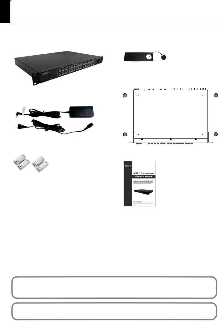
The following items are included. Please make sure that all items are present. If anything is missing, please contact your dealer.
MVS-12 itself |
Rubber Foot (four) |
Attach the included rubber feet as needed. Refer the figure below to attach.
* The rubber feet are arraged onto one pad. Remove from the pad to use them.
AC Adaptor and Power Cord
Ferrite Core (two)
Owner’s Manual (this document)
The explanations in this manual include illustrations that depict what should typically be shown by the display. Note, however, that your unit may incorporate a newer, enhanced version of the system, so what you actually see in the display may not always match what appears in the manual.
MMP (Moore Microprocessor Portfolio) refers to a patent portfolio concerned with microprocessor architecture, which was developed by Technology Properties Limited (TPL). Roland has licensed this technology from the TPL Group.
3

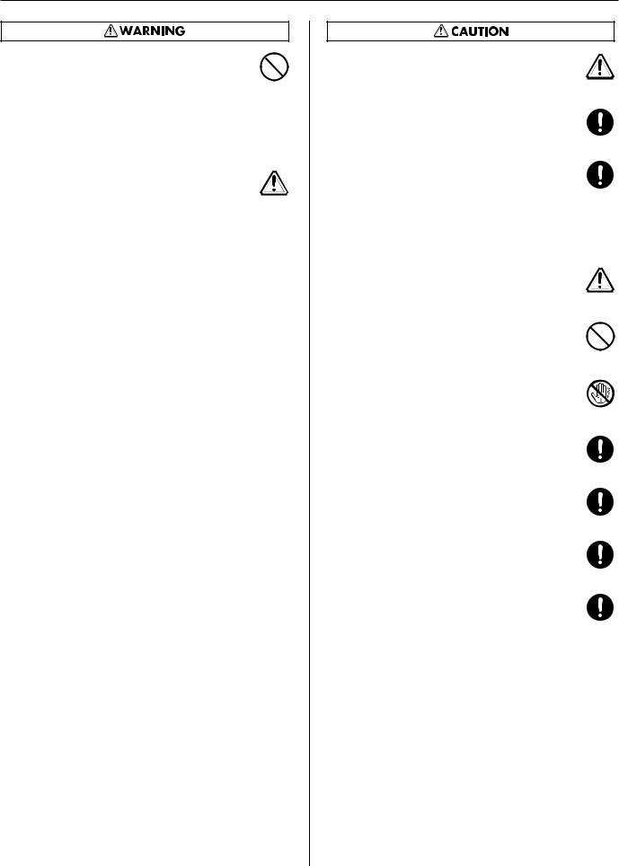
USING THE UNIT SAFELY
Used for instructions intended to alert the user to the risk of death or severe injury should the unit be used improperly.
Used for instructions intended to alert the user to the risk of injury or material damage should the unit be used improperly.
* Material damage refers to damage or other adverse effects caused with respect to the home and all its furnishings, as well to domestic animals or pets.
The symbol alerts the user to important instructions or warnings.The specific meaning of the symbol is determined by the design contained within the triangle. In the case of the symbol at left, it is used for
The  symbol alerts the user to items that must never be carried out (are forbidden). The specific thing that must not be done is indicated by the design contained within the circle. In the case of the symbol at left, it means that the unit must never be disassembled.
The ● symbol alerts the user to things that must be carried out. The specific thing that must be done is indicated by the design contained within the circle. In the case of the symbol at left, it means that the powercord plug must be unplugged from the outlet.
•Do not open (or modify in any way) the unit or its AC adaptor.
.................................................................................................................................
•Do not attempt to repair the unit, or replace parts within it (except when this manual provides specific instructions directing you to do so). Refer all servicing to your retailer, the nearest Roland Service Center, or an authorized Roland distributor, as listed on the “Information” sheet.
.................................................................................................................................
•Never install the unit in any of the following locations.
• Subject to temperature extremes (e.g., direct sunlight in an enclosed vehicle, near a heating duct, on top of heatgenerating equipment); or are
• Damp (e.g., baths, washrooms, on wet floors); or are
•Exposed to steam or smoke; or are
•Subject to salt exposure; or are
•Humid; or are
•Exposed to rain; or are
•Dusty or sandy; or are
•Subject to high levels of vibration and shakiness.
.................................................................................................................................
•Make sure you always have the unit placed so it is level and sure to remain stable. Never place it on stands that could wobble, or on inclined surfaces.
.................................................................................................................................
•Be sure to use only the AC adaptor supplied with the unit. Also, make sure the line voltage at the installation matches the input voltage specified on the AC adaptor’s body. Other AC adaptors may use a different polarity, or be designed for a different voltage, so their use could result in damage, malfunction, or electric shock.
.................................................................................................................................
•Use only the attached power-supply cord. Also, the supplied power cord must not be used with any other device
.................................................................................................................................
4
•Do not excessively twist or bend the power cord, nor place heavy objects on it. Doing so can damage the cord, producing severed elements and short circuits. Damaged cords are fire and shock hazards!
.................................................................................................................................
•Do not place containers containing liquid (e.g., flower vases) on this product. Never allow foreign objects (e.g., flammable objects, coins, wires) or liquids (e.g., water or juice) to enter
into this product. Doing so may cause short circuits, faulty operation, or other malfunctions.
.................................................................................................................................
•Immediately turn the power off, remove the AC adaptor from the outlet, and request servicing by your retailer, the nearest Roland Service Center, or an authorized Roland distributor, as listed on the “Information” sheet when:
•The AC adaptor, the power-supply cord, or the plug has been damaged; or
•If smoke or unusual odor occurs
•Objects have fallen into, or liquid has been spilled onto the unit; or
•The unit has been exposed to rain (or otherwise has become wet); or
•The unit does not appear to operate normally or exhibits a marked change in performance.
.................................................................................................................................
•In households with small children, an adult should provide supervision until the child is capable of following all the rules essential for the safe operation of the unit.
.................................................................................................................................
•Protect the unit from strong impact. (Do not drop it!)
.................................................................................................................................
USING THE UNIT SAFELY
•Do not force the unit’s power-supply cord to share an outlet with an unreasonable number of other devices. Be especially careful when using extension cords—the total power used by all devices you have connected to the extension cord’s outlet must never exceed the power rating (watts/amperes) for the extension cord. Excessive loads can cause the insulation on the cord to heat up and eventually melt through.
.................................................................................................................................
•Before using the unit in a foreign country, consult with your retailer, the nearest Roland Service Center, or an authorized Roland distributor, as listed on the “Information” sheet.
.................................................................................................................................
•The unit and the AC adaptor should be located so their location or position does not interfere with their proper ventilation.
.................................................................................................................................
•Always grasp only the plug on the AC adaptor cord when plugging into, or unplugging from, an outlet or this unit.
.................................................................................................................................
•At regular intervals, you should unplug the AC adaptor and clean it by using a dry cloth to wipe all dust and other accumulations away from its prongs. Also, disconnect the power plug from the power outlet whenever the unit is to remain unused for an extended period of time. Any accumulation of dust between the power plug and the power outlet can result in poor insulation and lead to fire.
.................................................................................................................................
•Try to prevent cords and cables from becoming entangled. Also, all cords and cables should be placed so they are out of the reach of children.
.................................................................................................................................
•Never climb on top of, nor place heavy objects on the unit.
.................................................................................................................................
•Never handle the AC adaptor or its plugs with wet hands
when plugging into, or unplugging from, an outlet or this unit.
.................................................................................................................................
•Before moving the unit, disconnect the AC adaptor and all cords coming from external devices.
.................................................................................................................................
•Before cleaning the unit, turn off the power and unplug the AC adaptor from the outlet (p. **).
.................................................................................................................................
•Whenever you suspect the possibility of lightning in your area, disconnect the AC adaptor from the outlet.
.................................................................................................................................
•Keep screws of earth terminal or rack mount angles you may remove and included ferrite cores or rubber feet in a safe place out of children's reach, so there is no chance of them being swallowed accidentally.
................................................................................................................................................
5

IMPORTANT NOTES
Power Supply
•Do not connect this unit to same electrical outlet that is being used by an electrical appliance that is controlled by an inverter (such as a refrigerator, washing machine, microwave oven, or air conditioner), or that contains a motor. Depending on the way in which the electrical appliance is used, power supply noise may cause this unit to malfunction or may produce audible noise. If it is not practical to use a separate electrical outlet, connect a power supply noise filter between this unit and the electrical outlet.
•The AC adaptor will begin to generate heat after long hours of consecutive use. This is normal, and is not a cause for concern.
•Before connecting this unit to other devices, turn off the power to all units. This will help prevent malfunctions and/or damage to monitors or other devices.
Placement
•This device may interfere with radio and television reception. Do not use this device in the vicinity of such receivers.
•When moved from one location to another where the temperature and/or humidity is very different, water droplets (condensation) may form inside the unit. Damage or malfunction may result if you attempt to use the unit in this condition. Therefore, before using the unit, you must allow it to stand for several hours, until the condensation has completely evaporated.
•Depending on the material and temperature of the surface on which you place the unit, its rubber feet may discolor or mar the surface. You can place a piece of felt or cloth under the rubber feet to prevent this from happening. If you do so, please make sure that the unit will not slip or move accidentally.
Maintenance
•For everyday cleaning wipe the unit with a soft, dry cloth or one that has been slightly dampened with water. To remove stubborn dirt, use a cloth impregnated with a mild, non-abrasive detergent. Afterwards, be sure to wipe the unit thoroughly with a soft, dry cloth.
•Never use benzine, thinners, alcohol or solvents of any kind, to avoid the possibility of discoloration and/or deformation.
6
Additional Precautions
•Use a reasonable amount of care when using the unit’s buttons, sliders, or other controls; and when using its jacks and connectors. Rough handling can lead to malfunctions.
•When connecting / disconnecting all cables, grasp the connector itself—never pull on the cable. This way you will avoid causing shorts, or damage to the cable’s internal elements.
•When you need to transport the unit, package it in the box (including padding) that it came in, if possible. Otherwise, you will need to use equivalent packaging materials.

Contents |
|
About Power Supply....................................................................................... |
8 |
Connecting the AC adaptor................................................................................................................................................... |
8 |
Turning the Power On/Off...................................................................................................................................................... |
9 |
Names of Things and What They Do .......................................................... |
10 |
Front Panel................................................................................................................................................................................. |
10 |
Rear Panel................................................................................................................................................................................... |
11 |
Connecting External Equipment ................................................................ |
12 |
Connecting a Video Camera, Player, or Other Sources (Use as a Matrix Switcher).......................................... |
12 |
Connecting a Video Mixer (Use as a Multi-Viewer) ..................................................................................................... |
13 |
Connecting Output Devices ................................................................................................................................................ |
14 |
Connecting Monitors................................................................................................................................................ |
14 |
Connecting Projectors or Recorders ................................................................................................................... |
15 |
Connecting a Mouse .............................................................................................................................................................. |
15 |
Use As a Multi-Viewer.................................................................................. |
16 |
Switching the Display Mode................................................................................................................................................ |
16 |
Switching Using Buttons......................................................................................................................................... |
17 |
Switching Using the Mouse ................................................................................................................................... |
17 |
Changing the Display Location for Channels .................................................................................................. |
18 |
Changing the Aspect Ratios of the Channels .................................................................................................. |
19 |
Saving Settings to MEMORY Buttons ............................................................................................................................... |
20 |
Synchronizing with Operation of the LVS-800 ............................................................................................................. |
21 |
Use As a Matrix Switcher ............................................................................. |
22 |
Using Buttons to Select the Output Destination and Source.................................................................................. |
22 |
Using the Mouse to Select the Output Destination and Source ............................................................................ |
23 |
Saving Settings to MEMORY Buttons ............................................................................................................................... |
24 |
Synchronizing with Operation of the V-1600HD ......................................................................................................... |
25 |
Menu Operations and Menu List ................................................................ |
26 |
Menu Operations..................................................................................................................................................................... |
26 |
Menu List .................................................................................................................................................................................... |
27 |
Other Features ............................................................................................. |
29 |
Switching Between NTSC and PAL.................................................................................................................................... |
29 |
Switching the Output Format............................................................................................................................................. |
30 |
Changing the Names of Channels..................................................................................................................................... |
31 |
Copying/Resetting Values in Memory ............................................................................................................................. |
33 |
Limiting the Number of Inputs ........................................................................................................................................... |
35 |
Locking Panel Operations .................................................................................................................................................... |
36 |
Returning to the Factory-default State (Factory Reset) ............................................................................................. |
36 |
Remote Control ........................................................................................................................................................................ |
36 |
Appendices................................................................................................... |
37 |
Main Specification................................................................................................................................................................... |
37 |
About Rack Mounting............................................................................................................................................................ |
37 |
Dimensions ................................................................................................................................................................................ |
37 |
Troubleshooting ...................................................................................................................................................................... |
38 |
7
About Power Supply
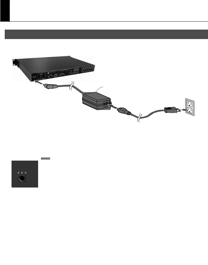
Connecting the AC adaptor
Connect the AC adaptor to MVS-12. Place the AC adaptor so the side with the indicator (see illustration) faces upwards and the side with textual information downwards. The indicator will light when you plug the AC adaptor into an AC outlet.
Indicator
About Cord Hook
To prevent the inadvertent disruption of power to your unit (should the plug be pulled out accidentally), and to avoid applying undue stress to the AC adaptor jack, anchor the power cord using the cord hook, as shown in the illustration.
* When you anchor the power cord, avoid the cord to be rubbed with rear panel and be dammaged.
Caution regarding the power supply
Depending on the circumstances of a particular setup, you may experience a discomforting sensation, or perceive that the surface feels gritty to the touch when you touch this device, cameras connected to it, or the metal portions of other objects, such as VCRs. This is due to an infinitesimal electrical charge, which is absolutely harmless. However, if you are concerned about this, connect the ground terminal (see figure) with an external ground. When the unit is grounded, a slight noise may occur, depending on the particulars of your installation. If you are unsure of the connection method, contact the nearest Roland Service Center, or an authorized Roland distributor, as listed on the “Information” sheet.
Unsuitable places for connection
•Water pipes (may result in shock or electrocution)
•Gas pipes (may result in fire or explosion)
•Telephone-line ground or lightning rod (may be dangerous in the event of lightning)
8
About Power Supply
Turning the Power On/Off
*Once the connections have been completed (p. 8), turn on power to your various devices in the order specified. By turning on devices in the wrong order, you risk causing malfunction and/or damage to video monitors and other devices.
*This unit is equipped with a protection circuit. A brief interval (a few seconds) after power up is required before the unit will operate normally.
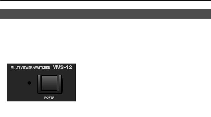
Turning the Power On
Make sure the power cable is securely inserted, then press the [POWER] button located on the front panel. It takes several seconds for the system to start. When the power comes on, the indicator lights up green.
Turning the Power Off
Press the [POWER] button located on the front panel. The color of the indicator changes from green to red.
9
Names of Things and What They Do
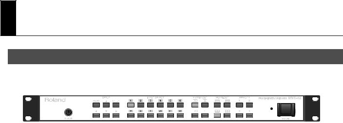
Front Panel
1 |
2 |
3 |
4 |
5 |
6 |
7 |
|
||||
|
|
|
|
|
|
|
|
|
|
|
|
|
|
|
|
|
|
|
|
|
|
|
|
|
|
|
|
|
|
|
|
|
|
|
|
|
|
|
|
|
|
|
|
|
|
|
|
|
|
|
|
|
|
|
|
|
|
|
|
|
|
|
|
|
|
|
|
|
|
|
|
|
|
|
|
|
|
|
|
|
|
|
|
1. MOUSE Connector (p. 15)
This allows connection of a commercially available PS/2 mouse. This enables you to use a mouse to perform operations instead of using the buttons on the front panel.
2. SETUP Buttons (p. 26)
These are used for displaying various menu items and making system settings.
3. INPUT SELECT Buttons (p. 18, p. 22)
You can use these for the two purposes described below.
• When using the unit as a multi-viewer
This lets you specify the display locations of the respective sources.
•When using the unit as a matrix switcher
Using these in combination with the MATRIX OUT buttons lets you select the output channel for each source.
4. MATRIX OUT Buttons (p. 22)
When you’re using the unit as a matrix switcher, you can use these to choose the destination channels for output.
5. MULTI-OUT Buttons (p. 17)
When you’re using the unit as a multi-viewer, you can use these to switch the display mode.
6. MEMORY Buttons (p. 20, p. 24)
You can use these to save the display mode and the settings for input and output. You can then call up saved settings in a single step.
7. POWER Button/Indicator (p. 9)
This switches the MVS-12 on and off. The indicator lights up green when the power comes on. When the power is switched off, the indicator lights up red.
10
Names of Things and What They Do
Rear Panel
1 |
|
|
|
2 |
|
|
|
3 |
4 |
5 |
6 |
|
|
|
|
7 |
|
|
|
|||||||||||||||
|
|
|
|
|
|
|
|
|
|
|
|
|
|
|
|
|
|
|
|
|
|
|
|
|
|
|
|
|
|
|
|
|
|
|
|
|
|
|
|
|
|
|
|
|
|
|
|
|
|
|
|
|
|
|
|
|
|
|
|
|
|
|
|
|
|
|
|
|
|
|
|
|
|
|
|
|
|
|
|
|
|
|
|
|
|
|
|
|
|
|
|
|
|
|
|
|
|
|
|
|
|
|
|
|
|
|
|
|
|
|
|
|
|
|
|
|
|
|
|
|
|
|
|
|
|
|
|
|
|
|
|
|
|
|
|
|
|
|
|
|
|
|
|
|
|
|
|
|
|
|
|
|
|
|
|
|
|
|
|
|
|
|
|
|
|
|
|
|
|
|
|
|
|
|
|
|
|
|
|
|
|
|
|
|
|
|
|
|
|
|
|
|
|
|
|
|
|
|
|
|
|
|
|
|
|
|
|
|
|
|
|
|
|
|
|
|
|
|
|
|
|
|
|
|
|
|
|
|
|
|
|
|
|
|
|
|
|
|
|
|
|
|
|
|
|
|
|
|
|
|
|
|
|
|
|
|
|
|
|
|
|
|
|
|
|
|
|
|
|
|
|
|
|
|
|
|
|
|
|
|
|
|
|
|
|
|
|
|
|
|
|
|
|
|
|
|
|
|
|
|
|
|
|
|
|
|
|
|
|
|
|
|
|
|
1. AC Adapter Connector
This is for connecting the included AC adapter.
2. MIDI IN and OUT/THRU Connectors
You can use these when using a MIDI device to operate the unit remotely, or when using the unit to send MIDI data to an external device.
3. RS-232C Connector
You can use this when using an external RS-232C serial device to operate the unit remotely.
4. LAN Connector
You can use this when using a connected computer to operate the unit remotely, or when setting the multi-viewer screen functions on a computer screen.
For more information about remote control, download the separately available reference document from the following Roland website.
http://www.rolandsystemsgroup.net/
5. MULTI-OUT (MENU) Connectors
Here you connect monitors for viewing video sources or outputs. The same video is output from the two connectors shown below. For information on output format, refer to “Main Specifications” (p. 37).
• RGB Connector
This is a D-Sub 15-pin connector. Here you connect a computer monitor or other such display.
• HDMI Connector
Here you connect a TV or computer monitor that is equipped with HDMI or DVI-D input.
*The menu items for the MVS-12 are also displayed on these monitors. Going to SETUP and pressing the [MENU] button displays the menu items.
6.MATRIX OUT Connectors
When you’re using the unit as a matrix switcher, you can use these to connect projectors, recorders, or other devices for output. Connectors 1 through 4 correspond to [MATRIX OUT] buttons 1 through 4 on the front panel.
You can also connect a preview video monitor to the PREVIEW connector.
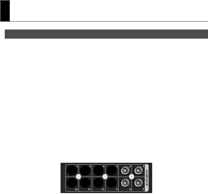
7. VIDEO INPUT Connectors
• When using the unit as a multi-viewer
Connect these to Monitor Output, Input Loop-Thru, or Program/Preview Output on a video mixer.
• When using the unit as a matrix switcher
Connect video cameras, video players, or other sources.
11
Connecting External Equipment
Connecting a Video Camera, Player, or Other Sources (Use as a Matrix Switcher)
Connect source devices such as video cameras, players or the outputs from a video mixer to the VIDEO INPUT connectors on the MVS-12. When you’re using the unit as a matrix switcher, make the connections as shown here.
* To prevent malfunction or damage to video cameras or other devices, always turn off the power on all devices before making any connections.
12
 Loading...