

Gap
b
b
b
■
❑
❑
A
B
C
D
E
F
G
H
I
a
b
c
d
e
f
1.
2.
3.
4.
5.
6.
7.
Leaflet For a Dealer or a Qualified Professional Installer (LX-10)
•
This leaflet is for a dealer or a qualified professional installer. The customer should not attempt to assemble the instrument.
• Make sure that another person is on hand to help with the assembly and setup.
• Do not use a power tool (e.g., an electric screwdriver) to assemble the stand. You risk damaging or stripping the screws.
• Since this product is very heavy, you must make sure that a sufficient number of people are on hand to help, so you can lift and move it safely,
without causing strain.
• Should you remove the screws, and cord clamps, keep them in a safe place out of children’s reach, so there is no chance of them being swallowed
accidentally.
• Please consult your Roland dealer to assemble the piano. Roland cannot warrant the safety of the assemble operation, if this operation is carried
out by the customer.
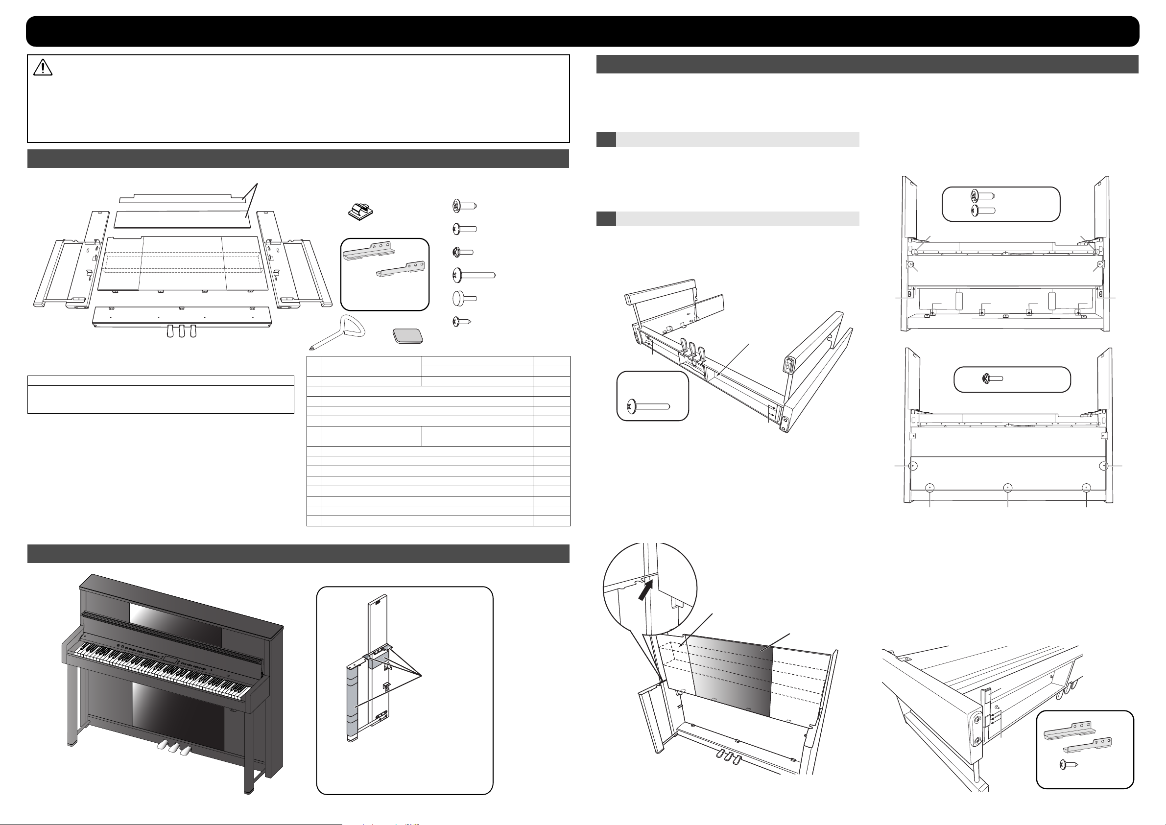
Checking the Included Items
(E)
(D)
(A)
(C)
(B)
Items required for assembly
Phillips screwdriver
Thick blanket
This is used to protect the piano, and to avoid scratching
the walls or floor of the location where the assembly is performed. Be sure to use a blanket of sufficient size.
Assembly Procedure
Before you begin assembling the stand, check that all the parts were supplied.
These parts are attached
from the rear side.
(F)
(a)
(A)
(H)
(G)
Right
Left
Attach these to the
stand in step 6 of
“Assembling the stand.”
(I)
Side board
Pedal board
Front board (with speaker box)
Rear board
Rear board Upper
Cord clamps
Stabilizer
Screwdriver
Felt
Screws (M6 x 20 mm)
Screw (M5 x 20 mm)
Screws (M4 x 16 mm)
Screws (M5 x 40 mm)
Thumbscrew
Screws (4 x 16 mm)
(b)
(c)
(d)
(e)
(f)
L 1
R 1
L 1
R 1
Assembly Procedure
* First, assemble the unit provisionally, using your fingers to lightly tighten
the screws. Next, use a screwdriver to securely tighten the screws, then
place the unit on a flat and stable surface.
* Do not allow the pedal cord or power cord to get twisted or pinched
while assembling the unit.
1 Check Before Assembling
• The surfaces of the piano unit and of the stand are easily scratched;
handle with care to avoid scratching them.
• Do not place the main piano unit directly on the floor. Doing so will
damage the External memory holder located on the bottom panel, or
the Bottom Panel case.
2 Assembling the Stand
* Lay down a thick blanket on your work surface to prevent the stand or
the floor from being scratched.
Fasten the side boards L/R (A) to the pedalboard (B) as shown in the
illustration, using two screws (d) each at the left and right sides.
(A)
Fasten the top part of the front board (C) to the left and right side boards
(A) using one screw (a) each at the left and right sides.
Next, fasten the rear and bottom of the speaker box to the side panel
using two screws (b) each at the left and right sides.
Finally, fasten the bottom of the front board (C) to the pedalboard (B)
using screws (b) at four locations.
* Tighten the screws in the order shown above. Distortion may occur if
you fail to observe the correct order.
* If your screwdriver will not go in when tightening the screws of the
pedalboard, use the included screwdriver (H).
M6 x 20 mm
M5 x 20 mm
(C)
(b)
(b)
(a)
(b)
(b)
(b)
(b)
(a)
(b)
(a)
(b)
(b)
Route the pedal
cord outside.
(d)
1
1
1
1
3
(d)
M5 x 40 mm
(B)
(A)
Fasten the rear board (D) using screws (c) at five locations.
(c)
M4 x 16 mm
(d)
1
2
4
10
5
4
3
6
Taking care that the pedalboard (B) is not twisted, raise the assembly
upright.
From above, pass the front board (C) through the gap in the side panel
hardware, and insert it so that it is in complete contact with the holder
on the rear side.
* This step must be carried out by at least two people.
* Be careful not to scratch the front boards.
* Do not grasp the mirror surface of the front board. Doing so may
scratch the mirror surface.
Gap
The speaker box is attached to the rear.
Mirror surface
(c)
(c)
Attach the stabilizers.
Stabilizer hardware to prevent tipping is included with the LX-10.
There is no danger of tipping with normal use. However, if you will not
be placing the piano against a wall, you should attach the stabilizers
for maximum safety.
Please be aware that even if the stabilizers are attached, tipping may
still be possible under certain circumstances of handling. Please use
caution.
Lay the stand forward as shown in the illustration, and attach the
stabilizers (G) to the bottom of the stand using screws (f) at three
locations each for the left and right sides.
* Take care not to attach the left and right stabilizer to the wrong sides.
(D)
(c) (c)
(c)
Packing sheets
(G)
(C)
The packing sheets that protect the side boards
*
should not be removed until you have finished
the step “2. Assembling the stand.”
This will prevent the side boards from being
scratched during assembly.
Remove the packing sheet from the left and right side boards.
(f)
(G)
(f)
4 x 16 mm
Right
Left

e
e
e
1.
2.
3.
4.
5.
1.
2.
3.
1.
2.
1.
1.
2.
3.
4.
3 Attaching the Piano Main Unit to the Stand
* This step must be carried out by at least two people.
With another person helping you, lift the instrument at its left and right
ends and place it on the holder hardware at the top of the front legs of
the stand, as shown in the illustration.
Adjust the position so that the instrument fits between the left and right
side boards.
* Be careful not to scratch the left and right side boards.
* Do not grasp the top lid of the piano.
* The gap between the top edge of the stand and the instrument is
narrow; be careful not to pinch your hand.
Make sure that there is no gap between the instrument and the stand.
Gap
Open the top lid, and fasten screws (a) from the inside at one location
each for the left and right sides.
* Hold the top lid firmly so that your hand is not pinched while you’re
tightening the screws.
* Do not force the lid backward. Doing so may cause breakage.
* If there is a gap as shown in the figure for step 3, press the main piano
unit against the stand while you tighten the screws.
Top lid
(a)
M6 x 20 mm
(a)
Connecting the Pedal Cord, the Power Cord
4
and Speaker Cable
Connect the speaker cable to the connector located in the center of the
lower part of the rear panel.
Push the cable in until you hear it click into position.
Plug the pedal cord into the Pedal connector in theBottom Panel (Rear)
on the LX-10’s bottom left panel.
Connect the supplied power cord to the AC In (AC inlet) located in the
Bottom Panel (Rear).
2
1
Attaching the Rear Board Upper
5
Fasten the rear board upper (E) using Thumbscrew (e) at three locations.
At this time, route the pedal cord and power cord through the cutout
located at the right side as seen from the rear.
Secure the pedal cord and power cord in place with the cord clamps (F),
after affixing them at locations (1), (2), and (3) (recommended) as
shown in the figure below.
6 Adjusting the Adjuster
Turn the adjuster of the pedalboard (B) to lower it until the adjuster is
firmly in contact with the floor.
* If there is a gap between the pedals and the floor, the pedals may be
damaged.
* In particular when placing the instrument on carpet, adjust this so that
the pedals firmly contact the floor.
3
Adjuster
This completes the assembly procedure.
Verify that no screws or other parts are left over.
About the Included Felt
If the unit is placed on a wood floor or similar surface, it may not be perfectly
stable due to irregularities in the floor. If so, place the included felt (I) under
the front legs
Slide the instrument straight toward the rear as shown in the illustration,
attaching it to the stand.
As shown in the illustration, use screws (b) to fasten the holder
hardware on top of the left and right front legs to the instrument at one
location each for the left and right sides.
(b)
(b)
M5 x 20 mm
(F)
(e)
(e)
(E)
(e)
(D)
Cord clamps
Thumbscrew
(e)
(1)
(2)
(3)
Felt (I)
When Transporting the Unit
Close the Top lid and the lid.
Unplug the power cord from the AC outlet.
Raise the pedal’s adjuster.
Grasping the left and right cutouts of the rear panel’s rear board upper,
and the left and right bottom of the keyboard, and while keeping it
level, lift the instrument and transport it, taking care not to pinch your
hands or drop the instrument on your feet.
Give this leaflet to the customer so that it can be kept
together with the owner’s manual.
Copyright © 2008 ROLAND CORPORATION
All rights reserved. No part of this publication may be reproduced in any
form without the written permission of ROLAND CORPORATION.
*5100003600 - 05*
 Loading...