

Page 1

Oct. 2016 KTN-50
SERVICE NOTES
Issued by RJA
KATANA-50
Table of Contents
Cautionary Notes ..............................................................2
Specifications .....................................................................3
Location of Controls (Top)...............................................4
Location of Controls Parts List (Top) .............................4
Location of Controls (Rear)..............................................5
Location of Controls Parts List (Rear)............................5
Exploded View (Cabinet).................................................6
Exploded View Parts List (Cabinet) ...............................7
Disassembly Procedure....................................................7
Plain View (Cabinet: 1).....................................................8
Plain View (Cabinet: 2).....................................................9
Exploded View (Chassis) ...............................................10
Exploded View Parts List (Chassis)..............................11
Plain View (Chassis: 1) ...................................................12
Plain View (Chassis: 2) ...................................................13
Wiring Diagram/Block Diagram..................................14
Parts List ...........................................................................16
Verifying the Version......................................................19
Data Backup and Restore Operations ..........................19
System Update Procedure..............................................19
Performing a Factory Reset............................................19
Test Mode.........................................................................20
Circuit Board (Main Board) ...........................................24
Circuit Diagram (Main Board: 1/3)..............................26
Circuit Diagram (Main Board: 2/3)..............................28
Circuit Diagram (Main Board: 3/3)..............................30
Circuit Board (Panel, Amp, Jack, Input, Fuse Board) 32
Circuit Diagram (Panel Board)......................................34
Circuit Diagram (Amp Board).......................................36
Circuit Diagram (Jack Board) ........................................37
Circuit Diagram (Input Board)......................................38
Circuit Diagram (Fuse Board) .......................................38
Copyright © 2016 Roland Corporation
All rights reserved. No part of this publication may be reproduced in any form without the written permission
of Roland Corporation.
CC-KWS17057053E0
Page 2

Oct. 2016 KTN-50
Cautionary Notes
Before beginning the procedure, please read
through this document. The matters described may
differ according to the model.
Back Up User Data!
User data may be lost during the course of the procedure. Refer to Data
Backup and Restore Operations (p. 19) in the Service Notes and save the
data. After completing the procedure, restore the backed-up data to the
product.
Part Replacement
When replacing components near the power-supply circuit or a heatgenerating circuit (such as a circuit provided with a heat sink or including a
cement resistor), carry out the procedure according to the instructions with
respect to the part number, direction, and attachment position (mounting so as
to leave an air gap between the component and the circuit board, etc.).
Parts List
A component whose part code is ******** will not be supplied as a service part
because one of the following reasons applies.
• Because it is supplied as an assembled part (under a different part code).
• Because a number of circuit boards are grouped together and supplied as
a single circuit board (under a different part code).
• Because supply is prohibited due to copyright restrictions.
• Because reissuance is restricted.
• Because the part is made to order (at current market price).
• Because it is carried in electronic data on the Roland web site.
• Because it is a package or an accessory irrelevant to the function
maintenance of the main body.
• Because it can be replaced with an article on the market. (battery or etc.)
Circuit Diagram
In the circuit diagram, “NIU” is an abbreviation for “Not in Use,” and
“UnPop” is an abbreviation for “Unpopulated.” They both mean non-mounted
components. The circuit board and circuit board diagram show silk-screened
indications, but no components are mounted.
Roland Japan Warranty
Please send the problem report with followings when the defect occurred
within one year from production and within one month from the first
customer’s purchase.
• Model name:
• Serial number:
•Version:
• Purchase date by the first customer: yyyy/mm/dd
•Symptom:
• Frequency: always, sometimes or seldom
• Confirmed the symptom at your service dept: Yes/No
Please send the problem report to rjasc@roland.co.jp.
2
Page 3

Oct. 2016 KTN-50
Specifications
BOSS KATANA-50: Guitar Amplifier
Rated Power Output
50 W
Nominal Input Level
INPUT: -10 dBu (1 MΩ)
AUX IN: -10 dBu
Speaker
30 cm (12 inches) x 1
Controls
POWER switch
MASTER knob
POWER CONTROL switch (STANDBY, 0.5 W, 25 W, 50 W)
[AMPLIFIER]
AMP TYPE switch (ACOUSTIC, CLEAN, CRUNCH, LEAD, BROWN)
GAIN knob
VOLUME knob
[EQUALIZER]
BASS knob
MIDDLE knob
TREBLE knob
[MULTI EFFECT]
BOOSTER/MOD button
DELAY/FX button
REVERB button
TAP button
BOOSTER/MOD knob
DELAY/FX knob
REVERB knob
[TONE SETTING]
CH1 button
CH2 button
PANEL button
Power Consumption
47 W
Dimensions
470 (W) x 238 (D) x 398 (H) mm
18-9/16 (W) x 9-3/8 (D) x 15-11/16 (H) inches
Weight
11.6 kg
25 lbs 10 oz
Accessories
Owner’s Manual (#5100052281)
Power cord (#5100029165, #5100012292, #00894378, #03450323, #5100013648,
#00907001, #00894389, #5100013842)
Options (sold separately)
Footswitch: BOSS FS-5L
Expression pedal: Roland EV-5, BOSS FV-500L, BOSS FV-500H
* 0 dBu = 0.775 Vrms
* Printed matters will not be supplied after the end of the production. Then,
download the electronic file from the Roland web site.
* In the interest of product improvement, the specifications and/or appearance of
this unit are subject to change without prior notice.
Indicators
BOOSTER/MOD
DELAY/FX
REVERB
TAP
CH1
CH2
PANEL
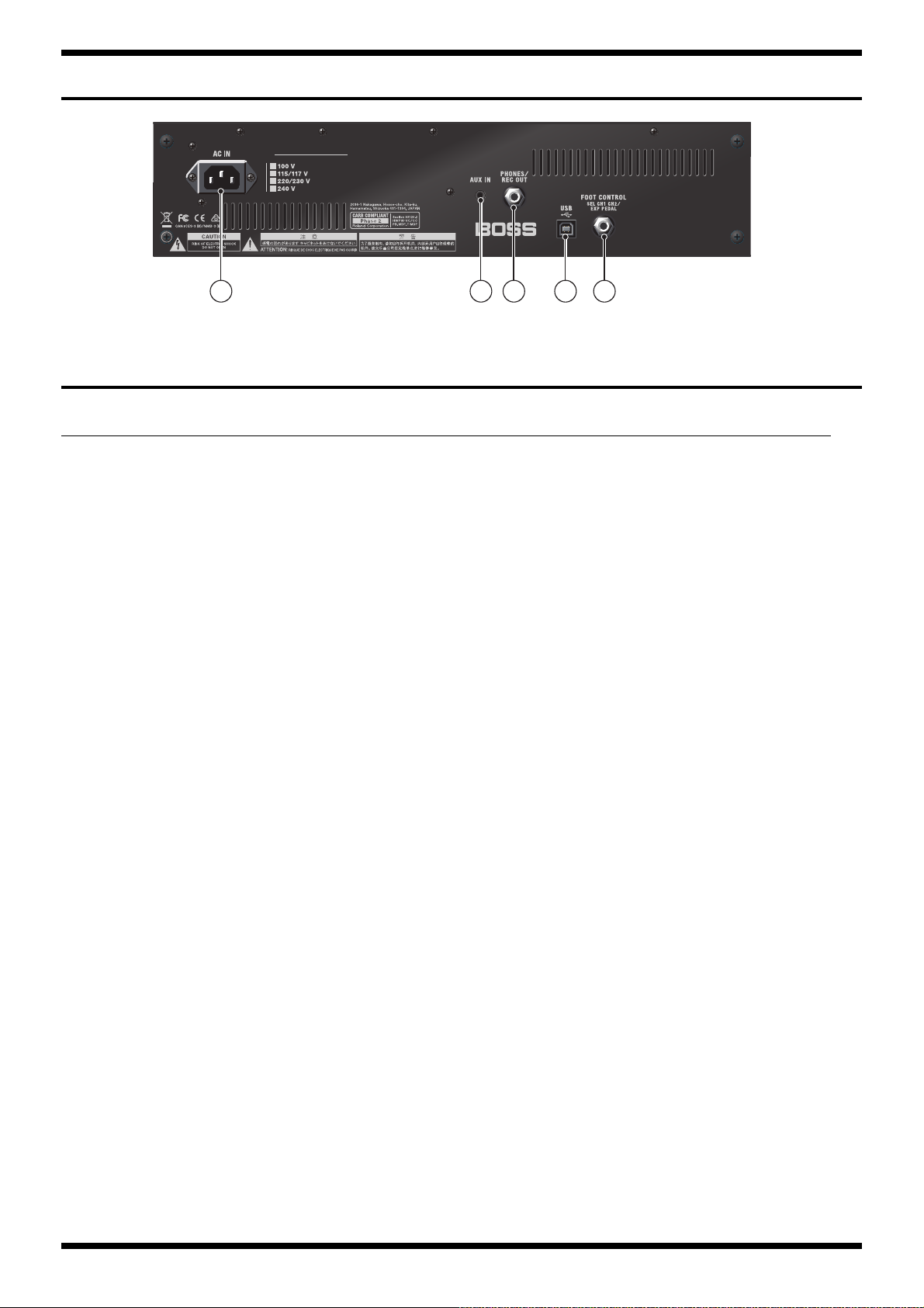
Connectors
INPUT jack: 1/4-inch phone type
AUX IN jack: Stereo miniature phone type
REC OUT/PHONES jack: Stereo 1/4-inch phone type
EXP PEDAL/CTL CH1/CH2 jack: 1/4-inch TRS phone type
USB port: USB B type
AC IN jack
3
Page 4

Oct. 2016 KTN-50
Location of Controls (Top)
fig.panel-top.eps
5
1 2
3 87 94 6
Location of Controls Parts List (Top)
No. Part Code Part Name Description Q’ty
1 5100052218 S-KEYTOP 3
01780101 TACT SWITCH SKQKABD010 3
05011067 LED L-3WEGW (153-L-3WEGW) 3
2 5100052218 S-KEYTOP 3
01780101 TACT SWITCH SKQKABD010 3
5100003359 LED(RED) L-34ID (153-L-34IDSLLF) 3
5100051747 LED SPACER LH-5-1.5 3
3 5100031944 6.5MM JACK PJ-644C-EP 1
5100046593 JACK SPACER 1
******** JACK NUT attached to JACK 1
******** JACK WASHER attached to JACK 1
4 5100052214 R-KNOB INDEX 1
5100052460 ROTARY POTENTIOMETER RD901F-40-15F-B10K-05D60A 1
******** VR NUT (M9) attached to VR 1
5 5100052214 R-KNOB INDEX 8
5100052467 ROTARY POTENTIOMETER RD901F-40E1-15F-0B10K-00D86A 8
******** VR NUT (M9) attached to VR 8
6 5100052217 C-KEYTOP 1
01780101 TACT SWITCH SKQKABD010 1
5100003359 LED(RED) L-34ID (153-L-34IDSLLF) 1
5100051747 LED SPACER LH-5-1.5 1
7 5100052214 R-KNOB INDEX 1
5100022034 ROTARY POT(231-11017-03-00) RD901F-40E1-15F-1B20K-00DN6 1
******** VR NUT (M9) attached to VR 1
8 5100049813 INDEX KNOB 1
5100052466 ROTARY POTENTIOMETER RD901F-40-125F-B10K-04D60A 1
******** VR NUT (M7) attached to VR 1
9 02897801 SEESAW SWITCH SDDJE13200 94V-0 1
5100046595 POWER SW ESCUTCHEON 1
5100046598 POWER SW CUSHION 2
4
Page 5
Oct. 2016 KTN-50
1 2 3 4 5
Location of Controls (Rear)
fig.panel-rear.eps
Location of Controls Parts List (Rear)
No. Part Code Part Name Description Q’ty
1 5100051443 AC INLET M1909-C 1
2 5100050453 3.5MM JACK HSJ2000-01-010 1
3 5100024419 6.5MM JACK PJ-644C-04-EP(610-11020-01-00 1
5100046593 JACK SPACER 1
******** JACK NUT attached to JACK 1
******** JACK WASHER attached to JACK attached to JACK 1
4 5100009531 USB CONNECTOR B TYPE FEMALE YKF45-0044N 1
5 5100031944 6.5MM JACK PJ-644C-EP 1
5100046593 JACK SPACER 1
******** JACK NUT attached to JACK 1
******** JACK WASHER attached to JACK attached to JACK 1
5
Page 6
Oct. 2016 KTN-50
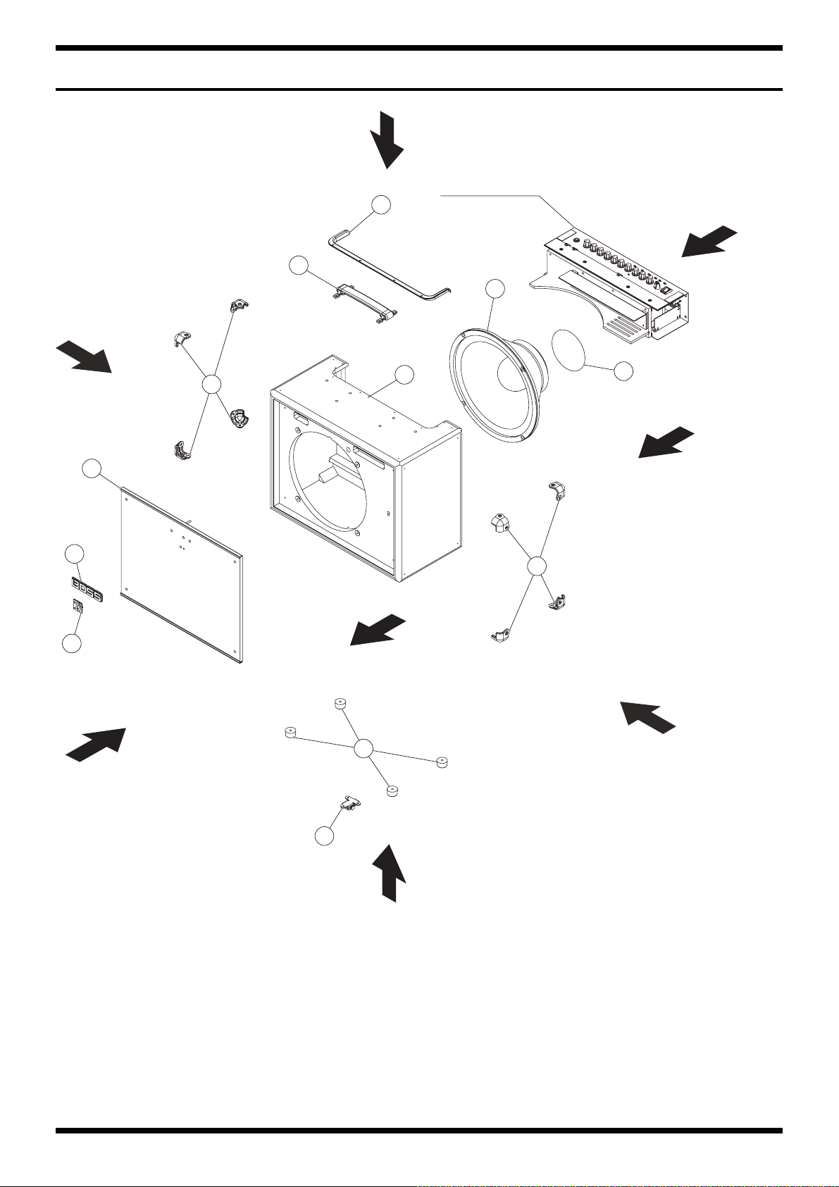
Exploded View (Cabinet)
fig.bunkai-cabinet.eps
View 3
Refer to Chassis
1
View 1
2
3
View 6
7
8
5
View 7
6
4
6
View 8
9
11
View 2
View 5
6
10
View 4
Page 7

Oct. 2016 KTN-50
Exploded View Parts List (Cabinet)
No. Part Code Part Name Description Q’ty
1 5100052235 TRIM SASH 1
2 5100049817 HANDLE 1
3 5100052293 SPEAKER W1204-067A 1
5100053344 CABINET ASSY W/O SPEAKER 1
4 ******** CABINET 1
5 ******** NET BOARD 1
6 5100052238 CORNER PROTECTOR 8
7 5100052237 BOSS BADGE 1
8 5100053891 KATANA BADGE 1
9 5100041039 FOOT EK1206 4
10 5100052242 STAND FOOT 2
11 5100052278 LABEL SPEAKER MAGNET 1
* This unit includes the following parts.
Disassembly Procedure
Detaching the Chassis Assy
1. Detach the speaker wiring from the speaker.
2. Remove screws c (x 2) in View 3 (Plain View (Cabinet: 1) (p. 8)).
3. Remove screws a (x 4) in View 1 (Plain View (Cabinet: 1) (p. 8)).
4. Pull out the Chassis Assy.
* The speaker can be taken out at this status.
Detaching the Circuit Boards
1. Detach the Chassis Assy. (as described above)
2. Remove screws o (x 7) in View 6 (Plain View (Cabinet: 1) (p. 8)).
3. Detach the Chassis Cover Board and remove the connector (x 1).
4. When detaching the circuit boards, remove screws from the outside of the Chassis.
Detaching the Net Board
1. Detach the Chassis Assy. (as described above)
2. Remove the screws and washers k (x 4) in View 7 (Plain View (Cabinet: 2) (p. 9)).
3. Remove the nuts and washers y (x 2) in View 2 (Plain View (Cabinet: 1) (p. 8))
4. Push the Net Board to the front side.
7
Page 8
Oct. 2016 KTN-50
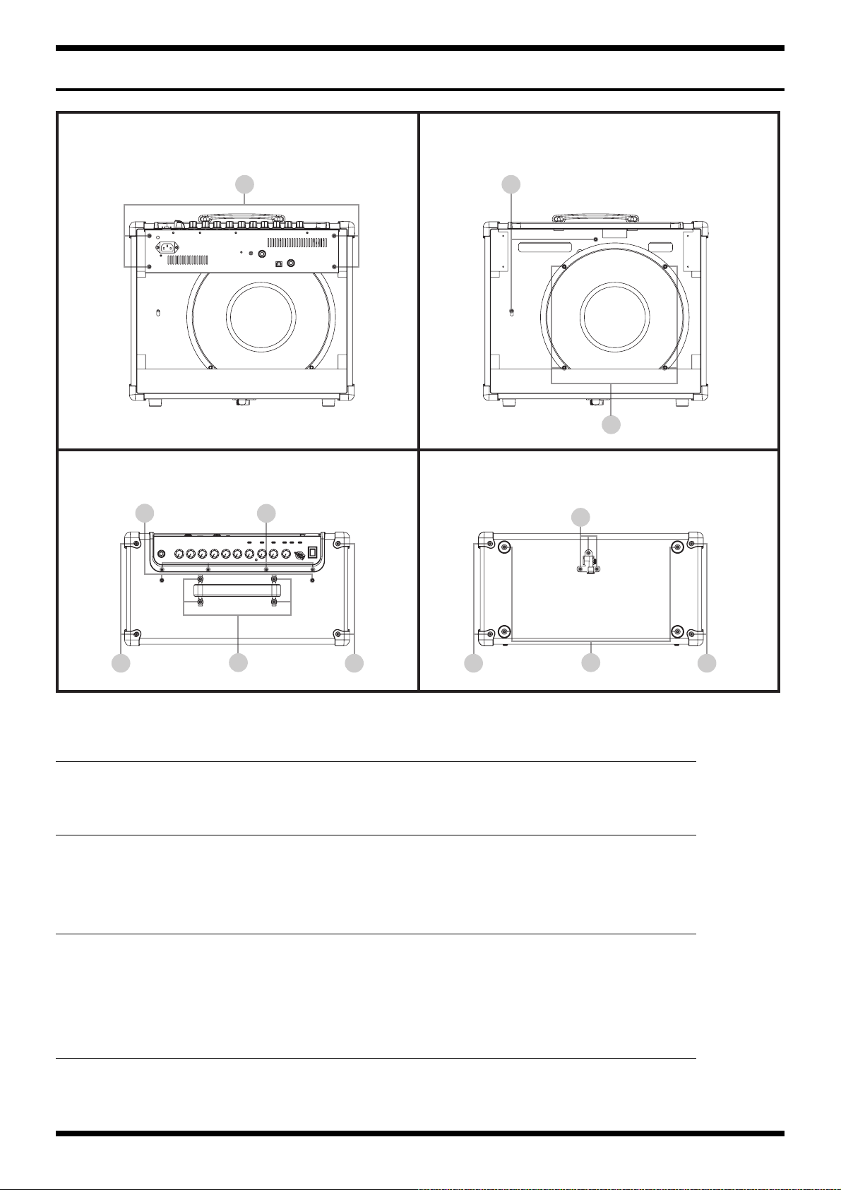
Plain View (Cabinet: 1)
fig.heimenzu-cabinet-1.eps
View 1 View 2
a y
p
View 3 View 4
c
d d d d
View 1
No. Part Code Part Name Description Q’ty
a 40010689 SCREW 4X25 TRUSS TAPPING A FE BZC 4
View 2
No. Part Code Part Name Description Q’ty
p 40010390 SCREW M5X25 BINDING HEAD FE BZC 4
y 5100053056 NUT M4 W/SW BZC 2
5100053055 PLAIN WASHER 4.2X14X1.0 BZC 2
b
e
f
g
View 3
No. Part Code Part Name Description Q’ty
b 5100053052 SCREW 3X14 TRUSS TAPPING A BZC 4
c 5100041078 ROSETTE WASHER M4 NI (MC-15042-20303-000) 2
5100047173 SCREW M4X25 OVAL MACHINE NI 2
d 5100043887 SCREW 3.5X16 TRUSS TAPPING A NI 4
e 5100048333 SCREW M4X15 OVAL MACHINE NI 4
View 4
No. Part Code Part Name Description Q’ty
d 5100043887 SCREW 3.5X16 TRUSS TAPPING A NI 4
f 40012145 SCREW 4X14 TRUSS TAPPING A FE BZC 3
g 5100024107 SCREW 4X16 BINDING TAPPING A FE BZC 4
8
Page 9

Oct. 2016 KTN-50
Plain View (Cabinet: 2)
fig.heimenzu-cabinet-2.eps
View 5 View 6
d d
View 7 View 8
t
k
View 5, 6
No. Part Code Part Name Description Q’ty
d 5100043887 SCREW 3.5X16 TRUSS TAPPING A NI 8
View 7
No. Part Code Part Name Description Q’ty
k 5100033930 SCREW 4X25 TRUSS TAPPING A NI 4
5100053053 PLAIN WASHER 4.2X14X1.0 NI 4
View 8
No. Part Code Part Name Description Q’ty
t 40011323 SCREW 3X10 BINDING TAPTITE P BZC 3
40457245 PLAIN WASHER 3X12X1 ZC 3
9
Page 10

Oct. 2016 KTN-50
Exploded View (Chassis)
fig.bunkai-chassis.eps
View 1
1
28
27
c
d
b
a
2
4
5
6
View 2
24
View 5
23
18
19
View 7
22
16
15
13
21
13
11
20
10
View 6
9
d
25
14
View 8
17
View 3
27
c
26
8
29
e
30
f
10
View 4
Page 11

Oct. 2016 KTN-50
Exploded View Parts List (Chassis)
No. Part Code Part Name Description Q’ty
1 5100052214 R-KNOB INDEX 10
2 5100049813 INDEX KNOB 1
4 02897801 SEESAW SWITCH SDDJE13200 94V-0 1
5 5100046595 POWER SW ESCUTCHEON 1
6 5100046598 POWER SW CUSHION 2
8 5100051443 AC INLET M1909-C 1
9 5100052208 CHASSIS 1
10 5100052218 S-KEYTOP 6
11 5100052217 C-KEYTOP 1
13 5100046593 JACK SPACER 3
5100051560 PANEL SHEET ASSY 1
14 ******** PANEL BOARD 1
15 ******** INPUT BOARD 1
16 ******** JACK BOARD 1
17 ******** FUSE BOARD 1
18 ******** AMP BOARD 1
19 5100051571 MAIN BOARD ASSY 1
20 5100051957 POWER TRANSFORMER 100/117V for low voltage 1
21 5100052247 TRANS SHEET 1
22 5100052219 CHASSIS COVER BOARD 1
23 5100052288 POWER IC SHEET 1
24 5100052223 HEATSINK 1
25 5100049090 CU-CR-F 16X9X0.5 1
26 5100053011 EVA PACKING 155X10X0.5 W/ADH 1
27 5100052229 TOP CUSHION S 2
28 5100052228 TOP CUSHION L 1
29 40013812 CAUTION SEAL IEC #142
30 12199584 GROUNDING TERMINAL M1698 1
* This unit includes the following parts.
5100051960 POWER TRANSFORMER 225/240V for high voltage 1
a ******** VR NUT (M7) attached to VR 1
b ******** VR NUT (M9) attached to VR 10
c ******** JACK NUT attached to JACK 3
d ******** JACK WASHER attached to JACK 3
e 5100050484 HEX NUT M4 W/SPW ZC 1
f 40011889 EXTERNAL TOOTH WASHER M4 FECM 1
11
Page 12
Oct. 2016 KTN-50
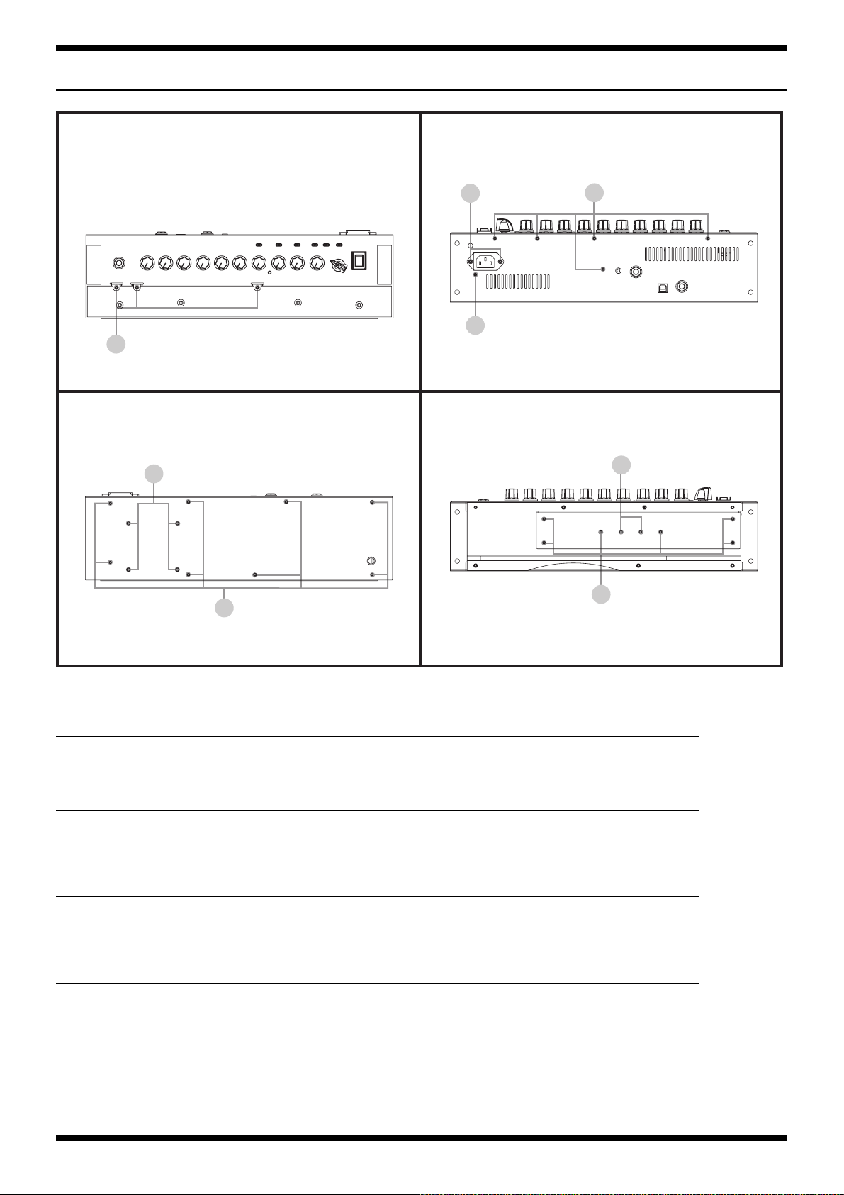
Plain View (Chassis: 1)
fig.heimenzu-chassis-1.eps
View 1 View 2
j
i
h
View 3 View 4
l
i
i
n
m
View 1
No. Part Code Part Name Description Q’ty
h 40011423 SCREW M3X6 PAN SEMS FECM 3
View 2
No. Part Code Part Name Description Q’ty
i 40012945 SCREW M3X6 PAN MACHINE W/SW+PW BZC 6
j 40011156 SCREW 3X8 FLAT TAPTITE B BZC 2
View 3
No. Part Code Part Name Description Q’ty
i 40012945 SCREW M3X6 PAN MACHINE W/SW+PW BZC 8
l 40013001 SCREW M4X8 PAN MACHINE W/SW+PW BZC 4
View 4
No. Part Code Part Name Description Q’ty
m 5100005098 SCREW 3X16 TRUSS TAPPING A BZ 3-939039-023298 6
n 40011789 NUT M3 HEX ZC 2
12
Page 13

Oct. 2016 KTN-50
Plain View (Chassis: 2)
fig.heimenzu-chassis-2.eps
View 5 View 6
o
o
View 7 View 8
r
z
r
View 5, 6
No. Part Code Part Name Description Q’ty
o 40564556 SCREW M3X15 PAN MACHINE W/SW FW ZC 9
View 7
No. Part Code Part Name Description Q’ty
r 40017934 SCREW M3X6 PAN MACHINE W/SW+PW(L) FE ZC 6
22150501 STAND OFF M3-L5.5-H10 (BS) 6
View 8
No. Part Code Part Name Description Q’ty
z 40017934 SCREW M3X6 PAN MACHINE W/SW+PW(L) FE ZC 2
22150517 STANDOFF M3 L8 2
13
Page 14
Oct. 2016 KTN-50
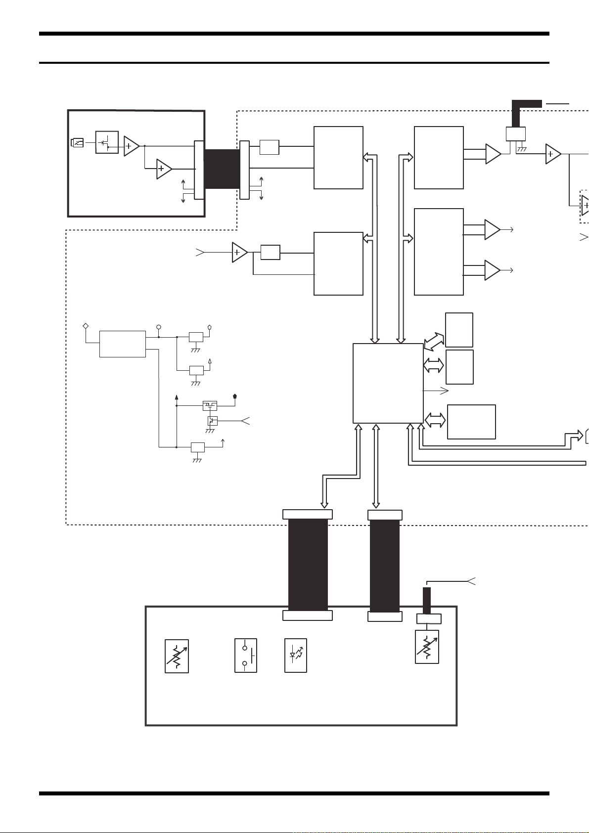
INPUT BOARD MAIN BOARD
INPUT
+AVcc
-AVcc
CN400
W4
LOW-GAIN+
HI-GAIN-
LOW-GAIN+
HI-GAIN-
ADC
AK5720
ADC
AK5720
DAC
AK4385
DAC
AK4482
RETURN
R-ATT
R-ATT
BAL
BAL
BAL
To PA
CN5
W3
P-ON_MUTE
SIG_LINE OUT
SIG_SEND
HEA
+DVcc
D+3.3V
+6V
DC-DC Converter
BD9851EFV
Reg.
D+1.2V
Reg.
FC+5V
Reg.
CODEC+5V
LED+3.3V
LED+3.3_CTL
IC3
SERIAL FLASH
8Mbit
CPU_MUTE
IC2
W-RAM
64Mbit
IC11
E-RAM
64Mbit
VOL
x 10
PANEL BOARD
From MAIN BOARD
CN5
TACT SW
x 7
LED
Single x 4
Bi-color x 3
ANALOG
x 1
CN502
W3
CN501
CN500
CN3
CN1
W5
W6
+AVcc
-AVcc
CN7
DSP, CPU
Wiring Diagram/Block Diagram
fig.wiring-KTN50.eps@L
14
Page 15

Oct. 2016 KTN-50
AMP BOARD
W7
SIG_PHONES
SIG_AUX IN-Lch
SIG_PHONES
SIG_MAIN
FUSE BOARD
Transformer
Power Switch
AC Cord
W8
W9
W17
GLASS FUSE
Pri. Sec.
CN900
CN700
CN4
+PVcc
+PVcc
-PVcc
J1 J2
-PVcc
CN9
+DVcc
-AVcc
+AVcc
PHONES/REC OUT
AUX IN
CN602
CN6
SIG_AUX IN-Rch
SIG_LINE OUT
SIG_SEND
JACK BOARD
+PVcc
-PVcc
CN8
CN11
W10
USB
FOOT SWITCH
(EXP/CH SEL)
SIG_MAIN
P-ON or CPU_MUTE
SIG_MAIN
P-ON or CPU_MUTE
INT. SPEAKER
4 ohm
W2
W1
Red
Black
-
+
fig.wiring-KTN50.eps@R
No. Part Code Part Name Description Q’ty
W1 5100051867 WIRING W1 (1015#22-RED) 1
W2 5100051868 WIRING W2 (1015#22-BLK) 1
W3 5100051869 WIRING W3 (2547#28) 1
W4 5100051870 WIRING W4 (1007#28/2547#28) 1
W5 5100051871 WIRING 1007#28 12X130-PHR-SAN-F 1
W6 5100051872 WIRING 1007#28 14X120-PHR-SAN-F 1
W7 5100051873 WIRING W7 (1007#28/2547#28) 1
W8 5100051875 WIRING W8 (1672#22-BLK/WHT) 1
W9 5100051877 WIRING W9 (1672#22-BLK) 1
W10 5100051879 WIRING W10 (1430#24/1185#26) 1
W17 5100048516 WIRING W17 (1015#18-GRN&YEL) 1
15
Page 16

Oct. 2016 KTN-50
Parts List
fig.-part1-e.eps
Safety Precautions:
The parts marked have
safety-related characteristics. Use
only listed parts for replacement.
Note: The parts marked # are new. (initial parts) The description “Q’ty” means a necessary number of the parts per one product.
CASING
# 5100053344 CABINET ASSY W/O SPEAKER 1
CHASSIS
# 5100052208 CHASSIS 1
# 5100052219 CHASSIS COVER BOARD 1
KNOB, BUTTON
# 5100052214 R-KNOB INDEX 10
# 5100052217 C-KEYTOP 1
# 5100052218 S-KEYTOP 6
SWITCH
JACK, EXT TERMINAL
# 5100050453 3.5MM JACK HSJ2000-01-010 1
5100049813 INDEX KNOB 1
02897801 SEESAW SWITCH SDDJE13200 94V-0 1
01780101 TACT SWITCH SKQKABD010 7
5100031944 6.5MM JACK PJ-644C-EP 2
5100024419 6.5MM JACK PJ-644C-04-EP(610-11020-01-00 1
5100009531 USB CONNECTOR B TYPE FEMALE YKF45-0044N 1
Due to one or more of the following reasons, parts with parts code ******** cannot be supplied
as service parts.
• Supply is prohibited due to copyright restrictions.
• It is carried in electronic data on the Roland web site.
• The part is made to order (at current market price).
• It can be replaced with an article on the market. (battery or etc.)
• It is a package or an accessory irrelevant to the function maintenance of the main body.
• A number of circuit boards are grouped together and supplied as a single circuit board (under a different part code).
• Reissuance is restricted.
• It is supplied as an assembled part
(under a different part code).
SPEAKER, BUZZER
# 5100052293 SPEAKER W1204-067A 1
PWB ASSY
# 5100051571 MAIN BOARD ASSY 1
# 5100051560 PANEL SHEET ASSY 1
DIODE
POTENTIOMETER
# 5100052460 ROTARY POTENTIOMETER RD901F-40-15F-B10K-05D60A 1
# 5100052466 ROTARY POTENTIOMETER RD901F-40-125F-B10K-04D60A 1
# 5100052467 ROTARY POTENTIOMETER RD901F-40E1-15F-0B10K-00D86A 8
FUSE, FUSE HOLDER
WIRING, CABLE
# 5100051871 WIRING 1007#28 12X130-PHR-SAN-F 1
# 5100051872 WIRING 1007#28 14X120-PHR-SAN-F 1
# 5100051867 WIRING W1 (1015#22-RED) 1
# 5100051868 WIRING W2 (1015#22-BLK) 1
# 5100051869 WIRING W3 (2547#28) 1
# 5100051870 WIRING W4 (1007#28/2547#28) 1
# 5100051873 WIRING W7 (1007#28/2547#28) 1
* This unit includes the following parts.
******** PANEL BOARD 1
******** AMP BOARD 1
******** JACK BOARD 1
******** INPUT BOARD 1
******** FUSE BOARD 1
5100003359 LED(RED) L-34ID (153-L-34IDSLLF) 4
05011067 LED L-3WEGW (153-L-3WEGW) 3
5100022034 ROTARY POT(231-11017-03-00) RD901F-40E1-15F-1B20K-00DN6 1
03670534 FUSE 5ST 1.25 1.25A/250V for low voltage 1
03674001 FUSE 5ST 630MA/250V for high voltage 1
16
Page 17

Oct. 2016 KTN-50
WIRING, CABLE
# 5100051875 WIRING W8 (1672#22-BLK/WHT) 1
# 5100051877 WIRING W9 (1672#22-BLK) 1
# 5100051879 WIRING W10 (1430#24/1185#26) 1
TRANSFORMER
# 5100051957 POWER TRANSFORMER 100/117V for low voltage 1
# 5100051960 POWER TRANSFORMER 225/240V for high voltage 1
AC INLET, OUTLET
# 5100051443 AC INLET M1909-C 1
5100048516 WIRING W17 (1015#18-GRN&YEL) 1
SCREWS
# 5100053052 SCREW 3X14 TRUSS TAPPING A BZC 4
# 5100053056 NUT M4 W/SW BZC 2
# 5100053055 PLAIN WASHER 4.2X14X1.0 BZC 2
# 5100053053 PLAIN WASHER 4.2X14X1.0 NI 4
MISCELLANEOUS
# 5100052237 BOSS BADGE 1
# 5100053891 KATANA BADGE 1
# 5100052235 TRIM SASH 1
# 5100052238 CORNER PROTECTOR 8
# 5100052242 STAND FOOT 1
# 5100052244 STAND HOLDER 1
# 5100052241 STAND PIN 1
# 5100052240 STAND ROD 1
# 5100052243 STAND RUBBER 1
# 5100052223 HEATSINK 1
# 5100051747 LED SPACER LH-5-1.5 4
# 5100051955 POWER IC HOLDER 1
# 5100052228 TOP CUSHION L 1
# 5100052229 TOP CUSHION S 3
# 5100052288 POWER IC SHEET 1
# 5100052247 TRANS SHEET 1
# 5100053011 EVA PACKING 155X10X0.5 W/ADH 1
# 5100053271 EVA PACKING 240X15X0.5 W/ADH 1
# 5100052278 LABEL SPEAKER MAGNET 1
40011423 SCREW M3X6 PAN SEMS FECM 3
40017934 SCREW M3X6 PAN MACHINE W/SW+PW(L) FE ZC 8
40012945 SCREW M3X6 PAN MACHINE W/SW+PW BZC 14
40564556 SCREW M3X15 PAN MACHINE W/SW FW ZC 9
40013001 SCREW M4X8 PAN MACHINE W/SW+PW BZC 4
5100048333 SCREW M4X15 OVAL MACHINE NI 4
5100047173 SCREW M4X25 OVAL MACHINE NI 2
40010390 SCREW M5X25 BINDING HEAD FE BZC 4
40011156 SCREW 3X8 FLAT TAPTITE B BZC 2
40011323 SCREW 3X10 BINDING TAPTITE P BZC 3
5100005098 SCREW 3X16 TRUSS TAPPING A BZ 3-939039-023298 6
5100043887 SCREW 3.5X16 TRUSS TAPPING A NI 16
40012145 SCREW 4X14 TRUSS TAPPING A FE BZC 3
5100024107 SCREW 4X16 BINDING TAPPING A FE BZC 4
40010689 SCREW 4X25 TRUSS TAPPING A FE BZC 4
5100033930 SCREW 4X25 TRUSS TAPPING A NI 4
5100007512 THUMB SCREW (FOR REPAIR ONLY) 1
22150501 STAND OFF M3-L5.5-H10 (BS) 6
22150517 STANDOFF M3 L8 2
40011789 NUT M3 HEX ZC 2
5100050484 HEX NUT M4 W/SPW ZC 1
40457245 PLAIN WASHER 3X12X1 ZC 3
40011889 EXTERNAL TOOTH WASHER M4 FECM 1
5100041078 ROSETTE WASHER M4 NI (MC-15042-20303-000) 2
5100049817 HANDLE 1
5100041039 FOOT EK1206 4
5100000592 FUSE HOLDER FC-201(613-11617-01-00) 2
12199584 GROUNDING TERMINAL M1698 9
40016523 INSULOK TIE 100M/M T-18R (1000 PCS ORDERING PER) 10
5100046593 JACK SPACER 3
5100046595 POWER SW ESCUTCHEON 1
5100046598 POWER SW CUSHION 2
5100049090 CU-CR-F 16X9X0.5 1
40013812 CAUTION SEAL IEC #142 1
17
Page 18

Oct. 2016 KTN-50
ACCESSORIES (Standard)
# 5100052281 OWNER’S MANUAL MULTILANGUAGE 1
03340956 AC CORD SET PSE 100V YA-101/YP-3NB/YC-13 for 100V 1
5100029165 AC CORD 115TW 2.5M SP301+IS14 VCTF for 115VTW 1
5100012292 AC CORD SET 117VBL 2.5M 3P DAIKEI 117VBL for 117VBL 1
00894378 AC CORD SET 120V SP301+IS14 SJT18/3 for 117VU, 117VUC/S 1
03450323 AC CORD SET 220V YP-36 YC-13D for 220VCN 1
5100013648 AC CORD SET 220VK 10A 3P-3P 2.5M for 220VK 1
00907001 AC CORD SET 240VE SP-62+IS-14 for 230VE 1
00894389 AC CORD SET 230V SP22+IS14 H05VV-F3G1.0 for 230VEU 1
5100013842 AC CORD SET 240VA 2.5M SAA HIRAKAWA for 240VA 1
18
Page 19

Oct. 2016 KTN-50
Verifying the Version
Carry out verification in Test Mode (p. 20).
Data Backup and Restore Operations
The Tone Setting saved in CH1, CH2 on the panel can be saved by
following procedures.
The PANEL Settings cannot be backed up. Therefore, in case the Main
Board is replaced or the Factory Reset is performed, the PANEL Settings
will be lost.
Items Required
•Computer
•USB cable
• MIDI sequence program (Cakewalk Sonar LE or etc.)
* Install this to the computer above.
• Driver for KATANA.
* Obtain this from the following web page, and install it on the computer just
described.
http://www.roland.com/global/
System Update Procedure
Items Required
•Computer
•USB cable
• Update file (obtained via Service Net)
Procedure
1. Hold down CH1 and PANEL and switch on the power.
CH1 and CH2 flash.
2. Connect the computer to the USB connector.
The buttons that flashed in Step 1 light up constantly, and the computer
screen shows BOSS_KATANA drive.
3. Copy the update file (*.BIN, ROMINFO.TXT) to the root folder on the
BOSS_KATANA drive.
4. Unmount the BOSS_KATANA drive and disconnect the USB cable.
PANEL flashes.
5. Press PANEL.
BOOSTER/MOD, DELAY/FX, and REVERB light up in green, and the
update starts.
While updating is in progress, BOOSTER/MOD, DELAY/FX, and
REVERB light up in order of red, green, and orange.
* Never switch off the power while the update is in progress. Doing so might make
the unit impossible to start.
Data Backup
1. Connect the computer to the USB connector.
2. Launch the MIDI sequence software on the computer, and set the MIDI
input and output device to KATANA.
3. Create two MIDI tracks (Track 1, Track 2) and input the following SysEx
data to the Track 1.
F0 41 00 00 00 00 33 11 00 00 00 00 20 00 00 00 60 F7
4. Set the Track 2 to standby for recording, and start the recording and the
playback.
The SysEx of the Step 3 is transmitted to the amp, and the amp that
received it transmits all the user data to the MIDI sequencer.
The transmission of the user data completes in several seconds.
* There are no change on the amp’s display.
5. Stop the MIDI sequencer, mute or delete the Track 1, set the Track 2 to
playback, and save the file.
The backup procedure is finished now.
6. Disconnect the USB cable.
Data Restore Operations
1. Connect the computer to the USB connector.
2. Launch the MIDI sequence software on the computer, and set the MIDI
input device to KATANA.
3. Load the backed-up file and transmit it to the amp.
The transmission of the user data completes in several seconds.
* There are no change on the amp’s display.
4. Stop the MIDI sequencer.
The restore procedure is finished now.
5. Disconnect the USB cable.
If BOOSTER/MOD, DELAY/FX, and REVERB turn green, and slowly
flash simultaneously, then the updating is completed.
* If the update did not finish correctly, then these three buttons flash in fast cycle.
6. Switch off the power.
Performing a Factory Reset
1. Hold down PANEL and switch on the power.
2. If any of the buttons light up or flash, then release your finger.
The Factory Reset starts, and BOOSTER/MOD, DELAY/FX and REVERB
light up and turn dark in sequence.
When PANEL flashes, the factory reset has finished.
3. Switch off the power.
19
Page 20
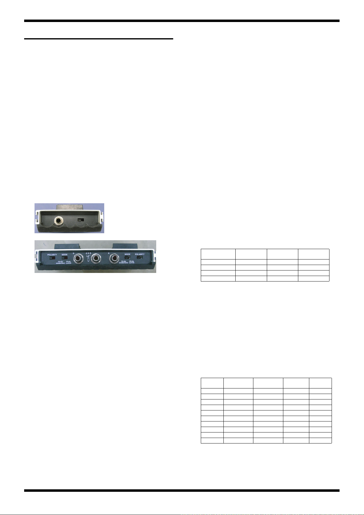
Oct. 2016 KTN-50
FS-5U
FS-6
Test Mode
Items Required
•Computer
• Oscillator
• Oscilloscope
•Noise meter
• FS-5U (x 2) or FS-6 (x 1)
• Y cable (having one 1/4-inch stereo phone plug and two 1/4-inch
monaural phone plugs) or 1/4-inch stereo phone cable
• 1/4-inch stereo phone cable
• 1/4-inch stereo phone cable with 33 Ω load resistors (connected 33 Ω load
resistors to each location between L-GND and between R-GND)
•USB cable
• Monaural phone short plug
• Load resistor (4 Ω, 300 W)
• KATANA USB driver
* Obtain this from the following web page, and install it on the computer just
described.
http://www.roland.com/global/
* Set the POLARITY switch and the MODE switch on the foot switch as shown
below.
fig.FS-5U.eps
Test Items
1. Model Check (p. 20)
2. Version Check (p. 20)
3. Switch / LED Check (p. 21)
4. Selector Check (p. 21)
5. Volume Check (p. 21)
6. Jack Sense & Foot Switch Check (p. 22)
7. USB Check (p. 22)
8. Device Check (p. 22)
9. Signal Level Check (p. 22)
10. Noise Check (p. 23)
Skipping Test Items
While you are in 1. Model Check (p. 20) or 2. Version Check (p. 20), you
can skip to each test items with following procedure.
•Press PANEL: This skips to 3. Switch / LED Check (p. 21).
•Press PANEL and BOOSTER/MOD simultaneously:
This skips to 5. Volume Check (p. 21).
•Press PANEL and DELAY/FX simultaneously:
This skips to 6. Jack Sense & Foot Switch Check (p.
22).
•Press PANEL and REVERB simultaneously:
This skips to 8. Device Check (p. 22).
•Press PANEL and CH1 simultaneously:
This skips to 9. Signal Level Check (p. 22).
fig.FS-6.eps
* Do not take the earth off from the measuring devices such as oscilloscope and
noise meter. (2P connection)
* In case of using a measuring device with multiple inputs, use only one input and
do not feed any signals to the other jacks. Or else, the internal circuit of this
product may be damaged.
Entering the Test Mode
1. Turn all knobs except AMP TYPE all the way counterclockwise.
2. Hold down CH1 and CH2 and switch on the power.
TAP, CH1, CH2, and PANEL light up.
3. Release your finger.
After three EFFECTS buttons, TAP, CH1, CH2, and PANEL flash twice,
you’ll enter the first test item (1. Model Check (p. 20)).
* If you are proceeding to 9. Signal Level Check (p. 22), 10. Noise Check (p.
23), then disconnect the speaker cable from the speaker, and attach a load resistor
(4 Ω, 300 W) to the speaker terminals (between red and black), BEFORE going
into the Test Mode.
* Be very careful so that the speaker terminals never touch to the other conductive
portion.
Quitting the Test Mode
Switch off the power.
1. Model Check
As shown on the following chart, one of the three EFFECTS buttons
lights up in green or red, and shows the model.
BOOSTER/
KTN-50 G - KTN-100 - G KTN100/212 - R KTN-HEAD - - G
R: Lit in red, G: Lit in green, -: Turns dark
* If the LED shown above does not match with the model name sticker on the rear
panel, then the wrong main board is being installed.
MOD
DELAY/FX REVERB
2. Version Check
1. Adjust the POWER CONTROL knob to 0.5 W, and keep pressing TAP.
As shown on the following chart, TAP and three EFFECTS buttons light
up or turn dark while pressing TAP, the one’s digit value of the version
number is shown in binary numbers.
* When pressing TAP, be sure to press it with the tip of your fingernail, and verify
the light up or turning dark of the TAP itself.
TAP BOOSTER/
- - - - 0
- - - o 1
- - o - 2
- - o o 3
- o - - 4
- o - o 5
- o o - 6
- o o o 7
o - - - 8
o - - - 9
o: Light, -: Turns dark
MOD
DELAY/FX REVERB Value
20
Page 21

Oct. 2016 KTN-50
2. Adjust the POWER CONTROL knob to 25 W.
Likewise, while pressing TAP, the value of the first decimal place of the
version number is shown in binary numbers.
3. Adjust the POWER CONTROL knob to 50 W.
Likewise, while pressing TAP, the value of the second decimal place of
the version number is shown in binary numbers.
4. Return the POWER CONTROL knob to STANDBY.
5. Press PANEL to proceed to the next test item.
3. Switch / LED Check
BOOSTER/MOD flashes in red, TAP and DELAY/FX–PANEL light up in
red.
1. Press BOOSTER/MOD.
BOOSTER/MOD flashes in green.
2. Press BOOSTER/MOD.
BOOSTER/MOD turns dark, and DELAY/FX flashes in red.
3. Press DELAY/FX.
DELAY/FX flashes in green.
4. Press DELAY/FX.
DELAY/FX turns dark, and REVERB flashes in red.
5. Press REVERB.
REVERB flashes in green.
6. Press REVERB.
REVERB turns dark, and CH1 flashes in red.
7. Press CH1.
CH1 turns dark, and CH2 flashes in red.
8. Press CH2.
CH2 turns dark, and PANEL flashes in red.
9. Press PANEL.
PANEL turns dark, and TAP flashes in red.
10. Press TAP to proceed to the next test item.
4. Selector Check
BOOSTER/MOD lights up in red.
1. Slowly turn the AMP TYPE knob one click at a time in order of the numbers shown in the table, and verify the status of the LEDs.
Initial state ACOUSTIC R - -
Knob position BOOSTER/MOD DELAY/FX REVERB
1 CLEAN R R 2 CRUNCH G G 3 LEAD G G R
4 BROWN G G G
5 LEAD G G R
6 CRUNCH G G 7 CLEAN R R 8 ACOUSTIC R - -
R: Lit in red, G: Lit in green, -: Turns dark
Button
5. Volume Check
1. Slowly turn the GAIN knob in order of the numbers shown in the table, and verify the status of the LEDs of the each buttons.
Initial state Minimum R - -
Knob position BOOSTER/MOD DELAY/FX REVERB
1 8 o’clock R R 2 12 o’clock G G 3 12 o’clock–maximum G G G
4 Maximum G* G* G*
R: Lit in red, G: Lit in green, G*: Flashes in green, -: Turns dark
After flashing in green, BOOSTER/MOD lights up in red, other two buttons turn dark, and proceed to the next volume check.
2. Likewise, from the Volume knob to the REVERB knob needs also to be checked from left to right.
* If you turn the wrong knob, then the three buttons flash. In this case, turn the correct knob to continue the inspection.
3. Slowly turn the POWER CONTROL knob in order of the table shown, and verify the status of the LED.
Knob position BOOSTER/MOD DELAY/FX REVERB
Initial state STANDBY R - 1 0.5 W R R 2 25 W R R R
3 50 W G G G
4 25 W G G 5 0.5 W G - 6 STANDBY R - -
R: Lit in red, G: Lit in green, -: Turns dark
Button
Button
When the POWER CONTROL knob is returned to STANDBY, it automatically proceeds to the next test item.
21
Page 22

Oct. 2016 KTN-50
6. Jack Sense & Foot Switch Check
PANEL lights up.
Also, BOOSTER/MOD flashes, DELAY/FX and REVERB light up.
1. Connect the monaural phone short plug (or the monaural phone dummy
plug) to the INPUT jack.
BOOSTER/MOD lights up.
2. Disconnect the plug.
BOOSTER/MOD turns dark, and DELAY/FX flashes.
3. Connect the monaural phone short plug (or the monaural phone dummy
plug) to the PHONES/REC OUT jack.
DELAY/FX lights up.
4. Disconnect the plug.
DELAY/FX turns dark, and REVERB flashes.
5. Connect the FS-5U or FS-6 to the FOOT CONTROL jack.
REVERB lights up. And BOOSTER/MOD flashes, DELAY/FX lights up.
6. Press the Tip side pedal of the FS-5U or FS-6.
BOOSTER/MOD turns dark, and DELAY/FX flashes.
7. Press the Ring side pedal of the FS-5U or FS-6.
DELAY/FX turns dark.
8. Disconnect the plug from the FOOT CONTROL jack.
REVERB turns dark, and it automatically proceeds to the next test item.
7. USB Check
PANEL flashes.
1. Connect the computer to the USB connector.
PANEL lights up.
2. Disconnect the USB cable.
PANEL turns dark, and it automatically proceeds to the next test item.
8. Device Check
Entering the Test Mode, the Device Check runs automatically in the
background and the results are shown by entering this test item.
If they are OK, then three EFFECTS buttons flash in green, and it
automatically proceeds to the next test item.
If they are not OK, then the buttons corresponding to the NG (not OK)
devices as shown below flash.
SFlash: BOOSTER/MOD (red)
SDRAM (CPU): DELAY/FX (red)
DSP: REVERB (red)
SDRAM (DSP ERAM): CH1
Program Sum: CH2
Sensor: TAP
9. Signal Level Check
INPUT -> PHONES L/R
BOOSTER/MOD, CH1 and CH2 light up. (AF Hi)
1. Turn the MASTER knob to minimum, and POWER CONTROL knob to
STANDBY.
2. If the eight knobs from GAIN to REVERB are not turned to maximum,
then turn them all to maximum.
3. Connect the oscilloscope and the noise meter to the PHONES/REC OUT
jack (L).
* Connect a 1/4-inch stereo phone plug with 33 Ω load resistors to the PHONES/
REC OUT jack.
4. Connect the oscillator to the INPUT jack and input a signal like the
following.
INPUT: 1-kHz sine wave at -40 dBm
* Do not input the signal (sine wave) continuously for over five minutes or else
the product may get damaged. This is the same in the following steps.
5. Verify that no signal is output from the PHONES/REC OUT jack (L).
6. Adjust the MASTER knob to center. (AF Hi)
7. Verify that a signal like the following is output from the PHONES/REC
OUT jack (L).
PHONES L: 1-kHz sine wave at -7.0±1.5 dBm (flat)
8. Adjust th MASTER knob to maximum, and the VOLUME knob to
minimum. (AF Hi)
9. Verify that a signal like the following is output from the PHONES/REC
OUT jack (L).
PHONES L: 1-kHz square wave at +8.5±1.5 dBm (flat)
10. Adjust the VOLUME knob to maximum and press BOOSTER MOD.
BOOSTER MOD lights up in green. (AF-Lo)
11. Verify that a signal like the following are output from the PHONES/REC
OUT jack (L).
PHONES L: 1-kHz sine wave at -29.5±1.5 dBm (flat)
12. Connect the oscilloscope and the noise meter to the PHONES/REC OUT
jack (R).
* Connect a 1/4-inch stereo phone plug with 33 Ω load resistors to the PHONES/
REC OUT jack.
13. Connect the oscillator to the INPUT jack and input a signal like the
following.
INPUT: 1-kHz sine wave at -20 dBm
14. Verify that a signal like the following is output from the PHONES/REC
OUT jack (R).
PHONES R: 1-kHz sine wave at -9.0±1.5 dBm (flat)
15. Disconnect the plug from the PHONES/REC OUT jack.
AUX IN -> Speaker
1. Disconnect the speaker terminals from the speaker, and attach a load
resistor (4 Ω, 300 W) to the speaker terminals (between red and black).
2. Connect the oscilloscope and the noise meter to the speaker terminals.
* Connect the black line to the GND of the measuring device, and red line to the
signal line.
3. Connect the oscillator to the AUX IN jack and input a signal like the
following to both L and R simultaneously.
AUX IN L/R:100-Hz sine wave at -20 dBm
4. Adjust the POWER CONTROL knob to 50 W, and the MASTER knob to
maximum.
* When feeding the signal, do not leave the POWER CONTROL knob to
positions other than STANDBY for over five minutes, or else the product may
get damaged. If the testing takes time, return it to STANDBY for a while. This
is the same in the following steps.
5. Verify that a signal like the following is output from the speaker
terminals.
Speaker: 100-Hz sine wave at +19.5±1.5 dBm (flat)
6. Input a signal like the following to the AUX IN jack. (change the
frequency)
AUX IN L/R:10-kHz sine wave at -20 dBm
7. Verify that a signal like the following is output from the speaker
terminals.
Speaker: 10-kHz sine wave at +24.5±1.5 dBm (flat)
8. Input a signal like the following to the AUX IN jack. (change the
frequency)
AUX IN L/R:1-kHz sine wave at -20 dBm
9. Verify that a signal like the following is output from the speaker
terminals.
Speaker: 1-kHz sine wave at +18.0±1.5 dBm (flat)
10. Adjust the POWER CONTROL knob to 25 W.
22
Page 23

Oct. 2016 KTN-50
11. Verify that a signal like the following is output from the speaker
terminals.
Speaker: 1-kHz sine wave at +12.5±1.5 dBm (flat)
12. Adjust the POWER CONTROL knob to 0.5 W.
13. Verify that a signal like the following is output from the speaker
terminals.
Speaker: 1-kHz sine wave at -2.0 ±1.5 dBm (flat)
14. Adjust the POWER CONTROL knob to STANDBY.
15. Verify that no signal is output from the speaker terminals.
16. Disconnect the oscillator.
* The load resistor of the speaker terminals is continued to be attached for the next
test item.
Waveform (Speaker/PHONES)
1. Connect the oscillator to the INPUT jack and input a signal like the
following.
INPUT: 1-kHz sine wave at -10 dBm
2. Adjust the POWER CONTROL knob to 50 W, and the MASTER knob to
maximum.
3. Verify that the waveform of the signal output from the speaker terminals
is as follows.
fig.test-wave-1.eps
10. Noise Check
1. Connect a 1/4-inch monaural phone short cable to the INPUT jack.
2. Turn all knobs clockwise all the way.
3. Attach a load resistor (4 Ω, 300 W) to the speaker terminals. (between red
and black)
4. Connect the noise meter to the speaker terminals and verify that residual
noise is as follows.
Speaker: -42 dBm or less (DIN-Audio)
5. Connect the noise meter to the PHONES/REC OUT jack (L).
* Connect a 1/4-inch stereo phone plug with 33 Ω load resistors to the PHONES/
REC OUT jack.
6. Verify that residual noise at the PHONES/REC OUT jack (L) is as follows.
PHONES L: -70 dBm or less (DIN-Audio)
4. Detach the oscilloscope and the noise meter.
* Be very careful so that the speaker terminals never touch to the other conductive
portion.
5. Connect the oscilloscope to the PHONES/REC OUT jack (L).
* Connect a 1/4-inch stereo phone cable with 33 Ω load resistors to the PHONES/
REC OUT jack.
6. Input a signal like the following to the INPUT jack.
INPUT: 1-kHz sine wave at 0 dBm
7. Verify that the waveform of the signal output from the PHONES/REC
OUT jack (L) is as follows.
fig.test-wave-2.eps
8. Disconnect the plug from the INPUT, and PHONES/REC OUT jacks.
9. Press BOOSTER/MOD.
BOOSTER/MOD lights up in green.
23
Page 24

Oct. 2016 KTN-50
Circuit Board (Main Board)
fig.b-main-1.eps
24
Page 25

Oct. 2016 KTN-50
fig.b-main-2.eps
25
Page 26

Oct. 2016 KTN-50
MA(15)
MA(14)
MA(11)
MA(10)
MA(6)
MA(5)
MA(0:11,14,15)
MD(0:15)
MD(15)
MD(14)
MD(13)
MD(12)
MD(15)
MD(14)
MD(13)
MD(12)
DG
DG
D+3.3V
D+1.2V
D+1.2V
D+3.3V
DG
XMWE
XMWR-MCAS
MCKE
DG
DG
D+3.3V
D+1.2V
DG
D+3.3V
D+3.3V
D+3.3V
D+1.2V
D+3.3V
DG
DG
DG
SFI_CK0
MCKO
D+3.3V
DG
SFI_DIN
SFI_XCS0
MA(8)
MA(4)
MA(0)
MA(1)
MA(3)
MA(2)
MA(7)
MD(10)
MD(11)
MD(8)
MD(9)
MD(4)
MD(5)
MD(6)
MD(7)
MD(0)
MD(2)
MD(3)
MD(10)
MD(11)
MD(8)
MD(9)
MD(4)
MD(6)
MD(7)
DG
D+3.3V
DG
D+3.3V
DG
XMSDRCS
XMWE
XMWR-MCAS
XMRD-MRAS
MDQM0
MDQM1
MCKE
MA(15)
MA(14)
MA(0)
MA(1)
MA(2)
MA(3)
MA(4)
MA(5)
MA(6)
MA(7)
MA(8)
MA(9)
MA(10)
MA(11)
D+3.3V
DG
VR-TYPE-PRES
XCOM
YCOM
D+3.3V
SFI_DO
MD(1)
XMSDRCS
MA(9)
DETECT-5V
DG
XRESET
XMRD-MRAS
MDQM0
D+3.3V
XRESET
D+3.3V
FC+5V
DG
DG
FC+5V
DG
FG1
FG1
DG
FC+5V
FC+5V
DG
DG
DG
FC+5V
DG
RXD2-MIDI-IN
RXD3-FC
TXD3-FC
SFI_HLD
DG
XSF-WP
DG
D+3.3V
VR-PWR-CTL
EXP-TIP
EXP-RING
DG FG2
D+3.3V
LED+3.3V-CTL
XSF-WP
D+3.3V
DG DG
MODEL-CHECK1
D+3.3V
D+3.3V
DG
MODEL-CHECK0
MODEL-CHECK0
MODEL-CHECK1
LED-FX1-RED
LED-FX1-GREEN
LED-FX2-RED
LED-FX2-GREEN
LED-FX3-RED
LED-FX3-GREEN
D+3.3V
MCKO
D+3.3V
SPOUT-MONITOR
DG
ENC-B
ENC-A
FC-VCC-CTL
MD(5)
MD(0)
MD(3)
MD(2)
MD(1)
MDQM1
RA18
UnPop
EXB28V220JX
18
6543
27
RA16
UnPop
EXB28V220JX
18
6543
27
RA17
UnPop
EXB28V103JX
18
6
54
3
27
IC6
S-80130ANMC-JCPT2G
5
VDD
2
VSS
1
DS
3
NC
4
OUT
5.5V
TC7SET04FU
IC21
UnPop
2
IN
4
OUT
1
NC
TC7SET04FU
IC21
UnPop
3
GND
5
VCC
D4
1SS387
UnPop
RA10
100
EXB28V101JX
18
6
54
3
27
RA9
100
EXB28V101JX
18
6
54
3
27
RA12
100
EXB28V101JX
18
6543
27
RA11
100
EXB28V101JX
18
6543
27
56
RA15
EXB28V560JX
18
6543
27
RA3
56
EXB28V560JX
1
8
6
5
4
3
2
7
RA4
56
EXB28V560JX
1
8
6
5
4
3
2
7
RA14
56
EXB28V560JX
18
6543
27
EXB28V560JX
RA2
56
1
8
6543
27
D16
1SS362FV
UnPop
2
3
1
C50 1uF
C21
1uF
C19
1uF
C18
1uF
C47 1uF
C30
1uF
C23
1uF
C52 1uF
C51 1uF
C49 1uF
C48 1uF
0
R30
1608
UnPop
R28
UnPop
56
1608
100
R36
UnPop
1608
100
R22
1608
UnPop
120
R37
UnPop
1608
R26
150
1608
390
R29
1608
UnPop
2.2k
R161
1608
UnPop
R5
100k
1608
R1
180k
1608
MB8AA4181(ESC2)
IC1
D1
C17
M9
M10
M11
M12
M13
M14
N10
N11
N12
N13
N14
N8
N9
P8
P9
L14
M8
T3
T4
V10
W10
Y10
D4
D18
D19
L18
L19
M3
M4
V6
V15
W6
J13
N19
N18
K4
K3
J21
J19
J18
G21
F18
F4
F1
E4
D21
D12
W15
P11
P12
P13
P14
A1
A21
AA1
AA21
D7
D17
G3
G4
G18
G19
R18
R19
P10
J14
K8
K9
K10
K11
K12
K13
K14
L8
L9
L10
L11
L12
L13
P1
J12
AA3
Y3
W21
W20
W19
W13
W8
W4
V18
V13
V8
V4
U21
P4
P3
C3
B17
A18
H8
H9
H10
H11
H12
H13
H14
J8
J9
J10
J11
AA5
IC1
MB8AA4181(ESC2)
P18
P19
Y14
AA13
Y13
AA12
W14
V14
V16
C15
D15
A15
D14
B15
A12
A14
A16
B12
M21
M20
L21
L20
M19
M18
K19
K18
H19
N20
N21
P20
P21
R20
R21
T20
T21
U19
U20
V19
V20
T18
T19
F2
C2
B1
Y1
B2
A2
C16
C12
D16
AA18
Y19
AA19
AA14
U18
V17
W16
AA15
Y15
B10
C10
A9
A11
B7
B11
B9
C9
D9
A7
D10
B8
A8
C19
C4
B6
D5
A6
C7
A3
B4
C5
D6
B14
B16
C13
D13
C14
B13
A13
H18
E18
K21
K20
H20
J20
V21
Y16
AA17
Y20
W17
Y18
Y17
AA16
W18
F3
A4
B5
C6
A5
F21
F20
E21
E20
H21
D8
C8
AA2
AA20
Y21
A17
C11
D11
A10
C20
D20
E19
F19
G20
B19
C21
B20
A20
B21
C18
B18
A19
B3
IC7
QCPL-M614-500E
UnPop
11
33
44
55
66
IC9
QCPL-M614-500E
UnPop
1
3
4
5
6
IC10
QCPL-M614-500E
UnPop
1
3
4
5
6
C46 0.1uF
C6 0.1uF
C1 0.1uF
C7
0.1uF
C3 0.1uF
C45 0.1uF
C35 0.1uF
C34 0.1uF
C59
0.1uF
C37 0.1uF
C40 0.1uF
C44 0.1uF
C4
0.1uF
C26
0.1uF
C54
0.1uF
C55
0.1uF
C24
0.1uF
C57
0.1uF
UnPop
C226
0.1uF
C41 0.1uF
C31
0.1uF
C165 0.1uF
C56
0.1uF
UnPop
C38 0.1uF
C43 0.1uF
C225
0.1uF
C39 0.1uF
C5 0.1uF
C36 0.1uF
C33 0.1uF
C2
0.1uF
C28
100pF
UnPop
C58
1000pF
1608
UnPop
C15
1uF
1608
R27
0
R35
0
R6
0
R14 10
R12 10
R16 10
R17 10
R18 10
R11 10
R13 10
R77 UnPop
R15 33
R10 56
R9 56
R19 100
R50
100
UnPop
270
R45
R216 4.7k
R215 4.7k
R33
10k
R48
10k
R44
10k
R31
10k
PJ-644C-EP
JK3
UnPop
1S
6SS
4TS
3T
R2
RS5
CN2
UnPop
BM14B-SRSS-TB (LF)(SN)
50V
1
22
33
44
55
6
8
9
10
11
12
13
14
7
IC2
M12L64164A-7TG2Y(60NM)
6
VSSQ
_WE
16
VSS
41 14
VDD
27
VDD
3
VDDQ
1
VDD
53
DQ15
51
DQ14
50
DQ13
48
DQ12
47
DQ11
45
DQ10
2
DQ0
4
DQ1
5
DQ2
7
DQ3
8
DQ4
10
DQ5
11
DQ6
13
DQ7
42
DQ8
44
DQ9
VSSQ
12
46
VSSQ
VSSQ
52
VDDQ
9
43
VDDQ
VDDQ
49
40
NC
36
NC
35
A11
22
A10/AP
34
A9
33
A8
32
A7
31
A6
30
A5
29
A4
26
A3
25
A2
24
A1
23
A0
21
BA1
28
VSS
38
CLK
37
CKE
39
UDQM
15
LDQM
18
_RAS
17
_CAS
20
BA0
_CS
19
54
VSS
10V
10uF
C110
2012
C224
10uF
2012
YKF45-0044N
JK1
3D+2
D-
1
VBUS
4
GND
10
FRAME
20
FRAME
R7 12k 1%
TP6
TP26
TP25
TP24
TP3
TP7
TP28
TP21
TP17
TP27
TP8
TP23
50V
1000pF
C25
UnPop
C234
1000pF
1608
UnPop
JK4
YKF51-5047V
UnPop
5
2
4
20
30
C145 0.01uF
C61 0.01uF
C152
0.01uF
C155 0.01uF
C156 0.01uF
C254 0.01uF
0
L3
UnPop
1608
0
L15
UnPop
1608
1.5k
R38
1608
UnPop 100
R32
UnPop
1608
C27 0.1uF
C42 0.1uF
10kR280
UnPop
10k
R289
UnPop
R88
UnPop
10k
R134
1k
R41
10k
UnPop
R68
1k
1kR40
1k
R46
1k
R242
1k
R262
1k
R266
1k
R299
TP44
SG-310SCF 48.000MHZ B
IC4
4
VCC
1
_ST2GND
3
OUT
R339 0
UnPop
R340 0
UnPop
R341 0
UnPop
0
C63
10k
R219
C60 0.01uF
470
R315
50V
100pF
C77
3.6V
MX25L3206EM2I-12G
IC3
6
SCLK
5
SI/SIO0
2
SO/SIO1
1
_CS
3
_WP
7
_HOLD
4
GND
8
VCC
TP103
TP104
TP105
TP106
BMD[2:0] 1,0,0 : MODE4 InternalROM
TRSEL Debug Trace Enable(1:enable, 0:disable)
1,1,0 : NON boot
32Mbit Serial Flash
JTAG
SDRAM
FOOT CONTROLLER
MIDI IN
USB
[3/3 9C]
[1/3 9F]
[1/3 8B]
[1/3 5G]
[1/3 5G]
[1/3 8B]
[1/3 8B]
[1/3 9F]
[1/3 9F]
[1/3 9F]
[3/3 11E]
[1/3 2B]
[1/3 3F]
[1/3 5B]
[1/3 2D]
* only HEAD
* only 100 and HEAD
Unpop
[3/3 9D]
[1/3 9D]
[1/3 9D]
[1/3 9D]
[1/3 9D]
[1/3 9D]
[1/3 9D]
[1/3 9F]
[1/3 9F]
KTN-50 R41: Unpop/R68:1k /R88:UnPop/R134:1k
KTN-100 R41: UnPop/R68:1k /R88:10k /R134:UnPop
KTN100/212 R41: 10k /R68:UnPop /R88:UnPop/R134:1k
KATANA-HEAD R41: 10k /R68:UnPop /R88:10k /R134:UnPop
WORK RAM 64Mbit
TP
[3/3 8F]
unpop->10kohm
C60
0ohm->0.01uF
unpop->470ohm
unpop->100pF
Model Distinction
Circuit Diagram (Main Board: 1/3)
fig.d-KTN-50-main-1.eps@L
26
Page 27

DG
D+1.2V
DG
D+1.2V
DG
DG
DG
D+3.3V
DG
DG
LRCK-CODEC
SD-DA1
SD-DA0
SD-AD1
SD-AD0
BCK-CODEC
CCLK
DG
DG
PON-CNT
DG
LED+3.3V
FG2
FG2
DGDG
TXD3-FC
RXD3-FC
CSN-DAC
MCK-CODEC
PDN-CODEC
EXP-TIP
DG DG
EXP-RING
DG
DETECT-EXP
D+3.3V
CDTI
DG
D+3.3V
DG
DG
RXD2-MIDI-IN
SCAN-A
SCAN-B
DG
DG
YCOM
XCOM
VR-TYPE-PRES
VR-PWR-CTL
ENC-B
ENC-A
LED-DATA
DG
D+3.3V
DG
D+3.3V
LED-CLK
AUX-EQ
SCAN-A
SCAN-B
EA(0:14)
EA(0)
EA(1)
EA(2)
EA(3)
EA(6)
EA(8)
EA(9)
EA(10)
EA(11)
EA(12)
EA(13)
EA(14)
EA(13)
EA(14)
EA(0)
EA(1)
EA(2)
EA(3)
EA(4)
EA(5)
EA(6)
EA(7)
EA(8)
EA(9)
EA(10)
EA(11)
ED(0:15)
ED(15)
ED(14)
ED(13)
ED(12)
ED(11)
ED(10)
ED(9)
ED(8)
ED(7)
ED(6)
ED(5)
ED(4)
ED(3)
ED(2)
ED(1)
ED(0)
ED(0)
ED(1)
ED(2)
ED(3)
ED(4)
ED(5)
ED(6)
ED(7)
ED(8)
ED(9)
ED(10)
ED(11)
ED(12)
ED(13)
ED(14)
ED(15)
D+3.3V
DG
DG
DG
EA(12)
EA(13)
EA(14)
DG
LED-CLK
LED-CLK
LED-DATA
SW-SXL
SW-SXL
SW-DI1
SW-DI0
SW-DI0
D+3.3V
DG
DETECT-SPK
DETECT-RTN
DETECT-PHONES
DETECT-INPUT
LED+3.3V
SW-TAP
LED-FX3-GREEN
LED-FX3-RED
LED-FX2-GREEN
LED-FX2-RED
LED-FX1-GREEN
LED-FX1-RED
D+3.3V
D+3.3V
DG
SW-SXL
SW-DI1
DG
DG
DETECT-EXP
SW-TAP
DG
D+3.3V
CPU-MUTE
SQWZ_B
SQWZ_A
D+3.3V
EA(5)
EA(4)
EA(7)
D+1.2V
DG
TC7WU04FU
IC5
62
TC7WU04FU
IC5
17
TC7WU04FU
IC5
35
TC7WU04FU
IC5
4
GND
8
VCC
RA8
10k
EXB28V103JX
188
66
5544
33
2277
C9
1uF
C11
1uF
100
R21
1608
100
R8 1608
100
R2 1608
MB8AA4181(ESC2)
IC1
N2
PF8/MCK1
N1
PF7/MCK0/SD7
N4
PF6/_SYNC/SD6
R4
PF5/LRCK7/SD5
R3
PF4/BCK7/SD4
T2
PF3/LRCK6/SD3
P2
PF2/BCK6/SD2
W1
PH1/EA1/MA1
V2
PH2/EA2/MA2
V1
PH3/EA3/MA3
T1
PH4/EA4/MA4
U3
PH5/EA5/MA5
U1
PH6/EA6/MA6
U2
PH7/EA7/MA7
D3
PLLVDDU
D2
PLLVSSU
C1
CKUDL
E2
PLLVDDE
E3
PLLVSSE
E1
CKUDLE
H4
PK11/SD11
H3
PK10/SD10
J4
PK9/SD9
J3
PK8/SD8
G2
PK7/SD7/SDCPWR1
G1
PK6/SD6/SDCPWR0
H2
PK5/SD5/SDCWPR
H1
PK4/SD4/SDCDET
J2
PK3/SD3/SDCD3
J1
PK2/SD2/SDCD2
K2
PK1/SD1/SDCD1
K1
PK0/SD0/SDCD0
L3
PF15/LRCK2/LRCK5/SDCCMD
L2
PF14/LRCK1/LRCK4
L1
PF13/LRCK0/LRCK3
L4
PF12/BCK2/BCK5
M2
PF11/BCK1/BCK4
M1
PF10/BCK0/BCK3
N3
PF9/MCK2/SDCCKO
V3
PH8/EA8/MA8
U4
PH9/EA9/MA9
W3
PH10/EA10/MA10
V5
PH11/EA11/MA11
W5
PH12/EA12/MA12
Y5
PH13/EA13/MA14
Y4
PH14/EA14/MA15
R2
PF1/SD1
R1
PF0/SD0
AA4
PJ0/ECKO/MCKO
Y2
PJ1/ECKE/MCKE
Y7
PJ2/_EWE/MDQM2
AA7
PJ3/_ECAS/MDQM3
Y6
PJ4/_ERAS/_MRAS
AA6
PJ5/_ECS/_MSDRCS
Y12
PG0/ED0/MD16
AA11
PG1/ED1/MD17
Y11
PG2/ED2/MD18
AA10
PG3/ED3/MD19
Y9
PG4/ED4/MD20
AA9
PG5/ED5/MD21
Y8
PG6/ED6/MD22
AA8
PG7/ED7/MD23
W7
PG8/ED8/MD24
V7
PG9/ED9/MD25
W9
PG10/ED10/MD26
V9
PG11/ED11/MD27
W11
PG12/ED12/MD28
V11
PG13/ED13/MD29
W12
PG14/ED14/MD30
V12
PG15/ED15/MD31
W2
PH0/EA0/MA0
C276
1000pF
C253 1000pF
C277 1000pF
C164
UnPop
C279 0.1uF
C32
0.1uF
C190 0.1uF
C14
0.1uF
C282 0.1uF
C278 0.1uF
C281 0.1uF
C280 0.1uF
C203
10pF
C13
12pF
C12
12pF
50V
47pF
C215
50V
47pF
C216
C53
UnPop
1608
R261 100
R49 100
R196
22
R218 100UnPop
R86 100
R217 100UnPop
R87 100
R3
1k
R204
10k
R4
1M
PJ-644C-EP
JK2
1S
6SS
4TS
3T
2R
5RS
TP12
TP18
50V
47pF
C220
R133 100
UnPop
R131 100
RA1
100
EXB28V101JX
18
6543
27
R129 100
C16
220pF
C160 220pF
C161 220pF
C8
10pF
C163 220pF
C10 10pF
C20
220pF
C17
220pF
C118
0.01uF
TP9
TP15
TP1
TP13
TP2
TP11
TP10
TP16
TP19
TP20
TP29
TP38
TP40
TP41
TP42
TP43
TP52
TP51
TP53
TP64
TP65
TP66
470k
R153
4.7k
R154
4.7kR115
4.7k
R152
1k
R156
10kR183
1SS362FV
D15
2
3
1
1SS362FV
D3
231
C149 0.01uF
UnPop
C151 0.01uF
UnPop
R155 100
R157 100
R23 100
R220 0
R221 100
UnPop
100
R136
100
R116 UnPop
100
R119 UnPop
EXB28V560JX
RA21
56
1
8
6543
27
EXB28V560JX
RA22
56
1
8
6543
27
EXB28V560JX
RA23
56
1
8
6543
27
IC11
M12L64164A-7TG2Y(60NM)
6
VSSQ
_WE
16
VSS
41 14
VDD27VDD
3
VDDQ
1
VDD
53
DQ15
51
DQ14
50
DQ13
48
DQ12
47
DQ11
45
DQ10
2
DQ0
4
DQ1
5
DQ2
7
DQ3
8
DQ4
10
DQ5
11
DQ6
13
DQ7
42
DQ8
44
DQ9
VSSQ
12
46
VSSQ
VSSQ
52
VDDQ
9
43
VDDQ
VDDQ
49
40
NC
36
NC
35
A11
22
A10/AP
34
A9
33
A8
32
A7
31
A6
30
A5
29
A4
26
A3
25
A2
24
A1
23
A0
21
BA1
28
VSS
38
CLK
37
CKE
39
UDQM
15
LDQM
18
_RAS
17
_CAS
20
BA0
_CS
19
54
VSS
RA24
100
EXB28V101JX
18
6
54
3
27
RA25
100
EXB28V101JX
18
6
54
3
27
RA26
100
EXB28V101JX
18
6
54
3
27
RA27
100
EXB28V101JX
18
6
54
3
27
56
RA28
EXB28V560JX
18
6543
27
R99 56
R175 56
C75 0.1uF
C67 0.1uF
10V
10uF
C176
2012
C84 0.1uF
C65 0.1uF
C91 0.1uF
C70 0.1uF
C74 0.1uF
R176 10k
R238 10k
R239 10k
5.5V
74VHC165FT
IC17
6
H
5
G
4
F
E
3
14
D
13
C
1
S/_L
7
_QH
9
QH
15
CK-INH
2
CKB
12
VCC
16
GND
8
10
SI
A
11
R42 100
R20 100
R240 10k
R61 10k
R101 10k
R300 150
1608
R301 56
R302 56
CN1
B12B-PH-SM4-TB (LF)(SN)
1
2
3
4
5
6
8
9
10
11
12
7
R92 0
R93 0
R314
UnPop
C64
UnPop
R34 56
R89 56
R90 56
CN3
B14B-PH-SM4-TB (LF)(SN)
1
2
3
4
5
6
8
9
10
11
12
13
14
7
FA-238 16.9344MHZ
X1
1
1
2
COVER4COVER
3
3
R348
10k
R319
10k
C283
0.1uF
100R265
100
R260
L4 BLM15BD102SN1D
L5 BLM15BD102SN1D
L6 BLM15BD102SN1D
L7 BLM15BD102SN1D
L8 BLM15BD102SN1D
L9 BLM15BD102SN1D
TP107
TP108
TP109
10V1uFC178
to PANEL BOARD
CN500
EXP/CTL
D+3.3V
DG
ENC-A
YCOM
ENC-B
XCOM
VR-TYPE-PRES
VR-PWR-CTL
D+3.3V
DG
DG
SCAN-A
SCAN-B
LED+3.3V
LED-FX1-GREEN
LED-FX2-RED
LED-FX3-GREEN
LED-FX2-GREEN
LED-DATA
LED-FX1-RED
LED-FX3-RED
LED-CLK
[1/3 3C]
[1/3 3C]
[1/3 10B]
[1/3 10B]
[1/3 4A]
[1/3 7B]
[1/3 7B]
[3/3 4B]
[2/3 8F]
[2/3 6F]
[2/3 5F]
[1/3 5G]
[1/3 5G]
[1/3 5G]
[1/3 3C]
[1/3 3C]
[1/3 7E]
[2/3 8F]
[2/3 8F]
[2/3 9C]
[2/3 9C]
[3/3 8B]
[1/3 3C]
[1/3 3C]
[1/3 10A]
[1/3 10A]
[2/3 6F,5G,4B,5B]
[1/3 6D]
[1/3 9F]
[1/3 9F]
[1/3 9D]
[1/3 9D]
[2/3 9G]
[2/3 9G]
[2/3 2B]
[2/3 9G]
SW-TAP
SW-SXL
SW-DI1
LED+3.3V
[1/3 8D]
[1/3 8C]
[1/3 7B]
[1/3 8E,9E]
[1/3 7B]
[1/3 7B]
[1/3 7E]
[1/3 8E]
[1/3 8C]
[1/3 4A]
[1/3 4A]
[1/3 4A]
[1/3 4A]
[1/3 4A]
EFFECT RAM 64Mbit
DG
to PANEL BOARD
CN501
[1/3 8E]
[1/3 10G]
Unpop->47pF
Unpop->10pF
Unpop->47pF
R49,R260,R261 : 0->100ohm
0.1uF->1uF
unpop->0.1uF
0->100ohm
Oct. 2016 KTN-50
fig.d-KTN-50-main-1.eps@R
27
Page 28

Oct. 2016 KTN-50
AG
PDN-CODEC
D+3.3V
AG
CODEC+5V
SD-AD0
AG
D+3.3VCODEC+5V
SIG-RETURN
AG
AG
MCK-CODEC
AG
SD-AD1
DG
PDN-CODEC
CODEC+5V
SD-DA0
AG
PDN-CODEC
AG
AG
AG
D+3.3V
DG
DETECT-INPUT
AGAG-AUXAG
SIG-AUX-L
SIG-AUX-R
AG
-AVCC
+AVCC
AG
AUX-EQ-5INCH
AG
AG
AUX-EQ-12INCH
-AVCC
-AVCC
+AVCC+AVCC+AVCC
AUX-EQ-12INCH
AUX-EQ-5INCH
AG-RTN AG
-AVCC
AUX-EQ
AG
DG
+AVCC
MCK-CODEC
PDN-CODEC
LRCK-CODEC
BCK-CODEC
MCK-CODEC
AG
AG
AG
+AVCC
AG
-AVCC
-AVCC
AG
+AVCC
AG
AG
AG
BCK-CODEC
LRCK-CODEC
LRCK-CODEC
BCK-CODEC
MCK-CODEC
LRCK-CODEC
BCK-CODEC
AG
D+3.3V
D+3.3V
AG
CDTI
CCLK
CSN-DAC
SD-DA1
+AVCC
AG
AG DG
AG DG
AG DG
RB706F-40 T106(PB FREE)
D17
UnPop
2
K1
3
COM
1
A2
D7 UnPop
1SS387
D19
1SS387
UnPop
D6
UnPop
1SS387
0
R106
1608
0
R177
1608
0
R166
1608
0
R53
1608
0
R57
1608
UnPop
0
R107
1608
0
R126
1608
220
R52
1608
UnPop
1k
R162
2.7k
R184
1608
8.2k
R185
UnPop
1608
10k
R163
47k
R180
1608
2SK880-GR
Q9 UnPop
3
12
2SK880-GR
Q10
UnPop
3
12
1000pF
C240
UnPop
1000pF
C242
UnPop
0.1uF
C128
0.1uF
C62
C219 0.1uF
C232 0.1uF
C127
0.1uF
0.1uF
C66
0.1uF
C88
UnPop
C185
0.1uF
C197
0.1uF
C237
0.1uF
C238
0.1uF
0.1uF
C82
0.1uF
C141
C83
0.1uF
UnPop
47pF
C86
UnPop
1500pF
C244
UnPop
1608
R39
0
R47
100
UnPop
UDZV TE-17 13B
D9
UnPop
1A2
K
UDZV TE-17 13B
D8
UnPop
1A2
K
IC12
NJM4580M(TE2)
5
7
6
IC12
NJM4580M(TE2)
3
1
2
NJM4580M(TE2)
IC12
4
VEE
8
VDD
Q14
2SA1586-GR
UnPop
23
1
Q11
2SC4116-GR
UnPop
1
23
Q13
2SC4116-GR
UnPop
1
23
16V
10uF
C87
3216
UnPop
16V
10uF
C136
3216
C68
10uF
25V
UnPop
C72
10uF
25V
UnPop
C196
10uF
25V
C198
10uF
25V
C175
10uF
25V
C73
10uF
25V
UnPop
C241
10uF
25V
470
R13
0.
470
R13
0.
R121
5.6k
0.5%
R117
5.6k
0.5%
22k
R124
0.5%
TP39
TP35
TP36
TP37
TP32
B6B-PH-SM4-TB (LF)(SN)
CN7
1
2
3
4
5
6
TP59
22k
R164
1608
22k
R165
1608
12k
R167
1608
47k
R171
1608
10pF
C235
1608
0
R113
8.2k
R179
1608
R114
2012
UnPop
4700pF
C243
1608
10k
R173
UnPop
10k
R190
UnPop
47k
R189
UnPop
47k
R188
UnPop
10k
R186
UnPop
47k
R187
UnPop
470k
R178
UnPop
470k
R182
UnPop
470pF
C90
UnPop
1SS362FV
D5
UnPop
2
3
1
AK5720VT
IC18
3
LIN
2
RIN
1
VCOM
7
GSEL
15
FSEL
16
CKS
13
PDN
4
VSS
11
MCLK
14
DIF/TDMI
9
SDTO
12
BICK
10
LRCK
6
VD
5
VA
8
REGO
AK5720VT
IC13
UnPop
3
LIN
2
RIN
1
VCOM
7
GSEL
15
FSEL
16
CKS
13
PDN
4
VSS
11
MCLK
14
DIF/TDMI
9
SDTO
12
BICK
10
LRCK
6VD5
VA
8
REGO
TP DAC AK4384VT
IC19
9
P/S
6
SMUTE/CSN
7
ACKS/CCLK
8
DIF0/CDTI
1
MCLK
4
LRCK
2
BICK
3
SDTI
5
PDN
13
VSS
12
VCOM
15
DZFR
10
AOUTR
16
DZFL
11
AOUTL
14
VDD
2.2k
R95
0.5%
2.2k
R105
0.5%
Q42
2SC4116-GR
1
2
3
Q43
2SA1586-GR
23
1
2.2k
R103
0.5%
2.2k
R112
0.5% 25V
1uF
C102
1608
25V
1uF
C142
1608
100k
R279
0.5%
UnPop
100k
R277
0.5%
UnPop
150k
R193
0.5%
150k
R278
0.5%
C105
10uF
25V
C114
10uF
25V
1SS362FV
D13
2
3
1
1SS362FV
D14
2
3
1
C111
10uF
25V
C71
10uF
25V
UnPop
15k
R59
UnPop
1608
0.5%
50V100pF
C85 1608
UnPop
2.2k
R290
0.5%
UnPop
2.2k
R294
0.5%
UnPop
25V
1uF
C144
1608
UnPop
25V
1uF
C174
1608
UnPop
100k
R298
0.5%
UnPop
100k
R296
0.5%
UnPop
150k
R295
0.5%
UnPop
150k
R297
0.5%
UnPop
1SS362FV
D46
UnPop
2
3
1
1SS362FV
D47
UnPop
2
3
1
2.2k
R192
0.5%
UnPop
2.2k
R291
0.5%
UnPop
220k
R292
0.5%
Q44
2SC4116-GR
UnPop
1
23
Q45
2SA1586-GR
UnPop
23
1
330
R293
0.5%
UnPop
D18
1SS387
UnPop
R172
2012
UnPop
IC20
AK4482VT
UnPop
MCLK
1
BICK
2
SDTI
3
LRCK
4
PDN
5
CSN
6
CCLK
7
CDTI8AOUTR
AOUTR
AOUTL
AOUTL
VS
VD
DZF
DZF
220k
R108
0.5%
UnPop
R104
100
R303 56
R304 56
R305 56
R306 56
R307 56
R308 56
R309 56
UnPop
R310 56
UnPop
R311 56
UnPop
R312 56
UnPop
R313 56
UnPop
R139 56
UnPop
0
R320
UnPop
0
R24
UnPop
0
R322
UnPop
0
R321
560
R109
0.5%
R342 0
UnPop
R343 0
UnPop
R344 0
UnPop
R345 0
C121
10uF
25V
UnPop
10V
1uF
C249
10V
1uF
C251
UnPop
C179
0.1uF
C159
0.1uF
C217
0.1uF
UnPop
1000pF
C233
R264
1608
UnPop
0
R54
1608
0
R56
50V
0.012uF
C89
UnPop
1.5k
R55
UnPop
0.5%
50V
0.22uF
C236
1608
4700pF
C199
RETURN
0dB
PreEmpha fc=10.8kHz
Gain = +14dB
S2a
AUX
INPUT
[2/3 F10]
[2/3 F10]
[2/3 10G]
[2/3 D6]
[2/3 D8]
[2/3 C6]
[2/3 E8]
[1/3 8C]
[1/3 8B]
[1/3 8B]
[1/3 8B]
[1/3 8B]
[1/3 8B]
[1/3 8C]
[1/3 8C]
[1/3 8C]
[1/3 9C]
only 100 and HEAD
-12dB
Slave Mode
to INPUT BOARD
CN400
SDTO:MSB justitied
Input Gain:0dB
Digital Filter:Sharp Roll-Off
Input Gain:0dB
SDTO:MSB justitied
Digital Filter:Sharp Roll-Off
Slave Mode
AD FS:3Vpp(+2.73dB)
DA FS:
2.75Vpp( 1.
0dB
0dB
-17.7dB
[1/3 7E]
Normal Speed Mode
SDTI:MSB justified
Parallel mode
De Emfasis Filter:44.1kHz
DA FS:3.4Vpp(+3.81dB)
47->1000pF
Unpop->0ohm
[4/25]
C236
0.18u-->0.22uF
[4/28]
R120,R124:47kC199:3900p-->4
C200,C201: 120
Circuit Diagram (Main Board: 2/3)
fig.d-KTN-50-main-2.eps@L
28
Page 29

PHG
PHG
AG
AG
AG
AG
+AVCC
AG
AG
AG
CODEC+5V
AG
AG
-AVCC
+AVCC
-AVCC
-AVCC
+AVCC
AG
PON-MUTE
AG
SIG-SEND
SIG-LINEOUT
AG
AG
PON-MUTE
AG
AGAG
-AVCC -AVCC
AG
SQWZ_B
SQWZ_A
+AVCC
-AVCC
SIG-PHONES
AG
AG
DETECT-SPK
DETECT-RTN
DETECT-PHONES
DG
D+3.3V
AG
AUX-MUTE
AUX-MUTE
+AVCC
-AVCC
+AVCC
SIG-MAIN
+AVCC
-AVCC
+AVCC
-AVCC
+AVCC
-AVCC
AG
PHG
AG-AUX
AG-RTN AG
SIG-PHONES
SIG-AUX-R
SIG-AUX-L
SIG-LINEOUT
SIG-RETURN
SIG-SEND
PON-MUTE
AG
AG
AG
B3B-PH-SM4-TB (LF)(SN)
CN5
1
2
3
D10
1SS362FV
2
3
1
2SC4213-A
Q25
1
23
2SC4213-A
Q23
1
23
R97
10k
1608
0
R140
1608
0
R102
1608
10
R63
1608
10
R62
1608
10
R67
1608
10
R66
1608
R74
470
1608
820
R194
1608
UnPop
820
R181
1608
UnPop
1k
R270
1608
1k
R202
1608
UnPop
1k
R205
1608
UnPop
R94
6.8k
1608
R85
6.8k
1608
8.2k
R69
1608
10k
R138
1608
10k
R132
1608
10k
R198
1608
10k
R168
1608
10k
R170
1608
10k
R235
1608
10k
R233
1608
10k
R201
1608
UnPop
10k
R203
1608
UnPop
15k
R226
1608
15k
R224
1608
39k
R58
1608
47k
R200
1608
R71
56k
1608
R96
68k
1608
100k
R227
1608
100k
R229
1608
150k
R232
1608
150k
R230
1608
R72
680k
1608
C229
0.1uF
C218
0.1uF
UnPop
C228
0.1uF
50V
100pF
C93
1000pF
C223
UnPop
1000pF
C230
UnPop
1000pFC173
470pF
C227
UnPop
470pF
C231
UnPop
4700pF
C221
50V
UnPop
C125
0.1uF
C119
0.1uF
C186
0.1uF
C184
0.1uF
10pF
C101
C100
47pF
UnPop
C122
47pF
C171
47pF
50V
68pF
C92
270pF
C200
270pF
C201
C113
1608
UnPop
25V
0.47uF
C146
1608
25V
0.47uF
C117
1608
IC24
NJM4580M(TE2)
5
7
6
IC24
NJM4580M(TE2)
3
1
2
IC15
NJM4580M(TE2)
UnPop
5
7
6
IC15
NJM4580M(TE2)
UnPop
3
1
2
IC14
NJM4580M(TE2)
5
7
6
IC14
NJM4580M(TE2)
3
1
2
NJM4580M(TE2)
IC15
UnPop
4
VEE
8
VDD
NJM4580M(TE2)
IC24
4
VEE
8
VDD
NJM4580M(TE2)
IC14
4
VEE
8
VDD
Q28
2SA1586-GR
23
1
Q26
2SA1586-GR
23
1
Q4
2SA1586-GR
23
1
Q7
2SA1586-GR
23
1
Q19
2SA1586-GR
23
1
2SC4116-GR
Q29
1
23
Q6
2SC4116-GR
1
23
2SC4116-GR
Q31
1
23
Q5
2SC4116-GR
1
2
3
25V
0.47uF
C245
1608
C112
10uF
25V
C99
10uF
25V
C97
10uF
25V
C94
10uF
25V
C95
10uF
25V
C147
10uF
25V
UnPop
C96
10uF
25V
C98
10uF
25V
C116
22uF
16V
560
R150
0.5%
UnPop
470
R148
0.5%
UnPop
470
R149
0.5%
UnPop
560
R158
0.5%
UnPop
7
5%
0
5%
R145
5.6k
0.5%
UnPop
R143
5.6k
0.5%
UnPop
R141
5.6k
0.5%
UnPop
12k
R147
0.5%
UnPop
12k
R160
0.5%
UnPop
5.6k
R159
0.5%
UnPop
5.6k
R146
0.5%
UnPop
R142
5.6k
0.5%
UnPop
22k
R120
0.5%
R100
10k
1608
10
R84
2012
10
R65
2012
R64
2012
10
R78
10
2012
TP72
TP71
TP82
TP81
TP80
TP50
TP74
TP75
TP73
TP31
TP30
TP83
TP78
TP77
TP76
TP79
D43
1SS387
2SK880-GR
Q8
3
12
R174
2012
UnPop
470k
R191
0.01uF
C180
10k
R195
UnPop
10k
R197
UnPop
2SC4116-GR
Q40
1
2
3
10k
R199
1608
10k
R282
1608
47k
R283
1608
50V10uF
BKME500ETC100MF11D
C183
21
1SS362FV
D12
2
3
1
1SS362FV
D20
UnPop
2
3
1
1SS362FV
D21
UnPop
2
3
1
22k
R256
1608
22k
R281
1608
4.7k
R98
1608
470
R255
1608
4.7k
R222
1608
-
9
+
10
-
11
+
12
S
13
D
14
R
15
L
16
2SC4213-A
Q12
UnPop
1
23
2SC4213-A
Q15
UnPop
1
23
2SC4213-A
Q3
1
23
CN6
B15B-PH-SM4-TB (LF)(SN)
1
2
3
4
5
6
7
8
9
10
11
12
13
14
15
0C246
0
C248
C182
10uF
25V
47k
R350
0
R144
1608
UnPop
50V
100pF
C213
UnPop
50V
100pF
C214
UnPop
50V
3300pF
C222
UnPop
AP078 WIRING W7 (1007#28/1185#28)
CN12
5100053202
UnPop
8.2k
R73
1608
47pF
C158
39k
R70
1608
MASTER VR
+6dB
+18dB
POWER CONTROL
PHONES
Q23 Q25 CPU-MUTE
OFF OFF OFF
OFF ON OFF
ON ON OFF
ON ON ON
MAX
HALF
0.5W
STANBY
POWER CONTROL
[3/3 9C]
[2/3 1D]
[2/3 1D]
[2/3 12E]
[2/3 F10]
[2/3 9F]
[2/3 10G]
[2/3 1F]
[2/3 9G]
[2/3 10G]
[2/3 7C]
[2/3 F9]
[1/3 7B]
[1/3 7B]
[3/3 6B]
[3/3 6B]
[3/3 6B]
LINEOUT
SEND
only 100 and HEAD
only 100 and HEAD
+12+6dB 0dB
+12dB
+6dB
MAIN
to JACK BOARD
CN600
to PANEL BOARD
CN501
97dB)
[1/3 7E]
[1/3 7E]
[1/3 7E]
7.AUX-MUTE
6.AG-AUX
5.SIG-AUX-L
4.SIG-AUX-R
2.PHG
3.SIG-PHONES
1.DETECT-PHONES
8.AG
9.SIG-LINEOUT
11.AG-RTN
12.SIG-RETURN
10.DETECT-RTN
13.AG
14.SIG-SEND
15.DETECT-SPK
[4/25-->4/28-->5/17]
R281,R256
8.2k-->18k-->8.2k-->15k
->22k
700pF
p-->270pF
4/28 R73;1.5k-->8.2k
5/13
C100:
UnPop
-4dB
Oct. 2016 KTN-50
fig.d-KTN-50-main-2.eps@R
29
Page 30

Oct. 2016 KTN-50
VREF+2.5V
VREF+2.5V
VREF+2.5V
+6V
D+3.3V
DG
DGFG5
+6V
D+3.3V
DG
DG
DG
DG
DG
FG2 DG
FG2 DG
FG6 AG
DG
DG
D+3.3V
DG
+AVCC
-AVCC
DVCC
DG AG
DVCC
DVCC
DGAGDG
AG
+PVCC
AG
AG
-AVCC
PON-MUTE
DG
PON-CNT
DG
DG
AG
PHG
FG1
FG1
-VCC0
+VCC0
AGAG
PG
+PVCC+VCC0
-PVCC-VCC0
+AVCC
FG3
FG4
AGFG4
AG
-AVCC
+AVCC
AG
DG
DGFG1
DGFG1
FG6 AG
AGFG4
AGFG5
FG2 DG
DG DG
VREF+2.5V
D39
UnPop
12
2
D3SBA60-7000
D33
1
DC-OUT+
2
AC-IN1
4
DC-OUT-
3
AC-IN2
IC16
BD9851EFV-E2
9
OUT2
8
PVCC2
11
OUT1
12
PVCC1
18
VCC
20
GND
30
FIN
10
PGND
7
DTC2
5
INV2
6
FB2
13
DTC1
16
INV1
15
FB1
17
VREF
14
SCP
3
CT
2
RT
1
SEL1
19
STB
NON2
4
MRT500
F4
UnPop
12
MRT500
F5
UnPop
12
D23
1SR154-400TE25
D42
1SR154-400TE25
UnPop
D41
1SR154-400TE25
UnPop
D40
1SR154-400TE25
UnPop
D22
1SR154-400TE25
D30
1SR154-400TE25
UnPop
B5P-VH (LF)(SN) 7A/250V
CN9
UnPop
1
2
3
4
5
C109
10V
1uF
C107
10V
1uF
R128
0
1608
2.2k
R209
3216
2.2k
R208
3216
10k
R244
1608
10k
R249
1608
10k
R248
1608
10k
R250
1608
10k
R241
1608
10k
R243
1608
22k
R254
1608
47k
R247
1608
100k
R253
1608
IC8
BD12K
1
IN
C134
25V
0.1uF
0.1uF
C211
0.1uF
C132
C206
25V
0.1uF
C208
0.1uF
C135
25V
0.1uF
0.1uF
C131
0.1uF
C210
C133
25V
0.1uF
0.1uF
C212
C205
0.1uF
C209
0.1uF
1000pF
C108
50V
1608
50V
0.1uF
C263
1608
50V
0.1uF
C270
1608
50V
0.1uF
C267
1608
50V
0.1uF
C268
1608
50V
0.1uF
C262
1608
50V
0.1uF
C266
1608
50V
0.1uF
C264
1608
25V
1uF
C103
1608
25V
1uF
C104
1608
25V
1uF
C79
1608
C154
UnPop
1608
UDZV TE-17 13B
D24
12
UDZV TE-17 13B
D25
12
UDZV TE-17 13B
D26
12
UDZV TE-17 13B
D27
12
Q1
QS5U33
34
Q2
QS5U33
34
Q1
QS5U33
1
52
Q2
QS5U33
1
5
2
UDZV TE-17 18B
D28
12
UDZV TE-17 18B
D29
12
Q37
2SA1586-GR
23
1
Q38
2SA1586-GR
2
3
1
Q35
2SA1586-GR
23
1
Q36
2SA1586-GR
23
1
2SC4116-GR
Q32
1
23
2SC4116-GR
Q33
1
23
10V
10uF
C126
2012
10V
10uF
C129
2012
TTC011B
Q20
3
12
TTC011B
Q21
3
12
Q22
TTA006B
12
3
C15
220
16
MRT200
F2
12
MRT200
F3
12
MRT2F7UnPop
12
MRT2F6UnPop
12
C124
100uF
35V
C123
100uF
35V
C157
100uF
35V
L14
BLM18SG331TN1D
R76
3.3k
0.5%
R81
10k
0.5%
R127
10k
0.5%
R123
10k
0.5%
R122
10k
0.5%
R118
15k
0.5%
R135
22k
0.5%
R111
27k
0.5%
R110
27k
0.5%
R82
47k
0.5%
R80
47k
0.5%
R83
47k
0.5%
22k
R212
3216
0.25W
UnPop
22k
R211
3216
0.25W
UnPop
22k
R214
3216
0.25W
22k
R213
3216
0.25W
TP92
TP34
TP5
TP93
TP4
TP33
B3P-VH (LF)(SN) 7A/250V
CN10
1
2
3
0
R273 1608
UnPop
0
R274
1608
UnPop
0
R275 1608
UnPop
C252
4700uF
63V
UnPop
C207
4700uF
63V
UnPop
100uH
LQH43PN101M26L
L1
12
22uH
LQH43PN220M26L
L2
12
R79
47k
0.5%
10k
R75
1608
18k
R43
16086800pF
C138
1608
50V
470pF
C115
1608
0.022uF
C106
1608
150pF
C130
5.6k
R125
0.5%
C193
4700uF
35V
C204
4700uF
35V
C202
1000uF
35V
UnPop
C187
1000uF
35V
UnPop
C250
100uF
35V
C258
100uF
35V
C257
100uF
35V
C260
100uF
35V
C259
100uF
35V
C177
470uF
35V
1kV
4700pF
C271
1kV
4700pF
C261
UnPop
TP14
TP46
TP47
TP48
TP49
TP67
TP68
TP69
TP70
TP84
TP85
TP86
TP87
TP88
TP90
TP94
TP95
TP96
TP97
TP98
TP99
TP100
TP101
0
R338
0
R346
0R347 1608
UnPop
MRT1.6
F8
112
2
F9
112
2
1SS362FV
D52
2
3
1
UDZV TE-17 13B
D38
1
A
2
K
10k
R236
3225
0.1uF
C139
0.1uF
C143
AX JUMPER 5.0MM RMM
J1
1
1
2
2
AX JUMPER 5.0MM RMM
J2
1
1
2
2
0.1uF
C181
C289 0.1uF
C290 0.1uF
C291 0.1uF
C292
0.1uF
C293 0.1uF
C284 0.1uF
C286 0.1uF
C285 0.1uF
C301 0.1uF
C302 0.1uF
C287 0.1uF
C288 0.1uF
MRT400
F1
12
27
R349
10k
R252
1608
15k
R237
1608
UDZV TE-17 4.7B
D37
1
A
2
K
50V
1000pF
C311
UnPop
0.1uF
C274
0.1uF
C239
0.1uF
C309
0.1uF
C310
0.1uF
C255
0.1uF
C256
C269
25V
0.1uF
C265
25V
0.1uF
1.5k
R207
3216
D34
1SS387
Low-ESR
Low-ESR
Low-ESR
fsw=1.88MHz
(700mA max)
(320mA max)
Radial
105c
Radial
105c
MUTE Circuit
[1/3 C8]
[2/3 10E 8F 8G]
[3216]
Radial
105c
Radial
105c
Radial
105c
5.7V
3.28V
105c
105c
105c
105c
105c
[3216]
[3225/0.5W]
[3225/0.5W]
[3W]
MRT200->400mA
unpop->mount
unpop->0.1uF
R237
10k-->15kohm
D37
6.2->4.7V
R252
2.2k-->10k
R208,R209
1/10W-->1/4W
Circuit Diagram (Main Board: 3/3)
fig.d-KTN-50-main-3.eps@L
30
Page 31

Oct. 2016 KTN-50
DG
DG
D+1.2V
AG AGAG
AG
+5V
CODEC+5V
+5V
AG
DG
FC-VCC-CTL
FC+5V
DG
DETECT-5V
D+3.3V
AG
MUTE-AMP
+AVCC
AG
CPU-MUTE
-PVCC
+PVCC
+PVCC
-PVCC
PG
PG
+PVCC
SIG-MAIN
MUTE-AMP
SP-OUT
AG
CODEC+5V
DG
LED+3.3V-CTL
DG
LED+3.3V
AG
C-FBK
AG
AG
+AVCC
AGAG AG
SPOUT-MONITOR
AG
D+3.3V
DG
DG
+6V
FC+5V
DG
+6V
DG
AG
DG -PVCCPGAG
-AVCC
SP-OUT
D32
1SS387
UnPop
12
D11
1SS387
12
D31
1SS387
UnPop
12
D2
1SS387
1
NJM2882F05-TE1
IC26
1
VIN
3
CTRL
2
GND
4
N-BP
5
VOUT
0
R206
1608
10k
R257
1608
10k
R258
1608
10k
R251
1608
10k
R245
1608
47k
R246
1608
3
OUT
2
COM
50V
0.01uF
C69
25V
0.1uF
C273
C194 0.1uF
C192 0.1uF
C80
25V
0.1uF
C191
0.1uF
C195 0.1uF
50V
0.1uF
C272
50V
2.2uF
C162
1608
2SC4116-GR
Q39
1
2
3
2SC4116-GR
Q34
1
2
3
C140
10uF
25V
NJM2865F3-05 (TE1)
IC22
UnPop
5
VIN
1
CTRL
2
GND
3
NC
4
VOUT
6.3V
4.7uF
C275
1608
UnPop
50
uF
V
C81
47uF
10V
6.8k
R25
0.5%
UnPop
10k
R210
0.5%
UnPop
TP89
TP91
1.2k
R231
1608
33k
R268
1608
150k
R259
1608
33k
R269
1608
C169
220uF
16V
2.7k
R169
3225
1.2k
R284
3225
0.5W
D45
1SS387
2.7k
R223
3225
150k
R267
1608
1.2k
R234
1608
D44
1SS387
C168
220uF
16V
1.2k
R285
3225
0.5W
100m
R288
MOSX2CL15AR10J
2W
33
R276
3225
0.5W
50V
0.1uF
C170
1608
50V
0.1uF
C172
1608
CN4
B12B-EH (LF)(SN)
1
2
3
4
5
6
8
9
10
11
12
7
TP22
TP54
TP55
TP56
TP57
TP58
TP60
TP61
TP62
TP63
2SC4117-GR
Q30
1
23
2SC4117-GR
Q41
1
23
Q24
2SA1587-GR
2
3
1
Q27
2SA1587-GR
23
1
3.9k
R286
0.5W
3225
3.9k
R287
0.5W
3225
180
R316
3225
0.5W
TP45
C78
10uF
25V
DTC114EKAT146(PB FREE)
Q16
1
23
Q18
SSM3J332R
1
32
C247
100uF
35V
22k
R271
1608
22k
R323
1608
22k
R272
1608
22k
R324
1608
C166
47uF
16V
C167
47uF
16V
1.8k
R225
3225
1.8k
R228
3225
12k
R325
3225
1SS362FV
D48
2
3
1
4.7k
R329
1608
4.7k
R330
1608
D49
1SS387
UnPop
D50
1SS387
UnPop
D51
1SS387
UnPop
10k
R337
1608
UnPop
2SC4116-GR
Q46
UnPop
1
23
Q47
2SA1586-GR
UnPop
2
3
1
Q48
2SA1586-GR
UnPop
23
1
2SC4116-GR
Q49
UnPop
1
23
120k
R327
1608
120k
R328
1608
1.2k
R331
1608
33k
R333
1608
UnPop
18k
R334
1608
UnPop
10k
R335
1608
UnPop
10k
R332
1608
UnPop
D1
1SS387
UnPop
50V
2.2uF
C76
UnPop
1k
R317
100k
R318
25V
1uF
C137
C148
0.1uF
KTN-100 WIRING W1 (1015#22-RED)
CN8
KTN-100 WIRING W2 (1015#22-BLK)
CN11
25V
0.1uF
C153
C294 0.1uF
C295
0.1uF
C296
0.1uF
C297
0.1uF
C298
0.1uF
C303 0.1uF
C299 0.1uF
C300 0.1uF
C304 0.1uF
C306 0.1uF
C305 0.1uF
C308
0.1uF
C307 0.1uF
C188
0.01uF
UnPop
1000pF
C120
L10
BLM15BD102SN1D
50V
0.1uF
C189
1608
100V
10pF
C29
1608
100V
10pF
C22
1608
R351
UnPop
15k
R326
3225
TP110
5V/0.3A
CODEC
ESC2
1.2V/0.5A
9.C-FBK
3.PG-AMP
2.-PVCC
11.REF-GND
7.SIG-MAIN
6.MUTE-AMP
4.PG-AMP
10.AG
1.SP-OUT
12.SENSOR
5.+PVCC
8.AG
Current FB
[1/3 11A]
[3/3 9C]
[3/3 8B]
[1/3 3C]
[1/3 4A]
[1/3 7B]
[1/3 2C]
[3/3 10B]
[3/3 9C]
SPEAKER
GA-FC
to AMP BOARD
CN700
Radial
min:0.29mA
Max:70mA
Max:70.4mA
min:45.1mA
1.6V
0.6V
2/3/Head 1
Max:32.7mA
min:20.8mA
Katana-1
I=27.7mA
Max:101.23mA
min:8.23mA
LED
[1/3 5B]
105c
105c
105c
105c
105c
only HEAD
[1608]
R336 0ohm -> L10 Beads
unpop->0.1uF
1.8k -->15k
fig.d-KTN-50-main-3.eps@R
31
Page 32

Oct. 2016 KTN-50
Circuit Board (Panel, Amp, Jack, Input, Fuse Board)
fig.b-KTN-50-panel-1.eps
32
Page 33

Oct. 2016 KTN-50
fig.b-KTN-50-panel-2.eps
33
Page 34
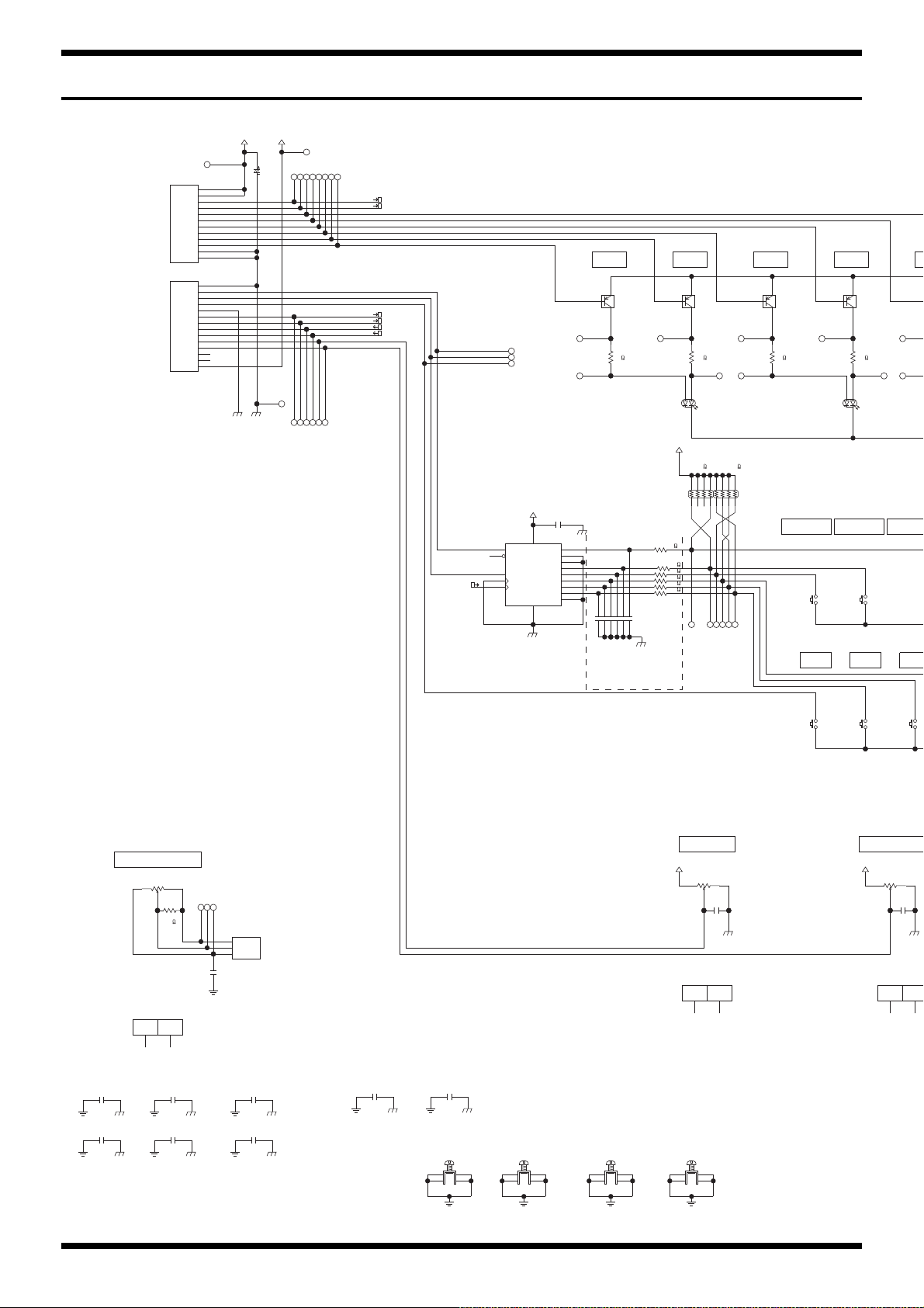
Oct. 2016 KTN-50
D+3.3V_PANEL
DG-REF_PADG-REF_PANEL
D+3.3V_PANEL
FG_PANEL_1 FG_PANEL_1 FG_PANEL_1 FG_PANEL_1
FG_PANEL_1
FG_PANEL_1
DG_PANEL
FG_PANEL_1
FG_PANEL_1FG_PANEL_1
FG_PANEL_1
DG_PANEL DG-REF_PANEL
DG_PANELDG_PANEL
DG_PANEL
FG_PANEL_1
LED-CLK
DG_PANEL
LED+3.3V_PANEL
LED+3.3V_PANEL
LED+3.3V_PANEL
LED-DATA
LED-CLK
SCAN-A
XCOM
YCOM
SCAN-B
D+3.3V_PANEL
DG-REF_PANEL DG_PANEL
DG_PANEL
FG_PANEL_2
DG_PANEL
FG_PANEL_3
DG_PANEL
DG_PANEL
DTA114EUAT106 (PB FREE)
Q502
1
3
2
DTA114EUAT106 (PB FREE)
Q503
1
32
DTA114EUAT106 (PB FREE)
Q504
1
32
1
DTA114EUAT106 (PB FREE)
Q505
1
32
S
S
1
12
SW501
SKQKABD010
12V
12
SW505
SKQKABD010
12V
12
SW500
SKQKABD010
12V
12
SW504
SKQKABD010
12V
1
2
RA500
10k
EXB28V103JX
1
8
8
6
54
3
2
7
RA501
10k
EXB28V103JX
18
8
6
54
3
27
5.5V
74VHC165FT
IC502
6
H
5
G
4
F
E
3
14
D
13
C
1
S/_L
7
_QH
9
QH
15
CK-INH
2
CK B
12
VCC
16
GND
8
10
SI
A
11
LED512
L-3WEGW
A(RED)
1
A(GRN)
3
K
2
LED513
L-3WEGW
A(RED)
1
A(GRN)
3
K
2
TER501
M1698
1
1
2
233
4
4
TER502
M1698
1
1
2
233
4
4
TER503
M1698
1
1
2
233
4
4
TER500
M1698
1
1
2
233
4
4
0.01uF
C511
UnPop
0.01uF
C510
UnPop
25V0.1uF
C516
25V0.1uF
C517
25V0.1uF
C515
25V0.1uF
C514
25V0.1uF
C518
25V0.1uF
C519
C521 0.1uF
25V
0.1uF
C520
UnPop
68
R513
1608
68
R511
1608
120
R514
1608
120
R512
1608
15k
R519
UnPop
1608
RD901F-40E1-15F-1B20K-00DN6
VR509
10
RD901F-40E1-15F-1B20K-00DN6
VR509
20
C500
10uF
25V
TP518
TP525
TP524
TP509
TP526
TP510
TP503
TP523 TP504
TP522
TP521
TP511
TP500
TP527
TP502
TP501
TP531
TP505
TP520
TP519
TP506
TP512 TP513 TP514 TP515 TP516
TP528 TP529 TP530 TP532 TP533
TP535
TP536
TP537
TP538
TP507
TP540
TP508
TP539
CN500
WIRING 1007#28 12X130-PHR-SAN-R(AP068 W5
1
1
2
2
3
3
4
4
5
5
6
6
8
8
9
9
10
10
11
11
12
12
7
7
CN501
WIRING 1007#28 14X120-PHR-SAN-F(AP068 W6
1
1
2
2
3
3
4
4
5
5
6
6
8
8
9
9
10
10
11
11
12
12
13
13
14
14
7
7
AP068 WIRING W3 (2547#28)
CN502
5100051869
1
2
3
VR509
RD901F-40E1-15F-1B20K-00DN6
13
2
VR510
RD901F-40-15F-B10K-05D60A
13
2
RD901F-40-15F-B10K-05D60A
VR510
10
RD901F-40-15F-B10K-05D60A
VR510
20
RD901F-40-125F-B1
VR511
10
RD901F-40-125F-B1
VR511
20
VR511
RD901F-40-125F-B10
13
2
50V
1000pF
C522
50V
1000pF
C523
50V
1000pF
C524
50V
1000pF
C525
50V
1000pF
C526
50V
1000pF
C527
1k
R500
1k
R501
1k
R502
1k
R503
1k
R504
1k
R507
25V0.1uF
C528
25V0.1uF
C529
MEMORY
FX1
MEMORY2
TAP
MASTER(ANALOG)
FX2
MEMORY1
TYPE POWER CONTR
FX3 R FFX2 RFX2 GFX3 G
[7A]
[7A]
[7F]
[7F]
[8F]
[8F]
4Click VR
to MAIN BOARD
CN1
[3A]
LED-FX1-RED
LED-FX3-RED
LED-CLK
SW-SXL
SW-DI1
D+3.3V
LED+3.3V
SW-TAP
DG
YCOM
ENC-A
ENC-B
XCOM
VR-TYPE-PRES
VR-PWR-CTL
DG
DG
SCAN-A
SCAN-B
LED+3.3V
LED-FX1-GREEN
LED-FX2-RED
LED-FX3-GREEN
LED-FX2-GREEN
DG
LED-DATA
to MAIN BOARD
CN3
Circuit Diagram (Panel Board)
fig.d-KTN-50-panel.eps@L
34
Page 35
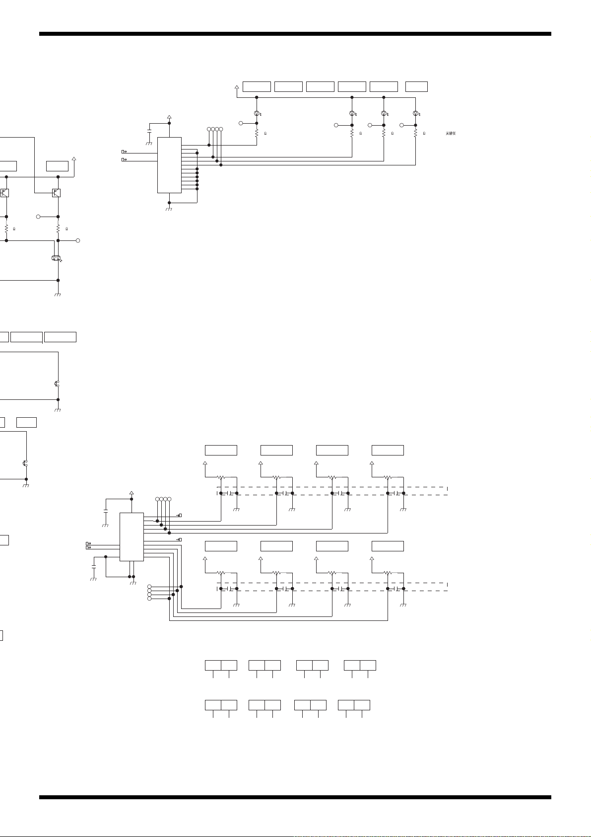
Oct. 2016 KTN-50
DG_PANEL
NEL
D+3.3V_PANEL
D+3.3V_PANEL
DG-REF_PANEL
D+3.3V_PANEL D+3.3V_PANEL
DG-REF_PANEL DG-REF_PANEL
DG-REF_PANELDG-REF_PANELDG-REF_PANEL
DG-REF_PANEL
D+3.3V_PANEL D+3.3V_PANEL D+3.3V_PANEL
SCAN-A
XCOM
YCOM
SCAN-B
DG-REF_PANEL
D+3.3V_PANEL
LED+3.3V_PANEL
LED-CLK
LED-DATA
DG_PANEL
LED+3.3V_PANEL
DG_PANEL
DG-REF_PANEL
D+3.3V_PANEL
DG_PANEL
LED+3.3V_PANEL
DG_PANEL
DG-REF_PANEL
DG_PANEL
DTA114EUAT106 (PB FREE)
Q500
1
3
2
DTA114EUAT106 (PB FREE)
Q501
3
2
SW503
SKQKABD010
12V
12
W502
KQKABD010
2V
SW508
SKQKABD010
12V
12
BU2090FS-E2
IC501
2
DATA
3
CLOCK
1
VSS
4
Q0
5
Q1
6
Q2
7
Q3
8
Q4
9
Q5
10
Q6
11
Q7
12
Q8
13
Q9
14
Q10
15
Q11
16
VDD
LED511
L-3WEGW
A(RED)
1
A(GRN)
3
K
2
L-34ID
LED509
12
L-34ID
LED506
1
2
L-34ID
LED505
12
L-34ID
LED510
12
0.01uF
C501
0.01uF
C505
0.01uF
C503
0.01uF
C506
0.01uF
C504
0.01uF
C507
0.01uF
C502
0.01uF
C508
25V
0.1uF
C513
25V
0.1uF
C512
5.5V
TC74VHC4052AFK
IC500
9
B
10
A
2
2Y
14
1X
2X
15
16
VCC
3
YCOM
7
GND
1Y
5
3Y
4
INH
6
1
0Y
XCOM
13
11
3X
0X
12
GND
8
68
R515
1608
120
R516
1608
220
R505
1608
220
R509
1608
220
R510
1608
220
R506
1608
20
RD901F-40E1-15F-0B10K-00D86A
VR503
10
20
RD901F-40E1-15F-0B10K-00D86A
VR504
10
20
RD901F-40E1-15F-0B10K-00D86A
VR506
10
20
RD901F-40E1-15F-0B10K-00D86A
VR507
10
20
20
RD901F-40E1-15F-0B10K-00D86A
VR505
10
RD901F-40E1-15F-0B10K-00D86A
VR502
10
VR501
RD901F-40E1-15F-0B10K-00D86A
13
2
VR505
RD901F-40E1-15F-0B10K-00D86A
13
2
VR506
RD901F-40E1-15F-0B10K-00D86A
13
2
VR502
RD901F-40E1-15F-0B10K-00D86A
13
2
VR504
RD901F-40E1-15F-0B10K-00D86A
13
2
VR503
RD901F-40E1-15F-0B10K-00D86A
13
2
VR507
RD901F-40E1-15F-0B10K-00D86A
13
2
TP517
TP534
TP541
TP542 TP543 TP544
TP545
TP546
TP547
TP548
TP549
TP550
TP551
TP552
TP553
TP554
TP555
TP556
25V
0.1uF
C509
VR500
RD901F-40E1-15F-0B10K-00D86A
13
2
RD901F-40E1-15F-0B10K-00D86A
VR500
10
20
RD901F-40E1-15F-0B10K-00D86A
VR501
10
20
K-04D60A
MEMORY4Y3 MANUAL
FX3
OL
FX1
VOLUME
FX3TREBLE
MIDDLEBASS
FX2
GAIN
MANUAL MEMORY1 TAPMEMORY3 MEMORY2MEMORY4
FX1 RX1 G
[3A]
[3A]
[3B]
[3B]
[3B]
[3B]
RED:Vf=2.0V(typ)
RED:Vf=2.0(typ)
I=10.83mA
GREEN:Vf=2.2(typ)
I=16.18mA
I=6mA
CUBE-*GX
With Keytop
With Keytop
unpop->0.01uF
unpop->0.01uF
fig.d-KTN-50-panel.eps@R
35
Page 36

Oct. 2016 KTN-50
Circuit Diagram (Amp Board)
fig.d-KTN-50-amp.eps
to MAIN BOARD
CN4
12.SENSOR
11.REF-GND
10.AG
9.C-FBK
8.AG
7.SIG-MAIN
6.MUTE-AMP
5.+PVCC
4.PG-AMP
3.PG-AMP
2.-PVCC
1.SP-OUT
CN700
5100051879
+PVCC_AMP
TP704
TP703
REF-GND_AMP
12
12
11
11
10
10
9
9
8
8
7
7
6
6
5
5
4
4
3
3
2
KTN-100 WIRING W10 (1430#24/1626#26)
2
1
1
TP702
TP701
TP700
-PVCC_AMP
PG_AMP
AG_AMP
TP705
TP706
TP707
TP708
TP709
SP-OUT
[4C]
560->470
1/16->1/10W 1/16->1/10W
R703
470
AG_AMP
SPOUT-MONITOR
[2D]
TP711
0
R707
1
1608
R700
330
1608
22k
AG_AMP
D700 1SS387
TP712
C710
100pF
50V
unpop->mount
R701
47k
1608
R702
22k
1608
1608
C708
47uF
63V
[105
C709
220pF
100V
1608
UnPop
R705
22k
TP713
AG_AMP
AG_AMP
AG_AMP
TP710
]
AG_AMP
2
3
4
10
9
C700
10uF
16V
2012
C701
0.1uF
50V
1608
TP714
10uF/16(2012)->0.1uF(1608)
+PVCC_AMP
C703
0.1uF
100V
3216
ININ+
SGND
MUTE
STBY
C702
0.1uF
100V
C704-->R708
AG_AMP
R704
22k
7
+VS
STBY-GND
1
AG_AMP
-PVCC_AMP
R708
0
HS_GND_1
1608
330uF
[105
11
13
+PWVS
BUFFER
-PWVS
-VS
15
8
C706
63V
]
Radial
PG_AMP
OUT
LOADER
BOOTS
CLIP_DET
IC700
TDA7293V
50V
C707
330uF
63V
[105
Radial
PG_AMP
PG_AMPAG_AMP
]
C711
0.1uF
1608
14
12
6
5
50V
HS_GND_2
C705
22uF
TP715
50V
[105 ]
SP-OUT
TP716
[2C]
SPOUT-MONITOR
[2B]
2
2
R706
1
1
NCU18WF104J60RB
REF-GND_AMP
KTN-50 POWER IC HOLDER
MK700
MK700
10
20
HS_GND_1
HS_GND_2
36
Page 37

Oct. 2016 KTN-50
Circuit Diagram (Jack Board)
fig.d-KTN-50-jack.eps
AUX IN
TP602
7
6
2
3
4
5
1
JK600
HSJ2000-01-010
C620
0.1uF
25V
FG_JK
AG-AUX_JK
to MAIN BOARD
CN6
1.DETECT-PHONES
2.PHG
3.SIG-PHONES
4.SIG-AUX-R
5.SIG-AUX-L
6.AG-AUX
7.AUX-MUTE
8.AG
9.SIG-LINEOUT
10.DETECT-RTN
11.AG-RTN
12.SIG-RETURN
13.AG
14.SIG-SEND
15.DETECT-SPK
AP067
5100051873
AP067 WIRING W7 (1007#28/2547#28)
1
1
2
2
3
3
4
4
5
5
6
6
7
7
CN602
AG-AUX_JK PHG_JK
TP603
TP609
0ohm
L600
0
1608
L601
0
1608
R602
100
1608
TP610
TP611
R600
220
1608
R601
220
1608
C601
220pF
50V
AG-AUX_JK
TP604
TP605
TP606
TP600
TP601
TP612
TP607
TP608
TP613
C600
220pF
50V
AG-AUX_JK
(4/21)
10uF-->1uF
C602
1uF
50V
C603
1uF
50V
DETECT-PHONES
R613
120
0.5W
3225
R614
120
0.5W
3225
1500pF
1
2
C613
50V
TER602
M1698
1
233
FG_JK
TP614
TP615
C615
1500pF
50V
DETECT-PHONES
4
Phones
L605
BLM18BD601SN1D
1608
L606
BLM18BD601SN1D
1608
C609
220pF
50V
unpop->220pF
FG_JK
C605
0.1uF
25V
C604
0.1uF
4
25V
C624
0.1uF
25V
PHG_JK AG-AUX_JK
TP616
C610
UnPop
FG_JK FG_JK
R608
100
1608
TP617
C622
UnPop
TP618
PHG_JK
PHONES
3T
4TS
RS 5
R2
6SS
1S
PJ-644C-EP
C618
0.1uF
25V
JK604
FG_JKFG_JK FG_JK
37
Page 38

Oct. 2016 KTN-50
FH900
FC-201
1
FH901
FC-201
1
SIN-21T-1.8
CN901
UnPop
SIN-21T-1.8
CN902
UnPop
SIN-21T-1.8
CN903
UnPop
B2P3S-VH (LF)(SN) 7A/250V
CN904
1
3
FS900
TP900
TP901
TP902
TER900
M1698
1
1
2
233
4
4
TER902
M1698
1
1
2
233
4
4
TER901
M1698
1
1
2
233
4
4
275V0.22uF
C900
MP10275K224D0150000
(HOT)
(COM)
(NC)
Radial
to POWER SW to TRANS
F900
100/117 : 1.25A
220/230/240 : 630mA
Circuit Diagram (Input Board)
fig.d-KTN-50-input.eps
GUITAR INPUT
2.2k->10kohm->15kohm
R400
15k
TP406
1
2
1608
DETECT-INPUT
TER400
M1698
1
233
FG_INPUT
33
44
66
JK400
PJ-644C-04-EP
11
AG_INPUT
-AVCC_INPUT
TP407
C405
10pF
50V
AG_INPUT
4
4
C410
Film
C426
2.2uF
50V
UnPop
+AVCC_INPUT
D400
1SS362FV
1
50V0.1uF
AG_INPUT
2
3
R401
1M
1608
0.012uF->0.018uF
+AVCC_INPUT
C416
0.1uF
25V
AG_INPUT
3
Q400
12
2SK880-GR
AG_INPUT
TP412
R404
6.8k
0.5%
C417
0.1uF
25V
AG_INPUT
-AVCC_INPUT
0.1uF
0.1uF
0.018uF
TP408
C423
10uF
25V
C418
10uF
25V
C406
25V
C402
25V
C403
50V
1608
1.5k->820ohm
R405
820
TP409
0.5%
1608
R410
15k
0.5%
1608
R420
0
1608
UnPop
C400
UnPop
1608
R408
100
1608
TP413
R414
22k
1608
AG_INPUT
AG_INPUT
C419
390pF
150pF->390pF
50V
TP410
1608
R416
0.5%
4.7k
1608
10k->4.7kohm
2
1
3
IC400
NJM4580M(TE2)
TP414
C404
150pF
50V
1608
+AVCC_INPUT
C424
0.1uF
25V
C425
0.1uF
25V
-AVCC_INPUT
10k
TP415
C422
47uF
16V
AG_INPUT
UnPop
R417
100
1608
47k
22k->47kohm
8
VDD
IC400
NJM4580M(TE2)
4
VEE
TP416
R413
0.5%
C401
1608
R418
1608
AG_INPUT
C421
15pF
50V
R419
47k
0.5%
22k->47kohm
6
5
NJM4580M(TE2)
TP417
C420
150pF
50V
1608
AG_INPUT
7
IC400
+AVCC_INPUT
C412
C414
330uF
330uF
16V
AG_INPUT
DETECT-INPUT
TP402
R421
150
-AVCC_INPUT
16V
AG_INPUT
TP403
TP404
TP405
CN4
to MAIN BOARD
6
5
4
3
2
1
CN400
AG_INPUT
6.AG
5.SIG-INPUT2
4.SIG-INPUT1
3.+AVCC
2.-AVCC
1.DETECT-INPUT
C407
220pF
50V
6
5
4
3
2
1
TP401
AP068 WIRING W4 (1007#28/2547#28)
TP400
R422
R402
150
100
1608
AG_INPUTFG_INPUT
Circuit Diagram (Fuse Board)
fig.d-KTN-50-fuse.eps
38
 Loading...