

Page 1
201a
Before using this unit, carefully read the sections entitled: “USING THE UNIT SAFELY”
and “IMPORTANT NOTES” (p. 2; p. 4). These sections provide important information
concerning the proper operation of the unit. Additionally, in order to feel assured that
you have gained a good grasp of every feature provided by your new unit, Owner’s
manual should be read in its entirety. The manual should be saved and kept on hand as
a convenient reference.
Conventions Used in This Manual
Operating buttons are enclosed by square brackets [ ]; e.g., [REC].
Reference pages are indicated by (p. **).
The following symbols are used.
This indicates an important note; be sure to read it.
This indicates a memo regarding the setting or function; read it as desired.
This indicates a useful hint for operation; read it as necessary.
This indicates information for your reference; read it as necessary.
This indicates an explanation of a term; read it as necessary.
Owner’s Manual
Thank you, and congratulations on your choice of the Roland JUNO-G.
985
* The explanations in this manual include illustrations that depict what should typically be shown by the display. Note, however, that your
unit may incorporate a newer, enhanced version of the system (e.g., includes newer sounds), so what you actually see in the display may
not always match what appears in the manual.
202
Copyright © 2006 ROLAND CORPORATION
All rights reserved. No part of this publication may be reproduced in any form without the
written permission of ROLAND CORPORATION.
Page 2
For the U.K.
IMPORTANT: THE WIRES IN THIS MAINS LEAD ARE COLOURED IN ACCORDANCE WITH THE FOLLOWING CODE.
As the colours of the wires in the mains lead of this apparatus may not correspond with the coloured markings identifying
the terminals in your plug, proceed as follows:
The wire which is coloured BLUE must be connected to the terminal which is marked with the letter N or coloured BLACK.
The wire which is coloured BROWN must be connected to the terminal which is marked with the letter L or coloured RED.
Under no circumstances must either of the above wires be connected to the earth terminal of a three pin plug.
USING THE UNIT SAFELY
BLUE:
BROWN:
NEUTRAL
LIVE
Used for instructions intended to alert
the user to the risk of death or severe
injury should the unit be used
improperly.
Used for instructions intended to alert
the user to the risk of injury or material
damage should the unit be used
improperly.
* Material damage refers to damage or
other adverse effects caused with
respect to the home and all its
furnishings, as well to domestic
animals or pets.
The symbol alerts the user to important instructions
or warnings.The specific meaning of the symbol is
determined by the design contained within the
triangle. In the case of the symbol at left, it is used for
general cautions, warnings, or alerts to danger.
The symbol alerts the user to items that must never
be carried out (are forbidden). The specific thing that
must not be done is indicated by the design contained
within the circle. In the case of the symbol at left, it
means that the unit must never be disassembled.
The ● symbol alerts the user to things that must be
carried out. The specific thing that must be done is
indicated by the design contained within the circle. In
the case of the symbol at left, it means that the powercord plug must be unplugged from the outlet.
001
• Before using this unit, make sure to read the instructions below, and the Owner’s Manual.
..........................................................................................................
002d
• Do not open or perform any internal modifications on
the unit or its AC adaptor. (The only exception would be
where this manual provides specific instructions which
should be followed in order to put in place userinstallable options; see p. 174, p. 176.)
..........................................................................................................
003
• Do not attempt to repair the unit, or replace parts within it
(except when this manual provides specific instructions
directing you to do so). Refer all servicing to your retailer,
the nearest Roland Service Center, or an authorized
Roland distributor, as listed on the “Information” page.
..........................................................................................................
004
• Never use or store the unit in places that are:
• Subject to temperature extremes (e.g., direct sunlight
in an enclosed vehicle, near a heating duct, on top of
heat-generating equipment); or are
• Damp (e.g., baths, washrooms, on wet floors); or are
• Humid; or are
• Exposed to rain; or are
• Dusty; or are
• Subject to high levels of vibration.
..........................................................................................................
005
• This unit should be used only with a stand (KS-12) that
is recommended by Roland.
006
• When using the unit with a stand (KS-12) recommended
by Roland, the rack or stand must be carefully placed so it
is level and sure to remain stable. If not using a rack or
stand, you still need to make sure that any location you
choose for placing the unit provides a level surface that
will properly support the unit, and keep it from wobbling.
..........................................................................................................
008c
• Be sure to use only the AC adaptor supplied with the
unit. Also, make sure the line voltage at the installation
matches the input voltage specified on the AC adaptor’s
body. Other AC adaptors may use a different polarity,
or be designed for a different voltage, so their use could
result in damage, malfunction, or electric shock.
..........................................................................................................
008e
• Use only the attached power-supply cord. Also, the
supplied power cord must not be used with any other
device.
..........................................................................................................
009
• Do not excessively twist or bend the power cord, nor
place heavy objects on it. Doing so can damage the cord,
producing severed elements and short circuits.
Damaged cords are fire and shock hazards!
..........................................................................................................
010
• This unit, either alone or in combination with an
amplifier and headphones or speakers, may be capable
of producing sound levels that could cause permanent
hearing loss. Do not operate for a long period of time at
a high volume level, or at a level that is uncomfortable.
If you experience any hearing loss or ringing in the ears,
you should immediately stop using the unit, and consult
an audiologist.
2
Page 3
011
• Do not allow any objects (e.g., flammable material,
coins, pins); or liquids of any kind (water, soft drinks,
etc.) to penetrate the unit. When you install the Wave
Expansion Board (SRX series) or memory (DIMM),
please be careful particularly.
..........................................................................................................
012b
• Immediately turn the power off, remove the AC adaptor
from the outlet, and request servicing by your retailer,
the nearest Roland Service Center, or an authorized
Roland distributor, as listed on the “Information” page
when:
• The AC adaptor, the power-supply cord, or the plug
has been damaged; or
• If smoke or unusual odor occurs
• Objects have fallen into, or liquid has been spilled
onto the unit; or
• The unit has been exposed to rain (or otherwise has
become wet); or
• The unit does not appear to operate normally or
exhibits a marked change in performance.
..........................................................................................................
013
• In households with small children, an adult should
provide supervision until the child is capable of
following all the rules essential for the safe operation of
the unit.
..........................................................................................................
014
• Protect the unit from strong impact.
(Do not drop it!)
..........................................................................................................
015
• Do not force the unit’s power-supply cord to share an
outlet with an unreasonable number of other devices. Be
especially careful when using extension cords—the total
power used by all devices you have connected to the
extension cord’s outlet must never exceed the power
rating (watts/amperes) for the extension cord. Excessive
loads can cause the insulation on the cord to heat up and
eventually melt through.
..........................................................................................................
016
• Before using the unit in a foreign country, consult with
your retailer, the nearest Roland Service Center, or an
authorized Roland distributor, as listed on the “Information” page.
..........................................................................................................
022b
• Always turn the unit off and unplug the AC adaptor
before attempting installation of the circuit board (SRX
series; p. 174, DIMM; p. 176).
..........................................................................................................
023
• DO NOT play a CD-ROM disc on a conventional audio
CD player. The resulting sound may be of a level that
could cause permanent hearing loss. Damage to
speakers or other system components may result.
101b
• The unit and the AC adaptor should be located so their
location or position does not interfere with their proper
ventilation.
..........................................................................................................
101c
• This (JUNO-G) for use only with Roland stand (KS-12).
Use with other stands is capable of resulting in instability
causing possible injury.
..........................................................................................................
102c
• Always grasp only the plug on the AC adaptor cord
when plugging into, or unplugging from, an outlet or
this unit.
..........................................................................................................
103b
• At regular intervals, you should unplug the AC adaptor
and clean it by using a dry cloth to wipe all dust and
other accumulations away from its prongs. Also,
disconnect the power plug from the power outlet
whenever the unit is to remain unused for an extended
period of time. Any accumulation of dust between the
power plug and the power outlet can result in poor
insulation and lead to fire.
..........................................................................................................
104
• Try to prevent cords and cables from becoming
entangled. Also, all cords and cables should be placed
so they are out of the reach of children.
..........................................................................................................
106
• Never climb on top of, nor place heavy objects on the
unit.
..........................................................................................................
107c
• Never handle the AC adaptor or its plugs with wet
hands when plugging into, or unplugging from, an
outlet or this unit.
..........................................................................................................
108b
• Before moving the unit, disconnect the AC adaptor and
all cords coming from external devices.
..........................................................................................................
109b
• Before cleaning the unit, turn off the power and unplug
the AC adaptor from the outlet (p. 15).
..........................................................................................................
110b
• Whenever you suspect the possibility of lightning in
your area, disconnect the AC adaptor from the outlet.
..........................................................................................................
115a
• Install only the specified circuit board(s) (SRX series,
DIMM). Remove only the specified screws (p. 174, p.
176).
..........................................................................................................
118a
• Should you remove the ground terminal screw or
screws that fasten the bottom cover or the PC card
protector, keep them in a safe place out of children’s
reach, so there is no chance of them being swallowed
accidentally.
3
Page 4

IMPORTANT NOTES
291a
In addition to the items listed under “USING THE UNIT SAFELY” on page 2–3, please read and observe the following:
Power Supply
301
• Do not connect this unit to same electrical outlet that is being
used by an electrical appliance that is controlled by an inverter
(such as a refrigerator, washing machine, microwave oven, or air
conditioner), or that contains a motor. Depending on the way in
which the electrical appliance is used, power supply noise may
cause this unit to malfunction or may produce audible noise. If it
is not practical to use a separate electrical outlet, connect a power
supply noise filter between this unit and the electrical outlet.
302
• The AC adaptor will begin to generate heat after long hours of
consecutive use. This is normal, and is not a cause for concern.
307
• Before connecting this unit to other devices, turn off the power to
all units. This will help prevent malfunctions and/or damage to
speakers or other devices.
Placement
351
• Using the unit near power amplifiers (or other equipment
containing large power transformers) may induce hum. To
alleviate the problem, change the orientation of this unit; or move
it farther away from the source of interference.
352a
• This device may interfere with radio and television reception. Do
not use this device in the vicinity of such receivers.
352b
• Noise may be produced if wireless communications devices, such
as cell phones, are operated in the vicinity of this unit. Such noise
could occur when receiving or initiating a call, or while
conversing. Should you experience such problems, you should
relocate such wireless devices so they are at a greater distance
from this unit, or switch them off.
354a
• Do not expose the unit to direct sunlight, place it near devices
that radiate heat, leave it inside an enclosed vehicle, or otherwise
subject it to temperature extremes. Excessive heat can deform or
discolor the unit.
355b
• When moved from one location to another where the temperature and/or humidity is very different, water droplets (condensation) may form inside the unit. Damage or malfunction may
result if you attempt to use the unit in this condition. Therefore,
before using the unit, you must allow it to stand for several
hours, until the condensation has completely evaporated.
358
• Do not allow objects to remain on top of the keyboard. This can
be the cause of malfunction, such as keys ceasing to produce
sound.
360
• Depending on the material and temperature of the surface on which
you place the unit, its rubber feet may discolor or mar the surface.
You can place a piece of felt or cloth under the rubber feet to
prevent this from happening. If you do so, please make sure that the
unit will not slip or move accidentally.
Maintenance
401a
• For everyday cleaning wipe the unit with a soft, dry cloth or one that
has been slightly dampened with water. To remove stubborn dirt,
use a cloth impregnated with a mild, non-abrasive detergent. Afterwards, be sure to wipe the unit thoroughly with a soft, dry cloth.
402
• Never use benzine, thinners, alcohol or solvents of any kind, to
avoid the possibility of discoloration and/or deformation.
Repairs and Data
452
• Please be aware that all data contained in the unit’s memory may
be lost when the unit is sent for repairs. Important data should
always be backed up on a memory card, or written down on
paper (when possible). During repairs, due care is taken to avoid
the loss of data. However, in certain cases (such as when circuitry
related to memory itself is out of order), we regret that it may not
be possible to restore the data, and Roland assumes no liability
concerning such loss of data.
Additional Precautions
551
• Please be aware that the contents of memory can be irretrievably
lost as a result of a malfunction, or the improper operation of the
unit. To protect yourself against the risk of loosing important
data, we recommend that you periodically save a backup copy of
important data you have stored in the unit’s memory on a
memory card.
552
• Unfortunately, it may be impossible to restore the contents of
data that was stored on a memory card or unit’s memory once it
has been lost. Roland Corporation assumes no liability
concerning such loss of data.
553
• Use a reasonable amount of care when using the unit’s buttons,
sliders, or other controls; and when using its jacks and
connectors. Rough handling can lead to malfunctions.
554
• Never strike or apply strong pressure to the display.
556
• When connecting / disconnecting all cables, grasp the connector
itself—never pull on the cable. This way you will avoid causing
shorts, or damage to the cable’s internal elements.
558a
• To avoid disturbing your neighbors, try to keep the unit’s volume
at reasonable levels. You may prefer to use headphones, so you
do not need to be concerned about those around you (especially
when it is late at night).
559a
• When you need to transport the unit, package it in the box
(including padding) that it came in, if possible. Otherwise, you
will need to use equivalent packaging materials.
561
• Use only the specified expression pedal (EV-5; sold separately).
By connecting any other expression pedals, you risk causing
malfunction and/or damage to the unit.
562
• Use a cable from Roland to make the connection. If using some other
make of connection cable, please note the following precautions.
• Some connection cables contain resistors. Do not use cables
that incorporate resistors for connecting to this unit. The use
of such cables can cause the sound level to be extremely low,
or impossible to hear. For information on cable specifications,
contact the manufacturer of the cable.
566b
• The sensitivity of the D Beam controller will change depending
on the amount of light in the vicinity of the unit. If it does not
function as you expect, adjust the sensitivity as appropriate for
the brightness of your location.
4
Page 5
IMPORTANT NOTES
Before Using Cards
Using Memory Cards (p. 178)
704
• Carefully insert the memory card all the way in—until it is firmly
in place.
705
• Never touch the terminals of the memory card. Also, avoid
getting the terminals dirty.
707
• This unit’s PC card slot accepts CompactFlash memory cards.
Microdrive storage media are not compatible.
708
• CompactFlash and SmartMedia (3.3 V) are constructed using
precision components; handle the cards carefully, paying
particular note to the following.
• To prevent damage to the cards from static electricity, be sure
to discharge any static electricity from your own body before
handling the cards.
• Do not touch or allow metal to come into contact with the
contact portion of the cards.
• Do not bend, drop, or subject cards to strong shock or
vibration.
• Do not keep cards in direct sunlight, in closed vehicles, or
other such locations (storage temperature: -25 to 85˚ C).
• Do not allow cards to become wet.
• Do not disassemble or modify the cards.
220
* All product names mentioned in this document are trade-
marks or registered trademarks of their respective owners.
230
* SmartMedia is a trademark of Toshiba Corp.
234
* CompactFlash and are trademarks of SanDisk
Corporation and licensed by CompactFlash association.
235
* Roland Corporation is an authorized licensee of the
CompactFlash™ and CF logo ( ) trademarks.
Handling CD-ROMs
801
• Avoid touching or scratching the shiny underside (encoded
surface) of the disc. Damaged or dirty CD-ROM discs may not be
read properly. Keep your discs clean using a commercially
available CD cleaner.
Copyright
851
• Unauthorized recording, distribution, sale, lending, public
performance, broadcasting, or the like, in whole or in part, of a
work (musical composition, video, broadcast, public performance, or the like) whose copyright is held by a third party is
prohibited by law.
853
• Do not use this unit for purposes that could infringe on a
copyright held by a third party. We assume no responsibility
whatsoever with regard to any infringements of third-party
copyrights arising through your use of this unit.
5
Page 6

Contents
USING THE UNIT SAFELY......................................................................2
IMPORTANT NOTES ...............................................................................4
Main Features........................................................................................10
Panel Descriptions................................................................................11
Front Panel................................................................................................................................................. 11
Rear Panel.................................................................................................................................................. 13
Getting Ready........................................................................................14
Connections............................................................................................................................................... 14
Turning On/Off the Power..................................................................................................................... 15
Adjusting the Display Contrast (LCD Contrast).................................................................................. 15
Listening to the Demo Songs .................................................................................................................. 15
Various Performance Features............................................................16
Overview of the JUNO-G ......................................................................17
How the JUNO-G Is Organized ............................................................................................................. 17
About Memory.......................................................................................................................................... 19
About the Onboard Effects ..................................................................................................................... 20
About the Song Recorder ........................................................................................................................21
About Audio Track Recording ............................................................................................................... 22
Basic Operation of the JUNO-G...........................................................23
Switching the Sound Generator Mode .................................................................................................. 23
About the Function Buttons.................................................................................................................... 23
Moving the Cursor ................................................................................................................................... 24
Changing a Value ..................................................................................................................................... 24
Assigning a Name ....................................................................................................................................24
Playing in Patch Mode..........................................................................25
About the PATCH PLAY Screen............................................................................................................ 25
Selecting Patches in the Main Screen..................................................................................................... 26
Using the Category Group Buttons to Select Patches ......................................................................... 26
Selecting Patches from the List............................................................................................................... 27
Auditioning a Patch or Rhythm Set (Phrase Preview)........................................................................ 28
Transposing the Keyboard in Octave Units (Octave Shift) ................................................................ 28
Transposing the Keyboard in Semitone Steps (Transpose)................................................................ 29
Selecting the Tones That Will Sound (Tone On/Off).......................................................................... 29
Playing Percussion Instruments............................................................................................................. 29
Adjusting the Volume Balance between the Keyboard Performance and the Rhythm Pattern ... 29
Creating a Patch....................................................................................30
How to Make Patch Settings................................................................................................................... 30
Saving Patches You’ve Created (Write) ................................................................................................32
Functions of Patch Parameters ...............................................................................................................34
Creating a Rhythm Set .........................................................................49
How to Make Rhythm Set Settings........................................................................................................ 49
Saving Rhythm Sets You’ve Created (Write) .......................................................................................51
Functions of Rhythm Set Parameters .................................................................................................... 52
Playing in Performance Mode..............................................................58
Displaying PERFORM PLAY Screen..................................................................................................... 58
6
Page 7

Displaying PART MIXER Screen ...........................................................................................................58
Functions in the PERFORMANCE PLAY/MIXER Screen................................................................. 58
Selecting a Performance........................................................................................................................... 59
Using the PLAY Screen............................................................................................................................ 60
Combining and Playing Sounds Together (Layer).............................................................................. 60
Playing Different Sounds in Different Areas of the Keyboard (Split) ..............................................61
Using the MIXER Screen .........................................................................................................................61
Creating a Performance .......................................................................63
Adjusting the Parameters of Each Part ................................................................................................. 63
Changing the Settings of the Patch Assigned to a Part....................................................................... 63
Saving a Performance You’ve Created (Write) .................................................................................... 63
Functions of Parameters of Each Part (Performance Parameters)..................................................... 64
MIDI Settings ............................................................................................................................................67
Settings for the D Beam and the Controller.......................................................................................... 68
Modifying the Sound in Real Time ......................................................69
D Beam Controller.................................................................................................................................... 69
Control Pedal ............................................................................................................................................ 72
Playing Arpeggios ................................................................................73
About Arpeggio........................................................................................................................................ 73
Playing Arpeggios.................................................................................................................................... 73
Arpeggio Settings ..................................................................................................................................... 74
Creating an Arpeggio Style (Arpeggio Style Edit) ..............................................................................75
Saving the Styles You Have Created (Write)........................................................................................ 76
Using the Chord Memory Function .....................................................77
About the Chord Memory Function...................................................................................................... 77
Performing with the Chord Memory Function.................................................................................... 77
Creating Your Own Chord Forms .........................................................................................................78
Saving the Chord Forms You Have Created (Write) ..........................................................................78
Playing Rhythms...................................................................................79
About Rhythm Patterns........................................................................................................................... 79
Using Rhythm Groups............................................................................................................................. 79
Playing Rhythm ........................................................................................................................................ 79
Rhythm Pattern Settings.......................................................................................................................... 80
Creating a Rhythm Pattern (Rhythm Pattern Edit) ............................................................................. 81
Saving the Rhythm Pattern You Have Created (Write)...................................................................... 81
Creating a Rhythm Group (Rhythm Group Edit)................................................................................ 82
Saving the Rhythm Group You Have Created (Write)....................................................................... 82
Creating a List of Frequently Used Patches, Performances, or Songs
(Live Setting) .........................................................................................83
Recalling Sounds ...................................................................................................................................... 83
Registering a Sound .................................................................................................................................83
Registering a Song.................................................................................................................................... 83
Removing a Registration ......................................................................................................................... 83
Removing all Registrations from a Bank............................................................................................... 83
Playing Back a Song.............................................................................84
Loading and Playing a Song (Load Play).............................................................................................. 84
Playing MIDI Tracks Immediately (Quick Play) ................................................................................. 84
Various Playback Methods .....................................................................................................................85
Recording a Song (MIDI Track)............................................................87
Before You Record a New MIDI Track.................................................................................................. 87
Recording Your Performance as You Play It (Realtime Recording) .................................................88
Inputting Data One Step at a Time (Step Recording).......................................................................... 92
7
Page 8

Editing a Song (MIDI Track) .................................................................94
Loading the Song You Want to Edit ...................................................................................................... 94
Editing Sequencer Data Over the Specified Range (Track Edit) ....................................................... 97
Editing Individual Items of Sequencer Data (Micro Edit).................................................................. 99
Assigning a Name to a Song (Song Name)......................................................................................... 103
Recording a Song (Audio Track) .......................................................104
Before You Record Audio via the AUDIO INPUT Jacks.................................................................. 104
Recording an Audio Track (SOLO/RE-SAMPLING) ....................................................................... 105
Combining Multiple Audio Tracks into One Track (AUDIO MERGE) ......................................... 106
Editing a Song (Audio Track).............................................................108
Items in the AUDIO TRACK Screen.................................................................................................... 108
Editing Audio Tracks (AUDIO TRACK Screen)................................................................................ 108
Items in the AUDIO MIXER Screen..................................................................................................... 111
Controlling the Audio Tracks (AUDIO MIXER screen) ...................................................................111
Saving/Loading a Song (Save/Load).................................................113
Saving a Song (Save) .............................................................................................................................. 113
Saving a Song as an SMF File (Save as SMF)...................................................................................... 114
Loading a Song (Load)........................................................................................................................... 115
Editing a Audio Phrase (Sample) ......................................................117
Sample List .............................................................................................................................................. 117
Sample Edit ............................................................................................................................................. 119
Saving a Sample (Write) ........................................................................................................................ 124
Adding Effects.....................................................................................125
Turning Effects On and Off................................................................................................................... 125
Making Effect Settings ........................................................................................................................... 125
Applying Effects in Patch Mode .......................................................................................................... 126
Applying Effects in Performance Mode.............................................................................................. 127
Making Multi-Effects Settings (MFX1–3)............................................................................................ 129
Making Multi-Effects Settings (MFX Control) ...................................................................................129
Specifying the Multi-Effects Structure (MFX Structure)................................................................... 130
Multi-Effects Parameters ....................................................................................................................... 131
Making Chorus Settings ........................................................................................................................ 154
Making Reverb Settings......................................................................................................................... 155
Mastering Effect...................................................................................................................................... 156
Settings Common to All Modes (System Function) ........................157
How to Make System Function Settings ............................................................................................. 157
Saving the System Settings (System Write) ........................................................................................ 157
System Information................................................................................................................................ 157
Functions of System Parameters ..........................................................................................................158
Data Management Functions/
Reset to Factory Settings (Factory Reset) .......................................164
Backing Up User Data (User Backup) .................................................................................................164
Restoring User Data that You Backed Up (User Restore) ................................................................ 164
Factory Reset ........................................................................................................................................... 164
Initializing a Memory Card (Card Format) ........................................................................................ 164
File-Related Functions (File Utility)...................................................165
Basic Procedure....................................................................................................................................... 165
Copying a File (Copy)............................................................................................................................ 166
Deleting a File (Delete) .......................................................................................................................... 166
Moving a File (Move)............................................................................................................................. 166
Initializing a Memory Card (Card Format) ........................................................................................ 166
8
Page 9

Connecting to Your Computer via USB ............................................167
About USB Functions............................................................................................................................. 167
Selecting the USB Operating Mode ..................................................................................................... 167
Transferring Files to or from Your Computer (Storage Mode) ....................................................... 167
Exchanging MIDI Messages with Your Computer (MIDI Mode)................................................... 169
Using JUNO-G Editor/Librarian .........................................................170
Installing JUNO-G Editor/Librarian into Your Computer.............................................................. 170
Making Connections .............................................................................................................................. 170
About PC Mode ...................................................................................................................................... 170
JUNO-G Editor/Librarian System Requirements ............................................................................. 170
About V-LINK.......................................................................................172
What is V-LINK? .................................................................................................................................... 172
Connection Example .............................................................................................................................. 172
Turning the V-LINK ON/OFF ............................................................................................................. 172
V-LINK Settings (V-LINK SETUP) ......................................................................................................173
Installing the Wave Expansion Board...............................................174
Cautions When Installing a Wave Expansion Board ........................................................................174
How to Install a Wave Expansion Board ............................................................................................ 174
Checking the Installed Wave Expansion Board................................................................................. 175
Expanding the Memory ......................................................................176
Precautions for Expanding Memory ................................................................................................... 176
How to Expand the Memory ................................................................................................................ 176
Checking that memory is installed correctly...................................................................................... 177
Using a Memory Card .........................................................................178
Before Using the Memory Card ........................................................................................................... 178
Writing data to the card......................................................................................................................... 178
Installing the PC Card Protector ..........................................................................................................178
Troubleshooting..................................................................................179
Error Messages ...................................................................................186
Performance List.................................................................................187
Patch List.............................................................................................188
Rhythm Set List...................................................................................193
Waveform List .....................................................................................202
Arpeggio Style List .............................................................................205
Rhythm Group List .............................................................................206
Rhythm Pattern List............................................................................207
About MIDI ...........................................................................................209
MIDI Implementation...........................................................................210
MIDI Implementation Chart ................................................................241
Specifications......................................................................................243
Index.....................................................................................................244
9
Page 10
Main Features
The JUNO-G is a high-quality synthesizer with professional sounds
and playability. It features the latest sound generator, a variety of
effects, and a song recorder with audio tracks, all combined into an
easy-to-use instrument. The features listed below make the JUNO-G
a great choice for any style of music, in applications ranging from
stage performance to composition and arranging.
The latest sound engine with 128voice polyphony
The JUNO-G provides 128 voices of polyphony—the standard for
the new era. You can layer complex sounds and enjoy multitrack
recording using the song recorder.
Support for wave expansion boards
To supplement the numerous patches that use the carefully selected
high quality waves built into the JUNO-G, you can install one wave
expansion board to add more waveform data. Depending on your
needs and your favorite musical styles, you can choose one board
from the wide variety of professionally acclaimed Roland SRX series
boards now available.
Song recorder with audio tracks
The built-in song recorder provides four dedicated audio tracks
(stereo) in addition to the MIDI tracks (16 parts). This lets you create
songs that contain audio acquired from a performing vocalist or
guitarist in combination with the music produced by the internal
sound generator.
The MIDI track section provides a high-resolution 16-part (MIDI)
sequencer that’s designed with features like loop recording so that
you can record non-stop without interrupting your musical
imagination.
The audio track section contains 4 MB of memory as standard
(corresponding to approximately 23.5 seconds of stereo recording).
You can add DIMM memory (up to 512 MB) to expand the recording
capacity to a maximum of 51 minutes (stereo). In addition to audio
phrases you record on the JUNO-G, you can also import audio files
(in WAV or AIFF format) from your PC and use them as audio track
phrases.
Versatile sound control functionality
In addition to a D Beam controller, the JUNO-G provides a wide
range of controllers, such as the sound modify knobs and a hold
pedal jack that can detect half-damper operations. The JUNO-G
gives you complete control over your on-stage sound.
Plenty of external interfacing
The rear panel USB connector supports both file transfer and USBMIDI, and can be switched as desired. There’s also a PC card slot
that can accommodate SmartMedia or CompactFlash via a
commercially available adaptor. You can use a card to store as much
as 1 GB of data (when using CompactFlash).
JUNO-G Editor/Librarian is included
Dedicated editor/librarian software is included, letting you edit and
manage JUNO-G sounds from the large screen of your computer.
V-LINK functionality
V-LINK allows you to synchronize music and video, opening up
completely new performance possibilities.
If you use the JUNO-G in conjunction with a V-LINK compatible
video device (such as the Edirol motion dive .tokyo Performance
Package, DV-7PR, PR-50, or V-4), you’ll be able to control the images
using the same operations as when playing music on the JUNO-G.
General MIDI/GM2 compatibility
The JUNO-G is compatible with General MIDI/GM2, and is able to
play back music data that complies with the General MIDI/GM2
standard (General MIDI scores).
Live Setting function
The Live Setting function allows you to memorize settings and recall
them as your live set progresses, guaranteeing that your
performance will go smoothly.
Sample Patch function
This function lets you recall audio phrases from the audio tracks and
play them on the keyboard just like patches or rhythm sets.
Powerful effects including mastering
functionality
The JUNO-G provides three multi-effects processors (78 types), plus
independent chorus and reverb processors. There’s a mastering
effect, indispensable for adding the final touch to your production,
bringing your sound CD-master level impact and audio quality.
10
Page 11
Panel Descriptions
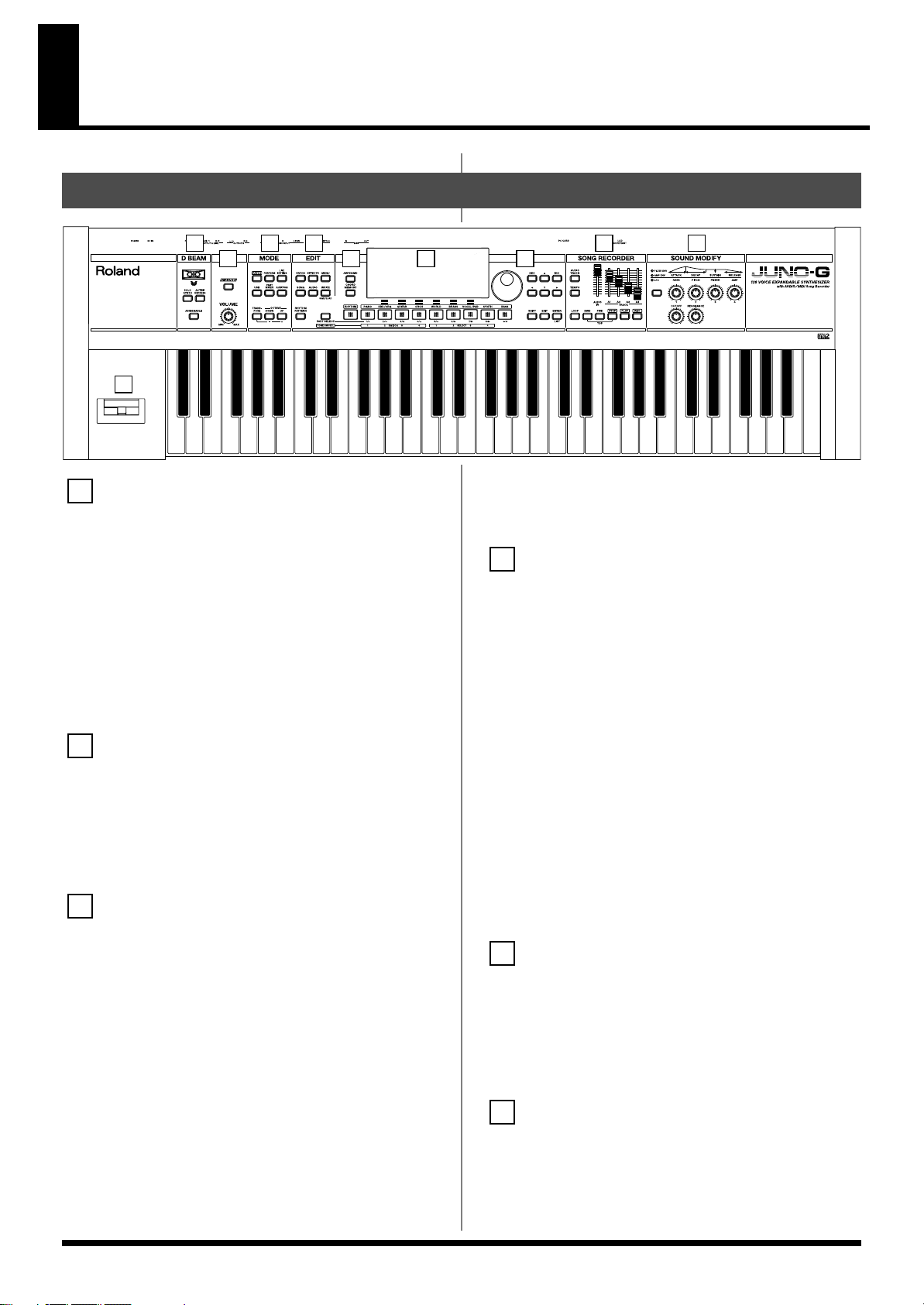
Front Panel
fig.Front
1
3 4
2
5 6 7
10
1
D BEAM
Switches D Beam function on/off. You can apply a variety of effects
to sounds simply by moving your hand (p. 69).
[SOLO SYNTH]
Play the JUNO-G as a monophonic synthesizer (p. 70).
[ACTIVE EXPRESS]
Play the JUNO-G as a active expression (p. 71).
[ASSIGNABLE]
You can assign a variety of parameters and functions to D Beam to
modify the sound in realtime (p. 71).
* Hold down [SHIFT] and press one of the corresponding buttons to
access the D BEAM setting screen.
2
VOLUME Knob
Adjusts the overall volume that is output from the rear panel
OUTPUT A (MIX) jacks and PHONES jack (p. 15).
[V-LINK]
Switches the V-LINK function on/off (p. 172).
Press this button to access the V-LINK setting screen.
3
MODE
[PATCH]
Enter Patch mode (p. 25).
[PERFORM]
View the Performance mode’s Play screen (p. 58).
[LIVE SETTING]
View the LIVE SETTING screen (p. 83).
[USB]
Accesses the USB function select screen (p. 167).
[PART MIXER]
View the Performance mode’s Mixer screen (p. 58).
[AUDITION]
Hold down this button to audition the currently selected sound (p. 28).
[TRANSPOSE]
By holding down [TRANSPOSE] and pressing [+] [-], you can raise
8 9
or lower the keyboard range in steps of a semitone (p. 29).
OCTAVE [UP] [DOWN]
Transposes the pitch of the keyboard in 1 octave units (p. 28).
4
EDIT
[PATCH]
Make patch-related settings (p. 30).
[EFFECTS]
Make effect-related settings (p. 125).
[MENU]
Opens the MENU. The contents of the menu will depend on the
current mode.
[SONG]
Press this button to edit the entire song or to edit MIDI tracks. Also,
this button is pressed to toggle between the Song Edit screen and the
Song List screen (p. 84, p. 87, p. 94).
[AUDIO]
This button accesses the Sample Edit screen. Also, this button is
pressed to toggle between the Sample Edit screen and the Sample
List screen (p. 117).
[WRITE]
Save edited settings into internal memory or a memory card (p. 32,
p. 51, p. 63, p. 76, p. 78, p. 124).
5
[ARPEGGIO]
Switches the ARPEGGIO on/off. The arpeggio setting screen will
appear when you turn this on (p. 73).
[CHORD MEMORY]
Switches the CHORD MEMORY on/off. The chord memory setting
screen will appear when you turn this on (p. 77).
6
Display
This displays information regarding the operation you are
performing.
11
Page 12
Panel Descriptions
[RHYTHM PATTERN]
This button accesses the Rhythm Pattern playback screen (p. 79).
[PART SELECT/TONE SW/SEL]
When you press this button so it’s lit, the category group buttons
will operate as part select, tone switch, or tone select buttons.
[RHYTHM]–[BASS]
These are the category group buttons (only in Patch mode).
Function Buttons
([F1 (KBD/ORG)]–[F6 (VOCAL/PAD)])
The row of six buttons below the display are used to carry out
various functions during editing and other tasks. The functions of
these buttons will depend on the screen that you’ve selected (p. 23).
7
VALUE Dial
This is used to modify values. If you hold down [SHIFT] as you turn
the VALUE dial, the value will change in greater increments (p. 24).
[DEC], [INC]
This is used to modify values. If you keep on holding down one
button while pressing the other, the value change accelerates. If you
press one of these buttons while holding down [SHIFT], the value
will change in bigger increments (p. 24).
[ ], [ ], [ ], [ ]
Moves the cursor location up/down/left/right (p. 24).
[SHIFT]
This button is used in conjunction with other buttons to execute
various functions.
[EXIT]
Return to the previous screen, or close the currently open window.
In some screens, this causes the currently executing function to be
aborted.
[ENTER]
Use this button to execute an operation.
[STOP]
Controls song recorder stop.
[PLAY]
Controls song recorder play.
* While stopped, you can hold down [SHIFT] and Press [
perform MIDI Update (p. 86).
PLAY
] to
[REC]
The display changes to the Recording Standby window (p. 88, p. 92,
p. 105). If you press this button while recording a MIDI track, the
Rehearsal function will be activated (p. 92).
9
SOUND MODIFY
Turn these knobs to adjust the sound in real time or to edit
parameter values.
Pressing the button located at the left of knobs 1–4 will change the
illumination status of the indicators located above the button, and
will change the function of knobs 1–4 (p. 30).
* In the performance mode, this button doesn’t function.
The CUTOFF knob and RESONANCE knob are dedicated to
controlling Cutoff Frequency and Resonance (p. 30).
10
Pitch Bend/Modulation Lever
This allows you to control pitch bend or apply vibrato (p. 16).
8
SONG RECORDER
[AUDIO TRACK]
This button accesses the Audio Track screen (p. 104, p. 108).
[TEMPO]
Sets the tempo (BPM) (p. 73, p. 79, p. 85, p. 88).
[LOOP]
Turns Loop Play on/off. The loop setting screen will appear when
you turn this on (p. 86, p. 95).
AUDIO IN Slider
This adjusts the AUDIO INPUT level. If you hold down [SHIFT]
while operating this slider, the Input Setting screen will appear (p.
104).
TRACK A1–A4 Sliders
These sliders adjust the volume of each audio track (stereo).
[BWD], [FWD]
Moves the song position to the first beat of the previous or next
measure (p. 85).
* While playback is stopped, you can hold down [STOP] and press
[BWD] to return the song position to the beginning of the song. If you
press this during playback, you will return to the beginning of the
song and stop.
12
Page 13
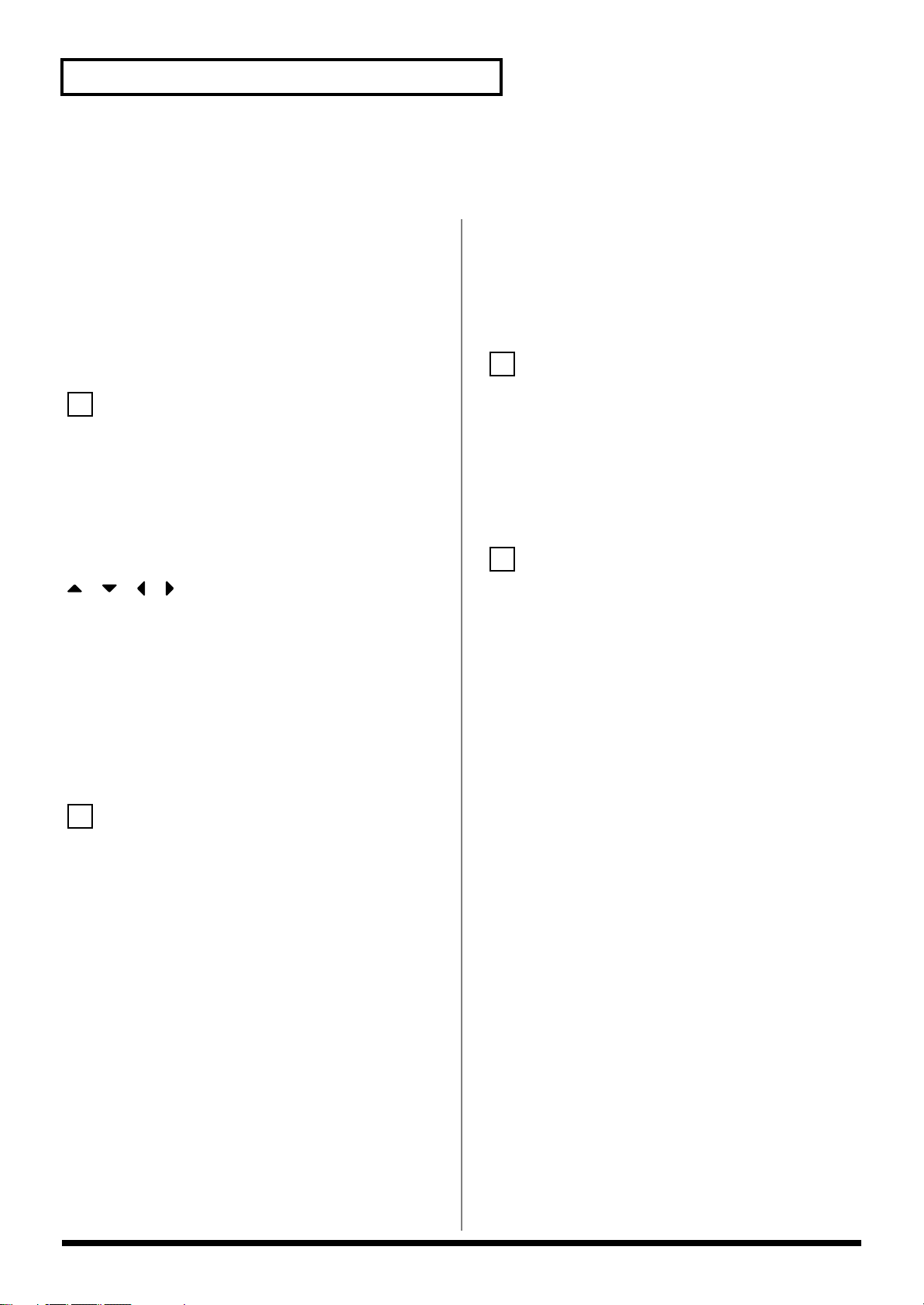
Rear Panel
3
fig.Rear
Panel Descriptions
1 2 3 4 5
1
LCD CONTRAST Knob
This knob adjusts the contrast of the top panel display.
USB Connector
This connector lets you use a USB cable to connect your computer to
the JUNO-G (p. 167, p. 170).
2
PC CARD Slot
A memory card can be inserted here (p. 178).
930
* Never insert or remove a memory card while this unit’s power is on.
Doing so may corrupt the unit’s data or the data on the memory card.
931
* Carefully insert the memory card all the way in—until it is firmly in
place.
MIDI Connectors (OUT, IN)
These connectors can be connected to other MIDI devices to receive
and transmit MIDI messages.
CONTROL PEDAL Jack
You can connect optional expression pedals (EV-5, etc.) to these
jacks. By assigning a desired function to a pedal, you can use it to
select or modify sound or perform various other control. You can
also connect optional pedal switches (DP series etc.) to sustain sound
(p. 16).
925
* Use only the specified expression pedal (EV-5; sold separately). By
connecting any other expression pedals, you risk causing malfunction
and/or damage to the unit.
HOLD PEDAL Jack
An optional pedal switch (DP series etc.) can be connected to this
jack for use as a hold pedal (p. 16).
This can also be set so it supports the use of half-pedaling
techniques. So, after connecting an optional expression pedal (DP-8/
10), you can employ pedal work to achieve even finer control in
performances in which piano tones are used.
4
AUDIO INPUT LEVEL Knob
This knob adjusts the volume of the input to the AUDIO INPUT. Use
this knob to make adjustments if the sound is still distorted even
after you lower the top panel AUDIO IN slider, or conversely if the
volume is insufficient even after setting the slider to the maximum
position (p. 104).
AUDIO INPUT Jacks (L (MONO)/MIC, R)
Accept input of audio signals in stereo (L/R) from external devices.
If you want to use mono input, connect to the L jack. When
recording from a mic, connect it to the L jack
926a
* When connection cables with resistors are used, the volume level of
equipment connected to the AUDIO INPUT jacks may be low. If this
happens, use connection cables that do not contain resistors, such as
those from the Roland PCS series.
OUTPUT A (MIX) Jacks (L (MONO)/1, R/2)
These jacks output the audio signal to the connected mixer/amplifier
system in stereo. For mono output, use the L jack (p. 14).
* You can also use these to output each part independently.
OUTPUT B Jacks (L/3, R/4)
These jacks output the audio signal to the connected mixer/amplifier
system in stereo.
* You can also use these to output each part independently.
PHONES Jack
This is the jack for connecting headphones (sold separately) (p. 14).
5
Cord Hook
Anchor the cord of the AC adaptor (p. 14).
DC IN Jack
Connect the AC adaptor here (p. 14).
Be sure to use only the supplied AC adaptor.
POWER ON Switch
Press to turn the power on/off (p. 15).
Ground Terminal
927
Depending on the circumstances of a particular setup, you may
experience a discomforting sensation, or perceive that the surface
feels gritty to the touch when you touch this device, microphones
connected to it, or the metal portions of other objects, such as guitars.
This is due to an infinitesimal electrical charge, which is absolutely
harmless. However, if you are concerned about this, connect the
ground terminal (see figure) with an external ground. When the unit
is grounded, a slight hum may occur, depending on the particulars
of your installation. If you are unsure of the connection method,
contact the nearest Roland Service Center, or an authorized Roland
distributor, as listed on the “Information” page.
Unsuitable places for connection
• Water pipes (may result in shock or electrocution)
• Gas pipes (may result in fire or explosion)
• Telephone-line ground or lightning rod (may be dangerous in
the event of lightning)
13
Page 14
Getting Ready
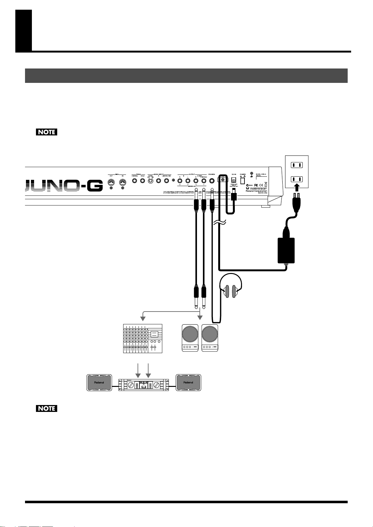
to the Power Outlet
AC adaptor
Stereo headphones
Mixer etc.
Power amp
Monitor speakers
(powered)
Connections
Since JUNO-G contains no amplifier or speakers, you’ll need to connect it to audio equipment such as a keyboard amplifier, monitor speaker
system or home stereo, or use headphones to hear its sound.
In order to fully experience the JUNO-G’s sound, we recommend using a stereo amp/speaker system. If you’re using a mono system, however,
make your connections to the JUNO-G’s OUTPUT A (MIX) jack L (MONO).
* Audio cables are not included with the JUNO-G. You’ll need to provide them.
921
To prevent malfunction and/or damage to speakers or other devices, always turn down the volume, and turn off the power on all devices
before making any connections.
fig.Connect.e
924
To prevent the inadvertent disruption of power to your unit (should the plug be pulled out accidentally), and to avoid applying undue stress
to the AC adaptor jack, anchor the power cord using the cord hook, as shown in the illustration.
14
Page 15
Getting Ready
Turning On/Off the Power
941
* Once the connections have been completed (p. 14), turn on power to
your various devices in the order specified. By turning on devices in
the wrong order, you risk causing malfunction and/or damage to
speakers and other devices.
1.
Before turning on the JUNO-G’s power, consider these two
questions:
• Are all devices connected properly?
• Have the volume controls of the JUNO-G and all connected
audio devices been turned to their lowest settings?
2.
Turn on the POWER ON switch located on the rear panel of
the JUNO-G.
942
* This unit is equipped with a protection circuit. A brief interval (a few
seconds) after power up is required before the unit will operate normally.
* To ensure proper operation of the pitch bend lever, make sure not to
touch the lever when turning the JUNO-G’s power on.
Do not touch!
Adjusting the Display Contrast (LCD Contrast)
The characters in the display may be difficult to view immediately
after turning on the JUNO-G’s power or after extended use. If this
occurs, turn the rear panel LCD CONTRAST knob to make the
display legible.
Listening to the Demo Songs
The internal demo songs will feature the JUNO-G’s exceptional
sounds and effects.
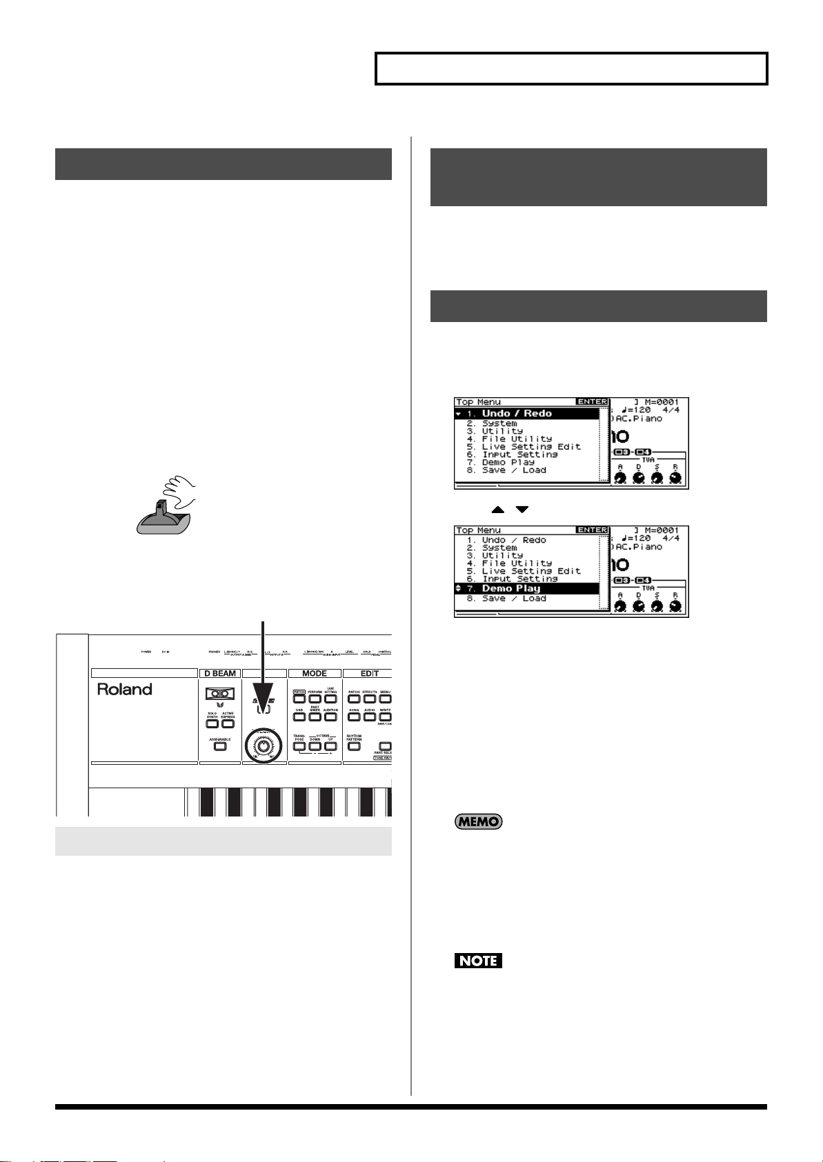
1.
Press EDIT [MENU] to open the Top Menu Window.
fig.TopMenu
Press [ ] [ ] to select “7. Demo Play.”
2.
fig.DemoPlay
3.
Turn on the power for any connected audio devices.
4.
While playing the keyboard, gradually raise the volume of
the JUNO-G and connected devices.
fig.Volume
Turning Off the Power
1.
Before turning off the power, consider these two questions:
• Have the volume controls of the JUNO-G and all connected
audio devices been turned to their lowest settings?
• Have you saved your JUNO-G sounds or other data you’ve created?
2.
Turn off the power for all connected audio devices.
3.
Press [ENTER].
The DEMO MENU screen appears.
4.
Turn the VALUE dial or use [INC] [DEC] to select a song.
5.
Press [ENTER] to start playback.
Playback will stop automatically when the song ends.
If you press [F6 (PLAY ALL)], the songs will playback
successively, beginning from the first.
* Press [EXIT] or [
6.
Press [EXIT] to return to the previous screen.
For the names and copyright information of these demo songs,
refer to the JUNO-G’s display.
981a
* All rights reserved. Unauthorized use of this material for purposes
other than private, personal enjoyment is a violation of applicable laws.
982
* No data for the music that is played will be output from MIDI OUT.
STOP
] to stop the demo song.
3.
Turn off the POWER ON switch of the JUNO-G.
When you perform demo playback, any patch or performance
you may have been editing will be lost.
15
Page 16
Various Performance Features
Roland
Velocity
The velocity—the force with which you play the keyboard—can
affect the volume or timbre of a sound.
Pitch Bend/Modulation Lever
While playing the keyboard, move the lever to the left to lower the
pitch of the currently selected patch, or to the right to raise its pitch
(
pitch bend
away from you (
If you push the lever away from you and at the same time move it to
the right or left, you can apply both effects at once.
fig.Bender.e
). You can also apply vibrato by gently pushing the lever
modulation
).
ModulationPitch Bend
Octave Shift
You can shift the pitch of the keyboard in one-octave units over a
range of +/-3 octaves.
• In the MODE section, use OCTAVE [DOWN] [UP] to adjust the
octave shift.
• To return to the original pitch, press both buttons simultaneously.
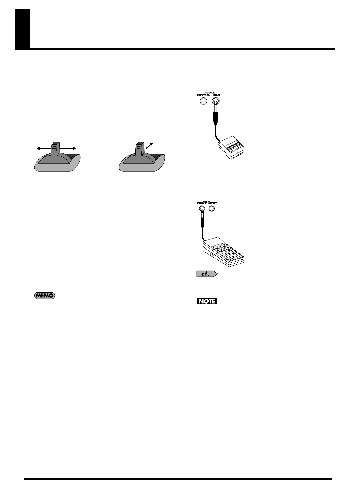
Hold Pedal
If an optional pedal switch (DP series) is connected to the rear panel
PEDAL HOLD jack, you can press the pedal to cause notes to sustain
or “hold” even after their keys have been released.
fig.HolPdl
Control Pedal
If an optional expression pedal or pedal switch (EV-5, DP series) is
connected to the rear panel PEDAL CONTROL jack, you can use the
pedal to control the volume or various function.
fig.CtrlPdl
Transpose
You can transpose the pitch of the keyboard in semitone steps, over a
range of G–F# (-5– +6 semitones).
• Hold down MODE [TRANSPOSE] and use [-] [+] to change the
transposition.
• To return to the original pitch, hold down [TRANSPOSE] and
press both buttons simultaneously.
The Octave Shift and Transpose settings are remembered even
if you change patches or performances.
For details on pedal settings, refer to
(p. 72).
925
Use only the specified expression pedal or pedal switch (EV-5,
DP series; sold separately). By connecting any other expression
pedals, you risk causing malfunction and/or damage to the unit.
Control Pedal Settings
16
Page 17
Overview of the JUNO-G
WG
Pitch
Envelope
TVF
TVF
Envelope
TVA
Envelope
TVA
LFO 1 LFO 2
control signal
Tone
audio signal
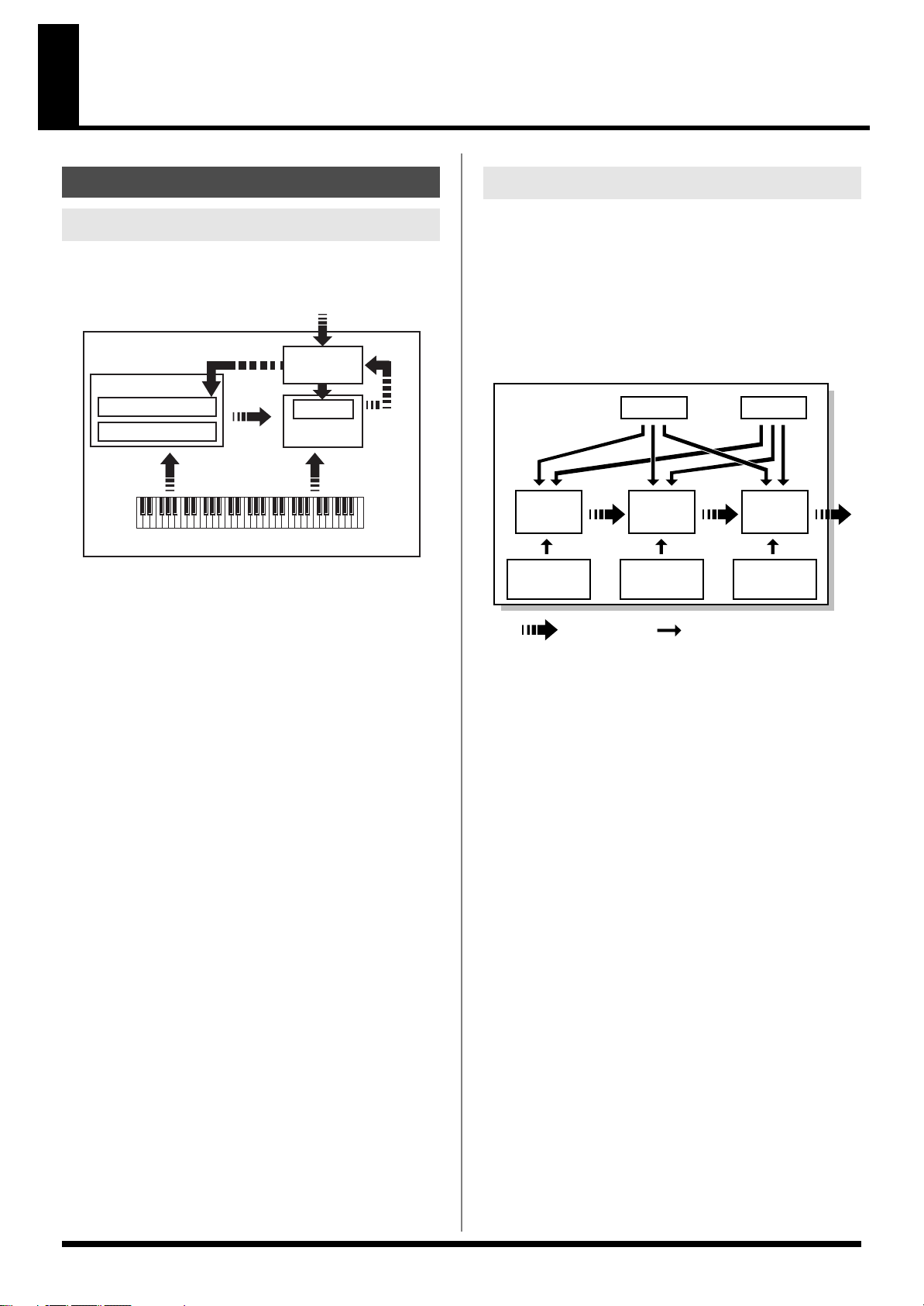
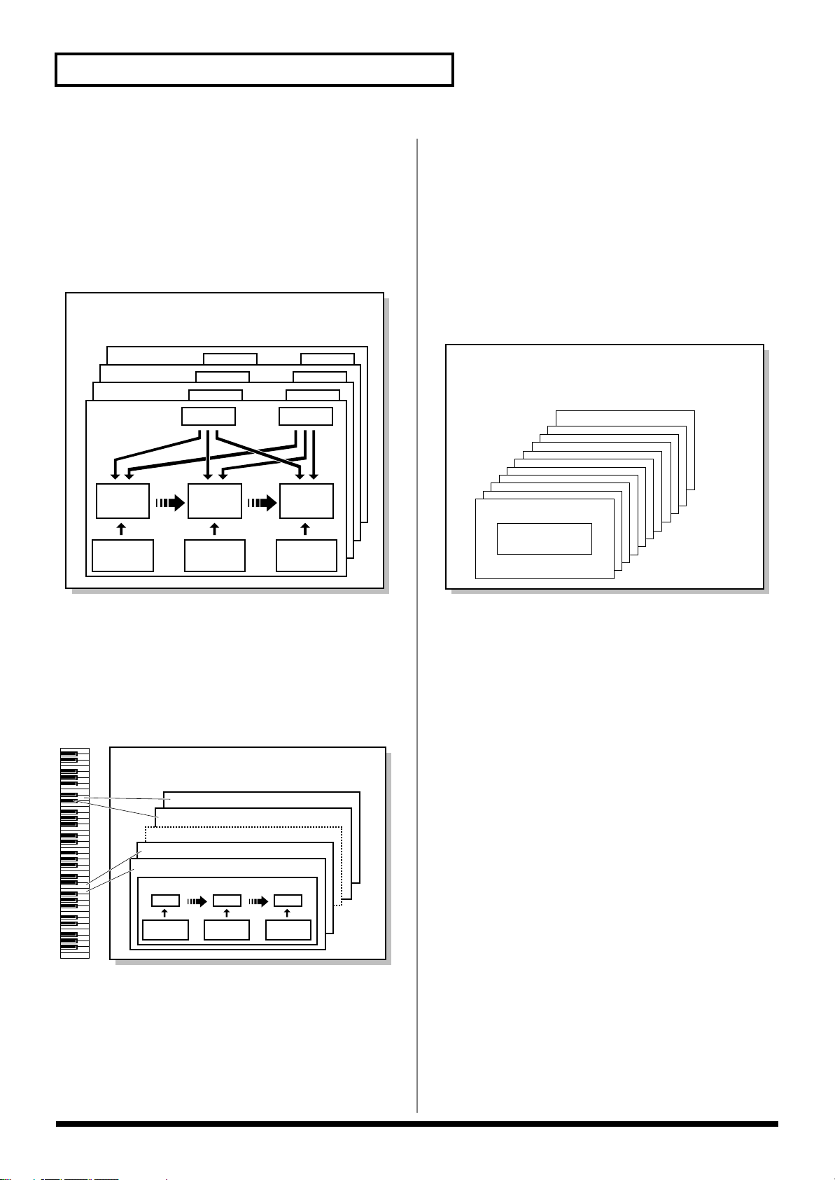
How the JUNO-G Is Organized
Basic Structure
Broadly speaking, the JUNO-G consists of a controller section, a
sound generator section, and a song recorder section.
fig.BasicStruct.e
Audio Input
Sample Event
Song Recorder Section
Audio Track
MIDI Track
Recording
Controller Section (controllers such as keyboard, pitch bend lever, etc.)
Playback
Controller Section
This section consists of the keyboard, pitch bend/modulation lever,
panel knobs and buttons, and D Beam controller. It also includes any
pedals that may be connected to the rear panel. The performance
information generated when you do things such as press/release a
key, or depress the hold pedal is converted into MIDI messages and
sent to the sound generator section, song recorder section, and/or an
external MIDI device.
Sound Generator Section
The sound generator section produces the sound. It receives MIDI
messages from the controller section and song recorder section and/
or from an external MIDI device, generates musical sound according
to the MIDI messages that were received, and outputs the sound
from the output jacks or headphones jack.
Song Recorder Section
This consists of MIDI tracks, which record keyboard and controller
operations as MIDI messages, and audio tracks, which record the
performance data (sample events) used to trigger audio phrases
(samples). The recorded data is sent to the sound generator section,
reproducing the performance. MIDI messages recorded on MIDI
tracks can also be transmitted from the MIDI OUT connector to
control external MIDI devices.
Audio Track Recording
Audio track recording lets you capture sound from a CD player or
microphone connected to the audio input jacks into the sound
generator section as a sample. Performance data for that sample is
recorded on the song recorder’s audio track as a sample event.
The captured sample can be used in an audio track, or used in the
same way as a sound generator waveform. You can also record the
performance of the internal sound generator as a sample.
The JUNO-G can load WAV or AIFF format wave files as samples
via a USB connection.
Audio Track
Recording
Sound Generator
Sample
Section
Play
Resampling
Classification of JUNO-G Sound Types
When using the JUNO-G, you will notice that a variety of different
categories come into play when working with sounds. What follows
is a simple explanation of each sound category.
Tones
On the JUNO-G, the tones are the smallest unit of sound. However,
it is not possible to play a tone by itself. The patch is the unit of
sound which can be played, and the tones are the basic building
blocks which make up the patch.
fig.Tone.e
Tones consist of the following five components.
WG (Wave Generator)
Specifies the PCM waveform (wave) that is the basis of the sound,
and determines how the pitch of the sound will change.
The JUNO-G has 1267 different waveforms. All patches built into the
JUNO-G consist of combinations of tones which are created based on
these waveforms.
* There are four wave generators for each rhythm tone (percussion
instrument sounds).
TVF (Time Variant Filter)
Specifies how the frequency components of the sound will change.
TVA (Time Variant Amplifier)
Specifies the volume changes and the sound’s position in a stereo
soundfield.
Envelope
You use Envelope to initiate changes to occur to a sound over time.
There are separate envelopes for Pitch, TVF (filter), and TVA
(volume). For example if you wish to modify the way in which the
sound attacks or decays over time, you would adjust the TVA
envelope.
LFO (Low Frequency Oscillator)
Use the LFO to create cyclic changes (modulation) in a sound. The
JUNO-G has two LFOs. You can use the LFO to apply an effect to
either the WG (pitch), the TVF (filter), or the TVA (volume). When
an LFO is applied to the WG pitch, a vibrato effect is produced.
When an LFO is applied to the TVF cutoff frequency, a wah effect is
produced. When an LFO is applied to the TVA volume, a tremolo
17
Page 18
Overview of the JUNO-G
Patch
Tone 4
Tone 3
Tone 2
Tone 1
WG
Pitch
Envelope
TVF
TVF
Envelope
TVA
Envelope
TVA
LFO 1 LFO 2
Performance
Part 16
Part 1
Patch/
Rhythm Set
LAYER/SPLIT
MIXER
effect is produced.
* LFO is not included in the rhythm tones (percussion instrument
sounds).
Patches
Patches are the basic sound configurations that you play during a
performance. Each patch can be configured by combining up to four
tones. How the four tones are combined is determined by the
Structure Type parameter (p. 35).
fig.Patch.e
Performances
A performance has a patch or rhythm set assigned to each of the 16
parts, and can simultaneously handle 16 sounds.
The JUNO-G’s performances are controlled via two screens; a Play
screen and a Part Mixer screen (p. 58).
Use the PLAY screen if you want to play two or more patches
together (Layer) or play different patches in separate areas of the
keyboard (Split).
Use the MIXER screen if you want to “mix” by individually
adjusting the pan and level settings for each of the sixteen parts.
Because the JUNO-G sound generator can control multiple sounds
(instruments), it is called a Multi-timbral sound generator.
fig.Performance.e
Rhythm Sets
Rhythm sets are groups of a number of different percussion
instrument sounds. Since percussion instruments generally do not
play melodies, there is no need for a percussion instrument sound to
be able to play a scale on the keyboard. It is, however, more
important that as many percussion instruments as possible be
available to you at the same time. Therefore, each key (note number)
of a rhythm set will produce a different percussion instrument.
fig.RhythmSet.e
Rhythm Set
Note Number 98 (D7)
Note Number 97 (C#7)
Note Number 36 (C2)
Note Number 35 (B1)
Each percussion instrument consists of the following four elements.
(For details, refer to the explanations for “Tones.”)
• WG (Wave Generator): 1–4
• TVF (Time Variant Filter)
• TVA (Time Variant Amplifier)
• Envelope
Rhythm Tone (Percussion instrument sound)
WG
Pitch
Envelope
TVF
TVF
Envelope
TVA
TVA
Envelope
Part
On the JUNO-G, a “part” is something to which you assign a patch
or rhythm set. In Patch mode you can assign a patch or rhythm set to
the keyboard. In Performance mode, each performance has sixteen
parts, and you can assign a patch or rhythm set to each part.
18
Page 19
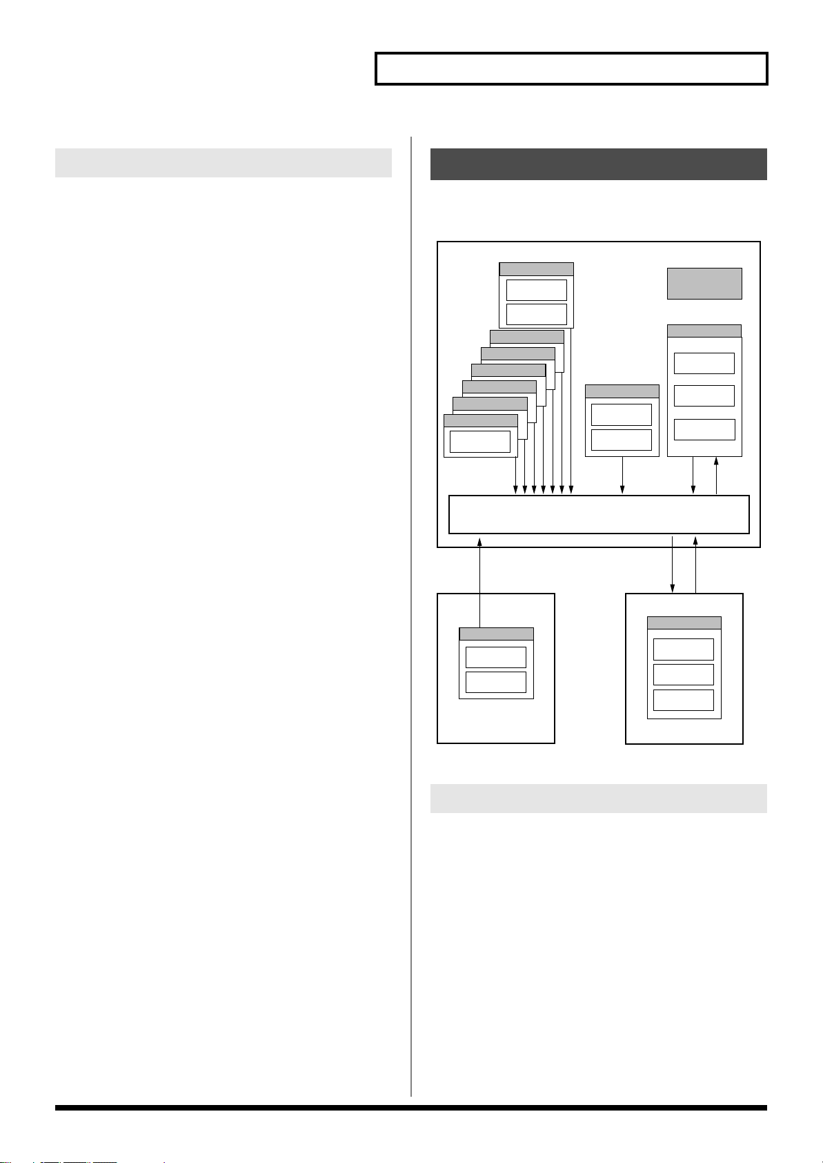
Overview of the JUNO-G
Temporary Area
Rhythm Set
32
Patch
256
Select
JUNO-G
GM (GM2)
* 1 The selected Patches/Rhythm Sets cannot be changed.
Performance
64
User (USER)
System
WriteSelect
SelectWrite
Wave Expansion Board
Memory Card
Patch
256
Rhythm Set
32
Performance
64
Rhythm Set
Patch
EXP Slot
CARD Slot
Select Select
* 1
Patch
256
Rhythm Set
9
Performance
64
Rhythm Set
36
Patch
128
Preset B (PR-B)
Preset A (PR-A)
Preset C (PR-C)
Preset D (PR-D)
Preset F (PR-F)
Preset E (PR-E)
Preset (PRST)
About Simultaneous Polyphony
The JUNO-G can play a maximum of 128 sounds simultaneously.
The following paragraphs discuss what this means, and what will
happen when more than 128 simultaneous voices are requested from
the JUNO-G.
Calculating the Number of Voices
Being Used
The JUNO-G is able to play up to 128 notes simultaneously. The
polyphony, or the number of voices (sounds) does not refer only to
the number of patches actually being played, but changes according
to the number of tones used in the patches, and the number of waves
used in the tones. The following method is used to calculate the
number of sounds used for one patch being played.
(Number of patches being played) x (Number of tones used by
patches being played) x (Number of waves used in the tones)
For example, a patch that combines four tones, each of which use
two waves, will use eight notes of polyphony at once. Also, when
playing in Performance mode, the number of sounds for each part is
counted to obtain the total number of sounds for all parts.
How a Patch Sounds
When the JUNO-G is requested to play more than 128 voices
simultaneously, currently sounding notes will be turned off to make
room for newly requested notes. The note with the lowest priority
will be turned off first. The order of priority is determined by the
Patch Priority setting (p. 34).
Patch Priority can be set either to “LAST” or “LOUDEST.” When
“LAST” is selected, a newly requested note that exceeds the 128
voice limit will cause the first-played of the currently sounding notes
to be turned off. When “LOUDEST” is selected, the quietest of the
currently sounding notes will be turned off. Usually, “LAST” is
selected.
Note Priority in Performance Mode
Since Performance mode is usually used to play an ensemble
consisting of several patches, it is important to decide which parts
take priority. Priority is specified by the Voice Reserve settings (p.
66). When a note within a patch needs to be turned off to make room
for a new note, the Patch Priority setting of the patch will apply (p.
34).
Voice Reserve
The JUNO-G has a Voice Reserve function that lets you reserve a
minimum number of notes that will always be available for each
part. For example if Voice Reserve is set to “10” for part 16, part 16
will always have 10 notes of sound-producing capacity available to it
even if a total of more than 128 notes (total for all parts) are being
requested. When you make Voice Reserve settings, you need to take
into account the number of notes you want to play on each part as
well as the number of tones used by the selected patch (p. 66).
It is not possible to make Voice Reserve settings that would cause the
total of all parts to be greater than 64 voices.
About Memory
Patch and performance settings are stored in what is referred to as
memory. There are three kind of memory: temporary, rewritable,
and non-rewritable.
fig.04-006.e
Temporary Memory
Temporary Area
This is the area that holds the data for the patch or performance that
you’ve selected using the panel buttons.
When you play the keyboard or play back a sequence, sound is
produced based on data in the temporary area. When you edit a
patch or performance, you do not directly change the data in
memory; rather, you call up the data into the temporary area, and
edit it there.
Settings in the temporary area are temporary, and will be lost when
the power is turned off or when you select another patch/
performance. To keep the settings you have changed, you must write
them into rewritable memory.
19
Page 20
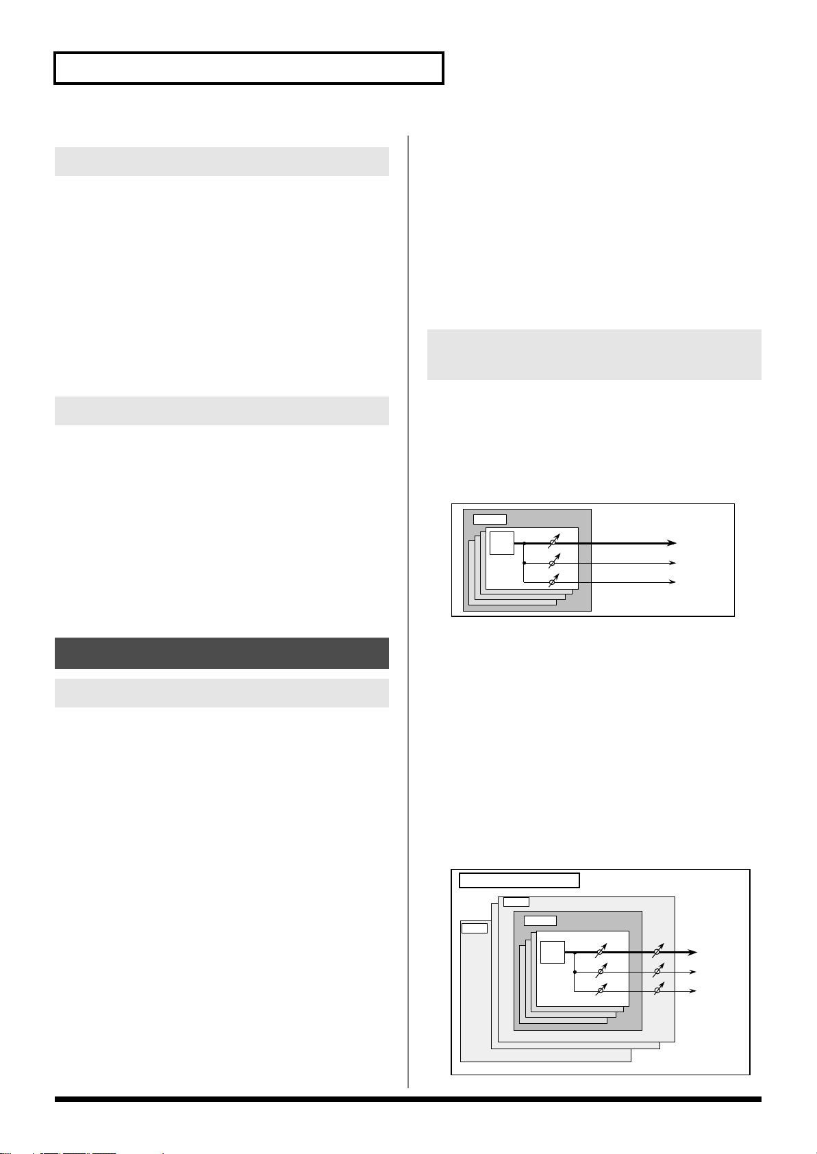
Overview of the JUNO-G
TONE
Patch
Chorus
Reverb
Multi-Effects
Chorus
Reverb
Multi-Effects
Performance/Multitimbre
Part16
TONE
Patch
Part 1
Rewritable Memory
System Memory
System memory stores system parameter settings that determine
how the JUNO-G functions.
User Memory
User memory is the internal memory area that holds patches,
performances, samples, and performance data.
Reverb
Reverb adds the reverberation characteristics of halls or
auditoriums. Five different types are offered, so you can select and
use the type that suits your purpose.
Mastering Effect
This is a stereo compressor (limiter) that is applied to the final
output of the JUNO-G. It has independent high, mid, and low
ranges. Independently for the high-frequency, mid-frequency, and
low-frequency regions, this compresses any sounds that exceed the
specified level, making the volume more consistent.
Memory Card
You can use a memory card to store patches, performances, samples,
and performance data just as you can in User memory.
Non-Rewritable Memory
Preset Memory
Data in Preset memory cannot be rewritten. However, you can call
up settings from preset memory into the temporary area, modify
them and then store the modified data in rewritable memory (except
GM2).
Wave Expansion Board (SRX Series)
The JUNO-G can be equipped with a Wave Expansion Board (SRX
series; sold separately). Wave Expansion Boards contain Wave data,
as well as patches and rhythm sets that use this Wave data, which
can be called directly into the temporary area and played.
About the Onboard Effects
Effect Types
The JUNO-G has built-in effect units, and you can independently
edit each unit’s settings.
Multi-Effects
The multi-effects are multi-purpose effects that completely change
the sound type by changing the sound itself. Contained are 78
different effects types; select and use the type that suits your aims. In
addition to effects types composed of simple effects such as
Distortion, Flanger, and other such effects, you can also set up a
wide variety of other effects, even connecting effects in series or in
parallel. Furthermore, while chorus and reverb can be found among
the multi-effects types, the following chorus and reverb are handled
with a different system. In Performance mode, three types of multieffect can be used simultaneously; these are referred to as MFX1,
MFX2, and MFX3. In Patch mode you can use MFX1 and MFX2.
Chorus
Chorus adds depth and spaciousness to the sound. You can select
whether to use this as a chorus effect or a delay effect.
20
How Effects Units Work in Different Modes
In Patch Mode
Multi-effects can be used individually by each patch and rhythm set.
Chorus and reverb are each shared by patches and rhythm sets; the
same effect applies to each tone. Adjusting the signal level to be sent
to each effects unit (Send Level) provides control over the effect
intensity that’s applied to each tone.
fig.FXinPatch
* To each part you can assign either a Patch or a Rhythm Set.
In the Performance Mode
The multi-effects, chorus and reverb can be set individually for each
performance. The intensity of each effect will be set for each part.
When you apply effects in Performance mode, the effect settings of
the patch or rhythm set assigned to each part will be ignored, and
the effect settings of the performance will be used. Thus, the effects
for the same patch or rhythm set may differ when played in Patch
mode and in Performance mode. However, depending on the
settings, you can have effect settings for a patch or rhythm set
assigned to a part applied to the entire performance. In addition,
when using the multi-effects settings of a performance, you can use
three different multi-effects simultaneously, depending on the effect
type.
fig.FXinPfm.e
Page 21
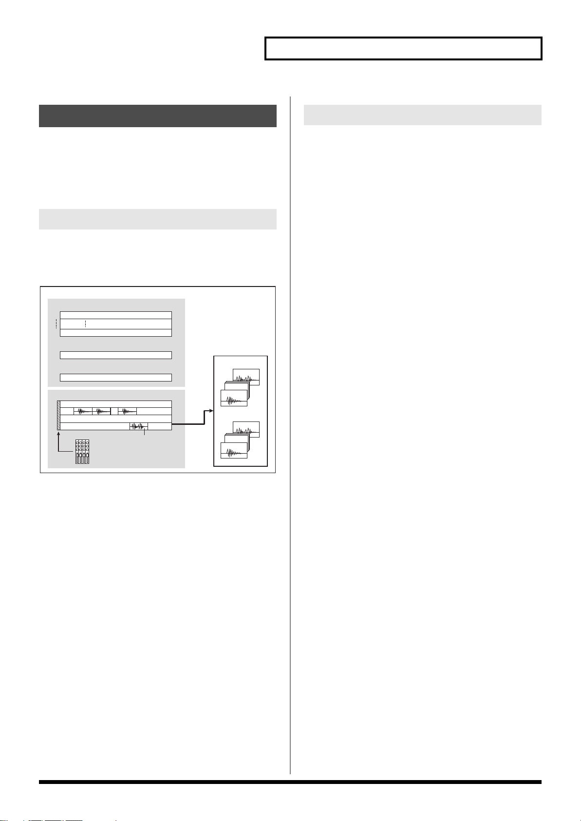
Overview of the JUNO-G
USER
Sample
CARD
MIDI Tracks (.SVQ)
C7000
C0002
U2000
U0002
U0001
C0001
1
16
AUDIO Tracks (.SVA)
1
2
sample event
Setup Mixer
Track settings are stored at the beginning of the song.
Up to 256 events can be placed in a track.
Referenced
Song
3
4
Tempo Track
Beat Track
About the Song Recorder
The song recorder records performance data from the keyboard and
controllers and performance data for the samples created by audio
track recording, and manages this data as a “song.” When you play
back the song recorder, this performance data is sent to the sound
generator, causing it to generate sound and reproduce the recorded
performance.
What Is a Song?
For the JUNO-G, musical performance data for one song or
composition is referred to as a
performance data recorded on the MIDI tracks (MIDI channels 1–16),
the tempo track, the beat track, and audio tracks 1–4.
fig.Song.e_71
song
. This consists of the
What Is a Track?
Each section of a song which stores musical performance data is
called a
track
.
MIDI Tracks 1–16
MIDI tracks record your keyboard playing and controller operations
as MIDI messages. When you play back a song, the MIDI tracks send
these recorded MIDI messages to the sound generator, causing it to
produce sound. MIDI tracks actually plays instruments instead of
the musician, and since it can record a musical performance, it is a
tape recorder as well.
But in reality MIDI tracks doesn’t record sound, but actually the
steps that cause the sound generator to produce sound, so it offers
several advantages. Sound quality is always excellent, the equivalent
of first-generation tape, no matter how many times the data plays
back; tempo changes have no effect on pitch; detailed editing is
possible, etc.
The MIDI tracks can record performance data for sixteen MIDI
channels. In Performance mode, the sound generator’s sixteen parts
correspond to the sixteen MIDI channels. In Patch mode, the
keyboard performance is recorded on MIDI channel 1 and the
rhythm pattern performance is recorded on MIDI channel 10 (with
the default settings).
Audio Tracks 1–4
Audio tracks handle the samples you’ve captured by audio track
recording, as well as imported samples.
Even if you change the tempo during the song, audio tracks will be
time-stretched so that they will continue playing in synchronization
with the song. You can also play back from the middle of a sample.
Audio tracks do not record the sample itself; they only contain
information that tells the sound generator to “play USER (or CARD)
sample number ‘x’ at this point.” (This information is called a
“sample event.”) This means that even if you delete a sample event
from the audio track, the sample data itself will remain.
Up to 256 sample events can be placed on each audio track.
* Each audio track can play back only one sample at a time. If there are
overlapping sample events on an audio track, the sample event located
later will be given priority.
Tempo Track
The Tempo track records tempo changes of a song over time. It can
be used for tempo changes during a song. If a song has the same
tempo from beginning to end, the Tempo track can be ignored.
When a song is first recorded on the JUNO-G, a tempo setting at the
time of recording will be stored at the beginning of the Tempo track.
Therefore when song playback starts from the beginning, the song
will always play back at this initial tempo.
Thus playback tempo is determined by the Tempo track setting. If
you modify the tempo during playback, the overall tempo of the
song will be controlled by the setting you make.
Beat Track
The Beat track records the time signature of each measure of a song.
Set the Beat track when recording a new song, or when you want to
change time signature during a song.
21
Page 22
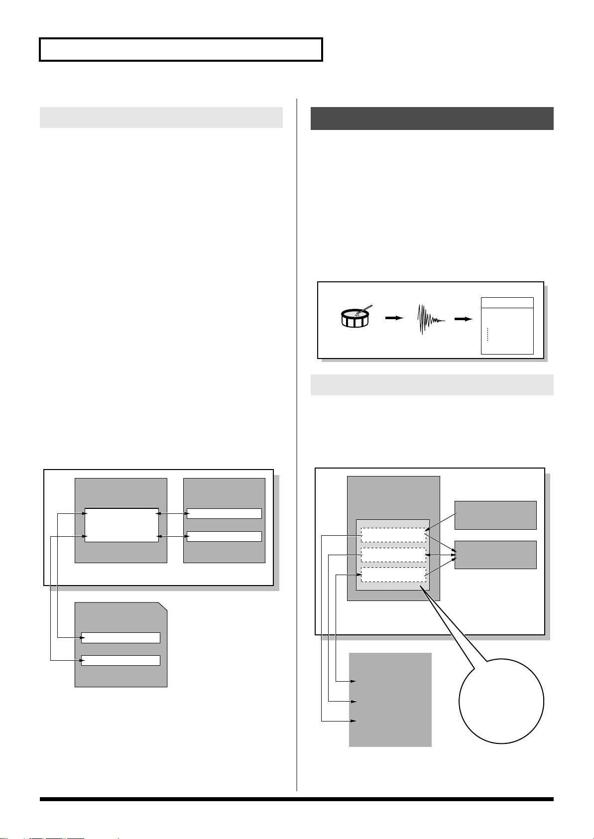
Overview of the JUNO-G
Sample
Audio
Recording
Drum
Sample List
0001
0002
2000
User Sample
Wave
(Sample)
Added
automatically
Positions for Storing a Song
Temporary Area
The song recorder has an area called
temporarily store one song. So we call this
The song in Temporary Area is volatile and will be lost when the
power is turned off. To keep a song, you must save it to user
memory or memory card.
Memory Card/User Memory
If you want to keep the song in Temporary Area that you recorded
or edited, you must save it as a song file onto a memory card or into
user memory. Either method lets you save up to 256 songs.
A card and user memory can contain two file types. The three-letter
symbol shown in parentheses ( ) is a file name extension that
distinguishes the different file types.
Song File (.SVQ, .SVA)
Each song you create on the JUNO-G is saved as two files; a file with
a name consisting of the song name and an extension of “
SVQ file), and a file with an extension of “
SVQ file contains mainly the data of the MIDI tracks. The SVA file
contains mainly the audio track data (sample events).
Standard MIDI File (.MID)
Standard MIDI File
data to be exchanged between most musical applications. JUNO-G
files can be saved as Standard MIDI Files. This also allows you to
play back commercially available music data (GM scores) that is
compatible with the GM/GM2 system.
fig.SongFile.e
is a standard file format that allows sequencer
Temporary Area
temporary song
.SVA
” (the SVA file). The
that can
.
.SVQ
” (the
About Audio Track Recording
Audio track recording lets you record external input sources such as
an audio device or microphone as digital audio data. A sound you
record can be played as a patch (sample patch), or used as the
waveform for a patch or drum set. You can also import WAV/AIFF
format files and use them in the same way.
Samples
A “
sample
” is a waveform (a piece of sound) obtained by recording
an audio track on the JUNO-G. In addition to the actual waveform
data itself, a sample also contains parameters such as start point,
loop start, and loop end. The JUNO-G can hold 9,000 samples (User:
2000, Card: 7000).
fig.Sample.e
Where Samples are Stored
Samples that you record or import are stored in sample memory.
This sample memory is temporary, and its data will be lost when
you turn off the power. If you want to keep these samples, you must
save them to user memory or a memory card.
* You cannot save data to the preset memory.
fig.SampleMemory.e
22
Temporary Memory
Temporary Area
Memory Card
Song file
Standard MIDI file
User Memory
Standard MIDI file
Song file
JUNO-G
Write
Write
Load/Write
Sample Memory
Preset Bank
User Bank
Card Bank
Memory Card
Load
Write
Load
Write
Write
Preset Memory
User Memory
Audio Recording
JUNO-G
Page 23
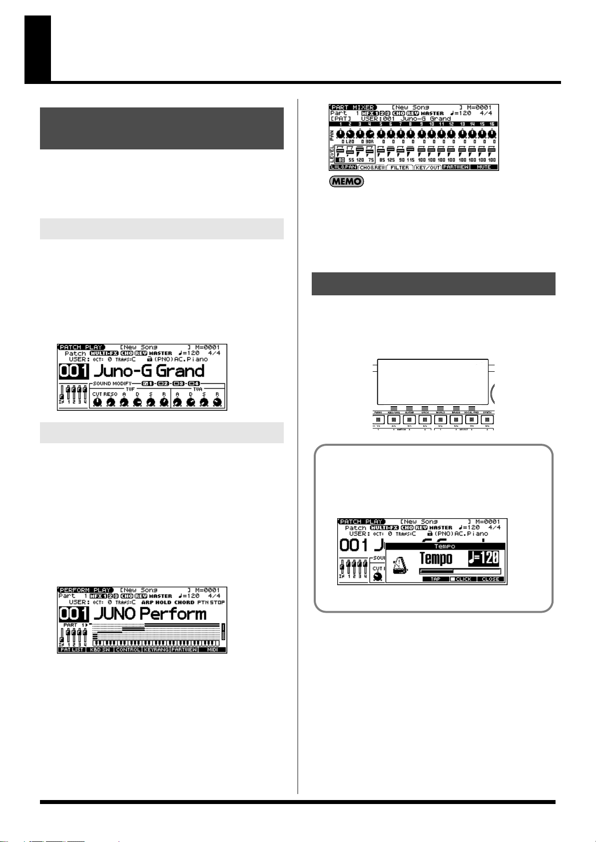
Basic Operation of the JUNO-G
fig.PatchPlay
Switching the Sound Generator Mode
The JUNO-G has two sound generating modes: Patch mode,
Performance mode. You can select the sound generating mode
(state) that is most appropriate for how you are playing the JUNO-G.
Use the following procedure to switch between these modes.
Patch Mode
This is the mode you’ll use to play a single sound (patch/rhythm set)
from the keyboard.
The keyboard and sound generator are connected by a single MIDI
channel.
The PERFORM PLAY screen and PART MIXER screen provide
different views of the same performance. For example, you’ll
want to use the PERFORM PLAY screen when you’re setting up
a keyboard split, or use the PART MIXER screen when you’re
adjusting the effect settings or volume balance of the patches for
each part.
About the Function Buttons
To select Patch mode
1.
Press MODE [PATCH].
fig.PatchPlay
Performance Mode
This mode allows you to combine multiple sounds (patches or
rhythm sets).
PERFORM PLAY screen
Use this screen when you want to play two or more sounds
(patches/rhythm sets) together.
You can play patches together (Layer) or divide the keyboard into
two regions and play different patches in each region (Split).
Press MODE [PERFORM].
1.
fig.PatchPlay
The six [KBD/ORG]–[VOCAL/PAD] buttons located below the
display execute various functions (function buttons), and their
operation will differ depending on the screen. Functions will be
listed in the bottom of the screen.
fig.FButtons
Window
The somewhat smaller screens that appear temporarily on top
of the normal screens are called windows. Various types of
windows appears according to the situation. Some display lists,
others allow you to make settings, and still others ask you to
confirm an operation.
fig.Tempo
Press [EXIT] to close the window. Some windows will close
automatically when an operation is performed.
MIXER screen
Use this screen when you want to mix the sounds by adjusting the
level and pan for each of the 16 parts.
1.
Press MODE [PART MIXER].
23
Page 24
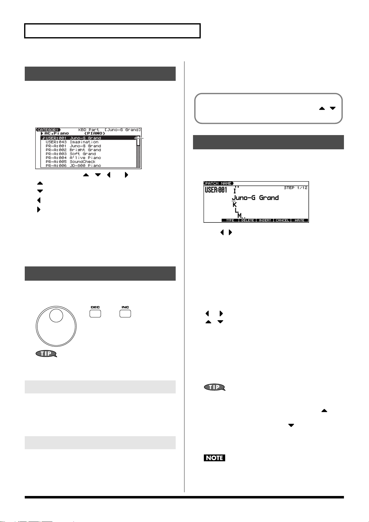
Basic Operation of the JUNO-G
Moving the Cursor
A single screen or window displays multiple parameters or items for
selection. To edit the setting of a parameter, move the cursor to the
value of that parameter. To select an item, move the cursor to that
item. When selected with the cursor, a parameter value or other
selection is highlighted.
fig.CursorScreen
and press [INC].
• If you press [INC] or [DEC] while holding down [SHIFT], the
value increments will get bigger.
When the cursor is located at a parameter value, press [ENTER]
to display a window where you can set the value. Use [ ] [ ]
to select a value, and then press [ENTER] to finalize the setting.
Cursor
Move the cursor with the [ ], [ ], [ ] and [ ] (cursor buttons).
[ ]: moves the cursor up.
[ ]: moves the cursor down.
[ ]: moves the cursor to the left.
[ ]: moves the cursor to the right.
• If you hold down one cursor button while you also press the
cursor button for the opposite direction, the cursor will move
more rapidly in the direction of the first-pressed cursor button.
• When you press [ENTER], the value of the parameter selected
by the cursor may appear in a list. This is convenient when you
want to see what your choices are.
Changing a Value
To change the value, use the VALUE dial or the [INC] [DEC]
buttons.
fig.VALUE
Assigning a Name
On the JUNO-G, you can assign names to each patch, rhythm set,
performance, Song and Sample. The procedure is the same for any
type of data.
fig.PatchName
1.
Press [ ] [ ] to move the cursor to the location where you
wish to input a character.
Turn the VALUE dial, or press [INC] [DEC] to specify the
2.
character.
• [F2 (TYPE)]: Selects the type of character. Each time you
press this, you will alternately select the first
character of a character set: uppercase (A),
lowercase (a), or numerals and symbols (0).
• [F3 (DELETE)]: Deletes the character at the cursor location.
• [F4 (INSERT)]: Inserts a space at the cursor location.
• [ ] or [ ]: Move the cursor.
• [ ], [ ]: Switch between uppercase and lowercase
letters.
* If you decide to discard your input, press [F5 (CANCEL)].
In each screen of the JUNO-G, you can use the cursor buttons to
move the area displayed as highlighted, and modify its value.
VALUE Dial
Turning the VALUE dial clockwise increases the value,
counterclockwise decreases the value.
• Holding down [SHIFT] as you move the VALUE dial increases
value increments so you can make large value changes faster.
[INC] and [DEC]
Pressing [INC] increases the value, and [DEC] decreases it.
• Keep the button pressed for continuous adjustment.
• For faster value increases, keep [INC] pressed down and press
[DEC]. For decreasing value faster, keep [DEC] pressed down
24
Available Characters/Symbols
space, A–Z, a–z, 0–9, ! “ # $ % & ` ( ) * + , - . / : ; < = > ? @ [ \ ] ^
_ ` { | }
From a naming screen you can press [MENU] and select “1.
Undo” to return the name to what it was before you changed it.
From [MENU] you can select “2. To Upper” or press [ ] to
change the character at the cursor to uppercase. From [MENU]
you can select “3. To Lower” or press [ ] to change the
character at the cursor to lowercase. From [MENU] you can
select “4. Delete All” to clear all the characters you were
inputting.
Song file names may not contain lowercase characters or certain
symbols (“ * + , . / : ; < = > ? [ \ ] |).
Page 25
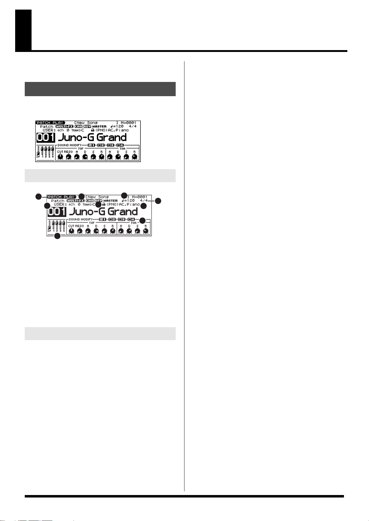
Playing in Patch Mode
Patch mode lets you play a single sound (patch/rhythm set) from
the keyboard.
About the PATCH PLAY Screen
Press MODE [PATCH]. You will enter Patch mode, and the PATCH
PLAY screen appears.
fig.PatchPlay
Functions in the PATCH PLAY Screen
fig.PatchFunc
1
5
8
1.
Indicates the current sound generating mode.
2.
Indicates multi-effects (MFX), chorus (CHO), reverb (REV), and
mastering (MASTER) on and off.
3.
Indicates the name of the currently selected song, the measure location.
4.
Indicates the time signature, and the tempo.
5.
Indicates/selects the group, number, and name of the selected patch.
6.
Indicates the octave and transposition values.
7.
Indicates the patch category group.
8.
Positions of the five SONG RECORDER sliders
9.
SOUND MODIFY settings
2
6
Patch/Rhythm Set Group
The JUNO-G has several patch groups, including the User group and
Preset groups A–F and GM, with each group storing 128 patches
(256 in GM, USER). What’s more, you can further expand your
options by installing an optional Wave Expansion Board (SRX series;
sold separately), enabling you to select from a huge assortment of
available patches. There are also sample patches (USAM, CSAM)
that can use samples as patches.
USER
This is the group inside the JUNO-G which can be rewritten. Patches
you yourself create can be stored in this group. The JUNO-G
includes 256 preset patches and 32 rhythm sets.
3
4
7
9
PR-A–F (Preset A–F), PRST (Preset)
This is the group inside the JUNO-G which cannot be rewritten.
However you may modify the settings of the currently selected
patch, and then store the modified patch in User memory. Groups
A–F already contain 128 prepared patches each, for a total of 768
patches.
GM (General MIDI 2)
This is an internal group of patches compatible with General MIDI 2,
a system of MIDI function specifications designed to transcend
differences between makers and types of devices; these patches
cannot be overwritten. Furthermore, settings of currently selected
patches from this group cannot be changed. The JUNO-G includes
256 preset patches.
CARD (Memory Card)
This group lets you use patches stored on a memory card inserted in
the rear panel card slot. Since the data in this group can be rewritten,
you can use this group to store patches that you create.
USAM (User Sample)
You can use a sample from user memory as a patch (the Sample
Patch function), and play the sample in a pitched fashion just as a
conventional patch.
* If there are no samples in memory, this will indicate “Empty.”
* Since a stereo sample uses two adjacent sample numbers, you should
choose the L-channel sample number (the lower number). It will play
as a stereo patch. (If you choose the sample number for the R channel,
“---” will be indicated for it, and it will not be playable.
CSAM (Card Sample)
You can use a sample from card memory as a patch (the Sample
Patch function), and play the sample in a pitched fashion just as a
conventional patch.
* If there are no samples in memory, this will indicate “Empty.”
* Since a stereo sample uses two adjacent sample numbers, you should
choose the L-channel sample number (the lower number). It will play
as a stereo patch. (If you choose the sample number for the R channel,
“---” will be indicated for it, and it will not be playable.
EXP (Wave Expansion Board installed in EXP Slot)
These are groups used when using patches from Wave Expansion
Board installed in the EXP slot, and cannot be rewritten. However
you may modify the settings of the currently selected patch, and
then store the modified patch in User memory and Memory card.
The number of onboard patches depends on the specific Wave
Expansion Board installed.
* EXP patches can be selected only if a Wave Expansion Board (SRX
series; sold separately) is installed in the slot.
25
Page 26
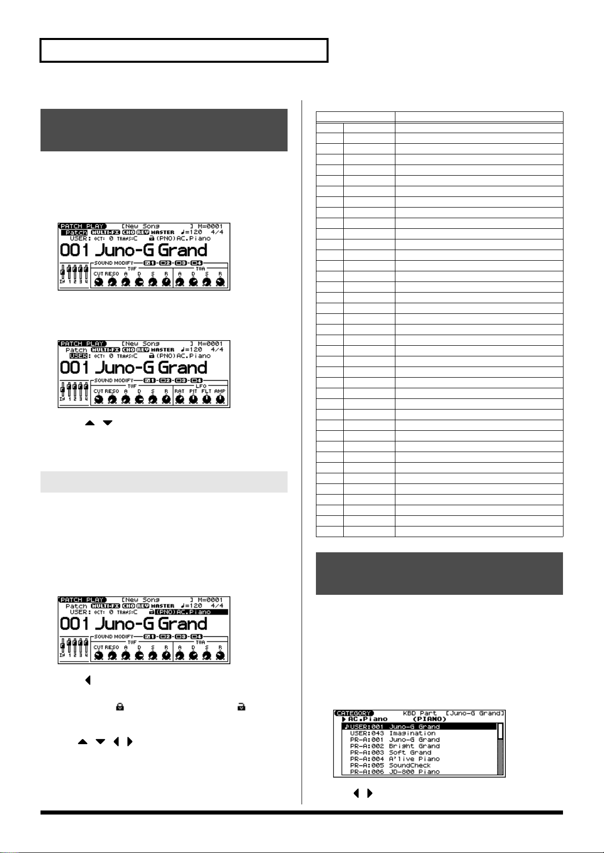
Playing in Patch Mode
Selecting Patches in the Main Screen
Press MODE [PATCH] to access the PATCH PLAY screen.
1.
To switch patches or rhythm sets, move the cursor to the
2.
location shown below and use the VALUE dial or [INC]
[DEC] to make your selection.
fig.PatchPlay
To select a patch (rhythm set) group, move the cursor to the
3.
location shown below and use the VALUE dial or [INC]
[DEC] to make your selection.
fig.PatchPlay
4.
Press [ ] [ ] to move the cursor to the patch number.
Use the VALUE dial or [INC] [DEC] to select a patch (or a
5.
rhythm set).
Selecting Patches by Category
The JUNO-G allows you to specify a type (category) of patch so that
you can quickly find the desired patch. There are a total of 38
categories.
The following categories can be selected.
Category
- - -
No Assign No assign
PNO AC.Piano Acoustic Piano
EP EL.Piano Electric Piano
KEY Keyboards Other Keyboards (Clav, Harpsichord etc.)
BEL Bell Bell, Bell Pad
MLT Mallet Mallet
ORG Organ Electric and Church Organ
ACD Accordion Accordion
HRM Harmonica Harmonica, Blues Harp
AGT AC.Guitar Acoustic Guitar
EGT EL.Guitar Electric Guitar
DGT Dist.Guitar Distortion Guitar
BS Bass Acoustic & Electric Bass
SBS Synth Bass Synth Bass
STR Strings Strings
ORC Orchestra Orchestra Ensemble
HIT Hit&Stab Orchestra Hit, Hit
WND Wind Winds (Oboe, Clarinet etc.)
FLT Flute Flute, Piccolo
BRS AC.Brass Acoustic Brass
SBR Synth Brass Synth Brass
SAX Sax Sax
PLK Plucked Plucked (Harp etc.)
ETH Ethnic Other Ethnic
FRT Fretted Fretted Inst (Mandolin etc.)
BPD Bright Pad Bright Pad Synth
SPD Soft Pad Soft Pad Synth
VOX Vox Vox, Choir
HLD Hard Lead Hard Synth Lead
SLD Soft Lead Soft Synth Lead
TEK Techno Synth Techno Synth
PLS Pulsating Pulsating Synth
FX Synth FX Synth FX (Noise etc.)
SYN Other Synth Poly Synth
PRC Percussion Percussion
SFX Sound FX Sound FX
BTS Beat&Groove Beat and Groove
DRM Drums Drum Set
CMB Combination Other patches which use Split and Layer
Contents
Press MODE [PATCH] to access the PATCH PLAY screen.
1.
2.
Move the cursor to the location shown below, and use the
VALUE dial or [INC] [DEC] to select a category.
fig.PatchPlay
3.
Press [ ] to move the cursor one space to the left, and use
the VALUE dial or [INC] [DEC] to lock the padlock symbol.
* If you don’t lock ( ) the category (the padlock symbol ) here, you
won’t be able to select patches by category.
4.
Use [ ] [ ] [ ] [ ] to move the cursor to the patch group/
number, and use the VALUE dial or [INC] [DEC] to select a
patch.
* If you didn’t lock the category in step
, you will step through the
3
patch numbers in order.
26
Using the Category Group Buttons to Select Patches
You can use the category group buttons to quickly find the patch
you want. The 38 categories and rhythm sets are organized into ten
category groups that are assigned to these buttons.
1.
Press MODE [PATCH] to access the PATCH PLAY screen.
2.
With [TONE SW/SEL] unlit, press one of the [RHYTHM]–
[BASS] (category group buttons) to select the category
group for the desired patch.
fig.PatchPlay
Use [ ] [ ] to select the category.
3.
Page 27
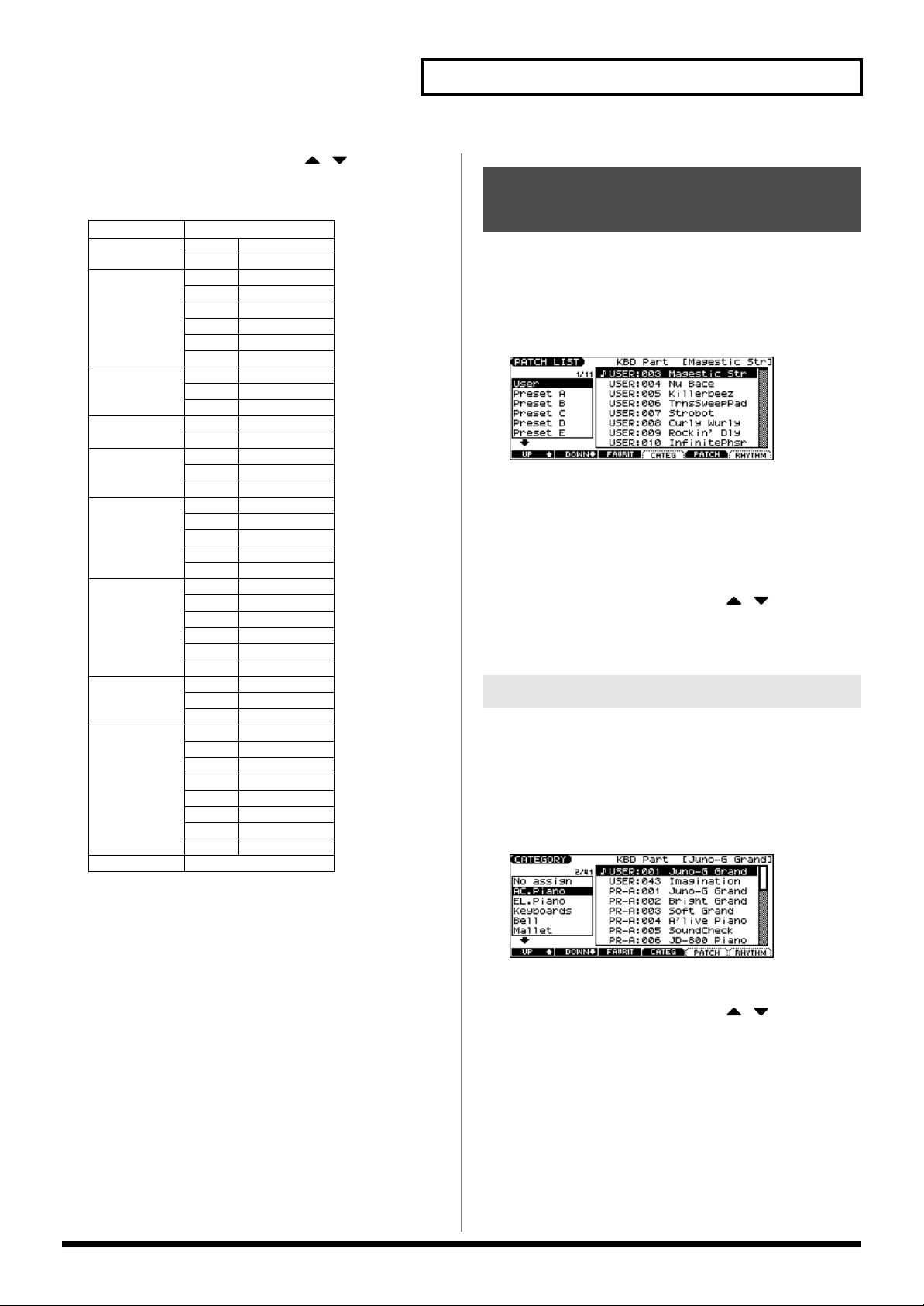
Use the VALUE dial, [INC] [DEC], or [ ] [ ] to select a
4.
patch/rhythm set.
5.
Press [ENTER] to confirm your selection.
Category Group
PIANO
ORG/KBD KEY Keyboards
GUITAR AGT AC.Guitar
BASS BS Bass
ORCH STR Strings
BRASS WND Wind
SYNTH HLD Hard Lead
VOCAL/PAD BPD Bright Pad
WORLD PLK Plucked
RHYTHM RHYTHM SET
Category
PNO AC.Piano
EP EL.Piano
BEL Bell
MLT Mallet
ORG Organ
ACD Accordion
HRM Harmonica
EGT EL.Guitar
DGT Dist.Guitar
SBS Synth Bass
ORC Orchestra
HIT Hit&Stab
FLT Flute
BRS AC.Brass
SBR Synth Brass
SAX Sax
SLD Soft Lead
TEK Techno Synth
PLS Pulsating
FX Synth FX
SYN Other Synth
SPD Soft Pad
VOX Vox
ETH Ethnic
FRT Fretted
PRC Percussion
SFX Sound FX
BTS Beat&Groove
DRM Drums
CMB Combination
Playing in Patch Mode
Selecting Patches from the List
You can display a list of patches and select a patch from that list.
Press MODE [PATCH] to access the PATCH PLAY screen.
1.
2.
Press [ENTER].
The PATCH LIST screen appears.
fig.PatchPlay
To select a patch, press [F5 (PATCH)].
3.
To select a rhythm set, press [F6 (RHYTHM)].
If you press [F6 (RHYTHM)], the RHYTHM LIST screen
appears.
Press [F1 (UP)] [F2 (DOWN)] to select a group.
4.
Use the VALUE dial, [INC] [DEC], or [ ] [ ] to select a
5.
patch/rhythm set.
Press [ENTER] to confirm your selection.
6.
Selecting Patches by Category
Press MODE [PATCH] to access the PATCH PLAY screen.
1.
Press [ENTER].
2.
The PATCH LIST screen appears.
Press [F4 (CATEG)].
3.
The CATEGORY screen appears.
4.
Press [F1 (UP)] [F2 (DOWN)] to select a category.
5.
Use the VALUE dial, [INC] [DEC], or [ ] [ ] to select a
patch.
6.
Press [ENTER] to confirm your selection.
27
Page 28
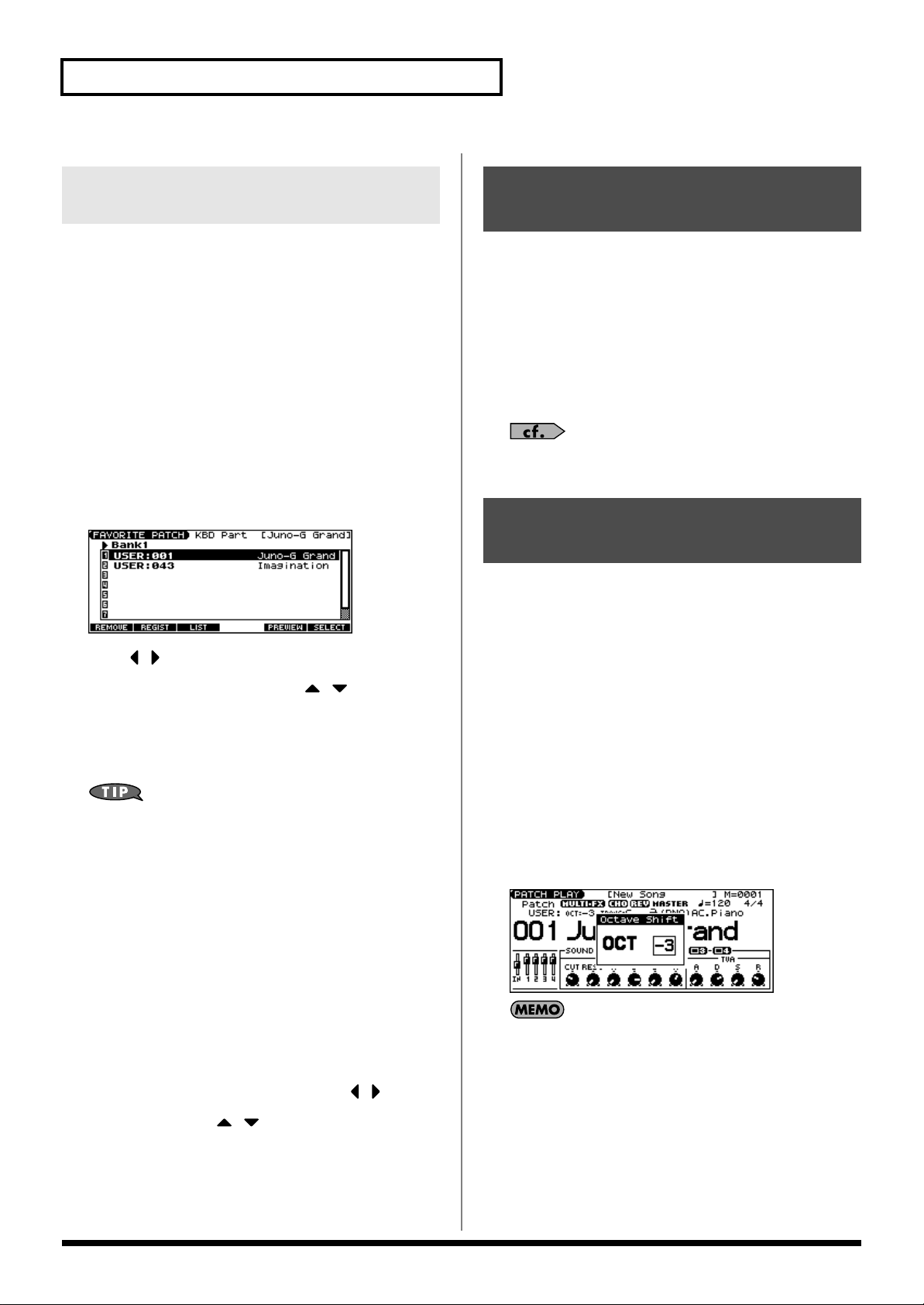
Playing in Patch Mode
Selecting Favorite Patches/Rhythm Sets (Favorite Patch)
In the patch mode, you can bring together your favorite and most
frequently used patches (or rhythm sets) in one place by registering
them in the favorite patch. By using this function, you can rapidly
select favorite patches from Preset/User/Card area or a Wave
Expansion Board. You can register a total of 64 sounds (8 sounds x 8
banks) as favorite patches.
Registering a Favorite Patch/Rhythm Set
In the PATCH PLAY screen, select the patch (or rhythm set)
1.
that you wish to register.
2.
Press [ENTER] to access the PATCH LIST screen.
3.
Press [F3 (FAVORIT)].
The FAVORITE PATCH screen appears.
4.
Press [ ] [ ] to select the Bank.
Use the VALUE dial, [INC] [DEC], or [ ] [ ] to select a
5.
favorite number.
6.
Press [F2 (REGIST)] to execute the registration.
Press [F3 (LIST)] to return to the PATCH LIST screen.
7.
You can hold down MODE [AUDITION] or [F5 (PREVIEW)] to
audition the patch or rhythm set.
Canceling a patch registration
By pressing [F1 (REMOVE)] you can cancel the patch (or rhythm set)
registration that is selected in the FAVORITE PATCH screen.
Auditioning a Patch or Rhythm Set (Phrase Preview)
This function lets you audition a patch using a suitable phrase that’s
provided for each type (category) of patch.
1.
In the PATCH PLAY screen, PATCH LIST screen, RHYTHM
LIST screen, FAVORITE PATCH screen, or CATEGORY
screen, hold down MODE [AUDITION].
The patch (rhythm set) selected in the screen will play.
2.
The audition playback will stop when you take your finger
off the [AUDITION] button.
You can use the Preview Mode parameter to change the way in
which Phrase Preview plays the sound. (p. 158)
Transposing the Keyboard in Octave Units (Octave Shift)
The Octave Shift function transposes the pitch of the keyboard in 1
octave units (-3– +3 octaves).
For playing a bass part more easily using your right hand, transpose
the keyboard down by 1 or 2 octaves.
* Octave Shift applies only to the keyboard part.
1.
In the PATCH PLAY screen, press OCTAVE [-] or [+] to set
the amount of transposition (-3– +3).
The button will light if this is set.
• Each time you press OCTAVE [+], the amount of transposition
will change in the order of +1, +2, and +3. Each time you press
OCTAVE [-], the amount of transposition will change in the
order of -1, -2, and -3.
• [UP] will light if the setting is +1, +2, or +3; [DOWN] will light if
the setting is -1, -2, or -3.
• Press both buttons simultaneously to return the setting to 0.
Choosing the Favorite Patch/Rhythm Set
Press MODE [PATCH] to access the PATCH PLAY screen.
1.
2.
Press [ENTER] to access the PATCH LIST screen.
Press [F1 (FAVORIT)].
3.
The FAVORITE PATCH screen appears.
4.
To change the Bank, use the VALUE dial or [ ] [ ].
Press [INC] [DEC] or [ ] [ ] to select the patch.
5.
Press [F6 (SELECT)] or [ENTER] to confirm your selection.
6.
28
There is a single Octave Shift setting (Setup parameter) for the
entire JUNO-G. The changed setting will be remembered even if
you switch patches or performances.
Page 29
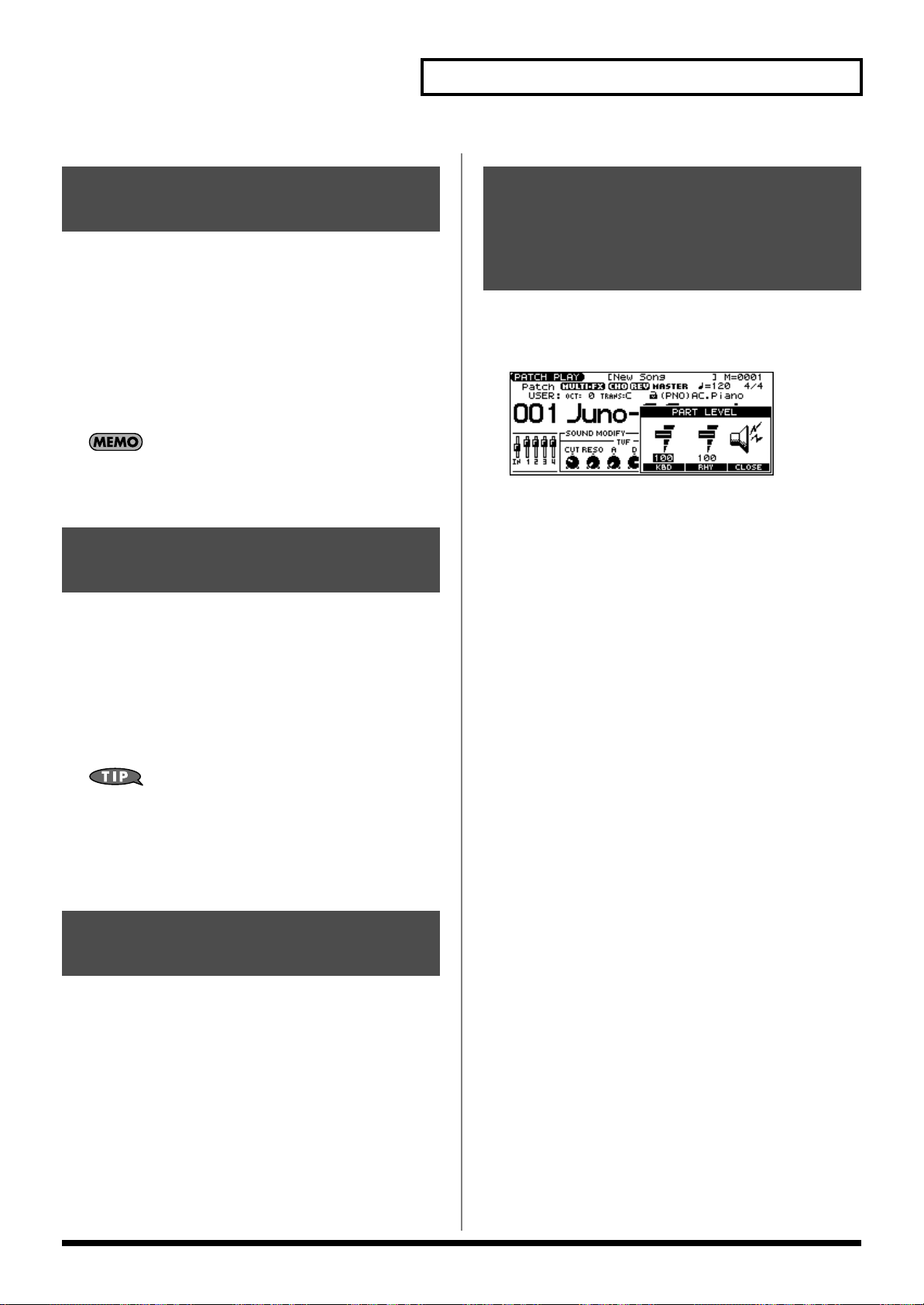
Playing in Patch Mode
Transposing the Keyboard in Semitone Steps (Transpose)
Transpose changes keyboard pitch in units of semitones.
This function is useful when you play transposed instruments such
as trumpet or clarinet following a printed score.
1.
In the PATCH PLAY screen, hold down [TRANSPOSE] and
press [-] or [+] to specify the amount of transposition (G–
F#: -5–+6 semitones).
• [TRANSPOSE] will light if the setting is anything other than C.
• Hold down [TRANSPOSE] and press both buttons
simultaneously to return the setting to C.
There is a single Transpose setting (Setup parameter) for the
entire JUNO-G. The changed setting will be remembered even if
you switch patches or performances.
Selecting the Tones That Will Sound (Tone On/Off)
Since a patch is a combination of up to four tones, you can switch
unwanted (tones out of the four) off and get just the sound of a
specific tone.
Adjusting the Volume Balance between the Keyboard Performance and the Rhythm Pattern
In the PATCH PLAY screen, hold down [SHIFT] and press
1.
[F4 (LEVEL)].
The PART LEVEL window appears.
Press [F4 (KBD)] (keyboard) or [F5 (PTN)] (rhythm pattern)
2.
to select a part.
3.
Use the VALUE dial or [INC] [DEC] to adjust the volume.
4.
Press [F6 (CLOSE)] to close the window.
1.
In the PATCH PLAY screen, press [TONE SW/SEL] so the
button is lit.
2.
Use SWITCH [1]–[4] to turn each tone on/off.
Making the button light turns the tone on.
If you want just one or two tones to sound in a patch, turn the
others off and store that setting on a patch. This cuts
nonessential use of the JUNO-G’s simultaneous voices.
Press [TONE SW/SEL] once again so its illumination is
3.
turned off.
Playing Percussion Instruments
In Patch mode, you can play percussion instruments from the
keyboard by selecting a rhythm set. As the rhythm tone assigned to
each key varies by the rhythm set selected, you can play a wide
range of percussion instruments.
29
Page 30
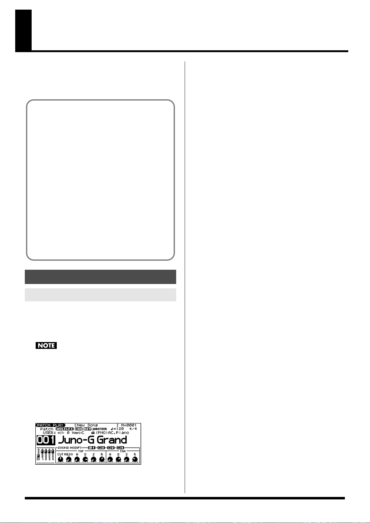
Creating a Patch
Four Tips for Editing Patches
Select a patch that is similar to the sound you wish to
create
With the JUNO-G, you have total control over a wide variety of
settings. Each item that can be set is known as a
you change the values of parameters, you are doing what is referred
to as
Editing
. This chapter explains the procedures used in creating
patches, and the functions of the patch parameters.
(p. 26)
It’s hard to create a new sound that’s exactly what you
want if you just select a patch and modify its parameters at
random. It makes sense to start with a patch whose sound
is related to what you have in mind.
Decide which tones will sound (p. 29)
Since a patch is a combination of up to any four tones, you
should listen to how the individual tones sound before you
edit. Then decide which tones you are going to use. It is
important to turn off unused tones to avoid wasting voices,
unnecessarily reducing the number of simultaneous notes
you can play.
Check the Structure setting (p. 35)
The important Structure parameter determines how the
four tones combine. Before you select new tones, make
sure you understand how the currently selected tones are
affecting each other.
Turn Effects off (p. 125)
Since you will hear the original sound of the patch itself
when the effects are turned off, the results of your
modifications will be easier to hear. Actually, sometimes just
changing effects settings can give you the sound you want.
parameter
. When
How to Make Patch Settings
Using the Knobs to Edit the Sound
You can use the six SOUND MODIFY knobs to edit the sound in real time.
Press MODE [PATCH] to access the PATCH PLAY screen.
1.
2.
Select the patch whose settings you want to edit (p. 26).
Changing the brightness of the sound and
adding special qualities (CUTOFF/RESONANCE)
The sound generator section of the JUNO-G contains a filter that can
cut or boost specific frequency regions of the sound. The CUTOFF
knob specifies the frequency (cutoff frequency) at which the filter
will begin to modify the sound, and the RESONANCE knob boosts
the region near the cutoff frequency to add a distinctive character to
the sound.
5.
Turn the CUTOFF or RESONANCE knobs.
Turning a knob toward the right increases the value.
FREQ:
Frequency at which the filter begins to have an effect on
the waveform’s frequency components
RESO:
Emphasizes the portion of the sound in the region of the
cutoff frequency, adding character to the sound
* Excessively high settings can produce oscillation, causing the sound to
distort.
Editing the way that the volume will change
The volume continues to change from the time a key is pressed to
when it is released.
6.
Press the SOUND MODIFY select button to make AMP ENV
light.
7.
Turn the ATTACK, DECAY, SUSTAIN, and RELEASE knobs.
Turning a knob toward the right increases the value.
A:
Attack Time: The time from when the keyboard is pressed
until the maximum tonal change is reached.
D:
Delay Time: The time from when the maximum tonal change
is reached until the Sustain Level is reached.
S:
Sustain level: Volume that is sustained while you hold down
the key
R:
Release Time: The time from when the keyboard is released
until the sound disappears.
* If you press the SOUND MODIFY select button so all of the
indicators are off, turning these knobs will not produce any change.
You cannot edit the patches in the GM2 group.
Selecting the tone to edit
3.
In the PATCH PLAY screen, press [TONE SW/SEL] so the
button is lit.
4.
Press SELECT[1]–[4] to select the tone(s) you want to edit.
In the SOUND MODIFY 1–4 area at the bottom of the screen, a
check mark (✔) will be added to the tone number(s) you select.
fig.PatchPlay
* You can press multiple buttons simultaneously to select multiple tones.
* By turning TONE SWITCH on/off you can edit the sound while
hearing only the desired tone.
30
Editing the way that tone (brightness) will
change
The tone undergoes changes between the moment you press a key
until you release it.
Press the SOUND MODIFY select button to make FILTER
8.
ENV light.
9.
Turn the ATTACK, DECAY, SUSTAIN, and RELEASE knobs.
Turning a knob toward the right increases the value.
* If you press the SOUND MODIFY select button so all of the
indicators are off, turning these knobs will not produce any change.
Applying vibrato, wah, or tremolo (LFO)
The LFO, short for “low frequency oscillator,” makes changes to the
sound in periodic fashion. Vibrato is the effect produced by using
the LFO to vary the pitch. Wah is the effect produced by using the
LFO to vary the cutoff frequency. Tremolo is the effect produced by
using the LFO to vary the volume.
Page 31

Creating a Patch
Press the SOUND MODIFY select button to make LFO light.
10.
11.
Turn the ATTACK, DECAY, SUSTAIN, and RELEASE knobs.
RATE:
LFO RATE: Speed of LFO 1
PIT:
LFO Pitch Depth: Depth by which LFO 1 changes the WG
pitch
FLT:
LFO TVF Depth: Depth by which LFO 1 changes the TVF
cutoff frequency
AMP:
LFO TVA Depth: Depth by which LFO 1 changes the
volume
For details on these parameters, refer to
Output
(p. 46).
* If you press the SOUND MODIFY select button so all of the
indicators are off, turning these knobs will not produce any change.
Modulating Sounds/
Editing in a Graphic Display (Zoom Edit)
The important parameters most commonly used to edit the sound
are available in eight screens for graphic editing.
Parameter page Parameter page
PITCH ENVELOPE p. 40 PATCH EDIT p. 35
TVF PARAMETER p. 40 LFO 1/2 p. 46
TVF ENVELOPE p. 41 STEP LFO p. 47
TVA ENVELOPE p. 43
1
2
3
1.
Graphic display
2.
Move the cursor and use the VALUE dial or [INC] [DEC]
3.
Corresponds to SOUND MODIFY knobs 1--4.
Press [WRITE] to save the changes you’ve made (p. 32).
8.
If you do not wish to save changes, press [EXIT] to return to
the PATCH PLAY screen.
If you return to the PATCH PLAY screen without saving, an “*”
will be displayed at the left of the rhythm set group.
If you turn off the power or select a different sound while the
display indicates “*,” your edited rhythm set will be lost.
Viewing and editing all parameters (PRO EDIT)
For details on the parameters, refer to p. 34 and follows.
1.
Press MODE [PATCH] to access the PATCH PLAY screen.
2.
Select the patch whose settings you want to edit (p. 26).
You cannot edit the patches in the GM2 group.
Press EDIT [PATCH] so it’s lit.
3.
4.
Press [F6 (PRO EDIT)].
5.
Use [F2 (GRP ↑)] [F3 (GRP ↓)] to switch the parameter group.
* Pressing [F1 (GRP LIST)] will display the Patch Pro Edit Menu
window. Use the VALUE dial or [INC] [DEC] [ ] [ ] to select a
parameter group, and press [ENTER].
Use [ ] [ ] to select a parameter.
6.
* A check mark (✔) will be added to the tone number in the upper right
of the screen.
Press MODE [PATCH] to access the PATCH PLAY screen.
1.
2.
Select the patch whose settings you want to edit (p. 26).
You cannot edit the patches in the GM2 group.
Press EDIT [PATCH] so it’s lit.
3.
4.
Use [F1]–[F4] to select the parameter screen.
* Pressing [F5 (PAGE)] will switch the [F1]–[F4] screens.
Use [ ] [ ] [ ] [ ] to select a parameter.
5.
* Some parameters can be edited independently for each tone. To select
the tone to edit, press [TONE SW/SEL] so it’s lit, and press one of the
SELECT [1]–[4] buttons.
6.
Use the VALUE dial or [INC] [DEC] to change the value.
Parameters with an indication of 1–4 can also be edited using
the corresponding SOUND MODIFY knob 1–4.
7.
Repeat steps 4–6 to set each parameter.
7.
Use the VALUE dial or [INC] [DEC] to change the value.
Parameters with an indication of 1–4 can also be edited using
the corresponding SOUND MODIFY knob 1–4.
8.
Repeat steps 5–7 to set each parameter.
9.
Press [WRITE] to save the changes you’ve made (p. 32).
If you do not wish to save changes, press [EXIT] to return to
the PATCH PLAY screen.
If you return to the PATCH PLAY screen without saving, an “*”
will be displayed at the left of the rhythm set group.
If you turn off the power or select a different sound while the
display indicates “*,” your edited rhythm set will be lost.
31
Page 32

Creating a Patch
Using the SOUND MODIFY Knobs to Change the Value
If a number is displayed for the parameter name (1, 2, 3, 4), you can
use the SOUND MODIFY knobs 1–4 to set the value.
* Press the SOUND MODIFY select button so all of the indicators are
off. If any indicator is lit, the knob functions will change.
For example, in the TVF ENVELOPE ZOOM screen, the knobs
correspond to parameters as follows.
Knob 1
Knob 2 D (Time 3)
Knob 3 S (Level 3)
Knob 4 R (Time 4)
A (Time 1)
Press [F6 (EXEC)] to execute the copy operation.
5.
* To cancel, press [F5 (CANCEL)].
The Compare Function
For the Patch Tone Copy and Patch Save operations, you can
use the Compare function.
If you want to play the copy-source or write-destination patch,
press [F4 (COMPR)] to add a check mark (✔). Now you can
play the copy-source or write-destination patch from the
keyboard.
* The patch auditioned using the Compare function may sound
slightly different than when it is played normally.
Saving Patches You’ve
Initializing Patch Settings
“Initialize” means to return the settings of the currently selected
sound to a standard set of values.
* The Initialize operation will affect only the currently selected sound;
the sounds that are stored in user memory will not be affected. If you
wish to restore all of the JUNO-G’s settings to their factory values,
perform a Factory Reset (p. 164).
1.
With EDIT [PATCH] lit, hold down [SHIFT] and press [F5 (INIT)].
A message will ask you for confirmation.
2.
Press [F6 (EXEC)].
The initialization will be carried out.
* To cancel, press [F5 (CANCEL)].
Copying Patch (Tone) Settings
This operation copies the settings of any desired patch to the
currently selected patch.
With EDIT [PATCH] lit, hold down [SHIFT] and press [F6
1.
(TONE COPY)].
The Patch Tone Copy window appears.
Created (Write)
Changes you make to sound settings are temporary, and will be lost
if you turn off the power or select another sound. If you want to keep
the modified sound, you must save it in the internal USER group
(user memory) or CARD group (memory card).
When you edit the patch settings, an “*” will appear in the PATCH
PLAY screen.
When you perform the save procedure, the data that previously
occupied the save destination will be lost.
Edit the patch.
1.
2.
Press EDIT [WRITE].
The WRITE MENU screen appears.
3.
Press [F2 (PAT/RHY)].
* Alternatively, you can use [ ] [ ] to select “Patch/Rhythm,” and
then press [ENTER].
The PATCH NAME screen appears.
Press [ ] [ ] [ ] [ ] to move the cursor, and use the
2.
VALUE dial or [INC] [DEC] to select the “Source (copysource)” group and number, and the tone.
* By pressing [F4 (COMPR)] to add a check mark (✔), you can check
the copy-source patch (Compare function).
Press [ ] [ ] [ ] [ ] to move the cursor, and select the
3.
“Destination (copy-destination)” tone.
Press [F6 (EXEC)].
4.
A message will ask you for confirmation.
32
Assign a name to the patch.
4.
For details on assigning names, refer to p. 24.
5.
When you have finished inputting the name, press [F6
(WRITE)].
A screen will appear, allowing you to select the write-
destination patch.
Page 33

6.
Use the VALUE dial, [INC] [DEC], or [ ] [ ] and [F1 (USER)]
[F2 (CARD)] to select the write destination and patch number.
* By pressing [F4 (COMPR)] to add a check mark (✔), you can check
the write-destination patch (Compare function).
7.
Press [F6 (WRITE)].
A message will ask you for confirmation.
Press [F6 (EXEC)] to execute the save operation.
8.
* To cancel, press [F5 (CANCEL)].
Never switch off the JUNO-G while data is being saved.
Creating a Patch
Tips for Using an Acoustic Instrument’s
Waveform
With many acoustic instruments such as piano and sax, extreme
timbral changes occur during the first few moments of each note.
This initial attack is what defines much of the instrument’s character.
For such waveforms, it is best to use the complex tonal changes of
the attack portion of the waveform just as they are, and to use the
envelope only to modify the decay portion.
fig.06-006.e
Level
Looped portion
Tone change stored
with the wave
One-shot Waveform and Loop
Waveform
The internal waveforms of the JUNO-G fall into the following two
groups.
One-shot:
These waveforms contain sounds that have short decays. A one-shot
waveform records the initial rise and fall of the sound.
The JUNO-G also contains many other one-shot waveforms that are
elements of other sounds. These include attack components such as
piano-hammer sounds and guitar fret noises.
* It is not possible to use the envelope to modify a one-shot waveform to
create a decay that is longer than the original waveform, or to turn it
into a sustaining sound.
Loop:
These waveforms include sounds with long decays as well as
sustained sounds. Loop waveforms repeatedly play back (loop) the
portion of the waveform after the sound has reached a relatively
steady state.
The JUNO-G’s looped waveforms also include components of other
sounds, such as piano-string resonant vibrations and the hollow
sounds of brass instruments.
The following diagram shows an example of sound (electric organ)
that combines one-shot and looped waveforms.
fig.06-005.e
TVA ENV for looped Organ
waveform (sustain portion)
Level
TVA ENV for one-shot Key
-click waveform (attack portion)
Resulting TVA ENV
change
Time
Envelope
for the TVF filter
Resulting
tone change
Note off
+=
Time
Note off
33
Page 34

Creating a Patch
1
2
3
OFF
2
1
OFF
3
High note range
Pitch difference from
equal temperament
Parameter value
Low note range
Functions of Patch Parameters
Settings Common to the Entire Patch
GENERAL
Parameter marked with a “★” can be controlled using specified MIDI messages
(Matrix Control, p. 44)
Parameter Value Description
Patch Category Refer to p. 26. Type (category) of the patch
Patch Level 0–127 Volume of the patch
Patch Pan L64–0–63R Left/right position of the patch
Patch Priority LAST, LOUDEST How notes will be managed when the maximum polyphony is exceeded (128 voices)
Octave Shift -3– +3 Pitch of the patch’s sound (in units of an octave)
Patch Coarse Tune
Patch Fine Tune -50– +50 Pitch of the patch’s sound (in 1-cent steps; one cent is 1/100th of a semitone)
Stretch Tune Depth OFF, 1–3 Stretched tuning (a system by which acoustic pianos are normally tuned, causing the lower range to be lower and the
Analog Feel 0–127 Depth of 1/f modulation (a pleasant and naturally-occurring ratio of modulation that occurs in a babbling brook or
Stretched Tuning
fig.06-011.e
★
-48– +48
LAST:
The last-played voices will be given priority (Notes will be turned off in order, beginning with the first-
played note.)
LOUDEST:
voice.)
Pitch of the patch’s sound (in semitones, +/- 4 octaves)
higher range to be higher than the mathematical tuning ratios would otherwise dictate)
OFF:
1–3:
rustling wind)
* You can simulate the natural instability characteristic of an analog synthesizer by adding this “1/f modulation.”
The loudest voices will be given priority (Notes will be turned off, beginning with the lowest-volume
Equal temperament
Higher settings will produce the greater difference in the pitch of the low and high ranges.
34
Page 35

Changing How a Tone Is Sounded (Structure)
TONE 1 (3)
TONE 2 (4)
TVA TVF
WG
WG
TVF TVA
R
TYPE 5
TONE 1 (3)
TONE 2 (4)
TVA TVF
WG
WG
TVF TVA
R
TYPE 6
Parameter
Struct 1 & 2, 3 & 4
(Structure Type)
Value Explanation
TYPE 01–TYPE 10 Determines how tone 1 and 2, or tone 3 and 4 are connected.
Creating a Patch
The following 10 different Types of combination are available.
TYPE 1
TONE 1 (3)
TONE 2 (4)
With this type, tones 1 and 2 (or 3 and 4) are independent. Use this type when
you want to preserve PCM sounds or create and combine sounds for each tone.
TYPE 3
TONE 1 (3)
TONE 2 (4)
This type mixes the sound of tone 1 (3) and tone 2 (4), applies a filter, and then
applies a booster to distort the waveform.
This type uses a ring modulator to create new overtones, and combines the two
filters. The tone 1 (3) TVA will control the volume balance of the two tones, adjusting the depth of ring modulator.
WG
WG
WG
WG
TVATVF
TVF TVA
TVA TVF
B
TVF TVA
TYPE 2
TONE 1 (3)
TONE 2 (4)
This type stacks the two filters together to intensify the characteristics of the filters. The TVA for tone 1 (or 3) controls the volume balance between the two
tones.
TYPE 4
TONE 1 (3)
TONE 2 (4)
This type applies a booster to distort the waveform, and then combines the two
filters. The TVA for tone 1 (or 3) controls the volume balance between the two
tones and adjusts booster level.
This type uses a ring modulator to create new overtones, and in addition mixes
in the sound of tone 2 (4) and stacks the two filters. Since the ring-modulated
sound can be mixed with tone 2 (4), tone 1 (3) TVA can adjust the amount of the
ring-modulated sound.
WG
TVA
WG
WG
TVA TVF
WG
TVF
TVF TVA
B
TVF TVA
TYPE 7
TONE 1 (3)
TONE 2 (4)
This type applies a filter to tone 1 (3) and ring-modulates it with tone 2 (4) to create new overtones.
TYPE 9
TONE 1 (3)
TONE 2 (4)
This type passes the filtered sound of each tone through a ring modulator to create new overtones. The tone 1 (3) TVA will control the volume balance of the two
tones, adjusting the depth of ring modulator.
WG
WG
WG
WG
TVATVF
R
TVATVF
TVF TVA
TVF TVA
R
TYPE 8
TONE 1 (3)
TONE 2 (4)
This type sends the filtered tone 1 (3) and tone 2 (4) through a ring modulator,
and then mixes in the sound of tone 2 (4) and applies a filter to the result.
TYPE 10
TONE 1 (3)
TONE 2 (4)
This type passes the filtered sound of each tone through a ring modulator to create new overtones, and also mixes in the sound of tone 2 (4). Since the ring-modulated sound can be mixed with tone 2 (4), tone 1 (3) TVA can adjust the amount
of the ring-modulated sound.
WG
WG
WG
WG
TVATVF
R
TVATVF
TVF TVA
TVF TVA
R
* When TYPE 2–10 is selected and one tone of a pair is turned off, the other tone will be sounded as TYPE 1 regardless of the displayed setting.
* If you limit the keyboard area in which a tone will sound (Keyboard Range, p. 37) or limit the range of velocities for which it will sound (Velocity Range, p.
38), the result in areas or ranges where the tone does not sound is just as if the tone had been turned off. This means that if TYPE 2–10 is selected and you
create a keyboard area or velocity range in which one tone of a pair does not sound, notes played in that area or range will be sounded by the other tone as
TYPE 1 regardless of the displayed setting.
35
Page 36

Creating a Patch
Booster
fig.Boost1.e
The Booster is used to distort the incoming signal.
Booster level
TVA
WG1
WG2
Booster
Adds to WG1
Shift in waveform by WG1
Distorted area of the
Waveform changes
WG2
Uses WG1 as LFO
Adjusts WG1 output
Parameter
Booster 1&2, 3&4
(Booster Gain)
fig.Boost2.e
In addition to using this to create distortion, you can use the waveform
Value Explanation
0, +6, +12, +18 When a Structure Type of TYPE 3 or TYPE 4 is selected, you can adjust the depth of the booster. The booster increases the
input signal in order to distort the sound. This creates the distortion effect frequently used with electric guitars. Higher settings will produce more distortion.
(WG1) of one of the tones as an LFO which shifts the other waveform
(WG2) upward or downward to create modulation similar to PWM (pulse
width modulation). This parameter works best when you use it in
conjunction with the Wave Gain parameter (p. 38).
Ring Modulator
fig.RingMod
A ring modulator multiplies the waveforms of two tones with each other,
generating many new overtones (in harmonic partials) which were not
present in either waveform. (Unless one of the waveforms is a sine wave,
evenly-spaced frequency components will not usually be generated.)
As the pitch difference between the two waveforms changes the harmonic
structure, the result will be an unpitched metallic sound. This function is
suitable for creating metallic sounds such as bells.
MODIFY
These values are added to the parameter values of each tone.
Parameter
Cutoff Offset
Resonance Offset -63– +63 Resonance (p. 40)
Attack Time Offset -63– +63 F-Env Time 1, A-Env Time 1 (p. 41, p. 43)
Release Time Offset -63– +63 F-Env Time 4, A-Env Time 4 (p. 41, p. 43)
Velocity Sens Offset -63– +63 Cutoff V-Sens, Level V-Sens (p. 41, p. 42)
Value Description
-63– +63 Cutoff Frequency (p. 40)
36
Page 37

PORTAMENTO
Portamento is an effect which smoothly changes the pitch from the first-played key to the next-played key.
Parameter
Portamento Switch
Portamento Mode NORMAL, LEGATO
Portamento Type RATE, TIME
Portamento Start PITCH, NOTE
Portamento Time 0–127 Specifies the time over which the pitch will change.
fig.PortaStart.e
Pitch
Value Explanation
OFF, ON Specifies whether the portamento effect will be applied (ON) or not (OFF).
NORMAL:
LEGATO:
RATE:
TIME:
PITCH:
NOTE:
Portamento will always be applied.
Portamento will be applied only when you play legato.
The time it takes will depend on the distance between the two pitches.
The time it takes will be constant, regardless of how far apart in pitch the notes are.
Starts a new portamento when another key is pressed while the pitch is changing.
Portamento will begin anew from the pitch where the current change would end.
Portamento Start: NOTEPortamento Start: PITCH
Pitch
Creating a Patch
C5
D4
C4
press D4 key
press C5 key
press C4 key
C5
D4
C4
Time
press D4 key
press C5 key
press C4 key
CONTROL
Parameter
Mono/Poly
Legato Switch OFF, ON
Legato Retrigger
Pitch Bend Range Up 0– +48 Degree of pitch change in semitones when the Pitch Bend lever is all the way right
Pitch Bend Range Down -48–0 Degree of pitch change in semitones when the Pitch Bend lever is all the way left
Value Explanation
MONO, POLY
OFF, ON
MONO:
Only the last-played note will sound. This setting is effective when playing a solo instrument patch
such as sax or flute.
POLY:
Two or more notes can be played simultaneously.
ON:
Pressing a key while continuing to press a previous key causes the note to change pitch to the pitch of the
most recently pressed key, sounding all the while. This is effective when you wish to simulate the hammeringon and pulling-off techniques used by a guitarist.
* Legato Switch is valid when the Mono/Poly parameter is set to “MONO.”
OFF:
When one key is held down and another key is then pressed, only the pitch changes, without the attack
of the latter key being played. Set this to “OFF” when performing wind and string phrases or when using modulation with the mono synth keyboard sound.
ON:
Normally you will leave this parameter “ON.”
* Legato Retrigger is valid when the Mono/Poly is set to “MONO” and the Legato Switch is set to “ON.”
Time
KEY RANGE
You can use the note number to control the way each Tone is played.
fig.TMT-K.e
Level
Key Fade Lower
Key Range Lower
Parameter
Key Fade Lower
Key Range Lower C - –(Upper) Specifies the lowest note that the tone will sound for each tone.
Key Range Upper (Lower)–G9 Specifies the highest note that the tone will sound for each tone.
Key Fade Upper 0–127 Determines what will happen to the tone’s level when a note that’s higher than Key Range Upper is played.
The tone sounded
in the lower range
Key Range Upper
Value Explanation
0–127 Determines what will happen to the tone’s level when a note that’s lower than Key Range Lower is played.
If you don’t want the tone to sound at all, set this parameter to “0.”
If you don’t want the tone to sound at all, set this parameter to “0.”
The tone sounded
in the upper range
Key Fade Upper
Pitch
37
Page 38

Creating a Patch
VELOCITY RANGE
You can use the force with which keys are played to control the way each Tone is played.
fig.TMT-V.e
Level
The tone sounded
when you play softly
The tone sounded
when you play strongly
Velocity
Velo Fade Lower
Velo Range Lower
Parameter
Tone Mix Velo Control
Control Switch OFF, ON Use the Matrix Control (p. 44) to enable (ON), or disable (OFF) sounding of different tones.
Velo Fade Lower 0–127 Determines what will happen to the tone’s level when the tone is played at a velocity lower than Velo Range Lower.
Velo Range Lower 1–(Upper) Specifies the lowest velocity at which the tone will sound.
Velo Range Upper (Lower)–127 Specifies the highest velocity at which the tone will sound.
Velo Fade Upper 0–127 Determines what will happen to the tone’s level when the tone is played at a velocity greater than Velo Range Upper.
Value Explanation
OFF, ON,
RANDOM,
CYCLE
Determines whether a different tone is played (ON) or not (OFF) depending on the force with which the key is played
(velocity).
Velo Fade Upper
Velo Range Upper
RANDOM:
CYCLE:
If you don’t want the tone to sound at all, set this parameter to “0.”
If you don’t want the tone to sound at all, set this parameter to “0.”
The patch’s constituent tones will sound randomly, regardless of any Velocity messages.
The patch’s constituent tones will sound consecutively, regardless of any Velocity messages.
When using the Matrix Control to have different tones played, set the lowest value (Lower) and highest value (Upper) of the value of the
MIDI message used.
Instead of using Velocity, you can also have tones substituted using the Matrix Control. However, the keyboard velocity and the Matrix
Control cannot be used simultaneously to make different tones to sound. When using the Matrix Control to switch tones, set the Tone Mix
Velo Control parameter to “OFF.”
Modifying Waveforms/Pitch/Pitch Envelope
WAVE PARAMETER
Parameter
Wave Group
Wave Bank PRST, USER,
Wave No. L (Mono)
Wave No. R
Wave Gain -6, 0, +6, +12 Gain (amplification) of the waveform
Wave Tempo Sync
Value Explanation
INT, EXP,
SAMP
CARD
----, 1–1267 Basic waveform for a tone (The upper limit will depend on the wave group.)
OFF, ON When you wish to synchronize a Phrase Loop to the clock (tempo), set this to “ON.”
Group for the waveform that is to be the basis of the tone
INT:
Waveforms stored in internal
EXP:
Waveform stored in a Wave Expansion Board (SRX series) installed in EXP slots
SAMP:
Sample waveforms
When the Wave Group is SAMP: PRST, USER, CARD
When the Wave Group is MSAM: USER, CARD
When in monaural mode, only the left side (L) is specified. When in stereo, the right side (R) is also specified.
If you want to select a left/right pair of Waves, select the left (L) Wave number, and then hold down [SHIFT] and
press [F4 (STEREO)] to add a check mark (✔); the right (R) (Wave) will be recalled.
The value changes in 6 dB (decibel) steps—an increase of 6 dB doubles the waveform’s gain.
* If you intend to use the Booster to distort the waveform’s sound, set this parameter to its maximum value (p. 36).
* This is valid only when a separately sold wave expansion board is installed, and a waveform that indicates a tempo (BPM) is
selected as the sample for a tone.
If a waveform from a wave expansion board is selected for the tone, turning the Wave Tempo Sync parameter “ON”
will cause pitch-related settings and FXM-related settings to be ignored.
• If a sample is selected for a tone, you must first set the BPM (tempo) parameter of the sample.
• If a sample is selected for a tone, Wave Tempo Sync will require twice the normal number of voices.
• When this parameter is set to “ON,” set the Tone Delay Time parameter (p. 45) to “0.”
38
Page 39

Creating a Patch
Phrase Loop
Phrase loop refers to the repeated playback of a phrase that’s
been pulled out of a song (e.g., by using a sampler). One
technique involving the use of Phrase Loops is the excerpting of
Realtime Time Stretch
If the wave group is “SAMP” or “MSAM,” and the Wave
Tempo Sync parameter is turned “ON,” you can vary the
playback speed of the waveform without affecting the pitch.
a Phrase from a pre-existing song in a certain genre, for example
dance music, and then creating a new song with that Phrase
used as the basic motif. This is referred to as “Break Beats.”
Parameter marked with a “★” can be controlled using specified MIDI messages
Parameter
FXM Switch
FXM Color 1–4 How FXM will perform frequency modulation
FXM Depth
★
Value Explanation
OFF, ON This sets whether FXM will be used (ON) or not (OFF).
Higher settings result in a grainier sound, while lower settings result in a more metallic sound.
0–16
Depth of the modulation produced by FXM
FXM
FXM (Frequency Cross Modulation) uses a specified waveform
to apply frequency modulation to the currently selected
waveform, creating complex overtones. This is useful for
creating dramatic sounds or sound effects.
(Matrix Control, p. 44)
WAVE PITCH
Parameter marked with a “★” can be controlled using specified MIDI messages
Parameter
Tone Coarse Tune
Tone Fine Tune
Rand Pitch Depth 0–1200 Width of random pitch deviation that will occur each time a key is pressed (in 1-cent steps)
Pitch Keyfollow -200– +200 Amount of pitch change that will occur when you play a key one octave higher
P-Env V-Sens -63– +63 Keyboard playing dynamics can be used to control the depth of the pitch envelope.
P-Env T1 V-Sens -63– +63 This allows keyboard dynamics to affect the T1 of the Pitch envelope.
P-Env T4 V-Sens -63– +63 Use this parameter when you want key release speed to affect the T4 value of the Pitch envelope.
P-Env Time KF
(Time Keyfollow)
Pitch
★
Value Explanation
★
-48– +48
-50– +50
-100– +100 Use this setting if you want the pitch envelope times (T2–T4) to be affected by the keyboard location.
Pitch Keyfollow
Pitch of the tone’s sound (in semitones, +/-4 octaves)
Pitch of the tone’s sound (in 1-cent steps; one cent is 1/100th of a semitone)
If you do not want the pitch to change randomly, set this to “0.”
If you want the pitch to rise one octave as on a conventional keyboard, set this to “+100.” If you want the pitch to rise
two octaves, set this to “+200.”
If you want the pitch envelope to have more effect for strongly played notes, set this parameter to a positive (+) value.
If you want T1 to be speeded up for strongly played notes, set this parameter to a positive (+) value.
If you want T4 to be speeded up for quickly released notes, set this parameter to a positive (+) value.
Based on the pitch envelope times for the C4 key, positive (+) settings will cause notes higher than C4 to have increasingly shorter times.
+200
Time
+100
+50
0
Time Keyfollow
(Matrix Control, p. 44)
-100
-50
0
C4C3C2C1 C5 C6 C7
-50
-100-200
Key
C4C3C2C1 C5 C6 C7
+50
+100
Key
39
Page 40

Creating a Patch
WAVE PITCH ENV
Parameter
P-Env Depth
P-Env Time 1–4
P-Env Level 0–4 -63– +63 Pitch envelope levels (L0–L4)
★
Pitch Envelope
Pitch
L0
Note on
Value Explanation
-12– +12 Depth of the Pitch envelope
0–127
T1 T2 T3 T4
L1
L2
Higher settings will cause the pitch envelope to produce greater change. Negative (-) settings will invert the shape of
the envelope.
Pitch envelope times (T1–T4)
Higher settings will result in a longer time until the next pitch is reached.
Specify how the pitch will change at each point, relative to the pitch set with Coarse Tune or Fine Tune.
L3
Note off
L4
Parameter marked with a “★” can be controlled using specified MIDI messages
(Matrix Control, p. 44)
Time
Modifying the Brightness of a Sound with a Filter (TVF/TVF Envelope)
A filter cuts or boosts a specific frequency region to change a sound’s brightness, thickness, or other qualities.
TVF PARAMETER
Parameter marked with a “★” can be controlled using specified MIDI messages
(Matrix Control, p. 44)
Parameter
Filter Type
Cutoff Frequency
Resonance
Cutoff Keyfollow
★
Value Explanation
OFF, LPF,
BPF, HPF,
PKG,
LPF2,
LPF3
★
0–127
0–127
-200– +200 Use this parameter if you want the cutoff frequency to change according to the key that is pressed.
Type of filter
OFF:
No filter is used.
LPF:
Low Pass Filter. This reduces the volume of all frequencies above the cutoff frequency in order to round off, or un-
brighten the sound.
BPF:
Band Pass Filter. This leaves only the frequencies in the region of the cutoff frequency, and cuts the rest. This can
be useful when creating distinctive sounds.
HPF:
High Pass Filter. This cuts the frequencies in the region below the cutoff frequency. This is suitable for creating
percussive sounds emphasizing their higher tones.
PKG:
Peaking Filter. This emphasizes the frequencies in the region of the cutoff frequency. You can use this to create
wah-wah effects by employing an LFO to change the cutoff frequency cyclically.
LPF2:
Low Pass Filter 2. Although frequency components above the Cutoff frequency are cut, the sensitivity of this filter
is half that of the LPF. This filter is good for use with simulated instrument sounds such as the acoustic piano.
LPF3:
Low Pass Filter 3. Although frequency components above the Cutoff frequency are cut, the sensitivity of this filter
changes according to the Cutoff frequency. While this filter is also good for use with simulated acoustic instrument
sounds, the nuance it exhibits differs from that of the LPF2, even with the same TVF Envelope settings.
* If you set “LPF2” or “LPF3,” the setting for the Resonance parameter will be ignored.
Frequency at which the filter begins to have an effect on the waveform’s frequency components
Emphasizes the portion of the sound in the region of the cutoff frequency, adding character to the sound
* Excessively high settings can produce oscillation, causing the sound to distort.
Relative to the cutoff frequency at the C4 key (center C), positive (+) settings will cause the cutoff frequency to rise for
notes higher than C4, and negative (-) settings will cause the cutoff frequency to fall for notes higher than C4. Larger
settings will produce greater change.
40
Page 41

Creating a Patch
1234567
Level
High
Cutoff frequency
parameter value
Low
Parameter
Cutoff V-Curve
LPF BPF
Frequency
Value Explanation
FIX, 1–7 Curve that determines how keyboard playing dynamics (velocity) will affect the cutoff frequency
Resonance
HPF PKG
Set this to “FIX” if you don’t want the Cutoff frequency to be affected by the keyboard velocity.
Cutoff frequency
(Octave)
+2
+1
o
-1
-2
Cutoff Keyfollow
C4C3C2C1 C5 C6 C7
+200
+100
+50
0
-50
-100-200
Key
1234567
Cutoff V-Sens -63– +63 Use this parameter when changing the cutoff frequency to be applied as a result of changes in playing velocity. If you want
Resonance V-Sens -63– +63 This allows keyboard velocity to modify the amount of Resonance.
F-Env V-Curve FIX, 1–7 Curve that determines how keyboard playing dynamics (velocity) will affect the TVF envelope
strongly played notes to raise the cutoff frequency, set this parameter to positive (+) settings.
If you want strongly played notes to have a greater Resonance effect, set this parameter to positive (+) settings.
Set this to “FIX” if you don’t want the TVF Envelope to be affected by the keyboard velocity.
F-Env V-Sens -63– +63 Specifies how keyboard playing dynamics will affect the depth of the TVF envelope.
F-Env T1 V-Sens -63– +63 This allows keyboard dynamics to affect the T1 of the TVF envelope.
F-Env T4 V-Sens -63– +63 Use this parameter when you want key release speed to affect the T4 value of the TVF envelope.
Positive (+) settings will cause the TVF envelope to have a greater effect for strongly played notes, and negative (-) settings will cause the effect to be less.
If you want T1 to be speeded up for strongly played notes, set this parameter to a positive (+) value.
If you want T4 to be speeded up for quickly released notes, set this parameter to a positive (+) value.
TVF ENVELOPE
Parameter marked with a “★” can be controlled using specified MIDI messages
Parameter Value Explanation
F-Env Depth -63– +63 Depth of the TVF envelope
F-Env Time KF
(Time Keyfollow)
F-Env Time 1–4
F-Env Level 0–4 0–127 TVF envelope levels (L0–L4)
★
-100– +100 Use this setting if you want the TVF envelope times (T2–T4) to be affected by the keyboard location.
0–127
Higher settings will cause the TVF envelope to produce greater change. Negative (-) settings will invert the shape of the
envelope.
Based on the TVF envelope times for the C4 key (center C), positive (+) settings will cause notes higher than C4 to have
increasingly shorter times.
TVF envelope times (T1–T4)
Higher settings will lengthen the time until the next cutoff frequency level is reached.
Specify how the cutoff frequency will change at each point, relative to the Cutoff Frequency value.
(Matrix Control, p. 44)
41
Page 42

Creating a Patch
1234567
Cutoff
Frequency
TVF Envelope
T1 T2 T3 T4
L0
L1
Note on
L3
L2 L4
Time
Note off
Time Time Keyfollow
C4C3C2C1 C5 C6 C7
Adjusting the Volume (TVA/TVA Envelope)
TVA PARAMETER
Parameter marked with a “★” can be controlled using specified MIDI messages
Parameter Value Explanation
Tone Level
Level V-Curve FIX, 1–7 Curve that determines how keyboard playing dynamics (velocity) will affect the volume
★
0–127 Volume of the tone.
This setting is useful primarily for adjusting the volume balance between tones.
Set this to “FIX” if you don’t want the volume of the tone to be affected by the keyboard velocity.
-100
-50
0
+50
+100
Key
(Matrix Control, p. 44)
Level V-Sens -63– +63 Set this when you want the volume of the tone to change depending on keyboard playing dynamics.
Bias
Bias Level -100– +100 Angle of the volume change that will occur in the selected Bias Direction
Bias Position C - –G9 Key relative to which the volume will be modified
Bias Direction LWR, UPR,
Bias causes the volume to be affected by the keyboard position. This is useful for changing volume through keyboard position (pitch) when
playing acoustic instruments.
L&U, ALL
LWR
Level
Parameter Value Explanation
Tone Pan
Pan Keyfollow -100– +100 Use this parameter if you want key position to affect panning.
+
0
–
C-1 G9
Bias Position
★
L64–0–63R Left/right position of the tone
Set this to a positive (+) value to have the changes in tone volume increase the more forcefully the keys are played; to
make the tone play more softly as you play harder, set this to a negative (-) value.
Larger settings will produce greater change. Negative (-) values will invert the change direction.
Direction in which change will occur starting from the Bias Position
LWR:
The volume will be modified for the keyboard area below the Bias Point.
UPR:
The volume will be modified for the keyboard area above the Bias Point.
L&U:
The volume will be modified symmetrically toward the left and right of the Bias Point.
ALL:
The volume changes linearly with the bias point at the center.
UPR
Level
Key
C-1 G9
Bias Position
Positive (+) settings will cause notes higher than C4 key (center C) to be panned increasingly further toward the right,
and negative (-) settings will cause notes higher than C4 key (center C) to be panned toward the left. Larger settings
will produce greater change.
L&U
+
Level
0
–
Key
+
0
–
C-1 G9
Bias Position
ALL
+
Level
0
–
Key
–
0
+
C-1 G9
Bias Position
+
0
–
Key
42
Page 43

Pan Pan Keyfollow
R
Creating a Patch
+100
+50
o
L
Parameter Value Explanation
Random Pan Depth 0–63 Use this parameter when you want the stereo location to change randomly each time you press a key.
Alter Pan Depth L63–0–63R This setting causes panning to be alternated between left and right each time a key is pressed.
C4C3C2C1 C5 C6 C7
Higher settings will produce a greater amount of change.
Higher settings will produce a greater amount of change. “L” or “R” settings will reverse the order in which the pan
will alternate between left and right. For example if two tones are set to “L” and “R” respectively, the panning of the
two tones will alternate each time they are played.
* When any value from Type “2”–”10” is selected for the Structure parameter in the Pan KF, Rnd Pan Depth, Alter Pan Depth
parameter settings, the output of tones 1 and 2 are joined in tone 2, and the output of tones 3 and 4 are joined in tone 4. For this
reason, tone 1 will follow the settings of tone 2, and tone 3 will follow the settings of tone 4 (p. 35).
0
-50
-100
Key
TVA ENVELOPE
Parameter marked with a “★” can be controlled using specified MIDI messages
(Matrix Control, p. 44)
Parameter
A-Env T1 V-Sens
A-Env T4 V-Sens -63– +63 Use this parameter when you want key release speed to affect the T4 value of the TVA envelope.
A-Env Time KF
(Time Keyfollow)
A-Env Time 1–4
A-Env Level 1–3 0–127 TVA envelope levels (L1–L3)
★
Value Explanation
-63– +63 This allows keyboard dynamics to affect the T1 of the TVA envelope.
-100– +100 Use this setting if you want the TVA envelope times (T2–T4) to be affected by the keyboard location. Based on
0–127
If you want Time 1 to be speeded up for strongly played notes, set this parameter to a positive (+) value. If you
want it to be slowed down, set this to a negative (-) value.
If you want T4 to be speeded up for quickly released notes, set this parameter to a positive (+) value. If you
want it to be slowed down, set this to a negative (-) value.
the TVA envelope times for the C4 key (center C), positive (+) settings will cause notes higher than C4 to have
increasingly shorter times, and negative (-) settings will cause them to have increasingly longer times. Larger set-
tings will produce greater change.
TVA envelope times (T1–T4)
Higher settings will lengthen the time until the next volume level is reached.
Specify how the volume will change at each point, relative to the Tone Level value.
TVA Envelope
Level
Note on
T1 T2 T3 T4
L2
L1
L3
Note off
Time
Time
Time Keyfollow
C4C3C2C1 C5 C6 C7
-100
-50
0
+50
+100
Key
43
Page 44

Creating a Patch
Matrix Control Settings/Miscellaneous Settings
MATRIX CTRL1–4
The function which allows you use MIDI messages to make changes in realtime to the tone parameters is called the
Matrix Controls can be used in a single patch.
To use the Matrix Control, specify which MIDI message (CTRL Source parameter) will be used to control which parameter (CTRL Destination
parameter), and how greatly (CTRL Sens parameter), and the tone to which the effect is applied (CTRL Switch parameter).
Parameter
CTRL 1–4 Source
Value Explanation
OFF, CC01–31, 33–95,
PITCH BEND,
AFTERTOUCH,
SYS CTRL1–4,
VELOCITY,
KEY FOLLOW, TEMPO,
LFO1, LFO2, PITCH
ENV, TVF ENV, TVA
ENV
MIDI message used to change the tone parameter with the Matrix Control
OFF:
Matrix control will not be used.
CC01–31, 33–95:
PITCH BEND:
SYS CTRL1–4:
VELOCITY:
TEMPO:
LFO1:
LFO 1
PITCH ENV:
Controller numbers 1–31, 33–95
Pitch Bend
MIDI messages used as common matrix controls
Pressure you press a key with
The specified tempo (song recorder tempo) or the tempo of an external MIDI sequencer.
LFO2:
Pitch envelope
AFTERTOUCH:
LFO 2
TVF ENV:
Aftertouch
KEY FOLLOW:
TVF envelope
Keyboard position with C4 as 0
TVA ENV:
Velocity and Key follow correspond to Note messages.
Matrix Control
TVA envelope
. Up to four
Although there are no MIDI messages for LFO 1 through TVA Envelope, they can be used as Matrix Control. In this case, you can change the
tone settings in realtime by playing patches.
• If you want to use common controllers for the entire JUNO-G, select “SYS CTRL1”–”SYS CTRL4.” MIDI messages used as System Control 1–
4 are set with the System Ctrl 1–4 Source parameters (p. 160).
There are parameters that determine whether or not Pitch Bend, Controller Number 11 (Expression) and Controller Number 64 (Hold 1) are
received (p. 45). When these settings are “ON,” and the MIDI messages are received, then when any change is made in the settings of the
desired parameter, the Pitch Bend, Expression, and Hold 1 settings also change simultaneously. If you want to change the targeted
parameters only, then set these to “OFF.”
• There are parameters that let you specify whether specific MIDI messages will be received for each channel in a performance (p. 67). When a
patch with Matrix Control settings is assigned to a part, confirm that any MIDI messages used for the Matrix Control will be received. If the
JUNO-G is set up such that reception of MIDI messages is disabled, then the Matrix Control will not function.
Parameter Value Explanation
CTRL 1–4
Destination 1–
4
OFF, PITCH, CUTOFF, RESONANCE, LEVEL, PAN,
OUTPUT LEVEL, CHORUS
SEND,
REVERB SEND,
LFO1/2 PITCH DEPTH,
LFO1/2 TVF DEPTH,
LFO1/2 TVA DEPTH,
LFO1/2 PAN DEPTH,
LFO1/2 RATE,
PCH ENV A-TIME,
PCH ENV D-TIME,
PCH ENV R-TIME,
TVF ENV A-TIME,
TVF ENV D-TIME,
TVF ENV R-TIME,
TVA ENV A-TIME,
TVA ENV D-TIME,
TVA ENV R-TIME, TMT,
FXM DEPTH, MFX CTRL1–
4, TIME
Tone parameter that is to be controlled when using the Matrix Control
Up to four parameters can be specified for each Matrix Control, and controlled simultaneously.
* In this manual, Parameters that can be controlled using the Matrix Control are marked with a “★.”
Parameter
CTRL 1–4 Sens 1–4
CTRL 1–4 Switch 1–4 OFF, ON,
Value Explanation
-63– +63 Amount of the Matrix Control’s effect that is applied
REVS
44
If you wish to modify the selected parameter in a positive (+) direction—i.e., a higher value, toward the right, or
faster etc.—from its current setting, select a positive (+) value. If you wish to modify the selected parameter in a negative (-) direction—i.e., a lower value, toward the left, or slower etc.—from its current setting, select a negative (-)
value. For either positive or negative settings, greater absolute values will allow greater amounts of change. Set this
to “0” if you don’t want to apply the effect.
Tone to which the effect is applied when using the Matrix Control
OFF:
The effect will not be applied.
ON:
The effect will be applied.
REVS:
The effect will be applied in reverse.
Page 45

Creating a Patch
Note off
Delay time
Note on
Tone Delay Mode: NORM
No Tone Delay
Note off
Delay time
Note on
Tone Delay Mode: HOLD
No sound
played
Note off
Delay time
Note on
Tone Delay Mode: OFFN
Note off
Delay time
Note on
Tone Delay Mode: OFFD
MISC
Tone Delay
This produces a time delay between the moment a key is pressed (or released), and the moment the tone actually begins to sound. You can also
make settings that shift the timing at which each tone is sounded. This differs from the Delay in the internal effects, in that by changing the sound
qualities of the delayed tones and changing the pitch for each tone, you can also perform arpeggio-like passages just by pressing one key.
You can also synchronize the tone delay time to the tempo of the song recorder.
* If you are not going to use Tone Delay, set the Delay Mode parameter to “NORM” and Delay Time parameter to “0.”
• If the Structure parameters set in the range of “2”–”10,” the output of tones 1 and 2 will be combined into tone 2, and the output of tones 3
and 4 will be combined into tone 4. For this reason, tone 1 will follow the settings of tone 2, and tone 3 will follow the settings of tone 4 (p. 35).
Parameter
Tone Delay Mode
Tone Delay Time
fig.ToneDly1.e
Value Explanation
NORM,
HOLD,
OFFN,
OFFD
0-127,
Note
Type of tone delay
NORM:
HOLD:
Although the tone begins to play after the time specified in the Delay Time parameter has elapsed, if the key is re-
leased before the time specified in the Delay Time parameter has elapsed, the tone is not played.
OFFN:
Rather than being played while the key is pressed, the tone begins to play once the period of time specified in the
Delay Time parameter has elapsed after release of the key. This is effective in situations such as when simulating noises
from guitars and other instruments.
OFFD:
Rather than being played while the key is pressed, the tone begins to play once the period of time specified in the
Delay Time parameter has elapsed after release of the key. Here, however, changes in the TVA Envelope begin while the
key is pressed, which in many cases means that only the sound from the release portion of the envelope is heard.
* If you have selected a waveform that is a decay-type sound (i.e., a sound that fades away naturally even if the key is not released), select-
ing “OFFN” or “OFFD” may result in no sound being heard.
Time from when the key is pressed (or if the Delay Mode parameter is set to “OFFN” or “OFFD,” the time from when the key
is released) until when the tone will sound
Tone Delay Time specifies the beat length for the synchronized tempo when the tempo that specifies the elapsed time until
the tone is sounded (Patch Tempo) is synchronized with the tempo set in a song recorder.
The tone begins to play after the time specified in the Delay Time parameter has elapsed.
Parameter
Tone Env Mode
Rx Bender
Rx Expression OFF, ON For each tone, specify whether MIDI Expression messages will be received (ON), or not (OFF).
Rx Hold-1 OFF, ON For each tone, specify whether MIDI Hold-1 messages will be received (ON), or not (OFF).
Rx Pan Mode
Redamper Sw
Value Explanation
NSUS,
SUST
OFF, ON For each tone, specify whether MIDI Pitch Bend messages will be received (ON), or not (OFF).
CONT, K-ONFor each tone, specify how pan messages will be received.
OFF, ON You can specify, on an individual tone basis, whether or not the sound will be held when a Hold 1 message is received after
When a loop waveform (p. 33) is selected, the sound will normally continue as long as the key is pressed. If you want the
sound to decay naturally even if the key remains pressed, set this to “NSUS.”
* If a one-shot type wave (p. 33) is selected, it will not sustain even if this parameter is set to “SUST.”
* If “NSUS” is selected for Env Mode parameter, this setting will have no effect.
CONT:
Whenever Pan messages are received, the stereo position of the tone will be changed.
K-ON:
The pan of the tone will be changed only when the next note is played. If a pan message is received while a note
is sounding, the panning will not change until the next key is pressed.
* The channels cannot be set so as not to receive Pan messages.
a key is released, but before the sound has decayed to silence.
If you want to sustain the sound, set this “ON.” When using this function, also set the Rx Hold-1 parameter “ON.” This
function is effective for piano sounds.
45
Page 46

Creating a Patch
Modulating Sounds/Output
An LFO (Low Frequency Oscillator) causes change over a cycle in a sound. Each tone has two LFOs (LFO1/LFO2), and these can be used to
cyclically change the pitch, cutoff frequency and volume to create modulation-type effects such as vibrato, wah and tremolo. Both LFOs have the
same parameters so only one explanation is needed.
LFO 1–2
Parameter marked with a “★” can be controlled using specified MIDI messages
(Matrix Control, p. 44)
Parameter
Wave Form
Rate
★
Rate Detune
Offset -100– +100 Raises or lowers the LFO waveform relative to the central value (pitch or cutoff frequency).
Delay Time 0–127 Time elapsed before the LFO effect is applied (the effect continues) after the key is pressed (or released)
Delay Time KF
(Time Keyfollow)
fig.T-KF.e
Time
Value Explanation
SIN,
TRI,
SAWU,
SAWD,
SQR,
RND, BDU, BD-D,
TRP, S&H,
CHS,
VSIN,
STEP
0–127,
Note
0–127 Makes subtle changes in the LFO cycle rate (Rate parameter) each time a key is pressed.
-100– +100 Adjusts the value for the Delay Time parameter depending on the key position, relative to the C4 key (center C).
Waveform of the LFO
SIN:
Sine wave
TRI:
Triangle wave
SAWU:
Sawtooth wave
SAWD:
Sawtooth wave (negative polarity)
SQR:
Square wave
RND:
Random wave
BD-U:
Once the attack of the waveform output by the LFO is allowed to develop in standard fashion, the waveform then con-
tinues without further change.
BD-D:
Once the decay of the waveform output by the LFO is allowed to develop in standard fashion, the waveform then con-
tinues without further change.
TRP:
Trapezoidal wave
S&H:
Sample & Hold wave (one time per cycle, LFO value is changed)
CHS:
Chaos wave
VSIN:
Modified sine wave. The amplitude of a sine wave is randomly varied once each cycle.
STEP:
A waveform generated by the data specified by LFO Step 1–16. This produces stepped change with a fixed pattern sim-
ilar to a step modulator.
* If you set this to “BD-U” or “BD-D,” you must turn the Key Trigger parameter to “ON.” If this is “OFF,” it will have no effect.
Modulation speed of the LFO
LFO Rate sets the beat length for the synchronized tempo is synchronized with the tempo set in a sequencer.
* This setting will be ignored if the Waveform parameter is set to “CHAOS.”
Higher settings will cause greater change. This parameter is invalid when Rate is set to “note.”
Positive (+) settings will move the waveform so that modulation will occur from the central value upward. Negative (-) settings will move the waveform so that modulation will occur from the central value downward.
When using violin, wind, or certain other instrument sounds in a performance, rather than having vibrato added immediately
after the sounds are played, it can be effective to add the vibrato after the note is drawn out somewhat.
To decrease the time with each higher key that is pressed in the upper registers, select a positive value; to increase the elapsed
time, select a negative value. Larger settings will produce greater change. If you do not want the elapsed time to change according to the key pressed, set this to “0.”
Time Keyfollow
-100
-50
0
+50
+100
C4C3C2C1 C5 C6 C7
Key
Parameter marked with a “★” can be controlled using specified MIDI messages
(Matrix Control, p. 44)
Parameter
Fade Mode
Fade Time 0–127 Time over which the LFO amplitude will reach the maximum (minimum)
Key Trigger OFF, ON Specifies whether the LFO cycle will be synchronized to begin when the key is pressed (ON) or not (OFF).
Pitch Depth
TVF Depth
TVA Depth
★
Value Explanation
ON <, ON >,
OFF <, OFF >
-63– +63
★
-63– +63
-63– +63
★
How the LFO will be applied
How deeply the LFO will affect pitch
How deeply the LFO will affect the cutoff frequency
How deeply the LFO will affect the volume
46
Page 47

Creating a Patch
high (more)
low (less)
Delay
Time
Fade Time
Depth
Note
off
Note
on
Pitch
Cutoff Frequency
Level
Pan
Parameter
Pan Depth
★
Value Explanation
-63– +63
Positive (+) and negative (-) settings for the Depth parameter result in differing kinds of change in pitch and volume. For example, if you set
the Depth parameter to a positive (+) value for one tone, and set another tone to the same numerical value, but make it negative (-), the modulation phase for the two tones will be the reverse of each other. This allows you to shift back and forth between two different tones, or combine
it with the Pan setting to cyclically change the location of the sound image.
* When the Structure parameter is set to any value from “2” through “10,” the output of tones 1 and 2 will be combined into tone 2, and the output of tones
3 and 4 will be combined into tone 4. This applies to the Pan Depth parameter settings. For this reason, tone 1 will follow the settings of tone 2, and tone
3 will follow the settings of tone 4 (p. 35).
How deeply the LFO will affect the pan
How to Apply the LFO
●
Apply the LFO gradually after the key is pressed
high (more)
Cutoff Frequency
●
Apply the LFO immediately when the key is pressed, and then gradually begin to decrease the effect
Cutoff Frequency
●
Apply the LFO gradually after the key is released
Pitch
Level
Pan
low (less)
high (more)
Pitch
Level
Pan
low (less)
Delay
Time
Note on
Note on
Fade Time
Delay Time
Fade Time
Depth
Depth
Fade Mode:
Delay Time:
Fade Time:
Time has elapsed
Fade Mode:
Delay Time:
Fade Time:
Time has elapsed
ON <
Time from when the keyboard is played until the LFO begins to be applied
Time over which the LFO amplitude will reach the maximum after the Delay
ON >
Time that the LFO will continue after the keyboard is played
Time over which the LFO amplitude will reach the minimum after the Delay
Fade Mode:
Delay Time:
Fade Time:
Time has elapsed
●
Apply the LFO from when the key is pressed until it is released, and gradually begin to decrease the
OFF <
Time from when the keyboard is released until the LFO begins to be applied
Time over which the LFO amplitude will reach the maximum after the Delay
effect when the key is released
Note off
Delay
Time
Fade Time
Depth
Fade Mode:
Delay Time:
Fade Time:
Time has elapsed
OFF >
Time that the LFO will continue after the keyboard is released
Time over which the LFO amplitude will reach the minimum after the Delay
high (more)
Pitch
Cutoff Frequency
Level
Pan
low (less)
Note on
STEP
Parameter
Step Type
Step 1–16 -36– +36 Specifies the data for the Step LFO.
Value Explanation
TYP1, TYP2 When generating an LFO waveform from the data specified in LFO Step 1–16, specify whether the level will change abruptly
at each step or will be connected linearly.
TYP1:
stair-step change
TYP2:
linear change
If the LFO Pitch Depth is +63, each +1 unit of the step data corresponds to a pitch of +50 cents.
47
Page 48

Creating a Patch
OUTPUT
Parameter
Patch Out Assign
Tone Out Assign
Tone Out Level
Send Level (Output = MFX)
Tone Chorus Send
Tone Reverb Send 0–127 Level of the signal sent to reverb for each tone if the tone is sent through MFX
Send Level (Output = non MFX)
Tone Chorus Send
Tone Reverb Send 0–127 Level of the signal sent to reverb for each tone if the tone is not sent through MFX
Value Explanation
MFX,
A, B, 1–
4,
TONE
MFX,
A, B, 1–
4
0–127 Level of the signal that is sent to the output destination specified by Tone Output Assign
0–127 Level of the signal sent to chorus for each tone if the tone is sent through MFX
0–127 Level of the signal sent to chorus for each tone if the tone is not sent through MFX
Specifies how the direct sound of each patch will be output.
MFX:
Output in stereo through multi-effects. You can also apply chorus or reverb to the sound that passes through multi-ef-
fects.
A, B:
Output to the OUTPUT A (MIX) jacks or OUTPUT B jacks in stereo without passing through multi-effects.
1–4:
Output to the INDIVIDUAL 1–4 jacks in mono without passing through multi-effects.
TONE:
Outputs according to the settings for each tone.
* If you’ve made settings so that sounds are separately routed to the INDIVIDUAL 1 jack and INDIVIDUAL 2 jack, but no plug is actually
inserted in the INDIVIDUAL 2 jack, the sounds routed to INDIVIDUAL 1 and INDIVIDUAL 2 will be mixed and output from the INDIVIDUAL 1 jack.
* If the Mix/Parallel parameter is set to “MIX,” all sounds are output from the OUTPUT A (MIX) jacks in stereo (p. 158).
Specifies how the direct sound of each tone will be output.
MFX:
Output in stereo through multi-effects. You can also apply chorus or reverb to the sound that passes through multi-ef-
fects.
A, B:
Output to the OUTPUT A (MIX) jacks or OUTPUT B jacks in stereo without passing through multi-effects.
1–4:
Output to the INDIVIDUAL 1–4 jacks in mono without passing through multi-effects.
* If the Patch Out Assign is set to anything other than “TONE,” these settings will be ignored.
* When the Structure Type parameter has a setting of Type “2”–”10,” the outputs of tones 1 and 2 will be combined with tone 2, and the
outputs of tones 3 and 4 will be combined with tone 4. For this reason, tone 1 will follow the settings of tone 2, and tone 3 will follow the
settings of tone 4 (p. 35).
* If you’ve made settings so that sounds are separately routed to the INDIVIDUAL 1 jack and INDIVIDUAL 2 jack, but no plug is actually
inserted in the INDIVIDUAL 2 jack, the sounds routed to INDIVIDUAL 1 and INDIVIDUAL 2 will be mixed and output from the IN-
DIVIDUAL 1 jack.
* If the Mix/Parallel parameter is set to “MIX,” all sounds are output from the OUTPUT A (MIX) jacks in stereo (p. 158).
* If you’ve set Tone Out Assign to “MFX,” set the MFX Output Assign parameter (p. 127) to specify the output destination of the sound
that has passed through the multi-effects.
* Sounds are output to chorus and reverb in mono at all times.
* The output destination of the signal after passing through the chorus is set with the Chorus Output Select and Chorus Output Assign pa-
rameters (p. 127).
* The output destination of the signal after passing through the reverb is set with the Reverb Output Assign parameter (p. 127).
Setting Effects for a Patch (Effects/MFX/MFX Control/Chorus/Reverb)
For details regarding effect settings, refer to the pages shown below.
•
Making Effect Settings
•
Making Multi-Effects Settings (MFX1–3)
•
Making Chorus Settings
•
Making Reverb Settings
(p. 125)
(p. 129)
(p. 154)
(p. 155)
48
Page 49

Creating a Rhythm Set
With the JUNO-G, you have total control over a wide variety of
settings. Each item that can be set is known as a
you change the values of parameters, you are doing what is referred
to as
Editing
. This chapter explains the procedures used in creating
rhythm sets, and the functions of the rhythm set parameters.
parameter
. When
How to Make Rhythm Set Settings
Using the Knobs to Edit the Sound
You can use the six SOUND MODIFY knobs to edit the sound in real
time.
In the case of a sound that has only a brief duration, it may be
difficult to hear the effect of turning a knob.
1.
Press MODE [PATCH] to access the PATCH PLAY screen.
2.
Select the rhythm set whose settings you want to edit (p. 26).
You cannot edit the patches in the GM2 group.
Press keys to specify the key (A0–C8) that is to be
3.
controlled by the SOUND MODIFY knobs.
Selecting the tone to edit
In the PATCH PLAY screen, press [TONE SW/SEL] so the
4.
button is lit.
Editing the way that the volume will change
The volume continues to change from the time a key is pressed to
when it is released.
7.
Press the SOUND MODIFY select button to make AMP ENV
light.
Turn the ATTACK, DECAY, SUSTAIN, and RELEASE knobs.
8.
Turning a knob toward the right increases the value.
A:
Attack Time: The time from when the keyboard is pressed
until the maximum tonal change is reached.
D:
Delay Time: The time from when the maximum tonal change
is reached until the Sustain Level is reached.
S:
Sustain level: Volume that is sustained while you hold down
the key
R:
Release Time: The time from when the keyboard is released
until the sound disappears.
* If you press the SOUND MODIFY select button so all of the
indicators are off, turning these knobs will not produce any change.
Editing the way that tone (brightness) will change
The tone undergoes changes between the moment you press a key
until you release it.
9.
Press the SOUND MODIFY select button to make FILTER
ENV light.
10.
Turn the ATTACK, DECAY, SUSTAIN, and RELEASE knobs.
Turning a knob toward the right increases the value.
* If you press the SOUND MODIFY select button so all of the
indicators are off, turning these knobs will not produce any change.
5.
Press SELECT[1]–[4] to select the tone(s) you want to edit.
In the SOUND MODIFY 1–4 area at the bottom of the screen, a
check mark (✔) will be added to the tone number(s) you select.
* You can press multiple buttons simultaneously to select multiple
tones.
* By turning TONE SWITCH on/off you can edit the sound while
hearing only the desired tone.
Changing the brightness of the sound and
adding special qualities (CUTOFF/RESONANCE)
The sound generator section of the JUNO-G contains a filter that can
cut or boost specific frequency regions of the sound. The CUTOFF
knob specifies the frequency (cutoff frequency) at which the filter
will begin to modify the sound, and the RESONANCE knob boosts
the region near the cutoff frequency to add a distinctive character to
the sound.
6.
Turn the CUTOFF or RESONANCE knobs.
Turning a knob toward the right increases the value.
FREQ:
Frequency at which the filter begins to have an effect on
the waveform’s frequency components
RESO:
Emphasizes the portion of the sound in the region of the
cutoff frequency, adding character to the sound
* Excessively high settings can produce oscillation, causing the sound to
distort.
Editing in a Graphic Display (Zoom Edit)
The important parameters most commonly used to edit the sound
are available in five screens for graphic editing.
Parameter
PITCH ENVELOPE ZOOM
TVF PARAMETER ZOOM p. 55
TVF ENVELOPE ZOOM p. 55
TVA ENVELOPE ZOOM p. 56
Press MODE [PATCH] to access the PATCH PLAY screen.
1.
2.
Select the rhythm set whose settings you want to edit (p. 26).
You cannot edit the patches in the GM2 group.
3.
Press EDIT [PATCH] so it’s lit.
4.
Press keys to specify the key (A0–C8) that is to be edited.
5.
Use [F1]–[F4] to select the parameter screen.
6.
Use [ ] [ ] [ ] [ ] to select a parameter.
* Some parameters can be edited independently for each tone. To select
the tone to edit, press [TONE SW/SEL] so it’s lit, and press one of the
SELECT [1]–[4] buttons.
page
p. 54
49
Page 50

Creating a Rhythm Set
Use the VALUE dial or [INC] [DEC] to change the value.
7.
Parameters with an indication of 1–4 can also be edited using
the corresponding SOUND MODIFY knob 1–4.
Repeat steps 4–6 to set each parameter.
8.
9.
Press [WRITE] to save the changes you’ve made (p. 51).
If you do not wish to save changes, press [EXIT] to return to
the PATCH PLAY screen.
If you return to the PATCH PLAY screen without saving, an “*”
will be displayed at the left of the rhythm set group.
If you turn off the power or select a different sound while the
display indicates “*,” your edited rhythm set will be lost.
Viewing and editing all parameters (PRO EDIT)
For details on the parameters, refer to p. 52 and follows.
1.
Press MODE [PATCH] to access the PATCH PLAY screen.
2.
Select the rhythm set whose settings you want to edit (p. 26).
Using the SOUND MODIFY Knobs to Change the Value
If a number is displayed for the parameter name (1, 2, 3, 4), you can
use the SOUND MODIFY knobs 1–4 to set the value.
* Press the SOUND MODIFY select button so all of the indicators are
off. If any indicator is lit, the knob functions will change.
For example, in the TVF ENVELOPE ZOOM screen, the knobs
correspond to parameters as follows.
Knob 1
Knob 2 D (Time 3)
Knob 3 S (Level 3)
Knob 4 R (Time 4)
A (Time 1)
Initializing Rhythm Set Settings
“Initialize” means to return the settings of the currently selected
sound to a standard set of values.
* The Initialize operation will affect only the currently selected sound;
the sounds that are stored in user memory will not be affected. If you
wish to restore all of the JUNO-G’s settings to their factory values,
perform a Factory Reset (p. 164).
You cannot edit the patches in the GM2 group.
3.
Press EDIT [PATCH] so it’s lit.
4.
Press [F6 (PRO EDIT)].
Press keys to specify the key (A0–C8) that is to be edited.
5.
Use [F2 (GRP ↑)][F3 (GRP ↓)] to switch the parameter
6.
group.
* Pressing [F1 (GRP LIST)] will display the Patch Pro Edit Menu
window. Use the VALUE dial or [INC] [DEC] [ ] [ ] to select a
parameter group, and press [ENTER].
Use [ ] [ ] to select a parameter.
7.
* A check mark (✔) will be added to the tone number in the upper right
of the screen.
Use the VALUE dial or [INC] [DEC] to change the value.
8.
Parameters with an indication of 1–4 can also be edited using
the corresponding SOUND MODIFY knob 1–4.
Repeat steps 5–7 to set each parameter.
9.
10.
Press [WRITE] to save the changes you’ve made (p. 51).
If you do not wish to save changes, press [EXIT] to return to
the PATCH PLAY screen.
If you return to the PATCH PLAY screen without saving, an “*”
will be displayed at the left of the rhythm set group.
If you turn off the power or select a different sound while the
display indicates “*,” your edited rhythm set will be lost.
1.
With EDIT [PATCH] lit, hold down [SHIFT] and press [F5 (INIT)].
A message will ask you for confirmation.
2.
Press [F6 (EXEC)].
The initialization will be carried out.
* To cancel, press [F5 (CANCEL)].
Copying Rhythm Tone Settings
This operation copies the settings of any desired rhythm set to the
currently selected rhythm set.
With EDIT [PATCH] lit, hold down [SHIFT] and press [F6
1.
(TONE COPY)].
The Rhythm Tone Copy window appears.
Press [ ] [ ] [ ] [ ] to move the cursor, and use the
2.
VALUE dial or [INC] [DEC] to select the “Source (copysource)” group and number, and the tone.
* By pressing [F4 (COMPR)] to add a check mark (✔), you can check
the copy-source patch (Compare function).
Press [ ] [ ] [ ] [ ] to move the cursor, and select the
3.
“Destination (copy-destination)” tone.
Press [F6 (EXEC)].
4.
A message will ask you for confirmation.
50
Page 51

Creating a Rhythm Set
TVA ENV for looped Organ
waveform (sustain portion)
Note off
Time
Level
Resulting TVA ENV
change
TVA ENV for one-shot Key
-click waveform (attack portion)
Note off
+=
Press [F6 (EXEC)] to execute the copy operation.
5.
* To cancel, press [F5 (CANCEL)].
The Compare Function
For the Rhythm Tone Copy and Rhythm Set Save operations,
you can use the Compare function.
If you want to play the copy-source or write-destination rhythm
set, press [F4 (COMPR)] to add a check mark (✔). Now you can
play the copy-source or write-destination rhythm set from the
keyboard.
* The rhythm set auditioned using the Compare function may
sound slightly different than when it is played normally.
Saving Rhythm Sets You’ve Created (Write)
Changes you make to sound settings are temporary, and will be lost
if you turn off the power or select another sound. If you want to keep
the modified sound, you must save it in the internal USER group
(user memory) or CARD group (memory card).
When you edit the patch settings, an “*” will appear in the PATCH
PLAY screen.
When you perform the save procedure, the data that previously
occupied the save destination will be lost.
Edit the rhythm set.
1.
2.
Press EDIT [WRITE].
The WRITE MENU screen appears.
Press [F2 (PAT/RHY)].
3.
* Alternatively, you can use [ ] [ ] to select “Patch/Rhythm,” and
then press [ENTER].
The RHYTHM SET NAME screen appears.
Press [F6 (WRITE)].
7.
A message will ask you for confirmation.
8.
Press [F6 (EXEC)] to execute the save operation.
* To cancel, press [F5 (CANCEL)].
Never switch off the JUNO-G while data is being saved.
One-shot Waveform and Loop Waveform
The internal waveforms of the JUNO-G fall into the following two
groups.
One-shot:
These waveforms contain sounds that have short decays. A one-shot
waveform records the initial rise and fall of the sound.
The JUNO-G also contains many other one-shot waveforms that are
elements of other sounds. These include attack components such as
piano-hammer sounds and guitar fret noises.
* It is not possible to use the envelope to modify a one-shot waveform to
create a decay that is longer than the original waveform, or to turn it
into a sustaining sound.
Loop:
These waveforms include sounds with long decays as well as
sustained sounds. Loop waveforms repeatedly play back (loop) the
portion of the waveform after the sound has reached a relatively
steady state.
The JUNO-G’s looped waveforms also include components of other
sounds, such as piano-string resonant vibrations and the hollow
sounds of brass instruments.
The following diagram shows an example of sound (electric organ)
that combines one-shot and looped waveforms.
fig.Waveform1.e
Assign a name to the rhythm set.
4.
For details on assigning names, refer to p. 24.
When you have finished inputting the name, press [F6
5.
(WRITE)].
A screen will appear, allowing you to select the write-
destination patch.
6.
Use the VALUE dial, [INC] [DEC], or [ ] [ ] and [F1 (USER)]
[F2 (CARD)] to select the write destination and patch number.
* By pressing [F4 (COMPR)] to add a check mark (✔), you can check
the write-destination patch (Compare function).
51
Page 52

Creating a Rhythm Set
Tips for Using an Acoustic Instrument’s Waveform
With many acoustic instruments such as piano and sax, extreme timbral changes occur during the first few moments of each note. This initial
attack is what defines much of the instrument’s character. For such waveforms, it is best to use the complex tonal changes of the attack portion of
the waveform just as they are, and to use the envelope only to modify the decay portion.
fig.waveform2.e
Level
Tone change stored
with the wave
Envelope
for the TVF filter
Resulting
tone change
Looped portion
Time
Functions of Rhythm Set Parameters
Settings Common to the Entire Rhythm Set
GENERAL
Parameter Value Description
Rhythm Level
Rhythm Tone
Name
CONTROL
Parameter Value Explanation
Assign Type MULTI, SIN-
Mute Group OFF, 1–31 On an actual acoustic drum set, an open hi-hat and a closed hi-hat sound can never occur simultaneously. To reproduce
Tone Env Mode NO-SUS, SUS-
Tone Pitch Bend
Range
One Shot Mode OFF, ON
Aftertouch Time
Ctrl Sens
0–127 Volume of the rhythm set
You can assign a name of up to 12 characters to the rhythm tone.
to move the cursor, and use the VALUE dial or [INC] [DEC] to select characters.
[] []
Press
Sets the way sounds are played when the same key is pressed a number of times.
MULTI:
GLE
the reality of this situation, you can set up a Mute Group.
TAIN
0–48 Amount of pitch change in semitones (4 octaves) that will occur when the Pitch Bend Lever is moved
-63– +63 If Wave Group is set to SAMP and Wave Tempo Sync is ON, aftertouch will control the amount of time stretching/shrink-
When a loop waveform (p. 51) is selected, the sound will normally continue as long as the key is pressed. If you want the
sound to decay naturally even if the key remains pressed, set this to “NO-SUS.”
* If a one-shot type wave (p. 51) is selected, it will not sustain even if this parameter is set to “SUSTAIN.”
ON:
ing caused by Time Stretch.
Layer the sound of the same keys. Even with continuous sounds where the sound plays for an extended time,
such as with crash cymbals, the sounds are layered, without previously played sounds being eliminated.
SINGLE:
Only one sound can be played at a time when the same key is pressed. With continuous sounds where the
sound plays for an extended time, the previous sound is stopped when the following sound is played.
The Mute Group function allows you to designate two or more rhythm tones that are not allowed to sound simultaneously. Up to 31 Mute Groups can be used. rhythm tones that are not belong to any such group should be set to
“OFF.”
The amount of change when the lever is tilted is set to the same value for both left and right sides.
The sound will play back until the end of the waveform (or the end of the envelope, whichever comes first).
If you have set Wave Group (p. 53) to SAMP, the loop setting will be forced to ONE SHOT.
If Time Stretch is not being applied, nothing will happen. If set to “+” the stretch/shrink time will become shorter, and
if set to “-” the time will become longer.
RECEIVE
Parameter
Tone Receive
Expression
Tone Receive
Hold-1
52
Value Explanation
OFF, ON For each rhythm tone, specify whether MIDI Expression messages will be received (ON), or not (OFF).
OFF, ON For each rhythm tone, specify whether MIDI Hold-1 messages will be received (ON), or not (OFF).
* If “NO-SUS” is selected for Env Mode parameter, this setting will have no effect.
Page 53

Creating a Rhythm Set
Phrase Loop
Phrase loop refers to the repeated playback of a phrase that’s
been pulled out of a song (e.g., by using a sampler). One
technique involving the use of Phrase Loops is the excerpting of
a Phrase from a pre-existing song in a certain genre, for example
dance music, and then creating a new song with that Phrase
used as the basic motif. This is referred to as “Break Beats.”
Realtime Time Stretch
Parameter
Tone Receive
Pan Mode
Value Explanation
CONTINUOUS,
KEY-ON
For each rhythm tone, specify how pan messages will be received.
CONTINUOUS:
KEY-ON:
note is sounding, the panning will not change until the next key is pressed.
* The channels cannot be set so as not to receive Pan messages.
Whenever Pan messages are received, the stereo position of the tone will be changed.
The pan of the tone will be changed only when the next note is played. If a pan message is received while a
Modifying Waveforms/Pitch/Pitch Envelope
WAVE PARAMETER
Parameter
Wave Group
Wave Bank PRST, USER,
Wave No. L (Mono)
Wave No. R
Wave Gain -6, 0, +6, +12 Gain (amplification) of the waveform
Wave Tempo Sync OFF, ON When you wish to synchronize a Phrase Loop to the clock (tempo), set this to “ON.”
Value Explanation
INT, EXP,
SAMP
CARD
----, 1–1267 Waves comprising the rhythm tone (The upper limit will depend on the wave group.)
Group containing the waveforms comprising the rhythm tone
INT:
Waveforms stored in internal
EXP:
Waveform stored in a Wave Expansion Board (SRX series) installed in EXP slots
SAMP:
Sample waveforms
When the Wave Group is SAMP: PRST, USER, CARD
When the Wave Group is MSAM: USER, CARD
When in monaural mode, only the left side (L) is specified. When in stereo, the right side (R) is also specified.
If you want to select a left/right pair of Waves, select the left (L) Wave number, and then hold down [SHIFT] and
press [F4 (STEREO)] to add a check mark (✔); the right (R) (Wave) will be recalled.
The value changes in 6 dB (decibel) steps—an increase of 6 dB doubles the waveform’s gain.
* This is valid only when a separately sold wave expansion board is installed, and a waveform that indicates a tempo (BPM) is
selected as the sample for a tone.
If a waveform from a wave expansion board is selected for the tone, turning the Wave Tempo Sync parameter “ON”
will cause pitch-related settings and FXM-related settings to be ignored.
• If a sample is selected for a tone, you must first set the BPM (tempo) parameter of the sample.
• If a sample is selected for a tone, Wave Tempo Sync will require twice the normal number of voices.
Parameter
FXM Switch
FXM Color 1–4 How FXM will perform frequency modulation
Value Explanation
OFF, ON This sets whether FXM will be used (ON) or not (OFF).
Higher settings result in a grainier sound, while lower settings result in a more metallic sound.
FXM Depth
0–16 Depth of the modulation produced by FXM
FXM
FXM (Frequency Cross Modulation) uses a specified waveform
to apply frequency modulation to the currently selected
waveform, creating complex overtones. This is useful for
creating dramatic sounds or sound effects.
WAVE PITCH
Parameter
Tone Coarse Tune
Tone Fine Tune -50– +50 Pitch of the rhythm tone’s sound (in 1-cent steps; one cent is 1/100th of a semitone)
Tone Random Pitch
Depth
Value Explanation
0 (C -)–
127 (G9)
0–1200 Width of random pitch deviation that will occur each time a key is pressed (in 1-cent steps)
Pitch at which a rhythm tone sounds
Set the coarse tuning for Waves comprising the rhythm tones with the Wave Coarse Tune parameter (p. 54).
Set the fine tuning for Waves comprising the rhythm tones with the Wave Fine Tune parameter (p. 54).
If you do not want the pitch to change randomly, set this to “0.”
If the wave group is “SAMP” or “MSAM,” and the Wave
Tempo Sync parameter is turned “ON,” you can vary the
playback speed of the waveform without affecting the pitch.
53
Page 54

Creating a Rhythm Set
WAVE PITCH ENV
Parameter
P-Env Depth
P-Env V-Sens -63– +63 Keyboard playing dynamics can be used to control the depth of the pitch envelope.
P-Env T1 V-Sens -63– +63 This allows keyboard dynamics to affect the T1 of the Pitch envelope.
P-Env T4 V-Sens -63– +63 Use this parameter when you want key release speed to affect the T4 value of the Pitch envelope.
P-Env Time 1–4 0–127 Pitch envelope times (T1–T4)
P-Env Level 0–4 -63– +63 Pitch envelope levels (L0–L4)
Pitch
Value Explanation
-12– +12 Depth of the Pitch Envelope
Higher settings will cause the pitch envelope to produce greater change. Negative (-) settings will invert the shape of the
envelope.
If you want the pitch envelope to have more effect for strongly played notes, set this parameter to a positive (+) value.
If you want T1 to be speeded up for strongly played notes, set this parameter to a positive (+) value.
If you want T4 to be speeded up for quickly released notes, set this parameter to a positive (+) value.
Higher settings will result in a longer time until the next pitch is reached.
Specify how the pitch will change at each point, relative to the pitch set with Coarse Tune or Fine Tune.
Pitch Envelope
T1 T2 T3 T4
L0
L1
Note on
L3
L2
Time
Note off
L4
WAVE MIX Parameters
WAVE MIX LV/PN
Parameter
Wave Level
Wave Pan L64–0–63R Left/right position of the waveform
Wave Rnd Pan Sw OFF, ON Use this setting to cause the waveform’s panning to change randomly each time a key is pressed (ON) or not (OFF).
Wave Alter Pan Sw
WAVE MIX TUNE
Parameter
Wave Coarse Tune
Wave Fine Tune -50– +50 Pitch of the waveform’s sound (in 1-cent steps; one cent is 1/100th of a semitone)
VELOCITY RANGE
You can use the force with which keys are played to control the way each waveform is played.
fig.TMT-V.e
Level
Velo Fade Lower
Velo Range Lower
Value Description
0–127 Volume of the waveform
* The range of the panning change is set by the Random Pan Depth parameter (p. 56).
OFF, ON, REVS This setting causes panning of the waveform to be alternated between left and right each time a key is pressed.
Value Explanation
-48– +48 Pitch of the waveform’s sound (in semitones, +/-4 octaves)
The waveform sounded
when you play softly
Set this to “ON” to pan the wave according to the Alternate Pan Depth parameter (p. 56) settings, or to “REVS”
when you want the panning reversed.
The waveform sounded
when you play strongly
Velocity
Velo Fade Upper
Velo Range Upper
Parameter
Velocity Control
Velo Fade Lower 0–127 Determines what will happen to the waveform’s level when the rhythm tone is played at a velocity lower than Velo
Velo Range Lower 1–UPPER Specifies the lowest velocity at which the waveform will sound.
Velo Range Upper LOWER–127 Specifies the highest velocity at which the waveform will sound.
Value Explanation
OFF, ON, RAN Determines whether a different waveform is played (ON) or not (OFF) depending on the force with which the key
is played (velocity).
RAN:
The rhythm tone’s constituent waveforms will sound randomly, regardless of any Velocity messages.
Range Lower.
If you don’t want the waveform to sound at all, set this parameter to “0.”
54
Page 55

Creating a Rhythm Set
LPF BPF
Resonance
HPF PKG
parameter value
Level
Cutoff frequency
Frequency
High
Low
Parameter
Velo Fade Upper
Value Explanation
0–127 Determines what will happen to the waveform’s level when the rhythm tone is played at a velocity greater than Velo
Range Upper.
If you don’t want the waveform to sound at all, set this parameter to “0.”
Modifying the Brightness of a Sound with a Filter (TVF/TVF Envelope)
A filter cuts or boosts a specific frequency region to change a sound’s brightness, thickness, or other qualities.
TVF PARAMETER
Parameter
Filter Type
Cutoff Frequency 0–127 Frequency at which the filter begins to have an effect on the waveform’s frequency components
Resonance 0–127 Emphasizes the portion of the sound in the region of the cutoff frequency, adding character to the sound.
Value Explanation
OFF, LPF,
BPF, HPF,
PKG,
LPF2,
LPF3
Type of filter
OFF:
No filter is used.
LPF:
Low Pass Filter. This reduces the volume of all frequencies above the cutoff frequency in order to round off, or un-
brighten the sound.
BPF:
Band Pass Filter. This leaves only the frequencies in the region of the cutoff frequency, and cuts the rest. This can
be useful when creating distinctive sounds.
HPF:
High Pass Filter. This cuts the frequencies in the region below the cutoff frequency. This is suitable for creating
percussive sounds emphasizing their higher tones.
PKG:
Peaking Filter. This emphasizes the frequencies in the region of the cutoff frequency. You can use this to create
wah-wah effects by employing an LFO to change the cutoff frequency cyclically.
LPF2:
Low Pass Filter 2. Although frequency components above the Cutoff frequency are cut, the sensitivity of this filter
is half that of the LPF. This filter is good for use with simulated instrument sounds such as the acoustic piano.
LPF3:
Low Pass Filter 3. Although frequency components above the Cutoff frequency are cut, the sensitivity of this filter
changes according to the Cutoff frequency. While this filter is also good for use with simulated acoustic instrument
sounds, the nuance it exhibits differs from that of the LPF2, even with the same TVF Envelope settings.
* If you set “LPF2” or “LPF3,” the setting for the Resonance parameter will be ignored.
* Excessively high settings can produce oscillation, causing the sound to distort.
Parameter
Cutoff V-Curve
Value Explanation
FIX, 1–7 Curve that determines how keyboard playing dynamics (velocity) will affect the cutoff frequency
Set this to “FIX” if you don’t want the Cutoff frequency to be affected by the keyboard velocity.
1234567
Cutoff V-Sens -63– +63 Use this parameter when changing the cutoff frequency to be applied as a result of changes in playing velocity. If you want
Resonance V-Sens -63– +63 This allows keyboard velocity to modify the amount of Resonance.
TVF ENVELOPE
Parameter
F-Env Depth
Value Explanation
-63– +63 Depth of the TVF envelope
strongly played notes to raise the cutoff frequency, set this parameter to positive (+) settings.
If you want strongly played notes to have a greater Resonance effect, set this parameter to positive (+) settings.
Higher settings will cause the TVF envelope to produce greater change. Negative (-) settings will invert the shape of the
envelope.
55
Page 56

Creating a Rhythm Set
Parameter
F-Env V-Curve
Value Explanation
FIX, 1–7 Curve that determines how keyboard playing dynamics (velocity) will affect the TVF envelope
Set this to “FIX” if you don’t want the TVF Envelope to be affected by the keyboard velocity.
1234567
F-Env V-Sens -63– +63 Specifies how keyboard playing dynamics will affect the depth of the TVF envelope.
F-Env T1 V-Sens -63– +63 This allows keyboard dynamics to affect the T1 of the TVF envelope.
F-Env T4 V-Sens -63– +63 Use this parameter when you want key release speed to affect the T4 value of the TVF envelope.
F-Env Time 1–4 0–127 TVF envelope times (T1–T4)
F-Env Level 0–4 0–127 TVF envelope levels (L0–L4)
TVF Envelope
T1 T2 T3 T4
Cutoff
Frequency
L0
L1
Note on
Positive (+) settings will cause the TVF envelope to have a greater effect for strongly played notes, and negative (-) settings will cause the effect to be less.
If you want T1 to be speeded up for strongly played notes, set this parameter to a positive (+) value.
If you want T4 to be speeded up for quickly released notes, set this parameter to a positive (+) value.
Higher settings will lengthen the time until the next cutoff frequency level is reached.
Specify how the cutoff frequency will change at each point, relative to the Cutoff Frequency value.
L3
L2 L4
Note off
Time
Adjusting the Volume (TVA/TVA Envelope)
TVA PARAMETER
Parameter
Tone Level
Level V-Curve FIX, 1–7 Curve that determines how keyboard playing dynamics (velocity) will affect the volume
Level V-Sens -63– +63 Set this when you want the volume of the tone to change depending on keyboard playing dynamics.
Tone Pan L64–0–63R Left/right position of the tone
Random Pan Depth 0–63 Use this parameter when you want the stereo location to change randomly each time you press a key.
Alternate Pan Depth L63–0–63R This setting causes panning to be alternated between left and right each time a key is pressed.
TVA ENVELOPE
Parameter
A-Env T1 V-Sens
A-Env T4 V-Sens -63– +63 Use this parameter when you want key release speed to affect the T4 value of the TVA envelope.
A-Env Time 1–4 0–127 TVA envelope times (T1–T4)
A-Env Level 1–3 0–127 TVA envelope levels (L1–L3)
Value Explanation
0–127 Volume of the tone
This setting is useful primarily for adjusting the volume balance between tones.
Set this to “FIX” if you don’t want the volume of the tone to be affected by the keyboard velocity.
1234567
Set this to a positive (+) value to have the changes in tone volume increase the more forcefully the keys are played; to
make the tone play more softly as you play harder, set this to a negative (-) value.
Higher settings will produce a greater amount of change.
Higher settings will produce a greater amount of change. “L” or “R” settings will reverse the order in which the pan
will alternate between left and right. For example if two rhythm tones are set to “L” and “R” respectively, the panning
of the two rhythm tones will alternate each time they are played.
Value Explanation
-63– +63 This allows keyboard dynamics to affect the T1 of the TVA envelope.
If you want Time 1 to be speeded up for strongly played notes, set this parameter to a positive (+) value. If you
want it to be slowed down, set this to a negative (-) value.
If you want T4 to be speeded up for quickly released notes, set this parameter to a positive (+) value. If you
want it to be slowed down, set this to a negative (-) value.
Higher settings will lengthen the time until the next volume level is reached.
Specify how the volume will change at each point, relative to the Tone Level value.
56
Page 57

TVA Envelope
T1 T2 T3 T4
Creating a Rhythm Set
Level
Note on
L2
L1
L3
Note off
Time
Output Settings (OUTPUT)
Parameter
Rhythm Out Assign
Tone Out Assign
Tone Out Level
Send Level (Output = MFX)
Tone Chorus Send
Tone Reverb Send 0–127 Level of the signal sent to reverb for each rhythm tone if the tone is sent through MFX
Send Level (Output = non MFX)
Tone Chorus Send
Tone Reverb Send 0–127 Level of the signal sent to reverb for each rhythm tone if the tone is not sent through MFX
Value Explanation
MFX,
A, B, 1–
4,
TONE
MFX,
A, B, 1–
4
0–127 Level of the signal that is sent to the output destination specified by Tone Output Assign
0–127 Level of the signal sent to chorus for each rhythm tone if the tone is sent through MFX
0–127 Level of the signal sent to chorus for each rhythm tone if the tone is not sent through MFX
Specifies for each rhythm set how the direct sound will be output.
MFX:
Output in stereo through multi-effects. You can also apply chorus or reverb to the sound that passes through multi-
effects.
A, B:
Output to the OUTPUT A (MIX) jacks or OUTPUT B jacks in stereo without passing through multi-effects.
1–4:
Output to the INDIVIDUAL 1–4 jacks in mono without passing through multi-effects.
TONE:
* If you’ve made settings so that sounds are separately routed to the INDIVIDUAL 1 jack and INDIVIDUAL 2 jack, but no plug is actually
* If the Mix/Parallel parameter is set to “MIX,” all sounds are output from the OUTPUT A (MIX) jacks in stereo (p. 158).
Specifies how the direct sound of each rhythm tone will be output.
* If the Rhythm Out Assign is set to anything other than “TONE,” these settings will be ignored.
* If you’ve made settings so that sounds are separately routed to the INDIVIDUAL 1 jack and INDIVIDUAL 2 jack, but no plug is actually
* If the Mix/Parallel parameter is set to “MIX,” all sounds are output from the OUTPUT A (MIX) jacks in stereo (p. 158).
* If you’ve set Tone Out Assign to “MFX,” set the MFX Output Assign parameter (p. 127) to specify the output destination of the sound
* Sounds are output to chorus and reverb in mono at all times.
* The output destination of the signal after passing through the chorus is set with the Chorus Output Select and Chorus Output Assign
* The output destination of the signal after passing through the reverb is set with the Reverb Output Assign parameter (p. 127).
Outputs according to the settings for each rhythm tone.
inserted in the INDIVIDUAL 2 jack, the sounds routed to INDIVIDUAL 1 and INDIVIDUAL 2 will be mixed and output from the
INDIVIDUAL 1 jack.
MFX:
Output in stereo through multi-effects. You can also apply chorus or reverb to the sound that passes through multi-
effects.
A, B:
Output to the OUTPUT A (MIX) jacks or OUTPUT B jacks in stereo without passing through multi-effects.
1–4:
Output to the INDIVIDUAL 1–4 jacks in mono without passing through multi-effects.
inserted in the INDIVIDUAL 2 jack, the sounds routed to INDIVIDUAL 1 and INDIVIDUAL 2 will be mixed and output from the
INDIVIDUAL 1 jack.
that has passed through the multi-effects.
parameters (p. 127).
Setting Effects for a Patch (Effects/MFX/MFX Control/Chorus/Reverb)
For details regarding effect settings, refer to the pages shown below.
•
Making Effect Settings
•
Making Multi-Effects Settings (MFX1–3)
•
Making Chorus Settings
•
Making Reverb Settings
(p. 125)
(p. 129)
(p. 154)
(p. 155)
57
Page 58

Playing in Performance Mode
A performance contains settings that apply to each individual part,
such as the patch (rhythm set) assigned to each part, and its volume
and pan.
Broadly speaking, Performance mode consists of two screens: PLAY
screen and MIXER screen.
Use the PLAY screen when you want to combine multiple sounds
(patches or rhythm sets) to create complex sounds. This lets you play
patches together (“layer”) or play different patches in separate areas
of the keyboard (“split”).
Use the MIXER screen when you want to mix the sounds by
adjusting the level and pan for each of 16 parts.
When you play the keyboard, you will hear the current part and the
parts whose keyboard switch is set to “ON.”
In addition to the settings of each part, the following settings can
also be stored for each performance.
• Controller settings such as the D Beam
• Arpeggio and chord memory settings
• Rhythm group number
Changes you make to sound settings are temporary, and will be
lost if you turn off the power or select another sound. If you want
to keep the modified sound, you must save it in the internal
USER group (user memory) or CARD group (memory card).
When you edit the settings of a Performance, an “*” will appear
in the PERFORM PLAY screen.
Functions in the PERFORMANCE PLAY/MIXER Screen
PLAY screen
1
2
6
8
1.
Indicates the current sound generating mode.
2.
Indicates the current part (use [ ] [ ] to change).
3.
Indicates multi-effects (MFX1, 2, 3), chorus (CHO), reverb (REV),
and mastering (MASTER) on and off.
4.
Indicates the name of the currently selected song, the measure location.
5.
Indicates the time signature, and the tempo.
6.
Group, number, and name of the selected performance
7.
Octave and transposition values, arpeggio, arpeggio hold, chord
memory on/off, rhythm play/stop
8.
Positions of the five SONG RECORDER sliders
9.
Range in which you can play the keyboard, or range in which you
can play the rhythm set
10.
Jump to the editing screen for the displayed function
3
7
4
5
9
10
Displaying PERFORM PLAY Screen
1.
Press MODE [PERFORM].
You will enter Performance mode, and the PERFORM PLAY
screen appears.
Displaying PART MIXER Screen
Press MODE [PART MIXER].
1.
You will enter Performance mode, and the PART MIXER screen
appears.
MIXER screen
1
2
3
6
8
9
1.
Indicates the current sound generating mode.
2.
Indicates the current part.
3.
Indicates multi-effects (MFX1, 2, 3), chorus (CHO), reverb (REV),
and mastering (MASTER) on and off.
Indicates the name of the currently selected song, the measure location.
4.
5.
Indicates the time signature, and the tempo.
6.
The patch or rhythm pattern
7.
Group, number, and name of the patch or rhythm pattern
8.
Each part’s volume (LEVEL), stereo position (PAN), reverb
(REVERB), chorus (CHORUS), resonance (RESO), cutoff frequency
(FREQ), Pitch Coarse (KEY), keyboard switch (KBD), rhythm pattern
playback part (RHY), arpeggio playback part (ARP), and output
destination (OUT) setting
* Use the function buttons to switch screens.
9.
Jump to the editing screen for the displayed function
4
7
5
58
Page 59

Playing in Performance Mode
Performance number
Performance group
Selecting a Performance
The JUNO-G has three performance groups, including the User
group, Preset groups and Memory Card groups.
USER
This is the group inside the JUNO-G which can be rewritten.
Performances you yourself create can be stored in this group. The
JUNO-G contains 64 preset performances.
PRST (Preset)
This is the group inside the JUNO-G which cannot be rewritten.
However you may modify the settings of the currently selected
performance, and then store the modified performance in User
memory. The JUNO-G contains 64 preset performances.
CARD (Memory Card)
This group lets you use patches stored on a memory card inserted in
the rear panel PC card slot. Since the data in this group can be
rewritten, you can use this group to store patches that you create.
1.
Press [PERFORM].
2.
Press [ ] [ ] to move the cursor to the performance group.
fig.PfmSelect.e
Use the VALUE dial, [INC] [DEC], or
5.
performance.
6.
Press [F6 (SELECT)] or [ENTER] to finalize your choice.
[] []
to select the
Selecting Favorite Performances
You can bring together your favorite and most frequently used
performances in one place by registering them in the Favorite
Performance. By using this function you can quickly select your
favorite performances.
1.
Press MODE [PERFORM] to access the PERFORM PLAY
screen.
Move the cursor to the performance group or performance
2.
number.
3.
Press [ENTER] and then press [F1 (FAVORIT)].
The FAVORITE PERFORMANCE screen appears.
3.
Use the VALUE dial, or [INC] [DEC] to select a performance group.
4.
Press [ ] [ ] to move the cursor to the performance number.
Use the VALUE dial or [INC] [DEC] to select the
5.
performance number.
Selecting Performances from the List
You can display a list of performances and select a performance from
that list.
1.
Press MODE [PERFORM] to access the PERFORM PLAY screen.
2.
Move the cursor to the performance group or performance
number.
Press [ENTER].
3.
The PERFORMANCE LIST screen appears.
Use the VALUE dial, [INC] [DEC], or
4.
performance number.
To switch banks, press [ ] [ ].
5.
Press [F6 (SELECT)] or [ENTER] to finalize your choice.
[] []
to select a
Registering a Favorite Performance
You can register a total of 64 Performances (8 sounds x 8 banks) as
favorite Performance.
Select the Performance that you wish to register.
1.
2.
Access the FAVORITE PERFORMANCE screen.
3.
Press [ ] [ ] to select the bank in which you wish to
register the Performance.
Use the VALUE dial, [INC] [DEC], or
4.
number to which you wish to register.
Press [F3 (REGIST)] to execute the registration.
5.
* To cancel, press [EXIT].
By pressing [F2 (REMOVE)] you can cancel the Performance
registration that is selected in the FAVORITE PERFORM screen.
[] []
to select the
To switch the performance group, press [ ] [ ].
4.
59
Page 60

Playing in Performance Mode
Using the PLAY Screen
Selecting a Part
The currently selected part is called the “
1.
From the PERFORM PLAY screen, use
You can also select the part by pressing [PART SELECT] to
make it light and pressing PART SELECT [1]–[8].
* To select parts 9–16, press [9-16] to make it light, and then press
PART SELECT [9]–[16].
Selecting the Sound for a Part
It’s easy to switch the patch assigned to a part.
1.
Select the part whose sound you want to switch.
2.
Press [F1 (PAT LIST)].
The PATCH LIST screen appears.
• If you press [F3 (FAVORIT)], the FAVORITE PATCH screen (p. 28)
appears.
• If you press [F4 (CATEG)], you can select patches by category (p. 27).
• If you press [F5 (PATCH)], the PATCH LIST screen (p. 27) appears.
• If you press [F6 (RHYTHM)], the RHYTHM LIST screen appears.
3.
Use [F1 (UP)] [F2 (DOWN)] to select a category or bank.
current part
[] []
.”
to select the part.
Combining and Playing Sounds Together (Layer)
In Performance mode you can play the sounds of all parts whose
Keyboard Switch is on, and all connected parts. Combining the parts
will produce, thicker, fatter sounds.
fig.Layer.e
Part 1
(Rx ch.1)
Rx ch.: Receive Channel
Tx ch.: Transmit Channel
1.
Press MODE [PERFORM] to access the PERFORM PLAY screen.
Press [F2 (KBD SW)].
2.
The Keyboard Switch window appears.
Part 2
(Rx ch.2)
Keyboard Switch:
On
1 (Tx ch.1)
2 (Tx ch.2)
15 (Tx ch.15)
16(Tx ch.16)
Part 15
(Rx ch.15)
Part 16
(Rx ch.16)
4.
Use the VALUE dial, [INC] [DEC], or
5.
Press [ENTER] to select the patch.
[] []
to select a patch.
3.
Press [ ] [ ] to select the part you want to sound.
4.
Use the VALUE dial, [INC] [DEC], or
When you play the keyboard, you will hear the current part and
the parts whose keyboard switch is set to “ON.”
Press [PART SELECT] so it’s lit, then press PART SELECT [1]–
[8] to turn on/off the selected part.
* To turn parts 9–16 on/off, press [9-16] so it’s lit, then press PART
SELECT [9]–[16].
5.
Repeat steps 3–4 to turn the Keyboard Switch on for all
parts that are connected to the parts you want to play.
6.
Press [F6 (CLOSE)] to return to the PERFORM PLAY screen.
[] []
to select “ON.”
About the keyboard switch
Use the keyboard switch when you want to play multiple
sounds layered together (Layer) or assign different sounds to
different regions of the keyboard (Split). Conversely, you can
turn off all keyboard switches when you are creating data, etc.
60
Page 61

Playing in Performance Mode
Playing Different Sounds in Different Areas of the Keyboard (Split)
In Performance mode you can divide the keyboard and play a
different patch in each area (this is called “split”). As the note range
that plays each part can be specified individually, you can split the
keyboard into a maximum of 16 sections.
For instance, you can play strings in the lower range, piano in the
upper range, and both sounds in the middle range.
fig.Split.e
Part 1: Strings
A split performance is one application of a layer. Changing the
key range of each part in the layer results in a split.
1.
Press MODE [PERFORM] to access the PERFORM PLAY
screen.
Press [F4 (KEYRANG)].
2.
The Key Range window appears.
Part 1 + Part 2:
(Strings + Piano)
Part 2: Piano
Using the MIXER Screen
Selecting a Part
The currently selected part is called the “
In the PART MIXER screen, press
1.
the Part number.
2.
Use the VALUE dial or [INC] [DEC] to select the part.
You can also select the part by pressing [PART SELECT] to
make it light and pressing PART SELECT [1]–[8].
* To select parts 9–16, press [9-16] to make it light, and then press
PART SELECT [9]–[16].
Selecting the Sound for a Part
You can switch the patch that is assigned to a part.
current part
[]
to move the cursor to
.”
3.
Press
[] []
Press [F3 (KBDSW)]–[F5 (UPPER)] or [ ] [ ] to select the
4.
parameter.
Use the VALUE dial or [INC] [DEC] to change the setting.
5.
Parameter
KbdSW
Lower C - –Upper Lower limit of the range
Upper Lower–G9 Upper limit of the range
The bar shown above the keyboard indicates the range of keys
that will sound.
6.
When you are finished, press [F6 (CLOSE)] to return to the
PERFORM PLAY screen, and begin playing.
By specifying sections for different parts so that they overlap
each other, you can combine two or more parts only in a specific
section.
to select the part you want to play.
Value Explanation
OFF, ON Specifies whether or not the part will sound.
Select the part whose sound you want to switch.
1.
2.
Press [ ] [ ] [ ] [ ] to move the cursor to the patch
number or patch group.
3.
Use the VALUE dial or [INC] [DEC] to select a patch.
Selecting the Rhythm Set
Select a part.
1.
2.
Press [ ] [ ] [ ] [ ] to move the cursor to the following
location.
3.
Use the VALUE dial or [INC] [DEC] to select “RHY.”
The rhythm set will be selected.
61
Page 62

Playing in Performance Mode
Editing the Part Settings
In the PART MIXER screen you can set the following parameters for
each part.
1.
Press MODE [PART MIXER] to access the PART MIXER screen.
2.
Press [F1 (LVL&PAN)]–[F4 (KEY/OUT)] to select the function.
3.
Use [ ] [ ] [ ] [ ] to select the parameter and part that
you want to edit.
Use the VALUE dial or [INC] [DEC] to change the setting.
4.
Parameter
(Function Button)
[F1 (LVL&PAN)]
[F2 (CHO&REV)] The amount of signal sent from each part to
[F3 (FILTER)]
[F4 (KEY/OUT)] KEY The part’s pitch (semitone units, +/-4
Explanation
The part’s volume (Level, p. 64) and panning
(left/right position) (Pan, p. 64)
chorus (Chorus, p. 65) and to reverb (Reverb,
p. 65)
The part’s CUTOFF and RESONANCE values
octaves) (Coarse, p. 65)
KBD Keyboard Switch (p. 60)
RHY Rhythm Part
ARP Arpeggio Part (p. 74)
OUT Output Assign (Asgn, p. 65)
Silencing the Playback of a Specific Part (Mute)
When playing along with a song, you can turn off (i.e., mute) parts
you don’t want to hear. This allows you to turn off the melody part
for karaoke applications or for practicing the muted part.
1.
Press MODE [PART MIXER] to access the PART MIXER screen.
Press [F6 (MUTE)].
2.
The Part Mute window appears.
3.
Press [ ] [ ] to select the part you want to mute.
Use the VALUE dial, [INC] [DEC], or [ ] [ ] to select “ON.”
4.
Parts whose mute setting is “ON” will not be heard.
Press [PART SELECT] so it’s lit, then press PART SELECT [1]–
[8] to turn on/off the selected part.
* To turn parts 9–16 on/off, press [9-16] so it’s lit, then press PART
SELECT [9]–[16].
5.
Press [F6 (CLOSE)] to return to the previous screen.
This setting can be saved as a performance setting.
* Part Mute does not turn off the MIDI receive switch; rather, it sets the
volume to the minimum setting to silence the sound. Therefore, MIDI
messages are still received.
62
Page 63

Creating a Performance
With the JUNO-G, you have total control over a wide variety of
settings. Each item that can be set is known as a
you change the values of parameters, you are doing what is referred
to as
Editing
. This chapter explains the procedures used in creating
Performances, and the functions of the Performance parameters.
parameter
. When
Adjusting the Parameters of Each Part
In Performance mode you can view the part settings as a list. This is
called the “
that shows settings for eight parts at once, such as the patch assigned
to each part, and its volume and pan settings. You can also edit these
settings here, and make detailed settings that cannot be made in the
PERFORM PLAY screen, or PART MIXER screen.
1.
2.
3.
4.
5.
6.
PART VIEW
Access the PERFORM PLAY screen or the PART MIXER
screen.
Press [F5 (PARTVIEW)].
The PART VIEW screen will appear.
Press [ ] [ ] to select the part.
Press [F1]–[F6], and/or [ ] [ ] to select the parameter.
The name of the parameter at the cursor location is displayed in
the top line of the PART VIEW screen.
Use the VALUE dial or [INC] [DEC] to change the value.
When you’ve finished making settings, press [EXIT] to
return to the previous screen.
If you return to the previous screen without saving, an “*” will
be displayed at the left of the performance group.
” screen. In this screen you can view a list
Hold down [SHIFT] and press [F6 (INIT)].
3.
The Performance Initialize window appears.
4.
Press [ ] [ ] to select the initialization type.
Default:
Sound Control:
5.
Press [F6 (SELECT)].
A message will ask you for confirmation.
Press [F6 (EXEC)].
6.
The initialization will be carried out.
* To cancel, press [F5 (CANCEL)].
Resets the currently selected performance in
the Temporary memory to the standard
values. Use this setting when you wish to
create a sound from scratch.
Initializes the values of the following part
parameters.
Cutoff Offset, Resonance Offset,
Attack Time Offset, Release Time Offset,
Decay Time Offset, Vibrato Rate,
Vibrato Depth, Vibrato Delay
Changing the Settings of the Patch Assigned to a Part
When using patches (or rhythm sets) in Performance mode, some
settings such as effects settings will be affected by Performance
settings. If you wish to edit a patch (rhythm set) while hearing how it
will sound in the Performance, use this procedure:
1.
Make sure that MODE [PERFORM] is lit.
2.
Press EDIT [PATCH].
The patch (rhythm set) assigned to the current part is displayed
in the PATCH EDIT screen.
3.
The rest of the procedure is the same as when making
changes in Patch mode (p. 30, p. 49).
When you’ve edited a patch, press EDIT [WRITE] to save the
patch.
If you turn off the power or select a different sound while the
display indicates “*,” your edited rhythm set will be lost.
Initializing Performance Settings
“Initialize” means to return the settings of the currently selected
sound to a standard set of values.
* The Initialize operation will affect only the currently selected sound;
the sounds that are stored in user memory will not be affected. If you
wish to restore all of the JUNO-G’s settings to their factory values,
perform a Factory Reset (p. 164).
Press MODE [PERFORM] to access the PERFORM PLAY
1.
screen.
2.
Select the Performance that you want to initialize (p. 59).
Saving a Performance You’ve Created (Write)
Changes you make to sound settings are temporary, and will be lost
if you turn off the power or select another sound. If you want to keep
the modified sound, you must save it in the internal USER group
(user memory) or CARD group (memory card).
When you edit the settings of a Performance, an “*” will appear in
the PERFORM PLAY screen.
When you perform the save procedure, the data that previously
occupied the save destination will be lost.
Edit the performance.
1.
Press [WRITE].
2.
63
Page 64

Creating a Performance
The WRITE MENU screen appears.
Functions of Parameters of Each Part (Performance Parameters)
3.
Press [F1 (PERF)].
* Alternatively, you can use [ ] [ ] to select “Performance,” and
then press [ENTER].
The PERFORMANCE NAME screen appears.
Assign a name to the performance.
4.
For details on assigning names, refer to
5.
When you have finished inputting the name, press [F6 (WRITE)].
Assigning a Name
(p. 24).
A screen will appear, allowing you to select the write-
destination performance.
6.
Use the VALUE dial, [INC] [DEC], or [ ] [ ] and [F1 (USER)]
[F2 (CARD)] to select the write destination and rhythm set
number.
Press [F6 (WRITE)].
7.
A message will ask you for confirmation.
Press [F6 (EXEC)] to execute the save operation.
8.
* To cancel, press [F5 (CANCEL)].
Never switch off the JUNO-G while data is being saved.
When Changing the Settings for the
Patch or Rhythm Set Assigned to a
Part in a Performance
If you’ve edited a patch or rhythm set assigned to a part in a
performance and then try to save the performance without first
saving the edited patch or rhythm set, the following message
appears.
[F5 (PART VIEW)]
[F1 (PATCH)]
Parameter
Type
Group USER,
Number 001–**** Selects the desired patch or rhythm set by its
* When the cursor is at a Type, Group, or Number, you can press
[ENTER] to open the PATCH LIST screen and choose a patch from
the list (p. 27).
[F2 (LVL PAN)]
Parameter
Level
Pan L64–0–63R Left/right position of each part
Kbd OFF, ON
Solo OFF, ON
Mute OFF, ON
Value Explanation
Patch,
Rhythm
PR-A–F,
GM,
CARD,
USAM,
CSAM,
EXP
USER,
PRST,
GM,
CARD,
EXP
Value Explanation
0–127 Volume of each part
(✔)
(✔)
(✔)
Sets the assignment of a patch (Patch) or rhythm
set (Rhythm) to each of the parts.
Selects the group to which the desired patch belongs. (* If Type is Patch)
USER:
User
PR-A–F:
Preset A–F
GM:
General MIDI (GM2)
CARD:
Card
USAM:
User Sample
CSAM:
Card Sample
EXP:
Wave Expansion Board
Selects the group to which the desired rhythm
set belongs. (* If Type is Rhythm)
USER:
User
PRST:
Preset
GM:
General MIDI (GM2)
CARD:
Card
EXP:
Wave Expansion Board
number.
This setting’s main purpose is to adjust
the volume balance between parts.
Specifies, for each part, whether or not the
keyboard controller section will be connected to the internal sound generator.
Check “✔” this setting if you want to hear
the part by itself; this is called “soloing”
the part.
Mutes (✔) or un-mutes (OFF) each part.
Use this setting when, for example, you
want to use the instrument for karaoke
by muting the part playing the melody,
or when you want to play something
using a separate sound module.
* The Mute Switch parameter does not turn
the part off, but sets the volume to minimum so that no sound is heard. Therefore,
MIDI messages are still received.
In such cases, first save the patches and rhythm sets, and then save
the performance.
64
Page 65

Creating a Performance
[F3 (PITCH)]
Parameter
Octave
Coarse
Fine -50– +50 Pitch of the part’s sound (in 1-cent steps; one cent is 1/100th of a semitone)
Bend 0–24, PAT Amount of pitch change in semitones (2 octaves) that will occur when the Pitch Bend Lever is moved.
Coarse Tune and Octave Shift
The Coarse Tune and Fine Tune parameters, along with the
Octave Shift parameter, can all be seen as doing the same thing to
the sound, i.e., changing the pitch of the sound. For example, if C4
(Middle C) is played with the Coarse Tune parameter set to “+12,”
the note produced is C5 (one octave above C4). For example, if C4
(Middle C) is played with the Octave Shift parameter set to “+1,”
the note produced is C5 (one octave above C4).
[F4 (OUTPUT)]
Parameter
Asgn
Output 0–127 Level of the signal that is sent to the output destination specified by Part Output Assign
Chorus 0–127 Level of the signal sent to chorus for each part
Reverb 0–127 Level of the signal sent to reverb for each part
Value Explanation
-3– +3 Pitch of the part’s sound (in 1-octave units)
-48– +48 Pitch of the part’s sound (in semitones, +/-4 octaves)
Value Explanation
MFX 1–3, A,
B, 1–4, PAT
1–3
* Note that when a rhythm set is assigned to a part, you cannot modify this parameter.
The amount of change when the lever is tilted is set to the same value for both left and right sides.
If you want to use the Pitch Bend Range setting of the patch assigned to the part (p. 37), set this to “PAT.”
Specifies for each part how the direct sound will be output.
MFX 1–3:
effects. Specify which multi-effects (1–3) will be used.
A, B:
1–4:
PAT 1–3:
which multi-effects (1–3) will be used.
* If you’ve made settings so that sounds are separately routed to the INDIVIDUAL 1 jack and INDIVIDUAL 2 jack, but no plug is actually
inserted in the INDIVIDUAL 2 jack, the sounds routed to INDIVIDUAL 1 and INDIVIDUAL 2 will be mixed and output from the IN-
DIVIDUAL 1 jack.
* If the Mix/Parallel parameter is set to “MIX,” all sounds are output from the OUTPUT A (MIX) jacks in stereo (p. 158).
* If you’ve set Tone Out Assign to “MFX,” set the MFX Output Assign parameter to specify the output destination of the sound that has
passed through the multi-effects.
• Chorus and reverb are output in mono at all times.
• The output destination of the signal after passing through the chorus is set with the Chorus Output Select and Chorus Output
Assign parameters (p. 127).
• The output destination of the signal after passing through the reverb is set with the Reverb Output Assign parameter (p. 127).
Output in stereo through multi-effects. You can also apply chorus or reverb to the sound that passes through multi-
Output to the OUTPUT A (MIX) jack or OUTPUT B jack in stereo without passing through multi-effects.
Output to the INDIVIDUAL 1-4 jacks in mono without passing through multi-effects.
The part’s output destination is determined by the settings of the patch or rhythm set assigned to the part. Specify
However, internally these function very differently. When the
Coarse Tune parameter is set to “+12,” the pitch itself is raised one
octave. On the other hand, when the Octave Shift parameter is set
to “+1,” it is the same as pressing the keys one octave up. In other
words, use the Coarse Tune parameter when changing the pitch,
and the Octave Shift parameter when you want to shift the entire
keyboard, for example, when the number of keys is insufficient.
[F5 (FX SRC)]
Parameter
MFX1–3
Chorus
Reverb
Value Explanation
OFF, ON (✔) The settings of a specific patch can be used as the settings for MFX1–MFX3, chorus, and reverb. This setting specifies the part
to which this patch has been assigned.
If no part is selected, the settings of the Performance will be used.
[PAGE ↓] - [F1 (OFFSET)]
Parameter Value Explanation
Cutoff -64– +63 Adjusts the cutoff frequency for the patch or rhythm set assigned to a part.
Reso -64– +63 Adjusts the Resonance for the patch or rhythm set assigned to a part.
Attack -64– +63 Adjusts the TVA/TVF Envelope Attack Time for the patch or rhythm set assigned to a part.
Releas -64– +63 Adjusts the TVA/TVF Envelope Release Time for the patch or rhythm set assigned to a part.
Decay -64– +63 Adjusts the TVA/TVF Envelope Decay Time for the patch or rhythm set assigned to a part.
[PAGE ↓] - [F2 (VIBRATO)]
Parameter
Vib Rate
Depth -64– +63 For each part, this adjusts the depth of the vibrato effect.
Delay -64– +63 For each part, this adjusts the time delay until the vibrato.
Phase OFF, ON Set to “ON” when you want to suppress discrepancies in timing of parts played on the same MIDI channel.
Value Explanation
-64– +63 For each part, adjust the vibrato speed.
* When this parameter is set to “ON,” parts on the same MIDI channel are put in a condition in which their timing is matched, enabling
them to be played at the same time. Accordingly, a certain amount of time may elapse between reception of the Note messages and playing
of the sounds. Turn this setting to “ON” only as needed.
65
Page 66

Creating a Performance
Calculating the Number of Voices Being Used
The JUNO-G is able to play up to 128 notes simultaneously. The
polyphony, or the number of voices (sounds) does not refer only
to the number of sounds actually being played, but changes
according to the number of tones used in the patches, and the
number of Waves used in the tones. The following method is used
to calculate the number of sounds used for one patch being
played.
(Number of Sounds Being Played) x (Number of Tones Used by
Patches Being Played) x (Number of Waves Used in the Tones)
Realtime Stretch requires twice the normal polyphony.
[PAGE ↓] - [F3 (KEYBORD)]
Parameter
Kbd
K.L C - –(Upper) Lowest note that the tone will sound for each part.
K.U (Lower)–G9 Highest note that the tone will sound for each part
Velo -63– +63 Changes the volume and cutoff frequency for each part according to the velocity with which the keys are pressed.
Curve OFF, 1–4 Selects for each MIDI channel one of the four following Velocity Curve types that best matches the touch of the connected MIDI
Value Explanation
OFF, ON (✔) Specifies, for each part, whether or not the keyboard controller section will be connected to the internal sound generator.
When the Key Range (p. 37) is set for each individual tone in a patch, sounds are produced in the range where the Key Range
of each tone and the Key Range for the part overlap.
Key range specified for Performance
Key range specified for Patch
The range in which notes will play
If you want strongly played notes to raise the volume/cutoff frequency, set this parameter to positive (+) settings. If you
want strongly played notes to lower the volume/cutoff frequency, use negative (-) settings. Set Velocity Sensitivity to “0”
when you want sounds played at a fixed volume and cutoff frequency, regardless of the force with which the keys are
played.
keyboard.
Set this to “OFF” if you are using the MIDI keyboard’s own velocity curve.
2134
Voice 0–63, FUL This setting specifies the number of voices that will be reserved for each part when more than 128 voices are played simulta-
Ch
1–16 MIDI receive channel for each part
neously.
* It is not possible for the settings of all parts to total an amount greater than 64. The remaining number of available voices will be displayed
at (rest=). Pay attention to this readout as you make Voice Reserve settings.
[PAGE ↓] - [F4 (KEY MOD)]
Parameter
Mono/Poly
Legato
Portament
Time 0–127, PAT When portamento is used, this specifies the time over which the pitch will change.
Value Explanation
MONO, POLY,
PAT
OFF, ON, PAT You can add legato when performing monophonically. The term “legato” refers to a playing style in which notes are smoothly
OFF, ON, PAT Specify whether portamento will be applied.
Set this parameter to “MONO” when the patch assigned to the part is to be played monophonically, or to “POLY” when the
patch is to be played polyphonically. If you want to use the Mono/Poly setting of the patch assigned to the part (p. 37), set this
to “PAT.”
* This setting is ignored for parts to which a rhythm set is assigned.
connected to create a flowing feel. This creates a smooth transition between notes, which is effective when you wish to simulate
the hammering-on and pulling-off techniques used by a guitarist.
Turn this parameter “ON” when you want to use the Legato feature and “OFF” when you don’t. If you want to use the Legato Switch setting of the patch assigned to the part (p. 37), set this to “PAT.”
* This setting is ignored for parts to which a rhythm set is assigned.
Turn this parameter “ON” when you want to apply Portamento and “OFF” when you don’t. If you want to use the Portamento Switch setting of the patch assigned to the part (p. 37), set this to “PAT.”
Higher settings will cause the pitch change to the next note to take more time. If you want to use the Portamento Time setting
of the patch assigned to the part (p. 37), set this to “PAT.”
[PAGE ↓] - [F5 (S.TUNE)]
Parameter
Part Scale Tune for C–B
Value Explanation
-64– +63 Make scale tune settings for each part.
Scale Tune is switched on/off by means of the Scale Tune Switch parameter (p. 159).
66
Page 67

Equal Temperament
This tuning divides the octave into 12 equal parts, and is the most
widely used method of temperament used in Western music. The
JUNO-G employs equal temperament when the Scale Tune Switch
is set to “OFF.”
Just Temperament (Tonic of C)
Compared with equal temperament, the principle triads sound
pure in this tuning. However, this effect is achieved only in one
key, and the triads will become ambiguous if you transpose.
Note name Equal temperament Just Temperament (tonic C) Arabian Scale
C 0 0 -6
C# 0 -8 +45
D 0 +4 -2
Eb 0 +16 -12
E 0 -14 -51
F 0 -2 -8
F# 0 -10 +43
G 0 +2 -4
G# 0 +14 +47
A 0 -16 0
Bb 0 +14 -10
B 0 -12 -49
Creating a Performance
Arabian Scale
In this scale, E and B are a quarter note lower and C#, F# and G#
are a quarter-note higher compared to equal temperament. The
intervals between G and B, C and E, F and G#, Bb and C#, and Eb
and F# have a natural third-the interval between a major third and
a minor third. On the JUNO-G, you can use Arabian temperament
in the three keys of G, C and F.
<Example>
MIDI Settings
Access the PERFORM PLAY screen, and select the Performance whose settings you wish to modify (p. 59).
1.
Press [F6 (MIDI)].
2.
The MIDI FILTER screen appears.
Parameter
Rx
PC (Program Change) OFF, ON (✔) For each MIDI channel, specify whether MIDI messages will be received (ON), or not (OFF).
BS (Bank Select)
PB (Pitch Bend)
PA (Polyphonic Key Pressure)
CA (Channel Pressure)
Md (Modulation)
Vo (Volume)
Pn (Pan)
Ex (Expression)
Hd (Hold-1)
Value Explanation
OFF, ON (✔) For each part, specify whether MIDI messages will be received (ON), or not (OFF).
If this is “OFF,” the part will not respond. Normally, you should leave this “ON,” but you can turn it
“OFF” when you do not want a specific part to be playing during song playback.
67
Page 68

Creating a Performance
Settings for the D Beam and the Controller
The JUNO-G lets you assign the parameters that will be affected
when you operate the D Beam.
Access the PERFORM PLAY screen, and select the
1.
Performance whose settings you wish to modify (p. 59).
2.
Press [F3 (CONTROL)].
The CTRL SETTING screen appears.
Press [F2]–[F5] and/or [ ] [ ] to select the parameter.
3.
4.
Use the VALUE dial or [INC] [DEC] to change the value.
5.
Repeat steps 3–5 to set each parameter you want to edit.
6.
Press [WRITE] to save the changes you’ve made.
If you do not wish to save changes, press [EXIT] to return to
the PERFORM PLAY screen.
* Settings for the Active Expression and Solo Synth are saved for
system settings. Press [F6 (WRITE)] to execute the write operation.
If you return to the PERFORM PLAY screen without saving, an
“*” will be displayed at the left of the Performance group.
If you turn off the power or select a different sound while the
display indicates “*,” your edited Performance will be lost.
[F2 (TEMPO)]
Recommended Tempo
If you want the song recorder tempo to change when you switch
Performances, specify the tempo that will follow this change. This
setting is valid when the Seq Tempo Override parameter is “ON.” In
order to enable this setting, turn on the Tempo Override parameter.
VALUE:
20–250
* This value is specified independently for each performance. This means
that when you switch performances, the tempo setting of the JUNO-G
will change.
* The song recorder tempo will be overwritten to the new tempo when
you switch performances.
[F3 (DB ASGN)]
For details, refer to
[F4 (DB EXP)]
For details, refer to
[F5 (DB SYN)]
For details, refer to
ASSIGNABLE
(p. 71).
ACTIVE EXPRESSION
SOLO SYNTH
(p. 70).
(p. 71).
Control Switch Settings [F1 (CTRL SW)]
You can change controller switch on/off settings for each patch in
the performance.
1.
In the CONTROL SETTING(PERF) screen, press [F1 (CTRL SW)].
The CONTROL SW(PERF) screen appears.
Use [ ] [ ] [ ] [ ] to select the parameter.
2.
Use the VALUE dial or [INC] [DEC] to change the setting.
3.
4.
Repeat steps 2–3 to set each parameter you want to edit.
5.
Press [F6 (EXIT)] to return to the previous screen.
[F1 (CTRLSW)]
Parameter Value Explanation
P.B OFF,
Mod For each part, specify whether MIDI Modulation
Hold For each part, you can specify whether control
Ctrl For each part, you can specify whether control
D Beam Specifies whether each part will be controlled by
Knob C/R On/off setting for allowing the SOUND MODI-
ON (✔)
[F2 (EXT)]
Parameter
Bank Sel
(MSB)
Bank Sel
(LSB)
Prog
Level
Pan
Value Explanation
0–127,
OFF
0–127 If you want a Bank Select number LSB (controller
1–128,
OFF
0–127,
OFF
L64–
0–63R,
OFF
For each part, specify whether MIDI Pitch Bend
messages will be transmitted.
messages will be transmitted.
messages from a pedal connected to the HOLD
PEDAL jacks will be transmitted.
messages from a pedal connected to the CONTROL PEDAL jacks will be transmitted.
the D Beam.
FY section’s CUTOFF/RESONANCE knob to
control each part.
If you want a Bank Select number MSB (controller
number 0) to also be transmitted when you switch
Performances, specify the value that you want to
transmit (0–127) for each part.
If you do not want this message to be transmitted, set this to “OFF.”
* The data of the part for which the Keyboard Switch
is turned off will not be transmitted.
number 32) to also be transmitted when you
switch Performances, specify the value that you
want to transmit (0–127) for each part.
* The data of the part for which the Keyboard Switch
is turned off will not be transmitted.
If you want a Program Change number to also be
transmitted when you switch Performances, specify the value that you want to transmit (0–128) for
each part.
If you do not want this message to be transmitted, set this to “OFF.”
* The data of the part for which the Keyboard Switch
is turned off will not be transmitted.
If you want Volume messages to also be transmitted when you select a Performance, specify the
desired value (0–127) for the part.
If you do not want this message to be transmitted, set this to “OFF.”
* The data of the part for which the Keyboard Switch
is turned off will not be transmitted.
If you want Pan messages to also be transmitted
when you select a Performance, specify the desired value (L64–0–63R) for the part. If you do not
want this message to be transmitted, set this to
“OFF.”
* These messages will not be transmitted by parts
whose Keyboard Switch is turned off.
68
Page 69

Modifying the Sound in Real Time
You can use the D Beam controller or a control pedal to modify the
sound while you perform.
Here we will explain the procedures and settings for using these
functions in Patch mode. The operations are the same in
Performance mode.
D Beam Controller
The
D Beam controller
over it. It can be used to apply various effects, depending on the
function that is assigned to it. You can also create effects in which the
sound changes instantaneously, in a way that would not be possible
by operating a knob or the bender lever. On the JUNO-G, the D
Beam controller can be used not only to modify the sounds, but also
to control the pitch of a monophonic (solo) synthesizer sound.
1.
Press either the D BEAM [SOLO SYNTH], [ACTIVE EXPRESS],
or [ASSIGNABLE] button to turn on the D Beam controller.
[SOLO SYNTH]:
[ACTIVE EXPRESS]:
[ASSIGNABLE]:
2.
While you play the keyboard to produce sound, place your
hand above the D Beam controller and move it slowly up
and down.
An effect will be applied to the sound, depending on the
function that is assigned to the D Beam controller.
can be used simply by waving your hand
Lets you use the D Beam as a
monophonic synthesizer.
The D Beam will add the ideal type of
expression for each sound.
Operates the function assigned to the D
Beam controller.
The usable range of the D Beam controller
The following diagram shows the usable range of the D Beam
controller. Waving your hand outside this range will produce
no effect.
fig.DBeamRange
The usable range of the D Beam controller will become
extremely small when used under strong direct sunlight.
Please be aware of this when using the D Beam controller
outside.
The sensitivity of the D Beam controller will change depending
on the amount of light in the vicinity of the unit. If it does not
function as you expect, adjust the D Beam Sens parameter as
appropriate for the brightness of your location. Increase this
value will raise the sensitivity (p. 162).
To turn off the D Beam controller, once again press the
3.
button you pressed in step 1 so the indicator goes out.
If Performance mode is selected, the D Beam controller on/off
setting is saved for each performance as part of the performance
settings.
69
Page 70

Modifying the Sound in Real Time
SOLO SYNTH
On the JUNO-G you can play a monophonic synthesizer whose pitch
Press [ ] [ ] to select the parameter.
2.
is controlled by the D Beam.
3.
Use the VALUE dial or [INC] [DEC] to make the setting.
1.
Hold down [SHIFT] and press D BEAM [SOLO SYNTH].
A screen like the following appears.
4.
If you want to save the settings, press [F6 (WRITE)].
Press [F3 (DB ASGN)] to access the D Beam assignment screen,
or [F4 (DB EXP)] to access the D Beam active expression screen.
5.
Press [EXIT] to return to the previous screen.
Setting for the Solo Synth are saved for system settings.
Parameter
Level & Range
Level
Chorus Send Level 0–127 Level of the signal sent to chorus
Reverb Send Level 0–127 Level of the signal sent to reverb
Range 2OCT,
Osc1
Osc 1 Waveform
Osc 1 Pulse Width 0–127 Pulse width of the waveform
Osc 1 Coarse Tune
Osc 1 Fine Tune -50– +50 Pitch of the tone’s sound (in 1-cent steps)
Osc2 & Sync
Osc 2 Waveform
Osc 2 Pulse Width
Osc 2 Coarse Tune
Osc 2 Fine Tune
Osc 2 Level 0–127 Adjust the level.
Osc Sync Switch OFF, ON Turning this switch on produces a complex sound with many harmonics.
Filter
Filter Type
Cutoff 0–127 Frequency at which the filter begins to have an effect on the waveform’s frequency components
Resonance 0–127 Emphasizes the portion of the sound in the region of the cutoff frequency, adding character to the sound.
LFO
LFO Rate
LFO Osc 1 Pitch Depth -63– +63 Depth to which the LFO will modulate the Osc 1 pitch
LFO Osc 2 Pitch Depth -63– +63 Depth to which the LFO will modulate the Osc 2 pitch
LFO Osc 1 Pulse Width
Depth
LFO Osc 2 Pulse Width
Depth
Value Explanation
0–127 Sets the volume.
4OCT,
8OCT
SAW,
SQR
-48– +48 Pitch of the tone’s sound (in semitones, +/-4 octaves)
(same as Osc 1)
OFF, LPF,
BPF,
HPF,
PKG
0–127 Modulation speed of the LFO
-63– +63 Depth to which the LFO will modulate the pulse width of the Osc 1 waveform
-63– +63 Depth to which the LFO will modulate the pulse width of the Osc 2 waveform
Range in which the pitch of the solo synth will vary
Waveform
SAW:
Sawtooth wave
SQR:
Square wave
By cyclically modifying the pulse width you can create subtle changes in the tone.
* The Pulse Width is activated when “SQR” is selected with OSC1/2 waveform.
This is effective when the OSC1 pitch is higher than the OSC2 pitch.
Type of filter
OFF:
No filter is used.
LPF:
Low Pass Filter. This reduces the volume of all frequencies above the cutoff frequency (Cutoff) in order to round
off, or un-brighten the sound.
BPF:
Band Pass Filter. This leaves only the frequencies in the region of the cutoff frequency, and cuts the rest.
HPF:
High Pass Filter. This cuts the frequencies in the region below the cutoff frequency.
PKG:
Peaking Filter. This emphasizes the frequencies in the region of the cutoff frequency.
* Excessively high settings can produce oscillation, causing the sound to distort.
* The Pulse Width is activated when “SQR” is selected with Osc 1 waveform.
* The Pulse Width is activated when “SQR” is selected with Osc 2 waveform.
70
Page 71

ACTIVE EXPRESSION
Modifying the Sound in Real Time
You can use the D Beam to apply the ideal type of expression for
Press [ ] [ ] to select the parameter.
2.
each sound.
3.
* The way in which expression is applied will differ for each sound. For
Use the VALUE dial or [INC] [DEC] to make the setting.
some sounds, the effect may be difficult to notice.
Press [F3 (DB ASGN)] to access the D Beam assignment screen,
1.
Hold down [SHIFT] and press D BEAM [ACTIVE EXPRESS].
or [F5 (DB SYN)] to access the D Beam solo synth screen.
A screen like the following appears.
4.
Press [EXIT] to return to the previous screen.
Setting for the Active Expression are saved for system settings.
Parameter
Range Min
Range Max 0–127 Upper limit of the range of the D Beam controller
Value Explanation
0–127 Lower limit of the range of the D Beam controller
By setting Range Max below Range Min you can invert the range of change.
ASSIGNABLE
You can assign various functions to the D Beam controller and apply
a wide range of effects to the sound in real time.
Hold down [SHIFT] and press D BEAM [ASSIGNABLE].
1.
A screen like the following appears.
Press [F4 (DB EXP)] to access the D Beam active expression
screen, or [F5 (DB SYN)] to access the D Beam solo synth screen.
Press [EXIT] to return to the previous screen.
4.
2.
Press [ ] [ ] to select the parameter.
3.
Use the VALUE dial or [INC] [DEC] to make the setting.
Parameter Value Explanation
Type CC01–31, 33–95,
Range Min 0–127 Lower limit of the range of the D Beam controller
Range Max 0–127 Upper limit of the range of the D Beam controller
BEND UP,
BEND DOWN,
START/STOP,
TAP TEMPO,
ARP GRID,
ARP DURATION,
ARP MOTIF,
ARP OCTAVE UP,
ARP OCTAVE DOWN,
ARP STEP,
AFTERTOUCH
Function controlled by the D Beam controller
CC01–31, 33–95:
BEND UP:
BEND DOWN:
START/STOP:
TAP TEMPO:
troller).
ARP GRID:
ARP DURATION:
ARP MOTIF:
ARP OCTAVE UP:
taves).
ARP OCTAVE DOWN:
octaves).
ARP STEP:
AFTERTOUCH:
By setting Range Max below Range Min you can invert the range of change.
Controller numbers 1–31, 33–95
Controls the pitch as specified by the “Pitch Bend Range Up” setting (p. 37).
Controls the pitch as specified by the “Pitch Bend Range Down” setting (p. 37).
Starts/Stops the song recorder.
Tap tempo (a tempo specified by the interval at which you move your hand over the D Beam con-
Arpeggio Grid
Duration of each arpeggiated note
Arpeggio Motif
The range in which the arpeggio is sounded will rise in steps of an octave (maximum 3 oc-
The range in which the arpeggio is sounded will lower in steps of an octave (maximum 3
Controls the playback position of the arpeggio pattern.
Aftertouch
The settings for the ASSIGNABLE are saved independently for
each performance as part of the performance settings. This lets
you create performances that make effective use of controller
settings.
If Patch mode is selected, this is saved as part of the system
settings. If you want to save the settings, press [F6 (WRITE)].
71
Page 72

Modifying the Sound in Real Time
Control Pedal
You can modify the sound by pressing a pedal that is connected to
the rear panel HOLD PEDAL jack or CONTROL PEDAL jack.
Pedal such as expression pedals (EV-5; available separately), pedal
switches (DP series; available separately), or foot switches (BOSS FS-
5U; available separately) can be connected to the JUNO-G.
Control Pedal Settings
1.
Press EDIT [MENU].
2.
Press [ ] [ ] to select “2. System,” and then press
[ENTER].
The System Menu window appears.
Parameter
Control Pedal
Assign
Control Pedal
Polarity
Hold Pedal Polarity
Continuous
Hold Pedal
Value Explanation
CC01–31, 33–95,
BEND UP,
BEND DOWN,
AFTERTOUCH,
OCT UP,
OCT DOWN,
START/STOP,
PUNCH IN/OUT,
TAP TEMPO,
PROG UP,
PROG DOWN,
FAVORITE UP,
FAVORITE DOWN,
ARP SW,
RHY START/STOP,
CHORD SW,
LIVE SET UP,
LIVE SET DOWN,
LOOP
STANDARD,
REVERSE
OFF, ON Determines whether the HOLD PEDAL jack will provide support for half-pedaling (ON), or not (OFF).
Function of the pedal connected to the CONTROL PEDAL jack
CC01–31, 33–95:
BEND UP:
BEND DOWN:
AFTERTOUCH:
OCT UP:
OCT DOWN:
START/STOP:
PUNCH IN/OUT:
TAP TEMPO:
PROG UP:
PROG DOWN:
FAVORITE UP:
FAVORITE DOWN:
ARP SW:
RHY START/STOP:
CHORD SW:
LIVE SET UP:
LIVE SET DOWN:
LOOP:
Loop Playback on/off
Polarity of the pedal
On some pedals, the electrical signal output by the pedal when it is pressed or released is the opposite of other pedals. If your pedal has an effect opposite of what you expect, set this parameter to “REVERSE.” If you are using a
Roland pedal (that has no polarity switch), set this parameter to “STANDARD.”
When this is set to “ON,” you can then connect an optional damper pedal (DP-10, etc.), and employ pedal work to
achieve even finer control in performances in which piano tones are used.
Controller numbers 1–31, 33–95
Controls the pitch as specified by the “Pitch Bend Range Up” setting (p. 37).
Controls the pitch as specified by the “Pitch Bend Range Down” setting (p. 37).
Aftertouch
Pedal press raises the key range in octave steps (up to 3 octaves higher).
Pedal press lowers the key range in octave steps (up to 3 octaves lower).
The song recorder will start/stop.
Manual punch-in/out recording will start/stop.
Tap tempo (a tempo specified by the interval at which you press the pedal).
The next sound number will be selected.
The previous sound number will be selected.
The favorite patch/performance of the next number or bank will be selected.
Arpeggio/Rhythm function on/off
The favorite patch/performance of the previous number or bank will be selected.
Rhythm pattern playback on/off
Switches the Chord Memory function on/off.
Switches to the next step within a Live Setting list.
Switches to the previous step within a Live Setting list.
1.
Access the Patch Play screen (p. 25).
2.
While playing the keyboard to produce sound, operate a
pedal.
The sound will change according to the function that is assigned
to the control pedal.
3.
Press [F2 (KBD/CTRL)], and then press [F2 (PDL BND)].
A screen like the following appears.
Press [ ] [ ] to select the parameter.
4.
Use the VALUE dial or [INC] [DEC] to make the setting.
5.
If you want to save the settings, press [F6 (WRITE)].
6.
Press [EXIT] to return to the previous screen.
7.
72
Page 73

Playing Arpeggios
About Arpeggio
The JUNO-G’s Arpeggio function lets you produce arpeggios
automatically; simply hold down some keys, and a corresponding
arpeggio will be played automatically.
Not only can you use the factory-set
determine the way the arpeggio is played, but you can also freely
rewrite Styles and enjoy performing your own original arpeggios.
An Arpeggio Style is not part of any Patch or Performance, but
rather independent data; you can store up to 128 Arpeggio Styles.
Therefore you can use a single Arpeggio Style in different Patches
and Performances. Arpeggio settings can be saved independently for
each performance. However, they cannot be saved as part of a patch.
What’s more, you can perform in ensemble using these arpeggios
and rhythm patterns (p. 79).
Playing Arpeggios
Turning Arpeggio On and Off
Arpeggio Styles
, which
2.
Use the VALUE dial or [INC] [DEC] to set the tempo value
(5–300), or set the value by tapping [F4 (TAP)] a number of
times with the same rhythm (Tap Tempo).
* If you press [F5 (CLICK)] to add a check mark (✔), the click will
sound.
3.
When you have made the setting, press [F6 (CLOSE)].
Holding an Arpeggio
By using the following procedure, you can produce arpeggios even
without continuing to press the keyboard.
Press [ARPEGGIO] to turn on the arpeggio.
1.
The ARPEGGIO STYLE screen appears.
1.
Press [ARPEGGIO] to turn it on.
The button will light.
* You can make arpeggio settings in this screen.
* Press [EXIT] to return to the previous screen.
2.
Play a chord on the keyboard.
The JUNO-G will play an arpeggio, according to the notes
forming the chord you have just voiced.
3.
To finish playing arpeggios, press [ARPEGGIO] again to
turn it off.
In arpeggio settings, the
particularly important. The playback pattern of the arpeggio is
determined mainly by this selection.
Style (Arpeggio Style)
(p. 74) is
Using in Combination with the Chord
Memory Function
When performing with the Arpeggio, you can also use it along
with the Chord Memory function (p. 77). After first storing
complex Chord Forms in memory, you can then call them up
when Arpeggio function is on, and you can easily play complex
arpeggio sounds just by pressing a single key.
Determining the Tempo for Arpeggio Performances
This sets the arpeggio tempo.
2.
Press [F1 (HOLD)] to add a check mark (✔).
Play a chord on the keyboard.
3.
If you play a different chord or notes while the arpeggio is
4.
being held, the arpeggio will change accordingly.
5.
To cancel Arpeggio Hold, press [F1 (HOLD)] once again.
When Using a Hold Pedal
If you play an arpeggio while pressing the hold pedal, the arpeggio
will continue to be played even if you release the chord.
Connect an optional pedal switch (DP series etc.) to the
1.
HOLD PEDAL jack.
Press [ARPEGGIO] to turn on the arpeggio.
2.
Play a chord while pressing the hold pedal.
3.
If you play a different chord or notes while the arpeggio is
4.
being held, the arpeggio will change accordingly.
Playing Arpeggios Along with the Song Recorder
When using arpeggios while the song recorder is playing, or when
you want to record arpeggios into the song recorder in real time, you
can synchronize the arpeggio with the start/stop timing of the song
recorder.
For details, refer to
Arp/Rhythm Sync Switch
(p. 162).
1.
Press SONG RECORDER [TEMPO].
The current tempo value appears in the display.
73
Page 74

Playing Arpeggios
STEP
HIGH
1
23
4 5
....
32
6
7
8
Note 01
Note 03
Note 02
Note 04
Note 16
9
10
11
Note 05
Note 06
Arpeggio Settings
Press [ARPEGGIO] so it’s lit. Alternatively, hold down [SHIFT] and press [ARPEGGIO].
1.
The ARPEGGIO STYLE screen appears.
* When you hold down [SHIFT] and press [ARPEGGIO], the ARPEGGIO STYLE screen will appear regardless of whether the arpeggio function is on or off.
Press [ ] [ ] to select the parameter.
2.
3.
Use the VALUE dial or [INC] [DEC] to make the setting.
Parameter
(Arpeggio Style)
Grid 1/4, 1/8, 1/8L,
Duration
Motif (See p. 75.) Refer to
Velocity REAL, 1–127 Specifies the loudness of the notes that you play.
OctRange -3– +3 This adds an effect that shifts arpeggios one cycle at a time in octave units (octave range).
Accent 0–100 When you play arpeggios, the velocity of each arpeggiated note is determined by the velocity of the notes programmed
Part
(Displayed in
Performance
mode)
Value Explanation
U001–128 (User),
P001–128 (Preset)
1/8H, 1/12,
1/16, 1/16L,
1/16H, 1/24
30–120%, Full This determines whether the sounds are played staccato (short and clipped), or tenuto (fully drawn out).
Part1–16 Here’s how to specify the part that will use the arpeggio in Performance mode. You can specify only one part for playing
This selects the arpeggio’s basic performance Style.
The arpeggio styles are kept in preset memory and user memory.
This sets the particular note division and resolution in a “single grid” used in creating the arpeggio in an Arpeggio Style,
and how much of a “shuffle” syncopation is to be to applied (none/weak/strong) to it (grid type).
1/4:
Quarter note (one grid section = one beat)
1/8:
Eighth note (two grid sections = one beat)
1/8L:
Eighth note shuffle Light (two grid sections = one beat, with a light shuffle)
1/8H:
Eighth note shuffle Heavy (two grid sections = one beat, with a heavy shuffle)
1/12:
Eighth note triplet (three grid sections = one beat)
1/16:
Sixteenth note (four grid sections = one beat)
1/16L:
Sixteenth note shuffle Light (four grid sections = one beat, with a light shuffle)
1/16H:
Sixteenth note shuffle Heavy (four grid sections = one beat, with a heavy shuffle)
1/24:
Sixteenth note triplet (six grid sections = one beat)
* Grid settings are shared with the rhythm pattern.
30–120:
For example, when set to “30,” the length of the note in a grid (or when a series of grids is connected with ties,
the final grid) is 30% of the full length of the note set in the grid type.
Full:
Even if the linked grid is not connected with a tie, the same note continues to sound until the point at which the
next new sound is specified.
* Duration settings are shared with the rhythm pattern.
Selecting Ascending/Descending Variations (Motif)
REAL:
If you want the velocity value of each note to depend on how strongly you play the keyboard, set this parameter
to REAL.
1–127:
If you want each note to have a fixed velocity regardless of how strongly you play the keyboard, set this param-
eter to the desired value.
You can set the shift range upwards or downwards (up to three octaves up or down).
within the arpeggio style. You can adjust the amount (“spread”) of this dynamic variation.
With a setting of “100,” the arpeggiated notes will have the velocities that are programmed by the arpeggio style. With
a setting of “0,” all arpeggiated notes will be sounded at a fixed velocity.
arpeggios.
If a rhythm set is assigned to a part in Performance mode, you can play a rhythm pattern along with the arpeggios.
* The part you select here functions for both the arpeggio and the chord memory functions.
(p. 75).
4.
When you have made the setting, press [EXIT].
About Arpeggio Styles
An Arpeggio Style is a series of data for basic arpeggio patterns and chord styles
recorded in the form of a grid consisting of a maximum of 32 steps x 16 pitches.
Each grid contains one of the following kinds of data.
• ON: Note On (with Velocity data)
• TIE: Tie (hold of the previous note)
• REST: Rest (no sound played)
The keys that are pressed along with the sequence in which they are pressed is
referenced to the “lowest-pitched key during input.” Thus, you can use a single
Arpeggio Style in different Patches and Performances at the same time.
A Arpeggio Style is not part of any patch or Performance, but rather independent data.
74
Page 75

Playing Arpeggios
Selecting Ascending/Descending Variations (Motif)
This selects the method used to play sounds (motif) when you have a
greater number of notes than programmed for the Arpeggio Style.
* When the number of keys played is less than the number of notes in the
Style, the highest-pitched of the pressed keys is played by default.
Value:
Up (L):
Up (L&H):
Up (_):
Down (L):
Down (L&H):
Down (_):
U/D (L):
U/D (L&H):
U/D (_):
Rand (L):
Rand (_):
Phrase:
<Example>
Action of a Style starting from the lowest note, “1-2-3-2” when the
keys “C-D-E-F-G” are played
• When “UP (L)” is selected as the motif:
C
-D-E-D -> C-E-F-E -> C-F-G-F (-> repeated)
• When “UP (_)” is selected as the motif:
C-D-E-D -> D-E-F-E -> E-F-G-F (-> repeated)
• When “UP&DOWN (L&H)” is selected as the motif:
C
-D-
Only the lowest of the keys pressed is sounded each
time, and the notes play in order from the lowest of
the pressed keys.
Notes from both the lowest and highest pressed keys
are sounded each time, and the notes play in order
from the lowest of the pressed keys.
The notes play in order from the lowest of the
pressed keys. No one note is played every time.
Only the lowest of the keys pressed is sounded each
time, and the notes play in order from the highest of
the pressed keys.
Notes from both the lowest and highest pressed keys
are sounded each time, and the notes play in order
from the highest of the pressed keys.
The notes play in order from the highest of the
pressed keys. No note is played every time.
Notes will be sounded from the lowest to the highest
key you press and then back down to the lowest key,
with only the lowest key sounded each time.
Notes from both the lowest and highest pressed keys
are sounded each time, and the notes play in order
from the lowest of the pressed keys and then back
again in the reverse order.
The notes play in order from the lowest of the
pressed keys, and then back again in the reverse
order. No note is played every time.
Notes will be sounded randomly for the keys you
press, with only the lowest key sounded each time.
Only the lowest of the keys pressed is sounded each
time, the notes you press will be sounded randomly.
No note will sound each time.
Pressing just one key will play a phrase based on the
pitch of that key. If you press more than one key, the
key you press last will be used.
G
-D -> C-E-G-E -> C-F-G-F -> C-E-G-E (-> repeated)
Creating an Arpeggio Style (Arpeggio Style Edit)
In addition to using the built-in arpeggio styles, you are free to create
your own. After creating an original arpeggio style, you can store it
in the internal user memory.
Broadly speaking, there are two ways to create an arpeggio style.
Step-recording
In this method, you use the keyboard to step-record your arpeggio.
Each time you input a note, you will advance to the next step. This
method is convenient when you want to create an arpeggio from
scratch using a Style that contains no data.
If you want to create “from scratch,” you’ll need to initialize the
Style. In the ARPEGGIO STYLE EDIT screen, hold down
[SHIFT] and press [F4 (INIT)]. A message will ask whether you
want to initialize; press [F6 (EXEC)] to execute initialization.
1.
Press [ARPEGGIO] so it’s lit. Alternatively, hold down
[SHIFT] and press [ARPEGGIO].
* When you hold down [SHIFT] and press [ARPEGGIO], the
ARPEGGIO STYLE screen will appear regardless of whether the
arpeggio function is on or off.
2.
Press [F5 (EDIT)].
The ARPEGGIO STYLE EDIT screen appears.
3.
Press [F1 (SETUP)].
The Arpeggio Setup window appears.
4.
Press [ ] to move the cursor to “End Step.”
5.
Use the VALUE dial or [INC] [DEC] to specify the number of
steps for the arpeggio style.
6.
Press [ ] to move the cursor to “Input Velocity.”
7.
Use the VALUE dial or [INC] [DEC] to specify the velocity
setting for the data you will input.
8.
Press [F6 (CLOSE)] to close the Arpeggio Setup window.
9.
Press [F6 (STP REC)] to add a check mark (✔).
Now you’re ready to step-record.
• To move to the desired input location, press [ ] [ ] [ ] [ ].
• To input notes, play the keyboard.
• To input a tie, press [F2 (TIE)].
• To input a rest, press [F3 (REST)].
• To erase the note, hold down [SHIFT] and press [F6 (CLR NOTE)].
• To erase all notes at the current step, hold down [SHIFT] and
press [F5 (CLR STEP)].
• By pressing [F4 (PREVU)] to add a check mark (✔) you can
listen to the style that you’re entering.
75
Page 76

Playing Arpeggios
A maximum of sixteen note numbers (pitches) can be used in a
single style.
10.
When you have finished, press [F5 (EXIT)].
Using the VALUE Dial or [INC] [DEC] to Input Values
In this method, you’ll use the cursor to specify the step or pitch that
you want to input, and use the dial or [INC] [DEC] to input values.
This method is convenient when you want to edit or modify
previously input data.
1.
Press [ARPEGGIO] so it’s lit. Alternatively, hold down
[SHIFT] and press [ARPEGGIO].
* When you hold down [SHIFT] and press [ARPEGGIO], the
ARPEGGIO STYLE screen will appear regardless of whether the
arpeggio function is on or off.
2.
Press [F5 (EDIT)].
The ARPEGGIO STYLE EDIT screen appears.
3.
Press [F1 (SETUP)].
The Arpeggio Setup window appears.
Saving the Styles You Have Created (Write)
The Styles you create are temporary; they are deleted as soon as you
turn off the power or select some other Style. You can store 128
arpeggio styles in the User memory.
Arpeggio style settings are saved as independent data, not
as part of the data for each patch. The settings in Patch mode,
it is not possible to save arpeggio parameters (e.g., Arpeggio
Style, Grid, Motif, Duration).
It can be saved to individual in Performance mode. If you
want to save your settings, press [WRITE] and save the
performance.
1.
Create an arpeggio style.
2.
Press [F6 (WRITE)].
The ARPEGGIO STYLE NAME screen appears.
3.
Assign a name to the Style.
4.
Press [ ] to move the cursor to “End Step.”
5.
Use the VALUE dial or [INC] [DEC] to specify the number of
steps for the arpeggio style.
6.
Press [F6 (CLOSE)] to close the Arpeggio Setup window.
7.
Press [ ] [ ] [ ] [ ] to specify the step or pitch you want
to input.
* When using this method of input, you can use the keyboard to specify
the pitch of the note. (Unlike when step-recording, pressing the
keyboard will not actually input the note.)
8.
Input the velocity value, using either the VALUE dial or [INC]
[DEC]. You can input a tie by turning VALUE all the way to
the right (or using [INC] to raise the value all the way).
• You can also input a tie by pressing [F2 (TIE)].
• To input a rest, press [F3 (REST)].
• By pressing [F4 (PREVU)] to add a check mark (✔) you can
listen to the style that you’re entering.
A maximum of sixteen note numbers (pitches) can be used in a
single style.
When you have finished, press [F5 (EXIT)].
9.
For details on assigning names, refer to p. 24.
4.
When you have finished inputting the name, press [F6 (WRITE)].
A screen will appear, allowing you to select the write-
destination Style.
Use the VALUE dial, [INC] [DEC], or [ ] [ ] to select the
5.
write destination.
6.
Press [F6 (WRITE)].
A message will ask you for confirmation.
7.
To save the Style, press [F6 (EXEC)].
* To cancel, press [F5 (CANCEL)].
Never switch off the JUNO-G while data is being saved.
76
Page 77

Using the Chord Memory Function
Using in Combination with the Arpeggio
Function
When performing with the Chord Form function, you can also
use it along with the Arpeggio function (p. 73). After first
storing complex Chord Forms in memory, you can then call
them up when Arpeggio is on, and you can easily create
complex arpeggio sounds just by pressing a single key.
About the Chord Memory Function
Chord Memory is a function that allows you to play chords based on
pre-programmed
keyboard. The JUNO-G can store 64 preset chord forms and 64 user
chord forms. If you wish, you can overwrite any of the 64 user
(factory set) chord forms.
The chord memory function operates on the arpeggio part in
Performance mode. If a rhythm set is selected for that part, you can
also use this to play rhythms.
When you use the Chord Memory function with a tone for
which the Mono/Poly Parameters (p. 37) is Mono, only one
sound in the chord is played. When using the Chord Memory
function to turn Poly the Mono/Poly Parameters.
Chord Forms
, just by pressing a single key on the
Selecting Chord Forms
Changing the chord form will change the notes in the chord.
1.
Press [CHORD MEMORY] so it’s lit. Alternatively, hold
down [SHIFT] and press [CHORD MEMORY].
The CHORD MEMORY screen appears.
* When you hold down [SHIFT] and press [CHORD MEMORY], the
CHORD MEMORY screen will appear regardless of whether the
arpeggio function is on or off.
Use the VALUE dial or [INC] [DEC] to select a Chord Form
2.
number.
U01–64:
P01–64:
The notes of the chord will be displayed.
3.
When you have finished selecting a Chord Form, press
[EXIT].
User
Preset
Sounding a chord in the order of its notes (Rolled Chord)
This causes the notes within a chord to be sounded consecutively,
rather than simultaneously. Since the playback speed will change
according to the force with which you play the keyboard, you can
vary your playing dynamics to create a realistic simulation of
playing a guitar.
Performing with the Chord Memory Function
Turning Chord Memory Function On and Off
1.
Press [CHORD MEMORY] to turn it on.
The button will light. The CHORD MEMORY screen appears.
* In this screen you can select a chord form and make settings for the
Rolled Chord function.
* Press [EXIT] to return to the previous screen.
Play the keyboard.
2.
A chord will sound according to the currently selected chord
form.
When you press the C4 key (Middle C), the chord is played
using the exact chord structure recorded in the Chord Form.
This is referenced to the C4 key; parallel chords are played by
pressing other keys.
3.
To finish playing chords, press [CHORD MEMORY] again to
turn it off.
1.
Press [CHORD MEMORY] so it’s lit. Alternatively, hold
down [SHIFT] and press [CHORD MEMORY].
The CHORD MEMORY screen appears.
* When you hold down [SHIFT] and press [CHORD MEMORY], the
CHORD MEMORY screen will appear regardless of whether the
arpeggio function is on or off.
2.
Press [F1 (ROLL)] to add a check mark (✔).
With this setting, the notes of the chord will be sounded
consecutively when you play the keyboard.
Changing the order in which notes
are sounded
You can change the order in which the notes of a chord are sounded.
1.
In the CHORD MEMORY screen, use [ ] [ ] to move the
cursor to “Rolled Chord Type.”
2.
Use the VALUE dial or [INC] [DEC] to change a value.
UP:
Notes will be sounded in order from bottom
to top.
DOWN:
Notes will be sounded in order from top to
bottom.
ALTERNATE:
The order in which the notes are sounded will
change each time you play the keyboard.
77
Page 78

Using the Chord Memory Function
Creating Your Own Chord Forms
Not only can you use the prepared internal Chord Forms, which
determine the constituent notes of chords played using the Chord
Memory function, but you can also freely create and rewrite them as well.
1.
Press [CHORD MEMORY] so it’s lit. Alternatively, hold
down [SHIFT] and press [CHORD MEMORY].
The CHORD MEMORY screen appears.
* When you hold down [SHIFT] and press [CHORD MEMORY], the
CHORD MEMORY screen will appear regardless of whether the
arpeggio function is on or off.
Use the VALUE dial or [INC] [DEC] to select a chord form.
2.
3.
Press [F5 (EDIT)].
A screen like the following appears.
Saving the Chord Forms You Have Created (Write)
The Chord Forms you create are temporary; they are deleted as soon
as you turn off the power or select some other Chord Form. If you
want to keep a Chord Form you have made, save it to the JUNO-G’s
user memory.
A chord form is not part of any patch or performance, but
rather independent data. Therefore you can use a single chord
form in different Patches and Performances.
In Performance mode you can save these settings
individually for each performance. These settings cannot be
saved in a patch. If you want to save your settings, press
[WRITE] and save the performance.
1.
Create a chord form.
2.
Press [F6 (WRITE)].
The CHORD NAME screen appears.
Assign a name to the Chord Form.
3.
Use the keyboard to input the chord that you want to play.
4.
When you press a key, the note will be added in the screen.
• If you input a note by mistake, press [F3 (DELETE)]. You can
also erase a note you input by pressing the same key.
• If you want to erase all notes, press [F2 (ALL DEL)].
• You can press [F4 (PREVIEW)] to hear the chord that you are
inputting.
5.
When you have finished, press [F5 (EXIT)].
For details on assigning names, refer to p. 24.
4.
When you have finished inputting the name, press [F6 (WRITE)].
A screen will appear, allowing you to select the write-
destination Chord Form.
5.
Use the VALUE dial, [INC] [DEC], or [ ] [ ] to select the
write destination.
6.
Press [F6 (WRITE)].
A message will ask you for confirmation.
7.
To save the Chord Form, press [F6 (EXEC].
* To cancel, press [F5 (CANCEL)].
Never switch off the JUNO-G while data is being saved.
78
Page 79

Playing Rhythms
Rhythm group data is not part of a rhythm set or performance;
the 32 rhythm groups are stored as independent data. This
means that any one rhythm group can be shared by various
patches or performances. In addition to using the built-in
rhythm groups, you can also create your own.
Rhythm Group settings can be saved independently for each
performance. However, they cannot be saved as part of a patch.
About Rhythm Patterns
The JUNO-G contains 256 preset rhythm patterns. You can play a
variety of rhythm patterns simply by pressing the function buttons
([F1]–[F6]). In addition to using these built-in rhythm patterns, you
can also create your own.
The 256 rhythm patterns are maintained as independent data;
they are not part of a performance’s data.
rhythm pattern can be shared by various rhythm sets or performances.
Performance mode, a number by which a rhythm pattern is
recalled can be stored as one of the performance parameters.
This number cannot be stored in Patch mode.
Using Rhythm Groups
A “group” consists of settings for each of the six buttons, specifying
the pattern that each function button will play. The rhythm set used
by that group is also stored as part of the settings.
* You are free to change how rhythm pattern numbers and rhythm
sounds are assigned.
This means that any one
In
Press [EXIT] to close the RHYTHM GROUP screen.
4.
You can also press [EXIT] to close the RHYTHM GROUP screen
while a rhythm pattern is playing. In this case, you can press
[RHYTHM PATTERN] once again to open the RHYTHM
GROUP screen and press the blinking function button to stop
the pattern playback.
* You can also stop the pattern playback by pressing SONG
RECORDER [STOP].
Determining the Tempo for Rhythm Pattern Performances
This sets the Rhythm Pattern tempo.
1.
Press SONG RECORDER [TEMPO].
The current tempo value appears in the display.
Playing Rhythm
Using the Rhythm Function
1.
Press [RHYTHM PATTERN].
The RHYTHM GROUP screen appears.
2.
Play a function button ([F1 (PAD 1)]–[F6 (PAD 6)]).
According to the button you pressed, the assigned rhythm pattern
will begin playing. The currently playing button will blink.
The pattern or rhythm tone that is sounded by each button can
be specified in Rhythm Group Edit (p. 82).
3.
If you press a blinking button, the pattern will stop playing.
Use the VALUE dial or [INC] [DEC] to set the tempo value
2.
(5–300), or set the value by tapping [F4 (TAP)] a number of
times with the same rhythm (Tap Tempo).
* If you press [F5 (CLICK)] to add a check mark (✔), the click will sound.
When you have made the setting, press [F6 (CLOSE)].
3.
Select the Rhythm Group
Press [RHYTHM PATTERN].
1.
The RHYTHM GROUP screen appears.
Use the VALUE dial or [INC] [DEC] to select a Rhythm group
2.
number.
This selects the Rhythm group’s basic performance Style.
U01–32:
P01–32:
* When you select the Rhythm group, the most suitable rhythm set is
assigned to the Rhythm part. (In the screen, this is indicated by
“RECOMMENDED RHY PATTERN.”
3.
When you have finished selecting a Rhythm group, press [EXIT].
Recording the Rhythm Pattern Playback to
Song Recorder
In the RHYTHM GROUP screen, record the rhythm pattern to
Song Recorder.
In recording standby mode, when you press [PLAY] (or [F6
(START)]) the current rhythm pattern will start playback at the
same time, and you can record the rhythm pattern.
User
Preset
If you want to record the rhythm pattern at the same time
that it starts playback, set the Count In to Off in the
recording standby window.
79
Page 80

Playing Rhythms
Rhythm Pattern Settings
Press [RHYTHM PATTERN].
1.
Hold down [SHIFT] and press [F2 (RHY PTN)].
2.
The RHYTHM PATTERN screen appears.
3.
Press [ ] [ ] to select the parameter.
Use the VALUE dial or [INC] [DEC] to make the setting.
4.
* You can audition the rhythm pattern by pressing [F4 (PREVU)] to add a check mark (✔).
Parameter
(Rhythm Pattern)
Grid 1/4, 1/8, 1/8L, 1/
Duration
Velocity
Accent 0–100 When you play rhythm patterns, the velocity of each note is determined by the velocity of the notes programmed with-
Value Explanation
U001–256 (User),
P001–256 (Preset)
8H, 1/12,
1/16, 1/16L,
1/16H, 1/24
30–120%, Full This determines whether the sounds are played staccato (short and clipped), or tenuto (fully drawn out).
1–127 Specifies the loudness of the rhythm pattern.
This selects the rhythm’s basic performance Style.
This sets the particular note division and resolution in a “single grid” used in creating the pattern in an Rhythm Pattern, and how much of a “shuffle” syncopation is to be to applied (none/weak/strong) to it (grid type).
1/4:
Quarter note (one grid section = one beat)
1/8:
Eighth note (two grid sections = one beat)
1/8L:
Eighth note shuffle Light (two grid sections = one beat, with a light shuffle)
1/8H:
Eighth note shuffle Heavy (two grid sections = one beat, with a heavy shuffle)
1/12:
Eighth note triplet (three grid sections = one beat)
1/16:
Sixteenth note (four grid sections = one beat)
1/16L:
Sixteenth note shuffle Light (four grid sections = one beat, with a light shuffle)
1/16H:
Sixteenth note shuffle Heavy (four grid sections = one beat, with a heavy shuffle)
1/24:
Sixteenth note triplet (six grid sections = one beat)
* Grid settings are shared with the arpeggio.
30–120:
For example, when set to “30,” the length of the note in a grid (or when a series of grids is connected with
ties, the final grid) is 30% of the full length of the note set in the grid type.
Full:
Even if the linked grid is not connected with a tie, the same note continues to sound until the point at which
the next new sound is specified.
* Duration settings are shared with the arpeggio.
* This has no effect if the Tone Env Mode parameter (p. 52) is set to “NO-SUS.”
in the rhythm pattern. You can adjust the amount (“spread”) of this dynamic variation.
With a setting of “100,” the notes will have the velocities that are programmed by the rhythm pattern. With a setting
of “0,” all notes will be sounded at a fixed velocity.
80
Page 81

Playing Rhythms
Creating a Rhythm Pattern (Rhythm Pattern Edit)
In addition to using the built-in Rhythm Patterns, you are free to
create your own. After creating an original Rhythm Pattern, you can
store it in the internal user memory.
Broadly speaking, there are two ways to create a Rhythm Pattern.
Step-recording
In this method, you use the keyboard to step-record your Rhythm
Pattern. Each time you input a note, you will advance to the next
step. This method is convenient when you want to create a Rhythm
Pattern from scratch using a Pattern that contains no data.
If you want to create “from scratch,” you’ll need to initialize the
Pattern. In the RHYTHM PATTERN EDIT screen, hold down
[SHIFT] and press [F4 (INIT)]. A message will ask whether you
want to initialize; press [F6 (EXEC)] to execute initialization.
1.
Press [RHYTHM PATTERN].
2.
Hold down [SHIFT] and press [F2 (RHY PTN)].
3.
Press [F5 (PTN EDIT)].
The RHYTHM PATTERN EDIT screen appears.
4.
Press [F1 (SETUP)].
The Rhythm Setup window appears.
Using the VALUE Dial or [INC] [DEC] to Input Values
In this method, you’ll use the cursor to specify the step or pitch that
you want to input, and use the dial or [INC] [DEC] to input values.
This method is convenient when you want to edit or modify
previously input data.
1.
Press [RHYTHM PATTERN].
2.
Hold down [SHIFT] and press [F2 (RHY PTN)].
Press [F5 (PTN EDIT)].
3.
The RHYTHM PATTERN EDIT screen appears.
4.
Press [F1 (SETUP)].
The Rhythm Setup window appears.
5.
Press [ ] to move the cursor to “End Step.”
6.
Use the VALUE dial or [INC] [DEC] to specify the number of
steps for the Rhythm Pattern.
Press [F6 (CLOSE)] to close the Rhythm Setup window.
7.
8.
Press [ ] [ ] [ ] [ ] to specify the step or pitch you want
to input.
* When using this method of input, you can use the keyboard to specify
the pitch of the note. (Unlike when step-recording, pressing the
keyboard will not actually input the note.)
5.
Press [ ] to move the cursor to “End Step.”
6.
Use the VALUE dial or [INC] [DEC] to specify the number of
steps for the Rhythm Pattern.
7.
Press [ ] to move the cursor to “Input Velocity.”
8.
Use the VALUE dial or [INC] [DEC] to specify the velocity
setting for the data you will input.
The data will be input with the specified velocity.
9.
Press [F6 (CLOSE)] to close the Rhythm Setup window.
10.
Press [F6 (STP REC)] to add a check mark (✔).
Now you’re ready to step-record.
• To move to the desired input location, press [ ] [ ] [ ] [ ].
• To input notes, play the keyboard.
• To input a tie, press [F2 (TIE)].
• To input a rest, press [F3 (REST)].
• To erase the note, hold down [SHIFT] and press [F6 (CLR NOTE)].
• To erase all notes at the current step, hold down [SHIFT] and
press [F5 (CLR STEP)].
• By pressing [F4 (PREVU)] to add a check mark (✔) you can
listen to the pattern you’ve input.
A maximum of sixteen note numbers (pitches) can be used in a
single pattern.
11.
When you have finished, press [F5 (EXIT)].
9.
Input the velocity value, using either the VALUE dial or [INC]
[DEC]. You can input a tie by turning VALUE all the way to
the right (or using [INC] to raise the value all the way).
• You can also input a tie by pressing [F2 (TIE)].
• To input a rest, press [F3 (REST)].
• By pressing [F4 (PREVU)] to add a check mark (✔) you can
listen to the pattern you’ve input.
A maximum of sixteen note numbers (pitches) can be used in a
single pattern.
10.
When you have finished, press [F5 (EXIT)].
Saving the Rhythm Pattern You Have Created (Write)
The Rhythm Patterns you create are temporary; they are deleted as
soon as you turn off the power or select some other Pattern. You can
store 32 Rhythm Groups in the User memory.
Rhythm pattern settings are saved as independent data,
not as part of the data for each patch. The settings in Patch
mode, it is not possible to save rhythm pattern parameters (e.g.,
Rhythm Pattern, Grid, Duration).
It can be saved to individual in Performance mode. If you
want to save your settings, press [WRITE] and save the
performance.
81
Page 82

Playing Rhythms
Create a rhythm pattern.
1.
2.
Press [F6 (WRITE)].
The RHYTHM PATTERN NAME screen appears.
Assign a name to the Rhythm Pattern.
3.
For details on assigning names, refer to p. 24.
4.
When you have finished inputting the name, press [F6 (WRITE)].
A screen will appear, allowing you to select the write-
destination pattern.
Parameter
Rhy
6.
When you have finished, press [F5 (EXIT)].
Value Explanation
USER:
001–032
PRST:
001–036
GM:
001–009
CARD:
001–032
EXP:
001–
Specifies which rhythm set will be used.
Saving the Rhythm Group You Have Created (Write)
The Rhythm Groups you create are temporary; they are deleted as
soon as you turn off the power or select some other Group. You can
store 32 Rhythm Groups in the User memory.
5.
Use the VALUE dial, [INC] [DEC], or [ ] [ ] to select the
write destination.
Press [F6 (WRITE)].
6.
A message will ask you for confirmation.
7.
To save the Rhythm Pattern, press [F6 (EXEC)].
* To cancel, press [F5 (CANCEL)].
Never switch off the JUNO-G while data is being saved.
Creating a Rhythm Group (Rhythm Group Edit)
Not only can you use the prepared internal Rhythm Groups that
determine how rhythm are played, but you can also create them as well.
This way, you can enjoy performing your own original rhythm group.
1.
Press [RHYTHM PATTERN].
The RHYTHM GROUP screen appears.
2.
Use the VALUE dial or [INC] [DEC] to select a rhythm group
you want to edit.
Rhythm group settings are saved as independent data, not
as part of the data for each patch. The settings in Patch mode,
it is not possible to save rhythm group settings.
It can be saved to individual in Performance mode. If you
want to save your settings, press [WRITE] and save the
performance.
1.
Create a rhythm group.
Press [F6 (WRITE)].
2.
The RHYTHM GROUP NAME screen appears.
3.
Assign a name to the Rhythm Group.
For details on assigning names, refer to p. 24.
4.
When you have finished inputting the name, press [F6 (WRITE)].
A screen will appear, allowing you to select the write-
destination group.
3.
Hold down [SHIFT] and press [F5 (GRP EDIT)].
The RHY GRP EDIT screen appears.
4.
Press [ ] [ ] to select the parameter.
5.
Use the VALUE dial or [INC] [DEC] to set the value.
Parameter
Current
Pad Number
Ptn U001–256,
Value Explanation
1–6 Select the function button for which you want
P001–256
to make settings.
You can also choose the button that you
want to set by pressing that button.
Specifies the pattern number that will sound
when you press the function button.
82
Use the VALUE dial, [INC] [DEC], or [ ] [ ] to select the
5.
write destination.
6.
Press [F6 (WRITE)].
A message will ask you for confirmation.
To save the Rhythm Group, press [F6 (EXEC)].
7.
* To cancel, press [F5 (CANCEL)].
Never switch off the JUNO-G while data is being saved.
Page 83

Creating a List of Frequently Used Patches, Performances, or Songs (Live Setting)
You can create a list of frequently used sounds, and recall them
instantly. Since you can register Patches, Rhythm Sets, Performances,
or Songs any type of sound you need can be recalled instantly
regardless of the mode.
Each list (bank) can store a total of twelve patches, rhythm sets,
performances, and songs. You can create twenty of these banks.
For example, you might use bank 1 to list up to twelve sounds that
you use in the first song of your live set.
Recalling Sounds
1.
Press MODE [LIVE SETTING].
The LIVE SETTING screen appears.
2.
Use [ ] [ ] to switch banks (1–20).
3.
Press [F1 (1)]–[F6 (6)] to select the number that you want to
recall.
To select 7–12, hold down [SHIFT] and press [F1 (7)]–[F6 (12)].
* The sound name or the song file name will be the function display for
the numbers you register.
You can also use [INC] [DEC] to successively recall the next
number in the bank.
Register the sounds in an order that’s appropriate for your song
or live performance.
5.
Press [F6 (REGIST)] to register the sound.
For example, if you register the sound in Bank 1, number 02, the
display will indicate “Regist to 1-02.”
* Press [EXIT] if you decide to cancel.
Registering a Song
1.
Hold down [SHIFT] and press MODE [LIVE SETTING].
The LIVE SET EDIT screen appears.
* You can also access this screen by pressing EDIT [MENU] and
choosing “5. Live Setting Edit” in the Top Menu window.
2.
Use [F1 (BANK UP)] [F2 (BANK DOWN)] ([ ] [ ]) to select
the bank in which you want to register the song.
3.
Use [ ] [ ] to select the number in which to register the
song.
You can register the song in any of the twelve numbers.
Register the songs in an order that’s appropriate for your song
or live performance.
4.
Press [F3 (SET SONG)].
5.
Press [F1 (USER)] (user memory) or [F2 (CARD)] (memory
card) to select the registration destination.
6.
Use the VALUE dial or [INC] [DEC] to move the cursor to the
song you want to register, and press [F6 (SELECT)].
* Press [EXIT] if you decide to cancel.
You can also use [ ] [ ] to select numbers within the bank. In
this case, the sound will not change until you press [ENTER].
Registering a Sound
1.
Access the screen of the patch, rhythm set, or performance
that you want to register.
2.
Hold down [SHIFT] and press MODE [LIVE SETTING].
The LIVE SET EDIT screen appears.
* You can also access this screen by pressing EDIT [MENU] and
choosing “5. Live Setting Edit” in the Top Menu window.
3.
Use [F1 (BANK UP)] [F2 (BANK DOWN)] ([ ] [ ]) to select
the bank in which you want to register the sound.
4.
Use [ ] [ ] to select the number in which to register the
sound.
You can register the sound in any of the twelve numbers.
Removing a Registration
1.
In the LIVE SET EDIT screen, use [ ] [ ] to move the cursor
to the number that you want to remove.
2.
Press [F4 (REMOVE NUMBER)].
For example, if you remove the registration for Bank 1, number
02, the display will indicate “Remove 1-02,” and that number
becomes empty.
Removing all Registrations from a Bank
1.
In the LIVE SET EDIT screen, use [F1 (BANK UP)] [F2 (BANK
DOWN)] ([ ] [ ]) to move the cursor to the bank for which
you want to clear the registrations.
2.
Press [F5 (REMOVE BANK)].
If you clear the entire contents of Bank 1, the display will
indicate “Remove Bank 1,” and that bank is made empty.
83
Page 84

Playing Back a Song
This chapter explains how you can use the JUNO-G’s song recorder
to play back a song.
When you play back a song, we recommend that you use the
sound generator in
up to sixteen different sounds can be played separately by the
sixteen parts, making this mode ideal for playing songs that are
multi-instrument ensembles of drums, bass, piano, etc.
With the factory settings, demo song data will automatically be
loaded into Temporary Area when the JUNO-G is powered up.
Here’s how to change this setting so that this automatic load
does not occur (i.e., the song memory will remain empty).
Performance mode
. In Performance mode,
1. Press [MENU].
2. Press [ ] [ ] to select “2. System,” and then press
[ENTER].
3. Press [F1 (GENERAL)], and then press [F2 (AUTO LD)]
to select “Startup.”
4. Press [ ] [ ] to select “Load Demo Song at Startup.”
5. Use the VALUE dial or [INC] [DEC] to set it to “OFF.”
6. Press [F6 (WRITE)] to save the setting.
Loading and Playing a Song (Load Play)
The JUNO-G can load a song from user memory or a memory card
into the temporary area, and play it.
The Temporary Song will be lost if you turn power off or load
another song into Temporary Area. If Temporary Area contains
a song you wish to keep, you must save that song to user
memory or memory card (p. 113).
Press EDIT [SONG] to access the SONG LIST screen.
1.
* Pressing [SONG] toggles you between the SONG LIST screen and
MIDI TRACK screen.
Press [F6 (EXEC)].
4.
When the song has finished loading, the performance data of
the loaded song will be displayed in the MIDI TRACK screen.
* You can also load a song by holding down [SHIFT] and pressing
[WRITE] (p. 115).
Press SONG RECORDER [PLAY] to start playback.
5.
When the song finishes playing, it will stop automatically. If you
want to stop playback midway through the song, press [STOP].
If you play back the song while the MIDI TRACK screen is
displayed, the screen will scroll in keeping with the song
playback location.
There will be no sound if samples have not been loaded for the
patches used in the song. You must load the necessary samples
beforehand (p. 115).
Playing MIDI Tracks Immediately (Quick Play)
The JUNO-G can immediately play the MIDI tracks of SMF data
without loading the song into the temporary area (
This lets you verify the contents of a song before loading it into the
temporary area.
Quick Play does not play back the audio tracks. If you want to
play the audio tracks, you must load the song into the
temporary area.
Press EDIT [SONG] to access the SONG LIST screen.
1.
* This button is pressed to toggle between the SONG LIST screen and
the MIDI TRACK screen.
* By pressing [ ] [ ] in the above screen, you can specify the type of
songs that will be displayed. If various types of songs are saved
together, it will be easier to find the desired song if you restrict the
displayed file types in this way.
ALL:
SVQ:
SMF:
all songs will be displayed
Only the SVQ song files are displayed
only Standard MIDI Files will be displayed
Quick Play
).
* By pressing [ ] [ ] in the above screen, you can specify the type of
songs that will be displayed. If various types of songs are saved
together, it will be easier to find the desired song if you restrict the
displayed file types in this way.
ALL:
SVQ:
SMF:
2.
Use the VALUE dial or [INC] [DEC] to select the song.
•
[F1 (USER)]:
•
[F2 (CARD)]:
3.
Press [F6 (LOAD)].
A Message will ask you for confirmation.
all songs will be displayed
Only the SVQ song files are displayed
only Standard MIDI Files will be displayed
Songs in user memory
Songs on a memory card
84
2.
Use the VALUE dial or [INC] [DEC] to select the song.
•
[F1 (USER)]:
•
[F2 (CARD)]:
Press SONG RECORDER [PLAY] to start playback.
3.
When the song finishes playing, it will stop automatically. If you
want to stop playback midway through the song, press [STOP].
* If you want to return to the song in the temporary area, press EDIT
[SONG] to access the MIDI TRACK screen, and then press [F5 (TMP
SONG)].
There will be no sound if samples have not been loaded for the
patches used in the song. You must load the necessary samples
beforehand (p. 115).
Songs in user memory
Songs on a memory card
Page 85

Various Playback Methods
Playing Back a Song
* To mute a MIDI track part 9–16, press [9-16] so it’s lit, then press
PART SELECT [9]–[16].
Fast-Forward and Rewind During Playback
Fast-forward, rewind, and jump can be performed during playback,
as well as while stopped. Use the following procedures for each
operation.
Fast-forward:
Continuous fast-forward:
Rapid fast-forward:
Rewind:
Continuous rewind:
Rapid rewind:
Jump to the preceding marker location:
Jump to the following marker location:
Jump to the beginning of the song:
* Song playback will be interrupted if you jump to the beginning or end
of the song while the song is playing.
* A certain amount of time may be required for fast-forward, rewind, or
jump during Quick Play.
* You can’t jump to a marker location when using Quick Play.
Press [FWD].
Press and hold [FWD].
Hold down [FWD] and press [BWD].
Press [BWD].
Press and hold [BWD].
Hold down [BWD] and press [FWD].
Hold down [SHIFT] and press [BWD].
Hold down [SHIFT] and press [FWD].
Hold down [STOP] and press [BWD].
Playing Back with a Specific Instrument Muted (MIDI Track Mute)
If a MIDI track is muted when you save the song in Standard
MIDI File format, the data of that track will not be saved in the
file. If you save the song as a song file (SVQ file, SVA file), the
muted status of each track will be preserved in the file.
If you clear the check mark (✔) for system exclusive messages
(SysEx), system exclusive messages will be ignored.
If you clear the tempo track (Tempo) check mark (✔), the tempo
track will be muted. You can mute the tempo track if you want
a song containing recorded tempo changes to play back at a
fixed tempo.
5.
When you have finished making settings, press [EXIT].
Playing Back with an Audio Track Muted (Audio Track Mute)
If you want to play back a song with a specific audio track muted,
you can mute the audio track that plays that audio data.
1.
Press SONG RECORDER [AUDIO TRACK] to access the
AUDIO TRACK screen.
Press [F4 (MUTE)].
2.
3.
Press [F1 (TRACK 1)]–[F4 (TRACK 4)].
The corresponding audio track will be muted, and the function
display color will be inverted. The function display for
unmuted tracks will remain black.
If you want to silence the playback of a specific instrument, you can
mute the part that contains the sequencer data for that instrument.
1.
Press EDIT [SONG] to access the MIDI TRACK screen.
2.
Press [F4 (MUTE)].
Use [ ] [ ] [ ] [ ] to move the cursor to the part (MIDI
3.
track) whose performance you want to mute.
4.
Use the VALUE dial or [DEC] to clear the check mark (✔).
• You can press [F5 (ALL MUTE)] to mute all of the MIDI track
parts.
• You can press [F6 (ALL PLAY)] to clear muting for all of the
MIDI track parts.
You can press [PART SELECT] so it’s lit, and then press PART
SELECT [1]–[8] to mute the part for the selected MIDI track.
4.
When you have finished making settings, press [EXIT].
Playing a Song Back at a Fixed Tempo (Muting the Tempo Track)
If the tempo changes while a song is being played back, this is
because those tempo changes have been recorded in the Tempo
track. If you want to override these tempo changes and play back at
a fixed tempo, you can mute the Tempo track.
For details on operations, refer to “Playing Back with a Specific
Instrument Muted (MIDI Track Mute).”
85
Page 86

Playing Back a Song
Changing the Playback Tempo of a Song
The tempo at which a song will play back is recorded on its tempo
track, but the tempo of the entire song can be adjusted during
playback. The tempo at which the song actually plays is called the
playback tempo
* The playback tempo is a temporary setting. It will be lost if you switch
to another song or turn off the power. If you want the song to always
play back at this tempo, you must re-save the song (p. 113).
When you change the tempo, audio tracks will be time-
stretched (the sample length and tempo will change) so that
they remain in synchronization with the MIDI tracks.
1.
Press SONG RECORDER [TEMPO].
The Tempo window appears.
2.
Use the VALUE dial or [INC] [DEC] to set the playback tempo.
• If you press [F5 (CLICK)] to add a check mark (✔), a click will
sound at the specified tempo.
• By pressing [F4 (TAP)] you can set the tempo to the timing at
which you press the button (Tap Tempo). Press the button three
or more times at quarter-note intervals of the desired tempo.
.
Using the D Beam Controller to Start/Stop Song Playback
You can start/stop song playback by passing your hand over the D
Beam controller.
Select the song that you want to play back.
1.
Hold down [SHIFT] and press D BEAM [ASSIGNABLE].
2.
A screen like the following appears.
3.
Use [ ] [ ] to move the cursor to “Type.”
Use the VALUE dial or [INC] [DEC] to set this to “START/
4.
STOP.”
Press [EXIT] to return to the previous screen.
5.
6.
Press D BEAM [ASSIGNABLE] to turn on the D Beam
controller.
3.
When you have finished making settings, press [F6 (CLOSE)].
The audio quality may be degraded if the audio tracks have been
time-stretched because of a change in tempo. If so, we recommend
that you limit the tempo change to an appropriate range.
Playing Back a Song Repeatedly (Loop Play)
Use the Loop function when you want to repeatedly play back an
entire song or just a specified portion of a song.
1.
Press SONG RECORDER [LOOP] to make it light.
The Loop Play window appears. Now playback will loop
according to the region and the number of times specified in the
Loop Play window.
* To defeat the Loop function, press [LOOP] once again.
For details on making settings in the Loop window, refer to
Specifying the Area of a Song that will Repeat (Loop
Points)
(p. 95).
2.
When you have finished making settings, press [F6 (CLOSE)].
When you pass your hand across the D Beam controller,
7.
song playback will start. When you pass your hand across
it once again, playback will stop.
* You can also start/stop song playback by using a pedal connected to
the PEDAL CONTROL jack (p. 72).
D Beam controller settings are stored in the song. If you want to
save your settings, save the song.
Playing Back Correctly from the Middle of the Song (MIDI Update)
When you play back from the middle of a song, for example after
fast-forward or rewind, the correct patch may not be selected, or the
pitch may be incorrect. This is because the MIDI messages in the area
that you skipped have not been transmitted to the sound generator.
In such cases, you can use the
perform MIDI Update, the MIDI messages (other than Note
messages) from the beginning of the song until the location to which
you moved will be transmitted to the sound generator, ensuring that
the sound generator will be in the correct state for the resumption of
playback.
Make sure that song playback is stopped.
1.
* It is not possible to perform MIDI Update while the song is playing.
MIDI Update
function. When you
86
Hold down [SHIFT] and press SONG RECORDER [PLAY].
2.
The display will indicate “MIDI Update...” while processing
takes place, and when finished, will indicate “MIDI Update
Completed!”
Page 87

Recording a Song (MIDI Track)
This chapter explains the procedure for using the JUNO-G’s song
recorder to record a song.
Before you begin this procedure, put the sound generator in
Performance mode
back a song, you will put the sound generator in Performance
mode. The reason for this is that in this mode, only the sound of
the specified MIDI channel will be heard when you record
while playing the keyboard of the JUNO-G, and that when the
song is played back, the parts can independently play up to 16
different sounds. Thus, Performance mode is suitable for
recording and playing back a song that uses an ensemble of
multiple instruments, such as drums, bass, and piano. In
Performance mode, we recommend that you leave the keyboard
switches (p. 60) turned off (unchecked). If any keyboard
switches are on (checked), parts other than the current part will
also sound when you play the keyboard; you probably don’t
want this to occur while you’re creating a song.
. Normally, when recording or playing
Two Recording Methods
You can use one of two methods of recording:
step recording
. Select the method that is appropriate for your situation.
realtime recording
Realtime Recording (p. 88)
Realtime recording is the recording method in which your keyboard
playing and controller operations are recorded just as you perform them.
Step Recording (p. 92)
Step recording is the recording method in which you can input notes
and rests one by one. This method is suitable for inputting drums or
bass with precise timing.
or
Before You Record a New MIDI Track
Overview of the Recording Process
The work flow for recording a new song (MIDI tracks) is as follows.
1.
Select the sound to be used for recording
2.
Clear the Temporary Song
3.
Specify the time signature of the song (p. 88)
4.
Set the tempo (p. 88)
5.
Use realtime recording (p. 88) or step recording (p. 92) to
record
6.
Use track edit (p. 97) or micro edit (p. 99) to edit the song
7.
Save the song to user memory or memory card (p. 113)
With the factory settings, demo song data will automatically be
loaded into Temporary Area when the JUNO-G is powered up.
Here’s how to change this setting so that this automatic load
does not occur (i.e., the song memory will remain empty).
1. Press MODE [PERFORM] to access the PERFORM
PLAY screen.
2. Press [MENU].
3. Press [ ] [ ] to select “2. System,” and then press
[ENTER].
4. Press [F1 (GENERAL)], and then press [F2 (AUTO LD)]
to select “Startup.”
5. Press [ ] [ ] to select “Load Demo Song at Startup.”
6. Use the VALUE dial or [INC] [DEC] to set it to “OFF.”
Select the Sound to be Used for
Recording
Before you record a song (MIDI tracks), select the sound that you
want to use for recording. Select the recording method that is
appropriate for your situation.
Performance
Select a Performance when you want to record an ensemble
performance using multiple instruments. When recording a song, we
recommend that you normally select a Performance.
Patch/Rhythm set
Select a patch or rhythm set if you want to use a single patch or
rhythm set to record your playing.
Erasing the Song from Temporary Song (Song Clear)
When you record a song (MIDI tracks), the sequencer data is
temporarily recorded in Temporary Area. If you want to record a
new song, you must erase any existing sequencer data from
Temporary Song.
If Temporary Song contains an important song that you want to
keep, you should first save that song to user memory/memory
card (p. 113).
1.
Press EDIT [SONG] to access the MIDI TRACK screen.
2.
Hold down [SHIFT] and press [F6 (UTILITY)].
The Song Utility Menu appears.
3.
Press [F2 (SONG CLEAR)].
A message will ask you for confirmation.
Press [F6 (EXEC)] to execute the operation.
4.
* To cancel, press [F5 (CANCEL)].
When the operation has been completed, the display will briefly
indicate “Completed!”
87
Page 88

Recording a Song (MIDI Track)
Specifying the Time Signature
Before you record a new song, you must specify the time signature.
However, a time signature of 4/4 is automatically specified when
you perform the Song Initialize operation or when the power is
turned on, so you will need to make this setting only if you want to
record a new song in a different time signature.
Press EDIT [SONG] to access the MIDI TRACK screen.
1.
2.
Press [F3 (MICRO)].
The MICROSCOPE screen appears.
Press [F5 (CH/PART)].
3.
The Ch/Part Select window appears.
4.
Press [F5 (BEAT)] (beat track).
5.
Press [F6 (CLOSE)].
The MICROSCOPE screen for the BEAT track appears.
6.
Press [ ] [ ] to move the cursor to “Beat Change
Numerator” or “Beat Change Denominator.”
Use the VALUE dial or [INC] [DEC] to specify the time
7.
signature.
If you want to change time signatures midway through the
song, refer to
the Song
Changing the Time Signature Midway Through
(p. 103).
Recording Your Performance as You Play It (Realtime Recording)
Realtime Recording is the recording method in which your keyboard
playing and controller operations are recorded just as you perform
them. Use this recording method when you want to capture the
nuances of your own performance.
Basic Operation for Realtime Recording
1.
Make sure that the preparations for recording have been
completed as described in “Before You Record a New MIDI
Track” (p. 87).
If you want to record into an existing song, load the desired
song into Temporary Song (p. 115). Then press SONG
RECORDER [BWD] or [FWD] to specify the measure at which
you want to begin recording. The measure at which recording
will begin is indicated by the “M=” in the upper right of each
PLAY screen.
2.
Press SONG RECORDER [REC].
The [REC] indicator will blink, and the MIDI Rec Standby (Real
Time) window appears.
8.
Press [EXIT] to return to the previous screen.
Setting the Tempo
Set the tempo at which the song is to be recorded.
1.
Press [TEMPO].
The Tempo window appears.
2.
Use the VALUE dial or [INC] [DEC] to set the playback
tempo.
• If you press [F5 (CLICK)] to add a check mark (✔), a click will
sound at the specified tempo. This will switch on/off each time
you press the button.
• By pressing [F4 (TAP)] you can set the tempo to the timing at
which you press the button (Tap Tempo). Press the button three
or more times at quarter-note intervals of the desired tempo.
3.
When you have finished making settings, press [F6 (CLOSE)].
If you want to change tempo midway through the song, refer to
Changing the Tempo Midway Through the Song
(p. 102).
3.
As basic settings, specify the following two parameters.
Use [ ] [ ] [ ] [ ] to move the cursor to each parameter,
and use the VALUE dial or [INC] [DEC] to make the setting.
Parameter
Rec Mode
Explanation
Select how recording is to take place.
MIX:
Mix-recording will be carried out. Normally, you will record
using this method. If a performance has already been recorded on the recording-destination track, your newly recorded
performance will be added to the existing performance without erasing it. By using this in conjunction with Loop-recording, you can record repeatedly over a specified area without
erasing the previously recorded performance. For example,
this is a convenient way to record a drum performance one
instrument at a time; bass drum -> snare drum -> hi-hat, etc.
REPLACE:
Replace-recording will be carried out. If a performance has
already been recorded on the recording-destination track, it
will be erased as you record your new performance. Use this
when you want to re-record.
* Since system exclusive messages are not erased, you’ll need
to erase this data beforehand (p. 100).
88
Page 89

Recording a Song (MIDI Track)
Parameter
Count In
Explanation
Select how recording is to begin.
OFF:
Recording will begin immediately when you press [PLAY].
1 MEAS:
When you press [PLAY], a count (playback) will begin one
measure before the recording-start location, and recording
will begin when you reach the recording-start location.
2 MEAS:
When you press [PLAY], a count (playback) will begin two
measures before the recording-start location, and recording
will begin when you reach the recording-start location.
WAIT NOTE:
Recording will begin when you press [PLAY], or play a note
or press the pedal.
In the MIDI Rec Standby (Real Time) window you can perform
the following operations.
• Specifying the punch-in/out points
• Specifying the loop points
• Quantize (p. 90)
• Selecting the sequencer data that will be recorded (p. 91)
For details on these operations, refer to the appropriate page.
When you are finished making settings in the MIDI Rec
4.
Standby (Real Time) window, press [PLAY] or [F6 (START)].
The MIDI Rec Standby (Real Time) window will close, the
[REC] indicator will change from blinking to lit, and recording
will begin.
When recording begins, the Realtime Rec Control window will
appear.
Recording the Rhythm Pattern Playback to
MIDI Track
In the RHYTHM GROUP screen, record the rhythm pattern to
MIDI track.
In recording standby mode, when you press [PLAY] (or [F6
(START)]) the current rhythm pattern will start playback at the
same time, and you can record the rhythm pattern.
If you want to record the rhythm pattern at the same time
that it starts playback, set the Count In to Off in the
recording standby window.
Recording Tempo Changes in a Song (Tempo Recording)
If you want the tempo to change during the song, you can record
those tempo changes in the Tempo track. If tempo changes have
already been recorded in the tempo track, they will be rewritten.
Set the following recording parameters in addition to the basic
3
of
settings described in step
Recording
Parameter
Tempo Rec Sw
(p. 88).
Value Explanation
OFF, ON Specify whether tempo changes will be
Basic Operation for Realtime
recorded (ON), or not (OFF).
In the Realtime Rec Control window you can perform the
following operations.
• Specifying the punch-in/out points
• Realtime Erase (p. 91)
• Rehearsal Function (p. 92)
For details on these operations, refer to the appropriate page.
* To close the Realtime Rec Control window, press [F6 (CLOSE)] or
[PLAY]. To open it once again, press [PLAY].
When you are finished recording, press [STOP].
5.
The [REC] indicator will go dark.
If you’re not satisfied with the recording you just made, you can
press [F1 (UNDO)] in the MIDI TRACK screen to revert to the
state prior to recording (Undo). After executing Undo, you can
use Redo to revert to the previous state. After executing Undo, you
can execute Redo by performing the above procedure once again.
Loop Recording and Punch-In Recording
You can record repeatedly over a specified area (Loop recording), or
re-record just that area (Punch-in recording).
Set the following recording parameters in addition to the basic
settings described in step 3 of
Recording
Parameter
Loop/Punch
Start Point Measure and beat at which loop recording or auto punch-
(p. 88).
Explanation
Specify how loop recording or punch-in recording is to
take place.
OFF:
Loop recording or punch-in recording will not occur.
LOOP (POINT):
Recording takes place repeatedly, according to the loop
point settings.
LOOP (1–16 MEAS):
The 1–16 measure area starting at the record-start measure
will be recorded repeatedly.
LOOP SONG ALL:
The entire song from beginning to end will be recorded repeatedly.
AUTO PUNCH:
Auto punch-in recording will be performed.
MANUAL PUNCH:
Manual punch-in recording will be performed.
in recording is to begin
* It is not possible to specify the Tick.
End Point
Measure and beat at which loop recording or auto punchin recording is to Stop.
* It is not possible to specify the Tick.
* The minimum loop length is four quarter notes.
* After loop recording, the loop points (p. 95) will automatically be set
to the recorded region.
* You can also make loop settings by pressing SONG RECORDER
[LOOP].
Basic Operation for Realtime
89
Page 90

Recording a Song (MIDI Track)
Using Auto Punch-In Recording
You must pre-specify the area (punch points) in which recording is
to take place. This is convenient when you want to re-record over a
mistake. The song will play back when you begin recording. When
you reach the punch-in point, playback will switch to record mode.
Correct the Timing of Your Playing as You Record (Recording Quantize)
In the MIDI Rec Standby (Real Time) window, set the Loop/
1.
Punch parameter to “AUTO PUNCH.”
2.
Set the Start Point/End Point parameters to the desired
punch points.
Move to a measure earlier than the specified Start Point,
3.
and press [PLAY] or [F6 (START)].
The song will begin playing. Recording will begin at the
location specified by the Start Point parameter. Playback will
resume at the location specified by the End Point parameter.
4.
Press [STOP] to stop playback.
Using Manual Punch-In Recording
Recording takes place (erasing the existing data) in the area that you
specify by pressing a pedal or button. This is convenient when you
want to re-record more than one location in which you made a
mistake. The song will play back when you begin recording. When
you press a pedal or button, playback will switch to record mode,
and will switch back to play mode when you press the pedal or
button once again. By pressing the pedal or button, you can toggle
between record and play modes.
If you want to use a pedal connected to the PEDAL CONTROL
jack to specify the area for recording, you must first set the
Control Pedal Assign parameter to “PUNCH IN/OUT” (p. 72).
1.
In the MIDI Rec Standby (Real Time) window, set the Loop/
Punch parameter to “MANUAL PUNCH.”
2.
Press [PLAY] or [F6 (START)].
Song playback will begin, and the Realtime Rec Control
window will appear.
3.
At the point where you want to begin recording, press [F3
(PUNCH IN)] or step on the pedal.
Playback will switch to record mode.
4.
At the point where you want to stop recording, once again
press [F3 (PUNCH OUT)] or step on the pedal.
You will return to playback mode.
5.
Press [STOP] to stop playback.
The Quantize function automatically corrects inaccuracies in the
timing of your keyboard performance, aligning the notes to accurate
timing intervals. During realtime recording, you can quantize while
you record.
Set the following recording parameters in addition to the basic
settings described in step 3 of
Recording
Parameter
Input Quantize
When “Input Quantize” is “
Grid Resolution
Grid Quantize
Strength
When “Input Quantize” is “
Shuffle Resolution
Shuffle Quantize
(p. 88).
Value Explanation
OFF, GRID,
SHUFFLE
, ,
, ,
, ,
0–100% Degree to which notes will be adjusted
,
0–100% Degree to which the backbeat will be
Basic Operation for Realtime
OFF:
Quantize will not be applied
while recording.
GRID:
Grid Quantize will be applied
while recording. Use this when you
want the timing to be accurate, such as
when recording drums or bass.
SHUFFLE:
applied while recording. Use this
when you want to give the rhythm a
“shuffle” or “swing” character.
GRID
”
Quantization time interval
toward the timing intervals specified
by Grid Resolution
SHUFFLE
Quantization time interval
separated from the downbeat specified by Shuffle Resolution
Shuffle Quantize will be
Select the shortest note value that
will occur in the range to which
Grid Quantize will be applied.
With a setting of “100%,” the notes
will be corrected precisely to the
timing of the Grid Resolution parameter. With a setting of “0%,” the
timing will not be adjusted at all.
”
With a setting of “50%,” the backbeat will be exactly between adjacent downbeats. With a setting of
“0%,” the backbeat will be moved
to the same timing as the preceding
downbeat. With a setting of
“100%,” the backbeat will be moved
to the same timing as the following
downbeat.
When Quantize Type is “GRID”
Grid quantize with Resolution =
90
When Quantize Type is “SHUFFLE”
Shuffle quantize with Rate = 75%
Page 91

Rate:
Original performance data
Rate= 25%
Recording a Song (MIDI Track)
Erasing Unwanted Data While You Record (Realtime Erase)
Rate= 50%
Rate= 75%
Rate=100%
Up
beatUpbeatUpbeatUpbeat
Selecting the Sequencer Data that will Be Recorded (Recording Select)
When you use realtime recording, all of your sequencer data will
normally be recorded. If you want to avoid recording a specific type
of data, you can turn its Recording Select setting “OFF.”
Press [REC].
1.
2.
Press [F5 (REC SELECT)].
The Recording Select window appears.
Realtime Erase is a function that erases unwanted data during
realtime recording. This is particularly convenient during loop
recording, since it lets you erase data without stopping recording.
* Realtime Erase can be executed only if the Recording Mode is set to “MIX.”
1.
Begin realtime recording (p. 88).
The Realtime Rec Control window appears.
2.
Press [F4 (ERASE)].
The Realtime Erase window appears.
Erase unwanted data.
3.
• To erase all data, press [F5 (ALL NOTE)]. Data will be erased
for as long as you hold down the button.
• To erase notes of a specific key, hold down that key. Data for
that note will be erased for as long as you hold down that key.
• To erase notes of a specific key range, hold down the top and
bottom keys of that range. Data for that range will be erased for
as long as you hold down those keys.
3.
Press [ ] [ ] [ ] [ ] to select the sequencer data (MIDI
messages) that will be recorded.
MIDI Message Explanation
Note Represent notes.
Control
Change
Program
Change
System Ex Used to make settings unique to the JUNO-G, such as
Channel After Apply aftertouch to an entire MIDI channel.
Poly After Apply aftertouch to individual keys.
Pitch Bend Change the pitch.
4.
Use the VALUE dial or [INC] [DEC] to add a check mark (✔).
The message will be recorded if you assign a check mark (✔),
and will not be recorded if you remove the check mark.
• [F4 (ALL ON)]: All of the sequencer data will be recorded.
• [F5 (ALL OFF)]: No sequencer data will be recorded.
5.
Press [F6 (CLOSE)] to close the Recording Select window.
Apply various effects such as modulation or expression.
Select sounds.
sound parameters.
Press [F6 (CLOSE)] to close the Realtime Erase window.
4.
You will return to the normal recording state.
Recording Arpeggios Aligned to the Measures of the Song Recorder
When recording arpeggios in real time, you can synchronize the
arpeggio with the song recorder start/stop timing.
For details, refer to
Arp/Rhythm Sync Switch
(p. 162).
91
Page 92

Recording a Song (MIDI Track)
Auditioning Sounds or Phrases While Recording (Rehearsal Function)
The Rehearsal function lets you temporarily suspend recording
during realtime recording. This is convenient when you want to
audition the sound that you will use next, or to practice the phrase
that you will record next.
1.
Begin realtime recording (p. 88).
The Realtime Rec Control window appears.
2.
Press [F5 (REHEARSAL)] or [REC].
The [REC] indicator will blink, indicating that you are in
rehearsal mode. In this state, nothing will be recorded when
you play the keyboard.
3.
To return to record mode, press [F5 (REHEARSAL)] or
[REC] once again.
Inputting Data One Step at a Time (Step Recording)
Step Recording is the method of inputting notes and rests
individually, as if you were writing them onto a musical staff.
Inputting Notes and Rests
1.
Make sure that the preparations for recording have been
performed as described in “Before You Record a New MIDI
Track” (p. 87).
If you want to record into an existing song, load the desired song
into Temporary Song (p. 115). Then press SONG RECORDER
[BWD] or [FWD] to specify the measure at which you want to
begin recording. The measure at which recording will begin is
indicated by the “M=” in the upper right of each PLAY screen.
2.
Press [REC] twice, or hold down [SHIFT] and press [REC].
The [REC] indicator blinks, and the MIDI Rec Standby (Step
Rec) window appears.
3.
Make settings for step recording. Use [ ] [ ] [ ] [ ] to
move the cursor to the desired parameter, and use the
VALUE dial or [INC] [DEC] to set it.
Parameter
Rec Mode
Start Point Specify the location (measure-beat-tick) at which recording
Press [F6 (NOTE)] or [PLAY].
4.
The [REC] indicator lights, and the STEP REC screen appears.
Explanation
Select how recording is to take place.
MIX:
Mix-recording will be carried out. If a performance has already been recorded on the recording-destination track,
your newly recorded performance will be added to the existing performance without erasing it. Normally, you will
record using this method.
REPLACE:
Replace-recording will be carried out. If a performance has
already been recorded on the recording-destination track, it
will be erased as you record your new performance. Use this
when you want to re-record.
will begin.
92
Page 93

Specify the note that you want to input. Use [ ] [ ] to select
The Relation between Note Value Length
and Gate Time
The relation between the length of the note value and the gate
time is shown below. Since the JUNO-G’s song recorder uses a
TPQN (Ticks Per Quarter Note; i.e., resolution) of 480, a quarter
note gate time is 480 ticks.
5.
the desired parameter.
Parameter
Note Type
Gate Time 1–
Input Velo REAL,
Use the VALUE dial or [INC] [DEC] to make the setting.
6.
Press [F5] or [F6] to move to the desired input location, and
7.
Value Explanation
Note
(p. 93)
100%
1–127
Specify the length of the notes that you want to input, in terms of a note value.
The length of the note value indicates the
length from one note-on to the next note-on.
Specify the proportion of the gate time relative to
the Note Type.
The gate time is the length between note-on
and note-off. Specify a lower value if you want
the notes to be played staccato, or a higher value if you want the notes to be played tenuto, or
as a slur. Normally, you will set this to about
“80%.”
Specify the strength with which the note will be
played.
If you want this to be the strength with which
you actually pressed the key, select “REAL.”
Otherwise, use settings of p (piano)=60, mf
(mezzo forte)=90, or f (forte)=120 as general
guidelines.
press a note on the keyboard.
When you press a key, the input position will advance by the
value of the Note Type you specified. The velocities are
displayed as a bar graph.
You can use the function buttons to perform the following operations.
Button
F1 (BAK DEL)
F2 (TIE) Extend the length of the previously input note by
F3 (UNTIE) Cancel the previously input TIE.
F4 (REST) Inputs a rest. First set the Note Type parameter to
[SHIFT] + [F6 (VIEW)] Switches the type of display in the STEP REC
Repeat the above steps to continue inputting.
8.
Explanation
Cancel the previously input note.
the current setting.
a length that is the same as the rest you want to
input, and then press [F4 (REST)].
screen (Piano Roll ↔ Event List)
The previous value of each parameter is remembered. This
means that if you want to use the same settings as the
previously input note, there is no need to change the settings.
Once you have set the Gate Time parameter and Input Velocity
parameter, it is not normally necessary to change them, so all
you have to do is set the Step Time parameter and specify the
pitch (note) of each note.
Recording a Song (MIDI Track)
Inputting a Chord
Press the chord. The cursor will move to the next step when you
release all keys.
Moving the input location
Pressing [F6 ( )] will move the input location forward by the current
Note Type value.
Pressing [F5 ( )] will move the input location backward by the
current Note Type value.
Moving the display region
Pressing
or downward.
[] []
will move the displayed region of notes upward
Note Gate time
30
40
45
60
80
90
120
160
180
240
320
360
480
640
720
960
1920
3840
The note will not be finalized as long as you hold down the key.
This means that you will be able to modify the various
parameters of the note (Note Type, Gate Time, Input Velo).
When you are finished step recording, press [STOP].
9.
The [REC] indicator will go dark.
The gate time that is recorded in step recording will be the
original gate time value multiplied by the value of the Gate
Time parameter. For example, if the Gate Time parameter
is set to “80%,” inputting a quarter note will mean that the
gate time is 480 x 0.8=384.
93
Page 94

Editing a Song (MIDI Track)
Status of each track
Measures
containing no
sequencer data
Measure
number
Part number
Measures
containing
sequencer data
Indicates the name of the
currently selected song.
Indicates the song’s
playback tempo.
This chapter explains the procedure for editing a song (MIDI track).
Loading the Song You Want to Edit
When you’re going to edit a song, you have to first load it into the
Temporary Area.
The Temporary Song will be lost if you turn power off or load
another song into Temporary Area. If Temporary Area contains a
song you wish to keep, you must save that song to user memory or
memory card.
For details on how to load the song you want to edit, refer to
Loading and Playing a Song (Load Play)
MIDI TRACK Screen
The JUNO-G is able to record data of multiple MIDI channels.
This screen graphically shows the note data of each channel. The
height of the bar indicates the note pitch, and the length of the bar
indicates the duration.
(p. 84).
Press [F3 (SET)] to add a marker to the beginning of the
3.
current measure.
You can assign a marker location in this way even while
listening to the song play back.
* While the song is stopped, you can use SONG RECORDER [BWD]
[FWD] to move a measure at a time.
4.
Press [F6 (CLOSE)] to close the window.
Moving to marker locations
Use the following procedure to change the song location to a marker
location.
1.
In the MIDI TRACK screen, press [F5 (MARKER)].
The Edit Marker List window appears.
Use the VALUE dial or [INC] [DEC] [ ] [ ] to select the
2.
marker to which you want to move.
You will move to the location of the specified marker.
You can hold down [SHIFT] and press [BWD] or [FWD] to jump
to the preceding or following marker location.
3.
Press [F6 (CLOSE)] to close the window.
Playing Back with a Specific Instrument Muted (MIDI Track Mute)
For details on how to load the song you want to edit, refer to
Playing Back with a Specific Instrument Muted (MIDI Track
Mute)
(p. 85).
Assigning Markers in a Song
You can add markers to desired measures within a song. This is a
convenient way to visually keep track of sections within a song, and
can also assist you in editing a song since you can easily and quickly
jump to the marker location you specify.
Assigning a marker
Up to sixteen marker locations can be assigned in each song.
1.
Press EDIT [SONG] to access the MIDI TRACK screen.
Press [F5 (MARKER)].
2.
94
The Edit Marker List window appears.
Deleting a marker
Here’s how to delete a marker.
1.
In the MIDI TRACK screen, press [F5 (MARKER)].
The Edit Marker List window appears.
2.
Use the VALUE dial or [INC] [DEC] [ ] [ ] to select the
marker to which you want to delete.
3.
Press [F4 (CLEAR)].
The specified marker will be deleted.
4.
Press [F6 (CLOSE)] to close the window.
Naming a marker
Here’s how to name a marker.
1.
In the MIDI TRACK screen, press [F5 (MARKER)].
The Edit Marker List window appears.
2.
Use the VALUE dial or [INC] [DEC] [ ] [ ] to select the
marker that you want to rename.
3.
Press [F5 (NAME)] or [ ].
The cursor will move to the right.
4.
Use the VALUE dial or [INC] [DEC] to select a name.
* Choose from the list of names supplied.
5.
Press [F5 (NAME)], [EXIT] or [ ] to finish assigning the
name.
6.
Press [F6 (CLOSE)] to close the window.
Page 95

Editing a Song (MIDI Track)
Preview Function
The Preview function allows you to hear how quantizing will
work while you are still setting Quantize parameters (before
you execute operation). If you modify parameter values during
preview playback, the next preview playback will include those
latest value changes. Try various parameter settings to find the
one that works best.
Specifying the Area of a Song that will Repeat (Loop Points)
When using Loop Play or Loop Recording, you can use the loop
points you specify here to specify the repeated area, as an alternative
to repeating the specified number of measures.
1.
Press EDIT [SONG] to access the MIDI TRACK screen.
2.
Hold down [SHIFT] and press SONG RECORDER [LOOP].
The Loop Play window will open, with the Loop function still off.
* If you press [LOOP] without holding down [SHIFT], the Loop
function will turn on and the Loop Play window will open.
Move the cursor to the desired parameter, and use the
3.
VALUE dial or [INC] [DEC] to make the setting.
Parameter
Repeat Times
Start Point (S) Location at which repetition is to begin
End Point (E) Location at which repetition will end
If you press [LOOP] to make it light, or press [F5 (LOOP)] to
4.
add a check mark (✔); looping will be turned on.
5.
Press [F6 (CLOSE)] to close the window.
Explanation
Number of repeats
Value:
INF, 1–99
If you want repetition to continue until you press
[STOP], set this to “INF.”
If you press [F3 (START)], the current location of the
song will be set as the starting location.
If you press [F4 (END)], the current location of the
song will be set as the ending location.
* The location you specify here will not be included
in the repeated area.
Aligning a Song’s Timing (Quantize)
In the chapter
explained
realtime recording. Alternatively, it is also possible to quantize a
song that has already been recorded.
The JUNO-G has a
results of a Quantize operation while you are still setting parameters
(before actual execution). This helps to make optimal Quantize settings.
* You can’t preview the playback of a MIDI track that’s muted.
* You can’t change the Quantize Type while using the Preview
Pressing [PLAY] when the Quantize window is displayed
selects Preview mode. The two measures from the current
location of the song will play back repeatedly. The preview start
location can also be specified by pressing [FWD] or [BWD]. To
exit Preview mode, press [STOP].
The Quantize operation will correct only the timing at which
notes were pressed (note-on) and released (note-off), and will
not correct any other sequencer data. This means that if you
record MIDI messages such as bend range or modulation along
with notes, quantization can cause the notes to go out of sync
with the MIDI messages, skewing timing. To avoid such
problems it is better to record non-keyboard data afterward,
using mix recording, etc.
Access the SONG LIST screen, and then load the song you
1.
want to edit (p. 84).
“Recording a Song (MIDI Track)”
Recording Quantize
Preview function
function.
, which lets you quantize during
(p. 87), we
that allows playing back the
2.
Press EDIT [SONG] to access the MIDI TRACK screen.
3.
Press [F2 (QUANTIZE)].
The Quantize window appears.
4.
Use [F3 ( )] [F4 ( )] or [ ] [ ] to select a parameter,
and use the VALUE dial or [INC] [DEC] to set the value.
Parameter
Ch/Part
Value Explanation
ALL,
Ch 1–16
MIDI channel(s) of the notes to be quantized
ALL:
Quantizes all notes.
Ch 1–16
specific MIDI channel.
Quantizes only the notes of a
95
Page 96

Editing a Song (MIDI Track)
Parameter
Measure
For 1–ALL
Quantize
Type
When “Quantize Type” is “
Since the notes will be adjusted to the timing of the specified note value,
you can use this when you want drums or bass (for example) to play in
an accurate rhythm.
Resolution
Strength 0–100% Percentage of how note timing will be cor-
When “Quantize Type” is “
Use this when you want to produce a “shuffle” or “swing” rhythmic feel.
Resolution
Rate 0–100% How far apart you want a down-beat spec-
When “Quantize Type” is “
The JUNO-G provides 71 quantize templates. These templates contain
various quantize settings for applying rhythmic `feels’ of many different
musical categories. Select the template you want for quantization.
*
If your sequencer data notes are too far off from accurate time,
Value Explanation
0001– Range of measures to be quantized
GRID,
SHUFFLE,
TEMPLATE
, ,
, ,
, ,
With a setting of “100%,” the note will move all the way to
the nearest timing interval of the Resolution setting. A setting of “0%” will not change note timing at all.
,
By shifting the timing of an up-beat, you can create a
“swing” feel. A setting of “50%” will place the timing of the
up-beat note at the exact mid point between the down-beat
and the next down-beat. A setting of “0%” will move the upbeat note to the same timing as the previous down-beat. A
setting of “100%” will move it to the same timing as the following down-beat.
If you set “For” to “ALL,” all measures
will be specified.
(See below.)
GRID
”
Quantization time interval
Choose a Resolution that matches the
smallest note in the area you’re quantizing.
rected toward the timing interval specified
by Resolution
SHUFFLE
TEMPLATE
”
Quantization time interval
ified by Resolution to be from the up-beat
that immediately follows
”
Template Quantize may not work that efficiently so you won’t
achieve the desired results. If this is the case, apply Grid Quantize to your sequencer data first to lose timing mistakes.
Template
Timing 0–100% How much a note will move toward the
Range Min 0 (C -)–
Range Max
Press [F6 (EXEC)].
5.
001–071 Template you wish to use
timing interval of the template
At a setting of 100%, the note will be perfectly timed with the template. At a setting
of 0%, the note will not move at all.
127 (G9)
Range of note numbers to be quantized
You can also specify the key range by
pressing keys on the keyboard.
A message will ask you for confirmation.
Press [F6 (EXEC)].
6.
* To cancel, press [F5 (CANCEL)].
If you are not satisfied with the results of executing the
function,
to revert to the state prior to recording (Undo).
you can press [F1 (UNDO)] in the MIDI TRACK screen
After executing
Undo, you can use Redo to revert to the previous state. After
executing Undo, you can execute Redo by performing the above
procedure once again.
When Quantize Type is “GRID”
Grid quantize with Resolution =
When Quantize Type is “SHUFFLE”
Shuffle quantize with Rate = 75%
Rate:
Original performance data
Rate= 25%
Rate= 50%
Rate= 75%
Rate=100%
Up
beatUpbeatUpbeatUpbeat
When Quantize Type is “TEMPLATE”
Here is a list of quantize templates.
No.
001
002 Dance (large dynamics)
003 Dance (light swing)
004 Dance (heavy swing)
005 Dance (dragging beats, small dynamics)
006 Dance (dragging beats, large dynamics)
007 Dance (dragging beats, light swing)
008 Dance (dragging beats, heavy swing)
009 Dance (pushing beats, small dynamics)
010 Dance (pushing beats, large dynamics)
011 Dance (pushing beats, light swing)
012 Dance (pushing beats, heavy swing)
013 Fusion (small dynamics)
014 Fusion (large dynamics)
015 Fusion (light swing)
016 Fusion (heavy swing)
017 Fusion (dragging beats, small dynamics)
018 Fusion (dragging beats, large dynamics)
019 Fusion (dragging beats, light swing)
020 Fusion (dragging beats, heavy swing)
021 Fusion (pushing beats, small dynamics)
022 Fusion (pushing beats, large dynamics)
023 Fusion (pushing beats, light swing)
024 Fusion (pushing beats, heavy swing)
025 Reggae (small dynamics)
026 Reggae (large dynamics)
027 Reggae (light swing)
028 Reggae (heavy swing)
029 Reggae (dragging beats, small dynamics)
030 Reggae (dragging beats, large dynamics)
031 Reggae (dragging beats, light swing)
032 Reggae (dragging beats, heavy swing)
033 Reggae (pushing beats, small dynamics)
Explanation
Dance (small dynamics)
96
Page 97

Editing a Song (MIDI Track)
No.
034
035 Reggae (pushing beats, light swing)
036 Reggae (pushing beats, heavy swing)
037 Pops (small dynamics)
038 Pops (large dynamics)
039 Pops (light swing)
040 Pops (heavy swing)
041 Pops (dragging beats, small dynamics)
042 Pops (dragging beats, large dynamics)
043 Pops (dragging beats, light swing)
044 Pops (dragging beats, heavy swing)
045 Pops (pushing beats, small dynamics)
046 Pops (pushing beats, large dynamics)
047 Pops (pushing beats, light swing)
048 Pops (pushing beats, heavy swing)
049 Rhumba (small dynamics)
050 Rhumba (large dynamics)
051 Rhumba (light swing)
052 Rhumba (heavy swing)
053 Rhumba (dragging beats, small dynamics)
054 Rhumba (dragging beats, large dynamics)
055 Rhumba (dragging beats, light swing)
056 Rhumba (dragging beats, heavy swing)
057 Rhumba (pushing beats, small dynamics)
058 Rhumba (pushing beats, large dynamics)
059 Rhumba (pushing beats, light swing)
060 Rhumba (pushing beats, heavy swing)
061 Samba (for Pandeiro, etc.)
062 Samba (for Surdo, Timbale)
063 Axe (for Caixa)
064 Axe (for Surdo)
065 Salsa (for Cascala)
066 Salsa (for Conga)
067 Triplets
068 Quintuplets
069 Sextuplets
070 Septuplets over two beats
071 Lagging triplets
* The templates are designed for a 4/4 time signature. Applying them to
a performance of a different time signature may not produce the
desired result.
* The style names shown here are only for your convenience; they are
not intended to imply that the templates are usable only for the named
style. You can certainly try them with other styles of music.
Explanation
Reggae (pushing beats, large dynamics)
Editing Sequencer Data Over the Specified Range (Track Edit)
Track Edit lets you edit areas of sequencer data that you specify.
Basic Operation for Track Editing
Access the SONG LIST screen, and then load the song you
1.
want to edit (p. 94).
2.
Press EDIT [SONG] to access the MIDI TRACK screen.
3.
Press [F6 (EDIT)].
The Track Edit window appears.
Press [F3 ( )] [F4 ( )] or [ ] [ ] to select the desired
4.
function, and then press [F6 (SELECT)].
Copy
Insert (p. 99) Transpose (p. 99)
For details on the setting windows of each track editing
function, refer to the following explanations of each function.
Set the parameters for each function. Press [ ] [ ] [ ] [ ]
5.
to move the cursor to the desired parameter, and use the
VALUE dial or [INC] [DEC] to set the value. First check the
region that is to be affected by the editing operation, and
then make corrections if you want to change it.
Press [F6 (EXEC)].
6.
A message will ask you for confirmation.
Press [F6 (EXEC)].
7.
When the operation is completed, the display will briefly
indicate “Completed!”
* To cancel, press [F5 (CANCEL)].
Erase (p. 98) Delete (p. 98)
If you are not satisfied with the results of executing the
function,
to revert to the state prior to recording (Undo).
Undo, you can use Redo to revert to the previous state. After
executing Undo, you can execute Redo by performing the above
procedure once again.
you can press [F1 (UNDO)] in the MIDI TRACK screen
After executing
97
Page 98

Editing a Song (MIDI Track)
Copying Phrases (Copy)
This function copies a specified area of sequencer data. It is
convenient for repeating the same phrase several times.
For details on the settings, refer to
Editing
(p. 97).
Parameter
Src Ch/Part
Src Measure
For 1–ALL
Dst Ch/Part ALL, Ch 1–16 MIDI channel of the copy-
Dst Measure 0001–END Copy-destination measure
Copy Mode
Copy Times 1–999 Number of times that the
Status
When “Status” is “Note” or “Poly Aftertouch”
Range Min
Range Max
When “Status” is “Control Change”
Range Min
Range Max
When “Status” is “Program Change”
Range Min
Range Max
Value Explanation
ALL, Ch 1–16 MIDI channel of the perfor-
ALL:
Copies all the sequencer data.
Ch 1–16:
Copies only the sequencer data of a specific
MIDI channel.
* You can’t specify this if Status is set to “System Exclusive.”
0001– Range of copy-source mea-
ALL:
Copy performance data to all MIDI channels.
Ch 1–16:
Copy performance data to the specified MIDI
channel.
* You can’t specify this if Status is set to “System Exclusive.”
MIX, REPLACE Specifies whether you want
MIX:
Combines the data from the copy source with the
existing data in the copy destination.
REPLACE:
be erased (i.e., overwritten) when the copy takes place.
Only the sequencer data of the MIDI channels specified
by the Channel parameter will be overwritten, and
data of other MIDI channels will remain.
ALL, Note, Poly Aftertouch,
Control Change, Program
Change, Channel Aftertouch,
Pitch Bend, System Exclusive
0 (C -)–127 (G9) Range of note numbers to be
0–127 Range of controller numbers
1–128 Range of program numbers
Musical data in the copy destination will
* If you selected “ALL” for “Src Ch/Part” and “Dst Ch/Part,” the tempo
track, beat track, and audio tracks will also be copied at the same time.
Basic Operation for Track
mance data to be copied
sures
If you set “For” to “ALL,”
all measures will be specified.
destination performance
data
* If you want the copy destina-
tion to be right after the last
measure of a song, set this
parameter to “END.”
to preserve the existing data
in the copy destination when
copying.
data will be copied to the
copy destination
Type of data to be copied
copied
You can also specify the
key range by pressing
keys on the keyboard.
to be copied
to be copied
Erasing Unwanted Performance Data (Erase)
This function erases all the sequencer data inside the specified area. As
the erased data is replaced by rests, the original measures will remain.
For details on the settings, refer to
Editing
(p. 97).
Parameter
Ch/Part
Measure
For 1–ALL
Status
When “Status” is “Note” or “Poly Aftertouch”
Range Min
Range Max
When “Status” is “Control Change”
Range Min
Range Max
When “Status” is “Program Change”
Range Min
Range Max
Value Explanation
ALL, Ch 1–16 MIDI channel of the data to
ALL:
Erases all sequencer data.
Ch 1–16:
Erases sequencer data of one specific MIDI
channel only.
* You can’t specify this if Status is set to “System Exclusive.”
0001– Range of measures to be
ALL, Note, Poly Aftertouch,
Control Change, Program
Change, Channel Aftertouch,
Pitch Bend, System Exclusive
0 (C -)–127 (G9) Range of note numbers to be
0–127 Range of controller numbers
1–128 Range of program numbers
Basic Operation for Track
be erased
erased
If you set “For” to “ALL,”
all measures will be specified.
Type of data to be erased
erased
You can also specify the
key range by pressing
keys on the keyboard.
to be erased
to be erased
* If you selected “ALL” for “Ch/Part,” the tempo track and beat track
will also be erased at the same time.
Deleting Unwanted Measures (Delete)
This function deletes a specified area of sequencer data, and moves
the subsequent data to fill the gap. As a result, the measure length
will be shortened by the number of deleted measures.
For details on the settings, refer to
Editing
(p. 97).
Parameter Value Explanation
Measure 0001– Range of measures to be deleted
For 1–
ALL
If you set “For” to “ALL,” all measures will be
specified.
* The tempo track, beat track, and audio tracks will also be deleted at the
same time.
Basic Operation for Track
98
Page 99

Editing a Song (MIDI Track)
Inserting a Blank Measure (Insert)
This function inserts blank measures into a specified song position.
As you can set the time signature of the blank measures, this is
convenient when inserting a phrase having a different time signature
in the middle of a song.
For details on the settings, refer to
Editing
(p. 97).
Parameter Value Explanation
Measure 0001–END Measure location at which the blank
For 1– Number of blank measures to be insert-
Beat Numerator: 1–32
* Blank measures will also be inserted into the tempo track, beat track,
and audio tracks at the same time.
Denominator: 2,
4, 8, 16
Basic Operation for Track
measures are to be inserted
ed
In general, the time signature of the
measure immediately before insertion
will be used for the blank measures. To
change the time signature of the blank
measures to be inserted, use this parameter.
* Beat can be specified only when you have
set “Track” to “TRK ALL.”
Transpose the Key (Transpose)
If You Want to Lower the Bass Sound One
Octave...
If your bass is played one octave higher than the staff notation,
use the Transpose function to lower it one octave.
To lower the bass sound one octave, set the Range parameter to
“Lowest-Highest” for the bass part, and set the Bias parameter
to “-12.”
When You Want to Change Percussion
Sounds...
You can also use the Transpose function to change percussion
sounds.
Suppose you want to change conga to tom. If the conga sound is
assigned to the D4 key, and the tom sound is assigned to the C3
key, set the Range parameter to “D4–D4” and the Bias
parameter to “-14.”
Editing Individual Items of Sequencer Data (Micro Edit)
Micro Edit lets you edit individual items of sequencer data recorded
in a song, such as MIDI messages and tempo data.
* When you’re going to edit a song, you have to first load it into the
Temporary Area (p. 94).
This transposes the pitch of notes within a specified area, over a +/-
127 semitone range. Use this function to modulate from one key to
another in a song, or to transpose the entire song.
For details on the settings, refer to
Editing
(p. 97).
Parameter
Ch/Part
Measure 0001– Range of measures to be transposed
For 1–ALL
Range Min 0 (C -)–127 (G9) Range of note numbers to be transposed
Range Max
Bias -127– +127 Transpose amount in semitone steps
Value Explanation
ALL, Ch 1–16 MIDI channel(s) of the notes to be trans-
ALL:
Transposes all notes.
Ch 1–16:
Transposes only the notes of a specific MIDI
channel.
Basic Operation for Track
posed
If you set “For” to “ALL,” all measures will be specified.
You can also specify the key range by
pressing keys on the keyboard.
Set a “+” (positive) value to raise the
pitch, or a “-” (negative) value to lower the pitch.
Editing Sequencer Data (Basic Procedure in the Microscope)
Access the Microscope screen when you want to view the sequencer
data recorded in a song. Each line indicates the location (measurebeat-tick) at which the sequencer data is recorded, and the data
recorded at that location.
1.
Load the song that contains the sequencer data you want to
view/edit (p. 115).
2.
Press [F3 (MICRO)].
The MICROSCOPE screen appears.
Press [ ] [ ] to view sequencer data.
Displays the parameter data at the cursor location
MIDI channel
Location of the sequencer data (measure-beat-tick)
* Each time you press [F6 (VIEW)] you will switch between the two
screens. (Piano Roll ↔ Event List)
Sequencer data
99
Page 100

Editing a Song (MIDI Track)
3.
Press [F5 (CH/PART)].
The Ch/Part Select window appears.
4.
Select the track whose performance data you want to view
or edit.
• [F3 (MIDI)]: MIDI track
Use the VALUE dial or [INC] [DEC] to make your selection.
ALL:
Tracks of all MIDI channels
Ch1–Ch16:
• [F4 (TEMPO)]:
• [F5 (BEAT)]:
For an explanation of each type of sequencer data, refer to
“Sequencer Data Handled by a MIDI Track,” below.
5.
Press [F6 (CLOSE)] to close the window.
Use [ ] [ ] or the VALUE dial to select the performance
6.
data that you want to edit.
7.
Press [ ] [ ] to select the parameter that you want to edit.
8.
Use the VALUE dial or [INC] [DEC] to set the value.
When editing the Note Number of note or polyphonic
aftertouch data, or the On Velocity or Off Velocity of a note, you
can also specify the value by playing a key on the keyboard.
• When you press [ENTER], the sequencer data currently shown
at the “ ” will be transmitted from the MIDI OUT connector. In
the case of a note message, the note will sound when you press
[ENTER].
If you want to edit a system exclusive message, refer to “Editing
a System Exclusive Message,” below.
9.
To close the MICROSCOPE screen, press [EXIT].
The track of the specified MIDI channel
Tempo track
Beat track
Editing a System Exclusive Message
1.
Use [ ] [ ] or the VALUE dial to select the system
exclusive message that you want to edit.
Press [ ].
2.
The System Exclusive Edit screen appears.
3.
Press [ ] [ ] [ ] [ ] to move the cursor to the data you
want to edit.
4.
Use the VALUE dial or [INC] [DEC] to edit the value.
• If you want to add data between “F0” and “F7,” move the
cursor to that location and press [F3 (INS)]. A value of “00” will
be inserted. Change this to the desired value.
• To delete data, move the cursor to the relevant location and
press [F2 (DEL)].
5.
When you are finished editing, press [F6 (EXEC)] to finalize
the values of the system exclusive message.
* To cancel, press [F5 (CANCEL)].
If you decide to discard the changes you made to the system
exclusive message and return to the MICROSCOPE screen,
press [EXIT].
• In the case of a Roland type IV system exclusive message, the
checksum can be calculated automatically when you finalize the
values. If you do not want to calculate the checksum
automatically, press [F1 (AT SUM)] to remove the check mark (✔).
• When you press [F4 (TEST)], the system exclusive message you
are editing will be transmitted from the MIDI OUT connector.
Sequencer Data Handled by a MIDI Track
MIDI tracks can record the following seven types of sequencer data.
The recorded location (measure-beat-tick) is displayed at the far left
of each data item, and the MIDI channel number is displayed beside
it.
Note ( )
These MIDI messages represent notes. From the left, the parameters
are Note Number, which indicates the name of the note; On Velocity,
which specifies the force with which the key is pressed; Duration,
which specifies the duration of the note; and Off Velocity, which
determines the speed with which the key is released.
100
Program Change
This MIDI message switches sounds. The program number (PC#)
selects the sound.
 Loading...