

Page 1
Page 2

Contents
Studio Set . . . . . . . . . . . . . . . . . . . . . . . . . . . . . . . . . . . . . . . . . 4
Top Screen . . . . . . . . . . . . . . . . . . . . . . . . . . . . . . . . . . . . . . . . . . . . . 4
STUDIO SET COMMON . . . . . . . . . . . . . . . . . . . . . . . . . . . . . . . . . . 5
GENERAL tab . . . . . . . . . . . . . . . . . . . . . . . . . . . . . . . . . . . . . . 5
CONTROL tab . . . . . . . . . . . . . . . . . . . . . . . . . . . . . . . . . . . . . 5
PHASE LOCK tab . . . . . . . . . . . . . . . . . . . . . . . . . . . . . . . . . . . 5
PART VIEW . . . . . . . . . . . . . . . . . . . . . . . . . . . . . . . . . . . . . . . . . . . . . . 6
TONE tab . . . . . . . . . . . . . . . . . . . . . . . . . . . . . . . . . . . . . . . . . . 6
LEVEL/CH tab . . . . . . . . . . . . . . . . . . . . . . . . . . . . . . . . . . . . . 6
EQ tab . . . . . . . . . . . . . . . . . . . . . . . . . . . . . . . . . . . . . . . . . . . . 7
KBD tab . . . . . . . . . . . . . . . . . . . . . . . . . . . . . . . . . . . . . . . . . . . 7
PITCH tab . . . . . . . . . . . . . . . . . . . . . . . . . . . . . . . . . . . . . . . . . 8
OFFSET tab . . . . . . . . . . . . . . . . . . . . . . . . . . . . . . . . . . . . . . . . 9
SCALE tab . . . . . . . . . . . . . . . . . . . . . . . . . . . . . . . . . . . . . . . . 10
MIDI tab . . . . . . . . . . . . . . . . . . . . . . . . . . . . . . . . . . . . . . . . . . 10
MOTIONAL SURROUND . . . . . . . . . . . . . . . . . . . . . . . . . . . . . . . . 11
COMMON tab . . . . . . . . . . . . . . . . . . . . . . . . . . . . . . . . . . . . 11
PART tab . . . . . . . . . . . . . . . . . . . . . . . . . . . . . . . . . . . . . . . . . 11
CONTROL tab . . . . . . . . . . . . . . . . . . . . . . . . . . . . . . . . . . . . 11
EFFECTS ROUTING . . . . . . . . . . . . . . . . . . . . . . . . . . . . . . . . . . . . . 12
STUDIO SET EFFECTS . . . . . . . . . . . . . . . . . . . . . . . . . . . . . . . . . . 13
COMP+EQ OUTPUT tab . . . . . . . . . . . . . . . . . . . . . . . . . . . 13
CHORUS tab . . . . . . . . . . . . . . . . . . . . . . . . . . . . . . . . . . . . . . 13
REVERB tab . . . . . . . . . . . . . . . . . . . . . . . . . . . . . . . . . . . . . . . 13
MASTER EQ tab . . . . . . . . . . . . . . . . . . . . . . . . . . . . . . . . . . . 14
SuperNATURAL Acoustic Tone (SN-A) . . . . . . . . . . . . . . . 15
TONE EDIT (SN-A) . . . . . . . . . . . . . . . . . . . . . . . . . . . . . . . . . . . . . . 15
COMMON tab . . . . . . . . . . . . . . . . . . . . . . . . . . . . . . . . . . . . 15
INST tab . . . . . . . . . . . . . . . . . . . . . . . . . . . . . . . . . . . . . . . . . . 16
Instrument List . . . . . . . . . . . . . . . . . . . . . . . . . . . . . . . . . . . 16
SuperNATURAL INST Parameters . . . . . . . . . . . . . . . . . . 18
Performance Variation Sounds . . . . . . . . . . . . . . . . . . . . 28
MFX tab . . . . . . . . . . . . . . . . . . . . . . . . . . . . . . . . . . . . . . . . . . 31
MFX CTRL tab . . . . . . . . . . . . . . . . . . . . . . . . . . . . . . . . . . . . 31
SuperNATURAL Synth Tone (SN-S) . . . . . . . . . . . . . . . . . . 32
TONE EDIT (SN-S) . . . . . . . . . . . . . . . . . . . . . . . . . . . . . . . . . . . . . . 32
COMMON tab . . . . . . . . . . . . . . . . . . . . . . . . . . . . . . . . . . . . 32
OSC tab . . . . . . . . . . . . . . . . . . . . . . . . . . . . . . . . . . . . . . . . . . 34
PITCH tab . . . . . . . . . . . . . . . . . . . . . . . . . . . . . . . . . . . . . . . . 34
FILTER tab . . . . . . . . . . . . . . . . . . . . . . . . . . . . . . . . . . . . . . . . 34
AMP tab . . . . . . . . . . . . . . . . . . . . . . . . . . . . . . . . . . . . . . . . . . 35
LFO tab . . . . . . . . . . . . . . . . . . . . . . . . . . . . . . . . . . . . . . . . . . 36
MOD LFO tab . . . . . . . . . . . . . . . . . . . . . . . . . . . . . . . . . . . . . 37
AFTERTOUCH tab . . . . . . . . . . . . . . . . . . . . . . . . . . . . . . . . . 37
MISC tab . . . . . . . . . . . . . . . . . . . . . . . . . . . . . . . . . . . . . . . . . 37
MFX tab . . . . . . . . . . . . . . . . . . . . . . . . . . . . . . . . . . . . . . . . . . 38
MFX CTRL tab . . . . . . . . . . . . . . . . . . . . . . . . . . . . . . . . . . . . 38
SuperNATURAL Drum Kit (SN-D) . . . . . . . . . . . . . . . . . . .39
TONE EDIT (SN-D) . . . . . . . . . . . . . . . . . . . . . . . . . . . . . . . . . . . . . . 39
COMMON tab . . . . . . . . . . . . . . . . . . . . . . . . . . . . . . . . . . . . 39
DRUM INST tab . . . . . . . . . . . . . . . . . . . . . . . . . . . . . . . . . . . 39
COMP tab . . . . . . . . . . . . . . . . . . . . . . . . . . . . . . . . . . . . . . . . 40
EQ tab . . . . . . . . . . . . . . . . . . . . . . . . . . . . . . . . . . . . . . . . . . . 40
MFX tab . . . . . . . . . . . . . . . . . . . . . . . . . . . . . . . . . . . . . . . . . . 40
MFX CTRL tab . . . . . . . . . . . . . . . . . . . . . . . . . . . . . . . . . . . . 40
SuperNATURAL Drum Inst List . . . . . . . . . . . . . . . . . . . . . . . . . . 41
PCM Synth Tone (PCMS) . . . . . . . . . . . . . . . . . . . . . . . . . . .47
TONE EDIT (PCMS) . . . . . . . . . . . . . . . . . . . . . . . . . . . . . . . . . . . . . 47
COMMON tab . . . . . . . . . . . . . . . . . . . . . . . . . . . . . . . . . . . . 47
WAVE tab . . . . . . . . . . . . . . . . . . . . . . . . . . . . . . . . . . . . . . . . 50
PMT tab . . . . . . . . . . . . . . . . . . . . . . . . . . . . . . . . . . . . . . . . . . 52
PITCH tab . . . . . . . . . . . . . . . . . . . . . . . . . . . . . . . . . . . . . . . . 54
PITCH ENV tab . . . . . . . . . . . . . . . . . . . . . . . . . . . . . . . . . . . . 55
TVF tab . . . . . . . . . . . . . . . . . . . . . . . . . . . . . . . . . . . . . . . . . . 56
TVF ENV tab . . . . . . . . . . . . . . . . . . . . . . . . . . . . . . . . . . . . . . 57
TVA tab . . . . . . . . . . . . . . . . . . . . . . . . . . . . . . . . . . . . . . . . . . 58
TVA ENV tab . . . . . . . . . . . . . . . . . . . . . . . . . . . . . . . . . . . . . . 59
OUTPUT tab . . . . . . . . . . . . . . . . . . . . . . . . . . . . . . . . . . . . . . 60
LFO1/LFO2 tab . . . . . . . . . . . . . . . . . . . . . . . . . . . . . . . . . . . 60
STEP LFO tab . . . . . . . . . . . . . . . . . . . . . . . . . . . . . . . . . . . . . 61
How to Apply the LFO . . . . . . . . . . . . . . . . . . . . . . . . . . . . 62
CTRL tab . . . . . . . . . . . . . . . . . . . . . . . . . . . . . . . . . . . . . . . . . 63
MTRX CTRL1–4 tab . . . . . . . . . . . . . . . . . . . . . . . . . . . . . . . 63
MFX tab . . . . . . . . . . . . . . . . . . . . . . . . . . . . . . . . . . . . . . . . . . 65
MFX CTRL tab . . . . . . . . . . . . . . . . . . . . . . . . . . . . . . . . . . . . 65
PCM Drum Kit (PCMD) . . . . . . . . . . . . . . . . . . . . . . . . . . . . .66
TONE EDIT (PCMD) . . . . . . . . . . . . . . . . . . . . . . . . . . . . . . . . . . . . . 66
COMMON tab . . . . . . . . . . . . . . . . . . . . . . . . . . . . . . . . . . . . 66
WAVE tab . . . . . . . . . . . . . . . . . . . . . . . . . . . . . . . . . . . . . . . . 67
WMT tab . . . . . . . . . . . . . . . . . . . . . . . . . . . . . . . . . . . . . . . . . 68
PITCH tab . . . . . . . . . . . . . . . . . . . . . . . . . . . . . . . . . . . . . . . . 68
PITCH ENV tab . . . . . . . . . . . . . . . . . . . . . . . . . . . . . . . . . . . . 68
TVF tab . . . . . . . . . . . . . . . . . . . . . . . . . . . . . . . . . . . . . . . . . . 69
TVF ENV tab . . . . . . . . . . . . . . . . . . . . . . . . . . . . . . . . . . . . . . 70
TVA tab . . . . . . . . . . . . . . . . . . . . . . . . . . . . . . . . . . . . . . . . . . 70
TVA ENV tab . . . . . . . . . . . . . . . . . . . . . . . . . . . . . . . . . . . . . . 71
OUTPUT tab . . . . . . . . . . . . . . . . . . . . . . . . . . . . . . . . . . . . . . 71
COMP tab . . . . . . . . . . . . . . . . . . . . . . . . . . . . . . . . . . . . . . . . 71
EQ tab . . . . . . . . . . . . . . . . . . . . . . . . . . . . . . . . . . . . . . . . . . . 72
MFX tab . . . . . . . . . . . . . . . . . . . . . . . . . . . . . . . . . . . . . . . . . . 72
MFX CTRL tab . . . . . . . . . . . . . . . . . . . . . . . . . . . . . . . . . . . . 72
2
Page 3

Contents
MFX Parameters . . . . . . . . . . . . . . . . . . . . . . . . . . . . . . . . . .73
Equalizer . . . . . . . . . . . . . . . . . . . . . . . . . . . . . . . . . . . . . . . . . 74
Spectrum . . . . . . . . . . . . . . . . . . . . . . . . . . . . . . . . . . . . . . . . 74
Low Boost . . . . . . . . . . . . . . . . . . . . . . . . . . . . . . . . . . . . . . . . 74
Step Filter . . . . . . . . . . . . . . . . . . . . . . . . . . . . . . . . . . . . . . . . 74
Enhancer . . . . . . . . . . . . . . . . . . . . . . . . . . . . . . . . . . . . . . . . . 75
Auto Wah . . . . . . . . . . . . . . . . . . . . . . . . . . . . . . . . . . . . . . . . 75
Humanizer . . . . . . . . . . . . . . . . . . . . . . . . . . . . . . . . . . . . . . . 75
Speaker Simulator . . . . . . . . . . . . . . . . . . . . . . . . . . . . . . . . 75
Phaser 1 . . . . . . . . . . . . . . . . . . . . . . . . . . . . . . . . . . . . . . . . . . 76
Phaser 2 . . . . . . . . . . . . . . . . . . . . . . . . . . . . . . . . . . . . . . . . . . 76
Phaser 3 . . . . . . . . . . . . . . . . . . . . . . . . . . . . . . . . . . . . . . . . . . 76
Step Phaser . . . . . . . . . . . . . . . . . . . . . . . . . . . . . . . . . . . . . . 77
Multi Stage Phaser. . . . . . . . . . . . . . . . . . . . . . . . . . . . . . . . 77
Innite Phaser . . . . . . . . . . . . . . . . . . . . . . . . . . . . . . . . . . . . 77
Ring Modulator . . . . . . . . . . . . . . . . . . . . . . . . . . . . . . . . . . 78
Tremolo . . . . . . . . . . . . . . . . . . . . . . . . . . . . . . . . . . . . . . . . . . 78
Auto Pan . . . . . . . . . . . . . . . . . . . . . . . . . . . . . . . . . . . . . . . . . 78
Slicer . . . . . . . . . . . . . . . . . . . . . . . . . . . . . . . . . . . . . . . . . . . . . 78
Rotary 1 . . . . . . . . . . . . . . . . . . . . . . . . . . . . . . . . . . . . . . . . . . 79
Rotary 2 . . . . . . . . . . . . . . . . . . . . . . . . . . . . . . . . . . . . . . . . . . 79
Rotary 3 . . . . . . . . . . . . . . . . . . . . . . . . . . . . . . . . . . . . . . . . . . 80
Chorus . . . . . . . . . . . . . . . . . . . . . . . . . . . . . . . . . . . . . . . . . . . 80
Flanger. . . . . . . . . . . . . . . . . . . . . . . . . . . . . . . . . . . . . . . . . . . 81
Step Flanger. . . . . . . . . . . . . . . . . . . . . . . . . . . . . . . . . . . . . . 81
Hexa-Chorus . . . . . . . . . . . . . . . . . . . . . . . . . . . . . . . . . . . . . 82
Tremolo Chorus . . . . . . . . . . . . . . . . . . . . . . . . . . . . . . . . . . 82
Space-D . . . . . . . . . . . . . . . . . . . . . . . . . . . . . . . . . . . . . . . . . . 82
Overdrive . . . . . . . . . . . . . . . . . . . . . . . . . . . . . . . . . . . . . . . . 82
Distortion . . . . . . . . . . . . . . . . . . . . . . . . . . . . . . . . . . . . . . . . 82
Guitar Amp Simulator . . . . . . . . . . . . . . . . . . . . . . . . . . . . 83
Compressor . . . . . . . . . . . . . . . . . . . . . . . . . . . . . . . . . . . . . . 83
Limiter . . . . . . . . . . . . . . . . . . . . . . . . . . . . . . . . . . . . . . . . . . . 83
Gate . . . . . . . . . . . . . . . . . . . . . . . . . . . . . . . . . . . . . . . . . . . . . 84
Delay . . . . . . . . . . . . . . . . . . . . . . . . . . . . . . . . . . . . . . . . . . . . 84
Modulation Delay . . . . . . . . . . . . . . . . . . . . . . . . . . . . . . . . 85
3Tap Pan Delay . . . . . . . . . . . . . . . . . . . . . . . . . . . . . . . . . . . 85
4Tap Pan Delay . . . . . . . . . . . . . . . . . . . . . . . . . . . . . . . . . . . 85
Multi Tap Delay . . . . . . . . . . . . . . . . . . . . . . . . . . . . . . . . . . . 86
Reverse Delay . . . . . . . . . . . . . . . . . . . . . . . . . . . . . . . . . . . . 86
Time Ctrl Delay . . . . . . . . . . . . . . . . . . . . . . . . . . . . . . . . . . . 87
LOFI Compress . . . . . . . . . . . . . . . . . . . . . . . . . . . . . . . . . . . 87
Bit Crasher . . . . . . . . . . . . . . . . . . . . . . . . . . . . . . . . . . . . . . . 87
Pitch Shifter . . . . . . . . . . . . . . . . . . . . . . . . . . . . . . . . . . . . . . 87
2Voice Pitch Shifter . . . . . . . . . . . . . . . . . . . . . . . . . . . . . . . 88
Overdrive -> Chorus . . . . . . . . . . . . . . . . . . . . . . . . . . . . . . 88
Overdrive -> Flanger . . . . . . . . . . . . . . . . . . . . . . . . . . . . . . 88
Overdrive -> Delay . . . . . . . . . . . . . . . . . . . . . . . . . . . . . . . 89
Distortion -> Chorus . . . . . . . . . . . . . . . . . . . . . . . . . . . . . . 89
Distortion -> Flanger . . . . . . . . . . . . . . . . . . . . . . . . . . . . . 89
Distortion -> Delay . . . . . . . . . . . . . . . . . . . . . . . . . . . . . . . 89
OD/DS -> TouchWah . . . . . . . . . . . . . . . . . . . . . . . . . . . . . . 89
OD/DS -> AutoWah . . . . . . . . . . . . . . . . . . . . . . . . . . . . . . . 90
GuitarAmpSim -> Chorus . . . . . . . . . . . . . . . . . . . . . . . . . 90
GuitarAmpSim -> Flanger . . . . . . . . . . . . . . . . . . . . . . . . . 91
GuitarAmpSim -> Phaser . . . . . . . . . . . . . . . . . . . . . . . . . 91
GuitarAmpSim -> Delay . . . . . . . . . . . . . . . . . . . . . . . . . . 92
EP AmpSim -> Tremolo . . . . . . . . . . . . . . . . . . . . . . . . . . . 93
EP AmpSim -> Chorus . . . . . . . . . . . . . . . . . . . . . . . . . . . . 93
EP AmpSim -> Flanger . . . . . . . . . . . . . . . . . . . . . . . . . . . 93
EP AmpSim -> Phaser . . . . . . . . . . . . . . . . . . . . . . . . . . . . . 94
EP AmpSim -> Delay . . . . . . . . . . . . . . . . . . . . . . . . . . . . . . 94
Enhancer -> Chorus . . . . . . . . . . . . . . . . . . . . . . . . . . . . . . 95
Enhancer -> Flanger . . . . . . . . . . . . . . . . . . . . . . . . . . . . . . 95
Enhancer -> Delay . . . . . . . . . . . . . . . . . . . . . . . . . . . . . . . . 95
Chorus -> Delay . . . . . . . . . . . . . . . . . . . . . . . . . . . . . . . . . . 95
Flanger -> Delay . . . . . . . . . . . . . . . . . . . . . . . . . . . . . . . . . . 96
Chorus -> Flanger . . . . . . . . . . . . . . . . . . . . . . . . . . . . . . . . 96
About the STEP RESET function . . . . . . . . . . . . . . . . . . . 97
Controlling a MFX via MIDI (MFX CONTROL) . . . . . . . 97
Chorus, Reverb . . . . . . . . . . . . . . . . . . . . . . . . . . . . . . . . . . . .98
Chorus Parameters. . . . . . . . . . . . . . . . . . . . . . . . . . . . . . . . . . . . . 98
Reverb Parameters . . . . . . . . . . . . . . . . . . . . . . . . . . . . . . . . . . . . . 98
SuperNATURAL Tone CC Assign . . . . . . . . . . . . . . . . . . .100
SuperNATURAL Acoustic (SN-A) . . . . . . . . . . . . . . . . . . . . . . . 100
SuperNATURAL Drum (SN-D) . . . . . . . . . . . . . . . . . . . . . . . . . .106
Copyright © 2012 ROLAND CORPORATION All rights reserved.
No part of this publication may be reproduced in any form without the written
permission of ROLAND CORPORATION.
3
Page 4
Studio Set
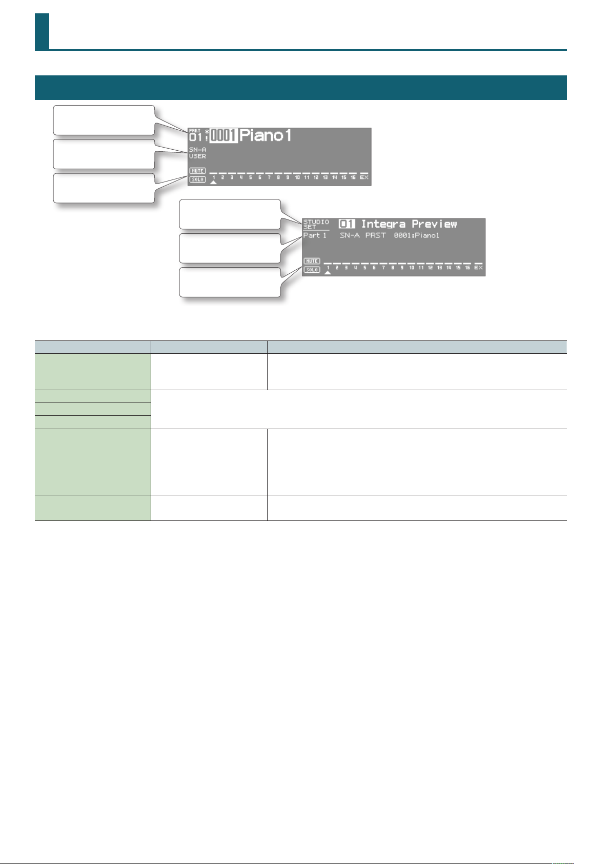
Top Screen
Part number,
Tone number/name
Tone type/bank
Solo and mute on/o for
each part
* There are two types of top screen: TYPE 1 and TYPE 2. Use [SHIFT] + [ENTER] to switch between them.
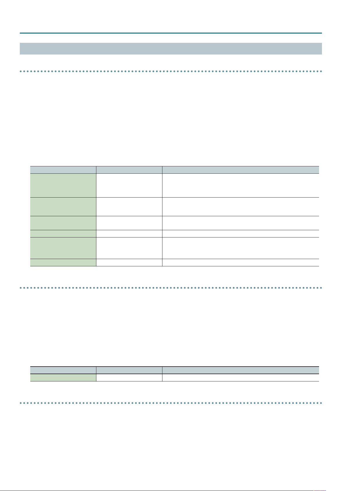
Parameter Value Explanation
Studio Set Number 1–64
Tone Type
For details, refer to “TONE tab” (p. 6) of the PART VIEW screen.Tone Bank
Tone Number
MUTE OFF, ON
SOLO OFF, 1–16
TYPE1
Studio set number/name
Part number,
Tone type/bank/name
Solo and mute on/o for
each part
TYPE2
Selects the number of the studio set.
The studio set will be switched when you change the number and press [ENTER].
(This is shown if the system setting “Top Screen” is TYPE 2.)
Mutes (ON) or un-mutes (OFF) each part.
Use this setting when, for example, you want to use the instrument for karaoke by muting the part
playing the melody, or when you want to play something using a separate sound module.
* The bar (—) above the part number is erased for parts whose mute setting is on.
* The Mute Switch parameter does not turn the part o, but sets the volume to minimum so that
no sound is heard. Therefore, MIDI messages are still received.
Only the sound of the part set to Solo will be heard.
* You can’t set the Ext part to Solo.
4
Page 5
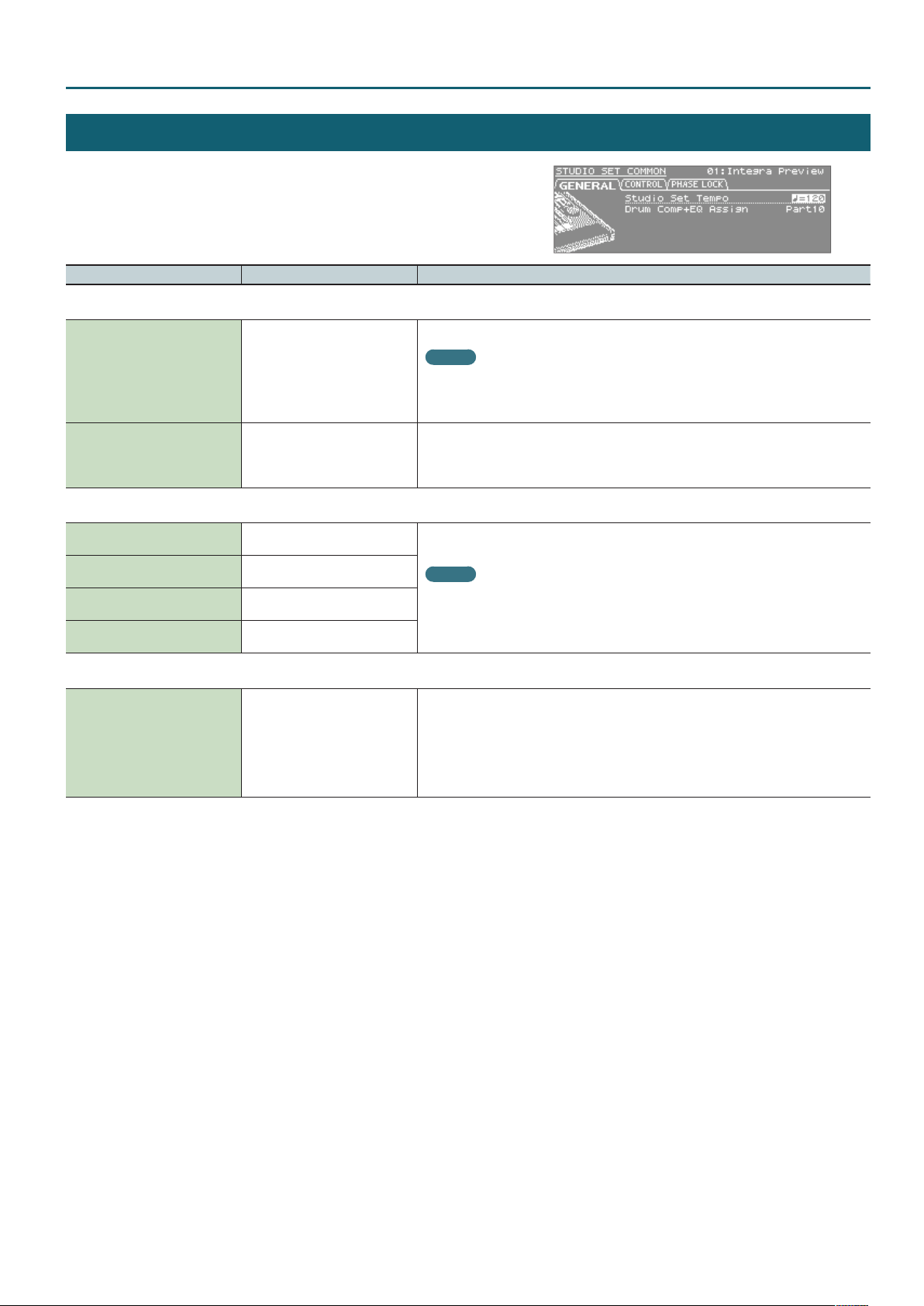
STUDIO SET COMMON
1. In the top screen, press the [MENU] button.
2. Choose “STUDIO SET COMMON,” and press the [ENTER] button.
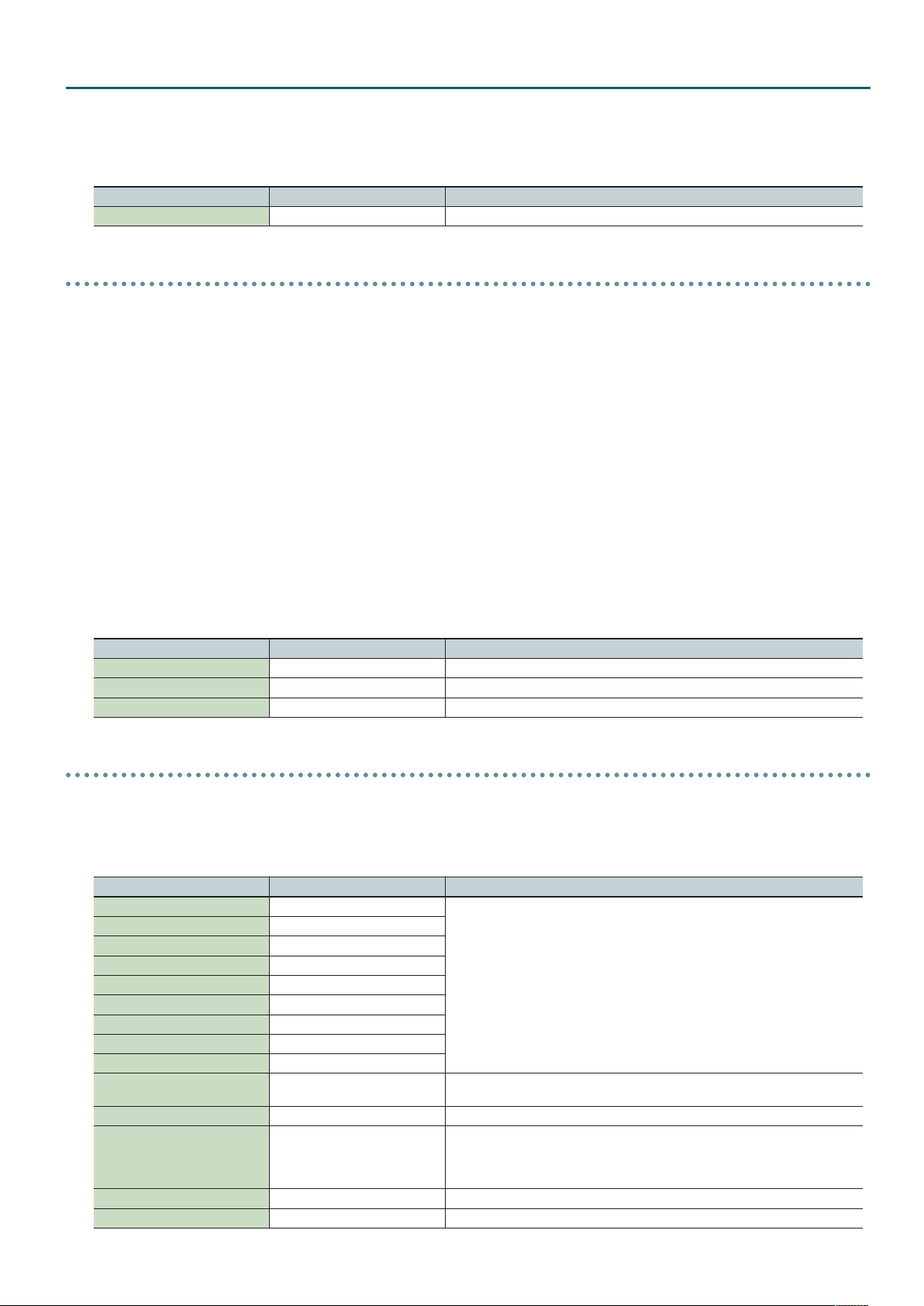
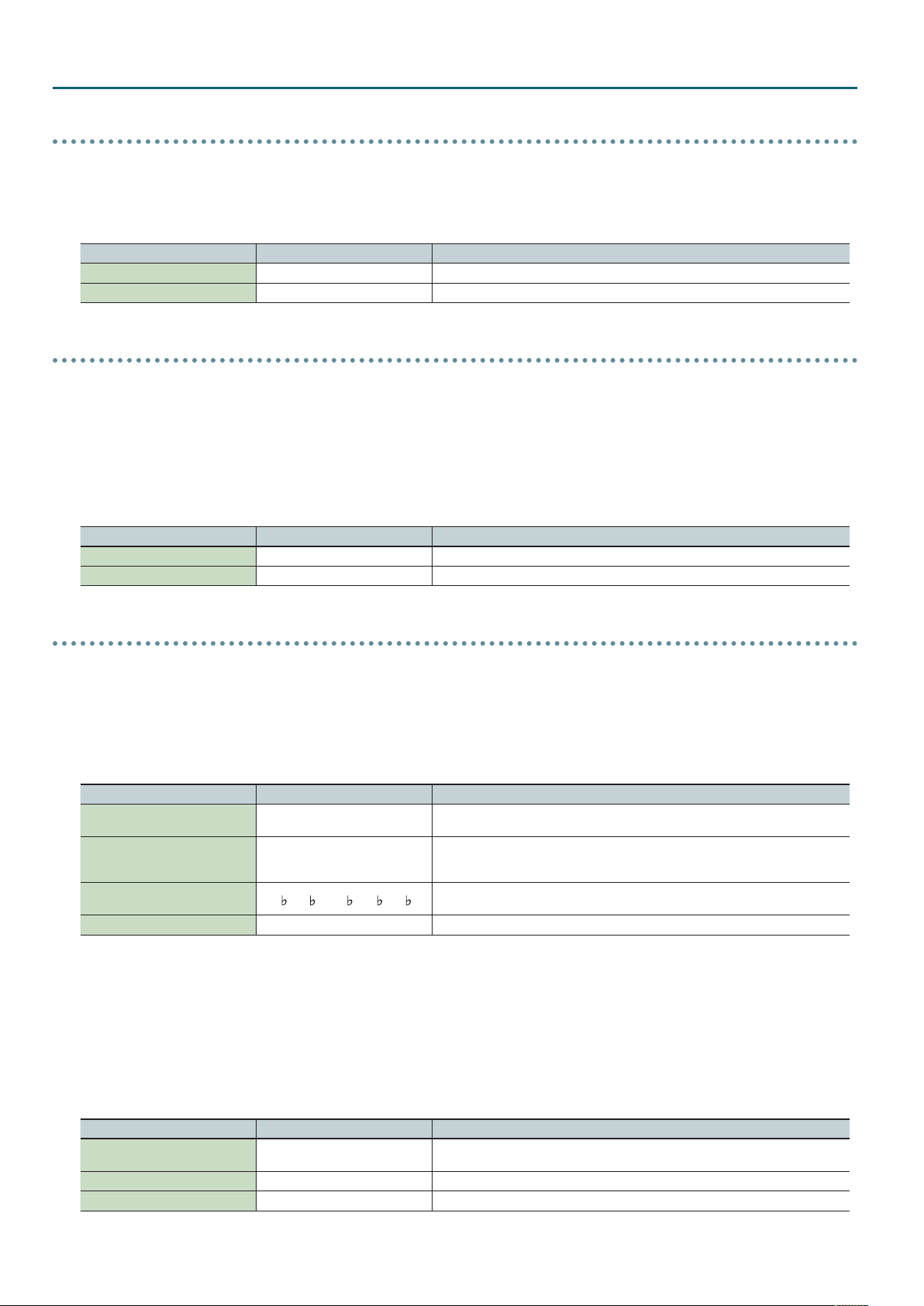
Parameter Value Explanation
GENERAL tab
Tempo for the studio set
MEMO
Studio Set Tempo 20–250
Drum Comp+EQ Assign Part1–Part16
CONTROL tab
Tone Control 1 Src
Tone Control 2 Src
Tone Control 3 Src
Tone Control 4 Src
OFF, CC01–CC31, CC33–CC95, BEND,
AFT
OFF, CC01–CC31, CC33–CC95, BEND,
AFT
OFF, CC01–CC31, CC33–CC95, BEND,
AFT
OFF, CC01–CC31, CC33–CC95, BEND,
AFT
If the system setting “Tempo Assign Source” is set to STUDIO SET, the tempo setting of the
studio set will be used as the tempo.
If “Tempo Assign Source” is set to SYSTEM, the system’s tempo setting will be used as the
tempo.
Species the part that will use the six sets of compressor + equalizer that are provided for use with
a drum kit.
* If a tone (not a drum kit) is assigned to the part specied by Drum Comp+EQ Assign, the
Comp+EQ will not be available.
Specify the MIDI messages that will be used for Tone Control of the studio set.
MEMO
If you want to use the Tone Control 1–4 Src settings of each studio set to control the tone,
set the system setting “Control Source Select” to STUDIO SET. If you want to use the system
settings System Control 1–4 Src to control the tone, set the system setting “Control Source
Select” to “SYSTEM.”
Studio Set – GENERAL tab
PHASE LOCK tab
CH 1–CH 16 OFF, ON
Set Phase Lock to “ON” when you want to suppress discrepancies in timing of parts played on the
same MIDI channel.
When the Phase Lock parameter is set to “ON,” parts on the same MIDI channel are put in
a condition in which their timing is matched, enabling them to be played at the same time.
Accordingly, a certain amount of time may elapse between reception of the Note messages and
playing of the sounds. Turn this setting to “ON” only as needed.
* Phase Lock is not available for SuperNATURAL acoustic organ-type instruments.
5
Page 6
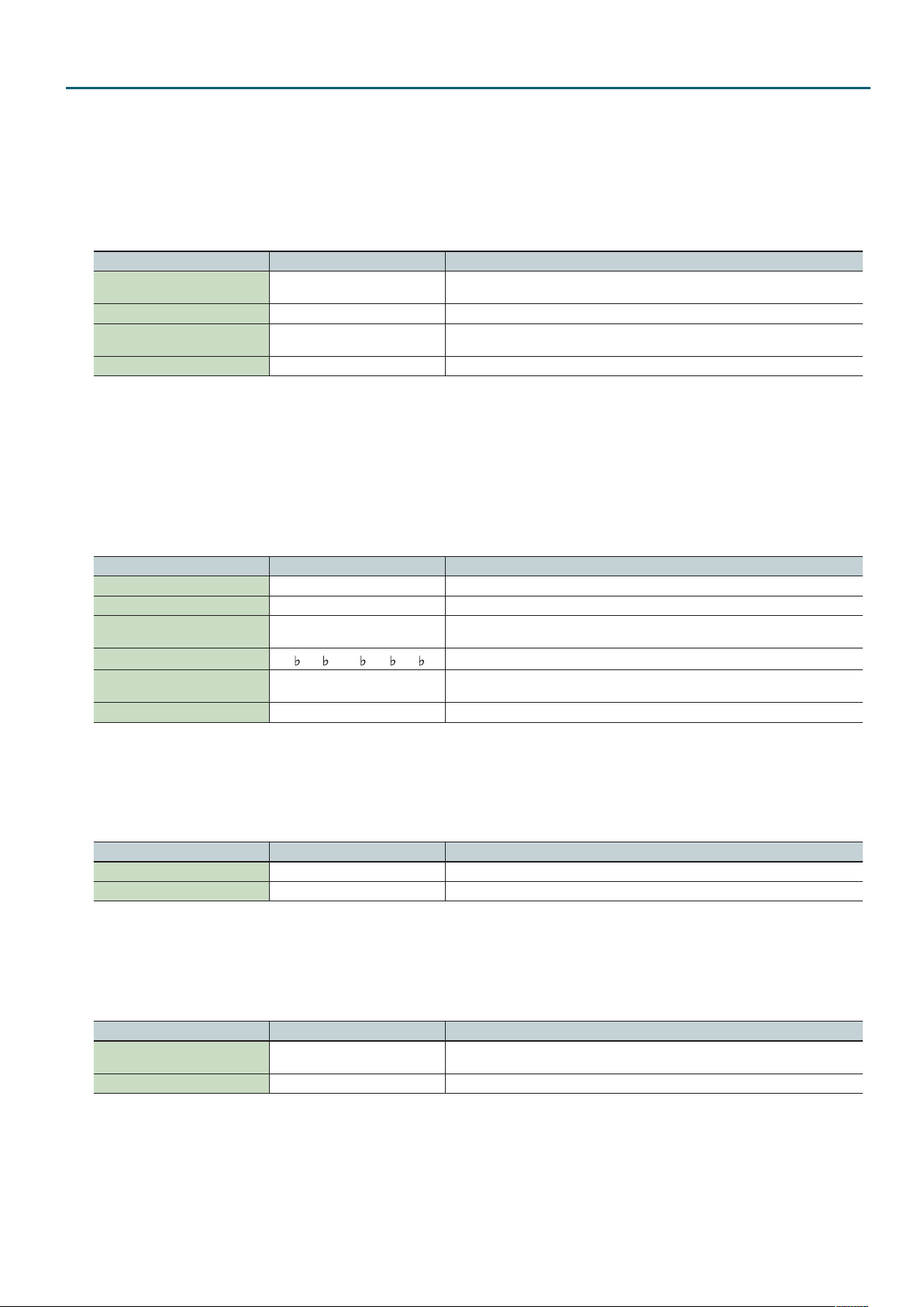
Studio Set – TONE tab
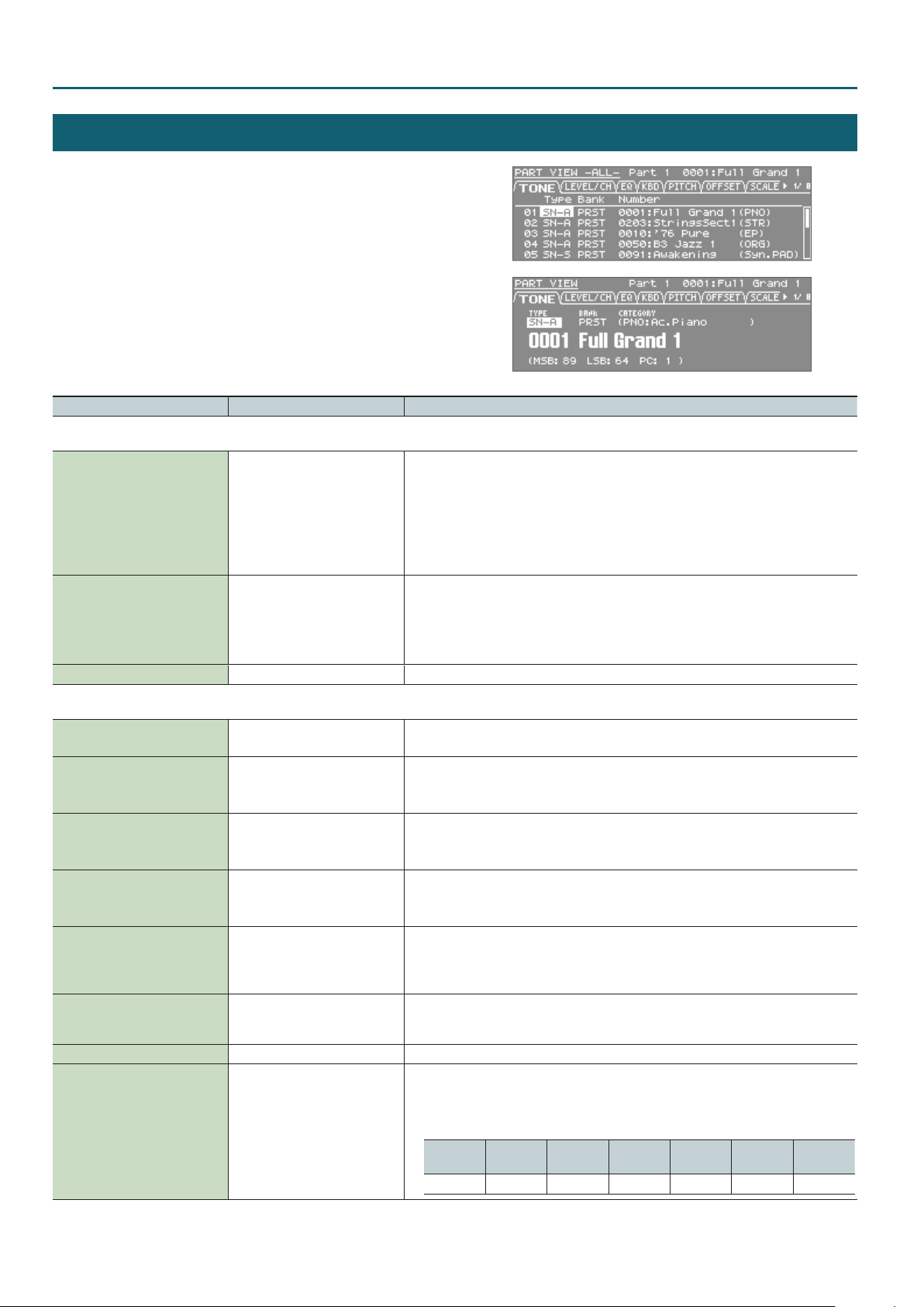
PART VIEW
1. In the top screen, press the [PART VIEW] button.
The PART VIEW -ALL- screen appears.
* Some of the part parameters are not shown in the
PART VIEW -ALL- screen.
2. Press the [PART VIEW] button again.
The PART VIEW screen appears.
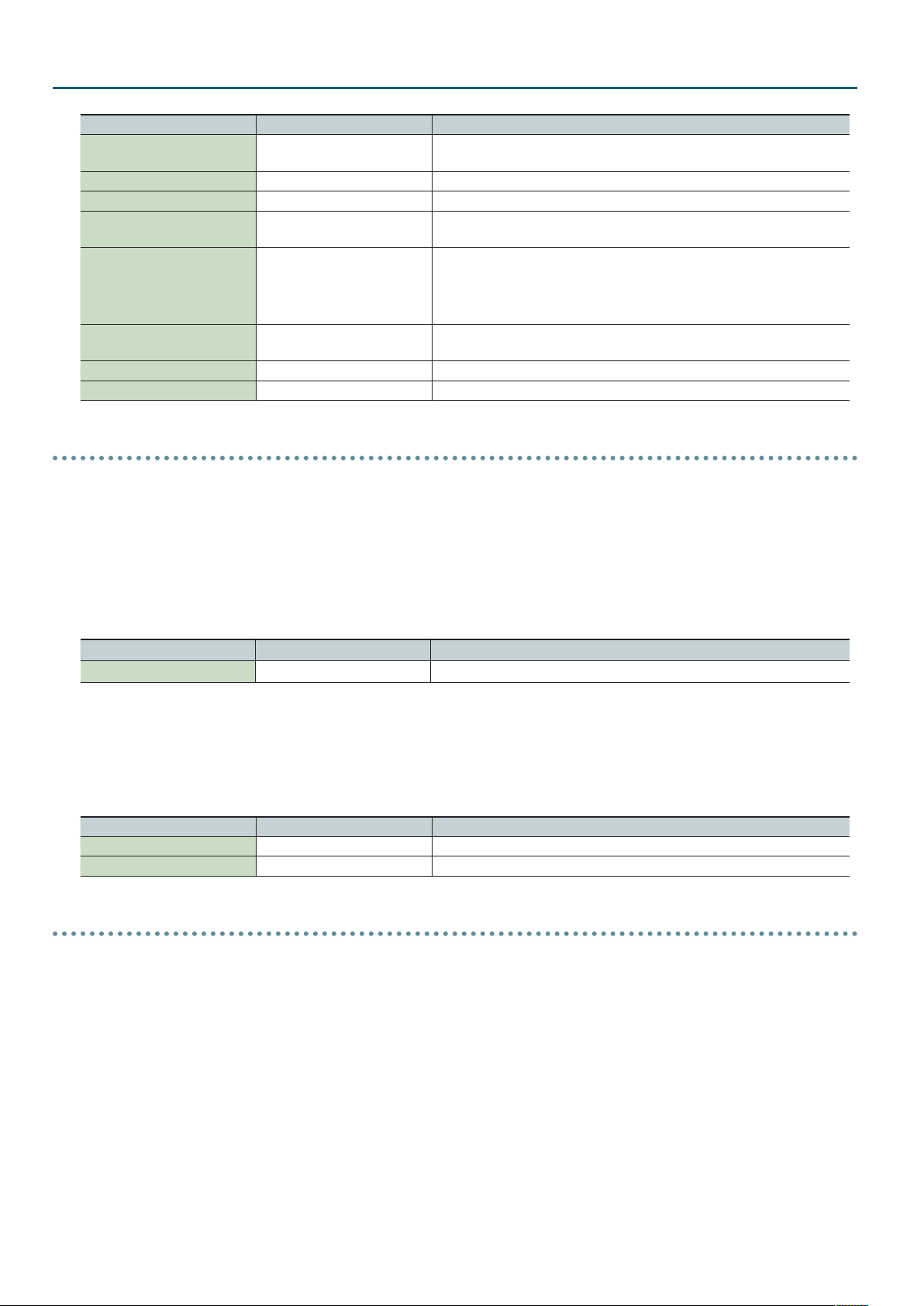
Parameter Value Explanation
TONE tab
SN-A : SuperNATURAL Acoustic Tones
SN-S : SuperNATURAL Synth Tones
SN-D : SuperNATURAL Drum Kits
PCMS : PCM Synth Tones
PCMD : PCM Drum Kits
Tone Type
SN-A, SN-S, SN-D
PCMS, PCMD
Species the type of tone/drum kit assigned to each part.
PRST, USER,
GM2 (GM2#),
Tone Bank
Tone Number 001– Selects the number of the tone/drum kit assigned to each part.
ExSN1–ExSN6,
SRX01–SRX12,
ExPCM
Selects the group of the tone/drum kit assigned to each part.
• ExSN1–5 can be selected as SN-A if that expansion is loaded
• ExSN6 can be selected as SN-D if that expansion is loaded
• SRX01–12 and ExPCM can be selected as PCMS and PCMD if that expansion is loaded
LEVEL/CH tab
Level
(Also valid for the Ext part)
Pan L64–63R
Cho Send Level
(Also valid for the Ext part)
Rev Send Level
(Also valid for the Ext part)
Output Assign A, B, C, D, 1–8
Rx Switch OFF, ON
Rx Channel 1–16 Species the MIDI receive channel for each part.
Mono/Poly MONO, POLY, TONE
0–127
0–127
0–127
Adjust the volume of each part.
This setting’s main purpose is to adjust the volume balance between parts.
Adjust the pan of each part.
“L64” is far left, “0” is center, and “63R” is far right.
* If motional surround is on, surround output will be enabled and this setting will be ignored.
Adjusts the amount of Chorus for each Part.
If you don’t want to add the Chorus eect, set it to 0.
* This has no eect if motional surround is on.
Adjusts the amount of Reverb for each Part.
If you don’t want to add the Reverb eect, set it to 0.
* This has no eect if motional surround is on.
Species for each part how the sound will be output.
A, B, C, D: The sound will be output in stereo to the OUTPUT A (MIX) jacks or from the OUTPUT B,
C, D jacks.
1–8: The sound will be output in monaural to the INDIVIDUAL 1–8 jacks.
For each part, specify whether MIDI messages will be received (ON), or not (OFF).
If this is “OFF,” the part will not respond. Normally, you should leave this “ON,” but you can turn it
“OFF” when you do not want a specic part to be playing during song playback.
Set this parameter to “MONO” when the tone assigned to the part is to be played monophonically,
or to “POLY” when the tone is to be played polyphonically. If you want to use the Mono/Poly
setting of the tone assigned to the part (p. **), set this to “TONE.”
* This is not shown in PART VIEW -ALL-.
SN-A
(Ac.Piano)
ü
SN-A
(Organ)
–
SN-A
(Other)
ü ü
SN-S SN-D PCMS PCMD
–
ü
–
6
Page 7
Parameter Value Explanation
You can add legato when performing monophonically. The term “legato” refers to a playing style
in which notes are smoothly connected to create a owing feel. This creates a smooth transition
between notes, which is eective when you wish to simulate the hammering-on and pulling-o
techniques used by a guitarist.
Turn this parameter “ON” when you want to use the Legato feature and “OFF” when you don’t. If
Legato Switch OFF, ON, TONE
you want to use the Legato Switch setting of the tone assigned to the part, set this to “TONE.”
* This is not shown in PART VIEW -ALL-.
Studio Set – EQ tab
Voice Reserve 0–63, FULL
SN-A
(Ac.Piano)
ü
This setting species the number of voices that will be reserved for each part when more than 128
voices are played simultaneously.
It is not possible for the settings of all parts to total an amount greater than 64.
* This is not shown in PART VIEW -ALL-.
SN-A
(Organ)
– –
EQ tab
EQ Switch OFF, ON EQ for each part on/o setting
EQ Low Freq 200, 400 [Hz]
EQ Low Gain -15–+15 [dB] Gain of the low frequency range
EQ Mid Freq
EQ Mid Gain -15–+15 [dB] Gain of the middle frequency range
EQ Mid Q 0.5, 1.0, 2.0, 4.0, 8.0
EQ High Freq 2000, 4000, 8000 [Hz]
EQ High Gain -15–+15 [dB] Gain of the high frequency range
200, 250, 315, 400, 500, 630, 800,
1000, 1250, 1600, 2000, 2500, 3150,
4000, 5000, 6300,8000 [Hz]
Frequency of the low range
* This is not shown in PART VIEW -ALL-.
Frequency of the middle range
* This is not shown in PART VIEW -ALL-.
Width of the middle frequency range
Set a higher value for Q to narrow the range to be aected.
* This is not shown in PART VIEW -ALL-.
Frequency of the high range
* This is not shown in PART VIEW -ALL-.
KBD tab
SN-A
(Other)
SN-S SN-D PCMS PCMD
ü
–
ü
–
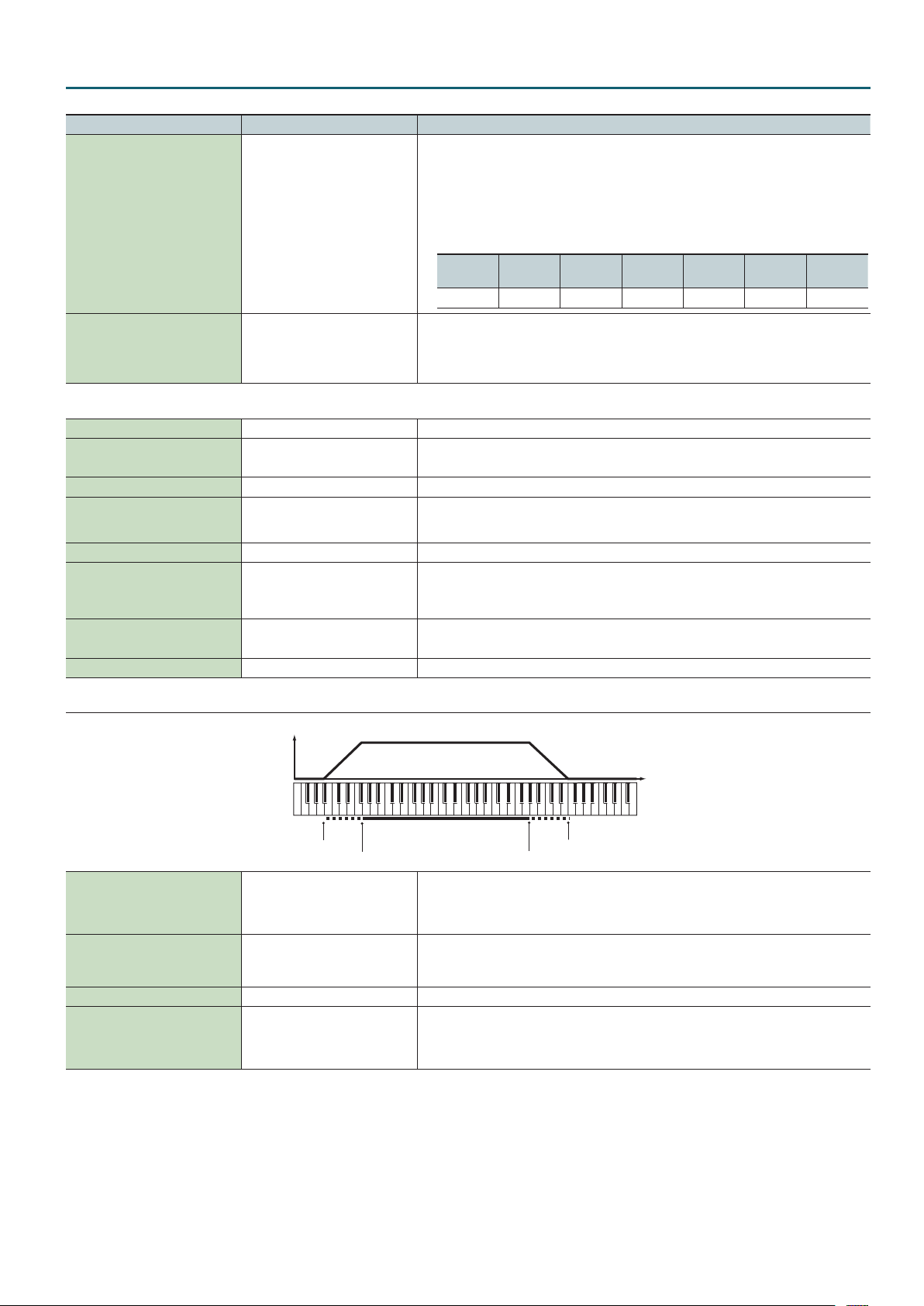
Level
Pitch
Fade Lower
Range Lower
Determines what will happen to the Part’s level when a note that’s higher than its specied
Key Fade Upper 0–127
Key Range Upper LOWER–G9
Key Range Lower C-1–UPPER Species the lowest note that the tone will sound for each part.
Key Fade Lower 0–127
keyboard range is played. Higher settings produce a more gradual change in volume.
If you don’t want the Tone to sound at all when a note above the keyboard range is played, set this
parameter to 0.
Species the highest note that the tone will sound for each part.
* It is not possible to set Lower to a value greater than the Upper value, or Upper to a value less
than the Lower value.
Determines what will happen to the Part’s level when a note that’s lower than its specied
keyboard range is played. Higher settings produce a more gradual change in volume.
If you don’t want the Tone to sound at all when a note below the keyboard range is played, set this
parameter to 0.
Range Upper
Fade Upper
7
Page 8
Studio Set – PITCH tab
Parameter Value Explanation
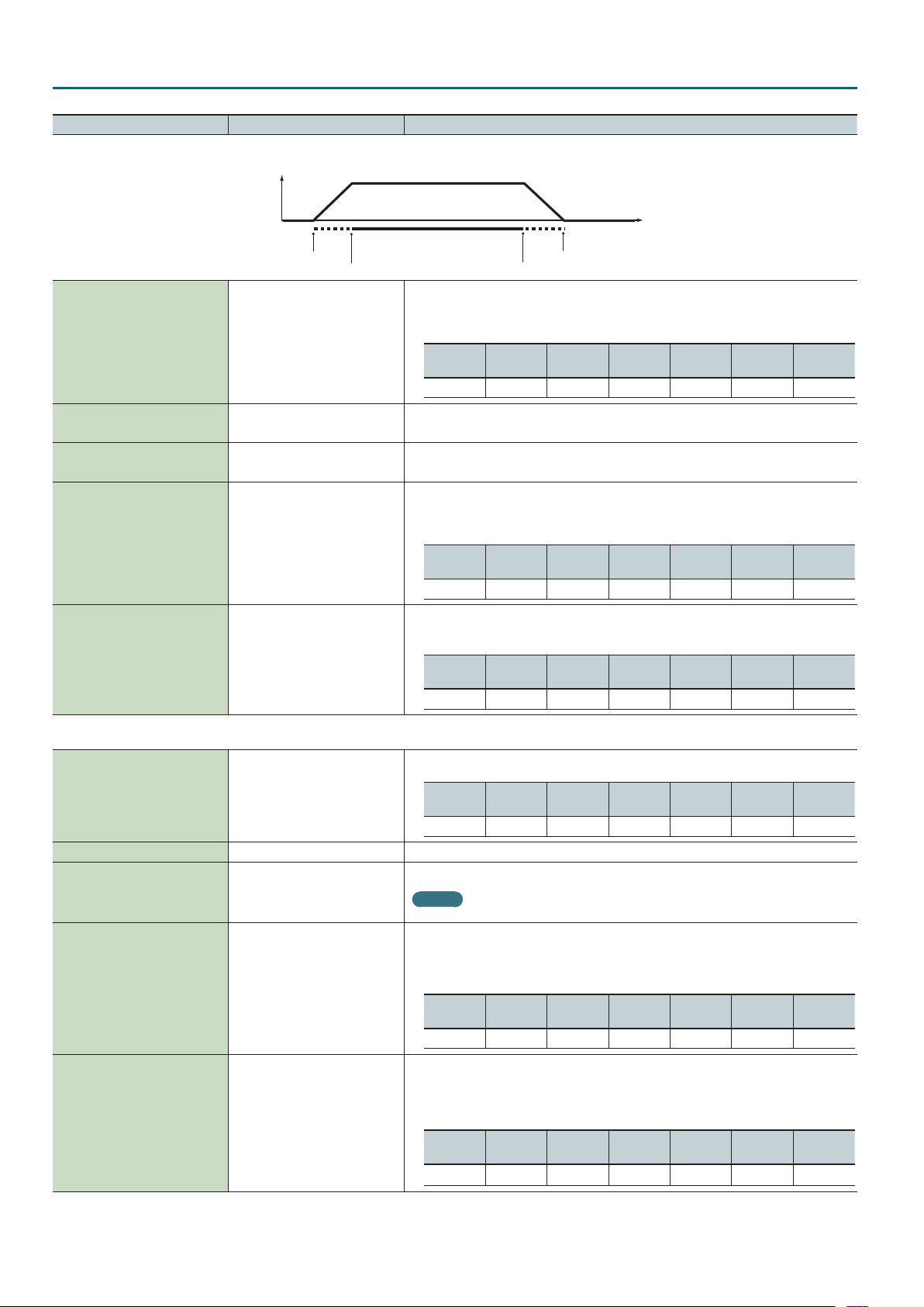
Level
Velocity
Velo Fade Upper 0–127
Velo Range Upper LOWER–127
Velo Range Lower 1–UPPER
Velo Fade Lower 0–127
Velo Sens Oset -63–+63
Fade Lower
Range Lower
Fade Upper
Range Upper
Determines what will happen to the tone’s level when the tone is played at a velocity greater than
Velo Range Upper. If you don’t want the tone to sound at all, set this parameter to “0.”
* This is not shown in PART VIEW -ALL-.
SN-A
(Ac.Piano)
ü
SN-A
(Organ)
–
SN-A
(Other)
SN-S SN-D PCMS PCMD
ü ü ü ü ü
Species the highest velocity at which the part will sound.
* This is not shown in PART VIEW -ALL-.
Species the lowest velocity at which the part will sound.
* This is not shown in PART VIEW -ALL-.
Determines what will happen to the tone’s level when the tone is played at a velocity lower than
Velo Range Lower. If you don’t want the tone to sound at all, set this parameter to “0.”
* This is not shown in PART VIEW -ALL-.
SN-A
(Ac.Piano)
ü
SN-A
(Organ)
–
SN-A
(Other)
SN-S SN-D PCMS PCMD
ü ü ü ü ü
Adjusts the velocity sensitivity. The higher the value, the greater the sensitivity.
* This is not shown in PART VIEW -ALL-.
SN-A
(Ac.Piano)
ü
SN-A
(Organ)
– –
SN-A
(Other)
SN-S SN-D PCMS PCMD
ü ü ü ü
PITCH tab
Adjusts the pitch of the part’s sound up or down in units of an octave (+/-3 octaves).
Octave Shift -3–+3
SN-A
(Ac.Piano)
ü ü ü ü
Coarse Tune -48–+48 Adjusts the pitch of the part’s sound up or down in semitone steps (+/-4 octaves).
Adjusts the pitch of the part’s sound up or down in 1-cent steps (+/- 50 cents).
Fine Tune -50–+50
MEMO
One cent is 1/100th of a semitone.
Species the amount of pitch change in semitones (2 octaves) that will occur when the Pitch Bend
Lever is moved. The amount of change when the lever is tilted is set to the same value for both left
and right sides. If you want to use the Pitch Bend Range setting of the tone assigned to the part,
set this to “TONE.”
Bend Range 0–24, TONE
SN-A
(Ac.Piano)
ü ü ü ü
Specify whether portamento will be applied. Turn this parameter “ON” when you want to apply
Portamento and “OFF” when you don’t. If you want to use the Portamento Switch setting of the
tone assigned to the part, set this to “TONE.”
* This is not shown in PART VIEW -ALL-.
Porta Switch OFF, ON, TONE
SN-A
(Ac.Piano)
ü
SN-A
(Organ)
SN-A
(Organ)
SN-A
(Organ)
–
SN-A
(Other)
SN-A
(Other)
SN-A
(Other)
ü ü
SN-S SN-D PCMS PCMD
–
SN-S SN-D PCMS PCMD
–
SN-S SN-D PCMS PCMD
–
ü
ü ü
ü
–
–
8
Page 9

Parameter Value Explanation
When portamento is used, this species the time over which the pitch will change. Higher settings
will cause the pitch change to the next note to take more time. If you want to use the Portamento
Time setting of the tone assigned to the part, set this to “TONE.”
* This is not shown in PART VIEW -ALL-.
Porta Time 0–127, TONE
SN-A
(Ac.Piano)
ü
OFFSET tab
Adjusts the cuto frequency for the tone/drum kit assigned to a part.
SN-A
(Organ)
–
SN-A
(Other)
ü ü
Studio Set – OFFSET tab
SN-S SN-D PCMS PCMD
–
ü
–
Cuto Oset -64–+63
Reso Oset -64–+63
Attack Oset -64–+63
Decay Oset -64–+63
Release Oset -64–+63
SN-A
(Ac.Piano)
– –
SN-A
(Organ)
SN-A
(Other)
ü* ü
SN-S SN-D PCMS PCMD
–
ü ü
* For some tones, the eect may be dicult to notice.
Adjusts the Resonance for the tone/drum kit assigned to a part.
SN-A
(Ac.Piano)
– –
SN-A
(Organ)
SN-A
(Other)
ü* ü
SN-S SN-D PCMS PCMD
–
ü ü
* For some tones, the eect may be dicult to notice.
Adjusts the Attack Time for the tone/drum kit assigned to a part.
SN-A
(Ac.Piano)
– –
SN-A
(Organ)
SN-A
(Other)
ü ü
SN-S SN-D PCMS PCMD
–
ü ü
Adjusts the Decay Time for the tone/drum kit assigned to a part.
SN-A
(Ac.Piano)
– – –
SN-A
(Organ)
SN-A
(Other)
SN-S SN-D PCMS PCMD
ü ü ü ü
Adjusts the Release Time for the tone/drum kit assigned to a part.
SN-A
(Ac.Piano)
– –
SN-A
(Organ)
SN-A
(Other)
SN-S SN-D PCMS PCMD
ü ü ü ü ü
For each part, adjust the vibrato speed (the rate at which the pitch is modulated). The pitch will be
modulated more rapidly for higher settings, and more slowly with lower settings.
* This is not shown in PART VIEW -ALL-.
Vibrato Rate -64–+63
Vibrato Depth -64–+63
Vibrato Delay -64–+63
SN-A
(Ac.Piano)
ü
SN-A
(Organ)
–
SN-A
(Other)
ü* ü
SN-S SN-D PCMS PCMD
–
ü ü
* This eect does not apply to instruments of the Bell/Mallet and Percussion categories.
For each part, this adjusts the depth of the vibrato eect (the depth at which the pitch is modulated).
The pitch will be modulated more greatly for higher settings, and less with lower settings.
* This is not shown in PART VIEW -ALL-.
SN-A
(Ac.Piano)
ü
SN-A
(Organ)
–
SN-A
(Other)
ü* ü
SN-S SN-D PCMS PCMD
–
ü ü
* This eect does not apply to instruments of the Bell/Mallet and Percussion categories.
For each part, this adjusts the time delay until the vibrato (pitch modulation) eect begins. Higher settings
will produce a longer delay time before vibrato begins, while lower settings produce a shorter time.
* This is not shown in PART VIEW -ALL-.
SN-A
(Ac.Piano)
ü
SN-A
(Organ)
–
SN-A
(Other)
ü* ü
SN-S SN-D PCMS PCMD
–
ü ü
* This eect does not apply to instruments of the Bell/Mallet and Percussion categories.
9
Page 10
Studio Set – SCALE tab
Parameter Value Explanation
SCALE tab
These are templates that set all of the Scale Tune C–B settings.
CUSTOM: Specify the tuning individually for Scale Tune C–B.
EQUAL: Equal temperament
JUST-MAJ: Just intonation (major)
Scale Tune Type
CUSTOM,
EQUAL,
JUST-MAJ,
JUST-MIN,
PYTHAGORE,
KIRNBERGE,
MEANTONE,
WERCKMEIS,
ARABIC
JUST-MIN: Just intonation (minor)
PYTHAGORE: Pythagorean tuning
KIRNBERGE: Kirnberger (type 3)
MEANTONE: Meantone temperament
WERCKMEIS: Werckmeister (type 1, number 3)
ARABIC: Arabic scale
Scale Tune Key C, C#, D, D#, E, F, F#, G, G#, A, A#, B
Scale Tune for C–B -64–+63
MIDI tab
PC
(Rx Program Change)
BS
(Rx Bank Select)
PB
(Rx Pitch Bend)
PA
(Rx Poly Key Press)
CA
(Rx Ch Press)
MD
(Rx Modulation)
VO
(Rx Volume)
PN
(Rx Pan)
EX
(Rx Expression)
HD
(Rx Hold-1)
OFF, ON
OFF, ON
OFF, ON
OFF, ON
OFF, ON
OFF, ON
OFF, ON
OFF, ON For each MIDI channel, specify whether MIDI Pan messages will be received “ON”, or not “OFF”.
OFF, ON
OFF, ON For each MIDI channel, specify whether MIDI Hold 1 messages will be received “ON”, or not “OFF”.
SN-A
(Ac.Piano)
ü
Species the tonic note for the scale tune template.
SN-A
(Ac.Piano)
ü
Species the scale tuning.
* This is not shown in PART VIEW -ALL-.
SN-A
(Ac.Piano)
ü
For each MIDI channel, specify whether MIDI Program Change messages will be received “ON”, or
not “OFF”.
For each MIDI channel, specify whether MIDI Bank Select messages will be received “ON”, or not
“OFF”.
For each MIDI channel, specify whether MIDI Pitch Bend messages will be received “ON”, or not
“OFF”.
For each MIDI channel, specify whether MIDI polyphonic key pressure messages will be received
“ON”, or not “OFF”.
For each MIDI channel, specify whether MIDI Channel Pressure messages will be received “ON”, or
not “OFF”.
For each MIDI channel, specify whether MIDI Modulation messages will be received “ON”, or not
“OFF”.
For each MIDI channel, specify whether MIDI Volume messages will be received “ON”, or not
“OFF”.
For each MIDI channel, specify whether MIDI Expression messages will be received “ON”, or not
“OFF”.
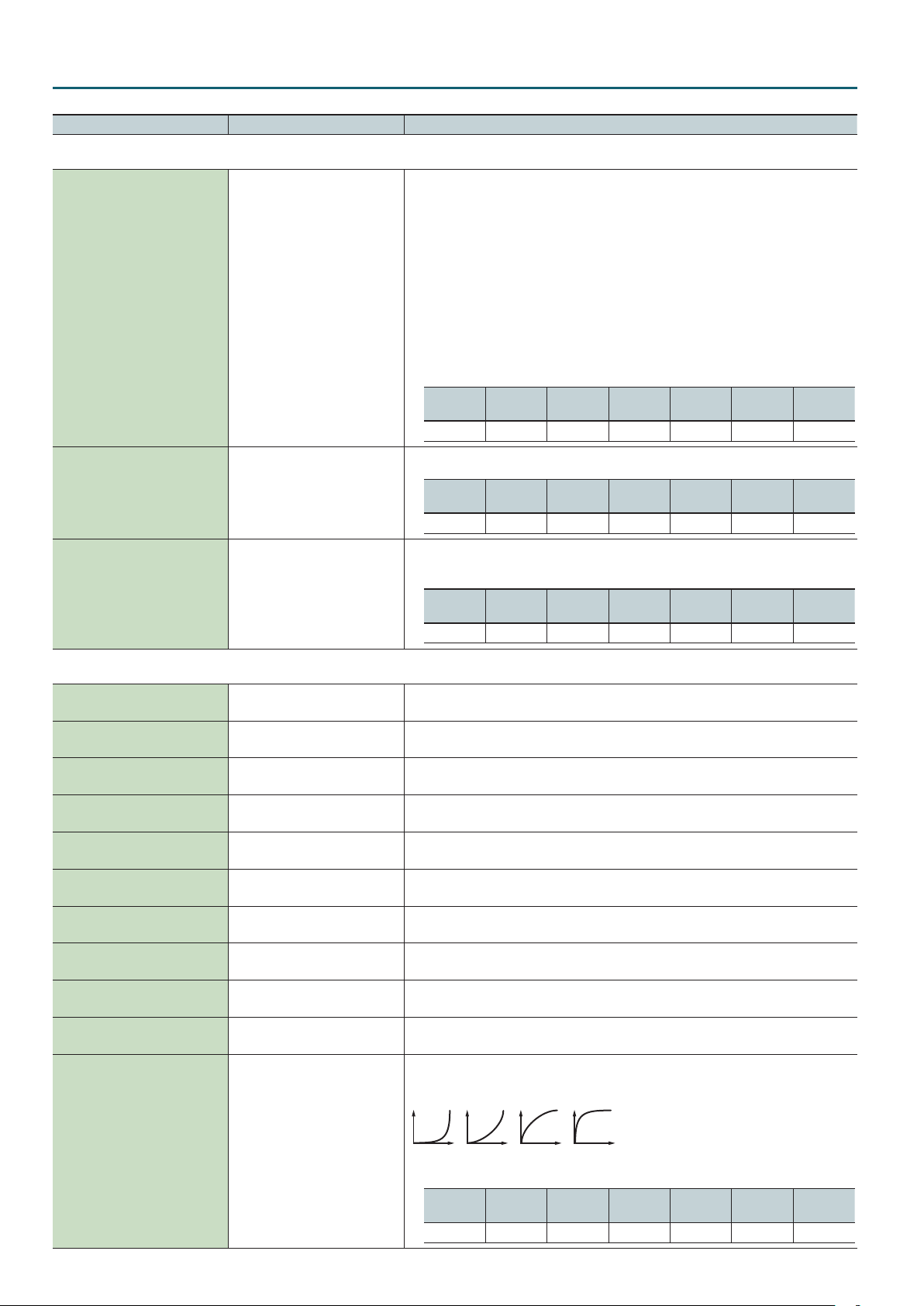
Velocity Curve selects for each part one of the four following Velocity Curve types that best
matches the touch of the connected MIDI keyboard. Set this to “OFF” if you are using the MIDI
keyboard’s own velocity curve.
SN-A
(Organ)
–
SN-A
(Organ)
–
SN-A
(Organ)
–
SN-A
(Other)
ü ü
SN-A
(Other)
ü ü
SN-A
(Other)
ü ü
SN-S SN-D PCMS PCMD
–
SN-S SN-D PCMS PCMD
–
SN-S SN-D PCMS PCMD
–
ü ü
ü ü
ü ü
VC
(Velo Crv Type)
10
OFF, 1–4
SN-A
(Ac.Piano)
ü
21 3 4
SN-A
(Organ)
–
SN-A
(Other)
ü ü ü ü ü
SN-S SN-D PCMS PCMD
Page 11
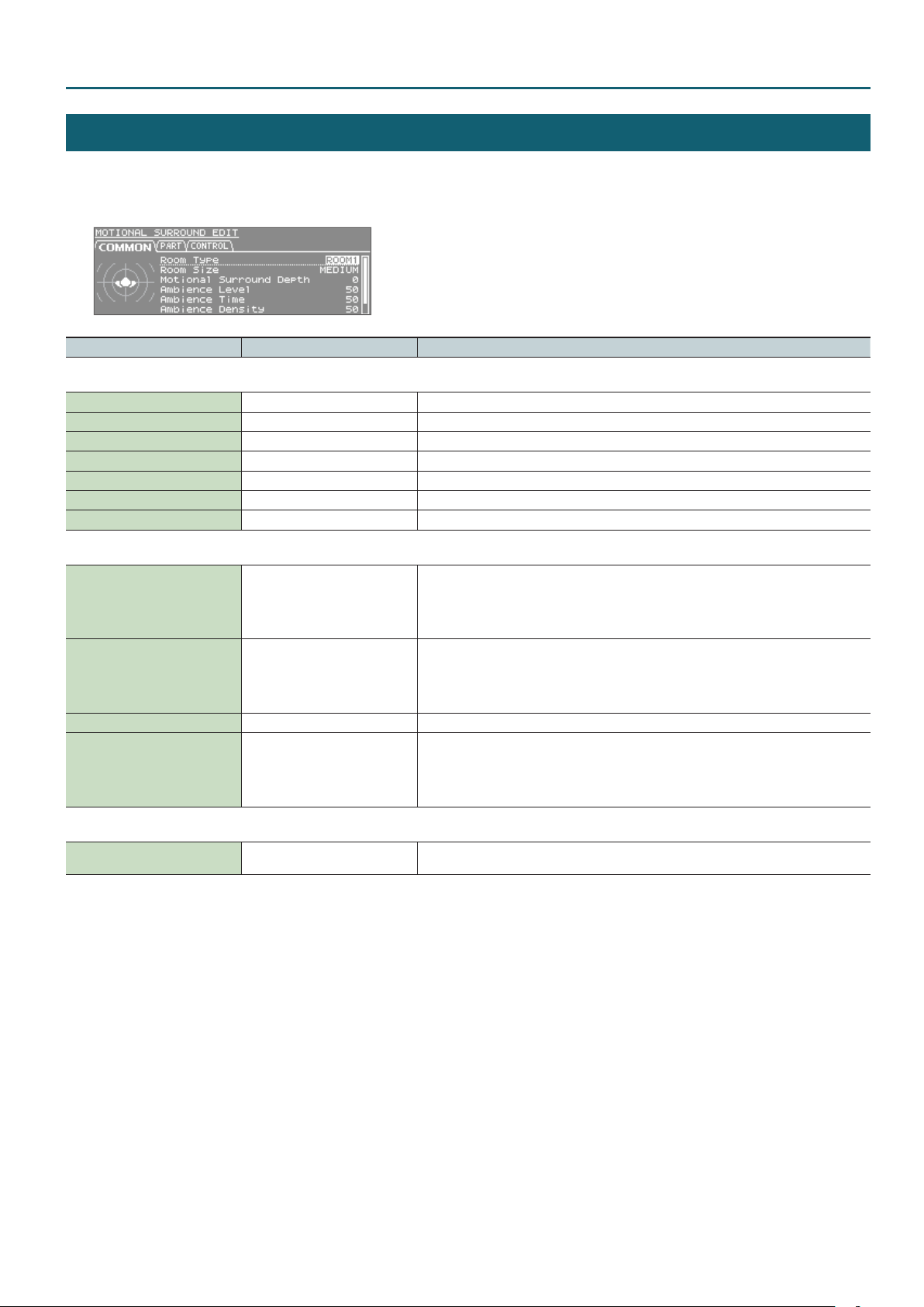
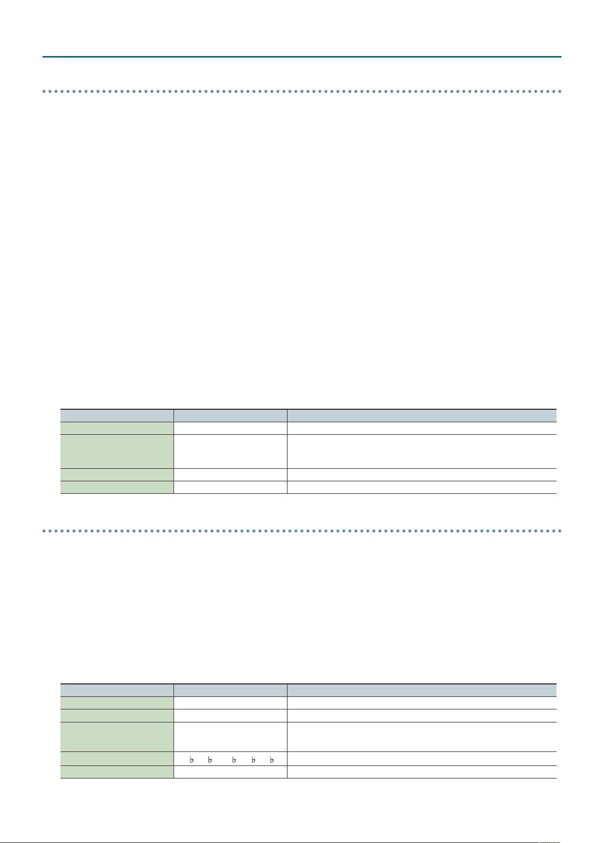
Studio Set – COMMON tab
MOTIONAL SURROUND
1. Press the [MOTIONAL SURROUND] button.
2. Press the [ENTER] button.
Parameter Value Explanation
COMMON tab
Room Type ROOM1, ROOM2, HALL1, HALL2 Species the room type.
Room Size SMALL, MEDIUM, LARGE Species the room size.
Motional Surround Depth 0–100 Species the depth of the Motional Surround eect.
Ambience Level 0–127 Species the volume of ambience.
Ambience Time 0–100 Species the duration of ambience.
Ambience Density 0–100 Species the density of ambience.
Ambience HF Damp 0–100 Species the frequency at which the high range of the ambience will be cut.
PART tab
Species the left/right position.
Part L-R -64–+63
Part F-B -64–+63
Part Width 0–32 Species the width of the positioned sound.
Part Ambience Send Level 0–127
Control change number
• 1–16 Part : CC12
• Ext Part : CC28
Species the front/rear (back) position.
Control change number
• 1–16 Part : CC13
• Ext Part : CC29
Species the send level to ambience
Control change number
• 1–16 Part : CC14
• Ext Part : CC30
CONTROL tab
Ext Part Control Ch 1–16, OFF
Species the MIDI channel used when controlling the front/back/left/right position and ambience
send level of an Ext part via MIDI.
11
Page 12
Studio Set – CONTROL tab
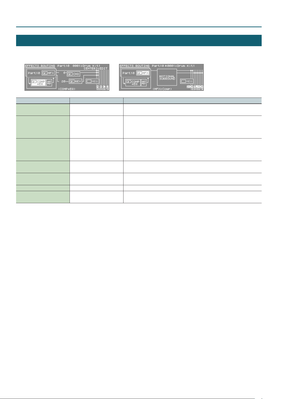
EFFECTS ROUTING
1. In the top screen, press the [EFFECTS] button.
Motional surround : ONMotional surround : OFF
Parameter Value Explanation
MFX Switch OFF, ON
Cho Send Level
(Also valid for the Ext part)
Rev Send Level
(Also valid for the Ext part)
Chorus Switch OFF, ON
Reverb Switch OFF, ON
Master EQ Switch OFF, ON Switches the Master EQ on/o.
Comp+EQ Switch OFF, ON
OFF, ON
OFF, ON
Species whether Multi-Eect will be used (ON) or not used (OFF).
* You can also set this in the tone MFX tab for each type.
Adjusts the amount of Chorus for each Part.
If you don’t want to add the Chorus eect, set it to 0.
* You can also set this in the LEVEL/CH tab of PART VIEW (p. 6).
* This is ignored if motional surround is on.
Adjusts the amount of Reverb for each Part.
If you don’t want to add the Reverb eect, set it to 0.
* You can also set this in the LEVEL/CH tab of PART VIEW (p. 6).
* This is ignored if motional surround is on.
Species whether chorus will be used (ON) or not used (OFF).
* This is ignored if motional surround is on.
Species whether Reverb will be used (ON) or not used (OFF).
* This is ignored if motional surround is on.
Turns the six drum kit compressor + equalizer units on/o together.
* This is shown only if you’ve selected the part specied by Drum Comp+EQ Assign.
12
Page 13
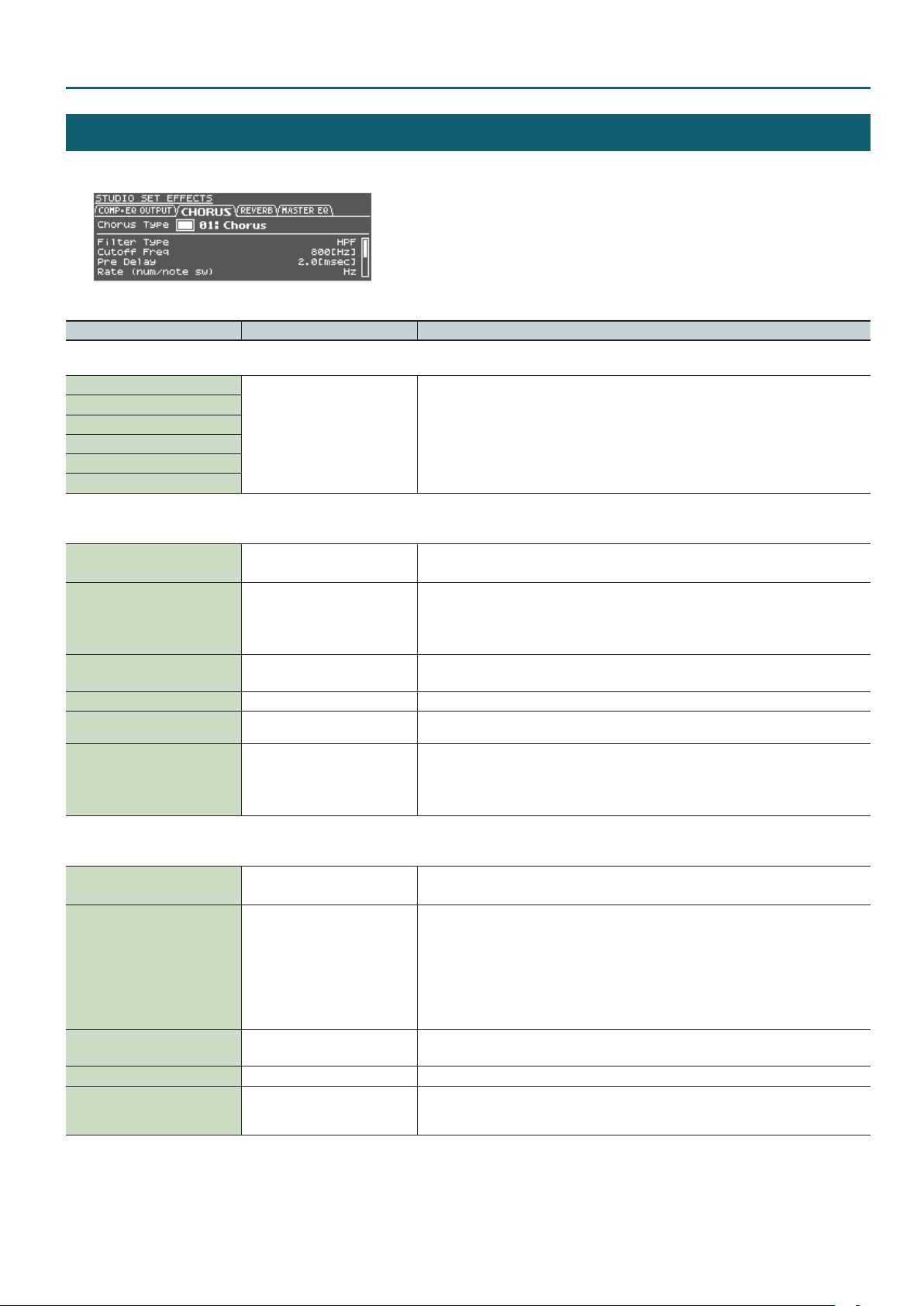
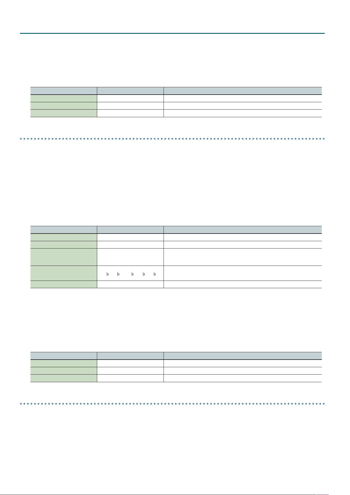
Studio Set – COMP+EQ OUTPUT tab
STUDIO SET EFFECTS
1. In the EFFECTS ROUTING screen, move the cursor to the eect that you want to edit, and press the [ENTER] button.
* MFX and COMP+EQ can be set individually for each tone.
Parameter Value Explanation
COMP+EQ OUTPUT tab
Comp+EQ 1 Output Assign
Comp+EQ 2 Output Assign
Comp+EQ 3 Output Assign
Comp+EQ 4 Output Assign
Comp+EQ 5 Output Assign
Comp+EQ 6 Output Assign
PART, A, B, C, D, 1–8
CHORUS tab
* This is ignored if motional surround is on.
Chorus Switch OFF, ON
00: OFF
Chorus Type
Chorus Parameter -
Chorus Level 0–127 Adjusts the volume of the sound that has passed through chorus.
Chorus Output Assign A, B, C, D
Chorus Output Select MAIN, REV, MAIN+REV
01: Chorus
02: Delay
03: GM2 Chorus
Specify the output destination for each the six drum kit compressor + equalizer units.
PART: Input to the MFX of the part.
A, B, C, D: Output in stereo to the OUTPUT A (MIX) jacks or the OUTPUT B, C, D jacks.
1–8: Output in monaural to the INDIVIDUAL 1–8 jacks.
* If motional surround is on, the output from each compressor + equalizer will always be the MFX
of the part, regardless of the COMP+EQ Output Assign setting.
Switches the chorus on/o.
* This is ignored if motional surround is on.
Selects the types of chorus.
Choose “00: OFF” if you don’t want to apply a chorus.
Edit the parameters for the selected chorus type.
Refer to “Chorus Parameters” (p. 98).
Selects the pair of OUTPUT jacks to which the chorus sound is routed when Chorus Output Select
is set to “MAIN” or “MAIN+REV.”
Species how the sound routed through chorus will be output.
MAIN: Output in stereo to the OUTPUT jacks.
REV: Output in monaural to the reverb.
MAIN+REV: Output in stereo to the OUTPUT jacks, and in monaural to the reverb.
REVERB tab
* This is ignored if motional surround is on.
Reverb Switch OFF, ON
00: OFF
01: Room 1
02: Room 2
Reverb Type
Reverb Parameter -
Reverb Level 0–127 Adjusts the volume of the sound that has passed through reverb.
Reverb Output Assign A, B, C, D
03: Hall 1
04: Hall 2
05: Plate
06: GM2 Reverb
Switches the reverb on/o.
* This is ignored if motional surround is on.
Selects the types of reverb.
Choose “00: OFF” if you don’t want to apply a reverb.
Edit the parameters for the selected reverb type.
Refer to “Reverb Parameters” (p. 98).
Species how the sound routed through reverb will be output.
A, B, C, D: Output in stereo to the OUTPUT A (MIX) jacks or the OUTPUT B, C, D jacks.
13
Page 14

Studio Set – MASTER EQ tab
Parameter Value Explanation
MASTER EQ tab
Master EQ Switch OFF, ON Master EQ on/o setting
EQ Low Freq 200, 400 [Hz] Frequency of the low range
EQ Low Gain -15–+15 [dB] Gain of the low frequency range
EQ Mid Freq
EQ Mid Gain -15–+15 [dB] Gain of the middle frequency range
EQ Mid Q 0.5, 1.0, 2.0, 4.0, 8.0
EQ High Freq 2000, 4000, 8000 [Hz] Frequency of the high range
EQ High Gain -15–+15 [dB] Gain of the high frequency range
200, 250, 315, 400, 500, 630, 800,
1000, 1250, 1600, 2000, 2500, 3150,
4000, 5000, 6300,8000 [Hz]
Frequency of the middle range
Width of the middle frequency range
Set a higher value for Q to narrow the range to be aected.
14
Page 15
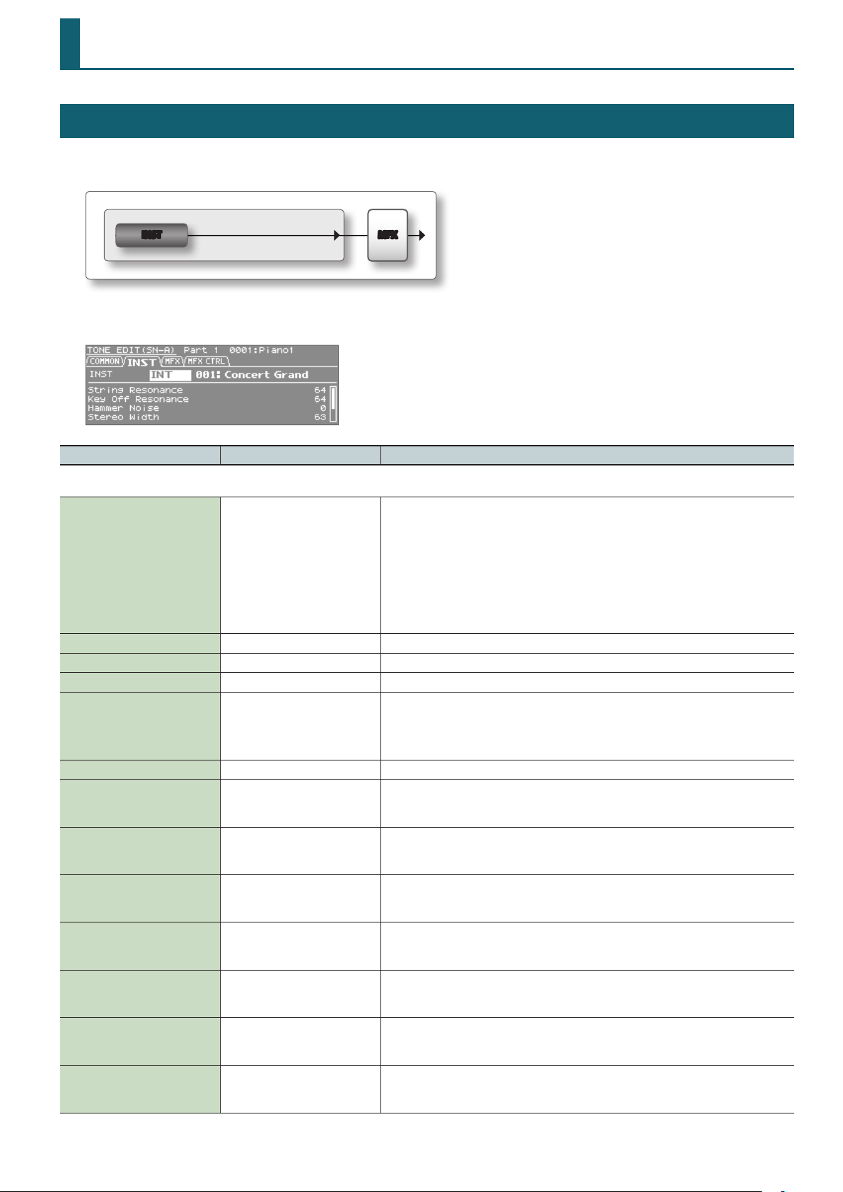
SuperNATURAL Acoustic Tone (SN-A)
TONE EDIT (SN-A)
For each tone, there are instrument settings (INST) and multi-eect settings (MFX).
The instrument settings let you make settings for the tone and its parameters.
MFXINST
1. In the top screen, press the [EDIT] button.
Parameter Value Explanation
COMMON tab
No assign, Ac.Piano, E.Piano, Organ,
Other Keyboards, Accordion/
Harmonica, Bell/Mallet, Ac.Guitar,
E.Guitar, Dist.Guitar, Ac.Bass, E.Bass,
Category
Phrase Number 0–87 Number of the phrase that plays when you press the [VOLUME] knob (PREVIEW).
Phrase Octave Shift -3–+3 Pitch (in one-octave units) of the preview phrase.
Tone Level 0–127 Adjusts the volume of the tone.
Mono/Poly MONO, POLY
Octave Shift -3–+3 Adjusts the pitch of the patch’s sound up or down in units of an octave (+/-3 octaves).
Cuto Oset -64–+63
Resonance Oset -64–+63
Attack Time Oset -64–+63
Release Time Oset -64–+63
Portamento Time Oset -64–+63
Vibrato Rate -64–+63
Vibrato Depth -64–+63
Synth Bass, Plucked/Stroke, Strings,
Brass, Wind, Flute, Sax, Recorder, Vox/
Choir, Synth Lead, Synth Brass, Synth
Pad/Strings, Synth Bellpad, Synth
PolyKey, FX, Synth Seq/Pop, Phrase,
Pulsating, Beat&Groove, Hit, Sound
FX, Drums, Percussion, Combination
Selects the category of the tone.
Species whether the patch will play polyphonically (POLY) or monophonically (MONO).
MONO: Only the last-played note will sound.
POLY: Two or more notes can be played simultaneously.
* This parameter will not appear when INT 029: TW Organ is selected.
Adjusts the cuto frequency Oset for the instrument assigned to a tone.
* This parameter will not appear when any of INT 001: Concert Grand, INT 009: Honky-tonk, or INT
029: TW Organ is selected.
Adjusts the Resonance Oset for the instrument assigned to a tone.
* This parameter will not appear when any of INT 001: Concert Grand, INT 009: Honky-tonk, or INT
029: TW Organ is selected.
Adjusts the TVA Envelope Attack Time Oset for the instrument assigned to a tone.
* This parameter will not appear when any of INT 001: Concert Grand, INT 009: Honky-tonk, or INT
029: TW Organ is selected.
Adjusts the TVA Envelope Release Time Oset for the instrument assigned to a tone.
* This parameter will not appear when any of INT 001: Concert Grand, INT 009: Honky-tonk, or INT
029: TW Organ is selected.
When portamento is used, this species the time over which the pitch will change. Higher settings
will cause the pitch change to the next note to take more time.
* This parameter will not appear when INT 029: TW Organ is selected.
Adjust the vibrato speed (the rate at which the pitch is modulated). The pitch will be modulated
more rapidly for higher settings, and more slowly with lower settings.
* This eect does not apply to instruments of the Organ, Bell/Mallet, or Percussion categories.
This adjusts the depth of the vibrato eect (the depth at which the pitch is modulated). The pitch
will be modulated more greatly for higher settings, and less with lower settings.
* This eect does not apply to instruments of the Organ, Bell/Mallet, or Percussion categories.
15
Page 16
SuperNATURAL Acoustic Tone (SN-A) – INST tab
Parameter Value Explanation
This adjusts the time delay until the vibrato (pitch modulation) eect begins. Higher settings will
Vibrato Delay -64–+63
produce a longer delay time before vibrato begins, while lower settings produce a shorter time.
* This eect does not apply to instruments of the Organ, Bell/Mallet, or Percussion categories.
INST tab
INST BANK
INST NUMBER 001– Select the instrument number of the tone.
Parameters for the each inst
INT,
ExSN1–ExSN5
(only if an expansion is loaded)
Make parameter settings for the selected instrument.
Refer to “SuperNATURAL INST Parameters” (p. 18).
Select the instrument bank of the tone.
INT: Internal sound bank
ExSN1–ExSN5: Expanded sound bank
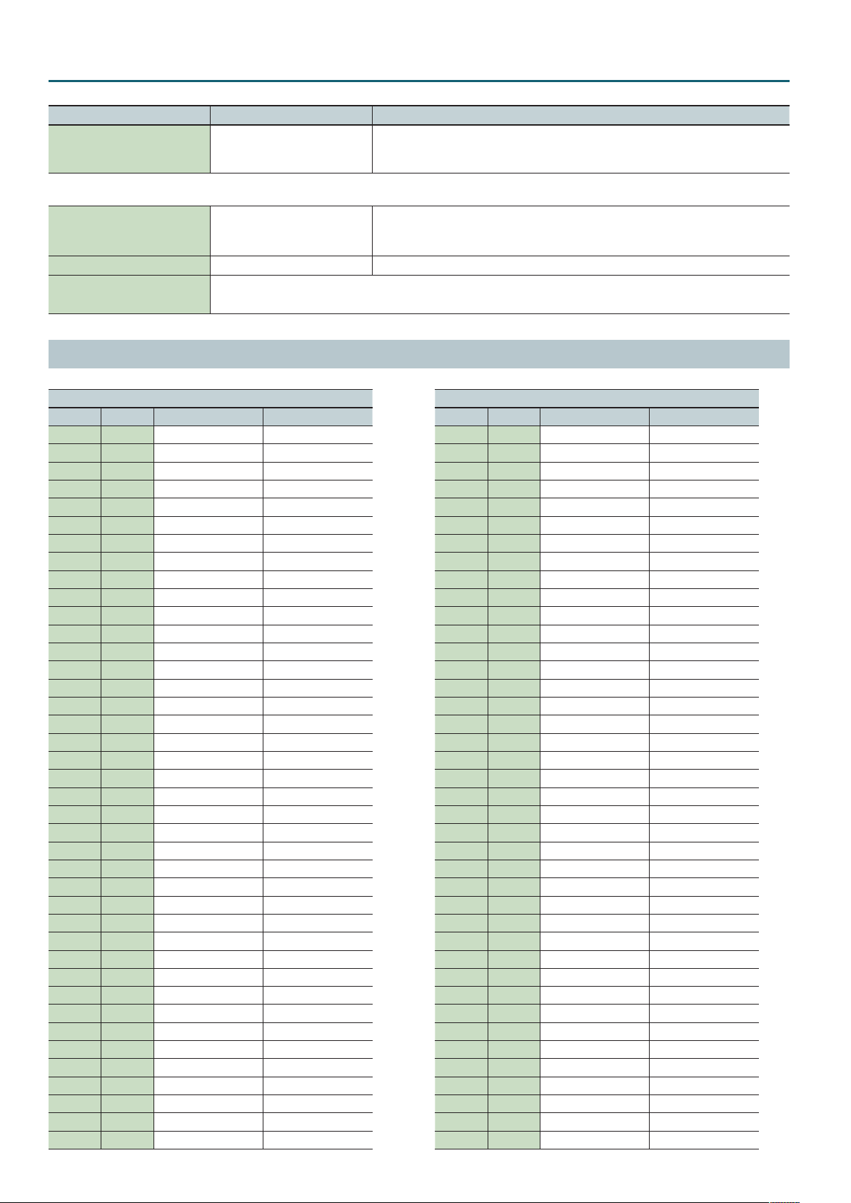
Instrument List
INST
BANK NUM NAME Category
INT 1 ConcertGrand Ac.Piano
INT 2 Grand Piano1 Ac.Piano
INT 3 Grand Piano2 Ac.Piano
INT 4 Grand Piano3 Ac.Piano
INT 5 Mellow Piano Ac.Piano
INT 6 Bright Piano Ac.Piano
INT 7 UprightPiano Ac.Piano
INT 8 Concert Mono Ac.Piano
INT 9 Honky-tonk Ac.Piano
INT 10 Pure Vintage EP1 E.Piano
INT 11 Pure Vintage EP2 E.Piano
INT 12 Pure Wurly E.Piano
INT 13 Pure Vintage EP3 E.Piano
INT 14 Old Hammer EP E.Piano
INT 15 Dyno Piano E.Piano
INT 16 Clav CB Flat Other Keyboards
INT 17 Clav CA Flat Other Keyboards
INT 18 Clav CB Medium Other Keyboards
INT 19 Clav CA Medium Other Keyboards
INT 20 Clav CB Brillia Other Keyboards
INT 21 Clav CA Brillia Other Keyboards
INT 22 Clav CB Combo Other Keyboards
INT 23 Clav CA Combo Other Keyboards
INT 24 Glockenspiel Bell/Mallet
INT 25 Vibraphone Bell/Mallet
INT 26 Marimba Bell/Mallet
INT 27 Xylophone Bell/Mallet
INT 28 Tubular Bells Bell/Mallet
INT 29 TW Organ Organ
INT 30 French Accordion Accordion/Harmonica
INT 31 Italian Accordion Accordion/Harmonica
INT 32 Harmonica Accordion/Harmonica
INT 33 Bandoneon Accordion/Harmonica
INT 34 Nylon Guitar Ac.Guitar
INT 35 Flamenco Guitar Ac.Guitar
INT 36 SteelStr Guitar Ac.Guitar
INT 37 Jazz Guitar E.Guitar
INT 38 ST Guitar Half E.Guitar
INT 39 ST Guitar Front E.Guitar
INT 40 TC Guitar Rear E.Guitar
16
INST
BANK NUM NAME Category
INT 41 Acoustic Bass Ac.Bass
INT 42 Fingered Bass E.Bass
INT 43 Picked Bass E.Bass
INT 44 Fretless Bass E.Bass
INT 45 Violin Strings
INT 46 Violin 2 Strings
INT 47 Viola Strings
INT 48 Cello Strings
INT 49 Cello 2 Strings
INT 50 Contrabass Strings
INT 51 Harp Plucked/Stroke
INT 52 Timpani Percussion
INT 53 Strings Strings
INT 54 Marcato Strings Strings
INT 55 London Choir Vox/Choir
INT 56 Boys Choir Vox/Choir
INT 57 Trumpet Brass
INT 58 Trombone Brass
INT 59 Tb2 CupMute Brass
INT 60 Mute Trumpet Brass
INT 61 French Horn Brass
INT 62 Soprano Sax 2 Sax
INT 63 Alto Sax 2 Sax
INT 64 Tenor Sax 2 Sax
INT 65 Baritone Sax 2 Sax
INT 66 Oboe Wind
INT 67 Bassoon Wind
INT 68 Clarinet Wind
INT 69 Piccolo Flute
INT 70 Flute Flute
INT 71 Pan Flute Flute
INT 72 Shakuhachi Flute
INT 73 Sitar Plucked/Stroke
INT 74 Uilleann Pipes Wind
INT 75 Bag Pipes Wind
INT 76 Erhu Strings
INT 77 Steel Drums Percussion
ExSN1 1 Santoor Bell/Mallet
ExSN1 2 Yang Chin Bell/Mallet
ExSN1 3 Tin Whistle Flute
Page 17
SuperNATURAL Acoustic Tone (SN-A) – INST tab
INST
BANK NUM NAME Category
ExSN1 4 Ryuteki Flute
ExSN1 5 Tsugaru Plucked/Stroke
ExSN1 6 Sansin Plucked/Stroke
ExSN1 7 Koto Plucked/Stroke
ExSN1 8 Taishou Koto Plucked/Stroke
ExSN1 9 Kalimba Plucked/Stroke
ExSN1 10 Sarangi Strings
ExSN2 1 Soprano Sax Sax
ExSN2 2 Alto Sax Sax
ExSN2 3 Tenor Sax Sax
ExSN2 4 Baritone Sax Sax
ExSN2 5 English Horn Wind
ExSN2 6 Bass Clarinet Wind
ExSN2 7 Flute2 Flute
ExSN2 8 Soprano Recorder Recorder
ExSN2 9 Alto Recorder Recorder
ExSN2 10 Tenor Recorder Recorder
ExSN2 11 Bass Recorder Recorder
ExSN2 12 Ocarina SopC Recorder
ExSN2 13 Ocarina SopF Recorder
ExSN2 14 Ocarina Alto Recorder
ExSN2 15 Ocarina Bass Recorder
ExSN3 1 TC Guitar w/Fing Ac.Guitar
ExSN3 2 335Guitar w/Fing Ac.Guitar
INST
BANK NUM NAME Category
ExSN3 3 LP Guitar Rear E.Guitar
ExSN3 4 LP Guitar Front E.Guitar
ExSN3 5 335 Guitar Half E.Guitar
ExSN3 6 Acoustic Bass 2 Ac.Bass
ExSN3 7 Fingered Bass 2 E.Bass
ExSN3 8 Picked Bass 2 E.Bass
ExSN4 1 Ukulele Ac.Guitar
ExSN4 2 Nylon Guitar 2 Ac.Guitar
ExSN4 3 12th Steel Gtr Ac.Guitar
ExSN4 4 Mandolin Ac.Guitar
ExSN4 5 SteelFing Guitar Ac.Guitar
ExSN4 6 SteelStr Guitar2 Ac.Guitar
ExSN5 1 Classical Trumpet Brass
ExSN5 2 Frugal Horn Brass
ExSN5 3 Trumpet 2 Brass
ExSN5 4 Mariachi Tp Brass
ExSN5 5 Trombone 2 Brass
ExSN5 6 Bass Trombone Brass
ExSN5 7 Tuba Brass
ExSN5 8 Straight Mute Tp Brass
ExSN5 9 Cup Mute Trumpet Brass
ExSN5 10 French Horn 2 Brass
ExSN5 11 Mute French Horn Brass
17
Page 18
SuperNATURAL Acoustic Tone (SN-A) – INST tab
SuperNATURAL INST Parameters
Ac.Piano
INT 001: Concert Grand
INT 002: Grand Piano1
INT 003: Grand Piano2
INT 004: Grand Piano3
INT 005: Mellow Piano
INT 006: Bright Piano
INT 007: Upright Piano
INT 008: Concert Mono
INT 009: Honky-tonk
• Dierences in your playing strength will smoothly change the tone character in a natural way.
Parameter Value Explanation
When the keys are pressed on an acoustic piano, the strings for keys that are already
String Resonance 0–127
Key O Resonance 0–127
Hammer Noise -2, -1, 0, +1, +2
StereoWidth 0–63 The higher the value set, the wider the sound is spread out.
Nuance Type1, Type2, Type3
Tone Character -5, -4, -3, -2, -1, 0, +1, +2, +3, +4, +5 Higher values produce a harder sound; lower values produce a more mellow sound.
pressed also vibrate sympathetically. The function used to reproduce is called “String
Resonance.”
Increasing the value will increase the amount of eect.
This adjusts resonances such as the key-o sound of an acoustic piano (subtle sounds that
are heard when you release a key).
Higher values will increase the volume of the resonances.
This adjusts the sound of the hammer striking the string of an acoustic piano.
Higher values will increase the sound of the hammer striking the string.
This changes the Tone’s subtle nuances by altering the phase of the left and right sounds.
This eect is dicult to hear when headphones are used.
* This has no eect for 008:Concert Mono.
E.Piano
INT: 010 Pure Vintage EP1
INT: 011 Pure Vintage EP2
INT: 012 Pure Wurly
INT: 013 Pure Vintage EP3
INT: 014 Old Hammer EP
INT: 015 Dyno Piano
• Dierences in your playing strength will smoothly change the tone character in a natural way.
• A key-o noise typical of that instrument will be heard when you release the key (PureWurly is excepted).
Parameter Value Explanation
Noise Level (CC16) -64–+63 Adjusts the amount of hum noise and key-o noise. Higher settings will raise the volume.
Other Keyboards
INT: 016 Clav CB Flat
INT: 017 Clav CA Flat
INT: 018 Clav CB Medium
INT: 019 Clav CA Medium
INT: 020 Clav CB Brillia
INT: 021 Clav CA Brillia
INT: 022 Clav CB Combo
INT: 023 Clav CA Combo
18
Page 19
SuperNATURAL Acoustic Tone (SN-A) – INST tab
• Dierences in your playing strength will smoothly change the tone character in a natural way.
• A key-o noise typical of that instrument will be heard when you release the key.
Parameter Value Explanation
Noise Level (CC16) -64–+63 Adjusts the amount of hum noise and key-o noise. Higher settings will raise the volume.
Bell/Mallet
INT: 024 Glockenspiel
INT: 025 Vibraphone
INT: 026 Marimba
INT: 027 Xylophone
INT: 028 Tubular Bells
ExSN1: 001 Santoor
ExSN1: 002 Yang Chin
• You can play a roll by operating the Modulation controller (CC01) while playing a note.
• You can produce a glissando eect by operating the pitch bend lever while holding down a note, or by playing legato with the Portamento SW (CC65)
turned on.
• If Bend Range is set to Tone, you can produce a glissando eect by operating the pitch bend lever.
• If Bend Range is set to anything other than Tone, this eect will be obtained if Bend Mode (CC19) is turned on.
Use this when you want to switch between glissando playing and conventional pitch change.
• By using CC18, you can simulate the following technique.
INT: 024–028: the technique of using your hand or mallet to mute the vibration (sound).
ExSN1: 001–002: the technique of playing a rapid and delicate roll (Slide Roll)
Parameter Value Explanation
Mallet Hardness (CC16) -64–+63 Adjusts the hardness of the mallet. Higher settings produce the sound of a harder mallet.
Roll Speed (CC17) -64–+63 Adjusts the speed of the roll eect.
Variation Refer to p. 28. Performance variation sounds
Organ
INT: 029 TW Organ
• The sound will be unaected by the strength with which you play the keyboard.
• This allows you to use the nine harmonic bars to create your sound just as on a tone wheel organ.
Parameter Value Explanation
Harmonic Bar 16' 0–8
Harmonic Bar 5-1/3' 0–8
Harmonic Bar 8' 0–8
Harmonic Bar 4' 0–8
Harmonic Bar 2-2/3' 0–8
Harmonic Bar 2' 0–8
Harmonic Bar 1-3/5' 0–8
Harmonic Bar 1-1/3' 0–8
Harmonic Bar 1' 0–8
Leakage Level 0–127
Percussion Switch OFF, ON If this is on, a crisp attack will be added to the beginning of the notes.
Percussion Soft NORM, SOFT
Percussion Soft Level 0–15 Volume of the percussion sound when Percussion Soft is set to SOFT
Percussion Normal Level 0–15 Volume of the percussion sound when Percussion Soft is set to NORM
Adjust the level of each footage.
A dierent harmonic component is assigned to each footage; the sound of the organ is
created by mixing these components.
The 8’ footage is the core of the sound; this is the basic pitch around which the sound is
created.
* Harmonic Bar 1’ is unavailable if Percussion Switch is on.
Noise Level at which the signal of tone wheels unrelated to the pressed keys is mixed into
the input
NORM: The percussion sound will be at the normal volume, and the sound of the harmonic
bars will be reduced.
SOFT: The percussion sound will be reduced, and the harmonic bars will be at the normal
volume.
19
Page 20
SuperNATURAL Acoustic Tone (SN-A) – INST tab
Parameter Value Explanation
Percussion Slow FAST, SLOW
Percussion Slow Time 0–127 Decay time of the percussion sound when Percussion Slow is set to SLOW
Percussion Fast Time 0–127 Decay time of the percussion sound when Percussion Slow is set to FAST
Percussion Harmonic 2ND, 3RD
Percussion Recharge Time 0–15
Percussion Harmonic Bar Level 0–127
Key On Click Level 0–31 Level of the key-click when a key is pressed
Key O Click Level 0–31 Level of the key-click when a key is released
FAST: The percussion sound will disappear immediately, producing a sharp attack.
SLOW: The percussion sound will disappear slowly, producing a more gentle attack.
2ND: The percussion sound will be the same pitch as the 4’ harmonic bar.
3RD: The percussion sound will be the same pitch as the 2-2/3’ harmonic bar.
Normally, the percussion sound will be added only to the rst note of successive notes
played legato.
This reproduces the characteristics of the analog circuitry that produced the percussion
sound in tone wheel organs, which caused the percussion sound to be softer when keys
were pressed in quick succession. This species the characteristics of this analog circuit.
The volume of the organ will be reduced if Percussion Soft is set to NORM.
This species how much the volume will be reduced.
Accordion/Harmonica
INT: 030 French Accordion
INT: 031 Italian Accordion
INT: 033 Bandoneon
• Varying your keyboard playing dynamics will create volume changes as if you were using the bellows.
• If Bend Range is set to Tone, moving the pitch bend lever upward will produce a tremolo eect, as if you were moving the bellows in small steps.
• If Bend Range is set to anything other than Tone, this eect will be produced if Bend Mode (CC19) is turned on.
Use this when you want to switch between the tremolo eect and conventional pitch change.
Parameter Value Explanation
Noise Level (CC16) -64–+63 Adjusts the amount of key noise heard when you press or release a key.
INT: 032 Harmonica
• If Bend Range is set to Tone, moving the pitch bend lever upward will produce a wah eect as if you were using your hands to enclose the harmonica.
• If Bend Range is set to anything other than Tone, this eect will be produced if Bend Mode (CC19) is turned on.
Use this when you want to switch between the wah eect and conventional pitch change.
Parameter Value Explanation
Noise Level (CC16) -64–+63 Adjusts the amount of breath noise.
Growl Sens (CC18) 0–127 Adjusts the distinctive nuance (growl) of the breath noise.
Ac.Guitar
INT: 034 Nylon Guitar
INT: 035 Flamenco Guitar
INT: 036 SteelStr Guitar
ExSN3: 001 TC Guitar w/Fing
ExSN3: 002 335Guitar w/Fing
ExSN4: 001 Ukulele
ExSN4: 002 Nylon Guitar 2
ExSN4: 003 12th Steel Gtr
ExSN4: 005 SteelFing Guitar
ExSN4: 006 SteelStr Guitar2
• Rapid legato playing in an interval of two semitones or less will produce either a slide or a hammering-on eect, depending on how fast you play.
• If Strum Mode is o, playing an arpeggio with the Hold pedal held down will produce an arpeggio eect typical of a guitar.
• If Strum Mode is on, playing a chord with the Hold pedal held down will produce a guitar-like chordal performance.
• Note numbers 34 and lower will produce ghost notes as played on a guitar.
20
Page 21

SuperNATURAL Acoustic Tone (SN-A) – INST tab
Parameter Value Explanation
Noise Level (CC16) -64–+63
Strum Speed (CC17) -64–+63
Strum Mode (CC19) OFF, ON
Sub String Tune -64–+63
Variation Refer to p. 28. Performance variation sounds
ExSN4: 004 Mandolin
• If Strum Mode is o, playing an arpeggio with the Hold pedal held down will produce a distinctively mandolin-like arpeggio eect.
• If Strum Mode is on, playing a chord with the Hold pedal held down will produce a distinctively mandolin-like chordal performance.
• Note numbers 46 and lower will produce ghost notes as played on a mandolin.
Parameter Value Explanation
Noise Level (CC16) -64–+63 Adjusts the volume of the string grazing or picking noise.
Tremolo Speed (CC17) -64–+63 Adjusts the speed of the tremolo eect.
Strum Mode (CC19) OFF, ON
Variation Refer to p. 28. Performance variation sounds
Adjusts the volume of the string grazing or picking noise.
* This has no eect on the ExSN4 001: Ukulele.
Adjusts the deviation in the timing of sound production by the strings when strumming
with Strum Mode turned on. Higher values produce a greater time deviation. The eect will
be more signicant for lower velocities.
If Strum Mode is turned on, strumming will be produced when you play multiple keys
simultaneously. This also reproduces the dierence in time at which each string of a guitar
is sounded. The guitar’s up strokes and down strokes will alternately be produced when
chords are played in succession.
It is eective to play while holding down the Hold pedal.
Adjusts the pitch of the sympathetic strings.
* This is valid only for ExSN4 003: 12th Steel Gtr.
If Strum Mode is turned on, strumming will be produced when you play multiple keys
simultaneously. This also reproduces the dierence in time at which each string of a
mandolin is sounded. The mandolin’s up strokes and down strokes will alternately be
produced when chords are played in succession.
It is eective to play while holding down the Hold pedal.
E.Guitar
INT: 037 Jazz Guitar
INT: 038 ST Guitar Half
INT: 039 ST Guitar Front
INT: 040 TC Guitar Rear
ExSN3: 003 LP Guitar Rear
ExSN3: 004 LP Guitar Front
ExSN3: 005 335 Guitar Half
• Rapid legato playing in an interval of two semitones or less will produce either a slide or a hammering-on eect, depending on how fast you play.
• If Strum Mode is o, playing an arpeggio with the Hold pedal held down will produce an arpeggio eect typical of a guitar.
• If Strum Mode is on, playing a chord with the Hold pedal held down will produce a guitar-like chordal performance.
• Note numbers 34 and lower will produce ghost notes as played on a guitar.
Parameter Value Explanation
Noise Level (CC16) -64–+63 Adjusts the volume of the string grazing or picking noise.
Strum Speed (CC17) -64–+63
Strum Mode (CC19) OFF, ON
Picking Harmonics OFF, ON
Variation Refer to p. 28. Performance variation sounds
Adjusts the deviation in the timing of sound production by the strings when strumming
with Strum Mode turned on. Higher values produce a greater time deviation. The eect will
be more signicant for lower velocities.
If Strum Mode is turned on, strumming will be produced when you play multiple keys
simultaneously. This also reproduces the dierence in time at which each string of a guitar
is sounded. The guitar’s up strokes and down strokes will alternately be produced when
chords are played in succession.
It is eective to play while holding down the Hold pedal.
If this is on, strongly played notes will have a picking harmonic eect added to them.
* This has no eect on the INT 037: Jazz Guitar.
21
Page 22
SuperNATURAL Acoustic Tone (SN-A) – INST tab
Ac.Bass
INT: 041 Acoustic Bass
ExSN3: 006 Acoustic Bass 2
• Rapid legato playing in an interval of two semitones or less will produce either a slide or a hammering-on eect, depending on how fast you play.
Parameter Value Explanation
Noise Level (CC16) -64–+63 Adjusts the volume of the string grazing or picking noise.
Variation Refer to p. 28. Performance variation sounds
E.Bass
INT: 042 Fingered Bass
INT: 043 Picked Bass
INT: 044 Fretless Bass
ExSN3: 007 Fingered Bass 2
ExSN3: 008 Picked Bass 2
• Rapid legato playing in an interval of two semitones or less will produce either a slide or a hammering-on eect, depending on how fast you play.
Parameter Value Explanation
Noise Level (CC16) -64–+63 Adjusts the volume of the string grazing or picking noise.
Variation Refer to p. 28. Performance variation sounds
Plucked/Stroke
INT: 051 Harp
• By turning Glissando mode (CC19) on, you can cause only the notes included in a specic scale to be sounded. This lets you easily produce an
idiomatic harp glissando simply by playing a glissando on the white keys.
* It is eective to play this while holding down the HOLD pedal.
• By using CC18 you can simulate the technique of using your hand to stop the vibration of the strings.
Parameter Value Explanation
Glissando Mode (CC19) OFF, ON
Play Scale
Scale Key
Variation Refer to p. 28. Performance variation sounds
7th, Major, Minor, Hrm-Mi (Harmonic
Minor), Dim (Diminish), Whole
(Whole Tone)
, D, E , E, F, G , G, A , A, B , B
C, D
If this is on, you can produce the eect of sweeping across the harp strings by playing a
glissando on the keyboard.
Species the scale used when Glissando Mode is on.
Species the key of the scale produced when you play a glissando with Glissando Mode
turned on.
INT: 073 Sitar
• Strongly playing legato from a higher to a lower note will produce a distinctive ornamental eect.
• Rapid legato playing in an interval of two semitones or less will produce a slide eect.
• Note numbers 47 and below will produce a sitar sound eect.
• CC80 values in the range of 64–127 will play a tambura phrase, and values in the range 0–63 will silence it.
Parameter Value Explanation
Resonance Level (CC16) -64–+63
Tambura Level -64–+63 Adjusts the volume of the tambura sound eect sounded by CC80.
Tambura Pitch -12–+12 Adjusts the pitch of the tambura sound eect sounded by CC80.
Adjusts the sympathetic resonance. Higher settings will increase the sympathetic
resonance.
22
Page 23
SuperNATURAL Acoustic Tone (SN-A) – INST tab
ExSN1: 005 Tsugaru
ExSN1: 006 Sansin
• Play strongly to produce a bend-up eect that is distinctive of the shamisen.
• Rapid legato playing in an interval of two semitones or less will produce a slide eect.
• If you turn CC81 on, a ghost note will be heard on the upstroke when you release the key. This simulates the return of the plectrum.
Parameter Value Explanation
Resonance Level (CC16) -64–+63
Bend Depth (CC17) -64–+63 Adjusts the amount of pitch change that occurs at the attack when you play strongly.
Buzz Key Switch OFF, ON
Variation Refer to p. 28. Performance variation sounds
ExSN1: 007 Koto
• If glissando mode (CC19) is on, only the notes within the specied scale will sound.
This means that you can easily reproduce the distinctive glissando of the koto simply by playing the white keys.
* It is eective to set Play Scale to Hira (Hirajyoshi) and play while holding down the Hold pedal.
• By using CC18 you can simulate the technique of using your hand to stop the vibration of the strings.
Adjusts the sympathetic resonance. Higher settings will increase the sympathetic
resonance.
If this is on, keys of note number 42 and lower will sound vocal interjections or other sound
eects.
Parameter Value Explanation
Tremolo Speed (CC17) -64–+63 Adjusts the speed of the tremolo eect which is controlled by CC80.
Glissando Mode (CC19) OFF, ON If you turn this on, the selected scale for the “Play Scale” will apply to the glissando.
Play Scale
Scale Key
Buzz Key Switch OFF, ON
Variation Refer to p. 28. Performance variation sounds
Chroma (Chromatic),
Hira (Hirajyoshi)
, D, E , E, F, G , G, A , A, B , B
C, D
Species the scale used when Glissando Mode is on.
Species the key of the scale you specify for Play Scale.
If this is on, keys of note number 42 and lower will sound vocal interjections or other sound
eects.
ExSN1: 008 Taishou Koto
• Operating the Modulation controller (CC01) while playing the keyboard will produce a tremolo performance eect.
Parameter Value Explanation
Noise Level (CC16) -64–+63 Adjusts the level of the key-on noise.
Tremolo Speed (CC17) -64–+63 Adjusts the speed of the tremolo eect.
ExSN1: 009 Kalimba
• Dierences in your playing strength will smoothly change the tone character in a natural way.
Parameter Value Explanation
Resonance Level (CC16) -64–+63
Variation Refer to p. 28. Performance variation sounds
Adjusts the sympathetic resonance. Higher settings will increase the sympathetic
resonance.
23
Page 24

SuperNATURAL Acoustic Tone (SN-A) – INST tab
Strings
INT: 045 Violin
INT: 046 Violin 2
INT: 047 Viola
INT: 048 Cello
INT: 049 Cello 2
INT: 050 Contrabass
• When you play multiple keys simultaneously, the vibrato will automatically be limited so that chords will sound natural.
• Note ranges corresponding to open strings will produce an open-string sound without vibrato.
* However, this is valid only if the Part View parameter Vibrato Depth is set to 0 for the note range of the open string (upper limit Violin: note no. 55,
Viola: note no. 48, Cello: note no. 36, Contrabass: note no. 28).
Parameter Value Explanation
Noise Level (CC16) -64–+63 Adjusts the amount of string grazing noise.
Variation Refer to p. 28. Performance variation sounds
INT: 053 Strings
INT: 054 Marcato Strings
• The attack and release will be adjusted appropriately for the speed at which you play the phrase.
For example, notes will sound more crisply for rapidly played passages.
Parameter Value Explanation
Species how notes are sounded when Hold (CC64) is on.
Hold Legato Mode (CC19) OFF, ON
Variation Refer to p. 28. Performance variation sounds
If Hold Legato Mode is on, notes that were being held will go silent when you play a key.
For example if you play and release C major with Hold (CC64) on, the C major notes will be
held. When you then play E major, the C major notes will go silent, and the E major notes
will be heard.
INT: 076 Erhu
• While playing legato, a distinctive ornamental sound will be produced when you play strongly.
• If Portamento SW is turned on, a portamento eect typical of a erhu will be produced.
• Note ranges corresponding to open strings will produce an open-string sound without vibrato.
* However, this is valid only if the Part View parameter Vibrato Depth is set to 0 for the note range of the open string (upper limit : note no. 62).
Parameter Value Explanation
Noise Level (CC16) -64–+63 Adjusts the amount of string grazing noise.
Variation Refer to p. 28. Performance variation sounds
ExSN1: 010 Sarangi
• While playing legato, a distinctive ornamental sound will be produced when you play strongly.
• If Porta SW is turned on, a portamento eect typical of a sarangi will be produced.
• CC80 values in the range of 64–127 will play a tambura phrase, and values in the range 0–63 will silence it.
Parameter Value Explanation
Resonance Level (CC16) -64–+63
Tambura Level -64–+63 Adjusts the volume of the tambura sound eect sounded by CC80.
Tambura Pitch -12–+12 Adjusts the pitch of the tambura sound eect sounded by CC80.
Adjusts the sympathetic resonance. Higher settings will increase the sympathetic
resonance.
24
Page 25
SuperNATURAL Acoustic Tone (SN-A) – INST tab
Brass
INT: 057 Trumpet
INT: 058 Trombone
INT: 059 Tb2 CupMute
INT: 060 Mute Trumpet
INT: 061 French Horn
ExSN5: 001 Classical Trumpet
ExSN5: 002 Frugal Horn
ExSN5: 003 Trumpet 2
ExSN5: 004 Mariachi Tp
ExSN5: 005 Trombone 2
ExSN5: 006 Bass Trombone
ExSN5: 007 Tuba
ExSN5: 008 StraightMute Tp
ExSN5: 009 Cup Mute Trumpet
ExSN5: 0010 French Horn 2
ExSN5: 0011 Mute French Horn
• By setting Bend Range to Tone, you can use the pitch bend lever to create discontinuous pitch changes or falls that are typical of a brass instrument.
* Moving the pitch bend lever in the upward direction will create a discontinuous pitch change typical of brass instruments.
* Moving the pitch bend lever in the downward direction will produce a fall eect.
• If Bend Range is set to anything other than Tone, this eect will be produced if Bend Mode (CC19) is turned on. Use this when you want to switch
between discontinuous pitch changes or falls, and conventional pitch change.
• By playing legato with the Portamento SW turned on, you can create the eect of glissando performance on a trombone.
Parameter Value Explanation
Noise Level (CC16) -64–+63 Adjusts the amount of breath noise for the brass instrument.
Adjusts the amount of automatically produced crescendo. The eect is most noticeable
Crescendo Depth (CC17) -64–+63
Growl Sens (CC18) 0–127 Adjusts the distinctive nuance (growl) that occurs when a brass instrument is blown.
Variation Refer to p. 28. Performance variation sounds
when you play softly.
* This applies only for ExSN5 004: Mariachi Tp.
Wind
INT: 066 Oboe
INT: 067 Bassoon
INT: 068 Clarinet
ExSN2: 005 English Horn
ExSN2: 006 Bass Clarinet
• If Bend Range is set to Tone, you can use the pitch bend lever to create glissando or fall eects.
* Moving the pitch bend lever in the upward direction will produce a glissando eect.
* Moving the pitch bend lever in the downward direction will produce a fall eect.
• If Bend Range is set to anything other than Tone, this eect will be produced if Bend Mode (CC19) is turned on. Use this when you want to switch
between glissando/fall eects and conventional pitch change.
Parameter Value Explanation
Noise Level (CC16) -64–+63 Adjusts the amount of breath noise for the woodwind instrument.
Growl Sens (CC18) 0–127 Adjusts the distinctive nuance (growl) that occurs when a woodwind instrument is blown.
Play Scale
Scale Key
Variation Refer to p. 28. Performance variation sounds
Chroma (Chromatic), Major, Minor,
7th, Dim (Diminish), Whole (Whole
Tone)
, D, E , E, F, G , G, A , A, B , B
C, D
Produces discontinuous pitch changes according to the specied scale.
Species the key of the scale you specify for Play Scale.
25
Page 26
SuperNATURAL Acoustic Tone (SN-A) – INST tab
INT: 074 Uilleann Pipes
INT: 075 Bag Pipes
• While playing legato, a distinctive ornamental sound will be produced when you play strongly.
• CC80 values in the range of 64–127 will sound a drone. Values in the range of 0–63 will silence the drone.
Parameter Value Explanation
Drone Level -64–+63 Adjusts the volume of the drone sound eect sounded by CC80.
Drone Pitch -12–+12 Adjusts the pitch of the drone sound eect sounded by CC80.
Variation Refer to p. 28. Performance variation sounds
Flute
INT: 069 Piccolo
INT: 070 Flute
INT: 071 Pan Flute
ExSN2: 007 Flute2
• If Bend Range is set to Tone, you can use the pitch bend lever to create glissando or fall eects.
* Moving the pitch bend lever in the upward direction will produce a glissando eect.
* Moving the pitch bend lever in the downward direction will produce a fall eect.
• If Bend Range is set to anything other than Tone, this eect will be produced if Bend Mode (CC19) is turned on. Use this when you want to switch
between glissando/fall eects and conventional pitch change.
• While playing legato, a distinctive ornamental sound will be produced when you play strongly.
Parameter Value Explanation
Noise Level (CC16) -64–+63 Adjusts the amount of breath noise for the woodwind instrument.
Growl Sens (CC18) 0–127 Adjusts the distinctive nuance (growl) that occurs when a woodwind instrument is blown.
Play Scale
Scale Key
Variation Refer to p. 28. Performance variation sounds
INT: 072 Shakuhachi
ExSN1: 003 Tin Whistle
ExSN1: 004 Ryuteki
• Legato playing will produce notes that are connected as if they were played in a single breath.
• While playing legato, a distinctive ornamental sound will be produced when you play strongly.
Parameter Value Explanation
Noise Level (CC16) -64–+63 Adjusts the amount of breath noise for the woodwind instrument.
Growl Sens (CC18) 0–127 Adjusts the distinctive nuance (growl) that occurs when a woodwind instrument is blown.
Variation Refer to p. 28. Performance variation sounds
Chroma (Chromatic), Major, Minor,
7th, Dim (Diminish), Whole (Whole
Tone)
C, D
, D, E , E, F, G , G, A , A, B , B
Produces discontinuous pitch changes according to the specied scale.
* This has no eect on INT: 071 Pan Flute.
Species the key of the scale you specify for Play Scale.
* This has no eect on INT: 071 Pan Flute.
Sax
INT: 062 Soprano Sax 2
INT: 063 Alto Sax 2
INT: 064 Tenor Sax 2
INT: 065 Baritone Sax 2
ExSN2: 001 Soprano Sax
ExSN2: 002 Alto Sax
ExSN2: 003 Tenor Sax
ExSN2: 004 Baritone Sax
26
Page 27
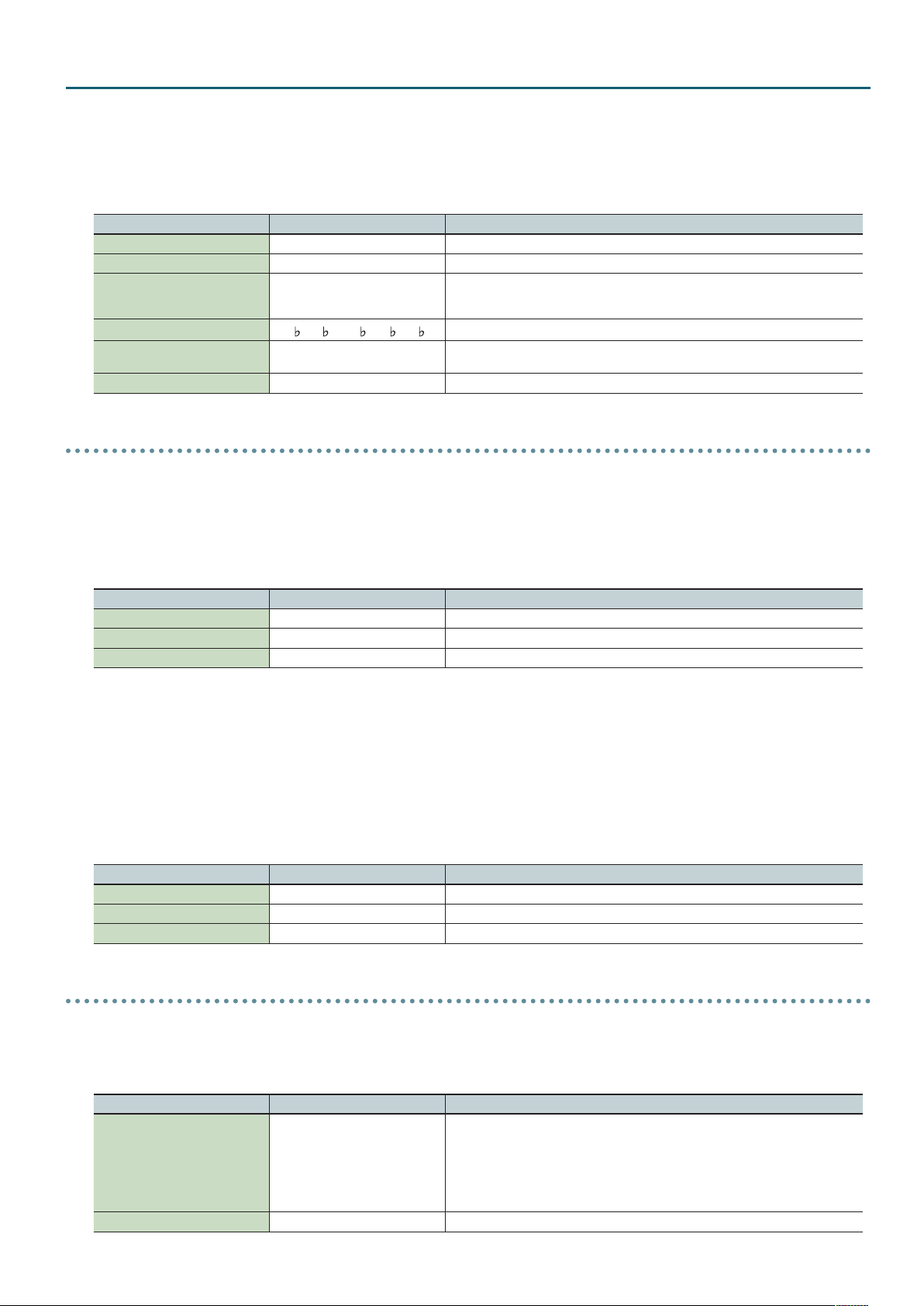
SuperNATURAL Acoustic Tone (SN-A) – INST tab
• If Bend Range is set to Tone, you can use the pitch bend lever to create glissando or fall eects.
* Moving the pitch bend lever in the upward direction will produce a glissando eect.
* Moving the pitch bend lever in the downward direction will produce a fall eect.
• If Bend Range is set to anything other than Tone, this eect will be produced if Bend Mode (CC19) is turned on. Use this when you want to switch
between glissando/fall eects and conventional pitch change.
Parameter Value Explanation
Noise Level (CC16) -64–+63 Adjusts the amount of the woodwind instrument’s breath noise or key noise.
Growl Sens (CC18) 0–127 Adjusts the distinctive nuance (growl) that occurs when a woodwind instrument is blown.
Play Scale
Scale Key
Glide Porta, Gliss
Variation Refer to p. 28. Performance variation sounds
Chroma (Chromatic), Major, Minor,
7th, Dim (Diminish), Whole (Whole
Tone)
, D, E , E, F, G , G, A , A, B , B
C, D
Produces discontinuous pitch changes according to the specied scale.
Species the key of the scale you specify for Play Scale.
Species whether portamento or glissando will be applied when the portamento switch
is on.
Recorder
ExSN2: 008 Soprano Recorder
ExSN2: 009 Alto Recorder
ExSN2: 0010 Tenor Recorder
ExSN2: 0011 Bass Recorder
• Legato playing will produce notes that are smoothly connected as if they were played with a single breath.
Parameter Value Explanation
Noise Level (CC16) -64–+63 Adjusts the amount of breath noise for the woodwind instrument.
Growl Sens (CC18) 0–127 Adjusts the distinctive nuance (growl) that occurs when a woodwind instrument is blown.
Variation Refer to p. 28. Performance variation sounds
ExSN2: 012 Ocarina SopC
ExSN2: 013 Ocarina SopF
ExSN2: 014 Ocarina Alto
ExSN2: 015 Ocarina Bass
• Legato playing will produce notes that are connected as if they were played in a single breath.
• While playing legato, a distinctive ornamental sound will be produced when you play strongly.
Parameter Value Explanation
Noise Level (CC16) -64–+63 Adjusts the amount of breath noise.
Growl Sens (CC18) 0–127 Adjusts the distinctive nuance (growl) that occurs when an instrument is blown.
Variation Refer to p. 28. Performance variation sounds
Vox/Choir
INT: 055 London Choir
INT: 056 Boys Choir
• You can obtain a wide range of expression by combining volume change produced by dynamics with the dierent variation sounds.
Parameter Value Explanation
Species how notes are sounded when Hold (CC64) is on.
If Hold Legato Mode is on, notes that were being held will go silent when you play a key.
Hold Legato Mode (CC19) OFF, ON
Variation Refer to p. 28. Performance variation sounds
For example if you play and release C major with Hold (CC64) on, the C major notes will be
held.
When you then play E major, the C major notes will go silent, and the E major notes will be
heard.
27
Page 28
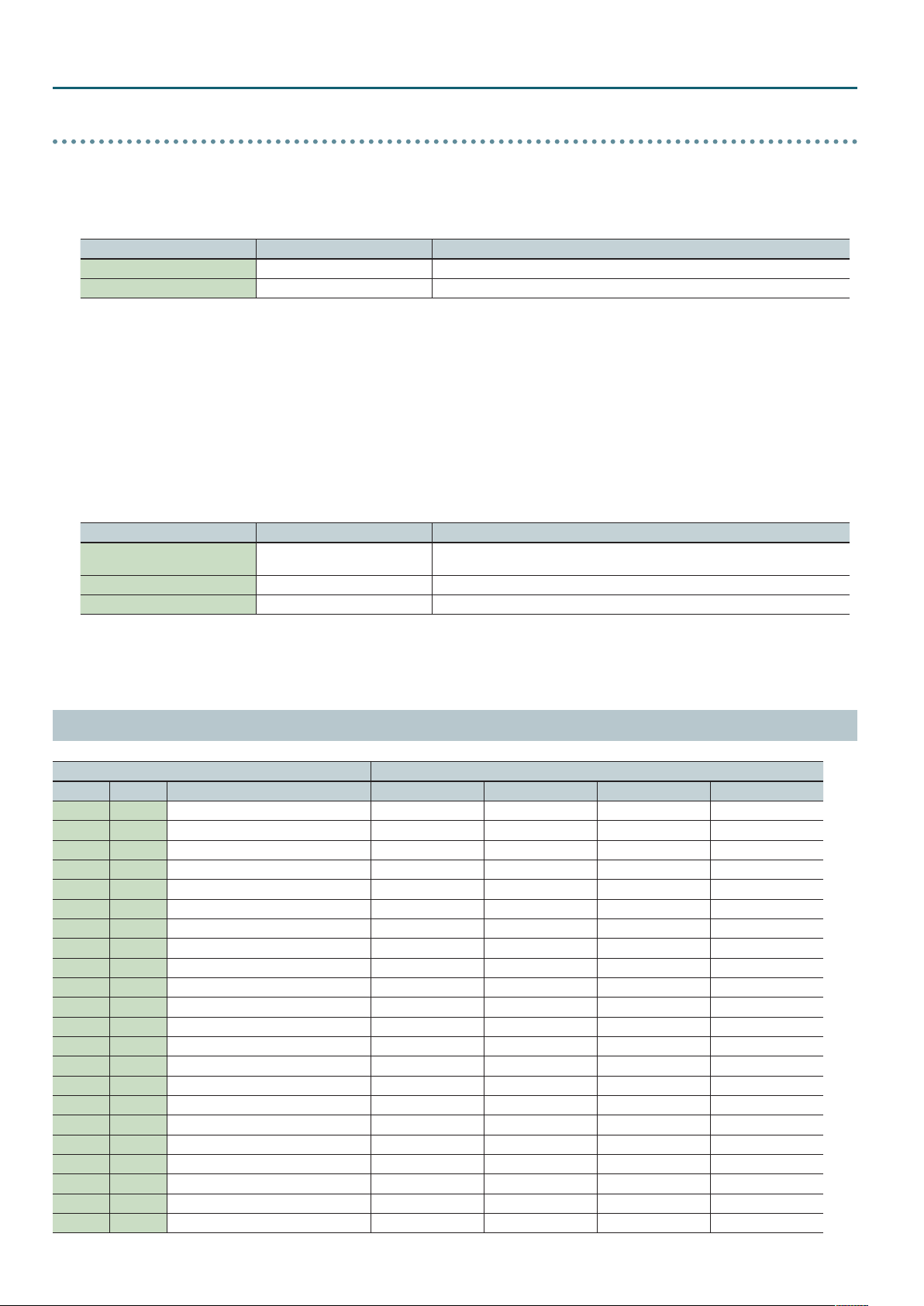
SuperNATURAL Acoustic Tone (SN-A) – INST tab
Percussion
INT: 052 Timpani
• You can play a roll by operating the Modulation controller (CC01) while playing a note.
• You can use CC18 to simulate the muting technique of using your hand to press down on the timpani.
Parameter Value Explanation
Roll Speed (CC17) -64– +63 Adjusts the speed of the roll eect.
Variation Refer to p. 28. Performance variation sounds
INT: 077 Steel Drums
• You can play a roll by operating the Modulation controller (CC01) while playing a note.
• You can produce a glissando eect by employing pitch bend while playing the keyboard, or by playing legato with the Portamento SW (CC65) turned
on.
* If Bend Range is set to Tone, you can use the pitch bend lever to produce a glissando eect.
* If Bend Range is set to anything other than Tone, this eect will be produced if Bend Mode (CC19) is turned on. Use this when you want to switch
between glissando/fall eects and conventional pitch change.
• By using CC18 you can simulate the technique of using your hand or mallet to mute the vibration (sound).
Parameter Value Explanation
Resonance Level (CC16) -64–+63
Roll Speed (CC17) -64–+63 Adjusts the speed of the roll eect.
Variation Refer to p. 28. Performance variation sounds
Adjusts the sympathetic resonance. Higher settings will increase the sympathetic
resonance.
Performance Variation Sounds
INST Variation
BANK NUM NAME 1 2 3 4
INT 1 ConcertGrand - - - -
INT 2 Grand Piano1 - - - -
INT 3 Grand Piano2 - - - -
INT 4 Grand Piano3 - - - -
INT 5 Mellow Piano - - - -
INT 6 Bright Piano - - - -
INT 7 UprightPiano - - - -
INT 8 Concert Mono - - - -
INT 9 Honky-tonk - - - -
INT 10 Pure Vintage EP1 - - - -
INT 11 Pure Vintage EP2 - - - -
INT 12 Pure Wurly - - - -
INT 13 Pure Vintage EP3 - - - -
INT 14 Old Hammer EP - - - -
INT 15 Dyno Piano - - - -
INT 16 Clav CB Flat - - - -
INT 17 Clav CA Flat - - - -
INT 18 Clav CB Medium - - - -
INT 19 Clav CA Medium - - - -
INT 20 Clav CB Brillia - - - -
INT 21 Clav CA Brillia - - - -
INT 22 Clav CB Combo - - - -
28
Page 29
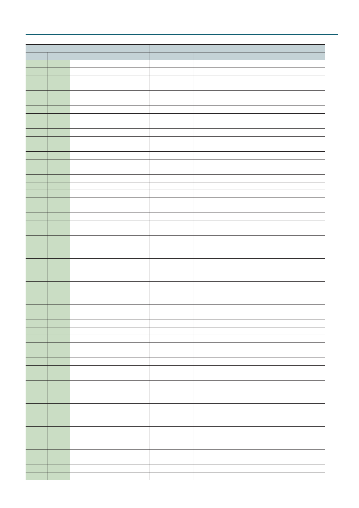
SuperNATURAL Acoustic Tone (SN-A) – INST tab
INST Variation
BANK NUM NAME 1 2 3 4
INT 23 Clav CA Combo - - - -
INT 24 Glockenspiel Dead Stroke - - -
INT 25 Vibraphone Dead Stroke Tremolo Sw - -
INT 26 Marimba Dead Stroke - - -
INT 27 Xylophone Dead Stroke - - -
INT 28 Tubular Bells Dead Stroke - - -
INT 29 TW Organ - - - -
INT 30 French Accordion - - - -
INT 31 Italian Accordion - - - -
INT 32 Harmonica - - - -
INT 33 Bandoneon - - - -
INT 34 Nylon Guitar Mute Harmonics - -
INT 35 Flamenco Guitar Rasugueado Harmonics - -
INT 36 SteelStr Guitar Mute Harmonics - -
INT 37 Jazz Guitar FingerPicking Octave Tone - -
INT 38 ST Guitar Half Mute Harmonics - -
INT 39 ST Guitar Front Mute Harmonics - -
INT 40 TC Guitar Rear Mute Harmonics - -
INT 41 Acoustic Bass Staccato Harmonics - -
INT 42 Fingered Bass Slap Harmonics - -
INT 43 Picked Bass Bridge Mute Harmonics - -
INT 44 Fretless Bass Staccato Harmonics - -
INT 45 Violin Staccato Pizzicato Tremolo -
INT 46 Violin 2 Staccato Pizzicato Tremolo -
INT 47 Viola Staccato Pizzicato Tremolo -
INT 48 Cello Staccato Pizzicato Tremolo -
INT 49 Cello 2 Staccato Pizzicato Tremolo -
INT 50 Contrabass Staccato Pizzicato Tremolo -
INT 51 Harp Nail - - -
INT 52 Timpani Flam Accent Roll - -
INT 53 Strings Staccato Pizzicato Tremolo -
INT 54 Marcato Strings Staccato Pizzicato Tremolo -
INT 55 London Choir Voice Woo - - -
INT 56 Boys Choir Voice Woo - - -
INT 57 Trumpet Staccato Fall - -
INT 58 Trombone Staccato Fall - -
INT 59 Tb2 CupMute Staccato Fall - -
INT 60 Mute Trumpet Staccato Fall - -
INT 61 French Horn Staccato - - -
INT 62 Soprano Sax 2 Staccato Fall SubTone -
INT 63 Alto Sax 2 Staccato Fall SubTone -
INT 64 Tenor Sax 2 Staccato Fall SubTone -
INT 65 Baritone Sax 2 Staccato Fall SubTone -
INT 66 Oboe Staccato - - -
INT 67 Bassoon Staccato - - -
INT 68 Clarinet Staccato - - -
INT 69 Piccolo Staccato - - -
INT 70 Flute Staccato - - -
INT 71 Pan Flute Staccato Flutter - -
INT 72 Shakuhachi Staccato Ornament - -
INT 73 Sitar - - - -
INT 74 Uilleann Pipes - Ornament - -
INT 75 Bag Pipes - Ornament - -
INT 76 Erhu Staccato Ornament - -
INT 77 Steel Drums Mute - - -
29
Page 30

SuperNATURAL Acoustic Tone (SN-A) – INST tab
INST Variation
BANK NUM NAME 1 2 3 4
ExSN1 1 Santoor Mute Tremolo - -
ExSN1 2 Yang Chin Mute Tremolo - -
ExSN1 3 Tin Whistle Cut Ornament - -
ExSN1 4 Ryuteki Staccato Ornament - -
ExSN1 5 Tsugaru Strum Up Picking Auto Bend -
ExSN1 6 Sansin Strum Up Picking Auto Bend -
ExSN1 7 Koto Tremolo Ornament - -
ExSN1 8 Taishou Koto - - - -
ExSN1 9 Kalimba Buzz - - -
ExSN1 10 Sarangi - - - -
ExSN2 1 Soprano Sax Staccato Fall SubTone -
ExSN2 2 Alto Sax Staccato Fall SubTone -
ExSN2 3 Tenor Sax Staccato Fall SubTone -
ExSN2 4 Baritone Sax Staccato Fall SubTone -
ExSN2 5 English Horn Staccato - - -
ExSN2 6 Bass Clarinet Staccato - - -
ExSN2 7 Flute2 Staccato - - -
ExSN2 8 Soprano Recorder Staccato - - -
ExSN2 9 Alto Recorder Staccato - - -
ExSN2 10 Tenor Recorder Staccato - - -
ExSN2 11 Bass Recorder Staccato - - -
ExSN2 12 Ocarina SopC Staccato Ornament - -
ExSN2 13 Ocarina SopF Staccato Ornament - -
ExSN2 14 Ocarina Alto Staccato Ornament - -
ExSN2 15 Ocarina Bass Staccato Ornament - -
ExSN3 1 TC Guitar w/Fing FingerPicking Octave Tone - -
ExSN3 2 335Guitar w/Fing FingerPicking Octave Tone - -
ExSN3 3 LP Guitar Rear Mute Harmonics - -
ExSN3 4 LP Guitar Front Mute Harmonics - -
ExSN3 5 335 Guitar Half Mute Harmonics - -
ExSN3 6 Acoustic Bass 2 Staccato Harmonics - -
ExSN3 7 Fingered Bass 2 Slap Harmonics - -
ExSN3 8 Picked Bass 2 Bridge Mute Harmonics - -
ExSN4 1 Ukulele - - - -
ExSN4 2 Nylon Guitar 2 Mute Harmonics - -
ExSN4 3 12th Steel Gtr Mute Harmonics - -
ExSN4 4 Mandolin Mute Harmonics - -
ExSN4 5 SteelFing Guitar FingerPicking Octave Tone - -
ExSN4 6 SteelStr Guitar2 Mute Harmonics - -
ExSN5 1 Classical Trumpet Staccato Fall - -
ExSN5 2 Frugal Horn Staccato Fall - -
ExSN5 3 Trumpet 2 Staccato Fall - -
ExSN5 4 Mariachi Tp Staccato Fall - -
ExSN5 5 Trombone 2 Staccato Fall - -
ExSN5 6 Bass Trombone Staccato Fall - -
ExSN5 7 Tuba Staccato - - -
ExSN5 8 Straight Mute Tp Staccato Fall - -
ExSN5 9 Cup Mute Trumpet Staccato Fall - -
ExSN5 10 French Horn 2 Staccato - - -
ExSN5 11 Mute French Horn Staccato - - -
30
Page 31

SuperNATURAL Acoustic Tone (SN-A) – MFX tab
Parameter Value Explanation
MFX tab
MFX Switch OFF, ON Switches the multi-eect (MFX) on/o.
MFX Type 0–67
Parameters for each MFX type Edit the parameters for the selected MFX type.
MFX Chorus Send Level 0–127
MFX Reverb Send Level 0–127
Use this parameter to select from among the 67 available MFXs. For details on MFX parameters,
refer to “MFX Parameters” (p. 73).
Adjusts the amount of chorus for the sound that passes through multi-eects. If you don’t want to
add the Chorus eect, set it to “0.”
* This has no eect if motional surround is on.
Adjusts the amount of reverb for the sound that passes through multi-eects. If you don’t want to
add the Reverb eect, set it to “0.”
* This has no eect if motional surround is on.
MFX CTRL tab
Sets the MIDI message used to change the multi-eects parameter with the multi-eects control.
OFF: Multi-eects control will not be used.
Source (1–4)
Destination (1–4)
Sens (1–4) -63–+63
OFF, CC01–31, 33–95, PITCH BEND,
AFTERTOUCH, SYS CTRL1–SYS CTRL4
Sets the multi-eects parameters to be controlled with the multi-eects control. The multi-eects parameters available for control will
depend on the multi-eects type. For details, refer to “MFX Parameters” (p. 73).
CC01–31, 33–95: Control Change
PITCH BEND: Pitch Bend
AFTERTOUCH: Aftertouch
SYS CTRL1–SYS CTRL4: MIDI messages used as common multi-eects controls.
Sets the amount of the multi-eects control’s eect that is applied.
To make an increase in the currently selected value (to get higher values, move to the right,
increase rates, and so on), select a positive value; to make a decrease in the currently selected value
(to get lower values, move to the left, decrease rates, and so on), select a negative value.
For either positive or negative settings, greater absolute values will allow greater amounts of
change. Set this to “0” if you don’t want to apply the eect.
31
Page 32

SuperNATURAL Synth Tone (SN-S)
TONE EDIT (SN-S)
Each tone has three sets (Partial 1–3) of OSC, FILTER, AMP, and LFO settings, in addition to multi-eect (MFX) settings.
PARTIAL 3
PARTIAL 2
PARTIAL 1
LFO
OSC FILTER
AFTERTOUCH
MOD LFO
MISC
AMP
1. In the top screen, press the [EDIT] button.
MFX
Parameter Value Explanation
COMMON tab
No assign, Ac.Piano, E.Piano, Organ,
Other Keyboards, Accordion/
Harmonica, Bell/Mallet, Ac.Guitar,
E.Guitar, Dist.Guitar, Ac.Bass, E.Bass,
Tone Category
Phrase Number 0–243 Number of the phrase that plays when you press the [VOLUME] knob (PREVIEW).
Phrase Octave Shift -3–+3 Pitch (in octave units) of the preview phrase.
Tone Level 0–127 Adjusts the overall volume of the tone.
Synth Bass, Plucked/Stroke, Strings,
Brass, Wind, Flute, Sax, Recorder, Vox/
Choir, Synth Lead, Synth Brass, Synth
Pad/Strings, Synth Bellpad, Synth
PolyKey, FX, Synth Seq/Pop, Phrase,
Pulsating, Beat&Groove, Hit, Sound
FX, Drums, Percussion, Combination
Selects the tone’s category.
32
Page 33

Parameter Value Explanation
Turns ring modulator on/o.
By multiplying partial 1’s OSC and partial 2’s OSC, this creates a complex, metallic-sounding
waveform like that of a bell.
The partial 1’s OSC waveform will change as shown in the illustration, and partial 2’s OSC will be
output with its original waveform.
Setting the partial 1 OSC and the partial 2 OSC to dierent pitches will make the ring modulator
eect more apparent.
Partial 1’s OSC
RING Switch OFF, ON
Partial 2’s OSC
Partial 1’s OSC
output waveform
If Ring Switch is turned on, the OSC Pulse Width Mod Depth, OSC Pulse Width, and SUPER SAW
Detune of partial 1 and partial 2 cannot be used.
In addition, if an asymmetrical square wave is selected as the OSC waveform, the OSC variation
will be ignored, and there will be a slight dierence in sound compared to the originally selected
waveform.
Wave Shape 0–127
Analog Feel 0–127
Unison Switch OFF, ON
Partial 1 will be modulated by the pitch of partial 2. Higher values produce a greater eect.
This has no eect if the partial 1 waveform is PW-SQR or SP-SAW.
Use this to apply “1/f uctuation,” a type of randomness or instability that is present in many
natural systems (such as a babbling brook or whispering breeze) and is perceived as pleasant by
many people.
By applying “1/f uctuation” you can create the natural-sounding instability that is characteristic
of an analog synthesizer.
This layers a single sound.
If the Unison Switch is on, the number of notes layered on one key will change according to the
number of keys you play.
Number of notes assigned to each key when the Unison Switch is on
SuperNATURAL Synth Tone (SN-S) – COMMON tab
waveform
waveform
Example: If Unison Size is 8
Unison Size 2, 4, 6, 8
Mono/Poly POLY, MONO Species whether notes will sound polyphonically (POLY) or monophonically (MONO).
Legato Switch OFF, ON
Portamento Switch OFF, ON Species whether the portamento eect will be applied (ON) or not applied (OFF).
Portamento Time 0–127
Portamento Mode NORMAL, LEGATO
Number of keys pressed Number of notes sounded
1 8
2 4 each
3–4 2 each
5–8 1 each
This is valid only if the Mono/Poly parameter is set to “MONO.” If this is on, pressing a key while the
previous key remains held down will cause the pitch to change to that of the newly pressed key
while maintaining the state in which the previous note was being sounded.
This produces an eect similar to hammering-on or pulling-o when playing a guitar.
Species the time taken for the pitch to change when playing portamento.
Higher values lengthen the time over which the pitch will change to the next note.
NORMAL: Portamento will always be applied.
LEGATO: Portamento will be applied only when you play legato (i.e., when you press the next key
before releasing the previous key).
33
Page 34

SuperNATURAL Synth Tone (SN-S) – OSC tab
Parameter Value Explanation
OSC tab
Partial Switch OFF, ON Use these buttons to turn on the partial that you want to be heard.
SAW
SQR
PW-SQR
Wave
Wave Variation A, B, C
Wave Number 1–450
Wave Gain -6, 0, +6, +12 [dB]
Pulse Width Mod Depth 0–127
Pulse Width 0–127
Pulse Width Shift 0–127
Super Saw Detune 0–127
TRI
SINE
NOISE
SUPER SAW (SP-SAW)
PCM This is a PCM waveform.
This waveform contains a sine wave fundamental plus a xed proportion of sine wave harmonics at
all integer multiples of that fundamental.
This waveform contains a sine wave fundamental plus a xed proportion of sine wave harmonics at
odd-numbered multiples of that fundamental.
The overtone structure of this waveform will vary signicantly depending on the width of the
upper portion of the waveform (Pulse Width).
This waveform contains a sine wave fundamental plus a xed proportion of sine wave harmonics at
even-numbered multiples of that fundamental.
This is a sine wave. This is a waveform that produces just a single frequency; it is the basis of all
sound.
This waveform contains all frequencies. It is suitable for percussion instrument sounds or sound
eects.
This produces a tone similar to seven sawtooth waves heard simultaneously. Pitch-shifted sounds
are added to the center sound. It is suitable for strings sounds, and for creating thick sounds.
You can select variations of the currently selected WAVE.
* This has no eect for SP-SAW or PCM.
Selects the PCM waveform.
* This is valid only if PCM is selected for OSC Wave.
Species the gain (amplitude) of the waveform.
The value will change in 6 dB (decibel) steps. Each 6 dB increase doubles the gain.
* This is valid only if PCM is selected for OSC Wave.
Species the amount (depth) of LFO applied to PW (Pulse Width).
If the OSC Wave has selected (PW-SQR), you can use this slider to specify the amount of LFO
modulation applied to PW (pulse width).
* If the Ring Switch is on, this has no eect on partials 1 and 2.
Species the pulse width.
If the OSC Wave has selected (PW-SQR), you can use this slider to specify the width of the upper
portion of the square wave (the pulse width) as a percentage of the entire cycle.
Decreasing the value will decrease the width, approaching a square wave (pulse width = 50%).
Increasing the value will increase the width, producing a distinctive sound.
* If the Ring Switch is on, this has no eect on partials 1 and 2.
Shifts the range of change. Normally, you can leave this at 127.
* If the Ring Switch is on, this has no eect on partials 1 and 2.
Species the amount of pitch dierence between the seven sawtooth waves layered within a
single oscillator.
* Higher values will increase the pitch dierence. (OSC Detune applies an equal amount of pitch
dierence between each of the seven sawtooth waves.)
* If the Ring Switch is on, this has no eect on partials 1 and 2.
* This is valid only if SP-SAW is selected for OSC Wave.
PITCH tab
OSC Pitch -24–+24 Adjusts the pitch in semitone steps.
OSC Detune -50–+50 Adjusts the pitch in steps of one cent.
Pitch Env Attack Time 0–127
Pitch Env Decay Time 0–127
Pitch Env Depth -63–+63 This species how much the pitch envelope will aect the pitch.
Octave Shift -3–+3 Species the octave of the tone.
Pitch Bend Range Up 0–+24
Pitch Bend Range Down 0–-24
Species the attack time of the pitch envelope.
This species the time from the moment you press the key until the pitch reaches its highest (or
lowest) point.
Species the decay time of the pitch envelope.
This species the time from the moment the pitch reaches its highest (or lowest) point until it
returns to the pitch of the key you pressed.
Species the amount of pitch change that occurs when the pitch bend/modulation lever is moved
all the way to the right.
Species the amount of pitch change that occurs when the pitch bend/modulation lever is moved
all the way to the left.
FILTER tab
FILTER Mode
34
BYPASS, LPF1, LPF2, LPF3, LPF4, HPF,
BPF, PKG
Selects the type of lter.
Page 35

Parameter Value Explanation
This button selects the slope (steepness) of the lter.
For the LPF
Level
SuperNATURAL Synth Tone (SN-S) – AMP tab
FILTER Slope -12, -24 [dB]
frequency
FILTER Cuto 0–127 Species the cuto frequency.
Here’s how you can make the lter cuto frequency to vary according to the key you play.
Cuto frequency
(octave)
+2
+1
FILTER Cuto KF -100–+100
FILTER Env V-Sens -63–+63
FILTER Resonance 0–127 Resonance emphasizes the sound in the region of the lter cuto frequency.
FILTER Env Attack 0–127
FILTER Env Decay 0–127
FILTER Env Sustain 0–127
FILTER Env Release 0–127
FILTER Env Depth -63–+63
0
-1
-2
C4C3C2 C5 C6
Here’s how you can make the lter envelope depth vary according to the strength with which you
play the key.
This species the time from the
moment you press the key until
the cuto frequency reaches its
highest (or lowest) point.
This species the time from when
the cuto frequency reaches its
highest (or lowest) point, until it
decays to the sustain level.
This species the cuto frequency
that will be maintained from
when the decay time has elapsed
until you release the key.
This species the time from
when you release the key until
the cuto frequency reaches its
minimum value.
This species the direction
and depth to which the cuto
frequency will change.
Species the cuto frequency of an independent -6 dB high-pass lter.
-24 dB
Cuto
frequency
Key-on
+100
+50
0
-50
-100
-12 dB
FrequencyCuto
High
Value
Low
Key
Key-o
DEPTH
Time
HPF Cuto 0–127
-6 dB HPF
BYPASS, LPF, HPF,
BPF, PKG
AMP tab
AMP Level 0–127 Partial volume.
AMP Level V-Sens -63–+63
AMP Pan L64–63R Here’s how to change the stereo position of the partial.
Here’s how you can make the volume vary according to the strength with which you play the
keyboard.
35
Page 36

SuperNATURAL Synth Tone (SN-S) – LFO tab
Parameter Value Explanation
AMP Level Keyfollow
AMP Env Attack 0–127
AMP Env Decay 0–127
AMP Env Sustain 0–127
AMP Env Release 0–127
-100, -90, -80, -70, -60, -50, -40, -30,
-20, -10, 0, +10, +20, +30, +40, +50,
+60, +70, +80, +90, +100
Specify this if you want to vary the volume according to the position of the key that you play.
With the C4 key (middle C) as the base volume, “+” values will make the volume increase as you
play above C4; “-” values will make the volume decrease. Higher values will produce greater
change.
Species the attack time of the
amp envelope.
This species the time from the
moment you press the key until
the maximum volume is reached.
Species the decay time of the
amp envelope.
This species the time from when
the maximum volume is reached,
until it decays to the sustain level.
Species the sustain level of the
amp envelope.
This species the volume level
that will be maintained from
when the attack and decay times
have elapsed until you release
the key.
Species the release time of the
amp envelope.
This species the time from
when you release the key until
the volume reaches its minimum
value.
Cuto
frequency
Key-on
Key-o
Time
LFO tab
Selects the LFO waveform.
TRI
SIN
LFO Shape
LFO Rate 0–127 Species the LFO rate when Modulation LFO Tempo Sync Switch is OFF.
LFO Tempo Sync Sw OFF, ON If this is ON, the LFO rate can be specied as a note value relative to the tempo.
LFO Tempo Sync Note
LFO Fade Time 0–127
LFO Key Trigger OFF, ON If this is on, the LFO cycle will be restarted when you press a key.
LFO Pitch Depth -63–+63 This allows the LFO to modulate the pitch, producing a vibrato eect.
LFO FILTER Depth -63–+63 This allows the LFO to modulate the FILTER CUTOFF (cuto frequency), producing a wah eect.
LFO AMP Depth -63–+63 This allows the LFO to modulate the AMP LEVEL (volume), producing a tremolo eect.
LFO Pan Depth -63–+63 Here’s how to make the PAN (stereo position) vary (Auto Panning).
SAW
SQR
S&H Sample and Hold ( The LFO value will change once each cycle.)
RND Random wave
16, 12, 8, 4, 2, 1, 3/4, 2/3, 1/2, 3/8, 1/3,
1/4, 3/16, 1/6, 1/8, 3/32, 1/12, 1/16,
1/24, 1/32
Triangle wave
Sine wave
Sawtooth wave
Square wave
Species the LFO rate when Modulation LFO Tempo Sync Switch is ON.
This species the time from when the partial sounds until the LFO reaches its maximum amplitude.
Fade Time
36
Page 37

SuperNATURAL Synth Tone (SN-S) – MOD LFO tab
Parameter Value Explanation
MOD LFO tab
Selects the MODULATION LFO waveform.
There is an LFO that is always applied to the partial, and a MODULATION LFO for applying modulation when the pitch bend/modulation
lever is moved away from yourself.
TRI
ModLFO Shape
ModLFO Rate 0–127 Species the LFO rate when Modulation LFO Tempo Sync Switch is OFF.
ModLFO TempoSyncSw OFF, ON If this is ON, the LFO rate can be specied as a note value relative to the tempo.
ModLFO TempoSyncNote
ModLFO Pitch Depth -63–+63 This allows the LFO to modulate the pitch, producing a vibrato eect.
ModLFO FILTER Depth -63–+63 This allows the LFO to modulate the FILTER CUTOFF (cuto frequency), producing a wah eect.
ModLFO AMP Depth -63–+63 This allows the LFO to modulate the AMP LEVEL (volume), producing a tremolo eect.
ModLFO Pan Depth -63–+63 Here’s how to make the PAN (stereo position) vary (Auto Panning).
ModLFO Rate Control -63–+63
SIN
SAW
SQR
S&H Sample and Hold ( The LFO value will change once each cycle.)
RND Random wave
16, 12, 8, 4, 2, 1, 3/4, 2/3, 1/2, 3/8, 1/3,
1/4, 3/16, 1/6, 1/8, 3/32, 1/12, 1/16,
1/24, 1/32
Triangle wave
Sine wave
Sawtooth wave
Square wave
Species the LFO rate when Modulation LFO Tempo Sync Switch is ON.
Make these settings if you want to change the Modulation LFO Rate when the modulation lever is
operated.
Specify a positive “+” value if you want the Modulation LFO Rate to speed up when you move the
modulation lever; specify a negative “-” value if you want it to slow down.
AFTERTOUCH tab
Cuto Aftertouch Sens -63–+63
Level Aftertouch Sens -63–+63
Species how aftertouch pressure will aect the cuto frequency.
Specify a positive “+” value if you want aftertouch to raise the cuto frequency; specify a negative
“-” value if you want aftertouch to lower the cuto frequency.
Species how aftertouch pressure will aect the volume.
Specify a positive “+” value if you want aftertouch to increase the volume; specify a negative “-”
value if you want aftertouch to decrease the volume.
MISC tab
Attack Time Interval Sens 0–127
Release Time Interval Sens 0–127
Portamento Time Interval Sens 0–127
Use this to loop the envelope between certain regions during a note-on.
Envelope Loop Mode
Attack
Decay
OFF The envelope will operate normally.
FREE-RUN
TEMPO-SYNC Species the loop rate as a note value (Sync Note parameter).
Envelope Loop Sync Note Note (p. 96)
Chromatic Portamento OFF, ON If this is turned on, portamento will operate in semitone steps.
Shortens the FILTER and AMP Attack Time according to the spacing between note-on events.
Higher values produce a greater eect. With a setting of 0, there will be no eect. This is eective
when you want to play rapid notes using a sound that has a slow attack (Attack Time).
Shortens the FILTER and AMP Release Time if the interval between one note-on and the next
note-o is brief. Higher values produce a greater eect. With a setting of 0, there will be no eect.
This is eective when you want to play staccato notes using a sound that has a slow release.
Shortens the Portamento Time according to the spacing between note-on events. Higher values
produce a greater eect. With a setting of 0, there will be no eect.
Sustain
When the Decay segment has ended, the envelope will return to the Attack. The Attack through
Decay segments will repeat until note-o occurs.
Returns to the Attack at the specied rate. If the Attack+Decay time is shorter than the specied
rate, the Sustain Level will be maintained. If the Attack+Decay time is longer than the specied
rate, the envelope will return to the Attack even though the Decay has not been completed.
This will continue repeating until note-o occurs.
37
Page 38

SuperNATURAL Synth Tone (SN-S) – MFX tab
Parameter Value Explanation
MFX tab
MFX Switch OFF, ON Species whether MFX will be used (ON) or not used (OFF).
MFX Type 0–67
Parameters for each MFX type Edit the parameters for the selected MFX type.
MFX Chorus Send Level 0–127
MFX Reverb Send Level 0–127
Use this parameter to select from among the 67 available multi-eects.
For details on multi-eects parameters, refer to “MFX Parameters” (p. 73).
Adjusts the amount of chorus for the sound that passes through multi-eects. If you don’t want to
add the Chorus eect, set it to “0.”
* This has no eect if motional surround is on.
Adjusts the amount of reverb for the sound that passes through multi-eects. If you don’t want to
add the Reverb eect, set it to “0.”
* This has no eect if motional surround is on.
MFX CTRL tab
Sets the MIDI message used to change the multi-eects parameter with the multi-eects control.
OFF: Multi-eects control will not be used.
Source (1–4)
Destination (1–4)
Sens (1–4) -63–+63
OFF, CC01–31, 33–95, PITCH BEND,
AFTERTOUCH, SYS CTRL1–SYS CTRL4
Sets the multi-eects parameters to be controlled with the multi-eects control. The multi-eects parameters available for control will
depend on the multi-eects type. For details, refer to “MFX Parameters” (p. 97).
CC01–31, 33–95: Control Change
PITCH BEND: Pitch Bend
AFTERTOUCH: Aftertouch
SYS CTRL1–SYS CTRL4: MIDI messages used as common multi-eects controls.
Sets the amount of the multi-eects control’s eect that is applied. To make an increase in the
currently selected value (to get higher values, move to the right, increase rates, and so on), select
a positive value; to make a decrease in the currently selected value (to get lower values, move to
the left, decrease rates, and so on), select a negative value. For either positive or negative settings,
greater absolute values will allow greater amounts of change. Set this to “0” if you don’t want to
apply the eect.
38
Page 39

SuperNATURAL Drum Kit (SN-D)
TONE EDIT (SN-D)
Each kit has settings for 62 drum instruments, in addition to multi-eect (MFX) settings.
You can assign a dierent note number that will sound each of the 62 partials.
For the one part specied by the Drum Comp+EQ Assign setting, you’ll be able to use six sets of compressor + equalizer units to make the sound more
consistent or to adjust the tonal character.
PARTIAL 62
PARTIAL 1
DRUM INST
COMP+EQ 1 COMP+EQ 4
COMP+EQ 2
COMP+EQ 3 COMP+EQ 6
COMP+EQ 5
MFX
1. In the top screen, press the [EDIT] button.
Parameter Value Explanation
COMMON tab
Phrase Number 0–16 Number of the phrase that plays when you press the [VOLUME] knob (PREVIEW).
Drum Kit Level 0–127 Sets the volume of the entire drum kit.
Species the volume of the drum kit resonances and the resonances of the room. This applies only
Ambience Level 0–127
for sounds whose type is Kick, Snare, Tom, and Hi-Hat.
* For some drum instruments, this will have no eect. Refer to “SuperNATURAL Drum Inst List”
(p. 41).
DRUM INST tab
Inst Bank
Inst Number 000: OFF, 001– Selects the drum inst number assigned to partial.
Level 0–127 Sets the volume of the drum inst.
Pan L64–63R Sets the pan of the drum inst.
Chorus Send Level 0–127
Reverb Send Level 0–127
Tune -120–+120 Adjusts the pitch of the drum inst.
Attack 0–100 [%] Adjusts the level and time of the attack. A setting of 100% produces the fastest attack.
Decay -63–0 Adjusts the decay time. Negative “-” settings will produce a muting eect.
Brilliance -15–+12
Variation
Dynamic Range 0–63
Stereo Width 0–127
INT,
ExSN6
(only if an expansion is loaded)
OFF, FLAM1, FLAM2, FLAM3, BUZZ1,
BUZZ2, BUZZ3, ROLL
Selects the drum inst bank assigned to partial.
INT: Internal inst bank
ExSN6: Expanded inst bank
Species the level of the signal sent to the chorus for each drum inst.
* This has no eect if motional surround is on.
Species the level of the signal sent to the reverb for each drum inst.
* This has no eect if motional surround is on.
Adjusts the brilliance of the sound. Positive “+” settings make the sound brighter, and negative “-”
settings make the sound darker.
Species performance variations such as am, buzz, or roll.
* The parameters available for editing will depend on the drum instrument. Refer to
“SuperNATURAL Drum Inst List” (p. 41).
Species the curve by which velocity will aect the volume. With a setting of 0, any velocity will
produce the maximum volume.
Adjusts the stereo width of the sound. A setting of 0 is monaural.
* For some drum instruments, this will have no eect. Refer to “SuperNATURAL Drum Inst List”
(p. 41).
39
Page 40

SuperNATURAL Drum Kit (SN-D) – COMP tab
Parameter Value Explanation
Output Assign PART, COMP+EQ1–6 Species for each drum inst how the sound will be output.
COMP tab
* COMP + EQ can be used only for the part specied by the Drum Comp+EQ Assign setting.
Comp 1–6 Switch OFF, ON Compressor on/o setting
Comp 1–6 Attack Time 0.05–50.0ms Time from when the input exceeds the threshold until compression begins
Comp 1–6 Release Time 0.05–2000ms Time from when the input falls below the threshold until compression is turned o
Comp 1–6 Threshold 0–127 Level above which compression is applied
Comp 1–6 Ratio 1:1–inf:1 Compression ratio
Comp 1–6 Output Gain 0–+24[dB] Level of the output sound
EQ tab
* COMP + EQ can be used only for the part specied by the Drum Comp+EQ Assign setting.
EQ 1–6 Switch OFF, ON Equalizer on/o setting
EQ1–6 Low Freq 200, 400 [Hz] Frequency of the low range
EQ1–6 Low Gain -15–+15 [dB] Gain of the low frequency range
EQ1–6 Mid Freq
EQ1–6 Mid Gain -15–+15 [dB] Gain of the middle frequency range
EQ1–6 Mid Q 0.5, 1.0, 2.0, 4.0, 8.0
EQ1–6 High Freq 2000, 4000, 8000 [Hz] Frequency of the high range
EQ1–6 High Gain -15–+15 [dB] Gain of the high frequency range
200, 250, 315, 400, 500, 630, 800,
1000, 1250, 1600, 2000, 2500, 3150,
4000, 5000, 6300,8000 [Hz]
Frequency of the middle range
Width of the middle frequency range
Set a higher value for Q to narrow the range to be aected.
MFX tab
MFX Switch OFF, ON Switches the multi-eect (MFX) on/o.
MFX Type 0–67
Parameters for each MFX type Make parameter settings for the selected MFX type.
MFX Chorus Send Level 0–127
MFX Reverb Send Level 0–127
Use this parameter to select from among the 67 available MFXs. For details on MFX parameters,
refer to “MFX Parameters” (p. 73).
Adjusts the amount of chorus for the sound that passes through multi-eects. If you don’t want to
add the Chorus eect, set it to “0.”
* This has no eect if motional surround is on.
Adjusts the amount of reverb for the sound that passes through multi-eects. If you don’t want to
add the Reverb eect, set it to “0.”
* This has no eect if motional surround is on.
MFX CTRL tab
Sets the MIDI message used to change the multi-eects parameter with the multi-eects control.
OFF: Multi-eects control will not be used.
Source (1–4)
Destination (1–4)
Sens (1–4) -63–+63
OFF, CC01–31, 33–95, PITCH BEND,
AFTERTOUCH, SYS CTRL1–SYS CTRL4
Sets the multi-eects parameters to be controlled with the multi-eects control. The multi-eects parameters available for control will
depend on the multi-eects type. For details, refer to “MFX Parameter” (p. 97).
CC01–31, 33–95: Control Change
PITCH BEND: Pitch Bend
AFTERTOUCH: Aftertouch
SYS CTRL1–SYS CTRL4: MIDI messages used as common multi-eects controls.
Sets the amount of the multi-eects control’s eect that is applied.
To make an increase in the currently selected value (to get higher values, move to the right,
increase rates, and so on), select a positive value; to make a decrease in the currently selected value
(to get lower values, move to the left, decrease rates, and so on), select a negative value.
For either positive or negative settings, greater absolute values will allow greater amounts of
change. Set this to “0” if you don’t want to apply the eect.
40
Page 41

SuperNATURAL Drum Kit (SN-D) – MFX CTRL tab
SuperNATURAL Drum Inst List
The following table shows support for the Ambience Level parameter of the COMMON tab and the Stereo Width parameter of the DRUM INST tab.
Variation indicates support for the performance variation in the DRUM INST tab.
Bank No. Inst Name Type
INT 1 Studio Kick Kick
INT 2 Pop Kick Kick
INT 3 Jazz Kick Kick
INT 4 Rock Kick Kick
INT 5 Studio Kick 2 Kick
INT 6 Rock Kick 2 Kick
INT 7 Orch Bass Drum Kick
INT 8 Studio Sn Snare
INT 9 Studio Sn Rim Snare
INT 10 Studio Sn XStk Snare
INT 11 Pop Sn Snare
INT 12 Pop Sn Rim Snare
INT 13 Pop Sn XStk Snare
INT 14 Jazz Sn Snare
INT 15 Jazz Sn Rim Snare
INT 16 Jazz Sn XStk Snare
INT 17 Rock Sn Snare
INT 18 Rock Sn Rim Snare
INT 19 Rock Sn XStk Snare
INT 20 Tight Sn Snare
INT 21 Tight Sn Rim Snare
INT 22 Tight Sn XStk Snare
INT 23 Studio Sn 2 Snare
INT 24 Studio Sn 2 Rim Snare
INT 25 Studio Sn 2 XStk Snare
INT 26 Rock Sn 2 Snare
INT 27 Rock Sn 2 Rim Snare
INT 28 Rock Sn 2 XStk Snare
INT 29 Brush Sn Slap Snare
INT 30 Brush Sn Tap Snare
INT 31 Brush Sn Slide Snare
INT 32 Brush Sn Swirl 1 Snare
INT 33 Brush Sn Swirl 2 Snare
INT 34 Snare CrossStk Snare
INT 35 Orch Snare Snare
INT 36 Orch Snare XStk Snare
INT 37 Pop Tom Hi Tom
INT 38 Pop Tom Mid Tom
INT 39 Pop Tom Flr Tom
INT 40 Rock Tom Hi Tom
INT 41 Rock Tom Mid Tom
INT 42 Rock Tom Floor Tom
INT 43 Jazz Tom Hi Tom
INT 44 Jazz Tom Mid Tom
INT 45 Jazz Tom Floor Tom
INT 46 Brush Tom Hi Tom
INT 47 Brush Tom Mid Tom
INT 48 Brush Tom Floor Tom
INT 49 Med HH Close Hi-Hat
INT 50 Med HH Open Hi-Hat
Stereo
Width
ü ü
ü ü
ü ü
ü ü
ü ü
ü ü
ü ü
ü ü
ü ü
ü ü
ü ü
ü ü
ü ü
ü ü
ü ü
ü ü
ü ü
ü ü
ü ü
ü ü
ü ü
ü ü
ü ü
ü ü
ü ü
ü ü
ü ü
ü ü
ü ü
ü ü
ü ü
ü ü
ü ü
ü ü
ü ü
ü ü
ü ü
ü ü
ü ü
ü ü
ü ü
ü ü
ü ü
ü ü
ü ü
ü ü
ü ü
ü ü
ü ü
ü ü
Ambience
Level
Variation
Flam/Buzz
Flam/Buzz
Flam/Buzz
Flam/Buzz
Flam/Buzz
Flam/Buzz
Flam/Buzz
Flam/Buzz/Roll
Flam/Buzz/Roll
Flam/Buzz
Flam/Buzz/Roll
Flam/Buzz/Roll
Flam/Buzz
Flam/Buzz/Roll
Flam/Buzz/Roll
Flam/Buzz
Flam/Buzz/Roll
Flam/Buzz/Roll
Flam/Buzz
Flam/Buzz/Roll
Flam/Buzz/Roll
Flam/Buzz
Flam/Buzz/Roll
Flam/Buzz/Roll
Flam/Buzz
Flam/Buzz/Roll
Flam/Buzz/Roll
Flam/Buzz
Flam/Buzz/Roll
Flam/Buzz/Roll
Flam/Buzz
-
-
Flam/Buzz
Flam/Buzz/Roll
Flam/Buzz
Flam/Buzz
Flam/Buzz
Flam/Buzz
Flam/Buzz
Flam/Buzz
Flam/Buzz
Flam/Buzz
Flam/Buzz
Flam/Buzz
Flam/Buzz
Flam/Buzz
Flam/Buzz
Flam/Buzz
Flam/Buzz
41
Page 42

SuperNATURAL Drum Kit (SN-D) – MFX CTRL tab
Bank No. Inst Name Type
INT 51 Med HH Pedal Hi-Hat
INT 52 Standard HH Cl Hi-Hat
INT 53 Standard HH Op Hi-Hat
INT 54 Standard HH Pdl Hi-Hat
INT 55 Jazz HH Close Hi-Hat
INT 56 Jazz HH Open Hi-Hat
INT 57 Jazz HH Pedal Hi-Hat
INT 58 Brush HH Close Hi-Hat
INT 59 Brush HH Open Hi-Hat
INT 60 Standard Rd Edge Ride
INT 61 Standard Rd Bell Ride
INT 62 Std Rd Edge/Bell Ride
INT 63 Medium Ride Edge Ride
INT 64 Medium Ride Bell Ride
INT 65 Med Rd Edge/Bell Ride
INT 66 Flat 18"Ride Ride
INT 67 Brush 18"Ride Ride
INT 68 Brush 20"Ride Ride
INT 69 Standard 16"Cr R Crash
INT 70 Standard 16"Cr L Crash
INT 71 Standard 18"Cr R Crash
INT 72 Standard 18"Cr L Crash
INT 73 Jazz 16"Cr R Crash
INT 74 Jazz 16"Cr L Crash
INT 75 Heavy 18"Cr R Crash
INT 76 Heavy 18"Cr L Crash
INT 77 Brush 16"Cr R Crash
INT 78 Brush 16"Cr L Crash
INT 79 Brush 18"Cr R Crash
INT 80 Brush 18"Cr L Crash
INT 81 Splash Cymbal 1 Crash
INT 82 Splash Cymbal 2 Crash
INT 83 Brush Splash Cym Crash
INT 84 China Cymbal Crash
INT 85 Orch Cymbal Crash
INT 86 Orch Mallet Cym Crash
INT 87 Gong Crash
INT 88 Timpani F2 Percussion
INT 89 Timpani F#2 Percussion
INT 90 Timpani G2 Percussion
INT 91 Timpani G#2 Percussion
INT 92 Timpani A2 Percussion
INT 93 Timpani A#2 Percussion
INT 94 Timpani B2 Percussion
INT 95 Timpani C3 Percussion
INT 96 Timpani C#3 Percussion
INT 97 Timpani D3 Percussion
INT 98 Timpani D#3 Percussion
INT 99 Timpani E3 Percussion
INT 100 Timpani F3 Percussion
INT 101 Tambourine 1 Percussion
INT 102 Tambourine 2 Percussion - - Flam/Buzz
INT 103 Cowbell 1 Percussion
INT 104 Cowbell 2 Percussion - - Flam/Buzz
Stereo
Width
ü ü
ü ü
ü ü
ü ü
ü ü
ü ü
ü ü
ü ü
ü ü
ü
ü
ü
ü
ü
ü
ü
ü
ü
ü
ü
ü
ü
ü
ü
ü
ü
ü
ü
ü
ü
ü
ü
ü
ü
ü
ü
ü
ü
ü
ü
ü
ü
ü
ü
ü
ü
ü
ü
ü
ü
ü
ü
Ambience
Level
- Flam/Buzz
- Flam/Buzz
- Flam/Buzz
- Flam/Buzz
- Flam/Buzz
- Flam/Buzz
- Flam/Buzz
- Flam/Buzz
- Flam/Buzz
- Flam/Buzz/Roll
- Flam/Buzz/Roll
- Flam/Buzz/Roll
- Flam/Buzz/Roll
- Flam/Buzz/Roll
- Flam/Buzz/Roll
- Flam/Buzz/Roll
- Flam/Buzz/Roll
- Flam/Buzz
- Flam/Buzz
- Flam/Buzz
- Flam/Buzz
- Flam/Buzz
- Flam/Buzz
- Flam/Buzz
- Flam/Buzz
- Flam/Buzz
- Flam/Buzz/Roll
- Flam/Buzz
- Flam/Buzz
- Flam/Buzz
- Flam/Buzz
- Flam/Buzz
- Flam/Buzz
- Flam/Buzz
- Flam/Buzz
- Flam/Buzz
- Flam/Buzz
- Flam/Buzz
- Flam/Buzz
- Flam/Buzz
- Flam/Buzz
- Flam/Buzz/Roll
- Flam/Buzz
Variation
Flam/Buzz
Flam/Buzz
Flam/Buzz
Flam/Buzz
Flam/Buzz
Flam/Buzz
Flam/Buzz
Flam/Buzz
Flam/Buzz
42
Page 43

SuperNATURAL Drum Kit (SN-D) – MFX CTRL tab
Bank No. Inst Name Type
INT 105 Vibra-slap Percussion - - Flam/Buzz
INT 106 High Bongo 1 Percussion
INT 107 Low Bongo 1 Percussion
INT 108 High Bongo 2 Percussion - - Flam/Buzz
INT 109 Low Bongo 2 Percussion - - Flam/Buzz
INT 110 MuteHi Conga 1 Percussion
INT 111 OpenHi Conga 1 Percussion
INT 112 Low Conga 1 Percussion
INT 113 MuteHi Conga 2 Percussion - - Flam/Buzz
INT 114 OpenHi Conga 2 Percussion - - Flam/Buzz
INT 115 Low Conga 2 Percussion - - Flam/Buzz
INT 116 High Timbale Percussion
INT 117 Low Timbale Percussion
INT 118 High Agogo 1 Percussion
INT 119 Low Agogo 1 Percussion
INT 120 High Agogo 2 Percussion - - Flam/Buzz
INT 121 Low Agogo 2 Percussion - - Flam/Buzz
INT 122 Cabasa 1 Percussion
INT 123 Cabasa 2 Percussion - - Flam/Buzz
INT 124 Maracas 1 Percussion
INT 125 Maracas 2 Percussion - - Flam/Buzz
INT 126 Short Whistle Percussion - - Flam/Buzz
INT 127 Long Whistle Percussion - - Flam/Buzz
INT 128 Short Guiro Percussion - - Flam/Buzz
INT 129 Long Guiro Percussion - - Flam/Buzz
INT 130 Claves 1 Percussion
INT 131 Claves 2 Percussion - - Flam/Buzz
INT 132 Hi WoodBlock 1 Percussion
INT 133 Low WoodBlock 1 Percussion
INT 134 Hi WoodBlock 2 Percussion - - Flam/Buzz
INT 135 Low WoodBlock 2 Percussion - - Flam/Buzz
INT 136 Mute Cuica 1 Percussion
INT 137 Open Cuica 1 Percussion
INT 138 Mute Cuica 2 Percussion - - Flam/Buzz
INT 139 Open Cuica 2 Percussion - - Flam/Buzz
INT 140 Mute Triangle 1 Percussion - - Flam/Buzz/Roll
INT 141 Open Triangle 1 Percussion - - Flam/Buzz/Roll
INT 142 Mute Triangle 2 Percussion - - Flam/Buzz
INT 143 Open Triangle 2 Percussion - - Flam/Buzz
INT 144 Shaker Percussion - - Flam/Buzz
INT 145 Sleigh Bell 1 Percussion
INT 146 Sleigh Bell 2 Percussion - - Flam/Buzz
INT 147 Wind Chimes Percussion
INT 148 Castanets 1 Percussion
INT 149 Castanets 2 Percussion - - Flam/Buzz
INT 150 Mute Surdo 1 Percussion
INT 151 Open Surdo 1 Percussion
INT 152 Mute Surdo 2 Percussion - - Flam/Buzz
INT 153 Open Surdo 2 Percussion - - Flam/Buzz
INT 154 Sticks Other - - Flam/Buzz
INT 155 Square Click Other - - Flam/Buzz
INT 156 Metro Click Other - - Flam/Buzz
INT 157 Metro Bell Other - - Flam/Buzz
INT 158 Hand Clap Other - - Flam/Buzz
INT 159 High Q SFX - - Flam/Buzz
Stereo
Width
ü
ü
ü
ü
ü
ü
ü
ü
ü
ü
ü
ü
ü
ü
ü
ü
ü
ü
ü
ü
ü
Ambience
Level
- Flam/Buzz/Roll
- Flam/Buzz
- Flam/Buzz
- Flam/Buzz/Roll
- Flam/Buzz/Roll
- Flam/Buzz
- Flam/Buzz
- Flam/Buzz
- Flam/Buzz
- Flam/Buzz
- Flam/Buzz
- Flam/Buzz
- Flam/Buzz
- Flam/Buzz
- Flam/Buzz
- Flam/Buzz
- Flam/Buzz
- Flam/Buzz
- Flam/Buzz/Roll
- Flam/Buzz
- Flam/Buzz
Variation
43
Page 44

SuperNATURAL Drum Kit (SN-D) – MFX CTRL tab
Bank No. Inst Name Type
INT 160 Slap SFX - - Flam/Buzz
INT 161 Scratch Push SFX - - Flam/Buzz
INT 162 Scratch Pull SFX - - Flam/Buzz
INT 163 Gt Fret Noise SFX - - Flam/Buzz
INT 164 Gt Cutting Up Nz SFX - - Flam/Buzz
INT 165 Gt Cutting Dw Nz SFX - - Flam/Buzz
INT 166 AcBass Noise SFX - - Flam/Buzz
INT 167 Flute Key Click SFX - - Flam/Buzz
INT 168 Applause SFX
ExSN6 1 Laughing 1 SFX
ExSN6 2 Laughing 2 SFX
ExSN6 3 Laughing 3 SFX
ExSN6 4 Scream 1 SFX
ExSN6 5 Scream 2 SFX
ExSN6 6 Scream 3 SFX
ExSN6 7 Punch 1 SFX
ExSN6 8 Punch 2 SFX
ExSN6 9 Punch 3 SFX
ExSN6 10 Heart Beat 1 SFX
ExSN6 11 Heart Beat 2 SFX
ExSN6 12 Heart Beat 3 SFX
ExSN6 13 Foot Steps 1 SFX
ExSN6 14 Foot Steps 2 SFX
ExSN6 15 Foot Steps 3 SFX
ExSN6 16 Foot Step 1 A SFX
ExSN6 17 Foot Step 1 B SFX
ExSN6 18 Foot Step 2 A SFX
ExSN6 19 Foot Step 2 B SFX
ExSN6 20 Foot Step 3 A SFX
ExSN6 21 Foot Step 3 B SFX
ExSN6 22 Door Creaking 1 SFX
ExSN6 23 Door Creaking 2 SFX
ExSN6 24 Door Creaking 3 SFX
ExSN6 25 Door Slam 1 SFX
ExSN6 26 Door Slam 2 SFX
ExSN6 27 Door Slam 3 SFX
ExSN6 28 Scratch SFX
ExSN6 29 MetalScratch SFX
ExSN6 30 Matches SFX
ExSN6 31 Car Engine 1 SFX
ExSN6 32 Car Engine 2 SFX
ExSN6 33 Car Engine 3 SFX
ExSN6 34 Car Stop 1 L>R SFX
ExSN6 35 Car Stop 1 R>L SFX
ExSN6 36 Car Stop 2 L>R SFX
ExSN6 37 Car Stop 2 R>L SFX
ExSN6 38 Car Stop 3 L>R SFX
ExSN6 39 Car Stop 3 R>L SFX
ExSN6 40 CarPassing 1 L>R SFX
ExSN6 41 CarPassing 1 R>L SFX
ExSN6 42 CarPassing 2 L>R SFX
ExSN6 43 CarPassing 2 R>L SFX
ExSN6 44 CarPassing 3 L>R SFX
ExSN6 45 CarPassing 3 R>L SFX
ExSN6 46 CarPassing 4 SFX - - -
Stereo
Width
ü
ü
ü
ü
ü
ü
ü
ü
ü
ü
ü
ü
ü
ü
ü
ü
ü
ü
ü
ü
ü
ü
ü
ü
ü
ü
ü
ü
ü
ü
ü
ü
ü
ü
ü
ü
ü
ü
ü
ü
ü
ü
ü
ü
ü
ü
Ambience
Level
- -
- -
- -
- -
- -
- -
- -
- -
- -
- -
- -
- -
- -
- -
- -
- -
- -
- -
- -
- -
- -
- -
- -
- -
- -
- -
- -
- -
- -
- -
- -
- -
- -
- -
- -
- -
- -
- -
- -
- -
- -
- -
- -
- -
- -
- -
Variation
44
Page 45

SuperNATURAL Drum Kit (SN-D) – MFX CTRL tab
Bank No. Inst Name Type
ExSN6 47 CarPassing 5 SFX - - -
ExSN6 48 CarPassing 6 SFX - - -
ExSN6 49 Car Crash 1 L>R SFX
ExSN6 50 Car Crash 1 R>L SFX
ExSN6 51 Car Crash 2 L>R SFX
ExSN6 52 Car Crash 2 R>L SFX
ExSN6 53 Car Crash 3 L>R SFX
ExSN6 54 Car Crash 3 R>L SFX
ExSN6 55 Crash 1 SFX
ExSN6 56 Crash 2 SFX
ExSN6 57 Crash 3 SFX
ExSN6 58 Siren 1 SFX
ExSN6 59 Siren 2 L>R SFX
ExSN6 60 Siren 2 R>L SFX
ExSN6 61 Siren 3 SFX
ExSN6 62 Train 1 SFX
ExSN6 63 Train 2 SFX
ExSN6 64 Jetplane 1 L>R SFX
ExSN6 65 Jetplane 1 R>L SFX
ExSN6 66 Jetplane 2 L>R SFX
ExSN6 67 Jetplane 2 R>L SFX
ExSN6 68 Jetplane 3 L>R SFX
ExSN6 69 Jetplane 3 R>L SFX
ExSN6 70 Helicopter 1 L SFX
ExSN6 71 Helicopter 1 R SFX
ExSN6 72 Helicopter 2 L SFX
ExSN6 73 Helicopter 2 R SFX
ExSN6 74 Helicopter 3 L SFX
ExSN6 75 Helicopter 3 R SFX
ExSN6 76 Starship 1 L>R SFX
ExSN6 77 Starship 1 R>L SFX
ExSN6 78 Starship 2 L>R SFX
ExSN6 79 Starship 2 R>L SFX
ExSN6 80 Starship 3 L>R SFX
ExSN6 81 Starship 3 R>L SFX
ExSN6 82 Gun Shot 1 SFX
ExSN6 83 Gun Shot 2 SFX
ExSN6 84 Gun Shot 3 SFX
ExSN6 85 Machine Gun 1 SFX
ExSN6 86 Machine Gun 2 SFX
ExSN6 87 Machine Gun 3 SFX
ExSN6 88 Laser Gun 1 SFX
ExSN6 89 Laser Gun 2 SFX
ExSN6 90 Laser Gun 3 SFX
ExSN6 91 Explosion 1 SFX
ExSN6 92 Explosion 2 SFX
ExSN6 93 Explosion 3 SFX
ExSN6 94 Dog 1 SFX
ExSN6 95 Dog 2 SFX
ExSN6 96 Dog 3 SFX
ExSN6 97 Dog 4 SFX
ExSN6 98 Horse 1 L>R SFX
ExSN6 99 Horse 1 R>L SFX
ExSN6 100 Horse 2 L>R SFX
Stereo
Width
ü
ü
ü
ü
ü
ü
ü
ü
ü
ü
ü
ü
ü
ü
ü
ü
ü
ü
ü
ü
ü
ü
ü
ü
ü
ü
ü
ü
ü
ü
ü
ü
ü
ü
ü
ü
ü
ü
ü
ü
ü
ü
ü
ü
ü
ü
ü
ü
ü
ü
ü
ü
Ambience
Level
- -
- -
- -
- -
- -
- -
- -
- -
- -
- -
- -
- -
- -
- -
- -
- -
- -
- -
- -
- -
- -
- -
- -
- -
- -
- -
- -
- -
- -
- -
- -
- -
- -
- -
- -
- -
- -
- -
- -
- -
- -
- -
- -
- -
- -
- -
- -
- -
- -
- -
- -
- -
Variation
45
Page 46

SuperNATURAL Drum Kit (SN-D) – MFX CTRL tab
Bank No. Inst Name Type
ExSN6 101 Horse 2 R>L SFX
ExSN6 102 Horse 3 L>R SFX
ExSN6 103 Horse 3 R>L SFX
ExSN6 104 Birds 1 SFX
ExSN6 105 Birds 2 SFX
ExSN6 106 Rain 1 SFX
ExSN6 107 Rain 2 SFX
ExSN6 108 Thunder 1 SFX
ExSN6 109 Thunder 2 SFX
ExSN6 110 Thunder 3 SFX
ExSN6 111 Wind SFX
ExSN6 112 Seashore SFX
ExSN6 113 Stream 1 SFX
ExSN6 114 Stream 2 SFX
ExSN6 115 Bubbles 1 SFX
ExSN6 116 Bubbles 2 SFX
ExSN6 117 Burst 1 SFX
ExSN6 118 Burst 2 SFX
ExSN6 119 Burst 3 SFX
ExSN6 120 Burst 4 SFX - - -
ExSN6 121 Glass Burst 1 SFX
ExSN6 122 Glass Burst 2 SFX
ExSN6 123 Glass Burst 3 SFX
ExSN6 124 Telephone 1 SFX
ExSN6 125 Telephone 2 SFX
ExSN6 126 Telephone 3 SFX
Stereo
Width
ü
ü
ü
ü
ü
ü
ü
ü
ü
ü
ü
ü
ü
ü
ü
ü
ü
ü
ü
ü
ü
ü
ü
ü
ü
Ambience
Level
- -
- -
- -
- -
- -
- -
- -
- -
- -
- -
- -
- -
- -
- -
- -
- -
- -
- -
- -
- -
- -
- -
- -
- -
- -
Variation
46
Page 47

PCM Synth Tone (PCMS)
TONE EDIT (PCMS)
Each tone has settings for four sets (Partial 1–4) of WAVE, TVF, TVA, and LFO×2, in addition to multi-eect (MFX) settings.
You can create sounds by combining four partials.
Each partial can be turned on/o, allowing you to specify which partial (s) will be heard.
PARTIAL 4
PARTIAL 3
PARTIAL 2
PARTIAL 1
LFO 1
WAVE TVF
TVA
MFX
PITCH
ENV
TVF ENV TVA
ENV
LFO 2
STEP LFO
1. In the top screen, press the [EDIT] button.
MEMO
In this manual, Parameters that can be controlled using the Matrix Control (p. 63) are marked
.”
with a “
Parameter Value Explanation
COMMON tab
No assign, Ac.Piano, E.Piano, Organ,
Other Keyboards, Accordion/
Harmonica, Bell/Mallet, Ac.Guitar,
E.Guitar, Dist.Guitar, Ac.Bass, E.Bass,
Tone Category
Phrase Number 0–243 Number of the phrase that plays when you press the [VOLUME] knob (PREVIEW).
Phrase Octave Shift -3–+3 Pitch (in octave units) of the preview phrase.
Tone Level 0–127 Adjusts the overall volume of the tone.
Tone Pan L64–63R Species the pan of the tone. “L64” is far left, “0” is center, and “63R” is far right.
Tone Priority LAST, LOUDEST
Octave Shift -3–+3 Adjusts the pitch of the tone’s sound up or down in units of an octave (+/-3 octaves).
Tone Coarse Tune -48–+48 Adjusts the pitch of the patch’s sound up or down in semitone steps (+/-4 octaves).
Tone Fine Tune -50–+50
Synth Bass, Plucked/Stroke, Strings,
Brass, Wind, Flute, Sax, Recorder, Vox/
Choir, Synth Lead, Synth Brass, Synth
Pad/Strings, Synth Bellpad, Synth
PolyKey, FX, Synth Seq/Pop, Phrase,
Pulsating, Beat&Groove, Hit, Sound
FX, Drums, Percussion, Combination
Selects the tone’s category.
This determines how notes will be managed when the maximum polyphony is exceeded (128
voices).
LAST: The last-played voices will be given priority, and currently sounding notes will be turned o
in order, beginning with the rst-played note.
LOUDEST: The voices with the loudest volume will be given priority, and currently sounding notes
will be turned o, beginning with the lowest-volume voice.
Adjusts the tone of the patch’s sound up or down in 1-cent steps (+/-50 cents).
* One cent is 1/100th of a semitone.
47
Page 48

PCM Synth Tone (PCMS) – COMMON tab
Parameter Value Explanation
This setting allows you to apply “stretched tuning” to the patch. (Stretched tuning is a system
by which acoustic pianos are normally tuned, causing the lower range to be lower and the higher
range to be higher than the mathematical tuning ratios would otherwise dictate.) With a setting
of “OFF,” the patch’s tuning will be equal temperament. A setting of “3” will produce the greatest
dierence in the pitch of the low and high ranges.
The diagram shows the pitch change relative to equal temperament that will occur in the low and
high ranges. This setting will have a subtle eect on the way in which chords resonate.
Pitch dierence from
equal temperament
Stretch Tune Depth OFF, 1–3
Parameter value
3
2
1
Analog Feel 0–127
Cuto Oset -63–+63
Resonance Oset -63–+63
Attack Time Oset -63–+63
Release Time Oset -63–+63
Velocity Sens Oset -63–+63
Mono/Poly MONO, POLY
OFF
1
2
3
Low note range
OFF
High note range
Species the depth of 1/f modulation that is to be applied to the tone. (1/f modulation is a pleasant
and naturally-occurring ratio of modulation that occurs in a babbling brook or rustling wind.)
By adding this “1/f modulation,” you can simulate the natural instability characteristic of an
analog synthesizer.
Cuto Frequency Oset alters the cuto frequency of the overall tone, while preserving the
relative dierences between the cuto frequency values set for each partial in the Cuto
Frequency parameters (p. 56).
NOTE
This value is added to the cuto frequency value of a partial, so if the cuto frequency value of
any partial is already set to “127” (maximum), positive “+” settings here will not produce any
change.
Resonance Oset alters the resonance of the overall tone, while preserving the relative dierences
between the resonance values set for each partial in the Resonance parameter (p. 56).
* Resonance: emphasizes the overtones in the region of the cuto frequency, adding character
to the sound.
NOTE
This value is added to the resonance value of a partial, so if the resonance value of any partial is
already set to “127” (maximum), positive “+” settings here will not produce any change.
Attack Time Oset alters the attack time of the overall tone, while preserving the relative
dierences between the attack time values set for each partial in the TVA Env Time 1 parameters (p.
59), TVF Env Time 1 parameters (p. 58).
* Attack Time: The time it takes for a sound to reach maximum volume after the key is pressed
and sound begun.
NOTE
This value is added to the attack time value of a partial, so if the attack time value of any partial
is already set to “127” (maximum), positive “+” settings here will not produce any change.
Release Time Oset alters the release time of the overall tone, while preserving the relative
dierences between the release time values set for each partial in the TVA Env Time 4 parameters
(p. 59), TVF Env Time 4 parameters (p. 58).
* Release Time: The time from when you take your nger o the key until the sound disappears.
NOTE
This value is added to the release time value of a partial, so if the release time value of any
partial is already set to “127” (maximum), positive “+” settings here will not produce any
change.
Velocity Sensitivity Oset alters the Velocity Sensitivity of the overall tone while preserving the
relative dierences between the Velocity Sensitivity values set for each partial in the parameters
below.
Cuto Velocity Sens parameter (p. 57)
Level Velocity Sens parameter (p. 58)
* Velocity: Pressure with which the key is pressed.
NOTE
This value is added to the velocity sensitivity value of a partial, so if the velocity sensitivity
value of any partial is already set to “+63” (maximum), positive “+” settings here will not
produce any change.
Species whether the tone will play polyphonically (POLY) or monophonically (MONO). The
“MONO” setting is eective when playing a solo instrument patch such as sax or ute.
MONO: Only the last-played note will sound.
POLY: Two or more notes can be played simultaneously.
48
Page 49

Parameter Value Explanation
This setting species whether the Legato Switch will be used (ON) or not (OFF).
Legato Switch is valid when the Mono/Poly parameter is set to “MONO.” With the Legato Switch
Legato Switch OFF, ON
“ON,” pressing a key while continuing to press a previous key causes the note to change pitch to
the pitch of the most recently pressed key, sounding all the while.
This creates a smooth transition between notes, which is eective when you wish to simulate the
hammering on and pulling-o techniques used by a guitarist.
The setting determines whether sounds are replayed (ON) or not (OFF) when performing legato.
The Legato Retrigger is valid when the Mono/Poly is set to “MONO” and the Legato Switch is set to
“ON.” Normally you will leave this parameter “ON.”
When “OFF,” when one key is held down and another key is then pressed, only the pitch changes,
without the attack of the latter key being played. Set this to “OFF” when performing wind and
string phrases or when using modulation with the mono synth keyboard sound.
NOTE
Legato Retrigger OFF, ON
Portamento Switch OFF, ON
Portamento Mode NORMAL, LEGATO
Portamento Type RATE, TIME
When another key is pressed during a pitch change produced by portamento, a new pitch change will begin. This setting species the
pitch at which the change will begin.
Let’s say you have the Legato Switch set to “ON,” and the Legato Retrigger set to “OFF.”
When you try to sound a legato (by pressing a higher key while a lower key is held down), the
pitch may sometimes not be able to rise all the way to the intended pitch (stopping instead at
an intermediate pitch). This can occur because the limit of pitch rise, as determined at the wave
level, has been exceeded.
Additionally, if diering upper pitch limits are used for the waves of a tone that uses multiple
partials, it may stop being heard in MONO.
When making large pitch changes, set the Legato Retrigger to “ON.”
Species whether the portamento eect will be applied (ON) or not (OFF).
Portamento
Portamento is an eect which smoothly changes the pitch from the rst-played key to the
next-played key. By applying portamento when the Mono/Poly parameter is “MONO,” you can
simulate slide performance techniques on a violin or similar instrument.
Species the performance conditions for which portamento will be applied.
NORMAL: Portamento will always be applied.
LEGATO: Portamento will be applied only when you play legato (i.e., when you press the next key
before releasing the previous key).
Species the type of portamento eect.
RATE: The time it takes will depend on the distance between the two pitches.
TIME: The time it takes will be constant
Starts a new portamento when another key is pressed while the pitch is changing.
Pitch
PCM Synth Tone (PCMS) – COMMON tab
Portamento Start
PITCH
NOTE
C5
D4
C4
Time
press D4 key
press C5 key
press C4 key
Portamento will begin a new from the pitch where the current change would end.
Pitch
C5
D4
C4
Time
press D4 key
press C5 key
press C4 key
49
Page 50

PCM Synth Tone (PCMS) – WAVE tab
Parameter Value Explanation
Portamento Time 0–127
When portamento is used, this species the time over which the pitch will change. Higher settings
will cause the pitch change to the next note to take more time.
WAVE tab
Partial Switch OFF, ON Used to specify whether partial 1–4 will be used (ON) or not used (OFF).
Wave Group
Wave No.L (Mono)
Wave No.R
Wave Gain -6, 0, +6, +12 [dB]
Wave Tempo Sync OFF, ON
INT,
SRX01–SRX12
(only if an expansion is loaded)
OFF, 1–
Selects the group for the waveform that is to be the basis of the partial.
INT: Waveforms stored in internal
SRX01–SRX12: Expansion sound banks
Selects the basic waveform for a tone. Along with the Wave number, the Wave name appears at the
lower part of the display.
When in monaural mode, only the left side (L) is specied. When in stereo, the right side (R) is also
specied.
NOTE
If you specify only the right side (R), there will be no sound.
Sets the gain (amplication) of the waveform. The value changes in 6 dB (decibel) steps—an
increase of 6 dB doubles the waveform’s gain. If you intend to use the Booster to distort the
waveform’s sound, set this parameter to its maximum value (p. 53).
When you wish to synchronize a Phrase Loop to the clock (tempo), set this to “ON.”
This is valid only when an SRX waveform which indicates a tempo (BPM) is selected.
(Example: SRX05 3:080:BladeBtL, SRX08 5:75:BoomRvBel, etc.)
If a waveform from an SRX is selected for the partial, turning the Wave Tempo Sync parameter
“ON” will cause pitch-related settings and FXM-related settings to be ignored.
When the Wave Tempo Sync is set to “ON,” set the Partial Delay Time (p. 51) to “0.”
With other settings, a delay eect will be applied, and you will be not be able to play as you expect.
FXM Switch OFF, ON
FXM Color 1–4
FXM Depth
0–16
Phrase Loop
“Phrase” loop refers to the repeated playback of a phrase that’s been pulled out of a song (e.g., by
using a sampler). One technique involving the use of Phrase Loops is the excerpting of a Phrase
from a pre-existing song in a certain genre, for example dance music, and then creating a new
song with that Phrase used as the basic motif. This is referred to as “Break Beats.”
This sets whether FXM will be used (ON) or not (OFF).
FXM
FXM (Frequency Cross Modulation) uses a specied waveform to apply frequency modulation to
the currently selected waveform, creating complex overtones. This is useful for creating dramatic
sounds or sound eects.
Species how FXM will perform frequency modulation.
Higher settings result in a grainier sound, while lower settings result in a more metallic sound.
Species the depth of the modulation produced by FXM.
* You can use matrix control to modify this.
50
Page 51

Parameter Value Explanation
Partial Delay
This produces a time delay between the moment a key is pressed (or released), and the moment the partial actually begins to sound. You
can also make settings that shift the timing at which each partial is sounded.
This diers from the Delay in the internal eects, in that by changing the sound qualities of the delayed partials and changing the pitch
for each partial, you can also perform arpeggio-like passages just by pressing one key.
You can also synchronize the partial delay time to the tempo of the external MIDI sequencer.
NOTE
If you don’t wish to use Partial Delay, set Partial Delay Mode to “NORM” and Partial Delay Time to “0.”
• If the Structure Type set in the range of “2”–”10,” the output of partial 1 and 2 will be combined into partial 2, and the output of partial
3 and 4 will be combined into partial 4.
For this reason, partial 1 will follow the settings of partial 2, and partial 3 will follow the settings of partial 4 (p. 52).
The partial begins to play after the time specied in the Partial Delay Time parameter has elapsed.
NORM
Note on
Although the partial begins to play after the time specied in the Partial Delay Time parameter
has elapsed, if the key is released before the time specied in the Partial Delay Time parameter has
elapsed, the partial is not played.
Partial Delay Mode
HOLD
PCM Synth Tone (PCMS) – WAVE tab
No Partial Delay
Delay time
Note o
OFF-N
OFF-D
Partial Delay Time 0–127, Note
No sound
played
Note on
Delay time
Note o
Rather than being played while the key is pressed, the partial begins to play once the period of
time specied in the Partial Delay Time parameter has elapsed after release of the key. This is
eective in situations such as when simulating noises from guitars and other instruments.
Delay time
Note on
Note o
Rather than being played while the key is pressed, the partial begins to play once the period
of time specied in the Partial Delay Time parameter has elapsed after release of the key. Here,
however, changes in the TVA Envelope begin while the key is pressed, which in many cases means
that only the sound from the release portion of the envelope is heard.
Delay time
Note on
Note o
Species the time from when the key is pressed (or if the Partial Delay Mode parameter is set to
“OFF-N” or “OFF-D,” the time from when the key is released) until when the partial will sound.
If you want the time until the partial sounds to be synchronized with the tempo, specify the time
as a note value relative to the synchronization tempo.
(Example) For a tempo of 120 (120 quarter notes occur in 1 minute (60 seconds))
Value Partial Delay time
(half note)
(quarter note)
(eighth note)
1 second (60/60 = 1 [second])
0.5 seconds (60/120 = 0.5 [second])
0.25 seconds (60/240 = 0.25 [second])
51
Page 52

PCM Synth Tone (PCMS) – PMT tab
Parameter Value Explanation
PMT tab
Determines how partial 1 and 2, or partial 3 and 4 are connected.
The following 10 dierent types of combination are available.
TYPE 1
PARTIAL 1 (3)
Partial 2 (4)
WG
WG
TVF TVA
With this type, partial 1 and 2 (or 3 and 4) are
TVATVF
independent. Use this type when you want to
preserve PCM sounds or create and combine sounds
for each partial.
Structure Type 1 & 2
Structure Type 3 & 4
1–10
TYPE 2
PARTIAL 1 (3)
PARTIAL
2 (4)
TYPE 3
PARTIAL 1 (3)
PARTIAL 2 (4)
TYPE 4
PARTIAL1 (3)
PARTIAL 2 (4)
TYPE 5
PARTIAL1 (3)
PARTIAL 2 (4)
TYPE 6
PARTIAL1 (3)
PARTIAL 2 (4)
TYPE 7
PARTIAL1 (3)
PARTIAL 2 (4)
WG
TVA
WG
TVA TVFWG
WG
WG
TVA TVF
WG
TVA TVFWG
WG
TVA TVFWG
WG
WG
WG
TVF
B
B
R: Ring Modulator
R
R: Ring Modulator
R
R: Ring Modulator
TVATVF
R
TVF TVA
B: Booster
TVF TVA
B: Booster
TVF TVA
TVF TVA
TVF TVA
TVF TVA
This type stacks the two lters together to intensify
the characteristics of the lters. The TVA for partial 1
(or 3) controls the volume balance between the two
partials.
This type mixes the sound of partial 1 (3) and partial
2 (4), applies a lter, and then applies a booster to
distort the waveform.
This type applies a booster to distort the waveform,
and then combines the two lters. The TVA for partial
1 (or 3) controls the volume balance between the two
partials and adjusts booster level.
This type uses a ring modulator to create new
overtones, and combines the two lters. The partial
1 (3) TVA will control the volume balance of the two
partials, adjusting the depth of ring modulator.
This type uses a ring modulator to create new
overtones, and in addition mixes in the sound of
partial 2 (4) and stacks the two lters. Since the
ring-modulated sound can be mixed with partial 2
(4), partial 1 (3) TVA can adjust the amount of the
ring-modulated sound.
This type applies a lter to partial 1 (3) and
ring-modulates it with partial 2 (4) to create new
overtones.
52
TYPE 8
PARTIAL1 (3)
PARTIAL 2 (4)
TYPE 9
PARTIAL1 (3)
PARTIAL 2 (4)
TYPE 10
PARTIAL 1 (3)
PARTIAL 2 (4)
R: Ring Modulator
WG
TVATVF
WG
R: Ring Modulator
WG
TVATVF
WG
TVF TVA
R: Ring Modulator
WG
TVATVF
WG
TVF TVA
R
R
R
TVF TVA
This type sends the ltered partial 1 (3) and partial 2
(4) through a ring modulator, and then mixes in the
sound of partial 2 (4) and applies a lter to the result.
This type passes the ltered sound of each partial
through a ring modulator to create new overtones.
The partial 1 (3) TVA will control the volume balance
of the two partials, adjusting the depth of ring
modulator.
This type passes the ltered sound of each partial
through a ring modulator to create new overtones,
and also mixes in the sound of partial 2 (4). Since the
ring-modulated sound can be mixed with partial 2
(4), partial 1 (3) TVA can adjust the amount of the
ring-modulated sound.
Page 53

Parameter Value Explanation
When a Structure Type of TYPE 3 or TYPE 4 is selected, you can adjust the depth of the booster. The
booster increases the input signal in order to distort the sound. This creates the distortion eect
frequently used with electric guitars. Higher settings will produce more distortion.
PCM Synth Tone (PCMS) – PMT tab
Booster
The Booster is used to distort the
incoming signal.
In addition to using this to create
distortion, you can use the waveform
(WG1) of one of the partials as an
LFO which shifts the other waveform
Booster 1 & 2
Booster 3 & 4
Key Fade Upper 0–127
Key Range Upper LOWER–G9 Species the highest note that the tone will sound for each partial.
0, +6, +12, +18 [dB]
Level
Fade Lower
Range Lower
(WG2) upward or downward to create
modulation similar to PWM (pulse width
modulation). This parameter works best
when you use it in conjunction with the
Wave Gain parameter (p. 50).
Fade Upper
Range Upper
This determines what will happen to the tone’s level when a note that’s higher than the partial’s
specied keyboard range is played. Higher settings produce a more gradual change in volume.
If you don’t want the tone to sound at all when a note above the keyboard range is played, set this
parameter to “0.”
Species the lowest note that the tone will sound for each partial.
Booster level
Uses WG1 as LFO
WG1
TVA
WG2
WG2
Adds to WG1
Shift in waveform by WG1
Pitch
Adjusts WG1 output
Booster
Distorted area of the
Waveform changes
Key Range Lower C-1–UPPER
Key Fade Lower 0–127
PMT Velocity Control OFF, ON, RANDOM, CYCLE
NOTE
If you attempt to raise the lower key higher than the upper key, or to lower the upper key
below the lower key, the other value will be automatically modied to the same setting.
This determines what will happen to the tone’s level when a note that’s lower than the partial’s
specied keyboard range is played. Higher settings produce a more gradual change in volume.
If you don’t want the tone to sound at all when a note below the keyboard range is played, set this
parameter to “0.”
PMT Velocity Control determines whether a dierent partial is played (ON) or not (OFF) depending
on the force with which the key is played (velocity).
When set to “RANDOM,” the tone’s constituent partials will sound randomly, regardless of any
Velocity messages.
When set to “CYCLE,” the tone’s constituent partials will sound consecutively, regardless of any
Velocity messages.
MEMO
Use “Velo Range Lower” (p. 54) and “Velo Range Upper” (p. 54) to specify the range of keyboard
dynamics.
NOTE
• If Velocity Range Lower and Velocity Range Upper are set to the same values, you won’t be able
to obtain any eect by setting PMT Velocity Control to “RANDOM” or “CYCLE.”
* Instead of using Velocity, you can also have partials substituted using the Matrix Control (p. 63).
However, the keyboard velocity and the Matrix Control cannot be used simultaneously to make
dierent partials to sound. When using the Matrix Control to switch partials, set the Velocity
Control parameter to “OFF.”
53
Page 54

PCM Synth Tone (PCMS) – PITCH tab
Parameter Value Explanation
Level
Velocity
Velo Fade Upper 0–127
Velo Range Upper LOWER–127
Velo Range Lower 1–UPPER
Velo Fade Lower 0–127
PMT Control Switch OFF, ON
Fade Lower
Range Lower
Fade Upper
Range Upper
This determines what will happen to the tone’s level when the tone is played at a velocity greater
than its specied velocity range.
Higher settings produce a more gradual change in volume.
If you want notes played outside the specied key velocity range to not be sounded at all, set this
to “0.”
This sets the highest velocity at which the partial will sound. Make these settings when you want
dierent partials to sound in response to notes played at dierent strengths.
This sets the lowest velocity at which the partial will sound. Make these settings when you want
dierent partial to sound in response to notes played at dierent strengths.
NOTE
If you attempt to set the Lower velocity limit above the Upper, or the Upper below the Lower,
the other value will automatically be adjusted to the same setting.
When using the Matrix Control (p. 63) to have dierent partials played, set the lowest value
(Lower) and highest value (Upper) of the value of the MIDI message used.
This determines what will happen to the tone’s level when the tone is played at a velocity lower
than its specied velocity range.
Higher settings produce a more gradual change in volume.
If you want notes played outside the specied key velocity range to not be sounded at all, set this
to “0.”
Use the Matrix Control (p. 63) to enable (ON), or disable (OFF) sounding of dierent partials.
NOTE
You can also cause dierent partials to sound in response to notes played at dierent strengths
(velocity) on the keyboard (p. 53). However, the Matrix Control and the keyboard velocity cannot
be used simultaneously to make dierent partials to sound.
When using the Matrix Control to have dierent partials to sound, set the Velocity Control
parameter (p. 53) to “OFF.”
PITCH tab
Partial Coarse Tune
Partial Fine Tune
Random Pitch Depth
Pitch Keyfollow -200–+200
-48–+48
-50–+50
0, 1, 2, 3, 4, 5, 6, 7, 8, 9, 10, 20, 30,
40, 50, 60, 70, 80, 90, 100, 200, 300,
400, 500, 600, 700, 800, 900, 1000,
1100, 1200
Adjusts the pitch of the partial’s sound up or down in semitone steps (+/-4 octaves).
* You can control this parameter using the Matrix Control.
Adjusts the pitch of the partial’s sound up or down in 1-cent steps (+/-50 cents).
* You can control this parameter using the Matrix Control.
* One cent is 1/100th of a semitone.
This species the width of random pitch deviation that will occur each time a key is pressed. If
you do not want the pitch to change randomly, set this to “0.” These values are in units of cents
(1/100th of a semitone).
This species the amount of pitch change that will occur when you play a key one octave higher
(i.e., 12 keys upward on the keyboard).
If you want the pitch to rise one octave as on a conventional keyboard, set this to “+100.” If you
want the pitch to rise two octaves, set this to “+200.” Conversely, set this to a negative value if you
want the pitch to fall. With a setting of “0,” all keys will produce the same pitch.
Pitch
+200
C4C3C2C1 C5 C6 C7
+100
+50
0
-50
-100-200
Key
54
Page 55

Parameter Value Explanation
Pitch Bend Range Up 0–+48
Pitch Bend Range Down 0–-48
Species the degree of pitch change in semitones when the Pitch Bend lever is all the way right.
For example, if this parameter is set to “12,” the pitch will rise one octave when the pitch bend
lever is moved to the right-most position.
Species the degree of pitch change in semitones when the Pitch Bend lever is all the way left. For
example if this is set to “-48” and you move the pitch bend lever all the way to the left, the pitch
will fall 4 octaves.
PITCH ENV tab
Pitch Env Depth -12–+12
Pitch Env V-Sens -63–+63
Pitch Env T1 V-Sens -63–+63
Pitch Env T4 V-Sens -63–+63
Adjusts the eect of the Pitch Envelope. Higher settings will cause the pitch envelope to produce
greater change. Negative “-” settings will invert the shape of the envelope.
Keyboard playing dynamics can be used to control the depth of the pitch envelope. If you want
the pitch envelope to have more eect for strongly played notes, set this parameter to a positive
“+” value. If you want the pitch envelope to have less eect for strongly played notes, set this to a
negative “-” value.
This allows keyboard dynamics to aect the Time 1 of the Pitch envelope. If you want Time 1 to be
speeded up for strongly played notes, set this parameter to a positive “+” value. If you want it to be
slowed down, set this to a negative “-” value.
Use this parameter when you want key release speed to aect the Time 4 value of the pitch
envelope. If you want Time 4 to be speeded up for quickly released notes, set this parameter to a
positive “+” value. If you want it to be slowed down, set this to a negative “-” value.
Use this setting if you want the pitch envelope times (Time 2–Time 4) to be aected by the
keyboard location. Based on the pitch envelope times for the C4 key, positive “+” settings will
cause notes higher than C4 to have increasingly shorter times, and negative “-” settings will cause
them to have increasingly longer times. Larger settings will produce greater change.
Time
PCM Synth Tone (PCMS) – PITCH ENV tab
-100
Pitch Env Time KF -100–+100
Pitch Env Time 1–4
0–127
-50
0
+50
+100
C4C3C2C1 C5 C6 C7
Specify the pitch envelope times (Time 1–Time 4).
Higher settings will result in a longer time until the next pitch is reached. (For example, Time 2 is
the time over which the pitch changes from Level 1 to Level 2.)
* You can control this parameter using the Matrix Control.
T1 T2 T3 T4
Pitch
L0
L1
Note on
T: Time L: Level
L3
Note o
L2
Key
Time
L4
Pitch Env Level 0–4 -63–+63
Specify the pitch envelope levels (Level 0–Level 4). It determines how much the pitch changes
from the reference pitch (the value set with Coarse Tune or Fine Tune on the Pitch screen) at each
point. Positive “+” settings will cause the pitch to be higher than the standard pitch, and negative
“-” settings will cause it to be lower.
55
Page 56

PCM Synth Tone (PCMS) – TVF tab
Parameter Value Explanation
TVF tab
Selects the type of lter.
A lter cuts or boosts a specic frequency region to change a sound’s brightness, thickness, or other qualities.
OFF No lter is used.
Low Pass Filter. This reduces the volume of all frequencies above the cuto frequency (Cuto Freq)
in order to round o, or un-brighten the sound.
This is the most common lter used in synthesizers.
Band Pass Filter. This leaves only the frequencies in the region of the cuto frequency (Cuto Freq),
and cuts the rest. This can be useful when creating distinctive sounds.
High Pass Filter. This cuts the frequencies in the region below the cuto frequency (Cuto Freq).
This is suitable for creating percussive sounds emphasizing their higher tones.
Peaking Filter. This emphasizes the frequencies in the region of the cuto frequency (Cuto Freq).
You can use this to create wah-wah eects by employing an LFO to change the cuto frequency
cyclically.
Low Pass Filter 2. Although frequency components above the Cuto frequency (Cuto Freq) are
cut, the sensitivity of this lter is half that of the LPF.
This makes it a comparatively warmer low pass lter.
This lter is good for use with simulated instrument sounds such as the acoustic piano.
* If you set “LPF2,” the setting for the Resonance parameter will be ignored (p. 56).
Low Pass Filter 3. Although frequency components above the Cuto frequency (Cuto Freq) are
cut, the sensitivity of this lter changes according to the Cuto frequency. While this lter is also
good for use with simulated acoustic instrument sounds, the nuance it exhibits diers from that of
the LPF2, even with the same TVF Envelope settings.
* If you set “LPF3,” the setting for the Resonance parameter will be ignored (p. 56).
Selects the frequency at which the lter begins to have an eect on the waveform’s frequency
components.
With “LPF/LPF2/LPF3” selected for the Filter Type parameter, lower cuto frequency settings
reduce a tone’s upper harmonics for a more rounded, warmer sound. Higher settings make it
sound brighter.
If “BPF” is selected, harmonic components will change depending on the TVF Cuto Frequency
setting. This can be useful when creating distinctive sounds.
With “HPF” selected, higher Cuto Frequency settings will reduce lower harmonics to emphasize
just the brighter components of the sound.
With “PKG” selected, the harmonics to be emphasized will vary depending on Cuto Frequency
setting.
* You can control this parameter using the Matrix Control.
MEMO
To edit the overall tone while preserving the relative dierences in the Cuto Frequency values
set for each partial, set the Cuto Oset parameter (p. 48).
Emphasizes the portion of the sound in the region of the cuto frequency, adding character to the
sound. Excessively high settings can produce oscillation, causing the sound to distort.
* You can control this parameter using the Matrix Control.
MEMO
To edit the overall tone while preserving the relative dierences in the Resonance values set for
each partial, set the Resonance Oset parameter (p. 48).
Filter Type
Cuto Frequency
LPF
BPF
HPF
PKG
LPF2
LPF3
0–127
Resonance
56
0–127
LPF BPF HPF PKG
Level
High
Frequency
Cuto Frequency
parameter value
Low
Page 57

Parameter Value Explanation
Use this parameter if you want the cuto frequency to change according to the key that is pressed.
Relative to the cuto frequency at the C4 key (center C), positive “+” settings will cause the cuto
frequency to rise for notes higher than C4, and negative “-” settings will cause the cuto frequency
to fall for notes higher than C4.
Larger settings will produce greater change.
Cuto frequency
(Octave)
+2
Cuto Keyfollow -200–+200
+1
PCM Synth Tone (PCMS) – TVF ENV tab
+200
+100
+50
Cuto V-Curve FIXED, 1–7
Cuto V-Sens -63–+63
Resonance V-Sens -63–+63
o
-1
-2
C4C3C2C1 C5 C6 C7
Selects one of the following seven curves that determine how keyboard playing dynamics
(velocity) inuence the cuto frequency. Set this to “FIXED” if you don’t want the Cuto frequency
to be aected by the keyboard velocity.
0
-50
-100-200
Key
1 2 3 4 5 6 7
Use this parameter when changing the cuto frequency to be applied as a result of changes in
playing velocity. If you want strongly played notes to raise the cuto frequency, set this parameter
to positive “+” settings. If you want strongly played notes to lower the cuto frequency, use
negative “-” settings.
MEMO
To edit the overall tone while preserving the relative dierences in the Cuto V-Sens values set
for each partial, set the Velocity Sens Oset parameter (p. 48). However, this setting is shared by
the Level V-Sens parameter (p. 58).
This allows keyboard velocity to modify the amount of Resonance. If you want strongly played
notes to have a greater Resonance eect, set this parameter to positive “+” settings. If you want
strongly played notes to have less Resonance, use negative “-” settings.
TVF ENV tab
TVF Env Depth -63–+63
TVF Env V-Curve FIXED, 1–7
TVF Env V-Sens -63–+63
TVF Env T1 V-Sens -63–+63
TVF Env T4 V-Sens -63–+63
Species the depth of the TVF envelope. Higher settings will cause the TVF envelope to produce
greater change. Negative “-” settings will invert the shape of the envelope.
Selects one of the following 7 curves that will determine how keyboard playing dynamics will
aect the TVF envelope. Set this to “FIXED” if you don’t want the TVF Envelope to be aected by
the keyboard velocity.
1 2 3 4 5 6 7
Species how keyboard playing dynamics will aect the depth of the TVF envelope. Positive
“+” settings will cause the TVF envelope to have a greater eect for strongly played notes, and
negative “-” settings will cause the eect to be less.
This allows keyboard dynamics to aect the Time 1 of the TVF envelope. If you want Time 1 to be
speeded up for strongly played notes, set this parameter to a positive “+” value. If you want it to be
slowed down, set this to a negative “-” value.
The parameter to use when you want key release speed to control the Time 4 value of the TVF
envelope. If you want Time 4 to be speeded up for quickly released notes, set this parameter to a
positive “+” value. If you want it to be slowed down, set this to a negative “-” value.
57
Page 58

PCM Synth Tone (PCMS) – TVA tab
Parameter Value Explanation
Use this setting if you want the TVF envelope times (Time 2–Time 4) to be aected by the keyboard
location. Based on the TVF envelope times for the C4 key (center C), positive “+” settings will cause
notes higher than C4 to have increasingly shorter times, and negative “-” settings will cause them
to have increasingly longer times. Larger settings will produce greater change.
Time
TVF Env Time KF -100–+100
Specify the TVF envelope times (Time 1–Time 4). Higher settings will lengthen the time until the
next cuto frequency level is reached. (For example, Time 2 is the time over which Level 1 will
change to Level 2.)
* You can control this parameter using the Matrix Control.
C4C3C2C1 C5 C6 C7
T1 T2 T3 T4
-100
-50
0
+50
+100
Key
TVF Env Time 1–4
TVF Env Level 0-4 0–127
0–127
Cuto
Frequency
Specify the TVF envelope levels (Level 0–Level 4). These settings specify how the cuto frequency
will change at each point, relative to the standard cuto frequency (the cuto frequency value
specied in the TVF screen).
L0
L1
Note on
T: Time L: Level
L3
L2 L4
Note o
TVA tab
Sets the volume of the partial. This setting is useful primarily for adjusting the volume balance
Partial Level
Level V-Curve FIXED, 1–7
Level V-Sens -63–+63
Bias Level -100–+100
Bias Position C-1–G9 Species the key relative to which the volume will be modied.
Bias Direction
0–127
Selects the direction in which change will occur starting from the Bias Position.
LWR The volume will be modied for the keyboard area below the Bias Point.
UPR The volume will be modied for the keyboard area above the Bias Point.
L&U The volume will be modied symmetrically toward the left and right of the Bias Point.
ALL The volume changes linearly with the bias point at the center.
between partials.
* You can control this parameter using the Matrix Control.
You can select from seven curves that determine how keyboard playing strength will aect the
volume. If you do not want the volume of the partial to be aected by the force with which you
play the key, set this to “FIXED.”
1 2 3 4 5 6 7
Set this when you want the volume of the partial to change depending on the force with which
you press the keys. Set this to a positive “+” value to have the changes in partial volume increase
the more forcefully the keys are played; to make the partial play more softly as you play harder, set
this to a negative “-” value.
MEMO
If you wish to make adjustments to the entire tone while maintaining the relative values of
TVA Level V-Sens among partials, adjust the Velocity Sens Oset parameter (p. 48). However, this
setting is shared by the Cuto V-Sens parameter (p. 57).
Adjusts the angle of the volume change that will occur in the selected Bias Direction. Larger
settings will produce greater change.
Negative “-” values will invert the change direction.
Time
58
Page 59

Parameter Value Explanation
Partial Pan
Pan Keyfollow -100–+100
L64–63R
Sets the pan of the partial. “L64” is far left, “0” is center, and “63R” is far right.
* You can control this parameter using the Matrix Control.
Use this parameter if you want key position to aect panning. Positive “+” settings will cause notes
higher than C4 key (center C) to be panned increasingly further toward the right, and negative
“-” settings will cause notes higher than C4 key (center C) to be panned toward the left. Larger
settings will produce greater change.
Pan
R
o
PCM Synth Tone (PCMS) – TVA ENV tab
+100
+50
0
-50
Random Pan Depth 0–63
Alternate Pan Depth L63–63R
TVA ENV tab
TVA Env T1 V-Sens -63–+63
TVA Env T4 V-Sens -63–+63
L
Use this parameter when you want the stereo location to change randomly each time you press a
key. Higher settings will produce a greater amount of change.
This setting causes panning to be alternated between left and right each time a key is pressed.
Higher settings will produce a greater amount of change. “L” or “R” settings will reverse the order
in which the pan will alternate between left and right. For example if two tones are set to “L” and
“R” respectively, the panning of the two tones will alternate each time they are played.
C4C3C2C1 C5 C6 C7
-100
Key
NOTE
In the Pan Key Follow, Random Pan Depth, Alternate Pan Depth parameter settings, if the
Structure Type set in the range of “2”–”10,” the output of partial 1 and 2 will be combined into
partial 2, and the output of partial 3 and 4 will be combined into partial 4.
For this reason, partial 1 will follow the settings of partial 2, and partial 3 will follow the settings
of partial 4 (p. 52).
This allows keyboard dynamics to aect the Time 1 of the TVA envelope. If you want Time 1 to be
speeded up for strongly played notes, set this parameter to a positive “+” value. If you want it to be
slowed down, set this to a negative “-” value.
The parameter to use when you want key release speed to control the Time 4 value of the TVA
envelope. If you want Time 4 to be speeded up for quickly released notes, set this parameter to a
positive “+” value. If you want it to be slowed down, set this to a negative “-” value.
Use this setting if you want the TVA envelope times (Time 2–Time 4) to be aected by the keyboard
location. Based on the TVA envelope times for the C4 key (center C), positive “+” settings will cause
notes higher than C4 to have increasingly shorter times, and negative “-” settings will cause them
to have increasingly longer times. Larger settings will produce greater change.
Time
-100
TVA Env Time KF -100–+100
TVA Env Time 1–4
0–127
-50
0
+50
+100
C4C3C2C1 C5 C6 C7
Specify the TVA envelope times (Time 1– Time 4). Higher settings will lengthen the time until the
next volume level is reached. (For example, Time 2 is the time over which Level 1 will change to
Level 2.)
* You can control this parameter using the Matrix Control.
Key
59
Page 60

PCM Synth Tone (PCMS) – OUTPUT tab
Parameter Value Explanation
Specify the TVA envelope levels (Level 1–Level 3). These settings specify how the volume will
change at each point, relative to the standard volume (the Partial Level value specied in the TVA
screen).
TVA Env Level 1–3 0–127
T1 T2 T3 T4
Level
L2
L1
Note on
T: Time L: Level
L3
Note o
Time
OUTPUT tab
Output Level 0–127 Species the signal level of each partial.
Chorus Send Level 0–127 Species the level of the signal sent to the chorus for each partial.
Reverb Send Level 0–127 Species the level of the signal sent to the reverb for each partial.
LFO1/LFO2 tab
An LFO (Low Frequency Oscillator) causes change over a cycle in a sound. Each partial has two LFOs (LFO1/LFO2), and these can be used to cyclically change the pitch, cuto
frequency and volume to create modulation-type eects such as vibrato, wah and tremolo. Both LFOs have the same parameters.
Selects the waveform of the LFO.
SIN Sine wave
TRI Triangle wave
SAW-U Sawtooth wave
SAW-D Sawtooth wave (negative polarity)
SQR Square wave
RND Random wave
Once the attack of the waveform output by the LFO is allowed to develop in standard fashion, the
BND-U
Waveform
BND-D
TRP Trapezoidal wave
S&H Sample & Hold wave (one time per cycle, LFO value is changed)
CHAOS Chaos wave
VSIN Modied sine wave. The amplitude of a sine wave is randomly varied once each cycle.
STEP
waveform then continues without further change.
NOTE
You must turn the Key Trigger parameter to “ON.” If this is “OFF,” it will have no eect.
Once the decay of the waveform output by the LFO is allowed to develop in standard fashion, the
waveform then continues without further change.
NOTE
You must turn the Key Trigger parameter to “ON.” If this is “OFF,” it will have no eect.
A waveform generated by the data specied by LFO Step 1–64. This produces stepped change with
a xed pattern similar to a step modulator.
Adjusts the modulation rate, or speed, of the LFO.
If you want the LFO rate to be synchronized with the tempo, specify the setting as a note value
relative to the synchronization tempo.
* You can control this parameter using the Matrix Control.
Rate
Rate Detune 0–127
0–127, Note
60
(Example) For a tempo of 120 (120 quarter notes occur in 1 minute (60 seconds))
Value LFO Rate
(half note)
(quarter note)
(eighth note)
1 second (60/60 = 1 [second])
0.5 seconds (60/120 = 0.5 [second])
0.25 seconds (60/240 = 0.25 [second])
NOTE
This setting will be ignored if the Waveform parameter is set to “CHAOS.”
LFO Rate Detune makes subtle changes in the LFO cycle rate (Rate parameter) each time a key is
pressed.
Higher settings will cause greater change. This parameter is invalid when Rate is set to “note.”
Page 61

Parameter Value Explanation
Oset -100, -50, 0, +50, +100
Delay Time 0–127
Raises or lowers the LFO waveform relative to the central value (pitch or cuto frequency). Positive “+”
settings will move the waveform so that modulation will occur from the central value upward. Negative
“-” settings will move the waveform so that modulation will occur from the central value downward.
Delay Time (LFO Delay Time) species the time elapsed before the LFO eect is applied (the eect
continues) after the key is pressed (or released).
* After referring to “How to Apply the LFO” (p. 62), change the setting until the desired eect is
achieved.
MEMO
When using violin, wind, or certain other instrument sounds in a performance, rather than
having vibrato added immediately after the sounds are played, it can be eective to add the
vibrato after the note is drawn out somewhat. If you set the Delay Time in conjunction with the
Pitch Depth parameter and Rate parameter, the vibrato will be applied automatically following
a certain interval after the key is pressed. This eect is called “Delay Vibrato.”
Adjusts the value for the Delay Time parameter depending on the key position, relative to the
C4 key (center C). To decrease the time that elapses before the LFO eect is applied (the eect is
continuous) with each higher key that is pressed in the upper registers, select a positive value; to
increase the elapsed time, select a negative value. Larger settings will produce greater change.
If you do not want the elapsed time before the LFO eect is applied (the eect is continuous) to
change according to the key pressed, set this to “0.”
Time
PCM Synth Tone (PCMS) – STEP LFO tab
-100
Delay Time KF -100–+100
Fade Mode ON<, ON>, OFF<, OFF>
Fade Time 0–127
Key Trigger OFF, ON
Pitch Depth
TVF Depth
TVA Depth
Pan Depth
-63–+63
-63–+63
-63–+63
-63–+63
-50
0
+50
+100
C4C3C2C1 C5 C6 C7
Species how the LFO will be applied.
* After referring to “How to Apply the LFO” (p. 62), change the setting until the desired eect is
achieved.
Species the time over which the LFO amplitude will reach the maximum (minimum).
* After referring to “How to Apply the LFO” (p. 62), change the setting until the desired eect is
achieved.
Species whether the LFO cycle will be synchronized to begin when the key is pressed (ON) or not
(OFF).
Species how deeply the LFO will aect pitch.
* You can control this parameter using the Matrix Control.
Species how deeply the LFO will aect the cuto frequency.
* You can control this parameter using the Matrix Control.
Species how deeply the LFO will aect the volume.
* You can control this parameter using the Matrix Control.
Species how deeply the LFO will aect the pan.
* You can control this parameter using the Matrix Control.
Key
MEMO
Positive “+” and negative “-” settings for the Depth parameter result in diering kinds of
change in pitch and volume. For example, if you set the Depth parameter to a positive “+”
value for one partial, and set another partial to the same numerical value, but make it negative
“-”, the modulation phase for the two partials will be the reverse of each other. This allows you
to shift back and forth between two dierent partials, or combine it with the Pan setting to
cyclically change the location of the sound image.
STEP LFO tab
Step Type TYP1, TYP2
LFO Step1-16 -36–+36
NOTE
In the Pan Depth parameter settings, if the Structure Type parameter is set to any value from
“2” through “10,” the output of partial 1 and 2 will be combined into partial 2, and the output
of partial 3 and 4 will be combined into partial 4. For this reason, partial 1 will follow the
settings of partial 2, and partial 3 will follow the settings of partial 4 (p. 52).
When generating an LFO waveform from the data specied in LFO Step1–16, specify whether the
level will change abruptly at each step (TYP1) or will be connected linearly (TYP2).
Species the data for the Step LFO.
If the LFO Pitch Depth is +63, each +1 unit of the step data corresponds to a pitch of +50 cents.
61
Page 62

PCM Synth Tone (PCMS) – How to Apply the LFO
Parameter Value Explanation
How to Apply the LFO
Apply the LFO gradually after the key is pressed
Pan
Pan
Delay
Time
Note on
Note on
Fade Time
Delay Time
Depth
Fade Time
Depth
high (more)
Pitch
Cuto Frequency
Level
low (less)
Parameter Explanation
Fade Mode ON <
Delay Time The time from when the keyboard is played until the LFO begins to be applied.
Fade Time The time over which the LFO amplitude will reach the maximum after the Delay Time has elapsed.
Apply the LFO immediately when the key is pressed, and then gradually begin to decrease the eect
high (more)
Pitch
Cuto Frequency
Level
low (less)
Parameter Explanation
Fade Mode ON >
Delay Time The time that the LFO will continue after the keyboard is played.
Fade Time The time over which the LFO amplitude will reach the minimum after the Delay Time has elapsed.
Apply the LFO gradually after the key is released
Note
o
Delay
Time
Fade Time
Depth
high (more)
Pitch
Cuto Frequency
Level
Pan
Note
low (less)
Parameter Explanation
Fade Mode OFF <
Delay Time The time from when the keyboard is released until the LFO begins to be applied.
Fade Time The time over which the LFO amplitude will reach the maximum after the Delay Time has elapsed.
on
Apply the LFO from when the key is pressed until it is released, and gradually begin to decrease the eect when the key is released
high (more)
Pitch
Cuto Frequency
Level
Pan
Delay
Time
Fade Time
Depth
low (less)
Parameter Explanation
Fade Mode OFF >
Delay Time The time that the LFO will continue after the keyboard is released.
Fade Time The time over which the LFO amplitude will reach the minimum after the Delay Time has elapsed.
Note on
Note o
62
Page 63

PCM Synth Tone (PCMS) – CTRL tab
Parameter Value Explanation
CTRL tab
When a loop waveform is selected, the sound will normally continue as long as the key is pressed. If
Env Mode NOSUS, SUST
you want the sound to decay naturally even if the key remains pressed, set this to “NO SUS.”
NOTE
If a one-shot type Wave is selected, it will not sustain even if this parameter is set to “SUST.”
Rx Bender OFF, ON For each partial, specify whether MIDI Pitch Bend messages will be received (ON), or not (OFF).
Rx Expression OFF, ON For each partial, specify whether MIDI Expression messages will be received (ON), or not (OFF).
For each partial, specify whether MIDI Hold-1 messages will be received (ON), or not (OFF).
Rx Hold-1 OFF, ON
Redamper Sw OFF, ON
NOTE
If “NO SUS” is selected for Env Mode parameter, this setting will have no eect.
You can specify, on an individual partial basis, whether or not the sound will be held when a Hold
1 message is received after a key is released, but before the sound has decayed to silence. If you
want to sustain the sound, set this “ON.”
When using this function, also set the Rx Hold-1 parameter “ON.” This function is eective for piano
sounds.
MTRX CTRL1–4 tab
Matrix Control
Ordinarily, if you wanted to change partial parameters using an external MIDI device, you would need to send System Exclusive messages-MIDI messages designed
exclusively for the INTEGRA-7. However, System Exclusive messages tend to be complicated, and the amount of data that needs to be transmitted can get quite large.
For that reason, a number of the more typical of the INTEGRA-7’s partial parameters have been designed so they accept the use of Control Change (or
other) MIDI messages for the purpose of making changes in their values. This provides you with a variety of means of changing the way patches are played.
For example, you can use the Pitch Bend lever to change the LFO cycle rate, or use the keyboard’s touch to open and close a lter.
The function which allows you use MIDI messages to make these changes in realtime to the partial parameters is called the “Matrix Control.” Up to four
Matrix Controls can be used in a single tone.
To use the Matrix Control, specify which MIDI message (Src) will be used to control which parameter (Dest), and how greatly (Sns), and the partial to which
the eect is applied (Switch).
Sets the MIDI message used to change the partial parameter with the Matrix Control.
OFF: Matrix control will not be used.
CC01–31, 33–95: Controller numbers 1–31, 33–95
PITCH BEND: Pitch Bend
AFTERTOUCH: Aftertouch
SYS CTRL1–4: MIDI messages used as common matrix controls.
VELOCITY: Velocity (pressure you press a key with)
KEYFOLLOW: Keyfollow (keyboard position with C4 as 0)
TEMPO: Tempo specied by the tempo assign source, or the tempo of an external MIDI sequencer
LFO1: LFO 1
LFO2: LFO 2
PITCH ENV: Pitch envelope
TVF ENV: TVF envelope
TVA ENV: TVA envelope
* Velocity and Keyfollow correspond to Note messages.
* Although there are no MIDI messages for LFO 1 through TVA Envelope, they can be used as
Matrix Control. In this case, you can change the partial settings in realtime by playing patches.
* If you want to use common controllers for the entire INTEGRA-7, select “SYS CTRL1”–”SYS
CTRL4.” MIDI messages used as System Control 1–4 are set with the Tone Control 1–4 Src (p. 5).
Reference
For more information about Control Change messages, please refer to “MIDI Implementation
(PDF).”
Control1–4 Source
OFF, CC01–CC31, CC33–CC95, PITCH
BEND, AFTERTOUCH, SYS CTRL1–SYS
CTRL4, VELOCITY, KEYFOLLOW,
TEMPO, LFO1, LFO2, PITCH ENV, TVF
ENV, TVA ENV
NOTE
• There are parameters that determine whether or not Pitch Bend, Controller Number 11
(Expression) and Controller Number 64 (Hold 1) are received (p. 63). When these settings are
“ON,” and the MIDI messages are received, then when any change is made in the settings
of the desired parameter, the Pitch Bend, Expression, and Hold 1 settings also change
simultaneously. If you want to change the targeted parameters only, then set these to “OFF.”
• There are parameters that let you specify whether specic MIDI messages will be received for
each part in a studio set (p. 10). When a tone with Matrix Control settings is assigned to a part,
conrm that any MIDI messages used for the Matrix Control will be received. If the INTEGRA-7
is set up such that reception of MIDI messages is disabled, then the Matrix Control will not
function.
63
Page 64

PCM Synth Tone (PCMS) – MTRX CTRL1–4 tab
Parameter Value Explanation
Selects the partial parameter that is to be controlled when using the Matrix Control.
The following parameters can be controlled.
When not controlling parameters with the Matrix Control, set this to “OFF.” Up to four parameters
can be specied for each Matrix Control, and controlled simultaneously.
MEMO
In this manual, Parameters that can be controlled using the Matrix Control (p. 63) are marked with a “
.”
If you’re not using Matrix Control
OFF: Matrix Control will not be used.
Changing the Pitch
PITCH: Changes the pitch.
Opening and Closing the Filter
CUTOFF: Changes the cuto frequency.
RESONANCE: Emphasizes the overtones in the region of the cuto frequency, adding
character to the sound.
Changing the Volume and Pan
LEVEL: Changes the volume level.
PAN: Changes the pan.
Changing How the Eects Are Applied
OUTPUT LEVEL: Changes the volume of the original sound.
CHORUS SEND: Changes the amount of chorus.
OFF, PITCH, CUTOFF, RESONANCE,
LEVEL, PAN, OUTPUT LEVEL, CHORUS
SEND, REVERB SEND, LFO1/LFO2
PITCH DEPTH, LFO1/LFO2 TVF
DEPTH, LFO1/LFO2 TVA DEPTH,
Control1–4 Dest1–4
Control1–4 Sens1–4 -63–+63
Control1–4 Switch1–4 OFF, ON, REVS
LFO1/LFO2 PAN DEPTH, LFO1/
LFO2 RATE, PIT ENV A-TIME, PIT ENV
D-TIME, PIT ENV R-TIME, TVF ENV
A-TIME, TVF ENV D-TIME, TVF ENV
R-TIME, TVA ENV A-TIME, TVA ENV
D-TIME, TVA ENV R-TIME, PMT, FXM
DEPTH
REVERB SEND: Changes the amount of reverb.
Applying LFO to Modulate Sounds
LFO1/LFO2 PCH DEPTH: Changes the vibrato depth.
LFO1/LFO2 TVF DEPTH: Changes the wah depth.
LFO1/LFO2 TVA DEPTH: Changes the tremolo depth.
LFO1/LFO2 PAN DEPTH: Changes the eect that the LFO will have on pan.
LFO1/LFO2 RATE: Changes the speed of the LFO cycles. The speed will not change if LFO Rate
is set to “note.”
Changing the Pitch Envelope
PIT ENV A-TIME: Changes the Env Time 1 of the pitch envelope.
PIT ENV D-TIME: Changes the Env Time 2 and Env Time 3 of the pitch envelope.
PIT ENV R-TIME: Changes the Env Time 4 of the pitch envelope.
Changing the TVF Envelope
TVF ENV A-TIME: Changes the Env Time 1 of the TVF envelope.
TVF ENV D-TIME: Changes the Env Time 2 and Env Time 3 of the TVF envelope.
TVF ENV R-TIME: Changes the Env Time 4 of the TVF envelope.
Changing the TVA Envelope
TVA ENV A-TIME: Changes the Env Time 1 of the TVA envelope.
TVA ENV D-TIME: Changes the Env Time 2 and Env Time 3 of the TVA envelope.
TVA ENV R-TIME: Changes the Env Time 4 of the TVA envelope.
Splitting Partials That Are Played
PMT
If the Matrix Control is used to split partials, set the PMT Velocity Control (p. 53) to “OFF,” and the
PMT Control Switch (p. 54) to “ON.”
• If the Matrix Control is used to split partials, we recommend setting the Sens (p. 64) to “+63.”
Selecting a lower value may prevent switching of the partials. Furthermore, if you want to
reverse the eect, set the value to “-63.”
• If you want to use matrix control to switch smoothly between partials, use the Velo Fade Lower and
Velo Fade Upper (p. 54). The higher the values set, the smoother the switch is between the partials.
Changing the Depth of Frequency Modulation Produced by FXM
FXM DEPTH
Sets the amount of the Matrix Control’s eect that is applied.
If you wish to modify the selected parameter in a positive “+” direction – i.e., a higher value,
toward the right, or faster etc. – from its current setting, select a positive “+” value.
If you wish to modify the selected parameter in a negative “-” direction – i.e., a lower value, toward
the left, or slower etc. – from its current setting, select a negative “-” value. For either positive or
negative settings, greater absolute values will allow greater amounts of change.
Set this to “0” if you don’t want to apply the eect.
Selects the partial to which the eect is applied when using the Matrix Control.
OFF: The eect will not be applied.
ON: The eect will be applied.
REVS: The eect will be applied in reverse.
64
Page 65

PCM Synth Tone (PCMS) – MFX tab
Parameter Value Explanation
MFX tab
MFX Switch OFF, ON Species whether tone MFX will be used (ON) or not used (OFF).
MFX Type 0–67
Parameters for each MFX type Edit the parameters for the selected MFX type.
MFX Chorus Send Level 0–127
MFX Reverb Send Level 0–127
Use this parameter to select from among the 67 available multi-eects. For details on multi-eects
parameters, refer to “MFX Parameters” (p. 73).
Adjusts the amount of chorus for the sound that passes through multi-eects. If you don’t want to
add the Chorus eect, set it to “0.”
* This has no eect if motional surround is on.
Adjusts the amount of reverb for the sound that passes through multi-eects. If you don’t want to
add the Reverb eect, set it to “0.”
* This has no eect if motional surround is on.
MFX CTRL tab
Sets the MIDI message used to change the multi-eects parameter with the multi-eects control.
OFF: Multi-eects control will not be used.
Source (1–4)
Destination (1–4)
Sens (1–4) -63–+63
OFF, CC01–31, 33–95, PITCH BEND,
AFTERTOUCH, SYS CTRL1–SYS CTRL4
Sets the multi-eects parameters to be controlled with the multi-eects control. The multi-eects parameters available for control will
depend on the multi-eects type. For details, refer to “MFX Parameters” (p. 97).
CC01–31, 33–95: Control Change
PITCH BEND: Pitch Bend
AFTERTOUCH: Aftertouch
SYS CTRL1–SYS CTRL4: MIDI messages used as common multi-eects controls.
Sets the amount of the multi-eects control’s eect that is applied.
To make an increase in the currently selected value (to get higher values, move to the right,
increase rates, and so on), select a positive value; to make a decrease in the currently selected value
(to get lower values, move to the left, decrease rates, and so on), select a negative value. For either
positive or negative settings, greater absolute values will allow greater amounts of change. Set this
to “0” if you don’t want to apply the eect.
65
Page 66

PCM Drum Kit (PCMD)
TONE EDIT (PCMD)
Each kit has 88 sets (Partial 1–88) of WAVE, TVF, and TVA settings, in addition to multi-eect (MFX) settings.
Each partial has four wave generators. You can assign a dierent note number that will sound each of the 88 partials.
For the one part specied by the Drum Comp+EQ Assign setting, you’ll be able to use six sets of compressor + equalizer units to make the sound more
consistent or to adjust the tonal character.
PARTIAL 88
PARTIAL 1
WAVE TVF
PITCH
ENV
TVA
TVF ENV TVA
ENV
COMP+EQ 1
COMP+EQ 2 COMP+EQ 5
COMP+EQ 3 COMP+EQ 6
COMP+EQ 4
MFX
1. In the tone screen, press the [EDIT] button.
Parameter Value Explanation
COMMON tab
Phrase Number 0–18 Number of the phrase that plays when you press the [VOLUME] knob (PREVIEW).
Sets the volume of the drum kit.
Drum Kit Level 0–127
Partial Name 12 characters
Assign Type MULTI, SINGLE
Mute Group OFF, 1–31
Partial Env Mode NO-SUS, SUSTAIN
Partial Pitch Bend Range 0–48
Partial Rx Expression OFF, ON
66
MEMO
The volume levels of the partials from which the drum kit is composed is set with the Partial
Level parameter (p. 70). The volume levels of the Waves from which the drum par tial is composed
is set with the Wave Level parameter (p. 67).
You can assign a name of up to 12 characters to the drum partial.
By pressing [ENTER], you can assign a name to the drum partial.
MEMO
For details on assigning names, refer to “Assigning a Name” (Owner’s Manual).
Assign Type sets the way sounds are played when the same key is pressed a number of times.
MULTI: Layer the sound of the same keys. Even with continuous sounds where the sound plays
for an extended time, such as with crash cymbals, the sounds are layered, without
previously played sounds being eliminated.
SINGLE: Only one sound can be played at a time when the same key is pressed. With continuous
sounds where the sound plays for an extended time, the previous sound is stopped when
the following sound is played.
On an actual acoustic drum set, an open hi-hat and a closed hi-hat sound can never occur
simultaneously. To reproduce the reality of this situation, you can set up a Mute Group.
The Mute Group function allows you to designate two or more drum partials that are not allowed
to sound simultaneously. Up to 31 Mute Groups can be used. Drum partials that are not belong to
any such group should be set to “OFF.”
When a loop waveform is selected, the sound will normally continue as long as the key is pressed.
If you want the sound to decay naturally even if the key remains pressed, set this to “NO-SUS.”
* If a one-shot type Wave is selected, it will not sustain even if this parameter is set to “SUSTAIN.”
Species the amount of pitch change in semitones (4 octaves) that will occur when the Pitch Bend
Lever is moved. The amount of change when the lever is tilted is set to the same value for both left
and right sides.
For each drum partial, specify whether MIDI Expression messages will be received (ON), or not
(OFF).
Page 67

Parameter Value Explanation
For each drum partial, specify whether MIDI Hold-1 messages will be received (ON), or not (OFF).
Partial Rx Hold-1 OFF, ON
One Shot Mode OFF, ON
NOTE
If “NO-SUS” is selected for Partial Env Mode parameter (p. 66), this setting will have no eect.
The sound will play back until the end of the waveform (or the end of the envelope, whichever
comes rst).
The result will be the same as when the envelope’s Partial Env Mode parameter is set to “NO-SUS.”
WAVE tab
Wave 1–4 Switch OFF, ON Turns the wave on/o.
Wave Group
Wave No.L (Mono)
Wave No.R
Wave Gain -6, 0, +6, +12 [dB]
INT,
SRX
(only if an expansion is loaded)
OFF, 1–
Select the groups containing the Waves comprising the drum partial.
INT: Waveforms stored in internal
SRX: Expansion sound banks
This selects the Waves comprising the drum partial. Along with the Wave number, the Wave name
appears at the lower part of the display.
When in monaural mode, only the left side (L) is specied. When in stereo, the right side (R) is also
specied.
Sets the gain (amplication) of the waveform.
The value changes in 6 dB (decibel) steps—an increase of 6 dB doubles the waveform’s gain.
When you wish to synchronize a Phrase Loop to the clock (tempo), set this to “ON.”
This is valid only when an SRX waveform which indicates a tempo (BPM) is selected.
(Example: SRX05 3:080:BladeBtL, SRX08 5:75:BoomRvBel, etc.)
PCM Drum Kit (PCMD) – WAVE tab
Wave Tempo Sync OFF, ON
Wave FXM Switch OFF, ON
Wave FXM Color 1–4
Wave FXM Depth 0–16
Wave Coarse Tune -48–+48
Wave Fine Tune -50–+50
If a waveform from an SRX is selected for the partial, turning the Wave Tempo Sync parameter
“ON” will cause pitch-related settings and FXM-related settings to be ignored.
Phrase Loop
“Phrase Loop” refers to the repeated playback of a phrase that’s been pulled out of a song
(e.g., by using a sampler). One technique involving the use of Phrase Loops is the excerpting
of a Phrase from a pre-existing song in a certain genre, for example dance music, and then
creating a new song with that Phrase used as the basic motif. This is referred to as “Break
Beats.”
This sets whether FXM will be used (ON) or not (OFF).
FXM
FXM (Frequency Cross Modulation) uses a specied waveform to apply frequency modulation
to the currently selected waveform, creating complex overtones. This is useful for creating
dramatic sounds or sound eects.
Species how FXM will perform frequency modulation.
Higher settings result in a grainier sound, while lower settings result in a more metallic sound.
Species the depth of the modulation produced by FXM.
NOTE
When the Tempo Sync is set to “ON,” settings related to Pitch (p. 68) and FXM are disabled.
Adjusts the pitch of the waveform’s sound up or down in semitone steps (+/-4 octaves).
MEMO
The Coarse Tune of the entire drum partial is set by the Partial Coarse Tune (p. 68).
Adjusts the pitch of the waveform’s sound up or down in 1-cent steps (+/-50 cents).
* One cent is 1/100th of a semitone.
MEMO
The Fine Tune of the entire drum partial is set by the Partial Fine Tune (p. 68).
You can set the volume of the waveform.
Wave Level 0–127
Wave Pan L64–63R
Wave Random Pan Sw OFF, ON
Wave Alter Pan Sw OFF, ON, REVS
MEMO
The volume level of each drum partial is set with the Partial Level; the volume levels of the
entire drum kit is set with the Drum Kit Level (p. 66*).
This species the pan of the waveform.
“L64” is far left, “0” is center, and “63R” is far right.
Use this setting to cause the waveform’s panning to change randomly each time a key is pressed
(ON) or not (OFF).
* The range of the panning change is set by the Random Pan Depth (p. 71).
This setting causes panning of the waveform to be alternated between left and right each time a
key is pressed. Set Alter Pan Sw to “ON” to pan the Wave according to the Alter Pan Depth settings,
or to “REVS” when you want the panning reversed. If you do not want the panning to change each
time a key is pressed, set this to “OFF.”
67
Page 68

PCM Drum Kit (PCMD) – WMT tab
Parameter Value Explanation
WMT tab
WMT Velocity Control determines whether a dierent drum partial is played (ON) or not (OFF)
WMT Velocity Control OFF, ON, RANDOM
Level
depending on the force with which the key is played (velocity).
When set to “RANDOM,” the drum kit’s constituent drum partials will sound randomly, regardless
of any Velocity messages.
Velocity
Velo Fade Upper 0–127
Velo Range Upper LOWER–127
Velo Range Lower 1–UPPER
Velo Fade Lower 0–127
PITCH tab
Partial Coarse Tune C-1–G9
Partial Fine Tune -50–+50
0, 1, 2, 3, 4, 5, 6, 7, 8, 9, 10, 20, 30,
Partial Random Pitch Depth
40, 50, 60, 70, 80, 90, 100, 200, 300,
400, 500, 600, 700, 800, 900, 1000,
1100, 1200
Fade Lower
Range Lower
Fade Upper
Range Upper
This determines what will happen to the tone’s level when the tone is played at a velocity greater
than its specied velocity range. Higher settings produce a more gradual change in volume. If you
want notes played outside the specied key velocity range to not be sounded at all, set this to “0.”
This sets the highest velocity at which the waveform will sound. Make these settings when you
want dierent waveforms to sound in response to notes played at dierent strengths.
This sets the lowest velocity at which the waveform will sound. Make these settings when you
want dierent waveforms to sound in response to notes played at dierent strengths.
NOTE
If you attempt to set the Lower velocity limit above the Upper, or the Upper below the Lower,
the other value will automatically be adjusted to the same setting.
This determines what will happen to the tone’s level when the tone is played at a velocity lower
than its specied velocity range. Higher settings produce a more gradual change in volume. If you
want notes played outside the specied key velocity range to not be sounded at all, set this to “0.”
Selects the pitch at which a drum partial sounds.
MEMO
Set the coarse tuning for Waves comprising the drum partials with the Wave Coarse Tune
parameter (p. 67).
Adjusts the pitch of the drum partial’s sound up or down in 1-cent steps (+/-50 cents).
* One cent is 1/100th of a semitone.
MEMO
Set the ne tuning for Waves comprising the drum partials with the Wave Fine Tune parameter
(p. 67).
This species the width of random pitch deviation that will occur each time a key is pressed. If you
do not want the pitch to change randomly, set this to “0.”
These values are in units of cents (1/100th of a semitone).
PITCH ENV tab
Pitch Env Depth -12–+12
Pitch Env V-Sens -63–+63
Pitch Env T1 V-Sens -63–+63
Pitch Env T4 V-Sens -63–+63
Pitch Env Time 1–4 0–127
68
Adjusts the eect of the Pitch Envelope. Higher settings will cause the pitch envelope to produce
greater change. Negative “-” settings will invert the shape of the envelope.
Keyboard playing dynamics can be used to control the depth of the pitch envelope. If you want
the pitch envelope to have more eect for strongly played notes, set this parameter to a positive
“+” value. If you want the pitch envelope to have less eect for strongly played notes, set this to a
negative “-” value.
This allows keyboard dynamics to aect the Time 1 of the Pitch envelope. If you want Time 1 to be
speeded up for strongly played notes, set this parameter to a positive “+” value. If you want it to be
slowed down, set this to a negative “-” value.
Use this parameter when you want key release speed to aect the Time 4 value of the pitch
envelope. If you want Time 4 to be speeded up for quickly released notes, set this parameter to a
positive “+” value. If you want it to be slowed down, set this to a negative “-” value.
Specify the pitch envelope times (Time 1–Time 4). Higher settings will result in a longer time until
the next pitch is reached. (For example, Time 2 is the time over which the pitch changes from Level
1 to Level 2.)
Page 69

Parameter Value Explanation
Specify the pitch envelope levels (Level 0–Level 4). It determines how much the pitch changes
from the reference pitch (the value set with Coarse Tune or Fine Tune on the Pitch screen) at each
point. Positive “+” settings will cause the pitch to be higher than the standard pitch, and negative
“-” settings will cause it to be lower.
Pitch Env Level 0-4 -63–+63
Pitch
L0
Note on
T: Time L: Level
TVF tab
Selects the type of lter. A lter cuts or boosts a specic frequency region to change a sound’s
brightness, thickness, or other qualities.
LPF: Low Pass Filter. This reduces the volume of all frequencies above the cuto frequency
(Cuto Freq) in order to round o, or un-brighten the sound. This is the most common lter
used in synthesizers.
BPF: Band Pass Filter. This leaves only the frequencies in the region of the cuto frequency
(Cuto Frequency), and cuts the rest. This can be useful when creating distinctive sounds.
HPF: High Pass Filter. This cuts the frequencies in the region below the cuto frequency (Cuto
Frequency). This is suitable for creating percussive sounds emphasizing their higher ones.
PKG: Peaking Filter. This emphasizes the frequencies in the region of the cuto frequency (Cuto
Filter Type OFF, LPF, BPF, HPF, PKG, LPF2, LPF3
Frequency). You can use this to create wah-wah eects by employing an LFO to change the
cuto frequency cyclically.
LPF2: Low Pass Filter 2. Although frequency components above the Cuto frequency (Cuto
Frequency) are cut, the sensitivity of this lter is half that of the LPF. This makes it a
comparatively warmer low pass lter. This lter is good for use with simulated instrument
sounds such as the acoustic piano.
LPF3: Low Pass Filter 3. Although frequency components above the Cuto frequency (Cuto
Frequency) are cut, the sensitivity of this lter changes according to the Cuto frequency.
While this lter is also good for use with simulated acoustic instrument sounds, the nuance
it exhibits diers from that of the LPF2, even with the same TVF Envelope settings.
T1
T2 T3 T4
L1
L3
L2
PCM Drum Kit (PCMD) – TVF tab
Time
Note o
L4
Cuto Frequency 0–127
Resonance 0–127
NOTE
If you set “LPF2” or “LPF3,” the setting for the Resonance parameter will be ignored.
Selects the frequency at which the lter begins to have an eect on the waveform’s frequency
components.
With “LPF/LPF2/LPF3” selected for the Filter Type parameter, lower cuto frequency settings
reduce a tone’s upper harmonics for a more rounded, warmer sound. Higher settings make it
sound brighter.
If “BPF” is selected, harmonic components will change depending on the TVF Cuto Frequency
setting. This can be useful when creating distinctive sounds.
With “HPF” selected, higher Cuto Frequency settings will reduce lower harmonics to emphasize
just the brighter components of the sound.
With “PKG” selected, the harmonics to be emphasized will vary depending on Cuto Frequency
setting.
Emphasizes the portion of the sound in the region of the cuto frequency, adding character to the
sound. Excessively high settings can produce oscillation, causing the sound to distort.
LPF BPF HPF PKG
Level
High
Frequency
Cuto Frequency
parameter value
Low
69
Page 70

PCM Drum Kit (PCMD) – TVF ENV tab
Parameter Value Explanation
Selects one of the following seven curves that determine how keyboard playing dynamics
(velocity) inuence the cuto frequency. Set this to “FIXED” if you don’t want the Cuto frequency
to be aected by the keyboard velocity.
Cuto V-Curve FIXED, 1–7
1 2 3 4 5 6 7
Use this parameter when changing the cuto frequency to be applied as a result of changes in
Cuto V-Sens -63–+63
Resonance V-Sens -63–+63
TVF Env V-Curve FIXED, 1–7
playing velocity. If you want strongly played notes to raise the cuto frequency, set this parameter
to positive “+” settings. If you want strongly played notes to lower the cuto frequency, use
negative “-” settings.
This allows keyboard velocity to modify the amount of Resonance. If you want strongly played
notes to have a greater Resonance eect, set this parameter to positive “+” settings. If you want
strongly played notes to have less Resonance, use negative “-” settings.
Selects one of the following 7 curves that will determine how keyboard playing dynamics will
aect the TVF envelope. Set this to “FIXED” if you don’t want the TVF Envelope to be aected by
the keyboard velocity.
1 2 3 4 5 6 7
TVF Env V-Sens -63–+63
TVF Env T1 V-Sens -63–+63
TVF Env T4 V-Sens -63–+63
TVF ENV tab
TVF Env Depth -63–+63
TVF Env Time 1–4 0–127
TVF Env Level 0-4 0–127
Species how keyboard playing dynamics will aect the depth of the TVF envelope. Positive
“+” settings will cause the TVF envelope to have a greater eect for strongly played notes, and
negative “-“ settings will cause the eect to be less.
This allows keyboard dynamics to aect the Time 1 of the TVF envelope. If you want Time 1 to be
speeded up for strongly played notes, set this parameter to a positive “+” value. If you want it to be
slowed down, set this to a negative “-” value.
The parameter to use when you want key release speed to control the Time 4 value of the TVF
envelope. If you want Time 4 to be speeded up for quickly released notes, set this parameter to a
positive “+“ value. If you want it to be slowed down, set this to a negative “-” value.
Species the depth of the TVF envelope. Higher settings will cause the TVF envelope to produce
greater change. Negative “-” settings will invert the shape of the envelope.
Specify the TVF envelope times (Time 1–Time 4). Higher settings will lengthen the time until the
next cuto frequency level is reached. (For example, Time 2 is the time over which Level 1 will
change to Level 2.)
Specify the TVF envelope levels (Level 0–Level 4). These settings specify how the cuto frequency
will change at each point, relative to the standard cuto frequency (the cuto frequency value
specied in the TVF screen).
T1 T2 T3 T4
Cuto
Frequency
L0
Note on
L3
L2L1 L4
Note o
Time
TVA tab
Partial Level 0–127
Level V-Curve FIXED, 1–7
70
T: Time L: Level
Sets the volume of the drum partial. Use this parameter to adjust the volume balance between
drum partials.
MEMO
The volume levels of the Waves from which the drum partial is composed is set with the Wave
Level parameter (p. 67).
You can select from seven curves that determine how keyboard playing strength will aect the
volume. If you do not want the volume of the drum partial to be aected by the force with which
you press the key, select “FIXED.”
1 2 3 4 5 6 7
Page 71

Parameter Value Explanation
Set this when you want the volume of the drum partial to change depending on the force with
Level V-Sens -63–+63
Partial Pan L64–63R
Random Pan Depth 0–63
which you press the keys. Set this to a positive “+” value to have the changes in drum partial
volume increase the more forcefully the keys are played; to make the tone play more softly as you
play harder, set this to a negative “-” value.
Sets the pan for the drum partial. “L64” is far left, “0” is center, and “63R” is far right.
MEMO
Set the Pan for Waves comprising the drum partials with the Wave Pan parameter (p. 67).
Use this parameter when you want the stereo location to change randomly each time you press a
key. Higher settings will produce a greater amount of change.
NOTE
This will aect only waves whose Wave Random Pan Sw parameter (p. 67) is ON.
This setting causes panning to be alternated between left and right each time a key is pressed.
Higher settings will produce a greater amount of change. “L” or “R” settings will reverse the order
in which the pan will alternate between left and right. For example if two drum partials are set to
Alternate Pan Depth L63–63R
“L” and “R” respectively, the panning of the two drum partials will alternate each time they are
played.
NOTE
This will aect only waves whose Wave Alter Pan Sw parameter (p. 67) is ON or REVS.
Corrects for the volume of the drum partial.
This parameter is set by the key-based controller system exclusive message. Normally, you should
Relative Level -64–+63
leave it set to 0.
NOTE
If the drum partial level is set to 127, the volume will not increase beyond that point.
PCM Drum Kit (PCMD) – TVA ENV tab
TVA ENV tab
TVA Env T1 V-Sens -63–+63
TVA Env T4 V-Sens -63–+63
TVA Env Time 1–4 0–127
TVA Env Level 1–3 0–127
This allows keyboard dynamics to aect the Time 1 of the TVA envelope. If you want Time 1 to be
speeded up for strongly played notes, set this parameter to a positive “+” value. If you want it to be
slowed down, set this to a negative “-” value.
The parameter to use when you want key release speed to control the Time 4 value of the TVA
envelope. If you want Time 4 to be speeded up for quickly released notes, set this parameter to a
positive “+” value. If you want it to be slowed down, set this to a negative “-” value.
Specify the TVA envelope times (Time 1–Time 4). Higher settings will lengthen the time until the
next volume level is reached. (For example, Time 2 is the time over which Level 1 will change to
Level 2.)
Specify the TVA envelope levels (Level 1–Level 3). These settings specify how the volume will
change at each point, relative to the standard volume (the Partial Level value specied in the TVA
screen).
T1 T2 T3 T4
Level
L2
L1
Note on
T: Time L: Level
L3
Note o
OUTPUT tab
Partial Output Assign PART, COMP+EQ1–6 Species how the sound of each partial will be output.
Partial Output Level 0–127 Species the signal level of each partial.
Partial Chorus Send Level 0–127 Species the level of the signal sent to the chorus for each partial.
Partial Reverb Send Level 0–127 Species the level of the signal sent to the reverb for each partial.
Time
COMP tab
* COMP+EQ can be used only for the part specied by Drum Comp+EQ Assign.
Comp 1–6 Switch OFF, ON Compressor on/o
Comp 1–6 Attack Time 0.05–50.0 ms Time from when the input exceeds the threshold until compression begins
Comp 1–6 Release Time 0.05–2000 ms Time from when the input falls below the threshold until compression is turned o
71
Page 72

PCM Drum Kit (PCMD) – EQ tab
Parameter Value Explanation
Comp 1–6 Threshold 0–127 Level above which compression is applied
Comp 1–6 Ratio 1:1–inf:1 Compression ratio
Comp 1–6 Output Gain 0–+24[dB] Level of the output sound
EQ tab
* COMP + EQ can be used only for the part specied by the Drum Comp+EQ Assign setting.
EQ 1–6 Switch OFF, ON Equalizer on/o
EQ 1–6 Low Freq 200, 400 [Hz] Frequency of the low range
EQ 1–6 Low Gain -15–+15 [dB] Gain of the low range
EQ 1–6 Mid Freq
EQ 1–6 Mid Gain -15–+15 [dB] Gain of the middle range
EQ 1–6 Mid Q 0.5, 1.0, 2.0, 4.0, 8.0
EQ 1–6 High Freq 2000, 4000, 8000 [Hz] Frequency of the high range
EQ 1–6 High Gain -15–+15 [dB] Gain of the high range
200, 250, 315, 400, 500, 630, 800,
1000, 1250, 1600, 2000, 2500, 3150,
4000, 5000, 6300,8000 [Hz]
Frequency of the middle range
Width of the middle range
Set a higher value for Q to narrow the range to be aected.
MFX tab
MFX Switch OFF, ON Species whether MFX will be used (ON) or not used (OFF).
MFX Type 0–67
Parameters for each MFX type Edit the parameters for the selected MFX type.
MFX Chorus Send Level 0–127
MFX Reverb Send Level 0–127
Use this parameter to select from among the 67 available patch multi-eects. For details on patch
multi-eects parameters, refer to “MFX Parameters” (p. 73).
Adjusts the amount of chorus for the sound that passes through multi-eects. If you don’t want to
add the Chorus eect, set it to “0.”
* This has no eect if motional surround is on.
Adjusts the amount of reverb for the sound that passes through multi-eects. If you don’t want to
add the Reverb eect, set it to “0.”
* This has no eect if motional surround is on.
MFX CTRL tab
Source (1–4)
Destination (1–4)
Sens (1–4) -63–+63
OFF, CC01–31, 33–95, PITCH BEND,
AFTERTOUCH, SYS CTRL1–SYS CTRL4
Sets the multi-eects parameters to be controlled with the multi-eects control. The multi-eects parameters available for control will
depend on the multi-eects type. For details, refer to “MFX Parameters” (p. 97).
Sets the MIDI message used to change the multi-eects parameter with the multi-eects control.
OFF: Multi-eects control will not be used.
CC01–31, 33–95: Control Change
PITCH BEND: Pitch Bend
AFTERTOUCH: Aftertouch
SYS CTRL1–SYS CTRL4: MIDI messages used as common multi-eects controls.
Sets the amount of the multi-eects control’s eect that is applied. To make an increase in the
currently selected value (to get higher values, move to the right, increase rates, and so on), select
a positive value; to make a decrease in the currently selected value (to get lower values, move to
the left, decrease rates, and so on), select a negative value. For either positive or negative settings,
greater absolute values will allow greater amounts of change. Set this to “0” if you don’t want to
apply the eect.
72
Page 73

MFX Parameters
The multi-eects feature 67 dierent kinds of eects. Some of the eects consist of two or more dierent eects connected in series.
Parameters marked with a sharp “#” can be controlled using a Multi-Eects Control (p. 97).
(Two setting items will change simultaneously for “#1” and “#2”).
Type MFX Name Page
0 Thru −
1 Equalizer p. 74
2 Spectrum p. 74
3 Low Boost p. 74
FILTER
MODULATION
CHORUS
DYNAMICS
DELAY
LO-FI
PITCH
4 Step Filter p. 74
5 Enhancer p. 75
6 Auto Wah p. 75
7 Humanizer p. 75
8 Speaker Simulator p. 75
9 Phaser 1 p. 76
10 Phaser 2 p. 76
11 Phaser 3 p. 76
12 Step Phaser p. 77
13 Multi Stage Phaser p. 77
14 Innite Phaser p. 77
15 Ring Modulator p. 78
16 Tremolo p. 78
17 Auto Pan p. 78
18 Slicer p. 78
19 Rotary 1 p. 79
20 Rotary 2 p. 79
21 Rotary 3 p. 80
22 Chorus p. 80
23 Flanger p. 81
24 Step Flanger p. 81
25 Hexa-Chorus p. 82
26 Tremolo Chorus p. 82
27 Space-D p. 82
28 Overdrive p. 82
29 Distortion p. 82
30 Guitar Amp Simulator p. 83
31 Compressor p. 83
32 Limiter p. 83
33 Gate p. 84
34 Delay p. 84
35 Modulation Delay p. 85
36 3Tap Pan Delay p. 85
37 4Tap Pan Delay p. 85
38 Multi Tap Delay p. 86
39 Reverse Delay p. 86
40 Time Ctrl Delay p. 87
41 LOFI Compress p. 87
42 Bit Crasher p. 87
43 Pitch Shifter p. 87
44 2Voice Pitch Shifter p. 88
Type MFX Name Page
COMBINATION
45
Overdrive g Chorus
46
Overdrive g Flanger
47
Overdrive g Delay
48
Distortion g Chorus
49
Distortion g Flanger
50
Distortion g Delay
51
OD/DS g TouchWah
52
OD/DS g AutoWah
53
GuitarAmpSim g Chorus
54
GuitarAmpSim g Flanger
55
GuitarAmpSim g Phaser
56
GuitarAmpSim g Delay
57
EP AmpSim g Tremolo
58
EP AmpSim g Chorus
59
EP AmpSim g Flanger
60
EP AmpSim g Phaser
61
EP AmpSim g Delay
62
Enhancer g Chorus
63
Enhancer g Flanger
64
Enhancer g Delay
65
Chorus g Delay
66
Flanger g Delay
67
Chorus g Flanger
p. 88
p. 88
p. 89
p. 89
p. 89
p. 89
p. 89
p. 90
p. 90
p. 91
p. 91
p. 92
p. 93
p. 93
p. 93
p. 94
p. 94
p. 95
p. 95
p. 95
p. 95
p. 96
p. 96
73
Page 74

MFX Parameters
01: Equalizer
This is a four-band stereo equalizer (low, mid x 2, high).
L in
R in
Parameter Value Explanation
Low Freq 200, 400 Hz Frequency of the low range
Low Gain # -15–+15 dB Gain of the low range
Mid1 Freq 200–8000 Hz Frequency of the middle range 1
Mid1 Gain -15–+15 dB Gain of the middle range 1
Mid1 Q
Mid2 Freq 200–8000 Hz Frequency of the middle range 2
Mid2 Gain -15–+15 dB Gain of the middle range 2
Mid2 Q
High Freq
High Gain # -15–+15 dB Gain of the high range
Level # 0–127 Output Level
4-Band EQ
4-Band EQ
0.5, 1.0, 2.0, 4.0,
8.0
0.5, 1.0, 2.0, 4.0,
8.0
2000, 4000, 8000
Hz
Width of the middle range 1
Set a higher value for Q to narrow
the range to be aected.
Width of the middle range 2
Set a higher value for Q to narrow
the range to be aected.
Frequency of the high range
L out
R out
03: Low Boost
Boosts the volume of the lower range, creating powerful lows.
L in
R in
Parameter Value Explanation
Boost Frequency
#
Boost Gain # 0–+12 dB
Boost Width
Low Gain -15–+15 dB Gain of the low frequency range
High Gain -15–+15 dB Gain of the high frequency range
Level 0–127 Output level
Low Boost
Low Boost
50–125 Hz
WIDE, MID,
NARROW
2-Band EQ
2-Band EQ
Center frequency at which the lower
range will be boosted
Amount by which the lower range
will be boosted
Width of the lower range that will
be boosted
L out
R out
04: Step Filter
This is a lter whose cuto frequency can be modulated in steps. You
can specify the pattern by which the cuto frequency will change.
You can use MFX CONTROL to restart the step sequence from the
beginning (p. 97).
L in
Step Filter
L out
02: Spectrum
This is a stereo spectrum. Spectrum is a type of lter which modies
the timbre by boosting or cutting the level at specic frequencies.
L in
R in
Parameter Value Explanation
Band1 (250 Hz)
Band2 (500 Hz)
Band3 (1000 Hz)
Band4 (1250 Hz)
Band5 (2000 Hz)
Band6 (3150 Hz)
Band7 (4000 Hz)
Band8 (8000 Hz)
Q
Level # 0–127 Output Level
Spectrum
Spectrum
-15–+15 dB Gain of each frequency band
0.5, 1.0, 2.0, 4.0,
8.0
Simultaneously adjusts the width
of the adjusted ranges for all the
frequency bands.
L out
R out
R in
Parameter Value Explanation
Step 01 –16 0–127 Cuto frequency at each step
Rate #
Attack # 0–127
Filter Type
Filter Slope -12, -24, -36 dB
Filter Resonance
#
Filter Gain 0–+12 dB Amount of boost for the lter output
Level 0–127 Output level
Step Filter
0.05 –10.00 Hz,
note
LPF, BPF, HPF,
NOTCH
0–127
Rate of modulation
Speed at which the cuto frequency
changes between steps
Filter type
Frequency range that will pass
through each lter
LPF: frequencies below the cuto
BPF: frequencies in the region of
the cuto
HPF: frequencies above the cuto
NOTCH: frequencies other than the
region of the cuto
Amount of attenuation per octave
-12 dB: gentle
-24 dB: steep
-36 dB: extremely steep
Filter resonance level
Increasing this value will emphasize
the region near the cuto frequency.
R out
74
Page 75

MFX Parameters
05: Enhancer
Controls the overtone structure of the high frequencies, adding
sparkle and tightness to the sound.
L in
R in
Parameter Value Explanation
Sens # 0–127 Sensitivity of the enhancer
Mix # 0–127
Low Gain -15–+15 dB Gain of the low range
High Gain -15–+15 dB Gain of the high range
Level 0–127 Output Level
Enhancer
Enhancer
Mix
Mix
2-Band
EQ
2-Band
EQ
Level of the overtones generated by
the enhancer
06: Auto Wah
Cyclically controls a lter to create cyclic change in timbre.
L in
R in
Parameter Value Explanation
Filter Type LPF, BPF
Manual # 0–127
Peak 0–127
Sens # 0–127
Polarity UP, DOWN
Rate #
Depth # 0–127 Depth of modulation
Phase # 0–180 deg
Low Gain -15–+15 dB Gain of the low range
High Gain -15–+15 dB Gain of the high range
Level 0–127 Output Level
Auto Wah
Auto Wah
0.05–10.00 Hz,
note
2-Band EQ
2-Band EQ
Type of lter
LPF: The wah eect will be applied
over a wide frequency range.
BPF: The wah eect will be applied
over a narrow frequency range.
Adjusts the center frequency at
which the eect is applied.
Adjusts the amount of the wah
eect that will occur in the range of
the center frequency.
Set a higher value for Q to narrow
the range to be aected.
Adjusts the sensitivity with which
the lter is controlled.
Sets the direction in which the
frequency will change when the
auto-wah lter is modulated.
UP: The lter will change toward a
higher frequency.
DOWN: The lter will change toward
a lower frequency.
Frequency of modulation
Adjusts the degree of phase shift of
the left and right sounds when the
wah eect is applied.
L out
R out
L out
R out
07: Humanizer
Adds a vowel character to the sound, making it similar to a human
voice.
L in
Overdrive
Formant
2-Band
EQ
R in
Parameter Value Explanation
Drive Sw OFF, ON Turns Drive on/o.
Drive # 0–127
Vowel1 a, e, i, o, u
Vowel2 a, e, i, o, u
Rate #
Depth # 0–127 Eect depth
Input Sync Sw OFF, ON
Input Sync
Threshold
Manual # 0–100
Low Gain -15–+15 dB Gain of the low frequency range
High Gain -15–+15 dB Gain of the high frequency range
Pan # L64–63R Stereo location of the output
Level 0–127 Output level
0.05–10.00 Hz,
note
0–127
Degree of distortion
Also changes the volume.
Selects the vowel.
Frequency at which the two vowels
switch
LFO reset on/o
Determines whether the LFO for
switching the vowels is reset by the
input signal (ON) or not (OFF).
Volume level at which reset is
applied
Point at which Vowel 1/2 switch
49 or less: Vowel 1 will have a
longer duration.
50: Vowel 1 and 2 will be of equal
duration.
51 or more: Vowel 2 will have a
longer duration.
08: Speaker Simulator
Simulates the speaker type and mic settings used to record the
speaker sound.
L in
R in
Parameter Value Explanation
Type
Mic Setting 1, 2, 3
Mic Level # 0–127 Volume of the microphone
Direct Level # 0–127 Volume of the direct sound
Level # 0–127 Output Level
Speaker
Speaker
(See the table
right.)
Type of speaker
Adjusts the location of the mic
that is recording the sound of the
speaker.
This can be adjusted in three steps,
with the mic becoming more distant
in the order of 1, 2, and 3.
L out
R out
L out
Pan L
Pan R
R out
75
Page 76

MFX Parameters
Specications of each Speaker Type
The speaker column indicates the diameter of each speaker unit (in
inches) and the number of units.
Type Cabinet Speaker Microphone
SMALL 1 small open-back enclosure 10 dynamic
SMALL 2 small open-back enclosure 10 dynamic
MIDDLE open back enclosure 12 x 1 dynamic
JC-120 open back enclosure 12 x 2 dynamic
BUILT-IN 1 open back enclosure 12 x 2 dynamic
BUILT-IN 2 open back enclosure 12 x 2 condenser
BUILT-IN 3 open back enclosure 12 x 2 condenser
BUILT-IN 4 open back enclosure 12 x 2 condenser
BUILT-IN 5 open back enclosure 12 x 2 condenser
BG STACK 1 sealed enclosure 12 x 2 condenser
BG STACK 2 large sealed enclosure 12 x 2 condenser
MS STACK 1 large sealed enclosure 12 x 4 condenser
MS STACK 2 large sealed enclosure 12 x 4 condenser
METAL STACK large double stack 12 x 4 condenser
2-STACK large double stack 12 x 4 condenser
3-STACK large triple stack 12 x 4 condenser
09: Phaser 1
A phase-shifted sound is added to the original sound and modulated.
10: Phaser 2
This simulates an analog phaser of the past.
It is particularly suitable for electric piano.
L in
R in
Parameter Value Explanation
Rate # 0–100 Frequency of modulation
Color 1, 2 Modulation character
Low Gain -15–+15 dB Gain of the low range
High Gain -15–+15 dB Gain of the high range
Level 0–127 Output Level
Phaser
Phaser
2-Band EQ
2-Band EQ
11: Phaser 3
This simulates a dierent analog phaser than Phaser 2.
It is particularly suitable for electric piano.
L in
R in
Phaser
Phaser
2-Band EQ
2-Band EQ
L out
R out
L out
R out
L in
R in
Parameter Value Explanation
Mode
Manual # 0 –127
Rate #
Depth 0 –127 Depth of modulation
Polarity
Resonance # 0 –127 Amount of feedback
Cross Feedback -98–+98 %
Mix # 0 –127 Level of the phase-shifted sound
Low Gain -15–+15 dB Gain of the low range
High Gain -15–+15 dB Gain of the high range
Level 0 –127 Output Level
Phaser
Phaser
4-STAGE,
8-STAGE,
12-STAGE
0.05–10.00 Hz,
note
INVERSE,
SYNCHRO
Mix
Mix
Number of stages in the phaser
Adjusts the basic frequency from
which the sound will be modulated.
Frequency of modulation
Selects whether the left and right
phase of the modulation will be the
same or the opposite.
INVERSE: The left and right phase
will be opposite. When using a mono
source, this spreads the sound.
SYNCHRO: The left and right phase
will be the same. Select this when
inputting a stereo source.
Adjusts the proportion of the
phaser sound that is fed back into
the eect. Negative “-” settings will
invert the phase.
2-Band
EQ
2-Band
EQ
L out
R out
Parameter Value Explanation
Speed # 0–100 Frequency of modulation
Low Gain -15–+15 dB Gain of the low range
High Gain -15–+15 dB Gain of the high range
Level 0–127 Output Level
76
Page 77

MFX Parameters
12: Step Phaser
The phaser eect will be varied gradually.
L in
R in
Parameter Value Explanation
Mode
Manual # 0 –127
Rate #
Depth 0 –127 Depth of modulation
Polarity
Resonance # 0–127 Amount of feedback
Cross Feedback -98–+98 %
Step Rate #
Mix # 0–127 Level of the phase-shifted sound
Low Gain -15–+15 dB Level of the phase-shifted sound
High Gain -15–+15 dB Gain of the high range
Level 0–127 Output Level
Step Phaser
Step Phaser
4-STAGE,
8-STAGE,
12-STAGE
0.05–10.00 Hz,
note
INVERSE,
SYNCHRO
0.10–20.00 Hz,
note
Mix
Mix
Number of stages in the phaser
Adjusts the basic frequency from
which the sound will be modulated.
Frequency of modulation
Selects whether the left and right
phase of the modulation will be the
same or the opposite.
INVERSE: The left and right phase
will be opposite. When using a mono
source, this spreads the sound.
SYNCHRO: The left and right phase
will be the same. Select this when
inputting a stereo source.
Adjusts the proportion of the
phaser sound that is fed back into
the eect. Negative “-” settings will
invert the phase.
Rate of the step-wise change in the
phaser eect
2-Band
2-Band
EQ
EQ
L out
R out
13: Multi Stage Phaser
Extremely high settings of the phase dierence produce a deep
phaser eect.
L in
Multi Stage
Phaser
R in
Parameter Value Explanation
Mode
Manual # 0–127
Rate #
Depth 0–127 Depth of modulation
Resonance # 0–127 Amount of feedback
Mix # 0–127 Level of the phase-shifted sound
Pan # L64–63R Stereo location of the output sound
Low Gain -15–+15 dB Gain of the low range
High Gain -15–+15 dB Gain of the high range
Level 0–127 Output Level
Resonance
4-STAGE,
8-STAGE,
12-STAGE,
16-STAGE,
20-STAGE,
24-STAGE
0.05–10.00 Hz,
note
Mix
2-Band
EQ
Number of phaser stages
Adjusts the basic frequency from
which the sound will be modulated.
Frequency of modulation
14: Innite Phaser
A phaser that continues raising/lowering the frequency at which the
sound is modulated.
L in
Innite Phaser 2-Band EQ
R in
Parameter Value Explanation
Mode 1, 2, 3, 4
Speed # -100–+100
Resonance # 0–127 Amount of feedback
Mix # 0–127 Volume of the phase-shifted sound
Pan # L64–63R Panning of the output sound
Low Gain -15–+15 dB
High Gain -15–+15 dB
Level 0–127 Output volume
Higher values will produce a deeper
phaser eect.
Speed at which to raise or lower
the frequency at which the sound is
modulated
(+: upward / -: downward)
Amount of boost/cut for the
low-frequency range
Amount of boost/cut for the
high-frequency range
L out
Pan L
Pan R
R out
L out
Pan L
Pan R
R out
77
Page 78

MFX Parameters
15: Ring Modulator
This is an eect that applies amplitude modulation (AM) to the
input signal, producing bell-like sounds. You can also change the
modulation frequency in response to changes in the volume of the
sound sent into the eect.
L in
R in
Parameter Value Explanation
Frequency # 0–127
Sens # 0–127
Polarity UP, DOWN
Low Gain -15–+15 dB Gain of the low frequency range
High Gain -15–+15 dB Gain of the high frequency range
Balance #
Level 0–127 Output level
Ring Mod
Ring Mod
D100:0W
–D0:100W
2-Band EQ
2-Band EQ
Adjusts the frequency at which
modulation is applied.
Adjusts the amount of frequency
modulation applied.
Determines whether the frequency
modulation moves towards
higher frequencies (UP) or lower
frequencies (DOWN).
Volume balance between the direct
sound (D) and the eect sound (W)
L out
R out
17: Auto Pan
Cyclically modulates the stereo location of the sound.
L in
R in
Parameter Value Explanation
Mod Wave
Rate #
Depth # 0–127 Depth to which the eect is applied
Low Gain -15–+15 dB Gain of the low range
High Gain -15–+15 dB Gain of the high range
Level 0–127 Output Level
Auto Pan
Auto Pan
TRI, SQR, SIN,
SAW1, SAW2
SAW1 SAW2
R R
L L
0.05–10.00 Hz,
note
2-Band EQ
2-Band EQ
Modulation Wave
TRI: triangle wave
SQR: square wave
SIN: sine wave
SAW1/2: sawtooth wave
Frequency of the change
L out
R out
16: Tremolo
Cyclically modulates the volume to add tremolo eect to the sound.
L in
R in
Parameter Value Explanation
Mod Wave
Rate #
Depth # 0–127 Depth to which the eect is applied
Low Gain -15–+15 dB Gain of the low range
High Gain -15–+15 dB Gain of the high range
Level 0–127 Output Level
Tremolo
Tremolo
TRI, SQR, SIN,
SAW1, SAW2
SAW1 SAW2
0.05–10.00 Hz,
note
2-Band EQ
2-Band EQ
Modulation Wave
TRI: triangle wave
SQR: square wave
SIN: sine wave
SAW1/2: sawtooth wave
Frequency of the change
L out
R out
18: Slicer
By applying successive cuts to the sound, this eect turns a
conventional sound into a sound that appears to be played as a
backing phrase. This is especially eective when applied to sustaintype sounds.
You can use MFX CONTROL to restart the step sequence from the
beginning (p. 97).
L in
R in
Parameter Value Explanation
Step 01–16 L64 –63R Level at each step
Rate #
Attack # 0–127
Input Sync Sw OFF, ON
Input Sync
Threshold
Mode LEGATO, SLASH
Slicer
Slicer
0.05 –10.00 Hz,
note
0–127
Rate at which the 16-step sequence
will cycle
Speed at which the level changes
between steps
Species whether an input note will
cause the sequence to resume from
the rst step of the sequence (ON)
or not (OFF)
Volume at which an input note will
be detected
Sets the manner in which the
volume changes as one step
progresses to the next.
LEGATO: The change in volume
from one step’s level to the next
remains unaltered. If the level of a
following step is the same as the one
preceding it, there is no change in
volume.
SLASH: The level is momentarily
set to 0 before progressing to the
level of the next step. This change
in volume occurs even if the level of
the following step is the same as the
preceding step.
L out
R out
78
Page 79

MFX Parameters
L in
Parameter Value Explanation
Timing of volume changes in levels
for even-numbered steps (step 2,
Shue # 0–127
Level 0–127 Output level
step 4, step 6...).
The higher the value, the later the
beat progresses.
19: Rotary 1
This simulates a classic rotary speaker of the past.
Since the operation of the high-frequency and low-frequency rotors
can be specied independently, the distinctive modulation can be
reproduced realistically. This is most eective on organ patches.
L out
Rotary
R in
Parameter Value Explanation
Simultaneously switch the rotational
speed of the low frequency rotor
and high frequency rotor.
Speed # SLOW, FAST
Woofer Slow
Speed
Woofer Fast
Speed
Woofer
Acceleration
Woofer Level 0–127 Volume of the low frequency rotor
Tweeter Slow
Speed
Tweeter Fast
Speed
Tweeter
Acceleration
Tweeter Level 0–127
Separation 0–127 Spatial dispersion of the sound
Level # 0–127 Output Level
0.05–10.00 Hz
0.05–10.00 Hz
0–15
0.05–10.00 Hz
0.05–10.00 Hz
0–15
SLOW: Slows down the rotation to
the Slow Rate.
FAST: Speeds up the rotation to the
Fast Rate.
Slow speed (SLOW) of the low
frequency rotor
Fast speed (FAST) of the low
frequency rotor
Adjusts the time it takes the low
frequency rotor to reach the newly
selected speed when switching from
fast to slow (or slow to fast) speed.
Lower values will require longer
times.
Settings of the high frequency rotor
The parameters are the same as for
the low frequency rotor
R out
20: Rotary 2
This type provides modied response for the rotary speaker, with the
low end boosted further.
This eect features the same specications as the VK-7’s built-in
rotary speaker.
L in
Rotary
R in
Parameter Value Explanation
Speed # SLOW, FAST
Brake # OFF, ON
Woofer Slow
Speed
Woofer Fast
Speed
Woofer Trans Up 0–127
Woofer Trans
Down
Woofer Level 0 –127 Volume of the woofer
Tweeter Slow
Speed
Tweeter Fast
Speed
Tweeter Trans Up 0 –127
Tweeter Trans
Down
Tweeter Level 0 –127
Spread 0 –10
Low Gain -15–+15 dB Gain of the low range
High Gain -15–+15 dB Gain of the high range
Level # 0 –127 Output Level
0.05–10.00 Hz
0.05–10.00 Hz
0 –127
0.05–10.00 Hz
0.05–10.00 Hz
0 –127
2-Band EQ
2-Band EQ
Rotational speed of the rotating
speaker
Switches the rotation of the rotary
speaker.
When this is turned on, the rotation
will gradually stop.
When it is turned o, the rotation
will gradually resume.
Low-speed rotation speed of the
woofer
High-speed rotation speed of the
woofer
Adjusts the rate at which the
woofer rotation speeds up when
the rotation is switched from Slow
to Fast.
Adjusts the rate at which the
woofer rotation speeds up when
the rotation is switched from Fast
to Slow.
Settings of the tweeter
The parameters are the same as for
the woofer.
Sets the rotary speaker stereo image.
The higher the value set, the wider
the sound is spread out.
L out
R out
79
Page 80

MFX Parameters
L in
21: Rotary 3
This type includes an overdrive. By distorting the sound you can
produce the intense organ sound used in hard rock.
RotaryOverdrive
R in
Parameter Value Explanation
Speed # SLOW, FAST
Brake # OFF, ON
OD Switch OFF, ON Overdrive on/o
OD Gain # 0–127
OD Drive # 0–127 Degree of distortion
OD Level 0–127 Volume of the overdrive
Woofer Slow
Speed
Woofer Fast
Speed
Woofer Trans Up 0–127
Woofer Trans
Down
Woofer Level 0–127 Volume of the woofer
Tweeter Slow
Speed
Tweeter Fast
Speed
Tweeter Trans Up 0–127
Tweeter Trans
Down
Tweeter Level 0–127
Spread 0–10
Low Gain -15–+15 dB Gain of the low range
High Gain -15–+15 dB Gain of the high range
Level # 0–127 Output Level
0.05–10.00 Hz
0.05–10.00 Hz
0–127
0.05–10.00 Hz
0.05–10.00 Hz
0–127
Rotational speed of the rotating
speaker
Switches the rotation of the rotary
speaker.
When this is turned on, the rotation
will gradually stop.
When it is turned o, the rotation
will gradually resume.
Overdrive input level
Higher values will increase the
distortion.
Low-speed rotation speed of the
woofer
High-speed rotation speed of the
woofer
Adjusts the rate at which the
woofer rotation speeds up when
the rotation is switched from Slow
to Fast.
Adjusts the rate at which the
woofer rotation speeds up when
the rotation is switched from Fast
to Slow.
Settings of the tweeter
The parameters are the same as for
the woofer.
Sets the rotary speaker stereo image.
The higher the value set, the wider
the sound is spread out.
L out
R out
22: Chorus
This is a stereo chorus. A lter is provided so that you can adjust the
timbre of the chorus sound.
L in
Balance D
Chorus
Chorus
R in
Balance D
Parameter Value Explanation
Type of lter
OFF: no lter is used
Filter Type OFF, LPF, HPF
Cuto Freq 200–8000 Hz Basic frequency of the lter
Pre Delay 0.0–100.0 ms
Rate #
Depth 0–127 Depth of modulation
Phase 0–180 deg Spatial spread of the sound
Low Gain -15–+15 dB Gain of the low range
High Gain -15–+15 dB Gain of the high range
Balance #
Level 0–127 Output Level
0.05–10.00 Hz,
note
D100:0W
–D0:100W
LPF: cuts the frequency range above
the Cuto Freq
HPF: cuts the frequency range
below the Cuto Freq
Adjusts the delay time from the
direct sound until the chorus sound
is heard.
Frequency of modulation
Volume balance between the direct
sound (D) and the chorus sound (W)
2-Band
EQ
Balance W
Balance W
2-Band
EQ
L out
R out
80
Page 81

MFX Parameters
Balance D
23: Flanger
This is a stereo anger. (The LFO has the same phase for left and
right.) It produces a metallic resonance that rises and falls like a jet
airplane taking o or landing. A lter is provided so that you can
adjust the timbre of the anged sound.
L in
Balance D
Flanger
Feedback
Feedback
Flanger
R in
Balance D
Parameter Value Explanation
Type of lter
OFF: no lter is used
Filter Type OFF, LPF, HPF
Cuto Freq 200–8000 Hz Basic frequency of the lter
Pre Delay 0.0–100.0 ms
Rate #
Depth 0 –127 Depth of modulation
Phase 0–180 deg Spatial spread of the sound
Feedback # -98–+98 %
Low Gain -15–+15 dB Gain of the low range
High Gain -15–+15 dB Gain of the high range
Balance #
Level 0 –127 Output Level
0.05–10.00 Hz,
note
D100:0W
–D0:100W
LPF: cuts the frequency range above
the Cuto Freq
HPF: cuts the frequency range
below the Cuto Freq
Adjusts the delay time from when
the direct sound begins until the
anger sound is heard.
Frequency of modulation
Adjusts the proportion of the
anger sound that is fed back into
the eect. Negative “-” settings will
invert the phase.
Volume balance between the direct
sound (D) and the anger sound (W)
2-Band
EQ
Balance W
Balance W
2-Band
EQ
L out
R out
24: Step Flanger
This is a anger in which the anger pitch changes in steps. The
speed at which the pitch changes can also be specied in terms of a
note-value of a specied tempo.
L in
Step Flanger
Feedback
Feedback
Step Flanger
R in
Balance D
Parameter Value Explanation
Filter Type OFF, LPF, HPF
Cuto Freq 200–8000 Hz Basic frequency of the lter
Pre Delay 0.0–100.0 ms
Rate #
Depth 0–127 Depth of modulation
Phase 0–180 deg Spatial spread of the sound
Feedback # -98–+98 %
Step Rate #
Low Gain -15–+15 dB Gain of the low range
High Gain -15–+15 dB Gain of the high range
Balance #
Level 0–127 Output Level
0.05–10.00 Hz,
note
0.10–20.00 Hz,
note
D100:0W
–D0:100W
2-Band
EQ
Balance W
Balance W
2-Band
EQ
Type of lter
OFF: no lter is used
LPF: cuts the frequency range above
the Cuto Freq
HPF: cuts the frequency range
below the Cuto Freq
Adjusts the delay time from when
the direct sound begins until the
anger sound is heard.
Frequency of modulation
Adjusts the proportion of the
anger sound that is fed back into
the eect. Negative “-” settings will
invert the phase.
Rate (period) of pitch change
Volume balance between the direct
sound (D) and the anger sound (W)
L out
R out
81
Page 82

MFX Parameters
25: Hexa-Chorus
Uses a six-phase chorus (six layers of chorused sound) to give
richness and spatial spread to the sound.
L in
Balance D
L out
Balance W
Hexa Chorus
Balance W
R in
Parameter Value Explanation
Pre Delay 0.0–100.0 ms
Rate #
Depth 0–127 Depth of modulation
Pre Delay
Deviation
Depth Deviation -20–+20
Pan Deviation 0–20
Balance #
Level 0–127 Output Level
Balance D
0.05–10.00 Hz,
note
0–20
D100:0W
–D0:100W
Adjusts the delay time from the
direct sound until the chorus sound
is heard.
Frequency of modulation
Adjusts the dierences in Pre Delay
between each chorus sound.
Adjusts the dierence in modulation
depth between each chorus sound.
Adjusts the dierence in stereo
location between each chorus
sound.
0: All chorus sounds will be in the
center.
20: Each chorus sound will be
spaced at 60 degree intervals
relative to the center.
Volume balance between the direct
sound (D) and the chorus sound (W)
R out
26: Tremolo Chorus
This is a chorus eect with added Tremolo (cyclic modulation of
volume).
L in
Balance D
Tremolo Chorus
R in
Parameter Value Explanation
Pre Delay 0.0–100.0 ms
Chorus Rate #
Chorus Depth 0–127
Tremolo Rate #
Tremolo
Separation
Tremolo Phase 0–180 deg Spread of the tremolo eect
Balance #
Level 0–127 Output Level
Balance D
Adjusts the delay time from the
direct sound until the chorus sound
is heard.
0.05–10.00 Hz,
note
0.05–10.00 Hz,
note
0–127 Spread of the tremolo eect
D100:0W
–D0:100W
Modulation frequency of the chorus
eect
Modulation depth of the chorus
eect
Modulation frequency of the
tremolo eect
Volume balance between the direct
sound (D) and the tremolo chorus
sound (W)
L out
Balance W
Balance W
R out
27: Space-D
This is a multiple chorus that applies two-phase modulation in stereo.
It gives no impression of modulation, but produces a transparent
chorus eect.
L in
Balance D
Space D
Space D
R in
Balance D
Parameter Value Explanation
Pre Delay 0.0–100.0 ms
Rate #
Depth 0–127 Depth of modulation
Phase 0–180 deg Spatial spread of the sound
Low Gain -15–+15 dB Gain of the low range
High Gain -15–+15 dB Gain of the high range
Balance #
Level 0–127 Output Level
0.05–10.00 Hz,
note
D100:0W
–D0:100W
Adjusts the delay time from the
direct sound until the chorus sound
is heard.
Frequency of modulation
Volume balance between the direct
sound (D) and the chorus sound (W)
2-Band
EQ
Balance W
Balance W
2-Band
EQ
28: Overdrive
This is an overdrive that provides heavy distortion.
L in
Overdrive
Amp
Simulator
2-Band
EQ
R in
Parameter Value Explanation
Drive # 0–127
Tone # 0–127 Sound quality of the Overdrive eect
Amp Sw OFF, ON Turns the Amp Simulator on/o.
Amp Type
Low Gain -15–+15 dB Gain of the low range
High Gain -15–+15 dB Gain of the high range
Pan # L64–63R Stereo location of the output sound
Level 0–127 Output Level
SMALL, BUILT-IN,
2-STACK, 3-STACK
Degree of distortion
Also changes the volume.
Type of guitar amp
SMALL: small amp
BUILT-IN: single-unit type amp
2-STACK: large double stack amp
3-STACK: large triple stack amp
29: Distortion
This is a distortion eect that provides heavy distortion. The
parameters are the same as for “28: Overdrive.”
L in
R in
Distortion
Amp
Simulator
2-Band
EQ
L out
R out
L out
Pan L
Pan R
R out
L out
Pan L
Pan R
R out
82
Page 83

MFX Parameters
30: Guitar Amp Simulator
This is an eect that simulates the sound of a guitar amplier.
L in
Pre Amp
R in
Parameter Value Explanation
Amp Sw OFF, ON Turns the amp switch on/o.
JC-120,
CLEAN TWIN,
MATCH DRIVE,
BG LEAD,
MS1959I,
MS1959II,
Amp Type
Amp Volume # 0–127
Amp Master # 0–127 Volume of the entire pre-amp
Amp Gain
Amp Bass
Amp Middle
Amp Treble
Amp Presence 0–127
Amp Bright OFF, ON
Speaker Sw OFF, ON
Speaker Type
Mic Setting 1, 2, 3
Mic Level 0–127 Volume of the microphone
Direct Level 0–127 Volume of the direct sound
Pan # L64–63R Stereo location of the output
Level # 0–127 Output Level
MS1959I+II,
SLDN LEAD,
METAL5150,
METAL LEAD,
OD-1, OD-2
TURBO,
DISTORTION,
FUZZ
LOW, MIDDLE,
HIGH
0–127
(See the table
below.)
Specications for each Speaker Type
The speaker column indicates the diameter of each speaker unit (in
inches) and the number of units.
Speaker
Type of guitar amp
Volume and amount of distortion
of the amp
Amount of pre-amp distortion
Tone of the bass/mid/treble
frequency range
* Middle cannot be set if “Match
Drive” is selected as the Pre Amp
Type.
Tone for the ultra-high frequency
range
Turning this “On” produces a
sharper and brighter sound.
* This parameter applies to the
“JC-120,” “Clean Twin,” and “BG
Lead” Pre Amp Types.
Determines whether the signal
passes through the speaker (ON), or
not (OFF).
Type of speaker
Adjusts the location of the
microphone that’s capturing the
sound of the speaker.
This can be adjusted in three steps,
from 1 to 3, with the microphone
becoming more distant as the value
increases.
Pan L
Pan R
L out
R out
Type Cabinet Speaker Microphone
JC-120 open back enclosure 12 x 2 dynamic
BUILT-IN 1 open back enclosure 12 x 2 dynamic
BUILT-IN 2 open back enclosure 12 x 2 condenser
BUILT-IN 3 open back enclosure 12 x 2 condenser
BUILT-IN 4 open back enclosure 12 x 2 condenser
BUILT-IN 5 open back enclosure 12 x 2 condenser
BG STACK 1 sealed enclosure 12 x 2 condenser
BG STACK 2 large sealed enclosure 12 x 2 condenser
MS STACK 1 large sealed enclosure 12 x 4 condenser
MS STACK 2 large sealed enclosure 12 x 4 condenser
METAL STACK large double stack 12 x 4 condenser
2-STACK large double stack 12 x 4 condenser
3-STACK large triple stack 12 x 4 condenser
31: Compressor
Flattens out high levels and boosts low levels, smoothing out
uctuations in volume.
L in
R in
Compressor
Compressor
Parameter Value Explanation
Attack # 0–127
Threshold # 0–127
Post Gain 0–+18 dB Adjusts the output gain.
Low Gain -15–+15 dB Gain of the low frequency range
High Gain -15–+15 dB Gain of the high frequency range
Level # 0–127 Output Level
2-Band EQ
2-Band EQ
Sets the speed at which
compression starts
Adjusts the volume at which
compression begins
L out
R out
32: Limiter
Compresses signals that exceed a specied volume level, preventing
distortion from occurring.
L in
R in
Parameter Value Explanation
Release # 0–127
Threshold # 0–127
Ratio
Post Gain 0–+18 dB Adjusts the output gain.
Low Gain -15–+15 dB Gain of the low frequency range
High Gain -15–+15 dB Gain of the high frequency range
Level # 0–127 Output Level
Limiter
Limiter
1.5:1, 2:1, 4:1,
100:1
2-Band EQ
2-Band EQ
Adjusts the time after the signal
volume falls below the Threshold
Level until compression is no longer
applied.
Adjusts the volume at which
compression begins
Compression ratio
L out
R out
Type Cabinet Speaker Microphone
SMALL 1 small open-back enclosure 10 dynamic
SMALL 2 small open-back enclosure 10 dynamic
MIDDLE open back enclosure 12 x 1 dynamic
83
Page 84

MFX Parameters
Balance D
Balance D
Balance D
Balance D
33: Gate
Cuts the reverb’s delay according to the volume of the sound
sent into the eect. Use this when you want to create an articialsounding decrease in the reverb’s decay.
L in
R in
Parameter Value Explanation
Threshold # 0–127
Mode GATE, DUCK
Attack 0–127
Hold 0–127
Release 0–127
Balance #
Level 0–127 Output Level
Gate
Gate
D100:0W
–D0:100W
Volume level at which the gate
begins to close
Type of gate
GATE: The gate will close when
the volume of the original sound
decreases, cutting the original
sound.
DUCK (Ducking): The gate will close
when the volume of the original
sound increases, cutting the original
sound.
Adjusts the time it takes for the gate
to fully open after being triggered.
Adjusts the time it takes for the
gate to start closing after the source
sound falls beneath the Threshold.
Adjusts the time it takes the gate to
fully close after the hold time.
Volume balance between the direct
sound (D) and the eect sound (W)
L out
R out
34: Delay
This is a stereo delay.
When Feedback Mode is NORMAL:
L in
Delay
Feedback
Feedback
Delay
R in
When Feedback Mode is CROSS:
L in
Delay
Feedback
Feedback
Delay
R in
Parameter Value Explanation
Delay Left
Delay Right
Phase Left
Phase Right
Feedback Mode NORMAL, CROSS
Feedback # -98–+98 %
HF Damp
Low Gain -15–+15 dB Gain of the low frequency range
High Gain -15–+15 dB Gain of the high frequency range
Balance #
Level 0–127 Output Level
0–1300 ms, note
NORMAL,
INVERSE
200–8000
Hz, BYPASS
D100:0W
–D0:100W
Adjusts the time until the delay
sound is heard.
Phase of the delay sound
Selects the way in which delay
sound is fed back into the eect.
(See the gures above.)
Adjusts the amount of the delay
sound that’s fed back into the eect.
Negative “-” settings invert the
phase.
Adjusts the frequency above which
sound fed back to the eect is
ltered out. If you don’t want to lter
out any high frequencies, set this
parameter to BYPASS.
Volume balance between the direct
sound (D) and the delay sound (W)
2-Band
EQ
Balance W
Balance W
2-Band
EQ
2-Band
EQ
Balance W
Balance W
2-Band
EQ
L out
R out
L out
R out
84
Page 85

MFX Parameters
Balance D
Balance D
Balance D
Balance D
Balance D
Balance D
Balance D
Balance D
L
R
35: Modulation Delay
Adds modulation to the delayed sound.
When Feedback Mode is NORMAL:
L in L out
Delay
Feedback
Feedback
Delay
Modulation
Modulation
R in R out
When Feedback Mode is CROSS:
L in
Delay
Feedback
Feedback
Delay
Modulation
Modulation
R in
Parameter Value Explanation
Delay Left
Delay Right
Feedback Mode NORMAL, CROSS
Feedback # -98–+98 %
HF Damp
Rate #
Depth 0–127 Depth of modulation
Phase 0–180 deg Spatial spread of the sound
Low Gain -15–+15 dB Gain of the low frequency range
High Gain -15–+15 dB Gain of the high frequency range
Balance #
Level 0–127 Output Level
0–1300 ms, note
200–8000 Hz,
BYPASS
0.05–10.00 Hz,
note
D100:0W
–D0:100W
Adjusts the time until the delay
sound is heard.
Selects the way in which delay
sound is fed back into the eect (See
the gures above.)
Adjusts the amount of the delay
sound that’s fed back into the eect.
Negative “-” settings invert the
phase.
Adjusts the frequency above which
sound fed back to the eect is
ltered out. If you don’t want to lter
out any high frequencies, set this
parameter to BYPASS.
Frequency of modulation
Volume balance between the direct
sound (D) and the delay sound (W)
2-Band
EQ
Balance W
Balance W
2-Band
EQ
2-Band
EQ
Balance W
Balance W
2-Band
EQ
L out
R out
36: 3Tap Pan Delay
Produces three delay sounds; center, left and right.
L in
Left Tap
Triple Tap Delay
Feedback
Center Tap
Right Tap
R in
Parameter Value Explanation
Delay Left/
Right/Center
Center
Feedback #
HF Damp
Left/Right/
Center Level
Low Gain -15–+15 dB Gain of the low frequency range
High Gain -15–+15 dB Gain of the high frequency range
Balance #
Level 0–127 Output Level
0–2600 ms,
note
-98–+98 %
200–8000 Hz,
BYPASS
0–127 Volume of each delay
D100:0W
–D0:100W
Adjusts the time until the delay sound is
heard.
Adjusts the amount of the delay sound
that’s fed back into the eect. Negative “-”
settings invert the phase.
Adjusts the frequency above which sound
fed back to the eect is ltered out. If
you do not want to lter out any high
frequencies, set this parameter to BYPASS.
Volume balance between the direct sound
(D) and the delay sound (W)
37: 4Tap Pan Delay
This eect has four delays.
L in
Feedback
Quadruple Tap Delay
R in
2 3
1
Parameter Value Explanation
Delay 1–4
Time
Delay 1
Feedback #
HF Damp
Delay 1–4
Level
Low Gain -15–+15 dB Gain of the low frequency range
High Gain -15–+15 dB Gain of the high frequency range
Balance #
Level 0–127 Output Level
4
0–2600 ms,
note
-98–+98 %
200–8000 Hz,
BYPASS
0–127 Volume of each delay
D100:0W
–D0:100W
Delay 1
Delay 2
Delay 3
Delay 4
Adjusts the time until the delay sound is
heard.
Adjusts the amount of the delay sound
that’s fed back into the eect. Negative “-”
settings invert the phase.
Adjusts the frequency above which sound
fed back to the eect is ltered out. If
you do not want to lter out any high
frequencies, set this parameter to BYPASS.
Volume balance between the direct sound
(D) and the delay sound (W)
2-Band
EQ
Balance W
Balance W
2-Band
EQ
L out
R out
L out
Balance W
Balance W
R out
85
Page 86

MFX Parameters
Balance D
Balance D
EQ
38: Multi Tap Delay
This eect provides four delays. Each of the Delay Time parameters
can be set to a note length based on the selected tempo. You can
also set the panning and level of each delay sound.
L in
Feed
back
Delay 1
Delay 3
Multi Tap Delay
Delay 4
Delay 2
R in
Parameter Value Explanation
Delay 1–4 Time 0–2600 ms, note
Delay 1
Feedback #
HF Damp
Delay 1–4 Pan L64–63R Stereo location of Delays 1–4
Delay 1–4 Level 0–127 Output level of Delays 1–4
Low Gain -15–+15 dB Gain of the low frequency range
High Gain -15–+15 dB Gain of the high frequency range
Balance #
Level 0–127 Output Level
-98–+98 %
200–8000 Hz,
BYPASS
D100:0W
–D0:100W
Adjusts the time until Delays 1–4
are heard.
Adjusts the amount of the delay
sound that’s fed back into the eect.
Negative “-” settings invert the
phase.
Adjusts the frequency above which
sound fed back to the eect is
ltered out. If you don’t want to lter
out any the high frequencies, set this
parameter to BYPASS.
Volume balance between the direct
sound (D) and the eect sound (W)
2-Band
Balance W
Balance W
2-Band
EQ
EQ
L out
R out
39: Reverse Delay
This is a reverse delay that adds a reversed and delayed sound to the
input sound. A tap delay is connected immediately after the reverse
delay.
L in
Feedback
Rev. Delay
Rev
Delay
D3
D1
D2
R in
Parameter Value Explanation
Threshold 0–127
Rev Delay Tme 0–1300 ms, note
Rev Delay
Feedback #
Rev Delay HF
Damp
Rev Delay Pan L64–63R Panning of the reverse delay sound
Rev Delay Level 0–127 Volume of the reverse delay sound
Delay 1–3 Time 0–1300 ms, note
Delay 3
Feedback #
Delay HF Damp
Delay 1 Pan,
Delay 2 Pan
Delay 1 Level,
Delay 2 Level
Low Gain -15–+15 dB
High Gain -15–+15 dB
Balance #
Level 0–127 Output Level
-98–+98 %
200–8000 Hz,
BYPASS
-98–+98 %
200–8000 Hz,
BYPASS
L64–63R Panning of the tap delay sounds
0–127 Volume of the tap delay sounds
D100:0W
–D0:100W
Volume at which the reverse delay
will begin to be applied
Delay time from when sound is
input into the reverse delay until the
delay sound is heard
Proportion of the delay sound that
is to be returned to the input of the
reverse delay (negative values invert
the phase)
Frequency at which the
high-frequency content of the
reverse-delayed sound will be cut
(BYPASS: no cut)
Delay time from when sound is
input into the tap delay until the
delay sound is heard
Proportion of the delay sound that
is to be returned to the input of the
tap delay (negative values invert
the phase)
Frequency at which the lowfrequency content of the tap delay
sound will be cut
(BYPASS: no cut)
Amount of boost/cut for the
low-frequency range
Amount of boost/cut for the
high-frequency range
Volume balance of the original
sound (D) and delay sound (W)
2-Band
EQ
2-Band
L out
R out
86
Page 87

MFX Parameters
Balance D
EQ
40: Time Ctrl Delay
A stereo delay in which the delay time can be varied smoothly.
L in
Time Ctrl Delay
Feedback
Feedback
Time Ctrl Delay
R in
Balance D
Parameter Value Explanation
Delay Time # 0–1300 ms, note
Acceleration 0–15
Feedback # -98–+98 %
HF Damp
Low Gain -15–+15 dB Gain of the low frequency range
High Gain -15–+15 dB Gain of the high frequency range
Balance #
Level 0–127 Output Level
200–8000 Hz,
BYPASS
D100:0W
–D0:100W
Adjusts the time until the delay is
heard.
Adjusts the speed which the Delay
Time changes from the current
setting to a specied new setting.
The rate of change for the Delay Time
directly aects the rate of pitch change.
Adjusts the amount of the delay
that’s fed back into the eect.
Negative “-” settings invert the
phase.
Adjusts the frequency above which
sound fed back to the eect is
ltered out. If you do not want to
lter out any high frequencies, set
this parameter to BYPASS.
Volume balance between the direct
sound (D) and the delay sound (W)
2-Band EQ
Balance W
Balance W
2-Band EQ
41: LOFI Compress
This is an eect that intentionally degrades the sound quality for
creative purposes.
L in
Compressor
R in
Compressor
Parameter Value Explanation
Pre Filt Type 1–6
LoFi Type 1–9
PostFilt Type OFF, LPF, HPF
PostFilt Cof 200–8000 Hz Basic frequency of the Post Filter
Low Gain -15–+15 dB Gain of the low range
High Gain -15–+15 dB Gain of the high range
Balance #
Level # 0–127 Output Level
D100:0W
–D0:100W
Lo-Fi
Lo-Fi
Selects the type of lter applied to
the sound before it passes through
the Lo-Fi eect.
1: Compressor o
2–6: Compressor on
Degrades the sound quality. The
sound quality grows poorer as this
value is increased.
Type of lter
OFF: no lter is used
LPF: cuts the frequency range above
the Cuto
HPF: cuts the frequency range
below the Cuto
Volume balance between the direct
sound (D) and the eect sound (W)
2-Band
EQ
2-Band
L out
R out
L out
R out
42: Bit Crasher
This creates a lo- sound.
L in
R in
Parameter Value Explanation
Sample Rate # 0–127 Adjusts the sample rate.
Bit Down # 0–20 Adjusts the bit depth.
Filter # 0–127 Adjusts the lter depth.
Low Gain -15–+15 dB Gain of the low frequency range
High Gain -15–+15 dB Gain of the high frequency range
Level 0–127 Output Level
Bit Crasher
Bit Crasher
2-Band EQ
2-Band EQ
43: Pitch Shifter
A stereo pitch shifter.
L in
Pitch Shifter
Pitch Shifter
R in
Parameter Value Explanation
Coarse #1 -24–+12 semi
Fine #1 -100–+100 cent
Delay Time 0–1300 ms, note
Feedback # -98–+98 %
Low Gain -15–+15 dB Gain of the low range
High Gain -15–+15 dB Gain of the high range
Balance #
Level 0–127 Output Level
D100:0W
–D0:100W
2-Band EQ
2-Band EQ
Adjusts the pitch of the pitch shifted
sound in semitone steps.
Adjusts the pitch of the pitch shifted
sound in 2-cent steps.
Adjusts the delay time from the
direct sound until the pitch shifted
sound is heard.
Adjusts the proportion of the pitch
shifted sound that is fed back into
the eect. Negative “-” settings will
invert the phase.
Volume balance between the direct
sound (D) and the pitch shifted
sound (W)
L out
R out
L out
R out
87
Page 88

MFX Parameters
Balance D
Balance D
Balance D
Balance D
44: 2Voice Pitch Shifter
Shifts the pitch of the original sound. This 2-voice pitch shifter has
two pitch shifters, and can add two pitch shifted sounds to the
original sound.
L in
R in
Parameter Value Explanation
Pitch1 Coarse #1 -24–+12 semi
Pitch1 Fine #1 -100–+100 cent
Pitch1 Delay 0–1300 ms, note
Pitch1 Feedback
#
Pitch1 Pan # L64–63R
Pitch1 Level 0–127 Volume of the Pitch Shift 1 sound
Pitch2 Coarse #2 -24–+12 semi
Pitch2 Fine #2 -100–+100 cent
Pitch2 Delay 0–1300 ms, note
Pitch2 Feedback
#
Pitch2 Pan # L64–63R
Pitch2 Level 0–127
Low Gain -15–+15 dB Gain of the low range
High Gain -15–+15 dB Gain of the high range
Balance #
Level 0–127 Output Level
Level 1
2Voice
Pitch Shifter
Level 2
-98–+98 %
-98–+98 %
D100:0W
–D0:100W
Pan 1 L
Pan 1 R
Pan 2 L
Pan 2 R
Balance D
Adjusts the pitch of Pitch Shift 1 in
semitone steps.
Adjusts the pitch of Pitch Shift Pitch
1 in 2-cent steps.
Adjusts the delay time from the
direct sound until the Pitch Shift 1
sound is heard.
Adjusts the proportion of the pitch
shifted sound that is fed back into
the eect. Negative “-” settings will
invert the phase.
Stereo location of the Pitch Shift 1
sound
Settings of the Pitch Shift 2 sound.
The parameters are the same as for
the Pitch Shift 1 sound.
Volume balance between the direct
sound (D) and the pitch shifted
sound (W)
2-Band
Balance W
Balance W
2-Band
EQ
EQ
L out
R out
45: Overdrive -> Chorus
L in
Overdrive
R in
Parameter Value Explanation
Overdrive
Drive #
Overdrive Pan # L64–63R
Chorus Pre Delay 0.0–100.0 ms
Chorus Rate #
Chorus Depth 0–127 Depth of modulation
Chorus Balance #
Level 0–127 Output Level
0–127
0.05–10.00 Hz,
note
D100:0W–
D0:100W
Balance D
Chorus
Degree of distortion
Also changes the volume.
Stereo location of the overdrive
sound
Adjusts the delay time from the
direct sound until the chorus sound
is heard.
Frequency of modulation
Adjusts the volume balance
between the sound that is sent
through the chorus (W) and the
sound that is not sent through the
chorus (D).
46: Overdrive -> Flanger
L in
Overdrive
R in
Parameter Value Explanation
Overdrive
Drive #
Overdrive Pan # L64–63R
Flanger Pre
Delay
Flanger Rate #
Flanger Depth 0–127 Depth of modulation
Flanger
Feedback #
Flanger Balance #D100:0W–
Level 0–127 Output Level
0–127
0.0–100.0 ms
0.05–10.00 Hz,
note
-98–+98 %
D0:100W
Feedback
Flanger
Degree of distortion
Also changes the volume.
Stereo location of the overdrive
sound
Adjusts the delay time from when
the direct sound begins until the
anger sound is heard.
Frequency of modulation
Adjusts the proportion of the
anger sound that is fed back into
the eect. Negative “-” settings will
invert the phase.
Adjusts the volume balance
between the sound that is sent
through the anger (W) and the
sound that is not sent through the
anger (D).
L out
Balance W
Balance W
R out
L out
Balance W
Balance W
R out
88
Page 89

MFX Parameters
L out
Balance D
Balance D
Balance D
Balance D
L out
Balance D
L in
L out
47: Overdrive -> Delay
L in
Overdrive
R in
Parameter Value Explanation
Overdrive
Drive #
Overdrive Pan # L64–63R
Delay Time 0–2600 ms, note
Delay Feedback
#
Delay HF Damp
Delay Balance #
Level 0 –127 Output Level
0 –127
-98–+98 %
200–8000 Hz,
BYPASS
D100:0W–
D0:100W
Balance D
Delay
Feedback
Degree of distortion
Also changes the volume.
Stereo location of the overdrive
sound
Adjusts the delay time from the
direct sound until the delay sound
is heard.
Adjusts the proportion of the delay
sound that is fed back into the
eect. Negative “-” settings will
invert the phase.
Adjusts the frequency above which
sound fed back to the eect will be
cut. If you do not want to cut the
high frequencies, set this parameter
to BYPASS.
Adjusts the volume balance
between the sound that is sent
through the delay (W) and the
sound that is not sent through the
delay (D).
48: Distortion -> Chorus
The parameters are essentially the same as in “45: Overdrive g
Chorus,” with the exception of the following two.
OD Drive g Dst Drive, OD Pan g Dst Pan
L in
Distortion
Balance D
Balance W
Chorus
Balance W
R in
49: Distortion -> Flanger
The parameters are essentially the same as in “46: Overdrive g
Flanger,” with the exception of the following two.
OD Drive g Dst Drive, OD Pan g Dst Pan
L in
Distortion
R in
Feedback
Flanger
Balance W
Balance W
R out
L out
R out
L out
Balance W
Balance W
R out
50: Distortion -> Delay
The parameters are essentially the same as in “47: Overdrive g
Delay,” with the exception of the following two.
OD Drive g Dst Drive, OD Pan g Dst Pan
L in
Distortion
Balance D
Delay
Feedback
Balance W
Balance W
R in
51: OD/DS -> TouchWah
Overdrive/
Distortion
Amp
Simulator
Touch
Wah
R in
Parameter Value Explanation
Drive Switch OFF, ON Turns overdrive/distortion on/o
Drive Type
Drive # 0–127
Tone # 0–127 Sound quality of the Overdrive eect
Amp Sw OFF, ON Turns the Amp Simulator on/o.
Amp Type
Touch Wah
Switch
Touch Wah Filter
Type
Touch Wah
Polarity
Touch Wah
Sens #
Touch Wah
Manual #
Touch Wah
Peak #
Touch Wah
Balance #
Low Gain -15–+15 dB Gain of the low range
High Gain -15–+15 dB Gain of the high range
Level 0–127 Output Level
OVERDRIVE,
DISTORTION
SMALL, BUILTIN,
2-STACK,
3-STACK
OFF, ON Wah on/o
LPF, BPF
DOWN, UP
0–127
0–127
0–127
D100:0W–
D0:100W
Type of distortion
Degree of distortion
Also changes the volume.
Type of guitar amp
SMALL: small amp
BUILT-IN: single-unit type amp
2-STACK: large double stack amp
3-STACK: large triple stack amp
Type of lter
LPF: Produces a wah eect in a
broad frequency range.
BPF: Produces a wah eect in a
narrow frequency range.
Direction in which the lter will
move
UP: Move toward a higher frequency
DOWN: Move toward a lower
frequency
Sensitivity with which the lter is
modied
Center frequency at which the wah
eect is applied
Width of the frequency region at
which the wah eect is applied
Increasing this value will make the
frequency region narrower.
Volume balance of the sound that
passes through the wah (W) and the
unprocessed sound (D)
2-Band
EQ
R out
R out
89
Page 90

MFX Parameters
L in
L out
52: OD/DS -> AutoWah
Overdrive/
Distortion
Amp
Simulator
Auto
Wah
R in
Parameter Value Explanation
Drive Switch OFF, ON Overdrive/distortion on/o
Drive Type
Drive # 0–127
Tone # 0–127 Sound quality of the Overdrive eect
Amp Sw OFF, ON Turns the Amp Simulator on/o.
Amp Type
Auto Wah Switch OFF, ON Wah on/o
Auto Wah Filter
Type
Auto Wah
Manual #
Auto Wah Peak # 0–127
Auto Wah Rate #
Auto Wah
Depth #
Auto Wah
Balance #
Low Gain -15–+15 dB Gain of the low range
High Gain -15–+15 dB Gain of the high range
Level 0–127 Output Level
OVERDRIVE,
DISTORTION
SMALL, BUILT-IN,
2-STACK, 3-STACK
LPF, BPF
0–127
0.05–10.00 Hz,
note
0–127
D100:0W–
D0:100W
Type of distortion
Degree of distortion
Also changes the volume.
Type of guitar amp
SMALL: small amp
BUILT-IN: single-unit type amp
2-STACK: large double stack amp
3-STACK: large triple stack amp
Type of lter
LPF: Produces a wah eect in a
broad frequency range.
BPF: Produces a wah eect in a
narrow frequency range.
Center frequency at which the wah
eect is applied
Width of the frequency region at
which the wah eect is applied
Increasing this value will make the
frequency region narrower.
Rate at which the wah eect is
modulated
Depth at which the wah eect is
modulated
Volume balance of the sound that
passes through the wah (W) and the
unprocessed sound (D)
2-Band
EQ
53: GuitarAmpSim -> Chorus
L in
Pre Amp
Speaker
Balance D
Chorus
R out
L out
Balance W
Balance W
Parameter Value Explanation
Amp Bass
Amp Middle
Amp Treble
Chorus Switch # OFF, ON Chorus on/o
Chorus Pre Delay 0.0–100.0 ms
Chorus Rate
(Hz) #
Chorus Depth # 0–127 Depth of modulation
Chorus Balance #
Speaker Sw OFF, ON
Speaker Type
Level 0–127 Output Level
0–127
0.05–10.00 Hz Frequency of modulation
D100:0W–
D0:100W
(See the table
below.)
Tone of the bass/mid/treble
frequency range
* Middle cannot be set if “Match
Drive” is selected as the Pre Amp
Type.
Adjusts the delay time from the
direct sound until the chorus sound
is heard.
Volume balance of the sound that
passes through the chorus (W) and
the unprocessed sound (D)
Selects whether the sound will be
sent through the speaker simulation
(ON) or not (OFF)
Type of speaker
Specications of each Speaker Type
The speaker column indicates the diameter of each speaker unit (in
inches) and the number of units.
Type Cabinet Speaker Microphone
SMALL 1 small open-back enclosure 10 dynamic
SMALL 2 small open-back enclosure 10 dynamic
MIDDLE open back enclosure 12 x 1 dynamic
JC-120 open back enclosure 12 x 2 dynamic
BUILT-IN 1 open back enclosure 12 x 2 dynamic
BUILT-IN 2 open back enclosure 12 x 2 condenser
BUILT-IN 3 open back enclosure 12 x 2 condenser
BUILT-IN 4 open back enclosure 12 x 2 condenser
BUILT-IN 5 open back enclosure 12 x 2 condenser
BG STACK 1 sealed enclosure 12 x 2 condenser
BG STACK 2 large sealed enclosure 12 x 2 condenser
MS STACK 1 large sealed enclosure 12 x 4 condenser
MS STACK 2 large sealed enclosure 12 x 4 condenser
METAL STACK large double stack 12 x 4 condenser
2-STACK large double stack 12 x 4 condenser
3-STACK large triple stack 12 x 4 condenser
R in
Parameter Value Explanation
Amp Sw OFF, ON Turns the amp switch on/o.
JC-120, CLEAN TWIN, MATCH DRIVE,
Amp Type
Amp Volume # 0–127
Amp Master # 0–127 Volume of the entire pre-amp
Amp Gain
Type of guitar
amp
LOW, MIDDLE,
HIGH
BG LEAD, MS1959I, MS1959II,
MS1959I+II, SLDN LEAD, METAL5150,
METAL LEAD, OD-1, OD-2, TURBO,
DISTORTION, FUZZ
Volume and amount of distortion
of the amp
Amount of pre-amp distortion
Balance D
90
R out
Page 91

MFX Parameters
Balance D
L in
R in
L out
R out
Resonance
54: GuitarAmpSim -> Flanger
L in
Pre Amp
Speaker
R in
Parameter Value Explanation
Amp Sw OFF, ON Turns the amp switch on/o.
Amp Type
Amp Volume # 0–127
Amp Master # 0–127 Volume of the entire pre-amp
Amp Gain
Amp Bass
Amp Middle
Amp Treble
Flanger Switch # OFF, ON Flanger on/o
Flanger Pre
Delay
Flanger Rate
(Hz) #
Flanger Depth # 0–127 Depth of modulation
Flanger
Feedback #
Flanger Balance #D100:0W–
Speaker Sw OFF, ON
Speaker Type
Level 0–127 Output Level
Type of guitar
amp
LOW, MIDDLE,
HIGH
0–127
0.0–100.0 ms
0.05–10.00 Hz Frequency of modulation
-98–+98 %
D0:100W
(See the table
below.)
Feedback
Flanger
Balance D
JC-120, CLEAN TWIN, MATCH DRIVE,
BG LEAD, MS1959I, MS1959II,
MS1959I+II, SLDN LEAD, METAL5150,
METAL LEAD, OD-1, OD-2, TURBO,
DISTORTION, FUZZ
Volume and amount of distortion
of the amp
Amount of pre-amp distortion
Tone of the bass/mid/treble
frequency range
* Middle cannot be set if “Match
Drive” is selected as the Pre Amp
Type.
Adjusts the delay time from when
the direct sound begins until the
anger sound is heard.
Adjusts the proportion of the
anger sound that is fed back into
the eect. Negative “-” settings will
invert the phase.
Adjusts the volume balance
between the sound that is sent
through the anger (W) and the
sound that is not sent through the
anger (D).
Selects whether the sound will be
sent through the speaker simulation
(ON) or not (OFF)
Type of speaker
L out
Balance W
Balance W
R out
Type Cabinet Speaker Microphone
MS STACK 1 large sealed enclosure 12 x 4 condenser
MS STACK 2 large sealed enclosure 12 x 4 condenser
METAL STACK large double stack 12 x 4 condenser
2-STACK large double stack 12 x 4 condenser
3-STACK large triple stack 12 x 4 condenser
55: GuitarAmpSim -> Phaser
Pre
Amp
Parameter Value Explanation
Amp Sw OFF, ON Turns the amp switch on/o.
Amp Type
Amp Volume # 0–127
Amp Master # 0–127 Volume of the entire pre-amp
Amp Gain
Amp Bass
Amp Middle
Amp Treble
Phaser Switch # OFF, ON Phaser on/o
Phaser Manual # 0–127
Phaser
Resonance #
Phaser Mix # 0–127 Volume of phase-shifted sound
Phaser Rate
(Hz) #
Phaser Depth # 0–127 Modulation depth
Speaker Sw OFF, ON
Speaker Type
Level 0–127 Output Level
Speaker
Type of guitar
amp
LOW, MIDDLE,
HIGH
0–127
0–127 Amount of feedback
0.05–10.00 Hz Modulation rate
(See the table
below.)
Phaser
Mix
JC-120, CLEAN TWIN, MATCH DRIVE,
BG LEAD, MS1959I, MS1959II,
MS1959I+II, SLDN LEAD, METAL5150,
METAL LEAD, OD-1, OD-2, TURBO,
DISTORTION, FUZZ
Volume and amount of distortion
of the amp
Amount of pre-amp distortion
Tone of the bass/mid/treble
frequency range
* Middle cannot be set if “Match
Drive” is selected as the Pre Amp
Type.
Center frequency at which the
sound is modulated
Selects whether the sound will be
sent through the speaker simulation
(ON) or not (OFF)
Type of speaker
Specications of each Speaker Type
The speaker column indicates the diameter of each speaker unit (in
inches) and the number of units.
Type Cabinet Speaker Microphone
SMALL 1 small open-back enclosure 10 dynamic
SMALL 2 small open-back enclosure 10 dynamic
MIDDLE open back enclosure 12 x 1 dynamic
JC-120 open back enclosure 12 x 2 dynamic
BUILT-IN 1 open back enclosure 12 x 2 dynamic
BUILT-IN 2 open back enclosure 12 x 2 condenser
BUILT-IN 3 open back enclosure 12 x 2 condenser
BUILT-IN 4 open back enclosure 12 x 2 condenser
BUILT-IN 5 open back enclosure 12 x 2 condenser
BG STACK 1 sealed enclosure 12 x 2 condenser
BG STACK 2 large sealed enclosure 12 x 2 condenser
91
Page 92

MFX Parameters
Balance D
Specications of each Speaker Type
The speaker column indicates the diameter of each speaker unit (in
inches) and the number of units.
Type Cabinet Speaker Microphone
SMALL 1 small open-back enclosure 10 dynamic
SMALL 2 small open-back enclosure 10 dynamic
MIDDLE open back enclosure 12 x 1 dynamic
JC-120 open back enclosure 12 x 2 dynamic
BUILT-IN 1 open back enclosure 12 x 2 dynamic
BUILT-IN 2 open back enclosure 12 x 2 condenser
BUILT-IN 3 open back enclosure 12 x 2 condenser
BUILT-IN 4 open back enclosure 12 x 2 condenser
BUILT-IN 5 open back enclosure 12 x 2 condenser
BG STACK 1 sealed enclosure 12 x 2 condenser
BG STACK 2 large sealed enclosure 12 x 2 condenser
MS STACK 1 large sealed enclosure 12 x 4 condenser
MS STACK 2 large sealed enclosure 12 x 4 condenser
METAL STACK large double stack 12 x 4 condenser
2-STACK large double stack 12 x 4 condenser
3-STACK large triple stack 12 x 4 condenser
56: GuitarAmpSim -> Delay
L in
R in
Pre Amp
Speaker
Delay
Feedback
Balance D
L out
Balance W
Balance W
R out
Parameter Value Explanation
Speaker Sw OFF, ON
Speaker Type
Level 0–127 Output Level
(See the table
below.)
Selects whether the sound will be
sent through the speaker simulation
(ON) or not (OFF)
Type of speaker
Specications of each Speaker Type
The speaker column indicates the diameter of each speaker unit (in
inches) and the number of units.
Type Cabinet Speaker Microphone
SMALL 1 small open-back enclosure 10 dynamic
SMALL 2 small open-back enclosure 10 dynamic
MIDDLE open back enclosure 12 x 1 dynamic
JC-120 open back enclosure 12 x 2 dynamic
BUILT-IN 1 open back enclosure 12 x 2 dynamic
BUILT-IN 2 open back enclosure 12 x 2 condenser
BUILT-IN 3 open back enclosure 12 x 2 condenser
BUILT-IN 4 open back enclosure 12 x 2 condenser
BUILT-IN 5 open back enclosure 12 x 2 condenser
BG STACK 1 sealed enclosure 12 x 2 condenser
BG STACK 2 large sealed enclosure 12 x 2 condenser
MS STACK 1 large sealed enclosure 12 x 4 condenser
MS STACK 2 large sealed enclosure 12 x 4 condenser
METAL STACK large double stack 12 x 4 condenser
2-STACK large double stack 12 x 4 condenser
3-STACK large triple stack 12 x 4 condenser
Parameter Value Explanation
Amp Sw OFF, ON Turns the amp switch on/o.
JC-120, CLEAN TWIN, MATCH DRIVE,
Amp Type
Amp Volume # 0–127
Amp Master # 0–127 Volume of the entire pre-amp
Amp Gain
Amp Bass
Amp Middle
Amp Treble
Delay Switch # OFF, ON Delay on/o
Delay Time # 0–1300 ms
Delay Feedback
#
Delay HF Damp
Delay Balance #
Type of guitar
amp
LOW, MIDDLE,
HIGH
0–127
-98–+98 %
200–8000 Hz,
BYPASS
D100:0W–
D0:100W
BG LEAD, MS1959I, MS1959II,
MS1959I+II, SLDN LEAD, METAL5150,
METAL LEAD, OD-1, OD-2, TURBO,
DISTORTION, FUZZ
Volume and amount of distortion
of the amp
Amount of pre-amp distortion
Tone of the bass/mid/treble
frequency range
* Middle cannot be set if “Match
Drive” is selected as the Pre Amp
Type.
Adjusts the delay time from the
direct sound until the delay sound
is heard.
Adjusts the proportion of the delay
sound that is fed back into the
eect. Negative “-” settings will
invert the phase.
Frequency at which the highfrequency portion of the delay
sound will be cut (BYPASS: no cut)
Adjusts the volume balance
between the sound that is sent
through the delay (W) and the
sound that is not sent through the
delay (D).
92
Page 93

MFX Parameters
L in
Balance D
57: EP AmpSim -> Tremolo
Speaker TremoloEP Amp
R in
Parameter Value Explanation
Type of amp
OLDCASE: a standard electric piano
Type
Bass # -50–+50 Amount of low-frequency boost/cut
Treble # -50–+50
OD Switch OFF, ON Overdrive on/o
OD Gain 0–127 Overdrive input level
OD Drive 0–127 Degree of distortion
Tremolo Switch # OFF, ON Tremolo on/o
Tremolo Rate #
Tremolo Depth # 0–127 Depth of the tremolo eect
Tremolo Duty -10–+10
Speaker Type
Level 0–127 Output Level
OLDCASE,
NEWCASE,
WURLY
0.05–10.00 Hz,
note
LINE, OLD, NEW,
WURLY, TWIN
sound of the early 70s
NEWCASE: a standard electric piano
sound of the late 70s and early 80s
WURLY: a standard electric piano
sound of the 60s
Amount of high-frequency boost/
cut
Rate of the tremolo eect
Adjusts the duty cycle of the LFO
waveform used to apply tremolo.
Type of speaker
* If LINE is selected, the sound will
not be sent through the speaker
simulation.
58: EP AmpSim -> Chorus
L in
Speaker ChorusEP Amp
R in
Balance D
Parameter Value Explanation
Type of amp
OLDCASE: a standard electric piano
Type
Bass # -50–+50 Amount of low-frequency boost/cut
Treble # -50–+50
OD Switch OFF, ON Overdrive on/o
OD Gain 0–127 Overdrive input level
OD Drive 0–127 Degree of distortion
Chorus Switch # OFF, ON Chorus on/o
Chorus Pre Delay 0.0–100.0 ms
Chorus Rate #
Chorus Depth # 0–127 Depth of modulation
Chorus Balance #
OLDCASE,
NEWCASE,
WURLY
0.05–10.00 Hz,
note
D100:0W–
D0:100W
sound of the early 70s
NEWCASE: a standard electric piano
sound of the late 70s and early 80s
WURLY: a standard electric piano
sound of the 60s
Amount of high-frequency boost/
cut
Adjusts the delay time from the
direct sound until the chorus sound
is heard.
Frequency of modulation
Volume balance of the sound that
passes through the chorus (W) and
the unprocessed sound (D)
L out
R out
L out
Balance W
Balance W
R out
Parameter Value Explanation
Type of speaker
Speaker Type
Level 0–127 Output Level
LINE, OLD, NEW,
WURLY, TWIN
* If LINE is selected, the sound will
not be sent through the speaker
simulation.
59: EP AmpSim -> Flanger
Balance D
L in
SpeakerEP Amp
R in
Parameter Value Explanation
Type
Bass # -50–+50 Amount of low-frequency boost/cut
Treble # -50–+50
OD Switch OFF, ON Overdrive on/o
OD Gain 0–127 Overdrive input level
OD Drive 0–127 Degree of distortion
Flanger Switch # OFF, ON Flanger on/o
Flanger Pre
Delay
Flanger Rate #
Flanger Depth # 0–127 Depth of modulation
Flanger
Feedback #
Flanger Balance #D100:0W–
Speaker Type
Level 0–127 Output Level
OLDCASE,
NEWCASE,
WURLY
0.0–100.0 ms
0.05–10.00 Hz,
note
-98–+98 %
D0:100W
LINE, OLD, NEW,
WURLY, TWIN
Feedback
Flanger
Balance D
Type of amp
OLDCASE: a standard electric piano
sound of the early 70s
NEWCASE: a standard electric piano
sound of the late 70s and early 80s
WURLY: a standard electric piano
sound of the 60s
Amount of high-frequency boost/
cut
Adjusts the delay time from when
the direct sound begins until the
anger sound is heard.
Frequency of modulation
Adjusts the proportion of the
anger sound that is fed back into
the eect. Negative “-” settings will
invert the phase.
Adjusts the volume balance
between the sound that is sent
through the anger (W) and the
sound that is not sent through the
anger (D).
Type of speaker
* If LINE is selected, the sound will
not be sent through the speaker
simulation.
L out
Balance W
Balance W
R out
93
Page 94

MFX Parameters
L in
R in
L out
R out
Balance W
Balance D
Balance W
Balance D
60: EP AmpSim -> Phaser
EP
Speaker
Amp
Parameter Value Explanation
Type
Bass # -50–+50 Amount of low-frequency boost/cut
Treble # -50–+50
OD Switch OFF, ON Overdrive on/o
OD Gain 0–127 Overdrive input level
OD Drive 0–127 Degree of distortion
Phaser Switch # OFF, ON Phaser on/o
Phaser Manual # 0–127
Phaser
Resonance #
Phaser Mix # 0–127 Volume of phase-shifted sound
Phaser Rate #
Phaser Depth # 0–127 Modulation depth
Speaker Type
Level 0–127 Output Level
OLDCASE,
NEWCASE,
WURLY
0–127 Amount of feedback
0.05–10.00 Hz,
note
LINE, OLD, NEW,
WURLY, TWIN
Phaser
Mix
Resonance
Type of amp
OLDCASE: a standard electric piano
sound of the early 70s
NEWCASE: a standard electric piano
sound of the late 70s and early 80s
WURLY: a standard electric piano
sound of the 60s
Amount of high-frequency boost/
cut
Center frequency at which the
sound is modulated
Modulation rate
Type of speaker
* If LINE is selected, the sound will
not be sent through the speaker
simulation.
61: EP AmpSim -> Delay
L in
EP Amp
Speaker
R in
Parameter Value Explanation
Type
Bass # -50–+50 Amount of low-frequency boost/cut
Treble # -50–+50
OD Switch OFF, ON Overdrive on/o
OD Gain 0–127 Overdrive input level
OD Drive 0–127 Degree of distortion
Delay Switch # OFF, ON Delay on/o
Delay Time # 0–1300 ms, note
Delay
Acceleration
Delay Feedback
#
Delay HF Damp
Delay Balance #
Speaker Type
Level 0–127 Output Level
OLDCASE,
NEWCASE,
WURLY
0–15
-98–+98 %
200–8000 Hz,
BYPASS
D100:0W–
D0:100W
LINE, OLD, NEW,
WURLY, TWIN
Time Ctrl
Delay
Feedback
Type of amp
OLDCASE: a standard electric piano
sound of the early 70s
NEWCASE: a standard electric piano
sound of the late 70s and early 80s
WURLY: a standard electric piano
sound of the 60s
Amount of high-frequency boost/
cut
Adjusts the delay time from the
direct sound until the delay sound
is heard.
Speed at which the current delay
time changes to the specied delay
time when you change the delay
time.
The speed of the pitch change will
change simultaneously with the
delay time.
Adjusts the proportion of the delay
sound that is fed back into the
eect. Negative “-” settings will
invert the phase.
Frequency at which the highfrequency portion of the delay
sound will be cut (BYPASS: no cut)
Adjusts the volume balance
between the sound that is sent
through the delay (W) and the
sound that is not sent through the
delay (D).
Type of speaker
* If LINE is selected, the sound will
not be sent through the speaker
simulation.
L out
R out
94
Page 95

MFX Parameters
Mix
Balance D
Mix
Balance D
Balance D
Mix
Balance D
Balance D
Balance D
Balance D
62: Enhancer -> Chorus
L in
R in
Parameter Value Explanation
Enhancer Sens # 0–127 Sensitivity of the enhancer
Enhancer Mix # 0–127
Chorus Pre Delay 0.0–100.0 ms
Chorus Rate #
Chorus Depth 0–127 Depth of modulation
Chorus Balance #
Level 0–127 Output Level
Enhancer
Enhancer
0.05–10.00 Hz,
note
D100:0W–
D0:100W
Mix
Chorus
Level of the overtones generated by
the enhancer
Adjusts the delay time from the
direct sound until the chorus sound
is heard.
Frequency of modulation
Adjusts the volume balance
between the sound that is sent
through the chorus (W) and the
sound that is not sent through the
chorus (D).
63: Enhancer -> Flanger
L in
R in
Parameter Value Explanation
Enhancer Sens # 0 –127 Sensitivity of the enhancer
Enhancer Mix # 0 –127
Flanger Pre
Delay
Flanger Rate #
Flanger Depth 0 –127 Depth of modulation
Flanger
Feedback #
Flanger Balance #D100:0W–
Level 0 –127 Output Level
Enhancer
Enhancer
0.0–100.0 ms
0.05–10.00 Hz,
note
-98–+98 %
D0:100W
Mix
Feedback
Flanger
Level of the overtones generated by
the enhancer
Adjusts the delay time from when
the direct sound begins until the
anger sound is heard.
Frequency of modulation
Adjusts the proportion of the
anger sound that is fed back into
the eect. Negative “-” settings will
invert the phase.
Adjusts the volume balance
between the sound that is sent
through the anger (W) and the
sound that is not sent through the
anger (D).
Balance D
L out
Balance W
Balance W
R out
L out
Balance W
Balance W
R out
64: Enhancer -> Delay
L in
R in
Parameter Value Explanation
Enhancer Sens # 0 –127 Sensitivity of the enhancer
Enhancer Mix # 0 –127
Delay Time 0–2600 ms, note
Delay Feedback
#
Delay HF Damp
Delay Balance #
Level 0 –127 Output Level
Enhancer
Enhancer
-98–+98 %
200–8000 Hz,
BYPASS
D100:0W–
D0:100W
Mix
Feedback
Level of the overtones generated by
the enhancer
Adjusts the delay time from the
direct sound until the delay sound
is heard.
Adjusts the proportion of the delay
sound that is fed back into the
eect. Negative “-” settings will
invert the phase.
Adjusts the frequency above which
sound fed back to the eect will be
cut. If you do not want to cut the
high frequencies, set this parameter
to BYPASS.
Adjusts the volume balance
between the sound that is sent
through the delay (W) and the
sound that is not sent through the
delay (D).
65: Chorus -> Delay
L in
Balance W
Chorus
Balance W
R in
Parameter Value Explanation
Chorus Pre Delay 0.0–100.0 ms
Chorus Rate #
Chorus Depth 0–127 Depth of modulation
Chorus Balance #
Delay Time 0–2600 ms, note
Delay Feedback
#
Delay HF Damp
Delay Balance #
Level 0–127 Output Level
0.05–10.00 Hz,
note
D100:0W–
D0:100W
-98–+98 %
200–8000 Hz,
BYPASS
D100:0W–
D0:100W
Feedback
Adjusts the delay time from the
direct sound until the chorus sound
is heard.
Frequency of modulation
Volume balance between the direct
sound (D) and the chorus sound (W)
Adjusts the delay time from the
direct sound until the delay sound
is heard.
Adjusts the proportion of the delay
sound that is fed back into the
eect. Negative “-” settings will
invert the phase.
Adjusts the frequency above which
sound fed back to the eect will be
cut. If you do not want to cut the
high frequencies, set this parameter
to BYPASS.
Adjusts the volume balance
between the sound that is sent
through the delay (W) and the
sound that is not sent through the
delay (D).
Balance D
Delay
Balance D
Delay
L out
Balance W
Balance W
R out
L out
Balance W
Balance W
R out
95
Page 96

MFX Parameters
Balance D
Balance D
Balance D
Balance D
Balance D
Balance D
Balance D
66: Flanger -> Delay
L in
R in
Parameter Value Explanation
Flanger Pre
Delay
Flanger Rate #
Flanger Depth 0–127 Depth of modulation
Flanger
Feedback #
Flanger Balance #D100:0W–
Delay Time 0–2600 ms, note
Delay Feedback
#
Delay HF Damp
Delay Balance #
Level 0–127 Output Level
Feedback
Flanger
0.0–100.0 ms
0.05–10.00 Hz,
note
-98–+98 %
D0:100W
-98–+98 %
200–8000 Hz,
BYPASS
D100:0W–
D0:100W
Balance W
Balance W
Adjusts the delay time from when
the direct sound begins until the
anger sound is heard.
Frequency of modulation
Adjusts the proportion of the
anger sound that is fed back into
the eect. Negative “-” settings will
invert the phase.
Volume balance between the direct
sound (D) and the anger sound (W)
Adjusts the delay time from the
direct sound until the delay sound
is heard.
Adjusts the proportion of the delay
sound that is fed back into the
eect. Negative “-” settings will
invert the phase.
Adjusts the frequency above which
sound fed back to the eect will be
cut. If you do not want to cut the
high frequencies, set this parameter
to BYPASS.
Adjusts the volume balance
between the sound that is sent
through the delay (W) and the
sound that is not sent through the
delay (D).
Balance D
Delay
Feedback
L out
Balance W
Balance W
R out
Parameter Value Explanation
Flanger
Feedback #
Flanger Balance #D100:0W–
Level 0 –127 Output Level
-98–+98 %
D0:100W
Adjusts the proportion of the
anger sound that is fed back into
the eect. Negative “-” settings will
invert the phase.
Adjusts the volume balance
between the sound that is sent
through the anger (W) and the
sound that is not sent through the
anger (D).
Note
(Sixty-fourth-note triplet), (Sixty-fourth note), (Thirty-second-note triplet),
(Thirty-second note),
(Sixteenth note),
(Whole-note triplet),
(Double-note triplet),
(Sixteenth-note triplet),
(Eighth-note triplet),
(Half-note triplet),(Quarter note),
(Dotted half note),
(Dotted quarter note),
(Dotted thirty-second note),
(Dotted sixteenth note),
(Dotted eighth note),(Quarter-note triplet),(Eighth note),
(Half note),
(Whole note),
(Double note)(Dotted whole note),
67: Chorus -> Flanger
L in
Balance W
Chorus
Balance W
R in
Parameter Value Explanation
Chorus Pre Delay 0.0–100.0 ms
Chorus Rate #
Chorus Depth 0 –127
Chorus Balance #
Flanger Pre
Delay
Flanger Rate #
Flanger Depth 0 –127
0.05–10.00 Hz,
note
D100:0W–
D0:100W
0.0–100.0 ms
0.05–10.00 Hz,
note
Feedback
Balance W
Flanger
L out
Balance W
R out
Adjusts the delay time from the
direct sound until the chorus sound
is heard.
Modulation frequency of the chorus
eect
Modulation depth of the chorus
eect
Volume balance between the direct
sound (D) and the chorus sound (W)
Adjusts the delay time from when
the direct sound begins until the
anger sound is heard.
Modulation frequency of the anger
eect
Modulation depth of the anger
eect
96
Page 97

MFX Parameters
About the STEP RESET function
04: Step Filter
18: Slicer
The above types contain a sixteen-step sequencer. For these types,
you can use a MFX CONTROL to reset the sequence to play from
the rst step. To do this, set the MFX CONTROL Destination to “Step
Reset.”
For example if you are using the modulation lever to control the
eect, you would make the following settings.
Parameter Value
Source CC01: Modulation
Destination Step Reset
Sens +63
With these settings, the sequence will play back from the rst step
whenever you operate the modulation lever.
Controlling a MFX via MIDI (MFX CONTROL)
You can use MIDI messages such as control change messages to
control the principal MFX parameters. This capability is called “MFX
CONTROL (multi-eects control).”
The parameters that can be controlled are preset for each MFX type,
and are the parameters marked by a “#” symbol in the following
explanations of each MFX parameter. Up to four multi-eects control
settings can be assigned using MFX 1–16.
To use MFX CONTROL, you’ll need to specify which MIDI message
(Source) will aect which parameter (Destination), and how greatly
(Sens).
Parameter Value Explanation
Species the MIDI message that will control the
corresponding MFX CONTROL parameter.
OFF MFX will not be used.
CC01–31 Controller number 1–31
Source (1–4)
Destination
(1–4)
Sens (1–4) -63– +63
CC33–95 Controller number 33–95
PITCH BEND Pitch bend
AFTERTOUCH Aftertouch
SYS CTRL1–4
Refer to the
parameters
marked “#” on p.
74 and following
Use the controller that is assigned
by the System Parameter setting
System Control 1–4 Source.
Selects the multi-eect parameter
that will be controlled by control
source 1–4.
The type of parameters that can be
selected will depend on the type
of multi-eect you’ve selected in
MFX Type.
Species the depth of MFX
CONTROL.
Specify a positive “+” value if you
want to change the value of the
assigned destination in a positive
direction (larger, toward the right,
faster, etc.), or specify a negative
value “-” if you want to change
the value in a negative direction
(smaller, toward the left, slower, etc.).
Larger values will allow a greater
amount of control.
97
Page 98

Chorus, Reverb
Chorus Parameters
The chorus section can be used as a delay.
Select either chorus or delay, and specify how the chorus/delay
sound will be heard.
Parameter Value Explanation
00: OFF,
Chorus Type
Chorus Level 0–127 Volume of the chorus sound
Chorus Output
Assign
Chorus Output
Select
01: Chorus
Filter Type OFF, LPF, HPF
Cuto Freq 200–8000 [Hz] Basic frequency of the lter
Pre Delay 0.0–100 [msec]
Rate
Depth 0–127 Depth of modulation
Phase 0–180 [deg] Spatial spread of the sound
Feedback 0–127
02: Delay
Delay Left
Delay Right
Delay Center
Center Feedback -98–+98 [%]
HF Damp
Left Level
Center Level
03: GM2 Chorus
Pre-LPF 0–7
Level 0–127 Volume of the chorus sound
Feedback 0–127
Delay 0–127
Rate 0–127 Frequency of modulation
Depth 0–127 Depth of modulation
01: Chorus,
02: Delay,
03: GM2 Chorus
A, B, C, D
MAIN, REV,
MAIN+REV
0.05–10.00 [Hz],
note
0–1000 [msec],
note
200–8000 [Hz],
BYPASS
0–127 Volume of each delay soundRight Level
Selects either Chorus or Delay.
OFF: Neither Chorus or Delay is used.
Chorus: Chorus is used.
Delay: Delay is used.
GM2: GM2 Chorus is used.
Selects the pair of OUTPUT jacks to
which the chorus sound is routed when
Chorus Output Select is set to “MAIN” or
“MAIN+REV.”
Species how the sound routed through
chorus will be output.
MAIN: Output in stereo to the OUTPUT
jacks.
REV: Output in monaural to the reverb.
MAIN+REV: Output in stereo to the OUTPUT
jacks, and in monaural to the reverb.
Type of lter
OFF: No lter is used.
LPF: Cuts the frequency range above the
Cuto Freq
HPF: Cuts the frequency range below the
Cuto Freq
Adjusts the delay time from the direct sound
until the chorus sound is heard.
Frequency of modulation
Adjusts the amount of the chorus sound
that is fed back into the eect.
Adjusts the delay time from the direct sound
until the delay sound is heard.
Adjusts the proportion of the delay sound
that is fed back into the eect. Negative “-”
settings will invert the phase.
Adjusts the frequency above which sound
fed back to the eect will be cut. If you do
not want to cut the high frequencies, set this
parameter to BYPASS.
Cuts the high frequency range of the sound
coming into the chorus.
Higher values will cut more of the high
frequencies.
Adjusts the amount of the chorus sound
that is fed back into the eect.
Adjusts the delay time from the direct sound
until the chorus sound is heard.
Parameter Value Explanation
Send Level to
Reverb
0–127
Adjusts the amount of chorus sound that
will be sent to the reverb.
Reverb Parameters
Parameter Value Explanation
Type of reverb
00: OFF
01: Room 1
Reverb Type
Reverb Level 0–127 Volume of the reverb sound
Reverb Output
Assign
01–05: Room 1/2, Hall 1/2, Plate
Pre Delay 0–100 [msec]
Time 0.1–10 [sec] Time length of reverberation
Density 0–127 Density of reverb
Diusion 0–127
LF Damp 0–100
HF Damp 0–100
Spread 0–127 Reverb spread
Tone 0–127 Tonal character of the reverb
06: GM2 Reverb
Character 0–5 Type of reverb
Time 0–127 Time length of reverberation
02: Room 2
03: Hall 1
04: Hall 2
05: Plate
06: GM2 Reverb
A, B, C, D
OFF: Reverb will not be used
Room 1/2: Reverb that simulates the
reverberation of a room
Hall 1/2: Reverb that simulates the
reverberation of a hall
Plate: Simulation of a plate echo (a reverb
device that uses a metal plate)
GM2 Reverb: GM2 reverb
Species how the sound routed through
reverb will be output.
Adjusts the delay time from the direct sound
until the reverb sound is heard.
Adjusts the change in the density of the
reverb over time.
The higher the value, the more the density
increases with time.
(The eect of this setting is most
pronounced with long reverb times.)
Adjusts the low-frequency portion of the
reverb.
Adjusts the high-frequency portion of the
reverb.
98
Page 99

MEMO
99
Page 100

SuperNATURAL Tone CC Assign
SuperNATURAL Acoustic (SN-A)
INST
BANK NUM NAME Category BANK NUM NAME
INT 1 Concert Grand Ac.Piano - - - - INT 1 Concert Grand - - - Portamento Vibrato * 2 -
INT 2 Grand Piano1 Ac.Piano - - - - INT 2 Grand Piano1 - - - Portamento Vibrato * 2 -
INT 3 Grand Piano2 Ac.Piano - - - - INT 3 Grand Piano2 - - - Portamento Vibrato * 2 -
INT 4 Grand Piano3 Ac.Piano - - - - INT 4 Grand Piano3 - - - Portamento Vibrato * 2 -
INT 5 Mellow Piano Ac.Piano - - - - INT 5 Mellow Piano - - - Portamento Vibrato * 2 -
INT 6 Bright Piano Ac.Piano - - - - INT 6 Bright Piano - - - Portamento Vibrato * 2 -
INT 7 Upright Piano Ac.Piano - - - - INT 7 Upright Piano - - - Portamento Vibrato * 2 -
INT 8 Concert Mono Ac.Piano - - - - INT 8 Concert Mono - - - Portamento Vibrato * 2 -
INT 9 Honky-tonk Ac.Piano - - - - INT 9 Honky-tonk - - - Portamento Vibrato * 2 -
INT 10 Pure Vintage EP1 E.Piano Noise Level - - - INT 10 Pure Vintage EP1 - - - Portamento Vibrato -
INT 11 Pure Vintage EP2 E.Piano Noise Level - - - INT 11 Pure Vintage EP2 - - - Portamento Vibrato -
INT 12 Pure Wurly E.Piano Noise Level - - - INT 12 Pure Wurly - - - Portamento Vibrato -
INT 13 Pure Vintage EP3 E.Piano Noise Level - - - INT 13 Pure Vintage EP3 - - - Portamento Vibrato -
INT 14 Old Hammer EP E.Piano Noise Level - - - INT 14 Old Hammer EP - - - Portamento Vibrato -
INT 15 Dyno Piano E.Piano Noise Level - - - INT 15 Dyno Piano - - - Portamento Vibrato -
INT 16 Clav CB Flat Other Keyboards Noise Level - - - INT 16 Clav CB Flat - - - Portamento Vibrato -
INT 17 Clav CA Flat Other Keyboards Noise Level - - - INT 17 Clav CA Flat - - - Portamento Vibrato -
INT 18 Clav CB Medium Other Keyboards Noise Level - - - INT 18 Clav CB Medium - - - Portamento Vibrato -
INT 19 Clav CA Medium Other Keyboards Noise Level - - - INT 19 Clav CA Medium - - - Portamento Vibrato -
INT 20 Clav CB Brillia Other Keyboards Noise Level - - - INT 20 Clav CB Brillia - - - Portamento Vibrato -
INT 21 Clav CA Brillia Other Keyboards Noise Level - - - INT 21 Clav CA Brillia - - - Portamento Vibrato -
INT 22 Clav CB Combo Other Keyboards Noise Level - - - INT 22 Clav CB Combo - - - Portamento Vibrato -
INT 23 Clav CA Combo Other Keyboards Noise Level - - - INT 23 Clav CA Combo - - - Portamento Vibrato -
INT 24 Glockenspiel Bell/Mallet Mallet Hardness Roll Speed Mute Bend Mode INT 24 Glockenspiel Dead Stroke - Glissando
INT 25 Vibraphone Bell/Mallet
CC16 CC17 CC18 CC19
Mallet Hardness Roll Speed Mute Bend Mode
• Tremolo Speed is assigned to CC76.
INT 26 Marimba Bell/Mallet Mallet Hardness Roll Speed Mute Bend Mode
INT 27 Xylophone Bell/Mallet Mallet Hardness Roll Speed Mute Bend Mode INT 27 Xylophone Dead Stroke - Glissando
INT 28 Tubular Bells Bell/Mallet Mallet Hardness Roll Speed Mute Bend Mode INT 28 Tubular Bells Dead Stroke Glissando
INT 29 TW Organ Organ Noise Level * 1 - - - INT 29 TW Organ - - - - - -
INT 30 French Accordion Accordion/Harmonica Noise Level - - Bend Mode INT 30 French Accordion - - - Portamento Dynamics -
INT 31 Italian Accordion Accordion/Harmonica Noise Level - - Bend Mode INT 31 Italian Accordion - - - Portamento Dynamics -
INT 32 Harmonica Accordion/Harmonica Noise Level - Growl Sens Bend Mode INT 32 Harmonica - - - Portamento Dynamics Vibrato
INT 33 Bandoneon Accordion/Harmonica Noise Level - - Bend Mode INT 33 Bandoneon - - - Portamento Dynamics -
INT 34 Nylon Guitar Ac.Guitar Noise Level Strum Speed - Strum Mode INT 34 Nylon Guitar Mute Harmonics - Portamento Vibrato Vibrato
INT 35 Flamenco Guitar Ac.Guitar Noise Level Strum Speed - Strum Mode INT 35 Flamenco Guitar Rasgueado Harmonics - Portamento Vibrato Vibrato
INT 36 SteelStr Guitar Ac.Guitar Noise Level Strum Speed - Strum Mode INT 36 SteelStr Guitar Mute Harmonics - Portamento Vibrato Vibrato
INT 37 Jazz Guitar E.Guitar Noise Level Strum Speed - Strum Mode INT 37 Jazz Guitar FingerPicking Octave Tone - Portamento Vibrato Vibrato
INT 38 ST Guitar Half E.Guitar Noise Level Strum Speed - Strum Mode INT 38 ST Guitar Half Mute Harmonics - Portamento Vibrato Vibrato
INT 39 ST Guitar Front E.Guitar Noise Level Strum Speed - Strum Mode INT 39 ST Guitar Front Mute Harmonics - Portamento Vibrato Vibrato
INT 40 TC Guitar Rear E.Guitar Noise Level Strum Speed - Strum Mode INT 40 TC Guitar Rear Mute Harmonics - Portamento Vibrato Vibrato
INT 41 Acoustic Bass Ac.Bass Noise Level - - - INT 41 Acoustic Bass Staccato Harmonics - Portamento Vibrato Vibrato
INT 42 Fingered Bass E.Bass Noise Level - - - INT 42 Fingered Bass Slap Harmonics - Portamento Vibrato Vibrato
INT 43 Picked Bass E.Bass Noise Level - - - INT 43 Picked Bass Bridge Mute Harmonics - Portamento Vibrato Vibrato
INT 44 Fretless Bass E.Bass Noise Level - - - INT 44 Fretless Bass Staccato Harmonics - Portamento Vibrato Vibrato
INT 45 Violin Strings Noise Level - - - INT 45 Violin Staccato Pizzicato Tremolo Portamento Dynamics+Vib Vibrato
INT 46 Violin 2 Strings Noise Level - - - INT 46 Violin 2 Staccato Pizzicato Tremolo Portamento Dynamics+Vib Vibrato
INT 47 Viola Strings Noise Level - - - INT 47 Viola Staccato Pizzicato Tremolo Portamento Dynamics+Vib Vibrato
INT 48 Cello Strings Noise Level - - - INT 48 Cello Staccato Pizzicato Tremolo Portamento Dynamics+Vib Vibrato
100
 Loading...