

Page 1
Owner’s Manual
Thank you, and congratulations on your choice of the Roland
GR-33 Guitar Synthesizer.
Before using this unit, carefully read the sections entitled:
• USING THE UNIT SAFELY (page 2–3)
• IMPORTANT NOTES (page 9)
These sections provide important information concerning
the proper operation of the unit.
Additionally, in order to feel assured that you have gained a
good grasp of every feature provided by your new unit,
Owner’s manual should be read in its entirety. The manual
should be saved and kept on hand as a convenient reference.
Copyright © 2000 ROLAND CORPORATION
All rights reserved. No part of this publication may be reproduced in any form
without the written permission of ROLAND CORPORATION.
Page 2
USING THE UNIT SAFELY
Used for instructions intended to alert
the user to the risk of death or severe
injury should the unit be used
improperly.
Used for instructions intended to alert
the user to the risk of injury or material
damage should the unit be used
improperly.
* Material damage refers to damage or
other adverse effects caused with
respect to the home and all its
furnishings, as well to domestic
animals or pets.
001
• Before using this unit, make sure to read the
instructions below, and the Owner’s Manual.
..........................................................................................................
002c
• Do not open (or modify in any way) the unit or its
AC adaptor.
..........................................................................................................
003
• Do not attempt to repair the unit, or replace parts
within it (except when this manual provides
specific instructions directing you to do so). Refer
all servicing to your retailer, the nearest Roland
Service Center, or an authorized Roland
distributor, as listed on the "Information" page.
..........................................................................................................
004
• Never use or store the unit in places that are:
• Subject to temperature extremes (e.g., direct
sunlight in an enclosed vehicle, near a heating
duct, on top of heat-generating equipment); or
are
• Damp (e.g., baths, washrooms, on wet floors);
or are
• Humid; or are
• Exposed to rain; or are
• Dusty; or are
• Subject to high levels of vibration.
..........................................................................................................
007
• Make sure you always have the unit placed so it is
level and sure to remain stable. Never place it on
stands that could wobble, or on inclined surfaces.
..........................................................................................................
008c
• Be sure to use only the AC adaptor supplied with
the unit. Also, make sure the line voltage at the
installation matches the input voltage specified on
the AC adaptor’s body. Other AC adaptors may
use a different polarity, or be designed for a
different voltage, so their use could result in
damage, malfunction, or electric shock.
..........................................................................................................
The symbol alerts the user to important instructions
or warnings.The specific meaning of the symbol is
determined by the design contained within the
triangle. In the case of the symbol at left, it is used for
general cautions, warnings, or alerts to danger.
The symbol alerts the user to items that must never
be carried out (are forbidden). The specific thing that
must not be done is indicated by the design contained
within the circle. In the case of the symbol at left, it
means that the unit must never be disassembled.
The ● symbol alerts the user to things that must be
carried out. The specific thing that must be done is
indicated by the design contained within the circle. In
the case of the symbol at left, it means that the powercord plug must be unplugged from the outlet.
009
• Do not excessively twist or bend the power cord,
nor place heavy objects on it. Doing so can
damage the cord, producing severed elements and
short circuits. Damaged cords are fire and shock
hazards!
..........................................................................................................
010
• This unit, either alone or in combination with an
amplifier and headphones or speakers, may be
capable of producing sound levels that could
cause permanent hearing loss. Do not operate for
a long period of time at a high volume level, or at
a level that is uncomfortable. If you experience
any hearing loss or ringing in the ears, you should
immediately stop using the unit, and consult an
audiologist.
..........................................................................................................
011
• Do not allow any objects (e.g., flammable material,
coins, pins); or liquids of any kind (water, soft
drinks, etc.) to penetrate the unit.
..........................................................................................................
012b
• Immediately turn the power off, remove the AC
adaptor from the outlet, and request servicing by
your retailer, the nearest Roland Service Center, or
an authorized Roland distributor, as listed on the
"Information" page when:
• The AC adaptor, the power-supply cord, or the
plug has been damaged; or
• Objects have fallen into, or liquid has been
spilled onto the unit; or
• The unit has been exposed to rain (or otherwise
has become wet); or
• The unit does not appear to operate normally or
exhibits a marked change in performance.
..........................................................................................................
2
Page 3
013
●
In households with small children, an adult
should provide supervision until the child is
capable of following all the rules essential for the
safe operation of the unit.
..........................................................................................................
014
●
Protect the unit from strong impact.
(Do not drop it!)
..........................................................................................................
015
●
Do not force the unit’s power-supply cord to share
an outlet with an unreasonable number of other
devices. Be especially careful when using
extension cords—the total power used by all
devices you have connected to the extension
cord’s outlet must never exceed the power rating
(watts/amperes) for the extension cord. Excessive
loads can cause the insulation on the cord to heat
up and eventually melt through.
..........................................................................................................
016
●
Before using the unit in a foreign country, consult
with your retailer, the nearest Roland Service
Center, or an authorized Roland distributor, as
listed on the "Information" page.
..........................................................................................................
101b
●
The unit and the AC adaptor should be located so
their location or position does not interfere with
their proper ventilation.
..........................................................................................................
102c
●
Always grasp only the plug on the AC adaptor
cord when plugging into, or unplugging from, an
outlet or this unit.
..........................................................................................................
103b
●
Whenever the unit is to remain unused for an
extended period of time, disconnect the AC
adaptor.
..........................................................................................................
104
●
Try to prevent cords and cables from becoming
entangled. Also, all cords and cables should be
placed so they are out of the reach of children.
..........................................................................................................
106
●
Never climb on top of, nor place heavy objects on
the unit.
..........................................................................................................
107c
●
Never handle the AC adaptor or its plugs with
wet hands when plugging into, or unplugging
from, an outlet or this unit.
..........................................................................................................
108b
●
Before moving the unit, disconnect the AC
adaptor and all cords coming from external
devices.
..........................................................................................................
109b
●
Before cleaning the unit, turn off the power and
unplug the AC adaptor from the outlet (p. 12).
..........................................................................................................
110b
●
Whenever you suspect the possibility of lightning
in your area, disconnect the AC adaptor from the
outlet.
..........................................................................................................
3
Page 4

Contents
Getting Started........................................................................................8
About the Guitar Synthesizer.........................................................................................................8
What You Can Do with the GR-33.................................................................................................8
IMPORTANT NOTES ...............................................................................9
Panel Descriptions................................................................................10
Chapter 1 Producing Sounds ..............................................................13
What You Need................................................................................................................................13
Installing the GK-2A.....................................................................................................................13
Making Connections ...................................................................................................................... 14
Necessary Steps—From Powering Up to Performance............................................................15
About Play Mode ..........................................................................................................................15
Reset to Default Factory Settings (Factory Reset).....................................................................16
Overall Settings for the GR-33 (SYSTEM)................................................................................. 17
Adjusting the Brightness of the Display (LCD Contrast)........................................................ 17
Setting Input Sensitivity (PICKUP SENS).................................................................................17
Matching Pitches of Other Instruments.....................................................................................18
Adjusting the Guitar Tuning (Tuner Function)........................................................................18
Selecting the output device (OUTPUT SELECT)......................................................................19
Turning off the guitar amp simulator (G.AMP SIM)...............................................................19
Playing the Internal Synth Sounds with the Guitar ................................................................ 20
What To Do if There is No Sound When the Guitar is Played.............................................. 20
Chapter 2 Selecting and Playing Sounds (Patches)..........................21
What Is a Patch?...............................................................................................................................21
Rewritable Patches (User Patches)..............................................................................................21
Read-only Patches (Preset Patches)............................................................................................ 21
Selecting a Patch..............................................................................................................................21
Using the Guitar (GK-2A) to Select Patches..............................................................................21
Using the Base Module to Select Patches .................................................................................. 22
Using the Base Module plus an External Foot Switch to Select Patches...............................23
Selecting Patches with an External MIDI Foot Controller ......................................................24
Changing the Patch Order............................................................................................................. 25
Chapter 3 Controlling Functions and Effects with the Base Module Pedals
“Pedal Effect Mode”: What It Is, and How to Call It Up.........................................................26
Getting the Same Effect While in Play Mode............................................................................26
Turning Arpeggiator and Harmonist On/Off............................................................................27
Changing Effects with the Pedals................................................................................................28
Getting a Pedal Wah Effect (Wah)..............................................................................................28
Changing Pitch Dynamically (Pitch Glide)............................................................................... 28
Holding a Synth Tone After the String is Stopped (Hold)...................................................... 28
Calling Up the Tuner Function with a Pedal.............................................................................29
.....26
4
Page 5

Chapter 4 Five Basic Modes ................................................................30
Play Mode......................................................................................................................................... 30
Pedal Effect Mode...........................................................................................................................31
Patch Edit Mode: What It Means, How It Works......................................................................32
System Mode....................................................................................................................................33
Procedures in Tuner Mode............................................................................................................33
Getting Into and Out of Each Mode............................................................................................ 34
Chapter 5 Setting/Changing Sounds (Patches) .................................35
Details of Putting a Patch Together.............................................................................................35
What is a “Tone”? ......................................................................................................................... 35
Recording and Settings of Each Patch........................................................................................ 35
Making separate settings for each string (STRING SELECT)................................................. 35
The Relationship Between Arpeggiator/Harmonist and Patches......................................... 36
Contents
Saving Patches .................................................................................................................................36
Cautions When Saving................................................................................................................. 36
Saving Patches From the GR-33 to Sequencers or Other MIDI Devices (Bulk Dump).......37
Receiving previously saved system or patch data (Bulk Load) .............................................37
Naming the Patches (PATCH NAME) ........................................................................................38
Setting the Volume Level of Each Patch (PATCH LEVEL)..................................................... 38
Changing the Feel of a Performance (PLAY FEEL)................................................................... 39
Following the Guitar Sound Shape (Envelope Follow)...........................................................40
Increasing the Speed of Expression (Acceleration)..................................................................40
Changing Sound Placement (PAN) .............................................................................................41
Dividing Continuous Pitch Changes into Semitones (CHROMATIC)................................ 42
When You Want to Make a Chord Resonate Beautifully........................................................42
When You Want to Reproduce Piano-like Pitch Changes......................................................42
Selecting Wah Types (WAH TYPE).............................................................................................43
Selecting Pitch Glide Type (GLIDE TYPE)................................................................................44
Selecting Hold Type (HOLD TYPE)............................................................................................45
Using the CTRL Pedal....................................................................................................................46
Using the Expression Pedal...........................................................................................................47
To Add Effects...............................................................................................................................47
To Switch Effects (EXP PEDAL) ................................................................................................. 47
Creating Synth Sounds ..................................................................................................................49
Selecting the basic ingredient (tone) of a sound (SELECT)..................................................... 49
Increasing/Decreasing Attack Time (ATTACK)......................................................................49
Changing Tone Release (RELEASE)........................................................................................... 50
Changing Tone Brightness (BRIGHTNESS).............................................................................. 50
Combining/Layering Two Sounds (Tones)................................................................................ 51
Determining Which Tones Will Be Sounded (LAYER) ...........................................................51
Applying Detune (Subtle Pitch Shift)......................................................................................... 51
Transposing by Semitones (TRANSPOSE)................................................................................51
Determining the Volume Balance of Two Tones (1:2 BALANCE) ........................................52
What to do When a Tone is Supposed to Sound, but Doesn’t ............................................... 52
5
Page 6

Contents
Chapter 6 Using the Built-in Effects....................................................53
About the Effects Processors and Available Effects.................................................................53
Making Multi-effects Settings...................................................................................................... 53
Turning multi-effects on/off (MULTI-FX SW)......................................................................... 53
Selecting a Type (MULTI-FX TYPE)........................................................................................... 54
About Multi-Effects Parameters..................................................................................................55
Making Chorus Settings................................................................................................................ 74
Making Reverb Settings ................................................................................................................74
Temporarily Turning Off Effects (EFFECT BYPASS)..............................................................75
When the Onboard Effects Don’t Work......................................................................................75
Chapter 7 The Arpeggiator Function ..................................................76
About the Arpeggiator Function..................................................................................................76
About “Arpeggio Patterns”......................................................................................................... 76
Effective Use of the Hold Function During Arpeggios ...........................................................76
Changing the Sounding of Arpeggios ........................................................................................77
Turning Arpeggiator On and Off (HAR/ARP CONTROL)...................................................77
Selecting Tones to Be Arpeggiated (HAR/ARP SELECT)......................................................78
Selecting Arpeggio Patterns (ARP PATTERN)......................................................................... 79
Setting Tempo (ARP TEMPO)..................................................................................................... 79
Using the pedal to set the tempo (Tap Tempo Teach function)............................................. 79
Chapter 8 Adding Harmonies in a Specific Key (The Harmonist) ....80
About the Harmonist......................................................................................................................80
What You Can Do with the Harmonist.......................................................................................80
Adding Synth Sounds to Guitar Sounds ...................................................................................80
Creating Harmonies with Two Synth Sounds.......................................................................... 80
Operation.......................................................................................................................................... 81
Turning the Harmonist On and Off (HAR/ARP CONTROL)............................................... 81
Selecting Harmony Tones (HAR/ARP SELECT).....................................................................82
Setting Harmonic Intervals (HARMONY STYLE)................................................................... 82
Setting Transpose and “HARMONY STYLE”.......................................................................... 83
Setting the Key (HARMONY KEY)............................................................................................84
Changing the Key from an External Pedal or Other Device with MIDI Note Messages (HARMONY REMOTE)
Switching Between Major and Minor During a Performance................................................ 85
........84
Chapter 9 Connecting to External Sound Generators and Sequencers
About MIDI......................................................................................................................................86
Controlling an External MIDI Sound Device............................................................................86
Connecting to an External MIDI Sound Device ....................................................................... 86
Setting MIDI Channel/Bend Range (BASIC CHANNEL, BEND RANGE).........................86
Changing Patch and Other Parameters by Transmitting MIDI Messages from the GR-33 (MIDI [PC])
Selecting Separate Sounds Programmed for Different Strings...............................................89
Selecting More Than 128 Tones (MIDI [CC0], MIDI [CC32])................................................. 89
Applying the Arpeggiator or Harmonist Using an External Sound Device ........................90
The Relationship Between Envelope Follow Function and MIDI Message .........................91
Controlling External MIDI Devices with the Pedal .................................................................91
6
......86
...88
Page 7

Contents
Transposing Performance Data for an External Sound Generator (MIDI [TRANSPOSE])
What to do if an External Module Doesn’t Produce Sound as Expected..............................92
Using the GR-33 as an External Sequencer Input Tool ........................................................... 93
Connecting to a Sequencer...........................................................................................................93
Input Procedures and Settings for Each Device .......................................................................93
About “Local Control Off” .......................................................................................................... 94
Creating Realistic Plucked String Instrument Sounds (Data) ................................................94
Recording Arpeggiator and Harmonist Performances............................................................94
Reducing the Size of a MIDI Pitch Bend Message....................................................................95
Practical Use of MIDI Channels..................................................................................................96
What to do When You Have Difficulty Sequencing................................................................96
.....92
Chapter 10 Other Convenient Functions............................................97
Re-assigning Program Change Numbers in the Order of Patches ........................................97
Terminating Transmission of the MIDI Controller No. 7 (Volume)....................................97
Terminating Transmission of the Bend Range Request Message......................................... 98
Chapter 11 Appendices........................................................................99
Troubleshooting.............................................................................................................................. 99
Error Messages...............................................................................................................................102
Roland Exclusive Messages.........................................................................................................103
MIDI Implementation..................................................................................................................105
MIDI Implementation Chart.......................................................................................................119
Specifications.................................................................................................................................120
Index.....................................................................................................121
Tone List..............................................................................................122
Patch List.............................................................................................124
7
Page 8
●
→
→
→
●
●
●
●
●
●
Getting Started
About the Guitar Synthesizer
●
●
●
●
●
The GR-33 guitar synthesizer, though small and compact, is
big on functions and high-quality sounds.
Say “synthesizer,” and people generally think of the typical
kind with a keyboard controller. However, since the keys on
a keyboard synthesizer are in essence simply advanced
versions of basic on/off switches, synthesizers cannot really
offer a faithful expression of strings or wind instruments.
On the other hand, with the guitar, the part of the instrument
that actually vibrates (i.e. the string) is touched directly. As a
result it excels in the expressive power that arises from slight
changes in pitch—changes even smaller than a semitone—or
vibrato or muting. And because guitars are easy to play,
there are more people playing guitars than keyboards.
With these points in mind, the guitar synthesizer was
developed as an instrument that, while played like a guitar,
could be used for sound generation much like other
synthesizers.
The guitar synthesizer is set up with separate pickups for
each of the guitar’s metal strings. These pickups register and
send the frequency and amplitude information in each
strings’s vibration to the synthesizer, which then in turn
expresses the data as pitch, volume, and tone.
By connecting an external MIDI device (e.g. another sound
generator) via the MIDI OUT connector, you can also export
guitar performance data while simultaneously playing the
instrument’s internal sound generator.
What You Can Do with the GR-33
While enjoying the experience of playing an ordinary
guitar, you can choose from a huge palette of
synthesizer sounds—384 in all.
You can take solos using synth sounds only, or layered
guitar and synth sounds. You can even switch between
the two modes as you play.
When playing chords, you can enjoy the rich, full
ensemble sounds that a synthesizer provides.
You can switch from electric guitar to other instrument
sounds—acoustic guitar, bass, organ, winds, ethnic
instruments, and so on—in an instant, without
physically changing instruments.
When properly installed, the GK-2A divided pickup
(sold separately) can also be used with an acoustic
guitar strung with metal strings.
Not only can you layer two synthesizer tones—and
freely assign sounds to each string—you can also store
fine adjustments to such settings as brightness and
attack. You can also store differences between the pitch
of the guitar and the synthesizer sounds (p. 49–52).
With the Synth Harmonist function, you can add
beautiful synthesizer harmonies—in keys you select—
to guitar sounds or to synth sounds (p. 80).
You can use a variety of panning effects: use two
different synth sounds in stereo, or spread out the six
guitar string sounds from left to right, placing each
sound in its ideal stereo location, and so on (p. 41).
With the four tone-switching pedals, you can get
various effects, such as wah-wah and whammy (p. 28–
29).
You can use the supplied expression pedal to control
various aspects of the sound, such as volume and tone,
while you play (p. 47). No additional equipment is
required.
You can also convert a guitar performance into MIDI
messages that allow you to play external MIDI sound
generators (p. 86).
By recording your playing into a MIDI sequencer, you
can create realistic plucked stringed instrument
sounds—something that keyboards just can not do as
easily—adding greater expression to melody parts (p.
93).
Tuning is a snap when you use the guitar tuner
function (p. 18).
You can get various arpeggio effects with the built-in
arpeggiator (p. 76).
By applying effects (reverb, chorus and multi-effects)
to a synthesizer sound, you can make it even richer and
fuller (p. 53).
8
Page 9

●
●
●
●
●
●
●
●
●
●
●
●
●
●
●
●
●
●
●
❍
IMPORTANT NOTES
291a
In addition to the items listed under “USING THE UNIT SAFELY” on page 2, please read and observe the following:
Power Supply
301
Do not use this unit on the same power circuit with any
device that will generate line noise (such as an electric
motor or variable lighting system).
302
The AC adaptor will begin to generate heat after long
hours of consecutive use. This is normal, and is not a
cause for concern.
307
Before connecting this unit to other devices, turn off the
power to all units. This will help prevent malfunctions
and/or damage to speakers or other devices.
Placement
351
Using the unit near power amplifiers (or other equipment
containing large power transformers) may induce hum.
To alleviate the problem, change the orientation of this
unit; or move it farther away from the source of interference.
352
This device may interfere with radio and television
reception. Do not use this device in the vicinity of such
receivers.
354a
Do not expose the unit to direct sunlight, place it near
devices that radiate heat, leave it inside an enclosed
vehicle, or otherwise subject it to temperature extremes.
Excessive heat can deform or discolor the unit.
355
To avoid possible breakdown, do not use the unit in a wet
area, such as an area exposed to rain or other moisture.
Maintenance
401a
For everyday cleaning wipe the unit with a soft, dry cloth
or one that has been slightly dampened with water. To
remove stubborn dirt, use a cloth impregnated with a
mild, non-abrasive detergent. Afterwards, be sure to wipe
the unit thoroughly with a soft, dry cloth.
402
Never use benzine, thinners, alcohol or solvents of any
kind, to avoid the possibility of discoloration and/or
deformation.
Repairs and Data
452
Please be aware that all data contained in the unit’s
memory may be lost when the unit is sent for repairs.
Important data should always be backed up in another
MIDI device (e.g., a sequencer), or written down on paper
(when possible). During repairs, due care is taken to avoid
the loss of data. However, in certain cases (such as when
circuitry related to memory itself is out of order), we
regret that it may not be possible to restore the data, and
Roland assumes no liability concerning such loss of data.
Memory Backup
501b
This unit contains a battery which powers the unit’s
memory circuits while the main power is off. When this
battery becomes weak, the message shown below will
appear in the display. Once you see this message, have the
battery replaced with a fresh one as soon as possible to
avoid the loss of all data in memory. To have the battery
replaced, consult with your retailer, the nearest Roland
Service Center, or an authorized Roland distributor, as
listed on the “Information” page.
“Battery Low!”
Additional Precautions
551
Please be aware that the contents of memory can be
irretrievably lost as a result of a malfunction, or the
improper operation of the unit. To protect yourself against
the risk of loosing important data, we recommend that
you periodically save a backup copy of important data
you have stored in the unit’s memory in another MIDI
device (e.g., a sequencer).
552
Unfortunately, it may be impossible to restore the contents
of data that was stored in another MIDI device (e.g., a
sequencer) once it has been lost. Roland Corporation
assumes no liability concerning such loss of data.
553
Use a reasonable amount of care when using the unit’s
buttons, sliders, or other controls; and when using its jacks
and connectors. Rough handling can lead to malfunctions.
554
Never strike or apply strong pressure to the display.
556
When connecting / disconnecting all cables, grasp the
connector itself—never pull on the cable. This way you
will avoid causing shorts, or damage to the cable’s
internal elements.
558a
To avoid disturbing your neighbors, try to keep the unit’s
volume at reasonable levels. You may prefer to use
headphones, so you do not need to be concerned about
those around you (especially when it is late at night).
559a
When you need to transport the unit, package it in the box
(including padding) that it came in, if possible. Otherwise,
you will need to use equivalent packaging materials.
562
Use a cable from Roland to make the connection. If using
some other make of connection cable, please note the
following precautions.
Some connection cables contain resistors. Do not use
cables that incorporate resistors for connecting to this
unit. The use of such cables can cause the sound level
to be extremely low, or impossible to hear. For information on cable specifications, contact the manufacturer of the cable.
9
Page 10
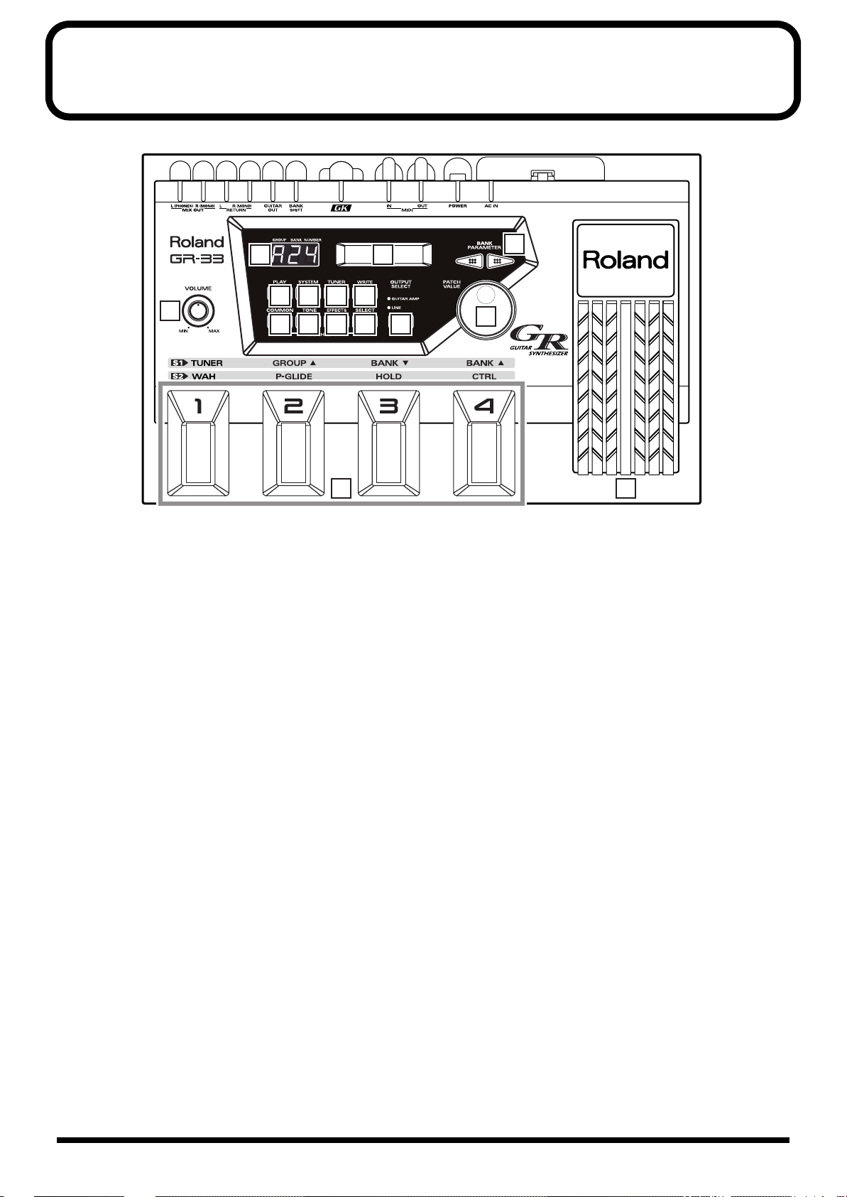
Panel Descriptions
fig.0-01
13 14
2 3 4 5
1
6 7 8 9
1 VOLUME Knob
The VOLUME knob adjusts the signal volume output
from the MIX OUT jack. The center mark provides an
easy reference setting when connecting the GR-33 to an
instrument amp or mixer.
* The output level from the GUITAR OUT jack is controlled
separately.
10
11
12
1615
6 COMMON Button
Press this button to access Patch Edit mode’s
COMMON settings—COMMON settings apply to an
entire patch, as opposed to the settings that apply to its
individual tones or effects.
Press this button to enter Patch Edit mode and adjust
settings such as the patch name and patch pedal
functions.
2 PLAY Button
This button selects Play mode.
To play sounds, press this button to enter Play mode.
(The GR-33 is in Play mode at start-up.)
3 SYSTEM Button
This button selects System mode.
Press this button to enter System mode. When you are
in System mode, you can make settings to the GR-33
itself, as opposed to making settings for specific
sounds.
4 TUNER Button
This button selects Tuner mode.
When you press this button, the Tuner function will be
turned on, and you can tune your instrument.
5 WRITE Button
Use this button to write a patch (Patch Write).
This button also confirms the Factory Reset and Bulk
Dump operations.
7 TONE Button
Press this button to access Patch Edit mode’s TONE
settings—TONE settings shape the sound of the
individual tones that make up a patch.
8 EFFECTS Button
Press this button to access Patch Edit mode’s EFFECTS
settings—these settings allow you to adjust the patch’s
reverb, chorus, and multi-effect.
9 STRING SELECT Button
When selecting and activating the tones to be played in
a patch (LAYER), and when setting transposition
(TRANSPOSE) and other individual-string settings, use
this knob to select the string you wish to set up.
10 OUTPUT SELECT Button
This button selects the output device connected to MIX
OUT jacks.
10
Page 11
11 BANK/PARAMETER Button
Press these buttons in Play mode to switch patch banks.
In System mode and Patch Edit mode, these buttons
select the parameter to be adjusted.
12 PATCH/VALUE Dial
In Play mode, turn this dial to scroll through the
different patches or tones in order.
In System mode and Patch Edit mode, use this knob to
adjust parameter values.
13 Three-digit Display
In Play mode, the three-digit display shows the
currently selected patch’s number.
In System mode, Patch Edit mode, and Pedal Effect
mode, this display shows “SYS,” “Edt,” or “PdL,”
respectively, to indicate the current mode. For
parameters that can be set independently for each
string, the display indicates the currently selected
string’s number.
Panel Descriptions
14 Display
In Play mode, the main display shows the currently
selected patch’s name and the current Harmonist/
Arpeggiator status.
In other modes, the display shows the value and status
of the currently selected item, or “parameter.” Various
messages also appear on this display.
15 Foot Pedal
These are four foot-operated switches. In Play mode,
together with the GK-2A’s “S1,” they primarily switch
patches. After pressing the GK-2A’s “S2” to go into
Pedal Effect mode, you can step on a switch to activate
performance effects such as wah, pitch glide, and hold.
16 Expression Pedal
Use this pedal to control a variety of things, including
the volume, tone and pitch of the current synth sound,
and the arpeggiator tempo.
●
When you operate the expression pedal, please be
careful not to get your fingers pinched between
the movable part and the panel.
In households with small children, an adult
should provide supervision until the child is
capable of following all the rules essential for the
safe operation of the unit.
11
Page 12
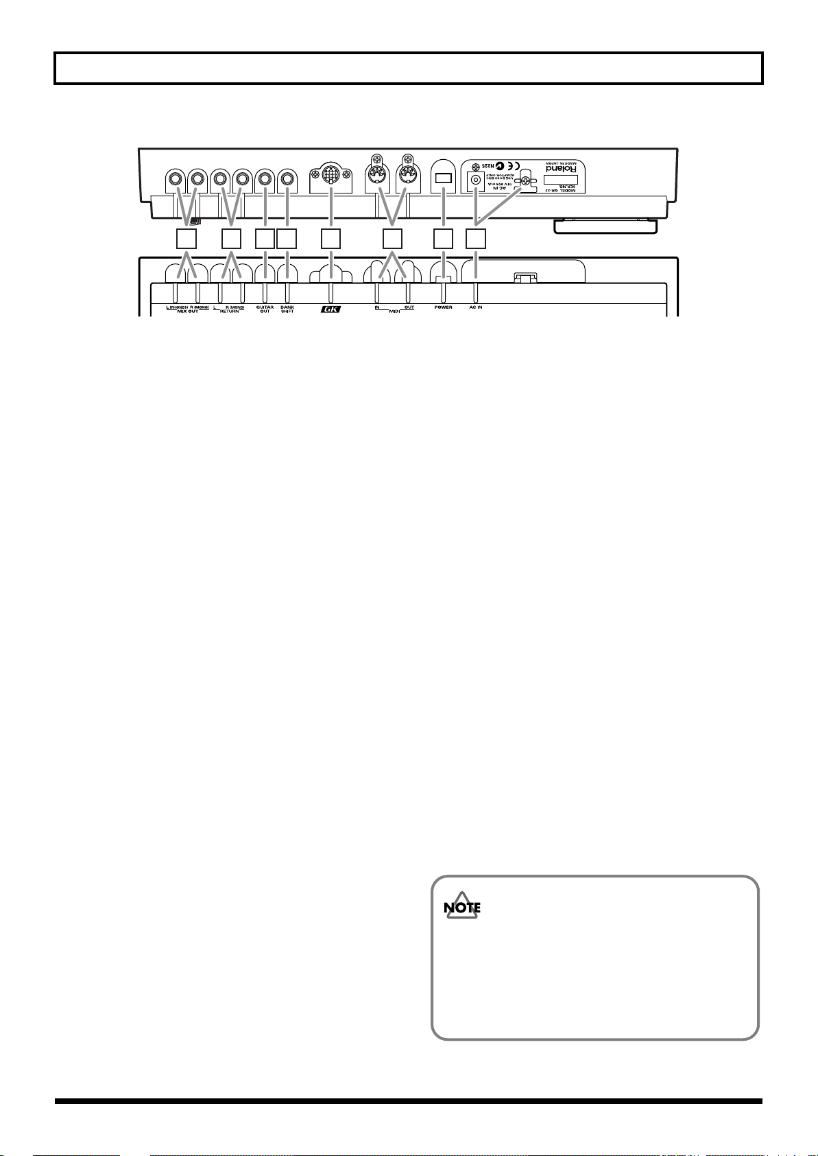
Panel Descriptions
fig.0-02
17 18 19 20 21 22 23 24
MIX OUT Jacks L(PHONES)/R(MONO)
17
The output of the synthesizer is sent out, or “output,”
from here. Ordinarily, two cables are plugged into the
L and R jacks, and the signal is then sent to a stereo
amplifier.
You can use the L (PHONES) jack as a headphone jack
for stereo headphones that have a standard 1/4” stereo
plug—leave the R (MONO) jack unplugged.
You cannot simultaneously use the R (MONO) jack as a
mono output while using the L (PHONES) jack as a
headphone jack.
When there is nothing connected to the GUITAR OUT
jack, the sound of the guitar itself is also mixed into
these outputs.
* In order to fully experience the quality of the factory-installed
patches, we recommend using a stereo amplifier or stereo
headphones. When connecting the GR-33 to a mono amp, use
only the R (MONO) jack.
21 GK IN Connector
Use this special 13-pin branch cable, included with the
GR-33, to connect the GK-2A divided pickup (sold
separately).
* For connection to a guitar designed for use with a synthesizer,
consult the guitar’s manufacturer or your dealer.
22 MIDI Connectors (MIDI IN/OUT)
Plug MIDI cables into these jacks to connect the GR-33
to an external MIDI device. Do this when you want the
GR-33 to control sounds in an external MIDI sound
generator module, or to load tone data stored on an
external MIDI storage device.
23 Power Switch
This is the switch that turns power to the GR-33 on and
off.
18 GUITAR RETURN Jack L/R(MONO)
When using the GUITAR OUT jack (see below) as an
external effect send, use this jack to return the signal.
The synthesizer sound and the guitar sound with
effects are output together from the MIX OUT jacks.
19 GUITAR OUT Jack
Use this jack when you want the guitar sound to be
output from the GR-33 separately from the synth
sound. Connect the jack to your guitar amp or guitar
effects devices.
20 BANK SHIFT Jack
Use this jack for connecting a patch bank expansion
foot switch to the GR-33.
You can connect two Boss FS-5U foot switches using a
PCS-31 cable (each sold separately). Expansion foot
switches control different functions in all modes except
Play mode.
24 AC Adapter Jack/Cord Hook
Connect the AC adapter included with the GR-33 to
this jack. Hang the adapter cord on the cord hook to
help prevent the accidental pulling out of the cord from
the jack while you are playing.
* Use ONLY the AC adapter included with this guitar
synthesizer.
The explanations in this manual include illustrations that
depict what should typically be shown by the display.
Note, however, that your unit may incorporate a newer,
enhanced version of the system (e.g., includes newer
sounds), so what you actually see in the display may not
always match what appears in the manual.
12
Page 13
Chapter 1 Producing Sounds
What You Need
The following items are necessary for getting sounds from your GR-33:
●
GR-33 base module, with included accessories (AC adapter, 13-pin cable)
●
Amplifier, speakers, and cables—a completely stereophonic system is preferable—or stereo headphones
● GK-2A divided pickup
● Metal-stringed guitar with GK-2A properly installed
In addition to the above items, you should also have the following items on hand if needed:
● Guitar amplifier, guitar effects (for adding to guitar sounds)
● External bank shift switches (Boss FS-5U, optional) — to use two foot switches, a branch cable (stereo x 1 → mono x 2, 1/4”
phone plugs) is required (p. 23)
● MIDI foot controller (FC-200 or similar unit, optional) (p. 24)
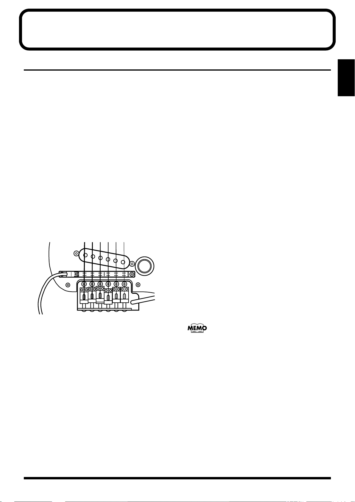
Installing the GK-2A
Before you can use your guitar with the GR-33, the GK-2A
must first be properly installed on the guitar.
Following the procedure outlined in the GK-2A owner’s
manual, attach the GK-2A’s pickup as shown in the picture.
fig.1-20
Guitars That Cannot Be Used with the
GK-2A
While the compact design of the GK-2A allows its
installation on many different guitars, please note the
following types of guitars on which it cannot be used:
a. 12-string, pedal steel, and other specially strung guitars;
nylon-strung, gut-strung, and similar guitars; bass
guitars. (The GK-2A will not operate successfully if
installed on such instruments.)
b. Guitars which, due to their physical design, lack the
space for proper mounting of the GK-2A.
Regarding situation “b.” above: You may be able to install
the GK-2A after a minor modification of the guitar. Please
consult the dealer where you purchased your GK-2A.
Chap.
1
* Be sure the Divided Pickup is correctly oriented: the cord from
the Pickup should emerge from under the sixth string.
* Assembly instructions for use of the GK-2A with the other
device may appear in the GK-2A owner’s manual. Installation
for use with the GR-33 follows the same logic.
To confirm the quality of the GK-2A installation, please take
special note of the following points:
● Make sure that the space between each string and its
pickup is exactly 1 mm when you press the top fret. (Do
not allow the string to get too close to the pickup.)
● Do not allow the space between the guitar bridge and the
GK-2A pickups to exceed 20 mm.
● Make sure that the placement of each of the pickups’ six
yokes (pole pieces) in relation to each string is correct.
For more detailed instructions, please refer to the GK-2A
owner’s manual.
Some guitar manufacturers are currently shipping guitars
that can be connected directly to the GR series with a 13-pin
cable, without the use of a GK-2A. For more information,
please ask your dealer or these guitar manufacturers.
* Take care when dealing with guitars that have more than 25
frets, or unusually high tunings, as the response around the
upper frets may not be sufficient for taking full advantage of
the GR-33.
13
Page 14
Chapter 1 Producing Sounds
Making Connections
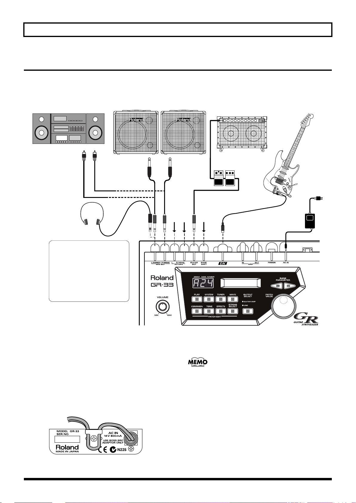
After setting up the guitar part of your system, connect your other equipment following the examples shown in the connection
diagram below.
fig.1-01
Stereo set,
radio-cassette player, etc.
To AUX, LINE IN
L
R
Synthesizer amp
(keyboard amplifier, PA system, etc.)
LR
Guitar with GK-2A/
other GR-compatible guitar
Guitar amp/
guitar effects processors
D
O
W
N
/S
S
Y
1
N
T
H
U
V
P
O
/S
L
2
Stereo
headphones
The (L) MIX OUT jacks can also
be used as dual stereo headphone
jacks.
Also be aware that you cannot
simultaneously use one jack as a
LINE OUT while using the other
as a headphone jack — that is,
you can't use a monaural plug
and a stereo plug at the same
time.
* To prevent malfunction and/or damage to speakers or other
devices, always turn down the volume and turn off the power
on all devices before making any connections.
* Raise the volume of the amplifier only after you turn on the
power to all connected devices.
* To prevent the inadvertent disruption of power to your unit—
as a result of the plug being pulled out accidentally—and to
avoid applying undue stress to the AC adapter jack, anchor the
power cord using the cord hook as shown in the illustration.
fig.1-02
See p. 23See p. 15
AC adaptor
(BRC series)
* If you are outputting a mono signal from the GR-33, connect
the cable to the R (MONO) jack of the MIX OUT jacks.
<Stereo Out>
To get the optimal performance from the GR-33, and to fully
experience the quality of its patches, connect your setup to a
stereo (two-channel) amplifier/speaker system, or to stereo
headphones. Stereo equipment is the best way to hear the
fullness of the GR-33’s sound.
14
Page 15
Chapter 1 Producing Sounds
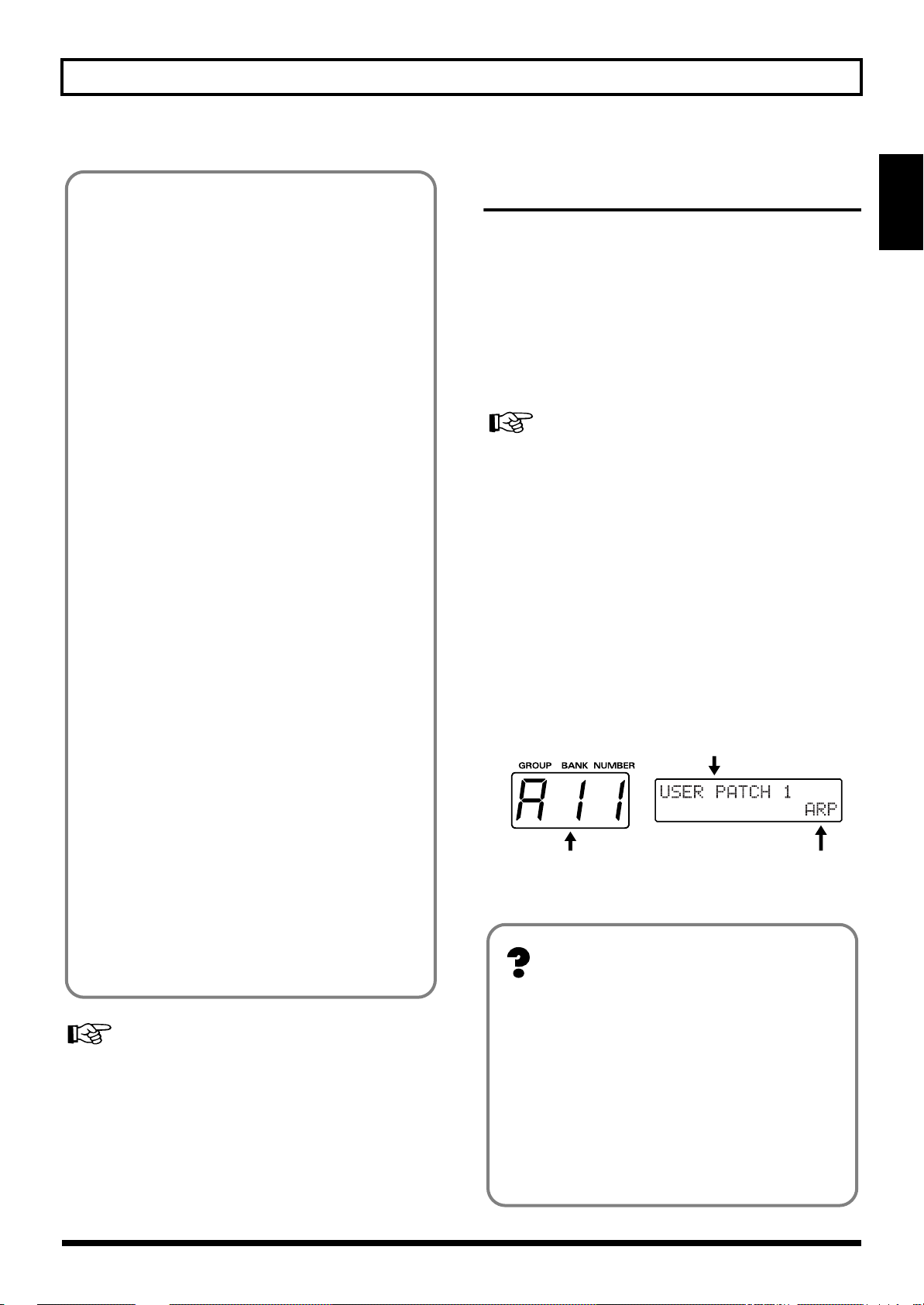
Currently Selected Patch
(A11)
Patch Name
Harmonist (HAR)
or
Arpeggiator (ARP)
<Output>
Outputting the guitar sound and synth sound separately
You can connect a general-purpose shielded cable to the
GUITAR OUT jack to add external guitar effects or to
send your guitar sound to your guitar amplifier. With
this arrangement, you can control the sound of the guitar
exactly the same way you would if the guitar were not
connected to the GR-33. The synthesizer sound —
without the guitar sound mixed in—will be output from
the MIX OUT jacks.
Outputting the guitar sound and synth sound together
Connect cables only to the MIX OUT jacks—do not
connect a cable to the GUITAR OUT jack. The sound of
the guitar itself will be output along with the synth
sound from the MIX OUT jacks. This way, both guitar
and synthesizer sounds can be played through a single
stereo (or mono, if necessary) amp.
Applying an external effect only to the guitar sound
and outputting it along with the synth sound
Make the following connections.
Necessary Steps—From Powering Up to Performance
* Once your connections have been completed (p. 14), turn on
power to your various devices in the order specified. By
turning on the devices in the wrong order, you risk causing
malfunction and/or damage to speakers and other devices.
After you have finished checking your connections, turn the
GR-33’s VOLUME knob all the way counterclockwise—thus
turning its volume all the way down—and press the power
switch on the rear panel to turn on the GR-33.
(Pressing the switch again turns the power off.)
If you wish, use the procedure described in “Reset to Default
Factory Settings (Factory Reset)” (p. 16) to return the GR-33’s
settings to their original values before beginning.
* This unit is equipped with a protection circuit. A brief interval
(a few seconds) after power up is required before the unit will
operate normally.
About Play Mode
Chap.
1
GR-33 GUITAR OUT Jack
↓
External Effect Input
External Effect Output
↓
GR-33 GUITAR RETURN Jack
The synthesizer sound and the guitar sound with effects
are output together from the MIX OUT jacks.
Listening through headphones
Make sure nothing is plugged into the L (MONO) MIX
OUT jack, and connect a set of stereo headphones to the
R (PHONES) jack.
* You cannot simultaneously use the R (MONO) jack as a
LINE OUT while using the L (PHONES) jack as a
headphone jack—that is, you can’t use a monaural plug
and a stereo plug at the same time.
For settings appropriate to your output device, refer to
“Specifying the output device (OUTPUT SELECT)” (p. 19).
After turning on the GR-33, confirm that “A11” appears in
the three-digit display window. This is the number of the
currently selected patch. Each patch contains a pair of tones
that can you can switch with a pedal, etc. during
performance. (→ For details, see p. 21.)
fig.1-03
<About Play Mode>
When a patch number—such as the “A11” that appears
right after the power is turned on—is shown in the
display, you are in Play mode. You will typically be in
Play mode as you perform. Play mode is the basic state
of the GR-33.
Until you are familiar with how everything in the GR-33
works, remember this: You can always return to Play
mode by turning the power off and then on again.
(For more about how the dials and buttons work in Play
mode, please see p. 30.)
15
Page 16
Chapter 1 Producing Sounds
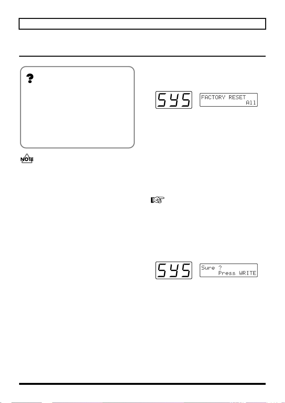
Reset to Default Factory Settings (Factory Reset)
■ Performing a Factory Reset
1. Press [SYSTEM] to enter System mode.
<About Factory Reset>
The procedure for restoring the GR-33’s internal settings
to the state they were in when the unit left the factory is
called a “Factory Reset.”
At the time of purchase, the GR-33’s user patches (A11 to
D84) are the same as preset patches E11 to H84. These
patches, as well as the GR-33’s system settings—
including pickup sensitivity and the MIDI channels used
for sending and receiving MIDI data—can be returned to
their original factory-fresh state.
The Factory Reset operation undoes any settings you have
changed and discards any edits you have made to its
patches. If you have settings or patches you wish to preserve,
use the Bulk Dump operation (p. 37) to save them to an
external MIDI device, such as a sequencer, before performing
the Factory Reset operation.
2. Press [PARAMETER] to select “FACTORY RESET.”
fig.1-04
3. Turn [VALUE] to select the parameter—or group of
parameters—you wish to reset.
• All:
Restores all settings to their original state.
• System:
The System settings will be restored to their factory
settings.
• User Patch:
Patch settings will be restored to their original state.
• PC Number:
Program Change numbers are re-assigned according to
the current order of the patches.
For more detailed information about the “PC Number,” refer
to “Re-assigning Program Change Numbers in the Order of
Patches” (p. 97).
4. When you have selected the desired parameters, press
[WRITE].
The message “Sure ?” appears, asking you to confirm
that you want to go ahead and perform the Factory Reset
operation.
fig.1-05
5. To execute the operation, press [WRITE] again.
“Now Writing...” appears in the display. In a moment,
the GR-33 automatically returns to Play mode,
completing the factory Reset.
To cancel the operation, press [PLAY].
* This means that the processing of data is in progress. Once
you press [WRITE], be sure not to turn off the power until to
return to Play mode.
16
Page 17
Chapter 1 Producing Sounds
w
Overall Settings for the GR-33 (SYSTEM)
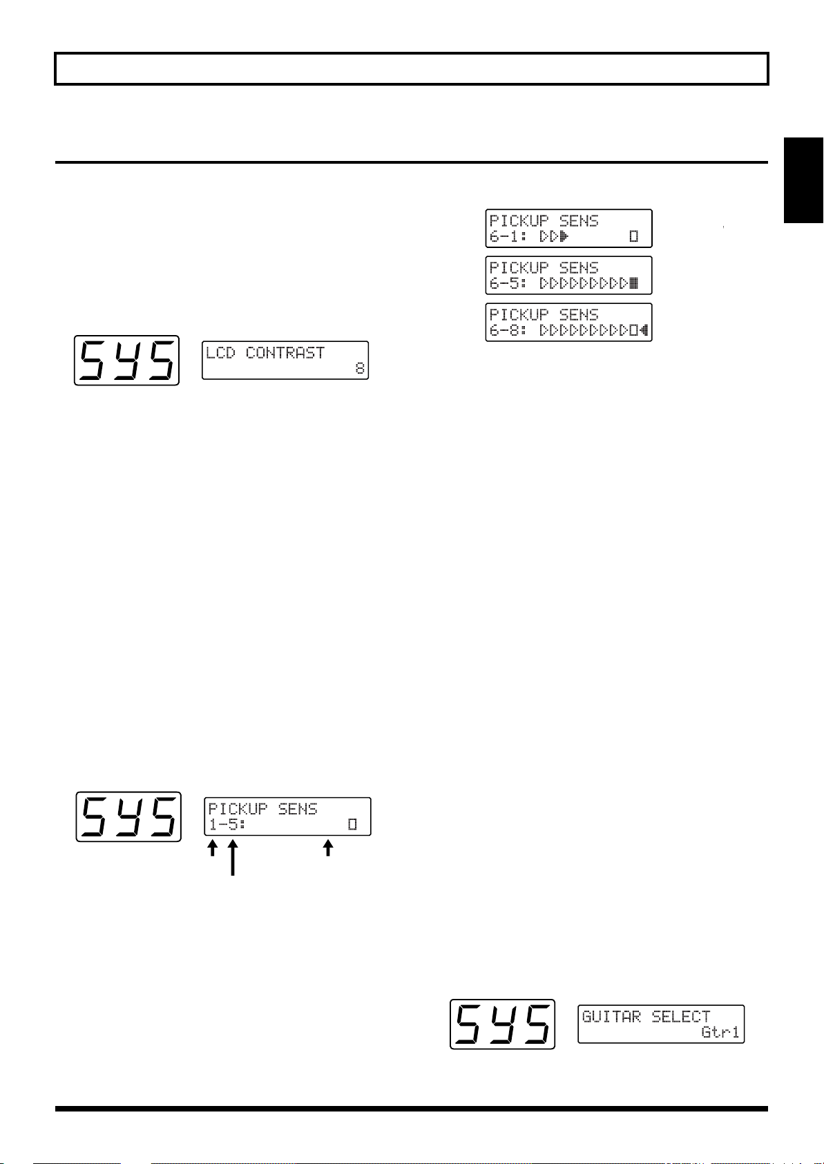
Adjusting the Brightness of the Display (LCD Contrast)
■ Adjusting the Brightness of the Display
1. Press [SYSTEM] to enter System mode.
2. Press [PARAMETER] to select “LCD CONTRAST.”
fig.1-06
3. Turn [VALUE] to adjust the contrast.
4. When you have finished adjusting the display, press
[PLAY] to return to Play mode.
Setting Input Sensitivity (PICKUP SENS)
With the power turned on, adjust the input sensitivity of
each string according to how the GK-2A is mounted and to
match your own picking strength. Since these settings are
stored automatically—and will not be lost even if the power
is turned off—it is not necessary to reset the sensitivity each
time you play.
■ Procedure for Setting Input Sensitivity
1. Press [SYSTEM] to enter System mode.
2. Press [PARAMETER] to select “PICKUP SENS.”
Sensitivity-setting is activated, and the following
appears in the display window:
fig.1-07
fig.1-21
If the indicator furthest to the left is lit, the level is set too
high, so turn [VALUE] to lower the sensitivity.
* If the sensitivity is set too high, there may be dropouts in the
sound, or the response to dynamic changes in your playing
may be reduced. Setting sensitivity too low may also result in
problems, so make this adjustment carefully.
5. Adjust Strings 5 to 1 using the same technique.
6. When you have finished, press [PLAY] to return to Play
mode.
In any of the following situations, please be
sure to readjust the sensitivity settings!
• When using a guitar for which you have not yet made
sensitivity adjustments
• After performing a Factory Reset (p. 16)
• When you change the mounting of the GK-2A to
accommodate a change in the guitar, such as when string
height has been readjusted
• When you replace a string with one of a different gauge
In some rare cases, the sensitivity meter may show too high a
reading even with sensitivity at its lowest setting. If this does
occur, widen the space slightly between the GK-2A’s
separate pickups and the strings.
Chap.
1
Sensitivity: lo
Sensitivity: hi
String Number
Input Sensitivity
3. When String 6 of the guitar is played, the string
number in the display automatically switches to “6.”
The level meter shown in the display will light from the
left, showing how strongly the string is played. The
current input-sensitivity setting for the string will also be
displayed next to the string number.
4. Use [VALUE] to adjust the sensitivity so that the square
indicator lights when you play most strongly in actual
performance.
Level Meter
Using Multiple Guitars (GUITAR SELECT)
You can store four separate string-sensitivity setups that can
be called up to match any of four guitars you are currently
using.
■ Calling Up the Different Sensitivity Settings
1. Press [SYSTEM] to enter System mode.
2. Press [PARAMETER] to select “GUITAR SELECT.”
fig.1-08
17
Page 18
Chapter 1 Producing Sounds
String Numbers 1 to 6
Pitch name
(“D#” – The marking in the third place denotes sharp)
3. Turn [VALUE] to select Gtr1–Gtr4.
The setting you select will be loaded.
* With the factory settings, this is set to “Gtr1.”
If you wish to create a new input-sensitivity setup, press
[PARAMETER] to select “PICKUP SENS,” and then
adjust the sensitivity settings for the current guitar’s six
strings.
4. After setting each string’s sensitivity, press [PLAY] to
return to Play mode.
Create four different input-sensitivity setups for Gtr1–
Gtr4 to store the sensitivity settings for four different
guitars.
* The last-selected sensitivity setup is the one currently in effect.
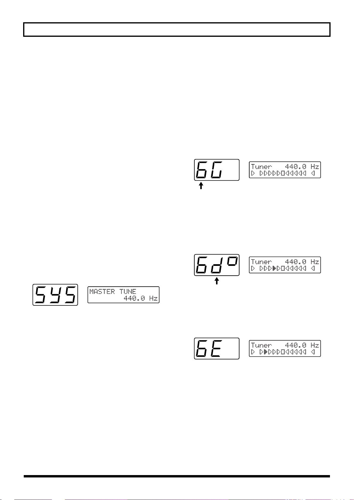
Matching Pitches of Other Instruments
The master tuning (basic pitch) set at the factory for the GR33’s sounds and internal tuner is A = 440.0 Hz.
If you need to match the GR-33’s tuning to the tuning of
another instrument—or if you want to change the master
tuning for any other reason—perform the following steps.
■ Changing the Master Tune Setting
Adjusting the Guitar Tuning (Tuner Function)
To accurately set a guitar’s pitch, use the GR-33’s built-in
tuner to tune the guitar. This tuner works exactly the same
way other tuners on the market do.
■ Tuning the Guitar
1. While pressing [S1] on the GK-2A, step on the first foot
pedal—[1] (TUNER) —or press [TUNER].
The Tuner function is called up, and the following
appears in the display.
fig.1-09
2. Play String 6 on the guitar.
The string number automatically switches to “6.”
The note to which String 6 is currently tuned—notes are
tuned by semitones—is shown in the second position on
the display. (“D#” in the figure shown below.)
fig.1-10
1. Press [SYSTEM] to enter System mode.
2. Press [PARAMETER] to select “MASTER TUNE.”
fig.1-13
3. Turn [VALUE] to select the desired pitch. The pitch can
be changed to any frequency from 427.4 to 452.6 Hz.
4. Press [PLAY] to return to Play mode.
* The pitch of the synthesizer sound does not change when you
change the GR-33’s Master Tune setting—the synth sound
continues to follow the tuning of the guitar. Therefore, after
adjusting the master tuning, you should use the Tuner
function to re-tune your guitar to the new basic pitch, and the
pitch of the synth sounds will play in the new tuning.
3. Turn the string’s tuning peg while playing String 6
until the screen shows the name of the note to which
you want to tune the string.
fig.1-11
4. Make fine adjustments to the string’s tuning peg until
the mark illuminated in the display moves to the center
position and both side.
When the center indicator lights, String 6 is tuned
precisely to “E.”
18
Page 19
Chapter 1 Producing Sounds
fig.1-12
too high
Just Tuned
too low
5. Tune each of the other strings, 5 to 1, to A, D, G, B, and
E, respectively.
6. When you are finished tuning, press any foot pedal,
[S1] or [S2] on the GK-2A, or [PLAY], to return to Play
mode.
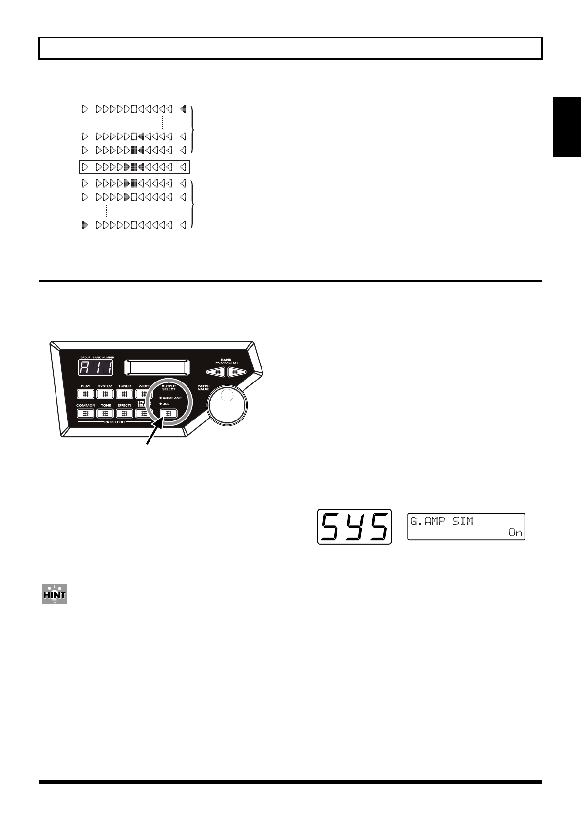
Selecting the output device (OUTPUT SELECT)
In order for the GR-33 to produce the correct output levels,
you must select the type of device to which its outputs are
connected (MIX OUT).
fig.1-14
Turning off the guitar amp simulator (G.AMP SIM)
The GR-33 has a built-in guitar amp simulator (G.AMP SIM).
If OUTPUT SELECT is set to “LINE,” the guitar amp
simulator will be applied only to the guitar sound itself. This
allows you to create the illusion of the original guitar sound
being played through a guitar amp, even when it is being fed
directly into another device.
If you are not using the GR-33’s internal guitar amp
simulator—if you are using an external amp simulator effect
device, for example—set the GR-33 as follows.
Chap.
1
1. Press [OUTPUT SELECT] and select the appropriate
setting.
The currently selected setting will light.
• GUITAR AMP:
Select this when using a dedicated guitar amp.
• LINE:
Select this when using a keyboard amp, general-purpose
instrument amp, mixer, MTR, or headphones.
The GR-33’s sound generator is a PCM synthesizer that can
reproduce a wide range of timbres. To optimally capture its
rich synthesizer sounds, use a keyboard amp, other general
instrument amplifier, PA system, or other such equipment
instead of a guitar amplifier if possible.
* Changing the OUTPUT SELECT setting will not affect the
settings that are stored in each patch.
■ Turning the Amp Simulator Off
1. Press [SYSTEM] to enter System mode.
2. Press [PARAMETER] to select “G.AMP SIM”
fig.1-15
3. Turn [VALUE] to select “Off.”
• Off:
The amp simulator will not be used.
• On:
The amp simulator will be used when OUTPUT SELECT
is set to “LINE.”
4. Press [PLAY] to return to Play mode.
* When you once again wish to use the amp simulator, select
“On” in Step 3.
19
Page 20
Chapter 1 Producing Sounds
Playing the Internal Synth Sounds with the Guitar
After checking the connections to the amplifier you are using, completing the sensitivity setup and tuning your guitar, try playing
some sounds.
■ How to Play the GR-33’s Sounds with the
Guitar
1. Make sure that the display indicates Play mode (p. 15).
2. Set the GK-2A’s selector switch to “SYNTH.”
3. Turn SYNTH VOL on the GK-2A counterclockwise to
raise the volume to a suitable level.
4. Set the VOLUME knob on the GR-33 to its center
position.
5. When you press Pedal 3, the number in the display
changes to “A13,” and the corresponding patch (sound)
is selected.
You are now ready to play. Play your guitar while gradually
turning up the volume on your amplifier, and you will hear
the selected patch—patch A13—from the GR-33’s internal
sound generator.
❍ To Hear the Normal Guitar Sound...
Set the GK-2A’s selector switch to “MIX.” If you then
switch to “GUITAR,” the synthesizer sound generator
will be muted, and only the sound of the guitar will
remain.
To Change the Volume of the Synth Sound Generator...
❍
Adjust the volume using either the SYNTH VOL knob
on the GK-2A or the GR-33’s VOLUME knob.
Turning the GR-33’s VOLUME knob changes the overall
volume output from the MIX OUT jacks. Thus, when the
guitar sound is included in the MIX OUT signal, both guitar
and synthesizer sound levels are changed. (The guitar sound
output from the GUITAR OUT jack is not affected. The guitar
volume is also unchanged when you use the GK-2A’s
SYNTH VOL knob.)
What To Do if There is No Sound When the Guitar is Played
First, check the following:
• Check to see that amplifier and other equipment volume
levels are correct, and confirm that all the equipment is
properly connected (p. 14).
• Make sure the volume on both the GR-33 and the GK-2A
are up. Also, make sure that the guitar/synth switch is
not set to GUITAR.
❍ When the Sound of a Specified Patch Fails to Play on
All the Strings (or on a Particular String)
• Try pressing the expression pedal (p. 11) as far down as
it will go.
• When using a monaural connection to your amp, be sure
to connect your cable to the R (MONO) jack of the GR-33
MIX OUT jacks.
• Confirm that the synth sounds have not been muted for
any strings in the TONE “LAYER” parameter in Patch
Edit mode (p. 51).
If the volume levels of the strings vary widely, please recheck
your input sensitivity (PICKUP SENS) settings (p. 17).
20
Page 21
Chapter 2 Selecting and Playing Sounds (Patches)
What Is a Patch?
“Patch” is the term for the GR-33’s tones that can be called up
at any time with a foot switch or other device. There are 256
patches stored in the GR-33. As an example, the “A11” that
appears in the display when the power is switched on
indicates that patch number A11 has been called up, and that
the unit is ready to be played.
This unit’s basic unit of sound is the “tone.” Tones consist of
sound waveforms, such as “GR Piano,” “Pipe Organ,” and
“Nylon Gtr mp” A total of 384 such tones are provided
onboard. (How to choose tones → p. 49; list of tones → p.
122)
In any patch, up to two selected tones are combined, and
then various settings and adjustments, such as brightness,
attack, difference between synthesizer and guitar pitch, and
the like are made. The user has full freedom to make these
settings and adjustments so that the patch may best suit the
song to be played.
Another result of changing these settings is that you can
write and store 128 patches (in the first half of the patch
bank). (For more detailed information about patches, please
refer to p. 35.)
Patch numbers are indicated by a three-digit code: “a letter of
the alphabet A–H (Group),” followed by “a numeral 1 to 8
(Bank),” and then “a numeral 1 to 4 (number on the pedal).”
(Example: A83, d24, F61, etc.)
fig.2-01
Rewritable Patches (User Patches)
Patches in Groups A through d
(A11 to A84, b11 to b84, C11 to C84, and d11 to d84)
Here you can create patches to fit a song, or for other
purposes, and then store those patches in memory.
(When you purchased your GR-33, the patches stored in
these groups were the same as the following preset patches.
If you want to reset the GR-33 patches to the original
conditions, please carry out the Factory Reset operation
explained on p. 16.)
Read-only Patches (Preset Patches)
Patches in Groups E through H
(E11 to E84, F11 to F84, G11 to G84, and H11 to H84)
This is a collection of 128 preset patches, which have already
been completely prepared by Roland. These patches are
read-only, so although they can be changed, they cannot be
written over with another patch. However, this also means
no worries that they might be erased accidentally.
Preset patches are called up and used in the manner as user
patches. Furthermore, they are convenient as references and
basic material for the user wishing to create original patches.
Chap.
2
Numerals 1 to 4 (Pedal Numbers)
Numerals 1 to 8 (Banks)
Letters A, b, C, d, E, F, G, H (Groups)
Consecutive numerals 001 to 256 can also be substituted (p. 24).
Selecting a Patch
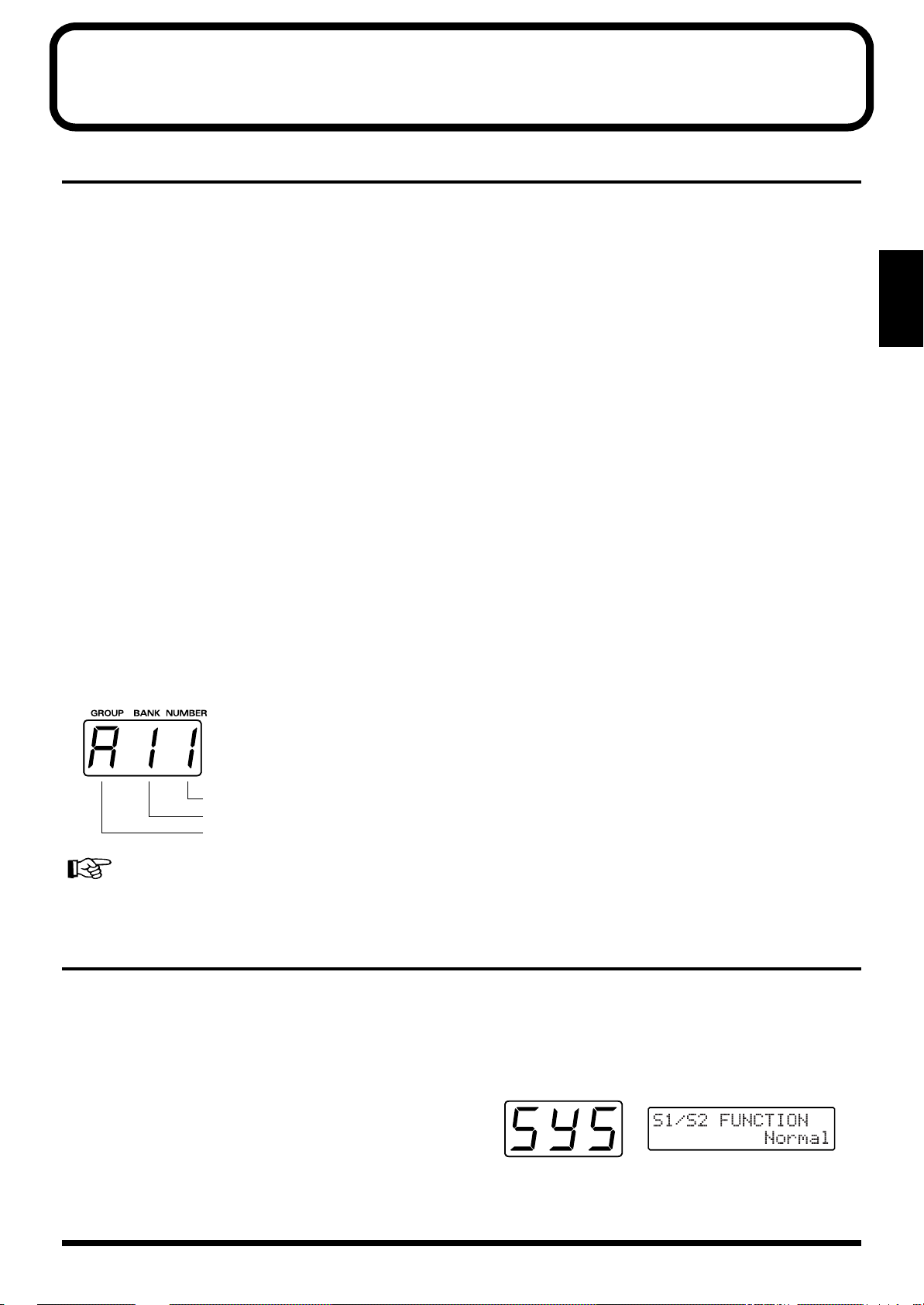
Using the Guitar (GK-2A) to Select Patches
Sometimes (such as when you want to listen to all of the
patches one after the order) you will want to select patches
using only the guitar (GK-2A). In such cases, follow the steps
below. (It is unnecessary to touch any pedal or anything else
on the base module.)
■ How to Select a Patch Using the Guitar
1. Press [SYSTEM] to enter System mode.
2. Press [PARAMETER] to select “S1/S2 FUNCTION.”
fig.2-02
21
Page 22
Chapter 2 Selecting and Playing Sounds (Patches)
3. Use [VALUE] to select “Patch Select.”
• Patch Select:
You can continuously switch patches with [S1] and [S2]
on the GK-2A.
• Normal:
Normal status. You cannot switch patches on the GK-2A.
4. Press [PLAY] to return to Play mode.
5. Pressing the GK-2A [UP/S2] once brings you to the next
higher patch; by holding the switch down, you can
switch continuously. Furthermore, when the other
button (here the [DOWN/S1] button) is then also
pressed, the switching occurs even faster. Pressing the
[S1] and [S2] buttons in the reverse fashion will
similarly return you to previous patches.
fig.2-03
S1
(Patch Number Down)
Using the Base Module to Select Patches
Selecting Patches Using the Pedal
You can select patches using the pedal only when “S1/S2
FUNCTION” is set to “Normal.”
For the “S1/S2 FUNCTION” settings, refer to p. 21.
❍ To Use the Pedal for Calling Up Patches from the
Same Group or Bank
When playing live or in the studio, by using the pedal on the
base module, you can instantly select one of four patches
from the same group or bank.
1. Make sure that you are in the Play mode.
If you are not in the Play mode, press [PLAY].
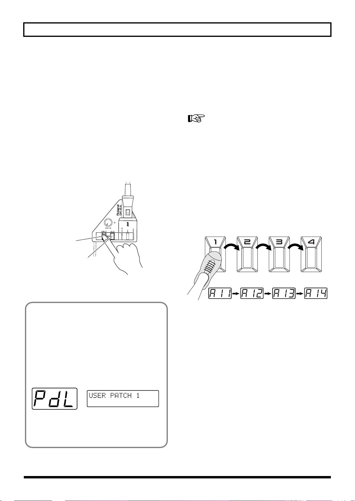
2. When you press pedals 1 to 4, you can instantly select a
patch from the same bank of four patches in a group,
with the number at the right in the display changing to
show the number of the pedal currently pressed.
fig.2-05
S2
(Patch Number Up)
Now, using the GK-2A buttons to switch patches, try playing
the guitar to listen to the patches in sequence.
<Using the Pedal>
With the GR-33 in the state just described, you can get
various pedal effects (explained later). For example hold,
pitch glide, and the like can be obtained, by stepping on
the base unit’s four pedals. (For details, see p. 28.) To
indicate this status, when “S1/S2 FUNCTION” is
selected in “Patch Select,” the “PdL” display appears
(approximately once every four seconds) in the threedigit display, showing the patches and their
corresponding numbers.
fig.2-04
Additionally, with the unit in this status, an external
bank shift pedal can be used to change patch numbers,
both up and down, just like the [S1] and [S2] buttons on
the GK-2A.
❍ To Use the Pedal for Calling Up Patches from a
Different Group or Bank
Used together with the GK-2A’s [S1] button, you can use the
pedal function to switch patches.
1. Make sure that you are in the Play mode.
If you are not in the Play mode, press [PLAY].
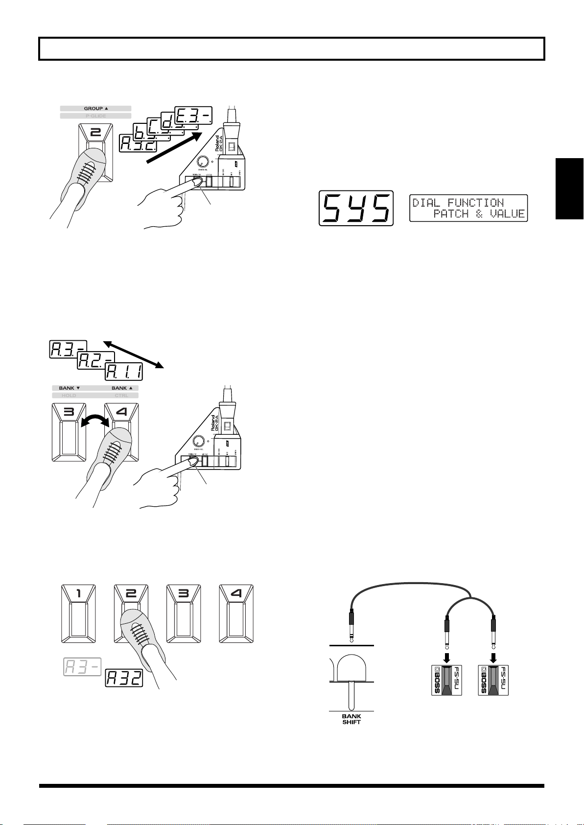
2. While pressing [S1] on the GK-2A, step on [GROUP ▲]
(pedal 2).
Pedal 2 continues switching to the next group only while
[S1] is being held; pressing the pedal allows you to
progress to the next group.
* If you wish to change only the bank without changing the
group, omit step 2, and proceed to step 3.
22
Page 23
Chapter 2 Selecting and Playing Sounds (Patches)
fig.2-06
While holding down S1
3. While pressing [S1] on the GK-2A, step on [BANK ▲]
(pedal 4) or [BANK ▼] (pedal 3).
As long as the [S1] button is held down, pedal 4 works as
a [BANK ▲] (BANK UP), and pedal 3 as a [BANK ▼]
(BANK DOWN). The display starts to flash, and when
you step on pedal 3 or 4, numbers for the bank digit (the
middle number in the display) go down or up.
fig.2-07
Selecting with the Dial
If you wish to use the dial to select patches, you must make
the following setting for the dial.
1. Press [SYSTEM] to enter System mode.
2. Press [PARAMETER] to select “DIAL FUNCTION.”
fig.2-09
3. Use [VALUE] to select “PATCH&VALUE.”
• PATCH&VALUE:
The dial can be used both for selecting the patch number
and for modifying values while editing.
• VALUE Only:
The dial can be used only for modifying values while
editing.
4. After making the setting, press [PLAY] to return to Play
mode.
In Play mode, you can rotate the [VALUE] dial to select
all 256 patches A11–H84.
You can also use [BANK/PARAMETER] to move
forward/backward through the banks.
Chap.
2
While holding down S1
4. After selecting the desired group/bank, release [S1],
then step on the pedals.
When you press a pedal, the patch will be finalized, and
the sound will change.
fig.2-08
Using the Base Module plus an External Foot Switch to Select Patches
By plugging a foot switch into the BANK SHIFT jack on the
rear panel, you can switch banks without pressing [S1] on the
GK-2A.
With one DP-5 (sold separately) to rise through patch bank
numbers, or with two Boss FS-5U foot switches and a branch
cable (sold separately) to move both up and down through
the patch banks, it’s possible to perform this procedure using
only your feet.
fig.2-10
PCS-31
Red
BANK
DOWN
White
BANK
UP
23
Page 24
Chapter 2 Selecting and Playing Sounds (Patches)
* Sometimes when pressing and releasing the foot switch to
switch banks, you may find that while the bank does change,
the patch number may not (light will flash); however, this does
not indicate any malfunction. You can also make the setting
with the FS-5U polarity switch, as shown in the figure below.
fig.2-11
Polarity switch
* If the “S1/S2 FUNCTION” has been set to “Patch Select,” the
action of the foot switch just described changes to switching
patches up and down (p. 21).
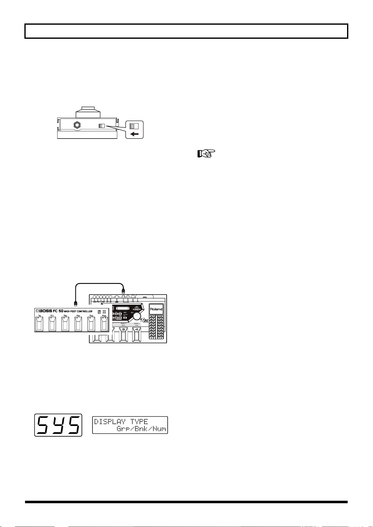
Selecting Patches with an External MIDI Foot Controller
While the base module’s four pedals are being used as
designated pedals (p. 26) for such effects as hold and wah,
you may also wish to switch patches using your foot.
In such cases, you should hook up an external MIDI foot
controller (e.g. FC-200, Boss FC-50, and so on).
Make the settings, using the following procedure.
1. Connect equipment as shown in the figure below.
fig.2-12
MIDI IN
MIDI OUT
MIDI Foot Controller
2. Press [SYSTEM] to enter System mode.
The patch number display corresponds to the display on
the MIDI foot controller, but with numbers 001 to 256
instead of the alphanumeric symbols in patch numbers
used by the GR-33.
4. Use [VALUE] to select “Decimal.”
• Decimal:
Patch numbers will be displayed as a decimal number in
the range of 001–256.
• Grp/Bnk/Num:
Patch numbers will be displayed as a group/bank/
number from A11–H84.
5. Press [PARAMETER] to select “S1/S2 FUNCTION.”
6. Use [VALUE] to select “Patch Select.”
For details, refer to “Selecting a Patch/Using the Guitar (GK2A) to Select Patches.”
7. Press [PLAY] to return to Play mode.
The patch number displayed will be “001,” rather than
“A11.”
8. Set the MIDI send channel of the MIDI foot controller
to match the channel of the GR-33 (p. 86; the factory
setting is channel Mono 11).
9. Use the MIDI foot controller to switch patches
externally, operating the controller according to the
instructions in the owner’s manual.
* The patch number using the numeral-only format that was set
in step 4 is stored in memory even after the power is turned
off. If necessary, return the patch number display to the
Group/bank/number format.
Additionally, user patches (001 to 128, or A11 to D84)
can usually be selected when MIDI program change data
is sent from the MIDI foot controller immediately after
the power is turned on.
* MIDI program change numbers received by the GR-33 have a
fixed one-to-one correspondence with the patches (001 to 128,
or A11 to D84) they represent; this cannot be changed. (On
the other hand, when patches are selected using the GR-33,
you have the freedom to change and save the MIDI program
→
change numbers that send the data to outside equipment.
p.
88)
3. Press [PARAMETER] to select “DISPLAY TYPE.”
fig.2-13
24
Page 25
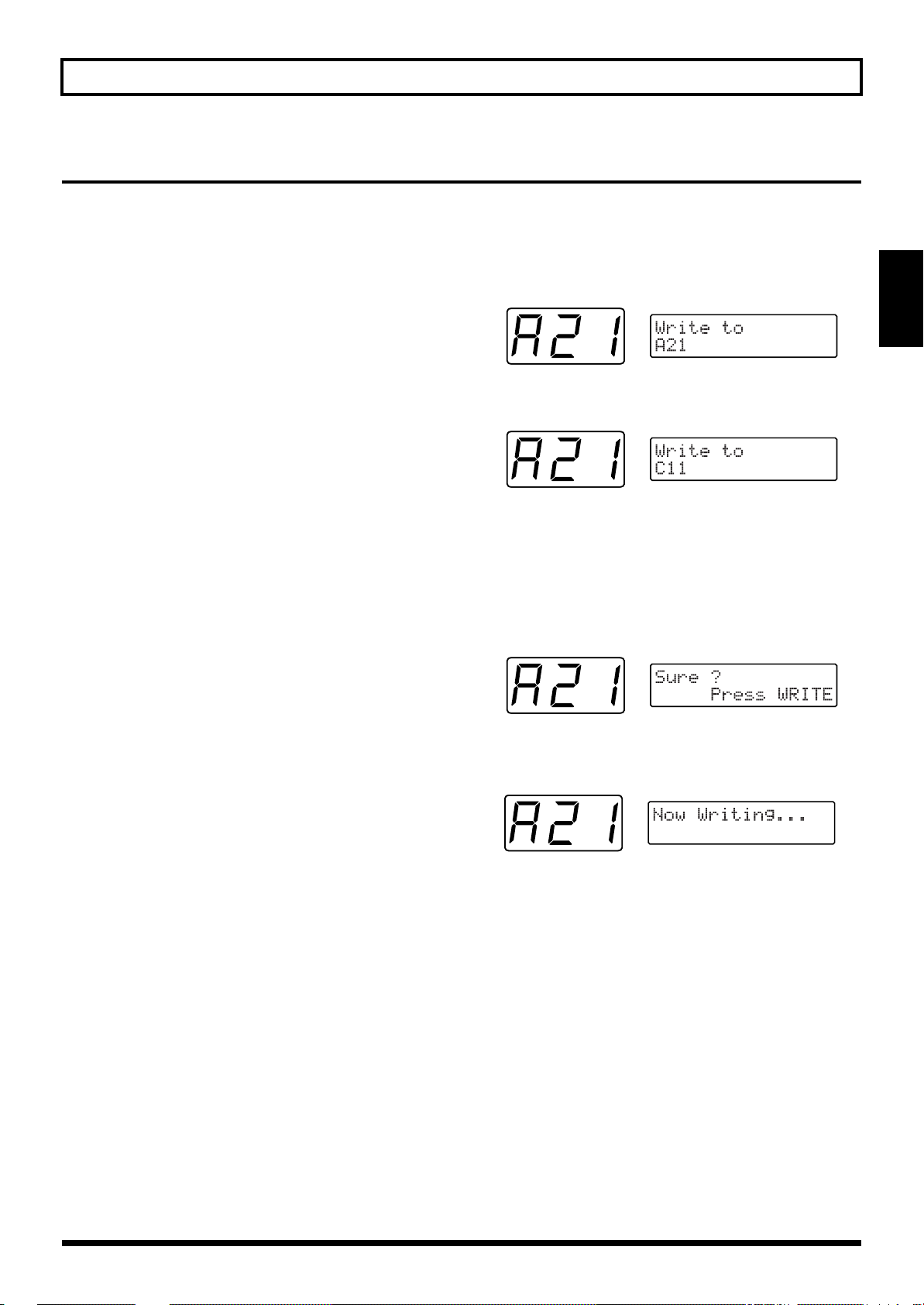
Chapter 2 Selecting and Playing Sounds (Patches)
Changing the Patch Order
When sequencing patches while performing a piece, or while
you are on stage, if the patches are from the same group/
bank (for example A11 to A14), you can switch patches very
smoothly by using the pedals on the base module.
To change the order of the patches, perform the patch write
(p. 36) operation. This designates the patch number (address)
where the patch data from the present selection (or change)
will be written.
Example: To change the contents of A21 and B62
First, to prevent the contents of patch A21 from being lost,
clear a patch number that is not being used. (Since groups A
through d of user patches are the same as groups E through
H of preset patches, you may erase them without worry.)
After that, by writing B62 → A21, then temporary placeholder → B62, the order of A21 and B62 can be swapped.
1. Select the “A21” patch.
2. Press [WRITE].
You enter Write mode, and the screen like the one below
appears.
fig.2-14
3. Use [VALUE] to select the patch you want to write to.
fig.2-15
In this example, we will use “C11” as the writing
destination patch.
4. After you have specified the writing destination patch,
press [WRITE].
The following display will appear, asking you to confirm
the operation.
fig.2-16
Chap.
2
5. After making sure that you want to execute this
operation, press [WRITE] once again.
fig.2-17
“Now Writing...” appears in the display, the unit
automatically returns to the Play mode, completing the
writing procedure.
6. Using steps 1 to 5 above, write B62 → A21 just as you
did A21 → temporary place-holder (C11).
7. Complete the rearrangement by using the same process
to write the temporary place-holder (C11) → B62.
* Since patch groups E through H are read-only, you cannot
rearrange their order or create temporary place-holders with
them. (However, you can copy them for reference or to use
them as starting material when writing new patches.)
25
Page 26
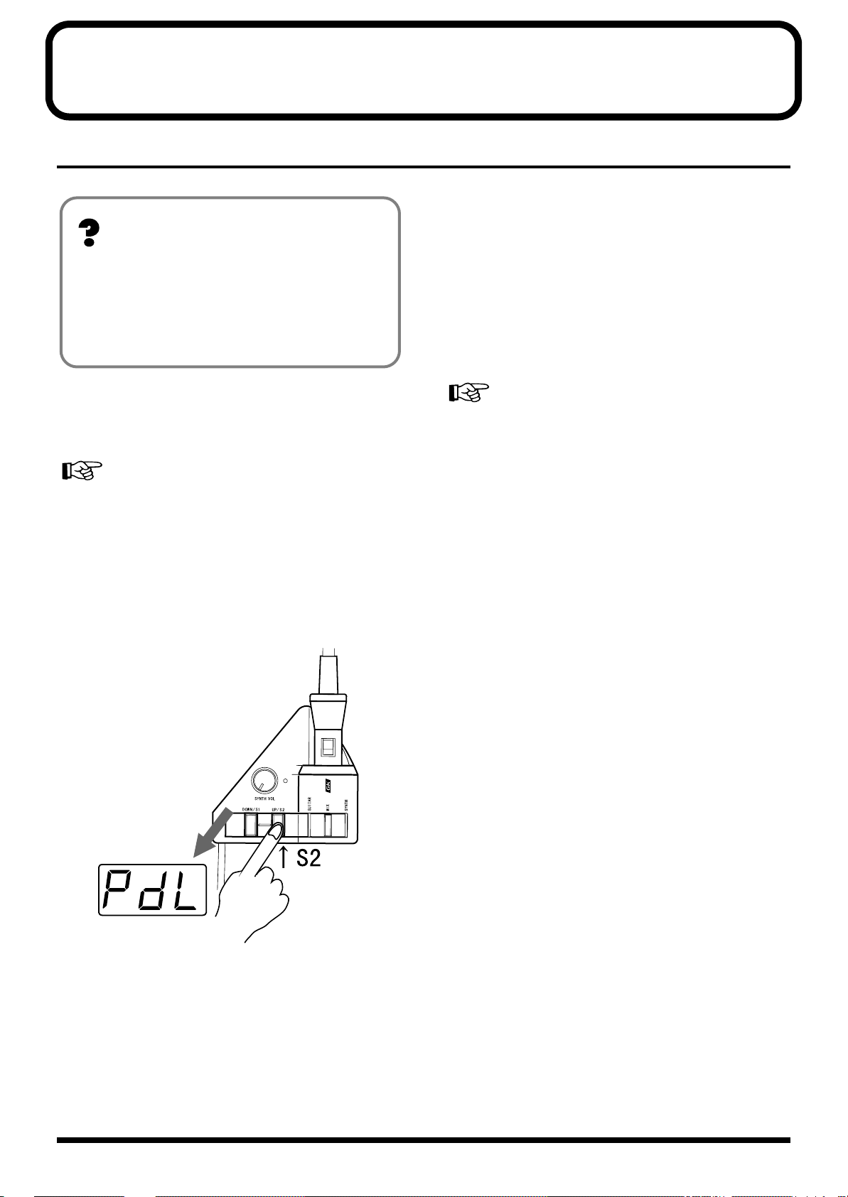
Chapter 3 Controlling Functions and Effects
with the Base Module Pedals
“Pedal Effect Mode”: What It Is, and How to Call It Up
Getting the Same Effect While in Play Mode
About Pedal Effect Mode
By using the four pedals on the GR-33, you can turn on
and off the Arpeggiator (and Harmonist) function, and
get effects such as synth sound hold and wah pedal.
This is called “Pedal Effect mode,” and along with the
Play mode, is often used in performance.
■ How to Switch to Pedal Effect Mode
1. Press [SYSTEM] to enter System mode, and set the “S1/
S2 FUNCTION” to “Normal.”
For more detailed information and instructions for this
procedure, refer to “Selecting a Patch/Using the Guitar (GK2A) to Select Patches” (p. 21).
If you have set “S1/S2 FUNCTION” in System mode to
“Patch Select” in order to use the buttons of the GK-2A for
selecting patches, you can use pedal effects in Play mode.
The four pedals will act as they do in Pedal Effect mode
instead of selecting patches as they normally would in Play
mode. (“PdL” will appear once every four seconds or so in
the 3-digit display, indicating that pedal effects are
available.)
For more detailed information and instructions about this
type of setup, refer to “Selecting a Patch/Using the Guitar
(GK-2A) to Select Patches” (p. 21).
* With the exception of the arpeggio latch hold (p. 76), pressing
more than one pedal at the same time can result in unexpected
behavior, so please exercise due caution.
2. Press [PLAY] to return to Play mode.
3. Press [S2] on the GK-2A once.
As you enter Pedal Effect mode, “PdL” (Pedal) will start
to blink in the GR-33’s three-digit display.
fig.3-01
Press either [S1] or [S2] on the GK-2A to return to Play
mode.
The same pedal can produce different effect amounts
from patch to patch. These can be changed to suit a
song—or for any other purpose—and can be saved as
part of the patch.
For more information about each pedal effect function,
and to learn how to change the effect amount, please see
Chapter 5 (p. 35–52).
26
Page 27
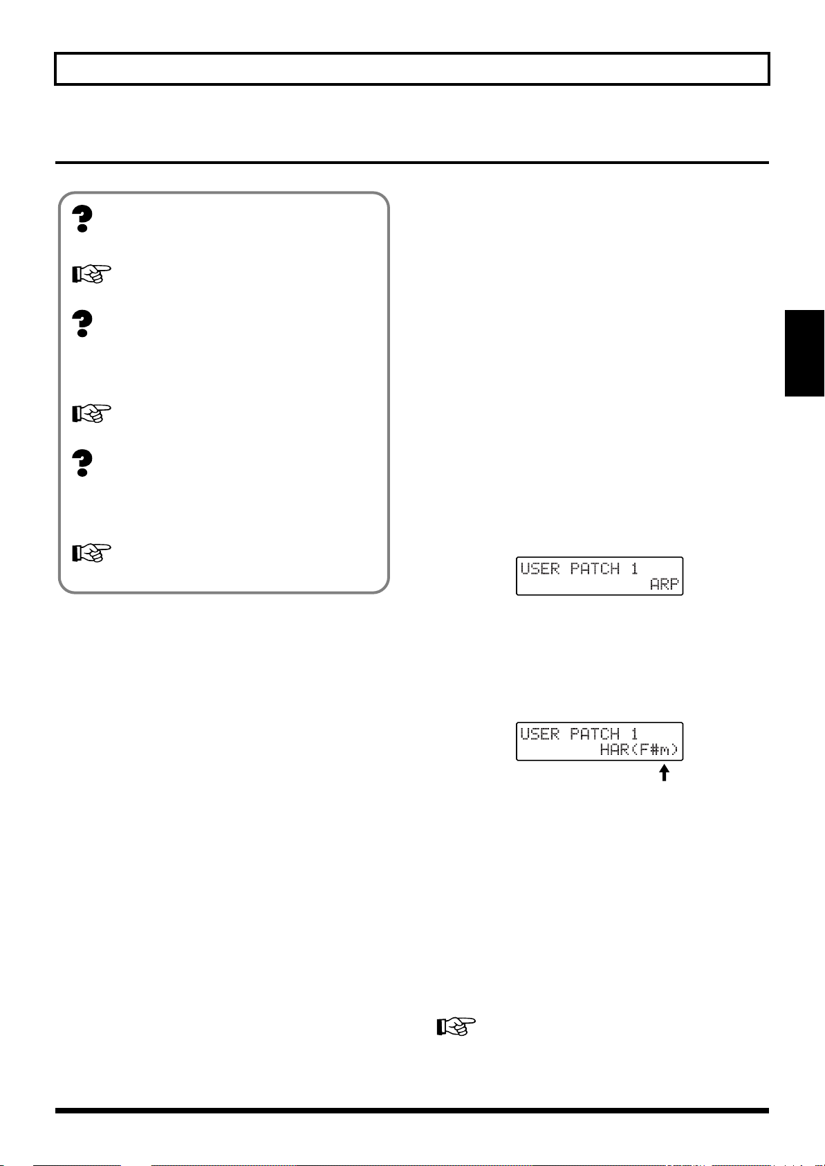
Chapter 3 Controlling Functions and Effects with the Base Module Pedals
Turning Arpeggiator and Harmonist On/Off
■ Using the pedals for on/off switching
1. Enter Pedal Effect mode (p. 26). (As an alternative, set
About MULTI-FX
These are effects for the synthesizer sound.
For details, refer to p. 53.
About Arpeggiator
This is a function that automatically creates arpeggios —
chords whose notes are played in sequence, rather than
simultaneously — when a chord is played.
For details, refer to p. 76.
System mode “S1/S2 ACTION” to “Patch Select” and
return to Play mode.)
2. Press Pedal 4 (CTRL).
The specified function—MULTI-FX BYPASS,
Arpeggiator, or Harmonist—will be switched on or off.
This selection can be made by the Patch Edit mode
“COMMON” setting “CTRL PEDAL” (p. 46).
<Some Notes About the Display>
MULTI FX BYPASS On/Off
“bYP” or “oFF” appears for approximateryone second in
the three-digit display.
Chap.
3
About Harmonist
This creates harmonies in designated keys using either
guitar and synthesizer sounds, or two synthesizer
sounds together.
For details, refer to p. 80.
The GR-33 comes with Multi-Effects, Arpeggiator, and
Harmonist functions that can be turned on and off using the
pedals.
* The MULTI-FX Bypass, Arpeggiator and Harmonist can be
turned on or off individually for each Patch. To learn about
these settings, refer to p. 46.
* You may hear a noise when MULTI-FX BYPASS is switched
on/off, but this does not indicate a malfunction.
Arpeggiator On/Off
“Arp” or “oFF” appears for approximateryone second in
the three-digit display.
The display responds as shown below when the
Arpeggiator is being turned on.
fig.3-10
Harmonist On/Off
“HAr” or “oFF” appears for approximatery one second
in the three-digit display.
The display responds as shown below when the
Harmonist is being turned on.
fig.3-02
Key
Either the Arpeggiator or Harmonist—but not both—can
be selected for a patch. Even when they are turned off,
either the Arpeggiator or Harmonist is still selected.
When the Arpeggiator (Harmonist) is turned on, the
display of the Play mode shows “ARP” or “HAR” to
indicate which one currently selected.. If the harmonist is
selected, the currently selected key will also be
displayed.
* When you want to switch from Arpeggiator in a certain patch
to Harmonist (or vice versa), press [EFFECTS] to change the
“HAR/ARP SELECT” setting.
For more detailed information and instructions for this
procedure, refer to p. 78 and 82.
27
Page 28
Chapter 3 Controlling Functions and Effects with the Base Module Pedals
Changing Effects with the Pedals
In Pedal Effect mode (p. 26), you can get different effects by pressing Pedals 1 to 4 in the follow way.
Getting a Pedal Wah Effect (Wah)
You can get several of the most commonly used wah effects
by pressing Pedal 1 (WAH). Repeatedly pressing and
releasing the pedal produces changes in the sound
resembling those produced by a guitar wah-wah pedal,
allowing you to apply this effect to synthesizer sounds.
You can choose from a number of pre-programmed
variations that use different combinations of rate of sound
change, degree of change, panning, how different the sound
becomes, and so on. These can then be saved in each patch.
In addition, when you select “Modulation” in “WAH TYPE,”
you will hear a deep vibrato (undulating or wavering pitch)
when the pedal is pressed instead of wah-type effects. This
creates the mechanical-sounding vibrato characteristic of
synths — if you prefer, you can create a more naturalsounding vibrato using your guitar fingering.
For more detailed information and instructions for this
procedure, refer to “Selecting Wah Types (WAH TYPE)” (p.
43).
* You may find that when you first press Pedal 1 (WAH), the
sound is different than when the patch was first selected. The
sound may be muffled, or have a strange quality to it. Return
to the original patch, switch to a different patch, and then
return to the original patch again. If a bank shift pedal is
connected, you can return to the original patch by pressing the
bank down pedal while still in Pedal Effect mode.
Changing Pitch Dynamically (Pitch Glide)
Press Pedal 2 (P-GLIDE) to get a pitch glide effect. This effect
creates continuous changes in pitch over variable time
intervals, long or short. With chords—since you can glide
while maintaining the harmonic intervals within the chord—
this differs from a guitar’s vibrato arm/vibrato bar/
whammy bar, providing a unique effect.
As for the time duration and glide intervals, you can select
from seven pre-programmed pitch rise and fall patterns, and
then save them in patches.
Holding a Synth Tone After the String is Stopped (Hold)
Press Pedal 3 (HOLD) to activate the Hold function. When
you use this effect, the synthesizer sound continues to play
even after the guitar string has stopped vibrating.
You can select from a number of variations — hold the
synthesizer chord while the guitar plays a melody, hold only
one of two layered tones, hold only Strings 5 and 6, and more
— and then save them in patches.
For more detailed information and instructions for this
procedure, refer to “Selecting Hold Type (HOLD TYPE)” (p.
45).
* When the arpeggiator is on, the behavior and available
variations for the Hold function are different than when the
arpeggiator is off.
For more detailed information and instructions for this
procedure, refer to “Effective Use of the Hold Function
During Arpeggios” (p. 76).
<Some Notes About the Display>
When Pedal 1 (WAH) is pressed
“UAH” or “Mod” appears in the three-digit display.
When Pedal 2 (P-GLIDE) is pressed
“P.GL” appears in the three-digit display.
When Pedal 3 (HOLD) is pressed
“HLd” appears in the three-digit display.
For more detailed information and instructions for this
procedure, refer to “Selecting Pitch Glide Type (GLIDE
TYPE)” (p. 44).
* Depending on the selected tone, the tone settings, and
performance conditions, the width of the effect may be limited.
28
Page 29
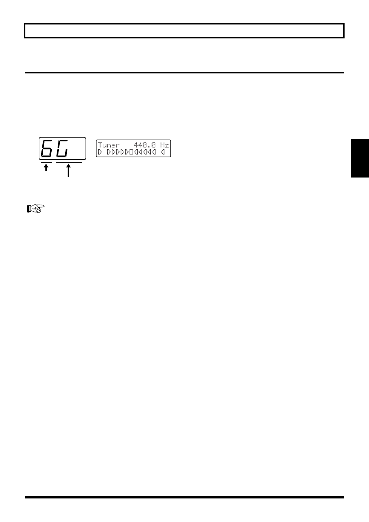
Chapter 3 Controlling Functions and Effects with the Base Module Pedals
Calling Up the Tuner Function with a Pedal
1. While pressing [S1] on the GK-2A, step on Pedal 1
(TUNER).
* Perform this operation with “S1/S2 FUNCTION” set to
“Normal.”
The Tuner function is called up, and the following
appears in the display.
fig.3-03
Chap.
3
String Number
2. Adjust the tuning.
For more detailed information and instructions for tuning,
refer to “Adjusting the Guitar Tuning (Tuner Function)” (p.
18).
3. After you have finished tuning, press any foot pedal or
press [S1] or [S2] on the GK-2A.
You will return to Play mode.
Note Name
29
Page 30
Chapter 4 Five Basic Modes
The three main modes of the GR-33 allow you to:
• Select tones and perform “Play mode”
• Get effects such as wah or hold using the pedal on the
base module “Pedal Effect mode”
• Create and modify patches, and write them into memory
“Patch Edit mode”
Play Mode
In Play mode, the buttons and dials work as follows:
[BANK/PARAMETER] Button
Moves you forward and back through patch banks.
[PLAY] Button
Has no function in this mode.
[SYSTEM] Button
Switches to System mode (settings for the GR-33 itself).
[TUNER] Button
Switches to Tuner mode (p. 18).
[WRITE] Button
Writes the contents of a patch (p. 36).
[COMMON] Button
Switches to Patch Edit mode, COMMON (overall patch
settings).
[TONE] Button
Switches to Patch Edit mode, TONE (sound-related patch
settings).
[EFFECTS] Button
Switches to Patch Edit mode, EFFECTS (effect-related patch
settings).
[STRING SELECT] Button
Has no function in this mode.
[OUTPUT SELECT] Button
Changes the output device selection (p. 19).
• Establish settings for the entire GR-33 “System mode”
• Adjusting the tuning “Tuner mode”
How buttons, dials, and knobs work varies depending on the
mode you are in.
GK-2A [S1]
While this is held down, pedal workings can be changed (p.
22, 29). (TUNER, GROUP ▲, BANK ▲, BANK ▼)
GK-2A [S2]
Switches to Pedal Effect mode (p. 26).
External Bank Shift Pedal
For switching patch banks.
(This does the same thing as BANK ▼ and BANK ▲).
When “S1/S2 FUNCTION” is Set to “Patch
Select”
When “S1/S2 FUNCTION” is set to “Patch Select,” use
the GK-2A’s [S1] and [S2] buttons to move up and down
through the patches. Operation of the following buttons
will differ from normal Play mode as follows.
* Buttons and dials not listed here will function the same
way as in normal Play mode.
Pedal 1–4
Function as in Pedal Effect mode (p. 31).
GK-2A [S1]
Advances through patches.
GK-2A [S2]
Goes back through patches.
External Bank Shift Pedal
Goes forward and back through patches.
[PATCH/VALUE] Dial
Moves forward and back through patches (p. 23).
* If the “DIAL FUNCTION” is set to “VALUE Only,” this
will be ignored.
Pedal 1–4
Switches patches (p. 22).
Expression Pedal
Changes the value of the selected parameter (p. 47).
30
When you want to check something by listening to
patches played in order— or want to toggle between a
pedal effect such as hold, and a patch—this is a
convenient way to do so without having to switch
modes. With PATCH INC/DEC BY S1/S2 selected,
patch numbers are shown in the display, with “PdL”
appearing about once every four seconds.
Page 31

Pedal Effect Mode
Chapter 4 Five Basic Modes
In Pedal Effect mode, buttons and dials work as follows.
Additionally, you can change the nature of the available
effects by pressing Pedals 1 to 4 in each patch. You can also
change and re-record effects settings in User Patches A11 to
d84.
[BANK/PARAMETER] Button
Goes forward and back through banks.
[PLAY] Button
Returns you to Play mode.
[SYSTEM] Button
Switches to System mode (settings for the GR-33 itself).
[TUNER] Button
Switches to Tuner mode (p. 18).
[WRITE] Button
Writes the contents of a patch (p. 36).
[COMMON] Button
Switches to Patch Edit mode, COMMON (overall patch
settings).
[TONE] Button
Switches to Patch Edit mode, TONE (sound-related patch
settings).
[EFFECTS] Button
Switches to Patch Edit mode, EFFECTS (effect-related patch
settings).
[STRING SELECT] Button
Has no function in this mode.
Pedal 1
WAH → Adds effects such as a wah pedal-like sound or
mechanical-sounding vibrato.
Pedal 2
P-GLIDE → Adds pitch glide, an effect that creates wide,
smooth changes in pitch.
Pedal 3
HOLD → Causes synthesizer sounds to continue to play
even after the guitar string has stopped vibrating.
Pedal 4
CTRL → Turns the MULTI-FX BYPASS, the arpeggiator (p.
76) and harmonist (p. 80) on and off. Is also used as an
auxiliary pedal for holding arpeggios (p. 76).
Expression Pedal
Changes the value of the selected parameter (p. 47).
GK-2A [S1] and [S2]
Press either of these to return to Play mode.
External Bank Shift Pedal (Bank Up)
This is used for the arpeggiator’s Tap Tempo Teach function
(p. 79). Also toggles between major and minor when using
harmonist (p. 85).
External Bank Shift Pedal (Bank Down)
Returns sounds that have been changed with the wah
function back to the way they sounded when the patch was
first selected. (Returns to the original sound even after
normal patch-switching procedures.)
Chap.
4
[OUTPUT SELECT] Button
Changes the output device selection (p. 19).
[PATCH/VALUE] Dial
Goes forward and back through patches (p. 23).
* If “DIAL FUNCTION” is set to “VALUE Only,” this will be
ignored.
31
Page 32

Chapter 4 Five Basic Modes
Patch Edit Mode: What It Means, How It Works
In this mode, you can program patches.
Patch Edit mode is divided into three sections: COMMON,
TONE, and EFFECTS.
fig.4-01
Patch Edit mode
EFFECTSTONECOMMON
• COMMON
This is where you name a Patch or set up pedal effects.
• TONE
This is where you set up the tones that serve as the basis
for synth sounds.
• EFFECTS
This is where you can set up reverb, chorus and multieffects. Arpeggiator and Harmonist settings are also
made here.
In Patch Edit mode, the buttons and dials work as follows:
[BANK/PARAMETER] Button
Use these buttons to select the parameter that you wish to
adjust.
[PLAY] Button
Returns you to Play mode.
[SYSTEM] Button
Switches to System mode (settings for the GR-33 itself).
[TUNER] Button
Switches to Tuner mode (p. 18).
[EFFECTS] Button
Switches to Patch Edit mode, EFFECTS (effect-related patch
settings).
* If you are already viewing EFFECTS settings, pressing
[EFFECTS] will turn the bypass function on/off (p. 75).
[STRING SELECT] Button
When adjusting a parameter that can be set independently
for each string, use this button to select the string with which
you want to work (p. 35).
* For parameters that are not set independently for each string,
this button will have no effect.
[OUTPUT SELECT] Button
Changes the output device selection (p. 19).
[PATCH/VALUE] Dial
Changes the value for the selected parameter.
Pedal 1–4
Used as auxiliary pedals in making any number of settings,
and for confirming effects.
Expression Pedal
Used as auxiliary pedal in making any number of settings,
and for confirming effects (p. 47).
GK-2A [S1] and [S2]
Changes the value for the selected parameter.
External Bank Shift Pedal
Changes the value for the selected parameter.
[WRITE] Button
Writes the contents of a patch (p. 36).
[COMMON] Button
Switches to Patch Edit mode, COMMON (overall patch
settings).
* In the COMMON (concerned with patch settings) Patch
Name Setting screen you can use this to switch between
uppercase and lowercase characters (p. 38).
[TONE] Button
Switches to Patch Edit mode, TONE, (sound-related patch
settings).
* In TONE (concerned with the sound of patches), pressing
[TONE] will switch you between the 1ST and 2ND settings
item.
32
In Patch Edit mode, when you have modified even one
parameter of the selected patch, the three-digit display will
change. The decimal point of the lowest digit will light to
indicate that the patch’s settings have been modified.
fig.4-02
Patch Edit mode
Period
If you wish to save the new settings, perform the Write
operation (p. 36).
* If you change patches without performing the Write operation,
your edits will be lost.
Page 33

System Mode
Chapter 4 Five Basic Modes
In this mode you can make settings for the entire GR-33 —
i.e., settings that do not change when you switch patches —
such as input sensitivity and display brightness.
In System mode, the buttons and dials work as follows:
[BANK/PARAMETER] Button
Use these buttons to select the parameter that you wish to
adjust.
[PLAY] Button
Returns you to Play mode.
[SYSTEM] Button
Has no function in this mode.
[TUNER] Button
Switches to Tuner mode (p. 18).
[WRITE] Button
Writes the contents of a patch. This is disabled during
“BULK LOAD” (p. 37). It is used for initiating procedures
and for confirmation in “BULK DUMP” and “FACTORY
RESET” (p. 37, 16).
[COMMON] Button
Switches to Patch Edit mode, COMMON (overall patch
settings).
[TONE] Button
Switches to Patch Edit mode, TONE (sound-related patch
settings).
[EFFECTS] Button
Switches to Patch Edit mode, EFFECTS (effect-related patch
settings).
[STRING SELECT] Button
Has no function in this mode.
[OUTPUT SELECT] Button
Changes the output device selection (p. 19).
[PATCH/VALUE] Dial
Changes the value for the selected parameter.
Pedal 1–4
Has no function in this mode.
Expression Pedal
Changes the value of the selected parameter (p. 47).
GK-2A [S1] and [S2]
Changes the value for the selected parameter.
External Bank Shift Pedal
Changes the value for the selected parameter.
Chap.
4
Procedures in Tuner Mode
In Tuner mode, the buttons and dials work as follows.
[BANK/PARAMETER] Button
Has no function in this mode.
[PLAY] Button
Returns you to Play mode.
[SYSTEM] Button
Switches to System mode (settings for the GR-33 itself).
[TUNER] Button
Has no function in this mode.
[WRITE] Button
Has no function in this mode.
[COMMON] Button
Switches to Patch Edit mode, COMMON (overall patch
settings).
[TONE] Button
Switches to Patch Edit mode, TONE (sound-related patch
settings).
[EFFECTS] Button
Switches to Patch Edit mode, EFFECTS (effect-related patch
settings).
[STRING SELECT] Button
Has no function in this mode.
[OUTPUT SELECT] Button
Changes the output device selection (p. 19).
[PATCH/VALUE] Dial
Changes the value for the “MASTER TUNE”.
Pedal 1–4
Exits Tuner mode and returns you to Play mode.
Expression Pedal
Changes the value of the selected parameter (p. 47).
GK-2A [S1] and [S2]
Exits Tuner mode and returns you to Play mode.
External Bank Shift Pedal
Exits Tuner mode and returns you to Play mode.
33
Page 34

Chapter 4 Five Basic Modes
Getting Into and Out of Each Mode
Here we will explain how to get into and out of each of the
five modes: Play mode, Pedal Effect mode, Patch Edit mode,
System mode and Tuner mode.
fig.4-03
Play mode
System mode
Patch Edit mode
COMMON[COMMON
TONE
EFFECTS[EFFECTS
Tuner mode
[
PLAY
[S2]
]
Pedal Effect mode
[
SYSTEM
[
TONE
[
TUNER
]
]
]
]
]
For modes other than Pedal Effect mode, you can press a
single button on the GR-33 to enter the desired mode from
any other mode. The following diagram shows the buttons
corresponding to each mode, and the state of the three-digit
display for each mode.
GK-2A’s
Play mode
Patch Edit mode
COMMON[COMMON
TONE
EFFECTS[EFFECTS
System mode
Tuner mode
[
PLAY
[S2]
][
Pedal Effect mode
]
[
]
TONE
]
[
SYSTEM
[
TUNER
]
]
S2
]
* Pedal Effect mode can be entered only from Play mode.
* If “S1/S2 FUNCTION” is not set to “Normal,” it will not be
possible to enter Pedal Effect mode.
34
Page 35

Chapter 5 Setting/Changing Sounds (Patches)
Details of Putting a Patch Together
Every patch is constructed as shown in the following figure.
fig.5-01
128 Preset Patches
E11 – H84
128 User Patches
A11 – D84
A11
2nd TONE
1st TONE
Tone Selection
#1 – #384
(Piano, Organ, etc.)
Tone Adjustment
•Attack
•Release
•Brightness
•Layer
Layering of 1st and
2nd Tones
•Transpose 1st
•Transpose 2nd
It's possible to make settings
to each string individually.
•1:2BALANCE
1st/2nd Level Balance
What is a “Tone”?
As shown in the above figure, you can select any two of the
384 built-in tones—the raw material for synth sounds—and
use them in a patch.
The two tones in a patch are called the “1st tone” and the
“2nd tone.”
You can assign the selected tones separately to individual
strings, and then layer them (p. 51). You can also adjust
parameters such as attack (p. 49), release (p. 50), brightness
(p. 50), and transpose (p. 51). In addition, you can also
independently select a transposition (TRANSPOSE) for each
string.
In addition to tone selections, tone settings can be saved in
patches.
TONE
TONE MIX
•Arpeggio and harmony settings
•Reverb/Chorus settings
•Multi FX settings
EFFECTS
COMMON
•
Patch Name and Level settings, etc.
•Pan settings
•Pedal settings
•MIDI settings
Making separate settings for each string (STRING SELECT)
Three of the TONE parameters—“LAYER,” “1ST
TRANSPOSE,” and “2ND TRANSPOSE—and the four
COMMON parameters—“MIDI [PC],” “MIDI [CC0],” “MIDI
[CC32],” and “MIDI [TRANSPOSE]”—can be set separately
for each string using the [STRING SELECT] button.
When you press [STRING SELECT], the three-digit display
will indicate the selected string as follows.
fig.5-02
All strings selected
Strings 5 and 6 selected
String 1 selected
String 2 selected
Chap.
5
Recording and Settings of Each Patch
Besides patch tone-selection and string assignments—as well
as tone settings—you can set and store the following items in
a patch, as well as other items.
• Patch name (p. 38)
• How effects are applied (p. 53)
• Arpeggiator patterns and related settings (p. 76)
• Harmonist settings (p. 80)
• What happens when you step on a pedal (p. 43)
• Program numbers sent to external MIDI devices (p. 88)
• External sound generator transpositions (p. 51)
For more information about these settings, please consult the
reference pages listed above for each item.
String 6 selected
String 5 selected String 4 selected
To set each string independently, press the [STRING SELECT]
button to select the desired string, and then turn the [VALUE]
dial to change the currently selected parameter’s setting. For
example, if you use the [STRING SELECT] button to select “5,”
and then turn the [VALUE] dial, the currently selected
parameter’s setting will change only for String 5. You can
continue and adjust the settings for the other strings using the
same method.
* If you use the [STRING SELECT] button to select “ALL” or
“6-5,” the parameter’s value may blink, signifying that the
settings for the selected strings are different from one another.
If you turn the [VALUE] dial to select a value, the value will
be applied to each selected string: to all strings if “ALL” is
displayed, or to Strings 5 and 6 if “6-5” is displayed.
String 3 selected
35
Page 36

Chapter 5 Setting/Changing Sounds (Patches)
The Relationship Between Arpeggiator/ Harmonist and Patches
When you are playing, you can use the arpeggiator or the
harmonist. For each patch, you can select one of these
functions (p. 78, 82) and also determine whether or not it will
be active (p. 77, 81) when the patch is selected.
Likewise, you can select arpeggio patterns—the sequence of
strings that the arpeggiator function creates and plays—for
each patch individually from among the available 50
patterns.
For more details about making these settings, refer to
“Selecting Arpeggio Patterns (ARP PATTERN)” (p. 79).
Saving Patches
Generally, you create and modify patches by using
[PARAMETER] to select parameters in Patch Edit mode, and
turning [VALUE] to select the desired values.
It is important to remember that if you simply switch to
another patch, the changes you have made will be lost, and
the edited patch will revert to its original state. (The lowest
decimal point in the three-digital display lights (p. 32) to
warn you of this.) To save any changes you have made, use
the following steps to perform the Patch Write operation
before changing to another patch.
■ Performing a Patch Write
1. Press [WRITE]—you enter Write mode, and a screen
like the one shown below appears.
fig.5-04
2. Turn [VALUE] to choose the patch location to which
you want to save the patch.
fig.5-05
4. After making sure that you want to complete this
fig.5-07
* To cancel the operation, press [PLAY].
Once you have performed these steps, the changes you have
made to the patch will be recalled when that patch is
selected, even if you switch to another patch or turn the
power off.
* If you write without designating a location where the patch is
* As Patch Groups E through H are read-only, you cannot
operation—and that you are ready to write over the
patch currently in the selected destination location—
press [WRITE] once again.
“Now Writing...” appears in the display. In a moment,
the GR-33 automatically returns to Play mode,
completing the writing procedure.
to be saved, you will overwrite the original version of the
patch, and that version of the patch will be discarded.
overwrite them by saving a patch to their locations.
3. After you have specified the writing destination, press
[WRITE].
The following confirmation screen appears.
fig.5-06
36
Cautions When Saving
With Patch Write, the patch is written the way it actually
sounds at the time you write it, and this includes whether the
Arpeggiator or Harmonist functions are turned on or off.
However, temporary tone changes made with the base
module pedals, such as wah and pitch glide, or those from
external expression pedals, will not be saved. This also
applies to the temporary switching off of internal effects
using the effect bypass function (p. 75).
* You do not have to manually save the System mode
parameters that apply to the entire GR-33. Changes made to
these settings are saved automatically, and are stored even
after the power is turned off.
Page 37

Chapter 5 Setting/Changing Sounds (Patches)
Saving Patches From the GR-33 to Sequencers or Other MIDI Devices (Bulk Dump)
Settings for all user patches—as well as all system settings—
can be transferred in and out of the GR-33 using MIDI. You
can also save patches externally to equipment that can record
MIDI data. For this kind of operation, the GR-33 uses MIDI
messages called “System Exclusive messages,” or “SysEx”
messages. Each System Exclusive message can be interpreted
only by the device for which it is intended.
SysEx data sent from the GR-33, data read from a floppy
disk, or data entered by other means can be stored in a MIDI
sequencer using the sequencer’s realtime recording or bulk
librarian function. You can also send/receive SysEx data
directly from one GR-33 to another by connecting the two via
MIDI.
■ Sending System Settings or Patch Data to
an External MIDI Device
1. Turn off the power to the GR-33.
2. Connect the GR-33’s MIDI OUT to the MIDI IN
connector on the external MIDI device.
3. Turn on the power of the GR-33.
4. Press [SYSTEM] to enter System mode.
5. Press [PARAMETER] to select “BULK DUMP.”
fig.5-08
fig.5-09
9. Sending is complete when the GR-33’s previous
display returns. If a sequencer is on the receiving end
of a transfer, stop recording at this point.
fig.5-0
10.Press [PLAY] to return to Play mode.
Receiving previously saved system or patch data (Bulk Load)
Here’s how you can receive system or patch data from an
external device capable of recording MIDI data, or from
another GR-33.
* Exclusive messages can be received only in the Bulk Load
screen.
■ Receiving system settings or patch data
from an external MIDI device
1. Turn off the power to the GR-33.
2. Connect the external MIDI device MIDI OUT to the
MIDI IN connector on the GR-33.
Chap.
5
6. Turn [VALUE] to select the type of data you wish to
transmit.
All: All user patches and system settings
System: System settings
User Patch: All user patches (128 patches)
Patch Group A: The 32 patches A11 to A84
Patch Group B: The 32 patches B11 to B84
Patch Group C: The 32 patches C11 to C84
Patch Group D: The 32 patches D11 to D84
Patch A11: Patch A11 only
Patch A12: Patch A12 only
: :
Patch D84: Patch D84 only
7. Put the external MIDI device in record mode. For
example, start a MIDI sequencer’s realtime recording.
8. Press [WRITE].
The selected data is transmitted from the GR-33 to the
external device. While data is being transmitted, the GR-
33 display shows “Now Sending... .”
3. Turn on the power of the GR-33.
4. Press [SYSTEM] to enter System mode.
5. Press [PARAMETER] to select “BULK LOAD.”
fig.5-40
6. Transmit the data from the external device.
fig.5-41
When reception is finished, the previous display will
reappear.
fig.5-40
37
Page 38

Chapter 5 Setting/Changing Sounds (Patches)
7. Press [PLAY] to return to Play mode.
* If you send data for a single patch to the GR-33, you will need
to perform the Patch Write operation (p. 36) on the GR-33 to
store the patch in a patch memory location. When writing the
received patch, you can specify the desired destination, so you
are not forced to overwrite the same-numbered patch if it is one
you wish to keep.
* Except for the receiving of A11 through D84 as single patches,
* Since data can be lost should unexpected events occur, we
Naming the Patches (PATCH NAME)
You can assign a name of up to twelve characters to each
patch. Assign a name that will help you remember the
sound, or the song for which the patch is intended.
■ Assigning a Name to a Patch
1. Select the patch whose name you want to change, and
press [COMMON] to enter Patch Edit mode.
2. Press [PARAMETER] to select “PATCH NAME.”
fig.5-10
4. Turn [VALUE] to select the desired character, number
fig.5-11
* You can press [COMMON] to switch between uppercase and
no special conditions apply for storing patch or system
parameter data received via SysEx.
strongly recommend regularly using the Bulk Dump feature to
back up your GR-33 data.
or symbol.
Space
—
—
—
lowercase characters.
5. Repeat Steps 3 and 4 to complete the name.
Cursor
3. Use [PARAMETER] to move the cursor to the character
you wish to modify.
6. Press [WRITE] to perform the Patch Write operation (p.
36).
* After performing the Patch Write operation, you will
automatically return to Play mode.
* If you don’t wish to save the Patch’s new name, press [PLAY]
to return to Play mode instead of pressing [WRITE].
Setting the Volume Level of Each Patch (PATCH LEVEL)
For things like switching between multiple patches while
playing, having the volume of backing patches set lower than
the volume of solo patches is a convenient feature. You can
make these kinds of volume settings by recording the patch
level (PATCH LEVEL) of each patch.
■ Determining and Recording Patch Volumes
1. Select the patch whose volume you want to change, and
press [COMMON] to enter Patch Edit mode.
2. Press [PARAMETER] to select “PATCH LEVEL.”
fig.5-12
3. Use [VALUE] to change the value.
The value changes within a range of 0 to 100. A setting of
“0” silences to patch, and “100” sets it to maximum
volume.
4. Press [WRITE] to perform the Patch Write operation (p.
36).
* After performing the Patch Write operation, you will
automatically return to Play mode.
* If you don’t want to save the Patch, press [PLAY] to return to
Play mode.
* Even with PATCH LEVEL values the same, volume levels
may change according to other settings. In the example below,
the level has been set high. If PATCH LEVEL is then set to a
low level, the balance of another patch is used. (The
combination of the settings shown below may cause
excessively high volume levels, so be careful not to allow this to
result in damage to amps and speakers.)
38
Page 39

Chapter 5 Setting/Changing Sounds (Patches)
• When both the first and second tones are present.
• When the Reverb send level or Chorus send level is set to
a high level.
• When a high volume level is a characteristic of the tone
itself.
• When the brightness setting value is high.
• When wah effects are applied.
Changing the Feel of a Performance (PLAY FEEL)
Guitars differ from keyboards and other instruments in that
the part of the instrument that actually vibrates (i.e. the
string) is touched directly, allowing subtle control of the
power with which it is played. To let the guitar synthesizer
make maximum use of this feature, it is necessary to set the
“playing response.”
This selection is made with “PLAY FEEL” in the COMMON
setting of Patch Edit mode. For example, by changing the
Play Feel options like “finger picking” or “normal picking,”
you can get very natural-sounding expression of how much
power is in the playing.
■ Changing and Recording Play Feel
1. Select the patch whose PLAY FEEL you want to change,
and press [COMMON] to enter Patch Edit mode.
Finger (finger picking):
The setting for when you want to perform with the feeling
finger picking provides. Sensitivity is a little higher than with
normal picking.
Hard (hard picking):
This setting is for those who pick rather hard, and the
sensitivity is a little lower than with normal picking.
* When there is a problem with the guitar’s arrangement, and
the only places GK-2A’s divided pickup can be installed are too
close to the strings, you may be able to improve the behavior
with the settings in each patch.
Soft (soft picking):
For picking that is a little weaker. Sensitivity is a little higher
than with normal picking.
Chap.
5
2. Press [PARAMETER] to select “PLAY FEEL.”
fig.5-13
3. Use [VALUE] to change the value.
* For a detailed explanation, see the subsequent section, “The
PLAY FEEL settings and their effects.”
4. Press [WRITE] to perform the Patch Write operation (p.
36).
* After performing the Patch Write operation, you will
automatically return to Play mode.
* If you don’t want to save the Patch, press [PLAY] to return to
Play mode.
◆ The PLAY FEEL settings and their effects
There are eight settings ("Normal,” “Finger,” “Hard,” “Soft,”
“Tapping,” “No Dynamics,” “Envelope1,” “Envelope2"), and
eight settings that add the Accel function to each of these
("Accl Normal,” “Accl Finger,” “Accl Hard,” “Accl Soft,”
“Accl Tapping,” “Accl No Dynamics,” “Accl Envelope1,”
“Accl Envelope2").
These meanings are as follows:
Normal:
General picking, thus the standard setting for play.
Tapping (tapping play):
When making use of many kinds of picking techniques, such
as tapping play (or “right-hand play”), pulling-off, or
hammering-on, this setting provides very stable sound
expression. The range of power that can be expressed is a bit
narrow.
No Dynamics (no dynamics):
With this setting, no matter how hard or softly you play, you
get uniform volume and tone. Use this setting with tones like
Synth Lead or Organ when you want to transmit a feeling
without expression.
Envelope1 (envelope follow type1):
This is for setting how much the synthesizer volume
influences the amplitude of the strings.
For details, see the subsequent section, “Following the Guitar
Sound Shape (Envelope Follow).”
Envelope2 (envelope follow type2):
This is for setting how much the overall tone (brightness) is
influenced by the amplitude of the strings.
For details, see the subsequent section, “Following the Guitar
Sound Shape (Envelope Follow).”
39
Page 40

Chapter 5 Setting/Changing Sounds (Patches)
The eight types “Accl Normal,” “Accl Finger,” “Accl Hard,”
“Accl Soft,” “Accl Tapping,” “Accl No Dynamics,” “Accl
Envelope1,” and “Accl Envelope2” add the Accel function to
the previously listed eight types. Notes will sound more
quickly than the first eight types.
For details, refer to “Increasing the Speed of Expression
(Acceleration)” (p. 40).
* Picking strength and power range vary from player to player.
The names of these settings (“normal,” “soft,” “hard,” and so
on) are for easy reference only, so you are encouraged to
actually switch through the settings, and when you find ones
that you feel are easy to play, that you feel have characteristics
of instruments you’d like to play, paying no special attention
to their names, go ahead and select those settings.
Following the Guitar Sound Shape (Envelope Follow)
When you select the “Envelope1” and “Envelope2” settings
in the above PLAY FEEL section, the envelope follow
function comes on, giving you that effect.
In this condition, changes in the strings’ amplitude (changes
due to picking, or from how the sound decays) are
influenced by the volume or tone of the synthesizer sounds.
You can get the following types of effects.
Envelope1 (envelope follow type1):
Here, the synthesizer volume influences the amplitude of the
strings. You can get a natural feel when using decay tones
(from guitars, electronic pianos, and so forth), so do try this
setting. (Change in the synth sound’s volume is a little more
compressed, a bit more restrained than that of the guitar.
Envelope2 (envelope follow type2):
This is for setting how much the overall tone (brightness) is
influenced by the amplitude of the strings. Along with the
decay, which depends on the picking strength and time
elapsed, this setting changes the sound’s brightness
(regulation of muffled sound) dynamically. Especially with
Synth Lead tones, you can get that tone’s characteristic effect.
The following procedure, combined with the wah auto wah
function, you can get a touch wah effect with extremely
smooth response.
■ Getting a Touch Wah Effect with the PLAY
FEEL “Envelope2” Setting
1. Let’s select a synth lead patch.
2. Press [COMMON], use [PARAMETER] to move the
cursor to “PLAY FEEL,” and use [VALUE] to Select
“Envelope2.”
3. Press [PARAMETER] to select “WAH TYPE.”
4. Use [VALUE] to select “AutoWah1–5.”
For more details on WAH TYPE, refer to “Selecting Wah
Types (WAH TYPE)” (p. 43).
5. Play the guitar to confirm that the wah effect is
responding to the strength of the picking.
* To save the settings in patches, press [WRITE] to perform the
Patch Write operation (p. 36).
* When “Envelope1” or “Envelope2” is selected for PLAY
FEEL, the envelope follow data will be sent from MIDI OUT
as controller no. 18 (general purpose controller 3).
Increasing the Speed of Expression (Acceleration)
When you are making selections in PLAY FEEL (p. 39), when
items containing “Accl” in the lower right corner of the
display are selected, the GR-33’s “Acceleration Function” is
turned on. When put in this mode, the average speed from
picking to sound is higher than usual.
However, when this function is being used, the effect of
internal processing of string noise abatement is weakened.
This means that for some tones, you may hear noise or pitch
change when you pluck the string. If you use the Accelerator
function, please confirm when you’re creating a sound that
there is no bothersome noise in the tone you are using.
40
Page 41

Chapter 5 Setting/Changing Sounds (Patches)
Changing Sound Placement (PAN)
You can pan each of a patch’s two tones to its own stereo
location. For example, you can pan one tone to the far left in
the stereo field, and the other to the far right.
You can also create complex stereo movement using a variety
of pre-programmed stereo effects. This is done using the
COMMON “PAN MODE” and “PAN” settings in Patch Edit
mode.
■ Setting and Saving Sound Placement
1. Select the patch whose pan position you want to set,
and press [COMMON] to enter Patch Edit mode.
2. Press [PARAMETER] to select “PAN MODE.”
fig.5-14
3. Use [VALUE] to select the desired pan mode.
* For more details, see the subsequent section, “Available value
for PAN, and their effects.”
* If you are not using Normal or Cross Tones, proceed to step 6.
4. Press [PARAMETER] to select “PAN.”
fig.5-15
Cross Tones:
With the setting at “0,” the selected tone is placed in the
center of the stereo field. By changing the values across a
range of -50 to 50, the tone’s position shifts left or right: when
a tone is set to 50, it is panned all the way to the right; setting
it to -50 pans it all the way to the left. Therefore, by
programming a patch with one tone set to 50 and the other to
-50, you can create a rich, widespread stereo sound.
1-6, 6-1:
With this setting, each string is panned separately. When you
select 1-6, the strings’ sounds are placed in sequence from the
left: String 1, String 2, all the way up to String 6. Conversely,
with 6-1, the opposite positioning is used, i.e. String 6, String
5, all the way down to String 1.
Odd-Even, Even-Odd (Odd, Even):
This setting separates odd- and even-numbered strings, and
places them left and right. With Odd-Even, the oddnumbered strings—1, 3, and 5—are panned left, and the
even-numbered strings—2, 4, and 6—panned right. “EvenOdd” will produce the same effect as if “Odd-Even” were
exchanged left to right.
Random Both, Random 1st, Random 2nd:
The stereo placement of the 1st and 2nd tones changes
randomly. “Random 1st” and “Random 2nd” cause only the
corresponding tone to move around randomly—the other
tone is placed in the center.
Chap.
5
5. Turn [VALUE] to select the desired value.
6. Press [WRITE] to perform the Patch Write operation (p.
36).
* After performing the Patch Write operation, you will
automatically return to Play mode.
* If you don’t want to save the Patch, press [PLAY] to return to
Play mode.
◆ Available values for PAN, and their effects
Normal:
With a setting of 0, all sounds will be panned to the center.
Changing the value within the range from -50 through 50
will cause the panning to change correspondingly. Both the
1st and the 2nd tone will be panned to the far right with a
setting of 50, or to the far left with a setting of -50.
Alternate Both, Alternate 1st, Alternate 2nd:
The perceived location of the 1st and 2nd tones assigned to
each string is panned alternately to the left and right each time
a tone is sounded. For patches having only one tone playing,
the tone moves back and forth repeatedly. With a patch using
both tones—but with the 1st tone to the right and the 2nd tone
to the left—a special stereo effect is created that differs from
what you get with the Random setting.
“Alternate 1st” and “Alternate 2nd” causes only the
corresponding tone to jump back and forth—the other tone is
placed in the center.
* Pan settings have no effect on the internal reverb and chorus.
* You can hear the selected panning effect only through
equipment that can produce stereo sound— and is connected
to the GR-33’s MIX OUT using two cables—or when using
stereo headphones.
* The PAN setting made here is ignored if you have a monaural
type of MULTI-FX selected.
41
Page 42

Chapter 5 Setting/Changing Sounds (Patches)
Dividing Continuous Pitch Changes into Semitones (CHROMATIC)
The GR-33 faithfully reproduces the slight pitch changes and
in-between notes you get from fingering your guitar’s
strings.
However, should the need arise, you can also limit this subtle
pitch response to semitone changes only. This is called the
Chromatic function, and is turned on and off using the
COMMON “CHROMATIC” setting in Patch Edit mode.
fig.5-16
Change in Synth
sound pitch
Major 3rd
minor 3rd
Major 2nd
minor 2nd
(semitone)
minor 2nd
2nd
Chromatic on
Chromatic off
minor 3rd
Actual pitch change
when bending
3rd
■ Turning the Chromatic Function On and Off
and Saving It to Patches
1. Select the patch you want to change, and press
[COMMON] to go into Patch Edit mode.
2. Press [PARAMETER] to select “CHROMATIC.”
fig.5-17
◆ Chromatic Settings and Available Effects
Off (Chromatic Off):
For guitar bending and vibrato, this setting allows you to
make synth sounds faithfully reproduce subtle played pitch
changes of less than a semitone.
When you select any setting other than Off, pitch changes are
limited to semitones.
Type1:
If the pitch is changed smoothly, for example by bending the
guitar string, the pitch will change in semitone steps. When
the pitch changes, the currently-heard sound will not stop; it
will merely change in pitch. There is no separate attack
sound when the pitch changes—this is a change similar to
the one you hear with the slurred playing of a recorder.
Type2:
If the pitch is changed smoothly, the pitch will change in
semitone steps. When the pitch changes, the sound for the
new pitch will be started over, or “retriggered.” Thus,
whenever the pitch changes, you will hear a new attack. If
the retrigger occurs as a string’s vibration is trailing off
(decaying), the retriggered note will play at an appropriately
reduced volume.
Type3:
This is basically the same effect as “Type2,” except that the
retriggered sound level is not influenced by the current state
of the string’s vibration.
3. Turn [VALUE] to select the desired setting.
* For a detailed explanation, see the subsequent section,
“Chromatic Settings and Available Effects.”
4. Press [WRITE] to perform the Patch Write operation (p.
36).
* After performing the Patch Write operation, you will
automatically return to Play mode.
* If you don’t want to save the Patch, press [PLAY] to return to
Play mode.
When You Want to Make a Chord Resonate Beautifully
Due to subtle pitch changes resulting from the way each
string is pressed, with patches using long notes, chords may
end up sounding muddy. If this occurs, turn Chromatic on so
that only pure semitones are heard, thus producing a
beautifully in-tune chord. If you select “Type1,” pitch
differences will be barely audible, creating a naturalsounding resonance.
When You Want to Reproduce Piano-like Pitch Changes
In patches that emulate instruments which do not use pitch
changes smaller than a semitone, Chromatic allows you to
more easily imitate the instrument’s sound. In such cases,
when “Type2” or “Type3” is selected, the attack is
reproduced with each pitch change. (Depending on the tone
or melody, there may be times when “Type1” or Off” yield a
better effect, so select the setting you like best.)
42
Page 43

Chapter 5 Setting/Changing Sounds (Patches)
Selecting Wah Types (WAH TYPE)
There are 35 types, in seven groups, of wah effects you can
get by stepping on and releasing pedal 1 in Pedal Effect
mode, with differing ranges of tone change and different
speeds, and along with one type of modulation (vibrato),
there are a total of 36 variations of wah pedal effects.
■ Selecting Wah (or Modulation) Type
1. Select the patch whose effect type you want to change,
and press [COMMON] to go into Patch Edit mode.
2. Press [PARAMETER] to select “WAH TYPE.”
fig.5-18
3. Use [VALUE] to change the setting.
* For a detailed explanation, see the subsequent section, “Wah
Pedal Variations that can be selected in WAH TYPE.”
* When making settings, play the guitar with pressing pedal 1
to try the effect.
4. Press [WRITE] to perform the Patch Write operation (p.
36).
* After performing the Patch Write operation, you will
automatically return to Play mode.
* If you don’t want to save the Patch, press [PLAY] to return to
Play mode.
◆ Wah Pedal Variations that can be selected
in WAH TYPE
The digit (1–5) at the end of the displayed type name
indicates the speed at which the tone will change. When you
step on and release the pedal, the numbers show, with “1”
indicating the fastest tone change, and as these numbers get
larger, the speed decreases.
fig.5-19
Wah1–5:
This adds an effect that resembles a guitar wah pedal to the
synthesizer sound. With this unique effect added to the
sound, stepping on the pedal gives the tone a brighter “wah”
sound, and when the pedal is released, the sound becomes
darker, with an “oww” sound. By repeatedly stepping on
and releasing the pedal, you can get an effect that sounds like
“wah wah wah.”
AutoWah1–5:
This is basically the same effect as the wah pedal (Wah 1–5),
but rather than being applied with the pedal, with this novel
method, the effect is automatically applied each time the
guitar is picked. In this situation, the pedal still works to add
affect, so you can use both of these options together. When
combined with the Play Feel setting “Envelope2” on tones
like Synth Bass, you can get a smooth “touch wah” effect.
For details on setting the “touch wah” effect, refer to
“Following the Guitar Sound Shape (Envelope Follow)” (p.
40).
Brightness1–5:
This controls only the brightness of the sound, without
adding the characteristic sound of the wah itself. In all other
actions, it is absolutely identical to Wah 1 to 5.
NarrowWah1–5:
This compresses the tone difference from stepping on and
releasing the pedal to half the range of the normal wah (Wah
1 to 5). In all other actions, it is absolutely identical to Wah 1
to 5.
R.Wah1–5 (Reverse Wah 1–5):
This reverses the tones from stepping on and releasing the
pedal in normal wah (Wah 1 to 5) (i.e. step → dark sound,
release → bright).
R.Brightness1–5 (Reverse Brightness 1–5):
This reverses the tones from stepping on and releasing the
pedal in the brightness setting (Brightness 1 to 5) (i.e. step →
dark sound, release → bright).
Chap.
5
Press Release
Tone
Brightness
Examples of Wah1 to Wah5, Brightness1 to Brightness5, etc.
(Changes over time)
Time
R.NarrowWah1–5 (Reverse Narrow Wah 1–5):
This reverses the tones from stepping on and releasing the
pedal in Narrow (NarrowWah 1 to 5) (i.e. step → dark sound,
release → bright).
Modulation:
When you select this setting, as you step on the pedal, then
rather than a wah-type effect, a deep vibrato (wavering
pitch) effect is added. Differing from the mood created by
playing finger vibrato on the guitar, it gives a mechanical,
synthesizer-sounding vibrato.
The speed and depth of the vibrato you get with this function
is predetermined for each tone.
43
Page 44

Chapter 5 Setting/Changing Sounds (Patches)
* If you use wah once, the sound from a patch with a muffled
sound may continue, or some other kind of peculiarity may
change, even after releasing the wah pedal. If this happens,
switch to another patch, and then call up the desired patch
again to return to the original sound.
* When the wah is “closed,” that is, the sound of the wah effect
is too dark (or muffled), switch “WAH TYPE” to either
“NarrowWah 1 to 5” or “R.NarrowWah 1 to 5,” and adjust
this by changing the “BRIGHTNESS” (p. 50) setting.
* The application of wah-type effects varies with the selected tone.
Selecting Pitch Glide Type (GLIDE TYPE)
With the Pitch Glide you get by pressing pedal 2 in Pedal
Effect mode, there are seven different ways to have the pitch
change width and speed, with both up and down patterns
prepared.
■ Selecting Pitch Glide Type
1. Select the patch whose effect type you want to change,
and press [COMMON] to go into Patch Edit mode.
2. Press [PARAMETER] to select “GLIDE TYPE.”
fig.5-20
◆
Variations that can be selected for GLIDE TYPE
Below are the seven types of effect you can select from.
These have been set as both “pitch up” and “pitch down,”
giving you four teen effects to choose from. For example,
“Up Type 5’” is indicated by “Up5” and “Down Type 3’” by
“Down3.”
Up1 (Down1):
When the pedal is pressed, the pitch changes continuously
up to a perfect fourth. Release the pedal to return to the
original pitch.
Up2 (Down2):
Just as in Up1 (Down1), the pitch change is a perfect fourth,
but the time it takes to make the change is a little longer.
3. Use [VALUE] to change the setting.
* For a detailed explanation, see the subsequent section,
“Variations that can be selected for GLIDE TYPE.”
* When making settings, play the guitar with pressing pedal 2
to try the effect.
4. Press [WRITE] to perform the Patch Write operation (p.
36).
* After performing the Patch Write operation, you will
automatically return to Play mode.
* If you don’t want to save the Patch, press [PLAY] to return to
Play mode.
Up3 (Down3):
When the pedal is pressed, the pitch changes continuously
up to a perfect fifth. Release the pedal to return to the
original pitch.
Up4 (Down4):
When the pedal is pressed, the pitch changes continuously
by one octave. Release the pedal to return to the original
pitch.
Up5 (Down5):
The pitch change here is an octave, but the time it takes to
make the change is a little longer. (The return time is the
same as in Up4 (Down4)).
Up6 (Down6):
The pitch change in this effect is an octave, but both the time
for the pitch to change and the return time are longer.
Up7 (Down7):
Press the pedal for an instant one-octave rise (or drop).
* The pitch change width when “Pitch” or “Tempo&Pitch” is
assigned to an external expression pedal (p. 47) also
corresponds to the selection in GLIDE TYPE (fourth, fifth, or
one octave).
* With the Pitch Glide function, depending on the tone and
range, the width of the pitch’s rise may be limited.
44
Page 45

Chapter 5 Setting/Changing Sounds (Patches)
Selecting Hold Type (HOLD TYPE)
With the Hold function on pedal 3 in Pedal Effect mode, for
the qualities such as the sustaining of a tone’s sounding,
there are fifteen ready-made variations that can be selected
according to the particular purpose, and saved to patches.
■ Selecting Hold Type
1. Select the patch whose effect type you want to change,
and press [COMMON] to go into Patch Edit mode.
2. Press [PARAMETER] to select “HOLD TYPE.”
fig.5-21
3. Use [VALUE] to change the setting.
* For a detailed explanation, see the subsequent section,
“Variations that can be selected for HOLD TYPE.”
* When making settings, play the guitar while pressing pedal 3
to try the effect.
4. Press [WRITE] to perform the Patch Write operation (p.
36).
* After performing the Patch Write operation, you will
automatically return to Play mode.
* If you don’t want to save the Patch, press [PLAY] to return to
Play mode.
◆ Variations that can be selected for HOLD
TYPE
There are three types of hold effects you can select: damper;
sostenuto; and string.
❍ Damper Hold/Damper:
When you play the guitar while holding down the pedal, the
sound is sustained while playing continues, an effect like that
of a piano’s damper pedal.
When you hold the pedal down, you can play chords
without letting the sound from all the notes played die away.
However, even during Hold you cannot play the same string
more than once in an attempt to layer the synth sounds
coming from the same string.
* The guitar recognizes the pitch only as long as the string
continues to vibrate, and this is reflected in the pitch of the
synth sound at all times.
❍ Sostenuto Hold/Sostenuto:
Only the synth sounds that are sounding at the moment the
pedal is pressed will be held as long as the pedal remains
pressed.
From the moment you go into Hold, to when the pedal is
released, the sustained synth sound remains unaffected, even
when you continue to play the guitar. Thus, it is convenient
for things like holding a synth sound chord and layering it
with a guitar melody, or for when you want to make the
same effect using the first and second tones. (Strictly
speaking, it isn’t but) the Hold effect is very much like the
sostenuto pedal of an electronic piano.
❍ String Hold/String:
You can apply this hold effect to the strings of your choice.
As with “Sostenuto” above, the synth sound being played at
the instant you press the pedal is sustained, and continues
even if the string stops vibrating.
What’s different is that even without releasing the pedal, the
synth sound from strings not being held can still be
controlled with the guitar. This makes it possible to do things
like hold the synth sound on strings 5 and 6, and play a
melody over that with synth sound played by strings 1
through 4.
Releasing the pedal stops the held sound.
Here are the fifteen types, which can be selected by using
[VALUE], as they actually appear (when Arpeggiator is off).
Damper All:
This damper hold works on all internal and external MIDI
sound generators.
Damper 1st:
This damper hold works only on the first internal sound
generator.
Damper 2nd:
This damper hold works only on the second internal sound
generator.
Damper 1&2:
This damper hold works on both the first and second internal
sound generators. (Not effective on external sound
generators.)
Damper Ext:
This damper hold works only on external MIDI sound
generators.
Damper Ext&1:
This damper hold works on the first internal sound generator
and on external MIDI sound generators.
Chap.
5
Damper Ext&2:
This damper hold works on the second internal sound
generator and on external MIDI sound generators.
45
Page 46

Chapter 5 Setting/Changing Sounds (Patches)
Sostenuto All:
This sostenuto hold works on all internal and external MIDI
sound generators.
Sostenuto 1st:
This sostenuto hold works only on the first internal sound
generator.
Sostenuto 2nd:
This sostenuto hold works only on the second internal sound
generator.
Sostenuto 1&2:
This sostenuto hold works on both the first and second
internal sound generators. (Not effective on external sound
generators.)
Sostenuto Ext:
This sostenuto hold works only on external MIDI sound
generators.
Using the CTRL Pedal
Sostenuto Ext&1:
This sostenuto hold works on the first internal sound
generator and on external MIDI sound generators.
Sostenuto Ext&2:
This sostenuto hold works on the second internal sound
generator and on external MIDI sound generators.
String:
This string hold works on all internal and external MIDI
sound generators.
* When Arpeggiator is on, the fifteen choices shown above are
reduced to four: “Damper”; “Sostenuto”; “Latch TypeA”; and
“Latch TypeB.” At such times, the Hold function is effective
only on arpeggios, and you can use it in special ways such as
changing the arpeggios to chords without the rhythm of the
arpeggios being stopped.
For details, refer to “Effective Use of the Hold Function
During Arpeggios” (p. 76).
Pedal 4 (the CTRL pedal) in Pedal Effect mode can be used as
an on/off switch for either MULTI-FX or Arpeggiator/
Harmonist. This setting can be saved in patches.
■ Specifying the function of the CTRL pedal
1. Select the patch whose Pedal 4 function you wish to set,
and press [COMMON] to enter Patch Edit mode.
2. Press [PARAMETER] to select “CTRL PEDAL.”
3. Turn [VALUE] to select the desired setting.
HAR/ARP Control:
Each time you press the pedal, Arpeggiator/Harmonist
will be switched on/off.
Multi-FX Bypass:
Each time you press the pedal, the MULTI-FX Bypass
will be switched on/off.
* Even by depressing the CTRL pedal, you won't be able to
change the multi-effect to anything other than “Off” if the
“MULTI-FX SW” (p. 53) parameter has been stored as being
“Off” within the patch.
4. Press [WRITE] to perform the Patch Write operation (p.
36).
* After performing the Patch Write operation, you will
automatically return to Play mode.
* If you don’t want to save the Patch, press [PLAY] to return to
Play mode.
* You may hear a noise when MULTI-FX BYPASS is switched
on/off, but this does not indicate a malfunction.
46
Page 47

Using the Expression Pedal
Chapter 5 Setting/Changing Sounds (Patches)
By using the expression pedal (EXP pedal) attached to the
GR-33, you can add various effects to synth sounds. You can
choose from among eighteen effects that can be controlled
with the EXP pedal, including pitch, volume, arpeggiator
tempo and the like.
You can also use the EXP pedal for sending MIDI data for the
selected control change number. All of the above settings can
be saved in patches.
To Add Effects
Use the EXP pedal to immediately apply a designated effect
to the patch.
* When you have used the EXP pedal to add an effect to a patch,
and you switch to another patch, the pedal effect will be
canceled regardless of the pedal’s position. The newly selected
patch will play as programmed—the EXP pedal’s position will
begin to affect the sound the first time it is moved after the
sound has been selected.
However, if both of the patches being switched between have
“Volume,” “Volume 1st,” or “Volume 2nd” assigned to them,
the prevailing volume level, as determined by the position of
the EXP pedal before the patch change, will be carried over to
the patch being switched to.
To Switch Effects (EXP PEDAL)
■ Selecting the Expression Pedal Effect Type
1. Select the patch whose effect type you want to change,
and press [COMMON] to go into Patch Edit mode.
2. Press [PARAMETER] to select “EXP PEDAL.”
fig.5-22
◆
Variations that can be selected for EXP PEDAL
Volume:
Adjusts the volume level, from zero up to the level set with
the GK-2A’s volume knob.
Volume 1st (1st Tone Volume):
Controls the volume of the 1st tone only. In patches using
both tones, you get the effect of the 1st tone being added to
the 2nd.
Volume 2nd (2nd Tone Volume:
Controls the volume of the 2nd tone only. In patches using
both tones, you get the effect of the 2nd tone being added to
the 1st.
Balance:
Changes the volume balance between the 1st and 2nd tones.
With the pedal all the way up (back), only the 1st tone is
heard, and when pressed completely down (forward), only
the 2nd tone plays.
Tone Param (tone parameter):
Modifies the parameters that are specific to the selected tone.
The change will depend on the selected tone.
Multi-FX Param (multi-effect parameter):
Modifies the parameters that are specific to the selected
multi-effect. The change will depend on the selected multieffect type.
* After selecting “Multi-FX Pparam,” you may notice a slight
noise as you move the EXP pedal---this is not a mulfunction.
Brightness:
Creates a continuous change to the brightness of the synth
sound.
Wah (Wah Pedal):
Creates a guitar wah-wah-like effect, adding that
characteristic sound to the patch’s tones.
Chap.
5
3. Turn [VALUE] to select the desired setting.
* For more details, see the subsequent section, “Variations that
can be selected for EXP PEDAL.”
* When setting up effects, play the guitar while pressing Pedal 1
to try out the effect.
4. Press [WRITE] to perform the Patch Write operation (p.
36).
* After performing the Patch Write operation, you will
automatically return to Play mode.
* If you don’t want to save the Patch, press [PLAY] to return to
Play mode.
Pitch:
While preserving the structure of a chord, changes the pitch
of the synthesizer’s sound. With the pedal back, the sound
plays at its normal pitch. The width of the pitch change is
controlled by the change width setting selected for Pedal
Effect mode’s GLIDE TYPE.
For the “GLIDE TYPE” settings, refer to “Selecting Pitch
Glide Type (GLIDE TYPE)” (p. 44).
Modulation:
Changes the depth of vibrato applied to the synth sound,
from zero to maximum change. (The speed of the vibrato
depends on the predetermined setting for the tones.)
47
Page 48

Chapter 5 Setting/Changing Sounds (Patches)
Pan (Normal) (Normal Pan):
“PAN” (p. 41) settings in the patch are ignored, and stereo
placement is controlled by the EXP pedal. Both of the patch’s
tones are panned together. Both tones are panned right when
the pedal is pressed forward, and left when the pedal is
brought back.
Pan (Cross Tones) (cross tone pan):
By manipulating the EXP pedal, you can move the location of
the patch’s 1st tone and 2nd tone over a range of -50– +50.
The tones will move in opposite directions left/right, with 0
as the center location. The 1st tone is panned right with the
pedal pressed forward, and left with the pedal all the way
back. The 2nd tone is panned in the opposite directions.
Cho Send Level (chorus send level):
Changes the chorus level using the EXP pedal. When the
pedal is pressed forward, the chorus level set in the patch is
added to its sound. No chorus is added with the pedal all the
way back.
Rev Send Level (reverb send level):
Changes the reverb level using the EXP pedal. (This does not
affect the chorus level.) When the pedal is pressed forward,
the reverb level set in the patch is added to its sound. No
reverb is added with the pedal all the way back.
CC1 to 31, CC64 to 95 (MIDI Control Change):
Sends control change data from MIDI OUT in response to
changes in the EXP pedal’s position. Select any control
change number from 1 to 31, or from 64 to 95. Use this when
you want to control external effects processors or parameters
in external devices. This has no effect on the GR-33’s internal
sound generators.
* After selecting “Pan (Normal)” or “Pan (Cross Tones),” you
may notice a slight noise as you move the EXP pedal—this is
not a malfunction. Furthermore, “Pan (L-R)” and “Pan
(Cross Tones)” do not affect the placement of reverb or chorus.
* Use the “Arp Tempo1,” “Arp Tempo2,” “Arp Tempo3,” and
“Tempo&Pitch” settings when the arpeggiator is on.
* “Volume 1st,” “Volume 2nd,” and “Balance,” are most
effective if both the 1st and 2nd tones are selected with
“LAYER” (p. 51), and “1:2 BALANCE” (p. 49) is not
assigned to only one of the tones.
* When “Pitch” or “Tempo&Pitch” is selected, depending on
the tone and pitch range, the width of the pitch’s rise may be
limited.
* The effect of “Brightness” or “Wah” varies according to the
patch’s tones and their “BRIGHTNESS” (p. 50) settings.
Arp Tempo1 (Arpeggio Tempo 1):
Changes arpeggio tempo. When the pedal is pressed forward,
the arpeggio plays at the tempo programmed in the patch,
while with the pedal all the way back, the tempo slows down.
Arp Tempo2 (Arpeggio Tempo 2):
Changes arpeggio tempo. When the pedal is pressed forward,
the tempo speeds up, while with the pedal all the way back,
the tempo returns to the rate programmed in the patch.
Arp Tempo3 (Arpeggio Tempo 3):
Adjusts arpeggio tempo in a range of plus or minus 20%
from the center value, the value programmed in the patch.
Tempo&Pitch:
Changes pitch and arpeggio tempo simultaneously, creating
a special effect that resembles the changing of a tape
recorder’s speed. The width of the pitch change is controlled
by the change width setting selected in Pedal Effect mode’s
GLIDE TYPE.
For more on the “GLIDE TYPE” settings, refer to “Selecting
Pitch Glide Type (GLIDE TYPE)” (p. 44).
48
Page 49

Chapter 5 Setting/Changing Sounds (Patches)
Creating Synth Sounds
You can select from among the 384 built-in sounds that provide the foundation for the GR-33’s patches, choosing a “1st tone”
(first tone) and a “2nd tone” (second tone).
Following the steps below, let’s actually select some tones and assemble a patch.
Selecting the basic ingredient (tone) of a sound (SELECT)
The 384 tones of the GR-33 are broadly divided by their
sound into categories such as “PIANO” and “E.GUITAR."
For details refer to “Tone List” (p. 122).
■ How to Select a Tone
1. Select the patch you want to start with, and press
[TONE] to enter Patch Edit mode.
2. Press [PARAMETER] to select “1ST SELECT.”
* If you wish to select the 2nd tone, choose “2ND SELECT.”
* By pressing [TONE] you can switch between “1ST
ATTACK” and “2ND ATTACK.”
fig.5-24
3. Turn [VALUE] to select the desired tone.
* Only those tones in the category chosen in Step 3 will be
displayed.
For details on the types of tone, refer to “Tone List” (p. 122).
4. Press [WRITE] to perform the Patch Write operation (p.
36).
* After performing the Patch Write operation, you will
automatically return to Play mode.
* If you don’t want to save the Patch, press [PLAY] to return to
Play mode.
* If “LAYER” is set to “Mute,” “1st Tone,” or “2nd Tone,”
either the 1st or 2nd tone—or neither tone—will sound.
Change the LAYER setting as necessary.
For details on “LAYER” settings, refer to “Determing which
tone will be sounded by each string (LAYER)” (p. 51).
Increasing/Decreasing Attack Time (ATTACK)
With the “ATTACK” setting, you can change the amount of
time it takes for the 1st (or 2nd) tone you selected with 1ST
SELECT (or 2ND SELECT) to rise to its highest volume. Use
this setting to control whether the tone starts with a gentle
rise, or with a sharp attack.
■ Changing the ATTACK TIME
1. Select the patch whose ATTACK you wish to change,
and press [TONE] to enter Patch Edit mode.
2. Press [PARAMETER] to select “1ST ATTACK.”
* If you want to change the ATTACK TIME of the 2nd tone,
choose “2ND ATTACK.”
* By pressing [TONE] you can switch between “1ST
ATTACK” and “2ND ATTACK.”
fig.5-25
3. Turn [VALUE] to select a value in the range of -50–50.
With higher values, the volume of the sound rises to its
full level more slowly. Decreasing the value changes this
to a fast attack, like a percussion instrument’s. (Setting
the value to “0” means that the selected tone’s original
attack will be used.)
* The ATTACK setting adjusts each tone’s individual attack
characteristics. Depending on the tone’s original attack, the
amount of possible change varies with the selected tone.
4. Press [WRITE] to perform the Patch Write operation (p.
36).
* After performing the Patch Write operation, you will
automatically return to Play mode.
* If you don’t want to save the Patch, press [PLAY] to return to
Play mode.
* If “LAYER” is set to “Mute,” “1st Tone,” or “2nd Tone,”
either the 1st or 2nd tone—or neither tone—will sound.
Change the LAYER setting as necessary.
Chap.
5
For details on “LAYER” settings, refer to “Specifying which
tone will be sounded by each string (LAYER)” (p. 51).
49
Page 50

Chapter 5 Setting/Changing Sounds (Patches)
Changing Tone Release (RELEASE)
With the “RELEASE” setting, you can change the decay of
the 1st (or 2nd) tone you selected with 1ST SELECT (or 2ND
SELECT). By increasing the release time, the sound fades
away more gradually at the end of a note, even after the
strings stop vibrating. With a short release, the sound stops
at the moment the string stops vibrating, allowing you to
play staccato, with real “bite.”
■ Changing the Release
1. Select the patch whose RELEASE you want to change,
and press [TONE] to enter Patch Edit mode.
2. Press [PARAMETER] to select “1ST RELEASE.”
* If you want to change the RELEASE of the 2nd tone, choose
“2ND RELEASE.”
* By pressing [TONE] you can switch between “1ST
RELEASE” and “2ND RELEASE.”
fig.5-26
3. Turn [VALUE] to select a value in the range of -50–50.
Increasing the value setting will lengthen the release
time. Decreasing the value will shorten the release time.
(Setting the value to “0” causes the original release of the
selected tone to be used.)
* The release setting is a method of adjusting each tone’s
individual release characteristics. Depending on the way in
which the original tone ends, the amount of possible change
varies with the selected tone.
4. Press [WRITE] to perform the Patch Write operation (p.
36).
* After performing the Patch Write operation, you will
automatically return to Play mode.
* If you don’t want to save the Patch, press [PLAY] to return to
Play mode.
* If “LAYER” is set to “Mute,” “1st Tone,” or “2nd Tone,”
either the 1st or 2nd tone—or neither tone—will sound.
Change the LAYER setting as necessary.
For details on “LAYER” settings, refer to “Determining
Which Tones Will Be Sounded (LAYER)” (p. 51).
Changing Tone Brightness (BRIGHTNESS)
By setting the “BRIGHTNESS” of the 1st (or 2nd) tone that
you selected with 1ST SELECT (or 2ND SELECT), you can
change the brightness of the patch. Changing the value
adjusts the setting of the internal digital filter—an effect
resembling a electric guitar’s tone knob, but reinforced with
digital circuitry—making the sound brighter (harder) or
darker (softer).
(*1) Digital filter:
A digital circuit that produces an effect that is similar to, but even
more powerful than, the effect of an electric guitar’s tone control
knob.
■ Changing the Brightness
1. Select the patch whose BRIGHTNESS you want to
change, and press [COMMON] to enter Patch Edit
mode.
2. Press [PARAMETER] to select “1ST BRIGHTNESS.”
* If you want to change the BRIGHTNESS of the 2nd tone,
choose “2ND BRIGHTNESS.”
* By pressing [TONE] you can switch between “1ST
BRIGHTNESS” and “2ND BRIGHTNESS.”
fig.5-27
3. Turn [VALUE] to select a value in the range of -50–50.
Increasing the value will make the sound brighter and
crisper. Decreasing the value will create a darker,
muffled sound. (Setting the value to “0” preserves the
original brightness of the selected tone.)
* The brightness setting is a method of adjusting each tone’s
brightness characteristics. Depending on the tone’s original
sound, the amount of possible change varies with the selected
tone.
4. Press [WRITE] to perform the Patch Write operation (p.
36).
* After performing the Patch Write operation, you will
automatically return to Play mode.
* If you don’t want to save the Patch, press [PLAY] to return to
Play mode.
* If LAYER is set to “Mute,” “1st Tone,” or “2nd Tone,” either
the 1st or 2nd tone—or neither tone, will sound. Change the
LAYER setting as necessary.
50
For details on LAYER settings, refer to “Determining Which
Tones Will Be Sounded (LAYER)” (p. 51).
Page 51

Chapter 5 Setting/Changing Sounds (Patches)
Combining/Layering Two Sounds (Tones)
Determining Which Tones Will Be Sounded (LAYER)
You can determine how the 1st and 2nd tones will be
combined using the TONE “LAYER” parameter in Patch Edit
mode. This parameter allows you to activate only the 1st
tone, only the 2nd, or both.
LAYER, combined with the [STRING SELECT] button,
allows you to set up each string separately.
For example, you can group Strings 1 to 3 and Strings 4 to 6,
and then set each group to play different tones.
■ Procedure for Changing the Layer Settings
of the 1st and 2nd Tones
1. Select the patch whose LAYER setting you want to
change, and press [TONE] to enter Patch Edit mode.
2. Press [PARAMETER] to select “LAYER.”
fig.5-28
3. Press [STRING SELECT] to select the string you wish
to set up.
For more detailed information about the “STRING SELECT”
button, refer to “Making separate settings for each string
(STRING SELECT)” (p. 35).
* When you want to set up all of the strings at once, choose “ALL.”
4. Turn [VALUE] to select the desired setting.
Mute: Neither the 1st or 2nd tone will sound.
1st Tone: Only the 1st tone will sound.
2nd Tone: Only the 2nd tone will sound.
Both Tone: Both the 1st and 2nd tones will sound.
Weak Detune: A slight amount of detuning.
Strong Detune: A large amount of detuning.
Applying Detune (Subtle Pitch Shift)
In Step 4 of the previous (LAYER) section, when you select
either “Weak Detune” or “Strong Detune,” both the first and
second tones are played, and a detune effect that slightly
offsets the pitch of each tone is added. Strong detune creates
a much greater difference in the tones’ pitch.
Detuning can add “thickness” to patches. You can make a
patch sound quite huge by detuning a patch’s tones, and
then panning them left and right by setting the COMMON
“PAN MODE” parameter (p. 41) to “Cross Tones” and
positioning the tones to the left and right. Since detune is one
of the “LAYER” settings, you can use it in combination with
the “STRING SELECT” button to set the detuning for each
string (p. 35).
Transposing by Semitones (TRANSPOSE)
Ordinarily in the GR-33, the pitch of the synth sound is the
same as the guitar’s. When the need arises, you can change
this pitch relationship, offsetting it by semitones—this is
called “transpose.” By transposing, you can change the
synthesizer’s sound by different intervals—an octave, fifth,
or the like—and then layer the synth sound with the sound
of the guitar.
Also, with the built-in transpose setting, you can create
separate transposition settings for the 1st (“1ST
TRANSPOSE”) and 2nd (“2ND TRANSPOSE”) tones. This
allows you to achieve a bigger, fatter sound by, for example,
transposing both of the synthesizer sounds together, or by
lowering one tone by an octave, and raising the other by a
fifth from your guitar’s original pitch.
When used in combination with the “STRING SELECT”
button, you can set the transposition for each string
individually.
■ Changing the Transposition of the Tone
1. Select the patch whose TRANSPOSE you want to
change, and press [TONE] to enter Patch Edit mode.
Chap.
5
For details on detune, refer to “Applying detune (Subtle
Pitch Shift).”
5. If you wish to set up other strings, repeat Steps 3–4.
6. Press [WRITE] to perform the Patch Write operation (p.
36).
* After performing the Patch Write operation, you will
automatically return to Play mode.
* If you don’t want to save the Patch, press [PLAY] to return to
Play mode.
2. Press [PARAMETER] to select “1ST TRANSPOSE.”
* If you want to change the TRANSPOSE of the 2nd tone,
choose “2ND TRANSPOSE.”
* By pressing [TONE] you can switch between “1ST
TRANSPOSE” and “2ND TRANSPOSE.”
fig.5-29
51
Page 52

Chapter 5 Setting/Changing Sounds (Patches)
3. Use [STRING SELECT] to select the string you wish to
set up.
For more detailed information about the “STRING SELECT”
button, refer to “Making separate settings for each string
(STRING SELECT)” (p. 35).
* When you want to make settings to all of strings together,
choose “ALL.”
4. Turn [VALUE] to select the desired value.
The available range of transposition, by semitone units,
is -36 to +24. Setting the transposition to “12” raises the
pitch by one octave; set it to “-24,” and the pitch is
shifted downward two octaves.
5. If you wish to set up other strings, repeat Steps 3–4.
6. Press [WRITE] to perform the Patch Write operation (p.
36).
* After performing the Patch Write operation, you will
automatically return to Play mode.
* If you don’t want to save the Patch, press [PLAY] to return to
Play mode.
* If LAYER is set to “Mute,” “1st Tone,” or “2nd Tone,” either
the 1st or 2nd tone—or neither tone—will sound. Change the
LAYER setting as necessary.
For details on LAYER settings, refer to (p. 51).
Determining the Volume Balance of Two Tones (1:2 BALANCE)
When the 1st and second tones are being played
simultaneously, you will need to balance the volume of the
two tones. You can set the tone balance for each patch using
the TONE “1:2 BALANCE” parameter in Patch Edit mode.
3. Turn [VALUE] to select a value in the range of -50–50.
Setting the parameter to “50” causes only the 1st tone to
sound, while “-50” causes only the 2nd tone to sound.
“0” causes both tones to sound at equal volume.
4. Press [WRITE] to perform the Patch Write operation (p.
36).
* After performing the Patch Write operation, you will
automatically return to Play mode.
* If you don’t want to save the Patch, press [PLAY] to return to
Play mode.
What to do When a Tone is Supposed to Sound, but Doesn’t
In cases where only the 1st or 2nd tone can be heard, one of
the following may be the cause. Check the following items,
and if one of them turns out to be the problem, refer to the
specified page and change your settings accordingly.
❍ All or one of the strings is set to “1st Tone” (1st tone
only) or “2nd Tone” (2nd tone only), in LAYER (p. 51).
❍ Is the “1:2 BALANCE” setting (p. 52) set to “50” or “-
50”?
❍ When “Cross Tones” is selected as the COMMON “PAN
MODE” setting (p. 41) and the tones are panned left and
right (50 and -50), only one channel is being output from
your amp.
❍ “Volume 1st,” “Volume 2nd,” or “Balance” are selected
as the expression pedal setting (p. 47), and the pedal is
all the way back (or all the way forward).
* When neither the 1st nor 2nd tones can be heard, please refer
to p. 99 and consult the checklist there.
■ Balancing the Volume of Two Tones
1. Select the patch whose setting you want to change, and
press [TONE] to enter Patch Edit mode.
* Before changing the setting, set “LAYER” (p. 51) so both 1st
and 2nd tones play: select “Both Tone,” “Weak Detune,” or
“Strong Detune”.
2. Press [PARAMETER] to select “1:2 BALANCE.”
fig.5-50
52
Page 53

Chapter 6 Using the Built-in Effects
About the Effects Processors and Available Effects
The GR-33 has the following three onboard effect processors.
a. MULTI-FX (Multi-effects)
b. CHORUS
c. REVERB
The overall structure of the EFFECTS as follows.
fig.6-00
REV SEND
LEVEL
CHO SEND
LEVEL
MULTI-FX
Chorus and Reverb coneects in series.
REVERB
CHORUS
MIX
OUT
MULTI-FX is Multi-effects which contains 40 types of effect,
including distortion and delay. The MULTI-FX also has effect
types named “Chorus,” and “Reverb” but these can be
applied separately from the Chorus (b) and Reverb (c) listed
above. It is also possible to apply the effect to just one of the
two tones.
Chorus is an effect that gives a wide, open sound, with a
special type of wavering, like that of multiple instruments
playing together.
Reverb is an effect that simulates the reverberation you get
when performing in a room or hall with good acoustics. With
the GR-33’s built-in reverb, you also get delay (an effect that
repeats a sound, sort of like a mountain echo).
The on/off settings of these effects can be stored for each
patch.
* These effects are for use with the built-in sound generator.
They don’t work with guitar sounds or any other than the
internal synth sound generator. However, if you use the
GUITAR OUT (RETURN) jack, you can make additional
connections to add external guitar-only effects. (p. 15)
* You may hear a noise when changing effects, but this does not
indicate a malfunction.
Chap.
Making Multi-effects Settings
Turning multi-effects on/off (MULTI-FX SW)
Use “MULTI-FX SW” to select the tone for which the multieffect will be turned on/off, or to which the multi-effect will
be applied.
■ Procedure for Multi-effect On/Off
1. Select the patch for which Multi-effect is to be set, and
press [EFFECTS] to go into Patch Edit mode.
2. Use [PARAMETER] to select “MULTI-FX SW.”
fig.6-50
3. Use [VALUE] to select the value.
Off: Turn off the multi-effect.
1st: Apply the multi-effect only to the 1st tone.
2nd: Apply the multi-effect only to the 2nd tone.
Both: Apply the multi-effect to both the 1st and the
2nd tones.
6
4. Press [WRITE] to perform the Patch Write operation (p.
36) and save the data.
* After performing the Patch Write operation, you will
automatically return to Play mode.
* If you don’t want to save the Patch, press [PLAY] to return to
Play mode.
In Pedal Effect mode (or if you have chosen “Patch Select” as
the “S1/S2 FUNCTION"), you can press the pedal 4 (CTRL)
to switch multi-effect bypass on/off while you play.
However, you must make “CTRL PEDAL” settings (p. 46).
You can also press pedal 4 (CTRL) to switch bypass on/off
for the multi-effect in Patch Edit mode as well if a multieffect related setting item is selected.
53
Page 54

Chapter 6 Using the Built-in Effects
Selecting a Type (MULTI-FX TYPE)
Multi Effects provides 40 different effects types (MULTI-FX
TYPE). For each of these effect types, you can specify
parameter values. By changing these parameters, various
effects can be applied.
Parameters for each effects type are given on the following
pages.
1: STEREO-EQ (→p. 55)
2: OVERDRIVE (→p. 55)
3: DISTORTION (→p. 56)
4: PHASER (→p. 56)
5: SPECTRUM (→p. 56)
6: ENHANCER (→p. 57)
7: AUTO-WAH (→p. 57)
8: ROTARY (→p. 57)
9: COMPRESSOR (→p. 58)
10: LIMITER (→p. 58)
11: HEXA-CHO (→p. 59)
12: TREMOLO-CHORUS (→p. 59)
13: SPACE-D (→p. 60)
14: STEREO-CHO (→p. 60)
15: STEREO-FL (→p. 61)
16: STEP-FL (→p. 61)
17: STEREO-DELAY (→p. 62)
18: MOD-DELAY (→p. 63)
19: 3-TAP-DELAY (→p. 63)
20: 4-TAP-DELAY (→p. 64)
21: TIMECTRL-DLY (→p. 65)
22: 2VOICE-P. SFT (→p. 65)
23: FB-P. SFT (→p. 66)
24: REVERB (→p. 67)
25: GATE-REVERB (→p. 67)
26: OD→CHO (→p. 68)
27: OD→FL (→p. 68)
28: OD→DLY (→p. 69)
29: DS→CHO (→p. 69)
30: DS→FL (→p. 69)
31: DS→DLY (→p. 69)
32: EH→CHO (→p. 70)
33: EH→FL (→p. 70)
34: EH→DLY (→p. 71)
35: CHO→DLY (→p. 71)
36: FL→DLY (→p. 72)
37: CHO→FL (→p. 72)
38: CHO/DLY (→p. 73)
39: FL/DLY (→p. 73)
40: CHO/FL (→p. 73)
■ Making Multi-effects Settings
1. Select the patch for which Multi-effect is to be set, and
press [EFFECTS] to go into Patch Edit mode.
2. Use [PARAMETER] to select “MULTI-FX TYPE.”
fig.6-04
3. Use [VALUE] to select the effect type.
4. Press [PARAMETER] to select the setting item for the
effect type selected in step 3.
For a description of the effect type parameters, see the
subsequent section, “About Multi-Effects Parameters.”
5. Use [VALUE] to select the value.
6. Repeat steps 4 to 5 to set all parameters of the selected
effect type.
7. Press [WRITE] to perform the Patch Write operation (p.
36).
* After performing the Patch Write operation, you will
automatically return to Play mode.
* If you don’t want to save the Patch, press [PLAY] to return to
Play mode.
The value of effect type items (parameters) marked with
a “#” symbol can be controlled by the EXP pedal. For
details on EXP pedal settings, refer to “Using the
expression pedal” (p. 47).
54
Page 55

Chapter 6 Using the Built-in Effects
About Multi-Effects Parameters
1: STEREO-EQ (Stereo equalizer)
This is a stereo equalizer which allows you to adjust the tone
quality using a low range, two mid-range, and a high range
control.
fig.6-05
L in
R in
4-Band EQ
4-Band EQ
LOW FREQ (Low frequency) 200 Hz/400 Hz
Select the frequency (200 Hz/400 Hz) at which the low
frequency range will be adjusted.
LOW GAIN -15–+15 dB
Specify the low frequency gain (amount of boost or cut).
Positive (+) settings will emphasize (boost) the low range.
HIGH FREQ (High frequency) 4000 Hz/8000 Hz
Select the frequency (4 kHz/8 kHz) at which the high range
will be adjusted.
HIGH GAIN -15–+15 dB
Specify the high frequency gain (amount of boost or cut).
Positive (+) settings will emphasize (boost) the high range.
P1 FREQ (Peaking 1 frequency)
200/250/315/400/500/630/800/1000/1250/1600/2000/2500/3150/
4000/5000/6300/8000 (200–8000 Hz)
Specify the center frequency of the region in which the boost
or cut will take place.
P1 Q (Peaking 1 Q) 0.5/1.0/2.0/4.0/8.0
Specify the width of the region centered on the P1 FREQ
setting.
Higher settings will cause the region affected by P1 GAIN to
be narrower.
L out
R out
P2 GAIN (Peaking 2 gain) -15–+15 dB
Specify the gain (amount of boost or cut) that will take place
in the region specified by P2 FREQ and P2 Q.
Positive (+) settings will emphasize (boost) the region
specified by P2 FREQ and P2Q.
LEVEL (Output level) 0–127 #
Specify the output volume.
2: OVERDRIVE
Overdrive produces a natural-sounding distortion similar to
that produced by a vacuum tube amplifier.
fig.6-06
L in
R in
Over
drive
Amp
Simulator
2-Band
EQ
DRIVE 0–127 #
Specify the depth of distortion. The volume will change
together with the depth of distortion.
PAN (Output pan) L64–0–R63
Specify the stereo location of the output sound.
A setting of L64 is far left, 0 is center, and R63 is far right.
AMP TYPE (Amp simulator type)
Small/Built-In/2-Stack/3-Stack
Select the type of guitar amp.
Small: Small amp
Built-In: Built-in type amp
2-Stack: Large two-level stack
3-Stack: Large three-level stack
LOW GAIN -15–+15 dB
Adjust the low frequency gain (amount of boost or cut).
Positive (+) settings will emphasize (boost) the low
frequency range.
L out
Pan L
Pan R
R out
Chap.
6
P1 GAIN (Peaking 1 gain) -15–+15 dB
Specify the gain (amount of boost or cut) that will take place
in the region specified by P1 FREQ and P1 Q.
Positive (+) settings will emphasize (boost) the region
specified by P1 FREQ and P1Q.
P2 FREQ (Peaking 2 frequency)
200/250/315/400/500/630/800/1000/1250/1600/2000/2500/3150/
4000/5000/6300/8000 (200–8000 Hz)
Specify the center frequency of the region in which the boost
or cut will take place.
P2 Q (Peaking 2 Q) 0.5/1.0/2.0/4.0/8.0
Specify the width of the region centered on the P2 FREQ
setting.
Higher settings will cause the region affected by P2 GAIN to
be narrower.
HIGH GAIN -15–+15 dB
Adjust the high frequency gain (amount of boost or cut).
Positive (+) settings will emphasize (boost) the high
frequency range.
LEVEL (Output level) 0–127
Specify the output volume.
You can use the Output Level setting to even out the volume
difference between the sound with and without Overdrive.
55
Page 56

Chapter 6 Using the Built-in Effects
Phaser
Resonance
Mix
L in
R in
L out
R out
Pan R
Pan L
3: DISTORTION
Distortion produces a more intense distortion than the
Overdrive effect.
fig.6-07
L in
R in
Distortion
Amp
Simulator
2-Band
EQ
DRIVE 0–127 #
Adjust the amount of distortion. The volume will change
together with the amount of distortion.
PAN (Output pan) L64–0–R63
Specify the stereo location of the output sound.
A setting of L64 is far left, 0 is center, and R63 is far right.
AMP TYPE (Amp simulator type)
Small/Built-In/2-Stack/3-Stack
Specify the type of guitar amp.
Small: Small amp
Built-In: Built-in type amp
2-Stack: Large two-level stack
3-Stack: Large three-level stack
LOW GAIN -15–+15 dB
Specify the low range gain (amount of boost or cut).
Positive (+) settings will emphasize (boost) the low
frequency range.
L out
Pan L
Pan R
R out
4: PHASER
Phaser is an effect that adds a phase-shifted sound to the
original sound to create time-varying change, modulating
the sound.
fig.6-08
MANUAL 100 Hz–8000 Hz
Specify the center frequency at which the sound is modulated.
RATE 0.05–10.0 Hz #
Specify the frequency of modulation.
DEPTH 0–127
Specify the depth of modulation.
RESONANCE 0–127
Specify the amount of feedback for the phaser. Higher
settings will give the sound a stronger character.
MIX (Mix level) 0–127
Adjust the ratio with whitch the phase-shifted sound is
combined with the direct sound.
PAN (Output pan) L64–0–R63
Specify the stereo location of the output sound.
A setting of L64 is far left, 0 is center, and R63 is far right.
HIGH GAIN -15–+15 dB
Specify the high range gain (amount of boost or cut).
Positive (+) settings will emphasize (boost) the high
frequency range.
LEVEL (Output level) 0–127
Specify the output volume.
You can use the Output Level setting to even out the volume
difference between the sound with and without Distortion.
56
LEVEL (Output level) 0–127
Specify the output volume.
5: SPECTRUM
Spectrum is a type of filter which boosts or cuts the level at
specific frequencies to modify the tone.
It functions similarly to the equalizer, but since the eight
frequencies are fixed at positions ideal for giving the sound
more character, more distinctive sounds can be created.
fig.6-09
L in
Spectrum
R in
Determines the tone quality of Bands 1–8.
BAND1 (Band 1 gain) -15–+15 dB
Specify the gain (amount of boost or cut) at 250 Hz.
BAND2 (Band 2 gain) -15–+15 dB
Specify the gain (amount of boost or cut) at 500 Hz.
BAND3 (Band 3 gain) -15–+15 dB
Specify the gain (amount of boost or cut) at 1000 Hz.
L out
Pan L
Pan R
R out
Page 57

Chapter 6 Using the Built-in Effects
BAND4 (Band 4 gain) -15–+15 dB
Specify the gain (amount of boost or cut) at 1250 Hz.
BAND5 (Band 5 gain) -15–+15 dB
Specify the gain (amount of boost or cut) at 2000 Hz.
BAND6 (Band 6 gain) -15–+15 dB
Specify the gain (amount of boost or cut) at 3150 Hz.
BAND7 (Band 7 gain) -15–+15 dB
Specify the gain (amount of boost or cut) at 4000 Hz.
BAND8 (Band 8 gain) -15–+15 dB
Specify the gain (amount of boost or cut) at 8000 Hz.
Q 0.5/1.0/2.0/4.0/8.0
Specify the range of all bands in which the level will be modified.
PAN (Output pan) L64–0–R63
Specify the stereo location of the output sound.
A setting of L64 is far left, 0 is center, and R63 is far right.
LEVEL (Output level) 0–127 #
Specify the output volume.
7: AUTO-WAH
Auto Wah cyclically moves the frequency of a filter to
produce a wah effect (cyclic modulation of the tone).
fig.6-11
FILTER TYPE LPF/BPF
Specify the type of filter.
RATE 0.05–10.0 Hz
Specify the modulation frequency of the wah effect.
DEPTH 0–127
Specify the modulation depth of the wah effect.
SENS (Sensitivity) 0–127
Specify the sensitivity with which the filter will be affected.
L in
Auto Wah
R in
LPF:
The wah effect will be produced over a wide frequency range.
BPF:
The wah effect will be produced over a narrow frequency
range.
L out
R out
6: ENHANCER
Enhancer controls the overtone structure of the high
frequency range, adding sparkle to the sound and improving
the definition.
fig.6-10
L in
R in
Enhancer
Enhancer
Mix
Mix
SENS (Sensitivity) 0–127
Specify the depth of the Enhancer effect.
MIX (Mix level) 0–127 #
Specify the proportion by which the overtones generated by
the enhancer will be mixed with the original sound.
LOW GAIN -15–+15 dB
Specify the low frequency gain (amount of boost or cut).
Positive (+) settings will emphasize (boost) the low
frequency range.
HIGH GAIN -15–+15 dB
Specify the high frequency gain (amount of boost or cut).
Positive (+) settings will emphasize (boost) the high
frequency range.
LEVEL (Output level) 0–127
Specify the output volume.
2-Band
EQ
2-Band
EQ
L out
R out
MANUAL 0–127 #
Specify the center frequency at which the wah effect will be
produced.
PEAK 0–127
Specify how the wah effect will affect the region around the
center frequency.
Lower settings will produce a wah effect in a broad area
around the center frequency. Higher settings will produce a
wah effect in a narrow area around the center frequency.
LEVEL (Output level) 0–127
Specify the output volume.
8: ROTARY
Rotary is an effect which simulates the sound of the rotary
speakers of the past. Since the movement of the high frequency
and low frequency rotors can be specified separately, the
unique modulation can be simulated realistically. This effect is
most effective on organ-type Patches.
fig.6-12
HIGH SLOW
(High frequency slow rate) 0.05–10.0 Hz
Specify the low-speed (SLOW) rotational speed of the highrange rotor.
L in
R in
L out
Rotary
R out
Chap.
6
57
Page 58

Chapter 6 Using the Built-in Effects
LOW SLOW
(Low frequency slow rate) 0.05–10.0 Hz
Specify the low-speed (SLOW) rotational speed of the lowrange rotor.
HIGH FAST
(High frequency fast rate) 0.05–10.0 Hz
Specify the high-speed (FAST) rotational speed of the highrange rotor.
LOW FAST
(Low frequency fast rate) 0.05–10.0 Hz
Specify the high-speed (FAST) rotational speed of the lowrange rotor.
SPEED Slow/Fast #
Select the rotational speed of the low-range rotor and highrange rotor.
Slow:
The specified rotational speeds (the LOW SLOW RATE/
HI SLOW RATE values) will take effect.
Fast:
The specified rotational speeds (the LOW FAST RATE/
HI FAST RATE values) will take effect.
HIGH ACCL (High frequency acceleration) 0–15
Specify the time required for the rotational speed of the highrange rotor to change from the low speed to the high speed
(or from the high speed to the low speed). More time will be
required as the value of this parameter is decreased.
LOW ACCL (Low frequency acceleration) 0–15
Specify the time required for the rotational speed of the lowrange rotor to change from the low speed to the high speed
(or from the high speed to the low speed). More time will be
required as the value of this parameter is decreased.
9: COMPRESSOR
Compressor is an effect which restricts high sound levels and
boosts low sound levels, thus smoothing out variations in volume.
fig.6-13
L in
Compressor
R in
2-Band
EQ
SUSTAIN 0–127
Specify the time over which low-level sounds are boosted to
a constant volume level.
ATTACK 0–127
Specify the attack time of the input sound.
PAN (Output pan) L64–0–R63
Specify the stereo location of the output sound.
A setting of L64 is far left, 0 is center, and R63 is far right.
POST GAIN 0/+6/+12/+18 dB
Specify the output level.
LOW GAIN -15–+15 dB
Specify the low frequency range gain (amount of boost or cut).
Positive (+) settings will emphasize (boost) the low
frequency range.
HIGH GAIN -15–+15 dB
Specify the high frequency range gain (amount of boost or
cut).
Positive (+) settings will emphasize (boost) the high
frequency range.
LEVEL (Output level) 0–127 #
Specify the output volume.
L out
Pan L
Pan R
R out
HIGH LEVEL (High frequency level) 0–127
Specify the volume of the high-range rotor.
LOW LEVEL (Low frequency level) 0–127
Specify the volume of the low-range rotor.
SEPARATION 0–127
Specify the spaciousness of the sound.
LEVEL (Output level) 0–127
Specify the output volume.
58
10: LIMITER
Limiter is an effect which compresses sounds that are louder than
a specified volume level, preventing distortion from occurring.
fig.6-14
L in
Limiter
R in
2-Band
EQ
THRESHOLD (Threshold level) 0–127
Specify the volume level at which compression will begin.
RELEASE (Release time) 0–127
Specify the time from when the volume falls below the
threshold level until the limiter effect no longer applies.
RATIO (Compression ratio) 1.5:1/2:1/4:1/100:1
Specify the compression ratio.
L out
Pan L
Pan R
R out
Page 59

Chapter 6 Using the Built-in Effects
PAN (Output pan) L64–0–R63
Specify the stereo location of the output sound.
A setting of L64 is far left, 0 is center, and R63 is far right.
POST GAIN 0/+6/+12/+18 dB
Specify the level of the output sound.
LOW GAIN -15–+15 dB
Specify the gain (amount of boost or cut) for the low
frequency range.
Positive (+) settings will emphasize (boost) the low
frequency range.
HIGH GAIN -15–+15 dB
Specify the gain (amount of boost or cut) for the high
frequency range.
Positive (+) settings will emphasize (boost) the high
frequency range.
LEVEL (Output level) 0–127 #
Specify the output volume.
11: HEXA-CHORUS
Hexa-chorus is a six-stage chorus which adds depth and
spaciousness to the sound. (Six chorus sounds with different
delay times are overlaid.)
fig.6-15
L in
R in
Balance D
Hexa Chorus
Balance D
L out
Balance E
Balance E
R out
PAN DEV (Pan deviation) 0–20
Specify the difference in stereo position between each of the
chorus sounds.
With a setting of 0, all of the chorus sounds will be panned to
the center. Setting this to 20 provides the greatest breadth.
BALANCE (Effect balance) D100:0E–D0:100E
Specify the volume balance between the original sound and
the chorus sound.
With a setting of D100:0E only the original sound will be
output, and with a setting of D0:100E only the chorus sound
will be output.
LEVEL (Output level) 0–127
Specify the output volume.
12: TREMOLO-CHO (Tremolo Chorus)
Tremolo-chorus is a chorus with a tremolo effect (cyclic
modulation of volume).
fig.6-16
L in
Tremolo Chorus
R in
Balance D
Balance D
PRE DELAY (Pre delay time) 0.0–100 ms
Specify the delay time from the original sound until when
the chorus sound is heard.
CHORUS RATE 0.05–10.0 Hz
Specify the modulation frequency of the chorus sound.
L out
Balance E
Balance E
R out
Chap.
6
PRE DELAY (Pre delay time) 0.0–100 ms
Specify the delay time from the original sound until when
the chorus sound is heard.
RATE 0.05–10.0 Hz #
Specify the modulation frequency of the chorus sound.
DEPTH 0–127
Specify the modulation depth of the chorus sound.
PRE DLY DEV (Pre delay deviation) 0–20
The Pre Delay parameter explained above specified the delay
time from the original sound until when the chorus sound is
heard. This Pre Delay Deviation parameter specifies the
differences in Pre Delay time for each of the chorus sounds.
Higher settings will cause each of the chorus sounds to be
spread further apart.
DEPTH DEV (Depth deviation) -20–+20
Specify the difference in modulation depth between each of
the chorus sounds.
CHORUS DEPTH 0–127
Specify the modulation depth of the chorus sound.
TREM RATE (Tremolo rate) 0.05–10.0 Hz #
Specify the modulation frequency of the tremolo effect.
TREM SEP (Tremolo separation) 0–127
Specify the spaciousness of the tremolo effect.
TREM PHASE (Tremolo phase) 0–180
Adjusts the phase of the tremolo effect.
BALANCE (Effect balance) D100:0E–D0:100E
Specify the volume balance between the original sound and
the tremolo-chorus sound.
With a setting of D100:0E only the original sound will be
output, and with a setting of D0:100E only the tremolochorus sound will be output.
LEVEL (Output level) 0–127
Specify the output volume.
59
Page 60

Chapter 6 Using the Built-in Effects
13: SPACE-D
Space-D is a multiple chorus that applies two-stage
modulation in stereo. It does not produce a sense of
modulation, but creates a transparent chorus effect.
fig.6-17
L in
R in
PRE DELAY (Pre delay time) 0.0–100 ms
Specify the delay time from the original sound until the
chorus sound is heard.
RATE 0.05–10.0 Hz #
Specify the modulation frequency of the chorus sound.
DEPTH 0–127
Specify the modulation depth of the chorus sound.
PHASE 0–180
Specify the spaciousness of the chorus sound.
Space D
Space D
Balance D
Balance D
2-Band
Balance E
Balance E
2-Band
EQ
EQ
L out
R out
FILTER TYPE Off/LPF/HPF
Select the type of filter.
Off:
A filter will not be used.
LPF:
The frequency region above the Cutoff Freq setting will
be cut.
HPF:
The frequency region below the Cutoff Freq setting will
be cut.
CUTOFF FREQ (Cutoff frequency)
200/250/315/400/500/630/800/1000/1250/1600/2000/2500/3150/
4000/5000/6300/8000 (200–8000 Hz)
Specify the frequency at which the filter will begin cutting.
PRE DELAY (Pre delay time) 0.0–100 ms
Specify the time delay from the original sound until the
chorus sound is heard.
RATE 0.05–10.0 Hz #
Specify the modulation frequency of the chorus sound.
LOW GAIN -15–+15 dB
Specify the gain (amount of boost or cut) for the low
frequency range.
Positive (+) settings will emphasize (boost) the low
frequency range.
HIGH GAIN -15–+15 dB
Specify the gain (amount of boost or cut) for the high
frequency range.
Positive (+) settings will emphasize (boost) the high
frequency range.
BALANCE (Effect balance) D100:0E–D0:100E
Specify the volume balance between the original sound and
the chorus sound.
With a setting of D100:0E only the original sound will be
output, and with a setting of D0:100E only the chorus sound
will be output.
LEVEL (Output level) 0–127
Specify the output volume.
14: STEREO-CHO (Stereo Chorus)
This is a stereo chorus. A filter allows you to adjust the tone
of the chorus sound.
fig.6-18
L in
R in
Chorus
Chorus
Balance D
Balance D
2-Band
Balance E
Balance E
2-Band
EQ
EQ
L out
R out
DEPTH 0–127
Specify the modulation depth of the chorus sound.
PHASE 0–180
Specify the spaciousness of the chorus sound.
LOW GAIN -15–+15 dB
Specify the gain (amount of boost or cut) for the low
frequency range.
Positive (+) settings will emphasize (boost) the low
frequency range.
HIGH GAIN -15–+15 dB
Specify the gain (amount of boost or cut) for the high
frequency range.
Positive (+) settings will emphasize (boost) the high
frequency range.
BALANCE (Effect balance) D100:0E–D0:100E
Specify the volume balance between the original sound and
the chorus sound.
With a setting of D100:0E only the original sound will be
output, and with a setting of D0:100E only the chorus sound
will be output.
LEVEL (Output level) 0–127
Specify the output volume.
60
Page 61

Chapter 6 Using the Built-in Effects
15: STEREO-FL (Stereo Flanger)
This is a stereo flanger (the LFO has the same phase for left
and right). This produces a metallic resonance reminiscent of
a jet airplane taking off and landing. A filter is provided so
that you can adjust the tone of the flanger sound.
fig.6-19
L in L out
R in R out
FILTER TYPE Off/LPF/HPF
Specify the type of filter.
Off:
A filter will not be used.
LPF:
Cut the frequency region above the Cutoff Freq setting.
HPF:
Cut the frequency region below the Cutoff Freq setting.
CUTOFF FREQ (Cutoff frequency)
200/250/315/400/500/630/800/1000/1250/1600/2000/2500/3150/
4000/5000/6300/8000 (200–8000 Hz)
Specify the frequency at which the filter will begin cutting.
PRE DELAY (Pre delay time) 0.0–100 ms
Specify the time delay from the original sound until the
flanger sound is heard.
Flanger
Feedback
Feedback
Flanger
Balance D
Balance D
2-Band
EQ
Balance E
Balance E
2-Band
EQ
HIGH GAIN -15–+15 dB
Specify the gain (amount of boost or cut) for the high
frequency range.
Positive (+) settings will emphasize (boost) the high
frequency range.
BALANCE (Effect balance) D100:0E–D0:100E
Specify the volume balance between the original sound and
the flanger sound.
With a setting of D100:0E only the original sound will be
output, and with a setting of D0:100E only the flanger sound
will be output.
LEVEL (Output level) 0–127
Specify the output volume.
16: STEP-FL (Step Flanger)
Step flanger is a flanger in which the pitch of the flanger
sound changes in steps. The frequency of the pitch change
can be specified as a note length of a specific tempo.
fig.6-20
L in L out
Step Flanger
Step Flanger
R in R out
PRE DELAY (Pre delay time) 0.0–100 ms
Specify the time delay from the original sound until the
flanger sound is heard.
Feedback
Feedback
Balance D
Balance D
2-Band
EQ
Balance E
Balance E
2-Band
EQ
Chap.
6
RATE (LFO rate) 0.05–10.0 Hz #
Specify the modulation frequency of the flanger sound.
DEPTH (LFO depth) 0–127
Specify the modulation depth of the flanger sound.
PHASE 0–180
Specify the spaciousness of the flanger sound.
FEEDBACK -98–+98 %
Specify the proportion (%) of the flanger sound that is to be
returned to the input.
Positive (+) settings will return the signal to the input with
the original phase, while negative (-) settings produce an
inverted phase.
Higher settings will produce a more distinctive sound.
LOW GAIN -15–+15 dB
Specify the gain (amount of boost or cut) for the low
frequency range.
Positive (+) settings will emphasize (boost) the low
frequency range.
RATE 0.05–10.0 Hz
Specify the modulation frequency of the flanger sound.
DEPTH 0–127
Specify the modulation depth of the flanger sound.
FEEDBACK -98–+98 %
Specify the proportion (%) of the flanger sound that is to be
returned to the input.
Positive (+) settings will return the signal to the input with
the original phase, while negative (-) settings produce an
inverted phase.
Higher settings will produce a more distinctive sound.
STEP RATE 0.05–10.0 Hz #
Specify the frequency of pitch change.
PHASE 0–180
Specify the spaciousness of the flanger sound.
61
Page 62

Chapter 6 Using the Built-in Effects
LOW GAIN -15–+15 dB
Specify the gain (amount of boost or cut) for the low
frequency range.
Positive (+) settings will emphasize (boost) the low
frequency range.
HIGH GAIN -15–+15 dB
Specify the gain (amount of boost or cut) for the high
frequency range.
Positive (+) settings will emphasize (boost) the high
frequency range.
BALANCE (Effect balance) D100:0E–D0:100E
Specify the volume balance between the original sound and
the flanger sound.
With a setting of D100:0E only the original sound will be
output, and with a setting of D0:100E only the flanger sound
will be output.
LEVEL (Output level) 0–127
Specify the output volume.
17: STEREO-DELAY
This is a stereo delay.
fig.6-21
When Feedback Mode parameter is Normal:
L in L out
Balance D
Delay
Feedback
Feedback
Delay
R in R out
Balance D
When Feedback Mode parameter is Cross:
Balance D
L in L out
Delay
Feedback
Feedback
Delay
R in R out
Balance D
FB MODE (Feedback mode) Normal/Cross
Specify the input destination to which the delay sound will
be returned.
Normal:
The left delay sound will be returned to the left input,
and the right delay sound to the right input.
Cross:
The left delay sound will be returned to the right input,
and the right delay sound to the left input.
2-Band
EQ
Balance E
Balance E
2-Band
EQ
2-Band
EQ
Balance E
Balance E
2-Band
EQ
DELAY LEFT (Delay time left) 0.0–500 ms
Specify the delay time from the original sound until the left
delay sound is heard.
DELAY RIGHT (Delay time right) 0.0–500 ms
Specify the delay time from the original sound until the right
delay sound is heard.
PHASE LEFT (Feedback phase left) Normal/Invert
Specify the phase of the left delay sound.
Normal: The phase will not change.
Invert: The phase will be inverted.
PHASE RIGHT (Feedback phase right) Normal/Invert
Specify the phase of the right delay sound.
Normal: The phase will not change.
Invert: The phase will be inverted.
FEEDBACK (Feedback level) -98–+98 % #
Specify the proportion (%) of the delay sound that is to be
returned to the input.
Positive (+) settings will return the sound to the input with
the original phase, while negative (-) settings produce an
inverted phase.
HF DAMP
200/250/315/400/500/630/800/1000/1250/1600/2000/2500/3150/
4000/5000/6300/8000 (200–8000 Hz), Bypass
Specify the frequency at which the high frequency range of
the delayed sound returned to the input will be cut.
If you do not want the sound to be cut, select Bypass.
LOW GAIN -15–+15 dB
Specify the gain (amount of boost or cut) for the low
frequency range.
Positive (+) settings will emphasize (boost) the low
frequency range.
HIGH GAIN -15–+15 dB
Specify the gain (amount of boost or cut) for the high
frequency range.
Positive (+) settings will emphasize (boost) the high
frequency range.
BALANCE (Effect balance) D100:0E–D0:100E
Specify the volume balance between the original sound and
the delay sound.
With a setting of D100:0E only the original sound will be
output, and with a setting of D0:100E only the delay sound
will be output.
LEVEL (Output level) 0–127
Specify the output volume.
62
Page 63

Chapter 6 Using the Built-in Effects
L in
R in
L out
R out
Left Tap
Right Tap
Triple Tap Delay
2-Band
EQ
2-Band
EQ
Balance E
Balance D
Balance E
Balance D
Feedback
Center Tap
18: MOD-DELAY (Modulation Delay)
Modulation-delay is an effect which adds modulation to the
delay sound. It produces a flanger-like effect.
fig.6-22
When Feedback Mode parameter is Normal:
L in L out
Delay
Feedback
Feedback
Delay
R in R out
When Feedback Mode parameter is Cross:
L in L out
Delay
Feedback
Feedback
Delay
R in R out
Balance D
Modulation
Modulation
Balance D
Balance D
Modulation
Modulation
Balance D
FB MODE (Feedback mode) Normal/Cross
Specify the input destination to which the delay sound will
be returned.
Normal:
The left delay sound will be returned to the left input,
and the right delay sound to the right input.
Cross:
The left delay sound will be returned to the right input,
and the right delay sound to the left input.
DELAY LEFT (Delay time left) 0.0–500 ms
Specify the delay time from the original sound until the left
delay sound is heard.
2-Band
EQ
Balance E
Balance E
2-Band
EQ
2-Band
EQ
Balance E
Balance E
2-Band
EQ
RATE 0.05–10.0 Hz #
Specify the modulation frequency of the modulation effect.
DEPTH 0–127
Specify the modulation depth of the modulation effect.
PHASE 0–180
Specify the spaciousness of the modulation sound.
LOW GAIN -15–+15 dB
Specify the gain (amount of boost or cut) of the low
frequency range.
Positive (+) settings will emphasize (boost) the low
frequency range.
HIGH GAIN -15–+15 dB
Specify the gain (amount of boost or cut) of the high
frequency range.
Positive (+) settings will emphasize (boost) the high
frequency range.
BALANCE (Effect balance) D100:0E–D0:100E
Specify the volume balance between the original sound and
the modulation-delay sound.
With a setting of D100:0E only the original sound will be
output, and with a setting of D0:100E only the modulationdelay sound will be output.
LEVEL (Output level) 0–127
Specify the output volume.
19: 3-TAP-DELAY (Triple Tap Delay)
Triple-tap-delay is an effect that produces delays in three
directions: center, left and right. The delay time can also be
specified as a note length relative to a specific tempo.
fig.6-23
Chap.
6
DELAY RIGHT (Delay time right) 0.0–500 ms
Specify the delay time from the original sound until the right
delay sound is heard.
FEEDBACK (Feedback level) -98–+98 %
Specify the proportion (%) of the delay sound that is to be
returned to the input.
Positive (+) settings will return the sound to the input with
the original phase, while negative (-) settings produce an
inverted phase.
HF DAMP
200/250/315/400/500/630/800/1000/1250/1600/2000/2500/3150/
4000/5000/6300/8000 (200–8000 Hz), Bypass
Specify the frequency at which the high frequency range of
the delay sound returned to the input will be cut.
If you do not want the sound to be cut, select Bypass.
DELAY LEFT (Delay time left) 200–1000 ms
Specify the delay time from the original sound until the left
delay sound is heard.
DELAY RIGHT (Delay time right)
Specify the delay time from the original sound until the right
delay sound is heard.
* The setting values are the same as for DELAY LEFT.
63
Page 64

Chapter 6 Using the Built-in Effects
DELAY CENTER (Delay time center)
Specify the delay time from the original sound until the
center delay sound is heard.
* The setting values are the same as for DELAY LEFT.
FEEDBACK (Feedback level) -98%–+98% #
Specify the proportion (%) of the delay sound that is to be
returned to the input.
Positive (+) settings will return the sound to the input with
the original phase, while negative (-) settings produce an
inverted phase.
HF DAMP
200/250/315/400/500/630/800/1000/1250/1600/2000/2500/3150/
4000/5000/6300/8000 (200–8000 Hz), Bypass
Specify the frequency at which the high frequency range of
the delayed sound returned to the input will be cut.
If you do not want the sound to be cut, select Bypass.
LEFT LEVEL 0–127
Specify the volume of the left delay sound.
RIGHT LEVEL 0–127
Specify the volume of the right delay sound.
CENTER LEVEL 0–127
Specify the volume of the center delay sound.
20:
4-TAP-DELAY (Quadruple Tap Delay)
Quadruple-tap-delay provides four delays. The delay time
for each delay can be specified as a note length relative to a
specific tempo.
fig.6-24
Balance D
L in
R in
Feedback
Quadruple Tap Delay
Delay 1
Delay 4
Delay 2
Delay 3
Balance D
L out
Balance E
Balance E
R out
DELAY1 (Delay time 1) 200–1000 ms
Specify the delay time from the original sound until the delay
1 sound is heard.
* The setting values for Delay Time 2 to Delay time 4 are the
same.
DELAY2 (Delay time 2)
Specify the delay time from the original sound until the delay
2 sound is heard.
DELAY3 (Delay time 3)
Specify the delay time from the original sound until the delay
3 sound is heard.
LOW GAIN -15–+15 dB
Specify the gain (amount of boost or cut) for the low
frequency range.
Positive (+) settings will emphasize (boost) the low
frequency range.
HIGH GAIN -15–+15 dB
Specify the gain (amount of boost or cut) for the high
frequency range.
Positive (+) settings will emphasize (boost) the high
frequency range.
BALANCE (Effect balance) D100:0E–D0:100E
Specify the volume balance between the original sound and
the delay sound.
With a setting of D100:0E only the original sound will be
output, and with a setting of D0:100E only the delay sound
will be output.
LEVEL (Output level) 0–127
Specify the output volume.
DELAY4 (Delay time 4)
Specify the delay time from the original sound until the delay
4 sound is heard.
LEVEL1 0–127
Specify the volume level of delay 1.
LEVEL2 0–127
Specify the volume level of delay 2.
LEVEL3 0–127
Specify the volume level of delay 3.
LEVEL4 0–127
Specify the volume level of delay 4.
FEEDBACK (Feedback level) -98%–+98% #
Specify the proportion (%) of the delay sound that is to be
returned to the input.
Positive (+) settings will return the sound to the input with
the original phase, while negative (-) settings produce an
inverted phase.
64
Page 65

Chapter 6 Using the Built-in Effects
L in
R in
L out
R out
2Voice Pitch Shifter
Level Balance A
Balance E
Balance D
Balance E
Balance D
Level Balance B
PanB R
PanA L
PanA R
PanB L
HF DAMP
200/250/315/400/500/630/800/1000/1250/1600/2000/2500/3150/
4000/5000/6300/8000 (200–8000 Hz), Bypass
Specify the frequency at which the high frequency range of
the delayed sound returned to the input will be cut.
If you do not want the sound to be cut, select Bypass.
BALANCE (Effect balance) D100:0E–D0:100E
Specify the volume balance between the original sound and
the delay sound.
With a setting of D100:0E only the original sound will be
output, and with a setting of D0:100E only the delay sound
will be output.
LEVEL (Output level) 0–127
Specify the output volume.
21: TIMECTRL-DLY (Time Control Delay)
This lets you control a delay time in real time.
When the delay time has been made to change, the delay
time and pitch of the delayed sound change at the speed set
for Acceleration. Depending on the settings you use, you can
achieve some really tricky effects with this.
fig.6-24a
L in
Time Control Delay
R in
Balance D
Feedback
Balance D
DELAY (Delay time) 200–1000 ms #
Specify the time delay from the original sound until the delay
sound is heard.
2-Band
EQ
Balance E
Balance E
2-Band
EQ
L out
R out
PAN (Output pan) L64–0–R63
Specify the stereo position of the delay sound.
A setting of L64 is far left, 0 is center, and R63 is far right.
LOW GAIN -15–+15 dB
Specify the gain (amount of boost or cut) for the low
frequency range.
Positive (+) settings will emphasize (boost) the low
frequency range.
HIGH GAIN -15–+15 dB
Specify the gain (amount of boost or cut) for the high
frequency range.
Positive (+) settings will emphasize (boost) the high
frequency range.
BALANCE (Effect balance) D100:0E–D0:100E
Specify the volume balance between the original sound and
the delay sound.
With a setting of D100:0E only the original sound will be
output, and with a setting of D0:100E only the delay sound
will be output.
LEVEL (Output level) 0–127
Specify the output volume.
22:
2VOICE-P.SFT (2 Voice Pitch Shifter)
Pitch Shifter is an effect that shifts the pitch of the original
sound. 2-voice-pitch-shifter has two pitch shifters, and is able
to add two pitch-shifted sounds to the original sound.
fig.6-25
Chap.
6
FEEDBACK (Feedback level) -98–+98 %
Specify the proportion (%) of the delay sound that is to be
returned to the input.
Positive (+) settings will return the sound to the input with
the original phase, while negative (-) settings produce an
inverted phase.
ACCELERATION 0–15
Specify the time over which the current delay time will
change to the newly-specified delay time when the delay
time is modified. The speed of the pitch change will be
proportionate to the delay time.
HF DAMP
200/250/315/400/500/630/800/1000/1250/1600/2000/2500/3150/
4000/5000/6300/8000 (200–8000 Hz), Bypass
Specify the frequency at which the high frequency range of
the delayed sound returned to the input will be cut.
If you do not want the sound to be cut, select Bypass.
MODE (Pitch shifter mode) 1–5
Higher settings will cause the response to be slower, but the
pitch will be steadier.
COARSE A (Coarse pitch A) -24–+12 #
Specify the pitch shift amount in semitones for pitch shift A.
(-2–+1 octave)
COARSE B (Coarse pitch B) -24–+12
Specify the pitch shift amount in semitones for pitch shift B.
(-2—+1 octave)
FINE A (Fine pitch A) -100–+100
Adjust the pitch shift amount in 2-cent units (1 cent = 1/
100th of a semitone) for pitch shift A.
65
Page 66

Chapter 6 Using the Built-in Effects
FINE B (Fine pitch B) -100–+100
Adjust the pitch shift amount in 2-cent units (1 cent = 1/
100th of a semitone) for pitch shift B.
PRE DELAY A (Pre delay time A) 0.0–500 ms
Specify the time delay from the original sound until the pitch
shift A sound is heard.
PRE DELAY B (Pre delay time B) 0.0–500 ms
Specify the time delay from the original sound until the pitch
shift B sound is heard.
PAN A (Output pan A) L64–0–R63
Specify the stereo location of the pitch shift A sound.
A setting of L64 is far left, 0 is center, and R63 is far right.
PAN B (Output pan B) L64–0–R63
Specify the stereo location of the pitch shift B sound.
A setting of L64 is far left, 0 is center, and R63 is far right.
LVL BALANCE (Level balance) A100:0B–A0:100B
Adjust the volume balance between the pitch shift A and
pitch shift B sounds.
With a setting of A100:0B only the pitch shift A sound will be
output, and with a setting of A0:100B only the pitch shift B
sound will be output.
BALANCE (Effect balance) D100:0E–D0:100E
Adjust the volume balance between the original sound and
the pitch shift sound.
With a setting of D100:0E only the original sound will be
output, and with a setting of D0:100E only the pitch shift
sound will be output.
LEVEL (Output level) 0–127
Specify the output volume.
23: FB-P.SFT (Feedback pitch shifter)
This is a pitch shifter that is able to return the pitch shifted
sound back to the input.
fig.6-26
L in
Pitch Shifter
R in
Balance D
Feedback
Balance D
MODE (Pitch shifter mode) 1–5
Higher settings will cause the response to be slower, but the
pitch will be steadier.
COARSE (Coarse pitch) -24–+12 #
Specify the pitch shift amount in semitone steps. (-2–+1 octave)
FINE (Fine pitch) -100–+100
Adjust the pitch shift amount in 2-cent steps (1 cent = 1/
100th of a semitone).
PRE DELAY (Pre delay time) 0.0–500 ms
Specify the time delay from the original sound until the pitch
shift sound is heard.
FEEDBACK -98–+98 %
Specify the proportion (%) of the pitch shift sound that is to
be returned to the input.
Positive (+) settings will return the sound to the input with
the original phase, while negative (-) settings produce an
inverted phase.
PAN (Output pan) L64–0–R63
Specify the stereo location of the pitch shift sound.
A setting of L64 is far left, 0 is center, and R63 is far right.
LOW GAIN -15–+15 dB
Specify the gain (amount of boost or cut) of the low
frequency range.
Positive (+) settings will emphasize (boost) the low
frequency range.
2-Band
EQ
Balance E
Balance E
2-Band
EQ
L out
R out
66
HIGH GAIN -15–+15 dB
Specify the gain (amount of boost or cut) of the high
frequency range.
Positive (+) settings will emphasize (boost) the high
frequency range.
BALANCE (Effect balance) D100:0E–D0:100E
Specify the volume balance between the original sound and
the pitch shift sound.
With a setting of D100:0E only the original sound will be
output, and with a setting of D0:100E only the pitch shift
sound will be output.
LEVEL (Output level) 0–127
Specify the output volume.
Page 67

Chapter 6 Using the Built-in Effects
24: REVERB
Reverb adds reverberation to the original sound, simulating
an acoustic space.
fig.6-27
L in
R in
Balance D
Reverb
Balance D
TYPE (Reverb type)
Room1/Room2/Stage1/Stage2/Hall1/Hall2
Specify the type of reverb.
Room1: Short reverberation with high density
Room2: Short reverberation with low density
Stage1:
Reverberation with heavy subsequent reverberation
Stage2: Reverberation with strong early reflections
Hall1: Clear reverberation
Hall2: Rich reverberation
PRE DELAY (Pre delay time) 0.0–100 ms
Specify the time delay from the original sound until the
reverb is heard.
TIME (Reverb time) 0–127 #
Specify the length of reverberation.
HF DAMP
200/250/315/400/500/630/800/1000/1250/1600/2000/2500/3150/
4000/5000/6300/8000 (200–8000 Hz), Bypass
Specify the frequency at which the high frequency portion of
the reverb sound will be cut.
Lower frequency settings will cause a greater portion of the
high range to be cut, producing a softer reverb sound.
If you do not want the sound to be cut, select Bypass.
LOW GAIN -15–+15 dB
Specify the gain (amount of boost or cut) of the low
frequency range.
Positive (+) settings will emphasize (boost) the low
frequency range.
HIGH GAIN -15–+15 dB
Specify the gain (amount of boost or cut) of the high
frequency range.
Positive (+) settings will emphasize (boost) the high
frequency range.
BALANCE (Effect balance) D100:0E–D0:100E
Specify the volume balance between the original sound and
the reverb sound.
With a setting of D100:0E only the original sound will be
output, and with a setting of D0:100E only the reverb sound
will be output.
2-Band
Balance E
Balance E
2-Band
EQ
EQ
L out
R out
25: GATE-REVERB
Gate reverb is a type of reverb effect which cuts the reverb
sound during its decay.
fig.6-28
L in
R in
Balance D
Gate Reverb
Balance D
TYPE (Gatereverb type)
Normal/Reverse/Sweep1/Sweep2
Specify the type of reverb.
Normal: Conventional gated reverb.
Reverse: Reverse reverb.
Sweep1: The reverb sound moves from right to left.
Sweep2: The reverb sound moves from left to right.
PRE DELAY (Pre delay time) 0.0–100 ms
Specify the time delay from the original sound until the
reverb is heard.
GATE TIME 5–500 ms
Specify the length of the reverb sound.
LOW GAIN -15–+15 dB
Specify the gain (amount of boost or cut) of the low
frequency range.
Positive (+) settings will emphasize (boost) the low
frequency range.
HIGH GAIN -15–+15 dB
Specify the gain (amount of boost or cut) of the high
frequency range.
Positive (+) settings will emphasize (boost) the high
frequency range.
BALANCE (Effect balance) D100:0E–D0:100E #
Specify the volume balance between the original sound and
the reverb sound.
With a setting of D100:0E only the original sound will be
output, and with a setting of D0:100E only the reverb sound
will be output.
LEVEL (Output level) 0–127
Specify the output volume.
2-Band
Balance E
Balance E
2-Band
EQ
EQ
L out
R out
Chap.
6
LEVEL (Output level) 0–127
Specify the output volume.
67
Page 68

Chapter 6 Using the Built-in Effects
26: OD ➔ CHO (Overdrive ➔ Chorus)
This effect connects an overdrive and chorus in series.
fig.6-29
L in
Overdrive
R in
Balance D
Chorus
Balance D
OD DRIVE 0–127 #
Specify the amount of distortion for the overdrive. The
volume will change together with the amount of distortion.
OD PAN (Overdrive pan) L64–0–R63
Specify the stereo location of the overdrive sound.
A setting of L64 is far left, 0 is center, and R63 is far right.
CHO PRE DLY (Chorus pre delay time) 0.0–100 ms
This sets the interval from the time when the original sound
is played until the time when the chorus sound is played.
CHO RATE (Chorus rate) 0.05–10.0 Hz
Specify the modulation frequency of the chorus sound.
L out
Balance E
Balance E
R out
27: OD ➔ FL (Overdrive ➔ Flanger)
This effect connects an overdrive and a flanger in series.
fig.6-30
L in
Overdrive
R in
OD DRIVE 0–127 #
Specify the amount of distortion for the overdrive. The
volume will change together with the amount of distortion.
OD PAN (Overdrive pan) L64–0–R63
Specify the stereo location of the overdrive sound.
A setting of L64 is far left, 0 is center, and R63 is far right.
FL PRE DLY (Flanger pre delay time) 0.0–100ms
Specify the time delay from the original sound until the
flanger sound is heard.
FL RATE (Flanger rate) 0.05–10.0 Hz
Specify the modulation frequency of the flanger sound.
Balance D
Feedback
Flanger
Balance D
L out
Balance E
Balance E
R out
CHO DEPTH (Chorus depth) 0–127
Specify the modulation depth of the chorus sound.
CHO BALANCE (Chorus balance)
D100:0E–D0:100E
Specify the relative volume levels for the overdrive sound
that does not pass through chorus, versus that which does.
A setting of D100:0E will result in output of solely the overdrive
sound, while a setting of D0:100E will cause only the overdrive
sound that is passed through chorus to be output.
LEVEL (Output level) 0–127
Specify the output volume.
FL DEPTH (Flanger depth) 0–127
Specify the modulation depth of the flanger sound.
FL FEEDBACK (Flanger feedback level) -98–+98 %
Specify the proportion (%) of the flanger sound that is to be
returned to the input.
Positive (+) settings will return the sound to the input with
the original phase, while negative (-) settings produce an
inverted phase.
You can set a value from -98% to +98%, in steps of 2%. There
is no feedback when the value is zero.
FL BALANCE (Flanger balance) D100:0E–D0:100E
Specify the volume balance between the overdrive sound
that does not pass through the flanger and the overdrive
sound that does pass through the flanger.
A setting of D100:0E will output only the overdrive sound,
and a setting of D0:100E will output only the overdrive
sound that is passed through the flanger.
LEVEL (Output level) 0–127
Specify the output volume.
68
Page 69

Chapter 6 Using the Built-in Effects
28: OD ➔ DLY (Overdrive ➔ Delay)
This effect connects an overdrive and a delay in series.
fig.6-31
L in
Overdrive
R in
Balance D
Delay
Feedback
Balance D
OD DRIVE 0–127 #
Specify the amount of distortion for the overdrive. The
volume will change together with the amount of distortion.
OD PAN (Overdrive pan) L64–0–R63
Specify the stereo location of the overdrive sound.
A setting of L64 is far left, 0 is center, and R63 is far right.
DLY TIME (Delay time) 0.0–500 ms
Specify the time delay from the original sound until the delay
sound is heard.
DLY FEEDBACK (Delay feedback level) -98–+98 %
Specify the proportion (%) of the delay sound that is to be
returned to the input.
Positive (+) settings will return the sound to the input with
the original phase, while negative (-) settings produce an
inverted phase.
You can set a value from -98% to +98%, in steps of 2%. There
is no feedback when the value is zero.
DLY HF DAMP (Delay HF damp)
200/250/315/400/500/630/800/1000/1250/1600/2000/2500/3150/
4000/5000/6300/8000 (200–8000 Hz), Bypass
Specify the frequency at which the high frequency range of
the delayed sound returned to the input will be cut.
If you do not want the sound to be cut, select Bypass.
DLY BALANCE (Delay balance)
D100:0E–D0:100E
Specify the volume balance between the overdrive sound
that does not pass through the delay and the overdrive
sound that does pass through the delay.
A setting of D100:0E will output only the overdrive sound,
and a setting of D0:100E will output only the overdrive
sound that is passed through the delay.
LEVEL (Output level) 0–127
Specify the output volume.
L out
Balance E
Balance E
R out
29: DS ➔ CHO (Distortion ➔ Chorus)
This effect connects distortion and chorus in series. The
parameters are essentially the same as “26: OD → CHO,”
with the exception of the following two.
OD DRIVE ➔ DS DRIVE #
(Specify the amount of distortion.)
OD PAN ➔ DS PAN
(Specify the stereo location of the distortion sound.)
fig.6-32
L in
R in
Distortion
Balance D
Chorus
Balance D
L out
Balance E
Balance E
R out
30: DS ➔ FL (Distortion ➔ Flanger)
This effect connects distortion and flanger in series. The
parameters are essentially the same as in “27: OD → FL,”
with the exception of the following two.
OD DRIVE ➔ DS DRIVE #
(Specify the amount of distortion.)
OD PAN ➔ DS PAN
(Specify the stereo location of the distortion sound.)
fig.6-33
L in
R in
Distortion
Balance D
Feedback
Flanger
Balance D
L out
Balance E
Balance E
R out
31: DS ➔ DLY (Distortion ➔ Delay)
This effect connects distortion and delay in series. The
parameters are essentially the same as in “28: OD → DLY,”
with the exception of the following two.
OD DRIVE ➔ DS DRIVE #
(Specify the amount of distortion.)
OD PAN ➔ DS PAN
(Specify the stereo location of the distortion sound.)
fig.6-34
L in
R in
Distortion
Balance D
Delay
Feedback
Balance D
L out
Balance E
Balance E
R out
Chap.
6
69
Page 70

Chapter 6 Using the Built-in Effects
32: EH ➔ CHO (Enhancer ➔ Chorus)
This effect connects an enhancer and a chorus in series.
fig.6-35
L in
R in
Enhancer
Enhancer
Mix
Mix
Balance D
Chorus
Balance D
EH SENS (Enhancer sensitivity) 0–127
Specify the sensitivity of the enhancer.
EH MIX (Enhancer mix level) 0–127
Specify the volume of the overtones generated by the
enhancer, relative to the original sound.
CHO PRE DLY (Chorus pre delay time)
0.0–100 ms
Specify the time delay from the original sound until the
chorus sound is heard.
CHO RATE (Chorus rate) 0.05–10.0 Hz #
Specify the modulation frequency of the chorus sound.
CHO DEPTH (Chorus depth) 0–127
Specify the modulation depth of the chorus sound.
CHO BALANCE (Chorus balance)
D100:0E–D0:100E
Specify the volume balance between the enhancer sound that
does not pass through the chorus and the enhancer sound
that does pass through the chorus.
A setting of D100:0E will output only the enhancer sound,
and a setting of D0:100E will output only the enhancer sound
that is passed through the chorus.
LEVEL (Output level) 0–127
Specify the output volume.
L out
Balance E
Balance E
R out
33: EH ➔ FL (Enhancer ➔ Flanger)
This effect connects an enhancer and a flanger in series.
fig.6-36
Balance D
L in
R in
Enhancer
Enhancer
Mix
Mix
Feedback
Flanger
Balance D
EH SENS (Enhancer sensitivity) 0–127
Specify the sensitivity of the enhancer.
EH MIX (Enhancer mix level) 0–127
Specify the volume of the overtones generated by the
enhancer, relative to the original sound.
FL PRE DLY (Flanger pre delay time)
0.0–100 ms
Specify the time delay from the original sound until the
flanger sound is heard.
FL RATE (Flanger rate) 0.05–10.0 Hz #
Specify the modulation frequency of the flanger sound.
FL DEPTH (Flanger depth) 0–127
Specify the modulation depth of the flanger sound.
FL FEEDBACK (Flanger feedback level) -98–+98 %
Specify the proportion (%) of the flanger sound which will be
returned to the input.
Positive (+) settings will return the sound to the input with
the original phase, while negative (-) settings produce an
inverted phase.
You can set a value from -98% to +98%, in steps of 2%. There
is no feedback when the value is zero.
FL BALANCE (Flanger balance)
D100:0E–D0:100E
Specify the volume balance between the enhancer sound that
does not pass through the flanger and the enhancer sound
that does pass through the flanger.
A setting of D100:0E will output only the enhancer sound,
and a setting of D0:100E will output only the enhancer sound
that is passed through the flanger.
L out
Balance E
Balance E
R out
70
LEVEL (Output level) 0–127
Specify the output volume.
Page 71

Chapter 6 Using the Built-in Effects
34: EH ➔ DLY (Enhancer ➔ Delay)
This effect connects an enhancer and delay in series.
fig.6-37
L in
R in
Enhancer
Enhancer
Mix
Mix
Balance D
Delay
Feedback
Balance D
EH SENS (Enhancer sensitivity) 0–127
Specify the sensitivity of the enhancer.
EH MIX (Enhancer mix level) 0–127
Specify the volume of the overtones generated by the
enhancer, relative to the original sound.
DLY TIME (Delay time) 0.0–500 ms
Specify the time delay from the original sound until the delay
sound is heard.
DLY FEEDBACK (Delay feedback level) -98–+98 %
Specify the proportion (%) of the delay sound that is to be
returned to the input.
Positive (+) settings will return the sound to the input with
the original phase, while negative (-) settings produce an
inverted phase.
You can set a value from -98% to +98%, in steps of 2%. There
is no feedback when the value is zero.
DLY HF DAMP (Delay HF damp)
200/250/315/400/500/630/800/1000/1250/1600/2000/2500/3150/
4000/5000/6300/8000 (200–8000 Hz), Bypass
Specify the frequency at which the high frequency range of
the delayed sound returned to the input will be cut.
If you do not want the sound to be cut, select Bypass.
DLY BALANCE (Delay balance) D100:0E–D0:100E
Specify the volume balance between the enhancer sound that
does not pass through the delay and the enhancer sound that
does pass through the delay.
A setting of D100:0E will output only the enhancer sound,
and a setting of D0:100E will output only the enhancer sound
that is passed through the delay.
LEVEL (Output level) 0–127
Specify the output volume.
L out
Balance E
Balance E
R out
#
35: CHO ➔ DLY (Chorus ➔ Delay)
This effect connects a chorus and a delay in series.
fig.6-38
L in
R in
CHO PRE DELAY (Chorus pre delay time) 0.0–100 ms
Specify the time delay from the original sound until the
chorus sound is heard.
CHO RATE (Chorus rate) 0.05–10.0 Hz #
Specify the modulation frequency of the chorus sound.
CHO DEPTH (Chorus depth) 0–127
Specify the modulation depth of the chorus sound.
CHO BALANCE (Chorus balance) D100:0E–D0:100E
Specify the volume balance between the original sound and
the chorus sound.
With a setting of D100:0E only the original sound will be
output, and with a setting of D0:100E only the chorus sound
will be output.
DLY TIME (Delay time) 0.0–500 ms
Specify the time delay from the original sound until the delay
sound is heard.
DLY FEEDBACK (Delay feedback level) -98–+98 %
Specify the proportion (%) of the delay sound that is to be
returned to the input.
Positive (+) settings will return the sound to the input with
the original phase, while negative (-) settings produce an
inverted phase.
You can set a value from -98% to +98%, in steps of 2%. There
is no feedback when the value is zero.
DLY HF DAMP (Delay HF damp)
200/250/315/400/500/630/800/1000/1250/1600/2000/2500/3150/
4000/5000/6300/8000 (200–8000 Hz), Bypass
Specify the frequency at which the high frequency range of
the delayed sound returned to the input will be cut.
If you do not want the sound to be cut, select Bypass.
DLY BALANCE (Delay balance) D100:0E–D0:100E
Specify the volume balance between the chorus sound that
passes through the delay and the chorus sound which does
not pass through the delay.
With a setting of D100:0E only the chorus sound will be
output, and with a setting of D0:100E only the chorus sound
that passes through the delay will be output.
Balance D
Balance E
Chorus
Balance E
Balance D
Balance D
Delay
Feedback
Balance D
L out
Balance E
Balance E
R out
Chap.
6
71
Page 72

Chapter 6 Using the Built-in Effects
LEVEL (Output level) 0–127
Specify the output volume.
36: FL ➔ DLY (Flanger ➔ Delay)
This effect connects a flanger and a delay in series.
fig.6-39
Balance D
L in
R in
Feedback
Flanger
Balance D
Balance E
Balance E
Balance D
Delay
Feedback
Balance D
FL PRE DLY (Flanger pre delay time) 0.0–100 ms
Specify the time delay from the original sound until the
flanger sound is heard.
FL RATE (Flanger rate) 0.05–10.0 Hz #
Specify the modulation frequency of the flanger sound.
FL DEPTH (Flanger depth) 0–127
Specify the modulation depth of the flanger sound.
FL FEEDBACK (Flanger feedback level) -98–+98 %
Specify the proportion (%) of the flanger sound that is to be
returned to the input.
Positive (+) settings will return the sound to the input with
the original phase, while negative (-) settings produce an
inverted phase.
You can set a value from -98% to +98%, in steps of 2%. There
is no feedback when the value is zero.
L out
Balance E
Balance E
R out
DLY HF DAMP (Delay HF damp)
200/250/315/400/500/630/800/1000/1250/1600/2000/2500/3150/
4000/5000/6300/8000 (200–8000 Hz), Bypass
Specify the frequency at which the high frequency range of
the delayed sound returned to the input will be cut.
If you do not want the sound to be cut, select Bypass.
DLY BALANCE (Delay balance) D100:0E–D0:100E
Specify the volume balance of the flanger sound that passes
through the delay and the flanger sound which does not pass
through the delay.
With a setting of D100:0E only the flanger sound will be
output, and with a setting of D0:100E only the flanger sound
that passes through the delay will be output.
LEVEL (Output level) 0–127
Specify the output volume.
37: CHO ➔ FL (Chorus ➔ Flanger)
This effect connects a chorus and flanger in series.
fig.6-40
L in
R in
Balance D
Balance E
Chorus
Balance E
Balance D
CHO PRE DLY (Chorus pre delay time) 0.0–100 ms
Specify the time delay from the original sound until the
chorus sound is heard.
Balance D
Feedback
Flanger
Balance D
L out
Balance E
Balance E
R out
FL BALANCE (Flanger balance) D100:0E–D0:100E
Specify the volume balance between the original sound and
the flanger sound.
With a setting of D100:0E only the original sound will be
output, and with a setting of D0:100E only the flanger sound
will be output.
DLY TIME (Delay time) 0.0–500 ms
Specify the time delay from the original sound until the delay
sound is heard.
DLY FEEDBACK (Delay feedback level) -98–+98 %
Specify the proportion (%) of the delay sound that is to be
returned to the input.
Positive (+) settings will return the sound to the input with
the original phase, while negative (-) settings produce an
inverted phase.
You can set a value from -98% to +98%, in steps of 2%. There
is no feedback when the value is zero.
CHO RATE (Chorus rate) 0.05–10.0 Hz
Specify the modulation frequency of the chorus sound.
CHO DEPTH (Chorus depth) 0–127
Specify the modulation depth of the chorus sound.
CHO BALANCE (Chorus balance) D100:0E–D0:100E
Specify the volume balance between the original sound and
the chorus sound.
With a setting of D100:0E only the original sound will be
output, and with a setting of D0:100E only the chorus sound
will be output.
FL PRE DLY (Flanger pre delay time) 0.0–100 ms
Specify the time delay from the original sound until the
flanger sound is heard.
FL RATE (Flanger rate) 0.05–10.0 Hz #
Specify the modulation frequency of the flanger sound.
FL DEPTH (Flanger depth) 0–127
Specify the modulation depth of the flanger sound.
72
Page 73

Chapter 6 Using the Built-in Effects
FL FEEDBACK (Flanger feedback level) -98–+98 %
Specify the proportion (%) of the flanger sound that is to be
returned to the input.
Positive (+) settings will return the sound to the input with
the original phase, while negative (-) settings produce an
inverted phase.
You can set a value from -98% to +98%, in steps of 2%. There
is no feedback when the value is zero.
FL BALANCE (Flanger Balance) D100:0E–D0:100E
Specify the volume balance between the chorus sound that
passes through the flanger and the chorus sound that does
not pass through the flanger.
With a setting of D100:0E only the chorus sound will be
output, and with a setting of D0:100E only the chorus that
passes through the flanger sound will be output.
LEVEL (Output level) 0–127
Specify the output volume.
38: CHO/DLY (Chorus/Delay)
This effect connects a chorus and a delay in parallel. The
parameters are essentially the same as “35: CHO → DLY.”
However, Delay Balance specifies the volume balance
between the original sound and the delay sound.
fig.6-41
Chorus
Feedback
Balance D
Balance E
L in L out
40: CHO/FL (Chorus/Flanger)
This effect connects a chorus and a flanger in parallel. The
parameters are essentially the same as “37:CHO → FL.”
However, Flanger Balance specifies the volume balance
between the original sound and the flanger sound.
fig.6-43
Chorus
Feedback
Flanger
Balance D
Balance E
Balance E
Balance D
L in L out
R in R out
Chap.
6
Delay
R in R out
Balance D
Balance E
39: FL/DLY (Flanger/Delay)
This effect connects a flanger and a delay in parallel. The
parameters are essentially the same as “36: FL → DLY.”
However, Delay Balance specifies the volume balance
between the original sound and the delay sound.
fig.6-42
Flanger
Feedback
Feedback
Delay
Balance D
Balance E
Balance E
Balance D
L in L out
R in R out
73
Page 74

Chapter 6 Using the Built-in Effects
Making Chorus Settings
Here’s how to adjust parameters such as modulation depth
and speed for the chorus sound.
■ Procedure for Setting Chorus
1. Select the patch for which Chorus is to be set, and press
[EFFECTS] to go into Patch Edit mode.
2. Use [PARAMETER] to select the CHORUS-related
parameter.
For a description of the chorus parameter types, “Chorus
parameters and their significance.”
fig.6-02
3. Use [VALUE] to choose the setting value.
For the setting values, see the subsequent section,
“Chorus parameters and their significance.”
4. Repeat steps 2 to 3 to set all chorus parameters.
5. Press [WRITE] to perform the Patch Write operation (p.
36).
* After performing the Patch Write operation, you will
automatically return to Play mode.
* If you don’t want to save the Patch, press [PLAY] to return to
Play mode.
◆ Chorus parameters and their significance
CHO SEND LEVEL (Chorus Send Level)
Specifies the volume of the chorus.
Increasing this setting will raise the volume.
CHORUS RATE
Specifies the modulation frequency of the chorus effect.
Higher values result in a faster modulation (cycle).
CHORUS DEPTH
Specifies the modulation depth of the chorus effect.
As this setting is increased, the modulation will become
deeper.
CHORUS PRE-DELAY
Specifies the delay between when the original sound is heard
and when chorusing begins.
Higher settings will make the sound more spacious.
CHORUS FEEDBACK
Adjusts the amount of chorus sound that is returned (fed
back) to the input of the chorus.
Higher settings create more complex chorusing.
Making Reverb Settings
With the GR-33 you can pick one of eight types (REVERB
TYPE), and then freely make your own settings to reverb
amount and length. Depending on the type you select, delay
(an effect that repeats a sound, sort of like a mountain echo),
is also available.
■ Procedure for Setting Reverb
1. Select the patch for which Reverb is to be set, and press
[EFFECTS] to go into Patch Edit mode.
2. Press [PARAMETER] to select “REVERB TYPE.”
fig.6-01
3. Use [VALUE] to select the reverb type.
For the setting values, see the subsequent section,
“Reverb parameters and their significance.”
4. Use [PARAMETER] to choose a reverb parameter that
has not set.
For a description of the reverb parameter types, “Reverb
parameters and their significance.”
5. Use [VALUE] to choose the value.
6. Repeat steps 4 to 5 to set all reverb parameters.
7. Press [WRITE] to perform the Patch Write operation (p.
36).
* After performing the Patch Write operation, you will
automatically return to Play mode.
* If you don’t want to save the Patch, press [PLAY] to return to
Play mode.
◆ Reverb parameters and their significance
REVERB TYPE (Reverb/Delay Type)
Selects a type of reverb or delay.
Room1: Short reverb with high density
Room2: Short reverb with low density.
Stage1: Reverb with much subsequent reverberation
Stage2: Reverb with strong early reflections
74
Page 75

Chapter 6 Using the Built-in Effects
Hall1: Reverb with clear reverberation.
Hall2: Reverb with rich reverberation.
Delay: Standard delay
Pan Delay:
REV SEND LEVEL (Reverb/Delay Send Level)
Specifies the volume of the reverb (or delay).
Increasing this setting will raise the volume.
REVERB TIME (Reverb/Delay Time)
When the REVERB TYPE is “Delay” or “Pan Delay” (delay),
this sets the delay time. For other settings (reverb), this sets
the time that the reverb will continue.
Higher settings will produce longer times.
A delay effect with echoes that pan left and
right.
REVERB HF DAMP (Reverb/Delay HF Damp)
Specifies the frequency above which the high-frequency
content of the reverb sound will be reduced, or “damped.”
Lower values cause a greater range of high frequencies to be
cut, producing a softer reverb sound.
If you do not want to damp the high frequencies, set this
parameter to BYPASS.
DELAY FEEDBACK
This parameter goes into effect only when REVERB TYPE is
set to “Delay” or “Pan Delay.” Specifies the amount of the
delay effect’s output to be returned — fed back – to its input.
Higher values result in more repeats.
Temporarily Turning Off Effects (EFFECT BYPASS)
When you want to compare a sound with and without effect,
and while you are making effect settings in the process of
creating a patch, there will be times when you’ll want a
simple way to turn the internal Multi-effects on and off. You
get this kind of convenience with the Effect Bypass.
■ Temporarily Turning Off an Effect
1. In Patch Edit mode EFFECTS (effect-related settings),
press [EFFECTS].
Of the onboard reverb, chorus, and multi-effects, the
effect currently being edited will be switched off, and be
bypassed. The three-digit display “Edt” will blink,
showing that the unit is bypassed. The three-digit
display “Edt” will blink, showing that the unit is
bypassed.
* Only the effect being edited will be bypassed by the Bypass
function.
* The Bypass function is available only in Patch Edit mode
EFFECTS (effect-related settings).
* Even if you use the Bypass function, the contents of the effect
settings will not be affected.
2. Press [EFFECTS] once again.
The Bypass function will be defeated, and you will
return to the state before you selected Bypass.
The three-digit display “Edt” will change from blinking
back to steadily lit.
* Since Effect Bypass remains a temporary condition
throughout, the bypass conditions are not preserved even when
saving to patches or if the power is turned off. To turn off an
effect in an individual patch, set REV SEND LEVEL (p. 75)
and CHO SEND LEVEL (p. 74) to “0,” set MULTI-FX SW
(p. 53) to “Off,” and store it in the patch.
Chap.
6
When the Onboard Effects Don’t Work
If the onboard reverb, chorus, or Multi-effects is having no
effect, double-check reconfirm each of the following:
• Check whether “Edit” is blinking in the three-digit
display (the Bypass function is working).
• Is the “MULTI-FX SW” (p. 53) settings set to “Off”?
• See if the “REV SEND LEVEL” (p. 75) value is adjusted
to a suitable level.
• See if the “CHO SEND LEVEL” (p. 74) value is adjusted
to a suitable level.
• If the “Rev Send Level (Reverb Send Level)” function is
selected, make sure that the expression pedal (p. 47) is
not rocked back all the way.
• If the “Cho Send Level (Chorus Send Level)” function is
selected, make sure that the expression pedal (p. 47) is
not rocked back all the way.
• Make sure that parameters such as the “LEVEL” of the
effect type used by the Multi-effects are set to an
appropriate value.
75
Page 76

Chapter 7 The Arpeggiator Function
The GR-33 is equipped with an Arpeggiator function that is
uniquely suited to guitar performances. When turned on,
Arpeggiator takes over when a chord is strummed, and plays
the chord’s notes for you in simple or complex ways. The
About the Arpeggiator Function
About “Arpeggio Patterns”
Let’s consider the simplest way to play an arpeggio on an
actual acoustic guitar.
The left hand fingers the song’s chord progression.
Meanwhile, the right hand plays a constant pattern, such as
Strings 5, 4, 3, 4, 1, 3, 2, 3.
fig.7-01
(Chord = C)
1st
2nd
3rd
4th
5th
6th
0
2
3
0
2
1
0
0
arpeggiator can be create a basic backing using synthesizer
sounds as you play the melody, and can also provide a wide
variety of musical effects that have never before been
possible with a guitar synthesizer.
On the GR-33, the sequence of played strings (“5, 4, 3, 4...”) is
called an “arpeggio pattern,” or sometimes simply “pattern.”
The GR-33 contains 50 preset arpeggio patterns. For each
patch, you can select any one of the preset arpeggio patterns.
When Arpeggiator is on, fingering a chord (or single note)
and stroking the strings once causes the arpeggiator to play
an arpeggio using synth sounds according to the patch
settings that specify how the notes are to be played—ARP.,
TEMPO, and so on.
* If you play a string that is not part of the selected pattern—
such as String 6 in the example above—or if you play a
different number of strings, the GR-33 intelligently adapts the
pattern to what you play. For example, it may use the played
chord’s lowest tone (root) as the basis for its arpeggio.
Effective Use of the Hold Function During Arpeggios
The hold effect obtained by pressing Pedal 3 while in Pedal
Effect mode can be used to create a chord progression
without stopping or breaking the rhythm produced by
Arpeggiator.
When Arpeggiator is on, the effect of the Hold pedal is
applied only to arpeggios—as opposed to its usual behavior.
This means that it can hold the arpeggiator’s pattern playing
one tone while you pluck out a melody with the other.
The GR-33 also has a latch hold that can cause arpeggios to
continue to play even after the pedal is released. It will play
until the pedal is pressed again.
The hold type is set by the COMMON “HOLD TYPE”
parameter in Patch Edit mode.
For more detailed information and instructions about this
parameter, refer to “Selecting Hold Type (HOLD TYPE)” (p.
45).
◆ Hold Variations Available When
Arpeggiator Is On
Any of the following hold variations can be selected when
Arpeggiator is on.
Damper:
Pressing the pedal and playing the guitar produces an
arpeggio that is held even after the string stops vibrating. If
the strings are played again, the new notes are recognized by
Arpeggiator and affect the held arpeggio.
Releasing the pedal ends the hold for the arpeggio—if the
string has already stopped vibrating, the arpeggio stops. Use
this feature when you want to change the content of
arpeggios without breaking the rhythm created by
Arpeggiator.
Sostenuto:
Pressing the pedal as you play while arpeggios are being
produced causes the arpeggio currently being played to be
held until the pedal is released. If a new string is played
while the arpeggio is held, this new performance is not
reflected in the arpeggio. This lets you to play guitar-sound
melodies along with synth arpeggio backing.
76
Page 77

Chapter 7 The Arpeggiator Function
Latch TypeA (Latch hold type A):
With an ordinary hold function, pressing the pedal starts the
hold, and releasing the pedal ends it. With a latch hold,
however, pressing the pedal once begins the hold, and
pressing the pedal again ends it. On the GR-33, a latch hold is
available only when using Arpeggiator.
When Arpeggiator is playing and Pedal 3 (HOLD) is pressed,
the GR-33 holds the arpeggio being played at the moment the
pedal is pressed. This is a latch hold, so the held arpeggio
continues even if you release the pedal. The hold ends when
you press the pedal again. As with “Sostenuto,” no new
notes you play affect the held arpeggio.
During the latch hold, you can use Pedal 4 (CTRL)—which
normally toggles arpeggios on and off—to perform chord
changes for the arpeggio to play without disrupting its
rhythm. To do this, press and hold down Pedal 4 (CTRL),
play the new chord, and release the pedal—Arpeggiator
plays the new chord.
Latch TypeB (Latch hold type B):
The basic operation is the same as for “Latch TypeA”—the
hold is maintained even if you take your foot off the pedal,
and the hold is released when you press the pedal again.
“Latch TypeB” is also like “Latch TypeA” in that nothing you
play while the hold is on affects the held arpeggio.
The difference from “Latch TypeA” lies in what happens
when the guitar is played while Pedal 4 (CTRL) is
depressed—with “Latch TypeB,” you can play new notes on
the guitar to affect the held arpeggio, as with “Damper.”
However, when Pedal 4 is not held down, newly played
strings do not affect the arpeggio, as with “Latch TypeA.”
Changing the Sounding of Arpeggios
The GR-33’s Arpeggiator function allows you to select the
arpeggiated tone (HAR/ARP SELECT), the arpeggio pattern
(ARP PATTERN), and the tempo (ARP TEMPO).
Turning Arpeggiator On and Off (HAR/ARP CONTROL)
Using pedal 4 (CTRL) to turn the arpeggiator on/off
If you wish to turn the arpeggiator on/off while you
perform, make the following settings.
1. Press [COMMON] to enter Patch Edit mode.
2. Use [PARAMETER] to select “CTRL PEDAL.”
3. Use [VALUE] to select “HAR/ARP Control.”
fig.7-01a
5. Enter Pedal Effect mode.
For details on operation refer to ““Pedal Effect Mode”: What
It Is, and How to Call It Up” (p. 26).
* Alternatively, use the System mode item “S1/S2
FUNCTION” to choose “Patch Select” and return to Play
mode.
6. Press pedal 4 (CTRL) to turn the arpeggiator on/off.
Turning the arpeggiator on/off in Patch Edit
mode
Here’s how to store the arpeggiator on/off setting in the
patch.
1. Press [EFFECTS] to enter Patch Edit mode.
Chap.
7
4. Press [WRITE] and perform the Patch Write operation
(p. 36) to save the data.
* After Patch Write is completed, you will automatically return
to Play mode.
* If you decide not to save the data, press [PLAY] to return to
Play mode.
2. Use [PARAMETER] to select “HAR/ARP CONTROL.”
3. Use [VALUE] to turn the arpeggiator either “On” or
“Off.”
fig.7-01b
4. Press [WRITE] to perform the Patch Write operation (p.
36) to save the data.
* After Patch Write is completed, you will automatically return
to Play mode.
* If you decide not to save the data, press [PLAY] to return to
Play mode.
77
Page 78

Chapter 7 The Arpeggiator Function
* Alternatively, when one of the arpeggiator setting items
“HAR/ARP CONTROL,” “HAR/ARP SELECT,” or “ARP
PATTERN” are selected, you can use pedal 4 (CTRL) to turn
the arpeggiator on/off.
* The arpeggiator on/off setting is independent for each patch.
When you execute the Patch Write operation, the status at that
time (on or off) will be reproduced the next time you recall that
patch.
For each patch, either Arpeggiator or Harmonist can be
selected, but not both.
Even with a patch in which these are turned off, either
Arpeggiator or Harmonist is still selected. When the
Arpeggiator (Harmonist) is turned on, the display of the Play
mode shows “ARP” or “HAR” to indicate which one
currently selected.
fig.7-03
To use Arpeggiator with a patch for which Harmonist is
selected, follow the steps in the next section to set “HAR/
ARP SELECT” to an Arpeggiator value such as “Arpeggio
All.”
* If you try to change an Arpeggiator-related setting—“HAR/
ARP SELECT,” “ARP PATTERN,” or “ARP TEMPO”—for
a patch in which Arpeggiator is turned off, Arpeggiator will be
automatically turned on to let you check the new setting.
3. Turn [VALUE] to select the desired Arpeggiator
setting.
For the Arpeggiator settings in “HAR/ARP SELECT,”
see the subsequent section, “Arpeggiator Settings that
can be selected in HAR/ARP SELECT.”
4. Press [WRITE] to perform the Patch Write operation (p.
36).
To move to a different Arpeggiator parameter, use
[PARAMETER] to select the desired parameter, and turn
[VALUE] to change its setting.
* After performing the Patch Write operation, you will
automatically return to Play mode.
* If you don’t want to save the patch, press [PLAY] to return to
Play mode.
◆ Arpeggiator Settings that can be selected
in HAR/ARP SELECT
Arpeggio All:
All tones from the internal sound generator and the external
MIDI sound generator are arpeggiated.
Arpeggio 1st:
Only the 1st tone of the internal sound generator is
arpeggiated.
Arpeggio 2nd:
Only the 2nd tone of the internal sound generator is
arpeggiated.
Selecting Tones to Be Arpeggiated (HAR/ARP SELECT)
The EFFECTS “HAR/ARP SELECT” (Harmony/Arpeggio
select) parameter in Patch Edit mode determines for the
currently selected patch whether the 1st tone, the 2nd tone,
or an external sound generator is arpeggiated by
Arpeggiator. Try making changes to this setting for the
preset patches, and listen to the results.
■ Selecting Tones to Be Arpeggiated
1. Select the patch for which Arpeggiator settings are to
be modified, and press [EFFECTS] to go into Patch Edit
mode.
2. Press [PARAMETER] to select “HAR/ARP SELECT.”
fig.7-04
Arpeggio 1&2:
The 1st and 2nd tones are both arpeggiated. (The external
sound generator is not arpeggiated.)
Arpeggio Ext:
Only the external MIDI sound generator is arpeggiated.
Arpeggio Ext&1:
The 1st tone and the external MIDI sound generator are
arpeggiated.
Arpeggio Ext&2:
The 2nd tone and the external MIDI sound generator are
arpeggiated.
* You can also set the parameters that precede these—Harmony
All, Harmony 1st, ..., Harmony Ext&2—but choosing one of
these causes Arpeggiator to stop and selects Harmonist (p. 80).
Please note that if Harmonist is chosen, it is not possible to set
the “ARP PATTERN,” or “ARP TEMPO” parameters.
78
Page 79

Chapter 7 The Arpeggiator Function
Selecting Arpeggio Patterns (ARP PATTERN)
The GR-33 contains 50 preset arpeggio patterns. For each
patch, you can select any one of the preset arpeggio patterns.
For more detailed information about arpeggio patterns,
please refer to “About “Arpeggio Patterns” (p. 76).”
■ Selecting Arpeggio Patterns
1. Select the patch for which the Arpeggio pattern is to be
modified, and press [EFFECTS] to go into Patch Edit
mode.
2. Press [PARAMETER] to select “ARP PATTERN.”
fig.7-05
3. Turn [VALUE] to select the desired Arpeggiator
pattern.
4. Press [WRITE] to perform the Patch Write operation (p.
36).
To move to a different Arpeggiator parameter, use
[PARAMETER] to select the desired parameter, and turn
[VALUE] to change its setting.
* After performing the Patch Write operation, you will
automatically return to Play mode.
* If you don’t want to save the Patch, press [PLAY] to return to
Play mode.
Using the pedal to set the tempo (Tap Tempo Teach function)
You can set the arpeggiator tempo by pressing a pedal
rhythmically at the desired tempo. This is called the Tap
Tempo Teach function.
When you enter Patch Edit mode and make arpeggiatorrelated settings, Pedal 4 (CTRL) normally turns the
arpeggiator on and off.
Pedal 4 (CTRL) can also be used for the Tap Tempo Teach
function while you are setting the arpeggio tempo.
While the tempo is shown in the display for the Patch Edit
mode EFFECTS “ARP. TEMPO” parameter, repeatedly press
Pedal 4 (CTRL) at the desired tempo. The display will
indicate “TAP,” and the tempo will change accordingly.
When the tempo is set—when you’ve finished tapping—the
“TAP” indicator will disappear.
fig.7-07
Original tempo
Chap.
7
Setting Tempo (ARP TEMPO)
You can freely vary the tempo of an arpeggio, and save the
tempo in the patch. This is done using the “ARP TEMPO”
(arpeggio tempo) parameter.
■ Setting Arpeggio Tempo
1. Select the patch for which the arpeggio tempo is to be
modified, and press [EFFECTS] to go into Patch Edit
mode.
2. Press [PARAMETER] to select “ARP TEMPO.”
fig.7-06
3. Turn [VALUE] to select the desired value.
The range for ARP TEMPO is from 50 to 250. As the
setting is increased, the tempo speeds up.
Changed
* The Tap Tempo function can also be activated using the
BANK SHIFT pedal (Up side) in Pedal Effect mode when
Arpeggiator is on.
* The modified tempo is a patch parameter. If desired, press the
[WRITE] button to perform the Patch Write operation and
save the tempo in the patch.
* Some preset patches set the value of “ARP TEMPO” to a
multiple of the actual tempo in order to achieve a fine tremolo
at the proper rate. In such cases, Tap Tempo may produce
unexpected results.
79
Page 80

Chapter 8
Adding Harmonies in a Specific Key
(The Harmonist)
The GR-33 lets you use the TONE “TRANSPOSE” setting (p.
p. 51) to shift the pitch of the 1st and 2nd tones relative to the
guitar’s pitch, creating an always-parallel harmony.
However, to create harmonies that are more musically
useful, the differences in pitch between notes must follow the
key of the song and the scale being played.
About the Harmonist
Let’s take a look at how Harmonist is put together, and
compare it with the Transpose function.
The sample score shown below compares the effects of the
Transpose function and Harmonist when playing the scale in
the key of C major.
fig.8-01
Transpose
Transposed note
Normal note
Harmonist
Harmony note
Normal note
The GR-33’s Harmonist function, also known as
“Harmonist,” creates harmonies in just this fashion. By
setting the key of the melody a patch plays, Harmonist can
create beautiful, appropriate harmonies by adding synth
sounds to guitar sounds, or to other synth sounds.
The difference in the results of the two methods is shown by
the arrows in the figure.
The harmonies produced by parallel transposition may
sound odd at times. The place on the scale where this
problem occurs depends on the key, whether the key is major
or minor, the interval between the main melodic line and the
harmony, and so on.
The GR-33’s Harmonist uses what it knows about the current
key—which is already set in the patch—to continuously
adjust the harmonic intervals between the guitar sound and
synth sound, or between the 1st and 2nd tones, creating
pleasing harmonies.
The GR-33’s Harmonist also fully supports chord play. This
means that complex chords can be created by playing a
simple three-note chord, greatly reducing the chances of
fingering mistakes during difficult performances.
What You Can Do with the Harmonist
Adding Synth Sounds to Guitar Sounds
The commercially available device known as “Harmonist” is
a type of pitch shifter, and can only make guitar-sound
harmonies for guitar sounds.
In contrast, the GR-33 Synth Harmonist lets you take the
guitar sounds you normally use and make harmonies using
any sounds you like.
These can be put to practical use, such as adding a marimba
line to a clean guitar sound to produce a supporting
harmony, or adding a rock organ to a distorted guitar to
create a bluesy minor-key harmony.
And of course, you can always select a guitar tone on the GR33 to create pure guitar harmonies.
If you wish to create a harmony between your guitar’s sound
and the GR-33’s sounds, set the guitar/synth selector switch
on the GK-2A to “MIX.”
* To make all synth sounds contained in patches—from the 1st
and 2nd tones to the external MIDI sound generator—
harmonize with your guitar’s sound, follow the steps on p. 82
to set “HAR/ARP SELECT” to “Harmony All.”
Creating Harmonies with Two Synth Sounds
You can make harmonies using only synth sounds, without
hearing the guitar, by setting the guitar/synth selector
switch on the GK-2A to “SYNTH.”
You can produce a richer sound by using two similar tones to
create harmony. It can also be quite effective to create
harmonies with totally different tones—such as sax and
muted trumpet—and select “CROSS TONES” with
COMMON “PAN MODE” to assign these to the left and
right stereo positions. You can also combine guitar sounds
with the main melodic synth line by setting the switch on the
GK-2A to “MIX.”
80
Page 81

Operation
Chapter 8 Adding Harmonies in a Specific Key (The Harmonist)
Turning the Harmonist On and Off (HAR/ARP CONTROL)
Using pedal 4 (CTRL) to turn Harmonist on/off
If you wish to turn Harmonist on/off while you perform,
make the following settings.
1. Press [COMMON] to enter Patch Edit mode.
2. Use [PARAMETER] to select “CTRL PEDAL.”
3. Use [VALUE] to select “HAR/ARP Control.”
fig.7-01a
4. Press [WRITE] to execute the Patch Write operation (p.
36) and save the data.
* After Patch Write is completed, you will automatically return
to Play mode.
* If you decide not to save the data, press [PLAY] to return to
Play mode.
5. Enter Pedal Effect mode.
For details on operation, refer to ““Pedal Effect Mode”: What
It Is, and How to Call It Up” (p. 26).
* Alternatively, use the System mode setting “S1/S2
FUNCTION” to choose “Patch Select” and return to Play
mode.
6. Press pedal 4 (CTRL) to turn the Harmonist on/off.
Turning the Harmonist on/off in Patch Edit
mode
If you wish to store the Harmonist on/off setting in the
patch, use the following procedure.
1. Press [EFFECTS] to enter Patch Edit mode.
2. Use [PARAMETER] to select “HAR/ARP CONTROL.”
3. Use [VALUE] to turn the Harmonist “On” or “Off.”
fig.7-01b
4. Press [WRITE] to execute the Patch Write operation (p.
36) and save the data.
* After Patch Write is completed, you will automatically return
to Play mode.
* If you decide not to save the data, press [PLAY] to return to
Play mode.
* Alternatively, when one of the Harmonist setting items
“HAR/ARP CONTROL,” “HAR/ARP
SELECT,”“HARMONY STYLE,” “HARMONY KEY,” or
“HARMONY REMOTE” is selected, you can use pedal 4
(CTRL) to turn the Harmonist on/off.
* The Harmonist on/off setting is independent for each patch.
When you execute the Patch Write operation, the status at that
time (on or off) will be reproduced the next time you recall that
patch.
For each patch, either Arpeggiator or Harmonist can be
selected, but not both.
Even for a patch in which these are turned off, either
Arpeggiator or Harmonist is still selected. When the
Arpeggiator (Harmonist) is turned on, the display of the Play
mode shows “ARP” or “HAR” to indicate which one
currently selected.
fig.8-02
Chap.
8
To use Harmonist with a patch in which Arpeggiator is
selected, follow the steps in the next section to set “HAR/
ARP SELECT” to a Harmonist setting such as “Harmony
All.”
* In patches where the harmonist is selected and turned off,
changing the value of a related parameter—“HAR/ARP
SELECT,” “HARMONY STYLE,” “HARMONY KEY,” or
“HARMONY REMOTE”—will cause Harmonist to be
automatically turned on.
81
Page 82

Chapter 8 Adding Harmonies in a Specific Key (The Harmonist)
Selecting Harmony Tones (HAR/ ARP SELECT)
The “HAR/ARP SELECT” (Harmony/Arpeggio select)
parameter for each patch determines whether the 1st tone,
the 2nd tone, or an external sound generator produces the
harmony.
■ Setting Harmony Select
1. Select the patch for which Harmonist settings are to be
modified, and press [EFFECTS] to go into Patch Edit
mode.
2. Press [PARAMETER] to select “HAR/ARP SELECT.”
fig.8-03
3. Turn [VALUE] to select the desired Harmonist setting.
For the harmonist settings in “HAR/ARP SELECT,” see
the subsequent section, “Harmonist Settings that can be
selected in HAR/ARP SELECT.”
4. Press [WRITE] to perform the Patch Write operation (p.
36).
To move to a different Harmonist parameter, use
[PARAMETER] to select the desired parameter, and turn
[VALUE] to change its setting.
* After performing the Patch Write operation, you will
automatically return to Play mode.
* If you don’t want to save the Patch, press [PLAY] to return to
Play mode.
◆ Harmonist Settings that can be selected in
HAR/ARP SELECT
Harmony All:
All tones—from the internal sound generator and the
external MIDI sound generator—produce harmonies.
Harmony 1st:
The 1st tone of the internal sound generator produces
harmony.
Harmony 2nd:
The 2nd tone of the internal sound generator produces
harmony.
Harmony 1&2:
Both the 1st and 2nd tones produce harmony.
Harmony Ext:
The external MIDI sound generator produces harmony.
Harmony Ext&1:
The 1st tone and the external MIDI sound generator produce
harmony.
Harmony Ext&2:
The 2nd tone and the external MIDI sound generator
produce harmony.
* You can also set the subsequent parameters—Arpeggio All,
Arpeggio 1st, ..., Arpeggio Ext&2—but choosing one of these
causes Harmonist to stop and selects Arpeggiator (p. 76).
Please note that if Arpeggiator is chosen here, it is not possible
to set the “HARMONY STYLE,” “HARMONY KEY,” or
“HARMONY REMOTE” parameters.
Setting Harmonic Intervals (HARMONY STYLE)
The interval between the melody and harmony that
Harmonist uses—a third, a fifth, or the like—is set with the
“HARMONY STYLE” parameter.
■ Setting the Harmony Style
1. Select the patch for which Harmony Style settings are
to be modified, and press [EFFECTS] to go into Patch
Edit mode.
2. Press [PARAMETER] to select “HARMONY STYLE.”
fig.8-04
3. Turn [VALUE] to select the desired harmony style
interval.
An interval of -7th, -6th, -5th, -4th, -3rd, -2nd, +2nd,
+3rd, +4th, +5th, +6th, +7th, or Diminish can be selected.
“Diminish” produces a harmony that is always a
diminished third (three semitones) from the melody,
regardless of the HARMONY KEY setting. This is useful
when playing in a diminished scale.
4. Press [WRITE] to perform the Patch Write operation (p.
36).
To move to a different Harmonist parameter, use
[PARAMETER] to select the desired parameter, and turn
[VALUE] to change its setting.
* After performing the Patch Write operation, you will
automatically return to Play mode.
* If you don’t want to save the Patch, press [PLAY] to return to
Play mode.
82
Page 83

Chapter 8 Adding Harmonies in a Specific Key (The Harmonist)
The various settings produce the following intervals between
the melody and the harmony.
fig.8-05
Key=C
HARMONY
STYLE
dim
+ 7th
+ 6th
+ 5th
+ 4th
+ 3rd
+ 2nd
- 2nd
- 3rd
- 4th
- 5th
- 6th
- 7th
minor
+ 3rd
tonic b2nd
2nd b3rd 3rd 4th b5th 5th #5th 6th b7th 7th
-10 -10-10 -10-10 -10 -10 -10 -11-10 -10 -11
3
33
4
334
333333333333
9911 1110 10 10 10 1010 9 10
889998988988
667766776767
555655555555
334433433333
222222221221
-3 -3-1 -1-2 -2 -2 -2 -2-2 -3 -2
-4 -4-3 -3-3 -4 -3 -4 -4-3 -4 -4
-6 -6-5 -5-6 -6 -5 -5 -6-5 -6 -5
-7 -7-7 -7-7 -7 -7 -7 -7-7 -7 -7
-9 -9-8 -8-9 -9 -8 -9 -9-9 -9 -9
4334
(Unit: semitone)
3
* When HARMONY STYLE is “+3,” and HARMONY KEY is
set to “minor,” the harmony is made in a minor scale.
3. Press [TONE], and use [PARAMETER] to select “1ST
TRANSPOSE.”
4. Turn [VALUE] to select “-12” (1 octave down).
fig.8-06
The 1st tone will play one octave lower than the guitar
sound.
* A TRANSPOSE value can be set independently for each
string. In this example, if you wish to shift all strings down by
an octave, use [STRING SELECT] to make the three-digital
display read “ALL,” and then set the TRANSPOSE value to
“-12.”
5. Press [EFFECTS], and then use [PARAMETER] to
choose “HAR/ARP SELECT.”
6. Turn [VALUE] to select “Harmony 2nd.”
fig.8-07
7. Press [PARAMETER] to select “HARMONY STYLE.”
Setting Transpose and “HARMONY STYLE”
Transpose settings include the TONE “1ST TRANSPOSE”
and “2ND TRANSPOSE” parameters, as well as COMMON
“MIDI [TRANSPOSE].” Each of these is separate from
“HARMONY STYLE,” the Harmonist setting for the interval,
and each produces its own independent effect.
This means that when using Harmonist, the transposition
setting for any tone (or external sound generator) you intend
to use as a harmony should normally be set to “0.” “
On the other hand, you may find it helpful to use Transpose
to shift a melody or Harmonist harmony sound by octaves.
An Example:
Transposing the Harmony Down an Octave
As an example, let’s use the 1st tone and 2nd tone to create a
counter-melody relative to the main melody played by the
guitar sound. The 1st tone will be shifted one octave down,
and the 2nd tone will play a harmony a third above.
1. Set the GK-2A Guitar/Synth selector switch to “MIX.”
2. Select the patch you wish to use, and set up the 1st and
2nd tones.
* For the tone settings, refer to “Creating Synth Sounds” (p.
49).
8. Turn [VALUE] to select “+3rd.”
fig.8-08
The 2nd tone will play a harmony of a third above the
guitar sound.
This produces a fat sound that sandwiches the guitar
between a synth sound transposed down an octave and a
synth harmony one third higher.
* The values for Transpose (TONE “1ST TRANSPOSE” and
“2ND TRANSPOSE” and “MIDI [TRANSPOSE]”—-36 to
0 to 24)—are displayed in semitones (one octave = 12). In
contrast to this, however, the “HARMONY STYLE” values (7th to +7th, and Diminish) are displayed in intervals (third,
fifth, and so on). Remembering this will keep you from getting
confused.
Chap.
8
83
Page 84

Chapter 8 Adding Harmonies in a Specific Key (The Harmonist)
Setting the Key (HARMONY KEY)
The “HARMONY KEY” setting selects the key in which the
patch’s melody is to be played, such as C or Gm (G minor).
■ Setting the Harmony Key
1. Select the patch for which the Harmony key setting is
to be modified, and press [EFFECTS] to go into Patch
Edit mode.
2. Press [PARAMETER] to select “HARMONY KEY.”
fig.8-09
3. Turn [VALUE] to select the desired value.
For the possible values of HARMONY KEY, see the
subsequent section, “Harmonist Setting Values that can
be selected in HARMONY KEY.”
4. Press [WRITE] to perform the Patch Write operation (p.
36).
To move to a different Harmonist parameter, use
[PARAMETER] to select the desired parameter, and turn
[VALUE] to change its setting.
* After performing the Patch Write operation, you will
automatically return to Play mode.
* If you don’t want to save the Patch, press [PLAY] to return to
Play mode.
Changing the Key from an External Pedal or Other Device with MIDI Note Messages (HARMONY REMOTE)
The Harmonist key (HARMONY KEY) can be changed at
any time during a performance by sending a MIDI note
message to the GR-33 from an external MIDI device such as
optional FC-200 MIDI foot controller or PK-5 MIDI pedal
keyboard.
The parameter that determines whether this function is
enabled or disabled for each patch is “HARMONY
REMOTE” (harmony key remote).
■ Changing the Harmonist Key with an
External MIDI Pedal
1. Use a MIDI cable to connect the MIDI OUT connector
on a MIDI keyboard, FC-200, or the like to the GR-33’s
MIDI IN connector.
2. Set the MIDI send channel of the external device to the
same MIDI channel as the GR-33 (p. 86).
3. Select the patch with which you wish to use the remote
key function, and press [EFFECTS] to enter Patch Edit
mode.
4. Press [PARAMETER] to select “HARMONY
REMOTE.”
fig.8-11
◆ Harmonist Setting Values that can be
selected in HARMONY KEY
The values that can be chosen for HARMONY KEY are as
follows.
C, C#, D, D#, E, F, F#, G, G#, A, A#, and B
Cm, C#m, Dm, D#m, Em, Fm, F#m, Gm, G#m, Am, A#m, and
Bm
* If “Diminish” has been selected for the “HARMONY
STYLE” setting described earlier, the harmony remains the
same no matter what “HARMONY KEY” setting is selected.
(The harmony is fixed at a diminished third above the melody.)
◆ About the Key Display
In patches where Harmonist is chosen, you can check the
selected key in Play mode without having to enter Patch Edit
mode to access the “HARMONIST KEY” seting screen.
fig.8-10
When “HARMONY STYLE” is set to “Diminish,” “dim” is
displayed instead of the selected key.
The current setting will be shown on the display. “On”
signifies that the remote function is on, and “Off” means
that it is not.
5. Turn [VALUE] to select “On.”
6. Press [WRITE] to perform the Patch Write operation (p.
36).
To move to a different Harmonist parameter, use
[PARAMETER] to select the desired parameter, and turn
[VALUE] to change its setting.
* After performing the Patch Write operation, you will
automatically return to Play mode.
* If you don’t want to save the Patch, press [PLAY] to return to
Play mode.
84
Page 85

Chapter 8 Adding Harmonies in a Specific Key (The Harmonist)
BANK
UP
(RED)
White
BANK
SHIFT
BANK
UP
(RED)
White
BANK
SHIFT
7. Refer to the owner’s manual for the external device,
and send MIDI note messages to the GR-33.
If you are using the FC-200, press the “MODE” button
on the pedal to switch to the Note mode.
No matter what mode the GR-33 is in, it will receive
MIDI Note On messages and switch HARMONY KEY to
the corresponding note.
* The Harmonist key remote function has no effect on a patch for
which Harmonist has not been selected in “HAR/ARP
SELECT,” even if “HARMONY REMOTE” is set to “On.”
* When “HARMONY REMOTE” is “On,” the GR-33’s
internal sound generator does not produce sounds in response
to received MIDI Note messages—Note messages are
interpreted as instructions for changing keys, not for playing
sounds. For this reason, “HARMONY REMOTE” should be
left “Off” when not needed.
* “HARMONY REMOTE” is effective only in “Mono Mode”
(p. 88).
Switching Between Major and Minor During a Performance
In Pedal Effect mode (p. 26), you can press the “Up” side of an
external BANK SHIFT pedal to change the patch’s “HARMONY
KEY” setting (p. 84) from major to minor, or vice versa.
(for example, C# → C#m → C# → C#m...)
fig.8-12
On some patches, the selected “HARMONY STYLE” setting
may be “Diminish”: the harmony is fixed at a diminished
third above the melody, regardless of the “HARMONY KEY”
setting. In such cases, the operation described above does not
toggle “HARMONY KEY” between major and minor key—
instead it toggles “HARMONY STYLE” between “Diminish”
and “+3rd.” When you switch to “+3rd,” the key will be the
key specified by “HARMONY KEY.” As a result, you can
toggle between diminished and a major (or minor) key.
(Example: Diminish → F → Diminish → F..., or Diminish →
Gm → Diminish → Gm..., and so on)
fig.8-13
Chap.
8
* To ensure proper reproduction of your performance when the
GR-33 is used with a MIDI sequencer, the current major/
minor toggled state is output from MIDI OUT.
85
Page 86

Chapter 9 Connecting to External Sound
Generators and Sequencers
Connecting an external sound generator to the GR-33 makes
it possible to play sounds not included the 384 built-in tones,
and to create fatter sounds by combining notes from the GR33 and the external device.
About MIDI
<About MIDI>
MIDI stands for “Musical Instrument Digital Interface,”
a worldwide standard that enables electronic
instruments and peripherals to share information about
performances, sound switching, and other functions.
MIDI is a standard that is shared by a wide range of
instruments from different manufacturers. For instance,
you could use a MIDI controller from company A to play
a sound module from company B or send data to a
sequencer from company C.
MIDI connectors (IN and OUT) are a standard feature of
the GR-33. With MIDI, you can use the guitar to control
external sound generators (such as synthesizers and
samplers), or play the music you want to input into a
MIDI sequencer.
Also, as we’ve already seen on p. 37, you can send data
such as patch data to other equipment for performance
or storage.
The GR-33 can also serve as a convenient input tool for a
MIDI sequencer (a device for recording performances). This
chapter explains how to make such steps using external
devices (and how to use MIDI functions).
What follows is a list of some of the different types of MIDI
messages that the GR-33 can handle.
❍ “Note On messages” provide information on what string
was played, and its pitch and force.
❍ “Note Off messages” provide information on when a
string stops vibrating.
❍ “Bend messages” provide information for changing the
pitch smoothly, such as when bending, sliding, or
hammering.
❍ “Program Change messages” transmit commands for
switching patches.
❍ “Control Change messages” provide information on
changes in volume and effects.
❍ “System Exclusive (SysEx) messages” provide
information for exchanging patch data with external
instruments.
Controlling an External MIDI Sound Device
Connecting to an External MIDI Sound Device
Follow the figure below to connect the GR-33 to an external
MIDI sound device.
fig.9-01
MIDI OUT
MIDI IN
External MIDI Sound Device
Setting MIDI Channel/Bend Range (BASIC CHANNEL, BEND RANGE)
Once you’ve made the connections, make the required
settings on the GR-33.
❍ MIDI CHANNEL (BASIC CHANNEL)
When exchanging MIDI performance message with an
external device, the GR-33 and the external device must be
set to the same MIDI channel.
The channels available with MIDI range from 1 to 16. On the
GR-33, you can choose to use one channel per string, for a
total of six channels (Mono mode); or you can exchange
information for all six strings on a single channel (Poly
mode). In the case of Mono mode, you must specify the first
channel (BASIC CHANNEL) of the six consecutive channels
that will be used. Follow the steps described later to make
the BASIC CHANNEL setting.
86
Page 87

Chapter 9 Connecting to External Sound Generators and Sequencers
* For a detailed explanation of Mono mode and Poly mode, see the
subsequent section, “Transmitting in Mono Mode or Poly Mode.”
* When using the GR-33 in combination with a multitimbral
sound module (a sound generator offering a number of
performance parts) or a sequencer system (an automatic
performance device), make sure the other instrument parts and
channels do not overlap.
❍ BEND RANGE
The GR-33 can even send continuous pitch changes obtained
with techniques such as bending, finger vibrators, tremolo
bar usage, and sliding to an external device. This is done
using MIDI Pitch Bend Change messages, just as with the
pitch bender on a keyboard. This means that the setting
called Bend Range must be matched up on the sending and
receiving instruments.
The GR-33 normally informs the external MIDI device of the
Bend Range setting on the GR-33, and sends a message
prompting change every time the patch is switched.
This means that the Bend Range value on the sound
generator can be set automatically every time the patch is
changed simply by matching the maximum Bend Range
value that can be set on the external MIDI sound generator to
the GR-33. (Setting Bend Range to as large a value as possible
will help enable smooth pitch changes in a wider range. The
settable range varies according to the receiving sound
generator. For equipment having a different settable width in
the bend up and down directions, match the setting to the
narrowest maximum value.)
About messages that notify the external MIDI
instrument of the Bend Range and prompt
change
The messages used here are MIDI RPN (Registered
Parameter Number) “Pitch Bend Sensitivity” messages
(Control Change messages No. 100, No. 101, No. 6, and No.
38). (Sending of these messages can be stopped, if necessary.
→ p. 98)
If you are using an external MIDI sound generator which
cannot recognize such messages, manually change Bend
Range on the external device to the same value on the GR-33.
Refer to the Owner’s Manuals for the external sound
generator for information about its MIDI specifications.
■ Setting the Channel (and Sending Mode)
and Bend Range
1. Press [SYSTEM] to enter System mode.
2. Press [PARAMETER] to select “BASIC CHANNEL.”
fig.9-02
3. Use [VALUE] to select the setting value.
BASIC CHANNEL can be set to values of “Mono 1–11”
(mono mode transmission) and “Poly 1–16” (poly mode
transmission).
* When transmitting in Mono mode, six consecutive channels
are used. For this reason, it is not possible to select 12--16 as
one of the first channels (BASIC CHANNEL).
4. When you finish making the setting for BASIC
CHANNEL, press [PARAMETER] to choose “BEND
RANGE.”
fig.9-03
5. Use [VALUE] to select the setting value.
BEND RANGE can be set to values of “0, 1, 2, 4, 5, 7, 12, 24.”
6. Maximum the setting to the maximum value for Bend
Range that can be set on the external sound generator,
then press [PLAY] to return to the Play mode.
* These are the setting items for the GR-33, and not patch
settings, so there is no need to perform a Patch Write
operation. The latest setting is automatically stored in
memory, even after the power is switched off.
If the sending Bend Range on the GR-33 is set to “0,” an effect
similar to setting COMMON “CHROMATIC” (p. 42) to
“Type3” is obtained for the sounds from the external MIDI
sound generator.
When a multitimbral sound generator has been connected
and Mono mode selected in step 3, the tones to be used are
allocated to six parts on the sound generator. Also, the
receiving channels are matched to the six connected channels
selected on the GR-33. When in this state, you can play the
external MIDI sound generator by playing the guitar own the
GK-2A is mounted.
* If not sound is produced by the external MIDI sound
generator, try turning the volume on the GK-2A all the up and
setting the GK-2A’s selector switch to “SYNTH” or “MIX.”
If there’s still no sound, check the sound-level settings on the
sound generator, as well as the cable connections. If the
setting “MIDI [PC]” described later (p. 88) has been changed,
make sure that it is set to any setting other than “Off.”
When Using the Volume Knob and Selector
Switch on the GK-2A
When the volume on the GK-2A is adjusted, the change is
sent by MIDI Control Change message No. 7 from MIDI OUT
on the GR-33. (The receiving instrument should be set to
recognize Control Change message No. 7.)
This makes it possible to control the volume level on the
external device with the volume knob on the GK-2A. Also,
when the selector switch on the GK-2A has been set to
Chap.
9
87
Page 88

Chapter 9 Connecting to External Sound Generators and Sequencers
“GUITAR,” a value of zero is sent to the external sound
generator on the Control Change message No. 7, and sound
from the external sound generator also stops. When “MIX”
or “SYNTH” is selected, values corresponding to the state of
the GK-2A volume or the expression pedal are sent, and
sound production is restarted.
Sending of Control Change message No. 7 can be stopped
when necessary (p. 97).
Transmitting in Mono Mode or Poly Mode
Transmission in Mono or Poly mode, one or the other of
which was selected at the same time as the channel in the
MIDI CHANNEL setting, differs as follows.
❍ Transmitting in Mono Mode
Number of channels used:
One channel per string is used. The number selected when
specifying the channel in the System mode is taken as the
start for automatically selecting six consecutive channels.
(For example, when “Mono 3” is selected, the six channels
from channel 3 to channel 8 are sequentially used for strings
1 through 6. This means that no channel from 12 to 16 can be
selected as the starting channel when transmitting in Mono
mode.)
Features:
Information on continuous pitch changes (MIDI Bend
messages) can be sent independently for each string. This
makes it possible to reproduce unique guitar techniques such
as tremolo bar usage and harmonized bending.
Suitable usage conditions:
Mainly when using a multitimbral sound generator offering
six or more parts
❍ Transmitting in Poly Mode
Number of channels used:
A single common channel for all strings is used. The sending
channel set in the System mode is used as-is.
Features:
Only a single channel is used for all guitar parts, so the
number of MIDI channels used can be reduced. This enables
control even for sound generators which cannot receive
simultaneously on six channels.
However, it should be noted that when two or more strings
are playing, Bend messages are not sent and the pitch
changes at semitone intervals. This means that the pitch
actually being played on the guitar cannot be reflected
perfectly in the synth sound.
Suitable usage conditions:
When using an external sound generator with five or fewer
parts, or when the number of MIDI channels (sound
generator parts) must be reduced
* In poly mode, individual, string-specific MIDI settings are
disabled. Instead, the settings for a single string are used.
Changing Patch and Other Parameters by
Transmitting MIDI Messages from the GR-33
(MIDI [PC])
When the pedal or [VALUE] is used to change patches on the
GR-33, a Program Change (tone change) message is sent to
the external device from MIDI OUT. This can be used to
change tones on the external sound generator or to change
patches for guitar-sound effects.
The number of the Program Change message that is sent can
be freely changed and saved to the patches on the GR-33. (At
the time of purchase, Program Change numbers 1 through
128 are assigned sequentially to patches A11 through D84.)
■ Changing the Program Change Number
Sent to the External Device During Patch
Selection
1. Select the patch whose setting you want to change, and
press [COMMON] to enter Patch Edit mode.
2. Press [PARAMETER] to select “MIDI [PC].”
fig.9-04
3. Use the [STRING SELECT] to select “ALL” for the
strings you wish to make settings.
If you wish to change settings for individual strings,
refer to the following section “Selecting Separate Sounds
for Different String.”
fig.9-05
4. Use [VALUE] to choose the value.
The program change number can be selected from a
range of Off and 1–128.
5. Press [WRITE] to perform the Patch Write operation (p.
36).
* After performing the Patch Write operation, you will
automatically return to Play mode.
* If you don’t want to save the Patch, press [PLAY] to return to
Play mode.
If you wish to play only the internal sound generator, select
“Off” in the step 4 above. For patches that are set to “Off,”
you can also stop the transmission of performance data other
than program changes.
88
Page 89

Chapter 9 Connecting to External Sound Generators and Sequencers
Conversely, if there is a patch which should be played using
only the external sound generator, just set the GR-33 patch
“LAYER” setting (p. 51) to “Mute.”
* It’s not possible to alter the correspondences between Program
Change numbers received by the GR-33 and the GR-33
patches called up by these numbers. The At the time of
purchase, Program Change numbers 1 through 128 are
assigned sequentially to patches A11 through D84, and this
cannot be changed.
If you wish to start by matching the transmit numbers and
receive numbers, access the System mode function
FACTORY RESET, select “PC Number,” and execute.
For more detailed information and instructions for this
procedure, refer to “Re-assigning Program Change Numbers
in the Order of Patches” (p. 97).
* Make changes in settings only when a MIDI loop connection
is not being used.
Selecting Separate Sounds Programmed for Different Strings
It’s possible to set different Program Change messages sent
to an external sound generator not only for each patch, but
even for each string.
In step 3 of the procedure just described, “Changing the
Program Change Number Sent to the External Device During
Patch Selection,” set the [STRING SELECT] button to any
string-number position other than “ALL” (such as 6-5, 6, 5, or
the like), then use [VALUE] to make the change. This method
makes it possible to change the Program Change number for
just the string selected.
This also makes it simple to do unusual things like assigning
a different tone to each of the six strings with the external
sound generator. You can also mute out certain strings for
the external sound generator by using the setting “OFF” for
the desired strings.
* You can make settings for different strings for an external
MIDI sound generator using the [STRING SELECT] button
not only for Program Change messages, but for sending MIDI
Bank Select messages as well (see the next section).
Selecting More Than 128 Tones (MIDI [CC0], MIDI [CC32])
When you use the GR-33 to select sounds on an external
sound module that has a larger number of sounds than
covered by the range of program change numbers (1--128),
use MIDI Bank Select messages (control change numbers 0
and 32) in conjunction with the program change messages.
* The “bank” referred to here is an extended Program Change
message set forth in the MIDI specification, and has absolutely
nothing to do with the GR-33’s bank number (the second place of
the display that is, the “Bank” in “Bank Shift,” “Bank Up, and
“Bank Down”). Care should be taken not to confuse the two.
The GR-33 also supports this function for sending Bank
Select messages.
■ Sending MIDI Bank Select Messages
1. Select the patch whose setting you want to change, and
press [COMMON] to enter Patch Edit mode.
2. Use [PARAMETER] to select “MIDI [CC0]” (Control
Change number 0).
fig.9-06
3. Press [STRING SELECT] to select “ALL.”
fig.9-07
4. Use [VALUE] to set the value for the tone to be called
up (Off, 0 to 127).
5. When you finish making the “MIDI [CC0]” setting, use
[PARAMETER] to choose “MIDI [CC32]” (Control
Change number 32).
fig.9-08
Chap.
9
6. Press [STRING SELECT] to select “ALL.”
fig.9-09
7. Use [VALUE] to set the value for the tone to be called
up (Off, 0 to 127).
89
Page 90

Chapter 9 Connecting to External Sound Generators and Sequencers
MIDI
IN
MIDI IN
MIDI OUT
MIDI
OUT
External MIDI Sound Device
MIDI Foot Controller
8. Press [WRITE] to perform the Patch Write operation (p.
36).
* After performing the Patch Write operation, you will
automatically return to Play mode.
* If you don’t want to save the Patch, press [PLAY] to return to
Play mode.
When you call up a patch for which the settings described
above have been made, the Bank Select message and
Program Change number set to the patch are used to call up
a tone on the external MIDI sound generator at the same
time.
If you’re making a different setting for each string, then in
steps 3 and 6 above, set the [STRING SELECT] button to any
string-number position other than “ALL” (such as 6-5, 6, 5, ...
1), and use [VALUE] to change “MIDI [CC0],” and “MIDI
[CC32].”
In Patch Edit mode, using [VALUE] to change the Program
Change number or changes Control Change No. 0 or No. 32
causes MIDI messages corresponding to the selected
numbers to be sent to the external MIDI sound generator as
required, and the setting results appear on the external MIDI
sound generator.
Also, if you move through the values quickly, such as by
rotating [VALUE] quickly, the external sound generator may
overflow with MIDI messages and issue a corresponding
warning message (such as “MIDI Buffer Full”).
fig.9-10
Performing the operation to sort Program Change numbers
(p. 97) returns all Control Change No. 0 and No. 32 values to
“0” for user patch Bank Select messages.
Applying the Arpeggiator or Harmonist Using an External Sound Device
Receiving MIDI Bank Select
Bank Select is the common setting for both sending and
receiving. When the GR-33 is receiving, combinations of
Bank Select and Program Change messages from an external
device can be used to freely call up any of the 256 patches in
the unit.
Preset patches (E11 through H84) can be called up with
Control Change No. 0 value “1” and the appropriate
Program Change message (1 through 128). Also, user patches
(A11 through D84) can be called up with Control Change No.
0 value “0” and the appropriate Program Change message (1
through 128).
The receiving-side Bank Select setting correspondences for
patches are also fixed and cannot be changed, even by
overwriting the Bank Select and Program Change messages
being sent.
A MIDI foot controller such as the FC-200 or Boss FC-50 may
be connected (p. 24), using the foot controller to switch
patches on the GR-33. In that case, Program Change
messages and the like written to the called-up patch for the
external MIDI sound generator are sent from MIDI OUT,
making it possible to control all downstream devices as a
group.
* Make changes in settings only when a MIDI loop connection
is not being used.
❍ Using Arpeggiator to Arpeggiate an External
MIDI Sound Generator
You can use the GR-33’s Arpeggiator to arpeggiate the
sounds of an external MIDI sound generator in the same way
as for the internal first and seconds tones.
When “Arpeggio All,” “Arpeggio Ext,” “Arpeggio Ext&1,”
or “Arpeggio Ext&2” is set in the EFFECTS setting “HAR/
ARP SELECT”(p. 78) in the Patch Edit mode, the tones of the
external MIDI sound generator are arpeggiated.
Using Harmonist to Create Harmonies with the
❍
External MIDI Sound Generator
Harmonies can be created using an external MIDI sound
generator in the same way as when using the internal 1st
tone and 2nd tone.
By setting the Patch Edit mode EFFECTS parameter “HAR/
ARP SELECT” (p. 82) to a setting of “Harmony All,”
“Harmony Ext,” “Harmony Ext&1,” or “Harmony Ext&2,
you can create a counter-melody using an external MIDI
sound generator as well.
90
Page 91

Chapter 9 Connecting to External Sound Generators and Sequencers
The Relationship Between Envelope Follow Function and MIDI Message
Patches that use the Envelope Follow function (p. 36)—in
other words, patches for which “Envelope1” or “Envelope2”
has been selected for the COMMON “PLAY FEEL” setting in
the Patch Edit mode—send information on string amplitude
(decay) during play to MIDI OUT on MIDI Control Change
No. 18 (general control 3).
This is mainly used during recording and playback of
performances on the GR-33 itself through a loop connection
with a MIDI sequencer (p. 94), and is for recording guitarstring envelopes (decay information) along with the played
sounds and playing back the performed sounds without
change.
When using an external MIDI sound generator that can
assign tone changes and other effects to any desired Control
Change message that is received, you can also use No. 18
(sent as described above) to create changes in sounds.
Controlling External MIDI Devices with the Pedal
The GR-33’s built-in pedal effects and some expansion pedal
effects can also be applied to an external sound generator.
Pedal Effect 1 (WAH)
❍
Messages about pressing and releasing the pedal are sent on
Control Change No. 19. When “Modulation” has been
selected as the “WAH TYPE” setting (p. 43), Control Change
No. 1 is used, not No. 19.
Pedal Effect 2 (P-GLIDE)
❍
MIDI Pitch Bend messages are used to create an effect similar
to the effect for the built-in sound generator.
Pedal Effect 4 (CTRL)
❍
Arpeggiator and Harmonist can be turned on and off in the
same was as for the built-in sound generator.
About Expression Pedal Effects
When an expression pedal is used to apply some sort of
effect, the pedal’s action is output from MIDI OUT. This
output is usually made with Control Change No. 4 (foot
type), but other numbers can be used by changing the “EXP
PEDAL” setting (p. 47) as follows.
“Volume”
“Pitch”: MIDI Pitch Bend messages
“Modulation”: Control Change No. 1
“Pan (Normal)”: Control Change No. 10
“Cho Send Level”: Control Change No. 93
“Rev Send Level”: Control Change No. 91
“Tempo&Pitch”: MIDI Pitch Bend messages
In addition to these, when a value from “CC1 to 31” or from
“CC64 to 95” has been selected for the “EXP PEDAL” setting
(p. 47), the Control Change message of the corresponding
number follows the operation of the expression pedal and is
output only from MIDI OUT. This makes it possible to use
the pedal to control only the external MIDI sound generator.
* When the GR-33 receives Control Change No. 4, the synth
: Control Change No. 7
and Control Change No. 4
sound of the GR-33’s internal sound generator changes
according to the function assigned to the expression pedal at
that time. However, when a function using a specific Control
Change message such as the foregoing No. 7, No. 1, or No. 91
has been assigned, No. 4 is ignored.
Pedal Effect 3 (HOLD)
❍
This is achieved by causing issuance of MIDI Note Off
messages to be paused during a hold. (A Control Change No.
64 used with keyboards is not sent. For control of the internal
sound generator, however, pedal action is sent on Control
Change No. 82 (general control 7).)
* When transmitting in Poly mode (p. 88), string-specific
processing is impossible when the same pitch is played on
different strings, so the hold effect can not be perfectly
conveyed.
Chap.
9
91
Page 92
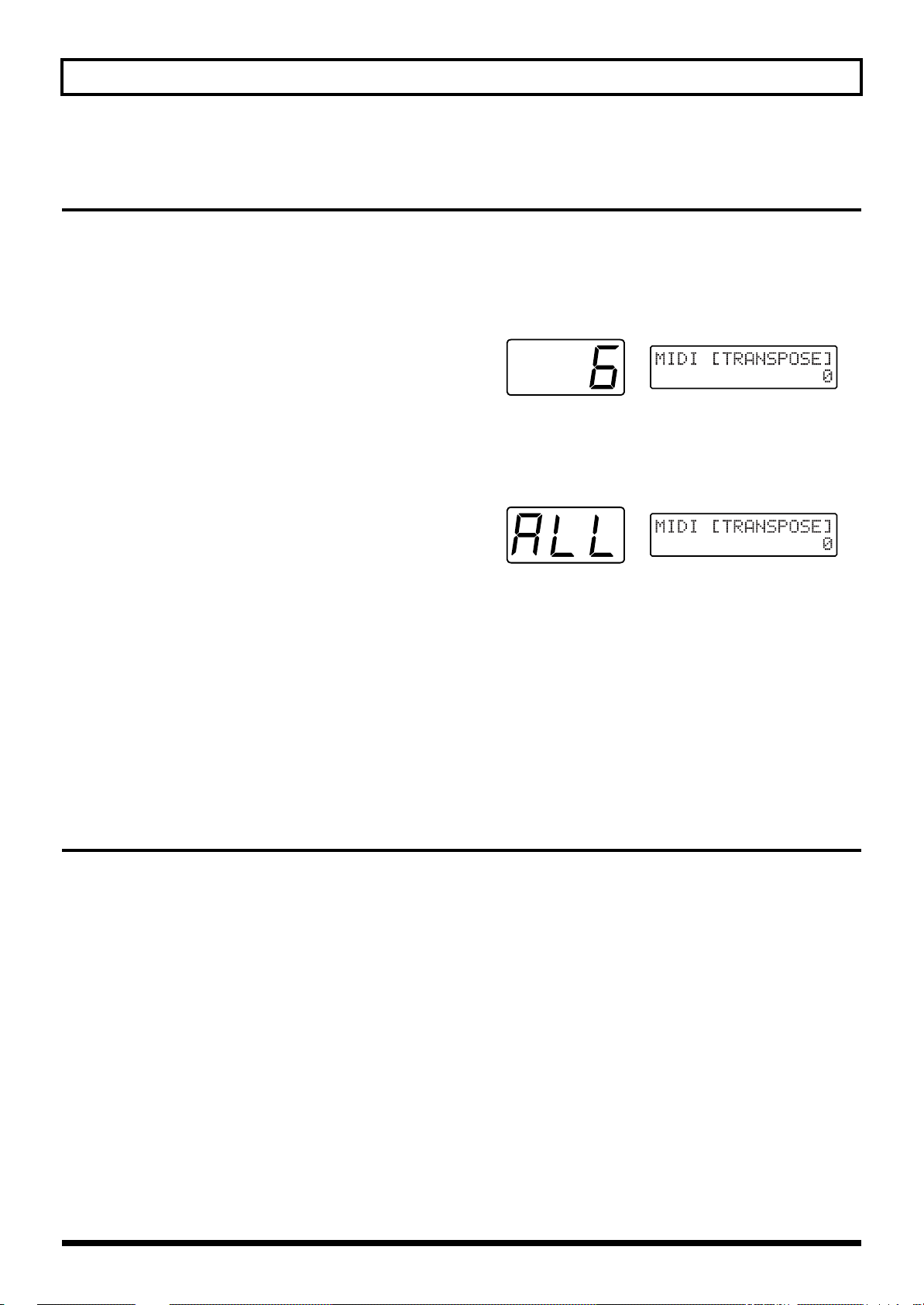
Chapter 9 Connecting to External Sound Generators and Sequencers
Transposing Performance Data for an External Sound Generator (MIDI [TRANSPOSE])
When using an external sound generator, notes in the bass
(or treble) range not on the guitar can be sent by changing the
COMMON setting “MIDI [TRANSPOSE]” in the Patch Edit
mode to transpose the output from MIDI OUT.
■ Procedure for Setting MIDI [TRANSPOSE]
1. Select the patch whose setting you want to change, and
press [COMMON] to enter Patch Edit mode.
2. Press [PARAMETER] to select “MIDI [TRANSPOE].”
fig.9-11
3. Press [STRING SELECT] to select “ALL.”
If you wish to change settings for individual strings,
refer to “Selecting different sounds for each string” (p.
89).
fig.9-12
4. Use [VALUE] to choose the value.
The available range that can be selected in “MIDI
[TRANSPOSE],” by semitone units, is -36 to +24.
5. Press [WRITE] to perform the Patch Write operation (p.
36).
* After performing the Patch Write operation, you will
automatically return to Play mode.
* If you don’t want to save the Patch, press [PLAY] to return to
Play mode.
What to do if an External Module Doesn’t Produce Sound as Expected
If the external sound generator doesn’t play as expected,
double-check the following items.
• Do the MIDI channels for sending and receiving match?
(p. 86)
• Make sure the volume level on the external sound
generator has not been lowered by sending a MIDI
Volume message been sent because of operation of
expression pedal volume.
• Make sure the volume on the GK-2A or the expression
pedal has not been turned down too low.
• Has the GK-2A select switch been set to “GUITAR”?
• Make sure that a sound generator which cannot
simultaneously receive six MIDI channels is receiving
data from the GR-33 in the Mono mode (p. 88).
92
* If the pitch sounds out of tune with the guitar, check “BEND
RANGE.” (p. 86)
* If “BEND RANGE” has been set to “0,” the pitch will change
in semitone.
* When transmitting in the Poly mode, pitch changes during
chord performances are in semitone (p. 86).
Page 93

Chapter 9 Connecting to External Sound Generators and Sequencers
Using the GR-33 as an External Sequencer Input Tool
By connecting the GR-33 to a MIDI sequencer (a performance-recording and playback device), even guitarists who don’t play
keyboards can perform real-time recording to the sequencer.
Connecting to a Sequencer
Use MIDI cables to hook up the GR-33, sequencer (or
computer running sequencer software) and multitimbral
sound generator as shown in the figure.
fig.9-13
MIDI IN
Multi timbral MIDI Sound Device
MIDI OUT
MIDI
IN
MIDI Sequencer
MIDI
OUT
Input Procedures and Settings for Each Device
1. Set the sending channel, sending mode, and bend
range on the GR-33 to match the sound generator being
used.
For details, refer to “Setting MIDI Channel/Bend Range
(CHANNEL, BEND RANGE)” (p. 86).
2. Turn on the Data Thru function (also called “Soft
Thru”) for MIDI IN → OUT on the sequencer. (Make
the setting so that MIDI message output from the GR33 during recording is also output through MIDI OUT
on the sequencer.)
3. Switch on the power to the GR-33 while holding down
the [PLAY] key to enable the “Local Control Off” state.
When doing this, the display reads “LOCAL
CONTROL OFF,” and then the unit starts.
For more detailed information about Local Control Off, see
the subsequent section, “About “Local Control Off.”
4. When everything is ready, play the guitar and make
sure the external sound generator produces sound. If
no problem is found, operate the external sequencer to
start recording. When the recording is done, put the
sequencer in the play mode and check what you’ve
recorded.
5. If you also wish to use the GR-33’s sound generator in
the song, also connect MIDI THRU on the external
sound generator to MIDI IN on the GR-33. This makes
it possible to use the GR-33 sound generator as well
while listening to the performance of the external MIDI
sound generator parts. (At this time, the sending MIDI
channel should be selected so as not to conflict with the
channel setting on the external sound generator.)
The setup just described can also be used to record tone
changes and effects from the built-in and external pedals in
addition to the sounds from the guitar performance. (While
using Harmonist, pressing the “Up” side of an external
BANK SHIFT pedal in the Pedal Effect mode toggles it
between a major and minor key, and this information is also
sent and recorded in the form of Control Change messages.)
* If you wish to record in a bass range that cannot be produced
by the guitar, change the “MIDI [TRANSPOSE]” setting to
“-12” (down one octave) or “-24” (down two octaves).
* If the sequencer you’re using doesn’t support simultaneous
recording on more than channel, use the Poly mode for
sending and recording (p. 88).
93
Chap.
9
Page 94

Chapter 9 Connecting to External Sound Generators and Sequencers
About “Local Control Off”
While the GR-33’s internal sound generator and guitar
controller are connected together, it is set to “Local On.” In
contrast to this, “Local Off” is when the GR-33’s internal
sound generator and guitar controller are separated, and
only MIDI message from a sequencer is played. Also, guitar
performance message is output only from MIDI OUT.
fig.9-14
Sequencer
Thru function to
MIDI OUT: On
GR-33
Generator
MIDI OUT
MIDI IN
Sound
Local Control
OFF
MIDI OUT
PITCH
TO MIDI
MIDI IN
GK IN
D
OW
S
N
Y
N
/
S
T
1
H
V
O
U
L
P
/
S
2
R
A
T
I
U
G
X
I
M
H
T
N
Y
S
Creating Realistic Plucked String Instrument Sounds (Data)
Using the GR-33 to input parts for guitars and similar string
instruments, including harps, koto, and others, makes it
possible to achieve voicing and an expressive feeling of
dispersions for separately plucked strings that cannot be
reproduced with keyboard input. When doing this, however,
attention should be given to the following points.
❍ Make sure that no Quantize function (a function which
forces data with loose input timing to conform to precise
timing as eighth notes, sixteenth notes, or the like) has
been enabled for input-data timing on the sequencer.
❍ When performing post-recording operation on the
sequencer to shift the position of data, make sure that
Bend messages are also shifted along with Note
messages, so as not to destroy the correspondences
between the two types of messages.
Also, those special changes in pitch that can only be
produced by a guitar synthesizer (such as using the tremolo
bar and harmonized bending) can also be input to the
sequencer and played by means of transmission in the Mono
mode, which uses one MIDI channel for each string.
Collisions of performance data from both the guitar and the
sequencer that occur at times such as when “soft thru” is
enabled can be prevented by turning off local control.
To turn off local control, switch the power off and back on
while holding down the [PLAY] button. (The setting for
turning off local control is canceled when the power is
switched on again, and is not saved in memory.)
* The detailed behavior of internal functions differs depending
on whether local control is on or off. Local control is normally
on, but you should be sure to switch off local control when a
loop connection with external equipment is used.
Making a MIDI loop connection with local control remaining
on may result in problems or faulty operation, such as failure
to recognize switch operations.
* Set MIDI [PC], MIDI [CC0], and MIDI [CC32] only when a
MIDI loop connection is not being used.
Recording Arpeggiator and Harmonist Performances
■
Recording Arpeggiator Effects on a Sequencer
Example 1:
Arpeggiate the notes of the external MIDI sound generator,
and record the results
Set the EFFECTS “HAR/ARP SELECT” setting in the Patch
Edit mode to “Arpeggio Ext,” then take the steps 1, 2 and 4 of
“Input Procedures and Settings for Each Device” on p. 93.
(Please don’t take step 3.) After taking step 4, play the guitar
and make sure that the external MIDI sound generator is
arpeggiated. Then, go to step 5 to record it.
Example 2:
Arpeggiate the GR-33’s first and second tones, and record the
results
Set the EFFECTS “HAR/ARP SELECT” setting in the Patch
Edit mode to “Arpeggio 1st,” “Arpeggio 2nd,” or “Arpeggio
1&2,” and carry out recording. (Arpeggios are played while
recording, but only the original guitar-performance
information—and not arpeggio information itself—is
recorded on the sequencer.) If the same patch is used during
playback, performance information is received from MIDI IN
and the GR-33 rebuilds the arpeggios.
* The setting “Arpeggio All” is not suitable for “HAR/ARP
SELECT” when a sequencer and the GR-33 are connected by a
MIDI cable (local control off).
94
Page 95

Chapter 9 Connecting to External Sound Generators and Sequencers
* As in Example 1 above, it is perfectly all right to record the
arpeggios themselves with “Arpeggio Ext,” then return this
data unchanged from MIDI OUT on the sequencer (to a patch
for which first and second tone arpeggios are off) to re-create
the arpeggios. However, this method cannot be used to recreate performance where both tones were played but only the
first tone was arpeggiated.
* When using transmission in the Poly mode (p. 88), only the
method described for Example 1 can be used to recording and
playback.
■
Recording Harmonist Effects on a Sequencer
Example 1:
Make the first tone the melody and the second tone the
harmony (or vice versa), and record the results
Set the EFFECTS “HAR/ARP SELECT” setting in the Patch
Edit mode to “Harmony 2nd” (or “Harmony 1st”), and while
in the same state as step 4 of “Input Procedures and Settings
for Each Device” on p. 93, play the guitar and make sure the
desired harmony is obtained. After that, continue from step 5
to record. The same harmony created when recording can be
reproduced by using the same patch during playback.
* The Harmony feature is not available for playback in Poly
mode. Use Mono mode.
Reducing the Size of a MIDI Pitch Bend Message
<The Bend Data Thin Function>
With the guitar, the finger vibrato technique can be used
to produce organic vibratos with amplitude and speed
that can be freely varied—something that’s very hard to
do with a keyboard.
When creating sequencer data, the GR-33 records such
finger vibratos, glissandos, and tremolo bar usage as
MIDI Pitch Bend messages. As a result of this, the MIDI
performance message that is output contains a large
number of Pitch Bend messages. In some cases, however,
these Pitch Bend messages can greatly inflate the amount
of data and exceed the sequencer’s memory capacity.
The Bend Data Thin function is available to keep this to a
minimum.
The amount of Pitch Bend messages that are sent can be
reduced by using the Bend Data Thin function. Although the
smoothness of pitch changes deteriorates, this can reduce the
amount of MIDI data.
Example 2:
Make the notes from the external MIDI sound generator the
melody and the first and second tones the harmony, and
record the results
Set the EFFECTS “HAR/ARP SELECT” setting in the Patch
Edit mode to “Harmony 1&2,” carry out recording in the
same way as for Example 1, and play back the performance
using the same patch. Make sure that the external sound
generator and the GR-33 are set to the same MIDI channel at
this time.
■ Calling Up the Bend Data Thin Function
1. Press [SYSTEM] to enter System mode.
2. Press [PARAMETER] to select “BEND DATA THIN.”
fig.9-15
3. Use [VALUE] to select “On.”
4. Press [PLAY] to return to Play mode.
* This is the setting items for the GR-33 (System mode), and not
patch settings, so there is no need to perform a Patch Write
operation. The latest setting is automatically stored in
memory, even after the power is switched off.
This results in a reduced amount of pitch bend data
transmissions until BEND DATA THIN is set to “Off” again.
(While this function is active, the smoothness of pitch
changes for the internal sound generator is also restricted.)
Chap.
9
95
Page 96

Chapter 9 Connecting to External Sound Generators and Sequencers
Practical Use of MIDI Channels
fig.9-16
Transmitting in Mono Mode
Guitar 1
Mono Mode ch1 Mono Mode ch7
MIDIch
1
2345678910111213141516
In use
Transmitting in Poly Mode
Poly Mode ch1
MIDIch
1
2345678910111213141516
In use
Guitar 1
Poly Mode ch2
14 channels remaining available for use
Guitar 2
Only 4 channels
remaining available for use
Guitar 2
A single MIDI system has 16 channels, and ordinarily 16
instrument parts can exist.With a guitar synthesizer,
however, each of the six strings takes up one channel.
This means that, for instance, two-part input with the guitar
synth to an ensemble from a 16-part external multitimbral
sound generator would use up 12 channels.
In cases like this, set the System mode setting “BASIC
CHANNEL” (p. 86) to “Poly 1” to “Poly 16” and send input
to the sequencer with Poly mode sending. This lets you
proceed with recording while using up only one channel per
part, as with a keyboard instrument.
One drawback of transmitting in Poly mode is that it is not
possible to send Pitch Bend messages for bending, sliding,
vibratos, and the like when playing chords, but this mode
can help in economical use of channels and parts when used
judiciously separately from Mono mode input while giving
consideration to the tones to be used and to single-note
playing.
What to do When You Have Difficulty Sequencing
❍ Double-check the MIDI cable connections (OUT → IN, p.
93) and the setting for local control (on or off—p. 94).
❍ When performing playback, be sure to check the MIDI
channel and Bend Range settings (p. 86).
❍ Be sure that the transmitting modes (Mono or Poly)
match up. If only the sound for one string is heard
during playback, you may be sending performance data
to created with transmission in Mono mode a nonmultitimbral sound generator.
❍ If MIDI cannot be sent and recording is impossible for
only a particular string, use the [STRING SELECT]
button to set the COMMON “MIDI [PC]” setting in the
Patch Edit mode to the string’s number, and make sure
that the setting is not “Off.” (p. 88)
❍ During transmission in Poly mode, pitch changes for
chord play are in semitone steps. If continuous change in
pitch is needed, use single-note playing or transmission
in MIDI Mono mode.
❍ If MIDI Bend Range is set to “1” or “2,” unpleasant
retriggering of sounds may occur frequently during a
performance with continuous changes in pitch through
bending or the like. When using the same Bend Range
setting for both sending and receiving, make the value as
large as possible. (p. 86)
❍ To achieve faster sound generation and smooth pitch
changes, the GR-33 transmits pitch as a combination of
Note messages and Pitch bend messages. This means
that if the sequencer’s microscope (event list) screen
shows only Note messages, what appears on-screen may
differ from what is actually performed. If continuous
pitch change is not required, you can create data that is
displayed more faithfully by setting the sending Bend
Range to “0” (p. 86).
96
Page 97

Chapter 10 Other Convenient Functions
Re-assigning Program Change Numbers in the Order of Patches
If you have repeatedly changed the original settings of
patches and re-written them to different memory locations,
or have otherwise reordered the patches, the Program
Change numbers “(MIDI [PC])” assigned to the patches no
longer correspond to their actual order.
If you want the fixed reception program change numbers to
once again correspond to the patch numbers starting at the
first patch, use the following procedure to reassign the
transmission program change numbers (to the factory
settings) starting at the first patch.
* Please note that performing this operation causes all prior
“MIDI [PC]” settings for the patches to be lost.
■ Re-assigning Program Change Numbers in
the Order of Patches
1. Press [SYSTEM] to enter System mode.
2. Press [PARAMETER] to select “FACTORY RESET.”
fig.10-01
3. Turn [VALUE] to select “PC Number.”
4. Press [WRITE].
The message “Sure ?” appears, asking you to confirm
that you want to perform the Factory Reset operation.
fig.10-02
5. To perform the operation, press [WRITE] again.
“Now Writing...” appears in the display. In a moment,
the GR-33 automatically returns to Play mode,
completing the factory Reset.
The patches’ Program Change numbers are re-assigned
in sequence starting from the first patch (1, 2, 3,..., 127,
128). (All Control Change No. 0 (MIDI[CC0]) and No. 32
(MIDI[CC32]) values are returned to “0” for the sending
of Bank Select messages for user patches.)
To cancel the operation, press any button other than
[WRITE].
Terminating Transmission of the MIDI Controller No. 7 (Volume)
Control Change No. 7 is used not only for sending changes
from the GK-2A’s volume knob, but also for sending data
from its “SYNTH - MIX - GUITAR” selector switch. You may
occasionally encounter a MIDI-capable effects processor that
cannot be set to ignore Control Change No. 7 volume control
messages.
If this occurs, it will require your attention, because when the
GR-33 has been connected via MIDI cables to an external
effects processor—for the processing of guitar sounds and
fig.10-03
To guitar amp
Effects processor for guitar sound
unable to stop receiving Volume
messages.
To synth-sound amp
* Patch Change messages are sent
from the GR-33 to the guitar
effects processor.
MIDI control of the external effects—setting the selector
switch on the GK-2A to “GUITAR” may mute the guitar
sound, not just the synth sound.
When using the GR-33 in combination with a processor that
cannot block out Control Change No. 7 messages, follow the
steps below to prevent the GR-33 from sending this type of
data.
D
O
W
N
/
S
1
U
P
/
S
2
S
Y
N
T
H
V
O
G
L
U
M
I
T
I
X
S
A
Y
R
N
T
MIDIIN*
H
Chap.
10
97
Page 98

Chapter 10 Other Convenient Functions
■ Terminating Transmission of the MIDI
Controller No. 7
1. Press [SYSTEM] to enter System mode.
2. Press [PARAMETER] to select “VOL SEND SW.”
fig.10-04
3. Turn [VALUE] to select “Off.”
4. Press [PLAY] to return to Play mode.
* This is a system-wide setting, and not a patch setting, so there
is no need to perform a patch write operation. The setting is
automatically stored in memory even after the power is
switched off.
This stops the transmission of Control Change No. 7 from
MIDI OUT, eliminating the problem described above.
* This also terminates transmission of Control Change No. 7
messages for other volume-related control, so this setting
should not used except when necessary. Please note that once
transmission has been disabled, it remains so until you switch
the setting back to “On” or restore system-related settings to
their default values by performing a Factory Reset (p. 16).
Terminating Transmission of the Bend Range Request Message
The GR-33 informs any external MIDI device of the GR-33’s
current Bend Range setting each time a new patch is selected.
The messages used here are MIDI RPN (Registered
Parameter Number) “Pitch Bend Sensitivity” messages—that
is, Control Change messages No. 100, No. 101, No. 6, and No.
38.
If it is necessary for some reason to stop the transmission of
these messages—such as when you wish to reduce the
number of messages sent to a sequencer as you change
patches on the GR-33—follow the steps below to turn off this
function.
1. Press [SYSTEM] to enter System mode.
2. Press [PARAMETER] to select “BEND REQ SW.”
fig.10-05
3. Turn [VALUE] to select “Off.”
4. Press [PLAY] to return to Play mode.
* This is a system-wide setting, and not a patch setting, so there
is no need to perform a Patch Write operation. The setting is
automatically stored in memory, even after the power is
switched off.
Once you’ve done this, no Bend Range Request messages
(MIDI Pitch Bend Sensitivity) are sent when changing
patches.
* Please note that once transmission has been disabled, it
remains so until you return the setting to “On” or restore
system-related settings to their default values by performing a
Factory Reset (p. 16).
98
Page 99

Chapter 11 Appendices
Troubleshooting
During Normal Play with Just the GR-33
No synth sounds are heard when the
guitar is played
● If the unit’s volume knob turned down too low?
→ Adjust the volume to an appropriate level.
● Is the volume on the GK-2A turned down too low? Is
the GK-2A’s selector switch set to GUITAR?
→ Set the switch to SYNTH or MIX, and adjust the volume
to an appropriate level.
● Has the expression pedal assigned with the Volume
function been returned to its raised position?
→ Depress the expression pedal.
● Has neither the first nor second tone been selected for
the Layer setting?
→ Assign the first (or second) tone to each of the strings (p.
51).
● Is the “PATCH LEVEL” setting too low?
→ Adjust the volume to an appropriate level (p. 38).
The volume fluctuates from one string
to another
● Are the “PICKUP SENS” settings correct for each
string?
→ Adjust the settings as required (p. 17).
Pitch doesn’t rise when using Pitch Glide
(or the expression pedal Pitch function)
● Functions that vary pitch continuously may experience
a limited range of change during rising pitch due to the
tone or register.
→ If a limitation is encountered, use with a narrower width
of change (p. 44).
The sound change produced by an
expression pedal varies from one tone
to another
● For some of the 384 tones, the way the effect is applied
varies subtly from the usual case when the Brightness
or Wah-Wah function is assigned.
→ Actually assign the function and check in advance how
the effect is applied (p. 47).
The pitch stays the same even when
the Master Tune setting is changed.
● The only sounds that immediately change in pitch
when the GR-33’s Master Tune setting is changed are
synth sounds controlled by an external MIDI
instrument. Except when the patch “CHROMATIC”
setting is set to a value from “Type1” to “Type3,” synth
sounds controlled by the guitar follow the guitar’s
actual pitch, regardless of the Master Tune setting.
→ After making the Master Tune setting (p. 18), use the
built-in tuner to retune the guitar (p. 18) and ensure that
all pitches (including the guitar) are in tune.
The Layer setting is correct, but one
tone is not heard
● Is “1:2 BALANCE” (p. 52) set too much to the first tone
or the second tone?
→ Adjust the setting to obtain a suitable balance.
● Has the expression pedal assigned with tone balance
been depressed (or returned to its raised position)?
→ Try operating the expression pedal.
The way modulation is applied varies
from one tone to another when using
the unit’s pedal effect or expression
pedals
● Each tone has an independent setting for the speed of
undulations in pitch when using modulation.
→ Check the undulations in advance and choose a tone
with an undulation speed that matches the song.
● The “Modulation” setting for the pedal effect (WAH)
also has an independent setting in effect (undulation)
depth for each tone.
→ Check the depth of the effect choose a tone with a depth
that matches the song.
One tone is not heard when the
expression pedal is used to change
the tone’s volume balance
● Is the TONE “LAYER” setting set so that only the first
or the second tone (but not both) is played?
→ Change the setting so that the first and second tones are
both played (p. 51).
Chap.
11
99
Page 100

Chapter 11 Appendices
● Is the TONE “1:2 BALANCE” setting (p. 52) set to “50”
or “-50”?
→ Change the setting to a value closer to “0” and check
operation.
The built-in effects don’t work
● Is the EFFECTS setting item “REV SEND LEVEL” (p.
75), “CHO SEND LEVEL” (p. 74) set to “0,” or “MULTIFX SW” (p. 53) set to “Off”?
→ Select a type other than “Off.”
● Are the “REV SEND LEVEL,” “CHO SEND LEVEL,”
and volume-related Multi-effect parameters set to
appropriate values?
→ Set them to appropriate values.
● Is the three-digit display blinking “Edt” to indicate
that the unit is in EFFECT BYPASS mode?
→ Press [EFFECTS] to release the Bypass function (p. 75).
● The GR-33’s built-in effects are exclusively for use
with the internal synth sounds. They are not applied to
the sounds of the guitar itself.
→ You can apply external effects for the guitar to only the
guitar sounds by using the GUITAR OUT jack. (If you
wish to use a single amp for both the guitar and synth
sounds, you should also use the GUITAR RETURN jack
as well.) (p. 15)
● If the “Cho Send Level (Chorus Send Level)” or “Rev
Send Level (Reverb Send Level)” function is selected,
make sure that the expression pedal (p. 47) is not
rocked back all the way.
→ Depress the expression pedal.
The pitch of the synth sounds doesn’t
change in the same way as the pitch
of the guitar sounds
● Some tones (such as percussion instruments and effect
sounds) show different changes in pitch than with the
guitar. This is not a defect.
Pitch doesn’t change smoothly
● Is COMMON “CHROMATIC” set to a value from
“Type1” to “Type3”?
→ Set CHROMATIC to “Off” for patches that require
continuous changes in pitch (p. 42).
● Is the Bend Data Thin function (p. 95) in use? Using
this function may result in a slight loss of smoothness
when pitch changes, even during normal play.
→ Do not use the Bend Data Thin function when it is not
needed.
“Battery Low!” appears in the display
when the power is switched on
● This is a warning that means that the internal battery
which maintains user patch and system setting data is
almost dead. If this message appears, data may be lost
is the battery is not replaced quickly.
→ Contact servicing by your dealer or qualified Roland
service personnel.
When Changing Patch Settings
The display suddenly starts flashing
● In a parameter where the [STRING SELECT] button is
valid and you select “ALL” (all strings) or “5-6” (strings
5 and 6), the blinking display indicates that the current
settings differ between strings.
● During EFFECTS editing, a blinking “Edt” indicates
that the bypass function is ON.
The sound doesn’t vary when the
settings are changed
● the GR-33’s Attack, Release, and Brightness settings
are intended to adjust the original data belonging to
each tone. This means that the range of change differs
according to the tone, and some tones may not show
much of a change.
● If Harmonist is on, scale changes for synth sounds are
different from the guitar when “HAR/ARP SELECT”
(p. 82) is set to “Harmony All” or “Harmony 1&2.”
Noise with subtle undulations is hear
in extremely high registers
● This is a phenomenon peculiar to digital sound
generators known as “aliasing noise.” It may be
audible when using the slide technique or the Pitch
Shift function, but it is not a defect. The GR-33 is
designed to minimize such noise during guitar play.
100
● Is the setting being changed one of the seven settings
that can be made independently for each string (see the
following item), and is the setting affecting only a
particular string?
→ Use the [STRING SELECT] button to set it to “ALL.” (p.
35)
 Loading...