


Contents
Studio Set ..........................................5
STUDIO SET COMMON .................................. 5
General tab ........................................ 5
Control tab ........................................5
Phase Lock tab ....................................5
Pedal tab ..........................................6
S1/S2 tab .......................................... 6
Knob tab .......................................... 6
D-Beam tab .......................................7
Control Sw tab ..................................... 8
PART VIEW .............................................. 9
Level/Pan tab ...................................... 9
Keyboard tab ...................................... 9
Output/EFX tab ...................................10
EQ tab ............................................10
Pitch tab .........................................11
Scale Tune tab ....................................11
Vibrato tab .......................................12
Oset tab ........................................12
Mono/Poly/Legato tab ............................13
Voice Reserve tab .................................13
MIDI Rx Filter tab .................................13
EFFECTS EDIT .....................................14
STUDIO SET EFFECTS ...................................15
Chorus tab .......................................15
Reverb tab .......................................15
Comp+EQ Output tab ............................16
Master Comp tab .................................16
IFX tab ...........................................16
TONE EFFECTS (MFX, COMP+EQ) .......................17
SYSTEM EFFECTS .......................................18
Audio Input tab ...................................18
USB Audio tab ....................................18
Noise Suppressor tab .............................18
MIC Reverb tab ...................................18
Master EQ tab ....................................19
TFX tab ...........................................19
TFX Parameters .......................................20
FILTER+DRIVE .....................................20
ISOLATOR ........................................20
DJFX LOOPER .....................................20
BPM LOOPER .....................................20
BIT CRUSH ........................................20
WAH .............................................20
REVERB ...........................................20
DELAY ............................................20
TAPE ECHO .......................................20
PITCH SHIFTER ....................................21
VOICE TRANS .....................................21
FLANGER .........................................21
SLICER+FLG ......................................21
PHASER ..........................................21
CHORUS ..........................................21
2
TREMOLO/PAN ...................................21
OVERDRIVE .......................................21
DISTORTION ......................................21
FUZZ .............................................21
OCTAVE ..........................................22
SUBSONIC ........................................22
RING MOD ........................................22
CHROMATIC PS ...................................22
C. CANCELLER ....................................22
VINYL SIM ........................................22
RADIO TUNING ...................................22
NOISE GEN .......................................22
COMP ............................................22
EQUALIZER .......................................22
SuperNATURAL Acoustic Tone (SN-A) ...............24
TONE EDIT (SN-A) ......................................24
Common tab .....................................24
Inst tab ...........................................25
Instrument List .......................................25
SuperNATURAL Inst Parameters .......................26
Performance Variation Sounds ........................29
MFX tab ..........................................30
MFX Control tab ..................................30
SuperNATURAL Synth Tone (SN-S) ..................31
TONE EDIT (SN-S) ......................................31
Common tab .....................................31
OSC tab ..........................................33
Pitch tab .........................................33
Filter tab .........................................34
Amp tab ..........................................35
LFO tab. . . . . . . . . . . . . . . . . . . . . . . . . . . . . . . . . . . . . . . . . . . 35
Modulation LFO tab ..............................36
Aftertouch tab ....................................36
Misc tab ..........................................36
MFX tab ..........................................37
MFX Control tab ..................................37
SuperNATURAL Drum Kit (SN-D) ....................38
TONE EDIT (SN-D) ......................................38
Common tab .....................................38
DRUM Inst tab ....................................38
Comp tab ........................................39
EQ tab ............................................39
MFX tab ..........................................39
MFX Control tab ..................................39
SuperNATURAL Drum Inst List ..........................40
PCM Synth Tone (PCMS) ...........................42
TONE EDIT (PCMS) .....................................42
Common tab .....................................42
Wave tab .........................................45
PMT tab ..........................................47
Pitch tab .........................................49

Contents
Pitch Env tab .....................................50
TVF tab ...........................................51
TVF Env tab .......................................52
TVA tab. . . . . . . . . . . . . . . . . . . . . . . . . . . . . . . . . . . . . . . . . . . 53
TVA Env tab ......................................54
Output tab .......................................55
LFO1/LFO2 tab ...................................55
Step LFO tab. . . . . . . . . . . . . . . . . . . . . . . . . . . . . . . . . . . . . . 57
How to Apply the LFO ............................57
Control tab .......................................58
Matrix Control 1–4 tab ............................58
MFX tab ..........................................60
MFX Control tab ..................................60
PCM Drum Kit (PCMD) .............................61
TONE EDIT (PCMD) .....................................61
Common tab .....................................61
Wave tab .........................................62
WMT tab .........................................63
Pitch tab .........................................63
Pitch Env tab .....................................63
TVF tab ...........................................64
TVF Env tab .......................................65
TVA tab. . . . . . . . . . . . . . . . . . . . . . . . . . . . . . . . . . . . . . . . . . . 65
TVA Env tab ......................................66
Output tab .......................................66
Comp tab ........................................66
EQ tab ............................................67
MFX tab ..........................................67
MFX Control tab ..................................67
Chorus, Reverb ....................................68
Chorus Parameters .....................................68
Reverb Parameters .....................................68
IFX Parameters ....................................69
Equalizer .........................................70
Spectrum .........................................70
Isolator ...........................................70
Low Boost ........................................70
Super Filter .......................................71
Step Filter ........................................71
Enhancer .........................................71
Auto Wah .........................................72
Humanizer .......................................72
Speaker Simulator ................................72
Phaser ............................................73
Step Phaser .......................................73
Multi Stage Phaser ................................73
Innite Phaser ....................................73
Ring Modulator ...................................74
Step Ring Modulator ..............................74
Tremolo ..........................................74
Auto Pan .........................................74
Step Pan ..........................................75
Slicer .............................................75
Rotary ............................................75
VK Rotary .........................................76
Chorus ...........................................76
Flanger ...........................................76
Step Flanger ......................................77
Hexa-Chorus .....................................77
Tremolo Chorus ..................................77
Space-D ..........................................77
3D Chorus ........................................78
3D Flanger .......................................78
3D Step Flanger ..................................78
2 Band Chorus ....................................79
2 Band Flanger ...................................79
2 Band Step Flanger ..............................79
Overdrive ........................................80
Distortion ........................................80
VS Overdrive .....................................80
VS Distortion .....................................80
Guitar Amp Simulator .............................80
Compressor ......................................81
Limiter ...........................................81
Gate ..............................................81
Delay .............................................81
Long Delay .......................................82
Serial Delay .......................................82
Modulation Delay .................................82
3Tap Pan Delay ...................................83
4Tap Pan Delay ...................................83
Multi Tap Delay ...................................83
Reverse Delay ....................................84
Shue Delay .....................................84
3D Delay .........................................84
Time Ctrl Delay ...................................85
Long Time Ctrl Delay ..............................85
Tape Echo ........................................85
Lo Noise. . . . . . . . . . . . . . . . . . . . . . . . . . . . . . . . . . . . . . . . . 86
Lo Compress ....................................86
Lo Radio ........................................86
Telephone ........................................87
Phonograph ......................................87
Pitch Shifter ......................................87
2Voice Pitch Shifter ...............................87
Step Pitch Shifter .................................88
Reverb ...........................................88
Gated Reverb .....................................88
Overdrive g Chorus ..............................89
Overdrive
Overdrive g Delay ................................89
Distortion g Chorus ..............................89
Distortion g Flanger ..............................89
Distortion g Delay ...............................90
Enhancer g Chorus ...............................90
Enhancer g Flanger ..............................90
g Flanger ..............................89
3

Contents
Enhancer g Delay ................................90
Chorus g Delay ..................................90
Flanger g Delay ..................................91
Chorus g Flanger .................................91
Sympathetic Resonance ..........................91
When Using 3D Eects ................................92
MFX Parameters ...................................93
Equalizer .........................................94
Spectrum .........................................94
Low Boost ........................................94
Step Filter ........................................94
Enhancer .........................................95
Auto Wah .........................................95
Humanizer .......................................95
Speaker Simulator ................................95
Phaser 1 ..........................................96
Phaser 2 ..........................................96
Phaser 3 ..........................................96
Step Phaser .......................................97
Multi Stage Phaser ................................97
Innite Phaser ....................................97
Ring Modulator ...................................98
Tremolo ..........................................98
Auto Pan .........................................98
Slicer .............................................98
Rotary 1 ..........................................99
Rotary 2 ..........................................99
Rotary 3 .........................................100
Chorus ..........................................100
Flanger ..........................................101
Step Flanger .....................................101
Hexa-Chorus ....................................102
Tremolo Chorus .................................102
Space-D .........................................102
Overdrive .......................................102
Distortion .......................................102
Guitar Amp Simulator ............................103
Compressor .....................................103
Limiter ..........................................103
Gate .............................................104
Delay ............................................104
Modulation Delay ................................105
3Tap Pan Delay ..................................105
4Tap Pan Delay ..................................105
Multi Tap Delay ..................................106
Reverse Delay ...................................106
Time Ctrl Delay ..................................107
LOFI Compress ..................................107
Bit Crusher ......................................107
Pitch Shifter .....................................107
2Voice Pitch Shifter ..............................108
Overdrive g Chorus .............................108
Overdrive g Flanger .............................108
4
Overdrive g Delay ...............................109
Distortion g Chorus .............................109
Distortion g Flanger .............................109
Distortion g Delay ..............................109
OD/DS g TouchWah .............................109
OD/DS g AutoWah ..............................110
GuitarAmpSim g Chorus ........................110
GuitarAmpSim g Flanger ........................111
GuitarAmpSim g Phaser .........................111
GuitarAmpSim g Delay .........................112
EP AmpSim g Tremolo ..........................113
EP AmpSim g Chorus ............................113
EP AmpSim g Flanger ...........................113
EP AmpSim g Phaser ............................114
EP AmpSim g Delay .............................114
Enhancer g Chorus ..............................115
Enhancer g Flanger .............................115
Enhancer g Delay ...............................115
Chorus g Delay .................................115
Flanger g Delay .................................116
Chorus g Flanger ................................116
Vocoder .........................................116
About the STEP RESET Function ......................117
Controlling a MFX via MIDI (MFX CONTROL) ..........117
SuperNATURAL Tone CC Assign ...................118
SuperNATURAL Acoustic (SN-A) .......................118
SuperNATURAL Drum (SN-D) ..........................120
Copyright © 2017 ROLAND CORPORATION

Studio Set
STUDIO SET COMMON
1. Press the [MENU] button.
2. Move the cursor to “Studio Set Common” and press the [ENTER] button.
The STUDIO SET COMMON screen appears.
Parameter Value Explanation
General tab
This species the play mode.
SINGLE Single play
Keyboard Mode
Pad Part Select Part1–Part16, OFF Species the pad part (the part that records performance data from the pads).
Drum Comp+EQ Assign Part1–Part16
SPLIT Split play
DUAL Dual play
STUDIO SET Multi part play
Species the part that will use the six sets of compressor + equalizer that are provided for use with
a drum kit.
* If a tone (not a drum kit) is assigned to the part specied by Drum Comp+EQ Assign, the
Comp+EQ will not be available.
Control tab
Control Source Select (System) SYSTEM, STUDIO SET
OFF,
Tone Control Src1–4
CC01–CC31,
CC33–CC95,
PICTH BEND, AFTERTOUCH
Phase Lock tab
Phase Lock (Ch1)–Phase Lock
(Ch16)
OFF, ON
SYSTEM: The Control Source Select system parameters System Control 1–4 Source are used for
tone control.
STUDIO SET: Tone Control Src1–4 are used for tone control.
* Control Source Select (System) settings are system parameters.
* If you choose “SYSTEM,” the settings of the studio set parameters Tone Control Src1–4 are
ignored.
Specify the MIDI messages that will be used for Tone Control of the studio set.
Set Phase Lock to “ON” when you want to suppress discrepancies in timing of parts played on the
same MIDI channel.
When the Phase Lock parameter is set to “ON,” parts on the same MIDI channel are put in
a condition in which their timing is matched, enabling them to be played at the same time.
Accordingly, a certain amount of time may elapse between reception of the Note messages and
playing of the sounds. Turn this setting to “ON” only as needed.
* Phase Lock is not available for SuperNATURAL acoustic organ-type instruments.
5

Studio Set
Parameter Value Explanation
Pedal tab
Species whether the functions controlled by the pedals connected to the FOOT PEDAL CTRL
1 and 2 jacks will be determined by the system settings (SYSTEM) or by the studio set settings
Pedal Assign Source (System) SYSTEM, STUDIO
Specify the functions that are controlled by pedals connected to the FOOT PEDAL CTRL 1 and 2 jacks.
OFF No function is assigned.
Pedal 1 Assign
Pedal 2 Assign
CC01–31, 32 (OFF), 33–95 Controller number 1–31, 32, 33–95
BEND DOWN The same eect as moving the pitch bend lever to the left.
BEND UP The same eect as moving the pitch bend lever to the right.
AFTERTOUCH Aftertouch
(STUDIO).
* Pedal Assign Source (System) is a system parameter.
* If you choose “SYSTEM,” the settings of the studio set parameters Pedal 1/2 Assign are ignored.
S1/S2 tab
Species whether the functions controlled by the [S1] [S2] buttons will be determined by the
system settings (SYSTEM) or by the studio set settings (STUDIO).
S1/S2 Assign Source (System) SYSTEM, STUDIO
Assignable
Specify the functions that are controlled by the [S1] [S2] buttons.
Some of the SuperNATURAL acoustic tones let you use control changes to modify the character of the sound or switch to other variation
sounds. For details, refer to “SuperNATURAL Tone CC Assign” (p. 118).
*1: The Switch S1/2 Assign setting is xed at “LATCH.”
OFF No function is assigned.
CC01–31, 32 (OFF), 33–95
Switch S1 Assign
Switch S2 Assign
Switch S1 Mode
Switch S2 Mode
AFTERTOUCH Aftertouch
MONO/POLY Switch between mono/poly.
CHORUS SWITCH *1 Turn the chorus on/o.
REVERB SWITCH *1 Turn the reverb on/o.
MASTER EQ SWITCH *1 Turn the master EQ on/o.
TFX SWITCH *1 Turn the total eect on/o.
MASTER KEY DOWN *1 Lower the keyboard range by a semitone.
MASTER KEY UP *1 Raise the keyboard range by a semitone.
LATCH The setting is turned on/o each time you press the button.
MOMENTARY
* S1/S2 Assign Source (System) is a system parameter.
* If you choose “SYSTEM,” the settings of the studio set parameters Switch S1/S2 Assign and
Switch S1/S2 Assign Mode are ignored.
Controller number 1–31, 32, 33–95
CC16 (General-1)–CC19 (General-4) and CC80 (General-5)–CC83 (General-8) apply specic eects if
a SuperNATURAL acoustic tone is selected (p. 118).
The setting is turned on while you hold down the button, and turned o when you release the
button.
Knob tab
Knob Assign Source (System) SYSTEM, STUDIO
Specify the functions that are controlled by the SOUND MODIFY knobs.
OFF No function is assigned.
Sound Modify Knob 1–6 Assign
6
CC01–31, 32 (OFF), 33–95
PITCH BEND Applies the same eect as when the pitch bend lever is moved.
AFTERTOUCH Aftertouch
TFX PARAM 1–3 Controls parameters 1–3 of the Total Eect.
Species whether the functions controlled by the SOUND MODIFY knobs will be determined by
the system settings (SYSTEM) or by the studio set settings (STUDIO).
* Knob Assign Source (System) is a system parameter.
* If you choose “SYSTEM,” the settings of the studio set parameters Sound Modify Knob 1–6
Assign are ignored.
Controller number 1–31, 32, 33–95
CC16 (General-1)–CC19 (General-4) and CC80 (General-5)–CC83 (General-8) apply specic eects if
a SuperNATURAL acoustic tone is selected (p. 118).

Studio Set
Parameter Value Explanation
D-Beam tab
Species whether the functions controlled by the D-BEAM controller will be determined by the
system settings (SYSTEM) or by the studio set settings (STUDIO).
D-Beam Assign Source (System) SYSTEM, STUDIO
Specify the functions that are controlled by the D-BEAM controller.
OFF No function is assigned.
D-Beam Switch
Solo Synth (System)
* The various Solo Synth (System) parameters are system parameters.
Level 0–127 Adjusts the volume of the solo synth.
Chorus Send Level 0–127 Adjusts the chorus send level.
Reverb Send Level 0–127 Adjusts the reverb send level.
Range 2–8OCT Adjusts the range in which the pitch of the solo synth will vary.
Osc 1 Waveform SAW, SQR
Osc 1 Pulse Width 0–127
Osc 1 Coarse Tune -48–+48 Adjusts the pitch of the tone’s sound (in semitones, +/-4 octaves).
Osc 1 Fine Tune -50–+50 Adjusts the pitch of the tone’s sound (in 1-cent steps).
Osc 2 Waveform
Osc 2 Pulse Width
Osc 2 Coarse Tune
Osc 2 Fine Tune
Osc 2 Level 0–127 Adjusts the level of the Osc 2.
Osc Sync Switch OFF, ON
Filter Type
Cuto 0–127 Frequency at which the lter begins to have an eect on the waveform’s frequency components.
Resonance 0–127
LFO Rate 0–127 Adjusts the modulation speed of the LFO.
LFO Osc 1 Pitch Depth -63–+63 Species the depth to which the LFO will modulate the Osc 1 pitch.
LFO Osc 2 Pitch Depth -63–+63 Species the depth to which the LFO will modulate the Osc 2 pitch.
LFO Osc 1 Pulse Width Depth -63–+63
LFO Osc 2 Pulse Width Depth -63–+63
Assignable
SOLO SYNTH The D-BEAM controller operates as a monophonic synthesizer.
EXPRESSION The D-BEAM controller controls the volume.
ASSIGNABLE The D-BEAM controller controls the function that you assign.
(same as Osc 1)
Species the type of lter.
OFF No lter is used.
LPF (Low Pass Filter) This reduces the volume of all frequencies above the cuto frequency (Cuto).
BPF (Band Pass Filter) This leaves only the frequencies in the region of the cuto frequency, and cuts the rest.
HPF (High Pass Filter) This cuts the frequencies in the region below the cuto frequency.
PKG (Peaking Filter) This emphasizes the frequencies in the region of the cuto frequency.
Species the function that is assigned to the D-Beam Switch “ASSIGNABLE” setting.
* D-Beam Assign Source (System) is a system parameter.
* If you choose “SYSTEM,” the settings of the studio set parameters D-Beam Switch and
Assignable are ignored.
Selects the waveform.
SAW (sawtooth wave), SQR (square wave)
Species the pulse width of the waveform.
By cyclically modifying the pulse width you can create subtle changes in the tone.
Turning this switch on produces a complex sound with many harmonics. This is eective when the
Osc 1 pitch is higher than the Osc 2 pitch.
Emphasizes the portion of the sound in the region of the cuto frequency, adding character to the
sound.
Species the depth to which the LFO will modulate the pulse width of the Osc 1 waveform.
* The Pulse Width is activated when “SQR” is selected with Osc 1 waveform.
Species the depth to which the LFO will modulate the pulse width of the Osc 2 waveform.
* The Pulse Width is activated when “SQR” is selected with Osc 2 waveform.
D-Beam Assign
MEMO
You can use the SOUND MODIFY knobs to control the “CUTOFF”–”TFX CTRL” parameters. You can also use the D-BEAM controller to
control the same parameters.
OFF No function is assigned.
CC01–31, 32 (OFF), 33–95
BEND DOWN The same eect as moving the pitch bend lever to the left.
BEND UP The same eect as moving the pitch bend lever to the right.
AFTERTOUCH Aftertouch
Controller number 1–31, 32, 33–95
CC16 (General-1)–CC19 (General-4) and CC80 (General-5)–CC83 (General-8) apply specic eects if
a SuperNATURAL acoustic tone is selected (p. 118).
7

Studio Set
Parameter Value Explanation
CUTOFF Adjusts the cuto frequency.
RESONANCE Adjusts the resonance.
ATTACK Adjusts the attack.
RELEASE Adjusts the release.
PAN Adjusts the pan.
LEVEL Adjusts the volume.
EQ LOW Adjusts the low frequency range.
EQ MID1 Adjusts the mid-1 frequency range.
EQ MID2 Adjusts the mid-2 frequency range.
D-Beam Assign
Range Max 0–127
Range Min 0–127
Beam Assign Knob Polarity STANDARD, REVERSE
Beam Assign Sample Pad Number
EQ MID3 Adjusts the mid-3 frequency range.
EQ HIGH Adjusts the high frequency range.
INPUT LEVEL Adjusts the input volume from the AUDIO INPUT jack.
KNOB ASSIGN1–6 Adjust the [1] (ASSIGN 1)–[6] (ASSIGN 6) knobs.
COMPRESSOR Adjusts the compressor.
TONE Adjusts the tone.
CHORUS Adjusts the chorus.
REVERB Adjusts the reverb.
TFX SELECT Selects the total eect.
TFX CTRL Controls the total eect.
SAMPLE PAD Plays a sample.
Species the upper limit of the D-BEAM controller range.
* This is shown only if D-Beam Assign is set to “C C,” “BEND DOWN,” “BEND UP,” or
“AFTERTOUCH.”
MEMO
By setting the Range Max below the Range Min, you can invert the range of variation.
Species the lower limit of the D-BEAM controller range.
* This is shown only if D-Beam Assign is set to “C C,” “BEND DOWN,” “BEND UP,” or
“AFTERTOUCH.”
STANDARD: The assigned parameter changes in the positive (+) direction when you move your
hand closer to the D-BEAM controller.
REVERSE: The assigned parameter changes in the negative (-) direction when you move your hand
closer to the D-BEAM controller.
* This is shown only if D-Beam Assign is set to “CUTOFF”–”TFX CTRL.”
1-1–4-16
(“Bank-Number” of the sample)
Selects the sample that plays if D-Beam Assign is set to “SAMPLE PAD.”
Control Sw tab
Bend (Control Bender)
Mod (Control Modulation)
Hold (Control Hold Pedal)
Pedal1 (Control Pedal 1)
Pedal2 (Control Pedal 2)
D-Beam (Control DBeam)
S1 (Control S1)
S2 (Control S2)
8
OFF, ON
For each controller, these settings specify whether MIDI messages are (ON) or are not (OFF) be
transmitted to the part.

PART VIEW
1. Press the [MENU] button.
2. Move the cursor to “Part View” and press the [ENTER] button.
The PART VIEW screen appears.
Parameter Value Explanation
Level/Pan tab
Species the type of tone/drum kit assigned to each part.
SN-A,
Type (Tone Type)
Bank (Tone Bank)
Number (Tone Number) 001– Selects the number of the tone/drum kit assigned to each part.
Mute OFF, ON
Solo OFF, ON Only the sound of the soloed part is heard.
Level 0–127
Pan L64–63R
Sw (Rx Switch) OFF, ON
Ch (Rx Channel) 1–16 Species the MIDI receive channel for each part.
SN-S,
SN-D,
PCMS,
PCMD
PRST,
USER,
GM2
SN-A: SuperNATURAL Acoustic Tones
SN-S: SuperNATURAL Synth Tones
SN-D: SuperNATURAL Drum Kits
PCMS: PCM Synth Tones
PCMD: PCM Drum Kits
Selects the group of the tone/drum kit assigned to each part.
* You can select “GM2” if the tone type is PCMS or PCMD.
Species whether each part’s performance is temporarily muted (ON) or not muted (OFF).
* The Mute parameter does not turn the part o; it mutes the sound by minimizing the volume.
Therefore, the part still receives MIDI messages.
Adjust the volume of each part.
This setting’s main purpose is to adjust the volume balance between parts.
Adjust the pan of each part.
“L64” is far left, “0” is center, and “63R” is far right.
For each part, specify whether MIDI messages will be received (ON), or not (OFF).
If this is “OFF,” the part will not respond. Normally, you should leave this “ON,” but you can turn it
“OFF” when you do not want a specic part to be playing during song playback.
Studio Set
Keyboard tab
Kbd (Keyboard Switch) OFF, ON
Arp (Arpeggio Switch) OFF, ON
R.L (Keyboard Range Lower) C-–G9
R.U (Keyboard Range Upper) C-–G9
Turns each part’s keyboard switch on/o.
* You can’t change this setting if the Keyboard Mode is “SINGLE,” “SPLIT,” or “DUAL.”
Turns each part’s arpeggio switch on/o.
* You can’t change this setting if the Keyboard Mode is “SINGLE.”
Species the lowest key of the keyboard range for each part.
* You can’t change this setting if the Keyboard Mode is “SINGLE,” “SPLIT,” or “DUAL.”
Species the highest key of the keyboard range for each part.
* You can’t change this setting if the Keyboard Mode is “SINGLE,” “SPLIT,” or “DUAL.”
NOTE
If you raise the lowest key above the highest key, or the highest key below the lowest key, the
other setting will change to the same value.
9

Studio Set
Parameter Value Explanation
Level
Velocity
Fade Lower
Range Lower
Determines what will happen to the tone’s level when the tone is played at a velocity lower than
Velocity Range Lower. If you don’t want the tone to sound at all, set this parameter to “0.”
V.F.L (Velocity Fade Lower) 0–127
V.L (Velocity Range Lower) 1–UPPER Species the lowest velocity at which the part will sound.
V.U (Velocity Range Upper) LOWER–127 Species the highest velocity at which the part will sound.
V.F.U (Velocity Fade Upper) 0–127
Sens (Velocity Sens Oset) -63–+63
SN-A
(Ac. Piano)
ü
Determines what will happen to the tone’s level when the tone is played at a velocity greater than
Velocity Range Upper. If you don’t want the tone to sound at all, set this parameter to “0.”
SN-A
(Ac. Piano)
ü
Adjusts the velocity sensitivity. The higher the value, the greater the sensitivity.
SN-A
(Ac. Piano)
ü
Range Upper
SN-A
(Organ)
–
SN-A
(Organ)
–
SN-A
(Organ)
– –
Fade Upper
SN-A
(Other)
ü ü ü ü ü
SN-A
(Other)
ü ü ü ü ü
SN-A
(Other)
SN-S SN-D PCMS PCMD
SN-S SN-D PCMS PCMD
SN-S SN-D PCMS PCMD
ü ü ü ü
Output/EFX tab
Species the output destination for each part.
OUT (Output Assign) MAIN, SUB
Cho (Chorus Send Level) 0–127
Rev (Reverb Send Level) 0–127
MAIN: Output to the MAIN OUTPUT jacks.
SUB: Output to the SUB OUTPUT jack.
Adjusts the amount of chorus for each part.
If you don’t want to add the chorus eect, set it to 0.
Adjusts the amount of reverb for each part.
If you don’t want to add the reverb eect, set it to 0.
EQ tab
Sw (EQ Switch) OFF, ON EQ for each part on/o setting
Low Freq (EQ Low Freq)
Low Gain (EQ Low Gain)
Mid Freq (EQ Mid Freq)
Mid Gain (EQ Mid Gain)
Q (EQ Mid Q)
High Freq (EQ High Freq)
High Gain (EQ High Gain) -15–+15 dB Gain of the high frequency range.
10
16, 20, 25, 31, 40, 50, 63, 80, 100, 125,
160, 200, 250, 315, 400, 500, 630,
800 Hz
-15–+15 dB Gain of the low frequency range.
16, 20, 25, 31, 40, 50, 63, 80, 100, 125,
160, 200, 250, 315, 400, 500, 630,
800, 1000, 1250, 1600, 2000, 2500,
3150, 4000, 5000, 6300, 8000, 10000,
12500, 16000 Hz
-15–+15 dB Gain of the middle frequency range.
0.5, 1.0, 2.0, 4.0, 8.0
630, 800, 1000, 1250, 1600, 2000,
2500, 3150, 4000, 5000, 6300, 8000,
10000, 12500, 16000 Hz
Frequency of the low range.
Frequency of the middle range.
Width of the middle frequency range.
Set a higher value for Q to narrow the range to be aected.
Frequency of the high range.

Parameter Value Explanation
Pitch tab
Adjusts the pitch of the part’s sound up or down in units of an octave (+/-3 octaves).
Studio Set
Octave (Octave Shift) -3–+3
Coarse (Coarse Tune) -48–+48
Fine (Fine Tune) -50–+50
Bend Range (Pitch Bend Range) 0–24, TONE
Porta Sw (Portamento Switch) OFF, ON, TONE
Porta Time (Portamento Time) 0–127, TONE
SN-A
(Ac. Piano)
ü ü ü ü
SN-A
(Organ)
SN-A
(Other)
SN-S SN-D PCMS PCMD
–
ü
–
Adjusts the pitch of the part’s sound up or down in semitone steps (+/-4 octaves).
* In some cases, specifying a setting greater than +2 octaves for a PCM drum kit tone may make
the sound play backward.
Adjusts the pitch of the part’s sound up or down in 1-cent steps (+/- 50 cents).
* One cent is 1/100th of a semitone.
Species the amount of pitch change in semitones (up to 2 octaves) that will occur when the Pitch
Bend Lever is moved. The amount of change when the lever is tilted is set to the same value for
both left and right sides. If you want to use the Pitch Bend Range setting of the tone assigned to
the part, set this to “TONE.”
SN-A
(Ac. Piano)
ü ü ü ü
SN-A
(Organ)
SN-A
(Other)
SN-S SN-D PCMS PCMD
–
ü ü
Specify whether portamento will be applied. Turn this parameter “ON” when you want to apply
Portamento and “OFF” when you don’t. If you want to use the Portamento Switch setting of the
tone assigned to the part, set this to “TONE.”
SN-A
(Ac. Piano)
ü
SN-A
(Organ)
–
SN-A
(Other)
ü ü
SN-S SN-D PCMS PCMD
–
ü
–
When portamento is used, this species the time over which the pitch will change. Higher settings
will cause the pitch change to the next note to take more time. If you want to use the Portamento
Time setting of the tone assigned to the part, set this to “TONE.”
SN-A
(Ac. Piano)
ü
SN-A
(Organ)
–
SN-A
(Other)
ü ü
SN-S SN-D PCMS PCMD
–
ü
–
Scale Tune tab
CUSTOM,
EQUAL,
JUST-MAJ,
Type (Scale Tune Type)
Key (Scale Tune Key)
C–B (Scale Tune for C–B) -64–+63
JUST-MIN,
PYTHAGORE,
KIRNBERGE,
MEANTONE,
WERCKMEIS,
ARABIC
C, C#, D, D#, E, F, F#, G, G#, A, A#, B
These are templates that set all of the Scale Tune C–B settings.
CUSTOM: Specify the tuning individually for Scale Tune C–B.
EQUAL: Equal temperament
JUST-MAJ: Just intonation (major)
JUST-MIN: Just intonation (minor)
PYTHAGORE: Pythagorean tuning
KIRNBERGE: Kirnberger (type 3)
MEANTONE: Meantone temperament
WERCKMEIS: Werckmeister (type 1, number 3)
ARABIC: Arabic scale
SN-A
(Ac. Piano)
ü
SN-A
(Organ)
–
SN-A
(Other)
ü ü
SN-S SN-D PCMS PCMD
Species the tonic note for the scale tune template.
SN-A
(Ac. Piano)
ü
SN-A
(Organ)
–
SN-A
(Other)
ü ü
SN-S SN-D PCMS PCMD
Species the scale tuning.
SN-A
(Ac. Piano)
ü
SN-A
(Organ)
–
SN-A
(Other)
ü ü
SN-S SN-D PCMS PCMD
–
–
–
ü ü
ü ü
ü ü
11

Studio Set
Parameter Value Explanation
Vibrato tab
For each part, adjust the vibrato speed (the rate at which the pitch is modulated). The pitch will be
modulated more rapidly for higher settings, and more slowly with lower settings.
Rate (Vibrato Rate)
Depth (Vibrato Depth)
-64–+63
-64–+63
Delay (Vibrato Delay) -64–+63
Oset tab
Cuto (Cuto Oset) -64–+63
SN-A
(Ac. Piano)
ü
SN-A
(Organ)
–
SN-A
(Other)
ü ü
SN-S SN-D PCMS PCMD
–
ü ü
For each part, this adjusts the depth of the vibrato eect (the depth at which the pitch is
modulated). The pitch will be modulated more greatly for higher settings, and less with lower
settings.
SN-A
(Ac. Piano)
ü
SN-A
(Organ)
–
SN-A
(Other)
ü ü
SN-S SN-D PCMS PCMD
–
ü ü
For each part, this adjusts the time delay until the vibrato (pitch modulation) eect begins. Higher
settings will produce a longer delay time before vibrato begins, while lower settings produce a
shorter time.
SN-A
(Ac. Piano)
ü
SN-A
(Organ)
–
SN-A
(Other)
ü ü
SN-S SN-D PCMS PCMD
–
ü ü
Adjusts the cuto frequency for the tone/drum kit assigned to a part.
SN-A
(Ac. Piano)
– –
SN-A
(Organ)
SN-A
(Other)
ü* ü
SN-S SN-D PCMS PCMD
–
ü ü
* For some tones, the eect may be dicult to notice.
Adjusts the Resonance for the tone/drum kit assigned to a part.
Reso (Resonance Oset) -64–+63
Attack (Attack Time Oset) -64–+63
Decay (Decay Time Oset) -64–+63
Release (Release Time Oset) -64–+63
SN-A
(Ac. Piano)
– –
SN-A
(Organ)
SN-A
(Other)
ü* ü
SN-S SN-D PCMS PCMD
* For some tones, the eect may be dicult to notice.
Adjusts the Attack Time for the tone/drum kit assigned to a part.
SN-A
(Ac. Piano)
– –
SN-A
(Organ)
SN-A
(Other)
ü ü
SN-S SN-D PCMS PCMD
Adjusts the Decay Time for the tone/drum kit assigned to a part.
SN-A
(Ac. Piano)
– – –
SN-A
(Organ)
SN-A
(Other)
SN-S SN-D PCMS PCMD
ü ü ü ü
Adjusts the Release Time for the tone/drum kit assigned to a part.
SN-A
(Ac. Piano)
– –
SN-A
(Organ)
SN-A
(Other)
SN-S SN-D PCMS PCMD
ü ü ü ü ü
–
–
ü ü
ü ü
12

Parameter Value Explanation
Mono/Poly/Legato tab
Set this parameter to “MONO” when the tone assigned to the part is to be played monophonically,
or to “POLY” when the tone is to be played polyphonically. If you want to use the Mono/Poly
setting of the tone assigned to the part, set this to “TONE.”
Mono/Poly
Legato (Legato Switch)
MONO, POLY, TONE
OFF, ON, TONE
SN-A
(Ac. Piano)
ü
You can add legato when performing monophonically. The term “legato” refers to a playing style
in which notes are smoothly connected to create a owing feel. This creates a smooth transition
between notes, which is eective when you wish to simulate the hammering-on and pulling-o
techniques used by a guitarist.
Turn this parameter “ON” when you want to use the Legato feature and “OFF” when you don’t. If
you want to use the Legato Switch setting of the tone assigned to the part, set this to “TONE.”
SN-A
(Organ)
–
SN-A
(Other)
ü ü
Studio Set
SN-S SN-D PCMS PCMD
–
ü
–
SN-A
(Ac. Piano)
ü
SN-A
(Organ)
– –
SN-A
(Other)
SN-S SN-D PCMS PCMD
ü
–
ü
–
Voice Reserve tab
This setting species the number of voices that will be reserved for each part when more than 128
VoiceRsv (Voice Reserve) 0–63, FULL
voices are played simultaneously.
It is not possible for the settings of all parts to total an amount greater than 64.
MIDI Rx Filter tab
PC (Receive Program Change) OFF, ON
BS (Receive Bank Select) OFF, ON
PB (Receive Pitch Bend) OFF, ON
PA (Receive Polyphonic Key
Pressure)
CA (Receive Channel Pressure) OFF, ON
MD (Receive Modulation) OFF, ON
VO (Receive Volume) OFF, ON For each MIDI channel, specify whether MIDI Volume messages will be received “ON”, or not “OFF.”
PN (Receive Pan) OFF, ON For each MIDI channel, specify whether MIDI Pan messages will be received “ON”, or not “OFF.”
EX (Receive Expression) OFF, ON
HD (Receive Hold-1) OFF, ON For each MIDI channel, specify whether MIDI Hold 1 messages will be received “ON”, or not “OFF.”
OFF, ON
For each MIDI channel, specify whether MIDI Program Change messages will be received “ON”, or
not “OFF.”
For each MIDI channel, specify whether MIDI Bank Select messages will be received “ON”, or not
“OFF.”
For each MIDI channel, specify whether MIDI Pitch Bend messages will be received “ON”, or not
“OFF.”
For each MIDI channel, specify whether MIDI polyphonic key pressure messages will be received
“ON”, or not “OFF.”
For each MIDI channel, specify whether MIDI Channel Pressure messages will be received “ON”, or
not “OFF.”
For each MIDI channel, specify whether MIDI Modulation messages will be received “ON”, or not
“OFF.”
For each MIDI channel, specify whether MIDI Expression messages will be received “ON”, or not
“OFF.”
Velocity Curve selects for each part one of the four following Velocity Curve types that best
matches the touch of the connected MIDI keyboard. Set this to “OFF” if you are using the MIDI
keyboard’s own velocity curve.
VC (Velocity Curve Type) OFF, 1–4
SN-A
(Ac. Piano)
ü
21 3 4
SN-A
(Organ)
–
SN-A
(Other)
ü ü ü ü ü
SN-S SN-D PCMS PCMD
13

EFFECTS EDIT
1. Press the [MENU] button.
2. Move the cursor to “Eects Edit” and press the [ENTER] button.
The EFFECTS EDIT screen appears.
The EFFECTS EDIT screen shows the eect blocks and routing.
You can edit the values that are shown as red characters.
To edit a value, move the cursor to that value and turn
the dial.
The currently selected parameter and its value are
shown.
Parameter Value Explanation
MFX Switch OFF, ON Species whether multi-eect will be used (ON) or not used (OFF).
MFX Type Selects the type of multi-eect (p. 93).
Adjusts the amount of chorus.
Chorus Send Level 0–127
Reverb Send Level 0–127
Chorus Sw OFF, ON Switches the chorus on/o.
Reverb Sw OFF, ON Switches the reverb on/o.
Chorus Type Selects the type of chorus (p. 68).
Reverb Type Selects the type of reverb (p. 68).
Master Comp Switch OFF, ON Switches the master compressor on/o.
Master EQ Switch OFF, ON Switches the master EQ on/o.
TFX Sw OFF, ON Species whether total eect will be used (ON) or not used (OFF).
TFX Type
IFX Part1–16 Switch *1 OFF, ON Switches each part’s insert eect on/o.
IFX Sw *1 OFF, ON Switches the insert eect on/o.
IFX Type *1 Selects the type of insert eect (p. 69).
IFX Chorus Send Level *1 0–127
IFX Reverb Send Level *1 0–127
Drum Comp/EQ Switch *2 OFF, ON Turns the six drum kit compressor + equalizer units on/o together.
Audio Input Level 0–127 Adjusts the input volume of the AUDIO INPUT jack.
NS Switch OFF, ON Switches the noise suppressor on/o.
Input Reverb Switch OFF, ON Switches the microphone input reverb on/o.
Input Reverb Type Selects the type of microphone input reverb (p. 18).
M.COMP/IFX Select M. Comp (Master Comp), IFX Selects whether to use the master compressor (M.Comp) or the insert eect (IFX).
TFX Location MAIN, Input
Selects the type of total eect (p. 20).
* You can also set this in the TFX tab of SYSTEM EFFECTS (p. 19).
If you don’t want to add the chorus eect, set it to 0.
* You can also set this in the Output/EFX tab of PART VIEW (p. 10).
Adjusts the amount of reverb.
If you don’t want to add the reverb eect, set it to 0.
* You can also set this in the Output/EFX tab of PART VIEW (p. 10).
Adjusts the amount of chorus.
If you don’t want to add the chorus eect, set it to 0.
Adjusts the amount of reverb.
If you don’t want to add the reverb eect, set it to 0.
Selects whether the total eect is applied to the sounds that you play from the keyboard (MAIN) or
to the sound being input via the AUDIO INPUT jack (Input).
*1: This is shown only if M.COMP/IFX Select is set to “IFX.”
*2: This is shown only if you’ve selected the part specied by Drum Comp+EQ Assign.
14

STUDIO SET EFFECTS
1. Access the EFFECTS EDIT screen (p. 14).
2. Press the button for the studio set eect that you want to edit.
Button Explanation
[3] (Chorus) Edits the chorus settings.
[4] (Reverb) Edits the reverb settings.
[SHIFT] + [3] (Comp+EQ Output)
[SHIFT] + [7] (Master Comp)
[SHIFT] + [7] (IFX)
The STUDIO SET EFFECTS screen appears.
Species the output destination of the drum part’s compressor and equalizer.
* This is valid only if the tone of the part specied by Drum Comp+EQ Assign is either PCMD or SN-D.
Applies a nal adjustment (compression) to the overall sound of the studio set.
* When M.COMP/IFX Select is set to “Master Comp.”
Edits the insert eect settings.
* When M.COMP/IFX Select is set to “IFX.”
EFFECTS EDIT
Parameter Value Explanation
Chorus tab
Chorus Switch
([2] (Chorus Sw) button)
Chorus Type
Chorus Parameter -
Chorus Level 0–127 Adjusts the volume of the sound that has passed through chorus.
Chorus Output Assign MAIN, SUB
Chorus Output Select MAIN, REV, MAIN+REV
OFF, ON Switches the chorus on/o.
00: OFF
01: Chorus
02: Delay
03: GM2 Chorus
Selects the types of chorus.
Choose “00: OFF” if you don’t want to apply a chorus.
Edit the parameters for the selected chorus type.
Refer to “Chorus Parameters” (p. 68).
Selects the pair of OUTPUT jacks to which the chorus sound is routed when Chorus Output Select
is set to “MAIN” or “MAIN+REV.”
Species how the sound routed through chorus will be output.
MAIN: Output to the OUTPUT jacks.
REV: Output to the reverb.
MAIN+REV: Output to the OUTPUT jacks and the reverb.
Reverb tab
Reverb Switch
([2] (Reverb Sw) button)
Reverb Type
Reverb Parameter -
Reverb Level 0–127 Adjusts the volume of the sound that has passed through reverb.
Reverb Output Assign MAIN, SUB
OFF, ON Switches the reverb on/o.
00: OFF
01: Room 1
02: Room 2
03: Hall 1
04: Hall 2
05: Plate
06: GM2 Reverb
Selects the types of reverb.
Choose “00: OFF” if you don’t want to apply a reverb.
Edit the parameters for the selected reverb type.
Refer to “Reverb Parameters” (p. 68).
Species how the sound routed through reverb will be output.
The sound is output in stereo from the MAIN OUTPUT jacks, or from the SUB OUTPUT jack.
15

EFFECTS EDIT
Parameter Value Explanation
Comp+EQ Output tab
* This is shown only if the tone of the part specied by Drum Comp+EQ Assign is PCMD or SN-D.
Comp+EQ 1 Output Assign
Comp+EQ 2 Output Assign
Comp+EQ 3 Output Assign
Comp+EQ 4 Output Assign
Comp+EQ 5 Output Assign
Comp+EQ 6 Output Assign
PART, SUB
Specify the output destination for each the six drum kit compressor + equalizer units.
PART: Input to the MFX of the part.
SUB: Output in stereo to the SUB OUTPUT jack.
Master Comp tab
* This is shown only if M.COMP/IFX Select is set to “Master Comp.”
M.Comp Sw
([2] (M.Comp Sw) button)
Low band Attack time 0–100
Low band Release time 0–100
Low band Threshold -36–0 dB Level at which compression is applied
Low band Ratio 1:1.0–1:INF Compression ratio
Low band Level 0–24 dB Level of the output sound
Mid band Attack time 0–100
Mid band Release time 0–100
Mid band Threshold -36–0 dB Level at which compression is applied
Mid band Ratio 1:1.0–1:INF Compression ratio
Mid band Level 0–24 dB Level of the output sound
High band Attack time 0–100
High band Release time 0–100
High band Threshold -36–0 dB Level at which compression is applied
High band Ratio 1:1.0–1:INF Compression ratio
High band Level 0–24 dB Level of the output sound
Split Freq Low 200–800 Hz Frequency at which the low and mid bands are divided
Split Freq High 2000–8000 Hz Frequency at which the mid and high bands are divided
OFF, ON Switches the master compressor on/o.
Time from when the input exceeds the Threshold until compression begins
Time from when the input falls below the Threshold until compression is
removed
Low band
Time from when the input exceeds the Threshold until compression begins
Time from when the input falls below the Threshold until compression is
removed
Middle band
Time from when the input exceeds the Threshold until compression begins
Time from when the input falls below the Threshold until compression is
removed
High band
IFX tab
* This is shown only if M.COMP/IFX Select is set to “IFX.”
IFX Sw
([2] (IFX Sw) button)
IFX Type 00–78
IFX Chorus Send Level 0–127
IFX Reverb Send Level 0–127
IFX Output Assign MAIN, SUB
Parameters for each IFX type Edit the parameters for the selected IFX type.
OFF, ON Switches the insert eect on/o.
Use this parameter to select from among the 78 available insert eect. For details on insert eect
parameters, refer to “IFX Parameters” (p. 69).
Adjusts the amount of chorus.
If you don’t want to add the chorus eect, set it to 0.
Adjusts the amount of reverb.
If you don’t want to add the reverb eect, set it to 0.
Species the output destination of the sound that passes through the insert eect.
The sound is output in stereo from the MAIN OUTPUT jacks, or from the SUB OUTPUT jack.
16

TONE EFFECTS (MFX, COMP+EQ)
1. Access the EFFECTS EDIT screen (p. 14).
2. Press the button for the tone eect that you want to edit.
Button Explanation
[2] (MFX)
[SHIFT] + [2] (Comp+EQ)
The TONE EDIT screen appears.
Edits the MFX (multi-eect) settings.
Refer to “MFX Parameters” (p. 93).
Edits the compressor and equalizer of the drum part.
For details, refer to the parameters of each tone.
* This is valid only if the tone of the part specied by Drum Comp+EQ Assign is either PCMD or SN-D.
EFFECTS EDIT
* You can edit MFX and COMP+EQ individually for each tone.
17

EFFECTS EDIT
SYSTEM EFFECTS
1. Access the EFFECTS EDIT screen (p. 14).
2. Press the button for the system eect that you want to edit.
Button Explanation
[5] (Master EQ) Edits the equalizer that is applied to the entire sound engine of the FA.
[6] (TFX) Edits the TFX (total eect) settings.
[SHIFT] + [4] (Input)
[SHIFT] + [5] (NS)
[SHIFT] + [6] (MIC Reverb)
The SYSTEM EFFECTS screen appears.
Species the input volume from the AUDIO INPUT jack.
Edits the noise suppressor settings.
Applies reverb to the microphone or other device that’s connected to the AUDIO INPUT jack.
Parameter Value Explanation
Audio Input tab
Audio Input Level 0–127 Species the input volume of the device that is connected to the AUDIO INPUT jacks.
Species the output destination of the sound that is input from the AUDIO INPUT jack.
Audio Input Output Assign MAIN, SUB
MAIN: Output to the MAIN OUTPUT jacks.
SUB: Output to the SUB OUTPUT jack.
USB Audio tab
USB Audio Input Level 0–127 Species the input volume of the device that is connected to the USB COMPUTER port.
Species the output destination of the sound that is input from the USB COMPUTER port.
MAIN: Output to the MAIN OUTPUT jacks.
USB Audio Input Destination MAIN, SUB, TFX
USB Audio Output Select MAIN, INPUT, INPUT-EFX
SUB: Output to the SUB OUTPUT jack.
TFX: Output to a point before the total eect.
By setting TFX Location to “MAIN,” you can apply the total eect to the sound of the USB Audio
Input.
Species the USB audio sound that is output from the USB COMPUTER port.
MAIN: The same sound as the output from the MAIN OUTPUT jacks is output from the USB
COMPUTER port.
INPUT: The sound that is input from the AUDIO INPUT jack is output without change from the USB
COMPUTER port.
INPUT-EFX:
(NS) and microphone reverb (MIC Reverb) and then output from the USB COMPUTER jack.
You can apply the total eect by setting TFX Location to “Input.”
The sound that is input from the AUDIO INPUT jack is processed by the noise suppressor
Noise Suppressor tab
NS Sw
([2] (NS Sw) button)
NS Threshold 0–127 Adjusts the volume at which noise suppression starts to be applied.
NS Release 0–127 Adjusts the time from when noise suppression starts until the volume reaches 0.
OFF, ON Switches the noise suppressor on/o.
MIC Reverb tab
MIC Rev Sw
([2] (MIC Rev Sw) button)
Input Reverb Type
Input Reverb Time 0–127 Adjusts the decay length of the reverb sound.
Input Reverb Level 0–127 Adjusts the volume of the sound that has passed through reverb.
18
OFF, ON Switches the reverb on/o.
ROOM1, ROOM2, STAGE1, STAGE2,
HALL1, HALL2, DELAY, PAN-DELAY
Selects the type of reverb.

Parameter Value Explanation
Master EQ tab
M.EQ Sw
([2] (M.EQ Sw) button)
EQ Input Gain -15–+15 dB Adjusts the input gain of the master EQ.
EQ Low Freq 16–800 Hz Frequency of the low range.
EQ Low Gain -15–+15 dB Gain of the low frequency range.
EQ Mid1 Freq 16–16000 Hz Frequency of the middle range 1.
EQ Mid1 Gain -15–+15 dB Gain of the middle frequency range 1.
EQ Mid1 Q 0.5, 1.0, 2.0, 4.0, 8.0
EQ Mid2 Freq 16–16000 Hz Frequency of the middle range 2.
EQ Mid2 Gain -15–+15 dB Gain of the middle frequency range 2.
EQ Mid2 Q 0.5, 1.0, 2.0, 4.0, 8.0
EQ Mid3 Freq 16–16000 Hz Frequency of the middle range 3.
EQ Mid3 Gain -15–+15 dB Gain of the middle frequency range 3.
EQ Mid3 Q 0.5, 1.0, 2.0, 4.0, 8.0
EQ High Freq 630–16000 Hz Frequency of the high range.
EQ High Gain -15–+15 dB Gain of the high frequency range.
OFF, ON Switches the master EQ on/o.
Width of the middle frequency range 1.
Set a higher value for Q to narrow the range to be aected.
Width of the middle frequency range 2.
Set a higher value for Q to narrow the range to be aected.
Width of the middle frequency range 3.
Set a higher value for Q to narrow the range to be aected.
EFFECTS EDIT
TFX tab
TFX Sw
([2] (TFX Sw) button)
TFX Type 00–29
Parameters for each TFX type Edit the parameters for the selected TFX type.
TFX Input Gain -18–0 dB
Limit Mode Sw OFF, ON
OFF, ON Species whether total eect will be used (ON) or not used (OFF).
Use this parameter to select from among the 29 available total eect. For details on total eect
parameters, refer to “TFX Parameters” (p. 20).
Simultaneously adjusts the input and output gain of the total eect.
This is convenient when adjusting dynamics-type eects (such as overdrive or compressor) that
produce their eect by varying the volume. For some eects, it may be dicult to notice the result
of this adjustment.
If you turn Limit Mode on, the eect depth is restricted to prevent feedback or an extremely high
volume.
Parameters that are aected by Limit Mode are indicated by a
when you’re performing in high-volume conditions at a club or hall.
symbol. This can be convenient
19

EFFECTS EDIT
TFX Parameters
Parameters that are aected by Limit Mode are indicated by a symbol.
Parameter Value Explanation
01: FILTER+DRIVE
A low-pass lter with overdrive. It cuts the high frequencies and adds distortion.
Cuto 0–127 Adjusts the frequency that will be cut.
Resonance
Drive
02: ISOLATOR
Isolates or removes the low, mid, or high frequency ranges.
Low 0–127 Isolates/removes the low-frequency range.
Mid
High
03: DJFX LOOPER
Loops a short portion of the input sound. You can vary the playback direction and playback speed of the input sound to add turntable-type eects.
Length 0–127 Species the length of the loop.
Speed -1.0–+1.0
Loop Sw OFF, ON
0–127 Adjusts peak frequency response at the cuto frequency.
0–127 Adds distortion.
0–127 Isolates/removes the mid-frequency range.
0–127 Isolates/removes the high-frequency range.
Species the playback direction and playback speed.
Turning the knob to the left of 12 o’clock plays in reverse; turning the knob to the right of 12
o’clock plays forward. Playback stops if the knob is at 12 o’clock.
If you turn this on while sound is playing, the sound at that point will be looped. Turn this o to
cancel the loop.
04: BPM LOOPER
Loops the input sound over a short period.
Length 0–127 Adjusts the length of the loop.
Timing OFF, 1–8
Loop Sw OFF, ON
Species the timing (in 8th note units) at which sounds looped during a measure will automatically
start playing. If you don’t want the loop to play automatically, turn this “OFF.”
If you turn this on while the sound is heard, the sound at that point will be looped. Turn this o to
defeat looping.
05: BIT CRUSH
Produces an extreme lo- eect.
Sample Rate 0–127 Adjusts the sample rate.
Bit
Filter 0–127 Adjusts the lter depth.
0–127 Adjusts the bit depth.
06: WAH
Produces a wah eect.
Peak 0–127 Adjusts the width of frequencies to which eect is applied.
Rate 0–127 Adjust the speed of modulation.
Manual 0–127 Adjusts the pitch of the eect sound.
07: REVERB
Adds reverberation to the sound.
Reverb Time 0–127 Adjusts the reverberation time.
Tone 0–127 Adjusts the tone of the reverberation.
Balance 0–127 Adjusts the volume balance between the direct sound and eect sound.
08: DELAY
Repeats the sound.
Delay Time Note *1 Adjusts the interval of the repeats.
Feedback
Balance D64–63E Adjusts the volume balance between the direct sound and eect sound.
0–127 Adjusts the number of the repeats.
09: TAPE ECHO
Simulates a tape-type echo unit of the past.
Rate 0–127 Species the tape speed.
Intensity 0–127 Species the amount of echo repeat.
Balance D64–63E Adjusts the volume balance between the direct sound and eect sound.
20

Parameter Value Explanation
10: PITCH SHIFTER
Changes the pitch.
Pitch 0–127 Adjusts the amount of pitch change.
Feedback
Balance D64–63E Adjusts the volume balance between the direct sound and eect sound.
0–127 Adjusts the amount of pitch-shifted sound that is fed back.
11: VOICE TRANS
Processes a human voice to create a variety of characters.
Formant 0–127 Adjusts the character (formant) of the voice.
Eect Level 0–127 Adjusts the volume of the eect sound.
Direct Level 0–127 Adjusts the volume of the direct sound.
12: FLANGER
Creates modulation reminiscent of a jet airplane taking o and landing.
Depth 0–127 Adjusts the depth of modulation.
Rate 0–127 Adjusts the speed of modulation.
Feedback
Balance D64–63E Adjusts the volume balance between the direct sound and eect sound.
0–127 Adjusts the proportion of eect sound that is returned to the input.
13: SLICER+FLG
Repeatedly cuts the sound. A anger is added.
Timing Pattern P01–P16 *2 The timing at which the sound is cut.
Rate Note *1 Adjusts the length of Timing Pattern.
Feedback
Attack 0–127 Adjusts the speed at which the level will change between steps.
0–127 Adjusts the anger depth.
EFFECTS EDIT
14: PHASER
Creates modulation by adding a phase-shifted sound.
Depth 0–127 Adjusts the depth of modulation.
Rate 0–127 Adjusts the speed of modulation.
Manual 0–127 Adjusts the pitch of the eect sound.
Balance D64–63E Adjusts the volume balance between the direct sound and eect sound.
15: CHORUS
Adds spaciousness and richness to the sound.
Depth 0–127 Adjusts the depth of modulation.
Rate 0–127 Adjusts the rate of modulation.
Balance D64–63E Adjusts the volume balance between the direct sound and eect sound.
16: TREMOLO/PAN
Cyclically varies the volume or panning.
Depth 0–127 Adjusts the amount of change in volume/panning.
Rate 0–127 Adjusts the speed of volume/panning change.
Waveform TRM, PAN Switches the curve of the cyclic change in volume (TRM) / panning (PAN).
17: OVERDRIVE
Mildly distorts the sound.
Drive 0–127 Adjusts the degree of distortion.
Tone
Level
0–127 Adjusts the tone.
0–127 Adjusts the volume.
18: DISTORTION
Intensely distorts the sound.
Drive 0–127 Adjusts the degree of distortion.
Tone
Level
0–127 Adjusts the tone.
0–127 Adjusts the volume.
19: FUZZ
Adds overtones and intensely distorts the sound.
Drive 0–127 Adjusts the degree of distortion.
Tone
Level
0–127 Adjusts the tone.
0–127 Adjusts the volume.
21

EFFECTS EDIT
Parameter Value Explanation
20: OCTAVE
Adds a pitch at lower octaves.
-2 Oct Level 0–127 Adds a pitch two octaves below.
-1 Oct Level 0–127 Adds a pitch one octave below.
Direct Level 0–127 Adjusts the volume of the direct sound.
21: SUBSONIC
Adds a low-frequency sine wave based on the volume being input to the eect (*3).
Pitch 0–127 Adjusts the frequency of the sine wave.
Threshold 0–127 Adjusts the volume at which the sine wave will begin sounding.
Balance D64–63E Adjusts the volume balance between the direct sound and eect sound.
22: RING MOD
Gives the sound a metallic character.
Frequency 0–127 Adjusts the pitch of the metallic sound.
Sens
Balance D64–63E Adjusts the volume balance between the direct sound and eect sound.
23: CHROMATIC PS
A two-voice pitch shifter that changes the pitch in semitone steps.
Pitch1 -12–+12 Changes pitch 1 in semitone steps over a +/-1 octave range.
Pitch2 -12–+12 Changes pitch 2 in semitone steps over a +/-1 octave range.
Balance D64–63E Adjusts the volume balance between the direct sound and eect sound.
0–127 Adjusts the depth to which the frequency is modulated.
24: C. CANCELLER
Cancels the vocal or other sound located in the center.
L-R Balance L64–63R Adjusts the point at which maximum cancellation occurs.
Low Boost 0–127 Boosts the low-frequency sounds located in the center, such as the bass.
High Boost 0–127 Boosts the high-frequency sounds.
25: VINYL SIM
Simulates sound heard from an analog record.
Frequency Range 0–127 Adjusts the frequency response of the playback system.
Noise Level 0–127 Adjusts the volume of noise.
Wow/Flutter 0–127 Adjusts the rotational instability of the analog record.
26: RADIO TUNING
Simulates sound heard from a radio.
Detune 0–127 Adjusts the tuning drift of the radio.
Noise Level 0–127 Adjusts the volume of noise.
Balance D64–63E Adjusts the volume balance between the direct sound and eect sound.
27: NOISE GEN
Applies a lo- eect, and also adds noises such as white noise and record noise.
White Noise 0–127 Adjusts the volume of the “hiss” noise.
Disc Noise 0–127 Adjusts the volume of the “po p” noise.
Hum Noise 0–127 Adjusts the volume of the “hum” noise.
28: COMP
Makes the sound more consistent.
Sustain 0–127 Adjusts the depth of the compressor.
Attack
Level
0–127 Adjusts the attack. If Limit mode is on, this adjusts the release.
0–127 Adjusts the volume.
29: EQUALIZER
Adjusts the volume of each frequency region.
Low 0–127 Adjusts the low-frequency volume.
Mid
High
22
0–127 Adjusts the mid-frequency volume.
0–127 Adjusts the high-frequency volume.

*1: This setting is specied as a note value relative to the sequencer’s tempo.
Note values that you can specify:
Thirty-second note
Eighth note
Half-note triplet
Whole note
However, you can’t select a setting that would cause the delay time to exceed approximately 2,000 msec.
*2: Choose from the following Timing Patterns.
Sixteenth note
Quarter-note
triplet
Dotted quarter
note
Eighth-note triple
Dotted eighth note
Half note Dotted half note
t
Dotted sixteenth
note
Quarter note
EFFECTS EDIT
P01
P02
P03
P04
P05
P06
P07
P08
The cycle of the Timing Pattern is based on a 4/4 time signature.
If the sequencer is set to a time signature other than 4/4, unexpected results may occur.
You can use Rate to adjust the synchronization speed as follows.
Rate maximum: One cycle of Timing Pattern corresponds to one measure.
Rate minimum: One cycle of Timing Pattern corresponds to a 32nd note.
By changing the Rate setting you can change the cycle in the range between a 32nd note to one full measure.
P09
P10
P11
P12
P13
P14
P15
P16
*3: Set the Balance at about 12 o’clock, turn Pitch all the way to the right, and set Threshold so that the sine wave is heard appropriately for the input source.
After you’ve nished setting the Threshold, adjust the Pitch and Balance. This is a useful way to strengthen a kick drum.
23

SuperNATURAL Acoustic Tone (SN-A)
TONE EDIT (SN-A)
For each tone, there are instrument settings (Inst) and multi-eect settings (MFX).
The instrument settings let you make settings for the tone and its parameters.
MFXInst
1. Select the part to which the tone is assigned.
2. Press the [MENU] button.
3. Move the cursor to “Tone Edit” and press the [ENTER] button.
Parameter Value Explanation
Common tab
No Assign, Ac.Piano, Pop Piano,
E.GrandPiano, E.Piano1, E.Piano2,
E.Organ, Pipe Organ, Reed Organ,
Harpsichord, Clav, Celesta, Accordion,
Harmonica, Bell, Mallet, Ac.Guitar,
E.Guitar, Dist.Guitar, Ac.Bass, E.Bass,
Category
Phrase Number 0–87 Number of the phrase that plays when you press the [PREVIEW] button.
Phrase Octave Shift -3–+3 Pitch (in one-octave units) of the preview phrase.
Tone Level 0–127 Adjusts the volume of the tone.
Mono/Poly MONO, POLY
Octave Shift -3–+3 Adjusts the pitch of the tone’s sound up or down in units of an octave (+/-3 octaves).
Bend Mode NORMAL, CATCH+LAST
Cuto Oset -64–+63
Resonance Oset -64–+63
Attack Time Oset -64–+63
Release Time Oset -64–+63
Portamento Time Oset -64–+63
Vibrato Rate -64–+63
Synth Bass, Plucked/Stroke, Solo
Strings, Ens.Strings, Orhestral, Solo
Brass, Ens.Brass, Wind, Flute, Sax,
Recorder, Vox/Choir, Scat, Synth
Lead, Synth Brass, Synth Pad/Str,
Synth Bellpad, Synth PolyKey, Synth
FX, Synth Seq/Pop, Phrase, Pulsating,
Beat&Groove, Hit, Sound FX, Drums,
Percussion, Stack, Zone
Selects the category of the tone.
Species whether the tone will play polyphonically (POLY) or monophonically (MONO).
MONO: Only the last-played note will sound.
POLY: Two or more notes can be played simultaneously.
* This parameter will not appear when 024: TW Organ is selected.
NORMAL: The pitch bend lever works in the conventional way.
CATCH+LAST: The pitch lever aects only the last-sounded note. If you play a note while the pitch
bend lever is already moved, that note sounds at its normal pitch (as though the lever were in the
center).
The pitch starts changing only after the lever passes through the center position.
* This is eective when the instrument is a guitar sound or bass sound.
Adjusts the cuto frequency Oset for the instrument assigned to a tone.
* This parameter will not appear when any of 001: Concert Grand–009: Honky-tonk, or 024: TW
Organ is selected.
Adjusts the Resonance Oset for the instrument assigned to a tone.
* This parameter will not appear when any of 001: Concert Grand–009: Honky-tonk, or 024: TW
Organ is selected.
Adjusts the TVA Envelope Attack Time Oset for the instrument assigned to a tone.
* This parameter will not appear when any of 001: Concert Grand–009: Honky-tonk, or 024: TW
Organ is selected.
Adjusts the TVA Envelope Release Time Oset for the instrument assigned to a tone.
* This parameter will not appear when any of 001: Concert Grand–009: Honky-tonk, or 024: TW
Organ is selected.
When portamento is used, this species the time over which the pitch will change. Higher settings
will cause the pitch change to the next note to take more time.
* This parameter will not appear when 024: TW Organ is selected.
Adjust the vibrato speed (the rate at which the pitch is modulated). The pitch will be modulated
more rapidly for higher settings, and more slowly with lower settings.
* This eect does not apply if the instrument is 024: TW Organ.
24

SuperNATURAL Acoustic Tone (SN-A)
Parameter Value Explanation
This adjusts the depth of the vibrato eect (the depth at which the pitch is modulated). The pitch
Vibrato Depth -64–+63
Vibrato Delay -64–+63
will be modulated more greatly for higher settings, and less with lower settings.
* This eect does not apply if the instrument is 024: TW Organ.
This adjusts the time delay until the vibrato (pitch modulation) eect begins. Higher settings will
produce a longer delay time before vibrato begins, while lower settings produce a shorter time.
* This eect does not apply if the instrument is 024: TW Organ.
Inst tab
Inst 001– Select the instrument number of the tone.
Parameters for the each inst
Make parameter settings for the selected instrument.
Refer to “SuperNATURAL Inst Parameters” (p. 26).
Instrument List
Inst
No. Name
1 Concert Grand
2 Grand Piano1
3 Grand Piano2
4 Grand Piano3
5 Mellow Piano
6 Bright Piano
7 Upright Piano
8 Concert Mono
9 Honky-tonk
10 Pure Vintage EP1
11 Pure Vintage EP2
12 Pure Wurly
13 Pure Vintage EP3
14 Old Hammer EP
15 Dyno Piano
16 Clav CB Flat
17 Clav CA Flat
18 Clav CB Medium
19 Clav CA Medium
20 Clav CB Brillia
21 Clav CA Brillia
22 Clav CB Combo
23 Clav CA Combo
24 TW Organ
25 Nylon Guitar
26 SteelStr Guitar
27 Acoustic Bass
28 Fingered Bass
29 Picked Bass
30 Strings
31 Marcato Strings
25

SuperNATURAL Acoustic Tone (SN-A)
SuperNATURAL Inst Parameters
Ac. Piano
001 Concert Grand
002 Grand Piano1
003 Grand Piano2
004 Grand Piano3
005 Mellow Piano
006 Bright Piano
007 Upright Piano
008 Concert Mono
009 Honky-tonk
• Dierences in your playing strength will smoothly change the tone character in a natural way.
Parameter Value Explanation
When the keys are pressed on an acoustic piano, the strings for keys that are already pressed
String Resonance 0–127
Key O Resonance 0–127
Hammer Noise -2, -1, 0, +1, +2
StereoWidth 0–63 The higher the value set, the wider the sound is spread out.
Nuance Type1, Type2, Type3
Tone Character -5, -4, -3, -2, -1, 0, +1, +2, +3, +4, +5 Higher values produce a harder sound; lower values produce a more mellow sound.
also vibrate sympathetically. The function used to reproduce is called “String Resonance.”
Increasing the value will increase the amount of eect.
This adjusts resonances such as the key-o sound of an acoustic piano (subtle sounds that
are heard when you release a key).
Higher values will increase the volume of the resonances.
This adjusts the sound of the hammer striking the string of an acoustic piano.
Higher values will increase the sound of the hammer striking the string.
This changes the Tone’s subtle nuances by altering the phase of the left and right sounds.
This eect is dicult to hear when headphones are used.
* This has no eect for 008:Concert Mono.
E. Piano
010 Pure Vintage EP1
011 Pure Vintage EP2
012 Pure Wurly
013 Pure Vintage EP3
014 Old Hammer EP
015 Dyno Piano
• Dierences in your playing strength will smoothly change the tone character in a natural way.
• A key-o noise typical of that instrument will be heard when you release the key (PureWurly is excepted).
Parameter Value Explanation
Noise Level (CC#16) -64–+63 Adjusts the amount of hum noise and key-o noise. Higher settings will raise the volume.
26

SuperNATURAL Acoustic Tone (SN-A)
Other Keyboards
016 Clav CB Flat
017 Clav CA Flat
018 Clav CB Medium
019 Clav CA Medium
020 Clav CB Brillia
021 Clav CA Brillia
022 Clav CB Combo
023 Clav CA Combo
• Dierences in your playing strength will smoothly change the tone character in a natural way.
• A key-o noise typical of that instrument will be heard when you release the key.
Parameter Value Explanation
Noise Level (CC#16) -64–+63 Adjusts the amount of hum noise and key-o noise. Higher settings will raise the volume.
Organ
024 TW Organ
• The sound will be unaected by the strength with which you play the keyboard.
• This allows you to use the nine harmonic bars to create your sound just as on a tone wheel organ.
Parameter Value Explanation
Harmonic Bar 16’ 0–8
Harmonic Bar 5-1/3’ 0–8
Harmonic Bar 8’ 0–8
Harmonic Bar 4’ 0–8
Harmonic Bar 2-2/3’ 0–8
Harmonic Bar 2’ 0–8
Harmonic Bar 1-3/5’ 0–8
Harmonic Bar 1-1/3’ 0–8
Harmonic Bar 1’ 0–8
Leakage Level 0–127
Percussion Switch OFF, ON If this is on, a crisp attack will be added to the beginning of the notes.
Percussion Soft NORM, SOFT
Percussion Soft Level 0–15 Volume of the percussion sound when Percussion Soft is set to SOFT
Percussion Normal Level 0–15 Volume of the percussion sound when Percussion Soft is set to NORM
Percussion Slow FAST, SLOW
Percussion Slow Time 0–127 Decay time of the percussion sound when Percussion Slow is set to SLOW
Percussion Fast Time 0–127 Decay time of the percussion sound when Percussion Slow is set to FAST
Percussion Harmonic 2ND, 3RD
Percussion Recharge Time 0–15
Percussion Harmonic Bar Level 0–127
Key On Click Level 0–31 Level of the key-click when a key is pressed
Key O Click Level 0–31 Level of the key-click when a key is released
Adjust the level of each footage.
A dierent harmonic component is assigned to each footage; the sound of the organ is
created by mixing these components.
The 8’ footage is the core of the sound; this is the basic pitch around which the sound is
created.
* Harmonic Bar 1’ is unavailable if Percussion Switch is on.
Noise Level at which the signal of tone wheels unrelated to the pressed keys is mixed into
the input
NORM: The percussion sound will be at the normal volume, and the sound of the harmonic
bars will be reduced.
SOFT: The percussion sound will be reduced, and the harmonic bars will be at the normal
volume.
FAST: The percussion sound will disappear immediately, producing a sharp attack.
SLOW: The percussion sound will disappear slowly, producing a more gentle attack.
2ND: The percussion sound will be the same pitch as the 4’ harmonic bar.
3RD: The percussion sound will be the same pitch as the 2-2/3’ harmonic bar.
Normally, the percussion sound will be added only to the rst note of successive notes
played legato.
This reproduces the characteristics of the analog circuitry that produced the percussion
sound in tone wheel organs, which caused the percussion sound to be softer when keys
were pressed in quick succession. This species the characteristics of this analog circuit.
The volume of the organ will be reduced if Percussion Soft is set to NORM.
This species how much the volume will be reduced.
27

SuperNATURAL Acoustic Tone (SN-A)
Ac. Guitar
025 Nylon Guitar
026 SteelStr Guitar
• Rapid legato playing in an interval of two semitones or less will produce either a slide or a hammering-on eect, depending on how fast you play.
• If Strum Mode is o, playing an arpeggio with the Hold pedal held down will produce an arpeggio eect typical of a guitar.
• If Strum Mode is on, playing a chord with the Hold pedal held down will produce a guitar-like chordal performance.
• Note numbers 34 and lower can produce ghost notes as played on a guitar.
Parameter Value Explanation
Noise Level (CC#16) -64–+63 Adjusts the volume of the string grazing or picking noise.
Strum Speed (CC#17) -64–+63
Strum Mode (CC#19) OFF, ON
Variation Refer to p. 29. Performance variation sounds
Adjusts the deviation in the timing of sound production by the strings when strumming with
Strum Mode turned on. Higher values produce a greater time deviation. The eect will be
more signicant for lower velocities.
If Strum Mode is turned on, strumming will be produced when you play multiple keys
simultaneously. This also reproduces the dierence in time at which each string of a guitar is
sounded. The guitar’s up strokes and down strokes will alternately be produced when chords
are played in succession.
It is eective to play while holding down the Hold pedal.
Ac. Bass
027 Acoustic Bass
• Rapid legato playing in an interval of two semitones or less will produce either a slide or a hammering-on eect, depending on how fast you play.
Parameter Value Explanation
Noise Level (CC#16) -64–+63 Adjusts the volume of the string grazing or picking noise.
Variation Refer to p. 29. Performance variation sounds
E. Bass
028 Fingered Bass
029 Picked Bass
• Rapid legato playing in an interval of two semitones or less will produce either a slide or a hammering-on eect, depending on how fast you play.
Parameter Value Explanation
Noise Level (CC#16) -64–+63 Adjusts the volume of the string grazing or picking noise.
Variation Refer to p. 29. Performance variation sounds
Strings
030 Strings
031 Marcato Strings
• The attack and release will be adjusted appropriately for the speed at which you play the phrase.
For example, notes will sound more crisply for rapidly played passages.
Parameter Value Explanation
Species how notes are sounded when Hold (CC64) is on.
Hold Legato Mode (CC#19) OFF, ON
Variation Refer to p. 29. Performance variation sounds
If Hold Legato Mode is on, notes that were being held will go silent when you play a key.
For example if you play and release C major with Hold (CC64) on, the C major notes will be
held. When you then play E major, the C major notes will go silent, and the E major notes will
be heard.
28

SuperNATURAL Acoustic Tone (SN-A)
Performance Variation Sounds
Inst Variation
No. Name 1 2 3 4
1 Concert Grand - - - -
2 Grand Piano1 - - - -
3 Grand Piano2 - - - -
4 Grand Piano3 - - - -
5 Mellow Piano - - - -
6 Bright Piano - - - -
7 Upright Piano - - - -
8 Concert Mono - - - -
9 Honky-tonk - - - -
10 Pure Vintage EP1 - - - -
11 Pure Vintage EP2 - - - -
12 Pure Wurly - - - -
13 Pure Vintage EP3 - - - -
14 Old Hammer EP - - - -
15 Dyno Piano - - - -
16 Clav CB Flat - - - -
17 Clav CA Flat - - - -
18 Clav CB Medium - - - -
19 Clav CA Medium - - - -
20 Clav CB Brillia - - - -
21 Clav CA Brillia - - - -
22 Clav CB Combo - - - -
23 Clav CA Combo - - - -
24 TW Organ - - - -
25 Nylon Guitar Mute Harmonics - -
26 SteelStr Guitar Mute Harmonics - -
27 Acoustic Bass Staccato Harmonics - -
28 Fingered Bass Slap Harmonics - -
29 Picked Bass Bridge Mute Harmonics - -
30 Strings Staccato Pizzicato Tremolo -
31 Marcato Strings Staccato Pizzicato Tremolo -
29

SuperNATURAL Acoustic Tone (SN-A)
Parameter Value Explanation
MFX tab
MFX Sw
([2] (MFX Sw) button)
MFX Type 0–68
Parameters for each MFX type Edit the parameters for the selected MFX type.
MFX Chorus Send Level 0–127
MFX Reverb Send Level 0–127
OFF, ON Species whether the tone’s multi-eect is used (ON) or not used (OFF).
Use this parameter to select from among the 68 available multi-eects. For details on multi-eects
parameters, refer to “MFX Parameters” (p. 93).
Adjusts the amount of chorus for the sound that passes through multi-eects. If you don’t want to
add the chorus eect, set it to “0.”
Adjusts the amount of reverb for the sound that passes through multi-eects. If you don’t want to
add the reverb eect, set it to “0.”
MFX Control tab
OFF,
CC01–31,
Source (1–4)
Destination (1–4)
Sens (1–4) -63–+63
33–95,
PITCH BEND,
AFTERTOUCH,
SYS CTRL1–4
Sets the multi-eects parameters to be controlled with the multi-eects control. The multi-eects parameters available for control will
depend on the multi-eects type. For details, refer to “Controlling a MFX via MIDI (MFX CONTROL)” (p. 117).
Sets the MIDI message used to change the multi-eects parameter with the multi-eects control.
OFF: Multi-eects control will not be used.
CC01–31, 33–95: Control Change
PITCH BEND: Pitch Bend
AFTERTOUCH: Aftertouch
SYS CTRL1–4: MIDI messages used as common multi-eects controls.
Sets the amount of the multi-eects control’s eect that is applied.
To make an increase in the currently selected value (to get higher values, move to the right,
increase rates, and so on), select a positive (+) value; to make a decrease in the currently selected
value (to get lower values, move to the left, decrease rates, and so on), select a negative (-) value.
For either positive or negative value, greater absolute values will allow greater amounts of change.
Set this to “0” if you don’t want to apply the eect.
30

SuperNATURAL Synth Tone (SN-S)
TONE EDIT (SN-S)
Each tone has three sets (Partial 1–3) of OSC, FILTER, AMP, and LFO settings, in addition to multi-eect (MFX) settings.
Partial 3
Partial 2
Partial 1
LFO
OSC Filter
Aftertouch
Modulation LFO
Modify
Amp
1. Select the part to which the tone is assigned.
MFX
2. Press the [MENU] button.
3. Move the cursor to “Tone Edit” and press the [ENTER] button.
Parameter Value Explanation
Common tab
*1: Shown only if you press the [4] (Pro Edit) button to enter pro edit mode.
No Assign, Ac.Piano, Pop Piano,
E.GrandPiano, E.Piano1, E.Piano2,
E.Organ, Pipe Organ, Reed Organ,
Harpsichord, Clav, Celesta, Accordion,
Harmonica, Bell, Mallet, Ac.Guitar,
E.Guitar, Dist.Guitar, Ac.Bass, E.Bass,
Tone Category *1
Phrase Number 0–243 Number of the phrase that plays when you press the [PREVIEW] button.
Phrase Octave Shift -3–+3 Pitch (in octave units) of the preview phrase.
Tone Level 0–127 Adjusts the overall volume of the tone.
Synth Bass, Plucked/Stroke, Solo
Strings, Ens.Strings, Orhestral, Solo
Brass, Ens.Brass, Wind, Flute, Sax,
Recorder, Vox/Choir, Scat, Synth
Lead, Synth Brass, Synth Pad/Str,
Synth Bellpad, Synth PolyKey, Synth
FX, Synth Seq/Pop, Phrase, Pulsating,
Beat&Groove, Hit, Sound FX, Drums,
Percussion, Stack, Zone
Selects the tone’s category.
31

SuperNATURAL Synth Tone (SN-S)
Parameter Value Explanation
Turns ring modulator on/o.
By multiplying partial 1’s OSC and partial 2’s OSC, this creates a complex, metallic-sounding
waveform like that of a bell.
The partial 1’s OSC waveform will change as shown in the illustration, and partial 2’s OSC will be
output with its original waveform.
Setting the partial 1 OSC and the partial 2 OSC to dierent pitches will make the ring modulator
eect more apparent.
RING Switch *1 OFF, ON
output waveform
If Ring Switch is turned on, the OSC Pulse Width Mod Depth, OSC Pulse Width, and SUPER SAW
Detune of partial 1 and partial 2 cannot be used.
In addition, if an asymmetrical square wave is selected as the OSC waveform, the OSC variation
will be ignored, and there will be a slight dierence in sound compared to the originally selected
waveform.
Wave Shape 0–127
Analog Feel *1 0–127
Unison Switch OFF, ON
Partial 1 will be modulated by the pitch of partial 2. Higher values produce a greater eect.
This has no eect if the partial 1 waveform is PW-SQR or SP-SAW.
Use this to apply “1/f uctuation,” a type of randomness or instability that is present in many
natural systems (such as a babbling brook or whispering breeze) and is perceived as pleasant by
many people.
By applying “1/f uctuation” you can create the natural-sounding instability that is characteristic
of an analog synthesizer.
This layers a single sound.
If the Unison Switch is on, the number of notes layered on one key will change according to the
number of keys you play.
Number of notes assigned to each key when the Unison Switch is on
Partial 1’s OSC
waveform
Partial 2’s OSC
waveform
Partial 1’s OSC
Example: If Unison Size is 8
Unison Size 2, 4, 6, 8
Mono/Poly POLY, MONO Species whether notes will sound polyphonically (POLY) or monophonically (MONO).
Legato Switch *1 OFF, ON
Portamento Switch OFF, ON Species whether the portamento eect will be applied (ON) or not applied (OFF).
Portamento Time 0–127
Portamento Mode *1 NORMAL, LEGATO
Bend Mode *1 NORMAL, CATCH+LAST
Number of keys pressed Number of notes sounded
1 8
2 4 each
3–4 2 each
5–8 1 each
This is valid only if the Mono/Poly parameter is set to “MONO.” If this is on, pressing a key while the
previous key remains held down will cause the pitch to change to that of the newly pressed key
while maintaining the state in which the previous note was being sounded.
This produces an eect similar to hammering-on or pulling-o when playing a guitar.
Species the time taken for the pitch to change when playing portamento.
Higher values lengthen the time over which the pitch will change to the next note.
NORMAL: Portamento will always be applied.
LEGATO: Portamento will be applied only when you play legato (i.e., when you press the next key
before releasing the previous key).
NORMAL: The pitch bend lever works in the conventional way.
CATCH+LAST: The pitch lever aects only the last-sounded note. If you play a note while the pitch
bend lever is already moved, that note sounds at its normal pitch (as though the lever were in the
center).
The pitch starts changing only after the lever passes through the center position.
32

Parameter Value Explanation
OSC tab
*1: Shown only if you press the [4] (Pro Edit) button to enter pro edit mode.
Partial Switch *1 OFF, ON Use these buttons to turn the partials on/o.
SAW
SQR
PW-SQR
Wave
Wave Variation A, B, C
Wave Number 1–450
Wave Gain *1 -6, 0, +6, +12 dB
Pulse Width Mod Depth *1 0–127
Pulse Width *1 0–127
Pulse Width Shift *1 0–127
Super Saw Detune 0–127
TRI
SINE
NOISE
SUPER SAW (SP-SAW )
PCM This is a PCM waveform.
This waveform contains a sine wave fundamental plus a xed proportion of sine wave harmonics at
all integer multiples of that fundamental.
This waveform contains a sine wave fundamental plus a xed proportion of sine wave harmonics at
odd-numbered multiples of that fundamental.
The overtone structure of this waveform will vary signicantly depending on the width of the
upper portion of the waveform (Pulse Width).
This waveform contains a sine wave fundamental plus a xed proportion of sine wave harmonics at
even-numbered multiples of that fundamental.
This is a sine wave. This is a waveform that produces just a single frequency; it is the basis of all
sound.
This waveform contains all frequencies. It is suitable for percussion instrument sounds or sound
eects.
This produces a tone similar to seven sawtooth waves heard simultaneously. Pitch-shifted sounds
are added to the center sound. It is suitable for strings sounds, and for creating thick sounds.
You can select variations of the currently selected WAVE.
* This has no eect for SP-SAW or PCM.
Selects the PCM waveform.
* This is valid only if PCM is selected for OSC Wave.
Species the gain (amplitude) of the waveform.
The value will change in 6 dB (decibel) steps. Each 6 dB increase doubles the gain.
* This is valid only if PCM is selected for OSC Wave.
Species the amount (depth) of LFO applied to PW (Pulse Width).
If the OSC Wave has selected (PW-SQR), you can use this slider to specify the amount of LFO
modulation applied to PW (pulse width).
* If the Ring Switch is on, this has no eect on partials 1 and 2.
Species the pulse width.
If the OSC Wave has selected (PW-SQR), you can use this slider to specify the width of the upper
portion of the square wave (the pulse width) as a percentage of the entire cycle.
Decreasing the value will decrease the width, approaching a square wave (pulse width = 50 %).
Increasing the value will increase the width, producing a distinctive sound.
* If the Ring Switch is on, this has no eect on partials 1 and 2.
Shifts the range of change. Normally, you can leave this at 127.
* If the Ring Switch is on, this has no eect on partials 1 and 2.
Species the amount of pitch dierence between the seven sawtooth waves layered within a
single oscillator.
* Higher values will increase the pitch dierence (OSC Detune applies an equal amount of pitch
dierence between each of the seven sawtooth waves.).
* If the Ring Switch is on, this has no eect on partials 1 and 2.
* This is valid only if SP-SAW is selected for OSC Wave.
SuperNATURAL Synth Tone (SN-S)
Pitch tab
*1: Shown only if you press the [4] (Pro Edit) button to enter pro edit mode.
OSC Pitch (Pitch) -24–+24 Adjusts the pitch in semitone steps.
OSC Detune (Detune) -50–+50 Adjusts the pitch in steps of one cent.
Pitch Env Attack Time (A) 0–127
Pitch Env Decay Time (D) 0–127
Pitch Env Depth (Env Depth) -63–+63 This species how much the pitch envelope will aect the pitch.
Octave Shift *1 -3–+3 Species the octave of the tone.
Pitch Bend Range Up *1 0–+24
Pitch Bend Range Down *1 0–-24
Species the attack time of the pitch envelope.
This species the time from the moment you press the key until the pitch reaches its highest (or
lowest) point.
Species the decay time of the pitch envelope.
This species the time from the moment the pitch reaches its highest (or lowest) point until it
returns to the pitch of the key you pressed.
Species the amount of pitch change that occurs when the pitch bend/modulation lever is moved
all the way to the right.
Species the amount of pitch change that occurs when the pitch bend/modulation lever is moved
all the way to the left.
33

SuperNATURAL Synth Tone (SN-S)
Parameter Value Explanation
Filter tab
*1: Shown only if you press the [4] (Pro Edit) button to enter pro edit mode.
FILTER Mode (Mode)
BYPASS, LPF1, LPF2, LPF3, LPF4, HPF,
BPF, PKG
Selects the type of lter.
This button selects the slope (steepness) of the lter.
For the LPF
Level
FILTER Slope (Slope) -12, -24 dB
frequency
FILTER Cuto (Cuto) 0–127 Species the cuto frequency.
Here’s how you can make the lter cuto frequency to vary according to the key you play.
Cuto frequency
(octave)
+2
+1
FILTER Cuto KF (KeyFollow) -100–+100
FILTER Env V-Sens *1 -63–+63
FILTER Resonance (Resonance) 0–127 Resonance emphasizes the sound in the region of the lter cuto frequency.
FILTER Env Attack (A) 0–127
FILTER Env Decay (D) 0–127
FILTER Env Sustain (S) 0–127
FILTER Env Release (R) 0–127
FILTER Env Depth (Env Depth) -63–+63
0
-1
-2
C4C3C2 C5 C6
Here’s how you can make the lter envelope depth vary according to the strength with which you
play the key.
This species the time from the
moment you press the key until
the cuto frequency reaches its
highest (or lowest) point.
This species the time from when
the cuto frequency reaches its
highest (or lowest) point, until it
decays to the sustain level.
This species the cuto frequency
that will be maintained from
when the decay time has elapsed
until you release the key.
This species the time from
when you release the key until
the cuto frequency reaches its
minimum value.
This species the direction
and depth to which the cuto
frequency will change.
Species the cuto frequency of an independent -6 dB high-pass lter.
-24 dB
Cuto
frequency
Key-on
+100
+50
0
-50
-100
-12 dB
FrequencyCuto
High
Value
Low
Key
Key-o
DEPTH
Time
HPF Cuto *1 0–127
34
-6 dB HPF
BYPASS, LPF, HPF,
BPF, PKG

SuperNATURAL Synth Tone (SN-S)
Parameter Value Explanation
Amp tab
*1: Shown only if you press the [4] (Pro Edit) button to enter pro edit mode.
AMP Level (Level) 0–127 Partial volume.
AMP Level V-Sens (Velo Sens) -63–+63
AMP Pan (Pan) L64–63R Here’s how to change the stereo position of the partial.
AMP Level Keyfollow *1
AMP Env Attack (A) 0–127
AMP Env Decay (D) 0–127
AMP Env Sustain (S) 0–127
AMP Env Release (R) 0–127
-100, -90, -80, -70, -60, -50, -40, -30,
-20, -10, 0, +10, +20, +30, +40, +50,
+60, +70, +80, +90, +100
Here’s how you can make the volume vary according to the strength with which you play the
keyboard.
Specify this if you want to vary the volume according to the position of the key that you play.
With the C4 key (middle C) as the base volume, “+” values will make the volume increase as you
play above C4; “-” values will make the volume decrease. Higher values will produce greater
change.
Species the attack time of the
amp envelope.
This species the time from the
moment you press the key until
the maximum volume is reached.
Species the decay time of the
amp envelope.
This species the time from when
the maximum volume is reached,
until it decays to the sustain level.
Species the sustain level of the
amp envelope.
This species the volume level
that will be maintained from
when the attack and decay times
have elapsed until you release
the key.
Species the release time of the
amp envelope.
This species the time from
when you release the key until
the volume reaches its minimum
value.
Cuto
frequency
Key-on
Key-o
Time
LFO tab
Selects the LFO waveform.
TRI
SIN
LFO Shape (Shape)
LFO Rate (Rate) 0–127 Species the LFO rate when Modulation LFO Tempo Sync Switch is OFF.
LFO Tempo Sync Sw
(Tempo Sync Switch)
LFO Tempo Sync Note (Rate)
LFO Fade Time (Fade Time) 0–127
SAW
SQR
S&H Sample and Hold (The LFO value will change once each cycle.)
RND Random wave
OFF, ON If this is ON, the LFO rate can be specied as a note value relative to the tempo.
16, 12, 8, 4, 2, 1, 3/4, 2/3, 1/2, 3/8, 1/3,
1/4, 3/16, 1/6, 1/8, 3/32, 1/12, 1/16,
1/24, 1/32
Triangle wave
Sine wave
Sawtooth wave
Square wave
Species the LFO rate when Modulation LFO Tempo Sync Switch is ON.
This species the time from when the partial sounds until the LFO reaches its maximum amplitude.
Fade Time
LFO Key Trigger (Key Trigger) OFF, ON If this is on, the LFO cycle will be restarted when you press a key.
LFO Pitch Depth (Pitch Depth) -63–+63 This allows the LFO to modulate the pitch, producing a vibrato eect.
LFO FILTER Depth (Filter Depth) -63–+63 This allows the LFO to modulate the FILTER CUTOFF (cuto frequency), producing a wah eect.
LFO AMP Depth (Amp Depth) -63–+63 This allows the LFO to modulate the AMP LEVEL (volume), producing a tremolo eect.
LFO Pan Depth (Pan Depth) -63–+63 This allows the LFO to make the PAN (stereo position) vary (Auto Panning).
35

SuperNATURAL Synth Tone (SN-S)
Parameter Value Explanation
Modulation LFO tab
*1: Shown only if you press the [4] (Pro Edit) button to enter pro edit mode.
Selects the Modulation LFO waveform.
In addition to the LFO that is always applied to the partial, there is a Modulation LFO that is controlled by the modulation controller
(CC01).
TRI
Modulation LFO Shape (Shape)
Modulation LFO Rate (Rate) 0–127 Species the LFO rate when Modulation LFO Tempo Sync Switch is OFF.
Modulation LFO Tempo Sync Sw
(Tempo Sync Switch)
Modulation LFO Tempo Sync Note
(Rate)
Modulation LFO Pitch Depth
(Pitch Depth)
Modulation LFO FILTER Depth
(Filter Depth)
Modulation LFO AMP Depth
(Amp Depth)
Modulation LFO Pan Depth
(Pan Depth)
Modulation LFO Rate Control *1 -63–+63
SIN
SAW
SQR
S&H Sample and Hold (The LFO value will change once each cycle.)
RND Random wave
OFF, ON If this is ON, the LFO rate can be specied as a note value relative to the tempo.
16, 12, 8, 4, 2, 1, 3/4, 2/3, 1/2, 3/8, 1/3,
1/4, 3/16, 1/6, 1/8, 3/32, 1/12, 1/16,
1/24, 1/32
-63–+63 This allows the LFO to modulate the pitch, producing a vibrato eect.
-63–+63 This allows the LFO to modulate the FILTER CUTOFF (cuto frequency), producing a wah eect.
-63–+63 This allows the LFO to modulate the AMP LEVEL (volume), producing a tremolo eect.
-63–+63 This allows the LFO to make the PAN (stereo position) vary (Auto Panning).
Triangle wave
Sine wave
Sawtooth wave
Square wave
Species the LFO rate when Modulation LFO Tempo Sync Switch is ON.
This species how the modulation controller (CC01) will change the Modulation LFO Rate.
Specify a positive (+) value if you want the Modulation LFO rate to become faster when you raise
the modulation controller (CC01) value; specify a negative (-) value if you want the rate to become
slower.
Aftertouch tab
Cuto Aftertouch Sens
(Cuto Sens)
Level Aftertouch Sens
(Level Sens)
-63–+63
-63–+63
Misc tab
*1: Shown only if you press the [4] (Pro Edit) button to enter pro edit mode.
Attack Time Interval Sens
(Attack Time)
Release Time Interval Sens
(Release Tim)
Portamento Time Interval Sens
(Portamento Time)
Envelope Loop Mode *1
0–127
0–127
0–127
Use this to loop the envelope between certain regions during a note-on.
Attack
Decay
Species how aftertouch pressure will aect the cuto frequency.
Specify a positive (+) value if you want aftertouch to raise the cuto frequency; specify a negative
(-) value if you want aftertouch to lower the cuto frequency.
Species how aftertouch pressure will aect the volume.
Specify a positive (+) value if you want aftertouch to increase the volume; specify a negative (-)
value if you want aftertouch to decrease the volume.
Shortens the FILTER and AMP Attack Time according to the spacing between note-on events.
Higher values produce a greater eect. With a setting of 0, there will be no eect. This is eective
when you want to play rapid notes using a sound that has a slow attack (Attack Time).
Shortens the FILTER and AMP Release Time if the interval between one note-on and the next
note-o is brief. Higher values produce a greater eect. With a setting of 0, there will be no eect.
This is eective when you want to play staccato notes using a sound that has a slow release.
Shortens the Portamento Time according to the spacing between note-on events. Higher values
produce a greater eect. With a setting of 0, there will be no eect.
Sustain
36
OFF The envelope will operate normally.
FREE-RUN
TEMPO-SYNC Species the loop rate as a note value (Envelope Loop Sync Note parameter).
When the Decay segment has ended, the envelope will return to the Attack. The Attack through
Decay segments will repeat until note-o occurs.

SuperNATURAL Synth Tone (SN-S)
Parameter Value Explanation
Returns to the Attack at the specied rate. If the Attack+Decay time is shorter than the specied
Envelope Loop Sync Note *1 Note (p. 116)
Chromatic Portamento *1 OFF, ON If this is turned on, portamento will operate in semitone steps.
rate, the Sustain Level will be maintained. If the Attack+Decay time is longer than the specied
rate, the envelope will return to the Attack even though the Decay has not been completed.
This will continue repeating until note-o occurs.
MFX tab
MFX Sw
([2] (MFX Sw) button)
MFX Type 0–68
Parameters for each MFX type Edit the parameters for the selected MFX type.
MFX Chorus Send Level 0–127
MFX Reverb Send Level 0–127
OFF, ON Species whether the tone’s multi-eect is used (ON) or not used (OFF).
Use this parameter to select from among the 68 available multi-eects.
For details on multi-eects parameters, refer to “MFX Parameters” (p. 93).
Adjusts the amount of chorus for the sound that passes through multi-eects. If you don’t want to
add the chorus eect, set it to “0.”
Adjusts the amount of reverb for the sound that passes through multi-eects. If you don’t want to
add the reverb eect, set it to “0.”
MFX Control tab
OFF,
CC01–31,
Source (1–4)
Destination (1–4)
Sens (1–4) -63–+63
33–95,
PITCH BEND,
AFTERTOUCH,
SYS CTRL1–4
Sets the multi-eects parameters to be controlled with the multi-eects control. The multi-eects parameters available for control will
depend on the multi-eects type. For details, refer to “Controlling a MFX via MIDI (MFX CONTROL)” (p. 117).
Sets the MIDI message used to change the multi-eects parameter with the multi-eects control.
OFF: Multi-eects control will not be used.
CC01–31, 33–95: Control Change
PITCH BEND: Pitch Bend
AFTERTOUCH: Aftertouch
SYS CTRL1–4: MIDI messages used as common multi-eects controls.
Sets the amount of the multi-eects control’s eect that is applied. To make an increase in the
currently selected value (to get higher values, move to the right, increase rates, and so on), select a
positive (+) value; to make a decrease in the currently selected value (to get lower values, move to
the left, decrease rates, and so on), select a negative (-) value. For either positive or negative value,
greater absolute values will allow greater amounts of change. Set this to “0” if you don’t want to
apply the eect.
37

SuperNATURAL Drum Kit (SN-D)
TONE EDIT (SN-D)
Each kit has settings for 62 drum instruments, in addition to multi-eect (MFX) settings.
You can assign a dierent note number that will sound each of the 62 partials.
For the one part specied by the Drum Comp+EQ Assign setting, you’ll be able to use six sets of compressor + equalizer units to make the sound more
consistent or to adjust the tonal character.
Partial 62
Partial 1
DRUM Inst
Comp+EQ 1 Comp+EQ 4
Comp+EQ 2
Comp+EQ 3 Comp+EQ 6
Comp+EQ 5
MFX
1. Select the part to which the tone is assigned.
2. Press the [MENU] button.
3. Move the cursor to “Tone Edit” and press the [ENTER] button.
Parameter Value Explanation
Common tab
Phrase Number 0–16 Number of the phrase that plays when you press the [PREVIEW] button.
Drum Kit Level 0–127 Sets the volume of the entire drum kit.
Species the volume of the drum kit resonances and the resonances of the room. This applies only
Ambience Level 0–127
for sounds whose type is Kick, Snare, Tom, and Hi-Hat.
* For some drum instruments, this will have no eect. Refer to “SuperNATURAL Drum Inst List”
(p. 40).
DRUM Inst tab
MEMO
CURRENT PARTIAL (the currently selected partial) species the note number (27 (Eb1)–88 (E6)) to which you will assign a drum instrument.
Inst Number 000: OFF, 001– Selects the drum inst number assigned to partial.
Tune -120–+120 Adjusts the pitch of the drum inst.
Attack 0–100 % Adjusts the level and time of the attack. A setting of 100 % produces the fastest attack.
Decay -63–0 Adjusts the decay time. Negative (-) value will produce a muting eect.
Level 0–127 Sets the volume of the drum inst.
Pan L64–63R Sets the pan of the drum inst.
Chorus Send Level 0–127 Species the level of the signal sent to the chorus for each drum inst.
Reverb Send Level 0–127 Species the level of the signal sent to the reverb for each drum inst.
Brilliance -15–+12
Variation
Dynamic Range 0–63
Stereo Width 0–127
Output Assign PART, COMP+EQ1–6 Species for each drum inst how the sound will be output.
OFF, FLAM1, FLAM2, FLAM3, BUZZ1,
BUZZ2, BUZZ3, ROLL
Adjusts the brilliance of the sound. Positive (+) value make the sound brighter, and negative (-)
value make the sound darker.
Species performance variations such as am, buzz, or roll.
* The parameters available for editing will depend on the drum instrument. Refer to
“SuperNATURAL Drum Inst List” (p. 40).
Species the curve by which velocity will aect the volume. With a setting of 0, any velocity will
produce the maximum volume.
Adjusts the stereo width of the sound. A setting of 0 is mono.
* For some drum instruments, this will have no eect. Refer to “SuperNATURAL Drum Inst List”
(p. 40).
38

SuperNATURAL Drum Kit (SN-D)
Parameter Value Explanation
Comp tab
* COMP + EQ can be used only for the part specied by the Drum Comp+EQ Assign setting.
Comp 1–6 Switch OFF, ON Compressor on/o setting
Comp 1–6 Attack Time 0.05–50.0 ms Time from when the input exceeds the threshold until compression begins
Comp 1–6 Release Time 0.05–2000 ms Time from when the input falls below the threshold until compression is turned o
Comp 1–6 Threshold 0–127 Level above which compression is applied
Comp 1–6 Ratio 1:1–inf:1 Compression ratio
Comp 1–6 Output Gain 0–+24 dB Level of the output sound
EQ tab
* COMP + EQ can be used only for the part specied by the Drum Comp+EQ Assign setting.
EQ 1–6 Switch OFF, ON Equalizer on/o setting
EQ1–6 Low Freq 200, 400 Hz Frequency of the low range
EQ1–6 Low Gain -15–+15 dB Gain of the low frequency range
EQ1–6 Mid Freq
EQ1–6 Mid Gain -15–+15 dB Gain of the middle frequency range
EQ1–6 Mid Q 0.5, 1.0, 2.0, 4.0, 8.0
EQ1–6 High Freq 2000, 4000, 8000 Hz Frequency of the high range
EQ1–6 High Gain -15–+15 dB Gain of the high frequency range
200, 250, 315, 400, 500, 630, 800,
1000, 1250, 1600, 2000, 2500, 3150,
4000, 5000, 6300,8000 Hz
Frequency of the middle range
Width of the middle frequency range
Set a higher value for Q to narrow the range to be aected.
MFX tab
MFX Sw
([2] (MFX Sw) button)
MFX Type 0–68
Parameters for each MFX type Make parameter settings for the selected MFX type.
MFX Chorus Send Level 0–127
MFX Reverb Send Level 0–127
OFF, ON Species whether the tone’s multi-eect is used (ON) or not used (OFF).
Use this parameter to select from among the 68 available multi-eects. For details on multi-eects
parameters, refer to “MFX Parameters” (p. 93).
Adjusts the amount of chorus for the sound that passes through multi-eects. If you don’t want to
add the chorus eect, set it to “0.”
Adjusts the amount of reverb for the sound that passes through multi-eects. If you don’t want to
add the reverb eect, set it to “0.”
MFX Control tab
OFF,
CC01–31,
Source (1–4)
Destination (1–4)
Sens (1–4) -63–+63
33–95,
PITCH BEND,
AFTERTOUCH,
SYS CTRL1–4
Sets the multi-eects parameters to be controlled with the multi-eects control. The multi-eects parameters available for control will
depend on the multi-eects type. For details, refer to “Controlling a MFX via MIDI (MFX CONTROL)” (p. 117).
Sets the MIDI message used to change the multi-eects parameter with the multi-eects control.
OFF: Multi-eects control will not be used.
CC01–31, 33–95: Control Change
PITCH BEND: Pitch Bend
AFTERTOUCH: Aftertouch
SYS CTRL1–4: MIDI messages used as common multi-eects controls.
Sets the amount of the multi-eects control’s eect that is applied.
To make an increase in the currently selected value (to get higher values, move to the right,
increase rates, and so on), select a positive (+) value; to make a decrease in the currently selected
value (to get lower values, move to the left, decrease rates, and so on), select a negative (-) value.
For either positive or negative value, greater absolute values will allow greater amounts of change.
Set this to “0” if you don’t want to apply the eect.
39

SuperNATURAL Drum Kit (SN-D)
SuperNATURAL Drum Inst List
The following table shows support for the Ambience Level parameter of the Common tab and the Stereo Width parameter of the DRUM Inst tab.
Variation indicates support for the performance variation in the DRUM Inst tab.
No. Inst Name Type
1 Studio Kick Kick
2 Studio Kick 2 Kick
3 Studio Sn 2 Snare
4 Studio Sn 2 Rim Snare
5 Studio Sn 2 XStk Snare
6 Rock Tom Hi To m
7 Rock Tom Mid Tom
8 Rock Tom Floor To m
9 Med HH Close Hi-Hat
10 Med HH Open Hi-Hat
11 Med HH Pedal Hi-Hat
12 Standard Rd Edge Ride
13 Standard Rd Bell Ride
14 Std Rd Edge/Bell Ride
15 Flat 18"Ride Ride
16 Standard 16"Cr R Crash
17 Standard 16"Cr L Crash
18 Jazz 16"Cr R Crash
19 Jazz 16"Cr L Crash
20 Splash Cymbal 2 Crash
21 China Cymbal Crash
22 Tambourine 1 Percussion
23 Cowbell 1 Percussion
24 Vibra-slap Percussion - - Flam/Buzz
25 High Bongo 1 Percussion
26 Low Bongo 1 Percussion
27 MuteHi Conga 1 Percussion
28 OpenHi Conga 1 Percussion
29 Low Conga 1 Percussion
30 H igh Timbale Percussion
31 Low Timbale Percussion
32 High Agogo 1 Percussion
33 Low Agogo 1 Percussion
34 Cabasa 1 Percussion
35 Maracas 1 Percussion
36 Maracas 2 Percussion - - Flam/Buzz
37 Shor t Whistle Percussion - - Flam/Buzz
38 Long Whistle Percussion - - Flam/Buzz
39 Short Guiro Percussion - - Flam/Buzz
40 Long Guiro Percussion - - Flam/Buzz
41 Claves 1 Percussion
42 Hi WoodBlock 1 Percussion
43 Low WoodBlock 1 Percussion
44 Mute Cuica 1 Percussion
45 Open Cuica 1 Percussion
46 Mute Triangle 1 Percussion - - Flam/Buzz/Roll
47 Open Triangle 1 Percussion - - Flam/Buzz/Roll
48 Shaker Percussion - - Flam/Buzz
49 Sleigh Bell 1 Percussion
50 Wind Chimes Percussion
Stereo
Width
ü ü
ü ü
ü ü
ü ü
ü ü
ü ü
ü ü
ü ü
ü ü
ü ü
ü ü
ü
ü
ü
ü
ü
ü
ü
ü
ü
ü
ü
ü
ü
ü
ü
ü
ü
ü
ü
ü
ü
ü
ü
ü
ü
ü
ü
ü
ü
ü
Ambience
Level
- Flam/Buzz
- Flam/Buzz
- Flam/Buzz
- Flam/Buzz
- Flam/Buzz/Roll
- Flam/Buzz/Roll
- Flam/Buzz/Roll
- Flam/Buzz/Roll
- Flam/Buzz
- Flam/Buzz
- Flam/Buzz/Roll
- Flam/Buzz
- Flam/Buzz/Roll
- Flam/Buzz
- Flam/Buzz
- Flam/Buzz/Roll
- Flam/Buzz/Roll
- Flam/Buzz
- Flam/Buzz
- Flam/Buzz
- Flam/Buzz
- Flam/Buzz
- Flam/Buzz
- Flam/Buzz
- Flam/Buzz
- Flam/Buzz
- Flam/Buzz
- Flam/Buzz
- Flam/Buzz
- Flam/Buzz
Variation
Flam/Buzz
Flam/Buzz
Flam/Buzz/Roll
Flam/Buzz/Roll
Flam/Buzz
Flam/Buzz
Flam/Buzz
Flam/Buzz
Flam/Buzz
Flam/Buzz
Flam/Buzz
40

SuperNATURAL Drum Kit (SN-D)
No. Inst Name Type
51 Castanets 1 Percussion
52 Mute Surdo 1 Percussion
53 Open Surdo 1 Percussion
54 Square Click Other - - Flam/Buzz
55 Metro Click Other - - Flam/Buzz
56 Metro Bell Other - - Flam/Buzz
57 High Q SFX - - Flam/Buzz
58 Slap SFX - - Flam/Buzz
59 Scratch Push SFX - - Flam/Buzz
60 Scratch Pull SFX - - Flam/Buzz
61 Applause SFX
Stereo
Width
ü
ü
ü
ü
Ambience
Level
- Flam/Buzz/Roll
- Flam/Buzz
- Flam/Buzz
- -
Variation
41

PCM Synth Tone (PCMS)
TONE EDIT (PCMS)
Each tone has settings for four sets (Partial 1–4) of WAVE, TVF, TVA, and LFO x 2, in addition to multi-eect (MFX) settings.
You can create sounds by combining four partials.
Each partial can be turned on/o, allowing you to specify which partial (s) will be heard.
Partial 4
Partial 3
Partial 2
Partial 1
LFO 1
Wave TVF
TVA
MFX
Pitch
Env
1. Select the part to which the tone is assigned.
2. Press the [MENU] button.
TVF Env TVA Env
LFO 2
Step LFO
MEMO
In this manual, Parameters that can be controlled using the Matrix Control (p.
58) are marked with a “ .”
3. Move the cursor to “Tone Edit” and press the [ENTER] button.
Parameter Value Explanation
Common tab
No Assign, Ac.Piano, Pop Piano,
E.GrandPiano, E.Piano1, E.Piano2,
E.Organ, Pipe Organ, Reed Organ,
Harpsichord, Clav, Celesta, Accordion,
Harmonica, Bell, Mallet, Ac.Guitar,
E.Guitar, Dist.Guitar, Ac.Bass, E.Bass,
Tone Category
Phrase Number 0–243 Number of the phrase that plays when you press the [PREVIEW] button.
Phrase Octave Shift -3–+3 Pitch (in octave units) of the preview phrase.
Tone Level 0–127 Adjusts the overall volume of the tone.
Tone Pan L64–63R Species the pan of the tone. “L64” is far left, “0” is center, and “63R” is far right.
Tone Priority LAST, LOUDEST
Octave Shift -3–+3 Adjusts the pitch of the tone’s sound up or down in units of an octave (+/-3 octaves).
Tone Coarse Tune -48–+48 Adjusts the pitch of the tone’s sound up or down in semitone steps (+/-4 octaves).
Tone Fine Tune -50–+50
Synth Bass, Plucked/Stroke, Solo
Strings, Ens.Strings, Orhestral, Solo
Brass, Ens.Brass, Wind, Flute, Sax,
Recorder, Vox/Choir, Scat, Synth
Lead, Synth Brass, Synth Pad/Str,
Synth Bellpad, Synth PolyKey, Synth
FX, Synth Seq/Pop, Phrase, Pulsating,
Beat&Groove, Hit, Sound FX, Drums,
Percussion, Stack, Zone
Selects the tone’s category.
This determines how notes will be managed when the maximum polyphony is exceeded (128
voices).
LAST: The last-played voices will be given priority, and currently sounding notes will be turned o
in order, beginning with the rst-played note.
LOUDEST: The voices with the loudest volume will be given priority, and currently sounding notes
will be turned o, beginning with the lowest-volume voice.
Adjusts the pitch of the tone’s sound up or down in 1-cent steps (+/-50 cents).
* One cent is 1/100th of a semitone.
42

Parameter Value Explanation
This setting allows you to apply “stretched tuning” to the tone (Stretched tuning is a system by
which acoustic pianos are normally tuned, causing the lower range to be lower and the higher
range to be higher than the mathematical tuning ratios would otherwise dictate.). With a setting
of “OFF,” the tone’s tuning will be equal temperament. A setting of “3” will produce the greatest
dierence in the pitch of the low and high ranges.
The diagram shows the pitch change relative to equal temperament that will occur in the low and
high ranges. This setting will have a subtle eect on the way in which chords resonate.
Pitch dierence from
equal temperament
Stretch Tune Depth OFF, 1–3
PCM Synth Tone (PCMS)
Parameter value
3
2
1
Analog Feel 0–127
Cuto Oset -63–+63
Resonance Oset -63–+63
Attack Time Oset -63–+63
Release Time Oset -63–+63
Velocity Sens Oset -63–+63
Mono/Poly MONO, POLY
OFF
1
2
3
Low note range
OFF
High note range
Species the depth of 1/f modulation that is to be applied to the tone (1/f modulation is a pleasant
and naturally-occurring ratio of modulation that occurs in a babbling brook or rustling wind.).
By adding this “1/f modulation,” you can simulate the natural instability characteristic of an
analog synthesizer.
Cuto Frequency Oset alters the cuto frequency of the overall tone, while preserving the
relative dierences between the cuto frequency values set for each partial in the Cuto
Frequency parameters (p. 51).
NOTE
This value is added to the cuto frequency value of a partial, so if the cuto frequency value
of any partial is already set to “127” (maximum), positive (+) value here will not produce any
change.
Resonance Oset alters the resonance of the overall tone, while preserving the relative dierences
between the resonance values set for each partial in the Resonance parameter (p. 51).
* Resonance: emphasizes the overtones in the region of the cuto frequency, adding character
to the sound.
NOTE
This value is added to the resonance value of a partial, so if the resonance value of any partial is
already set to “127” (maximum), positive (+) value here will not produce any change.
Attack Time Oset alters the attack time of the overall tone, while preserving the relative
dierences between the attack time values set for each partial in the TVA Env Time 1 parameters (p.
54), TVF Env Time 1 parameters (p. 53).
* Attack Time: The time it takes for a sound to reach maximum volume after the key is pressed
and sound begun.
NOTE
This value is added to the attack time value of a partial, so if the attack time value of any partial
is already set to “127” (maximum), positive (+) value here will not produce any change.
Release Time Oset alters the release time of the overall tone, while preserving the relative
dierences between the release time values set for each partial in the TVA Env Time 4 parameters
(p. 54), TVF Env Time 4 parameters (p. 53).
* Release Time: The time from when you take your nger o the key until the sound disappears.
NOTE
This value is added to the release time value of a partial, so if the release time value of any
partial is already set to “127” (maximum), positive (+) value here will not produce any change.
Velocity Sensitivity Oset alters the Velocity Sensitivity of the overall tone while preserving the
relative dierences between the Velocity Sensitivity values set for each partial in the parameters
below.
Cuto Velocity Sens parameter (p. 52)
Level Velocity Sens parameter (p. 53)
* Velocity: Pressure with which the key is pressed.
NOTE
This value is added to the velocity sensitivity value of a partial, so if the velocity sensitivity value
of any partial is already set to “+63” (maximum), positive (+) value here will not produce any
change.
Species whether the tone will play polyphonically (POLY) or monophonically (MONO). The
“MONO” setting is eective when playing a solo instrument tone such as sax or ute.
MONO: Only the last-played note will sound.
POLY: Two or more notes can be played simultaneously.
43

PCM Synth Tone (PCMS)
Parameter Value Explanation
This setting species whether the Legato Switch will be used (ON) or not (OFF).
Legato Switch is valid when the Mono/Poly parameter is set to “MONO.” With the Legato Switch
Legato Switch OFF, ON
Legato Retrigger OFF, ON
Portamento Switch OFF, ON
Portamento Mode NORMAL, LEGATO
Portamento Type RATE, TIME
When another key is pressed during a pitch change produced by portamento, a new pitch change will begin. This setting species the
pitch at which the change will begin.
“ON,” pressing a key while continuing to press a previous key causes the note to change pitch to
the pitch of the most recently pressed key, sounding all the while.
This creates a smooth transition between notes, which is eective when you wish to simulate the
hammering on and pulling-o techniques used by a guitarist.
The setting determines whether sounds are replayed (ON) or not (OFF) when performing legato.
The Legato Retrigger is valid when the Mono/Poly is set to “MONO” and the Legato Switch is set to
“ON.” Normally you will leave this parameter “ON.”
When “OFF,” when one key is held down and another key is then pressed, only the pitch changes,
without the attack of the latter key being played. Set this to “OFF” when performing wind and
string phrases or when using modulation with the mono synth keyboard sound.
NOTE
Let’s say you have the Legato Switch set to “ON,” and the Legato Retrigger set to “OFF.”
When you try to sound a legato (by pressing a higher key while a lower key is held down), the
pitch may sometimes not be able to rise all the way to the intended pitch (stopping instead at
an intermediate pitch). This can occur because the limit of pitch rise, as determined at the wave
level, has been exceeded.
Additionally, if diering upper pitch limits are used for the waves of a tone that uses multiple
partials, it may stop being heard in MONO.
When making large pitch changes, set the Legato Retrigger to “ON.”
Species whether the portamento eect will be applied (ON) or not (OFF).
Portamento
Portamento is an eect which smoothly changes the pitch from the rst-played key to the nextplayed key. By applying portamento when the Mono/Poly parameter is “MONO,” you can simulate
slide performance techniques on a violin or similar instrument.
Species the performance conditions for which portamento will be applied.
NORMAL: Portamento will always be applied.
LEGATO: Portamento will be applied only when you play legato (i.e., when you press the next key
before releasing the previous key).
Species the type of portamento eect.
RATE: The time it takes will depend on the distance between the two pitches.
TIME: The time it takes will be constant
Starts a new portamento when another key is pressed while the pitch is changing.
Pitch
PITCH
Portamento Start
NOTE
Portamento Time 0–127
C5
D4
C4
Time
press D4 key
press C5 key
press C4 key
Portamento will begin from the pitch where the current change would end.
Pitch
C5
D4
C4
Time
press D4 key
press C5 key
press C4 key
When portamento is used, this species the time over which the pitch will change. Higher settings
will cause the pitch change to the next note to take more time.
44

Parameter Value Explanation
NORMAL: The pitch bend lever works in the conventional way.
Bend Mode NORMAL, CATCH+LAST
CATCH+LAST: The pitch lever aects only the last-sounded note. If you play a note while the pitch
bend lever is already moved, that note sounds at its normal pitch (as though the lever were in the
center).
The pitch starts changing only after the lever passes through the center position.
Wave tab
Partial Switch
([2] (Partial Sw) button)
Wave Group
Wave No.L (Mono)
Wave No.R
Wave Gain -6, 0, +6, +12 dB
Wave Tempo Sync OFF, ON
OFF, ON Used to specify whether partial 1–4 will be used (ON) or not used (OFF).
INT-A, INT-B,
Ex01–
(if expansion sound Waves exist)
OFF, 1–
Selects the group for the waveform that is to be the basis of the partial.
INT-A: Internal sound bank A
INT-B: Internal sound bank B
Ex01–: Expansion sound banks
Selects the basic waveform for a tone. Along with the Wave number, the Wave name appears at the
lower part of the display.
When in monaural mode, only the left side (L) is specied. When in stereo, the right side (R) is also
specied.
NOTE
If you specify only the right side (R), there will be no sound.
Sets the gain (amplication) of the waveform. The value changes in 6 dB (decibel) steps—an
increase of 6 dB doubles the waveform’s gain. If you intend to use the Booster to distort the
waveform’s sound, set this parameter to its maximum value (p. 48).
When you wish to synchronize a Phrase Loop to the clock (tempo), set this to “ON.”
This is available only if there are expansion sounds and you’ve selected a waveform that indicates
the tempo (BPM).
If a waveform of an expansion sound is selected for the partial, turning Wave Tempo Sync “ON”
disables pitch-related settings and FXM-related settings.
When the Wave Tempo Sync is set to “ON,” set the Partial Delay Time (p. 46) to “0.”
With other settings, a delay eect will be applied, and you will be not be able to play as you expect.
PCM Synth Tone (PCMS)
FXM Switch OFF, ON
FXM Color 1–4
FXM Depth
0–16
Phrase Loop
“Phrase loop” refers to the repeated playback of a phrase that’s been pulled out of a song (e.g.,
by using a sampler). One technique involving the use of Phrase Loops is the excerpting of a Phrase
from a pre-existing song in a certain genre, for example dance music, and then creating a new
song with that Phrase used as the basic motif. This is referred to as “Break Beats.”
This sets whether FXM will be used (ON) or not (OFF).
FXM
FXM (Frequency Cross Modulation) uses a specied waveform to apply frequency modulation to
the currently selected waveform, creating complex overtones. This is useful for creating dramatic
sounds or sound eects.
Species how FXM will perform frequency modulation.
Higher settings result in a grainier sound, while lower settings result in a more metallic sound.
Species the depth of the modulation produced by FXM.
* You can use matrix control to modify this.
45

PCM Synth Tone (PCMS)
Parameter Value Explanation
Partial Delay
This produces a time delay between the moment a key is pressed (or released), and the moment the partial actually begins to sound. You
can also make settings that shift the timing at which each partial is sounded.
This diers from the Delay in the internal eects, in that by changing the sound qualities of the delayed partials and changing the pitch
for each partial, you can also perform arpeggio-like passages just by pressing one key.
You can also synchronize the partial delay time to the tempo of the external MIDI sequencer.
NOTE
• If you don’t wish to use Partial Delay, set Partial Delay Mode to “NORM” and Partial Delay Time to “0.”
• If the Structure Type set in the range of “2”–”10,” the output of partial 1 and 2 will be combined into partial 2, and the output of partial
3 and 4 will be combined into partial 4.
For this reason, partial 1 will follow the settings of partial 2, and partial 3 will follow the settings of partial 4 (p. 47).
The partial begins to play after the time specied in the Partial Delay Time parameter has elapsed.
NORM
No Partial Delay
Delay time
Partial Delay Mode
HOLD
OFF-N
OFF-D
Note on
Although the partial begins to play after the time specied in the Partial Delay Time parameter
has elapsed, if the key is released before the time specied in the Partial Delay Time parameter has
elapsed, the partial is not played.
Note on
Rather than being played while the key is pressed, the partial begins to play once the period of
time specied in the Partial Delay Time parameter has elapsed after release of the key. This is
eective in situations such as when simulating noises from guitars and other instruments.
Note on
Rather than being played while the key is pressed, the partial begins to play once the period
of time specied in the Partial Delay Time parameter has elapsed after release of the key. Here,
however, changes in the T VA Envelope begin while the key is pressed, which in many cases means
that only the sound from the release portion of the envelope is heard.
Note o
Delay time
Note o
Delay time
Note o
No sound
played
Delay time
Partial Delay Time 0–127, Note
46
Note on
Species the time from when the key is pressed (or if the Partial Delay Mode parameter is set to
“OFF-N” or “OFF-D,” the time from when the key is released) until when the partial will sound.
If you want the time until the partial sounds to be synchronized with the tempo, specify the time
as a note value relative to the synchronization tempo.
(Example) For a tempo of 120 (120 quarter notes occur in 1 minute (60 seconds))
Value Partial Delay time
(half note)
(quarter note)
(eighth note)
Note o
1 second (60/60 = 1 [second])
0.5 seconds (60/120 = 0.5 [second])
0.25 seconds (60/240 = 0.25 [second])

Parameter Value Explanation
PMT tab
Determines how partial 1 and 2, or partial 3 and 4 are connected.
The following 10 dierent types of combination are available.
TYPE 1
PARTIAL 1 (3)
Partial 2 (4)
PCM Synth Tone (PCMS)
WG
WG
TVF TVA
With this type, partial 1 and 2 (or 3 and 4) are
TVATVF
independent. Use this type when you want to
preserve PCM sounds or create and combine sounds
for each partial.
Structure Type 1 & 2
Structure Type 3 & 4
1–10
TYPE 2
PARTIAL 1 (3)
PARTIAL
2 (4)
TYPE 3
PARTIAL 1 (3)
PARTIAL 2 (4)
TYPE 4
PARTIAL1 (3)
PARTIAL 2 (4)
TYPE 5
PARTIAL1 (3)
PARTIAL 2 (4)
TYPE 6
PARTIAL1 (3)
PARTIAL 2 (4)
TYPE 7
PARTIAL1 (3)
PARTIAL 2 (4)
WG
TVA
WG
TVA TVFWG
WG
WG
TVA TVF
WG
TVA TVFWG
WG
TVA TVFWG
WG
WG
WG
TVF
B
B
R: Ring Modulator
R
R: Ring Modulator
R
R: Ring Modulator
TVATVF
R
TVF TVA
B: Booster
TVF TVA
B: Booster
TVF TVA
TVF TVA
TVF TVA
TVF TVA
This type stacks the two lters together to intensify
the characteristics of the lters. The TVA for partial 1
(or 3) controls the volume balance between the two
partials.
This type mixes the sound of partial 1 (3) and partial
2 (4), applies a lter, and then applies a booster to
distort the waveform.
This type applies a booster to distort the waveform,
and then combines the two lters. The TVA for partial
1 (or 3) controls the volume balance between the two
partials and adjusts booster level.
This type uses a ring modulator to create new
overtones, and combines the two lters. The partial
1 (3) TVA will control the volume balance of the two
partials, adjusting the depth of ring modulator.
This type uses a ring modulator to create new
overtones, and in addition mixes in the sound of
partial 2 (4) and stacks the two lters. Since the
ring-modulated sound can be mixed with partial 2
(4), partial 1 (3) TVA can adjust the amount of the
ring-modulated sound.
This type applies a lter to partial 1 (3) and
ring-modulates it with partial 2 (4) to create new
overtones.
TYPE 8
PARTIAL1 (3)
PARTIAL 2 (4)
TYPE 9
PARTIAL1 (3)
PARTIAL 2 (4)
TYPE 10
PARTIAL 1 (3)
PARTIAL 2 (4)
R: Ring Modulator
WG
TVATVF
WG
R: Ring Modulator
WG
TVATVF
WG
TVF TVA
R: Ring Modulator
WG
TVATVF
WG
TVF TVA
R
R
R
TVF TVA
This type sends the ltered partial 1 (3) and partial 2
(4) through a ring modulator, and then mixes in the
sound of partial 2 (4) and applies a lter to the result.
This type passes the ltered sound of each partial
through a ring modulator to create new overtones.
The partial 1 (3) TVA will control the volume balance
of the two partials, adjusting the depth of ring
modulator.
This type passes the ltered sound of each partial
through a ring modulator to create new overtones,
and also mixes in the sound of partial 2 (4). Since the
ring-modulated sound can be mixed with partial 2
(4), partial 1 (3) TVA can adjust the amount of the
ring-modulated sound.
47

PCM Synth Tone (PCMS)
Parameter Value Explanation
When a Structure Type of TYPE 3 or TYPE 4 is selected, you can adjust the depth of the booster. The
booster increases the input signal in order to distort the sound. This creates the distortion eect
frequently used with electric guitars. Higher settings will produce more distortion.
Booster
The Booster is used to distort the
incoming signal.
In addition to using this to create
distortion, you can use the waveform
(WG1) of one of the partials as an
LFO which shifts the other waveform
Booster 1 & 2
Booster 3 & 4
Key Fade Upper 0–127
Key Range Upper LOWER–G9 Species the highest note that the tone will sound for each partial.
0, +6, +12, +18 dB
Level
Fade Lower
Range Lower
(WG2) upward or downward to create
modulation similar to PWM (pulse width
modulation). This parameter works best
when you use it in conjunction with the
Wave Gain parameter (p. 45).
Fade Upper
Range Upper
This determines what will happen to the tone’s level when a note that’s higher than the partial’s
specied keyboard range is played. Higher settings produce a more gradual change in volume.
If you don’t want the tone to sound at all when a note above the keyboard range is played, set this
parameter to “0.”
Species the lowest note that the tone will sound for each partial.
Booster level
Uses WG1 as LFO
WG1
TVA
WG2
WG2
Adds to WG1
Shift in waveform by WG1
Pitch
Adjusts WG1 output
Booster
Distorted area of the
Waveform changes
Key Range Lower C-1–UPPER
Key Fade Lower 0–127
PMT Velocity Control OFF, ON, RANDOM, CYCLE
NOTE
If you attempt to raise the lower key higher than the upper key, or to lower the upper key below
the lower key, the other value will be automatically modied to the same setting.
This determines what will happen to the tone’s level when a note that’s lower than the partial’s
specied keyboard range is played. Higher settings produce a more gradual change in volume.
If you don’t want the tone to sound at all when a note below the keyboard range is played, set this
parameter to “0.”
PMT Velocity Control determines whether a dierent partial is played (ON) or not (OFF) depending
on the force with which the key is played (velocity).
When set to “RANDOM,” the tone’s constituent partials will sound randomly, regardless of any
velocity messages.
When set to “CYCLE,” the tone’s constituent partials will sound consecutively, regardless of any
velocity messages.
MEMO
Use “Velo Range Lower” (p. 49) and “Velo Range Upper” (p. 49) to specify the range of keyboard
dynamics.
NOTE
• If Velocity Range Lower and Velocity Range Upper are set to the same values, you won’t be able
to obtain any eect by setting PMT Velocity Control to “RANDOM” or “CYCLE.”
• Instead of using Velocity, you can also have partials substituted using the Matrix Control (p. 58).
However, the keyboard velocity and the Matrix Control cannot be used simultaneously to make
dierent partials to sound. When using the Matrix Control to switch partials, set the Velocity
Control parameter to “OFF.”
48

Parameter Value Explanation
Level
PCM Synth Tone (PCMS)
Velocity
Velo Fade Upper 0–127
Velo Range Upper LOWER–127
Velo Range Lower 1–UPPER
Velo Fade Lower 0–127
PMT Control Switch OFF, ON
Fade Lower
Range Lower
Fade Upper
Range Upper
This determines what will happen to the tone’s level when the tone is played at a velocity greater
than its specied velocity range.
Higher settings produce a more gradual change in volume.
If you want notes played outside the specied key velocity range to not be sounded at all, set this
to “0.”
This sets the highest velocity at which the partial will sound. Make these settings when you want
dierent partials to sound in response to notes played at dierent strengths.
This sets the lowest velocity at which the partial will sound. Make these settings when you want
dierent partial to sound in response to notes played at dierent strengths.
NOTE
If you attempt to set the Lower velocity limit above the Upper, or the Upper below the Lower,
the other value will automatically be adjusted to the same setting.
When using the Matrix Control (p. 58) to have dierent partials played, set the lowest value
(Lower) and highest value (Upper) of the value of the MIDI message used.
This determines what will happen to the tone’s level when the tone is played at a velocity lower
than its specied velocity range.
Higher settings produce a more gradual change in volume.
If you want notes played outside the specied key velocity range to not be sounded at all, set this
to “0.”
Use the Matrix Control (p. 58) to enable (ON), or disable (OFF) sounding of dierent partials.
NOTE
You can also cause dierent partials to sound in response to notes played at dierent strengths
(velocity) on the keyboard (p. 48). However, the Matrix Control and the keyboard velocity cannot
be used simultaneously to make dierent partials to sound.
When using the Matrix Control to have dierent partials to sound, set the Velocity Control
parameter (p. 48) to “OFF.”
Pitch tab
Partial Coarse Tune
Partial Fine Tune
Random Pitch Depth
Pitch Keyfollow -200–+200
-48–+48
-50–+50
0, 1, 2, 3, 4, 5, 6, 7, 8, 9, 10, 20, 30,
40, 50, 60, 70, 80, 90, 100, 200, 300,
400, 500, 600, 700, 800, 900, 1000,
1100, 1200
Adjusts the pitch of the partial’s sound up or down in semitone steps (+/-4 octaves).
* You can control this parameter using the Matrix Control.
Adjusts the pitch of the partial’s sound up or down in 1-cent steps (+/-50 cents).
* You can control this parameter using the Matrix Control.
* One cent is 1/100th of a semitone.
This species the width of random pitch deviation that will occur each time a key is pressed. If
you do not want the pitch to change randomly, set this to “0.” These values are in units of cents
(1/100th of a semitone).
This species the amount of pitch change that will occur when you play a key one octave higher
(i.e., 12 keys upward on the keyboard).
If you want the pitch to rise one octave as on a conventional keyboard, set this to “+100.” If you
want the pitch to rise two octaves, set this to “+200.” Conversely, set this to a negative (-) value if
you want the pitch to fall. With a setting of “0,” all keys will produce the same pitch.
Pitch
+200
C4C3C2C1 C5 C6 C7
+100
+50
0
-50
-100-200
Key
Pitch Bend Range Up 0–+48
Species the degree of pitch change in semitones when the Pitch Bend lever is all the way right.
For example, if this parameter is set to “12,” the pitch will rise one octave when the pitch bend
lever is moved to the right-most position.
49

PCM Synth Tone (PCMS)
Parameter Value Explanation
Pitch Bend Range Down 0–-48
Species the degree of pitch change in semitones when the Pitch Bend lever is all the way left. For
example if this is set to “-48” and you move the pitch bend lever all the way to the left, the pitch
will fall 4 octaves.
Pitch Env tab
Pitch Env Depth -12–+12
Pitch Env V-Sens -63–+63
Pitch Env T1 V-Sens -63–+63
Pitch Env T4 V-Sens -63–+63
Pitch Env Time KF -100–+100
Adjusts the eect of the Pitch Envelope. Higher settings will cause the pitch envelope to produce
greater change. Negative (-) value will invert the shape of the envelope.
Keyboard playing dynamics can be used to control the depth of the pitch envelope. If you want
the pitch envelope to have more eect for strongly played notes, set this parameter to a positive
(+) value. If you want the pitch envelope to have less eect for strongly played notes, set this to a
negative (-) value.
This allows keyboard dynamics to aect the Time 1 of the Pitch envelope. If you want Time 1 to be
speeded up for strongly played notes, set this parameter to a positive (+) value. If you want it to be
slowed down, set this to a negative (-) value.
Use this parameter when you want key release speed to aect the Time 4 value of the pitch
envelope. If you want Time 4 to be speeded up for quickly released notes, set this parameter to a
positive (+) value. If you want it to be slowed down, set this to a negative (-) value.
Use this setting if you want the pitch envelope times (Time 2–Time 4) to be aected by the
keyboard location. Based on the pitch envelope times for the C4 key, positive (+) value will cause
notes higher than C4 to have increasingly shorter times, and negative (-) value will cause them to
have increasingly longer times. Larger settings will produce greater change.
Time
-100
-50
0
Pitch Env Time 1–4
Pitch Env Level 0–4 -63–+63
0–127
+50
+100
C4C3C2C1 C5 C6 C7
Specify the pitch envelope times (Time 1–Time 4).
Higher settings will result in a longer time until the next pitch is reached (For example, Time 2 is
the time over which the pitch changes from Level 1 to Level 2.).
* You can control this parameter using the Matrix Control.
T1 T2 T3 T4
Pitch
L0
L1
Note on
T: Time L: Level
Specify the pitch envelope levels (Level 0–Level 4). It determines how much the pitch changes
from the reference pitch (the value set with Coarse Tune or Fine Tune on the Pitch screen) at each
point. Positive (+) value will cause the pitch to be higher than the standard pitch, and negative (-)
value will cause it to be lower.
L3
Note o
L2
Key
Time
L4
50

Parameter Value Explanation
TVF tab
Selects the type of lter.
A lter cuts or boosts a specic frequency region to change a sound’s brightness, thickness, or other qualities.
OFF No lter is used.
Low Pass Filter. This reduces the volume of all frequencies above the cuto frequency (Cuto Freq)
in order to round o, or un-brighten the sound.
This is the most common lter used in synthesizers.
Band Pass Filter. This leaves only the frequencies in the region of the cuto frequency (Cuto Freq),
and cuts the rest. This can be useful when creating distinctive sounds.
High Pass Filter. This cuts the frequencies in the region below the cuto frequency (Cuto Freq).
This is suitable for creating percussive sounds emphasizing their higher tones.
Peaking Filter. This emphasizes the frequencies in the region of the cuto frequency (Cuto Freq).
You can use this to create wah-wah eects by employing an LFO to change the cuto frequency
cyclically.
Low Pass Filter 2. Although frequency components above the Cuto frequency (Cuto Freq) are
cut, the sensitivity of this lter is half that of the LPF.
This makes it a comparatively warmer low pass lter.
This lter is good for use with simulated instrument sounds such as the acoustic piano.
* If you set “LPF2,” the setting for the Resonance parameter will be ignored (p. 51).
Low Pass Filter 3. Although frequency components above the Cuto frequency (Cuto Freq) are
cut, the sensitivity of this lter changes according to the Cuto frequency. While this lter is also
good for use with simulated acoustic instrument sounds, the nuance it exhibits diers from that of
the LPF2, even with the same TVF Envelope settings.
* If you set “LPF3,” the setting for the Resonance parameter will be ignored (p. 51).
Selects the frequency at which the lter begins to have an eect on the waveform’s frequency
components.
With “LPF/LPF2/LPF3” selected for the Filter Type parameter, lower cuto frequency settings
reduce a tone’s upper harmonics for a more rounded, warmer sound. Higher settings make it
sound brighter.
If “BPF” is selected, harmonic components will change depending on the TVF Cuto Frequency
setting. This can be useful when creating distinctive sounds.
With “HPF” selected, higher Cuto Frequency settings will reduce lower harmonics to emphasize
just the brighter components of the sound.
With “PKG” selected, the harmonics to be emphasized will vary depending on Cuto Frequency
setting.
* You can control this parameter using the Matrix Control.
MEMO
To edit the overall tone while preserving the relative dierences in the Cuto Frequency values
set for each partial, set the Cuto Oset parameter (p. 43).
Emphasizes the portion of the sound in the region of the cuto frequency, adding character to the
sound. Excessively high settings can produce oscillation, causing the sound to distort.
* You can control this parameter using the Matrix Control.
MEMO
To edit the overall tone while preserving the relative dierences in the Resonance values set for
each partial, set the Resonance Oset parameter (p. 43).
Level
High
Cuto Frequency
Filter Type
Cuto Frequency
Resonance
LPF
BPF
HPF
PKG
LPF2
LPF3
0–127
0–127
PCM Synth Tone (PCMS)
LPF BPF HPF PKG
Frequency
parameter value
Low
51

PCM Synth Tone (PCMS)
Parameter Value Explanation
Use this parameter if you want the cuto frequency to change according to the key that is pressed.
Relative to the cuto frequency at the C4 key (center C), positive (+) value will cause the cuto
frequency to rise for notes higher than C4, and negative (-) value will cause the cuto frequency to
fall for notes higher than C4.
Larger settings will produce greater change.
Cuto frequency
(Octave)
+2
Cuto Keyfollow -200–+200
+1
+200
+100
+50
Cuto V-Curve FIXED, 1–7
Cuto V-Sens -63–+63
Resonance V-Sens -63–+63
o
-1
-2
C4C3C2C1 C5 C6 C7
Selects one of the following seven curves that determine how keyboard playing dynamics
(velocity) inuence the cuto frequency. Set this to “FIXED” if you don’t want the Cuto frequency
to be aected by the keyboard velocity.
0
-50
-100-200
Key
1 2 3 4 5 6 7
Use this parameter when changing the cuto frequency to be applied as a result of changes in
playing velocity. If you want strongly played notes to raise the cuto frequency, set this parameter
to positive (+) value. If you want strongly played notes to lower the cuto frequency, use negative
(-) value.
MEMO
To edit the overall tone while preserving the relative dierences in the Cuto V-Sens values set
for each partial, set the Velocity Sens Oset parameter (p. 43). However, this setting is shared by
the Level V-Sens parameter (p. 53).
This allows keyboard velocity to modify the amount of Resonance. If you want strongly played
notes to have a greater Resonance eect, set this parameter to positive (+) value. If you want
strongly played notes to have less Resonance, use negative (-) value.
TVF Env tab
TVF Env Depth -63–+63
TVF Env V-Curve FIXED, 1–7
TVF Env V-Sens -63–+63
TVF Env T1 V-Sens -63–+63
TVF Env T4 V-Sens -63–+63
Species the depth of the TVF envelope. Higher settings will cause the TVF envelope to produce
greater change. Negative (-) value will invert the shape of the envelope.
Selects one of the following seven curves that will determine how keyboard playing dynamics will
aect the TVF envelope. Set this to “FIXED” if you don’t want the T VF Envelope to be aected by
the keyboard velocity.
1 2 3 4 5 6 7
Species how keyboard playing dynamics will aect the depth of the TVF envelope. Positive (+)
value will cause the TVF envelope to have a greater eect for strongly played notes, and negative
(-) value will cause the eect to be less.
This allows keyboard dynamics to aect the Time 1 of the T VF envelope. If you want Time 1 to be
speeded up for strongly played notes, set this parameter to a positive (+) value. If you want it to be
slowed down, set this to a negative (-) value.
The parameter to use when you want key release speed to control the Time 4 value of the TVF
envelope. If you want Time 4 to be speeded up for quickly released notes, set this parameter to a
positive (+) value. If you want it to be slowed down, set this to a negative (-) value.
52

Parameter Value Explanation
Use this setting if you want the TVF envelope times (Time 2–Time 4) to be aected by the keyboard
location. Based on the TVF envelope times for the C4 key (center C), positive (+) value will cause
notes higher than C4 to have increasingly shorter times, and negative (-) value will cause them to
have increasingly longer times. Larger settings will produce greater change.
Time
TVF Env Time KF -100–+100
Specify the TVF envelope times (Time 1–Time 4). Higher settings will lengthen the time until the
next cuto frequency level is reached (For example, Time 2 is the time over which Level 1 will
change to Level 2.).
* You can control this parameter using the Matrix Control.
C4C3C2C1 C5 C6 C7
T1 T2 T3 T4
PCM Synth Tone (PCMS)
-100
-50
0
+50
+100
Key
TVF Env Time 1–4
TVF Env Level 0-4 0–127
0–127
Cuto
Frequency
Specify the TVF envelope levels (Level 0–Level 4). These settings specify how the cuto frequency
will change at each point, relative to the standard cuto frequency (the cuto frequency value
specied in the TVF screen).
L0
L1
Note on
T: Time L: Level
L3
L2 L4
Note o
TVA tab
Sets the volume of the partial. This setting is useful primarily for adjusting the volume balance
Partial Level
Level V-Curve FIXED, 1–7
Level V-Sens -63–+63
Bias Level -100–+100
Bias Position C-1–G9 Species the key relative to which the volume will be modied.
Bias Direction
0–127
Selects the direction in which change will occur starting from the Bias Position.
LWR The volume will be modied for the keyboard area below the Bias Point.
UPR The volume will be modied for the keyboard area above the Bias Point.
L&U The volume will be modied symmetrically toward the left and right of the Bias Point.
ALL The volume changes linearly with the bias point at the center.
between partials.
* You can control this parameter using the Matrix Control.
Selects one of the following seven curves that determine how keyboard dynamics will aect
the volume. Set this to “FIXED” if you don’t want the volume of the partial to be aected by the
keyboard velocity.
1 2 3 4 5 6 7
Set this when you want the volume of the partial to change depending on the force with which
you press the keys. Set this to a positive (+) value to have the changes in partial volume increase
the more forcefully the keys are played; to make the partial play more softly as you play harder, set
this to a negative (-) value.
MEMO
If you wish to make adjustments to the entire tone while maintaining the relative values of
TVA Level V-Sens among partials, adjust the Velocity Sens Oset parameter (p. 43). However, this
setting is shared by the Cuto V-Sens parameter (p. 52).
Adjusts the angle of the volume change that will occur in the selected Bias Direction. Larger
settings will produce greater change.
Negative (-) values will invert the change direction.
Time
53

PCM Synth Tone (PCMS)
Parameter Value Explanation
Partial Pan
Pan Keyfollow -100–+100
L64–63R
Sets the pan of the partial. “L64” is far left, “0” is center, and “63R” is far right.
* You can control this parameter using the Matrix Control.
Use this parameter if you want key position to aect panning. Positive (+) value will cause notes
higher than C4 key (center C) to be panned increasingly further toward the right, and negative (-)
value will cause notes higher than C4 key (center C) to be panned toward the left. Larger settings
will produce greater change.
Pan
R
o
+100
+50
0
-50
Random Pan Depth 0–63
Alternate Pan Depth L63–63R
TVA Env tab
TVA Env T1 V-Sens -63–+63
TVA Env T4 V-Sens -63–+63
L
Use this parameter when you want the stereo location to change randomly each time you press a
key. Higher settings will produce a greater amount of change.
This setting causes panning to be alternated between left and right each time a key is pressed.
Higher settings will produce a greater amount of change. “L” or “R” settings will reverse the order
in which the pan will alternate between left and right. For example if two partials are set to “L” and
“R” respectively, the panning of the two tones will alternate each time they are played.
C4C3C2C1 C5 C6 C7
-100
Key
NOTE
In the Pan Key Follow, Random Pan Depth, and Alternate Pan Depth parameter settings, if the
Structure Type set in the range of “2”–”10,” the output of partial 1 and 2 will be combined into
partial 2, and the output of partial 3 and 4 will be combined into partial 4.
For this reason, partial 1 will follow the settings of partial 2, and partial 3 will follow the settings
of partial 4 (p. 47).
This allows keyboard dynamics to aect the Time 1 of the T VA envelope. If you want Time 1 to be
speeded up for strongly played notes, set this parameter to a positive (+) value. If you want it to be
slowed down, set this to a negative (-) value.
The parameter to use when you want key release speed to control the Time 4 value of the TVA
envelope. If you want Time 4 to be speeded up for quickly released notes, set this parameter to a
positive (+) value. If you want it to be slowed down, set this to a negative (-) value.
Use this setting if you want the TVA envelope times (Time 2–Time 4) to be aected by the keyboard
location. Based on the TVA envelope times for the C4 key (center C), positive (+) value will cause
notes higher than C4 to have increasingly shorter times, and negative (-) value will cause them to
have increasingly longer times. Larger settings will produce greater change.
Time
-100
TVA Env Time KF -100–+100
TVA Env Time 1–4
0–127
54
-50
0
+50
+100
C4C3C2C1 C5 C6 C7
Specify the TVA envelope times (Time 1– Time 4). Higher settings will lengthen the time until the
next volume level is reached (For example, Time 2 is the time over which Level 1 will change to
Level 2.).
* You can control this parameter using the Matrix Control.
Key

Parameter Value Explanation
Specify the TVA envelope levels (Level 1–Level 3). These settings specify how the volume will
change at each point, relative to the standard volume (the Partial Level value specied in the T VA
screen).
PCM Synth Tone (PCMS)
T1 T2 T3 T4
TVA Env Level 1–3 0–127
Level
L2
L1
Note on
T: Time L: Level
* If you set TVA Env Level 3 near “0,” the sound may decay if you continue playing legato. If this
occurs, you can raise the TVA Env Level 3 value so that the sound continues.
L3
Note o
Time
Output tab
Output Level 0–127 Species the signal level of each partial.
Chorus Send Level 0–127 Species the level of the signal sent to the chorus for each partial.
Reverb Send Level 0–127 Species the level of the signal sent to the reverb for each partial.
LFO1/LFO2 tab
An LFO (Low Frequency Oscillator) causes change over a cycle in a sound. Each partial has two LFOs (LFO1/LFO2), and these can be used to cyclically change the pitch, cuto
frequency and volume to create modulation-type eects such as vibrato, wah and tremolo. Both LFOs have the same parameters.
Selects the waveform of the LFO.
SIN Sine wave
TRI Triangle wave
SAW-U Sawtooth wave
SAW-D Sawtooth wave (negative polarity)
SQR Square wave
RND Random wave
Once the attack of the waveform output by the LFO is allowed to develop in standard fashion, the
BND-U
Waveform
BND-D
TRP Trapezoidal wave
S&H Sample & Hold wave (one time per cycle, LFO value is changed)
CHAOS Chaos wave
VSIN Modied sine wave. The amplitude of a sine wave is randomly varied once each cycle.
STEP
waveform then continues without further change.
NOTE
You must turn the Key Trigger parameter to “ON.” If this is “OFF,” it will have no eect.
Once the decay of the waveform output by the LFO is allowed to develop in standard fashion, the
waveform then continues without further change.
NOTE
You must turn the Key Trigger parameter to “ON.” If this is “OFF,” it will have no eect.
A waveform generated by the data specied by LFO Step 1–64. This produces stepped change with
a xed pattern similar to a step modulator.
Adjusts the modulation rate, or speed, of the LFO.
If you want the LFO rate to be synchronized with the tempo, specify the setting as a note value
relative to the synchronization tempo.
* You can control this parameter using the Matrix Control.
Rate
0–127, Note
(Example) For a tempo of 120 (120 quarter notes occur in 1 minute (60 seconds))
Value LFO Rate
(half note)
(quarter note)
(eighth note)
1 second (60/60 = 1 [second])
0.5 seconds (60/120 = 0.5 [second])
0.25 seconds (60/240 = 0.25 [second])
NOTE
This setting will be ignored if the Waveform parameter is set to “CHAOS.”
55

PCM Synth Tone (PCMS)
Parameter Value Explanation
LFO Rate Detune makes subtle changes in the LFO cycle rate (Rate parameter) each time a key is
Rate Detune 0–127
Oset -100, -50, 0, +50, +100
Delay Time 0–127
pressed.
Higher settings will cause greater change. This parameter is invalid when Rate is set to “note.”
Raises or lowers the LFO waveform relative to the central value (pitch or cuto frequency). Positive
(+) value will move the waveform so that modulation will occur from the central value upward.
Negative (-) value will move the waveform so that modulation will occur from the central value
downward.
Delay Time (LFO Delay Time) species the time elapsed before the LFO eect is applied (the eect
continues) after the key is pressed (or released).
* After referring to “How to Apply the LFO” (p. 57), change the setting until the desired eect is
achieved.
MEMO
When using violin, wind, or certain other instrument sounds in a performance, rather than
having vibrato added immediately after the sounds are played, it can be eective to add the
vibrato after the note is drawn out somewhat. If you set the Delay Time in conjunction with the
Pitch Depth parameter and Rate parameter, the vibrato will be applied automatically following
a certain interval after the key is pressed. This eect is called “Delay Vibrato.”
Adjusts the value for the Delay Time parameter depending on the key position, relative to the
C4 key (center C). To decrease the time that elapses before the LFO eect is applied (the eect
is continuous) with each higher key that is pressed in the upper registers, select a positive (+)
value; to increase the elapsed time, select a negative (-) value. Larger settings will produce
greater change. If you do not want the elapsed time before the LFO eect is applied (the eect is
continuous) to change according to the key pressed, set this to “0.”
Time
-100
Delay Time KF -100–+100
Fade Mode ON<, ON>, OFF<, OFF>
Fade Time 0–127
Key Trigger OFF, ON
Pitch Depth
TVF Depth
TVA Depth
Pan Depth
-63–+63
-63–+63
-63–+63
-63–+63
-50
0
+50
+100
C4C3C2C1 C5 C6 C7
Species how the LFO will be applied.
* After referring to “How to Apply the LFO” (p. 57), change the setting until the desired eect is
achieved.
Species the time over which the LFO amplitude will reach the maximum (minimum).
* After referring to “How to Apply the LFO” (p. 57), change the setting until the desired eect is
achieved.
Species whether the LFO cycle will be synchronized to begin when the key is pressed (ON) or not
(OFF).
Species how deeply the LFO will aect pitch.
* You can control this parameter using the Matrix Control.
Species how deeply the LFO will aect the cuto frequency.
* You can control this parameter using the Matrix Control.
Species how deeply the LFO will aect the volume.
* You can control this parameter using the Matrix Control.
Species how deeply the LFO will aect the pan.
* You can control this parameter using the Matrix Control.
Key
MEMO
Positive (+) and negative (-) value for the Depth parameter result in diering kinds of change
in pitch and volume. For example, if you set the Depth parameter to a positive (+) value for
one partial, and set another partial to the same numerical value, but make it negative (-), the
modulation phase for the two partials will be the reverse of each other. This allows you to shift
back and forth between two dierent partials, or combine it with the Pan setting to cyclically
change the location of the sound image.
56
NOTE
In the Pan Depth parameter settings, if the Structure Type parameter is set to any value from “2”
through “10,” the output of partial 1 and 2 will be combined into partial 2, and the output of
partial 3 and 4 will be combined into partial 4. For this reason, partial 1 will follow the settings of
partial 2, and partial 3 will follow the settings of partial 4 (p. 47).

Parameter Value Explanation
low (less)
Step LFO tab
Step Type TYP1, T YP2
LFO Step1-16 -36–+36
When generating an LFO waveform from the data specied in LFO Step1–16, specify whether the
level will change abruptly at each step (TYP1) or will be connected linearly (TYP2).
Species the data for the Step LFO.
If the LFO Pitch Depth is +63, each +1 unit of the step data corresponds to a pitch of +50 cents.
How to Apply the LFO
Apply the LFO gradually after the key is pressed
Pan
Pan
Delay
Time
Note on
Note on
Fade Time
Delay Time
Depth
Fade Time
Depth
high (more)
Pitch
Cuto Frequency
Level
low (less)
Parameter Explanation
Fade Mode ON <
Delay Time The time from when the keyboard is played until the LFO begins to be applied.
Fade Time The time over which the LFO amplitude will reach the maximum after the Delay Time has elapsed.
Apply the LFO immediately when the key is pressed, and then gradually begin to decrease the eect
high (more)
Pitch
Cuto Frequency
Level
PCM Synth Tone (PCMS)
Parameter Explanation
Fade Mode ON >
Delay Time The time that the LFO will continue after the keyboard is played.
Fade Time The time over which the LFO amplitude will reach the minimum after the Delay Time has elapsed.
Apply the LFO gradually after the key is released
Note
o
Delay
Time
Fade Time
Depth
high (more)
Pitch
Cuto Frequency
Level
Pan
Note
low (less)
Parameter Explanation
Fade Mode OFF <
Delay Time The time from when the keyboard is released until the LFO begins to be applied.
Fade Time The time over which the LFO amplitude will reach the maximum after the Delay Time has elapsed.
on
Apply the LFO from when the key is pressed until it is released, and gradually begin to decrease the eect when the key is released
Note o
Delay
Time
Fade Time
Depth
high (more)
Pitch
Cuto Frequency
Level
Pan
low (less)
Note on
Parameter Explanation
Fade Mode OFF >
Delay Time The time that the LFO will continue after the keyboard is released.
Fade Time The time over which the LFO amplitude will reach the minimum after the Delay Time has elapsed.
57

PCM Synth Tone (PCMS)
Parameter Value Explanation
Control tab
When a loop waveform is selected, the sound will normally continue as long as the key is pressed.
Env Mode NOSUS, SUST
If you want the sound to decay naturally even if the key remains pressed, set this to “NOSUS.”
NOTE
If a one-shot type Wave is selected, it will not sustain even if this parameter is set to “SUST.”
Rx Bender OFF, ON For each partial, specify whether MIDI Pitch Bend messages will be received (ON), or not (OFF).
Rx Expression OFF, ON For each partial, specify whether MIDI Expression messages will be received (ON), or not (OFF).
For each partial, specify whether MIDI Hold-1 messages will be received (ON), or not (OFF).
Rx Hold-1 OFF, ON
Redamper Sw OFF, ON
NOTE
If “NOSUS” is selected for Env Mode parameter, this setting will have no eect.
You can specify, on an individual partial basis, whether or not the sound will be held when a Hold
1 message is received after a key is released, but before the sound has decayed to silence. If you
want to sustain the sound, set this “ON.”
When using this function, also set the Rx Hold-1 parameter “ON.” This function is eective for
piano sounds.
Matrix Control 1–4 tab
Matrix Control
Ordinarily, if you wanted to change partial parameters using an external MIDI device, you would need to send System Exclusive messages-MIDI messages designed exclusively
for the FA. However, System Exclusive messages tend to be complicated, and the amount of data that needs to be transmitted can get quite large.
For that reason, a number of the more typical of the FA’s partial parameters have been designed so they accept the use of Control Change (or other) MIDI messages for the
purpose of making changes in their values. This provides you with a variety of means of changing the way tones are played. For example, you can use the Pitch Bend lever to
change the LFO cycle rate, or use the keyboard’s touch to open and close a lter.
The function which allows you use MIDI messages to make these changes in realtime to the partial parameters is called the “Matrix Control.” Up to four Matrix Controls can be
used in a single tone.
To use the Matrix Control, specify which MIDI message (Src) will be used to control which parameter (Dest), and how greatly (Sns), and the partial to which the eect is applie
(Switch).
Sets the MIDI message used to change the partial parameter with the Matrix Control.
OFF: Matrix control will not be used.
CC01–31, 33–95: Controller numbers 1–31, 33–95
PITCH BEND: Pitch Bend
AFTERTOUCH: Aftertouch
SYS CTRL1–4: MIDI messages used as common matrix controls.
VELOCITY: Velocity (pressure you press a key with)
KEYFOLLOW: Keyfollow (keyboard position with C4 as 0)
TEMPO: Tempo specied by the tempo assign source, or the tempo of an external MIDI sequencer
LFO1: LFO 1
LFO2: LFO 2
PITCH ENV: Pitch envelope
TVF ENV: TVF envelope
TVA ENV: TVA envelope
* Velocity and Keyfollow correspond to Note messages.
* Although there are no MIDI messages for LFO 1 through TVA Envelope, they can be used as
Matrix Control. In this case, you can change the partial settings in realtime by playing tones.
* If you want to use common controllers for the entire FA, select “SYS CTRL1”–”SYS CTRL4.” MIDI
messages used as System Control 1–4 are set with the Tone Control 1–4 Src (p. 5).
Reference
For more information about Control Change messages, please refer to “MIDI Implementation
(PDF).”
Control1–4 Source
OFF,
CC01–CC31,
CC33–CC95,
PITCH BEND,
AFTERTOUCH,
SYS CTRL1–4,
VELOCITY,
KEYFOLLOW,
TEMPO,
LFO1,
LFO2,
PITCH ENV,
TVF ENV,
TVA ENV
d
58
NOTE
• There are parameters that determine whether or not Pitch Bend, Controller Number 11
(Expression) and Controller Number 64 (Hold 1) are received (p. 58). When these settings are
“ON,” and the MIDI messages are received, then when any change is made in the settings
of the desired parameter, the Pitch Bend, Expression, and Hold 1 settings also change
simultaneously. If you want to change the targeted parameters only, then set these to “OFF.”
• There are parameters that let you specify whether specic MIDI messages will be received for
each part in a studio set (p. 13). When a tone with Matrix Control settings is assigned to a part,
conrm that any MIDI messages used for the Matrix Control will be received. If the FA is set up
such that reception of MIDI messages is disabled, then the Matrix Control will not function.

Parameter Value Explanation
Selects the partial parameter that is to be controlled when using the Matrix Control.
The following parameters can be controlled.
When not controlling parameters with the Matrix Control, set this to “OFF.” Up to four parameters
can be specied for each Matrix Control, and controlled simultaneously.
MEMO
In this manual, Parameters that can be controlled using the Matrix Control (p. 58) are marked
with a “
If you’re not using Matrix Control
OFF: Matrix Control will not be used.
Changing the Pitch
PITCH: Changes the pitch.
Opening and Closing the Filter
CUTOFF: Changes the cuto frequency.
RESONANCE: Emphasizes the overtones in the region of the cuto frequency, adding character
to the sound.
Changing the Volume and Pan
Control1–4 Dest1–4
OFF,
PITCH,
CUTOFF,
RESONANCE,
LEVEL,
PAN,
OUTPUT LEVEL,
CHORUS SEND,
REVERB SEND,
LFO1/LFO2 PITCH DEPTH,
LFO1/LFO2 TVF DEPTH,
LFO1/LFO2 TVA DEPTH,
LFO1/LFO2 PAN DEPTH,
LFO1/LFO2 RATE,
PIT ENV A-TIME,
PIT ENV D-TIME,
PIT ENV R-TIME,
TVF ENV A-TIME,
TVF ENV D-TIME,
TVF ENV R-TIME,
TVA ENV A-TIME,
TVA ENV D-TIME,
TVA ENV R-TIME,
PMT,
FXM DEPTH
LEVEL: Changes the volume level.
PAN: Changes the pan.
Changing How the Eects Are Applied
OUTPUT LEVEL: Changes the volume of the original sound.
CHORUS SEND: Changes the amount of chorus.
REVERB SEND: Changes the amount of reverb.
Applying LFO to Modulate Sounds
LFO1/LFO2 PCH DEPTH: Changes the vibrato depth.
LFO1/LFO2 TVF DEPTH: Changes the wah depth.
LFO1/LFO2 TVA DEPTH: Changes the tremolo depth.
LFO1/LFO2 PAN DEPTH: Changes the eect that the LFO will have on pan.
LFO1/LFO2 RATE: Changes the speed of the LFO cycles. The speed will not change if LFO Rate
is set to “note.”
Changing the Pitch Envelope
PIT ENV A-TIME: Changes the Env Time 1 of the pitch envelope.
PIT ENV D-TIME: Changes the Env Time 2 and Env Time 3 of the pitch envelope.
PIT ENV R-TIME: Changes the Env Time 4 of the pitch envelope.
Changing the TVF Envelope
TVF ENV A-TIME: Changes the Env Time 1 of the TVF envelope.
TVF ENV D-TIME: Changes the Env Time 2 and Env Time 3 of the TVF envelope.
TVF ENV R-TIME: Changes the Env Time 4 of the T VF envelope.
Changing the TVA Envelope
TVA ENV A-TIME: Changes the Env Time 1 of the TVA envelope.
TVA ENV D-TIME: Changes the Env Time 2 and Env Time 3 of the TVA envelope.
TVA ENV R-TIME: Changes the Env Time 4 of the TVA envelope.
Splitting Partials That Are Played
PMT:If the M atrix Control is used to split partials, set the PMT Velocity Control (p. 48) to “OFF,” and
the PMT Control Switch (p. 49) to “ON.”
• If the Matrix Control is used to split partials, we recommend setting the Sens (p. 59) to “+63.”
Selecting a lower value may prevent switching of the partials. Furthermore, if you want to
reverse the eect, set the value to “-63.”
• If you want to use matrix control to switch smoothly between partials, use the Velo Fade Lower and
Velo Fade Upper (p. 49). The higher the values set, the smoother the switch is between the partials.
Changing the Depth of Frequency Modulation Produced by FXM
FXM DEPTH
Sets the amount of the Matrix Control’s eect that is applied.
If you wish to modify the selected parameter in a positive (+) direction – i.e., a higher value, toward
Control1–4 Sens1–4 -63–+63
Control1–4 Switch1–4 OFF, ON, REVS
the right, or faster etc. – from its current setting, select a positive (+) value.
If you wish to modify the selected parameter in a negative (-) direction – i.e., a lower value, toward
the left, or slower etc. – from its current setting, select a negative (-) value. For either positive or
negative value, greater absolute values will allow greater amounts of change.
Set this to “0” if you don’t want to apply the eect.
Selects the partial to which the eect is applied when using the Matrix Control.
OFF: The eect will not be applied.
ON: The eect will be applied.
REVS: The eect will be applied in reverse.
PCM Synth Tone (PCMS)
.”
59

PCM Synth Tone (PCMS)
Parameter Value Explanation
MFX tab
MFX Sw
([2] (MFX Sw) button)
MFX Type 0–68
Parameters for each MFX type Edit the parameters for the selected MFX type.
MFX Chorus Send Level 0–127
MFX Reverb Send Level 0–127
OFF, ON Species whether the tone’s multi-eect is used (ON) or not used (OFF).
Use this parameter to select from among the 68 available multi-eects. For details on multi-eects
parameters, refer to “MFX Parameters” (p. 93).
Adjusts the amount of chorus for the sound that passes through multi-eects. If you don’t want to
add the chorus eect, set it to “0.”
Adjusts the amount of reverb for the sound that passes through multi-eects. If you don’t want to
add the reverb eect, set it to “0.”
MFX Control tab
OFF,
CC01–31,
Source (1–4)
Destination (1–4)
Sens (1–4) -63–+63
33–95,
PITCH BEND,
AFTERTOUCH,
SYS CTRL1–4
Sets the multi-eects parameters to be controlled with the multi-eects control. The multi-eects parameters available for control will
depend on the multi-eects type. For details, refer to “Controlling a MFX via MIDI (MFX CONTROL)” (p. 117).
Sets the MIDI message used to change the multi-eects parameter with the multi-eects control.
OFF: Multi-eects control will not be used.
CC01–31, 33–95: Control Change
PITCH BEND: Pitch Bend
AFTERTOUCH: Aftertouch
SYS CTRL1–4: MIDI messages used as common multi-eects controls.
Sets the amount of the multi-eects control’s eect that is applied.
To make an increase in the currently selected value (to get higher values, move to the right,
increase rates, and so on), select a positive (+) value; to make a decrease in the currently selected
value (to get lower values, move to the left, decrease rates, and so on), select a negative (-) value.
For either positive or negative value, greater absolute values will allow greater amounts of change.
Set this to “0” if you don’t want to apply the eect.
60

PCM Drum Kit (PCMD)
TONE EDIT (PCMD)
Each kit has 88 sets (Partial 1–88) of WAVE, TVF, and TVA settings, in addition to multi-eect (MFX) settings.
Each partial has four wave generators. You can assign a dierent note number that will sound each of the 88 partials.
For the one part specied by the Drum Comp+EQ Assign setting, you’ll be able to use six sets of compressor + equalizer units to make the sound more
consistent or to adjust the tonal character.
Partial 88
Partial 1
WAVE TVF
Pitch
Env
TVA
TVF Env TVA Env
Comp+EQ 1
Comp+EQ 2 Comp+EQ 5
Comp+EQ 3 Comp+EQ 6
Comp+EQ 4
MFX
1. Select the part to which the tone is assigned.
2. Press the [MENU] button.
3. Move the cursor to “Tone Edit” and press the [ENTER] button.
Parameter Value Explanation
Common tab
MEMO
CURRENT PARTIAL (the currently selected partial) species the note number (21 (A0)–108 (C8)) to which you will assign a drum instrument.
Phrase Number 0–18 Number of the phrase that plays when you press the [PREVIEW] button.
Sets the volume of the drum kit.
Drum Kit Level 0–127
Partial Name 12 characters
Assign Type MULTI, SINGLE
Mute Group OFF, 1–31
Partial Env Mode NO-SUS, SUSTAIN
Partial Pitch Bend Range 0–48
Partial Rx Expression OFF, ON
MEMO
The volume levels of the partials from which the drum kit is composed is set with the Partial
Level parameter (p. 65). The volume levels of the Waves from which the drum partial is composed
is set with the Wave Level parameter (p. 62).
You can assign a name of up to 12 characters to the drum partial.
By pressing [ENTER], you can assign a name to the drum partial.
Assign Type sets the way sounds are played when the same key is pressed a number of times.
MULTI: Layer the sound of the same keys. Even with continuous sounds where the sound plays for
an extended time, such as with crash cymbals, the sounds are layered, without previously played
sounds being eliminated.
SINGLE: Only one sound can be played at a time when the same key is pressed. With continuous
sounds where the sound plays for an extended time, the previous sound is stopped when the
following sound is played.
On an actual acoustic drum set, an open hi-hat and a closed hi-hat sound can never occur
simultaneously. To reproduce the reality of this situation, you can set up a Mute Group.
The Mute Group function allows you to designate two or more drum partials that are not allowed
to sound simultaneously. Up to 31 Mute Groups can be used. Drum partials that are not belong to
any such group should be set to “OFF.”
When a loop waveform is selected, the sound will normally continue as long as the key is pressed.
If you want the sound to decay naturally even if the key remains pressed, set this to “NO-SUS.”
* If a one-shot type Wave is selected, it will not sustain even if this parameter is set to “SUSTAIN.”
Species the amount of pitch change in semitones (4 octaves) that will occur when the Pitch Bend
Lever is moved. The amount of change when the lever is tilted is set to the same value for both left
and right sides.
For each drum partial, specify whether MIDI Expression messages will be received (ON), or not
(OFF).
61

PCM Drum Kit (PCMD)
Parameter Value Explanation
For each drum partial, specify whether MIDI Hold-1 messages will be received (ON), or not (OFF).
Partial Rx Hold-1 OFF, ON
One Shot Mode OFF, ON
NOTE
If “NO-SUS” is selected for Partial Env Mode parameter (p. 61), this setting will have no eect.
The sound will play back until the end of the waveform (or the end of the envelope, whichever
comes rst).
The result will be the same as when the envelope’s Partial Env Mode parameter is set to “NO-SUS.”
Wave tab
Wave 1–4 Switch OFF, ON Turns the wave on/o.
Wave Group
Wave No.L (Mono)
Wave No.R
Wave Gain -6, 0, +6, +12 dB
Wave Tempo Sync OFF, ON
INT,
Ex01–
(if expansion sound Waves exist)
OFF, 1–
Select the groups containing the Waves comprising the drum partial.
INT: Internal sound bank
Ex01–: Expansion sound banks
This selects the Waves comprising the drum partial. Along with the Wave number, the Wave name
appears at the lower part of the display.
When in monaural mode, only the left side (L) is specied. When in stereo, the right side (R) is also
specied.
Sets the gain (amplication) of the waveform.
The value changes in 6 dB (decibel) steps—an increase of 6 dB doubles the waveform’s gain.
When you wish to synchronize a Phrase Loop to the clock (tempo), set this to “ON.”
This is available only if there are expansion sounds and you’ve selected a waveform that indicates
the tempo (BPM).
If a waveform of an expansion sound is selected for the partial, turning Wave Tempo Sync “ON”
disables pitch-related settings and FXM-related settings.
Phrase Loop
“Phrase Loop” refers to the repeated playback of a phrase that’s been pulled out of a song (e.g.,
by using a sampler). One technique involving the use of Phrase Loops is the excerpting of a Phrase
from a pre-existing song in a certain genre, for example dance music, and then creating a new
song with that Phrase used as the basic motif. This is referred to as “Break Beats.”
This sets whether FXM will be used (ON) or not (OFF).
Wave FXM Switch OFF, ON
Wave FXM Color 1–4
Wave FXM Depth 0–16
Wave Coarse Tune -48–+48
Wave Fine Tune -50–+50
Wave Level 0–127
Wave Pan L64–63R
Wave Random Pan Sw OFF, ON
Wave Alter Pan Sw OFF, ON, REVS
FXM
FXM (Frequency Cross Modulation) uses a specied waveform to apply frequency modulation to
the currently selected waveform, creating complex overtones. This is useful for creating dramatic
sounds or sound eects.
Species how FXM will perform frequency modulation.
Higher settings result in a grainier sound, while lower settings result in a more metallic sound.
Species the depth of the modulation produced by FXM.
NOTE
When the Wave Tempo Sync is set to “ON,” settings related to Pitch (p. 63) and FXM are disabled.
Adjusts the pitch of the waveform’s sound up or down in semitone steps (+/-4 octaves).
MEMO
The Coarse Tune of the entire drum partial is set by the Partial Coarse Tune (p. 63).
Adjusts the pitch of the waveform’s sound up or down in 1-cent steps (+/-50 cents).
* One cent is 1/100th of a semitone.
MEMO
The Fine Tune of the entire drum partial is set by the Partial Fine Tune (p. 63).
You can set the volume of the waveform.
MEMO
The volume level of each drum partial is set with the Partial Level; the volume levels of the
entire drum kit is set with the Drum Kit Level (p. 61).
This species the pan of the waveform.
“L64” is far left, “0” is center, and “63R” is far right.
Use this setting to cause the waveform’s panning to change randomly each time a key is pressed
(ON) or not (OFF).
* The range of the panning change is set by the Random Pan Depth (p. 66).
This setting causes panning of the waveform to be alternated between left and right each time a
key is pressed. Set Alter Pan Sw to “ON” to pan the Wave according to the Alter Pan Depth settings,
or to “REVS” when you want the panning reversed. If you do not want the panning to change each
time a key is pressed, set this to “OFF.”
62

Parameter Value Explanation
WMT tab
WMT Velocity Control determines whether a dierent drum partial is played (ON) or not (OFF)
WMT Velocity Control OFF, ON, RANDOM
Level
depending on the force with which the key is played (velocity).
When set to “RANDOM,” the drum kit’s constituent drum partials will sound randomly, regardless
of any velocity messages.
PCM Drum Kit (PCMD)
Velocity
Velo Fade Upper 0–127
Velo Range Upper LOWER–127
Velo Range Lower 1–UPPER
Velo Fade Lower 0–127
Pitch tab
Partial Coarse Tune C-1–G9
Partial Fine Tune -50–+50
0, 1, 2, 3, 4, 5, 6, 7, 8, 9, 10, 20, 30,
Partial Random Pitch Depth
40, 50, 60, 70, 80, 90, 100, 200, 300,
400, 500, 600, 700, 800, 900, 1000,
1100, 1200
Fade Lower
Range Lower
Fade Upper
Range Upper
This determines what will happen to the tone’s level when the tone is played at a velocity greater
than its specied velocity range. Higher settings produce a more gradual change in volume. If you
want notes played outside the specied key velocity range to not be sounded at all, set this to “0.”
This sets the highest velocity at which the waveform will sound. Make these settings when you
want dierent waveforms to sound in response to notes played at dierent strengths.
This sets the lowest velocity at which the waveform will sound. Make these settings when you
want dierent waveforms to sound in response to notes played at dierent strengths.
NOTE
If you attempt to set the Lower velocity limit above the Upper, or the Upper below the Lower,
the other value will automatically be adjusted to the same setting.
This determines what will happen to the tone’s level when the tone is played at a velocity lower
than its specied velocity range. Higher settings produce a more gradual change in volume. If you
want notes played outside the specied key velocity range to not be sounded at all, set this to “0.”
Selects the pitch at which a drum partial sounds.
MEMO
Set the coarse tuning for Waves comprising the drum partials with the Wave Coarse Tune
parameter (p. 62).
Adjusts the pitch of the drum partial’s sound up or down in 1-cent steps (+/-50 cents).
* One cent is 1/100th of a semitone.
MEMO
Set the ne tuning for Waves comprising the drum partials with the Wave Fine Tune parameter
(p. 62).
This species the width of random pitch deviation that will occur each time a key is pressed. If you
do not want the pitch to change randomly, set this to “0.”
These values are in units of cents (1/100th of a semitone).
Pitch Env tab
Pitch Env Depth -12–+12
Pitch Env V-Sens -63–+63
Pitch Env T1 V-Sens -63–+63
Pitch Env T4 V-Sens -63–+63
Pitch Env Time 1–4 0–127
Adjusts the eect of the Pitch Envelope. Higher settings will cause the pitch envelope to produce
greater change. Negative (-) value will invert the shape of the envelope.
Keyboard playing dynamics can be used to control the depth of the pitch envelope. If you want
the pitch envelope to have more eect for strongly played notes, set this parameter to a positive
(+) value. If you want the pitch envelope to have less eect for strongly played notes, set this to a
negative (-) value.
This allows keyboard dynamics to aect the Time 1 of the Pitch envelope. If you want Time 1 to be
speeded up for strongly played notes, set this parameter to a positive (+) value. If you want it to be
slowed down, set this to a negative (-) value.
Use this parameter when you want key release speed to aect the Time 4 value of the pitch
envelope. If you want Time 4 to be speeded up for quickly released notes, set this parameter to a
positive (+) value. If you want it to be slowed down, set this to a negative (-) value.
Specify the pitch envelope times (Time 1–Time 4). Higher settings will result in a longer time until
the next pitch is reached (For example, Time 2 is the time over which the pitch changes from Level
1 to Level 2.).
63

PCM Drum Kit (PCMD)
Parameter Value Explanation
Specify the pitch envelope levels (Level 0–Level 4). It determines how much the pitch changes
from the reference pitch (the value set with Coarse Tune or Fine Tune on the Pitch screen) at each
point. Positive (+) value will cause the pitch to be higher than the standard pitch, and negative (-)
value will cause it to be lower.
Pitch Env Level 0-4 -63–+63
Pitch
T: Time L: Level
TVF tab
Selects the type of lter. A lter cuts or boosts a specic frequency region to change a sound’s
brightness, thickness, or other qualities.
OFF: No lter is used.
LPF: Low Pass Filter. This reduces the volume of all frequencies above the cuto frequency (Cuto
Freq) in order to round o, or un-brighten the sound. This is the most common lter used in
synthesizers.
BPF: Band Pass Filter. This leaves only the frequencies in the region of the cuto frequency (Cuto
Frequency), and cuts the rest. This can be useful when creating distinctive sounds.
HPF: High Pass Filter. This cuts the frequencies in the region below the cuto frequency (Cuto
Frequency). This is suitable for creating percussive sounds emphasizing their higher ones.
Filter Type OFF, LPF, BPF, HPF, PKG, LPF2, LPF3
PKG: Peaking Filter. This emphasizes the frequencies in the region of the cuto frequency (Cuto
Frequency). This can be used to portray the resonance peak of a drum.
LPF2: Low Pass Filter 2. Although frequency components above the Cuto frequency (Cuto
Frequency) are cut, the sensitivity of this lter is half that of the LPF. This makes it a comparatively
warmer low pass lter. This lter is good for use with simulated instrument sounds such as the
acoustic piano.
LPF3: Low Pass Filter 3. Although frequency components above the Cuto frequency (Cuto
Frequency) are cut, the sensitivity of this lter changes according to the Cuto frequency. While
this lter is also good for use with simulated acoustic instrument sounds, the nuance it exhibits
diers from that of the LPF2, even with the same TVF Envelope settings.
L0
Note on
T1
T2 T3 T4
L1
L3
L2
Time
Note o
L4
Cuto Frequency 0–127
Resonance 0–127
NOTE
If you set “LPF2” or “LPF3,” the setting for the Resonance parameter will be ignored.
Selects the frequency at which the lter begins to have an eect on the waveform’s frequency
components.
With “LPF/LPF2/LPF3” selected for the Filter Type parameter, lower cuto frequency settings
reduce a tone’s upper harmonics for a more rounded, warmer sound. Higher settings make it
sound brighter.
If “BPF” is selected, harmonic components will change depending on the TVF Cuto Frequency
setting. This can be useful when creating distinctive sounds.
With “HPF” selected, higher Cuto Frequency settings will reduce lower harmonics to emphasize
just the brighter components of the sound.
With “PKG” selected, the harmonics to be emphasized will vary depending on Cuto Frequency
setting.
Emphasizes the portion of the sound in the region of the cuto frequency, adding character to the
sound. Excessively high settings can produce oscillation, causing the sound to distort.
LPF BPF HPF PKG
Level
High
Frequency
Cuto Frequency
parameter value
Low
64

Parameter Value Explanation
Selects one of the following seven curves that determine how keyboard playing dynamics
(velocity) inuence the cuto frequency. Set this to “FIXED” if you don’t want the Cuto frequency
to be aected by the keyboard velocity.
Cuto V-Curve FIXED, 1–7
1 2 3 4 5 6 7
Use this parameter when changing the cuto frequency to be applied as a result of changes in
Cuto V-Sens -63–+63
Resonance V-Sens -63–+63
TVF Env V-Curve FIXED, 1–7
playing velocity. If you want strongly played notes to raise the cuto frequency, set this parameter
to positive (+) value. If you want strongly played notes to lower the cuto frequency, use negative
(-) value.
This allows keyboard velocity to modify the amount of Resonance. If you want strongly played
notes to have a greater Resonance eect, set this parameter to positive (+) value. If you want
strongly played notes to have less Resonance, use negative (-) value.
Selects one of the following 7 curves that will determine how keyboard playing dynamics will
aect the TVF envelope. Set this to “FIXED” if you don’t want the T VF Envelope to be aected by
the keyboard velocity.
1 2 3 4 5 6 7
PCM Drum Kit (PCMD)
TVF Env V-Sens -63–+63
TVF Env T1 V-Sens -63–+63
TVF Env T4 V-Sens -63–+63
TVF Env tab
TVF Env Depth -63–+63
TVF Env Time 1–4 0–127
TVF Env Level 0-4 0–127
Species how keyboard playing dynamics will aect the depth of the TVF envelope. Positive (+)
value will cause the TVF envelope to have a greater eect for strongly played notes, and negative
(-) settings will cause the eect to be less.
This allows keyboard dynamics to aect the Time 1 of the T VF envelope. If you want Time 1 to be
speeded up for strongly played notes, set this parameter to a positive (+) value. If you want it to be
slowed down, set this to a negative (-) value.
The parameter to use when you want key release speed to control the Time 4 value of the TVF
envelope. If you want Time 4 to be speeded up for quickly released notes, set this parameter to a
positive (+) value. If you want it to be slowed down, set this to a negative (-) value.
Species the depth of the TVF envelope. Higher settings will cause the TVF envelope to produce
greater change. Negative (-) value will invert the shape of the envelope.
Specify the TVF envelope times (Time 1–Time 4). Higher settings will lengthen the time until the
next cuto frequency level is reached (For example, Time 2 is the time over which Level 1 will
change to Level 2.).
Specify the TVF envelope levels (Level 0–Level 4). These settings specify how the cuto frequency
will change at each point, relative to the standard cuto frequency (the cuto frequency value
specied in the TVF screen).
T1 T2 T3 T4
Cuto
Frequency
L0
Note on
L3
L2L1 L4
Note o
Time
TVA tab
Partial Level 0–127
Level V-Curve FIXED, 1–7
T: Time L: Level
Sets the volume of the drum partial. Use this parameter to adjust the volume balance between
drum partials.
MEMO
The volume levels of the Waves from which the drum partial is composed is set with the Wave
Level parameter (p. 62).
You can select from seven curves that determine how keyboard playing strength will aect the
volume. If you do not want the volume of the drum partial to be aected by the force with which
you press the key, select “FIXED.”
1 2 3 4 5 6 7
65

PCM Drum Kit (PCMD)
Parameter Value Explanation
Set this when you want the volume of the drum partial to change depending on the force with
Level V-Sens -63–+63
Partial Pan L64–63R
Random Pan Depth 0–63
Alternate Pan Depth L63–63R
Relative Level -64–+63
which you press the keys. Set this to a positive (+) value to have the changes in drum partial
volume increase the more forcefully the keys are played; to make the tone play more softly as you
play harder, set this to a negative (-) value.
Sets the pan for the drum partial. “L64” is far left, “0” is center, and “63R” is far right.
MEMO
Set the Pan for Waves comprising the drum partials with the Wave Pan parameter (p. 62).
Use this parameter when you want the stereo location to change randomly each time you press a
key. Higher settings will produce a greater amount of change.
NOTE
This will aect only waves whose Wave Random Pan Sw parameter (p. 62) is ON.
This setting causes panning to be alternated between left and right each time a key is pressed.
Higher settings will produce a greater amount of change. “L” or “R” settings will reverse the order
in which the pan will alternate between left and right. For example if two drum partials are set to
“L” and “R” respectively, the panning of the two drum partials will alternate each time they are
played.
NOTE
This will aect only waves whose Wave Alter Pan Sw parameter (p. 62) is ON or REVS.
Corrects for the volume of the drum partial.
This parameter is set by the key-based controller system exclusive message. Normally, you should
leave it set to 0.
NOTE
If the drum partial level is set to 127, the volume will not increase beyond that point.
TVA Env tab
TVA Env T1 V-Sens -63–+63
TVA Env T4 V-Sens -63–+63
TVA Env Time 1–4 0–127
TVA Env Level 1–3 0–127
This allows keyboard dynamics to aect the Time 1 of the T VA envelope. If you want Time 1 to be
speeded up for strongly played notes, set this parameter to a positive (+) value. If you want it to be
slowed down, set this to a negative (-) value.
The parameter to use when you want key release speed to control the Time 4 value of the TVA
envelope. If you want Time 4 to be speeded up for quickly released notes, set this parameter to a
positive (+) value. If you want it to be slowed down, set this to a negative (-) value.
Specify the TVA envelope times (Time 1–Time 4). Higher settings will lengthen the time until the
next volume level is reached (For example, Time 2 is the time over which Level 1 will change to
Level 2.).
Specify the TVA envelope levels (Level 1–Level 3). These settings specify how the volume will
change at each point, relative to the standard volume (the Partial Level value specied in the T VA
screen).
T1 T2 T3 T4
Level
L2
L1
Note on
T: Time L: Level
L3
Note o
Output tab
Partial Output Assign PART, COMP+EQ1–6 Species how the sound of each partial will be output.
Partial Output Level 0–127 Species the signal level of each partial.
Partial Chorus Send Level 0–127 Species the level of the signal sent to the chorus for each partial.
Partial Reverb Send Level 0–127 Species the level of the signal sent to the reverb for each partial.
Time
Comp tab
* COMP+EQ can be used only for the part specied by Drum Comp+EQ Assign.
Comp 1–6 Switch OFF, ON Compressor on/o
Comp 1–6 Attack Time 0.05–50.0 ms Time from when the input exceeds the threshold until compression begins
Comp 1–6 Release Time 0.05–2000 ms Time from when the input falls below the threshold until compression is turned o
Comp 1–6 Threshold 0–127 Level above which compression is applied
Comp 1–6 Ratio 1:1–inf:1 Compression ratio
Comp 1–6 Output Gain 0–+24 dB Level of the output sound
66

Parameter Value Explanation
EQ tab
* COMP + EQ can be used only for the part specied by the Drum Comp+EQ Assign setting.
EQ 1–6 Switch OFF, ON Equalizer on/o
EQ 1–6 Low Freq 200, 400 Hz Frequency of the low range
EQ 1–6 Low Gain -15–+15 dB Gain of the low range
EQ 1–6 Mid Freq
EQ 1–6 Mid Gain -15–+15 dB Gain of the middle range
EQ 1–6 Mid Q 0.5, 1.0, 2.0, 4.0, 8.0
EQ 1–6 High Freq 2000, 4000, 8000 Hz Frequency of the high range
EQ 1–6 High Gain -15–+15 dB Gain of the high range
200, 250, 315, 400, 500, 630, 800,
1000, 1250, 1600, 2000, 2500, 3150,
4000, 5000, 6300,8000 Hz
Frequency of the middle range
Width of the middle range
Set a higher value for Q to narrow the range to be aected.
MFX tab
MFX Sw
([2] (MFX Sw) button)
MFX Type 0–68
Parameters for each MFX type Edit the parameters for the selected MFX type.
MFX Chorus Send Level 0–127
MFX Reverb Send Level 0–127
OFF, ON Species whether the tone’s multi-eect is used (ON) or not used (OFF).
Use this parameter to select from among the 68 available tone multi-eects. For details on tone
multi-eects parameters, refer to “MFX Parameters” (p. 93).
Adjusts the amount of chorus for the sound that passes through multi-eects. If you don’t want to
add the chorus eect, set it to “0.”
Adjusts the amount of reverb for the sound that passes through multi-eects. If you don’t want to
add the reverb eect, set it to “0.”
PCM Drum Kit (PCMD)
MFX Control tab
OFF,
CC01–31,
Source (1–4)
Destination (1–4)
Sens (1–4) -63–+63
33–95,
PITCH BEND,
AFTERTOUCH,
SYS CTRL1–4
Sets the multi-eects parameters to be controlled with the multi-eects control. The multi-eects parameters available for control will
depend on the multi-eects type. For details, refer to “Controlling a MFX via MIDI (MFX CONTROL)” (p. 117).
Sets the MIDI message used to change the multi-eects parameter with the multi-eects control.
OFF: Multi-eects control will not be used.
CC01–31, 33–95: Control Change
PITCH BEND: Pitch Bend
AFTERTOUCH: Aftertouch
SYS CTRL1–4: MIDI messages used as common multi-eects controls.
Sets the amount of the multi-eects control’s eect that is applied. To make an increase in the
currently selected value (to get higher values, move to the right, increase rates, and so on), select a
positive (+) value; to make a decrease in the currently selected value (to get lower values, move to
the left, decrease rates, and so on), select a negative (-) value. For either positive or negative value,
greater absolute values will allow greater amounts of change. Set this to “0” if you don’t want to
apply the eect.
67

Chorus, Reverb
Chorus Parameters
The chorus section can be used as a delay.
Select either chorus or delay, and specify how the chorus/delay
sound will be heard.
Parameter Value Explanation
00: OFF,
Chorus Type
Chorus Level 0–127 Volume of the chorus sound
Chorus Output
Assign
Chorus Output
Select
01: Chorus
Filter Type OFF, LPF, HPF
Cuto Freq 200–8000 Hz Basic frequency of the lter
Pre Delay 0.0–100 msec
Rate
Depth 0–127 Depth of modulation
Phase 0–180 deg Spatial spread of the sound
Feedback 0–127
02: Delay
Delay Left
Delay Right
Delay Center
Center Feedback -98–+98 %
HF Damp
Left Level
Center Level
03: GM2 Chorus
Pre-LPF 0–7
Level 0–127 Volume of the chorus sound
Feedback 0–127
Delay 0–127
Rate 0–127 Frequency of modulation
Depth 0–127 Depth of modulation
Send Level to
Reverb
01: Chorus,
02: Delay,
03: GM2 Chorus
MAIN, SUB
MAIN, REV,
MAIN+REV
0.05–10.00 Hz,
note
0–1000 msec,
note
200–8000 Hz,
BYPASS
0–127 Volume of each delay soundRight Level
0–127
Selects either Chorus or Delay.
OFF: Neither Chorus or Delay is used.
Chorus: Chorus is used.
Delay: Delay is used.
GM2: GM2 Chorus is used.
Selects the pair of OUTPUT jacks to
which the chorus sound is routed when
Chorus Output Select is set to “MAIN” or
“MAIN+REV.”
Species how the sound routed through
chorus will be output.
MAIN: Output to the OUTPUT jacks.
REV: Output to the reverb.
MAIN+REV: Output to the OUTPUT jacks,
and the reverb.
Type of lter
OFF: No lter is used.
LPF: Cuts the frequency range above the
Cuto Freq
HPF: Cuts the frequency range below the
Cuto Freq
Adjusts the delay time from the direct sound
until the chorus sound is heard.
Frequency of modulation
Adjusts the amount of the chorus sound
that is fed back into the eect.
Adjusts the delay time from the direct sound
until the delay sound is heard.
Adjusts the proportion of the delay sound
that is fed back into the eect. Negative (-)
value will invert the phase.
Adjusts the frequency above which sound
fed back to the eect will be cut. If you do
not want to cut the high frequencies, set this
parameter to BYPASS.
Cuts the high frequency range of the sound
coming into the chorus.
Higher values will cut more of the high
frequencies.
Adjusts the amount of the chorus sound
that is fed back into the eect.
Adjusts the delay time from the direct sound
until the chorus sound is heard.
Adjusts the amount of chorus sound that
will be sent to the reverb.
Reverb Parameters
Parameter Value Explanation
Type of reverb
00: OFF
01: Room 1
Reverb Type
Reverb Level 0–127 Volume of the reverb sound
Reverb Output
Assign
01–05: Room 1/2, Hall 1/2, Plate
Pre Delay 0–100 msec
Time 0.1–10 sec Time length of reverberation
Density 0–127 Density of reverb
Diusion 0–127
LF Damp 0–100
HF Damp 0–100
Spread 0–127 Reverb spread
Tone 0–127 Tonal character of the reverb
06: GM2 Reverb
Character 0–5 Type of reverb
Time 0–127 Time length of reverberation
02: Room 2
03: Hall 1
04: Hall 2
05: Plate
06: GM2 Reverb
MAIN, SUB
OFF: Reverb will not be used
Room 1/2: Reverb that simulates the
reverberation of a room
Hall 1/2: Reverb that simulates the
reverberation of a hall
Plate: Simulation of a plate echo (a reverb
device that uses a metal plate)
GM2 Reverb: GM2 reverb
Species how the sound routed through
reverb will be output.
Adjusts the delay time from the direct sound
until the reverb sound is heard.
Adjusts the change in the density of the
reverb over time.
The higher the value, the more the density
increases with time.
(The eect of this setting is most
pronounced with long reverb times.)
Adjusts the low-frequency portion of the
reverb.
Adjusts the high-frequency portion of the
reverb.
68

IFX Parameters
The IFX features 78 dierent kinds of eects. Some of the eects consist of two or more dierent eects connected in series.
Type IFX Name Page
00 Thru −
01 Equalizer p. 70
02 Spectrum p. 70
03 Isolator p. 70
04 Low Boost p. 70
FILTER
MODULATION
CHORUS
DYNAMICS
05 Super Filter p. 71
06 Step Filter p. 71
07 Enhancer p. 71
08 Auto Wah p. 72
09 Humanizer p. 72
10 Speaker Simulator p. 72
11 Phaser p. 73
12 Step Phaser p. 73
13 Multi Stage Phaser p. 73
14 Innite Phaser p. 73
15 Ring Modulator p. 74
16 Step Ring Modulator p. 74
17 Tremolo p. 74
18 Auto Pan p. 74
19 Step Pan p. 75
20 Slicer p. 75
21 Rotary p. 75
22 VK Rotary p. 76
23 Chorus p. 76
24 Flanger p. 76
25 Step Flanger p. 77
26 Hexa-Chorus p. 77
27 Tremolo Chorus p. 77
28 Space-D p. 77
29 3D Chorus p. 78
30 3D Flanger p. 78
31 3D Step Flanger p. 78
32 2Band Chorus p. 79
33 2Band Flanger p. 79
34 2Band Step Flanger p. 79
35 Overdrive p. 80
36 Distortion p. 80
37 VS Overdrive p. 80
38 VS Distortion p. 80
39 Guitar Amp Simulator p. 80
40 Compressor p. 81
41 Limiter p. 81
42 Gate p. 81
Type IFX Name Page
43 Delay p. 81
44 Long Delay p. 82
45 Serial Delay p. 82
46 Modulation Delay p. 82
47 3Tap Pan Delay p. 83
48 4Tap Pan Delay p. 83
DELAY
LO-FI
PITCH
REVERB
COMBINATION
PIANO 78 Sympathetic Resonance p. 91
49 Multi Tap Delay p. 83
50 Reverse Delay p. 84
51 Shue Delay p. 84
52 3D Delay p. 84
53 Time Ctrl Delay p. 85
54 Long Time Ctrl Delay p. 85
55 Tape Echo p. 85
56 Lo Noise p. 86
57 Lo Compress p. 86
58 Lo Radio p. 86
59 Telephone p. 87
60 Phonograph p. 87
61 Pitch Shifter p. 87
62 2Voice Pitch Shifter p. 87
63 Step Pitch Shifter p. 88
64 Reverb p. 88
65 Gated Reverb p. 88
66
Overdrive g Chorus
67
Overdrive g Flanger
68
Overdrive g Delay
69
Distortion g Chorus
70
Distortion g Flanger
71
Distortion g Delay
72
Enhancer g Chorus
73
Enhancer g Flanger
74
Enhancer g Delay
75
Chorus g Delay
76
Flanger g Delay
77
Chorus g Flanger
p. 89
p. 89
p. 89
p. 89
p. 89
p. 90
p. 90
p. 90
p. 90
p. 90
p. 91
p. 91
69

IFX Parameters
L in
R in
L out
R out
L in
R in
R out
L in
R in
R out
L in
R in
R out
01: Equalizer
This is a four-band stereo equalizer (low, mid x 2, high).
4-Band EQ
4-Band EQ
Parameter Value Explanation
Low Freq 200, 400 Hz Frequency of the low range
Low Gain -15–+15 dB Gain of the low range
Mid1 Freq 200–8000 Hz Frequency of the middle range 1
Mid1 Gain -15–+15 dB Gain of the middle range 1
Mid1 Q
Mid2 Freq 200–8000 Hz Frequency of the middle range 2
Mid2 Gain -15–+15 dB Gain of the middle range 2
Mid2 Q
High Freq
High Gain -15–+15 dB Gain of the high range
Level 0–127 Output Level
0.5, 1.0, 2.0, 4.0,
8.0
0.5, 1.0, 2.0, 4.0,
8.0
2000, 4000, 8000
Hz
Width of the middle range 1
Set a higher value for Q to narrow the
range to be aected.
Width of the middle range 2
Set a higher value for Q to narrow the
range to be aected.
Frequency of the high range
02: Spectrum
This is a stereo spectrum. Spectrum is a type of lter which modies
the timbre by boosting or cutting the level at specic frequencies.
Spectrum
Spectrum
Parameter Value Explanation
Band1 (250 Hz)
Band2 (500 Hz)
Band3 (1000 Hz)
Band4 (1250 Hz)
Band5 (2000 Hz)
Band6 (3150 Hz)
Band7 (4000 Hz)
Band8 (8000 Hz)
Q
Level 0–127 Output Level
-15–+15 dB Gain of each frequency band
0.5, 1.0, 2.0, 4.0,
8.0
Simultaneously adjusts the width
of the adjusted ranges for all the
frequency bands.
L out
03: Isolator
This is an equalizer which cuts the volume greatly, allowing you to
add a special eect to the sound by cutting the volume in varying
ranges.
Isolator
Isolator
Parameter Value Explanation
Boost/Cut Low
Boost/Cut Mid
Boost/Cut High
Anti Phase Low
Sw
Anti Phase Low
Level
Anti Phase Mid
Sw
Anti Phase Mid
Level
Low Boost Sw OFF, ON
Low Boost Level 0–127
Level 0–127 Output Level
-60–+4 dB
OFF, ON
0–127
OFF, ON
0–127
Low Boost
Low Boost
These boost and cut each of the High,
Middle, and Low frequency ranges.
At -60 dB, the sound becomes
inaudible. 0 dB is equivalent to the
input level of the sound.
Turns the Anti-Phase function on and
o for the Low frequency ranges.
When turned on, the counter-channel
of stereo sound is inverted and added
to the signal.
Adjusts the level settings for the Low
frequency ranges.
Adjusting this level for certain
frequencies allows you to lend
emphasis to specic parts (This is
eective only for stereo source.).
Settings of the Anti-Phase function for
the Middle frequency ranges.
The parameters are the same as for
the Low frequency ranges.
Turns Low Booster on/o.
This emphasizes the bottom to create
a heavy bass sound.
Increasing this value gives you a
heavier low end.
* Depending on the Isolator and
lter settings this eect may be
hard to distinguish.
L out
04: Low Boost
Boosts the volume of the lower range, creating powerful lows.
Low Boost
Low Boost
Parameter Value Explanation
Boost
Frequency
Boost Gain 0–+12 dB
Boost Width
Low Gain -15–+15 dB Gain of the low frequency range
High Gain -15–+15 dB Gain of the high frequency range
Level 0–127 Output level
50–125 Hz
WIDE, MID,
NARROW
2-Band EQ
2-Band EQ
Center frequency at which the lower
range will be boosted
Amount by which the lower range will
be boosted
Width of the lower range that will be
boosted
L out
70

IFX Parameters
L in
R in
R out
SAW1 SAW2
L in
R in
R out
L in
R in
R out
Mix
05: Super Filter
This is a lter with an extremely sharp slope. The cuto frequency can
be varied cyclically.
Super Filter
Super Filter
Parameter Value Explanation
Filter type
Frequency range that will pass through each lter
LPF Frequencies below the cuto
Filter Type
Filter Slope
Filter Cuto 0–127
Filter
Resonance
Filter Gain 0–+12 dB Amount of boost for the lter output
Modulation Sw OFF, ON On/o switch for cyclic change
Modulation
Wave
BPF Frequencies in the region of the cuto
HPF Frequencies above the cuto
NOTCH
Amount of attenuation per octave
-12 dB Gentle
-24 dB Steep
-36 dB Extremely steep
0–127
How the cuto frequency will be modulated
TRI Triangle wave
SQR Square wave
SIN Sine wave
SAW1 Sawtooth wave (upward)
SAW2 Sawtooth wave (downward)
Frequencies other than the region of
the cuto
Cuto frequency of the lter
Increasing this value will raise the
cuto frequency.
Filter resonance level
Increasing this value will emphasize
the region near the cuto frequency.
L out
06: Step Filter
This is a lter whose cuto frequency can be modulated in steps. You
can specify the pattern by which the cuto frequency will change.
Step Filter
L out
Step Filter
Parameter Value Explanation
Step 01-16 0–127 Cuto frequency at each step
Rate
Attack 0–127
Filter Type
Filter Slope
Filter
Resonance
Filter Gain 0–+12 dB Amount of boost for the lter output
Level 0–127 Output level
0.05–10.00 Hz,
note
Filter type
Frequency range that will pass through each lter
LPF Frequencies below the cuto
BPF Frequencies in the region of the cuto
HPF Frequencies above the cuto
NOTCH
Amount of attenuation per octave
-12 dB Gentle
-24 dB Steep
-36 dB Extremely steep
0–127
Rate of modulation
Speed at which the cuto frequency
changes between steps
Frequencies other than the region of
the cuto
Filter resonance level
Increasing this value will emphasize
the region near the cuto frequency.
07: Enhancer
Controls the overtone structure of the high frequencies, adding
sparkle and tightness to the sound.
Rate
Depth 0–127 Depth of modulation
Attack 0–127
Level 0–127 Output level
0.05–10.00 Hz,
note
Rate of modulation
Speed at which the cuto frequency
will change
This is eective if Modulation Wave is
SQR, SAW1, or SAW2.
Enhancer
Mix
Enhancer
Parameter Value Explanation
Sens 0–127 Sensitivity of the enhancer
Mix 0–127
Low Gain -15–+15 dB Gain of the low range
High Gain -15–+15 dB Gain of the high range
Level 0–127 Output Level
2-Band
EQ
2-Band
EQ
Level of the overtones generated by
the enhancer
L out
71

IFX Parameters
L in
R in
R out
L in
R in
L out
R out
L in
R in
R out
08: Auto Wah
Cyclically controls a lter to create cyclic change in timbre.
Auto Wah
Auto Wah
Parameter Value Explanation
Type of lter
Filter Type
Manual 0–127
Peak 0–127
Sens 0–127
Polarity
Rate
Depth 0–127 Depth of modulation
Phase 0–180 deg
Low Gain -15–+15 dB Gain of the low range
High Gain -15–+15 dB Gain of the high range
Level 0–127 Output Level
LPF
BPF
Sets the direction in which the frequency will change
when the auto-wah lter is modulated.
UP
DOWN
0.05–10.00 Hz,
note
2-Band EQ
2-Band EQ
The wah eect will be applied over a
wide frequency range.
The wah eect will be applied over a
narrow frequency range.
Adjusts the center frequency at which
the eect is applied.
Adjusts the amount of the wah eect
that will occur in the range of the
center frequency.
Set a higher value for Q to narrow the
range to be aected.
Adjusts the sensitivity with which the
lter is controlled.
The lter will change toward a higher
frequency.
The lter will change toward a lower
frequency.
Frequency of modulation
Adjusts the degree of phase shift of
the left and right sounds when the
wah eect is applied.
L out
Parameter Value Explanation
Point at which Vowel 1/2 switch
0–49 Vowel 1 will have a longer duration.
Manual
Low Gain -15–+15 dB Gain of the low frequency range
High Gain -15–+15 dB Gain of the high frequency range
Pan L64–63R Stereo location of the output
Level 0–127 Output level
50
51–100 Vowel 2 will have a longer duration.
Vowel 1 and 2 will be of equal
duration.
10: Speaker Simulator
Simulates the speaker type and microphone settings used to record
the speaker sound.
Speaker
Speaker
Parameter Value Explanation
Speaker Type
Mic Setting 1, 2, 3
Mic Level 0–127 Volume of the microphone
Direct Level 0–127 Volume of the direct sound
Level 0–127 Output Level
(See the
following table)
Type of speaker
Adjusts the location of the
microphone that is recording the
sound of the speaker.
This can be adjusted in three steps,
with the microphone becoming more
distant in the order of 1, 2, and 3.
Specications of each Speaker Type
The speaker column indicates the diameter of each speaker unit (in
inches) and the number of units.
L out
09: Humanizer
Adds a vowel character to the sound, making it similar to a human
voice.
Overdrive
Parameter Value Explanation
Drive Sw OFF, ON Turns Drive on/o.
Drive 0–127
Vowel1 a, e, i, o, u
Vowel2 a, e, i, o, u
Rate
Depth 0–127 Eect depth
Input Sync Sw OFF, ON
Input Sync
Threshold
0.05–10.00 Hz,
note
0–127 Volume level at which reset is applied
Formant
72
2-Band
EQ
Degree of distortion
Also changes the volume.
Selects the vowel.
Frequency at which the two vowels
switch
LFO reset on/o
Determines whether the LFO for
switching the vowels is reset by the
input signal (ON) or not (OFF).
Pan L
Pan R
Type Cabinet Speaker Microphone
SMALL 1 Small open-back enclosure 10 Dynamic
SMALL 2 Small open-back enclosure 10 Dynamic
MIDDLE Open back enclosure 12 x 1 Dynamic
JC-120 Open back enclosure 12 x 2 Dynamic
BUILT-IN 1 Open back enclosure 12 x 2 Dynamic
BUILT-IN 2 Open back enclosure 12 x 2 Condenser
BUILT-IN 3 Open back enclosure 12 x 2 Condenser
BUILT-IN 4 Open back enclosure 12 x 2 Condenser
BUILT-IN 5 Open back enclosure 12 x 2 Condenser
BG STACK 1 Sealed enclosure 12 x 2 Condenser
BG STACK 2 Large sealed enclosure 12 x 2 Condenser
MS STACK 1 Large sealed enclosure 12 x 4 Condenser
MS STACK 2 Large sealed enclosure 12 x 4 Condenser
METAL STACK Large double stack 12 x 4 Condenser
2-STACK Large double stack 12 x 4 Condenser
3-STACK Large triple stack 12 x 4 Condenser

IFX Parameters
R in
R out
L in
R in
R out
L in
Resonance
L in
R in
L out
R out
L in
R in
L out
R out
11: Phaser
This is a stereo phaser. A phase-shifted sound is added to the original
sound and modulated.
Phaser
Mix
Mix
Phaser
Parameter Value Explanation
Mode
Manual 0–127
Rate
Depth 0–127 Depth of modulation
Polarity
Resonance 0–127 Amount of feedback
Cross
Feedback
Mix 0–127 Level of the phase-shifted sound
Low Gain -15–+15 dB Gain of the low range
High Gain -15–+15 dB Gain of the high range
Level 0–127 Output Level
4-STAGE,
8-STAGE,
12-STAGE
0.05–10.00 Hz,
note
Selects whether the left and right phase of the
modulation will be the same or the opposite.
INVERSE
SYNCHRO
-98–+98 %
Number of stages in the phaser
Adjusts the basic frequency from
which the sound will be modulated.
Frequency of modulation
The left and right phase will be
opposite. When using a mono source,
this spreads the sound.
The left and right phase will be the
same. Select this when inputting a
stereo source.
Adjusts the proportion of the phaser
sound that is fed back into the eect.
Negative (-) settings will invert the
phase.
2-Band
EQ
2-Band
EQ
12: Step Phaser
This is a stereo phaser. The phaser eect will be varied gradually.
L out
Parameter Value Explanation
Resonance 0–127 Amount of feedback
Cross
Feedback
Step Rate
Mix 0–127 Level of the phase-shifted sound
Low Gain -15–+15 dB Gain of the low range
High Gain -15–+15 dB Gain of the high range
Level 0–127 Output Level
-98–+98 %
0.10–20.00 Hz,
note
Adjusts the proportion of the phaser
sound that is fed back into the eect.
Negative (-) settings will invert the
phase.
Rate of the step-wise change in the
phaser eect
13: Multi Stage Phaser
Extremely high settings of the phase dierence produce a deep
phaser eect.
Multi Stage
Phaser
Parameter Value Explanation
4-STAGE,
8-STAGE,
Mode
Manual 0–127
Rate
Depth 0–127 Depth of modulation
Resonance 0–127 Amount of feedback
Mix 0–127 Level of the phase-shifted sound
Pan L64–63R Stereo location of the output sound
Low Gain -15–+15 dB Gain of the low range
High Gain -15–+15 dB Gain of the high range
Level 0–127 Output Level
12-STAGE,
16-STAGE,
20-STAGE,
24-STAGE
0.05–10.00 Hz,
note
Mix
Number of phaser stages
Adjusts the basic frequency from
which the sound will be modulated.
Frequency of modulation
2-Band
EQ
Pan L
Pan R
2-Band
EQ
2-Band
EQ
Step Phaser
Mix
Mix
Step Phaser
Parameter Value Explanation
Mode
Manual 0–127
Rate
Depth 0–127 Depth of modulation
Polarity
4-STAGE,
8-STAGE,
12-STAGE
0.05–10.00 Hz,
note
Selects whether the left and right phase of the
modulation will be the same or the opposite.
INVERSE
SYNCHRO
Number of stages in the phaser
Adjusts the basic frequency from
which the sound will be modulated.
Frequency of modulation
The left and right phase will be
opposite. When using a mono source,
this spreads the sound.
The left and right phase will be the
same. Select this when inputting a
stereo source.
L out
14: Innite Phaser
A phaser that continues raising/lowering the frequency at which the
sound is modulated.
Infinite Phaser 2-Band EQ
Parameter Value Explanation
Mode 1, 2, 3, 4
Speed -100–+100
Resonance 0–127 Amount of feedback
Mix 0–127 Volume of the phase-shifted sound
Pan L64–63R Panning of the output sound
Low Gain -15–+15 dB
High Gain -15–+15 dB
Level 0–127 Output volume
Higher values will produce a deeper
phaser eect.
Speed at which to raise or lower
the frequency at which the sound is
modulated (+: upward / -: downward)
Amount of boost/cut for the
low-frequency range
Amount of boost/cut for the
high-frequency range
Pan L
Pan R
73
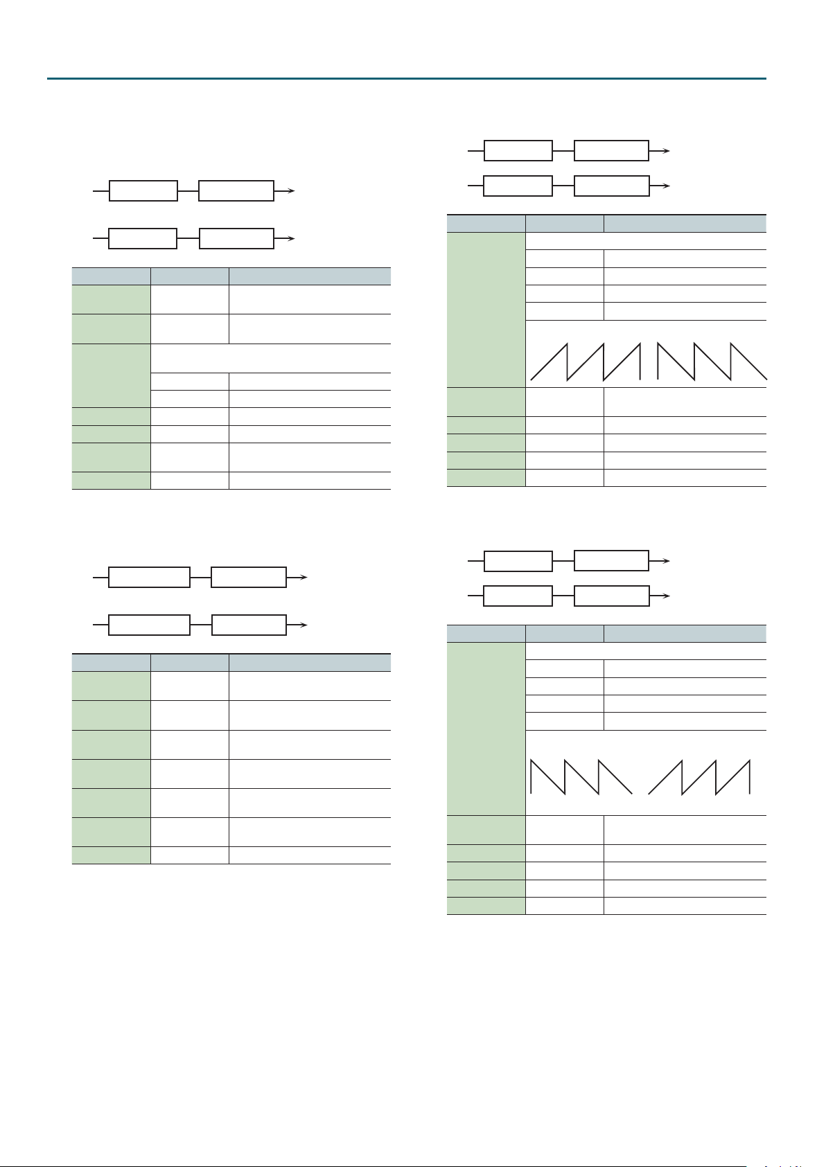
IFX Parameters
L in
R in
R out
L in
R in
R out
L in
R in
R out
SAW1 SAW2
L in
R in
R out
SAW1 SAW2
L
R
L
15: Ring Modulator
This is an eect that applies amplitude modulation (AM) to the
input signal, producing bell-like sounds. You can also change the
modulation frequency in response to changes in the volume of the
sound sent into the eect.
Ring Mod
Ring Mod
Parameter Value Explanation
Frequency 0–127
Sens 0–127
Determines whether the frequency modulation moves
Polarity
Low Gain -15–+15 dB Gain of the low frequency range
High Gain -15–+15 dB Gain of the high frequency range
Balance
Level 0–127 Output level
towards higher frequencies or lower frequencies.
UP Higher frequencies
DOWN Lower frequencies
D100:0W–
D0:100W
2-Band EQ
2-Band EQ
Adjusts the frequency at which
modulation is applied.
Adjusts the amount of frequency
modulation applied.
Volume balance between the direct
sound (D) and the eect sound (W)
L out
17: Tremolo
Cyclically modulates the volume to add tremolo eect to the sound.
Tremolo
Tremolo
Parameter Value Explanation
Modulation Wave
TRI Triangle wave
SQR Square wave
SIN Sine wave
Mod Wave
Rate
Depth 0–127 Depth to which the eect is applied
Low Gain -15–+15 dB Gain of the low range
High Gain -15–+15 dB Gain of the high range
Level 0–127 Output Level
SAW1/2 Sawtooth wave
0.05–10.00 Hz,
note
2-Band EQ
2-Band EQ
Frequency of the change
L out
16: Step Ring Modulator
This is a ring modulator that uses a 16-step sequence to vary the
frequency at which modulation is applied.
Step Ring Mod
Step Ring Mod
Parameter Value Explanation
Step 01-16 0–127
Rate
Attack 0–127
Low Gain -15–+15 dB
High Gain -15–+15 dB
Balance
Level 0–127 Output volume
0.05–10.00 Hz,
note
D100:0W–
D0:100W
2-Band EQ
2-Band EQ
Frequency of ring modulation at each
step
Rate at which the 16-step sequence
will cycle
Speed at which the modulation
frequency changes between steps
Amount of boost/cut for the
low-frequency range
Amount of boost/cut for the
high-frequency range
Volume balance of the original sound
(D) and eect sound (W)
L out
18: Auto Pan
Cyclically modulates the stereo location of the sound.
Auto Pan
Auto Pan
Parameter Value Explanation
Modulation Wave
TRI Triangle wave
SQR Square wave
SIN Sine wave
Mod Wave
Rate
Depth 0–127 Depth to which the eect is applied
Low Gain -15–+15 dB Gain of the low range
High Gain -15–+15 dB Gain of the high range
Level 0–127 Output Level
SAW1/2 Sawtooth wave
0.05–10.00 Hz,
note
2-Band EQ
2-Band EQ
Frequency of the change
L out
R
74

IFX Parameters
L in
R in
L out
R out
L in
R in
R out
L out
R out
L in
R in
19: Step Pan
This uses a 16-step sequence to vary the panning of the sound.
Step Pan
Step Pan
Parameter Value Explanation
Step 01-16 L64–63R Pan at each step
Rate
Attack 0–127
Input Sync Sw OFF, ON
Input Sync
Threshold
Level 0–127 Output volume
0.05–10.00 Hz,
note
0–127
Rate at which the 16-step sequence
will cycle
Speed at which the pan changes
between steps
Species whether an input note will
cause the sequence to resume from
the rst step of the sequence (ON) or
not (OFF)
Volume at which an input note will be
detected
20: Slicer
By applying successive cuts to the sound, this eect turns a
conventional sound into a sound that appears to be played as a
backing phrase. This is especially eective when applied to sustaintype sounds.
Slicer
Slicer
Parameter Value Explanation
Step 01-16 0–127 Level at each step
Rate
Attack 0–127
Input Sync Sw OFF, ON
Input Sync
Threshold
Mode
Shue 0–127
Level 0–127 Output level
0.05–10.00 Hz,
note
0–127
Sets the manner in which the volume changes as one step
progresses to the next.
LEGATO
SLASH
Rate at which the 16-step sequence
will cycle
Speed at which the level changes
between steps
Species whether an input note will
cause the sequence to resume from
the rst step of the sequence (ON) or
not (OFF)
Volume at which an input note will be
detected
The change in volume from one step’s
level to the next remains unaltered.
If the level of a following step is the
same as the one preceding it, there is
no change in volume.
The level is momentarily set to 0
before progressing to the level
of the next step. This change in
volume occurs even if the level of
the following step is the same as the
preceding step.
Timing of volume changes in levels
for even-numbered steps (step 2, step
4, step 6...).
The higher the value, the later the
beat progresses.
L out
21: Rotary
The Rotary eect simulates the sound of the rotary speakers often
used with the electric organs of the past. Since the movement of
the high range and low range rotors can be set independently, the
unique type of modulation characteristic of these speakers can be
simulated quite closely. This eect is most suitable for electric organ
Tones.
Rotary
Parameter Value Explanation
Simultaneously switch the rotational speed of the low
frequency rotor and high frequency rotor.
Speed
Woofer Slow
Speed
Woofer Fast
Speed
Woofer
Acceleration
Woofer Level 0–127 Volume of the low frequency rotor
Tweeter Slow
Speed
Tweeter Fast
Speed
Tweeter
Acceleration
Tweeter Level 0–127
Separation 0–127 Spatial dispersion of the sound
Level 0–127 Output Level
SLOW
FAST
0.05–10.00 Hz
0.05–10.00 Hz
0–15
0.05–10.00 Hz
0.05–10.00 Hz
0–15
Slows down the rotation to the Slow
Rate.
Speeds up the rotation to the Fast
Rate.
Slow speed (SLOW) of the low
frequency rotor
Fast speed (FAST ) of the low
frequency rotor
Adjusts the time it takes the low
frequency rotor to reach the newly
selected speed when switching from
fast to slow (or slow to fast) speed.
Lower values will require longer times.
Settings of the high frequency rotor
The parameters are the same as for
the low frequency rotor
75

IFX Parameters
R out
L in
R in
L in
R out
Balance D
Balance D
R in
R out
L in
Balance D
Balance D
22: VK Rotary
This type provides modied response for the rotary speaker, with the
low end boosted further.
This eect features the same specications as the VK-7’s built-in
rotary speaker.
2-Band EQ
Rotary
2-Band EQ
Parameter Value Explanation
Rotational speed of the rotating speaker
Speed
Brake OFF, ON
Woofer Slow
Speed
Woofer Fast
Speed
Woofer Trans Up 0–127
Woofer Trans
Down
Woofer Level 0–127 Volume of the woofer
Tweeter Slow
Speed
Tweeter Fast
Speed
Tweeter Trans Up 0–127
Tweeter Trans
Down
Tweeter Level 0–127
Spread 0–10
Low Gain -15–+15 dB Gain of the low range
High Gain -15–+15 dB Gain of the high range
Level 0–127 Output Level
SLOW Slow
FAST Fast
Switches the rotation of the rotary
speaker.
When this is turned on, the rotation
will gradually stop. When it is turned
o, the rotation will gradually resume.
0.05–10.00 Hz
0.05–10.00 Hz
0–127
0.05–10.00 Hz
0.05–10.00 Hz
0–127
Low-speed rotation speed of the
woofer
High-speed rotation speed of the
woofer
Adjusts the rate at which the woofer
rotation speeds up when the rotation
is switched from SLOW to FAST.
Adjusts the rate at which the woofer
rotation speeds up when the rotation
is switched from FAST to SLOW.
Settings of the tweeter
The parameters are the same as for
the woofer.
Sets the rotary speaker stereo image.
The higher the value set, the wider the
sound is spread out.
23: Chorus
This is a stereo chorus. A lter is provided so that you can adjust the
timbre of the chorus sound.
2-Band
EQ
Chorus
Chorus
R in
Parameter Value Explanation
Type of lter
OFF No lter is used
Filter Type
LPF
HPF
Balance W
Balance W
2-Band
EQ
Cuts the frequency range above the
Cuto Freq
Cuts the frequency range below the
Cuto Freq
L out
L out
Parameter Value Explanation
Cuto Freq 200–8000 Hz
Pre Delay 0.0–100 msec
Rate
Depth 0–127 Depth of modulation
Phase 0–180 deg Spatial spread of the sound
Low Gain -15–+15 dB Gain of the low range
High Gain -15–+15 dB Gain of the high range
Balance
Level 0–127 Output Level
0.05–10.00 Hz,
note
D100:0W–
D0:100W
Center frequency when using the lter
to cut a specic frequency range
Adjusts the delay time from the direct
sound until the chorus sound is heard.
Frequency of modulation
Volume balance between the direct
sound (D) and the chorus sound (W)
24: Flanger
This is a stereo anger (The LFO has the same phase for left and
right.).
It produces a metallic resonance that rises and falls like a jet airplane
taking o or landing. A lter is provided so that you can adjust the
timbre of the anged sound.
2-Band
EQ
Flanger
Feedback
Feedback
Flanger
Parameter Value Explanation
Type of lter
OFF No lter is used
Filter Type
Cuto Freq 200–8000 Hz
Pre Delay 0.0–100 msec
Rate
Depth 0–127 Depth of modulation
Phase 0–180 deg Spatial spread of the sound
Feedback -98–+98 %
Low Gain -15–+15 dB Gain of the low range
High Gain -15–+15 dB Gain of the high range
Balance
Level 0–127 Output Level
LPF
HPF
0.05–10.00 Hz,
note
D100:0W–
D0:100W
Balance W
Balance W
2-Band
EQ
Cuts the frequency range above the
Cuto Freq
Cuts the frequency range below the
Cuto Freq
Center frequency when using the lter
to cut a specic frequency range
Adjusts the delay time from when the
direct sound begins until the anger
sound is heard.
Frequency of modulation
Adjusts the proportion of the anger
sound that is fed back into the eect.
Negative (-) settings will invert the
phase.
Volume balance between the direct
sound (D) and the anger sound (W)
L out
76

IFX Parameters
R in
R out
L in
Balance D
Balance D
L in
L out
R out
Balance D
L in
R in
L out
R out
Balance D
L in
R in
R out
Balance D
Balance D
25: Step Flanger
This is a anger in which the anger pitch changes in steps. The
speed at which the pitch changes can also be specied in terms of a
note-value of a specied tempo.
2-Band
EQ
Step Flanger
Feedback
Feedback
Step Flanger
Balance W
Balance W
2-Band
EQ
Parameter Value Explanation
Type of lter
OFF No lter is used
Filter Type
Cuto Freq 200–8000 Hz
Pre Delay 0.0–100 msec
Rate
Depth 0–127 Depth of modulation
Phase 0–180 deg Spatial spread of the sound
Feedback -98–+98 %
Step Rate
Low Gain -15–+15 dB Gain of the low range
High Gain -15–+15 dB Gain of the high range
Balance
Level 0–127 Output Level
LPF
HPF
0.05–10.00 Hz,
note
0.10–20.00 Hz,
note
D100:0W–
D0:100W
Cuts the frequency range above the
Cuto Freq
Cuts the frequency range below the
Cuto Freq
Center frequency when using the lter
to cut a specic frequency range
Adjusts the delay time from when the
direct sound begins until the anger
sound is heard.
Frequency of modulation
Adjusts the proportion of the anger
sound that is fed back into the eect.
Negative (-) settings will invert the
phase.
Rate (period) of pitch change
Volume balance between the direct
sound (D) and the anger sound (W)
26: Hexa-Chorus
Uses a six-phase chorus (six layers of chorused sound) to give
richness and spatial spread to the sound.
Balance D
Hexa Chorus
R in
Parameter Value Explanation
Pre Delay 0.0–100 msec
Rate
Depth 0–127 Depth of modulation
Pre Delay
Deviation
Depth Deviation -20–+20
0.05–10.00 Hz,
note
0–20
Balance W
Balance W
Adjusts the delay time from the direct
sound until the chorus sound is heard.
Frequency of modulation
Adjusts the dierences in Pre Delay
between each chorus sound.
Adjusts the dierence in modulation
depth between each chorus sound.
L out
Parameter Value Explanation
0–20
Pan Deviation
Balance
Level 0–127 Output Level
0 All chorus sounds will be in the center.
20
D100:0W–
D0:100W
Adjusts the dierence in stereo
location between each chorus sound.
Each chorus sound will be spaced
at 60 degree intervals relative to the
center.
Volume balance between the direct
sound (D) and the chorus sound (W)
27: Tremolo Chorus
This is a chorus eect with added Tremolo (cyclic modulation of
volume).
Balance D
Balance W
Tremolo Chorus
Balance W
Parameter Value Explanation
Pre Delay 0.0–100 msec
Chorus Rate
Chorus Depth 0–127 Modulation depth of the chorus eect
Tremolo Rate
Tremolo
Separation
Tremolo Phase 0–180 deg Spread of the tremolo eect
Balance
Level 0–127 Output Level
0.05–10.00 Hz,
note
0.05–10.00 Hz,
note
0–127 Spread of the tremolo eect
D100:0W–
D0:100W
Adjusts the delay time from the direct
sound until the chorus sound is heard.
Modulation frequency of the chorus
eect
Modulation frequency of the tremolo
eect
Volume balance between the direct
sound (D) and the tremolo chorus
sound (W)
28: Space-D
This is a multiple chorus that applies two-phase modulation in stereo.
It gives no impression of modulation, but produces a transparent
chorus eect.
2-Band
EQ
Space D
Space D
Parameter Value Explanation
Pre Delay 0.0–100 msec
Rate
Depth 0–127 Depth of modulation
Phase 0–180 deg Spatial spread of the sound
Low Gain -15–+15 dB Gain of the low range
High Gain -15–+15 dB Gain of the high range
Balance
Level 0–127 Output Level
0.05–10.00 Hz,
note
D100:0W–
D0:100W
Balance W
Balance W
2-Band
EQ
Adjusts the delay time from the direct
sound until the chorus sound is heard.
Frequency of modulation
Volume balance between the direct
sound (D) and the chorus sound (W)
L out
77

IFX Parameters
L
R
2-Band
EQ
R out
L
R
2-Band
EQ
R out
L
R
2-Band
EQ
R out
29: 3D Chorus
This applies a 3D eect to the chorus sound. The chorus sound will
be positioned 90 degrees left and 90 degrees right.
EQ
L out
3D Chorus
2-Band
Parameter Value Explanation
Type of lter
OFF No lter is used
Filter Type
Cuto Freq 200–8000 Hz
Pre Delay 0.0–100 msec
Rate
Depth 0–127 Modulation depth of the chorus eect
Phase 0–180 deg Spatial spread of the sound
Output Mode
Low Gain -15–+15 dB Gain of the low range
High Gain -15–+15 dB Gain of the high range
Balance
Level 0–127 Output Level
LPF
HPF
0.05–10.00 Hz,
note
The optimal 3D eect will be achieved.
Speaker When using speakers
Phones When using headphones
D100:0W–
D0:100W
Cuts the frequency range above the
Cuto Freq
Cuts the frequency range below the
Cuto Freq
Center frequency when using the lter
to cut a specic frequency range
Adjusts the delay time from the direct
sound until the chorus sound is heard.
Frequency of modulation
Volume balance between the direct
sound (D) and the chorus sound (W)
30: 3D Flanger
This applies a 3D eect to the anger sound. The anger sound will
be positioned 90 degrees left and 90 degrees right.
EQ
3D Flanger
2-Band
Parameter Value Explanation
Type of lter
OFF No lter is used
Filter Type
Cuto Freq 200–8000 Hz
Pre Delay 0.0–100 msec
Rate
Depth 0–127 Depth of modulation
Phase 0–180 deg Spatial spread of the sound
Feedback -98–+98 %
LPF
HPF
0.05–10.00 Hz,
note
Cuts the frequency range above the
Cuto Freq
Cuts the frequency range below the
Cuto Freq
Center frequency when using the lter
to cut a specic frequency range
Adjusts the delay time from when the
direct sound begins until the anger
sound is heard.
Frequency of modulation
Adjusts the proportion of the anger
sound that is fed back into the eect.
Negative (-) settings will invert the
phase.
L out
Parameter Value Explanation
The optimal 3D eect will be achieved.
Output Mode
Low Gain -15–+15 dB Gain of the low range
High Gain -15–+15 dB Gain of the high range
Balance
Level 0–127 Output Level
Speaker When using speakers
Phones When using headphones
D100:0W–
D0:100W
Volume balance between the direct
sound (D) and the anger sound (W)
31: 3D Step Flanger
This applies a 3D eect to the step anger sound. The anger sound
will be positioned 90 degrees left and 90 degrees right.
EQ
3D Step Flanger
2-Band
Parameter Value Explanation
Type of lter
OFF No lter is used
Filter Type
Cuto Freq 200–8000 Hz
Pre Delay 0.0–100 msec
Rate
Depth 0–127 Depth of modulation
Phase 0–180 deg Spatial spread of the sound
Feedback -98–+98 %
Step Rate
Output Mode
Low Gain -15–+15 dB Gain of the low range
High Gain -15–+15 dB Gain of the high range
Balance
Level 0–127 Output Level
LPF
HPF
0.05–10.00 Hz,
note
0.10–20.00 Hz,
note
The optimal 3D eect will be achieved.
Speaker When using speakers
Phones When using headphones
D100:0W–
D0:100W
Cuts the frequency range above the
Cuto Freq
Cuts the frequency range below the
Cuto Freq
Center frequency when using the lter
to cut a specic frequency range
Adjusts the delay time from when the
direct sound begins until the anger
sound is heard.
Frequency of modulation
Adjusts the proportion of the anger
sound that is fed back into the eect.
Negative (-) settings will invert the
phase.
Rate (period) of pitch change
Volume balance between the direct
sound (D) and the anger sound (W)
L out
78

IFX Parameters
R in
R out
L in
L out
R in
R out
L in
L out
R in
R out
L in
L out
32: 2 Band Chorus
A chorus eect that lets you apply an eect independently to the
low-frequency and high-frequency ranges.
Split
Split
Parameter Value Explanation
Split Freq 200–8000 Hz
Low Pre Delay 0.0–100 msec
Low Rate
Low Depth 0–127
Low Phase 0–180 deg
High Pre Delay 0.0–100 msec
High Rate
High Depth 0–127
High Phase 0–180 deg
Balance
Level 0–127 Output Level
0.05–10.00 Hz,
note
0.05–10.00 Hz,
note
D100:0W–
D0:100W
High Band Chorus
Low Band Chorus
High Band Chorus
Low Band Chorus
Frequency at which the low and high
ranges will be divided
Delay time from when the original
sound is heard to when the low-range
chorus sound is heard
Rate at which the low-range chorus
sound is modulated
Modulation depth for the low-range
chorus sound
Spaciousness of the low-range chorus
sound
Delay time from when the original
sound is heard to when the highrange chorus sound is heard
Rate at which the low-range chorus
sound is modulated
Modulation depth for the high-range
chorus sound
Spaciousness of the high-range
chorus sound
Volume balance of the original sound
(D) and chorus sound (W)
Parameter Value Explanation
Proportion of the low-range anger
Low Feedback -98–+98 %
High Pre Delay 0.0–100 msec
High Rate
High Depth 0–127
High Phase 0–180 deg
High Feedback -98–+98 %
Balance
Level 0–127 Output Level
0.05–10.00 Hz,
note
D100:0W–
D0:100W
sound that is to be returned to the
input (negative (-) values invert the
phase)
Delay time from when the original
sound is heard to when the highrange anger sound is heard
Rate at which the high-range anger
sound is modulated
Modulation depth for the high-range
anger sound
Spaciousness of the high-range
anger sound
Proportion of the high-range anger
sound that is to be returned to the
input (negative (-) values invert the
phase)
Volume balance of the original sound
(D) and anger sound (W)
34: 2 Band Step Flanger
A step anger that lets you apply an eect independently to the
low-frequency and high-frequency ranges.
High Band Step Flanger
Split
Split
High Band Feedback
Low Band Step Flanger
Low Band Feedback
High Band Feedback
High Band Step Flanger
Low Band Feedback
Low Band Step Flanger
33: 2 Band Flanger
A anger that lets you apply an eect independently to the
low-frequency and high-frequency ranges.
High Band Flanger
Split
Split
Parameter Value Explanation
Split Freq 200–8000 Hz
Low Pre Delay 0.0–100 msec
Low Rate
Low Depth 0–127
Low Phase 0–180 deg
0.05–10.00 Hz,
note
High Band Feedback
Low Band Flanger
Low Band Feedback
High Band Feedback
High Band Flanger
Low Band Feedback
Low Band Flanger
Frequency at which the low and high
ranges will be divided
Delay time from when the original
sound is heard to when the low-range
anger sound is heard
Rate at which the low-range anger
sound is modulated
Modulation depth for the low-range
anger sound
Spaciousness of the low-range anger
sound
Parameter Value Explanation
Split Freq 200–8000 Hz
Low Pre Delay 0.0–100 msec
Low Rate
Low Depth 0–127
Low Phase 0–180 deg
Low Feedback -98–+98 %
Low Step Rate
High Pre Delay 0.0–100 msec
High Rate
High Depth 0–127
High Phase 0–180 deg
0.05–10.00 Hz,
note
0.10–20.00 Hz,
note
0.05–10.00 Hz,
note
Frequency at which the low and high
ranges will be divided
Delay time from when the original
sound is heard to when the low-range
anger sound is heard
Rate at which the low-range anger
sound is modulated
Modulation depth for the low-range
anger sound
Spaciousness of the low-range anger
sound
Proportion of the low-range anger
sound that is to be returned to the
input (negative (-) values invert the
phase)
Rate at which the steps will cycle for
the low-range anger sound
Delay time from when the original
sound is heard to when the highrange anger sound is heard
Rate at which the high-range anger
sound is modulated
Modulation depth for the high-range
anger sound
Spaciousness of the high-range
anger sound
79

IFX Parameters
L in
R in
L out
R out
L in
R in
L out
R out
L in
R in
L out
R out
L in
R in
L out
R out
L in
R in
L out
R out
Parameter Value Explanation
Proportion of the high-range anger
High Feedback -98–+98 %
High Step Rate
Balance
Level 0–127 Output Level
0.10–20.00 Hz,
note
D100:0W–
D0:100W
sound that is to be returned to the
input (negative (-) values invert the
phase)
Rate at which the steps will cycle for
the high-range anger sound
Volume balance of the original sound
(D) and anger sound (W)
35: Overdrive
Creates a soft distortion similar to that produced by vacuum tube
ampliers.
Over drive
Parameter Value Explanation
Drive 0–127
Type of guitar amp
SMALL Small amp
Amp Type
Low Gain -15–+15 dB Gain of the low range
High Gain -15–+15 dB Gain of the high range
Pan L64–63R Stereo location of the output sound
Level 0–127 Output Level
BUILT-IN Single-unit type amp
2-STACK Large double stack amp
3-STACK Large triple stack amp
Amp
Simulator
2-Band
EQ
Degree of distortion
Also changes the volume.
36: Distortion
Produces a more intense distortion than Overdrive. The parameters
are the same as for “35: Overdrive.”
Distortion
Amp
Simulator
2-Band
EQ
37: VS Overdrive
This is an overdrive that provides heavy distortion.
Overdrive
Parameter Value Explanation
Drive 0–127
Tone 0–127 Sound quality of the Overdrive eect
Amp Sw OFF, ON Turns the Amp Simulator on/o.
Type of guitar amp
SMALL Small amp
Amp Type
Low Gain -15–+15 dB Gain of the low range
High Gain -15–+15 dB Gain of the high range
Pan L64–63R Stereo location of the output sound
Level 0–127 Output Level
BUILT-IN Single-unit type amp
2-STACK Large double stack amp
3-STACK Large triple stack amp
Amp
Simulator
80
2-Band
EQ
Degree of distortion
Also changes the volume.
Pan L
Pan R
Pan L
Pan R
Pan L
Pan R
38: VS Distortion
This is a distortion eect that provides heavy distortion. The
parameters are the same as for “37: VS Overdrive.”
Distortion
Amp
Simulator
2-Band
EQ
39: Guitar Amp Simulator
This is an eect that simulates the sound of a guitar amplier.
Pre Amp
Parameter Value Explanation
Pre Amp Sw OFF, ON Turns the amp switch on/o.
JC-120,
CLEAN TWIN,
MATCH DRIVE,
BG LEAD,
MS1959I,
MS1959II,
Pre Amp Type
Pre Amp Volume 0–127
Pre Amp Master 0–127 Volume of the entire pre-amp
Pre Amp Gain
Pre Amp Bass
Pre Amp Middle
Pre Amp Treble
Pre Amp
Presence
Pre Amp Bright OFF, ON
Speaker Sw OFF, ON
Speaker Type
Mic Setting 1, 2, 3
Mic Level 0–127 Volume of the microphone
Direct Level 0–127 Volume of the direct sound
Pan L64–63R Stereo location of the output sound
Level 0–127 Output Level
MS1959I+II,
SLDN LEAD,
METAL 5150,
METAL LEAD,
OD-1,
OD-2 TURBO,
DISTORTION,
FUZZ
LOW, MIDDLE,
HIGH
0–127
0–127
(See the
following table)
Speaker
Type of guitar amp
Volume and amount of distortion of
the amp
Amount of pre-amp distortion
Tone of the bass/mid/treble frequency
range
Middle cannot be set if “MATCH
DRIVE” is selected as the Pre Amp
Type.
Tone for the ultra-high frequency
range
Turning this “On” produces a sharper
and brighter sound.
This parameter applies to the
“JC-120,” “CLEAN TWIN,” and “BG
LEAD” Pre Amp Types.
Determines whether the signal passes
through the speaker (ON), or not
(OFF).
Type of speaker
Adjusts the location of the
microphone that’s capturing the
sound of the speaker.
This can be adjusted in three steps,
from 1 to 3, with the microphone
becoming more distant as the value
increases.
Pan L
Pan R
Pan L
Pan R

IFX Parameters
L in
R in
R out
L in
R in
R out
L in
R in
R out
R in
R out
L in
Balance D
Balance D
R in
R out
L in
Balance D
Balance D
Specications for each Speaker Type
The speaker column indicates the diameter of each speaker unit (in
inches) and the number of units.
Type Cabinet Speaker Microphone
SMALL 1 Small open-back enclosure 10 Dynamic
SMALL 2 Small open-back enclosure 10 Dynamic
MIDDLE Open back enclosure 12 x 1 Dynamic
JC-120 Open back enclosure 12 x 2 Dynamic
BUILT-IN 1 Open back enclosure 12 x 2 Dynamic
BUILT-IN 2 Open back enclosure 12 x 2 Condenser
BUILT-IN 3 Open back enclosure 12 x 2 Condenser
BUILT-IN 4 Open back enclosure 12 x 2 Condenser
BUILT-IN 5 Open back enclosure 12 x 2 Condenser
BG STACK 1 Sealed enclosure 12 x 2 Condenser
BG STACK 2 Large sealed enclosure 12 x 2 Condenser
MS STACK 1 Large sealed enclosure 12 x 4 Condenser
MS STACK 2 Large sealed enclosure 12 x 4 Condenser
METAL STACK Large double stack 12 x 4 Condenser
2-STACK Large double stack 12 x 4 Condenser
3-STACK Large triple stack 12 x 4 Condenser
40: Compressor
Flattens out high levels and boosts low levels, smoothing out
uctuations in volume.
Compressor
Compressor
Parameter Value Explanation
Attack 0–127
Threshold 0–127
Post Gain 0–+18 dB Adjusts the output gain.
Low Gain -15–+15 dB Gain of the low range
High Gain -15–+15 dB Gain of the high range
Level 0–127 Output Level
2-Band EQ
2-Band EQ
Sets the time from when the input
exceeds the Threshold until the
volume starts being compressed
Adjusts the volume at which
compression begins
L out
Parameter Value Explanation
High Gain -15–+15 dB Gain of the high range
Level 0–127 Output Level
42: Gate
Cuts the reverb’s delay according to the volume of the sound
sent into the eect. Use this when you want to create an articialsounding decrease in the reverb’s decay.
Gate
L out
Gate
Parameter Value Explanation
Threshold 0–127
Type of gate
Mode
Attack 0–127
Hold 0–127
Release 0–127
Balance
Level 0–127 Output Level
GATE
DUCK (Ducking)
D100:0W–
D0:100W
Volume level at which the gate begins
to close
The gate will close when the volume
of the original sound decreases,
cutting the original sound.
The gate will close when the volume
of the original sound increases,
cutting the original sound.
Adjusts the time it takes for the gate
to fully open after being triggered.
Adjusts the time it takes for the gate
to start closing after the source sound
falls beneath the Threshold.
Adjusts the time it takes the gate to
fully close after the hold time.
Volume balance between the direct
sound (D) and the eect sound (W)
43: Delay
This is a stereo delay.
When Feedback Mode is NORMAL:
2-Band
EQ
Delay
Feedback
Feedback
Balance W
L out
41: Limiter
Compresses signals that exceed a specied volume level, preventing
distortion from occurring.
Limiter
Limiter
Parameter Value Explanation
Release 0–127
Threshold 0–127
Ratio
Post Gain 0–+18 dB Adjusts the output gain.
Low Gain -15–+15 dB Gain of the low range
1.5:1, 2:1, 4:1,
100:1
2-Band EQ
2-Band EQ
Adjusts the time after the signal
volume falls below the Threshold
Level until compression is no longer
applied.
Adjusts the volume at which
compression begins
Compression ratio
L out
Delay
When Feedback Mode is CROSS:
Delay
Feedback
Feedback
Delay
Balance W
2-Band
EQ
2-Band
EQ
Balance W
Balance W
2-Band
EQ
L out
81

IFX Parameters
L in
R in
R out
EQ
2-Band
R in
R out
L in
L out
2-Band
EQ
R in R out
L in
Balance D
Balance D
R in
R out
L in
Balance D
Balance D
Parameter Value Explanation
Delay Left
Delay Right
Phase Left
Phase Right
Feedback Mode NORMAL, CROSS
Feedback -98–+98 %
HF Damp
Low Gain -15–+15 dB Gain of the low range
High Gain -15–+15 dB Gain of the high range
Balance
Level 0–127 Output Level
0–1300 msec,
note
Phase of the left delay sound
NORMAL Non-inverted
INVERT Inverted
Phase of the right delay sound
NORMAL Non-inverted
INVERT Inverted
200–8000 Hz,
BYPASS
D100:0W–
D0:100W
Adjusts the time until the delay sound
is heard.
Selects the way in which delay sound
is fed back into the eect (See the
gures.).
Adjusts the amount of the delay
sound that’s fed back into the eect.
Negative (-) settings invert the phase.
Adjusts the frequency above which
sound fed back to the eect is ltered
out. If you don’t want to lter out any
high frequencies, set this parameter
to BYPASS.
Volume balance between the direct
sound (D) and the delay sound (W)
44: Long Delay
A delay that provides a long delay time.
Long Delay
Feedback
Parameter Value Explanation
Delay time from when the original
sound is heard to when the delay
sound is heard
Phase of the delay (NORMAL:
non-inverted, INVERT: inverted)
Proportion of the delay sound that is
to be returned to the input (negative
(-) values invert the phase)
Frequency at which the highfrequency content of the delayed
sound will be cut
(BYPASS: no cut)
Volume balance of the original sound
(D) and delay sound (W)
0–2600 msec,
note
NORMAL,
INVERSE
200–8000 Hz,
BYPASS
D100:0W–
D0:100W
Delay Time
Phase
Feedback -98–+98 %
HF Damp
Pan L64–63R Panning of the delay sound
Low Gain -15–+15 dB Gain of the low range
High Gain -15–+15 dB Gain of the high range
Balance
Level 0–127 Output Level
Pan L
Pan R
EQ
2-Band
L out
45: Serial Delay
This delay connects two delay units in series. Feedback can be
applied independently to each delay unit, allowing you to produce
complex delay sounds.
Pan L
Delay 1
Feedback 1
Parameter Value Explanation
Delay 1 Time
Delay 1
Feedback
Delay 1 HF Damp
Delay 2 Time
Delay 2
Feedback
Delay 2 HF Damp
Pan L64–63R Panning of the delay sound
Low Gain -15–+15 dB Gain of the low range
High Gain -15–+15 dB Gain of the high range
Balance
Level 0–127 Output Level
0–1300 msec,
note
-98–+98 %
200–8000 Hz,
BYPASS
0–1300 msec,
note
-98–+98 %
200–8000 Hz,
BYPASS
D100:0W–
D0:100W
Delay 2
Feedback 2
Delay time from when sound is input
to delay 1 until the delay sound is
heard
Proportion of the delay sound that is
to be returned to the input of delay 1
(negative (-) values invert the phase)
Frequency at which the highfrequency content of the delayed
sound of delay 1 will be cut (BYPASS:
no cut)
Proportion of the delay sound that is
to be returned to the input of delay 2
(negative (-) values invert the phase)
Proportion of the delay sound that is
to be returned to the input of delay 2
(negative (-) values invert the phase)
Frequency at which the highfrequency content of the delayed
sound of delay 2 will be cut (BYPASS:
no cut)
Volume balance of the original sound
(D) and delay sound (W)
Pan R
2-Band
46: Modulation Delay
Adds modulation to the delayed sound.
When Feedback Mode is NORMAL:
2-Band
EQ
Delay
Feedback
Feedback
Delay
Modulation
Modulation
When Feedback Mode is CROSS:
Delay
Feedback
Feedback
Delay
Modulation
Modulation
Balance W
Balance W
2-Band
EQ
2-Band
EQ
Balance W
Balance W
2-Band
EQ
EQ
L out
L out
82

IFX Parameters
L in
R in
R out
Balance D
Balance D
L in
R in
L out
R out
Balance D
Balance D
L
L in
R in
R out
Balance D
Balance D
Parameter Value Explanation
Delay Left
Delay Right
Feedback Mode NORMAL, CROSS
Feedback -98–+98 %
HF Damp
Rate
Depth 0–127 Depth of modulation
Phase 0–180 deg Spatial spread of the sound
Low Gain -15–+15 dB Gain of the low range
High Gain -15–+15 dB Gain of the high range
Balance
Level 0–127 Output Level
0–1300 msec,
note
200–8000 Hz,
BYPASS
0.05–10.00 Hz,
note
D100:0W–
D0:100W
Adjusts the time until the delay sound
is heard.
Selects the way in which delay sound
is fed back into the eect
(See the gures.)
Adjusts the amount of the delay
sound that’s fed back into the eect.
Negative (-) settings invert the phase.
Adjusts the frequency above which
sound fed back to the eect is ltered
out. If you don’t want to lter out any
high frequencies, set this parameter
to BYPASS.
Frequency of modulation
Volume balance between the direct
sound (D) and the delay sound (W)
47: 3Tap Pan Delay
Produces three delay sounds; center, left and right.
Left Tap
Triple Tap Delay
Feedback
Parameter Value Explanation
Delay Left/Right/
Center
Center Feedback -98–+98 %
HF Damp
Left/Right/
Center Level
Low Gain -15–+15 dB Gain of the low range
High Gain -15–+15 dB Gain of the high range
Balance
Level 0–127 Output Level
0–2600 msec,
note
200–8000 Hz,
BYPASS
0–127 Volume of each delay
D100:0W–
D0:100W
Center Tap
Right Tap
Adjusts the time from the original
sound until the left, right, and center
delayed sounds are heard
Adjusts the amount of the delay
sound that’s fed back into the eect.
Negative (-) settings invert the phase.
Adjusts the frequency above which
sound fed back to the eect is ltered
out. If you do not want to lter out any
high frequencies, set this parameter
to BYPASS.
Volume balance between the direct
sound (D) and the delay sound (W)
Balance W
Balance W
2-Band
EQ
2-Band
EQ
L out
48: 4Tap Pan Delay
This eect has four delays.
2-Band
Feedback
Delay 1
Quadruple
Tap Delay
Delay 4
Delay 2
Delay 3
EQ
Balance W
Balance W
2-Band
EQ
2 3
1
Stereo location of each delay
4
R
Parameter Value Explanation
Delay 1-4 Time
Delay 1
Feedback
HF Damp
Delay 1-4 Level 0–127 Volume of each delay
Low Gain -15–+15 dB Gain of the low range
High Gain -15–+15 dB Gain of the high range
Balance
Level 0–127 Output Level
0–2600 msec,
note
-98–+98 %
200–8000 Hz,
BYPASS
D100:0W–
D0:100W
Adjusts the time from the original
sound until delay sounds 1–4 are
heard
Adjusts the amount of the delay
sound that’s fed back into the eect.
Negative (-) settings invert the phase.
Adjusts the frequency above which
sound fed back to the eect is ltered
out. If you do not want to lter out any
high frequencies, set this parameter
to BYPASS.
Volume balance between the direct
sound (D) and the delay sound (W)
49: Multi Tap Delay
This eect provides four delays. Each of the Delay Time parameters
can be set to a note length based on the selected tempo. You can
also set the panning and level of each delay sound.
2-Band
Feed
back
Delay 1
Delay 3
Multi Tap Delay
Delay 4
Delay 2
Parameter Value Explanation
Delay 1-4 Time
Delay 1
Feedback
HF Damp
Delay 1-4 Pan L64–63R Stereo location of Delays 1–4
Delay 1-4 Level 0–127 Output level of Delays 1–4
Low Gain -15–+15 dB Gain of the low range
High Gain -15–+15 dB Gain of the high range
0–2600 msec,
note
-98–+98 %
200–8000 Hz,
BYPASS
Adjusts the time until Delays 1–4 are
heard.
Adjusts the amount of the delay
sound that’s fed back into the eect.
Negative (-) settings invert the phase.
Adjusts the frequency above which
sound fed back to the eect is ltered
out. If you don’t want to lter out
any the high frequencies, set this
parameter to BYPASS.
EQ
Balance W
Balance W
2-Band
EQ
L out
83

IFX Parameters
L in
R in
R out
EQ
2-Band
L in
R in
R out
EQ
2-Band
L
R
2-Band
EQ
R out
Parameter Value Explanation
Balance
Level 0–127 Output Level
D100:0W–
D0:100W
Volume balance between the direct
sound (D) and the eect sound (W)
50: Reverse Delay
This is a reverse delay that adds a reversed and delayed sound to the
input sound. A tap delay is connected immediately after the reverse
delay.
Feedback
Rev. Delay
Parameter Value Explanation
Threshold 0–127
Rev Delay Time
Rev Delay
Feedback
Rev Delay HF
Damp
Rev Delay Pan L64–63R Panning of the reverse delay sound
Rev Delay Level 0–127 Volume of the reverse delay sound
Delay 1 - 3 Time
Delay 3
Feedback
Delay HF Damp
Delay 1 Pan,
Delay 2 Pan
Delay 1 Level,
Delay 2 Level
Low Gain -15–+15 dB Gain of the low range
High Gain -15–+15 dB Gain of the high range
Balance
Level 0–127 Output Level
Rev
D1
Delay
D2
D3
Volume at which the reverse delay will
begin to be applied
0–1300 msec,
note
-98–+98 %
200–8000 Hz,
BYPASS
0–1300 msec,
note
-98–+98 %
200–8000 Hz,
BYPASS
L64–63R Panning of the tap delay sounds
0–127 Volume of the tap delay sounds
D100:0W–
D0:100W
Delay time from when sound is input
into the reverse delay until the delay
sound is heard
Proportion of the delay sound that
is to be returned to the input of the
reverse delay (negative (-) values
invert the phase)
Frequency at which the highfrequency content of the reversedelayed sound will be cut (BYPASS:
no cut)
Delay time from when sound is input
into the tap delay until the delay
sound is heard
Proportion of the delay sound that
is to be returned to the input of the
tap delay (negative (-) values invert
the phase)
Frequency at which the hi-frequency
content of the tap delay sound will be
cut (BYPASS: no cut)
Volume balance of the original sound
(D) and delay sound (W)
EQ
2-Band
L out
51: Shue Delay
Adds a shue to the delay sound, giving the sound a bouncy delay
eect with a swing feel.
Feedback
Delay A
A
Delay
Delay B
Parameter Value Explanation
Delay Time
Shue Rate 0–100
Acceleration 0–15
Feedback -98–+98 %
HF Damp
Pan A/B L64–63R Stereo location of Delay A/B
Level A/B 0–127 Volume of delay A/B
Low Gain -15–+15 dB Gain of the low range
High Gain -15–+15 dB Gain of the high range
Balance
Level 0–127 Output Level
0–2600 msec,
note
200–8000 Hz,
BYPASS
D100:0W–
D0:100W
B
Adjusts the time until the delay sound
is heard.
Adjusts the ratio (as a percentage) of
the time that elapses before Delay
B sounds relative to the time that
elapses before the Delay A sounds.
When set to 100, the delay times are
the same.
Adjusts the speed which the Delay
Time changes from the current setting
to its specied new setting.
Adjusts the amount of the delay that’s
feedback into the eect. Negative (-)
settings invert the phase.
Adjusts the frequency above which
sound fed back to the eect is ltered
out. If you don’t want to lter out any
high frequencies, set this parameter
to BYPASS.
Volume balance between the direct
sound (D) and the eect sound (W)
2-Band
52: 3D Delay
This applies a 3D eect to the delay sound. The delay sound will be
positioned 90 degrees left and 90 degrees right.
3D Delay L
Level
3D Delay C
Feedback
3D Delay R
Parameter Value Explanation
Delay Left
Delay Right
Delay Center
Center Feedback -98–+98 %
HF Damp
0–2600 msec,
note
200–8000 Hz,
BYPASS
Adjusts the delay time from the direct
sound until the delay sound is heard.
Adjusts the proportion of the delay
sound that is fed back into the eect.
Negative (-) settings will invert the
phase.
Adjusts the frequency above which
sound fed back to the eect will be
cut. If you do not want to cut the high
frequencies, set this parameter to
BYPASS.
EQ
2-Band
EQ
L out
L out
84

IFX Parameters
R in
R out
L in
L in
R in
R out
Balance D
2-Band
L in
R in
L out
R out
Direct Level
Parameter Value Explanation
Left Level
0–127 Output level of the delay soundRight Level
Center Level
The optimal 3D eect will be achieved.
Output Mode
Low Gain -15–+15 dB Gain of the low range
High Gain -15–+15 dB Gain of the high range
Balance
Level 0–127 Output Level
Speaker When using speakers
Phones When using headphones
D100:0W–
D0:100W
Volume balance between the direct
sound (D) and the eect sound (W)
53: Time Ctrl Delay
A stereo delay in which the delay time can be varied smoothly.
2-Band EQ
Time Ctrl Delay
Feedback
Feedback
Time Ctrl Delay
Pan L
Pan R
2-Band EQ
Parameter Value Explanation
Delay Time
Acceleration 0–15
Feedback -98–+98 %
HF Damp
Low Gain -15–+15 dB Gain of the low range
High Gain -15–+15 dB Gain of the high range
Balance
Level 0–127 Output Level
0–1300 msec,
note
200–8000 Hz,
BYPASS
D100:0W–
D0:100W
Adjusts the time until the delay is
heard.
Adjusts the speed which the Delay
Time changes from the current setting
to a specied new setting. The rate
of change for the Delay Time directly
aects the rate of pitch change.
Adjusts the amount of the delay that’s
fed back into the eect. Negative (-)
settings invert the phase.
Adjusts the frequency above which
sound fed back to the eect is ltered
out. If you do not want to lter out any
high frequencies, set this parameter
to BYPASS.
Volume balance between the direct
sound (D) and the delay sound (W)
54: Long Time Ctrl Delay
A delay in which the delay time can be varied smoothly, and allowing
an extended delay to be produced.
Balance D
Time Control Delay
Feedback
Parameter Value Explanation
Delay Time
0–2600 msec,
note
Adjusts the time until the delay is
heard.
EQ
Balance W
Balance W
2-Band
EQ
L out
L out
Parameter Value Explanation
Adjusts the speed which the Delay
Time changes from the current setting
Acceleration 0–15
Feedback -98–+98 %
HF Damp
Pan L64–63R Stereo location of the delay
Low Gain -15–+15 dB Gain of the low range
High Gain -15–+15 dB Gain of the high range
Balance
Level 0–127 Output Level
200–8000 Hz,
BYPASS
D100:0W–
D0:100W
to a specied new setting.
The rate of change for the Delay
Time directly aects the rate of pitch
change.
Adjusts the amount of the delay that’s
fed back into the eect. Negative (-)
settings invert the phase.
Adjusts the frequency above which
sound fed back to the eect is ltered
out. If you do not want to lter out any
high frequencies, set this parameter
to BYPASS.
Volume balance between the direct
sound (D) and the delay sound (W)
55: Tape Echo
A virtual tape echo that produces a realistic tape delay sound. This
simulates the tape echo section of a Roland RE-201 Space Echo.
Direct Level
Tape Echo
Parameter Value Explanation
Mode
Repeat Rate 0–127
Intensity 0–127 Amount of delay repeats
Bass -15–+15 dB
Treble -15–+15 dB
Head S Pan
Head M Pan
Head L Pan
Tape Distortion 0–5
Wow/Flutter
Rate
Wow/Flutter
Depth
Echo Level 0–127 Volume of the echo sound
Direct Level 0–127 Volume of the original sound
Level 0–127 Output Level
S, M, L, S+M, S+L,
M+L, S+M+L
L64–63R
0–127
0–127 Depth of wow/utter
Echo Level
Echo Level
Combination of playback heads to use
Select from three dierent heads with
dierent delay times.
S: short
M: middle
L: long
Tape speed
Increasing this value will shorten the
spacing of the delayed sounds.
Boost/cut for the lower range of the
echo sound
Boost/cut for the upper range of the
echo sound
Independent panning for the short,
middle, and long playback heads
Amount of tape-dependent distortion
to be added
This simulates the slight tonal
changes that can be detected by
signal-analysis equipment. Increasing
this value will increase the distortion.
Speed of wow/utter (complex
variation in pitch caused by tape wear
and rotational irregularity)
85

IFX Parameters
R in
R out
L in
2-Band
EQ
L in
R in
R out
2-Band
EQ
R in
R out
L in
2-Band
EQ
56: Lo Noise
In addition to a lo- eect, this adds various types of noise such as
white noise and disc noise.
EQ
Lo-Fi
Noise Gen.
Lo-Fi
2-Band
Parameter Value Explanation
LoFi Type 1–9
Type of lter that follows the LoFi eect
OFF No lter is used
Post Filter Type
Post Filter Cuto 200–8000 Hz Center frequency of the lter
W/P Noise Type WHITE, PINK
W/P Noise LPF
W/P Noise Level 0–127 Volume of the white/pink noise
Disc Noise Type LP, EP, SP, RND
Disc Noise LPF
Disc Noise Level 0–127 Volume of the record noise
Hum Noise Type 50 Hz, 60 Hz Frequency of the hum noise
Hum Noise LPF
Hum Noise Level 0–127 Volume of the hum noise
Low Gain -15–+15 dB Gain of the low range
High Gain -15–+15 dB Gain of the high range
Balance
Level 0–127 Output Level
LPF
HPF
200–8000 Hz,
BYPASS
200–8000 Hz,
BYPASS
200–8000 Hz,
BYPASS
D100:0W–
D0:100W
Degrades the sound quality. The
sound quality grows poorer as this
value is increased.
Cuts the frequency range above the
Cuto.
Cuts the frequency range below the
Cuto.
Switch between white noise and pink
noise.
Center frequency of the low pass
lter applied to the white/pink noise
(BYPASS: no cut)
Type of record noise
The frequency at which the noise is
heard depends on the selected type.
Adjusts the cuto frequency of the
low pass lter applied to the record
noise. If you don’t want to lter
out any high frequencies, set this
parameter to BYPASS.
Center frequency of the low pass lter
applied to the hum noise (BYPASS:
no cut)
Volume balance between the direct
sound (D) and the eect sound (W)
L out
57: Lo Compress
This is an eect that intentionally degrades the sound quality for
creative purposes.
Compressor
Compressor
Parameter Value Explanation
Selects the type of lter applied to the sound before it
Pre Filter Type
LoFi Type 1–9
Post Filter Type
Post Filter Cuto 200–8000 Hz Basic frequency of the Post Filter
Low Gain -15–+15 dB Gain of the low range
High Gain -15–+15 dB Gain of the high range
Balance
Level 0–127 Output Level
passes through the Lo-Fi eect.
1 Compressor o
2–6 Compressor on
Type of lter
OFF No lter is used
LPF
HPF
D100:0W–
D0:100W
Lo-Fi
Lo-Fi
Degrades the sound quality. The
sound quality grows poorer as this
value is increased.
Cuts the frequency range above the
Cuto
Cuts the frequency range below the
Cuto
Volume balance between the direct
sound (D) and the eect sound (W)
EQ
2-Band
58: Lo Radio
In addition to a Lo-Fi eect, this eect also generates radio noise.
EQ
Lo-Fi
Radio
Lo-Fi
2-Band
Parameter Value Explanation
LoFi Type 1–9
Type of lter
OFF No lter is used
Post Filter Type
Post Filter Cuto 200–8000 Hz Basic frequency of the Post Filter
Radio Detune 0–127
Radio Noise
Level
Low Gain -15–+15 dB Gain of the low range
High Gain -15–+15 dB Gain of the high range
Balance
Level 0–127 Output Level
LPF
HPF
0–127 Volume of the radio noise
D100:0W–
D0:100W
Degrades the sound quality. The
sound quality grows poorer as this
value is increased.
Cuts the frequency range above the
Cuto.
Cuts the frequency range below the
Cuto.
Simulates the tuning noise of a radio.
As this value is raised, the tuning drifts
further.
Volume balance between the direct
sound (D) and the eect sound (W)
L out
L out
86

IFX Parameters
L in
R in
R out
L in
R in
R out
Balance D
Balance D
L in
R in
R out
L in
R in
R out
Balance D
Balance D
59: Telephone
This eect produces a mued sound, like that heard through a
telephone.
Telephone
L out
Telephone
Parameter Value Explanation
Voice Quality 0–15 Audio quality of the telephone voice
Treble -15–+15 dB Bandwidth of the telephone voice
Balance
Level 0–127 Output Level
D100:0W–
D0:100W
Volume balance between the direct
sound (D) and the eect sound (W)
60: Phonograph
Simulates a sound recorded on an analog record and played back on
a record player. This eect also simulates the various types of noise
that are typical of a record, and even the rotational irregularities of an
old turntable.
L out
Phonograph
Phonograph
Balance W
Balance W
61: Pitch Shifter
A stereo pitch shifter.
Pitch Shifter
Pitch Shifter
Parameter Value Explanation
Coarse -24–+12 semi
Fine -100–+100 cent
Delay Time
Feedback -98–+98 %
Low Gain -15–+15 dB Gain of the low range
High Gain -15–+15 dB Gain of the high range
Balance
Level 0–127 Output Level
0–1300 msec,
note
D100:0W–
D0:100W
Adjusts the pitch of the pitch shifted
sound in semitone steps.
Adjusts the pitch of the pitch shifted
sound in 2-cent steps.
Adjusts the delay time from the direct
sound until the pitch shifted sound
is heard.
Adjusts the proportion of the pitch
shifted sound that is fed back into the
eect. Negative (-) settings will invert
the phase.
Volume balance between the direct
sound (D) and the pitch shifted sound
(W)
2-Band EQ
2-Band EQ
L out
Parameter Value Explanation
Signal Distortion 0–127 Depth of distortion
Frequency response of the playback
Frequency
Range
Disc Type LP, EP, SP
Scratch Noise
Level
Dust Noise Level 0–127
Hiss Noise Level 0–127 Volume of continuous “hiss”
Total Noise Level 0–127 Volume of overall noise
Wow 0–127
Flutter 0–127
Random 0–127
Total Wow/
Flutter
Balance
Level 0–127 Output Level
0–127
0–127
0–127 Depth of overall rotational irregularity
D100:0W–
D0:100W
system
Decreasing this value will produce the
impression of an old system with a
poor frequency response.
Rotational speed of the turntable
This will aect the frequency of the
scratch noise.
Amount of noise due to scratches on
the record
Volume of noise due to dust on the
record
Depth of long-cycle rotational
irregularity
Depth of short-cycle rotational
irregularity
Depth of indenite-cycle rotational
irregularity
Volume balance between the direct
sound (D) and the eect sound (W)
62: 2Voice Pitch Shifter
Shifts the pitch of the original sound. This 2-voice pitch shifter has
two pitch shifters, and can add two pitch shifted sounds to the
original sound.
2-Band
Level 1
2Voice
Pitch Shifter
Level 2
Parameter Value Explanation
Pitch1 Coarse -24–+12 semi
Pitch1 Fine -100–+100 cent
Pitch1 Delay
Pitch1 Feedback -98–+98 %
Pitch1 Pan L64–63R
Pitch1 Level 0–127 Volume of the Pitch Shift1 sound
Pitch2 Coarse -24–+12 semi
Pitch2 Fine -100–+100 cent
Pitch2 Delay
Pitch2 Feedback -98–+98 %
Pitch2 Pan L64–63R
Pitch2 Level 0–127
Low Gain -15–+15 dB Gain of the low range
0–1300 msec,
note
0–1300 msec,
note
Pan 1 L
Pan 1 R
Pan 2 L
Pan 2 R
Adjusts the pitch of Pitch Shift 1 in
semitone steps.
Adjusts the pitch of Pitch Shift Pitch 1
in 2-cent steps.
Adjusts the delay time from the direct
sound until the Pitch Shift 1 sound
is heard.
Adjusts the proportion of the pitch
shifted sound that is fed back into the
eect. Negative (-) settings will invert
the phase.
Stereo location of the Pitch Shift 1
sound
Settings of the Pitch Shift 2 sound.
The parameters are the same as for
the Pitch Shift 1 sound.
EQ
Balance W
Balance W
2-Band
EQ
L out
87

IFX Parameters
L in
R out
2-Band
EQ
L in
R in
R out
Balance D
2-Band
L in
R in
R out
Balance D
2-Band
Parameter Value Explanation
High Gain -15–+15 dB Gain of the high range
Balance
Level 0–127 Output Level
D100:0W–
D0:100W
Volume balance between the direct
sound (D) and the pitch shifted sound
(W)
63: Step Pitch Shifter
A pitch shifter in which the amount of pitch shift is varied by a
16-step sequence.
Step Pitch Shifter
Step Pitch Shifter
R in
Parameter Value Explanation
Step 01-16 -24–+12 semi
Rate
Attack 0–127
Gate Time 0–127
Fine -100–+100 cent
Delay Time
Feedback -98–+98 %
Low Gain -15–+15 dB Gain of the low range
High Gain -15–+15 dB Gain of the high range
Balance
Level 0–127 Output Level
0.05–10.0 Hz,
note
0–1300 msec,
note
D100:0W–
D0:100W
Amount of pitch shift at each step
(semitone units)
Rate at which the 16-step sequence
will cycle
Speed at which the amount of pitch
shift changes between steps
Duration of the pitch shifted sound at
each step
Pitch shift adjustment for all steps
(2-cent units)
Delay time from the original sound
until the pitch-shifted sound is heard
Proportion of the pitch-shifted sound
that is to be returned to the input
(negative (-) values invert the phase)
Volume balance of the original sound
(D) and pitch-shifted sound (W)
2-Band
64: Reverb
Adds reverberation to the sound, simulating an acoustic space.
EQ
L out
Parameter Value Explanation
Adjusts the frequency above which
the reverberant sound will be cut.
HF Damp
Low Gain -15–+15 dB Gain of the low range
High Gain -15–+15 dB Gain of the high range
Balance
Level 0–127 Output Level
200–8000 Hz,
BYPASS
D100:0W–
D0:100W
As the frequency is set lower, more
of the high frequencies will be cut,
resulting in a softer and more muted
reverberance. If you do not want
to cut the high frequencies, set this
parameter to BYPASS.
Volume balance between the direct
sound (D) and the reverb sound (W)
65: Gated Reverb
This is a special type of reverb in which the reverberant sound is cut
o before its natural length.
Balance D
EQ
Balance W
Reverb
Balance W
2-Band
EQ
Parameter Value Explanation
Type of reverb
NORMAL Conventional gated reverb
Type
Pre Delay 0.0–100 msec
Gate Time 5–500 msec
Low Gain -15–+15 dB Gain of the low range
High Gain -15–+15 dB Gain of the high range
Balance
Level 0–127 Output Level
REVERSE Backwards reverb
SWEEP1
SWEEP2
D100:0W–
D0:100W
The reverberant sound moves from
right to left
The reverberant sound moves from
left to right
Adjusts the delay time from the direct
sound until the reverb sound is heard.
Adjusts the time from when the
reverb is heard until it disappears.
Volume balance between the direct
sound (D) and the reverb sound (W)
L out
Balance D
EQ
Balance W
Reverb
Balance W
2-Band
EQ
Parameter Value Explanation
Type of reverb
ROOM1 Dense reverb with short decay
ROOM2 Sparse reverb with short decay
Type
Pre Delay 0.0–100 msec
Time 0–127 Time length of reverberation
STAGE1 Reverb with greater late reverberation
STAGE2 Reverb with strong early reections
HALL1 Reverb with clear reverberance
HALL2 Reverb with rich reverberance
Adjusts the delay time from the direct
sound until the reverb sound is heard.
88
L out

IFX Parameters
L in
R in
L out
Balance W
Balance W
Balance D
L in
R in
Balance W
Balance W
Balance D
Balance D
L in
R in
L out
Balance W
Balance W
Balance D
L in
R in
L out
Balance W
Balance W
Balance D
L in
R in
Balance W
Balance W
Balance D
Balance D
66: Overdrive g Chorus
Balance D
Overdrive
Chorus
R out
Parameter Value Explanation
Overdrive Drive 0–127
Overdrive Pan L64–63R Stereo location of the overdrive sound
Chorus Pre Delay 0.0–100 msec
Chorus Rate
Chorus Depth 0–127 Depth of modulation
Chorus Balance
Level 0–127 Output Level
0.05–10.00 Hz,
note
D100:0W–
D0:100W
Degree of distortion
Also changes the volume.
Adjusts the delay time from the direct
sound until the chorus sound is heard.
Frequency of modulation
Adjusts the volume balance between
the sound that is sent through the
chorus (W) and the sound that is not
sent through the chorus (D).
67: Overdrive g Flanger
Feedback
L out
68: Overdrive g Delay
Balance D
Overdrive
Parameter Value Explanation
Overdrive Drive 0–127
Overdrive Pan L64–63R Stereo location of the overdrive sound
Delay Time
Delay Feedback -98–+98 %
Delay HF Damp
Delay Balance
Level 0–127 Output Level
0–2600 msec,
note
200–8000 Hz,
BYPASS
D100:0W–
D0:100W
Delay
Feedback
Degree of distortion
Also changes the volume.
Adjusts the delay time from the direct
sound until the delay sound is heard.
Adjusts the proportion of the delay
sound that is fed back into the eect.
Negative (-) settings will invert the
phase.
Adjusts the frequency above which
sound fed back to the eect will be
cut. If you do not want to cut the high
frequencies, set this parameter to
BYPASS.
Adjusts the volume balance between
the sound that is sent through the
delay (W) and the sound that is not
sent through the delay (D).
R out
Overdrive
Flanger
R out
Parameter Value Explanation
Overdrive Drive 0–127
Overdrive Pan L64–63R Stereo location of the overdrive sound
Flanger Pre
Delay
Flanger Rate
Flanger Depth 0–127 Depth of modulation
Flanger
Feedback
Flanger Balance
Level 0–127 Output Level
0.0–100 msec
0.05–10.00 Hz,
note
-98–+98 %
D100:0W–
D0:100W
Degree of distortion
Also changes the volume.
Adjusts the delay time from when the
direct sound begins until the anger
sound is heard.
Frequency of modulation
Adjusts the proportion of the anger
sound that is fed back into the eect.
Negative (-) settings will invert the
phase.
Adjusts the volume balance between
the sound that is sent through the
anger (W) and the sound that is not
sent through the anger (D).
69: Distortion g Chorus
The parameters are essentially the same as in “66: Overdrive g
Chorus,” with the exception of the following two.
Overdrive Drive g Distortion Drive,
Overdrive Pan g Distortion Pan
Balance D
Distortion
Chorus
R out
70: Distortion g Flanger
The parameters are essentially the same as in “67: Overdrive g
Flanger,” with the exception of the following two.
Overdrive Drive g Distortion Drive,
Overdrive Pan g Distortion Pan
Feedback
Distortion
Flanger
L out
R out
89

IFX Parameters
L in
R in
L out
Balance W
Balance W
Balance D
L in
R in
L out
R out
Mix
Enhancer
Balance W
Balance W
Balance D
R in
R out
Mix
Balance W
Balance W
Balance D
L in
R in
L out
Mix
Enhancer
Balance W
R in
Balance W
Balance D
Balance D
Balance D
71: Distortion g Delay
The parameters are essentially the same as in “68: Overdrive g
Delay,” with the exception of the following two.
Overdrive Drive g Distortion Drive,
Overdrive Pan g Distortion Pan
Balance D
Distortion
Delay
Feedback
72: Enhancer g Chorus
Mix
Enhancer
Parameter Value Explanation
Enhancer Sens 0–127 Sensitivity of the enhancer
Enhancer Mix 0–127
Chorus Pre Delay 0.0–100 msec
Chorus Rate
Chorus Depth 0–127 Depth of modulation
Chorus Balance
Level 0–127 Output Level
0.05–10.00 Hz,
note
D100:0W–
D0:100W
Balance D
Chorus
Level of the overtones generated by
the enhancer
Adjusts the delay time from the direct
sound until the chorus sound is heard.
Frequency of modulation
Adjusts the volume balance between
the sound that is sent through the
chorus (W) and the sound that is not
sent through the chorus (D).
R out
74: Enhancer g Delay
Mix
Enhancer
Parameter Value Explanation
Enhancer Sens 0–127 Sensitivity of the enhancer
Enhancer Mix 0–127
Delay Time
Delay Feedback -98–+98 %
Delay HF Damp
Delay Balance
Level 0–127 Output Level
0–2600 msec,
note
200–8000 Hz,
BYPASS
D100:0W–
D0:100W
Balance D
Delay
Feedback
Balance D
Level of the overtones generated by
the enhancer
Adjusts the delay time from the direct
sound until the delay sound is heard.
Adjusts the proportion of the delay
sound that is fed back into the eect.
Negative (-) settings will invert the
phase.
Adjusts the frequency above which
sound fed back to the eect will be
cut. If you do not want to cut the high
frequencies, set this parameter to
BYPASS.
Adjusts the volume balance between
the sound that is sent through the
delay (W) and the sound that is not
sent through the delay (D).
75: Chorus g Delay
L in
Balance W
Chorus
Balance W
Balance D
Delay
Feedback
Balance W
R out
L out
Balance W
R out
73: Enhancer g Flanger
L in
90
Enhancer
Mix
Feedback
Flanger
Enhancer
Parameter Value Explanation
Enhancer Sens 0–127 Sensitivity of the enhancer
Enhancer Mix 0–127
Flanger Pre
Delay
Flanger Rate
Flanger Depth 0–127 Depth of modulation
Flanger
Feedback
Flanger Balance
Level 0–127 Output Level
0.0–100 msec
0.05–10.00 Hz,
note
-98–+98 %
D100:0W–
D0:100W
Balance D
Level of the overtones generated by
the enhancer
Adjusts the delay time from when the
direct sound begins until the anger
sound is heard.
Frequency of modulation
Adjusts the proportion of the anger
sound that is fed back into the eect.
Negative (-) settings will invert the
phase.
Adjusts the volume balance between
the sound that is sent through the
anger (W) and the sound that is not
sent through the anger (D).
L out
Parameter Value Explanation
Chorus Pre Delay 0.0–100 msec
Chorus Rate
Chorus Depth 0–127 Depth of modulation
Chorus Balance
Delay Time
Delay Feedback -98–+98 %
Delay HF Damp
Delay Balance
Level 0–127 Output Level
0.05–10.00 Hz,
note
D100:0W–
D0:100W
0–2600 msec,
note
200–8000 Hz,
BYPASS
D100:0W–
D0:100W
Adjusts the delay time from the direct
sound until the chorus sound is heard.
Frequency of modulation
Volume balance between the direct
sound (D) and the chorus sound (W)
Adjusts the delay time from the direct
sound until the delay sound is heard.
Adjusts the proportion of the delay
sound that is fed back into the eect.
Negative (-) settings will invert the
phase.
Adjusts the frequency above which
sound fed back to the eect will be
cut. If you do not want to cut the high
frequencies, set this parameter to
BYPASS.
Adjusts the volume balance between
the sound that is sent through the
delay (W) and the sound that is not
sent through the delay (D).

IFX Parameters
R in
R out
Balance W
Balance W
Balance D
Balance D
Balance D
R in
L out
R out
Balance W
Balance W
Balance D
Balance D
Balance D
Balance D
L in
R in
R out
3-Band
EQ
76: Flanger g Delay
L in
Feedback
Flanger
Parameter Value Explanation
Flanger Pre
Delay
Flanger Rate
Flanger Depth 0–127 Depth of modulation
Flanger
Feedback
Flanger Balance
Delay Time
Delay Feedback -98–+98 %
Delay HF Damp
Delay Balance
Level 0–127 Output Level
0.0–100 msec
0.05–10.00 Hz,
note
-98–+98 %
D100:0W–
D0:100W
0–2600 msec,
note
200–8000 Hz,
BYPASS
D100:0W–
D0:100W
Balance W
Balance W
Balance D
Delay
Feedback
Adjusts the delay time from when the
direct sound begins until the anger
sound is heard.
Frequency of modulation
Adjusts the proportion of the anger
sound that is fed back into the eect.
Negative (-) settings will invert the
phase.
Volume balance between the direct
sound (D) and the anger sound (W)
Adjusts the delay time from the direct
sound until the delay sound is heard.
Adjusts the proportion of the delay
sound that is fed back into the eect.
Negative (-) settings will invert the
phase.
Adjusts the frequency above which
sound fed back to the eect will be
cut. If you do not want to cut the high
frequencies, set this parameter to
BYPASS.
Adjusts the volume balance between
the sound that is sent through the
delay (W) and the sound that is not
sent through the delay (D).
77: Chorus g Flanger
L in
Balance W
Chorus
Balance W
Parameter Value Explanation
Chorus Pre Delay 0.0–100 msec
Chorus Rate
Chorus Depth 0–127 Modulation depth of the chorus eect
Chorus Balance
Flanger Pre
Delay
Flanger Rate
Flanger Depth 0–127 Modulation depth of the anger eect
Flanger
Feedback
0.05–10.00 Hz,
note
D100:0W–
D0:100W
0.0–100 msec
0.05–10.00 Hz,
note
-98–+98 %
Feedback
Flanger
Adjusts the delay time from the direct
sound until the chorus sound is heard.
Modulation frequency of the chorus
eect
Volume balance between the direct
sound (D) and the chorus sound (W)
Adjusts the delay time from when the
direct sound begins until the anger
sound is heard.
Modulation frequency of the anger
eect
Adjusts the proportion of the anger
sound that is fed back into the eect.
Negative (-) settings will invert the
phase.
L out
Parameter Value Explanation
Flanger Balance
Level 0–127 Output Level
D100:0W–
D0:100W
Adjusts the volume balance between
the sound that is sent through the
anger (W) and the sound that is not
sent through the anger (D).
78: Sympathetic Resonance
On an acoustic piano, holding down the damper pedal allows other
strings to resonate in sympathy with the notes you play, creating rich
and spacious resonances. This eect simulates these sympathetic
resonances.
EQ
Sym. Resonance
3-Band
Parameter Value Explanation
Depth 0–127 Depth of the eect
Damper 0–127
Lid 1–6
Pre LPF
Pre HPF
HF Damp
LF Damp
EQ Low Freq 200, 400 Hz Frequency of the low-range EQ
EQ Low Gain -15–+15 dB Amount of low-range boost/cut
EQ Mid Freq 200–8000 Hz Frequency of the midrange EQ
EQ Mid Gain -15–+15 dB Amount of midrange boost/cut
EQ Mid Q
EQ High Freq
EQ High Gain -15–+15 dB Amount of high-range boost/cut
Peaking Freq 200–8000 Hz
Peaking Gain -15–+15 dB
Peaking Q
Level 0–127 Output Level
16–15000 Hz,
BYPASS
BYPASS,
16–15000 Hz
16–15000 Hz,
BYPASS
BYPASS,
16–15000 Hz
0.5, 1.0, 2.0, 4.0,
8.0
2000, 4000, 8000
Hz
0.5, 1.0, 2.0, 4.0,
8.0
Depth to which the damper pedal is
pressed (controls the resonant sound)
This simulates the actual changes in
sound that occur when the lid of a
grand piano is set at dierent heights.
Frequency of the lter that cuts the
high-frequency content of the input
sound (BYPASS: no cut)
Frequency of the lter that cuts the
low-frequency content of the input
sound (BYPASS: no cut)
Frequency at which the highfrequency content of the resonant
sound will be cut (BYPASS: no cut)
Frequency at which the low-frequency
content of the resonant sound will be
cut (BYPASS: no cut)
Width of midrange (larger values
make the region narrower)
Frequency of the high-range EQ
Frequency of the lter that boosts/
cuts a specic frequency region of the
input sound
Amount of boost/cut produced by the
lter at the specied frequency region
of the input sound
Width of the frequency region
boosted/cut by the Peaking Gain
parameter (larger values make the
region narrower)
L out
91

IFX Parameters
Note
Sixty-fourth-note
triplet
Sixteenth-note
triplet
Dotted sixteenth
note
Quarter note Half-note triplet
Whole-note
triplet
Dotted whole
note
NOTE
If you specify the delay time as a note value, slowing down the
tempo will not change the delay time beyond a certain length.
This is because there is an upper limit for the delay time; if the
delay time is specied as a note value and you slow down the
tempo until this upper limit is reached, the delay time cannot
change any further. This upper limit is the maximum value that
can be specied when setting the delay time as a numerical
value.
Sixty-fourth
note
Dotted thirtysecond note
Eighth note
Dotted half note Whole note
Double note
Thirty-secondnote triplet
Sixteenth note
Quarter-note
triplet
Dotted quarter
note
Thirty-second
note
Eighth-note
triplet
Dotted eighth
note
Half note
Double-note
triplet
When Using 3D Eects
The following 3D eects utilize RSS (Roland Sound Space) technology
to create a spaciousness that cannot be produced by delay, reverb,
chorus, etc.
52: 3D Delay
29: 3D Chorus
30: 3D Flanger
31: 3D Step Flanger
When using these eects, we recommend that you place your
speakers as follows. Also, make sure that the speakers are at a
sucient distance from the walls on either side.
30˚ 30˚
If the left and right speakers are too far apart, or if there is too much
reverberation, the full 3D eect may not appear. Each of these
eects has an “Output Mode” parameter. If the sound from the
OUTPUT jacks is to be heard through speakers, set this parameter to
“Speaker.” If the sound is to be heard through headphones, set it to
“Phones.” This will ensure that the optimal 3D eect will be heard. If
this parameter is not set correctly, the full 3D eect may not appear.
92

MFX Parameters
The multi-eects feature 68 dierent kinds of eects. Some of the eects consist of two or more dierent eects connected in series.
Parameters marked with a sharp “#” can be controlled using a Multi-Eects Control (p. 117) (Two setting items will change simultaneously for “#1” and
“#2”).
Type MFX Name Page
0 Thru −
1 Equalizer p. 94
2 Spectrum p. 94
3 Low Boost p. 94
FILTER
MODULATION
CHORUS
DYNAMICS
DELAY
LO-FI
PITCH
4 Step Filter p. 94
5 Enhancer p. 95
6 Auto Wah p. 95
7 Humanizer p. 95
8 Speaker Simulator p. 95
9 Phaser 1 p. 96
10 Phaser 2 p. 96
11 Phaser 3 p. 96
12 Step Phaser p. 97
13 Multi Stage Phaser p. 97
14 Innite Phaser p. 97
15 Ring Modulator p. 98
16 Tremolo p. 98
17 Auto Pan p. 98
18 Slicer p. 98
19 Rotary 1 p. 99
20 Rotary 2 p. 99
21 Rotary 3 p. 100
22 Chorus p. 100
23 Flanger p. 101
24 Step Flanger p. 101
25 Hexa-Chorus p. 102
26 Tremolo Chorus p. 102
27 Space-D p. 102
28 Overdrive p. 102
29 Distortion p. 102
30 Guitar Amp Simulator p. 103
31 Compressor p. 103
32 Limiter p. 103
33 Gate p. 104
34 Delay p. 104
35 Modulation Delay p. 105
36 3Tap Pan Delay p. 105
37 4Tap Pan Delay p. 105
38 Multi Tap Delay p. 106
39 Reverse Delay p. 106
40 Time Ctrl Delay p. 107
41 LOFI Compress p. 107
42 Bit Crusher p. 107
43 Pitch Shifter p. 107
44 2Voice Pitch Shifter p. 108
Type MFX Name Page
45
Overdrive g Chorus
46
Overdrive g Flanger
47
Overdrive g Delay
48
Distortion g Chorus
49
Distortion g Flanger
50
Distortion g Delay
51
OD/DS g TouchWah
52
OD/DS g AutoWah
53
GuitarAmpSim g Chorus
54
GuitarAmpSim g Flanger
55
GuitarAmpSim g Phaser
COMBINATION
VOCODER 68 Vocoder p. 116
56
GuitarAmpSim g Delay
57
EP AmpSim g Tremolo
58
EP AmpSim g Chorus
59
EP AmpSim g Flanger
60
EP AmpSim g Phaser
61
EP AmpSim g Delay
62
Enhancer g Chorus
63
Enhancer g Flanger
64
Enhancer g Delay
65
Chorus g Delay
66
Flanger g Delay
67
Chorus g Flanger
p. 108
p. 108
p. 109
p. 109
p. 109
p. 109
p. 109
p. 110
p. 110
p. 111
p. 111
p. 112
p. 113
p. 113
p. 113
p. 114
p. 114
p. 115
p. 115
p. 115
p. 115
p. 116
p. 116
93

MFX Parameters
L in
R in
R out
L in
R in
R out
L in
R in
R out
L in
R in
L out
R out
Step Filter
Step Filter
01: Equalizer
This is a four-band stereo equalizer (low, mid x 2, high).
4-Band EQ
4-Band EQ
Parameter Value Explanation
Low Freq 200, 400 Hz Frequency of the low range
Low Gain # -15–+15 dB Gain of the low range
Mid1 Freq 200–8000 Hz Frequency of the middle range 1
Mid1 Gain -15–+15 dB Gain of the middle range 1
Mid1 Q
Mid2 Freq 200–8000 Hz Frequency of the middle range 2
Mid2 Gain -15–+15 dB Gain of the middle range 2
Mid2 Q
High Freq
High Gain # -15–+15 dB Gain of the high range
Level # 0–127 Output Level
0.5, 1.0, 2.0, 4.0,
8.0
0.5, 1.0, 2.0, 4.0,
8.0
2000, 4000, 8000
Hz
Width of the middle range 1
Set a higher value for Q to narrow the
range to be aected.
Width of the middle range 2
Set a higher value for Q to narrow the
range to be aected.
Frequency of the high range
L out
03: Low Boost
Boosts the volume of the lower range, creating powerful lows.
Low Boost
Low Boost
Parameter Value Explanation
Boost Frequency
#
Boost Gain # 0–+12 dB
Boost Width
Low Gain -15–+15 dB Gain of the low frequency range
High Gain -15–+15 dB Gain of the high frequency range
Level 0–127 Output level
50–125 Hz
WIDE, MID,
NARROW
2-Band EQ
2-Band EQ
Center frequency at which the lower
range will be boosted
Amount by which the lower range will
be boosted
Width of the lower range that will be
boosted
L out
04: Step Filter
This is a lter whose cuto frequency can be modulated in steps. You
can specify the pattern by which the cuto frequency will change.
You can use MFX CONTROL to restart the step sequence from the
beginning (p. 117).
02: Spectrum
This is a stereo spectrum. Spectrum is a type of lter which modies
the timbre by boosting or cutting the level at specic frequencies.
Spectrum
Spectrum
Parameter Value Explanation
Band1 (250 Hz)
Band2 (500 Hz)
Band3 (1000 Hz)
Band4 (1250 Hz)
Band5 (2000 Hz)
Band6 (3150 Hz)
Band7 (4000 Hz)
Band8 (8000 Hz)
Q
Level # 0–127 Output Level
-15–+15 dB Gain of each frequency band
0.5, 1.0, 2.0, 4.0,
8.0
Simultaneously adjusts the width
of the adjusted ranges for all the
frequency bands.
L out
Parameter Value Explanation
Step 01–16 0–127 Cuto frequency at each step
Rate #
Attack # 0–127
Filter Type
Filter Slope -12, -24, -36 dB
Filter Resonance
#
Filter Gain 0–+12 dB Amount of boost for the lter output
Level 0–127 Output level
0.05–10.00 Hz,
note
LPF, BPF, HPF,
NOTCH
0–127
Rate of modulation
Speed at which the cuto frequency
changes between steps
Filter type
Frequency range that will pass
through each lter
LPF: frequencies below the cuto
BPF: frequencies in the region of the
cuto
HPF: frequencies above the cuto
NOTCH: frequencies other than the
region of the cuto
Amount of attenuation per octave
-12 dB: gentle
-24 dB: steep
-36 dB: extremely steep
Filter resonance level
Increasing this value will emphasize
the region near the cuto frequency.
94

MFX Parameters
L in
R in
R out
L in
R in
R out
L in
R in
L out
R out
L in
R in
R out
05: Enhancer
Controls the overtone structure of the high frequencies, adding
sparkle and tightness to the sound.
Enhancer
Mix
Enhancer
Parameter Value Explanation
Sens # 0–127 Sensitivity of the enhancer
Mix # 0–127
Low Gain -15–+15 dB Gain of the low range
High Gain -15–+15 dB Gain of the high range
Level 0–127 Output Level
Mix
2-Band
EQ
2-Band
EQ
Level of the overtones generated by
the enhancer
06: Auto Wah
Cyclically controls a lter to create cyclic change in timbre.
Auto Wah
Auto Wah
Parameter Value Explanation
Filter Type LPF, BPF
Manual # 0–127
Peak 0–127
Sens # 0–127
Polarity UP, DOWN
Rate #
Depth # 0–127 Depth of modulation
Phase # 0–180 deg
Low Gain -15–+15 dB Gain of the low range
High Gain -15–+15 dB Gain of the high range
Level 0–127 Output Level
0.05–10.00 Hz,
note
2-Band EQ
2-Band EQ
Type of lter
LPF: The wah eect will be applied
over a wide frequency range.
BPF: The wah eect will be applied
over a narrow frequency range.
Adjusts the center frequency at which
the eect is applied.
Adjusts the amount of the wah eect
that will occur in the range of the
center frequency.
Set a higher value for Q to narrow the
range to be aected.
Adjusts the sensitivity with which the
lter is controlled.
Sets the direction in which the
frequency will change when the
auto-wah lter is modulated.
UP: The lter will change toward a
higher frequency.
DOWN: The lter will change toward a
lower frequency.
Frequency of modulation
Adjusts the degree of phase shift of
the left and right sounds when the
wah eect is applied.
L out
L out
07: Humanizer
Adds a vowel character to the sound, making it similar to a human
voice.
Overdrive
Parameter Value Explanation
Drive Sw OFF, ON Turns Drive on/o.
Drive # 0–127
Vowel1 a, e, i, o, u
Vowel2 a, e, i, o, u
Rate #
Depth # 0–127 Eect depth
Input Sync Sw OFF, ON
Input Sync
Threshold
Manual # 0–100
Low Gain -15–+15 dB Gain of the low frequency range
High Gain -15–+15 dB Gain of the high frequency range
Pan # L64–63R Stereo location of the output
Level 0–127 Output level
0.05–10.00 Hz,
note
0–127 Volume level at which reset is applied
Formant
2-Band
EQ
Degree of distortion
Also changes the volume.
Selects the vowel.
Frequency at which the two vowels
switch
LFO reset on/o
Determines whether the LFO for
switching the vowels is reset by the
input signal (ON) or not (OFF).
Point at which Vowel 1/2 switch
49 or less: Vowel 1 will have a longer
duration.
50: Vowel 1 and 2 will be of equal
duration.
51 or more: Vowel 2 will have a longer
duration.
08: Speaker Simulator
Simulates the speaker type and microphone settings used to record
the speaker sound.
Speaker
Speaker
Parameter Value Explanation
Type
Mic Setting 1, 2, 3
Mic Level # 0–127 Volume of the microphone
Direct Level # 0–127 Volume of the direct sound
Level # 0–127 Output Level
(See the
following table)
Type of speaker
Adjusts the location of the
microphone that is recording the
sound of the speaker.
This can be adjusted in three steps,
with the microphone becoming more
distant in the order of 1, 2, and 3.
L out
Pan L
Pan R
95

MFX Parameters
R in
R out
L in
L in
R in
R out
L in
R in
R out
Specications of each Speaker Type
The speaker column indicates the diameter of each speaker unit (in
inches) and the number of units.
Type Cabinet Speaker Microphone
SMALL 1 small open-back enclosure 10 dynamic
SMALL 2 small open-back enclosure 10 dynamic
MIDDLE open back enclosure 12 x 1 dynamic
JC-120 open back enclosure 12 x 2 dynamic
BUILT-IN 1 open back enclosure 12 x 2 dynamic
BUILT-IN 2 open back enclosure 12 x 2 condenser
BUILT-IN 3 open back enclosure 12 x 2 condenser
BUILT-IN 4 open back enclosure 12 x 2 condenser
BUILT-IN 5 open back enclosure 12 x 2 condenser
BG STACK 1 sealed enclosure 12 x 2 condenser
BG STACK 2 large sealed enclosure 12 x 2 condenser
MS STACK 1 large sealed enclosure 12 x 4 condenser
MS STACK 2 large sealed enclosure 12 x 4 condenser
METAL STACK large double stack 12 x 4 condenser
2-STACK large double stack 12 x 4 condenser
3-STACK large triple stack 12 x 4 condenser
09: Phaser 1
A phase-shifted sound is added to the original sound and modulated.
10: Phaser 2
This simulates an analog phaser of the past.
It is particularly suitable for electric piano.
Phaser
Phaser
Parameter Value Explanation
Rate # 0–100 Frequency of modulation
Color 1, 2 Modulation character
Low Gain -15–+15 dB Gain of the low range
High Gain -15–+15 dB Gain of the high range
Level 0–127 Output Level
2-Band EQ
2-Band EQ
11: Phaser 3
This simulates a dierent analog phaser than Phaser 2.
It is particularly suitable for electric piano.
Phaser
Phaser
2-Band EQ
2-Band EQ
L out
L out
Phaser
Mix
Mix
Phaser
Parameter Value Explanation
Mode
Manual # 0–127
Rate #
Depth 0–127 Depth of modulation
Polarity
Resonance # 0–127 Amount of feedback
Cross Feedback -98–+98 %
Mix # 0–127 Level of the phase-shifted sound
Low Gain -15–+15 dB Gain of the low range
High Gain -15–+15 dB Gain of the high range
Level 0–127 Output Level
4-STAGE,
8-STAGE,
12-STAGE
0.05–10.00 Hz,
note
INVERSE,
SYNCHRO
Number of stages in the phaser
Adjusts the basic frequency from
which the sound will be modulated.
Frequency of modulation
Selects whether the left and right
phase of the modulation will be the
same or the opposite.
INVERSE: The left and right phase
will be opposite. When using a mono
source, this spreads the sound.
SYNCHRO: The left and right phase
will be the same. Select this when
inputting a stereo source.
Adjusts the proportion of the phaser
sound that is fed back into the eect.
Negative (-) value will invert the
phase.
2-Band
EQ
2-Band
EQ
L out
Parameter Value Explanation
Speed # 0–100 Frequency of modulation
Low Gain -15–+15 dB Gain of the low range
High Gain -15–+15 dB Gain of the high range
Level 0–127 Output Level
96

MFX Parameters
R in
R out
L in
Resonance
L in
R in
L out
R out
L in
R in
L out
R out
12: Step Phaser
The phaser eect will be varied gradually.
Step Phaser
Mix
Mix
Step Phaser
Parameter Value Explanation
Mode
Manual # 0–127
Rate #
Depth 0–127 Depth of modulation
Polarity
Resonance # 0–127 Amount of feedback
Cross Feedback -98–+98 %
Step Rate #
Mix # 0–127 Level of the phase-shifted sound
Low Gain -15–+15 dB Level of the phase-shifted sound
High Gain -15–+15 dB Gain of the high range
Level 0–127 Output Level
4-STAGE,
8-STAGE,
12-STAGE
0.05–10.00 Hz,
note
INVERSE,
SYNCHRO
0.10–20.00 Hz,
note
Number of stages in the phaser
Adjusts the basic frequency from
which the sound will be modulated.
Frequency of modulation
Selects whether the left and right
phase of the modulation will be the
same or the opposite.
INVERSE: The left and right phase
will be opposite. When using a mono
source, this spreads the sound.
SYNCHRO: The left and right phase
will be the same. Select this when
inputting a stereo source.
Adjusts the proportion of the phaser
sound that is fed back into the eect.
Negative (-) value will invert the
phase.
Rate of the step-wise change in the
phaser eect
2-Band
2-Band
EQ
EQ
L out
13: Multi Stage Phaser
Extremely high settings of the phase dierence produce a deep
phaser eect.
Multi Stage
Phaser
Parameter Value Explanation
4-STAGE,
8-STAGE,
Mode
Manual # 0–127
Rate #
Depth 0–127 Depth of modulation
Resonance # 0–127 Amount of feedback
Mix # 0–127 Level of the phase-shifted sound
Pan # L64–63R Stereo location of the output sound
Low Gain -15–+15 dB Gain of the low range
High Gain -15–+15 dB Gain of the high range
Level 0–127 Output Level
12-STAGE,
16-STAGE,
20-STAGE,
24-STAGE
0.05–10.00 Hz,
note
Mix
Number of phaser stages
Adjusts the basic frequency from
which the sound will be modulated.
Frequency of modulation
2-Band
EQ
14: Innite Phaser
A phaser that continues raising/lowering the frequency at which the
sound is modulated.
Infinite Phaser 2-Band EQ
Parameter Value Explanation
Mode 1, 2, 3, 4
Speed # -100–+100
Resonance # 0–127 Amount of feedback
Mix # 0–127 Volume of the phase-shifted sound
Pan # L64–63R Panning of the output sound
Low Gain -15–+15 dB
High Gain -15–+15 dB
Level 0–127 Output volume
Higher values will produce a deeper
phaser eect.
Speed at which to raise or lower
the frequency at which the sound is
modulated
(+: upward / -: downward)
Amount of boost/cut for the
low-frequency range
Amount of boost/cut for the
high-frequency range
Pan L
Pan R
Pan L
Pan R
97

MFX Parameters
L in
R in
R out
L in
R in
R out
L in
R in
R out
L in
R in
R out
15: Ring Modulator
This is an eect that applies amplitude modulation (AM) to the
input signal, producing bell-like sounds. You can also change the
modulation frequency in response to changes in the volume of the
sound sent into the eect.
Ring Mod
Ring Mod
Parameter Value Explanation
Frequency # 0–127
Sens # 0–127
Polarity UP, DOWN
Low Gain -15–+15 dB Gain of the low frequency range
High Gain -15–+15 dB Gain of the high frequency range
Balance #
Level 0–127 Output level
D100:0W–
D0:100W
2-Band EQ
2-Band EQ
Adjusts the frequency at which
modulation is applied.
Adjusts the amount of frequency
modulation applied.
Determines whether the frequency
modulation moves towards higher
frequencies (UP) or lower frequencies
(DOWN).
Volume balance between the direct
sound (D) and the eect sound (W)
L out
17: Auto Pan
Cyclically modulates the stereo location of the sound.
Auto Pan
Auto Pan
Parameter Value Explanation
TRI, SQR, SIN,
SAW1, SAW2
Mod Wave
Rate #
Depth # 0–127 Depth to which the eect is applied
Low Gain -15–+15 dB Gain of the low range
High Gain -15–+15 dB Gain of the high range
Level 0–127 Output Level
SAW1 SAW2
R R
L L
0.05–10.00 Hz,
note
2-Band EQ
2-Band EQ
Modulation Wave
TRI: triangle wave
SQR: square wave
SIN: sine wave
SAW1/2: sawtooth wave
Frequency of the change
L out
16: Tremolo
Cyclically modulates the volume to add tremolo eect to the sound.
Tremolo
Tremolo
Parameter Value Explanation
TRI, SQR, SIN,
SAW1, SAW2
Mod Wave
SAW1 SAW2
Rate #
Depth # 0–127 Depth to which the eect is applied
Low Gain -15–+15 dB Gain of the low range
High Gain -15–+15 dB Gain of the high range
Level 0–127 Output Level
0.05–10.00 Hz,
note
2-Band EQ
2-Band EQ
Modulation Wave
TRI: triangle wave
SQR: square wave
SIN: sine wave
SAW1/2: sawtooth wave
Frequency of the change
L out
18: Slicer
By applying successive cuts to the sound, this eect turns a
conventional sound into a sound that appears to be played as a
backing phrase. This is especially eective when applied to sustaintype sounds.
You can use MFX CONTROL to restart the step sequence from the
beginning (p. 117).
Slicer
Slicer
Parameter Value Explanation
Step 01–16 L64–63R Level at each step
Rate #
Attack # 0–127
Input Sync Sw OFF, ON
Input Sync
Threshold
Mode LEGATO, SLASH
0.05–10.00 Hz,
note
0–127
Rate at which the 16-step sequence
will cycle
Speed at which the level changes
between steps
Species whether an input note will
cause the sequence to resume from
the rst step of the sequence (ON) or
not (OFF)
Volume at which an input note will be
detected
Sets the manner in which the volume
changes as one step progresses to
the next.
LEGATO: The change in volume from
one step’s level to the next remains
unaltered. If the level of a following
step is the same as the one preceding
it, there is no change in volume.
SLASH: The level is momentarily
set to 0 before progressing to the
level of the next step. This change
in volume occurs even if the level of
the following step is the same as the
preceding step.
L out
98

MFX Parameters
L out
R out
L in
R in
R out
L in
R in
Parameter Value Explanation
Timing of volume changes in levels
for even-numbered steps (step 2, step
Shue # 0–127
Level 0–127 Output level
4, step 6...).
The higher the value, the later the
beat progresses.
19: Rotary 1
This simulates a classic rotary speaker of the past.
Since the operation of the high-frequency and low-frequency rotors
can be specied independently, the distinctive modulation can be
reproduced realistically. This is most eective on organ tones.
Rotary
Parameter Value Explanation
Simultaneously switch the rotational
speed of the low frequency rotor and
high frequency rotor.
Speed # SLOW, FAST
Woofer Slow
Speed
Woofer Fast
Speed
Woofer
Acceleration
Woofer Level 0–127 Volume of the low frequency rotor
Tweeter Slow
Speed
Tweeter Fast
Speed
Tweeter
Acceleration
Tweeter Level 0–127
Separation 0–127 Spatial dispersion of the sound
Level # 0–127 Output Level
0.05–10.00 Hz
0.05–10.00 Hz
0–15
0.05–10.00 Hz
0.05–10.00 Hz
0–15
SLOW: Slows down the rotation to the
Slow Rate.
FAST: Speeds up the rotation to the
Fast Rate.
Slow speed (SLOW) of the low
frequency rotor
Fast speed (FAST ) of the low
frequency rotor
Adjusts the time it takes the low
frequency rotor to reach the newly
selected speed when switching from
fast to slow (or slow to fast) speed.
Lower values will require longer times.
Settings of the high frequency rotor
The parameters are the same as for
the low frequency rotor
20: Rotary 2
This type provides modied response for the rotary speaker, with the
low end boosted further.
This eect features the same specications as the VK-7’s built-in
rotary speaker.
2-Band EQ
Rotary
2-Band EQ
Parameter Value Explanation
Speed # SLOW, FAST
Brake # OFF, ON
Woofer Slow
Speed
Woofer Fast
Speed
Woofer Trans Up 0–127
Woofer Trans
Down
Woofer Level 0–127 Volume of the woofer
Tweeter Slow
Speed
Tweeter Fast
Speed
Tweeter Trans Up 0–127
Tweeter Trans
Down
Tweeter Level 0–127
Spread 0–10
Low Gain -15–+15 dB Gain of the low range
High Gain -15–+15 dB Gain of the high range
Level # 0–127 Output Level
0.05–10.00 Hz
0.05–10.00 Hz
0–127
0.05–10.00 Hz
0.05–10.00 Hz
0–127
Rotational speed of the rotating
speaker
Switches the rotation of the rotary
speaker.
When this is turned on, the rotation
will gradually stop.
When it is turned o, the rotation will
gradually resume.
Low-speed rotation speed of the
woofer
High-speed rotation speed of the
woofer
Adjusts the rate at which the woofer
rotation speeds up when the rotation
is switched from Slow to Fast.
Adjusts the rate at which the woofer
rotation speeds up when the rotation
is switched from Fast to Slow.
Settings of the tweeter
The parameters are the same as for
the woofer.
Sets the rotary speaker stereo image.
The higher the value set, the wider the
sound is spread out.
L out
99

MFX Parameters
L in
L in
R in
R out
Balance D
Balance D
21: Rotary 3
This type includes an overdrive. By distorting the sound you can
produce the intense organ sound used in hard rock.
RotaryOverdrive
R in
Parameter Value Explanation
Speed # SLOW, FAST
Brake # OFF, ON
OD Switch OFF, ON Overdrive on/o
OD Gain # 0–127
OD Drive # 0–127 Degree of distortion
OD Level 0–127 Volume of the overdrive
Woofer Slow
Speed
Woofer Fast
Speed
Woofer Trans Up 0–127
Woofer Trans
Down
Woofer Level 0–127 Volume of the woofer
Tweeter Slow
Speed
Tweeter Fast
Speed
Tweeter Trans Up 0–127
Tweeter Trans
Down
Tweeter Level 0–127
Spread 0–10
Low Gain -15–+15 dB Gain of the low range
High Gain -15–+15 dB Gain of the high range
Level # 0–127 Output Level
0.05–10.00 Hz
0.05–10.00 Hz
0–127
0.05–10.00 Hz
0.05–10.00 Hz
0–127
Rotational speed of the rotating
speaker
Switches the rotation of the rotary
speaker.
When this is turned on, the rotation
will gradually stop.
When it is turned o, the rotation will
gradually resume.
Overdrive input level
Higher values will increase the
distortion.
Low-speed rotation speed of the
woofer
High-speed rotation speed of the
woofer
Adjusts the rate at which the woofer
rotation speeds up when the rotation
is switched from Slow to Fast.
Adjusts the rate at which the woofer
rotation speeds up when the rotation
is switched from Fast to Slow.
Settings of the tweeter
The parameters are the same as for
the woofer.
Sets the rotary speaker stereo image.
The higher the value set, the wider the
sound is spread out.
L out
R out
22: Chorus
This is a stereo chorus. A lter is provided so that you can adjust the
timbre of the chorus sound.
2-Band
EQ
Chorus
Chorus
Parameter Value Explanation
Filter Type OFF, LPF, HPF
Cuto Freq 200–8000 Hz Basic frequency of the lter
Pre Delay 0.0–100.0 ms
Rate #
Depth 0–127 Depth of modulation
Phase 0–180 deg Spatial spread of the sound
Low Gain -15–+15 dB Gain of the low range
High Gain -15–+15 dB Gain of the high range
Balance #
Level 0–127 Output Level
0.05–10.00 Hz,
note
D100:0W–
D0:100W
Balance W
Balance W
2-Band
EQ
Type of lter
OFF: no lter is used
LPF: cuts the frequency range above
the Cuto Freq
HPF: cuts the frequency range below
the Cuto Freq
Adjusts the delay time from the direct
sound until the chorus sound is heard.
Frequency of modulation
Volume balance between the direct
sound (D) and the chorus sound (W)
L out
100
 Loading...