

OP 00 SERVICE NOTES
ep-85

| TABLE OF CONTENTS | Page |
|---|---|
| SPECIFICATIONS | 1 |
| DISASSEMBLY | 1 |
| LOCATION OF CONTROLS & REAR VIEW | 2 |
| EXPLODED VIEW | 3 |
| KEYBOARD PARTS LIST | 4 |
| STAND EXPLODED VIEW & PARTS LIST KS-9E | 4 |
| BLOCK DIAGRAM | 5 |
| MAIN PCB ASSY | 6 |
| CIRCUIT DIAGRAM MAIN PCB ASSY | 7 |
| PIANO MODULE PCB ASSY & CIRCUIT DIAGRAM | 8 |
| CONTROL PCB ASSY & CIRCUIT DIAGRAM | 9 |
| HEADPHONE PCB ASSY & CIRCUIT DIAGRAM | 9 |
| RIGHT CONTACT PCB ASSY w/RUBBER CONTACT & CIRCUIT DIAGRAM | 10 |
| LEFT CONTACT PCB ASSY w/RUBBER CONTACT & CIRCUIT DIAGRAM | 10 |
| PARTS LIST | 11 |
| IDENTIFYING VERSION NUMBER | 12 |
| TEST MODE | 12/13 |
| AUDIO TEST | 13 |
| FACTORY SETUP | 13 |

SPECIFICATIONS
| - Keyboard | 88 keys, velocity sensitive | |
|---|---|---|
| - Polyiphony | 28 voices | |
| - Sounds |
8 selectable via dedicated front-panel b
E.PIANO, VIBRAPHONE, HARPSICHOR CHOIR), 241 Tones + 9 Drums Sets (se |
outtons (PIANO1, PIANO2,
D, ORGAN, STRINGS, lectable via MIDI) |
| - Digital effects | Digital Chorus, Digital Reverb | |
| - Recorder | Records and plays back note and pedal ges. 1 songs (±1000 notes) | data as well as tempo chan |
| -Tuning function | ± 50 cents (TUNE knob) | |
| - Controls |
VOLUME slider (global volume), Pianist
Music Style selection buttons (Ballad, F BossaN, Rock'N Shuffle, Sl Rock, Latin METRONOME (on/off) button, INTRO/E TRANSPOSE ▲/▼ buttons, KEY START/ PLAY/DEMO buttons, Tone selection bu E.Piano, Vibraphone, Harpsichord, Orga REVERB buttons (Rear panel), TUNE k |
: VOLUME ▲/▼ buttons,
Pop, SI Swing, Swing, , SI Waltz, Rag Time), NDING button, TEMPO/KEY STOP button, Recorder REC ttons (Piano1, Piano2, an, Strings, Choir), CHORUS nob. |
| - Finish | Stage-piano look (black) | |
| - Connectors | DC 12V / 1700mA (for ACJ/ASA adapto | r), MIDI IN/OUT connectors, |
| Pedal DAMPER & SOFT jacks, INPUT ( | L/Mono, R) jacks, OUTPUT | |
| (L/R) jacks,2 X PHONES jack (front sid | e) | |
| - Speakers | 12cm x2 | |
| - Output power | 5 W x2 | |
| - Dimensions | 1326 (W) x 382 (D) x 114 (H) mm | |
| -Weight | 15 Kg. (without AC- Adaptor) | |
| - Power consumption | 1700mA (DC 9V) | |
| -Supplied accessories | DP-6 footswitch pedal | |
| •• | Owner's. Manual (I/SP/DUTCH) EP85/95 | (K6018264) |
| Owner's. Manual (E/D/F) EP85/95 | (K6018265) | |
| MIDI Guide | (K6018109) | |
| Music Rest | (22195654KK) | |
| Power Adaptor ACJ 120V (117V) | (22448612) | |
| Power Adaptor ACJ 230V (230V) | (2244861101) | |
| Power Adaptor ACJ 230VE (230VE) | (2244861001) | |
| Power Adaptor ACJ 240VA (240VA) | (22448614) | |
| - Options | Headphones: RH-120, RH-80, RH-20 | |
| Footswitches (pedals): DP-2,DP-6 | ||
| KS-9E Keyboard stand |

2
LOCATION OF CONTROLS

2
| EXPI | LO | D | E | D | V | IE' | W |
|---|
| NO | PARIS NAME | PARIS NUMBER |
|---|---|---|
| 1 | VARNISHED BOTTOM CABINET | 7698804000 |
| 2 | SPACER 3M ART. SJ5012 | J2359101 |
| 3 | MAIN BOARD PCB ASSY | 7698801000 |
| 4 | VARN+SILK. SOCKET SUPPORT | 7698805000 |
| 5 | SPEAKER 4 OHM 120.20B/FX | K2418103 |
| 6 | CONTROLS PCB ASSY | 7698802000 |
| 7 | VIBRATION DAMPER K600 | K2268145 |
| 8 | OVAL DIFFUSER F/4 LINEAR LEDS | K2238117 |
| 9 | VARN+SILK. TOP CABINET | 7698803000 |
| 10 | GRILL F/LOUDSPEAKER | K2248125 |
| 11 | HEADPHONES PCB ASSY | 7695902000 |
| 12 | MUSIC STOPPER | K2238113 |
| 13 | 88-KEY TP8P KEYBOARD ASSY | 7698908000 |
| 14 | MUSIC REST | 22195654KK |
| 15 | HEADPHONES FIXING BASE | K2128105 |
| 16 | ROT.POT. 10KB 90° MONO | 13279884 |
| 17 | DIN SOCKET MG/PR 5L | 13429664RI |
| 18 | JACK SOCKET HLJ0520-01-110 | 13449125 |
| 19 | SWITCH SDDWA-1401A | 13129135 |
| 20 | DC SUPPLY SOCKET HEC 2305-01-230 | 13449726 |
| 21 | JACK SOCKET YKB 21-5006 | 13449252 |
| 22 | SELF TAP.SCREW 3.5x19 TCTCPRBZ | J2289128 |
| 23 | SCREW 2.9x10 TCTCPR TROP | J2289125 |
| 24 | SELF TAP.SCREW 3.5x9.5 TCPRTFR | J2289115 |
| 25 | SCREW 2.9x13 TCTCPR TRP | J2289130 |
| 26 | 2P COAXIAL CBL ASSY (28) -2C | 7698905000 |
| 27 | 6-CBL ASSY (56) -C1+1 P.2 | 7695908000 |
| 28 | 4P CABLE ASSY (28/106) (W/4PC) | K3468160 |
| 29 | 20P FLAT CABLE (36) -2C | K3468161 |
| 30 | 20P FLAT CABLE (56) -2C | K3468162 |
| 31 | 16P FLAT CBL (42) W(16PC-16PC) | 7627102001 |

Mar, 1997
KEYBOARD PARTS LIST 88 KEY TP8 KEYBOARD ASSY

| Ref | PARTS NAME | PARTS NUMBER | n. |
|---|---|---|---|
| 1 | KEY SPRING gr.63 | J2179102 | 88 |
| NATURAL KEY A (gr.10) TP/8P LA(I) | J2579141 | 1 | |
| NATURAL KEY C (gr.10) TP/8P DO | J2579142 | 7 | |
| NATURAL KEY D (gr.10) TP/8P RE | J2579143 | 7 | |
| NATURAL KEY E (gr.10) TP/8P MI | J2579144 | 7 | |
| 2 | NATURAL KEY F (gr.10) TP/8P FA | J2579145 | 7 |
| NATURAL KEY G (gr.10) TP/8P SOL | J2579146 | 7 | |
| NATURAL KEY A (gr.10) TP/8P LA | J2579147 | 7 | |
| NATURAL KEY B (gr.10) TP/8P SI | J2579148 | 8 | |
| NATURAL KEY A (gr.10) TP/8P DO | J2579149 | 1 | |
| 3 | SHARP KEY (gr.10) TP/8P | J2579150 | 36 |
| 4 | SELF TAP SCREW 2.9x8 TCTCPRBZ | J2289126 | 48 |
| 5 | 12P RUBBER CONTACT | 22185238 | 1 |
| 6 | 13P RUBBER CONTACT | 22185239 | 7 |
| 7 | LEFT CONTACT PCB ASSY+RUBBER | 7698904000 | 1 |
| 8 | RIGHT CONTACT PCB ASSY+RUBBER | 7698903000 | 1 |
| 9 | 88-KEY KEYBOARD CHASSIS TP/8P | J2819104 | 1 |
| 10 | GUIDE BUSHING INFERIOR | J2359104 | 88 |
| 11 | GUIDE BUSHING SUPERIOR | 22158789 | 88 |
| * | CONTACT BOARDS ARE COMPLETE WITH | RUBBER CONTACTS | - |
STAND EXPLODED VIEW & PARTS LIST KS-9e

| No | PARTS NAME | PARTS NUMBER |
|---|---|---|
| 1 | LEFT SIDE FRAME | K1128102 |
| 2 | RIGHT SIDE FRAME | K1128101 |
| 3 | REAR CROSS BAR 1132 MM | K1148107 |
| 4 | FOOT FOR SIDE FRAME | K2358101 |
| 5 | KEYBOARD HINGE CHASSIS | K2128113 |
| 6 | CHASSIS FOR BAR | K2128114 |
| 7 | HINGES F/HEADPHONES | 22325414 |
| 8 | SCREW M6x40 TC BURNISHED H.15 | K2288101 |
| SCREW DRIVER TYPE 2 | J2329101 | |
| RIGHT POLYST. END-SIDE | K2638134 | |
| LEFT POLYST. END-SIDE | K2638135 | |
| MIDDLE POLYST. END-SIDE | K2638136 | |
| POLYETH. ENVELOPE 25x45 | K2678102 | |
| OUTER PACKING KS-9E | K2618129 | |
| CARTON PLATE 1440x440 MM | K2668102 | |
| KS-9E MOUNTING SCHEME | K6018153 |

sistered a
U
5

В
С
D
E
F
G
Н
J
Κ
Μ
Ν
0
Ρ
Q
R
S
U


7
ep-85

ep-85
Α
В
С
D
Ε
F
G
Н
J
Κ
L
Μ
Ν
0
Р
Q
R
S
Т
U
Mar. 1997
Q
P


View from component side
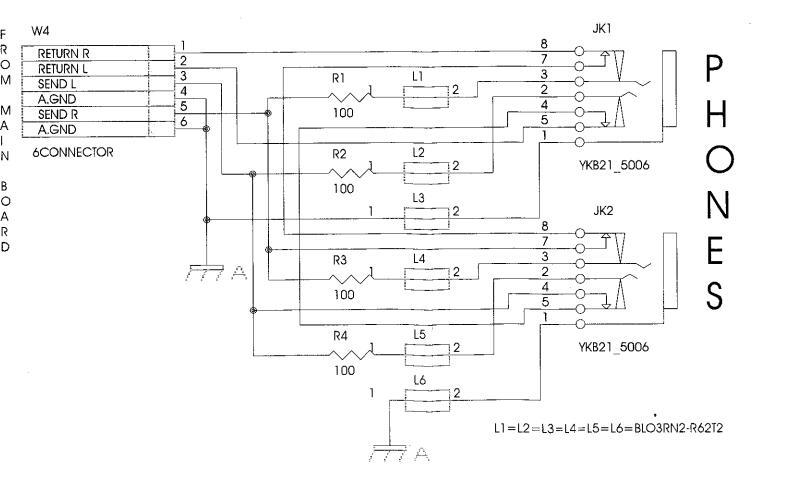
CIRCUIT DIAGRAM (HEADPHONES PCB ASSY)

PARTS LIST EP-85 (117V/230V/230VE/240VA)
| SAFETY I |
CONSIDERATION ON F
When ordering any parts listed in OTY PART |
PARTS ORDERING
the parts list,please specify the follo T NI IMBER |
owing items in the order sheet. | DIODE | 15129136 | TRANSISTOR | 2SC-2878-A/B | Q7/Q10 on MB | |
|---|---|---|---|---|---|---|---|---|---|
|
Use only
replaceme |
listed parts for
ent. |
Ex. 10 22
15 224 Failure to completely fill the abov even undelivered replacement. |
2575241 Sharp Ke
47017300 Knob (oran re items with correct number and des |
y C-20/50
ge) DAC-15D scription will result in delayed or |
15019159RI | DIODE | 1N-4148 |
All on CB, All on RCB,
All on LCB, D3/D9, D11 |
|
|
NOTE : Tr
<< EMI >> : RCB = Righ LCB = Left |
The parts marked "#" ar
The parts marked A Use only listed parts for : Component for EMC. ht Contact Board P Contact Board C |
e new (Initial Parts).
have Safety - Related characteristics. replacement. HB = Phones Board B = Control Board |
15339114
15029320RI 15029284RI J5019101 15019332RI J5019105 15091172BI |
DIODE
LED DIODE LED DIODE ZENER DIODE ZENER DIODE DIODE |
RB420D T146
TLHG4401 - GRE TLHR4401 - REE BZX79C 4V7 BZX79C 6.2V IN-4002 BY 251 |
on MB
D1 on PMB EEN D2,7,8,17, on CB All on CB D12, D13 on MB D2 on MB D1 on MB D10 on MB |
|||
| PMB = Piar | no Modole Board N | IB = Main Board | RESISTO | R | DIODE | BT 231 | DTO ON ME | ||
|
-ASING
# |
7698803000 | VARN+SILK. TOP CABINE | ET EP-85 | 15399917 | CHIP RES. ARRAY | 4X 10K E/U | RA8 on PMB | ||
|
#
# ASING |
7698804000
22195654KK K2238113 K2248125 |
VARNISHED BOTTOM CA
MUSIC REST MUSIC STOPPER GRILL F/LOUDSPEAKER |
NBINET EP-85 |
15399932
J3919104 13819132Ri 13819131Ri J3809129 J3809139 |
CHIP RES. ARRAY
CHIP RES.ARRAY UNINFL.RES. UNINFL.RES. UNINFL. RES. OXIDE RESISTOR |
4X100 E/U
2512 8X10 K +2C 100 OHM 0.6W 5 10 OHM 0.6W 5 220 OHM 0.6W 5 2.2 OHM 3W |
RA4 on PMB C RA1,2,3,5,6,7 on PMB 5% R2,3,4,5 on CB % R1 on CB 5% R51 on MB R21 on MB R21 on MB | ||
| # | 7698805000 | VARN+SILK. SOCKET SU | PPORT | POTENTI | OMETER | ||||
| HEADPHONES FIXING BA | ASE EP-/I | E |
13279884
13359364 |
ROT.POT.
SLIDER POT. |
10KB 90ø MONC
NNB-X10-B14 |
VR1 on MB
VR1 on CB |
|||
| K2478200 | BUTTON GROUP | 22X8+DIFFBLACK | CAPACIT | OR | |||||
|
#
# |
K2478201
K2478203 K2478252 K2478253 22488183 22485192 |
BUTTON GROUP
BUTTON GROUP 4-BUTTON GROUP+DIF 4-BUTTON GROUP+DIFF. POWER SWITCH KNOB N BLACK KNOB W/WHITE IN |
15X8 +DIFF.(BLACK)
(4) 15X8 -BLACK- 22X8 (GREY) 15X8(RED) 1.001-BLACK NDICATOR |
J3519117
13529147RI J3629144 13649668RI 13639154 J3629134 13639651RI |
CERAM.COND.
CAPAC.ARRAY ELCTRL.COND. ELECTRL.CONDY ELECTRL.CONDY ELECTRL.CONDY |
4.7N 25V 20%
8X100 PF 470UF 16V AX 47UF 25V / 1000UF 16V / 2200UF 16V / 2200UF 26V |
C39 on MB
CA1 on MB C4 on CB C5 on CB C24, C27 on MB C5, C9 on MB C1 on MB |
||
| WITCH | 1312975301 | R 160 All on | 13649662RI | ELECTRL.CONDV | / 3300UF 25V | C58 on MB | |||
| 13129135 | SWITCH SDDWA-1401A | SW2 | on MB | J3629103 | ELECTROL.COND. | 22U 25V P5 |
C2,23,26,29,35 01 MB
C4, C8 on MB C6 10 22 44 56 57 60 61 on MP |
||
| ACK, SO | CKET | Tele March March |
J3629104
J3629105 |
ELECTRL.COND. | 47U 50V P5 | C3,7,10,26,30,32 on MB | |||
|
13449726
13449252 13449125 13429664RI |
DC SUPPLY SOCKET F
JACK SOCKET Y JACK SOCKET F DIN SOCKET M |
HEC 2305-01-230 JK2 c
YKB 21-5006 JK1, c HLJ0520-01-110 JK5/J MG/PR 5L JK3, c |
n MB
JK2 on PHB K10 on MB JK4 on MB |
J3629106
J3629107 J5369101 13649103J0 13659306 |
ELECTRL.COND.
ELECTRL.COND. ELECTR. COND. UNPOL.COND. SPEC. COND. |
4.70 637 F5
1UF 100V P5 22U 16V (SMD) 10U 16 P5 0.047F 5.5V BAD |
C20,21,31 on MB
C22,43,45,48,49,50,80,81 on MB C12,13,14,15,55 on PMB C71,72,74,75,77,78 on MB C57 on PMB |
||
| PEAKER | INDUCTO | R, COIL, FILTER | |||||||
| K2418103 | SPEAKER 4 OHM 120.20B | 3/FX |
<
|
12449370 | NOISE SUP. | SBT-0160W | L3, L8, L9, L11 on MB | ||
| EYBOAR | 7608008000 |
<
|
13529187 | NOISE SUP. | ELKTR391CA | FL1,FL3/FL9 on MB | |||
|
#
`B 499V |
NOTE :For detail | s, refer to KEYBOARD PART | TS LIST (Pag.4) |
<
< < |
12449382
12449380 J2399101 |
NOISE SUP.
NOISE SUP. NOISE SUP. |
EXC-ELDR25V
BL03RN2-R62T2 |
L1 on MB
L2, FL2, L7,L10,L12/L15 on MB L1/L6 on PHB |
|
| 70 A001 | 7695902000 | HEADPHONES PCB ASSY | 1 | CRYSTAL | , RESONATOR | ||||
|
#
E # |
7698802000
7698801001 |
CONTROLS PCB ASSY
MAIN BOARD PCB ASSY |
EP-85
EP-85 |
5 | 15299180 | QUARTZ | 24 MHZ | X1 on PMB | |
|
#
# |
7698903000
7698904000 |
RIGHT CONTACT PCB ASS
LEFT CONTACT PCB ASS |
SY W/RUBBER
Y W/RUBBER |
CONNEC | 13419677BI | ||||
| # # |
15229718RI
K525813210 K525813010 K525813410 |
I.C. 6N 137
I.C. K525813210 I.C. K525813010 I.C. HD6435328RW21F |
PHOTO-COUPLER
MASK ROM MASK ROM FLAT |
IC6 on MB
IC6 on PMB IC7 on PMB IC3 on PMB |
133696888RI
133696888RI J3439103 J3439117 J3439120 |
20P FEM. CON
4P MALE CON 6P MALE CON 6P MALE CON 4P MALE CON |
NECTOR AMP 1.27
NN. P 2.5 M NN. P 2.5 M NN. 900 P. 2.5 NN. 92 M |
CN2,CN3 on PMB, CN1 on
RCB, CN1 on LCB CN1 on MB CN3 on MB CN2 on CB CN2 on RCB, CN2 on LCB |
|
|
15169550RI
15259886 |
I.C. 74 HC138
I.C. 74 HCU 04 |
DIP CMOS
CMOS SMD |
IC3 on CB
IC1 on PMB |
J3439121 | 6P MALE CON | IN. P.2 M | CN4 on MB, W4 on PHB | ||
|
00129278
J5259110 |
I.C. SSC1080 FOB | (CUSTOM IC) | IC11 on PMB | WIRING, O | CABLE | ||||
|
15239229
15259884 15259883 15259887 15219183 15199559RI 15199560RI 15189251 |
I.C. TC6116-GP4
I.C. TC7S08F MOS I.C. TC7S00F TE85L I.C. TC7SU04F FLAT I.C. M51953 A STANDING I.C. TD 62506P I.C. TD62305AP I.C. M5218 P |
(CUSTOM IC)
CMOS CMOS CMOS (RESET IC) (INTERF.DRIVER IC) (INTERF.DRIVER IC) (OP AMP) |
IC4 on PMB
IC5 on PMB IC12 on PMB IC13 on PMB IC4 on MB IC1 on CB IC2 on CB IC2 on MB |
# |
7698907000
7698905000 7695908000 K3468160 K3468161 K3468162 |
4P CABLE ASSY
2P COAXIAL CBL A 6-CBL ASSY 4P CABLE ASSY 20P FLAT CABLE 20P FLAT CABLE |
(6) -2C P.2
(56) -2C (28/106) (W/4PC) (36) -2C (56) -2C |
CN2 on RCB to CN2 on
LCB CN3 on MB to CN2 on CB CN4 on MB to W4 on PHB CN1 on MB to Speaker CN3 on PMB to CN1 on RCB CN2 on PMB to CN1 on |
|
|
15289702
15199197RI 15199550RI |
I.C. UPD6376
I.C. UA 7805 SCNC I.C. TDA 1905 |
DAC
REGUL.(+5V) (POWER AMP) |
IC3 on MB
IC5 on MB IC1,IC2 on MB |
000514 | 7627102001 | 16P FLAT CBL | (42) W(16PC- - |
LCB
16PC) CN2 on MB to CN1 on CB |
|
| ANSIST | OR | (, , | SCREW | J2289122 | SELF TAP.SCREW | 2 2X 6 TC TC | |||
|
15119155RI
J5119101 15119154RI |
TRANSISTOR
TRANSISTOR TRANSISTOR |
BC/560-B
BD 371 C BC/549-B |
Q1 on CB, Q4,13 on MB
Q3 on MB Q1,2,5,6,11,12 on MB |
J2289121
J2289125 J2289130 |
SELF TAP. SCR.
SCREW SCREW |
2.2X10 C.C
2.9X10 TC TC PF 2.9X10 TC TC PF |
R TROP
R TROP |
| 1 | DAOKING |
J2289128
J2289108 J2289109 J2289115 J2289112 J2289113 J2139102 K2168102 J2359101 |
SELF TAP.SCREW
SELF LOCK.SCREW SELF LOCK.SCREW SPEC.SCREW NUT TOOTHED WASHER SPACER FOR LED SPACER 3M |
3.5X19 TCTCPF
M3X10 TCTC H M4X14 TCTC H, 3.5X9.5 TCPRTF 3.5X12 TCTC TS 3MA H.3 I/D 3 H.2.8 D.E. 5.5 ART. SJ5012 |
BZ
.6 9.5 R H.8 |
|
|---|---|---|---|---|---|---|
| PACKING | ||||||
| # |
K2638169
K2638170 K2678116 K2618178 |
RIGHT POLYST. END-SIDE
LEFT POLYST. END-SIDE CARTENE ENVELOPE OUTER PACKING |
HD 70X190 |
EP-85
EP-85 EP-85 |
||
| MISCELL | ANEOUS | |||||
| # |
22248470
K2268128 K3468138 1342982301 K2238117 K2268145 |
ANTI-DUST COVER
RED FELT COPPER STRIP POWER SUPPLY SOCKET OVAL DIFFUSER VIBRATION DAMPER |
HOLDER Nø 2 |
PL30N
MM. 1250X7X1 0.2X20X70 MM. 2H. F/4 LINEAR LEDS W300N (BLACK) |
||
| ACCESSO | DRIES | |||||
|
#
# |
K6018109
K6018264 K6018265 J3059103 22448612 2244861101 2244861001 |
MIDI GUIDE
OWNER'S MANUAL (I/SP/E OWNER'S MANUAL (E/D/F DP-6 FOOTSWITCH PEDA POWER ADAPTORACJ 120 POWER ADAPTORACJ 230 POWER ADAPTORACJ 230 |
DUTCH)
) L (PEDAL W/CAB )V DV DVE |
EP85/95
EP85/95 LE) (117V) (230V) (230VE) |
||
| ⊿∆ | 22448614 | POWER ADAPTORACJ 240 | )VA | (240VA) |
IDENTIFYING THE SOFTWARE VERSION
Press "E Piano 3" while switching ON the instrument.
| • • | 0 0 | 0 • | ••• | Soft.Ver.=1.00 |
|---|---|---|---|---|
| 00 | • • | ● ● | ••• | Soft.Ver.=1.01 |
| • • | 00 | • | ••• | Soft.Ver.=1.02 |
| • • | • | • | •• | Soft.Ver.=1.03 |
The software version will be indicated by the tone leds on the control panel as shown above. To exit, switch the power off.
TEST MODE
Switch the instrument on while holding down the "Piano 1" button. In the model EP-85, the "Pop" button led turns on.
The leds of all the tone buttons blink until one the following possible checks is selected.
The TEST MODE includes 9 tests:
| 1) Piano1 | Test Switch +Led |
|---|---|
| 2) Piano 2 | Test Pedal (or Audio test if pressed while switching on the imstrument). |
| 3) E.Pia.1 | Test Keyboard |
| 4) Vibr. | Midi |
| 5) Harp. | Ram |
| 6) Organ | W Rom |
| 7) String | Rom Program |
| 8) Choir | Adc |
| 9) Effect | Reverb |
| Chorus |
To exit, press the "Start" and "Choir" buttons simultaneously.
1) Switch and Led test
Press the "Piano1" button and all leds turn on.
When pressing each single button, you can hear a metronome beat while the corresponding button led lights. When pressing the buttons whithout leds, like TEMPO +/- and VOLUME +/-, the beat leds will turn on from left to right depending on the button you' ve pressed. Once all leds turn off, after checking all the corresponding buttons, the test is completed. You cannot exit this test mode before completing this check.
To exit press "Start" + "Choir" buttons simultaneously
2) Pedal test
Press "Piano2", connect the "Soft" and "Damper" pedals to the instrument.
When pressing the "Soft" pedal you'll hear a sound and the first led on the left of the tempo indicator will turn on.
When pressing the "Damper" pedal you'll hear a sound and the last led on the right of the tempo indicator will turn on.
To exit press "Start" + "Choir" buttons simultaneously
3) Keyboard test
Press the "E.Piano" button.
When pressing a key, a sound is generated; the key velocity level is shown by the leds on the control panel, since they turn on in sequence one after another depending on the velocity level, starting from level 1 (= the led on the "Piano" button turns on), up to 127, the highest level (= the "Choir" led turns on)
To exit press "Start" + "Choir" buttons simultaneously
4) Midi test
Press the "Vibraphone" button.
Shortcircuit the Midi IN/OUT sockets on the rear panel by using a MIDI CABLE.
- If the "Play" button led lights, it's OK.
- If the "Rec" button led lights, there's an ERROR.
- The error cause, is: either a wrong transmission/reception, or that the MIDI CABLE was not connected correctly.
To exit press "Start" + "Choir" buttons simultaneously
5) Ram test (IC2 on Piano Module)
Press the "Harpsichord" button.
- If the "Play" button led lights, it's OK.
- If the "Rec" button led lights, there's an ERROR.
- The error cause, is: something wrong either in the RAM (IC2 on Piano Module), or in the circuit.
To exit press "Start" + "Choir" buttons simultaneously
6) Wave Masked Rom test (IC7 on Piano Module)
Press the "Organ" button.
- If the "Play" button led lights, it's OK.
- If the "Rec" button led lights, there's an ERROR.
The error cause, is: something wrong either in the WAVE ROM (IC7 on Piano Module), or in the cir cuit.
To exit press "Start" + "Choir" buttons simultaneously
7) Programmed Masked Rom test (IC6 on Piano Module)
Press the "Strings" button.
- If the "Play" button led lights, it's OK.
- If the "Rec" button led lights, there's an ERROR.
- The error cause, is: something wrong either in the PROGRAMMED ROM (IC6 on Piano Module), or in the circuit.
To exit press "Start" + "Choir" buttons simultaneously
8) Adc test
Press the "Choir" button to enter the Adc test mode (Tune/Volume)
MASTER TUNE TEST
The "Piano1" and "Piano2" buttons blink, press "Piano1" and its led will light while the "Piano2" led turns off.
- When closing the "TUNE " potentiometer towards the " b " symbol, a falling sound can be heard; - when opening the "TUNE " potentiometer toward the " # " symbol, an increasing sound can be heard Each end position is signalled by a metronome beat.
To exit press "Start" + "Choir" buttons simultaneously
MASTER VOLUME TEST
When moving this potentiometer from "MAX" to "MIN", the general volume dicreases till no sound can be heard.
When moving the potentiometer from "MIN" to "MAX", the general volume reaches its highest level.
To exit press "Start" + "Choir" buttons simultaneously.
9) Effect test (IC8 on Piano Module)
Press the "Chorus" button, you'll hear a sound with the chorus effect. Press "Reverb", you'll heard a bassdrum tone and the metronome beats with reverb effect.
To exit press "Start" + "Choir" buttons simultaneously.
Audio test
Switch the instrument on while keeping the "Piano2" button pressed. You'll hear a hight frequency sound from the left speaker and a low frequency sound from the right speaker.
To exit, switch the instrument off.
Factory Setup
After finishing the checks, switch the instrument on while keeping the "REC" button pressed.
Both the "REC" and "PLAY" leds blink for a few seconds, this confirms the program has been reset.


 Loading...