

Page 1
USER'S MANUAL
➢ To ensure safe usage and full performance of this product, please be sure to read through this
manual completely.
➢ To ensure immediate access whenever needed, store this manual in a safe location.
➢ Unauthorized copying, quotation, or translation of this manual, in whole or in part, without the
written approval of Roland DG Corp., is prohibited.
➢ The contents of this document and the specifications of this product are subject to c hange without
notice.
➢ Roland DG Corp. assumes no responsibility for any loss or damage relating to this product, regard-
less of any defect in this product or this manual. Such loss or damage, whether direct or indirect,
includes, but is not limited to, that arising from the specifications or performance of this product,
that due to failure of the product to perform, and that arising from any article made using this
product.
Page 2

For the USA
FEDERAL COMMUNICATIONS COMMISSION
RADIO FREQUENCY INTERFERENCE
STATEMENT
This equipment has been tested and found to comply with the
limits for a Class A digital device, pursuant to Part 15 of the
FCC Rules.
These limits are designed to provide reasonable protection
against harmful interference when the equipment is operated
in a commercial environment.
This equipment generates, uses, and can radiate radio
frequency energy and, if not installed and used in accordance
with the instruction manual, may cause harmful interference
to radio communications.
Operation of this equipment in a residential area is likely to
cause harmful interference in which case the user will be
required to correct the interference at his own expense.
Unauthorized changes or modification to this system can void
the users authority to operate this equipment.
The I/O cables between this equipment and the computing
device must be shielded.
For Canada
CLASS A NOTICE
This Class A digital apparatus meets all requirements of the
Canadian Interference-Causing Equipment Regulations.
NOTICE
Grounding Instructions
Do not modify the plug provided - if it will not fit the outlet, have
the proper outlet installed by a qualified electrician.
Check with qualified electrician or service personnel if the
grounding instructions are not completely understood, or if in
doubt as to whether the tool is properly grounded.
Use only 3-wire extension cords that have 3-prong grounding
plugs and 3-pole receptacles that accept the tool’s plug.
Repair or replace damaged or worn out cord immediately.
Operating Instructions
KEEP WORK AREA CLEAN. Cluttered areas and benches
invites accidents.
DON’T USE IN DANGEROUS ENVIRONMENT. Don’t use
power tools in damp or wet locations, or expose them to rain.
Keep work area well lighted.
DISCONNECT TOOLS before servicing; when changing
accessories, such as blades, bits, cutters, and like.
REDUCE THE RISK OF UNINTENTIONAL STARTING.
Make sure the switch is in off position before plugging in.
USE RECOMMENDED ACCESSORIES. Consult the owner’s
manual for recommended accessories. The use of improper
accessories may cause risk of injury to persons.
NEVER LEAVE TOOL RUNNING UNATTENDED. TURN
POWER OFF. Don’t leave tool until it comes to a complete
stop.
CLASSE A AVIS
Cet appareil numérique de la classe A respecte toutes les
exigences du Règlement sur le matériel brouilleur du
Canada.
WARNING
This is a Class A product. In a domestic environment this product may cause radio interference in which
case the user may be required to take adequate measures.
Page 3

Contents
To Ensure Safe Use .......................................................................................................................4
Pour utiliser en toute sécurité ..................................................................................................11
Important Notes on Handling and Use ...........................................................................................18
About the Documentation for This Machine...................................................................................19
Chapter 1 Getting Started ..............................................................................................................21
1-1 Machine Highlights ............................................................................................................................................. 22
Features ......................................................................................................................................... 22
1-2 Part Names and Functions ...............................................................................................................................23
Front and Interior........................................................................................................................... 23
Side ............................................................................................................................................... 24
Chapter 2 Installation and Setup....................................................................................................25
2-1 Checking the Included Items ...........................................................................................................................26
2-2 Installation ............................................................................................................................................................27
About Emplacement and Installation............................................................................................. 27
Installation Environment................................................................................................................ 27
Unpacking..................................................................................................................................... 29
2-3 Cable Connections............................................................................................................................................. 30
Connecting the Handy Panel ......................................................................................................... 30
Connecting the Power Cord .......................................................................................................... 31
Connecting a Computer Via a Communication Cable ................................................................... 32
2-4 Selecting the Language ...................................................................................................................................... 33
Selecting the Language Used for Text on the Display Screen......................................................... 33
2-5 Before Starting Operations..............................................................................................................................35
Spindle Run-in (Warm-up)............................................................................................................. 35
Chapter 3 Basic Operation...............................................................................................................37
3-1 Types of Emergency Stops to Ensure Safety.................................................................................................38
How to Perform an Emergency Stop.............................................................................................. 38
To Cancel an Emergency Stop ....................................................................................................... 38
Emergency Stop Due to Opening or Closing the Front Cover........................................................ 39
3-2 Starting and Quitting ......................................................................................................................................... 40
How to Start the Machine.............................................................................................................. 40
Shutdown ...................................................................................................................................... 41
3-3 Using the Handy Panel ...................................................................................................................................... 42
3-4 Moving the Cutter.............................................................................................................................................. 43
Terms Indicating the Cutter Position.............................................................................................. 43
Viewing the Cutter Position........................................................................................................... 43
Manual Movement ........................................................................................................................ 44
Moving to a Specific Position Automatically ................................................................................. 45
3-5 Spindle Operation .............................................................................................................................................. 47
Starting and Stopping Spindle Rotation ......................................................................................... 47
Adjusting the Spindle Speed.......................................................................................................... 48
3-6 Pausing and Stopping Cutting ..........................................................................................................................49
Pausing and Resuming Cutting ...................................................................................................... 49
Stopping Cutting............................................................................................................................ 50
Chapter 4 Engraving..........................................................................................................................51
4-1 Flow of Engraving Operations......................................................................................................................... 52
4-2 Mounting a Workpiece...................................................................................................................................... 54
1
Page 4

Contents
4-3 Selection of the Cutter (Usage Examples)................................................................................................... 55
4-4 Cutter Installation Method 1 (With Nose Unit) ........................................................................................ 56
Installing a Character Cutter (With Nose Unit) .............................................................................. 5 6
Important Notes When Using the Nose Unit................................................................................. 61
4-5 Cutter Installation Method 2 (No Nose Unit)............................................................................................ 62
Installing a Character Cutter (With No Nose Unit) ........................................................................ 62
4-6 Cutter Installation Method 3 (Diamond Scraper)...................................................................................... 67
Installing a Diamond Scraper ........................................................................................................ 67
4-7 Cutter Installation Method 4 (End mill)........................................................................................................ 71
Installing a End Mill....................................................................................................................... 71
4-8 Setting the XY Origin Point............................................................................................................................. 75
Setting the XY Origin Point (Home Position) ................................................................................. 75
4-9 Performing Engraving......................................................................................................................................... 76
Performing Engraving .................................................................................................................... 76
Adjusting the Cutter Feed Rate During Engraving (Override)......................................................... 77
Executing Repeated Cutting........................................................................................................... 78
Chapter 5 Feature reference............................................................................................................79
5-1 Attaching the Vacuum Adapter for Chip Cleaning ...................................................................................... 80
Using the Vacuum Adapter ............................................................................................................ 80
5-2 The Position of the Lock Lever .......................................................................................................................82
5-3 Surface Leveling of the Workpiece Table ...................................................................................................... 83
5-4 Menu List ..............................................................................................................................................................84
Main Menu.................................................................................................................................... 84
Submenus...................................................................................................................................... 85
Origin-setting Menu ...................................................................................................................... 86
Pause Menu ................................................................................................................................... 86
Copy Menu.................................................................................................................................... 87
5-5 Description of Menu Items ..............................................................................................................................88
Main Menu.................................................................................................................................... 88
I/O Menu (Submenu)..................................................................................................................... 89
Others Menu (Submenu) ............................................................................................................... 90
Adjustment Menu (Submenu) ........................................................................................................ 91
Origin-setting Menu ...................................................................................................................... 92
Pause Menu ................................................................................................................................... 93
Copy Menu.................................................................................................................................... 93
Chapter 6 Maintenance ....................................................................................................................95
6-1 Daily Care............................................................................................................................................................. 96
Cleaning ........................................................................................................................................ 96
Cleaning Inside the Front Cover .................................................................................................... 96
Cleaning Around the Spindle ........................................................................................................ 97
6-2 Maintenance and Inspection............................................................................................................................. 98
Spindle Maintenance..................................................................................................................... 98
Chapter 7 Troubleshooting ..............................................................................................................99
7-1 Troubleshooting (Engraving)...........................................................................................................................100
The cutting-in depth is not uniform (when using the nose unit)................................................... 100
The cutting-in depth is not uniform (when not using the nose unit). ........................................... 100
The cutter leaves tracks at places where cutting-in starts or where lines change direction.......... 100
An engraved bottom surface is rough or burring remains............................................................ 100
Engraved lines are uneven or wavy.............................................................................................. 100
7-2 Troubleshooting (Operation) .........................................................................................................................101
The power does not come on...................................................................................................... 101
Initialization is not performed or initialization fails..................................................................... 101
2
Page 5

Contents
Operations are ignored................................................................................................................ 101
Abnormal cutting is performed.................................................................................................... 101
The spindle doesn’t rotate during engraving. ............................................................................... 101
Descent doesn’t stop (when automatic Z control is on)............................................................... 101
The USB cable came loose during engraving. ............................................................................. 102
7-3 Responding to a Message ...............................................................................................................................103
7-4 Responding to an Error Message..................................................................................................................104
Chapter 8 Appendix ........................................................................................................................107
8-1 Examples of Settings for Cutting Parameters............................................................................................108
Example Settings ......................................................................................................................... 108
Tips for Fine-tuning ..................................................................................................................... 108
8-2 Location of Power Rating and Serial Number Label................................................................................109
8-3 Interface Specifications.................................................................................................................................... 110
Serial Connector.......................................................................................................................... 110
Expansion Connector .................................................................................................................. 111
8-4 Main Unit Specification....................................................................................................................................112
Dimensions of Outline ................................................................................................................ 112
Work area.................................................................................................................................... 113
Workpiece-table Installation-area Dimensional Drawing............................................................ 114
Main Specifications ..................................................................................................................... 115
System Requirements for USB Connection.................................................................................. 115
Company names and product names are trademarks or registered trademarks of their respective holders.
http://www.rolanddg.co.jp/Copyright © 2007 Roland DG Corporation
3
Page 6
To Ensur e Safe Use
Improper handling or operation of this machine may result in injury or damage to property. Points which
must be observed to prevent such injury or damage are described as follows.
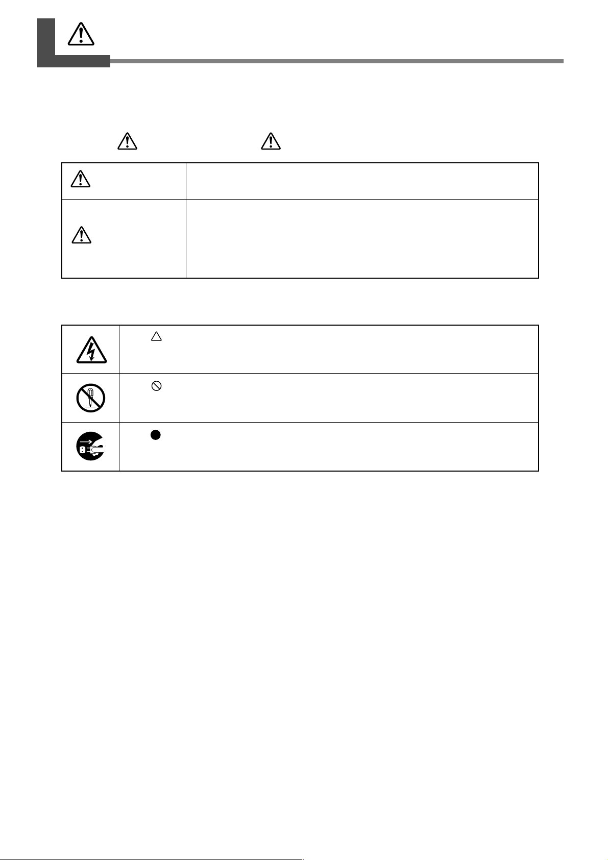
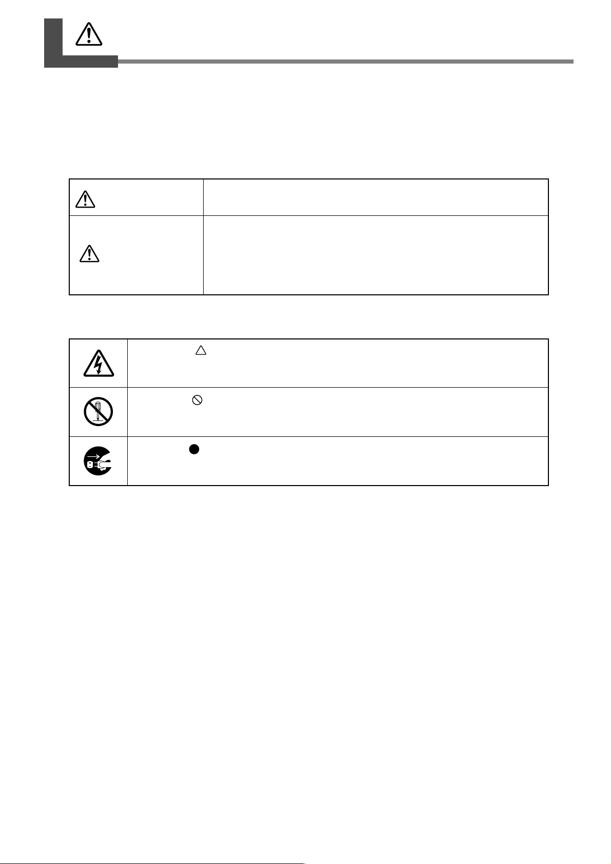
About WARNING and CAUTION Notices
WARNING
CAUTION
Used for instructions intended to alert the user to the risk of death or severe
injury should the unit be used improperly.
Used for instructions intended to alert the user to the risk of injury or material
damage should the unit be used improperly.
Note: Material damage refers to damage or other adverse eff ects caused with
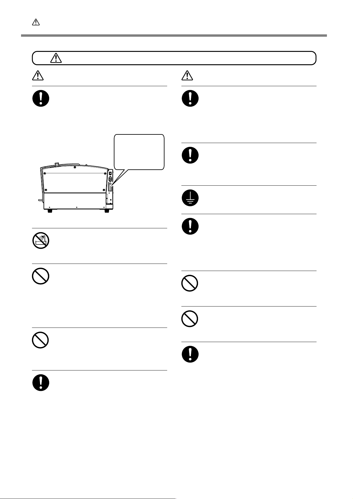
About the Symbols
The symbol alerts the user to important instructions or warnings. The specific meaning of
the symbol is determined by the design contained within the triangle. The symbol at left means
"danger of electrocution."
The symbol alerts the user to items that must never be carried out (are forbidden). The
specific thing that must not be done is indicated by the design contained within the circle. The
symbol at left means the unit must never be disassembled.
The symbol alerts the user to things that must be carried out. The specific thing that must be
done is indicated by the design contained within the circle. The symbol at left means the pow er cord plug must be unplugged from the outlet.
respect to the home and all its furnishings, as well to domestic animals
or pets.
4
Page 7
To Ensure Safe Use
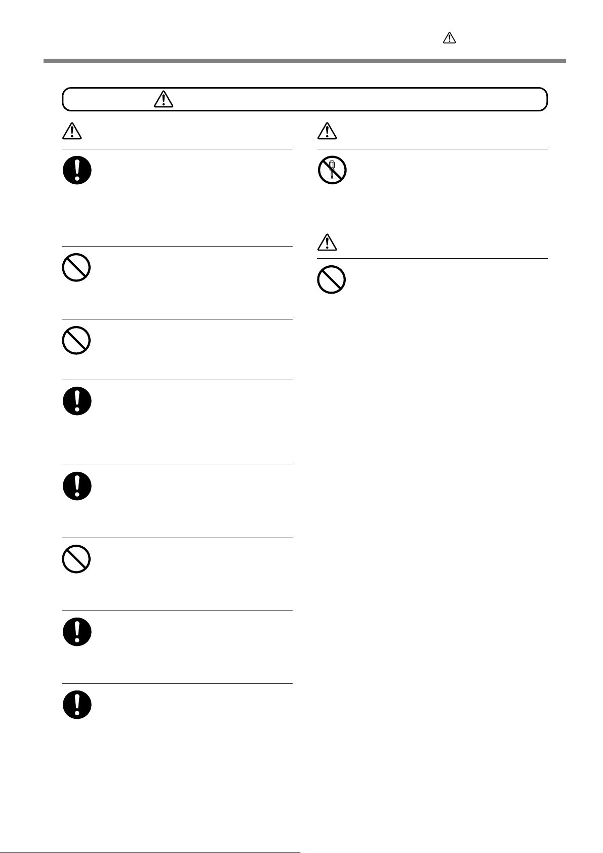
Incorrect operation may cause injury.
WARNING
Be sure to follow the operation procedures described in this documentation.
Never allow anyone unfamiliar with the
usage or handling of the machine to touch
it.
Incorrect usage or handling ma y lead to an accident.
Keep children awa y fr om the machine.
The machine includes areas and components
that pose a hazard to children and ma y result in
injury, blindness, choking, or other serious accident.
Never operate the machine while tir ed or
after ingesting alcohol or any medication.
Operation requires unimpaired judgment. Impaired judgment may result in an accident.
Conduct operations in a clean, brightly lit
location.
Working in a location that is dark or cluttered
may lead to an accident, such as becoming caught
in the machine as the result of an inadvertent
stumble.
WARNING
Never attempt to disassemble, repair, or
modify the machine.
Doing so may result in fire, electrical shock, or
injury. Entrust repairs to a trained service technician.
CAUTION
Never climb or lean on the machine.
The machine is not made to support a person.
Climbing or leaning on the machine may dislodge components and cause a slip or fall, resulting in injury.
Never use the machine for any purpose
for which it is not intended, or use the
machine in an undue manner that exceeds
its capacity .
Doing so may result in injury or fire.
Never use a cutting tool that has become
dull. Perform frequent maintenance to
keep and use the machine in good working order.
Unreasonable usage may r esult in fire or injury.
For accessories (optional and consumable
items, power cord, and the like), use only
genuine articles compatible with this machine.
Incompatible items may lead to an accident.
Before attempting cleaning, maintenance,
or attachment or detachment of optional
items, disconnect the power cord.
Attempting such operations while the machine
is connected to a power source may result in
injury or electrical shock.
5
Page 8
To Ensure Safe Use
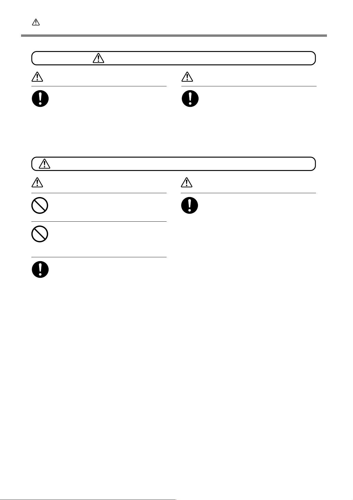
This machine weighs 34 kg (75 lb .)
The cutting waste or workpiece may catch fire or pose a health hazard.
CAUTION
Unloading and emplacement are operations that must be performed by 2 persons or more.
T asks that r equire undue effort when performed
by a small number of persons may r esult in physical injury. Also , if dropped, such items ma y cause
injury.
WARNING
Never attempt to cut magnesium or any
other such flammable material.
Fire may occur during cutting.
Keep open flame a wa y from the work area.
Cutting waste may ignite. Powdered material is
extremely flammable, and even metal material
may catch fire.
CAUTION
Install in a location that is level and stab le.
Installation in an unsuitable location may cause
an accident, including a fall or tipover.
CAUTION
W ear dust goggles and a mask. W ash a way
any cutting waste remaining on the hands.
Accidentally swallowing or inhaling cutting waste
may be hazardous to the health.
When using a vacuum cleaner to take up
cutting waste, exer cise caution to pre vent
fire or dust explosion.
T aking up fine cuttings using an or dinary vacuum
cleaner may cause danger of fire or explosion.
Check with the manufacturer of the vacuum
cleaner. When the safety of use cannot be determined, clean using a brush or the like, without using the vacuum cleaner.
6
Page 9

To Ensure Safe Use
Danger of pinching, entanglement, and burns.
WARNING
Never attempt operation while w earing a
necktie, necklace, loose clothing, or glo ves.
Bind long hair securely.
Such items may become caught in the machine,
resulting in injury .
Securely fasten the cutting tool and workpiece in place. After securing in place,
make sure no wrenches or other articles
have inadv ertently been left behind.
Otherwise such articles may be thrown from
the machine with force, posing a risk of injury.
Exercise caution to avoid being pinched
or becoming caught.
Inadvertent contact with certain areas may cause
the hand or fingers to be pinched or become
caught. Use care when performing operations.
WARNING
Caution: cutting tool.
The cutting tool is sharp. To avoid injury, exercise caution.
Caution: high temperatur es.
The cutting tool and spindle motor become hot.
Exercise caution to avoid fire or burns.
7
Page 10
To Ensure Safe Use
Danger of electrical short, shock, electrocution, or fire
WARNING
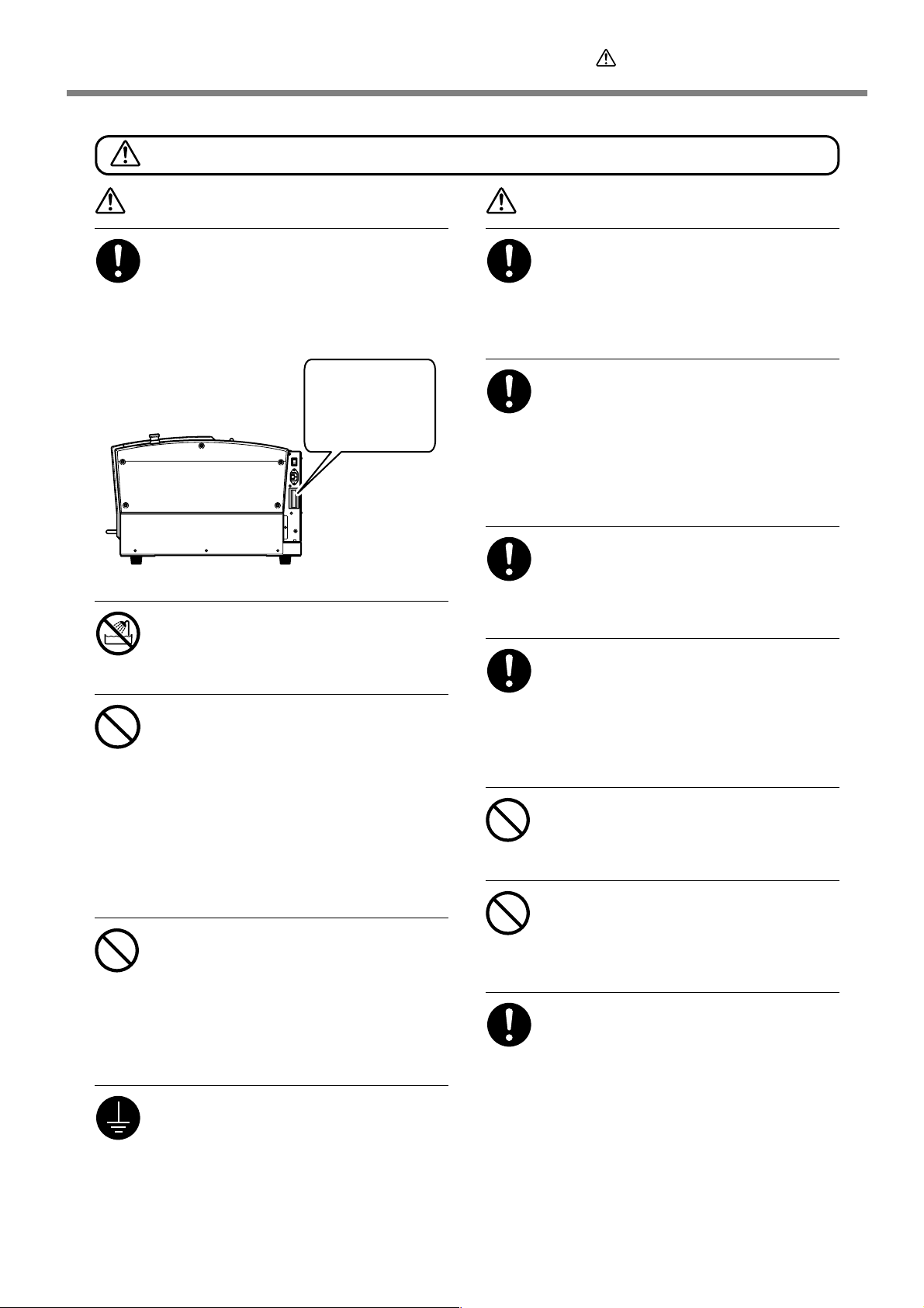
Connect to an electrical outlet that complies with this machine’ s ratings (f or voltage, frequency, and current).
Incorrect voltage or insufficient current may
cause fire or electrical shock.
Ratings
Never use out of doors or in any location
where exposure to water or high humidity may occur . Never touch with wet hands.
Doing so may result in fire or electrical shock.
Never allow any foreign object to get inside. Never expose to liquid spills.
Inserting objects such as coins or matches or
allowing beverages to be spilled into the ventilation ports may result in fire or electrical shock.
If anything gets inside, immediately disconnect
the power cord and contact your authorized
Roland DG Corp. dealer.
Never place an y flammable object nearby .
Never use a combustible aerosol spray
nearby. Never use in any location where
gases can accumulate.
Combustion or explosion may be a danger.
Handle the power cord, plug, and electrical outlet correctly and with care. Never
use any article that is damaged.
Using a damaged article may result in fire or
electrical shock.
WARNING
When using an extension cord or power
strip, use one that adequately satisfies the
machine’s ratings (for voltage, frequency,
and current).
Use of multiple electrical loads on a single electrical outlet or of a lengthy extension cord may
cause fire.
When the machine will be out of use for a
prolonged period, disconnect the power
cord.
This can prevent accidents in the event of current leakage or unintended startup.
Connect to ground.
This can prevent fir e or electrical shock due to
current leakage in the event of malfunction.
Position so that the power plug is within
immediate reach at all times.
This is to enable quick disconnection of the
power plug in the event of an emergency. Install
the machine next to an electrical outlet. Also,
provide enough empty space to allow immediate access to the electrical outlet.
Never use cutting oil.
This machine is not designed for the flow of
cutting oil. Oil may get inside the machine and
cause fire or electrical shock.
Never use a pneumatic blower.
This machine is not compatible with a pneumatic
blower. Cutting waste may get inside the machine and cause fire or electrical shock.
If sparking, smoke, burning odor, unusual
sound, or abnormal operation occurs, immediately unplug the power cord. Never
use if any component is damaged.
Continuing to use the machine may r esult in fire,
electrical shock, or injury. Contact your authorized Roland DG Corp. dealer.
8
Page 11
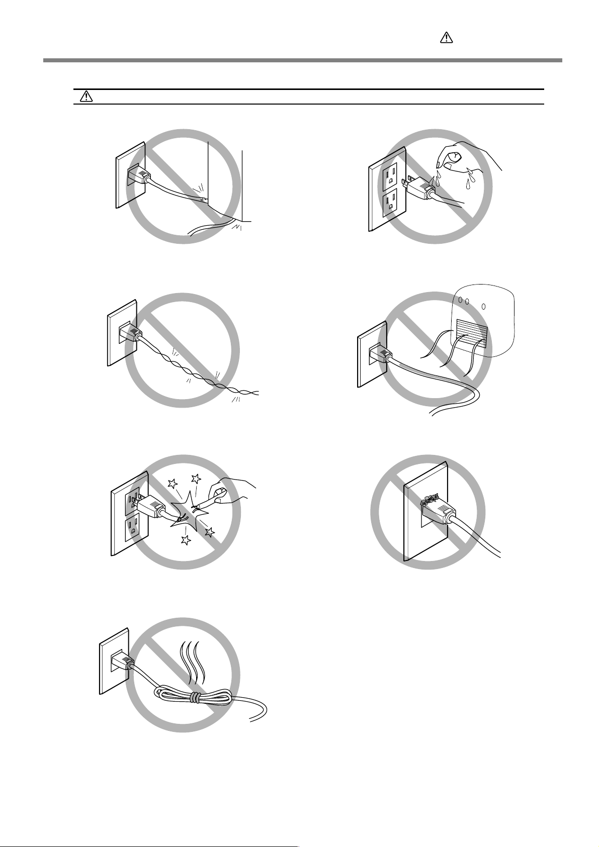
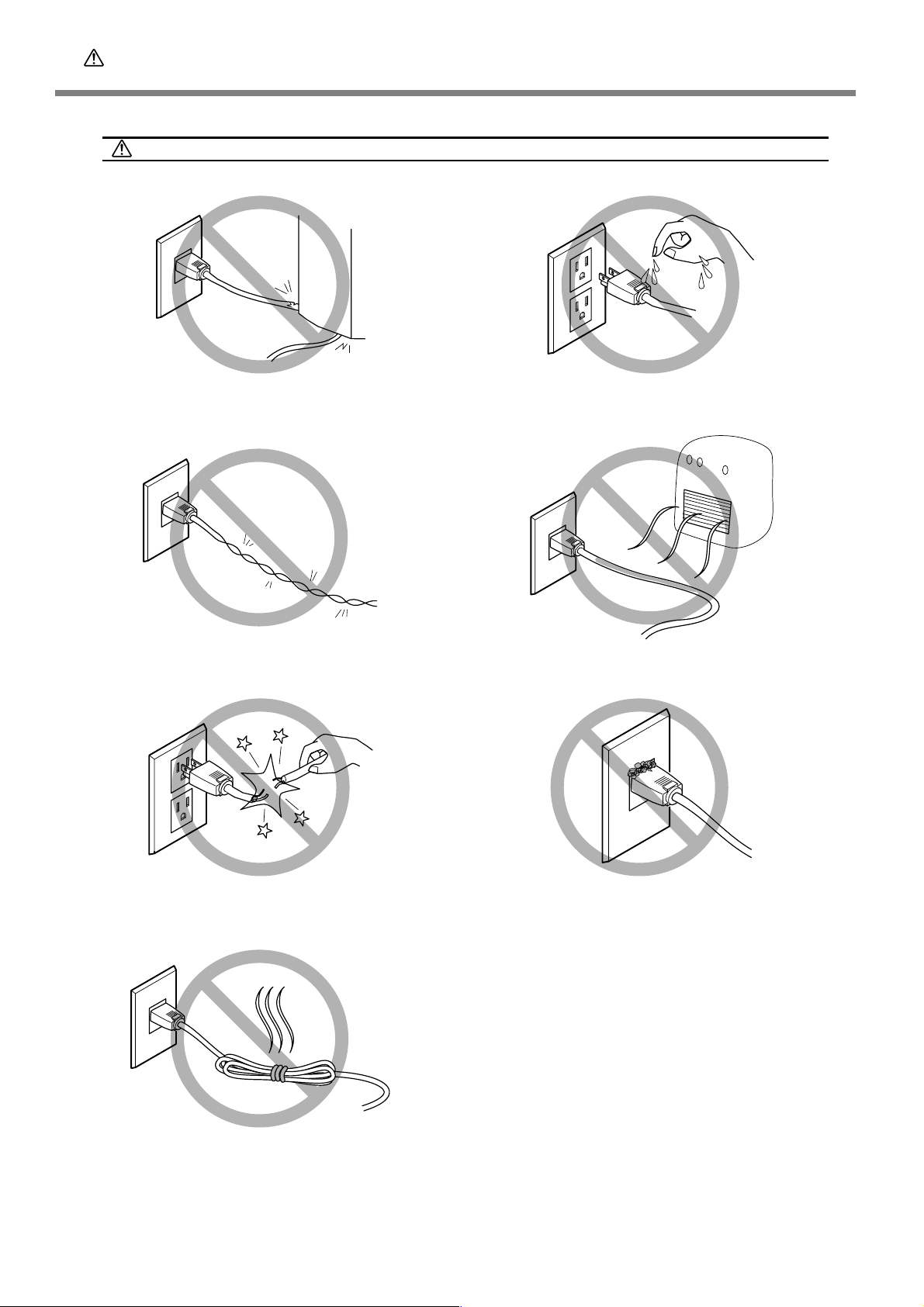
Important notes about the power cord, plug, and electrical outlet
To Ensure Safe Use
Never place any object on top or subject to
damage.
Never bend or twist with undue force.
Never allow to get wet.
Never make hot.
Never pull with undue force.
Never bundle, bind, or roll up.
Dust may cause fire.
9
Page 12
To Ensure Safe Use
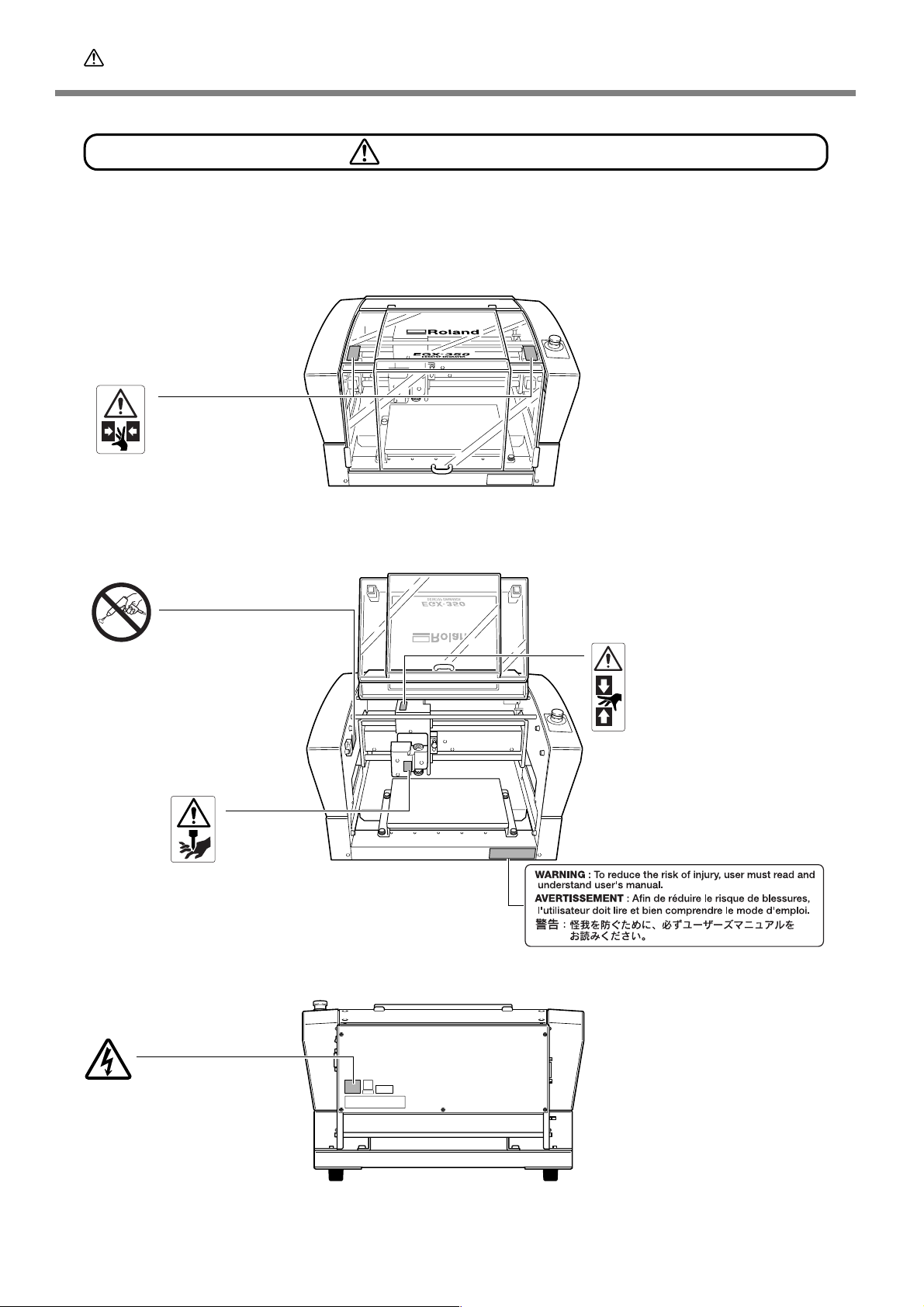
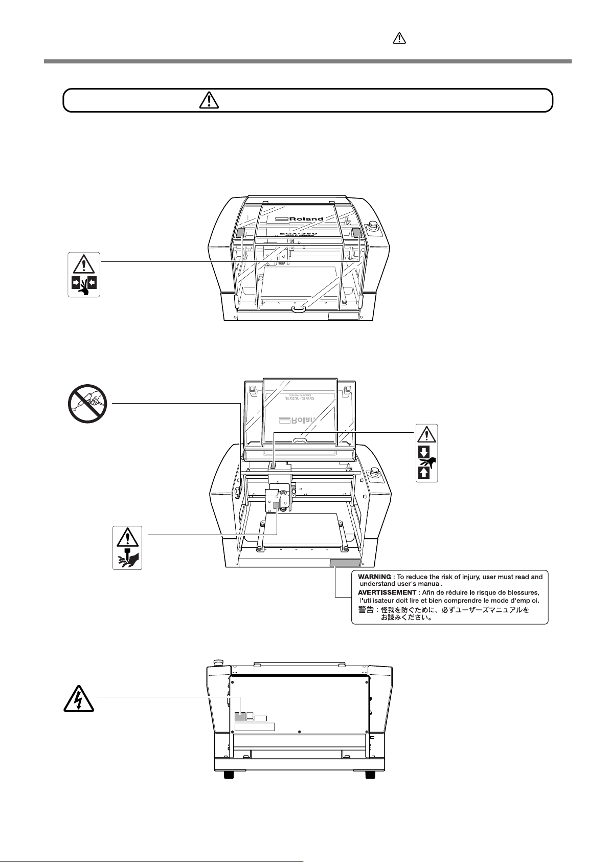
Warning Labels
Warning labels are affixed to make areas of danger immediately clear. The meanings of these
labels are as follo ws. Be sure to heed their warnings.
Also, never r emove the labels or allow them to become obscured.
Top
Caution: Pinching Hazard
Be careful not to allow the fingers to
become pinched when loading media
or closing covers.
Never use a pneumatic blower.
This machine is not compatible with
a pneumatic blower. Cutting waste
may get inside the machine and
cause fire or electrical shock.
Caution: Sharp Tool
Inadvertent contact may
cause injury.
Front/Inside
Caution: Pinching Hazard
Contact during operation may
cause the hand or fingers to
become pinched, resulting in
injury.
Rear
Caution: High Voltage
Cover removal may pose hazard of
shock or electrocution due to high
voltage.
10
Page 13
Pour utiliser en toute sécurité
La manipulation ou l'utilisation inadéquates de cet appareil peuvent causer des blessures ou
des dommages matériels. Les précautions à pr endre pour prévenir les blessur es ou les dommages
sont décrites ci-dessous.
Avis sur les avertissements
Utilisé pour avertir l'utilisateur d'un risque de décès ou de blessure grave en
ATTENTION
PRUDENCE
À propos des symboles
cas de mauvaise utilisation de l'appareil.
Utilisé pour avertir l'utilisateur d'un risque de blessure ou de dommage matériel
en cas de mauvaise utilisation de l'appareil.
* Par dommage matériel, il est entendu dommage ou tout autre effet
indésirable sur la maison, tous les meubles et même les animaux
domestiques.
Le symbole attire l'attention de l'utilisateur sur les instructions importantes ou les
avertissements. Le sens précis du symbole est déterminé par le dessin à l'intérieur du triangle.
Le symbole à gauche signifie "danger d'électrocution."
Le symbole avertit l'utilisateur de ce qu'il ne doit pas faire, ce qui est interdit. La chose
spécifique à ne pas faire est indiquée par le dessin à l'intérieur du cercle. Le symbole à gauche
signifie que l'appareil ne doit jamais être démonté.
Le symbole prévient l'utilisateur sur ce qu'il doit faire. La chose spécifique à faire est indiquée
par le dessin à l'intérieur du cercle. Le symbole à gauche signifie que le fil électrique doit être
débranché de la prise.
11
Page 14
Pour utiliser en toute sécurité
L’utilisation incorrecte peut causer des blessures
ATTENTION
S’assurer de suivre les procédures
d’utilisation décrites dans la documentation. Ne jamais permettre à quiconque ne
connaît pas le fonctionnement ou la
manutention de l’appareil de le toucher.
L’utilisation ou la manutention incorrectes
peuvent causer un accident.
Garder les enfants loin de l’appareil.
L’appareil comporte des zones et des
composants qui présentent un danger pour les
enfants et qui pourraient causer des blessures,
la cécité, la suffocation ou d’autres accidents
graves.
Ne jamais faire fonctionner l’appareil
après avoir consommé de l’alcool ou des
médicaments, ou dans un état de fatigue.
L ’utilisation de l’appareil exige un jugement sans
faille. L’utilisation avec les facultés affaiblies
pourrait entraîner un accident.
Utiliser l’appareil dans un endroit propre
et bien éclairé.
T ra vailler dans un endroit sombr e ou encombré
peut causer un accident; l’utilisateur risque, par
exemple, de trébucher malencontreusement et
d’être coincé par une partie de l’appareil.
ATTENTION
Débrancher le câble d’alimentation avant
de procéder au nettoy age ou à l’entr etien
de l’appareil, et avant d’y fixer ou d’en
retirer des accessoires en option.
Tenter ces opérations pendant que l’appareil est
branché à une source d’alimentation peut causer
des blessures ou un choc électrique.
Ne jamais tenter de démonter , de réparer
ou de modifier l’appareil.
Le non-respect de cette consigne risque de
provoquer un incendie, un choc électrique ou
des blessures. Confier les réparations à un
technicien ayant la formation requise.
PRUDENCE
Ne jamais grimper ni s’appuyer sur la
machine.
La machine n’est pas conçue pour supporter le
poids d’une personne. Grimper ou s’appuyer sur
la machine peut déplacer des éléments et causer
un faux pas ou une chute, ce qui causerait des
blessures.
Ne jamais utiliser l’appareil à des fins
autres que celles pour lesquelles il est
conçu. Ne jamais l’utiliser de manière abusive ou d’une manière qui dépasse sa
capacité.
Le non-respect de cette consigne peut causer
des blessures ou un incendie.
Ne jamais utiliser un outil de coupe
émoussé. Procéder fréquemment aux
travaux d’entretien pour gar der l’appareil
en bon état de fonctionnement.
L’usage abusif peut causer un incendie ou des
blessures.
Utiliser uniquement des accessoires
d’origine (accessoires en option, articles
consommables, câble d’alimentation et
autres articles semblables), compatibles
avec l’appar eil.
Les articles incompatibles risquent de causer des
accidents.
12
Page 15
Pour utiliser en toute sécurité
Le poids de cet appareil est de 34 kg (75 lb.)
Les débris de coupe peuvent s ’enflammer ou présenter un
risque pour la santé.
PRUDENCE
Le déchargement et la mise en place
doivent être faits par au moins ****
personnes.
Les tâches qui exigent un effort trop grand si
elles sont exécutées par un petit nombre de
personnes peuvent être cause de blessures. La
chute d’articles très lourds peut aussi causer des
blessures.
ATTENTION
Ne jamais tenter de couper du magnésium
ni aucun autre matériau inflammable.
Un incendie pourrait se produire pendant la
coupe.
Ne pas approcher une flamme nue de
l’espace de travail.
Les rognures de coupe peuv ent s’enflammer . Les
matériaux pulvérisés sont extrêmement
inflammables et même le métal peut s’enflammer .
PRUDENCE
Installer l’appareil à un endroit stable et
plat.
Installer l’appareil à un endroit ina pproprié peut
provoquer un accident grave comme le
renversement ou la chute.
PRUDENCE
Porter des lunettes de protection et un
masque. Rincer toutes les rognures de
coupe qui pourraient rester collées aux
mains.
Avaler ou respirer accidentellement des
rognures de coupe peut êtr e dangereux pour la
santé.
Si un aspirateur est utilisé pour ramasser
les rognur es de coupe, faire preuv e de prudence pour empêcher que la poussière
s’enflamme ou explose.
Ramasser des rognures fines à l’aide d’un
aspirateur ordinaire peut créer un risque
d’incendie ou d’explosion. Vérifier auprès du
fabricant de l’aspirateur. Dans les cas où il est
impossible de déterminer si un aspirateur peut
être utilisé sans danger, se servir d’une brosse
ou d’un article semblable plutôt que d’un
aspirateur.
13
Page 16
Pour utiliser en toute sécurité
Certains éléments peuvent présenter un risque de pincement,
d’emmêlement, de brûlure ou d’autres dangers.
ATTENTION
Ne jamais faire fonctionner l’appareil si on
porte une cravate, un collier ou des
vêtements amples. Bien attacher les
cheveux longs.
Ces vêtements ou ces objets peuvent être
coincés dans l’appareil, ce qui causerait des
blessures.
Fixer solidement l’outil de coupe et la
pièce à travailler. Une fois qu’ils sont fixés
solidement, s’assurer qu’aucun outil ni
aucun autre objet n’a été laissé en place.
Si tel était le cas, ces objets pourraient être
projetés avec force hors de l’appareil et causer
des blessures.
ATTENTION
Faire preuve de prudence pour éviter
l’écrasement ou le coincement.
La main ou les doigts peuvent être écrasés ou
coincés s’ils entrent en contact avec certaines
surfaces par inadvertance. Faire preuve de prudence pendant l’utilisation de l’appareil.
Attention : outil de coupe.
L ’outil de coupe est acéré. Faire preuve de prudence pour éviter les blessures.
Attention : températures élevées.
L’outil de coupe et le moteur chauffent. Faire
preuve de prudence pour éviter un incendie ou
des brûlures.
14
Page 17
Pour utiliser en toute sécurité
Risque de décharge ou de choc électrique, d’électrocution ou d’incendie
ATTENTION
Brancher à une prise électrique conforme
aux caractéristiques de cet appareil (tension, fréquence et courant).
Une tension incorrecte ou un courant insuffisant
peuvent causer un incendie ou un choc
électrique.
Caractéristiques
Never use out of doors or in any location
where exposure to water or high humidity may occur . Never touch with wet hands.
Doing so may result in fire or electrical shock.
Ne jamais insérer d’objet étranger dans
l’appareil. Ne jamais e xposer l’appareil aux
déversements de liquides.
L’insertion d’objets comme des pièces de
monnaie ou des allumettes, ou le déversement
de liquides dans les orifices de ventilation
peuvent causer un incendie ou un choc
électrique. Si un objet ou du liquide s’infiltre dans
l’appareil, débrancher immédiatement le câble
d’alimentation et communiquer avec le
représentant Roland DG autorisé.
Ne jamais placer d’objet inflammable à
proximité de l’a ppareil. Ne jamais utiliser
de produit inflammable en aérosol à
proximité de l’a ppareil. Ne jamais utiliser
l’appareil dans un endroit où des gaz
peuvent s’accumuler.
Une combustion ou une explosion pourraient
se produire.
Mise à la terre.
La mise à la terre peut prévenir un incendie ou
un choc électrique dus à une fuite de courant
en cas de défaillance.
ATTENTION
Manipuler le câble d’alimentation, la fiche
et la prise électrique correctement et a vec
soin.
Ne jamais utiliser un article endommagé, car cela
pourrait causer un incendie ou un choc
électrique.
Si une rallonge ou une bande
d’alimentation électrique sont utilisées,
s’assurer qu’elles correspondent aux
caractéristiques de l’appareil (tension,
fréquence et courant).
L ’utilisation de plusieurs charges électriques sur
une prise unique ou une longue rallonge peut
causer un incendie.
Si l’appareil doit rester inutilisé pendant
une longue période, débrancher le câble
d’alimentation.
Cela peut prévenir les accidents en cas de fuite
de courant ou de démarrage accidentel.
Placer l’appareil de façon à ce que la fiche
soit facile d’accès en tout temps.
Ainsi, l’appareil pourra être débranché
rapidement en cas d’urgence. Installer l’a ppareil
près d’une prise électrique. En outre, prévoir
suffisamment d’espace pour que la prise
électrique soit facile d’accès.
Ne jamais utiliser d’huile de coupe.
Cet appareil n’est pas conçu pour traiter l’huile
de coupe. L’huile peut s’infiltrer à l’intérieur et
causer un incendie ou un choc électrique.
Ne jamais utiliser d’air sous pression.
Cet appareil n’est pas conçu pour être nettoyé
à l’aide d’un appareil soufflant. Des rognures de
coupe peuvent s’infiltrer à l’intérieur et causer
un incendie ou un choc électrique.
S’il se produit des étincelles, de la fumée,
une odeur de brûlé, un bruit inhabituel ou
un fonctionnement anormal, débrancher
immédiatement le câble d’alimentation.
Ne jamais utiliser si un composant est
endommagé.
Continuer à utiliser l’appareil peut causer un
incendie, un choc électrique ou des blessures.
Communiquer avec le r eprésentant Roland DG
Autorisé.
15
Page 18
Pour utiliser en toute sécurité
Remarques importantes à propos du câble d'alimentation, de la fiche et de la prise électrique
Ne jamais déposer aucun objet sur le câble, sur la fiche
ou sur la prise car cela risque de les endommager.
Ne jamais plier ni tordre le câble avec une
force excessive.
Ne jamais laisser l'eau toucher le câble, la
fiche ou la prise.
Ne jamais chauffer le câble, la fiche ou la
prise.
16
Ne jamais tirer sur le câble ou la fiche avec
une force excessive.
Ne jamais plier ni enrouler le câble.
La poussière peut causer un incendie.
Page 19
Pour utiliser en toute sécurité
Vignettes d'avertissement
Des vignettes d'avertissement sont apposées pour qu'il soit facile de repérer les zones
dangereuses. La signification des vignettes est donnée ci-dessous. Respecter les a vertissements.
Ne jamais retirer les vignettes et ne pas les laisser s'encrasser.
Haut
Attention : Risque de pincement
Faire attention de ne pas coincer les
doigts pendant le chargement du
support ou lors de la fermeture du
couvercle.
Ne jamais utiliser d’air sous
pression.
Cet appareil n’est pas conçu pour
être nettoyé à l’aide d’un appareil
soufflant. Des rognures de coupe
peuvent s’infiltrer à l’intérieur et
causer un incendie ou un choc
électrique.
Attention : outil coupant
Un contact imprudent
risque d’entraîner une
blessure.
Avant/intérieur
Attention : risque de
pincement
Un contact pendant le
fonctionnement peut
coincer la main ou les
doigts ce qui risque de
causer des blessures.
Arrière
Attention : voltage élevé
Il peut être dangereux de retirer le
couvercle puisqu’il y aurait des risques
de chocs électriques ou
d’électrocution à cause du voltage
élevé.
17
Page 20

Important Notes on Handling and Use
This machine is a precision device. To ensure the full performance of this machine, be sure to observe the
following important points. Failure to observe these may not only result in loss of perf ormance, but may also
cause malfunction or breakdown.
This machine is a precision device.
➢Handle carefully, and never subject the machine to impact or excessive force.
➢Use within the range of specifications.
➢Diligently keep clean of cutting waste.
➢Never needlessly touch anywhere inside the machine except for locations specified in this manual.
Install in a suitable location.
➢Install in a location that meets the specified conditions for temperature, relative humidity, and the like.
➢Install in a quiet, stable location offering good operating conditions.
➢Never install in out of doors.
This machine becomes hot.
➢Never cover the ventilation holes with cloth, tape, or anything else.
➢Install in a well-ventilated location.
About Cutters
➢Use a cutter that is suitable for the workpiece and the cutting method.
➢The tip of the cutter is breakable. Handle with care, being careful not to drop it.
18
Page 21

About the Documentation for This Machine
Documentation Included with the Machine
The following documentation is included with the machine.
User's Manual (this manual)
This describes important notes for ensuring safe use, and explains how to install and operate the machine. Be
sure to read it first.
It does not describe how to operate your computer or how to use the programs.
Roland Software Package Software Guide
This explains how to install included program and other software and details.
Be sure to read this, when connecting the machine to a computer.
Roland EngraveStudio Software Guide
This explains how to install included program and other software and details.
Dr. Engrave User's Manual (electronic-format manual)
This manual explains how to use the included engraving program. It describes procedures ranging from how to
design a nameplate or the like to engraving operations. Read it if you're using this program.
The manual is in electronic format, and no printed document is included. Y ou can find it on the included Roland
Software Package CD-ROM.
3D Engrave User's Manual (electronic-format manual)
This manual explains how to use the included program for three-dimensional engraving and for creating reliefs.
It describes procedures ranging from how to design reliefs and the like to cutting operations. Read it if you're
using this program.
The manual is in electronic format, and no printed document is included. Y ou can find it on the included Roland
Software Package CD-ROM.
EngraveStudio User's Manual (electronic-format manual)
This is the documentation for using the included three-dimensional (relief) engraving program. It describes the
steps from designing text and shapes to engrave on wooden signs and the like through to the engraving operations. Read it if you're using this program.
The manual is in electronic format, and no printed document is included. Y ou can find it on the included Roland
EngraveStudio CD-ROM.
Virtual MODELA User's Manual (electronic-format manual)
This is the documentation for a program that creates previews by simulating cutting using 3D Engrave. It describes all the steps from receiving data created using 3D Engrave to simulation of cutting operations. Read it if
you're using this program.
The manual is in electronic format, and no printed document is included. Y ou can find it on the included Roland
Software Package CD-ROM.
19
Page 22

20
Page 23

Chapter 1
Getting Started
21
Page 24

1-1 Machine Highlights
Featur es
➢ Engraving and relief-cutting on a single machine
This machine achieves expressive, high-quality engraving of a wide range of types, from flat engraving to threedimensional reliefs.
➢ Outstanding basic performance
The spacious operating area measuring 40 millimeters high b y 305 millimeters wide b y 230 millimeters deep and the
high-speed spindle that turns at up to 20,000 rpm make for rapid engraving. W orkpieces up to 40 millimeters thick can
be accommodated.
➢ Accommodates a wide variety of engraving materials
The machine can engr ave a wide r ange of workpiece materials, from plastics, acrylics, and other resin-based materials
to light metals such as aluminum and brass.
➢ Designed for ease of use
You control machine operation using a handy panel that is separate from the machine. This lets you control the
machine from a location affording a clear view of the workpiece and tool. You can also make the settings for the
machine simply and easily while viewing the display screen on the handy panel.
➢ Automatic Z control feature
The machine offers an automatic Z control feature that makes possible engr aving at a uniform depth, even on workpieces
with wavy surfaces.
(Trackable undulation height: gentle undulations of about 1 millimeter)
➢ High levels of safety
A front cover and an emergency-stop button are standard features of the machine.
22
Chapter 1 Getting Started
Page 25
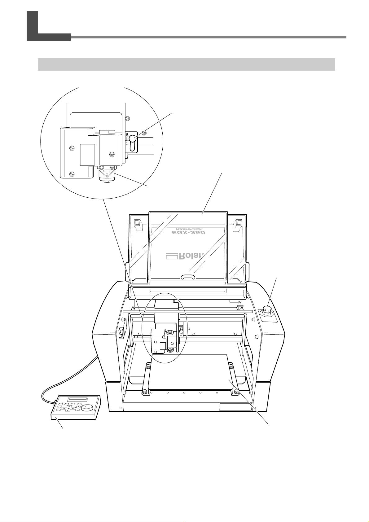
1-2 P art Names and Functions
Fr ont and Interior
Spindle head *
Lock lever
This locks or unlocks the spindle head.
☞ P. 82, "The Position of the Lock Lever"
Front cover
To ensure safety, opening this during engraving
Spindle unit
or spindle rotation causes an emergency stop to
occur.
☞ P. 39, "Emergency Stop Due to Opening or Closing the Front Cover"
Handy panel
This is used to perform cutter movement and other
machine operations, and to make various settings.
☞ P. 42, "Using the Handy Panel."
Emergency Stop button
Pressing this stops
operation of the
machine.
☞ P. 38, "Types of Emergency Stops to Ensure
Safety"
Workpiece table
The workpiece to be engraved is mounted on this.
* In this manual, the mechanisms around the spindle unit, including the spindle motor, are called the “spindle head.”
Also, the rotary-axis area inside the spindle unit is called the “spindle.”
Chapter 1 Getting Started
23
Page 26
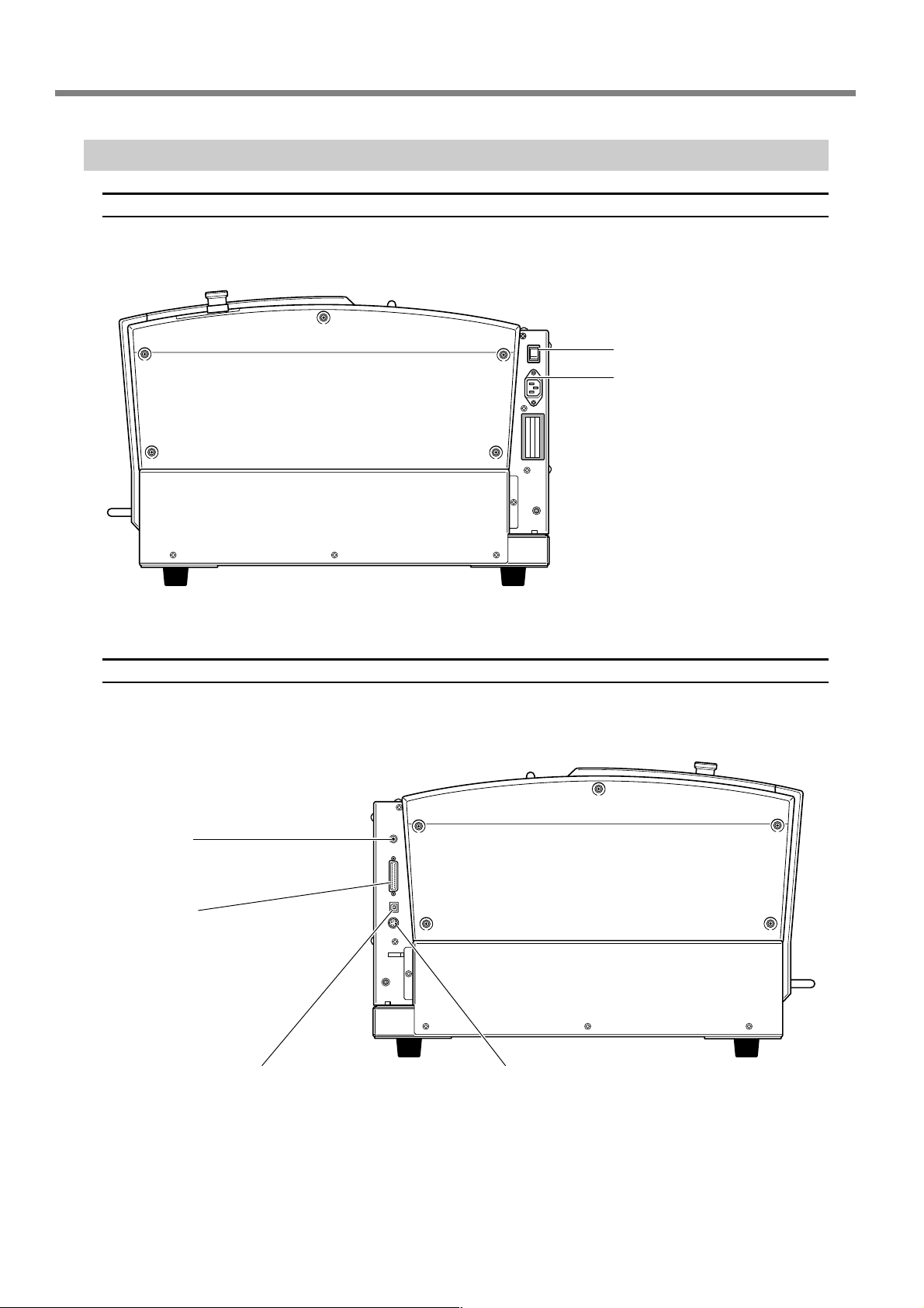
1-2 Part Names and Functions
Side
Right side
Power switch
Power-cord connector
Left side
Expansion port
This is a connector for external equipment.
☞ P. 111, “Expansion Connector”
Serial connector
This is for connecting a serial (RS-232Ccompliant) cable.
☞ P . 32, “Connecting a Computer Via a Communication Cable”
USB connector
This is for connecting a USB cable.
☞ P. 32, “Connecting a Computer Via
a Communication Cable”
Handy-panel connector
This is for connecting the handy panel.
☞ P. 30, “Connecting the Handy Panel”
24
Chapter 1 Getting Started
Page 27

Chapter 2
Installation and Setup
25
Page 28
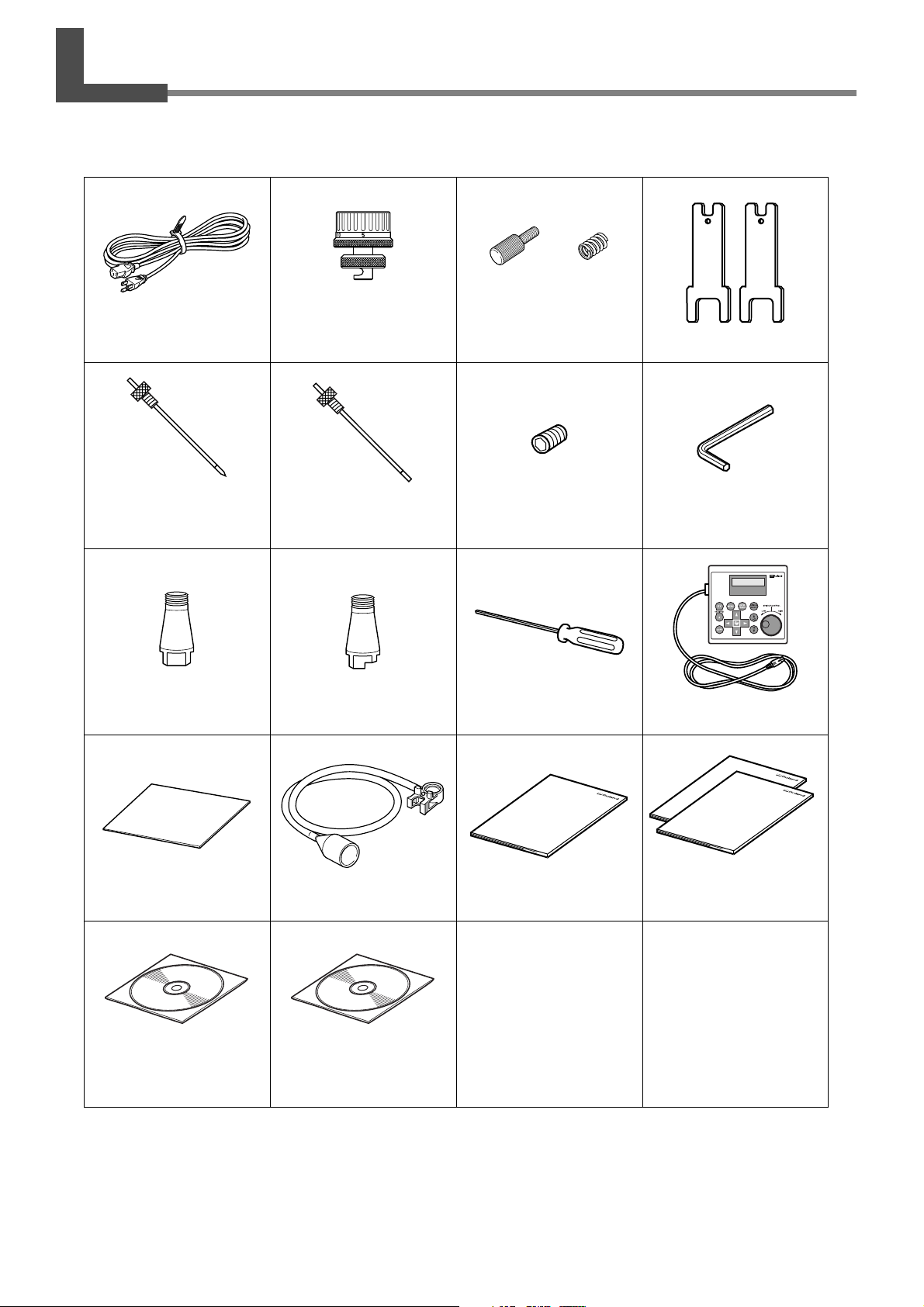
2-1 Checking the Included Items
The following items are included with the machine. Make sure they are all present and accounted for.
Power cord
Character cutter
(diameter 3.175 mm,
with cutter holder)
Collet
(diameter 3.175 mm)
Depth regulator nose
(nose unit)
Flat cutter
(diameter 3.175 mm,
with cutter holder)
Collet
(diameter 4.36 mm)*1,*2
Retaining
screw
Noes-unit retainer
Spare tool retaining screw
Hexagonal screwdriver
Spring
Wrench
Hexagonal wrench
Handy panel
26
Software guide
(Roland Software Package)
Adhesive sheet Vacuum-adapter set User’s Manual
Roland Software Package
CD-ROM
*1: This is for diameter-4.36 mm character or flat cutters. It cannot be used with diamond scrapers or end mills.
*2: Never use a diameter-4.36 mm cutter at a spindle speed of 15,000 rpm or higher. T here is danger of damage to the
spindle unit due to vibration.
Roland Engrave Studio
CD-ROM
(Roland Engrave Studio)
Chapter 2 Installation and Setup
Page 29

2-2 Installation
About Emplacement and Installation
WARNING
The weight of the machine alone is 34 kg (75 lb.). Perform unloading and emplacement with care.
Unloading and emplacement are operations that must be performed by 2 persons
or more.
Tasks that require undue effort when performed by a small number of persons ma y result
in physical injury. Also, if dropped, such items may cause injury.
Installation Environment
Install in a quiet, stable location offering good operating conditions. An unsuitable location can cause accident, fire,
faulty operation, or breakdown.
WARNING
WARNING
WARNING
WARNING
Install in a location that is level and stable.
Installation in an unsuitable location may cause an accident, including a fall or tipover.
Never install in a location exposed to open flame.
Cutting waste may ignite. Powdered material is extremely flammable, and even metal
material may catch fire.
Never install close to any flammable object or in a gas-filled location.
Combustion or explosion may be a danger.
Never install out of doors or in any location where exposure to water or high
humidity may occur.
Doing so may result in fire or electrical shock.
WARNING
➢ Never install in a location subject to wide fluctuations in temperature or humidity.
➢ Never install in a location subject to shaking or vibration.
➢ Never install in a locations where the floor is tilted, not level, or unstable.
➢ Never install in a dusty or dirty location, or out of doors.
➢ Never install in a location exposed to direct sunlight or near air-conditioning or heating equipment.
➢ Never install in a location exposed to considerable electrical or magnetic noise, or other forms of electromagnetic
energy.
Position so that the power plug is within immediate reach at all times.
This is to enable quick disconnection of the power plug in the event of an emergency.
Install the machine next to an electrical outlet. Also, provide enough empty space to allo w
immediate access to the electrical outlet.
Chapter 2 Installation and Setup
27
Page 30
2-2 Installation
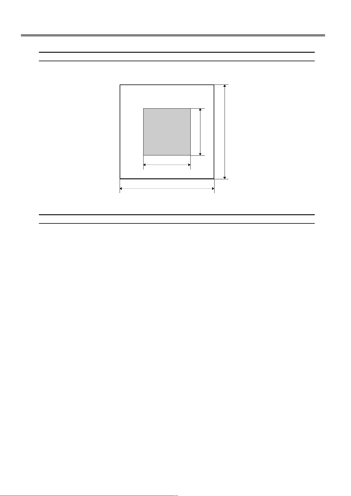
Installation Space
Ensure that at least the following amount of space is available.
Work space
Installation space
1.0 m (3.3 ft.)
1.0 m (3.3 ft.)
2.0 m (6.6 ft.)
2.0 m (6.6 ft.)
Height of Installation
The height of installation should be 0.6 m (23.7 in.) or higher above the work floor.
This machine is desktop type. Please decide the height of installation so that y ou can easily reac h the emergenc y stop
button when operating this machine.
28
Chapter 2 Installation and Setup
Page 31

2-2 Installation
Unpacking
Retaining materials are attached to protect the machine from vibration during shipment. Remov e these after emplacement.
➢ Remove all Retaining materials. Any that remain may cause faulty operation or breakdown when the power is
switched on.
➢ The Retaining materials are required when moving the mac hine to a different location. Store them carefully so that
they do not get misplaced.
WARNING
Carry out these operations before you connect the power cord.
Inadvertent powerup may result in pinched hands or other injury.
Procedure
Make sure the power cord is not connected.
➊
➋
Hexagonal wrench
➌
Remove retainer A.
Retainer A
Slowly move the spindle head in the direction of the arrow.
Take care not to subject it to strong impact.
➍
Spindle head
Retainer B Retainer C
Hexagonal wrench
Remove retainers B and C.
Chapter 2 Installation and Setup
29
Page 32

2-3 Cable Connections
Connecting the Handy Panel
Make sure the power to the machine is switched off before attempting to connect or disconnect cables.
Connecting the handy panel while the power is on makes the handy panel unusable.
Left side
Insert fully and
securely.
Handy panel
Cable clamp
30
Chapter 2 Installation and Setup
Page 33

Connecting the Power Cord
2-3 Cable Connections
WARNING
WARNING
WARNING
WARNING
WARNING
This machine requires a single-phase commercial power outlet, which rated at 1.3 A or higher ( for 100 to 120 V) or
0.6 A or higher (for 220 to 240 V).
Right side
Connect to an electrical outlet that complies with this machine's ratings (for voltage and frequency).
Incorrect voltage or insufficient current may cause fire or electrical shock.
Handle the power cord, plug, and electrical outlet correctly and with care. Never
use any article that is damaged.
Using a damaged article may result in fire or electrical shock.
When using an extension cord or power strip, use one that adequately satisfies the
machine's ratings (for voltage, frequency, and current).
Use of multiple electrical loads on a single electrical outlet or of a lengthy extension cor d
may cause fire.
Connect to ground.
This can prevent fire or electrical shock due to current leakage in the event of malfunction.
Connect to an electrical outlet. Never connect directly to a power distribution
panel or other such fixed wiring equipment.
Doing so increases the hazard of fire or electrical shock.
Electrical outlet
Power cable
Chapter 2 Installation and Setup
31
Page 34

2-3 Cable Connections
Connecting a Computer Via a Communication Cable
USB cable
At this time, keep the cable unconnected until you carry out this operation.
Follow the instructions in the separate Roland Software Package Software Guide to make the connection.
☞ P. 19, "About the Documentation for This Machine"
➢Never connect two or more machines to one computer.
➢Use a shielded USB cable having a length of 3 m (10 ft.) or less.
➢Never use a USB hub.
USB port
USB cable
Computer
At this time, keep the cable unconnected until you carry out
this operation.
Left side
Serial cable
Using a serial cable requires making the settings for the communication parameters with the computer.
For the serial cable, use a separately available XY-RS-34 from Roland DG Corp.
☞ P. 85, "Submenus," p. 110, "Serial Connector"
Secure in place with the screws.
Left side
32
RS-232C connector
Computer
Chapter 2 Installation and Setup
Serial cable
Page 35

2-4 Selecting the Language
Selecting the Language Used for Text on the Display Screen
Procedure
➊
➋
Close the front cover.
Hold down and turn on the
power switch.
ON
➌
➀➁
Use or to select the
➀
language.
Press to confirm.
➁
Chapter 2 Installation and Setup
33
Page 36

2-4 Selecting the Language
➍
Switch off the power switch.
OFF
34
Chapter 2 Installation and Setup
Page 37

2-5 Before Starting Operations
Spindle Run-in (Warm-up)
In any of the following cases, perform run-in (warm-up) operation for the spindle. Failure to do so may result in
unstable spindle rotation.
➢ When using for the first time after purchase
➢ After moving the machine and reinstalling it at a different location
➢ After replacing the spindle unit
➢ When using in a low-temperature environment
How to Perform Run-in (Warm-up) Operation
Carry out the following steps 1 through 4.
☞ P. 47, “Starting and Stopping Spindle Rotation”
Step 1
Speed : 5,000 rpm
Rotation time : 15 minutes
Step 2
Speed : 10,000 rpm
Rotation time : 10 minutes
Step 3
Speed : 15,000 rpm
Rotation time : 10 minutes
Step 4
Speed : 20,000 rpm
Rotation time : 15 minutes
Chapter 2 Installation and Setup
35
Page 38

36
Page 39

Chapter 3
Basic Oper ation
37
Page 40

3-1 Types of Emergency Stops to Ensur e Saf ety
How to Perform an Emergency Stop
Press the Emergency Stop button.
Operation stops immediately.
Emergency
Stop button
To Cancel an Emergency Stop
Procedure
➊
➋
Switch off the power switch.
OFF
Turn the button in the direction of the
arrows.
38
Emergency
Stop button
Chapter 3 Basic Operation
Page 41

3-1 Types of Emergency Stops to Ensure Safety
Emergency Stop Due to Opening or Closing the F ront Cover
T o ensure safety, opening the front cover during engraving or spindle rotation causes an emergenc y stop to occur, and
the message shown below appears on the display screen. Oper ation cannot be resumed by closing the front co v er. To
resume, switch off the power, then start up again.
☞ P. 40, “Starting and Quitting”
Front cover
Chapter 3 Basic Operation
39
Page 42

3-2 Starting and Quitting
How to Start the Machine
Follow the procedure below to start the machine. When startup is complete, the machine is ready for use.
Procedure
➊
➋
Close the front cover.
Switch on the power switch.
A message like the one shown in the figure
appears on the handy panel’s display screen.
ON
40
Note: “XXX” indicates the version number of the machine’s firmware.
Chapter 3 Basic Operation
Page 43

3-2 Starting and Quitting
➌
Main screen
When the screen shown in the figure at left appears after
approximately three seconds, press
The spindle head moves to a location on the inner-left side of the
machine. This operation is called “initialization.”
The default for the language used for on-screen display is English.
To change the display language to Japanese, refer to the page indicated below and change the language setting.
☞ P. 33, "Selecting the Language Used for Text on the Display Screen"
When initialization ends, the screen changes to a display like that
shown at left (the mainscreen). This completes initialization.
.
Shutdown
Dark
OFF
Make sure the machine is not in operation, then turn off the power switch.
The display screen on the handy panel goes
dark.
Chapter 3 Basic Operation
41
Page 44

3-3 Using the Handy P anel
Display screen
Menus, messages, and the like are displayed
here.
Dial
This adjusts the spindle’s speed of rotation.
Indication used in this manual:
☞ P. 48, "Adjusting the Spindle Speed"
MENU Button
Pressing this changes the menu screen. Also,
pressing this when at the origin-setting menu
returns the screen to the coordinate display
view (the main menu).
Indication used in this manual:
Enter/Pause button
This executes a selected on-screen item or
confirms a selected item or value.
Confirming an item or value displays the setting enclosed between angled brackets
("<>"). Pressing this during engraving pauses
operation and displays the Pause menu.
Indication used in this manual:
Spindle button
Holding this down for one second or longer
while the spindle is stopped makes spindle
rotation start. Pressing this during spindle
rotation makes the rotation stop. (When rotation is stopped, holding the button down
for one second or longer is not necessary.)
Indication used in this manual:
☞ P. 47, "Star ting and Stopping Spindle Rotation"
X/Y-axis Origin Set button
This sets the reference point for the cutting
position.
Indication used in this manual:
☞ P. 75, "Setting the XY Origin Point (Home Position)"
Z-axis Origin Set button
This sets the reference point for the cutting
position.
Indication used in this manual:
☞ P. 62, "Cutter Installation Method 2," p. 71, "Cutter Installation
Method 4"
Copy button
This calls up the menu for the copy feature.
Indication used in this manual:
☞ P. 78, "Executing Repeated Cutting"
Movement buttons
These move the cutter forw ard and backward, and
to the left and right. You also use them to select
items and change settings at menu screens.
Indication used in this manual:
☞ P. 44, "Manual Movement"
Z-axis Movement buttons
These move the cutter up and down.
Indication used in this manual:
☞ P. 44, "Manual Movement"
Feed button
Pressing a Movement or Z-axis Movement
button while holding down this button
makes the tool move rapidly.
Indication used in this manual:
☞ P. 44, "Manual Movement"
42
Chapter 3 Basic Operation
Page 45

3-4 Mo ving the Cutter
Terms Indicating the Cutter Position
This manual uses the following terms to indicate the position of the cutter.
➢ Coordinates
Numerical values indicating the location of the cutter
➢ Origin
The point of origin for the coordinates
➢ X-axis coordinate
The distance along the X axis from the origin point
➢ Y -axis coordinate
The distance along the Y axis from the origin point
➢ Z-axis coordinate
The distance along the Z axis from the origin point
Viewing the Cutter Position
The cutter position is displayed on the handy panel’s main screen.
The figure below shows the main screen w hen the cutter has mo ved from the origin point b y 50 millimeters along the
X axis, 30 millimeters along the Y axis, and 20 millimeters along the Z axis.
In the indication of coordinates used on this machine, a unit of “1” corresponds to 0.01 millimeter.
Main screen
Origin
20 mm
This position is displayed as
“X = 5000, Y = 3000, Z = 2000.”
50 mm
30 mm
Chapter 3 Basic Operation
43
Page 46

3-4 Moving the Cutter
Manual Movement
When the screen on the handy panel displays any one of the messages shown in the figure below, you can move the
cutter manually using the movement buttons.
☞ P. 84, "Menu List"
Handy panel
Movement along all axes
(X, Y, and Z)
Movement along only the X
and Y axes
+
Y
+
-
X
Movement along only the Z
axis
(“XXX” is “DOWN,” “SURFACE,” or “UP.”)
Movement buttons
➢ Each single press of , , , , or performs movement by 0.01 millimeter.
➢ Holding down , , , , or performs slow continuous movement.
➢ Holding down while pressing and holding , , , , or performs r apid
continuous movement.
+
X
-
Y
Z
-
Z
+
Z
-
Z
-
X
+
Y
+
X
-
Y
44
Important!
This operation is not possible in the following cases.
➢ When engraving is in progress
➢ When operation is paused
Chapter 3 Basic Operation
Page 47

Moving to a Specific Position Automatically
Procedure
Close the front cover.
➊
3-4 Moving the Cutter
➋
➌
At the main screen, press twice.
Press , , , or to select the movement destination.
➢ HOME
This is the location where the X- and Y-axis coordinates are both
“0” (the XY origin point). When movement b y this operation is per formed, to avoid contact with the workpiece, the mac hine first rises
to the highest point along the Z axis, and then performs movement.
☞ P. 75, “Setting the XY Origin Point (Home Position)”
➢ VIEW
This is the inner-left location on the workpiece table. You use it in
situations such as when mounting or removing a workpiece, or
when checking the state of the workpiece.
➢ Z0
This is the location where the Z-axis coordinate is “0.”
☞ P. 62, “Cutter Installation Method 2,” p. 71, “Cutter Installation Method 4,” and p.
92,“Origin-setting Menu”
➢ Z1
This is the location of the cutting-in depth when cutting the
workpiece.
☞ P. 92, “Origin-setting Menu”
➢ Z2
This is the height location along the Z axis when performing noload feed of the cutter during cutting.
☞ P. 92, “Origin-setting Menu”
Chapter 3 Basic Operation
45
Page 48

3-4 Moving the Cutter
➍
When the front cover is open, the screen shown in the figure below is displayed, and the cutter doesn’t move.
After three seconds the message disappears and the screen returns to the original menu.
Press .
The cutter moves to the selected location.
46
Chapter 3 Basic Operation
Page 49

3-5 Spindle Operation
Starting and Stopping Spindle Rotation
This manually starts and stops rotation of the spindle. You perform the operation using the handy panel.
☞ P. 35, "Spindle Run-in (Warm-up)"
Procedure
Close the front cover.
➊
➋
Spindle rotation speed
At the main screen, press and hold for one second
or longer.
A beep is heard, and the spindle starts to turn.
➌
This operation cannot be performed in the following situations.
➢ When the machine is performing some operation
➢ When the front cover is open (in which case the screen shown in the figure below is displayed)
☞ P. 103, “Responding to a Message”
Press .
The spindle stops turning, a beep is heard.
Chapter 3 Basic Operation
47
Page 50

3-5 Spindle Operation
Adjusting the Spindle Speed
Spindle speed
To adjust the speed of spindle rotation, turn
on the handy panel.
The setting for the spindle speed can be made only on
the machine. Any setting made on the computer is ignored.
FastSlow
48
Chapter 3 Basic Operation
Page 51

3-6 P ausing and Stopping Cutting
Pausing and Resuming Cutting
This pauses cutting through operation using the hand y panel. This enables you to move the cutter to the VIEW position
and check the status of the workpiece, then resume cutting at the location where you paused operation.
Procedure
➊
➋
➀➁
While cutting is in progress, press .
Movement of the cutter pauses. Rotation of the spindle does not
stop at this time.
The display screen shown at left appears.
Use to select “VIEW.”
➀
Press to confirm.
➁
Rotation of the spindle stops, and the cutter moves to the VIEW
position.
☞ P. 45, “Moving to a Specific Position Automatically”
➌
➀➁
Use or to select “CONT.”
➀
Press to confirm.
➁
The cutter returns to the location where paused, and cutting resumes.
Selecting “VIEW” or “CONT.” while the front cover is open makes
the message shown in the figure below appear . After three seconds
the message disappears and the screen returns to the original menu.
Close the front cover , then redo the selection of the operation item.
Chapter 3 Basic Operation
49
Page 52

3-6 Pausing and Stopping Cutting
Important!
Before opening the front cover while operation is paused, first make sure that rotation of the spindle is stopped. For
safety , opening the front co ver w hile the spindle is turning makes the mac hine perform an emergenc y stop. Be sure to
note that if this happens, it’s necessary to quit the operation and start over from the beginning.
☞ P. 39, “Emergency Stop Due to Opening or Closing the Front Cover”
Other operations possible while paused
➢ Starting or stopping spindle rotation
☞ P. 47, “Starting and Stopping Spindle Rotation”
➢ Changing the spindle speed
☞ P. 48, “Adjusting the Spindle Speed”
➢ Changing the feed rate of the cutter
☞ P. 77, “Adjusting the Cutter Feed Rate During Engraving (Override)”
Stopping Cutting
This stops cutting through operation using the handy panel. Unlike pausing operation, cutting cannot be resumed.
Procedure
➊
➋
➀➁
While cutting is in progress, press .
Movement of the cutter pauses. Rotation of the spindle does not
stop at this time.
The display screen shown at left appears.
Use to select “STOP.”
➀
Press to confirm.
➁
The cutter moves to the highest location on the Z axis, then stops.
If the spindle is rotating, its rotation stops here.
50
Chapter 3 Basic Operation
Page 53

Chapter 4
Engr aving
51
Page 54

4-1 Flo w of Engraving Operations
1.
Startup
Switch on the power switch to start the machine.
☞ P. 40, “How to Start the Machine”
ON
2.
Mounting the Workpiece
Mount the workpiece to engrave on the table.
☞ P. 54, “Mounting a Workpiece”
To next page
52
Chapter 4 Engraving
Page 55

4-1 Flow of Engraving Operations
Cutter Installation and Basic Engraving Settings
3.
Install the cutter to use for engraving. On this machine, you also set the Z-axis engraving origin
point at this time. The methods you use for installation and the settings differ depending on
whether you’re using the nose unit and on the cutter type. This manual describes the following
four variations. Use these as a reference to select the optimal cutter for the purpose and use the
appropriate methods for installing the cutter and making the settings.
➢ Character cutter or flat cutter (with the nose unit)
☞ P. 56, “Cutter Installation Method 1 (With Nose Unit)”
➢ Character cutter or flat cutter (no nose unit)
☞ P. 62, “Cutter Installation Method 2 (No Nose Unit)”
➢ Diamond scraper
☞ P. 67, “Cutter Installation Method 3”
➢ End mill
☞ P. 71, “Cutter Installation Method 4 (End mill)”
Setting the XY Origin Point
4.
Set the engraving origin point for the X and Y axes.
☞ P. 75, “Setting the XY Origin Point (Home Position)”
Performing Engravings
5.
When all the preparations are complete, send the engraving data from the computer and carry out
engraving.
☞ P. 76, “Performing Engraving”
Chapter 4 Engraving
53
Page 56

4-2 Mounting a Workpiece
WARNING
CAUTION
When Using an Adhesive Sheet
Never inadvertently touch the computer or handy panel while performing this
task.
Unintended operation of the machine may result in injury.
Caution: cutting tool.
The cutting tool is sharp. To avoid injury, exercise caution.
Affix the adhesive sheet to the
workpiece table, then place the
workpiece on the adhesive sheet and
press down on it from abo ve to secure
it in place.
Adhensive sheet
On this machine, you can also use optionally av ailable items to secure the workpiece in place: a center vise (ZV-23C)
or a vacuum table (ZV -23A). For detailed information about these optional items, contact your authorized Roland DG
Corp. dealer.
Workpiece
Workpiece table
54
Chapter 4 Engraving
Page 57

4-3 Selection of the Cutter (Usag e Examples)
This machine can use cutters of a wide variety of types that have a diameter of 3.175 millimeters or 4.36 millimeters.
Use an appropriate collet for the cutter’s diameter and type. For other cutters that can be used with the machine,
contact your authorized Roland DG Corp. dealer.
The table below shows samples of cutter usage, including use with or without a nose unit.
Important!
Use diameter-4.36 mm cutters at speeds of 15,000 rpm or lo wer. Use at higher speeds poses danger of damage to the
spindle unit due to vibration.
Cutter
Character cutter
Flat cutter
(*1)
Diamond scraper
(*3)
End mill (*4)
With nose unit
◆ Engraving acrylic and other plastic plates
(*2)
☞ P. 56, "Cutter Installation Method 1"
◆ Unsuitable
◆ Unsuitable
No nose unit
◆ Engraving plates of aluminum or brass
◆ Three-dimensional engra ving and creating re-
liefs using plastic materials
☞ P. 62, "Cutter Installation Method 2"
◆ Scribing plates of aluminum or brass
☞ P. 67, "Cutter Installation Method 3"
◆ Creating reliefs and performing 3D cutting
using plastic material
☞ P. 71, "Cutter Installation Method 4"
*1: Diameter-4.36 millimeter cutters are optionally available items.
*2: Use of the nose unit is not suitable for fill engraving at a width greater than the diameter of the nose-unit tip.
☞ P. 61, “Important Notes When Using the Nose Unit”
*3: This is an optionally available item. Also, the diameter-4.36 millimeter diamond scraper cannot be used with the
included solid collet. Provide a dedicated collet for diamond scrapers separately.
*4: This is an optionally available item. Provide a dedicated end-mill collet separately.
Chapter 4 Engraving
55
Page 58

4-4 Cutter Installation Method 1 (With Nose Unit)
Installing a Character Cutter (With Nose Unit)
WARNING
WARNING
CAUTION
Type of cutter used
Nose-unit usage
Suitable workpiece types
Automatic Z-axis control
Spindle rotation
Lock-lever position
This performs engraving using the nose unit. When the tip of the nose unit touches the surface of the workpiece, the
location is automatically detected as the Z origin point. T his makes it possible to perform engra ving at a uniform depth
on a workpiece of uneven surface height. This also eliminates the need to set the Z-axis origin point each time when
you’re engraving a number of different workpieces.
Never inadvertently touch the computer or handy panel while performing this
task.
Unintended operation of the machine may result in injury.
Securely fasten the cutting tool and in place. After securing in place, make sure no
wrenches or other articles have inadvertently been left behind.
Otherwise such articles may be thrown from the machine with force, posing a risk of
injury.
Caution: cutting tool.
The cutting tool is sharp. To avoid injury, exercise caution.
Character cutter or flat cutter
Used
Acrylic and other plastic-resin panels
Note: Aluminum, brass, and other easily scratched workpieces are not
suitable.
On
On
or
1.
Install the cutter holder, solid collet, and nose unit.
➊
Wrench
Cutter holder
Spindle unit
Install the cutter holder.
While holding the spindle unit immobile with
a wrench, tighten the cutter holder.
The cutter holder is reverse-threaded (that is,
you turn it counterclockwise to tighten it). Be
careful to turn it in the correct direction.
Hexagonal
screwdriver
Loose
Cutter holder
56
Chapter 4 Engraving
Page 59

4-4 Cutter Installation Method 1 (With Nose Unit)
➋
Wrench
Spindle unit
Wrench
➀
➁
Solid collet
Install the solid collet.
Loosely tighten the solid collet.
➀
Insert the solid collet into the spindle unit
from below, then, while holding the
spindle unit immobile with a wrench,
tighten loosely.
Use an appropriate solid collet for the
cutter’s diameter.
Fully tighten the solid collet.
➁
Using two wrenches, tighten the solid
collet fully. The appropriate tightening
torque is 3.2 N-m (32kgf-cm) .
➌
Wrench
Install the nose unit.
T ighten until no further movement is possible,
then loosen two turns.
☞ P. 61, “Important Notes When Using the Nose Unit”
Nose unit
Loose
Tighten
Chapter 4 Engraving
57
Page 60

4-4 Cutter Installation Method 1 (With Nose Unit)
2.
Set the lock lever.
Lock lever
Press down to lower
slightly.
Set the lock lever at the or position.
For detailed information about the setting
position for the lock lever, refer to the page
indicated below.
☞ P. 82, “The Position of the Lock Lever”
3.
Make the settings for spindle speed and Z-axis control.
➊
➋
➌
➍
Press several times to display the screen shown at left.
Use
Press
Press to select “ON.”
Press
Press .
Use
The machine automatically determines the Z-axis origin during cutting according to the height of the workpiece.
Press to confirm.
The message shown at left is displayed for three seconds, and then the original
screen returns.
Press .
Use
This makes the setting for the distance the cutter rises from the Z-axis origin
point during cutting (the cut-out amount). When making this setting, take into
account the shape of the workpiece and the time required for movement.
Press to confirm.
and to select [OTHERS].
.
to confirm.
to select “ON.”
and to select the value.
58
➎
Chapter 4 Engraving
Press several times to return to the main scr een.
The Z-axis coordinate display changes to “AUTO.”
Page 61

4-4 Cutter Installation Method 1 (With Nose Unit)
4.
Install the cutter and make the setting for the cutting-in depth.
➊
➋
Workpiece table
Cutter
Cutter holder
Use , , , and to
move the spindle head to the area abo ve
the workpiece, then press
to
lower the spindle head.
Descent stops automatically when the tip of
the nose unit touches the workpiece table.
☞ P. 44, “Manual Movement”
Insert the cutter into the cutter holder
and bring the tip of the cutter into contact with the workpiece table.
Workpiece table
If cutter insertion is difficult
If the cutter catches on the solid collet and is difficult
to insert, loosening the cutter holder makes insertion
easier. Note that inserting it with undue force may result in damage to the workpiece. After inserting the
cutter, tighten the cutter holder again.
Loosen the cutter holder.
When using a diameter -4.36 mm solid collet
Be careful to orient the cutter correctly.
Cutter
Solid collet
Tab
Tab
Chapter 4 Engraving
59
Page 62

4-4 Cutter Installation Method 1 (With Nose Unit)
➌
➍
Hexagonal
screwdriver
Retaining screw
➁
Cutter holder
Mounting screw
Nose unit
➀
Secure the cutter in place.
Tighten the mounting screw for the cutter
holder.
Make the setting for the cutting-in depth.
Tighten the nose unit to match the
➀
desired cutting-in depth.
The amount of extension of the cutter is
the cutting-in depth.
1 scale tick = 0.0254 mm (0.001 in.)
1 full turn = 0.635 mm (0.025 in.)
An amount of 4 to 8 scale ticks corresponds to 0.1 to 0.2 mm (0.004 to 0.008
in.).
Retaining
screw
Spring
This completes the installation of the cutter. Go on to page 75, “Setting the XY Origin Point (Home Position)."
Storage methods for diameter-3.175 mm cutters
When you want to perform repeated use while keeping the amount of extension of the cutter tip constant, then once
you’ve decided on the amount of extension, we recommend removing the cutter holder and cutter from the spindle unit
without separating them from one another. Storing the assembly without changing the position of the cutter holder eliminates the need to determine the amount of cutter extension each time with every use.
Note, however, that this method cannot be used with the included diameter-4.36 millimeter solid collet.
Secure the nose unit in place with
➁
the retaining screw.
60
Remove the entire cutter-holder assembly from the spindle unit.
Chapter 4 Engraving
Store without changing the position
of the cutter holder .
Page 63

4-4 Cutter Installation Method 1 (With Nose Unit)
Important Notes When Using the Nose Unit
Amount of Height Displacement That Can Be Tracked
When automatic Z control is set to “ON,” then as long as the tip of the nose unit is in contact with the surface of the
workpiece, the cutting-in depth can be kept uniform even if the height of the material changes. However, there is an
upper limit to the amount of height displacement that can be tracked. Before you do the actual engr aving, carry out an
engraving test to make sure the desired engraving can be accomplished.
(Trackable undulation height: gentle undulations of about 1 millimeter)
Limitations on Cutting
Care is needed when performing fill engraving (flat-dr ag cutting inside the contour lines of characters and shapes) o ver
a wide surface area. With fill engraving that is broader than the diameter of the nose unit, the nose unit may track the
surface that has already been cut and cut the surface further.
Nose unit
8 mm
Chapter 4 Engraving
61
Page 64

4-5 Cutter Installation Method 2 (No Nose Unit)
Installing a Character Cutter (With No Nose Unit)
WARNING
WARNING
CAUTION
Type of cutter used
Nose-unit usage
Suitable workpiece types
Automatic Z-axis control
Spindle rotation
Lock-lever position
This performs engra ving without using the nose unit. This method doesn’t scr ape the surface of the workpiece, so you
can also use it with materials such as aluminum or brass. Note, however, that the Z-axis origin point is fixed and
unchanging, so in order to obtain a uniform cutting-in depth, the thickness of the workpiece must also be uniform.
Never inadvertently touch the computer or handy panel while performing this
task.
Unintended operation of the machine may result in injury.
Securely fasten the cutting tool and in place. After securing in place, make sure no
wrenches or other articles have inadvertently been left behind.
Otherwise such articles may be thrown from the machine with force, posing a risk of
injury.
Caution: cutting tool.
The cutting tool is sharp. To avoid injury, exercise caution.
Character cutter or flat cutter
Not Used
Aluminum, brass
Off
On
1.
Install the cutter holder and solid collet.
➊
Wrench
Spindle unit
Install the cutter holder.
While holding the spindle unit immobile with
a wrench, tighten the cutter holder.
The cutter holder is reverse-threaded (that is,
you turn it counterclockwise to tighten it). Be
careful to turn it in the correct direction.
Hexagonal
screwdriver
Loose
Cutter holder
Cutter holder
62
Chapter 4 Engraving
Page 65

4-5 Cutter Installation Method 2 (No Nose Unit)
➋
Wrench
Spindle unit
Wrench
➀
➁
Solid collet
Install the solid collet.
Loosely tighten the solid collet.
➀
Insert the solid collet into the spindle unit
from below, then, while holding the
spindle unit immobile with a wrench,
tighten loosely.
Use an appropriate solid collet for the
cutter’s diameter.
Fully tighten the solid collet.
➁
Using two wrenches, tighten the solid
collet fully. The appropriate tightening
torque is 3.2 N-m (32kgf-cm) .
2.
Set the lock lever.
Wrench
Set the lock lever at the position.
The spindle head is secured in place.
☞ P. 82, "The Position of the Lock Lever"
Lock lever
Lift up.
Chapter 4 Engraving
63
Page 66

4-5 Cutter Installation Method 2 (No Nose Unit)
3.
Make the settings for spindle speed and Z-axis control.
➊
➋
➌
➍
4.
Install the cutter and set the Z-axis origin point.
Press several times to display the screen shown at left.
Use
Press
Use to select “ON.”
Press
Press .
Use
Press
The message shown at left is displayed for three seconds, and then the original
screen returns.
Press several times to return to the main scr een.
and to select [OTHERS].
.
to confirm.
to select “OFF.”
to confirm.
➊
Solid collet
W orkpiece
Use , , , and to
move the spindle head to the area abo ve
the workpiece, then press
lower the spindle head.
Stop at a position where the tip of the solid
collet is approximately 10 millimeters from
the surface of the workpiece.
☞ P. 44, "Manual Movement"
to
64
➋
Chapter 4 Engraving
Cutter
Cutter holder
W orkpiece
Insert the cutter into the cutter holder
and bring the tip of the cutter into contact with the surface of the workpiece.
Placing a thin sheet of paper on the workpiece
can prevent damage to the workpiece when
the cutter touches it. However , take the thic kness of the paper into account when you set
the Z-axis origin.
Page 67

4-5 Cutter Installation Method 2 (No Nose Unit)
If cutter insertion is difficult
If the cutter catches on the solid collet and is difficult to
insert, loosening the cutter holder makes insertion easier.
Note that inserting it with undue force may result in
damage to the workpiece. After inserting the cutter,
tighten the cutter holder again.
Loosen the cutter holder.
➌
Cutter holder
Hexagonal
screwdriver
Mounting screw
When using a diameter -4.36 mm solid collet
Be careful to orient the cutter correctly.
Cutter
Solid collet
Tab
Tab
Secure the cutter in place.
Tighten the mounting screw for the cutter
holder.
Press .
➍
➎
➏
➐
This completes the installation of the cutter. Go on to page 75, “Setting the XY Origin Point (Home Position)."
Use and to select [Z0].
Press to confirm.
The Z-axis origin is set.
Press .
The main display appears. The coordinate values for Z is set to 0.
Chapter 4 Engraving
65
Page 68

4-5 Cutter Installation Method 2 (No Nose Unit)
Storage methods for diameter-3.175 mm cutters
When you want to perform repeated use while keeping the amount of extension of the cutter tip constant, then once
you’ve decided on the amount of extension, we recommend removing the cutter holder and cutter from the spindle unit
without separating them from one another. Storing the assembly without changing the position of the cutter holder eliminates the need to determine the amount of cutter extension each time with every use.
Note, however, that this method cannot be used with the included diameter-4.36 millimeter solid collet.
Remove the entire cutter-holder assembly from the spindle unit.
Store without changing the position
of the cutter holder.
66
Chapter 4 Engraving
Page 69

4-6 Cutter Installation Method 3 (Diamond Scraper)
Installing a Diamond Scraper
WARNING
WARNING
CAUTION
Type of cutter used
Nose-unit usage
Suitable workpiece types
Automatic Z-axis control
Spindle rotation
Lock-lever position
This performs scribing using a diamond scraper. With scribing, cutting is carried out by scraping the workpiece without rotating the spindle. Because automatic Z control is set to “on,” the cutting-in depth for the workpiece is determined by the pressure of the cutter. For this reason, this method is not suitable for deep engraving.
➢ Diamond scrapers are optionally available items.
➢ Diameter-3.175 millimeter diamond scrapers can be used with the included solid collet.
➢ Diameter-4.36 millimeter diamond scrapers cannot be used with the included solid collet. Provide an optionally
available dedicated diamond-scraper collet separately.
Never inadvertently touch the computer or handy panel while performing this
task.
Unintended operation of the machine may result in injury.
Securely fasten the cutting tool and in place. After securing in place, make sure no
wrenches or other articles have inadvertently been left behind.
Otherwise such articles may be thrown from the machine with force, posing a risk of
injury.
Caution: cutting tool.
The cutting tool is sharp. To avoid injury, exercise caution.
Diamond scraper
Not Used
Aluminum, brass
On
Off
or
1.
Install the cutter holder and solid collet.
Wrench
Spindle unit
Install the cutter holder.
While holding the spindle unit immobile with
a wrench, tighten the cutter holder.
The cutter holder is reverse-threaded (that is,
you turn it counterclockwise to tighten it). Be
careful to turn it in the correct direction.
Hexagonal
screwdriver
Loose
Cutter holder
Cutter holder
Chapter 4 Engraving
67
Page 70

4-6 Cutter Installation Method 3 (Diamond Scraper)
➋
Wrench
Spindle unit
Wrench
➀
➁
Solid collet
Install the solid collet.
Loosely tighten the solid collet.
➀
Insert the solid collet into the spindle unit
from below, then, while holding the
spindle unit immobile with a wrench,
tighten loosely.
Diameter-4.36 millimeter diamond scrapers cannot be used with the included solid
collet. Provide a dedicated diamondscraper collet separately.
Fully tighten the solid collet.
➁
Using two wrenches, tighten the solid
collet fully. The appropriate tightening
torque is 3.2 N-m (32kgf-cm) .
2.
Set the lock lever.
Wrench
Lock lever
Press down to lower
slightly.
Set the lock lever at the or position.
For detailed information about the setting
position for the lock lever, refer to the page
indicated below.
☞ P. 82, “The Position of the Lock Lever”
68
Chapter 4 Engraving
Page 71

4-6 Cutter Installation Method 3 (Diamond Scraper)
3.
Make the settings for spindle speed and Z-axis control.
➊
➋
➌
➍
➎
Press several times to display the screen shown at left.
Use
Press
Use to select “OFF.”
Press
Press .
Use
The machine automatically determines the Z-axis origin during cutting according to the height of the workpiece.
Press to confirm.
The message shown at left is displa yed for three seconds, and then the original
screen returns.
Press .
Use
This makes the setting for the distance the cutter rises from the Z-axis origin
point during cutting (the cut-out amount). When making this setting, take into
account the shape of the workpiece and the time required for movement.
Press to confirm.
Press several times to return to the main screen.
The Z-axis coordinate display changes to “AUTO” and the spindle-speed display changes to “S OFF.”
and to select [OTHERS].
.
to confirm.
to select “ON.”
and to select the value.
4.
Install the diamond scraper and determine the amount of extension.
➊
Diamond scraper
Cutter holder
Insert the diamond scraper into the cutter holder .
Chapter 4 Engraving
69
Page 72

4-6 Cutter Installation Method 3 (Diamond Scraper)
➋
Cutter holder
Hexagonal
screwdriver
Mounting screw
Diamond Scraper
This completes the installation of the cutter. Go on to page 75, “Setting the XY Origin Point (Home Position)."
Secure the diamond scraper in place.
Tighten the mounting screw for the cutter
holder. For the amount of extension of the tip
of the diamond scraper, a value of about 10
millimeters may work well.
If diamond scraper insertion is difficult
If the diamond scraper catches on the solid collet and is difficult to
insert, loosening the cutter holder makes insertion easier. Note that
inserting it with undue force may result in damage to the workpiece.
After inserting the diamond scraper, tighten the cutter holder again.
Storage methods for diameter-3.175 mm cutters
When you want to perform repeated use while keeping the amount of extension of the diamond scraper tip constant, then
once you’v e decided on the amount of extension, we recommend removing the cutter holder and diamond scr aper from
the spindle unit without separating them from one another. Storing the assembly without changing the position of the
cutter holder eliminates the need to determine the amount of cutter extension each time with every use.
Loosen the cutter holder.
70
Remove the entire cutter-holder assembly from the spindle unit. Store without changing the position of the
cutter holder .
Chapter 4 Engraving
Page 73

4-7 Cutter Installation Method 4 (End mill)
Installing a End Mill
WARNING
WARNING
CAUTION
Type of cutter used
Nose-unit usage
Suitable workpiece types
Automatic Z-axis control
Spindle rotation
Lock-lever position
This performs engra ving using an end mill. This is suitable for creating reliefs and other examples of three-dimensional
cutting.
➢ End mills and end-mill collets are optionally available items.
Never inadvertently touch the computer or handy panel while performing this
task.
Unintended operation of the machine may result in injury.
Securely fasten the cutting tool and in place. After securing in place, make sure no
wrenches or other articles have inadvertently been left behind.
Otherwise such articles may be thrown from the machine with force, posing a risk of
injury.
Caution: cutting tool.
The cutting tool is sharp. To avoid injury, exercise caution.
End mill
Not used
Plastic materials
Off
On
1.
Install the end mill.
➊
Endmill
20 to 25 mm
End-mill collet
Insert the end mill into the end-mill
collet.
The amount of extension of the end-mill tip
differs according to the end mill and the
workpiece type, but as a general guide, an
amount of about 20 to 25 millimeters may
work well.
Chapter 4 Engraving
71
Page 74

4-7 Cutter Installation Method 4 (End mill)
➋
Wrench
Spindle unit
Wrench
➀
➁
Collet with
end mill
Install the collet with the attached end
mill.
Loosely tighten the collet with end
➀
mill.
Insert the collet with end mill into the
spindle unit from below , then, while holding the spindle unit immobile with a
wrench, tighten loosely.
Fully tighten the collet with end mill.
➁
Using two wrenches, tighten the collet
fully . The appropriate tightening torque is
3.2 N-m (32kgf-cm).
2.
Set the lock lever.
Wrench
Set the lock lever at the position.
The spindle head is secured in place.
☞ P. 82, "The Position of the Lock Lever"
Lock lever
Lift up.
72
Chapter 4 Engraving
Page 75

4-7 Cutter Installation Method 4 (End mill)
3.
Make the settings for spindle speed and Z-axis control.
➊
➋
➌
➍
4.
Set the Z-axis origin point.
Use , , and to move the end mill to a location above the workpiece.
➊
Next, perform a small amount of cutting into the workpiece. Move to a location where cutting will not cause an y
problems.
☞ P. 44, "Manual Movement"
Press several times to display the screen shown at left.
Use
Press
Use to select "ON."
Press
Press .
Use
Press
The message shown at left is displa yed for three seconds, and then the original
screen returns.
Press several times to return to the main screen.
and to select [OTHERS].
.
to confirm.
to select "OFF."
to confirm.
Close the front cover, then press and hold for at least one second.
➋
The spindle rotates.
☞ P. 47, "Star ting and Stopping Spindle Rotation"
➌
End mill
Press .
➍
The spindle stops.
Workpiece
Press to lower the end mill to a
location where the workpiece is cut by
a slight amount.
Chapter 4 Engraving
73
Page 76

4-7 Cutter Installation Method 4 (End mill)
Press .
➎
➏
➐
➑
This completes the installation of the end mill. Go on to page 75, “Setting the XY Origin Point (Home Position)."
Use and to select [Z0].
Press to confirm.
The Z-axis origin point is set.
Press .
The main display appears. The coordinate values for Z is set to 0.
74
Chapter 4 Engraving
Page 77

4-8 Setting the XY Origin Point
Setting the XY Origin Point (Home Position)
This sets the X- and Y-axis coordinates used as the origin point for cutting. This location is termed the XY origin point,
which on this machine is called the “home position.” On this machine, you can set the XY origin anywhere within the
operating range. Set it to match the engraving data and the position of the mounted workpiece.
☞ P. 45, “Moving to a Specific Position Automatically,”
Procedure
Install a cutter and mount a workpiece.
➊
☞ P. 54, “Mounting a Workpiece,” and p. 56 through 71, “Cutter Installation Method 1” through “Cutter Installation Method 4”
➋
➌
➍
Move the cutter to the location you
want to make the XY origin point (the
home position).
☞ P. 44, “Manual Movement”
Origin
Press .
Press to confirm.
The XY origin point (the home position) is set.
➎
Press .
The main display appears. The coordinate values for X and Y are set to 0.
Chapter 4 Engraving
75
Page 78

4-9 Performing Engraving
Performing Engraving
Make sure the following tasks have all been completed, then sent the engr aving data from the computer and perform
engraving.
➢ Mounting a Workpiece
☞ P. 54, “Mounting a Workpiece”
➢ Cutter Installation
☞ P. 56 through 71, “Cutter Installation Method 1” through “Cutter Installation Method 4”
➢ Setting the XY Origin Point
☞ P. 75, “Setting the XY Origin Point (Home Position)”
For information about creating engraving data, refer to the documentation for the program you’re using to create the
data.
76
Chapter 4 Engraving
Page 79

4-9 Performing Engraving
Adjusting the Cutter Feed Rate During Engraving (Override)
While engraving is in progress, you can pause oper ation and adjust the feed rate for the cutter. You adjust the feed rate
by specifying a ratio of change relative to the present feed rate. This feature is called “override.”
The feed rate can be adjusted only within the machine’s settable feed-rate range. If a feed rate that falls outside the
settable range is set by an override, the actual feed rate is limited to the maximum or minimum feed rate.
Procedure
While engraving is in progress, press .
➊
Engraving pauses.
☞ P. 54, “Mounting a Workpiece”
➋
➌
➍
➢ Settable change ratios
10 to 200% (in steps of 10%)
➢ Settable range for feed rate
X- and Y-axis directions: 0.1 to 60 mm/sec (0.004 to 2.4 in./sec)
Z-axis direction: 0.1 to 30 mm/sec (0.004 to 1.2 in./sec)
Press .
Use
Press
and to set the ratio for feed-rate adjustment.
to confirm.
Press .
The screen shown at left returns.
Use or to select “CONT.” and press .
Engraving resumes.
Chapter 4 Engraving
77
Page 80

4-9 Performing Engraving
Executing Repeated Cutting
A single set of cutting data is saved in the machine’s memory until the next set of data is sent from the computer. You
can use this data to repeat the same cutting by operating just the machine.
Note, however, that cutting data that exceeds the machine’s memory capacity (2 MB) cannot be copied.
Procedure
Send the cutting data from the computer and execute cutting.
➊
Change the workpiece.
➋
☞ P. 54, “Mounting a Workpiece”
Press .
➌
➍
Operation When Other Items Are Selected
➢ “CANCEL”
This returns you to the original menu without performing cutting again.
➢ “CLEAR”
This deletes the cutting data saved in the machine.
Use to select “GO.”
Press
Cutting is performed again using the cutting data used for execution just before.
to confirm.
78
Chapter 4 Engraving
Page 81

Chapter 5
Featur e refer ence
79
Page 82

5-1 Attaching the Vacuum Adapter for Chip Cleaning
WARNING
WARNING
WARNING
Exercise caution to prevent fire or dust explosion.
Taking up fine cuttings using an ordinary vacuum cleaner may cause danger of fire or
explosion. Check with the manufacturer of the vacuum cleaner. When the safety of use
cannot be determined, never use the vacuum adapter and a vacuum cleaner.
Make the connection while exercising care not to touch the tip of the cutter.
Contact with the blade may cause injury.
Never touch the spindle unit immediately after cutting.
Doing so may cause burns.
Before Using the Vacuum Adapter, Be Sure to Verify the Following Points
➣ Use a vacuum cleaner that allows adjustment of the suction force and is equipped with an ov erload protector.
To prevent fire or explosion, carefully check the specifications of your vacuum cleaner before use, including
contacting the manufacturer if necessary.
➣ Be sure to use the nose unit.
The vacuum adapter cannot be attached unless the nose unit is installed.
☞ P. 56, “Cutter Installation Method 1 ”
➣ Install so as to leave at least 30 centimeters (11.9 in.) of free space at the back of the machine.
Malfunction may occur if the hose cannot move freely.
➣ Be sure to use a vacuum-cleaner hose having a diameter that allows connection with the vacuum adapter.
The diameter of the vacuum adapter is 32 millimeter (1.3 in.).
80
Chapter 5 Feature reference
Page 83

5-1 Attaching the Vacuum Adapter for Chip Cleaning
Move the spindle head to the front left of the workpiece table, then attach the vacuum adapter for chip cleaning as
shown in the figure. Using the vacuum adapter for chip cleaning enables the v acuum cleaner to take up cutting w aste
during cutting, which can help keep scattering of cutting waste to a minimum.
☞ P. 44, "Manual Movement"
Front
Rear
Bar
Nose unit
Vacuum adapter
clamp
Retaining
screw
Tab
Position so that the retaining screw
for the nose unit is between the tabs
of the clamp.
Tab
Top
Hose
Clip
Clip
32mm
(1.3 in.)
Hose
Hose
Pass through above the bar.
Hose
Provide a gap large enough
to ensure no striking.
Note: Wind the clip around the hose to hold the hose securely so that it won’t easily come loose.
Secure using the clip. *
Secure using the clip. *
Chapter 5 Feature reference
81
Page 84

5-2 The Position of the Lock Lever
You change the position at which the lock lever is set to match the setting for automatic Z control.
☞ P. 56 through 71, “Cutter Installation Method 1” through “Cutter Installation Method 4,” and p. 85, “Submenus”
Setting Position of the Lock Lever
➣ or
When automatic Z control is set to “ON,” you set the lock lever at one of these positions. The spindle head is put
into a floating state, and the Z-axis origin point is determined by the height of the workpiece surface. T he
applies greater pressure to the workpiece than
➣
When automatic Z control is set to “OFF,” you set the lock lever at this position. The spindle head is locked, and so
the setting for the Z-axis origin point must be made via the menu items. Setting the lock lever at this position when
automatic Z control is set to “ON” causes errors when making the origin-point settings or performing cutting,
making the machine perform an emergency stop.
☞ P. 104, "Responding to an Error Message"
.
setting
Lock lever
➣ To raise : Simply lift up the lever.
➣ To lower : Press the lever in slightly, then lower it.
82
Chapter 5 Feature reference
Page 85

5-3 Surface Le v eling of the Workpiece Table
This adjusts the flatness of the surface of the workpiece table by cutting the table surface to a uniform depth. This
operation is called “surface leveling” or “surfacing.”
This can be useful in cases where rigorously precise flatness is required, suc h as for plate engra ving performed without
using the nose unit. The operation takes approximately one hour to complete. Also, pausing this operation while in
progress is possible, just as with ordinary cutting.
☞ P. 49, "Pausing and Resuming Cutting"
Verifying the Cutter Used and the Settings
➣ Cutter used: Included flat cutter (ZEC-A2320)
➣ Z-axis origin point (Z0 position): Surface of the workpiece-table center
➣ Lock-lever position:
➣ Spindle speed: 14,000 rpm*
➣ Cutting-in amount: 0.2 mm (invariable)
➣ Cut-out amount: 1 mm (invariable)
➣ Feed rate: 15 mm/sec. (invariable)
➣ Cutting area: Entire X- and Y-axis operating range (invariable)
* The speed of spindle rotation at the time surface-leveling cutting starts is always 14,000 rpm. Watch the status of
cutting and modify this as required.
☞ P. 48, “Adjusting the Spindle Speed,” p. 62, “Cutter Installation Method 2”
Procedure
Carry out steps 1 and 2 on page 62 to 63, “Cutter Installation Method 2.”
➊
Use , , , and to move the cutter to the area above the center of the
➋
workpiece table, then press
☞ P. 44, “Manual Movement”
➌
Z-axis coordinate
Insert a flat cutter (ZEC-A2320) into the cutter holder , bring the tip of the cutter into contact with
➍
the surface of the workpiece table, and secure the cutter in place.
For information on how to secure the cutter in place, refer to page 64 and 65.
➎
➏
➐
.
Use or to select [Z0].
Press
to lower the spindle head to the location where the Z-
axis coordinate is “-3800.”
Press to confirm.
The Z-axis coordinate is set.
Press several times to display the view shown at left.
Use
Press
to select [ADJUSTMENT].
.
Press twice.
Press
.
➑
Check visually to ensure that no uncut areas remain.
➒
If uncut areas are present, redo the procedure from step
When the screen shown at left appears, press .
The cutting for surface leveling starts.
Pressing
➐
.
before you press returns you to the screen in step
➋
.
Chapter 5 Feature reference
83
Page 86

5-4 Menu List
Main Menu
☞ P. 88, “Main Menu” (Descriptions of Menu Items)
84
Chapter 5 Feature reference
Page 87

Submenus
5-4 Menu List
☞ P. 89, "I/O Menu"
☞ P. 91, "Adjustment Menu"
☞ P. 90, "Others Menu"
Chapter 5 Feature reference
85
Page 88

5-4 Menu List
Origin-setting Menu
☞ P. 92, "Origin-setting Menu" (Descriptions of Menu Items)
Pause Menu
☞ P. 93, "Pause Menu" (Descriptions of Menu Items)
86
Chapter 5 Feature reference
Page 89

Copy Men u
☞ P. 93, "Copy Menu" (Descriptions of Menu Items)
5-4 Menu List
Chapter 5 Feature reference
87
Page 90

5-5 Description of Menu Items
Main Menu
☞ P. 84, "Main Menu" (Menu List)
This is the main screen. This screen is displayed at startup and when executing
cutting.
When [AUTO Z CONTROL] is set to “ON, ” the Z-axis coordinate displa y changes
to “AUTO.” When [REVOLUTION] is set to “OFF,” the spindle-speed display
changes to “S OFF.”
☞ P. 90, "Others Menu"
Note: When [AUTO Z CONTROL] is set to “ON,” “ ” is
displayed to the right of “Z” during Z-axis origin detection.
While engraving is in progress, you can pause operation and adjust the feed
rate for the cutter. You adjust the feed rate by specifying a ratio of change relative to the present feed rate. This feature is called “override.”
The feed rate can be adjusted only within the mac hine’ s settable feed-rate range.
If a feed rate that falls outside the settable range is set by an override, the actual
feed rate is limited to the maximum or minimum feed rate.
➢ Settable change ratio
10 to 200% (in steps of 10%)
➢ Settable range for feed rate
X- and Y-axis directions: 0.1 to 60 mm/sec (0.004 to 2.4 in./sec)
Z-axis direction: 0.1 to 30 mm/sec (0.004 to 1.2 in./sec)
The spindle head moves to the selected location.
☞ P. 45, "Moving to a Specific Position Automatically"
These call up the corresponding submenus.
☞ P. 89, "I/O Menu," p. 90, "Others Menu," p. 91, "Adjustment Menu"
88
Chapter 5 Feature reference
Page 91

5-5 Description of Menu Items
I/O Menu (Submenu)
This selects the communication port for communication with the computer and makes the settings for the communication parameters when using a serial connection. When you’re using a USB connection, simply selecting the communication port completes the settings you have to make. The setting menus for items other than the communication
port are displayed only when “SERI” or “AUTO” has been selected as the communication port. Select the setting
values to match the communication parameters for the program you’re using.
☞P. 85, "Submenus"
This selects the connector for connection to a computer. Commands from the
computer are received via the connector you specify here. When this is set to
[AUTO], the connector through w hich commands are first received after po werup
is enabled automatically . To change the port enabled when “A UT O” is selected,
either redo the selection of “SERI” or “USB, ” or s witc h off the mac hine’s power
and redo the operation from the beginning.
When this is set to [SERI] or [AUTO], the menu for setting the serial communication parameters appears.
➢ Default setting: AUTO
This makes the setting for the number of stop bits, one of the serial communication parameters. This is displa yed only w hen [INPUT] is set to [SERI] or [AUT O].
➢ Default setting: 1
This makes the setting for the data bit length, one of the serial communication
parameters. This is displayed only when [INPUT] is set to [SERI] or [AUTO].
➢ Default setting: 8
This makes the setting for parity, one of the serial communication parameters.
This is displayed only when [INPUT] is set to [SERI] or [AUTO].
➢ Default setting: NONE
This makes the setting for the baud rate, one of the serial communication parameters. This is displayed only when [INPUT] is set to [SERI] or [AUTO].
➢ Default setting: 9600
This makes the setting for handshaking (flow control), one of the serial communication parameters. [HARD] indicates hardware handshaking, and [XON/OFF]
indicates XON/XOFF handshaking. This is displayed only when [INPUT] is set
to [SERI] or [AUTO].
➢ Default setting: HARD
Chapter 5 Feature reference
89
Page 92

5-5 Description of Menu Items
Others Menu (Submenu)
☞ P. 85, "Submenus"
This determines whether the spindle is rotated during cutting. When this is set
to “OFF,” scribing (cutting without rotation of the spindle) is performed.
➢ Default setting: ON
Set this to “ON” in cases such as when you’re using the nose unit. Setting this to
“ON” enables automatic detection of the Z origin point as the position where
the tip of the nose unit or cutter touches the surface of the workpiece.
When the lock lever is positioned at
“ON” may cause an error and make operation impossible to continue.
➢ Default setting: OFF
, set this to “OFF.” Leaving this set at
This is displayed when [AUTO Z CONTROL] is set to “ON.” This sets the cutout amount when [AUTO Z CONTROL] is set to “ON.”
➢ Default setting: 500 (5 mm)
This selects a resolution that matches the progr am used to create the engraving
data. When you’ re performing output from the included W indows-based driver,
set this to “0.1mm.”
➢ Default setting: 0.01 mm
The cutter stops moving w hen a command is receiv ed that specifies mo vement
outside the range of operation for the X and Y axes. Movement starts again
when a command to return from that location to the range of operation is received. You can select either of the following as the response taken when this
occurs.
➢ [CONTINUE]:
When a command for return to the range of operation is received, oper ation
resumes immediately.
➢ [PAUSE]:
When a command for return to the range of operation is received, oper ation
is paused and the P ause menu appears on the displa y screen. Use the operation panel to select the operation to perform thereafter.
☞ P. 49, “Pausing and Resuming Cutting”
➢Default setting:
CONTINUE
90
Chapter 5 Feature reference
Page 93

This selects whether the Z0, Z1, and Z2 locations are saved in memory on the
machine.
➢ Default setting: ON
☞ P. 78,"Executing Repeated Cutting," p.92,"Origin-setting Menu"
This displa ys the working time of the spindle motor. Use it as a guide for determining the service life of the spindle unit.
☞ P. 98,"Spindle Maintenance"
Adjustment Menu (Submenu)
5-5 Description of Menu Items
☞ P. 85, "Submenus"
You can apply correction for X- and Y-axis movement distances.
➢ Default setting: 100%
➢ Setting range: 99.5 to 100.5%
Executing this menu item performs surface-leveling cutting to adjust the flatness and parallelism of the table surface.
☞ P. 83, "Surface Leveling of the Workpiece Table"
Chapter 5 Feature reference
91
Page 94

5-5 Description of Menu Items
Origin-setting Menu
☞ P. 86, "Origin-setting Menu"
XY Origin-setting Menu
This makes the setting for the X- and Y-axis origin point. On this machine, this
location is called the “home position.”
☞ P. 75, "Setting the XY Origin Point (Home Position)"
Z Origin-setting Menu
Before making these settings, make sure of the following points.
➢ [AUTO Z CONTROL] must be set to “OFF.”
If it is set to “ON,” pressing
message disappears and the original menu returns.
displays the message shown in the figure below. After three seconds, the
☞ P. 82, "The Position of the Lock Lever," p. 71, "Cutter Installation Method 4"
Z0: This is the Z-axis origin point during cutting. Set this to matc h the workpiece
and the cutting data. The lock lever is normally set at position
☞ P. 62, "Cutter Installation Method 2," p. 71, "Cutter Installation Method 4"
Z1: This sets the cutting-in depth during cutting as the distance from the Z0
position. This means that a change in the Z0 position makes the Z1 position
change as well. Because this cannot be set at a location higher than the Z0
position, the value of the setting must be negative. If the spindle head is at a
higher location than Z0, the screen displays “
The lock lever is normally set at position
the computer, the computer’s setting takes precedence. Making this setting is
not required.
Z2: This sets the height along the Z axis when performing no-load feed of the
cutter during cutting as the distance from the Z0 position. This means that a
change in the Z0 position makes the Z2 position change as well. Because this
cannot be set at a location lower than the Z0 position, the value of the setting
must be positive. If the spindle head is at a lower location than Z0, the screen
displays “
position
setting takes precedence, and so making this setting is not necessary.
” for the Z-axis coordinate. The lock lever is normally set at
.When you’ve made the setting on the computer, the computer’s
.
” for the Z-axis coordinate.
. When you’ve made the setting on
92
Chapter 5 Feature reference
Page 95

Pause Menu
☞ P. 86, "Pause Menu"
5-5 Description of Menu Items
Pressing while a cutting operation is in progress pauses cutting and
displays the screen shown in the figure at left. Y ou can select an oper ation such
as resuming or quitting cutting.
☞ P. 49, " Pausing and Stopping Cutting"
This adjusts the feed rate of the cutter when cutting is paused
☞ P. 77, "Adjusting the Cutter Feed Rate During Engraving (Override)"
Copy Men u
☞ P. 87. "Copy Menu"
This repeats cutting using the cutting data saved in the machine.
☞ P. 78, "Executing Repeated Cutting"
Chapter 5 Feature reference
93
Page 96

94
Page 97

Chapter 6
Maintenance
95
Page 98

6-1 Daily Care
Cleaning
WARNING
WARNING
WARNING
WARNING
CAUTION
CAUTION
➢Carefully clean away cutting waste. Operating the machine with a large amount of cutting waste present may
cause malfunction.
➢Never apply lubrication anywhere except at specified locations.
Never use a pneumatic blower.
This machine is not compatible with a pneumatic blower. Cutting waste ma y get inside the
machine and cause fire or electrical shock.
Never use a solv ent such as gasoline, alcohol, or thinner to perform cleaning.
Doing so may cause fire.
Disconnect the power cor d before performing cleaning or maintenance.
Attempting such operations while the machine is connected to a power source may result in injury or electrical shock.
When using a vacuum cleaner to take up cutting waste, exercise caution to prevent fire or dust explosion.
Taking up fine cuttings using an ordinary vacuum cleaner may cause danger of fire or
explosion. Check with the manufacturer of the vacuum cleaner. When the safety of use
cannot be determined, clean using a brush or the like, without using the vacuum cleaner.
Caution: high temperatur es.
The cutting tool and spindle motor become hot. Exercise caution to avoid fire or burns.
When performing maintenance, be sure to keep the tool detached.
Contact with the blade may cause injury.
Cleaning Inside the Fr ont Cover
Open the front cover and clean away any buildup of cutting waste inside.
Never touch these rails.
96
Chapter 6 Maintenance
Page 99

6-1 Daily Care
Cleaning Around the Spindle
Cleaning the Spindle Nose
Uninstall the nose unit, collet, and cutter , and remove an y cutting waste that has collected in areas suc h as the spindle
nose.
Spindle unit
Cleaning Inside the Spindle Unit Cover
Detach the spindle unit cover and clean away any buildup of cutting waste inside.
Spindle unit cover
3 places
Spindle unit
Chapter 6 Maintenance
97
Page 100

6-2 Maintenance and Inspection
Spindle Maintenance
The spindle unit and the belt are parts that wear out. The replacement cycle varies according to usage conditions, but
as a general guide, you should replace them after every 2,000 hours of use.
This machine is provided with a feature for displaying the total working time of the spindle unit. Refer to this to
determine when replacement is needed.
For information on how to perform replacement, refer to the documentation included with the ZS-35 replacement
spindle.
☞ P. 85, "Submenus"
98
Chapter 6 Maintenance
 Loading...