

Page 1
E-50
Aug. 2006
SERVICE NOTES
TABLE OF CONTENTS
Preliminary
Issued by RES
SPECIFICATIONS 2/3
DISASSEMBLY 4
LOCATION OF CONTROLS 6/7
EXPLODED VIEW (SILK+VARN. LCD COVER) 10/11
EXPLODED VIEW (TOP) 8/9
EXPLODED VIEW (BOTTOM) 12
KEYBOARD PARTS LIST 14/15
WIRING DIAGRAM 16/17
PARTS LIST 18/22
CIRCUIT BOARD (MAIN) 54/55
CIRCUIT DIAGRAM (MAIN 1/4) 56/57
CIRCUIT DIAGRAM (MAIN 2/4) 58/59
CIRCUIT DIAGRAM (MAIN 3/4) 60/61
CIRCUIT DIAGRAM (MAIN 4/4) 62/63
CIRCUIT BORD (AUDIO) 64/65
CIRCUIT DIAGRAM (AUDIO) 66/67
CIRCUIT BOARD (RIGHT CONTROL, LEFT CONTROL
CENTER CONTROL) 68/69
CIRCUIT DIAGRAM (RIGHT CONTROL 1/2) 70/71
CIRCUIT DIAGRAM (RIGHT CONTROL 2/2) 72/73
CIRCUIT DIAGRAM (LEFT CONTROL) 74/75
CIRCUIT DIAGRAM (CENTER CONTROL) 76/77
CIRCUIT BOARD (VOLUME, ENCODER, CARD PROTECT
HEADPHONES,POWER SWITCH) 78/79
CIRCUIT DIAGRAM (VOLUME) 80
CIRCUIT DIAGRAM (ENCODER) 81
CIRCUIT DIAGRAM (CARD PROTECT) 81
CIRCUIT DIAGRAM (HEADPHONES) 82
CIRCUIT DIAGRAM (POWER SWITCH) 83
ITEMS REQUIRED 24
TEST MODE 29
TOUCH SCREEN CALIBRATION 25
PROTECT SWITCH TEST 26
TOUCH SCREEN CHECK 28
LDC DISPLAY CHECK 29
SWITCH AND LED CHECK 30
ENCODER CHECK 31
PITCH BENDER CALIBRATION 32
PEDAL AND POTENTIOMETER CHECK 33
MEMORY AND DSP CHECK 37
MIDI AND USB SOCKET CHECK 38
FLOPPY DISK DRIVE CHECK 39
PCMCIA SLOT CHECK 40
AUDIO CHECKS AND MEASURAMENT 41
FACTORY RESET 47
CHECK OUT THE VERSION 48
OPERATIVE SYSTEM AND MUSIC DATA UPDATE 49
Copyright © 2006 by ROLAND CORPORATION
All rights reserved. No parts of this publication may be reproduced in any form whithout the written permission of
ROLAND CORPORATION.
SN00098
K6018647
Printed in Italy
Page 2

Aug. 2006
SPECIFICATIONS
2
Keyboard:
61-note synthesizer-action keyboard (E-50)
Sound source:
Max. polyphony 64 voices
Sounds 1050 tones in 8 families,
Multitimbral parts 32
Eects processors 3 programmable units:
Compatibility GM2/GS
Styles:
136 Styles in 8 families
80 programmable links to additional Styles (CUSTOM)
Unlimited access Internal memory, memory card,
Style Cover 26 ALL Covers
Style Makeup Tools Instrument-oriented editing
User Style Composer 8 tracks with microscope and
One Touch 4 programmable registrations
Songs:
Real-time SMF player 4 programmable MARK & JUMP
Song Cover 26 ALL Covers
Song Makeup Tools Instrument-oriented editing
Lyrics & chord display, score display
Other functions PLAY LIST function (99 steps)
Song Finder Manages up to 99,999 songs
Sequencer:
16-track sequencer with microscope and macro editing
functions, Style Converter
Display type & controls
Monochrome 1/4 VGA Touch-screen with 3D-SG (3D
Contrast potentiometer
Panel controls:
DATA ENTRY dial with
switching function
Cursor 6 switches (data entry): INC,
PITCH BEND/MODULATION lever,
MASTER VOLUME knob, KEYBOARD/
ACCOMP BALANCE knob
Keyboard Part switches UP1, UP2, LWR, MBS
Tone Assign UP1, UP2, LWR, MBS
34 Drum Sets
8x Reverb, 8x Chorus
41x Multi-FX for Keyboard parts
oppy disk (via FINDER)
16 Drum Covers
24 Bass Covers
macro editing
per Style
locations
16 Drum Covers
24 Bass Covers
NEXT SONG function
Text Import/Export & lyrics synchronization
Play & Search function
simulated graphics)
16 grayscale levels
Data entry
DEC, Up, Down, Right, Left
User Programs:
144 Set List references for access via front panel
Unlimited access Internal memory, memory card,
Additional functions Parameter Hold
Music Assistant registrations:
300 factory registrations
Unlimited number of programmable entries
Data storage
Floppy disk drive 3,5”, 2HD/2DD
Internal memory Solid-State Disk
Memory card PCMCIA (Compact Flash, Mem-
Type of les managed Styles, Songs (SMF), User Pro-
Other functions:
Keyboard Modes Split (adjustable split point),
Easy Setting Arranger, Organ, Piano, Guitar
Chord voicing ACV (Adaptive Chord Voicing)
Melody Intelligence 18 types
Singer Key Adapter –6~+5 semi-tones (automatic
Miscellaneous Tap Tempo, Sync Start/Stop,
System updates Flash memory
USB Data transfer & MIDI communi-
Connectors
Headphone sockets 2
Pedal & footswitch sockets HOLD
Audio connections
OUTPUT sockets L/Mono, R (1/4”)
Data exchange
PCMCIA slot (CompactFlash, Memory Stick, Smart Media,
Microdrive)
USB port (data storage & MIDI communication)
MIDI IN & OUT
oppy disk (via FINDER)
Song Link
MIDI Set Link
ory Stick, Smart Media, Microdrive)
grams, MIDI Sets, Play Lists, .txt
les
Whole
Mode
SMF transposition)
V-Link, interactive demo (in several languages)
cation
FOOTSWITCH/EXPRESSION
(programmable)
Page 3

E-50
3
General specications:
Speaker power 10W x2 RMS
Power supply PSB-4U adapter, 12V/3.5A
Dimensions (mm) E-50:
Weight E-50: 8.5kg
Supplied accessories Owner’s Manual, power cord,
Options
PK-5A Dynamic MIDI Pedal, MSA/MSD/MSE series oppy
disks (Roland & third-party),
RH-25/50/200/300 Headphones, DP-2 Pedal switch, DP-6
Pedal switch (piano type), BOSS FS 5U Foot switch,
EV-5/7 Expression pedal, BOSS FV-300L Volume/Expression pedal, KC-150/350/550 Keyboard ampliers
Memory cards (third-party manufacturers)
Note: Specications are subject to change without prior notice.
1020 (W) x 152.5 (H) x 355.5 (D)
metal music stand, CD-ROM,
External AC adapter, DATABASE
MANAGER software
Page 4
Aug. 2006
4
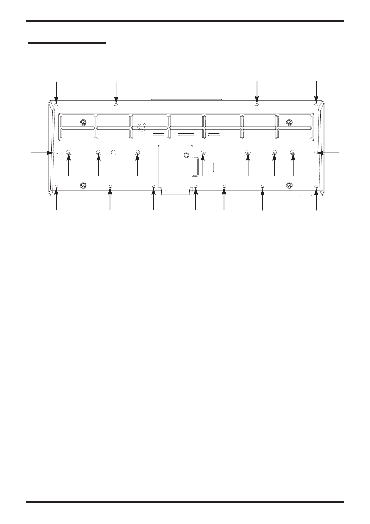
DISASSEMBLY
SCREW 2.9X13 TC BZ TFR T.7 TROP HILO #J2289274
Page 5

E-50
5
Page 6
E-50
Aug. 2006
7
6
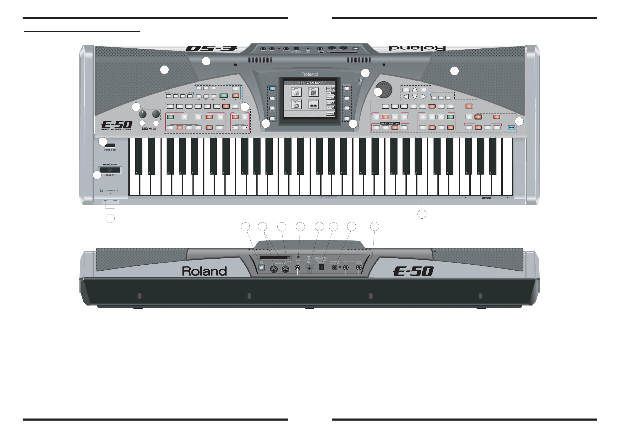
LOCATION OF CONTROLS
1
9
MIN MAX
A
MASTER
ACCOMP
6
7
RECORDER
PLAY
MINUS
NEXT
LIST
SONG
MARK JUMP
1 243
LIVE
8 BEAT
BAND
16 BEAT
BALANCEVOLUME
INTRO MAIN
KEYBOARD
B
VARIATION
123 4
DISCO
ROCK
DANCE
STYLE CONTROL
END/RIT
TOP
STYLE
BWD
BALL
ROOM
BASS
INVERS
AUTO
FILL IN
ONE
FWD
JAZZ
BLUES
START
STOP
SYNC
PLAY
STOP
LATIN
16-TRK
SEQ.
REC
TRADIT
WORLD
METRO
NOME
SLOW
TEMPO
DEFAULT
2
TAP
FAST
ASSISTANT
3
MUSIC
LYRICS &
SCORE
MIXER
PAGE
DISK &
MEDIA
SONG
STYL
MAKEUP
TOOLS
SONG
STYL
MENU
EXIT
LCD
21
CONTRAST
E
E
3
DATA ENTRY
5
NUMERIC PAD (PUSH)
ORGAN
PIANO
ACCORD
E.PIANO
USER PROGRAM
DOWN
HOLD
LIST
ARR ORGAN PIANO
CANCEL
GUITAR
GUITAR
BASS
INCDEC
FINDER
SAX
SYNTH
BRASS
KEYBOARD PART
SONG
TONE ASSIGN
PART ON / OFF
TONE
STRINGS
VOCAL
UP
STYLE
UP2 UP1MBS LWR
8
USER
PRG
PAD
DRUMS
SFX
DEMO
TONE EFFECTS TRANSPOSE
MELODY
MELODY
MULTI
MULTI
FX
FX
INTELL
INTELL
ONE TOUCH
1234
4
10
11
12
13
20
1514
16
17
18
19
Part No.
No.
1
K2478439 BLACK KNOB+WHITE INSERT E-80
00459901
A
B
13289186 RK11K1130 10KB LM1-15C W/CLK
2
K2478441 36-BUTTON GROUP (LEFT CONDUCT.PAD)E50/60
3
K2478442 4-BUTTON GROUP (CENTRAL COND.PAD) E50/60
4
K2478440 42-BUTTON GROUP (RIGHT COND.PAD) E50/60
5
K2478418 ENCODER BLACK KNOB G-70
Description
ROT. POT. 10KB 14K 1230
J3119105 ROTARY ENCODER EC12E24244F25
6
K2028148 SILK.+VARN. LCD COVER E-50
7
K2278105 LEFT SPEAKER GRILL E-50/E-60
8
K2278104 RIGHT SPEAKER GRILL E-50/E-60
3249559701 SWITCH CAP
9
J3129101 SWITCH SDKLA 11000
10
K3278112 PITCH BENDER SW + CABLE (36)+1C.
11
13449252 JACK SOCKET YKB 21-5006
12
01459945 USB SOCKET YKF45-0002
13
13429697 5P DIN SOCKET TCS5350-01-4051
14
03562156 FANTOM-X6 PC CARD BSCT BLK
15
J3139101 SWITCH SSAB110100
16
22365708 HOLDER F/POWER SUPPLY CBL
J3449104 DC SUPPLY SOCKET 2DC-0005G NL14007
17
13449126 JACK SOCKET HLJ0520-01-010
18
13449283 JACK SOCKET HLJ7101-01-3010
19
20
J2589110 61-KEY TP/7BA+C(DR) KEYBOARD 65074700
21
J3219110 ROT. POT. (10K) RK14J11A000G
Page 7
E-50
Aug. 2006
9
8
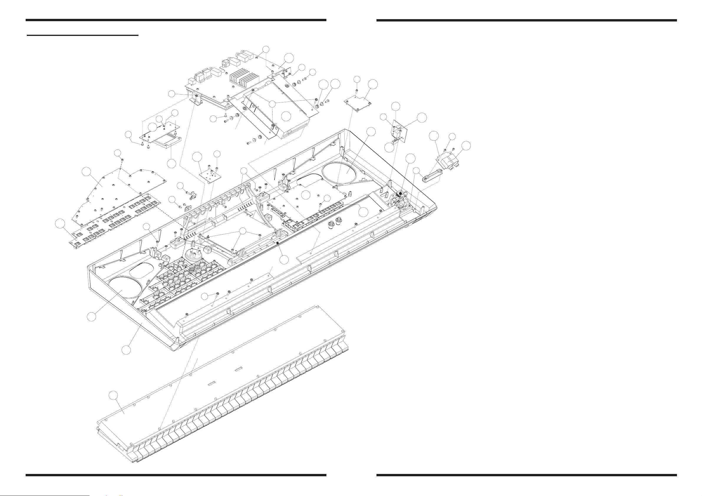
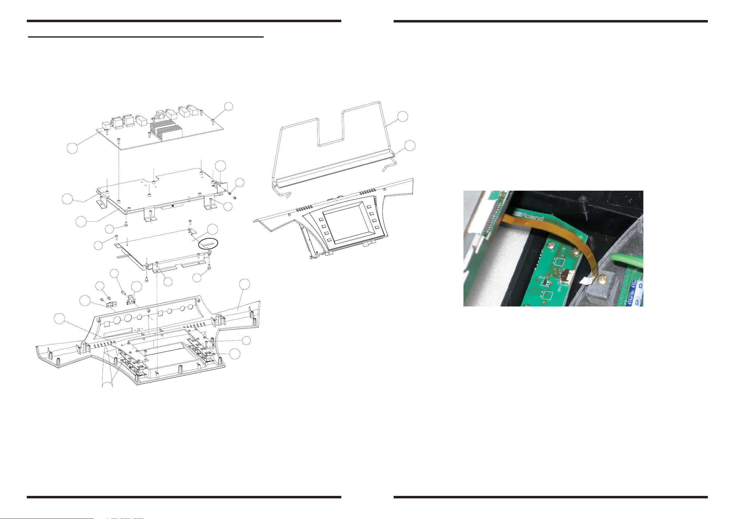
EXPLODED VIEW TOP
C
13
D
F
23
22
E
A
14
11
E
B
A
C
4
C
A
15
*
A
10
2
A
18
19
21
20
16
H
17
3
7
G
D
A
8
A
12
E
E
9
E
1
A
Part No.
No.
1
K2278104 RIGHT SPEAKER GRILL E-50/E-60
2
K2278105 LEFT SPEAKER GRILL E-50/E-60
3
02900867 CARD EJECTOR SCAB1A5600
4
7778109000 CARD PROTECT PCB ASSY E-50/E-60
5
J2589110 61-KEY TP/7BA+C(DR) KEYBOARD 65074700
6
7778203000 SILK.+VARN. TOP CABINET E-50
7
7778105000 RIGHT CONTROL PCB ASSY E-50/E-60
8
7778202000 LEFT CONTROL PCB ASSY E-50
K2248197 AD. FELT (WHITE) MM.860X7 TH.1.5
9
10
J240910801 FLOPPY DISK DRIVER ALPS DF354H148G
11
K2478440 42-BUTTON GROUP (RIGHT COND.PAD) E50/60
12
K2478441 36-BUTTON GROUP (LEFT CONDUCT.PAD)E50/60
13
7778103000 AUDIO PCB ASSY E-50/E-60
14
7778112000 VOLUME PCB ASSY E-50/E-60
15
7778108000 ENCODER ASSY E-50/E-60
16
7778110000 HEADPHONES PCB ASSY E-50/E-60
13449252 JACK SOCKET YKB 21-5006
17
18
3249559701 SWITCH CAP
7778111000 POWER SWITCH PCB ASSY E-50/E-60
19
20
J3129101 SWITCH SDKLA11000
21
K3278112 PITCH BENDER SW + CABLE (36)+1C.
22
22265242 RUBBER GUIDE BUSHING
23
22165134 BRASS BUSHING
Description
6
*
Screw
J2289126 SELF TAP.SCREW 2.9X 8 TCTCPRBZ
A
40342345 W SEMS W/WASHER M2*10 BZC
5
B
J2289193 SELF LOCK.SCREW M3X6 TC TC H.6
C
J2289101 SELF TAP.SCREW 2.9X 6 TC TC
D
J2289287 SCREW 2.9X13 TC PR BZ TFR H.7 HILO
E
J2289108 SELF LOCK.SCREW M3X10 TCTC H.6
F
J2289160 SELF TAP.SCREW 2.9X13 TCTCPR BR
G
J2289102 SELF TAP.SCREW 2.9X10 TC TC
H
Page 8
E-50
Aug. 2006
11
10
EXPLODED VIEW SILK.+VARN. LCD COVER
11
12
A
1
4
D
11
12
Pa rt No.
No.
1
7778103000 AUDIO PCB ASSY E-50/E-60
2
7778109000 CARD PROTECT PCB ASSY E-50/E-60
3
7778201000 MAIN BOARD PCB ASSY E-50
4
J3809164 RESISTOR 3.3 OHM 10W +HEATSINK
5
J5039111 LCD SP14Q006-ZZA+TOUCH PANEL
Note: When you substitute the LCD SP14Q006-ZZA+TOUCH PANEL #J5039111
pay attention to disconnect the cable from CN3 Connector CFP1504-0401F #04123090
on Center Control B. as shown :
Description
8
2
3
6
C
D
B
A
5
See Note
E
C
7
A
10
6
K2248193 PCMCIA SLOT ESCUTCHEON G-70
7
22365708 HOLDER F/POWER SUPPLY CBL
8
7778106000 CENTRAL CONTROL PCB ASSY E-50/E-60
K2478442 4-BUTTON GROUP (CENTRAL COND.PAD) E50/60
C
9
9
10
K2028148 SILK.+VARN. LCD COVER E-50
11
K2198121 BLACK VARNISHED MUSIC REST E-50/E-60
12
22208320 MUSIC SCORE HOLDER
9
Screw
J2289193 SELF LOCK.SCREW M3X6 TC TC H.6
A
J2289287 SCREW 2.9X13 TC PR BZ TFR H.7 HILO
B
J2289126 SELF TAP.SCREW 2.9X 8 TCTCPRBZ
C
J2289101 SELF TAP.SCREW 2.9X 6 TC TC
D
J2289160 SELF TAP.SCREW 2.9X13 TCTCPR BR
E
Page 9
Aug. 2006
12
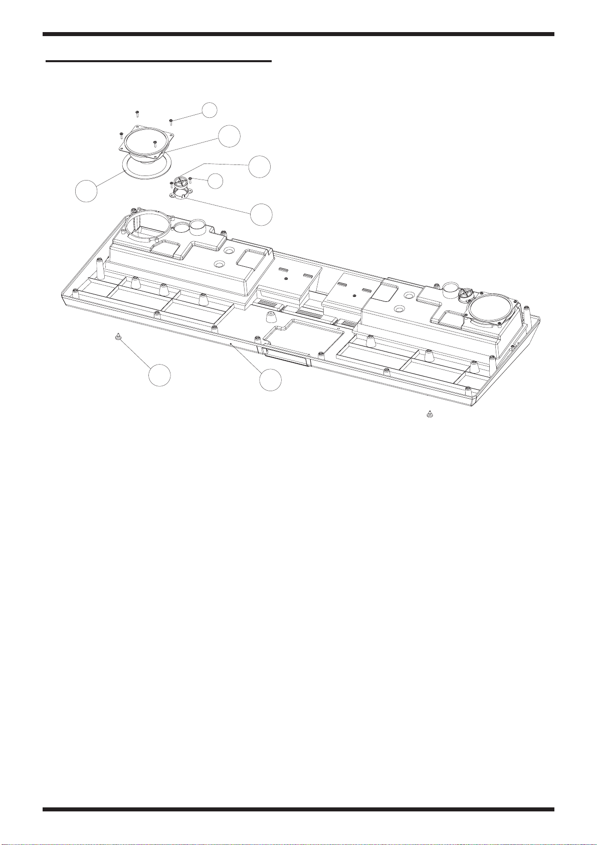
EXPLODED VIEW BOTTOM
A
5
4
A
6
3
1
Part No.
No.
1
K2358105 PRESSURE RUBBER FOOT
2
K2018131 SOUNDPROOFED BOTTOM CBNT+BOX E-50
3
K1188130 TWEETER SUPPORT EM2000/EG101
4
K2418131 TWEETER SPEAKER 4 OHM E-50/E-60
5
K2418130 WOOFER SPEAKER 4 OHM Z001401
6
K2228103 SPEAKER GASKET 108/88 TH.2
Screw
J2289287 SCREW 2.9X13 TC PR BZ TFR H.7 HILO
A
Description
2
Page 10

E-50
13
Page 11
E-50
Aug. 2006
15
14
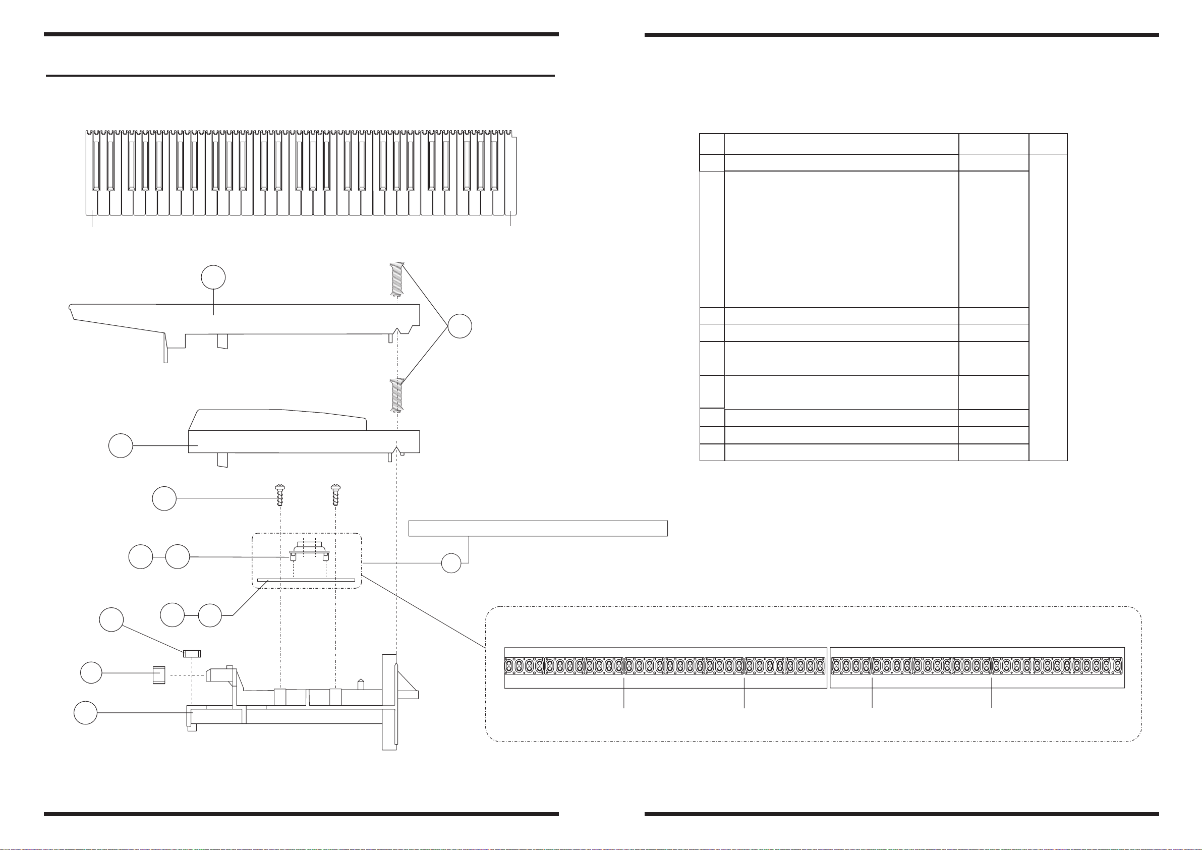
KEYBOARD PARTS LIST
DO
2
DO
N
PARTS NAME
O.
1
SPRING F/KEY 55 GR. No.118(23105270)
-
NATURAL KEY C5 DO
NATURAL KEY D6
NATURAL KEY E7
NATURAL KEY F1
2
NATURAL KEY G2
NATURAL KEY A3
NATURAL KEY B4
RE
MI
FA
SOL
LA
SI
CODE RJA
J2179116
J2579123 5
J2579124 5
J2579125 5
J2579126 5
J2579127 5
J2579128 5
J2579129 5
Num.
61
NATURAL KEY C8
SHARP KEY
1
3
3
SCREW 2,9x10 TCTCPR TROP
4
12P RUBBER CONTACT ADI-LR13/12(25640210)
5
13P RUBBER CONTACT ADI-LR13/13(25640220)
6
7
LEFT CONT. PCB ASSY+RUBBER 32 KEY (26043130)
RIGHT CONT. PCB ASSY+RUBBER 29 KEY (26043120)
8
KEYBOARD SUPPORT 61 KEYS
9
FELT FOR KEYBOARD ASSY
10
UPPER GUIDE BUSHING
11
DO(F)
J2579130
22578318 25
J2289125 34
J3169110 4
J3169111 1
J2929106
J2929105
22818746 1
2235815101
22158789 1
1
1
1
1
4
CONTACT BOARDS ARE COMPLETE WITH RUBBER CONTACTS
*
5
6
PM
SM
*
10
7
8
ASSEMBLY OF RUBBER CONTACT
11
8P 4P+
9
12P RUBBER CONTACT
12P RUBBER CONTACT
12P RUBBER CONTACT 12P RUBBER CONTACT 13P RUBBER CONTACT
Page 12
E-50
Aug. 2006
17
16
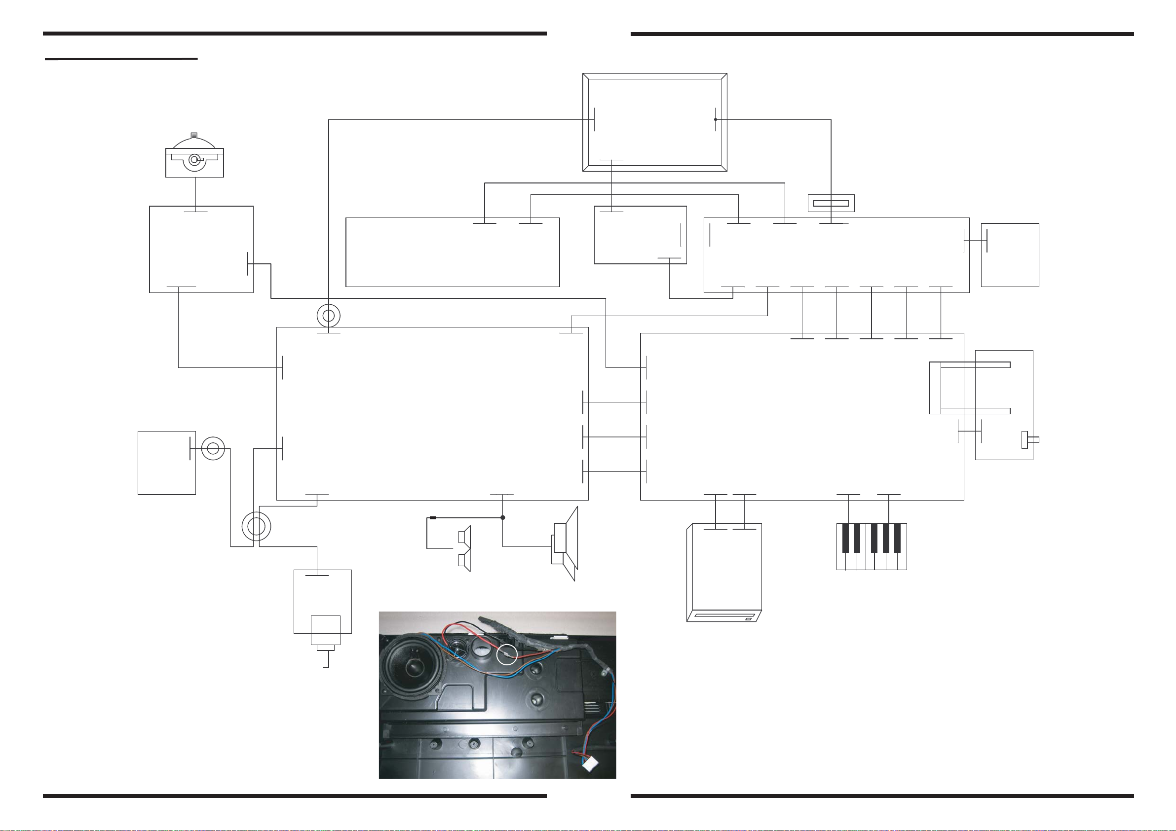
WIRING DIAGRAM
FASTON
Pitch-Bender
K3278112
VOLUME
BOARD
CN1
S6B-PH
6
CN101
B7B-PH
HEADPHONES
BOARD
6
53015-0610
CN3
7
3 TURNS
CN2
53015-0510
W1
1 TURN
5
W1
6
7
CN8
B6B-PH
CN32
B7B-PH
W1
W1
4
IL-G-4P-S3T2_E
CN16
5045-04A
4
13 9
B13B-PH
CN2
LEFT CONTROL BOARD
CN13
AUDIO BOARD
FASTON
4
CN38
5045-08A
8
W2
B9B-PH-SM4-TB
CN3
4
B4B-PH
CN37
7
CN31
B7B-PH
14 14
CN15
B14B-PH
7 7
CN33
B6B-PH
BackLight
LCD SP14Q006-ZZA
+
TOUCH PANEL
Touch
Panel
4
52207-0467
CN3
CENTER
CONT. B.
CN1
8-188275-6
(AMP)
CN2
B7B-PH
7
W1
5
CN21
53014-0510
W1
7
CN31
B7B-PH
W1
CN14
B14B-PH
W1
CN7
B6B-PH
LCD SP14Q006-ZZA+TOUCH PANEL
J5039111
CN4
B4B-PH
139
B13B-PH
CN10
W1
CN1
B15B-PH
15
LCD Signals
15
B15B-PH
53014-1510
CN2
14
006207341914000
CN2
CN7
B12B-PH
12
SW/LED
12
B12B-PH
CN22
1 TURN
CN8
B8B-PH
8
B8B-PH
CN23
W1
W7
1616
CN9
8-188275-6
(AMP)
7
W1
B9B-PH
CN6
RIGHT CONTROL BOARD
CN3
B7B-PH
4
MAIN BOARD
CN9
CN33
B4B-PH
34
4
W3 W4 W6 W5
CN35
AMPC1.2716P
22
SW/LED
CN36
AMPC1.2716P3m_34p
16
55
CN11
B5B-PH
CN12
B3B-PH
3
8
Encoder
3
B3B-PH
CN12
CN5
B6B-PH
6
6
B6B-PH
CN18
Touch Screen
W1W1W1W1W1
W1
CN1
S5B-PH
ENCODER
BOARD
CARD
PROTECT
BOARD
3
5
W1
CN32
53014-0310
SW1
CN32
53014-0310
SDKLA11000
J3129101
4
5045-04A
CN1
POWER
SWITCH B.
Tweeter 4 Ohm (NO CAP)
K2418131
FASTON
4
Woofer 4 Ohm 2155
K2418130
CN38
5045-08A
W2
Keyboard
FLOPPY
DRIVER
ALPS DF354H148G
J240910801
W
Code Description Qty
W1
7778206000 3P CABLE ASSY 2N/1R (10) 4P CONNEC. 1
W2
K3468302 8P CABLE (RES+BLACK/BLACK+BROWN)-1C P2.5 1
7778206000 3P CABLE ASSY 2N/1R (10) 4P CONNEC. 1
W3
K3468203 34P FLAT CABLE (12) -2C 1
W4
2348854501 16P FLAT CABLE (18) -2C D/R 1
W5
K3468234 16P FLAT CABLE ASSY (28) -2C 1
W6
K3468189 16 FLAT CABLE (16) -2C 1
W7
61-KEY TP/7BA+C(DR) KEYBOARD 65074700
J2589110
61 Keys
Page 13
Aug. 2006
18
CASING Q.ty
# K2278104 RIGHT SPEAKER GRILL E-50/E-60 1
# K2278105 LEFT SPEAKER GRILL E-50/E-60 1
# K2018131 SOUNDPROOFED BOTTOM CBNT+BOX E-50 1
# K2028148 SILK.+VARN. LCD COVER E-50 1
# 7778203000 SILK.+VARN. TOP CABINET E-50 1
# K2198121 BLACK VARNISHED MUSIC REST E-50/E-60 1
22208320 MUSIC SCORE HOLDER 1
KNOB BUTTON
K2478418 ENCODER BLACK KNOB G-70 1
K2478439 BLACK KNOB+WHITE INSERT E-80 2
3249559701 SWITCH CAP 1
# K2478440 42-BUTTON GROUP (RIGHT COND.PAD) E50/60 1
# K2478441 36-BUTTON GROUP (LEFT CONDUCT.PAD)E50/60 1
# K2478442 4-BUTTON GROUP (CENTRAL COND.PAD) E50/60 2
SWITCH
J3129101 SWITCH SDKLA11000 SW1 on Power Switch B. 1
# J3139101 SWITCH SSAB110100 1
JACK, SOCKET
J3449104 DC SUPPLY SOCKET 2DC-0005G NL14007 JK5 on Audio B. 1
13449252 JACK SOCKET YKB 21-5006 JK11,JK12 on Card Protect B. 2
13449126 JACK SOCKET HLJ0520-01-010 JK2 on Audio B. 1
13449283 JACK SOCKET HLJ7101-01-3010 JK3,JK4,JK8 on Audio B. 3
13429697 5P DIN SOCKET TCS5350-01-4051 JK6,JK11 on Audio B. 2
01459945 USB SOCKET YKF45-0002 JK10 on Audio B. 1
DISPLAY UNIT
# J5039111 LCD SP14Q006-ZZA+TOUCH PANEL 1
DISK DRIVE UNIT
NNoottee :: J240910801 FLOPPY DISK DRIVER ALPS DF354H148G 1
BENDER UNIT
NNoottee :: K3278112 PITCH BENDER SW + CABLE (36)+1C. 1
SPEAKER
# K2418131 TWEETER SPEAKER 4 OHM E-50/E-60 2
# K2418130 WOOFER SPEAKER 4 OHM Z001401 2
KEYBOARD ASSY
J2589110 61-KEY TP/7BA+C(DR) KEYBOARD 65074700 1
NOTE: For details, refer to KEYBOARD PARTS LIST
PCB ASSY
# 7778201000 MAIN BOARD PCB ASSY E-50 1
# 7778103000 AUDIO PCB ASSY E-50/E-60 1
# 7778105000 RIGHT CONTROL PCB ASSY E-50/E-60 1
# 7778202000 LEFT CONTROL PCB ASSY E-50 1
# 7778106000 CENTER CONTROL PCB ASSY E-50/E-60 1
# 7778112000 VOLUME PCB ASSY E-50/E-60 1
# 7778108000 ENCODER ASSY E-50/E-60 1
# 7778109000 CARD PROTECT PCB ASSY E-50/E-60 1
# 7778110000 HEADPHONES PCB ASSY E-50/E-60 1
# 7778111000 POWER SWITCH PCB ASSY E-50/E-60 1
PARTS LIST
NOTE:
# The parts marked " # '' are new (Initial Parts).
A The parts marked " A '' are new (Initial Parts).for RES but already used by RJA
The parts marked have Safety - Related characteristics.
Use only listed parts for replacement.
<< EMI >> Component for EMC.
NNoottee :: Replacement should be made on a unit basis. No replacements available for individual parts.
Replacement only be a unit.
Page 14

E-50
19
IC
# 03674545 I.C. K4S561632H-UC75 FLAT IC7 on Main B. 1
# J5159120 I.C. TC74VHC08FT(EL) IC6 on Main B. 1
# J5159122 I.C. LA4601N-E (RoHS) IC35 on Audio B. 1
# J5259196 I.C. 74LV20ATELL-E FLAT IC342,IC344 on Main B. 2
# J5259197 I.C. 74LV573ATELL-E FLAT IC3,IC5 on Main B. 2
# J5259198 I.C. TA2024B FLAT IC1 on Audio B. 1
A 03561112 I.C. TC7SH14FU(T5L, F, T) FLAT IC38 on Main B. 1
# J5259199 I.C. TC 74VHCT32AFT(EL) FLAT IC43 on Main B. 1
K5258186 I.C. 74 HC 238 FLAT IC4 on Right Control B. 2
IC3 on Left Control B.
J5259161 I.C. M66291GP USB CONTROLLER IC133 on Main B. 1
03344445 IC MX3000AS IC8 on Audio B. 1
01455312 I.C. TC7WH74FU IC91 on Main B. 1
01348945 I.C. TC7SH32FU FLAT IC21 on Main B. 1
00236845 I.C. TC 74VHC245F IC3 on Right Control B. 2
IC2 on Left Control B.
J5259135 I.C. TC 74VHC175FT IC79 on Main B. 1
J5259175 I.C. TC 7SH04FU (TE85L.J) IC52,IC63,IC64,IC336 on Main B. 4
01455301 I.C. TC7WH04FU (TE12L) FLAT IC33,IC35 on Main B. 2
J5259142 I.C. TC74VHCT138AF FLAT IC2 on Right Control B. 2
IC1 on Left Control B.
J5259145 I.C. TC7WH08FU FLAT IC338 on Main B. 1
J5259147 I.C. TC7WU04FU FLAT IC10,IC18,IC347 on Main B. 3
02565212 I.C. SN74LV245A-PW IC8,IC11,IC30,IC335 on Main B. 4
J5259157 I.C. TC74VHCT245AFT FLAT IC49,IC88,IC89,IC93 on Main B. 4
15269214 I.C. 74LS05 FLAT TTL IC2 on Audio B. 1
15189210 I.C. BA 5218F (OP AMP) IC16,IC43,IC44,IC45,IC46 11
IC47,IC48,IC49,IC50,IC51 on Audio B.
IC1 on Right Control B.
15289105 I.C. UPC 4570G (OP AMP) IC26 on Main B. 1
15199937 I.C. M51953 BFP FLAT IC10 on Audio B. 1
00458312 I.C. NJM 2360M FLAT IC13 on Main B. 2
IC17on Audio B.
15289141 I.C. M5223FP-600D IC51 on Main B. 2
IC5 on Right Control B.
J5199110 I.C. L4940V5 IC14 on Audio B. 1
01458445 I.C. UPC29M33T-T1 FLAT (REGULATOR) IC16,IC60 on Main B. 2
J5259133 I.C. TA7805 AF IC24 on Main B. 1
J5259163 I.C. LP2950 CZ-3.3 IC2 on Audio B. 1
# 7778204000 I.C. FLASH 512M IC4 CPU E-50/E-60 IC 4 on Main B. 1
# 7778207000 I.C. FLASH IC2 CPU E-50 IC2 on Main B. 1
# J5259194 I.C. HD6417706F133V IC1 on Main B. 1
J5259177 I.C. TC7SH08FU FLAT IC14,IC124,IC341 on Main B. 3
J5259186 I.C. PQ070XZ01ZPH IC15 on Main B. 1
02455212 IC (CUSTOM) SLAC02AF2H (KSM) KEY SCAN IC22 on Main B. 1
A 02908656 IC AK4382AVT-E2 FLAT IC25 on Main B. 1
# J5259192 I.C. TC74VHC138FT(EL) FLAT IC31 on Main B. 1
# J5159121 I.C. TC74VHC32FT(EL) IC48 on Main B. 1
# J5169109 I.C. 74LV4051ATELL-E IC56 on Main B. 1
# J5259189 I.C. HD74LV32ATELL-E IC80,IC92,IC94 on Main B. 3
# J5259191 I.C. TC74VHC139FT(EL) IC81,IC85 on Main B 2
# J5259188 I.C. 74LV21ATELL-E IC82,IC127 on Main B. 2
J5159117 I.C. TC74LVX4245FS(EL) IC86,IC87 on Main B. 2
J5259190 I.C. HD74LV00ATELL IC90 on Main B. 1
02677490 IC TC203C180AF-003 FLAT IC106 on Main B. 1
03787889 I.C. M11L416256SA-35T IC111 on Main B. 1
# J5259193 I.C. S1D13705F00A200 IC125 on Main B. 1
# J5259195 I.C. ROM TC58DVM72A1TG00BBH FLAT IC126 on Main B. 1
02568456 I.C. FDC37C78 IC152 on Main B. 1
# J5259187 I.C. P2027AF-08TR IC339 on Main B. 1
TRANSISTOR
00901523 TRANSISTOR 2SA-1681K Q14,Q32,Q45 on Audio B. 3
02671023 TRANSISTOR 2SC-3052 Q13,Q15,Q34 on Audio B. 3
02671267 TRNSISTOR RT1N141C-T12-1 Q12,Q33 on Audio B. 2
# J5119112 TRANSISTOR SSM3J02T(TE85L, F) CHIP Q7 on Main B. 1
# J5119113 TRANSISTOR RN1426 Q8,Q9,Q10,Q11,Q12,Q13 16
Q14,Q15,Q16,Q17,Q18,Q19,
Q20,Q21 on Right Control B.
Q9,Q10,Q11,Q12,Q13,Q14,
Q15,Q16 on Left Control B.
# J5119114 TRANSISTOR RN1308(TE85L,F) Q7 on Audio B. 1
# J5119115 TRANSISTOR RN2307(TE85L,F) CHIP Q5 on Audio B. 1
15129114 TRANSISTOR 2SC-1815GR Q1,Q6 on Audio B. 2
15119113 TRANSISTOR 2SA-1015 GR Q3,Q9 on Audio B. 2
15319101 TRANSISTOR 2SC-2412K Q31,Q38,Q39 on Audio B. 3
15309101 TRANSISTOR 2SA-1037KR Q22 on Right Control B. 1
15319105 TRANSISTOR 2SC-3326A Q2,Q8,Q10,Q11,Q41,Q42, 8
Q43,Q44
J5119104 TRANSISTOR DTA-114 EK CHIP Q2,Q5 on Right Control B. 2
# J5119116 TRANSISTOR DTA-114 EVA CHIP Q4 on Audio B. 1
# J5119117 TRANSISTOR DTC-114 EVA CHIP Q8,Q9,Q10 on Main B. 3
15319107 TRANSISTOR 2SC-4116GR Q4,Q7 on Right Control B. 2
02451378 TRANSISTOR RN2427 Q8,Q9,Q10,Q11,Q12,Q13 on Right Control B. 11
J5119107 TRANSISTOR 2SA-1586-GR (TE85R) Q1,Q3,Q6 on Right Control B. 3
Page 15

Aug. 2006
20
15129623 TRANSISTOR 2SD-667C Q18 on Audio B. 1
DIODE
01897189 DIODE MA147-(TX) CHIP D8 on Main B. 6
D5,D10,D25,D26,D28 on Audio B.
J5019123 DIODE SCHOTTKY SK13 CHIP D2,D4,D6,D8 on Audio B. 4
A 02780401 CEA SCHOTTKY DIODE MA720-(TX) D1 on Main B. 2
D27 on Audio B.
# J5029125 LED DIODE SML-012UTT86A RED SMD D1,D3,D4,D5,D6,D8,D9, 62
D11,D12,D13,D14,D15,D16,
D17,D19,D20,D22,D23,D24,
D25,D27,D28,D29,D30,D31,
D32,D33 on Right Control B.
D1,D2,D3,D4,D5,D6,D7,D8,
D9,D10,D11,D12,D13,D14,
D15,D17,D18,D19,D20,D21,
D22,D24,D25,D26,D27,D28,
D29 on Left Control B.
D1,D2,D3,D5,D6,D7,D8 on Center Control B.
# J5029126 LED DIODE SML-012BCTT86 BLUE SMD D34 on Right Control B. 2
# J5029127 LED DIODE SML-012ECTT86 GREEN SMD D2,D10,D18,D26 on Right Control B. 9
D16,D23,D30,D50,D52 on Left Control B.
D31,D32,D33,D34,D35,D36,
D37,D38,D39,D40,D41,D42,
D43,D44,D45,D46,D47,D48 on Left Control B.
15339109 DIODE DAP 202K CHIP D13 on Audio B. 45
D35,D36,D37,D38,D39,D40,
D41,D42,D43,D44,D45,D46,
D47,D48,D49,D50,D51,D52,
D53,D54,D55,D56 on Right Control B.
D9,D10,D11,D12 on Center Control B.
01121323 DIODE DA-204U T-106 CHIP D3,D4,D5,D6,D7 on Main B. 5
00019356 DIODE 1SR139-400 T-32 D17 on Audio B. 1
01905134 SCHOTTKY DIODE MA7D49 D24 on Audio B. 1
RESISTOR
# J3919119 RESISTOR ARRAY EXB28V103JX RA18,RA21,RA24,RA26,RA41, 14
RA46,RA95,RA100,RA140,
RA141,RA142,RA143,RA144,
RA145 on Main B.
# J3919120 RESISTOR ARRAY EXB2HV330JV RA2,RA35,RA36,RA39,RA42, 14
RA113,RA114,RA115,RA116,
RA117,RA150,RA151,RA152,
RA153 on Main B.
# J3919121 RESISTOR ARRAY EXB2HV103V RA9,RA14,RA31,RA44,RA118, 6
RA119 on Main B.
# J3919122 RESISTOR ARRAY EXB28V330JX RA16,RA17,RA22,RA23,RA27, 19
RA29,RA33,RA37,RA38,RA45,
RA47,RA128,RA135,RA136,
RA137,RA138,RA139,RA154,
RA155 on Main B.
# J3919123 RESISTOR ARRAY EXB2HV104JV RA129,RA130,RA131 on Main B. 3
# J3919124 RESISTOR ARRAY EXB-2HV-R00-0V RA4,RA7,RA11,RA19,RA30, 9
RA32,RA34,RA146,
RA147on Main B.
# J3919125 RESISTOR ARRAY EXB-2HV-102-JV RA127 on Main B. 1
J3919104 RESISTOR ARRAY EXB-A10E-103-J RA3 on Right Control B. 2
RA3 on Left Control B.
J3919108 RESISTOR ARRAY EXB-V8V-103-JV RA65,RA134 on Main B. 2
J3919116 RESISTOR ARRAY EXB-V8V-220-JV RA106 on Main B. 8
RA1,RA2,RA4 on Right Control B.
RA1,RA2,RA4,RA5 on Left Control B.
01457145 RESISTOR ARRAY EXB-E10C-103-J RA1,RA8,RA40,RA43,RA50, 16
RA52,RA57,RA90,RA91,RA92,
RA93,RA96,RA112,RA120,
RA121,RA122 on Main B.
02456878 RESISTOR ARRAY EXB-2HV-220-JV RA108,RA124,RA125,RA126 on Main B. 4
J3809156 UNINFL. RES. 47 OHM 0.6W 5% R238,R239 on Card Protect B. 4
J3809162 METAL OXIDE RESIST.120 OHM 2W10% R66,R69,R93 on Audio B. 3
# J3809164 RESISTOR 3.3 OHM 10W +HEATSINK R228 on Audio B. 1
J3709168 RESISTOR 2010 1 OHM 1/2W 5% (MCR50) R126 on Audio B. 1
01783623 RESIST. 2010 10 OHM1/2W 5% R247 on Main B. 6
R6,R7,R118 on AudioB.
R15 on Right Control B.
# J3709170 RESISTOR 2010 0.22OHM 1/2w 5% (MCR50) R64 on Main B. 1
# J3709171 RESIST. 2010 22 OHM1/2W 5% R24 on Right Control B. 2
# J3709172 RESISTOR 2010 33 OHM 1/2W 5% (MCR50) R292 ON Main B. 15
R17,R18,R19,R20,R21,R22,
R23 on Right Control B.
15399989 RESIST. 2010 68 OHM1/2W 5% R19,R30 on Audio B. 2
POTENTIOMETER
00459901 ROT. POT. 10KB 14K 1230 VR1 on Volume B. 1
J3219110 ROT. POT. (10K) RK14J11A000G VR1 on Center Control B. 1
13289186 RK11K1130 10KB LM1-15C W/CLK VR2 on Volume B. 1
Page 16

E-50
21
CAPACITOR
15359774 POLYEST.COND. 0805 680P 5% C157,C171,C187,C203 on Main B. 4
J3629144 ELCTRL.COND. 470UF 16V AX C3 on Left Control B 1
13639154 ELECTRL.COND.-V 1000UF 16V C28,C142,C154,C189,C191 on Audio B. 5
13639153RI ELECTRL.COND.-V 470UF 16V C8 on Right Control B. 1
J3629122 ELECTRL.COND.-V 1000UF 25V C190 on Audio B. 1
J5369103 ELECTR.CAPACITOR RV2 100U 16V (SMD) C74,C235,C401 on Main B. 17
C1 on Right Control B.
J5369104 ELECTR. COND. RV2 10U 16V (SMD) C145,C241,C491on Main B. 18
C41,C43,C44,C45,C65,C85,
C103,C125,C136,C221,C265,
C266,C306,C307 on Audio B
J5369107 ELECTR. COND. RV 330U 16V (SMD) C487 on Main B. 2
C141 on Audio B.
J5369105 ELECTR.CAPACITOR RV3 33U 16V (SMD) C21,C26,C31,C34,C51,C80, 27
C83,C84,C87,C168,C183,
C200,C202,C254,C255,C270,
C273,C456,C476 on Main B.
C36,C254,C255 on Audio B.
C2,C3,C7,C14 on Right Control B.
C2 on Left Control B.
J5369102 ELECTR.COND. RV2 47U 16V SMD C66,C69,C75,C80,C81,C87, 15
C116,C129,C155,C156,C161,
C267,C268,C269,C270 on Audio B.
J5369111 ELECTR. COND. RV2 10U 25V (SMD) C150,C157,C194,C195 on Audio B. 5
J5369108 CONDENSER SMD RV2 4.7U 25V ELET. ELNA C193 on Audio B. 2
C4 on Right Control B.
J5369106 ELECTR. COND. RV2 1U 50V (SMD) C56 on Main B. 5
C123,C124,C259,C308 on Audio B.
J3629137 ELECTR. COND. 33U 16V H.7 C3 on Volume B. 1
J3629172 CAPACITOR ECJ3FB1C105K C7,C24 on Audio B. 2
J3629173 ELECTR. CAPACITOR EEUFC1E181B 180UF 25V C2,C23 on Audio B. 2
INDUCTOR, COIL, FILTER
12449382RI NOISE SUP. PLT1-R53C FL4 on Audio B. 1
J2399104 CHIP NOISE SUP. EXCCL4532U1 L57,L58 on Audio B. 2
12449355 NOISE SUP. FBR07H850TB00 L40,L41 on Card Protect B. 2
01340834 FERRITE BEAD EXCML 20A390 L1,L2,L44,L45,L46,L47 on Audio B. 6
A 01787056 N1608Z 102T01 FERRITE-BEAD L1,L3,L16,L23,L24,L25, 43
L27,L28,L29,L30,L31,L32,
L33,L34,L37,L38,L50,L52,
L95,L96,L97,L98,L99,L100,
L101,L102,L103,L104,L105,
L106,L107 on Main B.
L8,L13,L37,L38,L48,L49,
L50,L52,L53,L54,L55,L56
L12,L14,R37,R43,R47,R75 on Audio B.
01909645 FERRITE BEAD EXCML16A270U L17,L19 on Main B. 2
A 01565578 NOISE SUPPRESSOR N1608Z601T01 L18,L21 on Main B. 2
A 01893634 INDUCTOR LQH43MN151K03L 150uH CHIP L12 on Main B. 2
L16 on Audio B.
# J2399113 INDUCTOR RCB0708P-100K-LF L3,L4,L5,L6 on Audio B. 4
CRYSTAL, RESONATOR
A 02561712 CEM X'TAL MA-406 12.500 MHZ TE24 X1,X3 on Main B. 2
00901912 X-TAL 24.576 MHZ MA-406 X2 on Main B. 1
00891801 QUARTZ 24 MHZ MA-406 X6 on Main B. 1
01340745 XTAL MA-406 12MHZ X4 on Main B. 1
J2389104 RESONATOR CSTLS4M00G53-BO (4MHZ) X2 on Audio B. 1
ENCODER
J3119105 ROTARY ENCODER EC12E24244F25 ENC1 on Encoder B. 1
CONNECTOR
J3439197 14P MALE CONNECTOR B14B-PH-K-S JST CN14 on Main B. 2
CN15 on Audio B.
13369567 4P MALE CONNECTOR B4B-PH-K-S (JST) CN13,CN30,CN33 on Main B. 4
CN37 on Audio B.
A 02900834 CONNECTOR SCAA1A4900 CN29 on Main B. 1
J3439206 15P MALE CONN. B15B-PH-K-S (JST) CN2 on Main B. 1
J3439208 6P MALE CONNECTOR(90) S6B-PH-K-S P.2 JST CN1 on Volume B. 1
J3429132 16P FEM.CONNECTOR AMP1.27 8-188275-6 CN9 on Right Control B. 2
CN1 on Center Control B.
J3439209 MALE CONNECTOR 5V.90°S5B-PH-K-S P.2 JST CN1 on Encoder B. 1
04123090 CONNECTOR CFP1504-0401F CN3 on Center Control B. 1
00451401 16P FEM. CONNECTOR AMP 1.27 CN35,CN36 on Main B. 2
13419676RI 8P MALE CONN. P/2.5 MOLEX CN38 on Audio B. 1
13369688RI 4P MALE CONN. P 2.5 M CN1 on Power Switch B. 2
CN16 on Audio
J3439125 5P MALE CONNECTOR P.2 M CN21 on Main B. 1
J3439143 34P MALE CONN. P. 1.27 M CN11 on Main B. 1
J3439123 6P MALE CONN. P. 2 M 90 CN3 on Volume B. 1
J3429120 3P MALE CONNECTOR P.2 M CN32 on Main B. 2
13369568 B3B-PH-K-S CONNECTOR CN12 on Main B. 1
13369566 B6B-PH-K-S CONNECTOR CN7,CN18 on Main B. 4
Page 17

Aug. 2006
22
CN8,CN31 on Audio B.
13369503 B7B-PH-K-S CONNECTOR CN31 on Main B. 4
CN101 on Card Protect B.
CN31,CN32 on Audio B.
13369564 B12B-PH-K-S CONNECTOR CN22 on Main B. 1
J3439182 5P MALE CONNECTOR 90 P.2 M CN2 on Volume B. 1
J3439178 4P MALE CONNECTOR IL-G-4P-S3T2-E CN13 on Audio B. 1
J3439189 8P MALE CONNECTOR B8B-PH-K-S P.2 JST CN23 on Main B. 1
WIRING, CABLE
# K3468302 8P CABLE (RES+BLACK/BLACK+BROWN)-1C P2.5 1
K3468189 16 FLAT CABLE (16) -2C 1
# K3468234 16P FLAT CABLE ASSY (28) -2C 1
K3468203 34P FLAT CABLE (12) -2C 1
# 7778206000 3P CABLE ASSY 2N/1R (10) 4P CONNEC. 1
2348854501 16P FLAT CABLE (18) -2C D/R 1
# 7778205000 WIRE STRAND E-50 1
SCREW
J2289122 SCREW 2.2X6 TC TC BRUN 2
J2289101 SELF TAP.SCREW 2.9X 6 TC TC 4
J2289102 SELF TAP.SCREW 2.9X10 TC TC 2
J2289126 SELF TAP.SCREW 2.9X 8 TCTCPRBZ 69
J2289125 SCREW 2.9X10 TC TC PR TROP 34
J2289160 SELF TAP.SCREW 2.9X13 TCTCPR BR 1
J2289108 SELF LOCK.SCREW M3X10 TCTC H.6 6
J2289193 SELF LOCK.SCREW M3X6 TC TC H.6 22
J2289274 SCREW 2.9X13 TC BZ TFR T.7 TROP HILO 20
J2289287 SCREW 2.9X13 TC PR BZ TFR H.7 HILO 47
# 40342345 W SEMS W/WASHER M2*10 BZC 4
PACKING
K2678102 POLYETH. ENVELOPE 25X45 1
K2678105 CARTENE ENVELOPE HD 140X57 1
K2678106 POLYETH.ENVELOPE 40X55 1
# K2638340 RIGHT LDPE PROTECTION E-50 1
# K2638341 LEFT LDPE PROTECTION E-50 1
# K2638342 CENTRAL LDPE PROTECTION E-50 1
# K2638343 ADHESIVE LDPE WEDGE E-50/E-60 1
# K2668107 DIE-CUT CARDB0ARD SHEET 450X1153 1
# K2618330 OUTER PACKAGE E-50 1
MISCELLANEOUS
J2289113 NUT 3MA H.3 2
J2139101 FLAT WASHER I/D 4 4
J2139102 TOOTHED WASHER I/D 3 2
22165134 BRASS BUSHING 4
J2359101 SPACER 3M ART. SJ5012 1
22265242 RUBBER GUIDE BUSHING 4
K2358105 PRESSURE RUBBER FOOT 4
J2369101 SPECIAL LOCK I/D 4 3
J3469144 COPPER ADHESIVE STRIP 1
K2228103 SPEAKER GASKET 108/88 TH.2 2
2235815101 FELT FOR KEYBOARD ASSY 1
# K2248197 AD. FELT (WHITE) MM.860X7 TH.1.5 1
13429823RI P. SUPPLY PLUG LOCKING 1
22365708 HOLDER F/POWER SUPPLY CBL 1
K1188130 TWEETER SUPPORT EM2000/EG101 2
# K2268209 ADHESIVE FELT (BLACK) MM.280X13X1 4
13429823RI P. SUPPLY PLUG LOCKING 1
03562156 FANTOM-X6 PC CARD BSCT BLK 1
K2248193 PCMCIA SLOT ESCUTCHEON G-70 1
A 02900867 CARD EJECTOR SCAB1A5600 1
ACCESSORIES
# K6018644 PARAMETER REFERENCE E-50/E-60 1
K6018636 OWNER'S MANUAL (E) E-50/E-60 1
K6018646 OWNER'S MANUAL (F) E-50/60 1
K6018645 OWNER'S MANUAL (G) E-50/60 1
# K6018647 SERVICE NOTES E-50 1
# K2378138 CD-ROM DRIV./USB/O.M/BCK-UP DATA E50 E60 1
K244811503 SWITCHING ADAPTER SA165A-1250U-3 PSB-4U 1
J3439188 AC CORD 230V FOR ADAPT.SA165A-1250U (only for 230V) 1
J3439190 AC CORD 117V FOR ADAPT.SA165A-1250U (only for 117V 117V-US) 1
J3439210 AC CORD 240VA F/PSB-4U (INSULATED PIN) (only for 240VA) 1
J3439192 AC CORD 230VE FOR ADAPT.SA165A-1250U (only for 230VE) 1
Page 18

E-50
23
Page 19

Aug. 2006
24
d
e
f
g
h
i
j
k
c
TEST MODE
IItteemmss rreeqquuiirreedd
cc 2 SWITCH PEDAL (i.e. DP-8)
1 EXPRESSION PEDAL (i.e. EV-5)
PERSONAL COMPUTER
ROLAND RH-50 HEADPHONES
TOUCH SCREEN PEN
3 TEST DISKS: 1 for DD – 1 for HD – 1 for HD PROTECTED (for FDC tests)
2 PCMCIA CARDS 128MB: 1 for test – 1 for NAND FLASH (+ possible OPERATION SYSTEM)
1 MIDI CABLE
1 USB CABLE
1.1 How to enter the INTERNAL TEST mode
Keep the buttons MUSIC ASSISTANT, COVER, MAKEUP TOOLS pressed and turn on the E-50
N.B. The performance of the tests is checked by the E-50, it is therefore necessari to perform them
some cases.In any case to pass to one test (without performing it) to another at any moment, keep the button ONE TOUCH 1 pressed and then press the
VARIATION 1 button pressed.
all, otherwise it will not be possibile to continue in
Page 20

E-50
25
c
d
e
f
g
g
1.2 Touch Screen Calibration
Enter the “INTERNAL TEST” mode (cf. paragraph 1.1)
Wait for the initialization of the E-50 to start.
Using the touch screen pen, touch for a second, the points shown on the display, the sequenze is the following:
down on the left
up on the right
down on the right
up on the left
If the operation is not successful, the display shows NG:Calibration, in that case repeat the operation from scratch (point 3): after the error
message wait until the calibration video appears again
If the operation is successful, the display will show Calibration OK and after a while the instrument will pass to the next test.
4 2
d e
1
Page 21

Aug. 2006
26
c
d
e
f
c
e
f
1. Protect Switch Test
Make sure that the display shows Unprotect with the switch in the “NON PROTECTED” position.
Make sure that the display shows Protect with the switch in the “PROTECTED” position.
If both conditions have occurred the “marking” symbol will appear to confirm the positive outcome of the test.
Press the icon NE T to pass to the next test.
ATTENTION Before covering the switch with its cap, make sure that you have left it on the “PROTECTED” position.
d
Page 22

E-50
27
1.4 Version
c The video will show the information on the versions installed.
MUSICAL DATA
missing
d Check that the data of the versions match with the la test updates available; if the version of the Musical Data is not displayed, it means that the
loading of the data has not been carried out.
e Press the icon NEXT to pass to the next test.
Attention The images shown are only examples, the version numbers may change in time.
MUSICAL DATA
present
Page 23

Aug. 2006
28
1.5 Touch Screen Check
c Using the Touch Screen pen, touch all 10 squares outlined on the display or trace a diagonal line from top to bottom
d If the Touch Screen works correctly, each square touched will be coloured in grey.
c d
e After having touched all the squares the instrument will automatically pass to the next test.
Page 24

E-50
29
1.6 LCD display Check
c Each of the four buttons of the TONE section flashing (PIANO E. PIANO, ORGAN ACCORD, GUITAR BASS, STRINGS VOCAL) is associated
with a test for the LCD; press them one at a time and check that the LCD works correctly.
Chec that all pi els are
d In the 4th image, ad just the potentiometer LCD CONTRAST (on the right of the LCD tower) until you find a good contrast condition.
e At the end of the four tests, press the icon NEXT, to pass to the next test.
off
Chec that all pi els are
on
Chec the brightness and
separation of colours
Chec the brightness and
separation of colours
Page 25

Aug. 2006
30
1.7 Switch and Led Check
c From the previous test the display shows:
d Press one at a time all the buttons, respecting the sequenze shown in the figure below; the display shows the button to be pressed each time
and, if any, the associated led flashes.
e Make the following checks for each button:
a “beep” will be heard to confirm it is working correctly
the counter on the display will start growing when the button is released
in case of error a louder “beep” will be heard (buttons in short-circuit) or no sound at all (the button does not work)
f If the button has a led associated to it carry out the following checks:
before pressing the button the associated led will flash (make sure that it is the only one to flash)
once the button is pressed, the associated led will be lit
if the led is bi-colour the associated button will have to be pressed twice (check that the first time the led becomes red and the second
one green)
g At the completion of the buttons’ sequence, the instrument will pass to the next test
Page 26

E-50
31
1.8 Encoder Check
c Let the Encoder make a complete turn clockwise: the display should show a growing value from 0 to 25 (Value) and the “marking” symbol near
Inc
d Let the Encoder make a complete turn counter-clockwise: the display should show a decreasing value from 25 to 0 (Value) and the “marking”
symbol near Dec
e Press the Encoder and make sure that the “marking” symbol appears near Encoder Switch:
f At the end of the tests, touch the icon NEXT, to pass to the next test
c d
e
f
Page 27

Aug. 2006
32
c
d
d
e
f
f
g
h
h
1.9 Pitch Bender Calibration
Leave the Pitch Bender lever in the rest position (the bar on the LCD should be coloured in red for about its half)
Press the LIST button (USER PROGRAM section) on the E-50.
c
Keep the lever of the Pitch Bender all to the left, without forcing it, (the bar on the LCD should be almost completely white)
Press the LIST button on the E-50
Keep the lever of the Pitch Bender all to the right, without forcing it, (the bar on the LCD should be almost completely red)
Press the LIST button on the E-50
e
g
Page 28

E-50
33
1.10 Pedal and Potentiometer Check
1.10.1 PITCH BENDER Check
c With the PITCH BENDER lever released, check that the display shows the value 64 (near the writing Pitch Bender:)
d Move the lever all to the left: check that the display shows the value 0
e Move the lever all to the right: check that the display shows the value 127
f If all the tests were carried out correctly, the display will show a “marking” symbol.
c
d
f e
Page 29

Aug. 2006
34
1.10. BALANCE potentiometer check
c Turn the BALANCE potentiometer all to the left (ACCOMP) and check that the display shows the value 0 (near the writing Balance:)
d Turn the BALANCE potentiometer all to the right (KEYBOARD) and check that the display shows the value 127
e Bring the BALANCE potentiometer to the central position and check that the display shows the value 64
f Durino the test check that the potentiometer runs smoothly and in particular make sure that it “clicks” in its central position.
g If all the tests were carried out correctly, the display will show a “marking” symbol.
c
d
g e
Page 30

E-50
35
1.10.4 FOOTSWITCH and HOLD pedal sockets Check
c Connect the two switch pedals (i.e. DP-8) on the Foot Switch E pression and Hold sockets.
d Check that the display of the E-50 shows the writing OFF near the writings Sustain Pedal and Foot Switch
e Press the SWITCH PEDAL relative to the Foot Switch E pression and check that the display shows ON near the writing Foot Switch
f Press the SWITCH PEDALS relative to the Hold socket and check that the display shows ON near the writing Sustain Pedal
g If all the tests were carried out correctly, the display will show two “marking” symbols.
d e f
Page 31

Aug. 2006
36
1.10.5 E PRESSION pedal socket Check
c Connect the Expression Pedal (i.e. EV-5) FOOTSWITCH E PRESSION socket
d With the pedal position at the minimum the display must show 0 (near the writing E pression Pedal
e With the pedal position at the maximum make sure that the display shows the value 127.
f If all the tests were carried out correctly, the display will show a “marking” symbol.
d e
Page 32

E-50
37
1.11 Memory and DSP Check
c Wait for all the tests to be carried out and check that they were all concluded successfully (a “marking” symbol is shown for each test).
d At the end of the tests, touch the icon NEXT, to pass to the next test.
c
d
Page 33

Aug. 2006
38
1.12 MIDI and USB sockts Check
c Without MIDI and USB connections, check that the display shows NG near the writings MIDI Test result and USB Test result
d Using a MIDI cable, connect the MIDI IN with the MIDI OUT of the E-50: check that the display shows OK near the writing MIDI Test result
e Connect the USB cable, coming from the PC, with the USB socket of the E-50: check that the display shows OK near the writing USB Test
result
f At the end of the tests, touch the icon NEXT, to pass to the next test.
c d
e
f
Page 34

E-50
39
1.1 FLOPPY DISK Driver Check
c Insert a protected disk and check that the display shows a “marking” symbol near the writing Test Protect Dis
d Insert a DD disk and check that the display shows a “marking” symbol near the writing Test 2DD Dis
e Insert a DD disk and check that the display shows a “marking” symbol near the writing Test 2HD Dis
f At the end of the tests, touch the icon NEXT, to pass to the next test.
c d e
Protect Dis
Test OK
2DD Dis
Test OK
f
2HD Dis
Test OK
Page 35

Aug. 2006
40
1.14 PCMCIA slot Check
c Insert the Card PCMCIA Card for the test
d Wait for the result (about 30 seconds) and then check that the display shows the message CARD TEST OK
e At the end of the test, remove the Card and touch the icon NEXT, to pass to the next test.
c d
e
Page 36

E-50
41
1.15 Audio Checks and Measurements
1.15.1 Audio Chec on the Spea ers
c With the VOLUME potentiometer at maximum, check that no noises or bruises can be hear from the speakers
d Press the icons LOW, MID, HIGH to listen to the notes with different frequencies from the four speakers; at the end press the icon MID
Low
Fre uenc
y
Medium
Fre uenc
y
High
Fre uenc
y
e Press the icons L, R to chekc the separation of the two channels (2 left or right speakers); at the end press the icons LR
Left channel
only
Right
channel only
Both
channels
f Activating/disactivating the MUTE (press the icons ON and OFF), check that the sound is immediately cancelled and then returns after 1-2 seconds respect.ly
Mute on Mute off
g Leave the MUTE in the OFF position.
Page 37

Aug. 2006
42
1.15.2 Maxx Bass and Effects Check
c Check that the Max Bass check has been carried out successfully (OK); in cas of error NG will appear
d Press the icon ON, first in the Rev section then in the Cho section, to listen to the Reverb and Chorus effects; check the presence of the effect
and the quality of the sound.
c d d
e At the end put both effects in the OFF position again.
f Make sure that with the VOLUME potentiometer at minimum the sound completely disappears.
Page 38

E-50
43
c
d
e
f
j
k
1.15. OUTPUT e its Measurements
Connect the (L/R) OUTPUT exits with an external amplified instrument.
Press the icons MID and L (the MUTE must be OFF)
Check that the sound is clean and comes from the LEFT loudspeaker of the external amplified instrument only.
Press the icon R
Check that the sound is clean and comes from the RIGHT loudspeaker of the external amplified instrument only.
Press the icon LR
Page 39

Aug. 2006
42
1.15.2 MaxxBass and Effects Check
c Check that the Max Bass check has been carried out successfully (OK); in cas of error NG will appear
d Press the icon ON, first in the Rev section then in the Cho section, to listen to the Reverb and Chorus effects; check the presence of the effect
and the quality of the sound.
c d d
e At the end put both effects in the OFF position again.
f Make sure that with the VOLUME potentiometer at minimum the sound completely disappears.
Page 40

E-50
45
1.15.4 Measurement of the PHONES exits
c Connect the headphones with the PHONES 1 exit of the E-50
d Press the icons MID and L (the MUTE must be OFF)
c d
e Check that the sound is clean and comes from the LEFT loudspeaker of the headphones only.
f Press the icon R
g Check that the sound is clean and comes from the RIGHT loudspeaker of the headphones only.
h Press the icons LR
Page 41

Aug. 2006
46
i Check that the sound is clean and comes from both the loudspeakers of the headphones.
j Activating/disactivating the MUTE (press the icons ON and OFF), check that the sound is immediately cancelled and then returns after 1-2
seconds respectively.
Mute on Mute off
k Repeat the above tests by connecting the headphones to the PHONES 2 socket of the E-50.
cb Press the icon NEXT
cc The Test Mode is now completed.
Page 42

E-50
47
22.. FFAACCTTOORRYY RREESSEETT
c Turn on the instrument, wait for the initialization of the E-50, press the MENU button
d Select the UTILITY icon on the right side of the display
e Select the FACTORY RESET icon on the top of the display, then select the icon EXECUTE: the Factory Reset will start
f At the end of this operation (100%) a video must appear that confirms the operation has been successful
g Check that the test has had a positive outcome
h Press the EXIT button
c d e
e f
Page 43

Aug. 2006
48
c
d
e
.. CCHHEECCKK OOFF TTHHEE VVEERRSSIIOONNSS
Turn on the instrument with the MUSIC ASSISTANT button pressed.
After the initialization, a video will appear with the information of the versions
Check that the versions are all present; if the version of the Musical Data does not appear, it means that the loading of the musical data was not
carried out.
MUSICAL DATA
present
MUSICAL DATA
missing
Page 44

E-50
49
4. Operative system and musical data Update
The goal of this document is to clarify the various update modes of the data and of the operative system of the E-50.
The operative system and boot program are included in the 64 Mbit Nor Flash IC2 TC58FVM6B5BTG65.
The musical data are stored in the 128 Mbit Nand Flash IC7 TC58DVM92A1TG00BBH.
The Nand flash, through a Disk Operative System, is treated like a virtual drive. Before being used it must be formatted like a normal drive.
The format also creates the directory structure needed for the functioning of the E-50.
The data (user program, built-in styles, songs, etc.) are stored into the instrument in files.
The data structure is made by the following directories:
- Chain contains the files for the Play List
- Db contains the files of the database
- Demo contains the files of the demo
- Midiset contains the files of the Midi Set
- Put New MusicAssistant Here to import new Music Assistant
- Put New Styles Here to import new Styles
- Put New Song Here to import new Songs
- Put New UserPrograms Here to import new User Programs
- ROMStyle contains the factory styles (built-in styles)
- Song contains the user songs
- Style contains the user styles
- Text contains the text files (.TXT) and the image files (.BMP)
- Update to update the operative system of the instrument
- Userprg Contains the User Program files
It is possible to access this structure by connecting the E-50 to a PC fitted with Win98ME, Win2000/XP, MAC, by means of a USB cable:
- Connect the E-50 to a PC by means of a USB cable.
- Press the “MENU” switch on the panel
- Press the button “USB DATA STORAGE” on the display
- Press the button “INTERNAL MEMORY” on the display
- A virtual drive will be added (E50_SSD) on computer resources.
- Click 2 times on the icon of the drive will make the internal structure of the E-50 appear.
Page 45

Aug. 2006
50
Musical Data Update
There are 2 ways to update the data into the E-50.
Mode 1:
- It is made by means of a Card (compact flash, smart media, memory stick …) of at least 64 Mbyte and a PCMCIA adaptor for that card.
Mode 2:
- It is made by means of a connection USB PC => E-50.
ATTENTION The data update entails the loss of the personal data included in the E-50.
by means of a Card.
by means of a USB connection.
Mode 1 Updating of musical data by means of a card
1. Format a card with a E-50
- Turn on the instrument.
- Insert one Card (min. 64MB) by means of the relative PCMCIA adaptor into the PCMCIA slot of the E-50.
- Press the switch “DISK & MEDIA” on the display.
- Press the button “FORMAT” on the display.
- Press the button “EXTERNAL MEMORY” on the display. Wait until the formatting is completed.
2. Copy the musical data into the Card
- Insert the card into a PC by means of the relative PCMCIA adaptor.
- Decompress the files contained in the zip. update file (E50_Factory_Data_Vxxx.zip) in a temporary file of the PC called for instance “E-50”.
- Open the file previously created in the PC called “E-50” containing the data.
- Copy, by selecting and moving all the files of the PC into the card.
ATTENTION ,
3. Update of the built-in data.
- Insert the card with the PCMCIA adaptor into the PCMCIA slot of the E-50.
- Turn on the instrument by holding the “SONG” “STYLE”,”USER PRG” switches of the FINDER section on the panel.
- Wait for the instrument to enter into the “UPDATE ALL” video.
- Press the switch “DISCO DANCE” on the STYLE section.
The instrument will perform the following operations:
- Format of the built-in memory.
- Copy of all the files from the CARD into the built-in memory.
- Factory Reset by loading the User Program Set and MIDI Set.
The operation will be complete once the E-50 will display the following messages:
“Copy Successful” “Factory Reset Done”
- After the display of the message “Power Off and Power On again” turn the instrument off.
before removing the card, disconnect the drive of the card from the PC by performing a proper function.
THE FAILURE TO DISCONNECT MAY CAUSE THE COPY OF THE FILES TO BE INCOMPLETE.
:
Page 46

E-50
51
Mode 2 Musical data update by means of the USB:
1. Format the built-in memory of the E-50
- Turn on the instrument.
- Press the switch “DISK & MEDIA” on the display.
- Press the button “FORMAT” on the display.
- Press the button “EXTERNAL MEMORY” on the display. Wait until the formatting is completed.
2. Copy the musical data into the built-in memory
- Connect the E-50 to the PC by means of a USB cable.
- Press the switch MENU on the panel.
- Press the button “USB DATA STORAGE” on the display.
- Press the button “INTERNAL MEMORY” on the display. A new virtual drive “E50_SSD” will be added on the computer resources.
- Decompress the files container in the data update zip (E50_Factory_Data_Vxxx.zip) into a temporary file of the PC called for instance “E-50”.
- Open the file previously created in the PC called “E-50” containing the data.
- Copy, by selecting and moving all the files of the PC into the new virtual drive “E50_SSD”.
- ATTENTION ,
3. Carry out the Factory Reset
- Turn on the instrument.
- Press the switch MENU on the panel.
- Press the button “UTILITY on the display
- Press the button “FACTORY RESET” on the display
- Press the button “EXECUTE” on the display and wait until the operation is completed.
Update of the operative system
There are 3 ways to update the Operative System of the E-50.
Mode 1:
- It is made by means of a Card (compact flash, smart media, memory stick …) of at least 64 Mbytes and a PCMCIA adaptor for that card.
Mode 2:
- It is made by means of a connection USB PC => E-50.
By means of a Card.
By means of a USB connection.
before removing the USB cable and turning the instrument off, disconnect the virtual drive E50 SSD from the PC
by means of a proper function.
THE FAILURE TO DISCONNECT MAY CAUSE THE COPY OF THE FILES TO BE INCOMPLETE.
Page 47

Aug. 2006
52
Mode 1 Update of the Operative System by means of a card:
1. Format a card with a E-50
- Turn on the instrument.
- Insert one Card (min. 64MB) by means of the relative PCMCIA adaptor into the PCMCIA slot of the E-50.
- Press the switch “DISK & MEDIA” on the display.
- Press the button “FORMAT” on the display.
- Press the button “EXTERNAL MEMORY” on the display. Wait until the formatting is completed.
2. Copy the operative system into the “UPDATE” directory of the Card
- Insert the card into a PC with the relative adaptor.
- Delete a possible previous operative system from the “UPDATE” directory of the card.
- Decompress the files container in the zip updating file (E50_Vxxx.zip), into a temporary card of the PC.
- Open the file previously created in the PC containing the operating system.
- Copy, by selecting and moving the .sys file (E50_VER_x_x_x. .sys) of the operative system from the PC into the “UPDATE” directory of the Card.
ATTENTION ,
3. Update of the operative system.
- Insert the card into the PCMCIA slot of the E-50 by means of an adaptor.
- Turn on the instrument by holding the “DISK & MEDIA” switch on the panel.
- Wait until the instrument shows the “SYSTEM UPDATE” video.
- Press the “8BEAT 16BEAT” switch on the panel, STYLE section.
- The E-50 will carry out a deep check of the system, if the file will turn out to be correct, it will start the update phase.
A progression bar will show the status of the updating.
4. Carry out the Factory Reset
- Turn on the instrument.
- Press the “MENU” switch on the panel.
- Press the “UTILITY” button on the display.
- Press the “FACTORY RESET” button on the display.
- Press the “EXECUTE” button on the display and wait until the operation is completed.
Mode 2 Operative System Update by means of a USB
1. Copy the operative system into the “UPDATE” directory of the built-in memory
- Connect the E-50 to the PC by means of a USB cable.
- Press the “MENU” switch on the panel.
- Press the “USB DATA STORAGE” button on the display.
before removing the card, disconnect the drive of the card from the PC by means of a proper function.
THE FAILURE TO DISCONNECT MAY CAUSE THE COPY OF THE FILES TO BE INCOMPLETE.
:
Page 48

E-50
53
- Press the “INTERNAL MEMORY” button on the display, a new virtual drive “E50_SSD” will be added on the computer resources.
- Copy all the files of the “E50_SSD” virtual drive (except for the file UPDATE) into a temporary file of the PC, called for instance “E50”.
- Delete all the files of the “E50_SSD” virtual drive (except for the file UPDATE).
- Delete a possible previous operative system from the “UPDATE” directory of the built-in memory.
- Decompress the files container in the zip updating file (E50_Vxxx.zip), into a temporary card of the PC.
- Open the file previously created in the PC containing the operating system.
- Copy, by selecting and moving the .sys file (E50_VER_x_x_x. .sys) of the operative system from the PC into the “UPDATE” directory of the built-in
memory.
ATTENTION
2. Update of the operative system.
- Turn on the instrument by holding the switch “DISK & MEDIA” on the panel.
- Wait until the instrument shows the “SYSTEM UPDATE” video.
- Press the “8BEAT 16BEAT” switch on the panel, STYLE section.
- The E-50 will carry out a deep check of the system, if the file will turn out to be correct, it will start the update phase.
A progression bar will show the status of the updating.
3. Carry out the Factory Reset
- Turn on the instrument.
- Press the “MENU” switch on the panel.
- Press the “UTILITY” button on the display.
- Press the “FACTORY RESET” button on the display.
- Press the “EXECUTE” button on the display and wait until the operation is completed.
Then:
- Connect the E-50 to the PC by means of a USB cable.
- Press the “MENU” switch on the panel.
- Press the “USB DATA STORAGE” button on the display.
- Press the “INTERNAL MEMORY” button on the display, a new virtual drive “E50_SSD” will be added on the computer resources.
- Copy all the files previously copied into the temporary file of the PC, called for instance “E50”, into the “E50_SSD” virtual drive.
ATTENTION
before removing the USB cable and turning the instrument off, disconnect the virtual drive from the PC
by means of a proper function.
THE FAILURE TO DISCONNECT MAY CAUSE THE COPY OF THE FILES TO BE INCOMPLETE.
before removing the USB cable and turning the instrument off, disconnect the virtual drive from the PC
by means of a proper function.
THE FAILURE TO DISCONNECT MAY CAUSE THE COPY OF THE FILES TO BE INCOMPLETE.
Page 49

Aug. 2006
54
CIRCUIT BOARD ASSY (MAIN)
View from component side
Page 50

E-50
55
View from solder side
CIRCUIT BOARD (MAIN)
 Loading...