

Rohm HSK-A/E 25, HSK-A/E 50, HSK-A/E 32, HSK-A/E 40, HSK-A/E 63 Operating Instructions Manual
...Page 1
Handspannfutter (Keilstangenprinzip)
Bedienungsanleitung für
Handspannfutter (Keilstangenprinzip)
Fremdsprachentexte ...
Fremdsprachentexte ...
mit Backensicherung
Handspannfutter (Keilstangenprinzip)
Fremdsprachentexte ...
Fremdsprachentexte ...
mit Backensicherung
F
Handspannfutter (Keilstangenprinzip)
Fremdsprachentexte ...
Fremdsprachentexte ...
mit Backensicherung
E
F
Operating instructions for
Instructions de service pour
Instrucciones de servicio para
Verriegelungseinheit „SuperLock“
für HSK-Spannsysteme
Selbsthemmender Mechanismus für die
automatische Werkzeugspannung
“SuperLock” self-locking unit
for HSK clamping system
Self-locking mechanism for
automatic tool clamping
Unité de verrouillage „SuperLock“
pour systèmes de serrage HSK
Mécanisme à autoblocage pour le serrage
automatique des outils
Sistema de enclavamiento
„SuperLock“ para sistemas de
amarre HSK
Mecanismo de retención automática
para el amarre automático de herramienta
Page 2

Inhalt - Contents - Table de matières - Indice
1. Beschreibung, Funktionsablauf 3
2. Allgemeine Gefahrenhinweise 5
3. Montage, Inbetriebnahme, Demontage 6
4. Bedienung 8
5. Wartung, Instandhaltung 8
6. Ersatzteile 8
1. Description and functional process 9
2. General information on dangers 11
3. Assembly, initialisation and dismantling 12
4. Operation 14
5. Maintenance and servicing 14
6. Replacement parts 14
1. Description, déroulement du fonctionnement 15
2. Remarques générales sur les dangers 17
3. Montage, mise en service, démontage 18
4. Commande 20
5. Entretien, maintenance 20
6. Pièces détachées 20
1. Descripción, funcionamiento 21
2. Indicaciones de peligro generales 23
3. Montaje, puesta en servicio, desmontaje 24
4. Manejo 26
5. Mantenimiento, cuidado 26
6. Piezas de recambio 26
2
Page 3
Preliminary remarks:
Handspannfutter (Keilstangenprinzip)
Fremdsprachentexte ...
Fremdsprachentexte ...
mit Backensicherung
1. This operating manual is created under considera-
tion of DIN EN ISO 12100-1, DIN EN ISO 12100-2
and the corresponding respective norms.
2. For different tool clamping, the necessary force
transfer or moments for the necessary clamping
force is to be determined according to the VDI
guideline 3106 (compare VDMA guideline 34181).
The authorised speeds may also need to be adapted
accordingly.
3. This operating manual applies to all nominal sizes of
the locking unit. Assembly drawings and parts lists
for the individual nominal sizes can be requested
separately from the company RÖHM.
1. Description
1.1 Conguration and functional features
The “SuperLock” locking unit is part of an automatic
HSK tool clamping system. It serves the purpose of
transferring traction to the HSK clamping set and the
subsequent self-locking detent and maintaining the
clamping force. The standard version of the locking unit
is provided with a draw bolt extension on which a clamping and release unit transfers the clamping and release
forces or clamping and release strokes (illustration 1).
After assembly of the locking unit, the pressure head
•
of the HSK clamping set is screwed together with
the draw bar of the locking unit. The draw bolt of the
locking unit are connected with an original Röhm
draw bolt extension, or an operating rod designed
specically for the customer, to the shaft end during
assembly of the system.
The draw bar of the locking unit generally has a cen-
•
tral, sealed through-hole for the internal supply of the
medium. The use of this drill hole is only possible for
size HSK25 with a tted pressure head on the HSK25
clamping set. The clamping sets of the other HSK nominal sizes (HSK32-HSK125) have through-holes for
the supply of the medium and can be combined with
the “SuperLock” locking unit without any additional
measures.
In the release position (illustration 3), the draw bolt is
•
driven up to the draw bar and the pressure head is in
the ejection position for releasing the HSK tool.
The clamping position (illustration 4) is achieved by
•
applying force to the draw bolts (draw bolt extension)
whereby the self-locking effect exists between the
male taper of the draw bolt and the female taper of
the collet. After reaching the clamping position, a
force application element (e.g. hydraulic piston) brings
the clamping and release unit back to a neutral position in which the draw bolt extension can freely rotate.
The clamping and release unit is to be designed so
•
that the stipulated clamping strokes and clamping
forces can be achieved. Particular attention is to be
paid to the possible clamping stroke range caused by
the tolerance of the HSK tools (also refer to assembly/
dismantling).
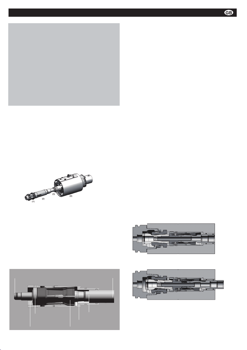
Illustration 1: Complete unit for automatic HSK tension with HSK
clamping set (1), locking unit (2), pull bolt extension (3), clamp and
release unit (4)
The „SuperLock“ locking unit consists of the collet,
draw bolt, clamping sleeve, draw bar and guide
sleeve (illustration 2). It is delivered as a complete
module which is fully assembled. The inserted pull
bolt is removed for installation (compare installation
and assembly). The remaining parts of the SuperLock
module may not be independently dismantled and
assembled.
Connection for HSK clamping set Connection for operating rod
Pull bolt
Connection rod
Clamping sleeve Collet
Illustration 2: conguration of the “SuperLock” locking unit
Guide sleeve
Illustration 3: release position of a locking unit with HSK
clamping set
Illustration 4: clamping position of the locking unit with HSK
clamping set
9
Page 4

1.2 Locking unit functional data
******************************************************************************************* Page: 5
“SuperLock” Locking Unit
Date: 30th April 2009
RN-1701
**********************************************************************************************************
HSK-A/E 25 HSK-A/E 32 HSK-A/E 40 HSK-A/E 50
Draw-in force (HSK clamping force)
3,500 N 5,000 N 10,000 N 15,000 N
Release force (HSK shaft)
ca. 700 N ca. 1,000 N ca. 2,000 N ca. 3,000 N
Nominal clamping stroke (on HSK
clamping set)
4.0 mm 5.5 7.0 mm 8.0 mm
Clamping range (on HSK clamping
set)
3.0-5.0 mm 4.5-6.5 mm 5.5-8.5 6.5-9.5
Ejection stroke
0.2 mm 0.4 mm 0.5 mm 0.5 mm
Operating force on draw bolt
700 N 1,000 N 2,000 N 3,000 N
Nominal clamping stroke on draw bolt
10.8 mm 13.6 mm 17.8 mm 19.9 mm
Stroke range on draw bolt
8.8-12.8 mm 11.6-15.6 mm 14.8-20.8 mm 16.9-22.9 mm
Draw bolt stroke without tool
max. 15.6 mm max. 18.9 mm max. 22.8 mm max. 26.3 mm
HSK-A/E 63 HSK-A/E 80 HSK-A/E 100 HSK-A/E 125
Draw-in force (HSK clamping force)
25,000 N 37,500 N 50,000 N 70,000 N
Release force (HSK shaft)
ca. 5,000 N ca. 7,500 N ca. 10,000 N ca. 14,000 N
Nominal clamping stroke (on HSK
clamping set)
8.0 mm 11.0 mm 12.0 mm 14.0 mm
Clamping range (on HSK clamping
set)
6.0-10.0 9.0-13.0 mm 10.0-14.0 mm 11.5-16.5 mm
Exhaust stroke
0.5 mm 0.5 mm 0.8 mm 0.8 mm
Operating force on pull bolt
5,000 N 7,500 N 10,000 N 15,000 N
Nominal clamping stroke on pull bolt
20.0 mm 27.3 mm 30.8 mm 37.6 mm
Stroke range on pull bolt
16.0-24.0 mm 23.3-31.3 mm 26.8-34.8 mm 32.6-42.6 mm
Pull bolt stroke without tool
max. 28.0 mm max. 38.1 mm max. 42.4 mm max. 50.8 mm
Handspannfutter (Keilstangenprinzip)
Fremdsprachentexte ...
Fremdsprachentexte ...
mit Backensicherung
The locking unit may only be applied in connection with
a Röhm HSK clamping set. Any other applications will
be subjected to a technical test by Röhm.
The locking unit is used to save and maintain the
traction in cooperation with an HSK clamping set. Table
1 contains the forces and strokes for the HSK clamping
set and for the actual locking unit. The forces and
strokes of the HSK clamping set can be determined on
a shaft or socket from the front. The forces on the draw
bolt are initialised with a clamping and release unit. The
draw bolt stroke is measured on a draw bolt extension
on the shaft end.
Overview of forces and strokes of the locking unit
Table 1
The stipulated operating forces on the pull bolt in the
above table are to be achieved to comply with the
draw-in force on the HSK shaft. The application of the
locking unit with lower or higher operating forces on the
pull bolt may not take place independently and must be
coordinated with Röhm in writing.
10
The locking unit works with a wide tolerance or stroke
range (table 1). This allows the safe locking of the
system with HSK tools which exceed or do not achieve
the stipulated tolerances of the clamping shoulder.
Page 5

2. General information on dangers:
Handspannfutter (Keilstangenprinzip)
Fremdsprachentexte ...
Fremdsprachentexte ...
mit Backensicherung
Handspannfutter (Keilstangenprinzip)
Fremdsprachentexte ...
Fremdsprachentexte ...
mit Backensicherung
2.1 Environmental conditions, environmental dangers
Environmental conditions (following DIN EN 60204):
Relative air humidity (at 40°C) 50 %.
•
Environmental pollution within the scope of the pollution
•
resulting from the machine.
Surrounding temperature in the area of use: 5°C to 40°C.
•
Surrounding temperature for transportation and storage:
•
- 15°C to 55°C (up to 70°C for 24 hours).
Environmental dangers
If the locking unit is used as a system component of a
•
complete tool clamping system, particular attention is to
be paid to careful handling of the mediums for lubrication
and cooling (hydraulic oil, lubrication oil/fat or refrigerant
lubricant).
The operating manual RN-1600 contains, in particular, sa-
•
fety information and guidelines for the use of tool holders
which must be carefully read and observed.
2.2 Intended use
The locking unit is constructed and produced according
•
to state of the art. All the relevant safety regulations have
been observed. However, some risks still exist with the
use of the locking unit for the intended purpose.
The locking unit is primarily constructed for the generation
•
and maintenance of traction for HSK clamping sets.
This locking unit is used for the automatic clamping of
•
HSK tools. Due to the type of construction, this clamping
equipment is only suitable for use together with HSK
clamping sets from Röhm. If any other form of use other
than the intended one is considered, written agreement
must be received from the manufacturer.
This locking unit can be used in both vertical and horizon-
•
tal positions for cutting and non-cutting shaping in rapidly
rotating tooling machine spindles.
Use in stationary units without the rotation of the locking
•
unit is possible without any restrictions.
The limit values provided in the technical data (e.g. maxi-
•
mum operating force or maximum clamping stroke) may
not be exceeded. Use with lower operating forces is only
permitted after contacting the manufacturer and receiving
written authorisation.
The locking unit is operated using a clamping and release
unit. The values provided in table 1 for forces and strokes
must be achieved with the clamping and release unit. Supervision of the clamping position of the locking unit during
processing is necessary from a safety point of view.
2.3 Unintended use/obvious misuse
The shape and weight of the clamped HSK tool are very important for the vibration behaviour of the whole tool-clamping
unit-spindle system. This is why:
Tools must have a balanced weight.
•
Tools which are unbalanced must be driven with a lower
•
speed.
The speed limits are determined in accordance with DIN
•
ISO 1940-1 and DIN 69888:2008-09(D).
The connection parts and modules (draw bolt extension,
•
clamping and release unit) which are manufactured by the
customer must be designed and used according to the
details provided in the user documentation and the valid
guidelines.
Changes to the locking unit are generally connected with the
safety risks. This is why:
Changes are not allowed to be undertaken on the locking
•
unit.
Modications of connection parts may only be undertaken
•
after contacting the manufacturer and receiving written
authorisation.
Röhm clamping and release units monitor the clamping
•
position of the locking unit during use (spindle rotation).
If clamping and release units from other manufacturers
are used, Röhm does not accept any responsibility for
faults which occur faults in the locking system and the
consequences of these.
For each clamping and release unit, the use of sensors to
•
determine the release position, the clamping position and
the position for “clamping without a tool” is stipulated. Particular attention is to be paid to monitoring the clamping
position during rotation. The sensors must be connected
with the control of the machine so that changes during
use can be recorded and so that the spindle- stop can be
activated if the limits are exceeded. The stroke range for
the draw bolt provided in table 1 contains the upper and
lower limits for the clamping position and may only partly
be exceeded and may not be fallen short of (refer to 3.2).
The machine spindle may only be started when the
•
clamping position on the stroke control is achieved. The
clamping position must be retrieved with a safety sensor
in accordance with DIN VDE 0660 part 209.
Other safety-related requirements for the operation of
•
tool clamping are shown in RN-1600 and must always be
observed.
2.4 Operator’s duties
The stipulated technical data on the locking unit may not
be exceeded or not achieved unless other information is
expressly given.
Before starting any work on the locking unit, it is necessary
to ensure that:
The relevant parts of the user documentation have been
•
provided to the members of staff responsible for the work.
The user documentation has been read and understood
•
by the responsible members of staff. This particularly
applies to all safety and warning information.
In addition to this operating manual RN-1701, the RN-
•
1600 operating manual and particularly chapter 3 “safety
information and guidelines for the use of tool holders” are
read and observed.
Responsible members of staff are sufciently qualied
•
for the task. This particularly applies to initialisation,
maintenance/servicing and repairs and for all work on
electrical equipment and components. The relevant
regulations and guidelines and the user documentation
must be observed.
All safety devices have been used correctly and are fully
•
functional. Safety devices may not be manipulated or taken out of use. The resistance classes of the separating
protection devices (e.g. protection covers or safety glass)
must be observed.
The machine and the locking unit are be in perfect tech-
•
nical condition.
All damaged or defective parts are be replaced immedia-
•
tely. This particularly applies to all safety devices.
11
Page 6

3. Assembly, initialisation and dismantling
Handspannfutter (Keilstangenprinzip)
Fremdsprachentexte ...
Fremdsprachentexte ...
mit Backensicherung
3.1 Assembly
3.1.1. Order of assembly
3.1.1.1 Draw bolt
In order to install the “SuperLock” locking unit, the rst
step is to “pull out” the draw bolt from the complete module which has been supplied fully mounted. The draw
bolt must then be installed in the spindle (receiver). It is
preferable to screw the draw bolt outside of the spindle
with the draw bolt extension (with an Allen wrench on
the head of the draw bolt - refer to table 2 below for key
width). The mounting of the draw bolt can also be carried
out from the front with a standard sleeve socket wrench
and extension. The respective torque for the draw bolt is
also contained in table 2.
The draw bolt extension is inserted into the spindle from
the back and secured to the spindle depending upon the
individual construction of the spindle.
3.1.1.2 Clamping/release units and draw bolt
The next step is to mount the clamping and release unit.
In the release position, the position of the head end of
the draw bolt is measured in the spindle (illustration 5,
table 2, dimensions l1). Corrections to the position of the
draw bolt can only be undertaken on the clamping and
release unit or the draw bolt extension.
0 0
SW
l1
3.1.1.3 Locking unit
First of all, the guide sleeve of the locking unit is inserted
in the spindle. Attention should be paid to the careful insertion of the O-ring on the guide sleeve into the spindle
drill hole in order to avoid the shearing of the O-ring.
The module with clamping sleeve, collet and draw bar
is screwed into the spindle from the front. The movable,
protuding collet in the clamping sleeve is initially positioned over the pull bolt without any screwing movement.
The collet is then manually placed on the head of the
draw bolt, the clamping sleeve is repositioned on the
collet as far as it will go on the rotation prevention screw
and is then pushed axial onto the draw bolt (compare
illustration 6) with some pressure. Depending upon
the HSK nominal size, this process is undertaken with
some application of force due to the spread of the collet.
Standard tools can be used as aids.
Assembly position
Illustration 6: position of the collet in the clamping sleeve during
assembly of the draw bolt.
Once the collet has taken position on the draw bolt and
can be freely turned, the clamping sleeve can be screwed in with a mounting wrench. The mounting wrench
required and the torque for the clamping sleeve are
included in table 3.
Draw bolt Spindle
Illustration 5: control dimensions for the installation of the draw bolt
(l1), key width on the draw bolt (SW)
Key width (SW), torque (Mz) and control dimensions
for the draw bolt (l1)
HSK nominal
size:
Key width on
the draw bolt
(SW):
Draw bolt torque Mz (Nm):
Draw bolt-HSK
contact face l1
(mm):
Table 2
12
25 32 40 50 63 80 100 125
6,35 8 10 12 15 19 22 28
5 10 20 40 80 150 250 400
30,4 36,5 47,5 56,2 72 93,1 117,8 145,1
Mounting wrench and torque for mounting the
clamping sleeve
HSK nominal
size:
Röhm ID no
for mounting
wrench
Clamping
sleeve
torque Mh
(Nm)
Table 3
25 32 40 50 63 80 100 125
1172346 1143355 1176112 1176114 1172348 1176116 1176118 1176120
15 25 35 50 70 95 125 160
Page 7

3.1.1.4 HSK clamping set
Handspannfutter (Keilstangenprinzip)
Fremdsprachentexte ...
Fremdsprachentexte ...
mit Backensicherung
Once the clamping sleeve has been successfully
mounted, the HSK clamping set can be installed. The
assembly and setting regulations for HSK clamping sets
must also be observed.
In order to determine the necessary position of the
pressure head in the release position, the calibrating
disc included in the delivery must be cut to the necessary size. In order to do this, the pressure head with
a calibrating disc is screwed to the drae bar and the
resulting is measured.
The thickness of the calibrating disc is then reduced
by the difference between the existing amount and the
stipulated amount. The pressure head underlaid with
the adapted calibrating disc is countered on the draw
bar (compare the setting measurement in the assembly
drawings).
Warning: the tolerance range for the setting
measurement may not be exceeded! During
start-up operations, proceed with particular care
in order not to damage the threaded pins of the
rotation prevention on the collet. The position of
the draw bolt described in point 3.1.1.2 must also
be observed.
Once the HSK clamping set is mounted, the full system
with the locking unit and clamping and release unit is
now ready for use.
stroke on the draw bolt). Table 1 contains these values for
all HSK sizes (stroke range on the draw bolt: e.g. 16-24
mm for HSK63).
Analogue sensors are generally used to establish the
stroke range. The sensor must be coupled with the machine controls in such a way that the necessary “clamping
window” for the “clamping tool” function is identied and so
that the spindle shuts down if changes to the axial clamping position take place during rotation.
3.2.3 „Clamping without tool“ position
The maximum value of the clamping position can be
exceeded as long as it is ensured that the clearance to the
“clamping without tool” position does not lead to malfunctions. Depending upon the nominal size, it is recommended that a minimum clearance of 1-2 mm is maintained
between “clamping” and “clamping without tool”. This also
applies to special applications. Table 1 contains the maximum values of strokes for clamping without a tool.
3.2.4 Sensor technology for determining the position
In order to establish the positions described above, suitable sensor technology which is linked with the machine
controls must be used. If these modules, as a part of the
clamping and release units, are not purchased from Röhm,
the monitoring functions described above must be imple-
mented in a sufcient manner.
3.1.2 Mounting aids
The locking unit can be installed with standard mounting
tools. Special keys are only required for mounting the
clamping sleeve. Standard torque keys can be used
on the special keys (refer to table 3 for Röhm ID no) to
apply the right torque level.
3.2 Initialisation
The functions of the locking unit can be checked by
operating the clamping and release unit when the
spindle is stationary. The “tool released“, “tool clamped” and “clamped without tool” positions are determined (refer to table 1 for values). An HSK testing tool with
“0 position” on the HSK clamping shoulder is used to
determine the exact clamping position.
In order to determine the positions of the various operating positions, the relevant sensors must be tuned to the
clamp strokes and signal ranges in the machine control
must be recorded.
3.2.1 “Tool released” position
This position is checked when mounting the full system
(refer to 3.1).
3.2.2 „Tool clamped“ position
Due to the tolerances of the HSK tools, the tolerances
of further elements in the force ow and the at angle in
the locking unit results in a relatively wide clamping range around the ideal clamping point (nominal clamping
The monitoring of the clamping position of the
locking unit during processing is necessary from
a safety point of view. If the operator of the locking
unit does not monitor the clamping position, Röhm
expressly refuses any liability for possible damages caused by malfunction of the locking unit.
13
Page 8

3.2.5 Measuring the clamping force
Handspannfutter (Keilstangenprinzip)
Fremdsprachentexte ...
Fremdsprachentexte ...
mit Backensicherung
The existing clamping force is measured with the help
of HSK clamping force measuring equipment by inserting it in the spindle. The HSK clamping forces (draw-in
forces) result from the respective operating forces on
the draw bolt (table 1).
3.3 Dismantling
The locking unit is dismantled in the release position in
the following order:
The HSK clamping set is dismantled
•
The clamping sleeve is released with a special key
•
(refer to table 3 for Röhm ID no)
The clamping sleeve is removed together with collet
•
and draw bar
The draw bolt is screwed from the draw bolt extensi-
•
on (sleeve socket wrench)
Dismantling can only take place from the front side of
the spindle. The clamping and release unit must not be
dismantled. A requirement for dismantling the draw bolt
is the rotation prevention of the draw bolt extension.
lity. In order to check the condition of the unit, it must be
tested at regular intervals according to the maintenance
instructions. Irrespective of the clamping frequency, a
clamping force test must be carried out after approximately 40 operating hours. Special clamping force devices
(draw-in force measuring equipment) should be used if
necessary.
The HSK clamping set should be lubricated if the clam-
ping force signicantly deviates from the target value
(refer to the clamping set instruction manual). If these
measures are not successful, the HSK clamping set must
be replaced. The clamping force measurements can also
be supported by stroke measurements.
The locking unit must only be replaced according to the
procedure in 3.3 if the new HSK clamping set does not
lead to optimal results and if exceptional loss of the clamping force occurs.
6. Replacement parts
Defective or worn individual parts are not renewed. In
such cases, the locking unit is fully exchanged.
In order to be able to smoothly process subsequent
orders for replacement parts, it is necessary to state
the 7 digit identication number engraved on the
module and, if available, the fabrication number.
4. Operation
Release the function positions; clamping and clamping without a tool can be achieved with different
clamping and release units. Irrespective of the
construction and the type of generated forces (hydraulic, pneumatic or electric), the operating elements
must always be brought into the neutral position
before starting the spindle. The respective pistons etc
may not come into contact with the end of the draw
bolt and must maintain a constant safety clearance
during the rotation of spindle.
Once the clamping force has been introduced, the locking unit transfers the operating force onto the HSK
clamping set and mechanically self-locks this traction.
The operating force must and may not be applied
during rotation of the spindle.
The monitoring of the various function positions during standstill and the clamping position during rotation
can be individually triggered with different types of
sensors whereby the specic information in chapter 2
must be observed.
5. Maintenance and servicing
The locking unit is maintenance-free. Lubrication
cycles or the replacement of expendable parts is not
necessary.
Clamping force measurements are recommended
to control functions. After a free stroke (clamping
without tool), HSK clamping force measurements can
be undertaken with standard equipment.
The condition of the locking unit is decisive for its
function, clamping and locking force and its durabi-
14
We draw your attention to the fact that exclusively ORIGINAL Röhm parts or parts from authorised Röhm GmbH
suppliers must be used. No liability is accepted by Röhm
GmbH for any damages resulting from the use of parts
from other companies.
Furthermore, the warranty does not include:
Damages caused by the operator due to failure to full
1.
the written instructions of the seller with reference to
the operation and maintenance of the equipment.
Natural wear and tear.
2.
Damages caused by force majeure.
3.
Damages caused by any type of incorrect operation or
4.
caused by improper use or operation of the clamping
facility or parts thereof.
Damages caused by third parties.
5.
Damages which are caused by the use of the system
6.
or parts thereof under irregular conditions (e.g. materials, work pieces, tools, cutting data or programs etc),
particularly without consulting the seller or manufacturer and receiving written approval.
Damages which can be traced back to changes to
7.
environmental conditions.
Page 9

Comentario previo:
Handspannfutter (Keilstangenprinzip)
Fremdsprachentexte ...
Fremdsprachentexte ...
mit Backensicherung
E
F
El presente manual de instrucciones ha sido realiz-
1.
ado considerando las normas DIN EN ISO 12100-1,
DIN EN ISO 12100-2 y las correspondientes norma
tivas pertinentes.
En caso de diferentes tensiones de la herramienta,
2.
las fuerzas resp. los momentos necesarios para
la aplicación de las fuerzas de sujeción precisas
se deberán determinar conforme a la directriz VDI
3106 (compare también la directriz VDMA 34181).
Dado el caso, el número de revoluciones admisible
deberá regularse.
El presente manual de instrucciones es válido
3.
para todos los tamaños nominales del sistema de
enclavamiento. Podrá pedir los dibujos de montaje
y las listas de piezas para los respectivos tamaños
nominales a la empresa RÖHM.
1. Descripción
1.1 Estructura y características de funcionamiento
El sistema de enclavamiento „SuperLock“ es un componente de un sistema de amarre automático HSK. Sirve
para la trasmisión de la fuerza de tracción al grupo
tensor HSK y el posterior enclavamiento de retención
automática y conservación de la fuerza tensora. El
modelo estándar del sistema de enclavamiento dispone
de una prolongación del perno de tracción en la que
una unidad tensora y de aojamiento trasmite la fuerza
tensora y de aojamiento resp. las carreras tensoras y
de aojamiento (imagen 1).
Imagen 1: Sistema completo para la amarre HSK automático con
grupo tensor HSK (1), sistema de enclavamiento (2), prolongación
del perno de tracción (3), unidad tensora y de aojamiento (4)
El sistema de enclavamiento „SuperLock“ está
compuesto por los elementos mandril de pinza, perno
de tracción, manguito de montaje, barra de tracción
y manguito guía (imagen 2). Se envía en forma de
componente completo y en estado montado. Para
el montaje se extrae el perno de tracción encajado
(véase instalación y montaje). Las otras piezas del
componente SuperLock no se deben desmontar y
montar de manera autónoma.
Conexión para HSK
grupo tensor
Conexión para la barra del
funcionamiento
Tras el montaje del sistema de enclavamiento, se
•
atornilla la pieza de presión del grupo tensor HSK a
la barra de tracción del sistema de enclavamiento. El
perno de tracción del sistema de enclavamiento se
une durante el montaje del sistema, mediante una
prolongación de perno de tracción original de Röhm
o una barra de accionamiento diseñada según las
necesidades del cliente, al extremo del husillo.
Por lo general, la barra de tracción del sistema de
•
enclavamiento dispone de un taladro pasante centrado y estanqueizado para la alimentación interna.
La utilización de este taladro para el tamaño HSK25
sólo es posible con una pieza de presión adaptada
del grupo tensor HSK25. Los grupos tensores de los
otros tamaños nominales de HSK (HSK32-HSK125)
disponen de taladros pasantes para la alimentación y
pueden ser combinados con el sistema de enclavamiento „SuperLock“ sin necesidad de medidas
adicionales.
En la posición de aojamiento (imagen 3), el perno
•
de tracción está en posición avanzada sobre la barra
de tracción y la pieza de presión en la posición de
expulsar para soltar la herramienta HSK.
La posición de tensión (imagen 4) se alcanza median-
•
te la introducción de fuerza en el perno de tracción
(prolongación del perno de tracción), mientras que
entre el cono exterior del perno de tracción y el cono
interior del mandril de pinza se genera el enclavamiento con retención automática. Tras haber alcanzado la posición tensora, el elemento de introducción
de fuerza (p. ej. un pistón hidráulico) de la unidad
tensora y de aojamiento retoma la posición neutral,
en la que la prolongación de perno de tracción puede
rotar libremente.
La unidad tensora y de aojamiento se debe con-
•
gurar de tal manera que se alcancen las carreras y
fuerzas tensoras prescritas. Se deberá atender, sobre
todo, el posible margen de carrera tensora generado
por la tolerancia de las herramientas HSK (véase
también Montaje/desmontaje).
Imagen 3: Posición de aojamiento del sistema de enclavamiento
con grupo tensor HSK
barra de la conexión
brida de sujeción Collar
Imagen 2: Estructura del sistema de enclavamiento „SuperLock“
tire del perno
manga de la guía
Imagen 4: Posición de tensión del sistema de enclavamiento
con grupo tensor HSK
21
Page 10

1.2 Datos de funcionamiento del sistema enclavamiento
******************************************************************************************* Página: 5
Sistema de enclavamiento "SuperLock"
Fecha: 30 de abril de 2009
RN-1701
**********************************************************************************************************
tracción se introducen desde atrás mediante una unidad tensora y de aflojamiento. La carrera del
perno de tracción se mide en el extremo del husillo en una prolongación del perno de tracción.
HSK-A/E 25 HSK-A/E 32 HSK-A/E 40 HSK-A/E 50
Fuerza de amarre (fuerza de amarre
HSK)
3.500 N 5.000 N 10.000 N 15.000 N
Fuerza de aflojamiento (mango HSK)
aprox. 700 N aprox. 1.000 N aprox. 2.000 N aprox. 3.000 N
Carrera tensora nominal (en el grupo
tensor HSK)
4,0 mm 5,5 7, 0 mm 8,0 mm
Zona tensora nominal (en el grupo
tensor HSK)
3,0-5,0 mm 4,5-6,5 mm 5,5-8,5 6,5-9,5
Carrera de expulisión
0,2 mm 0,4 mm 0,5 mm 0,5 mm
Fuerza de accionamiento en el perno
de tracción
700 N 1.000 N 2.000 N 3.000 N
Carrera tensora nominal en el perno
de tracción
10,8 mm 13,6 mm 17,8 mm 19,9 mm
Carreras en el perno de tracción
8,8-12,8 mm 11,6-15,6 mm 14,8-20,8 mm 16,9-22,9 mm
Carrera del perno de tracción sin
herramienta
máx. 15,6 mm máx. 18,9 mm máx. 22,8 mm máx. 26,3 mm
HSK-A/E 63 HSK-A/E 80 HSK-A/E 100 HSK-A/E 125
Fuerza de amarre (fuerza de amarre
HSK)
25.000 N 37.500 N 50.000 N 70.000 N
Fuerza de aflojamiento (mango HSK)
aprox. 5.000 N aprox. 7.500 N aprox. 10.000 N aprox. 14.000 N
Carrera tensora nominal (en el grupo
tensor HSK)
8,0 mm 11,0 mm 12,0 mm 14,0 mm
Zona tensora nominal (en el grupo
tensor HSK)
6,0-10,0 9,0-13,0 mm 10,0-14,0 mm 11,5-16,5 mm
Carrera de expulisión
0,5 mm 0,5 mm 0,8 mm 0,8 mm
Fuerza de accionamiento en el perno
de tracción
5.000 N 7.500 N 10.000 N 15.000 N
Carrera tensora nominal en el perno
de tracción
20,0 mm 27,3 mm 30,8 mm 37,6 mm
Carreras en el perno de tracción
16,0-24,0 mm 23,3-31,3 mm 26,8-34,8 mm 32,6-42,6 mm
Carrera del perno de tracción sin
herramienta
máx. 28,0 mm máx. 38,1 mm máx. 42,4 mm máx. 50,8 mm
Handspannfutter (Keilstangenprinzip)
Fremdsprachentexte ...
Fremdsprachentexte ...
mit Backensicherung
E
F
El sistema de enclavamiento sólo se puede emplear en
combinación con un grupo tensor HSK de Röhm. Otros
empleos serán sometidos a un control técnico por parte
de Röhm.
El sistema de enclavamiento se emplea para el almacenamiento y la conservación de una fuerza de tracción
en interacción con un grupo tensor HSK. La tabla 1 mu-
Vista general de las fuerzas y carreras del sistema de enclavamiento
estra las fuerzas y carreras para el grupo tensor HSK
y para el sistema de enclavamiento en sí. Las fuerzas
y carreras del grupo tensor HSK se pueden determinar
por delante en un husillo o un alojamiento. Las fuerzas
en el perno de tracción se introducen desde atrás medi-
ante una unidad tensora y de aojamiento. La carrera
del perno de tracción se mide en el extremo del husillo
en una prolongación del perno de tracción.
Tabla 1
Para el cumplimiento de la fuerza de amarre en el
mango HSK se deben realizar, en el perno de tracción,
las fuerzas de accionamiento nombradas en la tabla
de arriba. El empleo del sistema de enclavamiento
con fuerzas de accionamiento inferiores o superiores
no se debe realizar por cuenta propia, sino deberá ser
22
acordado por escrito con Röhm.
El sistema de enclavamiento trabaja con una amplia
gama de tolerancia resp. carreras (Tabla 1), gracias
a ello se puede realizar un enclavamiento seguro del
sistema con herramientas HSK que sobrepasen o no
alcancen las tolerancias jadas del hombro.
Page 11

2. Indicaciones de peligro generales
Handspannfutter (Keilstangenprinzip)
Fremdsprachentexte ...
Fremdsprachentexte ...
mit Backensicherung
E
F
2.1 Condiciones ambientales, peligros ambientales
Condiciones ambientales (siguiendo la DIN EN 60204):
humedad atmosférica relativa (a 40º C) 50%
•
Ensuciamiento del entrono en el margen del ensuciamiento
•
generado por las máquinas mismas.
Temperatura ambiente en el lugar de empleo de 5º C hasta 40º C.
•
Temperatura ambiente durante el transporte y almacenamiento de
•
-15º C hasta 55º C (durante 24 h también hasta 70º C).
Peligros ambientales
si se emplea el sistema de enclavamiento como componente
•
de un sistema de amarre de herramienta completo, se deberá
prestar especial atención al manejo cuidadoso de los medios
de lubricación y refrigeración (aceite hidráulico, aceite/grasa
lubricante, medios de refrigeración).
en lo concerniente, el manual de instrucciones RN-1600
•
contiene indicaciones de seguridad y directrices para el empleo
de tensores de herramienta que deberán ser leídas con detenimiento y seguidas.
2.2 Uso previsto
El sistema de enclavamiento ha sido construido y fabricado
•
según el estado de la técnica. Se han tenido en cuenta todas
las normas de seguridad pertinentes. No obstante, aún durante
el uso previsto del sistema de enclavamiento existen peligros
remanentes.
El sistema de enclavamiento ha sido particularmente construi-
•
do para la generación y conservación de la fuerza de tracción
para grupos tensores HSK.
El sistema de enclavamiento se emplea para el amarre
•
automático de herramientas HSK. A causa de su forma de
construcción, este dispositivo de amarre sólo se puede utilizar
en interacción con grupos tensores HSK de la empresa Röhm.
Si se considera un empleo distinto al previsto, se requiere el
permiso escrito del fabricante.
El presente sistema de enclavamiento se puede emplear para
•
la conformación con o sin arranque de virutas en husillos de
máquinas-herramienta de rotación rápida, tanto en posición
horizontal como, también, vertical.
El sistema de enclavamiento, también, se puede emplear sin
•
restricciones en unidades sin rotación.
No se deben exceder los valores límite expuestos en los
•
datos técnicos (p.ej. fuerza máxima de accionamiento, carrera
máxima tensora). El empleo con fuerzas de accionamiento inferiores sólo está permitido tras coordinación y permiso escrito
por parte del fabricante.
El sistema de enclavamiento se acciona a través de una
•
unidad tensora y de aojamiento. Con la unidad tensora y de
aojamiento incorporada se tienen que alcanzar los valores
de fuerzas y carreras expuestos en la tabla 1. Desde el punto
de vista de la seguridad, es necesario controlar la posición de
tensión del sistema de enclavamiento durante el trabajo.
2.3 Empleo inadecuado / evidente uso indebido
La forma y masa de la herramienta HSK tensada es de gran
importancia para el comportamiento de oscilación del completo
sistema-herramienta-unidad tensora-husillo. Por eso:
Las herramientas deben disponer de una masa equilibrada.
•
En caso de herramientas desequilibradas se deberá trabajar
•
con un número reducido de revoluciones.
El límite del número de revoluciones resulta de las normativas
•
DIN ISO 1940-1 y DIN 69888:2008-09(D).
Las piezas de empalme y los componentes fabricados por
•
el cliente mismo (prolongación del perno de tracción, unidad
tensora y de aojamiento) deberán proyectarse y emplearse
según las indicaciones incluidas en la documentación del
usuario y las directrices vigentes.
Siempre existe un riesgo de seguridad si se realizan modicaciones en el sistema de enclavamiento. Por eso:
No está permitido realizar modicaciones en el sistema de
•
enclavamiento.
Las modicaciones en las piezas de empalme sólo se deben
•
realizar en coordinación y tras haber recibido el permiso
escrito por parte del fabricante.
Las unidades tensoras y de aojamiento de Röhm controlan
•
la posición de tensión del sistema de enclavamiento durante
el uso (rotación de husillo). Si se emplean unidades tensoras
y de aojamiento de otros fabricantes, Röhm no asumirá
ninguna responsabilidad por posibles fallos del sistema de
enclavamiento y sus consecuencias resultantes.
Para cada unidad tensora y de aojamiento es obligatorio em-
•
plear sensores para la detección de la posición de aojamiento y tensión, así como la posición „Tensar sin herramienta“.
La posición de tensión durante la rotación deberá controlarse
con especial esmero. Los sensores deberán acoplarse de tal
manera al sistema de mando de la máquina que se puedan
detectar los cambios durante el uso y, en caso de exceder los
límites, se active la parada del husillo. Las carreras del perno
de tracción expuestas en la tabla 1 incluyen el límite superior
e inferior de la posición de tensión y sólo deberán ser sobrepasadas bajo determinadas condiciones y nunca se deberá
generar un nivel inferior (véase 3.2).
El husillo de la máquina no se deberá poner en funcionamien-
•
to hasta que no se haya alcanzado la posición de tensión
en el control de carrera. La posición de tensión se tiene que
comprobar con un sensor de seguridad según DIN VDE 0660
parte 209.
Encontrará los requisitos de seguridad adicionales para el
•
manejo de amarres de herramienta en el manual RN-1600, es
imprescindible seguirlos.
2.4 Obligaciones del operador
Si no ha sido expuesto explícitamente de otra manera, los datos
técnicos expuestos del sistema de enclavamiento no deberán ser
sobrepasados o no alcanzados.
Antes de comenzar a trabajar con el sistema de enclavamiento
deberá cerciorarse
de que el personal pueda acceder a las respectivas partes de
•
la documentación del usuario.
la documentación del usuario haya sido leída y entendida por
•
el personal competente. Sobre todo en lo respectivo a las
indicaciones de seguridad y advertencia.
que, además, del presente manual de instrucciones RN-1701
•
se haya leído y se tenga en cuenta el manual de instrucciones
RN-1600, sobre todo el capítulo 3 „indicaciones de seguridad
y directrices para el empleo de tensores de herramienta“.
de que el personal responsable disponga de la calicaci-
•
ón adecuada para su trabajo. Sobre todo si se trata de la
puesta en servicio, el mantenimiento/la conservación y los
arreglos, así como todos los trabajos en las instalaciones y los
componentes eléctricos. Deberán tenerse en cuenta todas las
prescripciones y directrices pertinentes y la documentación
del usuario.
de que todos los dispositivos de seguridad se hayan colocado
•
debidamente y sean capaces de funcionar. Los dispositivos de
seguridad no deberán ser manipulados ni encontrarse fuera
de servicio. Deberá tener en cuenta las clases de resistencia
de los dispositivos de protección (p.ej. cubiertas de protección,
ventanas de seguridad).
de que la máquina y el sistema de enclavamiento se encuen-
•
tren en un estado técnico intacto.
de que todas las piezas dañadas o defectuosas se renueven
•
inmediatamente. Sobre todo si se trata de los dispositivos de
seguridad.
23
Page 12

3. Montaje, puesta en servicio, desmontaje
Handspannfutter (Keilstangenprinzip)
Fremdsprachentexte ...
Fremdsprachentexte ...
mit Backensicherung
E
F
3.1 Montaje
3.1.1. Orden de montaje
3.1.1.1 Perno de tracción
Para el montaje del sistema de enclavamiento
„SuperLock“ se „retira“ primero el perno de tracción
del componente que ha sido suministrado de forma
montado. A continuación, se realiza el montaje del perno
de tracción en un husillo (alojamiento). Se atornilla el
perno de tracción, preferentemente fuera del husillo, a
la prolongación del perno de tracción (hexágono exterior
en la cabeza del perno de tracción, ancho de llave
véase tabla 2 abajo). El montaje del perno de tracción
también se puede realizar desde delante con una llave
de vaso corriente y una prolongación. Los momentos de
apriete correspondientes para el perno de tracción están
incluidos en la tabla 2.
La prolongación del perno de tracción se introduce en el
husillo desde atrás y se ja al extremo del husillo según
la construcción individual de cada husillo.
3.1.1.2 Unidad tensora y de aojamiento, perno de
tracción
A continuación se realiza el montaje de la unidad
tensora y de aojamiento. En la posición de aojamiento
se mide la posición de la supercie frontal del perno de
tracción en el husillo (imagen 5, tabla 2, medida l1). Las
correcciones de la posición del perno de tracción sólo se
pueden realizar en la unidad tensora y de aojamiento o
en la prolongación del perno de tracción.
0 0
SW
l1
3.1.1.3 Sistema de enclavamiento
Primero se introduce el manguito guía del sistema de
enclavamiento en el husillo. Se tiene que tener cuidado
al introducir la junta tórica del manguito guía en el
taladro del husillo para evitar cortes en ella.
El componente con el manguito de montaje, el mandril
de pinza y la barra de tracción se atornilla desde delante
en el husillo. Primero se desliza el mandril de pinza,
que se puede desplazar en el manguito de montaje y
sobresale, sin movimiento de atornillado sobre el perno
de tracción.
Para ello se posiciona el mandril de pinza manualmente
sobre la cabeza del perno de tracción, el manguito de
montaje se pospone en relación al mandril de pinza
a tope con el tornillo de protección contra torsión y
nalmente se empuja con una fuerte presión axialmente
sobre el perno de tracción (compare imagen 6). Este
proceso se realiza, según el tamaño nominal HSK, con
un ligero esfuerzo a causa de la apertura del mandril
de pinza. Puede emplear herramientas corrientes como
ayuda.
Posición de montaje
Imagen 6: Posición del mandril de pinza en el manguito de montaje
durante el montaje en el perno de tracción
En cuanto el mandril de pinza haya alcanzado su posición sobre el husillo de tracción y se pueda girar libremente, se puede atornillar el manguito de montaje con
una llave de montaje. Las llaves de montaje necesarias
y los momentos de apriete para el manguito de montaje
Perno de tracción Ilave
Imagen 5: Medida de control para el montaje del perno de tracción
(l1), ancho de llave en el perno de tracción (SW)
Ancho de llave (SW), momento de apriete (Mz) y
medida de control para el perno de tracción (l1)
Tamaño nominal HSK:
Ancho de llave
en el perno de
tracción (SW):
Momento de
apriete perno
de tracción Mz
(Nm):
Perno de
tracción HSKdisposición
proyectada l1
(mm):
Tabla 2
24
25 32 40 50 63 80 100 125
6,35 8 10 12 15 19 22 28
5 10 20 40 80 150 250 400
30,4 36,5 47,5 56,2 72 93,1 117,8 145,1
Llaves de montaje y momentos de apriete para el
montaje del manguito de montaje
Tamaño
nominal
HSK:
Nº de id
Röhm llave
de montaje
Momento
de apriete
manguito de
montaje Mh
(Nm)
Tabla 3
25 32 40 50 63 80 100 125
1172346 1143355 1176112 1176114 1172348 1176116 1176118 1176120
15 25 35 50 70 95 125 160
Page 13

3.1.1.4 Grupo tensor HSK
Handspannfutter (Keilstangenprinzip)
Fremdsprachentexte ...
Fremdsprachentexte ...
mit Backensicherung
E
F
Después del montaje del manguito de montaje se
puede montar el grupo tensor HSK. Para ello tendrá
que atenerse, también, a las prescripciones de montaje
y ajuste para grupos tensores HSK.
Para la adaptación de la posición necesaria de la pieza
de presión en posición de aojamiento, se deberá lijar
la arandela de adaptación suministrada a la medida
necesaria. Para ello se atornilla la pieza de presión con
la arandela de adaptación a la barra de tracción y se
mide la medición de ajuste resultante.
El grosor de la arandela de adaptación se reduce
en la medida de diferencia entre la medida de ajuste
existente y la medida de ajuste prescrita. Entonces se
ja la pieza de presión con la arandela de adaptación corregida debajo con contratuerca en la barra de
tracción (compare medida de ajuste en los dibujos de
montaje.)
Atención: ¡la medida de ajuste no debe rebasar
el margen de tolerancia! En modo de entrada se
deberá actuar con sumo cuidado para no dañar
los pasadores roscados para la protección contra
torsión del mandril de pinza. También se deberá
tener en cuenta la posición del perno de tracción
expuesta bajo 3.1.1.2.
Con el montaje del grupo tensor HSK, está listo el sistema completo con sistema de enclavamiento y unidad
tensora y de aojamiento.
3.1.2 Recursos auxiliares para el montaje
El sistema de enclavamiento se puede montar con
ayuda de herramientas de montaje convencionales.
Sólo se emplean llaves especiales para el montaje del
manguito de montaje. Sobre las llaves especiales (nº de
id. Röhm véase tabla 3) se pueden poner, para realizar
el momento de apriete denido, llaves dinamométricas
convencionales.
3.2 Puesta en servicio
Accionando la unidad tensora y de aojamiento, con
husillo parado se pueden controlar las funciones del
sistema de enclavamiento. Se determinan las posi-
ciones „herramienta aojada“, „herramienta tensada“ y
„tensada sin herramienta“ (valores véase tabla 1). Para
la determinación exacta de la posición de tensión se
emplea una herramienta control HSK con „posición 0“
del hombro HSK.
A causa de las tolerancias de las herramientas HSK, las
tolerancias de elementos adicionales en el ujo de fuerza
y los ángulos en el sistema de enclavamiento, se genera
una zona de tensión relativamente amplia alrededor del
punto de tensión ideal (carrera tensora nominal en el perno
de tracción). La tabla 1 contiene estos valores para todos
los tamaños HSK (carreras en el perno de tracción: p. ej.
16-24 mm para HSK63).
Por lo general, se emplean sensores análogos para la
detección de las carreras. El sensor se deberá acoplar
de tal manera al sistema de mando de la máquina que se
detecte la „ventana de tensión“ necesaria para la función
„tensar herramienta“ y, en caso de cambios de la posición
de tensión axial durante la rotación, se desconecte el
husillo.
3.2.3 Posición „tensar sin herramienta“
Se podrá rebasar el valor máximo de la posición de tensión
siempre que se garantice que la distancia hacia la posición
„tensar sin herramienta“ no genere mal funcionamiento. Se
recomienda, según el tamaño nominal, mantener también
en las aplicaciones especiales una distancia mínima de
1-2 mm entre „tensar“ y „tensar sin herramienta“. La tabla
1 incluye los valores máximos de las carreras para tensar
sin herramienta.
3.2.4 Sensores para la detección de la posición
Para la detección de las posiciones nombradas anteriormente se deben emplear sensores apropiados que deberán ser acoplados al sistema de mando de la máquina.
Si estos dispositivos que forman parte de la unidad tensora
y de aojamiento no los adquiere a través de Röhm, se
deberán realizar las funciones de control descritas con
anterioridad de forma adecuada.
Desde el punto de vista de la seguridad, es
necesario controlar la posición de tensión del
sistema de enclavamiento durante el trabajo. Si el
operador del sistema de enclavamiento no realiza
ningún control de la posición de tensión, Röhm
no asumirá ninguna responsabilidad por posibles
daños a causa de mal funcionamiento del sistema
de enclavamiento.
Para la detección de la posición de las diversas posiciones de conmutación se tendrían que adaptar los
sensores correspondientes a las carreras tensoras y
las zonas de señales se tendrían que almacenar en el
sistema de mando de la máquina.
3.2.1 Posición „herramienta aojada“
Esta posición se comprueba durante el montaje del
sistema completo (véase 3.1).
3.2.2 Posición „herramienta tensada“
25
Page 14

3.2.5 Medición de la fuerza tensora
Handspannfutter (Keilstangenprinzip)
Fremdsprachentexte ...
Fremdsprachentexte ...
mit Backensicherung
E
F
Con la ayuda de un dispositivo de medición de fuerza
tensoras HSK se mide la fuerza tensora existente
mediante introducción en el husillo. Con las correspondientes fuerzas de accionamiento en el perno de
tracción (tabla 1) se generan las fuerzas de tensión
HSK (fuerzas de amarre).
3.3 Desmontaje
El desmontaje del sistema de enclavamiento se realiza
en posición de aojamiento y en orden siguiente:
• Desmontaje del grupo tensor HSK
• Soltar el manguito de montaje con la llave especial
(nº de id. Röhm véase tabla 3)
• Extraer el manguito de montaje unido al mandril de
pinza y la barra de tracción.
• Desatornillar el perno de tracción de la prolongación
del perno de tracción (llave de vaso)
El desmontaje sólo se podrá realizar desde el lado
frontal del husillo. No es necesario desmontar la unidad
tensora y de aojamiento. La condición previa para
el desmontaje del perno de tracción es la protección
contra torsión de la prolongación de perno de tracción.
4. Manejo
Las posiciones de funcionamiento aojar, tensar y
tensar sin herramienta se pueden realizar con una
variedad de unidades tensoras y de aojamiento.
Independientemente del modo de construcción y del
tipo de generación de fuerza (hidráulica, neumática,
eléctrica), todos los elementos de accionamiento
tienen que adoptar una posición de estacionamiento
antes de la puesta en funcionamiento del husillo. Los
correspondientes pistones u otros no deben rozar el
extremo del perno de tracción y deben mantener una
distancia de seguridad constante durante la rotación
del husillo.
Tras la introducción de la fuerza tensora, el sistema
de enclavamiento trasmite la fuerza de accionamiento
al grupo tensor HSK y mantiene la fuerza de tracción
mecánicamente con retención automática. La fuerza
de accionamiento no tiene ni debe aparecer durante
la rotación del husillo.
El control de las diversas posiciones de funcionamiento en estado parado y en posición tensada
durante la rotación se puede realizar de manera
individual con sensores de diversos tipos, no obstante, se deberán tener en cuenta las indicaciones
expuestas en el capítulo 2.
5. Mantenimiento, Cuidado
El sistema de enclavamiento no precisa mantenimiento. No existen ciclos de lubricación y no se
tienen que reponer piezas de desgaste.
Para el control de funcionamiento, se recomienda la
medición de la fuerza tensora. Tras una carrera en
26
vacío (tensar sin herramienta) se puede realizar la medición de la fuerza tensora HSK con los aparatos corrientes.
El estado del sistema de enclavamiento es decisivo para
su fuerza de funcionamiento, tensión y enclavamiento, así
como para su vida útil. Para controlar el estado se deberá
realizar un control en periodos de tiempo regulares y
según las indicaciones de mantenimiento. Independientemente de la frecuencia de tensión, al alcanzar 40 horas
de servicio es obligatorio realizar un control de la fuerza
de tensión. En caso necesario, deberán emplearse dispositivos especiales de medición de la fuerza de tensión
(dispositivos de medición de la fuerza de amarre).
Si se detectan desviaciones extremas de la fuerza de
tensión del valor nominal, se deberá lubricar primero el
grupo tensor HSK (véase el manual de instrucciones del
grupo tensor). Si dicha medida no conduce al resultado
deseado, se deberá sustituir el grupo tensor HSK. Las
mediciones de la fuerza de tensión se pueden apoyar con
mediciones de carreras.
Sólo en caso de que no se alcance el resultado óptimo
después de haber sustituido el grupo tensor HSK y si se
genera una caída signicativa de la fuerza de tensión, se
deberá sustituir el sistema de enclavamiento, siguiendo el
procedimiento descrito en 3.3.
6. Piezas de recambio
Las piezas defectuosas o desgastadas no se renuevan.
En estos casos, siempre se sustituirá el sistema de enclavamiento completo.
Para poder realizar el pedido suplementario de las
piezas de repuesto de manera óptima, necesitamos
el número de identicación de 7 dígitos grabado
en el componente y - a ser posible - el número de
fabricación.
Indicamos que deberán emplearse, exclusivamente, piezas originales de Röhm o piezas suministradas por los proveedores autorizados de la empresa Röhm GmbH. Para
todos los daños causados por piezas ajenas, expira toda
responsabilidad por parte de la empresa Röhm GmbH.
La garantía no es aplicable a:
Daños causados por el operador y generados por el
1.
incumplimiento de las indicaciones escritas del vendedor en lo respectivo al empleo y el mantenimiento del
equipo.
Desgaste natural.
2.
Daños causados por una fuerza mayor.
3.
Daños causados por todo tipo de manejo inadecuado
4.
o por el empleo o servicio inapropiado del sistema de
enclavamiento o partes del mismo.
Daños causados por terceros.
5.
Daños causados por el empleo de la planta o partes
6.
de la misma bajo condiciones alteradas (p.ej. materias
prima, piezas a trabajar, herramientas, parámetros
de corte, programas, etc.), sobre todo, si no ha sido
coordinado previamente con el vendedor o fabricante y
no se dispone de una autorización por escrito.
Daños causados por condiciones ambientales al-
7.
teradas.
Page 15

Page 16

Röhm GmbH, Heinrich-Röhm-Str. 50, 89567 Sontheim/Brenz, Tel. 07325/16-0, Fax 07325/16-492,
www.roehm.biz, E-mail: info@roehm.biz
Id.-Nr.: 1178213/0509
 Loading...