


RN 763
Bedienungsanleitung für
Operating Instructions for
Instructions de service pour
Istruzioni per l’uso
Instrucciones de servicio para
Hydraulik-Vollspannzylinder
Oil-operated cylinders without through-hole
Cylindres hydrauliques sans passage de barre
Cilindro idraulico sin paso de barra
Cilindros hidráulicos sin paso de barra

Inhalt – Contents – Table de matières – Indice
Die hydraulischen Vollspannzylinder mit ihren wichtigsten Einzelteilen . . . . . . . . . . . . . . . . . . . . . . . . . . . . . . . . . . . . . 3-5 Gefahrenhinweise . . . . . . . . . . . . . . . . . . . . . . . . . . . . . . . . . . . . . . . . . . . . . . . . . . . . . . . . . . . . . . . . . . . . . . . . . . . . . . . . . . 6-7 1. Einsatz von Zylindern . . . . . . . . . . . . . . . . . . . . . . . . . . . . . . . . . . . . . . . . . . . . . . . . . . . . . . . . . . . . . . . . . . . . . . . . . . . . . . . 16
2. Anbau des Zylinders . . . . . . . . . . . . . . . . . . . . . . . . . . . . . . . . . . . . . . . . . . . . . . . . . . . . . . . . . . . . . . . . . . . . . . . . . . . . . 16-17 3. Halterungen . . . . . . . . . . . . . . . . . . . . . . . . . . . . . . . . . . . . . . . . . . . . . . . . . . . . . . . . . . . . . . . . . . . . . . . . . . . . . . . . . . . . . . . 18 4. Spannwegüberwachung . . . . . . . . . . . . . . . . . . . . . . . . . . . . . . . . . . . . . . . . . . . . . . . . . . . . . . . . . . . . . . . . . . . . . . . . . . 19-22 5. Inbetriebnahme . . . . . . . . . . . . . . . . . . . . . . . . . . . . . . . . . . . . . . . . . . . . . . . . . . . . . . . . . . . . . . . . . . . . . . . . . . . . . . . . . 22-23 6. Zerlegen der Zylinder . . . . . . . . . . . . . . . . . . . . . . . . . . . . . . . . . . . . . . . . . . . . . . . . . . . . . . . . . . . . . . . . . . . . . . . . . . . . . . . 24 7. Zusammenbau der Zylinder . . . . . . . . . . . . . . . . . . . . . . . . . . . . . . . . . . . . . . . . . . . . . . . . . . . . . . . . . . . . . . . . . . . . . . . . . . 25
|
The oil-operated cylinders without through-hole and its most important components . . . . . . . . . . . . . . . . . . . . . . . |
. . 3-5 |
|
Safety notes . . . . . . . . . . . . . . . . . . . . . . . . . . . . . . . . . . . . . . . . . . . . . . . . . . . . . . . . . . . . . . . . . . . . . . . . . . . . . . . . . . . . . |
. . 8-9 |
1. |
Conditions of use . . . . . . . . . . . . . . . . . . . . . . . . . . . . . . . . . . . . . . . . . . . . . . . . . . . . . . . . . . . . . . . . . . . . . . . . . . . . . . . . |
. . 16 |
2. |
Installing the cylinder . . . . . . . . . . . . . . . . . . . . . . . . . . . . . . . . . . . . . . . . . . . . . . . . . . . . . . . . . . . . . . . . . . . . . . . . . . . . |
16-17 |
3. |
Brackets . . . . . . . . . . . . . . . . . . . . . . . . . . . . . . . . . . . . . . . . . . . . . . . . . . . . . . . . . . . . . . . . . . . . . . . . . . . . . . . . . . . . . . . . |
. . 18 |
4. |
Monitoring the chucking travel . . . . . . . . . . . . . . . . . . . . . . . . . . . . . . . . . . . . . . . . . . . . . . . . . . . . . . . . . . . . . . . . . . . . . |
19-22 |
5. |
Putting the cylinder into operation . . . . . . . . . . . . . . . . . . . . . . . . . . . . . . . . . . . . . . . . . . . . . . . . . . . . . . . . . . . . . . . . . |
22-23 |
6. |
Disassembly of cylinders . . . . . . . . . . . . . . . . . . . . . . . . . . . . . . . . . . . . . . . . . . . . . . . . . . . . . . . . . . . . . . . . . . . . . . . . . . |
. . 24 |
7. |
Assembly of cylinders . . . . . . . . . . . . . . . . . . . . . . . . . . . . . . . . . . . . . . . . . . . . . . . . . . . . . . . . . . . . . . . . . . . . . . . . . . . . . |
. . 25 |
|
Cylindres de serrage hydrauliques sans passage de barre avec ses pièces détachées les plus importants . . . . |
. . 3-5 |
|
Dangers Potentiels . . . . . . . . . . . . . . . . . . . . . . . . . . . . . . . . . . . . . . . . . . . . . . . . . . . . . . . . . . . . . . . . . . . . . . . . . . . . . . |
10-11 |
1. |
Mise en oeuvre des cylinders . . . . . . . . . . . . . . . . . . . . . . . . . . . . . . . . . . . . . . . . . . . . . . . . . . . . . . . . . . . . . . . . . . . . . . |
. . 16 |
2. |
Mise en place du cylindre . . . . . . . . . . . . . . . . . . . . . . . . . . . . . . . . . . . . . . . . . . . . . . . . . . . . . . . . . . . . . . . . . . . . . . . . |
16-17 |
3. |
Fixations . . . . . . . . . . . . . . . . . . . . . . . . . . . . . . . . . . . . . . . . . . . . . . . . . . . . . . . . . . . . . . . . . . . . . . . . . . . . . . . . . . . . . . . . |
. . 18 |
4. |
Surveillance de la course de serrage . . . . . . . . . . . . . . . . . . . . . . . . . . . . . . . . . . . . . . . . . . . . . . . . . . . . . . . . . . . . . . . |
19-22 |
5. |
Mise en service . . . . . . . . . . . . . . . . . . . . . . . . . . . . . . . . . . . . . . . . . . . . . . . . . . . . . . . . . . . . . . . . . . . . . . . . . . . . . . . . . |
22-23 |
6. |
Désassemblage des cylindres . . . . . . . . . . . . . . . . . . . . . . . . . . . . . . . . . . . . . . . . . . . . . . . . . . . . . . . . . . . . . . . . . . . . . |
. . 24 |
7. |
Assemblage du cylindre . . . . . . . . . . . . . . . . . . . . . . . . . . . . . . . . . . . . . . . . . . . . . . . . . . . . . . . . . . . . . . . . . . . . . . . . . . . |
. . 25 |
|
I particolari più importanti dell cilindri di serraggio idraulici senza passaggio barra . . . . . . . . . . . . . . . . . . . . . . . . . |
. . 3-5 |
|
Avvisi di pericolo . . . . . . . . . . . . . . . . . . . . . . . . . . . . . . . . . . . . . . . . . . . . . . . . . . . . . . . . . . . . . . . . . . . . . . . . . . . . . . . . |
12-13 |
1. |
Impiego cilindri . . . . . . . . . . . . . . . . . . . . . . . . . . . . . . . . . . . . . . . . . . . . . . . . . . . . . . . . . . . . . . . . . . . . . . . . . . . . . . . . . . . |
. . 16 |
2. |
Montaggio esterno del cilindro . . . . . . . . . . . . . . . . . . . . . . . . . . . . . . . . . . . . . . . . . . . . . . . . . . . . . . . . . . . . . . . . . . . . |
16-17 |
3. |
Supporti . . . . . . . . . . . . . . . . . . . . . . . . . . . . . . . . . . . . . . . . . . . . . . . . . . . . . . . . . . . . . . . . . . . . . . . . . . . . . . . . . . . . . . . . |
. . 18 |
4. |
Controllo movimento di serraggio . . . . . . . . . . . . . . . . . . . . . . . . . . . . . . . . . . . . . . . . . . . . . . . . . . . . . . . . . . . . . . . . . . |
19-22 |
5. |
Messa in funzione . . . . . . . . . . . . . . . . . . . . . . . . . . . . . . . . . . . . . . . . . . . . . . . . . . . . . . . . . . . . . . . . . . . . . . . . . . . . . . . |
22-23 |
6. |
Smontaggio dei cilindri idraulici . . . . . . . . . . . . . . . . . . . . . . . . . . . . . . . . . . . . . . . . . . . . . . . . . . . . . . . . . . . . . . . . . . . . . |
. . 24 |
7. |
Montaggio del cilindro . . . . . . . . . . . . . . . . . . . . . . . . . . . . . . . . . . . . . . . . . . . . . . . . . . . . . . . . . . . . . . . . . . . . . . . . . . . . . |
. . 25 |
|
Cilindros de sujeción hidráulicos sin paso de barra con sus componentes más importantes . . . . . . . . . . . . . . . . . |
. . 3-5 |
|
Indicaciones de seguridad . . . . . . . . . . . . . . . . . . . . . . . . . . . . . . . . . . . . . . . . . . . . . . . . . . . . . . . . . . . . . . . . . . . . . . . . |
14-15 |
1. |
Empleo de los cilindros . . . . . . . . . . . . . . . . . . . . . . . . . . . . . . . . . . . . . . . . . . . . . . . . . . . . . . . . . . . . . . . . . . . . . . . . . . . |
. . 16 |
2. |
Montaje del cilindro . . . . . . . . . . . . . . . . . . . . . . . . . . . . . . . . . . . . . . . . . . . . . . . . . . . . . . . . . . . . . . . . . . . . . . . . . . . . . . |
16-17 |
3. |
Soportes fijadores . . . . . . . . . . . . . . . . . . . . . . . . . . . . . . . . . . . . . . . . . . . . . . . . . . . . . . . . . . . . . . . . . . . . . . . . . . . . . . . . |
. . 18 |
4. |
Control de recorrido de sujeción . . . . . . . . . . . . . . . . . . . . . . . . . . . . . . . . . . . . . . . . . . . . . . . . . . . . . . . . . . . . . . . . . . . |
19-22 |
5. |
Puesta en funcionamiento . . . . . . . . . . . . . . . . . . . . . . . . . . . . . . . . . . . . . . . . . . . . . . . . . . . . . . . . . . . . . . . . . . . . . . . . |
22-23 |
6. |
Desensamblaje de los cilindros . . . . . . . . . . . . . . . . . . . . . . . . . . . . . . . . . . . . . . . . . . . . . . . . . . . . . . . . . . . . . . . . . . . . . |
. . 24 |
7. |
Ensamblaje del cilindro . . . . . . . . . . . . . . . . . . . . . . . . . . . . . . . . . . . . . . . . . . . . . . . . . . . . . . . . . . . . . . . . . . . . . . . . . . . |
. . 25 |
2
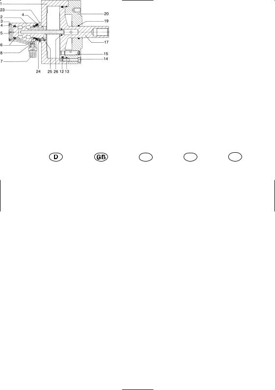
Der hydraulische |
|
The OV hydraulic |
|
OV cylindre hy- |
|
OV cilindro idrau- |
|
OV cilindro idrau- |
Vollspannzylinder |
|
cylinder without |
|
draulique sans |
|
lico senza pas- |
|
lico sin paso de |
OV |
|
through-hole |
|
passage de barre |
|
saggio barra |
|
barra |
|
|
|
|
|
|
|
|
|
Einzelteile – Important Components – Pièces détachées
Particolari importanti – Components más importants
|
|
|
Betätigungsdruck: |
max. 40 bar – min. 3 bar |
|
|
|
||
|
|
|
Operating pressure: |
max. 40 bar – min. 3 bar |
|
|
|
Pression de service: |
max. 40 bars – min. 3 bars |
|
|
|
Pressione d’esercizio: |
max. 40 bar – min. 3 bar |
|
|
|
Presión de servicio: |
max. 40 bar – min. 3 bar |
|
|
|
|
|
|
|
|
|
|
Teil |
|
|
|
|
|
F |
|
|
|
|
E |
|
|
|
|
|
|
|
|
|
|
|
|||
|
|
|
|
|
|
|
|
|
|
|||
|
Benennung |
|
Name |
|
Dèsignation |
|
Denominazione |
|
Designación |
|
||
01 |
|
Kolbengehäuse |
|
Piston housing |
|
Boîtier du piston |
|
Corpo stantuffo |
|
Caja del émbolo |
|
|
02 |
|
Verteilergehäuse |
|
Distributor housing |
|
Boîtier du distributeur |
|
Corpo distributore |
|
Caja del distribuidor |
|
|
03 |
|
O-Ring |
|
O-ring |
|
Joint |
|
toriqueO-ring |
|
Anillo |
toroidal |
|
04 |
|
Sicherungsring 2x |
|
Circlip 2 pcs |
|
Circlip 2 pcs |
|
Anello di sicur. 2 pezzi |
|
Anillo de retenc. 2 pzs |
|
|
05 |
|
Verschlußdeckel |
|
Cap |
|
Couvercle obturateur |
|
Coperchio |
|
Tapa de cierre |
|
|
06 |
|
Rillenkugellager 2x |
|
Deep-groove ball |
|
Roulement rainuré à |
|
Cuscinetta a sfere a |
|
Cojinete ranurado de |
|
|
|
|
|
|
bearing 2 pcs |
|
billes 2 pcs |
|
gola profonda 2 pezzi |
|
bolas 2 pzs |
|
|
07 |
|
Leckölabfluß |
|
Leak oil drain |
|
Pipe de fuite d’huile |
|
Scarico olio di ricupero |
|
Salida de aceite de fuga |
|
|
08 |
|
Radialwellendichtung |
|
Radial shaft seal |
|
Joint d’arbre |
|
Anello di tenuta radiale |
|
Empaque del árbol |
|
|
|
|
|
|
|
|
|
|
per albero |
|
|
|
|
12 |
|
Dichtring |
|
Seal ring |
|
Bague d’étanchéité |
|
Anello di tenuta |
|
Anillo de empaque |
|
|
13 |
|
O-Ring |
|
O-ring |
|
Joint torique |
|
O-ring |
|
Anillo toroidal |
|
|
14 |
|
Innensechskantschr. |
|
Hex. socket head cap |
|
Vis à six pans creux |
|
Vite ad esagono cavo |
|
Torn. con hexágono int. |
|
|
|
|
mit Sicherungsscheibe |
|
bolt with lock washer |
|
avec circlip |
|
con rosetta di sicur. |
|
con arandela de segur. |
|
|
15 |
|
Mitnehmerbolzen |
|
Driver |
|
Entraîneur |
|
Spina di trascinamento |
|
Perno arrastrador |
|
|
17 |
|
Kolben |
|
Piston |
|
Piston |
|
Stantuffo |
|
Embolo |
|
|
19 |
|
Dichtring |
|
Seal ring |
|
Bague d’étanchéité |
|
Anello di tenuta |
|
Anillo de empaque |
|
|
20 |
|
Zylinderdeckel (Flansch) |
|
Cylinder cover (flange) |
|
Couvercle du cylindre |
|
Coperchio cilindro |
|
Tapa del cilindro (brida) |
|
|
|
|
|
|
|
|
(bride) |
|
(flangia) |
|
|
|
|
23 |
|
Verteilerwelle |
|
Distributor shaft |
|
Arbre du distributeur |
|
Albero distributore |
|
Arbol del distribuidor |
|
|
24 |
|
Innensechskantschraube |
|
Hex. socket head cap |
|
Vis à six pans creux |
|
Vite ad esagono cavo |
|
Torn. con hexág. int. |
|
|
|
|
mit Sicherungsring |
|
bolt with lock washer |
|
avec circlip |
|
con rosetta di sicurezza |
|
con arandela de segurid. |
|
|
25 |
|
O-Ring |
|
O-ring |
|
Joint torique |
|
O-ring |
|
Anillo toroidal |
|
|
26 |
|
O-Ring |
|
O-ring |
|
Joint torique |
|
O-ring |
|
Anillo toroidal |
|
|
|
|
|
|
|
|
|
|
|
|
|
|
|
3
|
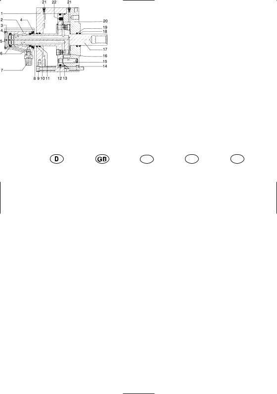
Der hydraulische |
|
The OVS hydrau- |
|
OVS cylindre hy- |
|
OVS cilindro |
|
|
OVS cilindro |
||
|
Vollspannzylinder |
|
lic cylinder |
|
draulique sans |
|
idraulico senza |
|
|
idraulico sin paso |
||
|
OVS |
|
without through- |
|
passage de barre |
|
passaggio barra |
|
de barra |
|||
|
|
|
hole |
|
|
|
|
|
|
|
|
|
|
Einzelteile – Important Components – Pièces détachées |
|
|
|
|
|||||||
|
Particolari importanti – Components más importants |
|
|
|
|
|
|
|
|
|||
|
|
|
|
|
|
|
Betätigungsdruck: |
|
|
|
||
|
|
|
|
|
|
|
|
|
|
|||
|
|
|
|
|
|
|
mit Alu-Gehäuse |
max. 40 bar – min. 3 bar |
||||
|
|
|
|
|
|
|
mit Stahlgehäuse |
max. 75 bar – min. 3 bar |
||||
|
|
|
|
|
|
|
Operating pressure: |
|
|
|
||
|
|
|
|
|
|
|
with aluminium housing |
max. 40 bar – min. 3 bar |
||||
|
|
|
|
|
|
|
with steel housing |
max. 75 bar – min. 3 bar |
||||
|
|
|
|
|
|
|
Pression de service: |
|
|
|
||
|
|
|
|
|
|
|
avec boîtier en aluminium |
max. 40 bars – min. 3 bars |
||||
|
|
|
|
|
|
|
avec boîtier en acier |
max. 75 bars – min. 3 bars |
||||
|
|
|
|
|
|
|
Pressione d’esercizio: |
|
|
|
||
|
|
|
|
|
|
|
con corpo in alluminio |
max. 40 bar – min. 3 bar |
||||
|
|
|
|
|
|
|
con corpo in acciao |
max. 75 bar – min. 3 bar |
||||
|
|
|
|
|
|
|
Presión de servicio: |
|
|
|
||
|
|
|
|
|
|
|
con caja de aluminio |
max. 40 bar – min. 3 bar |
||||
|
|
|
|
|
|
|
con caja de acero |
max. 75 bar – min. 3 bar |
||||
|
|
|
|
|
|
|
|
|
|
|
|
|
|
|
|
|
|
|
|
|
|
|
|
|
|
Teil |
|
|
|
|
|
F |
|
|
|
|
E |
|
|
|
|
|
|
|
|
|
|
|
|||
|
|
|
|
|
|
|
|
|
|
|||
|
Benennung |
|
Name |
|
Dèsignation |
|
Denominazione |
|
Designación |
|
||
01 |
|
Kolbengehäuse |
|
Piston housing |
|
Boîtier du piston |
|
Corpo stantuffo |
|
Caja del émbolo |
|
|
02 |
|
Verteilergehäuse |
|
Distributor housing |
|
Boîtier du distributeur |
|
Corpo distributore |
|
Caja del distribuidor |
|
|
03 |
|
O-Ring |
|
O-ring |
|
Joint |
|
toriqueO-ring |
|
Anillo |
toroidal |
|
04 |
|
Sicherungsring 2x |
|
Circlip 2 pcs |
|
Circlip 2 pcs |
|
Anello di sicur. 2 pezzi |
|
Anillo de retenc. 2 pzs |
|
|
05 |
|
Verschlußdeckel |
|
Cap |
|
Couvercle obturateur |
|
Coperchio |
|
Tapa de cierre |
|
|
06 |
|
Rillenkugellager 2x |
|
Deep-groove ball |
|
Roulement rainuré à |
|
Cuscinetta a sfere a |
|
Cojinete ranurado de |
|
|
|
|
|
|
bearing 2 pcs |
|
billes 2 pcs |
|
gola profonda 2 pezzi |
|
bolas 2 pzs |
|
|
07 |
|
Leckölabfluß |
|
Leak oil drain |
|
Pipe de fuite d’huile |
|
Scarico olio di ricupero |
|
Salida de aceite de fuga |
|
|
08 |
|
Radialwellendichtung |
|
Radial shaft seal |
|
Joint d’arbre |
|
Anello di tenuta radiale |
|
Empaque del árbol |
|
|
|
|
|
|
|
|
|
|
per albero |
|
|
|
|
09 |
|
Innensechskantschraube |
|
Hex. sock. head cap bolt |
|
Vis à six pans cr. pour |
|
Vite ad esagono cavo |
|
Tornillo con hexágono |
|
|
|
|
für Befest. von hinten |
|
for mount. from the rear |
|
la fixation par l’arrière |
|
con rosetta di sucurezza |
|
int. para la fijac. por detr. |
|
|
10 |
|
Abstreifring |
|
Wiper |
|
Bague racleur |
|
Anello raschiatoio |
|
Anillo rascador |
|
|
11 |
|
Dichtring |
|
Seal ring |
|
Bague d’étanchéité |
|
Anello di tenuta |
|
Anillo de empaque |
|
|
12 |
|
Dichtring |
|
Seal ring |
|
Bague d’étanchéité |
|
Anello di tenuta |
|
Anillo de empaque |
|
|
13 |
|
O-Ring |
|
O-ring |
|
Joint torique |
|
O-ring |
|
Anillo toroidal |
|
|
14 |
|
Innensechskantschr. |
|
Hex. socket head cap |
|
Vis à six pans creux |
|
Vite ad esagono cavo |
|
Torn. con hexágono int. |
|
|
|
|
mit Sicherungsscheibe |
|
bolt with lock washer |
|
avec circlip |
|
con rosetta di sicur. |
|
con arandela de segur. |
|
|
15 |
|
Mitnehmerbolzen |
|
Driver |
|
Entraîneur |
|
Spina di trascinamento |
|
Perno arrastrador |
|
|
16 |
|
Sicherheitseinrichtung |
|
Safety device |
|
Dispositif de sécurité |
|
Dispositivo di sicurezza |
|
Dispositivo de segur. |
|
|
17 |
|
Kolben |
|
Piston |
|
Piston |
|
Stantuffo |
|
Embolo |
|
|
18 |
|
Abstreifring |
|
Wiper |
|
Bague racleur |
|
Anello raschiatoio |
|
Anillo rascador |
|
|
19 |
|
Dichtring |
|
Seal ring |
|
Bague d’étanchéité |
|
Anello di tenuta |
|
Anillo de empaque |
|
|
20 |
|
Zylinderdeckel (Flansch) |
|
Cylinder cover (flange) |
|
Couvercle du cylindre |
|
Coperchio cilindro |
|
Tapa del cilindro (brida) |
|
|
|
|
|
|
|
|
(bride) |
|
(flangia) |
|
|
|
|
21 |
|
Entlüftungsschraube 2x |
|
Bleeding screw 2 pcs |
|
Vis de décompression |
|
Vite di sfiato 2 pezzi |
|
Tornillo de purga de |
|
|
|
|
|
|
|
|
2 pcs |
|
|
|
|
aire 2 pzs |
|
22 |
|
Überdruckventil |
|
Pressure control valve |
|
Valve de surpression |
|
Valvola di sovrappres- |
|
Válv. de sobrepresión |
|
|
|
|
|
|
|
|
|
|
sione |
|
|
|
|
|
|
|
|
|
|
|
|
|
|
|
|
|
4
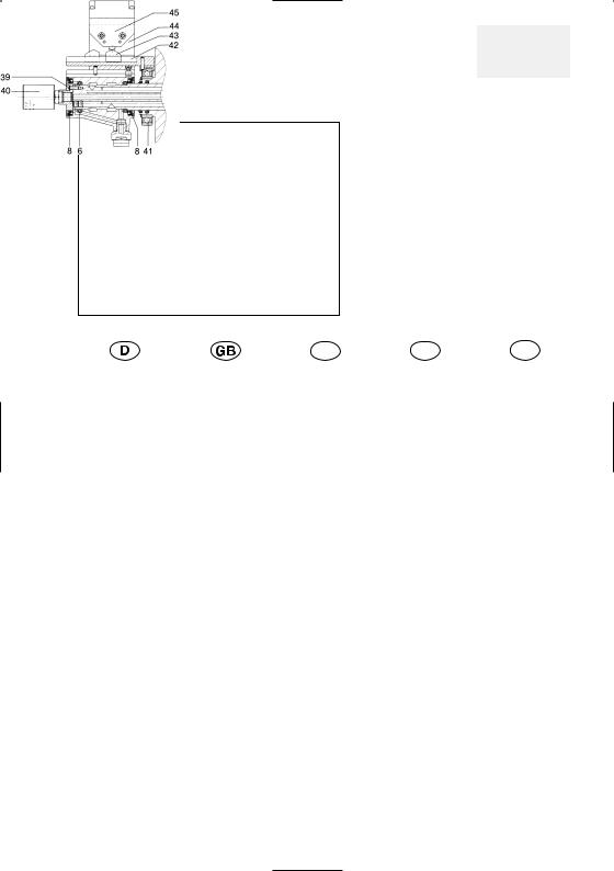
OVS – Ausführung |
|
OVS – with cen- |
|
OVS – avec |
|
OVS – con foro |
OVS – con taladro |
mit zentralem |
|
tral passage and |
|
alésage centrale et |
|
centrale e alimen- |
central y alimenta- |
Durchgang und |
|
rotating connec- |
|
raccord d’alimen- |
|
tazione rotante |
ción de giro |
Drehzuführung |
|
tion |
|
tation tournant |
|
|
|
|
|
|
|
|
|
|
|
Einzelteile – Important Components – Pièces détachées
Particolari importanti – Components más importants
Hubkontrolle durch Einzelgrenztaster DIN 43693
Stroke control by means of a single touch limit switch to
DIN 43693
Contrôle de course par interrupteur individuel de fin de course suivant DIN 43693
Controllo corsa mediante finecorsa singolo DIN 43693
Control de carrera por palpador individual de fin de carrera según DIN 43693
Teil |
|
|
|
|
|
F |
|
|
|
|
E |
|
|
|
|
|
|
|
|
|
|||
|
|
|
|
|
|
|
|
|
|||
|
Benennung |
|
Name |
|
Dèsignation |
|
Denominazione |
|
Designación |
||
|
|
zusätzlich: |
|
additional: |
|
en plus: |
|
in aggiunta: |
|
adicionalmente: |
|
06 |
|
Rillenkugellager |
|
Deep-groove ball |
|
Roulement rainuré à |
|
Cuscinetta a sfere a |
|
Cojinete ranurado de |
|
|
|
|
|
bearing |
|
billes |
|
gola profonda |
|
bolas |
|
08 |
|
Radialwellendichtung |
|
Radial shaft seal |
|
Joint d’arbre |
|
Anello di tenuta radiale |
|
Empaque del árbol |
|
|
|
|
|
|
|
|
|
per albero |
|
|
|
39 |
|
Sechskantschraube |
|
Hexagonal bolt |
|
Vis à six pans |
|
Vite ad esagono |
|
Anillo con hexágono |
|
|
|
(Gr. 85-105) |
|
(sizes 85-105) |
|
(réf. 85-105) |
|
(mis. 85-105) |
|
(tam. 85-105) |
|
|
|
Innensechskantschr. |
|
Hex. sock. head cap bolt |
|
Vis à six pans creux |
|
Vite ad esagono cavo |
|
Anillo con hexágono int. |
|
|
|
(Gr. 130-200) |
|
(sizes 130-200) |
|
(réf. 130-200) |
|
(mis. 130-200) |
|
(tam. 130-200) |
|
40 |
|
Drehzuführung |
|
Rotating connection |
|
Raccord d’alimentation |
|
Alimentazione rotante |
|
Alimentación de giro |
|
|
|
|
|
|
|
tournant |
|
|
|
|
|
41 |
|
Rillenkugellager |
|
Deep-groove ball |
|
Roulement rainuré à |
|
Cuscinetta a sfere a |
|
Cojinete ranurado de |
|
|
|
|
|
bearing |
|
billes |
|
gola profonda |
|
bolas |
|
42 |
|
Nockenhalter |
|
Cam support |
|
Support pour cames |
|
Supporto di camme |
|
Soporte de levas |
|
43 |
|
Steuernocken |
|
Control cam |
|
Came de commande |
|
Camma di comando |
|
Leva de mando |
|
|
|
|
|
|
|
|
|
|
|
|
|
44 |
|
Grenztasterführung |
|
Limit switch guide |
|
Guidage pour interr. |
|
Guida di finecorsa |
|
Guia de palpador |
|
|
|
|
|
|
|
de fin de course |
|
|
|
|
limite |
45 |
|
Einzelgrenztaster |
|
Single touch limit |
|
Interrupteur individuel |
|
Finecorsa singolo |
|
Palpador limite |
|
|
|
|
|
switch |
|
de fin de course |
|
|
|
|
individual |
|
|
|
|
|
|
|
|
|
|
|
|
5

Sicherheitshinweise und Richtlinien für den Einsatz von Hydraulik-Zylindern
1.Qualifikation des Bedieners
Personen, welche keine Erfahrungen im Umgang mit Spanneinrichtungen aufweisen, sind durch unsachgemäßes Verhalten, vor allem während der Einrichtearbeiten durch die auftretenden Spannbewegungen und -kräfte, besonderen Verletzungsgefahren ausgesetzt. Daher dürfen Spannvorrichtungen nur von Personen benutzt, eingerichtet oder instandgesetzt werden, welche hierzu besonders ausgebildet oder geschult sind bzw. über langjährige einschlägige Erfahrungen verfügen.
2.Verletzungsgefahren
Aus technischen Gründen kann diese Baugruppe teilweise aus scharfkantigen Einzelteilen bestehen. Um Verletzungsgefahren vorzubeugen ist bei daran vorzunehmenden Tätigkeiten mit besonderer Vorsicht vorzugehen!
2.1Eingebaute Energiespeicher
Bewegliche Teile, die mit Druck-, Zug-, sonstigen Federn oder mit anderen elastischen Elementen vorgespannt sind, stellen durch die darin gespeicherte Energie ein Gefahrenpotential dar. Dessen Unterschätzung kann zu schweren Verletzungen durch unkontrollierbare, geschoßartig umherfliegende Einzelteile führen. Bevor weitere Arbeiten durchgeführt werden können, ist diese gespeicherte Energie abzubauen. Spanneinrichtungen, die zerlegt werden sollen, sind deshalb mit Hilfe der zugehörigen Zusammenstellungszeichnungen auf derartige Gefahrenquellen hin zu untersuchen. Sollte das “Entschärfen” dieser gespeicherten Energie nicht gefahrlos möglich sein, ist die Demontage von autorisierten Mitarbeitern der Fa. Röhm durchzuführen.
2.2Überschreitung der zulässigen Drehzahl
Dieser Zylinder ist für umlaufenden Einsatz vorgesehen. Fliehkräfte - hervorgerufen durch überhöhte Drehzahlen bzw. Umfangsgeschwindigkeiten - können bewirken, daß sich Einzelteile lösen und dadurch zur potentiellen Gefahrenquelle für in der Nähe befindliche Personen oder Gegenstände werden. Dies gilt ebenfalls für Rotationsdichtungen, deren Verschleiß zu einem Druckverlust in den Zylinderkammern führen. Der Betrieb mit höheren als den für diese Vorrichtung vorgesehenen Drehzahlen ist aus o.g. Gründen nicht zulässig.
Die max. Drehzahl und Betätigungskraft/-druck sind auf dem Körper eingraviert und dürfen nicht überschritten werden. Das heißt, die Höchstdrehzahl der vorgesehenen Maschine darf nicht höher als die des Zylinders/Ölverteilers sein und ist daher ggf. zu begrenzen.
Selbst eine einmalige Überschreitung von zulässigen Werten kann zu Schäden führen und eine verdeckte Gefahrenquelle darstellen, auch wenn diese zunächst nicht erkennbar ist. In diesem Fall ist unverzüglich der Hersteller zu informieren, damit dieser eine Überprüfung der Funktionsund Betriebssicherheit durchführen kann. Nur so kann der weitere sichere Betrieb der Spanneinrichtung gewährleistet werden.
2.3Schmierung
Ein Trockenlauf des Verteilers ist nicht zulässig. Wird der Spannzylinder/Ölverteiler in Rotation versetzt, ist sicherzustellen, daß zumindest ein geringer Mediumdruck (min. 5 bar) an den Anschlüssen ansteht. Ansonsten ist mit Freßerscheinungen in den Verteilerspalten zu rechnen, was zum Versagen der Verdrehsicherung führen kann. Die Folge wäre ein möglicher Abriß der unter Druck stehenden Verbindungsleitungen.
2.4Filterung des zugeführten Mediums
Gegen Fremdkörper im Hydrauliköl ist ein Druckfilter einzusetzen. Empfohlen wird der Einbau am Hydraulikaggregat zwischen Pumpe und Steuerventil.
Die Filterfeinheit muß 0,01 mm absolut betragen.
Die Folgen mangelhafter Filterung entsprechen den unter 2.3 (Schmierung) dargestellten Ausführungen.
2.5Filterung des Kühlmittels
Bei Hohlspannzylindern mit Kühlmittelauffangschale können Späne über das Kühlmittel in die Kühlmittelauffangschale eingeschwemmt werden und deren Ablauf verstopfen. Dadurch kann der Flüssigkeitspegel soweit ansteigen, dass Kühlmittel in die Lagerung eindringen und diese zerstören kann.
Um dies zu vermeiden, muß das verwendete Kühlmittel gefiltert und die Kühlmittelauffangschale von Zeit zu Zeit gereinigt werden.
Wird der Durchgang des Hohlspannzylinders nicht benötigt, so sollte dieser futteroder zylinderseitig an der Schaltscheibe verschlossen werden.
2.6Verdrehsicherung am Verteilergehäuse
Das Verteilergehäuse muß grundsätzlich gegen Mitdrehen gesichert werden. Diese Verdrehsicherung ist am Leckölstutzen anzubringen.
Hinweis:
In der Praxis hat sich ein gabelartiger Halter als besonders geeignet erwiesen, der den Leckölstutzen beidseitig mit geringem Spiel umfaßt und dabei gleichzeitig einen axialen Schlitz aufweist, um Dehnungen und Toleranzen auszugleichen. Dieser Halter wird in der Regel am Spindelgehäuse befestigt.
2.7Anschlußleitungen
Auf Verteilergehäuse/-welle sollen keine zusätzlichen äußeren Kräfte, ausgenommen des Eigengewichts, wirken. Ansonsten droht ein vorzeitiger Verschleiß in den Lagern und im Verteilerspalt, entsprechend gelten die unter 2.3 (Schmierung) dargestellten Folgen. Alle Anschlußleitungen müssen deshalb biegsam sein und sind daher als Schlauchverbindungen zu fertigen.
2.8Befestigung und Austausch von Schrauben
Werden Schrauben ausgetauscht oder gelöst, kann mangelhafter Ersatz oder Befestigung zu Gefährdungen für Personen und Gegenständen führen. Deshalb muß bei allen Befestigungsschrauben, wenn nicht ausdrücklich anderweitig angegeben, grundsätzlich das vom Hersteller der Schraube, empfohlene und der Schraubengüte entsprechende Anzugsdrehmoment angewendet werden.
Es gilt für die gängigen Größen M5 - M24 der Güten 8.8, 10.9 und 12.9 nachfolgende Anzugsdrehmomententabelle.
Bei Ersatz der Originalschrauben ist im Zweifelsfall die Schraubengüte 12.9 zu verwenden. Bei Befestigungsschrauben für Zylinderdeckel und vergleichbare Elemente ist grundsätzlich die Güte 12.9 einzusetzen.
Alle Befestigungsschrauben, welche aufgrund ihres Verwendungszweckes öfters gelöst und anschließend wieder festgezogen werden müssen (z.B. wegen Umrüstarbeiten), sind im halbjährlichen Rhythmus im Gewindebereich und an der Kopfanlagefläche mit Gleitmittel (Fettpaste) zu beschichten.

Anschraubmomente in Nm:
Güte |
M5 |
M6 |
M8 |
M10 |
M12 |
M14 |
M16 |
M18 |
M20 |
M22 |
M24 |
|
8.8 |
5,9 |
10,1 |
24,6 |
48 |
84 |
133 |
206 |
295 |
415 |
567 |
714 |
Nm |
10.9 |
8,6 |
14,9 |
36,1 |
71 |
123 |
195 |
302 |
421 |
592 |
807 |
1017 |
Nm |
12.9 |
10 |
17,4 |
42,2 |
83 |
144 |
229 |
354 |
492 |
692 |
945 |
1190 |
Nm |
Durch äußere Einflüsse, wie z.B. Vibrationen, können sich unter ungünstigen Umständen selbst fest angezogene Schrauben lösen. Um dies zu verhindern, müssen alle sicherheitsrelevanten Schrauben (Spannmittelbefestigungsschrauben, Spannsatzbefestigungsschrauben u. ä.) in regelmäßigen Zeitabständen kontrolliert und ggf. nachgezogen werden.
2.9.Sicherheitsventile
Sicherheitsventile sollen bei Ausfall der Energie
(z. B. Stromversorgung) den Druckverlust und damit das Lösen der Spanneinrichtung verhindern. Es muss jedoch darauf hingewiesen werden, daß aufgrund der Reaktionszeiten oder Dichtungsverschleiß dennoch ein Druckverlust von etwa 20% des Ausgangsdrucks bei Hydraulikzylindern auftreten kann. Dies kann unter ungünstigen Umständen dazu führen, daß trotz Sicherheitsventile die Restspannkraft nicht mehr ausreicht, um das Werkstück im Spannmittel zu halten.
3.Kontrollen
1. Hubkontrolle: Wird das Spannmittel neu montiert, muss die Hubkontrolleinrichtung auf die neue Situation abgestimmt werden.
2. Wartungskontrollen: Die Zuverlässigkeit der Kraftspanneinrichtung kann nur dann gewährleistet werden, wenn die Wartungsvorschriften der Betriebsanleitung genau befolgt werden.
4.Umweltgefahren
Zum Betrieb einer Spanneinrichtung werden z.T. die unterschiedlichsten Medien für Schmierung, Kühlung etc. benötigt. Diese werden in der Regel über das Verteilergehäuse dem Spannmittel zugeführt. Die am häufigsten auftretenden sind Hydrauliköl, Schmieröl/-fett und Kühlmittel. Beim Umgang mit dem Spannmittel muß sorgfältig auf diese Medien geachtet werden, damit sie nicht in Boden bzw. Wasser gelangen können. Achtung Umweltgefährdung!
Dies gilt insbesondere:
-während der Montage/Demontage, da sich in den Leitungen und Kolbenräumen noch Restmengen befinden,
-für poröse, defekte oder nicht fachgerecht montierte Dichtungen,
-für Schmiermittel, die aus konstruktiven Gründen während des Betriebs aus dem Spannmittel austreten bzw. herausschleudern.
Diese austretenden Stoffe sollten daher aufgefangen und wiederverwendet bzw. den einschlägigen Vorschriften entsprechend entsorgt werden!
5.Sicherheitstechnische Anforderungen an kraftbetätigte Spanneinrichtungen:
5.1Die Maschinenspindel darf erst anlaufen, wenn der Spanndruck im Spannzylinder aufgebaut ist und die Spannung im zulässigen Arbeitssbereich erfolgt ist.
5.2Das Lösen der Spannung darf nur bei Stillstand der Maschinenspindel erfolgen können.
Eine Ausnahme ist dann zulässig, wenn der gesamte Ablauf ein Laden/Entladen im Lauf vorsieht und falls die Konstruktion von Verteiler/Zylinder dies erlaubt.
5.3Bei Ausfall der Spannenergie muß ein Signal die Maschinenspindel unverzüglich stillsetzen.
5.4Bei Ausfall der Spannenergie muß das Werkstück bis zum Spindelstillstand fest eingespannt bleiben.
5.5Bei Stromausfall und anschließender -wiederkehr darf keine Änderung der momentanen Schaltstellung erfolgen können.
6.Ersatzteile
Es wird darauf hingewiesen, daß ausschließlich ORIGINAL RÖHM-Ersatzteile bzw. Einbauteile von autorisierten Lieferanten der Fa RÖHM GmbH zu verwenden sind. Für alle Schäden, die durch die Verwendung von Fremdbauteilen entstehen, erlischt jegliche Haftung der Fa.
RÖHM GmbH.
Hinweis: Um Nachbestellungen von Ersatzteilen bzw. Einzelteilen reibungslos durchführen zu können, ist die Angabe der auf der Baugruppe eingravierten 6-stelligen Ident-Nummer und - wenn vorhanden - die Fabrikationsnummer erforderlich. Diese besteht aus einem Buchstaben gefolgt von 2 Ziffern und evtl. einer laufenden Nummer, angebracht entweder auf dem Typenschild oder in unmittelbarer Nähe zur Ident.-Nr.

Safety instructions and guidelines for the use of oil-operated cylinders
1.Qualification of Operating Personnel
Personnel inexperienced in the handling of clamping equipment may be in particular danger of injury from the clamping actions and forces as a result of inappropriate conduct, especially during set-up work.
For this reason the clamping devices may only be operated, set-up or repaired by personnel with special training or with many years of experience in this field.
2.Danger of Injury
For technical reasons this assembly may contain individual parts with sharp edges. Always proceed with utmost caution when working with the assembly to prevent the risk of injury!
2.1Contained forces
Moving parts pre-tensioned with pressure springs, tension springs or any other springs or elastic elements constitute a potential danger due to the forces they contain. Underestimation of these forces can cause serious injury resulting from uncontrollable, flying components travelling at the speed of projectiles. Prior to executing any further tasks, these contained forces must be released. For this reason the respective assembly drawings must always be procured prior to dismantling such a device and such potential hazards detected.
Should the discharge of such contained forces not be possible without any potential hazard, such elements should only be dismantled by authorised RÖHM personnel.
2.2Exceeding the Permissible Speed
This unit is designed for live operation. The centrifugal forces resulting from excessive speeds or rotational speeds may result in individual parts becoming detached and constituting a potential danger for personnel or objects in the vicinity. This also applies to rotary seals, which can cause a drop in pressure in the cylinder chambers if they are subjected to excessive wear.
Operation at higher speeds than those specified for this device is not permissible for the above-mentioned reasons.
The maximum speed and operating force/pressure are engraved on the body and may not be exceeded. Therefore the maximum speed of the machine used should not be higher than that of the cylinder/oil distributor and must therefore be limited.
Exceeding permissible values even once can cause damage and constitutes a latent source of danger, even if this is not immediately apparent. In such cases the manufacturer must be notified immediately so that the functionality and operational safety of the device can be checked. Only then can the continuing safe operation of the device be ensured.
2.3Lubrication
Dry operation of the distributor is not permitted.
If rotation of the clamping cylinder/oil distributor is initiated, ensure that a minimum media pressure is supplied to the connections (5 bar min.).
Pronounced wear must otherwise be expected on the distributor gaps which can cause failure of the torsional protection. A possible result could be that the pressurised connection lines are torn off.
2.4Filtering the supplied medium
A pressure filter to remove foreign bodies from the hydraulic oil must be installed. We recommend installing the filter on the hydraulic unit between the pump and the control valve.
The absolute filter gauge must be 0.01 mm.
Inadequate filtering can have the same consequences as described in section 2.3 (Lubrication).
2.5Coolant Filtering
In the case of hollow clamping cylinders with a coolant chip tray, chips can be flushed with the coolant into the coolant chip tray and clog the drain. This can cause the fluid level to rise so high that the coolant leaks into the bearings, thereby destroying them. To avoid this, the used coolant must be filtered and the coolant chip tray has to be cleaned from time to time.
If the hollow clamping cylinder passage is not needed, this should be sealed either on the chuck side or the cylinder side on the index plate.
2.6Torsional protection on the distribution housing
The distribution housing must always be secured against turning. This safety turn pin is to be attached at the leakage oil connection.
Note:
Experience has shown that a fork-shaped holder is particularly effective which encompasses the leakage oil connection on both sides with minimum clearance and which features an axial slot to compensate for expansion and tolerances. This holder is generally secured to the spindle housing.
2.7Connection lines
No additional external forces, except the unit weight, should be exerted on the distributor housing/shaft. This would cause premature wear on the bearings and the distributor gap with the consequences described in section 2.3 (Lubrication).
For this reason all connection lines must be flexible and should therefore all be hoses.
2.8Tightening and replacing screws
In the event that screws are loosened or replaced, danger to personnel or equipment can result from inadequate replacement or tightening. If not expressly stated otherwise, the tightening torque recommended by the screw manufacturer and which is suitable for the screw quality must be applied to all securing screws.
The values in the tightening torque table apply to the standard sizes M5 -- M24 in the qualities 8.8, 10.9 and 12.9.
When replacing the original screws the quality 12.9 should be used if in doubt. The quality 12.9 must always be used for cylinder covers and comparable elements.
The threads and head contact surfaces of all securing screws which are frequently released and retightened due to their application (e.g. for retooling) must be coated with a lubricant (grease paste) at six-monthly intervals.
Even securely tightened screws can become loose under adverse outside conditions such as, for instance, vibrations. In order to prevent this happening, all safety-rela- ted screws (clamping fixture fastening screws), clamping set fastening screws etc.) must be checked and, if necessary, tightened at regular intervals.
2.9Safety valves
In the event of a power failure (e.g. electric power supply) the safety valves must prevent loss of pressure, which would release the clamping device. It must, however, be pointed out that, due to the reaction times or seal wear, a pressure loss of approx. 20% of the output pressure of hydraulic cylinders may be experienced.
In unfavourable circumstances and despite the fact that safety valves have been fitted this can lead to a situation where the residual clamping force is no longer sufficient to retain the workpiece in the clamping device.

Tightening torques in Nm:
Class |
M5 |
M6 |
M8 |
M10 |
M12 |
M14 |
M16 |
M18 |
M20 |
M22 |
M24 |
|
8.8 |
5,9 |
10,1 |
24,6 |
48 |
84 |
133 |
206 |
295 |
415 |
567 |
714 |
Nm |
10.9 |
8,6 |
14,9 |
36,1 |
71 |
123 |
195 |
302 |
421 |
592 |
807 |
1017 |
Nm |
12.9 |
10 |
17,4 |
42,2 |
83 |
144 |
229 |
354 |
492 |
692 |
945 |
1190 |
Nm |
3.Controls
1. Stroke control: When the clamping device has been changed, the stroke control must be adjusted to the new condition.
2. Maintenance controls: The reliability of clamping equipment can be ensured only if the servicing instructions of the manual are obeyed exactly.
4.Environmental Hazards
A wide range of media are required during operation of a clamping device for lubrication, cooling etc. This are normally distributed to the clamping device via the distribution housing. The most common substances used are hydraulic oil, lubricating oil/ grease and cooling agents. When handling the clamping device care must be taken to ensure that these substances do not come in contact with the soil or water. Warning, environmental hazard!
This applies in particular
-during assembly/disassembly, as residues can be contained in the pipes and piston shafts,
-to porous, defective or incorrectly mounted seals,
-to lubricants which are emitted or ejected from the clamping device during operation for constructional reasons.
These discharged substances should therefore be collected and either re-used or disposed of in accordance with valid regulations!
5.Safety requirements for power clamping equipment:
5.1The machine spindle may not start until the clamping pressure has been reached in the clamping cylinder and
clamping has been effected within the permissible working range.
5.2The pressure may only be released when the machine spindle is stationary.
Exceptions are only permissible if the complete machining sequence of loading and unloading is performed with the spindle in motion and the design of the distributor/cylinder permits this.
5.3A signal must be emitted to stop the spindle immediately in the event of a failure of the clamping power.
5.4The workpiece must remain tightly clamped until the spindle is stationary in the event of a failure of the clamping power.
5.5Changes of the current switch position should not be possible during an electrical power failure and subsequent restoration.
6.Spare Parts
Only use ORIGINAL RÖHM spare parts or components obtained from authorised RÖHM suppliers. RÖHM GmbH does not accept any liability for damage resulting from the employment of parts supplied by other manufacturers.
Note: For simple ordering of spare parts or individual components always state the 6-digit ID number engraved on the assembly and, if available, the works number. This comprises a letter with two digits and possibly a series number, stated either on the rating plate or next to the ID number.
 Loading...