

Page 1

Heinrich-Röhm-Str. 50
89567 Sontheim/Brenz - GERMANY
Tel. (49)7325 / 16 0
www.roehm.biz
Original Bedienungsanleitung 1263248
gültig für
Einzugskraftmessgerät F-senso
KLEIN
Einzugskraftmessgerät F-senso
Typ: 0-15 kN Typ: 10-100 kN
ID.-Nr.: 1266341
(Grundgerät)
ID.-Nr.: 1255729
(Grundgerät)
1. Bestimmungsgemäße Verwendung ................................................................. 2
2. Allgemeine Information ..................................................................................... 3
3. Gefahrenhinweise.............................................................................................. 4
4. Bedienung .......................................................................................................... 5
4.1. Übersicht des Grundgerätes .......................................................................... 5
4.2. Inbetriebnahme.............................................................................................. 5
4.3. Adapter montieren ......................................................................................... 5
4.4. Positionieren der Stellhülse ........................................................................... 7
4.5. Messung durchführen .................................................................................... 8
5. Technische Daten .............................................................................................. 9
6. Gewährleistungsausschluss ............................................................................ 9
7. Lieferumfang und Zubehör ............................................................................. 10
8. Kalibrierzertifikat Firma HKM Messtechnik …………………………… Anhang
Version 2 Erstellungsdatum: 01.03.2014
Page 2
Bestimmungsgemäße Verwendung
Vielen Dank, dass Sie sich für das Einzugskraftmessgerät F-senso der Firma RÖHM
entschieden haben. Lesen Sie die Bedienungsanleitung sorgfältig durch, bevor Sie
das Gerät in Betrieb nehmen und halten Sie diese immer am Einsatzort bereit.
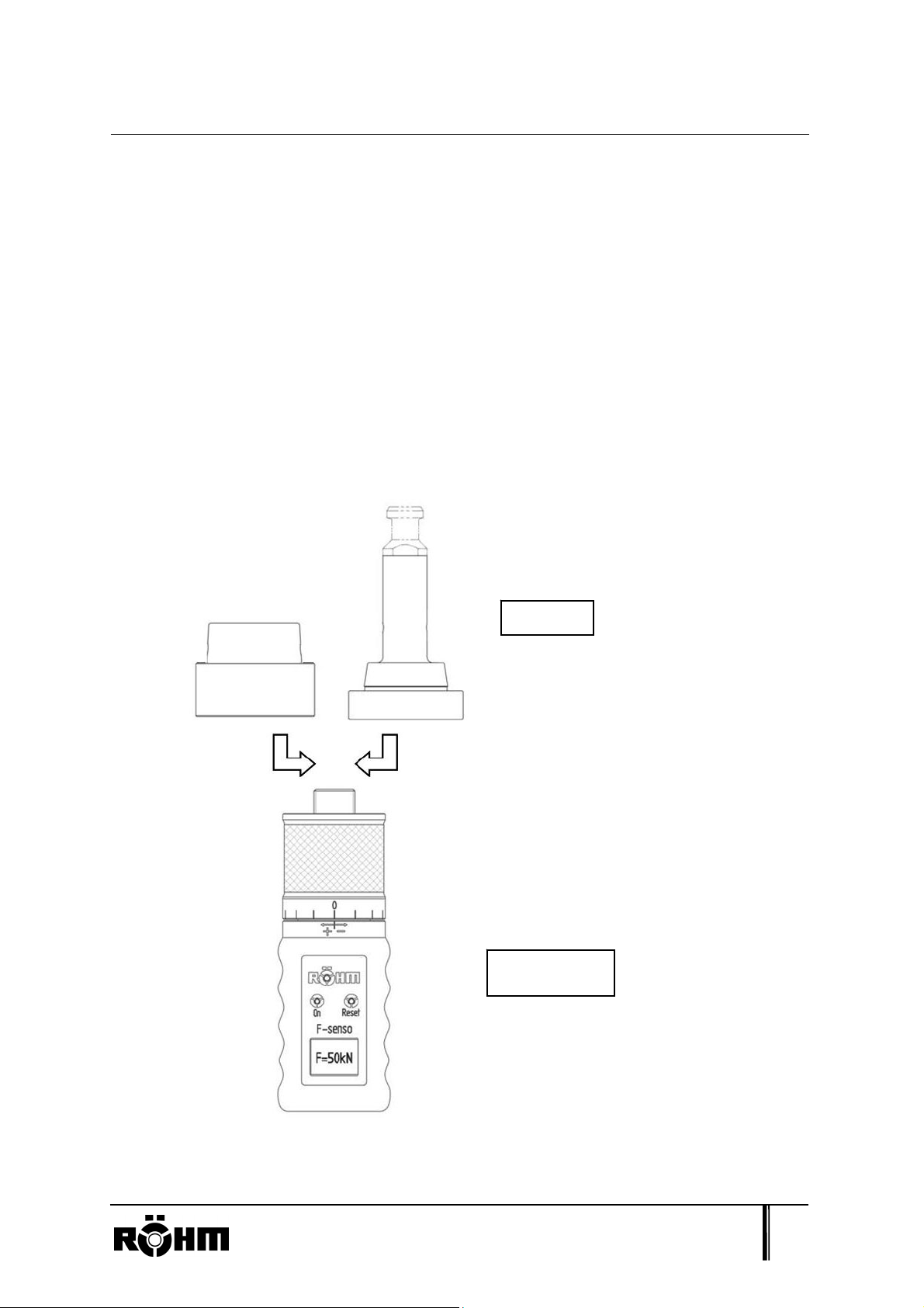
1. Bestimmungsgemäße Verwendung
Das Einzugskraftmessgerät F-senso wird zum Messen der axialen Einzugskraft von
Werkzeugaufnahmen in die Maschinenspindel verwendet. Es können Kräfte an
unterschiedlichen Werkzeugaufnahmen gemessen werden, wie z.B. Steilkegel (SK),
Hohlschaftkegel (HSK). Dies wird durch Verwendung unterschiedlicher Adapter
realisiert.
Adapter
Grundgerät
Das Gerät darf nur bei stehender Maschinenspindel eingesetzt werden!
Heinrich-Röhm-Str. 50, 89567 Sontheim/Brenz., GERMANY, Tel. (49)7325/16-0 2
Page 3

Allgemeine Information
2. Allgemeine Information
- Halten Sie die vorgegebenen Montage oder Bedienschritte ein.
- Die Bedienung/Montage dieses Produktes darf nur durch qualifizierte Fachkräfte
erfolgen.
- Außer den in der Bedienungs- und Montageanleitung zum Produkt
beschriebenen Tätigkeiten dürfen am Produkt keine Veränderungen, An- und
Umbauten oder Wartungsarbeiten vorgenommen werden.
- Das Messgerät kann durch Überbelastung von mehr als 3% vom Maximalwert
beschädigt werden.
- Transportieren und lagern Sie das Gerät sorgfältig in dem mitgelieferten Koffer.
- Treten am Produkt Störungen auf, nehmen Sie bitte Kontakt mit dem Hersteller
auf.
- Nicht bei Gefahr von Spritzwasser einsetzen!
- Das Gerät wurde nach EMV-Vorschriften der DIN EN 61000-6-3 und
61000-4-2/3 getestet.
Heinrich-Röhm-Str. 50, 89567 Sontheim/Brenz., GERMANY, Tel. (49)7325/16-0 3
Page 4
Gefahrenhinweise
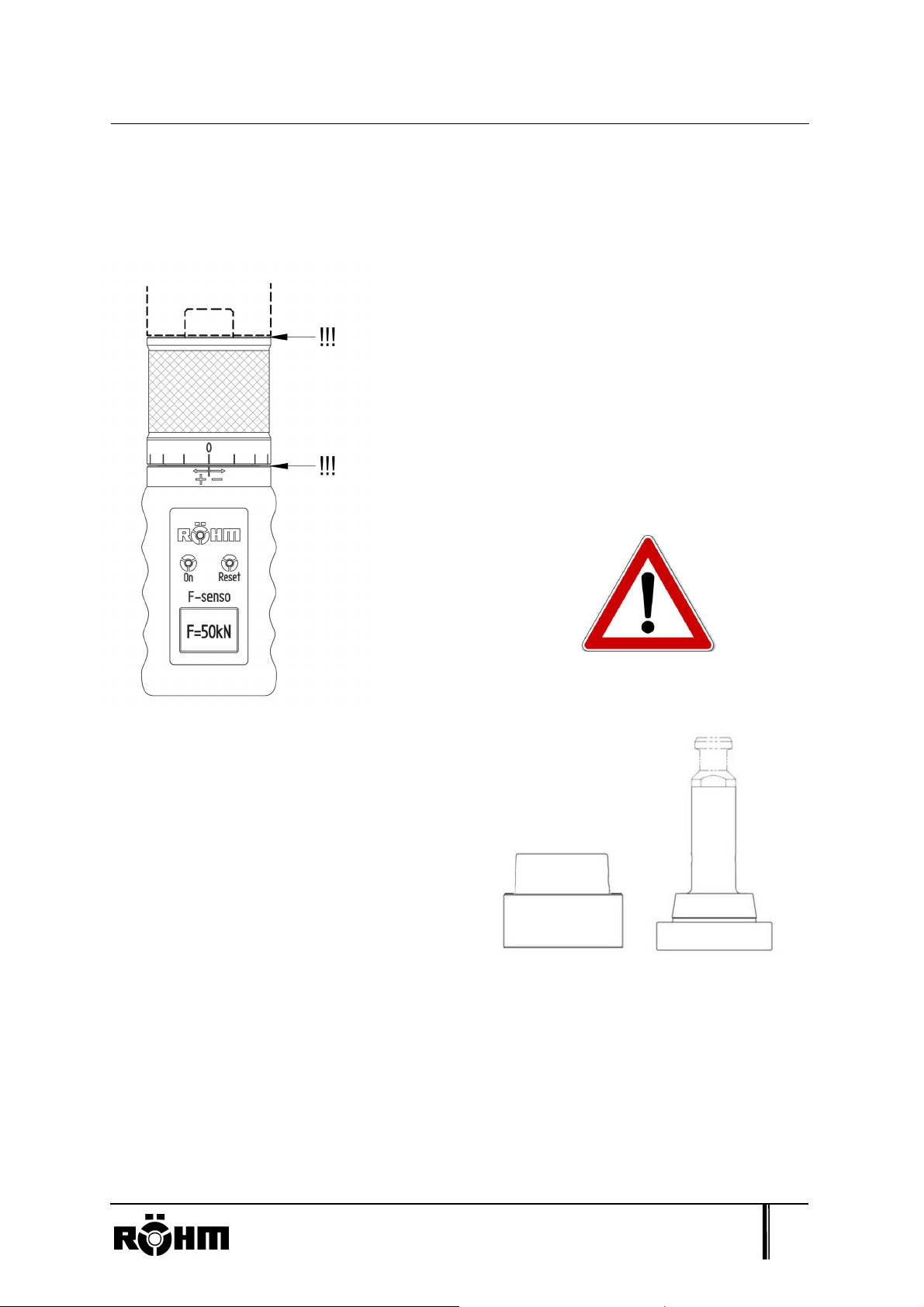
3. Gefahrenhinweise
!!! Quetschgefahr !!! Handschutz !!!
Im oberen Bereich, an der Anschlagfläche der
Adapter, besteht Quetschgefahr.
Deshalb sollte beim Messvorgang erhöhte Vorsicht
geboten sein.
Ebenfalls besteht Quetschgefahr beim Verstellen
der Stellhülse.
Achtsamkeit ebenso beim Handhaben der
Adapter, da die einzelnen Adapterteile
nicht fest miteinander verbunden sind,
sondern nur zueinander arretiert sind.
Heinrich-Röhm-Str. 50, 89567 Sontheim/Brenz., GERMANY, Tel. (49)7325/16-0 4
Page 5

Bedienung
4. Bedienung
4.1. Übersicht des Grundgerätes
4.2. Inbetriebnahme
Bitte setzen Sie zuerst eine 9V Blockbatterie (nicht im Lieferumfang enthalten) in das
gekennzeichnete Batteriefach ein.
4.3. Adapter montieren
Voraussetzungen
Es dürfen nur passende Adapter der Firma RÖHM montiert werden.
Das Adapteranschlussgewinde M24 x 1,5 und die Planfläche müssen in
sauberem und unbeschädigtem Zustand sein.
Heinrich-Röhm-Str. 50, 89567 Sontheim/Brenz., GERMANY, Tel. (49)7325/16-0 5
Page 6
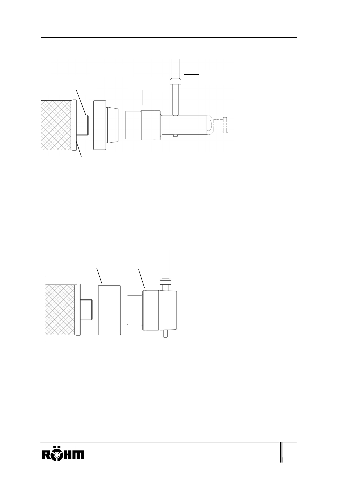
Bedienung
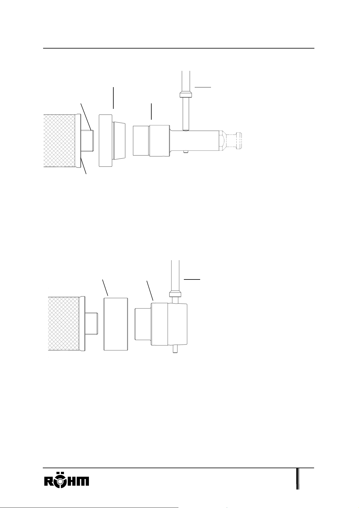
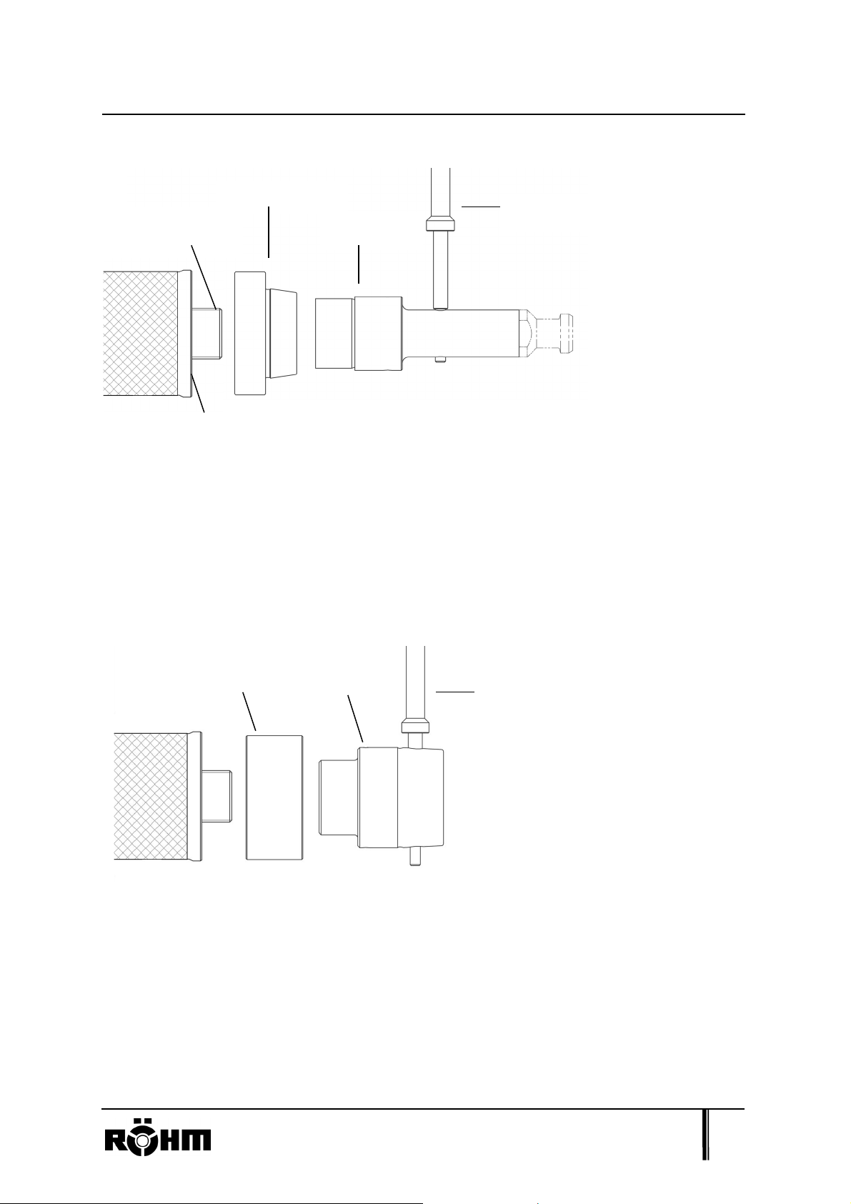
Montieren SK-Adapter
Adapteranschlussgewinde
Messkegel
Zugbolzen
Planfläche
1. Messkegel auf das Grundgerät aufsetzen.
Montagestab
2. Zugbolzen auf Grundgerät aufschrauben.
3. Zugbolzen mit Montagestab auf Grundgerät handfest anziehen.
Montieren HSK-Adapter
Distanzstück
Messkegel
Montagestab
1. Distanzstück auf das Grundgerät aufsetzen.
2. Messkegel auf Grundgerät aufschrauben.
3. Messkegel mit Montagestab auf Grundgerät handfest anziehen.
Heinrich-Röhm-Str. 50, 89567 Sontheim/Brenz., GERMANY, Tel. (49)7325/16-0 6
Page 7
Bedienung
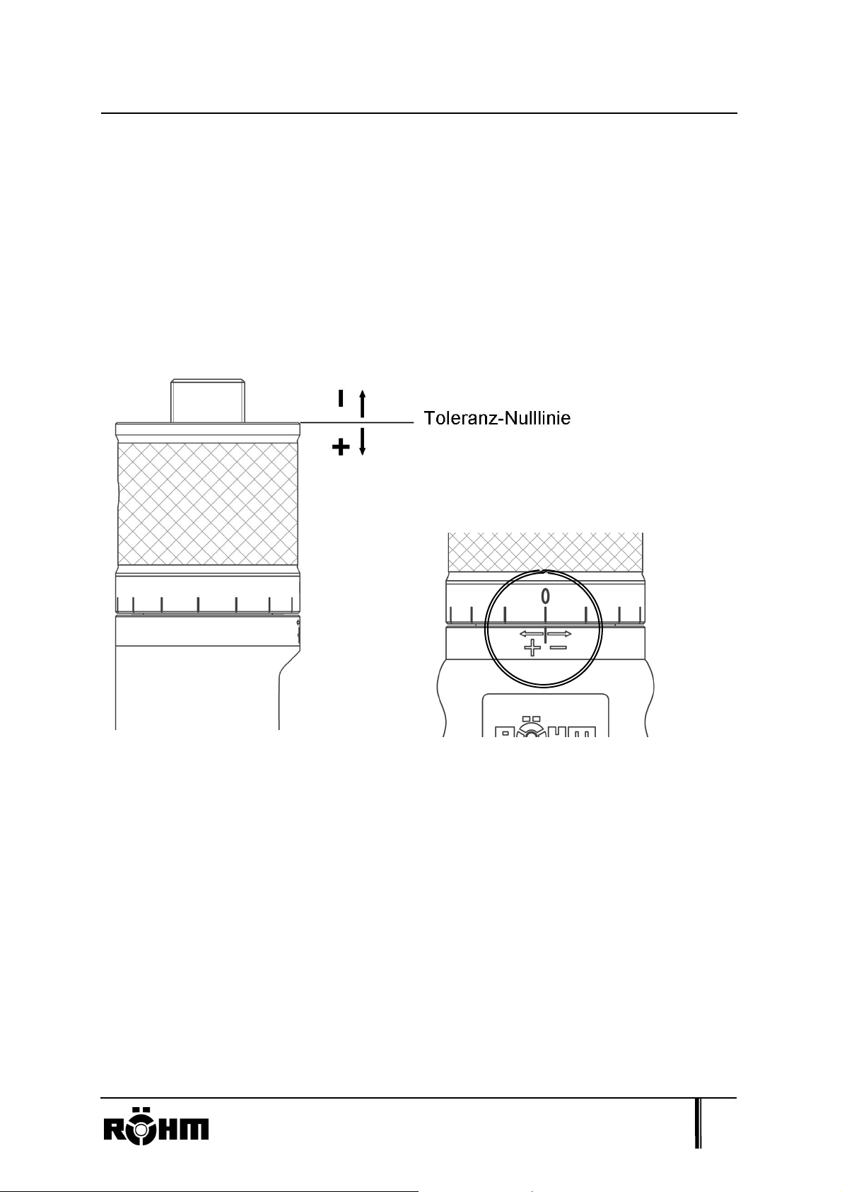
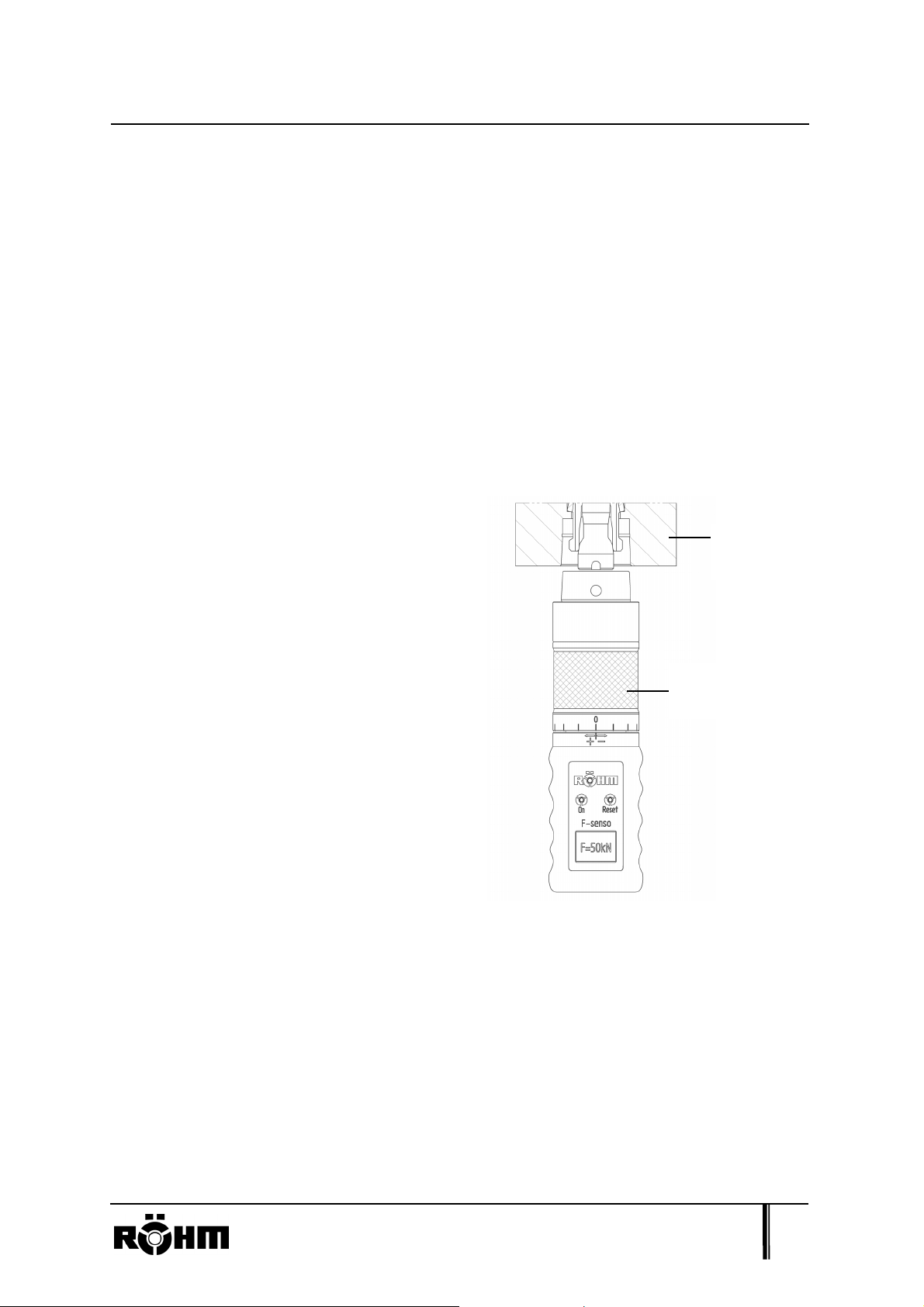
4.4. Positionieren der Stellhülse
Mit dem Einzugskraftmessgerät F-senso ist es möglich, Toleranzen zwischen
Spindel und Werkzeug zu berücksichtigen.
In abgebildeter Position der Stellhülse (s. Kreismarkierung rechtes Bild) ist zu
messen, wenn kein Verschleiß an Werkzeugaufnahme, Spindelwelle und Spannsatz
vorhanden ist. Durch das Verstellen der Stellhülse kann ein Verschleiß bei der
Messung berücksichtigt werden.
Am Anfang die Stellhülse auf gewünschte Position einstellen.
Eine Rasterung der Stellhülse entspricht einer axialen Verschiebung um
0,1 mm.
Die Stellhülse muss nach jedem Verstellen exakt eingerastet sein.
Das Drehen der Stellhülse in „+“ Richtung bedeutet eine Verlängerung des
Zugelements am Adapter; Drehen in „-“ Richtung eine Verkürzung.
(Anders ausgedrückt, eine Verschiebung der Planfläche zur Spannschräge des
Adapters).
Heinrich-Röhm-Str. 50, 89567 Sontheim/Brenz., GERMANY, Tel. (49)7325/16-0 7
Page 8
A
Bedienung
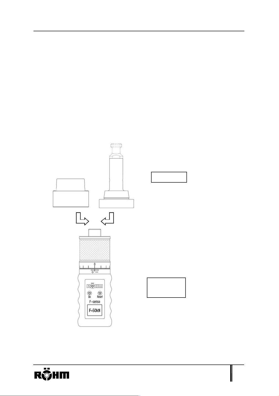
4.5. Messung durchführen
Bitte montieren Sie entsprechende Adapter (siehe Kap. 4.3), bevor Sie das Gerät
einschalten. Kontrollieren Sie die Position der Stellhülse (s. Kap. 4.4). Dies muss vor
jeder Messung eingerastet sein und darf nicht auf Anschlag gedreht sein.
Schalten Sie das Gerät ein, indem Sie die On-Taste drücken. Danach erscheint kurz
ein Informationsbildschirm mit der Seriennummer. Nun wechselt das Gerät in den
Messmodus. Sie können die Messung beginnen.
Führen Sie das Gerät mit Adapter
Spindelwelle
zentrisch und gerade gehalten
in die Spindelwelle ein.
Betätigen Sie die Werkstückspannung,
indem Sie die Einzugskraft einleiten.
Messgerät mit
dapter (hier HSK)
Es wird die aktuell anstehende
Einzugskraft, wie auch darunter die
maximale Einzugskraft angezeigt.
Durch wiederholtes Drücken der On-Taste schaltet sich das Gerät wieder aus.
Gleiches erfolgt durch die AUTO-OFF Funktion, wenn das Gerät 2 Min. ungebraucht
ist.
Heinrich-Röhm-Str. 50, 89567 Sontheim/Brenz., GERMANY, Tel. (49)7325/16-0 8
Page 9

(
5. Technische Daten
Technische Daten
Grundgerät
1255729 1266341
Messbereich 10-100 kN
Auflösung
Messprinzip
Kraftsensor mit Dehnungsmessstreifen
Betriebsarten
Genauigkeit
Überlast
Anzeige
Versorgung
Spezifikation siehe beigefügtes Dokument)
Temperaturbereich
Gewicht
(Grundgerät)
ca. 1,5 kg
0-15 kN
0,1 kN
Anzeige des aktuellen Wertes
Anzeige des Maximalwertes
0,25% (f.s.)
max. 3%
LCD Display
9V Blockbatterie
5 - 40° C
ca. 1 kg
Abmessungen
ca. Ø66 mm; L=189 mm
ca. Ø66 mm; L=172 mm
(Grundgerät)
6. Gewährleistungsausschluss
Treten Schäden, verursacht durch
- Nichterfüllung der schriftlichen Anweisungen (Bedienungsanleitung) des
Verkäufers
- Natürlichen Verschleiß
- Einwirkung von höherer Gewalt
- Fehlbedienung jeglicher Art oder verursacht durch nicht sachgemäßen Einsatz
oder Betrieb
- geänderte Umgebungsbedingungen
auf, erlischt der Garantieanspruch. RÖHM übernimmt somit keine Haftung mehr.
Heinrich-Röhm-Str. 50, 89567 Sontheim/Brenz., GERMANY, Tel. (49)7325/16-0 9
Page 10
Lieferumfang und Zubehör
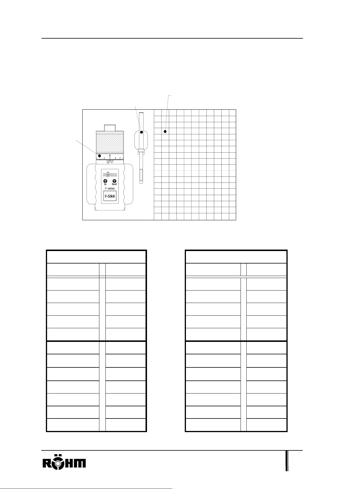
7. Lieferumfang und Zubehör
Folgende Abbildung zeigt den gelieferten Kofferinhalt.
Nachstehend finden Sie die ID.-Nr. der unterschiedlichen Adapter
Grundgerät 1255729
Grundgerät 1266341
Adapter ID.-Nr. Adapter ID.-Nr.
HSK-A 50
HSK-A 63
HSK-A 80
HSK-A 100
HSK-A 125
SK 40
SK 50
SK 60
SPK100
1255738
1255739
1255740
1255741
1255742
1255744
1255745
1255746
1288317
HSK-A 25
HSK-A 32
HSK-A 40
SK 30
1255735
1255736
1255737
1255743
SPK110
SPK125
SPK140
1296094
1288319
1288320
Heinrich-Röhm-Str. 50, 89567 Sontheim/Brenz., GERMANY, Tel. (49)7325/16-0 10
Page 11

Heinrich-Röhm-Str. 50
89567 Sontheim/Brenz - GERMANY
Tel. (49)7325 / 16 0
www.roehm.biz
Original User's Guide 1263248
applies to
F-senso pull-in force
measurement device
SMALL
F-senso pull-in force measurement
device
Type: 0-15 kN Type: 10-100 kN
ID no.: 1266341
(base unit)
ID no.: 1255729
(base unit)
1. Usage in accordance with the intended purpose ........................................... 2
2. General Information: ......................................................................................... 3
3. Hazard warnings ................................................................................................ 4
4. Operation ........................................................................................................... 5
4.1. Overview of the base unit .............................................................................. 5
4.2. Getting started ............................................................................................... 5
4.3. Mounting the adapter ..................................................................................... 5
4.4. Positioning of the adjustment sleeve ............................................................. 7
4.5. Carrying out the measurement ...................................................................... 8
5. Technical data ................................................................................................... 9
6. Warranty exclusion ........................................................................................... 9
7. Delivery contents and accessories ................................................................ 10
8. Calibration certificate from HKM Messtechnik …………………… Appendix
Version 2 Creation date: 01.03.2014
Page 12

Usage in accordance with the intended purpose
Thank you very much for choosing the F-senso pull-in measurement device from
RÖHM. Please read through the user's guide carefully before using the device and
always keep it at the place where the device is being used.
1. Usage in accordance with the intended purpose
The F-senso pull-in measurement device is used to measure the axial pull-in force of
tool clamping systems in the machine spindle. Forces can be measured on different
tool clamping systems such as, for example, a steep-angle taper (SK) or hollow
shank taper (HSK). This is realised through the use of different adapters.
Adapter
Base unit
The device may only be used on an upright machine spindle.
Heinrich-Röhm-Str. 50, 89567 Sontheim/Brenz., GERMANY, Tel. (49)7325/16-0 2
Page 13

General Information:
2. General Information:
- Comply with the given assembly or operating steps.
- This product may only be operated/assembled by qualified experts.
- Other than the activities described in the user's and installation guide, there must
be no other changes, attachments, modifications or maintenance work on the
product.
- The measurement device can be damaged by overloading it by more than 3% of
the maximum value.
- Transport and store the device in the provided case.
- If the device has any malfunctions, please contact the manufacturer.
- Do not use if there is a risk of water spray.
- The device was tested in accordance with the EMC regulations of DIN EN
61000-6-3 and 61000-4-2/3.
Heinrich-Röhm-Str. 50, 89567 Sontheim/Brenz., GERMANY, Tel. (49)7325/16-0 3
Page 14
Hazard warnings
3. Hazard warnings
!!! Nipping danger !!! Hand protection !!!
There is a nipping danger in the top section on the
locating face of the adapter.
Therefore, greater care is called for during the
measurement process.
There is also a danger of nipping when adjusting
the adjustment sleeve.
Care is also required when handling the
adapter, because the individual adapter
parts are not connected together tightly,
rather they are only resting on each other.
Heinrich-Röhm-Str. 50, 89567 Sontheim/Brenz., GERMANY, Tel. (49)7325/16-0 4
Page 15
4. Operation
4.1. Overview of the base unit
Operation
Adapter connection
thread
Adjustment sleeve
with scale
Operating buttons
(On, Reset)
Grip
Battery compartment
4.2. Getting started
First of all, please insert the monobloc battery of 9V (not included in the scope of
supply) into the designated battery compartment.
4.3. Mounting the adapter
Requirements
Only matching adapters from RÖHM may be mounted.
The adapter connection thread M24 x 1.5 and the end face must be clean and
not damaged.
Heinrich-Röhm-Str. 50, 89567 Sontheim/Brenz., GERMANY, Tel. (49)7325/16-0 5
Page 16
Operation
Mounting the SK adapter
Adapter
connection thread
Measuring taper
Tension bolt
end face
1. Put the measuring taper on the base unit.
Mounting bar
2. Screw the tension bolt onto the base unit.
3. Tighten the tension bolt on the base unit with the mounting bar until it is finger
tight.
Mounting the HSK adapter
Measuring taper
Spacer
Mounting bar
1. Put the spacer on the base unit.
2. Screw the measuring taper onto the base unit.
3. Tighten the measuring taper on the base unit with the mounting bar until it is
finger tight.
Heinrich-Röhm-Str. 50, 89567 Sontheim/Brenz., GERMANY, Tel. (49)7325/16-0 6
Page 17

Operation
4.4. Positioning of the adjustment sleeve
With the F-senso pull-in measurement device, it is possible to take tolerances
between the spindle and tool into consideration.
You should measure with the adjusting sleeve in the position shown in the illustration
(see circular marking on the right picture) if there is no wear on the tool clamping
system, spindle shaft and clamp set. Wear can be taken into consideration for the
measurement by adjusting the adjusting sleeve.
At the beginning, set the adjustment sleeve to the desired position.
One grid mark on the adjusting sleeve corresponds to an axial displacement of
0.1 mm.
The adjusting sleeve must be snapped into place exactly after each
adjustment.
Turning the adjustment sleeve in the "+" direction means lengthening the pull-
in element on the adapter; turning in the "-" direction means shortening it.
(In other words, displacement of the end face towards the taper of the
adapter).
Heinrich-Röhm-Str. 50, 89567 Sontheim/Brenz., GERMANY, Tel. (49)7325/16-0 7
Page 18
Operation
4.5. Carrying out the measurement
Please mount the respective adapter (see chapter 4.3) before switching on the
device. Check the position of the adjustment sleeve (see chapter 4.4). It must be
snapped into place before each measurement and must not be twisted as far as it
goes.
Switch on the device by pressing the On button. An information screen with the serial
number appears for a brief moment. Then, the device changes to measurement
mode and you can begin the measurement.
Guide the device with the adapter
into the spindle shaft centred and
Spindle
shaft
straight.
Actuate the tool clamping by initiating
the pull-in force.
Measuring device
with the adapter
The currently existing pull-in force is
shown as well as the maximum pull-in
force below it.
The device can be switched off by pressing the On button once again. The same
thing happens with the AUTO-OFF function if the device is not used for 2 minutes.
Heinrich-Röhm-Str. 50, 89567 Sontheim/Brenz., GERMANY, Tel. (49)7325/16-0 8
Page 19

5. Technical data
Technical data
Base unit
1255729 1266341
Measuring range 10-100 kN
Resolution
Measuring principle
Power sensor with a strain gauge
Display of the current value
Modes of Operation
Display of maximum value
Accuracy
Overload
Display
9V block battery (see specification in the
Power supply
document transmitted in annex)
Temperature range
Weight
(Base unit)
approx. 1.5 kg
0-15 kN
0.1 kN
0.25% (f.s.)
max. 3%
LCD display
5 - 40° C
approx. 1 kg
Dimensions
ca. Ø66 mm; L=189 mm
ca. Ø66 mm; L=172 mm
(Base unit)
6. Warranty exclusion
If damage occurs that is caused by
- non-compliance with the written instructions (user's guide) of the seller
- natural wear and tear
- force majeure
- misuse of any type caused by improper use or operation
- changed environmental conditions,
then any warranty claim is voided. Consequently, RÖHM assumes no liability.
Heinrich-Röhm-Str. 50, 89567 Sontheim/Brenz., GERMANY, Tel. (49)7325/16-0 9
Page 20

p
Delivery contents and accessories
7. Delivery contents and accessories
The following illustration shows the contents delivered with the case.
Plastic foam grating for holding
Mounting bar
Base unit
different ada
ters
The ID numbers of the different adapters are found in the following.
Base unit 1255729
Base unit 1266341
Adapter ID. no.: Adapter ID. no.:
HSK-A 50
HSK-A 63
HSK-A 80
HSK-A 100
HSK-A 125
SK 40
SK 50
SK 60
SPK100
1255738
1255739
1255740
1255741
1255742
1255744
1255745
1255746
1288317
HSK-A 25
HSK-A 32
HSK-A 40
SK 30
1255735
1255736
1255737
1255743
SPK110
SPK125
SPK140
1296094
1288319
1288320
Heinrich-Röhm-Str. 50, 89567 Sontheim/Brenz., GERMANY, Tel. (49)7325/16-0 10
Page 21

Heinrich-Röhm-Str. 50
89567 Sontheim/Brenz – GERMANY
Tel. (49)7325 / 16 0
www.roehm.biz
Mode d’emploi original 1263248
Valable pour
Dispositif de mesure de la force de
traction F-senso
PETIT
Dispositif de mesure de la force de
traction F-senso
Type : 0-15 kN Type : 10-100 kN
No. ID : 1266341
(Dispositif principal)
No. ID : 1255729
(Dispositif principal)
1. Utilisation conforme .......................................................................................... 2
2. Informations générales ..................................................................................... 3
3. Avertissements .................................................................................................. 4
4. Utilisation ........................................................................................................... 5
4.1. Vue d’ensemble du dispositif principal ........................................................... 5
4.2. Mise en service .............................................................................................. 5
4.3. Montage de l’adaptateur ................................................................................ 5
4.4. Positionnement de la douille de réglage ........................................................ 7
4.5. Procéder aux mesures .................................................................................. 8
5. Données techniques ......................................................................................... 9
6. Exclusion de garantie ....................................................................................... 9
7. Contenu de la livraison et accessoires ......................................................... 10
8. Certificat de calibrage entreprise HKM Messtechnik ……………… Annexe
Version 2 Date de création : 01.03.2014
Page 22

Utilisation conforme
Nous vous remercions pour l’achat du dispositif de mesure de la force de traction
F-senso de l’entreprise RÖHM. Veuillez lire soigneusement le mode d’emploi avant
toute utilisation de l’appareil et conservez-le toujours à portée de main sur le lieu
d’utilisation.
1. Utilisation conforme
Le dispositif de mesure de la force de traction F-senso est utilisé pour la mesure de
la force de traction axiale des porte-outils dans le cône de la machine. Les forces
peuvent être mesurées sur divers porte-outils, par exemple sur les cônes SA ou les
cônes HSK, grâce à l’utilisation de divers adaptateurs.
Adaptateur
Dispositif principal
L’appareil peut être inséré uniquement lorsque le cône de la machine est à la
verticale !
Heinrich-Röhm-Str. 50, 89567 Sontheim/Brenz., GERMANY, Tel. (49)7325/16-0 2
Page 23

Informations générales
2. Informations générales
- Veuillez respecter les étapes de montage ou d’utilisation indiquées.
- L’utilisation / montage du produit intervient uniquement par du personnel qualifié.
- A l’exception des activités décrites dans les instructions d’utilisation et de
montage, il ne peut être procédé à aucune modification, ajout ou transformation
ou travaux d’entretien sur le produit.
- Le dispositif de mesure peut être endommagé suite à une surcharge supérieure
de 3 % par rapport à la valeur maximale.
- Veuillez transporter et stocker l’appareil soigneusement dans la mallette fournie.
- En cas de défauts sur le produit, veuillez prendre contact avec le fabricant.
- Ne pas utiliser en cas de risque d’éclaboussures !
- Le dispositif a été testé selon les exigences CEM de la norme DIN EN 61000-6-3
et 61000-4-2/3.
Heinrich-Röhm-Str. 50, 89567 Sontheim/Brenz., GERMANY, Tel. (49)7325/16-0 3
Page 24

Avertissements
3. Avertissements
!!! Danger de coincement !!! Protection des mains !!!
Un risque de coincement existe dans la partie
supérieure, sur la surface de butée de
l’adaptateur.
Lors de la mesure, il faut faire preuve d’une
prudence accrue.
Risque de coincement également lors du réglage
de la douille de réglage.
Il faut également faire attention lors de la
manipulation des adaptateurs car les
éléments de l’adaptateur ne sont pas
fermement reliés entre eux, mais
uniquement bloqués les uns par rapport
aux autres.
Heinrich-Röhm-Str. 50, 89567 Sontheim/Brenz., GERMANY, Tel. (49)7325/16-0 4
Page 25

Utilisation
4. Utilisation
4.1. Vue d’ensemble du dispositif principal
Filet de raccordement
de l’adaptateur
Douille de réglage
avec échelle
Touches d’utilisation
(Marche, réinitialisation)
Écran
Poignée
Compartiment de la
batterie
4.2. Mise en service
D’abord, nous vous prions d’insérer le bloc pile de 9V (qui ne fait pas partie du
volume de livraison) dans le compartiment prévu à cet effet.
4.3. Montage de l’adaptateur
Conditions
Uniquement les adaptateurs adéquats de l’entreprise RÖHM peuvent être
montés.
Le filet de raccordement de l‘adaptateur M24 x 1,5 et la surface plane doivent
être dans un état propre et en bon état.
Heinrich-Röhm-Str. 50, 89567 Sontheim/Brenz., GERMANY, Tel. (49)7325/16-0 5
Page 26

Utilisation
Montage de l‘adaptateur SK
Filet de raccordement
de l’adaptateur
Cône de mesure
Boulon de traction
Surface plane
1. Placez le cône de mesure sur le dispositif principal.
Barre de montage
2. Vissez le boulon de traction sur le dispositif principal.
3. Serrez fermement le boulon de traction avec barre de montage sur le
dispositif principal.
Montage de l‘adaptateur HSK
Entretoise
Cône de mesure
Barre de montage
1. Placez l’entretoise sur le dispositif principal.
2. Vissez le cône de mesure sur le dispositif principal.
3. Serrez fermement le cône de mesure avec barre de montage sur le dispositif
principal.
Heinrich-Röhm-Str. 50, 89567 Sontheim/Brenz., GERMANY, Tel. (49)7325/16-0 6
Page 27

Utilisation
4.4. Positionnement de la douille de réglage
Avec le dispositif de mesure de la force de traction F-senso, il est possible de tenir
compte des tolérances entre le cône est l‘outil.
Il faut procéder à la mesure quand la douille de réglage est dans la position indiquée
ci-après (voir marquage en croix image de droite) et si le porte-outil, l’arbre du cône
et l’élément de serrage ne présentent pas de traces d'usure. Le réglage de la douille
permet de prendre en compte une usure lors de la mesure.
Ligne nulle de tolérance
Au début, régler la douille de réglage dans la position souhaitée.
Un incrément de la douille de réglage correspond à déplacement axial de
0,1 mm.
La douille de réglage doit être bloquée avec précision après chaque réglage.
La rotation de la douille de réglage dans la direction « + » entraîne un
allongement de l’élément de traction sur l’adaptateur ; la rotation dans la
direction « - » génère un raccourcissement.
(En d’autres mots, un déplacement de la surface plane par rapport à
l’inclinaison de serrage de l’adaptateur).
Heinrich-Röhm-Str. 50, 89567 Sontheim/Brenz., GERMANY, Tel. (49)7325/16-0 7
Page 28

Utilisation
4.5. Procéder aux mesures
Veuillez monter l‘adaptateur correspondant (voir chap. 4.3) avant la mise en service
de l‘appareil. Contrôlez la position de la douille de réglage (voir chap. 4.4). Cette
dernière doit être bloquée avant chaque mesure et ne doit pas être tournée sur la
butée.
Mettre en service l‘appareil en appuyant sur la touche On (marche). Un écran
d’information apparaît ensuite brièvement avec le numéro de série. L’appareil passe
ensuite en mode de mesure. Vous pouvez débuter la mesure.
Placez le dispositif avec l‘adaptateur
Arbre du cône
de manière centrée et à la verticale
dans l’arbre du cône.
Activer le dispositif de serrage de l‘outil,
en initiant la force de traction.
Appareil de mesure avec
adaptateur (ici HSK)
La force de traction actuelle et en-dessous
la force de traction maximale sont indiquées.
En appuyant à nouveau sur la touche On (marche), l‘appareil se met hors service. La
fonction AUTO OFF met l’appareil hors service quand le dispositif n’est pas utilisé
pendant 2 minutes.
Heinrich-Röhm-Str. 50, 89567 Sontheim/Brenz., GERMANY, Tel. (49)7325/16-0 8
Page 29

Données techniques
(
5. Données techniques
Dispositif principal
1255729 1266341
Plage de mesure 10-100 kN
Résolution
Principe de mesure
Modes de
fonctionnement
Capteur de force avec jauge extensométrique
Affichage de la valeur actuelle
Affichage de la valeur maximum
Précision
Surcharge
Affichage
Alimentation
pour les spécifications, voir document ci-joint)
Plage de température
Poids
(Dispositif principal)
env. 1,5 kg
0-15 kN
0,1 kN
0,25% (f.s.)
max. 3%
Écran LCD
Batterie 9V
5 - 40° C
env. 1 kg
Mesures
env. Ø66 mm; L=189 mm
env. Ø66 mm; L=172 mm
(Dispositif principal)
6. Exclusion de garantie
Tout dommage provoqué par
- le non-respect des consignes par écrit (mode d‘emploi) du vendeur
- usure naturelle
- l‘action de force majeure
- une mauvaise manipulation de nature quelconque ou provoquée par une
utilisation ou un fonctionnement non conforme
- des conditions d‘environnement modifiées
entraîne l‘annulation de la garantie, RÖHM n‘assume plus aucune responsabilité.
Heinrich-Röhm-Str. 50, 89567 Sontheim/Brenz., GERMANY, Tel. (49)7325/16-0 9
Page 30
Contenu de la livraison et accessoires
7. Contenu de la livraison et accessoires
L‘image suivante montre le contenu de la mallette livrée.
Dispositif principal
Vous trouverez ci-après le numéro d‘identification des divers adaptateurs
Dispositif principal 1255729
Barre de montage
Mousse alvéolée pour le
placement des divers adaptateurs
Dispositif principal 1266341
Adaptateur No. ID Adaptateur No. ID
HSK-A 50
HSK-A 63
HSK-A 80
HSK-A 100
HSK-A 125
SK 40
SK 50
SK 60
SPK100
SPK110
SPK125
SPK140
1255738
1255739
1255740
1255741
1255742
1255744
1255745
1255746
1288317
1296094
1288319
1288320
HSK-A 25
HSK-A 32
HSK-A 40
SK 30
1255735
1255736
1255737
1255743
Heinrich-Röhm-Str. 50, 89567 Sontheim/Brenz., GERMANY, Tel. (49)7325/16-0 10
Page 31

Heinrich-Röhm-Str. 50
89567 Sontheim/Brenz – GERMANY
Tel. (49)7325 / 16 0
www.roehm.biz
Manual de manejo original 1263248
aplicable a
Dispositivo de medición de la fuerza
de inserción F-senso
PEQUEÑO
Dispositivo de medición de la fuerza
de inserción F-senso
Tipo: 0-15 kN Tipo: 10-100 kN
N.º ID: 1266341
(dispositivo básico)
N.º ID: 1255729
(dispositivo básico)
1. Uso previsto ....................................................................................................... 2
2. Información general .......................................................................................... 3
3. Advertencias de peligro .................................................................................... 4
4. Manejo ................................................................................................................ 5
4.1. Vista general del dispositivo básico .............................................................. 5
4.2. Puesta en funcionamiento ............................................................................ 5
4.3. Montaje del adaptador .................................................................................. 5
4.4. Posicionamiento del casquillo de ajuste ....................................................... 7
4.5. Realización de la medición ........................................................................... 8
5. Datos técnicos ................................................................................................... 9
6. Exclusión de garantía ....................................................................................... 9
7. Volumen de suministro y accesorios ............................................................ 10
8. Certificado de calibración de la empresa HKM Messtechnik ………
Apéndice
Versión 2 Fecha de creación: 01.03.2014
Page 32

Uso previsto
Le agradecemos que se haya decidido por el dispositivo de medición de la fuerza de
inserción F-senso de la empresa RÖHM. Lea detenidamente el manual de manejo
antes de utilizar el dispositivo y manténgalo siempre a mano en el lugar de
utilización.
1. Uso previsto
El dispositivo de medición de la fuerza de inserción F-senso se utiliza para medir la
fuerza de inserción axial de portaherramientas en el husillo de la máquina. Permite
medir fuerzas en distintos portaherramientas, tales como cono de gran abertura
(SK), o cono hueco (HSK). Para ello se utilizan diversos adaptadores.
Adaptadores
Dispositivo básico
¡El dispositivo debe utilizarse exclusivamente con el husillo de la máquina detenido!
Heinrich-Röhm-Str. 50, 89567 Sontheim/Brenz., GERMANY, Tel. (49)7325/16-0 2
Page 33

Información general
2. Información general
- Siga los pasos de montaje y manejo descritos.
- El manejo/montaje de este producto debe ser realizado exclusivamente por
personal técnico cualificado.
- Más allá de las actividades descritas en el manual de manejo y montaje del
producto, no está permitido llevar a cabo modificaciones, ampliaciones,
conversiones o trabajos de mantenimiento en el producto.
- El dispositivo de medición puede resultar dañado por sobrecargas que excedan
en más de un 3 % el valor máximo.
- Transporte y guarde el dispositivo cuidadosamente en el maletín suministrado.
- En caso de que se produzcan anomalías en el producto, le rogamos contacte
con el fabricante.
- ¡No utilizar si existe peligro de salpicadura de agua!
- El dispositivo ha sido probado conforme a las directrices de CEM de las normas
DIN EN 61000-6-3 y 61000-4-2/3.
Heinrich-Röhm-Str. 50, 89567 Sontheim/Brenz., GERMANY, Tel. (49)7325/16-0 3
Page 34

Advertencias de peligro
3. Advertencias de peligro
!!!Peligro de aplastamiento!!! Protección de las manos!!!
Existe peligro de aplastamiento en la parte
superior, en la superficie de tope de los
adaptadores.
Por lo tanto, deben extremarse las precauciones
durante el proceso de medición.
También existe peligro de aplastamiento al girar el
casquillo de ajuste.
También la manipulación de los
adaptadores requiere la máxima atención,
dado que las distintas partes de los
adaptadores no están unidas entre sí de
forma fija, sino que tan solo están
enclavadas entre sí.
Heinrich-Röhm-Str. 50, 89567 Sontheim/Brenz., GERMANY, Tel. (49)7325/16-0 4
Page 35

Manejo
p
(
4. Manejo
4.1. Vista general del dispositivo básico
Rosca de conexión del
ada
tador
Casquillo de ajuste con
escala
Botones de manejo
On/Reset)
Mango
Compartimento de la batería
4.2. Puesta en funcionamiento
Para comenzar debe insertar la batería monobloc de 9 V (no incluida en el volumen
de suministro) en el compartimiento provisto para este propósito.
4.3. Montaje del adaptador
Requisitos
Deben montarse exclusivamente adaptadores adecuados de la empresa RÖHM.
La rosca de conexión del adaptador M24 x 1,5 y la superficie plana deben estar
limpias y no deben presentar desperfectos.
Heinrich-Röhm-Str. 50, 89567 Sontheim/Brenz., GERMANY, Tel. (49)7325/16-0 5
Page 36

Manejo
Montaje del adaptador SK
Rosca de conexión
del adaptador
Cono de medición
Bulón de tracción
Superficie plana
1. Aplicar el cono de medición sobre el dispositivo básico.
Barra de montaje
2. Enroscar el bulón de tracción al dispositivo básico.
3. Apretar con la mano el bulón de tracción sobre el dispositivo básico con
ayuda de la barra de montaje.
Montaje del adaptador HSK
Pieza
distanciadora
Cono de medición
Barra de montaje
1. Aplicar la pieza distanciadora sobre el dispositivo básico.
2. Enroscar el cono de medición al dispositivo básico.
3. Apretar con la mano el cono de medición sobre el dispositivo básico con
ayuda de la barra de montaje.
Heinrich-Röhm-Str. 50, 89567 Sontheim/Brenz., GERMANY, Tel. (49)7325/16-0 6
Page 37

Manejo
4.4. Posicionamiento del casquillo de ajuste
Gracias al dispositivo de medición de la fuerza de inserción F-senso, resulta posible
tener en cuenta las tolerancias entre el husillo y la herramienta.
En la posición representada del casquillo de ajuste (véase la zona rodeada por un
círculo en la ilustración de la derecha) se debe medir cuando no existe desgaste en
el portaherramientas, el eje del husillo y el juego de sujeción. Girando el casquillo de
ajuste se puede compensar el desgaste durante la medición.
Línea cero de tolerancia
En primer lugar, girar el casquillo de ajuste a la posición deseada.
Una muesca del casquillo de ajuste equivale a un desplazamiento axial de
0,1 mm.
El casquillo de ajuste debe quedar exactamente encastrado después de cada
ajuste.
Al girar el casquillo de ajuste en la dirección “+”, se alarga el elemento de
tracción en el adaptador, mientras que al girarlo en la dirección “-“, se acorta
el elemento de tracción (es decir, se produce un desplazamiento de la
superficie plana hacia la superficie oblicua de sujeción del adaptador).
Heinrich-Röhm-Str. 50, 89567 Sontheim/Brenz., GERMANY, Tel. (49)7325/16-0 7
Page 38

Manejo
4.5. Realización de la medición
Monte el adaptador correspondiente (véase el punto 4.3) antes de encender el
dispositivo. Compruebe la posición del casquillo de ajuste (véase el punto 4.4). El
casquillo debe estar encastrado antes de cada medición y no debe estar girado
hasta el tope.
Encienda el dispositivo pulsando el botón “On”. Al hacerlo, se mostrará brevemente
una pantalla informativa con el número de serie. A continuación, el dispositivo
cambiará al modo de medición y podrá iniciar la medición.
Manteniéndolo centrado y recto, inserte
el dispositivo con el adaptador en el
eje del husillo.
Aplicando la fuerza de inserción,
accione el mecanismo de sujeción
de la pieza a mecanizar.
Se indicará la fuerza de inserción
ejercida actualmente, y debajo se
mostrará la fuerza de inserción máxima.
Eje del husillo
Disp. medición con
adaptador (HSK)
Al pulsar nuevamente el botón “On”, se apaga el dispositivo. Gracias a la función de
apagado automático, el dispositivo también se apagará si no se utiliza durante 2
minutos.
Heinrich-Röhm-Str. 50, 89567 Sontheim/Brenz., GERMANY, Tel. (49)7325/16-0 8
Page 39

(
5. Datos técnicos
Datos técnicos
Dispositivo básico
1255729 1266341
Rango de medición 10-100 kN
Resolución
Principio de medición
Modos de
funcionamiento
Precisión
Sensor de fuerza con extensómetro
Indicación del valor actual
Indicación del valor máximo
0,25 % (a fondo de escala)
Sobrecarga
Indicación
Batería de bloque de 9 V
Alimentación
para especificaciones, ver documento adjunto)
Rango de temperatura
Peso
(dispositivo básico)
aprox. 1,5 kg aprox. 1 kg
0-15 kN
0,1 kN
máx. 3 %
Display LCD
5 – 40 °C
Dimensiones
(dispositivo básico)
aprox. Ø66 mm;
L=189 mm
aprox. Ø66 mm;
L=172 mm
6. Exclusión de garantía
En caso de que se produzcan daños causados por
- incumplimiento de las instrucciones escritas (manual de manejo) del vendedor
- desgaste natural
- casos de fuerza mayor
- manejo incorrecto de cualquier tipo o por utilización indebida
- cambio de las condiciones ambientales,
se extinguirá la garantía y RÖHM declinará cualquier responsabilidad.
Heinrich-Röhm-Str. 50, 89567 Sontheim/Brenz., GERMANY, Tel. (49)7325/16-0 9
Page 40

Volumen de suministro y accesorios
7. Volumen de suministro y accesorios
La siguiente ilustración muestra el contenido del maletín suministrado.
Dispositivo básico
A continuación se muestran los números de identificación de los distintos adaptadores
Dispositivo básico 1255729
Barra de montaje
Espuma cuadriculada para alojar
los diversos adaptadores
Dispositivo básico 1266341
Adaptador N.º ID Adaptador N.º ID
HSK-A 50
HSK-A 63
HSK-A 80
HSK-A 100
HSK-A 125
SK 40
SK 50
SK 60
SPK100
SPK110
SPK125
SPK140
1255738
1255739
1255740
1255741
1255742
1255744
1255745
1255746
1288317
1296094
1288319
1288320
HSK-A 25
HSK-A 32
HSK-A 40
SK 30
1255735
1255736
1255737
1255743
Heinrich-Röhm-Str. 50, 89567 Sontheim/Brenz., GERMANY, Tel. (49)7325/16-0 10
Page 41

Heinrich-Röhm-Str. 50
89567 Sontheim/Brenz - GERMANIA
Tel. (49)7325/ 16 0
www.roehm.biz
Manuale di istruzioni originale 1263248
valido per
Cella di carico a compressione
F-senso
PICCOLA
Cella di carico a compressione
F-senso
Tipo: 0-15 kN Tipo: 10-100 kN
ID.-Nr.: 1266341
(dispositivo di base)
ID.-Nr.: 1255729
(dispositivo di base)
1. Uso conforme alle disposizioni ........................................................................ 2
2. Informazioni generali ........................................................................................ 3
3. Indicazioni di pericolo ....................................................................................... 4
4. Utilizzo ................................................................................................................ 5
4.1. Panoramica del dispositivo di base .............................................................. 5
4.2. Messa in servizio .......................................................................................... 5
4.3. Montare l’adattatore ..................................................................................... 5
4.4. Posizionamento della ghiera di regolazione ................................................. 7
4.5. Effettuare la misurazione .............................................................................. 8
5. Dati tecnici ......................................................................................................... 9
6. Esclusione di responsabilità ............................................................................ 9
7. Fornitura ed accessori .................................................................................... 10
8. Certificato di calibrazione HKM Messtechnik ……………………… Allegato
Versione 2 Data di creazione: 01.03.2014
Page 42
Uso conforme alle disposizioni
Molte grazie per aver acquistato un Cella di carico a compressione F-senso della
ditta RÖHM. La preghiamo di leggere con cura il manuale di istruzioni prima di
mettere in funzione il dispositivo e di tenerlo sempre a portata di mano per
consultazioni future.
1. Uso conforme alle disposizioni
La cella di carico a compressione F-senso viene usata per misurare la forza di
trazione assiale dei portautensili nei mandrini delle macchine. È possibile misurare le
forze di vari portautensili, come ad es. coni di serraggio verticali (SK), coni a stelo
cavo (HSK). Ciò viene eseguito con l’ausilio di vari adattatori.
Adattatore
Dispositivo
di base
Il dispositivo può essere inserito solo nel mandrino della macchina in condizione
ferma!
Heinrich-Röhm-Str. 50, 89567 Sontheim/Brenz., GERMANIA Tel. (49)7325/16-0 2
Page 43

Informazioni generali
2. Informazioni generali
- Attenersi alle fasi di montaggio o di utilizzo indicate.
- L’utilizzo/montaggio di questo prodotto deve avvenire solo ad opera di tecnici
qualificati.
- Oltre alle attività descritte nel manuale di esercizio e montaggio del prodotto non
deve avvenire alcuna modifica, ricostruzione, elaborazione o lavori di
manutenzione sul prodotto stesso.
- La cella di carico si può danneggiare in caso di superamento del 3% rispetto al
valore massimo di fondoscala.
- Trasportare e conservare il prodotto con cura nella valigetta in dotazione.
- Se il prodotto presenta dei guasti bisogna contattare immediatamente il
produttore.
- Non usare il prodotto se c’è pericolo di spruzzi d’acqua!
- Il dispositivo è stato testato ai sensi delle normative CEM della direttiva DIN EN
61000-6-3 e 61000-4-2/3.
Heinrich-Röhm-Str. 50, 89567 Sontheim/Brenz., GERMANIA Tel. (49)7325/16-0 3
Page 44

Indicazioni di pericolo
3. Indicazioni di pericolo
!!! Pericolo di contusione!!! Protezione per le mani!!!
Nella parte superiore, sulla superficie di contatto
dell’adattatore c’è pericolo di contusione.
Quindi durante il processo di misurazione bisogna
stare particolarmente attenti.
C’è anche pericolo di contusione in caso di
spostamento della ghiera di regolazione.
Durante la manipolazione dell’adattatore
bisogna prestare attenzione, in quanto i
singoli componenti dello stesso non sono
collegati saldamente fra loro ma sono
solo soltanto incastrati.
Heinrich-Röhm-Str. 50, 89567 Sontheim/Brenz., GERMANIA Tel. (49)7325/16-0 4
Page 45

Utilizzo
4. Utilizzo
4.1. Panoramica del dispositivo di base
Filettatura di
collegamento
adattatore
Ghiera di
regolazione
graduata
Tasto di funzionamento
(On – Reset)
Display
Impugnatura
Vano batteria
4.2. Messa in servizio
La preghiamo di inserire innanzitutto la batteria a blocco 9V (non contenuta nel
volume di consegna) all’interno del comparto delle batterie indicato.
4.3. Montare l’adattatore
Prerequisiti
È possibile montare solo adattatori adeguati della ditta RÖHM.
La filettatura di raccordo dell’adattatore M24 x 1,5 e la superficie piana di
accoppiamento devono essere pulite e non danneggiate.
Heinrich-Röhm-Str. 50, 89567 Sontheim/Brenz., GERMANIA Tel. (49)7325/16-0 5
Page 46
Utilizzo
Montaggio dell’adattatore SK (per cono di serraggio verticale)
Cono di misurazione
Filettatura di collegamento
adattatore
Tirante filettato
Asta di montaggio
Superficie piana
1. Posizionare il cono di misurazione sul dispositivo di base.
2. Avvitare il tirante filettato nel dispositivo di base.
3. Avvitare manualmente il tirante filettato con asta di montaggio sul dispositivo
di base.
Montaggio dell’adattatore HSK (per cono a stelo cavo)
Distanziale
Cono di
misurazione
Asta di montaggio
1. Applicare il distanziale sul dispositivo di base.
2. Avvitare il cono di misurazione sul dispositivo di base.
3. Avvitare manualmente il cono di misurazione con l’asta di montaggio sul
dispositivo di base.
Heinrich-Röhm-Str. 50, 89567 Sontheim/Brenz., GERMANIA Tel. (49)7325/16-0 6
Page 47

Utilizzo
4.4. Posizionamento della ghiera di regolazione
Con la cella di carico a compressione F-senso è possibile considerare le tolleranze
fra il mandrino e l’utensile.
Nella posizione raffigurata, la ghiera di regolazione (vedere il cerchio di marcatura a
destra) viene tarata se non c’è usura nel portautensile, nell’albero del mandrino e nel
gruppo di serraggio. Impostando la posizione della ghiera di regolazione è possibile
considerare tale usura durante la misurazione.
Linea di azzeramento tolleranza
Impostare all’inizio la ghiera di regolazione nella posizione desiderata.
Ogni tacca di riferimento sulla ghiera di regolazione corrisponde a uno
spostamento assiale di 0,1 mm.
La ghiera di regolazione deve scattare in posizione in maniera precisa a ogni
avanzamento di risoluzione.
La rotazione della ghiera di regolazione in direzione „+“ comporta un
allungamento dell’elemento di serraggio sull’adattatore, mentre una rotazione
in direzione „-“ comporta un accorciamento (per dirla diversamente uno
spostamento della superficie piana verso la direzione obliqua di serraggio
dell’adattatore).
Heinrich-Röhm-Str. 50, 89567 Sontheim/Brenz., GERMANIA Tel. (49)7325/16-0 7
Page 48

Utilizzo
4.5. Effettuare la misurazione
Montare il relativo adattatore (vedere cap. 4.3), prima di accendere il dispositivo.
Controllare la posizione della ghiera di regolazione (vedi Cap. 4.4). Essa deve
scattare bene in posizione prima di ogni misurazione e non deve essere ruotata fino
al finecorsa.
Attivare il dispositivo premendo il tasto On. Successivamente apparirà una breve
schermata di informazioni con il numero di serie. Adesso il dispositivo passa in
modalità di misurazione. È possibile iniziare la misurazione.
Inserire il dispositivo con l’adattatore in maniera centrata e tenerlo dritto nell’albero
Albero del
del mandrino.
Azionare il serraggio dell’utensile attivando
nel contempo la forza di serraggio.
Misuratore con
adattatore (HSK)
Viene visualizzata la forza di
serraggio attuale e sotto viene
visualizzata anche la massima forza di
serraggio.
Premendo nuovamente il tasto ON si spegne il dispositivo. Lo stesso avviene con la
funzione AUTO-OFF, se il dispositivo non viene usato per 2 minuti.
Heinrich-Röhm-Str. 50, 89567 Sontheim/Brenz., GERMANIA Tel. (49)7325/16-0 8
Page 49

5. Dati tecnici
Dati tecnici
Dispositivo di base
Intervallo di
misurazione
Risoluzione
Principio di misurazione
Modalità operative
Precisione
Sovraccarico
Display
Alimentazione
Intervallo di temperatura
1255729 1266341
10-100 kN
0-15 kN
0,1 kN
Sensore dinamometrico con estensimetro
Visualizzazione del valore attuale
Visualizzazione del valore massimo
0,25% (f.s.)
max. 3%
Display LCD
Batteria quadra 9V
(vedi la specificazione nel documento
trasmesso in allegato)
5 - 40° C
Peso
(dispositivo di base)
ca. 1,5 kg
ca. 1 kg
Dimensioni
ca. Ø66 mm; L=189 mm
ca. Ø66 mm; L=172 mm
(dispositivo di base)
6. Esclusione di responsabilità
In presenza di danni come:
- Mancato rispetto delle istruzioni scritte del (manuale di istruzioni) del venditore
- Usura naturale
- Cause di forza maggiore
- Utilizzo errato o malfunzionamento di qualsiasi tipo, utilizzo o funzionamento
errato
- Condizioni ambientali diverse da quelle indicate decadrà la garanzia. Pertanto
RÖHM non si assumerà nessuna responsabilità.
Heinrich-Röhm-Str. 50, 89567 Sontheim/Brenz., GERMANIA Tel. (49)7325/16-0 9
Page 50

Fornitura ed accessori
7. Fornitura ed accessori
La seguente immagine mostra il contenuto della fornitura in dotazione.
Dispositivo di base
Qui di seguito si trova l’ID.-Nr. dei vari adattatori.
Dispositivo di base 1255729
Asta di montaggio
Vano con inserti in schiuma per
l’alloggiamento dei vari adattatori
Dispositivo di base 1266341
Adattatore ID.-Nr. Adattatore ID.-Nr.
HSK-A 50
HSK-A 63
HSK-A 80
HSK-A 100
HSK-A 125
SK 40
SK 50
SK 60
SPK100
SPK110
SPK125
SPK140
1255738
1255739
1255740
1255741
1255742
1255744
1255745
1255746
1288317
1296094
1288319
1288320
HSK-A 25
HSK-A 32
HSK-A 40
SK 30
1255735
1255736
1255737
1255743
Heinrich-Röhm-Str. 50, 89567 Sontheim/Brenz., GERMANIA Tel. (49)7325/16-0 10
Page 51

Heinrich-Röhm-Str. 50
89567 Sontheim/Brenz – GERMANY
Тел.: (49)7325 / 16 0
www.roehm.biz
Оригинальное руководство по эксплуатации 1263248
Действительно для следующего оборудования:
Измеритель усилия затяжки F-senso
KLEIN
Измеритель усилия затяжки F-senso
Тип: 0-15 кН Тип: 10-100 кН
Идент. №: 1266341
(основной прибор)
Идент. №: 1255729
(основной прибор)
1. Надлежащее применение ............................................................................... 2
2. Общая информация ........................................................................................ 3
3. Правила техники безопасности .................................................................... 4
4. Эксплуатация ................................................................................................... 5
4.1. Обзор основного прибора ........................................................................... 5
4.2. Ввод в эксплуатацию ................................................................................... 5
4.3. Монтаж адаптера ......................................................................................... 5
4.4. Установка регулировочной втулки ............................................................. 7
4.5. Проведение измерения ............................................................................... 8
5. Технические данные ....................................................................................... 9
6. Ограничение гарантийных обязательств .................................................... 9
7. Объем поставки и принадлежности ........................................................... 10
8. Сертификат о калибровке фирмы «HKM Messtechnik ........ Приложение
Версия 2 Дата составления: 01.03.2014 г.
Page 52

Надлежащее применение
Благодарим Вас за приобретение измерителя усилия затяжки F-senso
производства компании «RÖHM». До начала эксплуатации прибора просим Вас
внимательно прочитать настоящее руководство по эксплуатации и постоянно
держать его на месте применения прибора.
1. Надлежащее применение
Измеритель усилия затяжки F-senso используется для измерения осевого
усилия затяжки в креплении инструмента на шпинделе. Усилия затяжки могут
изменяться на различных креплениях инструментов, таких как конический
хвостовик (SK/КХ), полый конический хвостовик (HSK/ПКХ). Для этого
применяются различные адаптеры.
Адаптер
Основной прибор
Прибор должен использоваться только при неподвижном шпинделе!
Heinrich-Röhm-Str. 50, 89567 Sontheim/Brenz., GERMANY, Тел. (49)7325/16-0 2
Page 53

Общая информация
2. Общая информация
- Соблюдайте указанную последовательность монтажа или использования
прибора.
- Использование/монтаж данного продукта должны производиться только
квалифицированным персоналом.
- За исключением операций, указанных в руководстве по эксплуатации и
монтажу прибора, его изменение, дополнение, переоборудование или
проведение технического обслуживания запрещаются.
- Превышение максимальной нагрузки более чем на 3% может привести к
повреждению измерителя.
- Транспортировка и хранение прибора должны осуществляться с
осторожностью в предоставленном футляре.
- При появлении в приборе неполадок просим Вас связаться с изготовителем
прибора.
- При опасности попадания на прибор брызг воды его использование не
разрешается!
- Прибор был испытан на электромагнитную совместимость в соответствии с
нормами DIN EN 61000-6-3 и 61000-4-2/3.
Heinrich-Röhm-Str. 50, 89567 Sontheim/Brenz., GERMANY, Тел. (49)7325/16-0 3
Page 54

Правила техники безопасности
3. Правила техники безопасности
!!! Опасность защемления !!! Защита рук !!!
Верхняя часть прибора с упорной
поверхностью адаптера представляет
опасность защемления рук.
Поэтому при проведении измерения
необходимо соблюдать особую осторожность.
Опасность защемления присутствует также при
настройке регулировочной втулки.
При работе с адаптерами также
необходимо соблюдать осторожность,
так как отдельные элементы адаптера
не связаны между собой, а лишь
зафиксированы.
Heinrich-Röhm-Str. 50, 89567 Sontheim/Brenz., GERMANY, Тел. (49)7325/16-0 4
Page 55

Эксплуатация
4. Эксплуатация
4.1. Обзор основного прибора
Резьба для
присоединения
адаптера
Регулировочная
втулка со шкалой
Кнопки управления
(On/Вкл., Reset/Сброс)
Дисплей
Рукоятка
Батарейный отсек
4.2. Ввод в эксплуатацию
Пожалуйста, вставьте сначала аккумуляторную батарею моноблочной
конструкции 9V (не поставляется в комплекте) в указанный батарейный отсек.
4.3. Монтаж адаптера
Предпосылки
С прибором должны использоваться исключительно соответствующие
адаптеры, предоставленные компанией «RÖHM».
Резьба для присоединения адаптера M24 x 1,5 и торцевая поверхность
должны быть чистыми и не иметь повреждений.
Heinrich-Röhm-Str. 50, 89567 Sontheim/Brenz., GERMANY, Тел. (49)7325/16-0 5
Page 56

у
Установка адаптера SK/КХ
Измерительный
Резьба для
присоединения
адаптера
кон
с
Эксплуатация
Натяжной болт
Монтажный
штифт
Торцевая
поверхность
1. Установите измерительный конус на основной прибор.
2. Привинтите натяжной болт к основному прибору.
3. Используя монтажный штифт, вручную затяните натяжной болт на
основном приборе.
Установка адаптера HSK/ПКХ
Вставка
Измеритель-
ный конус
Монтажный штифт
1. Установите вставку на основной прибор.
2. Привинтите измерительный конус к основному прибору.
3. Используя монтажный штифт, вручную затяните измерительный
конус
на основном приборе.
Heinrich-Röhm-Str. 50, 89567 Sontheim/Brenz., GERMANY, Тел. (49)7325/16-0 6
Page 57

Эксплуатация
4.4. Установка регулировочной втулки
Измеритель усилия затяжки F-senso позволяет учитывать допуски между
шпинделем и инструментом.
При отсутствии износа на креплении инструмента, валу шпинделя и зажимного
устройства измерение производится с регулировочной втулкой, установленной
в положение, указанное на рисунке (см. шкалу, отмеченную окружностью на
правом рисунке). Перемещение регулировочной втулки позволяет учесть при
измерении имеющийся износ.
Отметка нулевого
допуска
Вначале регулировочная втулка устанавливается в требуемое
положение.
Каждый штрих на шкале регулировочной втулки означает осевое
смещение на 0,1 мм.
После каждой настройки регулировочная втулка должна быть точно
зафиксирована.
Поворот регулировочной втулки в направлении «+» означает удлинение
натяжного элемента на адаптере; поворот регулировочной втулки в
направлении «-» ведет к его укорачиванию.
(т.е., к смещению торцевой поверхности по отношению к зажимной
наклонной поверхности адаптера).
Heinrich-Röhm-Str. 50, 89567 Sontheim/Brenz., GERMANY, Тел. (49)7325/16-0 7
Page 58

Эксплуатация
4.5. Проведение измерения
Перед включением прибора установите соответствующий адаптер
(см. раздел 4.3). Проверьте положение регулировочной втулки (см. раздел 4.4).
Регулировочную втулку необходимо зафиксировать до начала измерения, она
не должна быть завернута до упора.
Включите прибор, нажав кнопку «On/Вкл.». На дисплее на короткое время
появится информационное окно с серийным номером прибора. Затем прибор
переключится в режим измерения. Теперь Вы можете начать измерение.
Держа прибор с адаптером прямо
Вал шпинделя
и по центру, вставьте его в вал
шпинделя.
Включите функцию затяжки
инструмента.
Измеритель с
адаптером (ПКХ)
На дисплее отобразится текущее
усилие затяжки, а ниже
максимальное усилие затяжки.
Прибор отключается повторным нажатием на кнопку «On/Вкл.». Кроме этого,
если прибор не используется в течение 2 минут, он отключается
автоматически.
Heinrich-Röhm-Str. 50, 89567 Sontheim/Brenz., GERMANY, Тел. (49)7325/16-0 8
Page 59

Технические данные
(
5. Технические данные
Основной прибор
1255729 1266341
Диапазон измерений 10-100 кН
Разрешение
Датчик усилия с тензометрическим
Принцип измерения
Указание текущего значения
Режим
Указание максимального значения
Точность
0,25% (приведенная погрешность)
Перегрузка
Дисплей
Элемент питания 9 В (характеристики указаны в
Питание
прилагаемом документе)
Диапазон температуры
Вес
(основной прибор)
ок. 1,5 кг
0-15 кН
0,1 кН
преобразователем
макс. 3%
ЖК-экран
5 - 40°C
ок. 1 кг
Размеры
основной прибор)
ок. Ø66 мм; Д=189 мм
ок. Ø66 мм; Д=172 мм
6. Ограничение гарантийных обязательств
При появлении в приборе повреждений или неполадок, вызванных
- несоблюдением письменных указаний (руководства по эксплуатации)
продавца;
- естественным износом,
- воздействием форс-мажорных обстоятельств,
- ненадлежащим использованием, управлением или неправильной
эксплуатацией,
- изменением окружающих условий,
гарантия теряет силу. После этого компания «RÖHM» не несет ответственности
за неполадки и повреждения.
Heinrich-Röhm-Str. 50, 89567 Sontheim/Brenz., GERMANY, Тел. (49)7325/16-0 9
Page 60

Объем поставки и принадлежности
7. Объем поставки и принадлежности
На приведенном ниже рисунке показано содержимое футляра для прибора.
Монтажный штифт
Основной
прибор
Поролон для укладки различных
адаптеров
Ниже приведены идент. № различных адаптеров
Основной прибор 1255729
Основной прибор 1266341
Адаптер Идент. № Адаптер Идент. №
HSK-A 50
HSK-A 63
HSK-A 80
HSK-A 100
HSK-A 125
SK 40
SK 50
SK 60
SPK100
SPK110
SPK125
SPK140
1255738
1255739
1255740
1255741
1255742
1255744
1255745
1255746
1288317
1296094
1288319
1288320
HSK-A 25
HSK-A 32
HSK-A 40
SK 30
1255735
1255736
1255737
1255743
Heinrich-Röhm-Str. 50, 89567 Sontheim/Brenz., GERMANY, Тел. (49)7325/16-0 10
Page 61

U9VL-J-P
Technical Datasheet
Features
• High energy density, up to 5x more than
alkaline, up to 10x more than carbon zinc
• Up to 10 year shelf life
• High running voltage
• Flat discharge voltage curve
• Low impedance, better performance at low
temperatures
• Up to 10 year operational life in most
ionization-type smoke detectors
• Advanced safety features - over current
protection
• Lightweight - 18% less than alkaline
• Wide operating temperature range
• Meets ANSI Alkaline 1604 size
specifi cations
• Low short circuit temperature
Applications
• Smoke alarms
• Carbon-monoxide detectors
• Wireless security devices
• Music/audio devices
• Instrumentation
• Alkaline 9V replacement
• Medical devices
Technical Specifi cations
Part No. U9VL-J-P (see note 3)
Voltage Range 5.4 to 9.9V
Average Voltage 9.0V
Nominal Capacity 1.2Ah @ 900 ohms to 5.4V @ 23°C
Max. Discharge 150mA continuous
Pulse Capability 1050mA
Varies according to pulse characteristics,
temperature, cell history and the application.
Consult Ultralife.
Weight 37g
Operating Temperature -20°C to 60°C
Storage Temperature -40°C to 60°C
Self Discharge < 2% per year at 23°C
Exterior/Housing Stainless steel / PVC label
Terminals/Connector Ni-plated miniature snap
Safety UL Component Recognition - UL2054 & UL217
Material Safety Datasheet - MSDS00153
Safety Guide UBM-5135
Transportation Excepted from regulations when packaged in
container less than 2.5Kg
Protection PTC rated for 0.70A hold current at 23°C
Note 1 A complete description of transportation
regulations, lithium weights and transportation
classifi cations is available on the Ultralife website.
Note 2 Industry designations: ANSI-1604 LC
Note 3 Packaging Options:
U9VLJPBK – Bulk, 680ct
U9VLJPBKNC – Bulk, no protective cap, 680 ct
U9VLJP10 – Bulk, 10 piece boxes, 100 ct
U9VLJP10CP – Contractor Pack, 10 piece, 100 ct
U9VLJPFP – Foil Pouch, 100ct
U9VLJPFP6 – Foil Pouch, 6 piece boxes, 48 ct
U9VLJPBP – Blister Pack, 48ct
The information contained herein is for reference only and does not constitute a warrant of performance. • 11 OCT 11 UBI-05222 Rev: F
©2011 Ultralife Corporation • www.ultralifecorp.com • All specifi c subject to change without notice.
Newark, New York | 315-332-7100 | Fax: 315-331-7800
U9VL-J-P
Page 62

Dimensions
Performance Graphs
The information contained herein is for reference only and does not constitute a warrant of performance. • 11 OCT 11 UBI-05222 Rev: F
©2011 Ultralife Corporation • www.ultralifecorp.com • All specifi c subject to change without notice.
Newark, New York | 315-332-7100 | Fax: 315-331-7800
U9VL-J-P
 Loading...