

Page 1
R&S®TS7121x
Shielded RF Test Box
User Manual
(?6ìß8)
1506948108
User Manual
Version 04
Page 2

This manual describes the following R&S®TS7121x models:
●
R&S®TS7121A (automatic version, order number 1152.5700.04/.05)
●
R&S®TS7121M (manual version, order number 1152.5800.02)
© 2018 Rohde & Schwarz GmbH & Co. KG
Mühldorfstr. 15, 81671 München, Germany
Phone: +49 89 41 29 - 0
Fax: +49 89 41 29 12 164
Email: info@rohde-schwarz.com
Internet: www.rohde-schwarz.com
Subject to change – Data without tolerance limits is not binding.
R&S® is a registered trademark of Rohde & Schwarz GmbH & Co. KG.
Trade names are trademarks of the owners.
1506.9481.08 | Version 04 | R&S®TS7121x
Throughout this manual, products from Rohde & Schwarz are indicated without the ® symbol , e.g. R&S®TS7121x is indicated as
R&S TS7121x.
Page 3

R&S®TS7121x
1.1 Key Features..................................................................................................................5
1.2 Documentation Overview............................................................................................. 5
2.1 Explanation of Symbols............................................................................................... 8
2.2 Intended Use..................................................................................................................9
2.3 Authorized Operators................................................................................................... 9
2.4 Safety Instructions for Unpacking and Transport....................................................10
2.5 Safety Instructions for Setup..................................................................................... 10
2.5.1 Positioning the Chamber............................................................................................... 11
Contents
Contents
1 Preface.................................................................................................... 5
2 Specific Safety Instructions..................................................................7
2.6 Safety Instructions for Operation.............................................................................. 12
2.7 Safety Instructions for Maintenance......................................................................... 13
3 System Overview and Usage.............................................................. 14
3.1 Important User Information........................................................................................14
3.2 Functions of the Shielded RF Test Box.....................................................................14
3.3 Usage of the Shielded RF Test Box...........................................................................16
4 System Hardware Description............................................................ 17
4.1 Hardware Overview.....................................................................................................17
4.1.1 Front Tour......................................................................................................................17
4.1.2 Rear Tour...................................................................................................................... 18
4.1.3 25-Pin D-Sub Connector for Pneumatic Control and Sensor Reading......................... 20
4.1.4 25 and 9-Pin D-Sub Feedthrough Connectors..............................................................21
4.2 Accessories................................................................................................................. 21
4.2.1 GSM / CDMA2000 / WCDMA / BT Antenna Coupler....................................................21
4.2.2 Bluetooth Antenna Coupler R&S TS-F2x-B2................................................................ 23
4.2.3 Antenna Coupler ISM R&S TS-F2x-I4.......................................................................... 23
4.2.4 Elevated Cover R&S TS-F21EC1................................................................................. 24
4.2.5 USB Feedthrough Filter R&S TS-F21FU2.................................................................... 25
5 Setting Up the System.........................................................................26
5.1 Unpacking and Checking the Equipment................................................................. 26
3User Manual 1506.9481.08 ─ 04
Page 4

R&S®TS7121x
5.2 Installation................................................................................................................... 27
5.2.1 Connecting the R&S TS7121A to Compressed Air Supply...........................................27
5.3 Adjustments of the R&S TS7121A.............................................................................29
6.1 Important User Instructions....................................................................................... 31
6.2 General.........................................................................................................................31
6.3 Maintenance Intervals.................................................................................................32
6.4 Greasing Moving Parts of the Handle....................................................................... 33
6.5 Cleaning the Shielded RF Test Box...........................................................................33
6.5.1 Cleaning the Chamber.................................................................................................. 33
6.5.2 Cleaning the Gasket Contact Area................................................................................34
Contents
6 Maintenance......................................................................................... 31
7 Spare Parts Lists R&S TS7121............................................................35
Glossary: List of Frequently Used Terms and Abbreviations..........41
Index......................................................................................................42
4User Manual 1506.9481.08 ─ 04
Page 5

R&S®TS7121x
1 Preface
1.1 Key Features
Preface
Documentation Overview
The use of a Shielded RF Test Box is a prerequisite for reliable and reproducible radio
interface tests. It ensures that devices under test (DUTs) are not affected by interference from external test systems that would distort the measurement results. The
shielding also prevents other external instruments or test systems from being affected
by the radiation tests.
The Shielded RF Test Box family R&S TS7121 is designed to meet the requirements of
automatic production lines, optionally with pneumatic opening and closing. It performs
tests on modules and devices with a radio interface in accordance with a wide variety
of standards such as ISM, GSM/CDMA2000/WCDMA, WLAN, Bluetooth, ZigBee,
WiMAX, Wi-Fi and LTE.
Features of the Shielded RF Test Box include:
●
Wide frequency range from 300 MHz to 6 GHz
●
High shielding efficiency across a wide frequency range
●
Low reflection due to use of absorbent material
●
Rugged design and long lifetime
●
Integrated RF connectors and filter feedthroughs
●
Automatically and manually operated versions
●
Antenna couplers for diverse technologies
1.2 Documentation Overview
The technical documentation for the Shielded RF Test Box is made up of the following
parts:
●
This user manual with important specific safety instructions (printed or in electronic
format)
●
General safety instructions (separate, printed or in electronic format)
●
A CD-ROM that contains
– The user manual
– The general safety instructions
– A product brochure
The entire user manual must be carefully read, understood and observed by the following persons:
●
Operators, assigned to work with the Shielded RF Test Box, before switching it on
for the first time
●
Service engineers, before performing any maintenance or service tasks
5User Manual 1506.9481.08 ─ 04
Page 6

R&S®TS7121x
Preface
Documentation Overview
Compliance to the user manual achieves the following goals:
●
Prevent hazards during transport, positioning and assembly
●
Prevent hazards during operation
●
Prevent hazards during configuration
●
Prevent hazards during maintenance
●
Prevent hazards during repair
●
Increase operation efficiency
●
Avoid or reduce downtime
●
Increase the reliability and lifetime of the Shielded RF Test Box
The operating instructions must always be available in the location where the Shielded
RF Test Box is used. The operating organization must supplement the operating
instructions, as appropriate, with information on national health, safety and environmental regulations.
6User Manual 1506.9481.08 ─ 04
Page 7

R&S®TS7121x
2 Specific Safety Instructions
Specific Safety Instructions
Risk of injury
Operation and handling of a Shielded RF Test Box implies risks.
To reduce these risks and prevent accidents, carefully read the following chapter and
the rest of the operating manual as well as the general safety instructions.
The Shielded RF Test Box has been manufactured in accordance with accepted engineering practices and the latest scientific and technical findings. Nevertheless, any
Shielded RF Test Box generates risks that cannot be prevented by design. To provide
sufficient safety for personnel using the Shielded RF Test Box, additional safety
instructions have been defined. A satisfactory level of safety while using the Shielded
RF Test Box is assured only if these instructions are observed.
Handling and operating the Shielded RF Test Box requires some in-depth knowledge
and skills.
Personnel assigned to work with the Shielded RF Test Box must first read and understand the entire manual, particularly this chapter, before starting to work.
Operators must be trained and instructed on safety aspects and have to comply with:
●
National law and local regulations on health, safety, and environmental protection
●
Applicable standard procedures for health and safety
●
Technical standards, rules and instructions for the safe operation of test systems
●
Specific organizational obligations (e.g. regarding supervision, reporting, the organization of work, schedules, human resources, etc.)
Internal precautions of the operating organization must ensure the following:
●
Only authorized persons are allowed to work on the Shielded RF Test Box, see
Chapter 2.3, "Authorized Operators", on page 9.
●
Only authorized persons are allowed to enter the operating area near the Shielded
RF Test Box.
●
During operation of the Shielded RF Test Box, all safety regulations and operating
instructions must be adhered to strictly.
●
It is not permitted to make any changes, modifications or additions to the Shielded
RF Test Box that could affect safety.
Carefully read the following chapters:
● Explanation of Symbols.............................................................................................8
● Intended Use.............................................................................................................9
● Authorized Operators................................................................................................9
● Safety Instructions for Unpacking and Transport....................................................10
7User Manual 1506.9481.08 ─ 04
Page 8
R&S®TS7121x
2.1 Explanation of Symbols
Specific Safety Instructions
Explanation of Symbols
● Safety Instructions for Setup...................................................................................10
● Safety Instructions for Operation.............................................................................12
● Safety Instructions for Maintenance........................................................................13
Labels with the following symbols point out areas of risk on the chamber. In addition,
sections in this chapter which describe a specific risk are marked with the associated
symbol in the margin. The symbols have the following meaning:
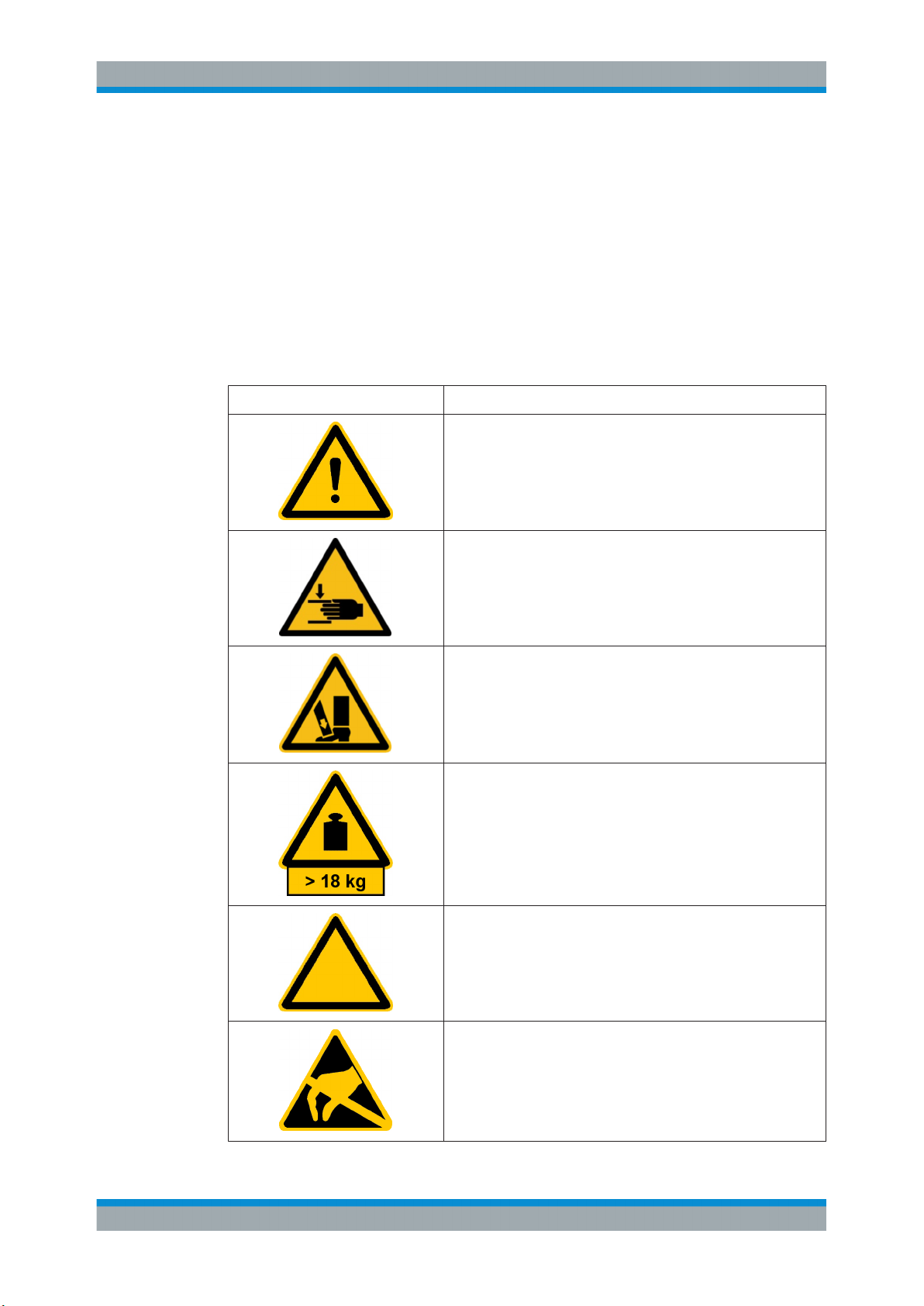
Symbol Explanation
WARNING!
Indicates the risk of personal injury
To prevent personal injury, observe and follow safety instructions.
WARNING!
Indicates the risk of contusion of hand and fingers
To prevent contusion of the hand and fingers, follow the safety
instructions on how to operate the chamber.
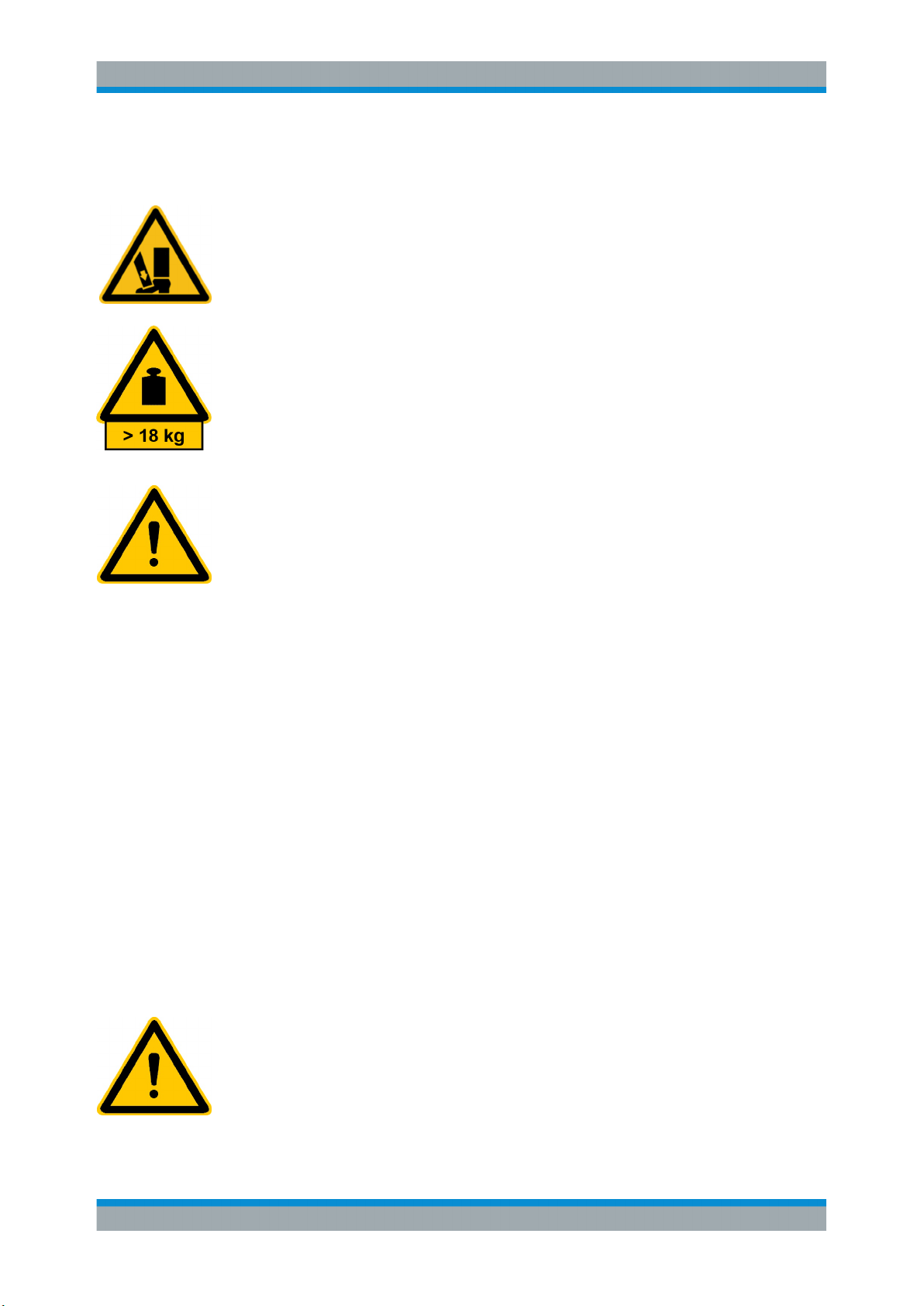
WARNING!
Indicates the risk of toes / foot injury due to the heavy chamber and
its door.
To prevent toes or foot injury, follow the safety instructions for transport, unpacking and operation.
CAUTION!
Indicates a weight for heavy units >18 kg
To prevent personal injury, follow the safety instructions for transport, unpacking and operation.
NOTICE
Indicates a risk of malfunction
To achieve correct measurement results, observe the operating
instructions.
NOTICE
Indicates the risk of ESD
In order to prevent electrostatic discharge effects, follow the instructions in "Risk of damaging electrical parts" on page 27. Electrostatic sensitive devices require special care.
8User Manual 1506.9481.08 ─ 04
Page 9

R&S®TS7121x
2.2 Intended Use
Specific Safety Instructions
Authorized Operators
NOTICE
Indicates a risk of damage to the installation
To prevent damage to the Shielded RF Test Box or incorrect measurement results, follow the safety instructions.
Ground (protective earth, PE)
The Shielded RF Test Box is intended for radiation testing of electronic devices. Any
other use is regarded as improper use, which can result in safety hazards and damage. Always use the appropriate, specially manufactured cables and adapters for testing the device under test (DUT).
The Shielded RF Test Box is only permitted to be operated within the permissible
parameter ranges as specified in the data sheet (included in the delivery).
The Shielded RF Test Box is intended for industrial use and must be installed, operated, configured, maintained and repaired by trained personnel, only.
2.3 Authorized Operators
An authorized operator is a person who, as a result of special instruction or training
courses, is familiar with handling the Shielded RF Test Box. The operator must have
read and understood the operating instructions. Only trained personnel with the proper
instruction is permitted to carry out work on the Shielded RF Test Box.
The duties of personnel responsible for the following must be clearly defined:
●
Installation
●
Operation
●
Configuration
●
Maintenance
●
Repair
When instructing personnel, you must lay particular emphasis on possible hazards and
on the safety procedures. Proper use also includes the observance of this manual and
the observance of the inspection and maintenance requirements (see Chapter 6,
"Maintenance", on page 31).
9User Manual 1506.9481.08 ─ 04
Page 10
R&S®TS7121x
2.4 Safety Instructions for Unpacking and Transport
Specific Safety Instructions
Safety Instructions for Setup
Risk of contusion due to heavy moving parts
For transportation, the Shielded RF Test Box is originally contained in a special transport protection packaging. After unpacking, there is no additional protection to prevent
opening of the drawer (door). Especially when the chamber is tilted, the door can slide
open unintentionally. This movement can cause personal injuries, especially contusion.
Risk of injury due to heavy weight
Handling the heavy Shielded RF Test Box (e.g. lifting or transporting it) can result in
personal injury. To prevent this risk, handle the Shielded RF Test Box in an ergonomic
way. For example, carry it while maintaining a straight back and optionally with the help
of a second person. The R&S TS7121A (automatic version) must be mounted by fixing
it to a stable bench/support with 4 screws, see Chapter 5, "Setting Up the System",
on page 26.
Risk of injury due to unstable mounting
The support (bench, table, rack, or the like), onto which the Shielded RF Test Box is
mounted, must be sufficiently stable to bear the chamber's weight and to withstand the
door's momentum during operation. The screws that fix the mounting brackets to the
support, must hold a tight grip in the support's material. The screws must be strong
enough to withstand a dynamic long-term load. If the support or the screws fail, the
chamber can become destabilized and eventually tip out of place. This failing could
cause personal injuries, especially contusion.
2.5 Safety Instructions for Setup
Prerequisites for the installation of the Shielded RF Test Box:
●
Provide a stable mounting space (see weight and dimensions specified in the data
sheet).
Make sure that the location, in which the Shielded RF Test Box is mounted, leaves
sufficient room for the following: You must be able to open the door, to access the
door easily from all sides and to access all connectors and mounting brackets on
the front and rear side.
●
R&S TS7121A (automatic version): Provide external control circuitry (not included
in the delivery) that complies with the circuit diagram shown in Figure 4-3 and
includes a 24 VDC power supply.
●
R&S TS7121A (automatic version): Provide compressed air by a 6 mm push-in
tube that supplies 6 bar (max. 8 bar) of filtered, grease-free compressed air.
Risk of injury due to excess pressure of the compressed air supply
If the pressure in the compressed air supply system exceeds the limit of 0.8 MPa
(8 bar), the door operates under unspecified conditions (see data sheet). The excess
pressure can cause uncontrolled situations, which can lead to personal injuries, especially contusion.
10User Manual 1506.9481.08 ─ 04
Page 11
R&S®TS7121x
2.5.1 Positioning the Chamber
Specific Safety Instructions
Safety Instructions for Setup
To avoid this risk, only use the Shielded RF Test Box in a site that features an air preparation unit or service unit. This unit must limit the pressure of the compressed air supply to 6 bar (max. 8 bar) and provide filtered, grease-free compressed air.
Risk of injury due to heavy moving parts
Failure to fix the chamber properly before the first usage leads to a risk of injury as
described in Chapter 2.6, "Safety Instructions for Operation", on page 12. To avoid
this risk, mount the chamber securely, as described below.
Fix the Shielded RF Test Box in place by screwing the four mounting holes (Figure 4-2)
on the front and rear side of the chamber to a stable bench or support.
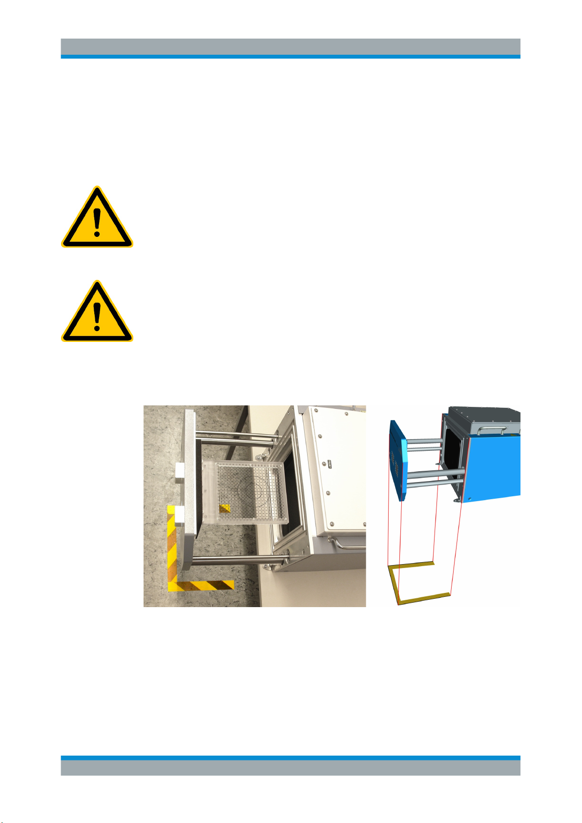
Risk of collision and contusion within the danger zone
The opening door can collide with a person or an obstacle that is present in a specific
area in front of the chamber. This area, which is utilized by the opened door, must be
regarded as a danger zone of the Shielded RF Test Box.
To avoid the risk of damage or personal injury, especially due to collision and contusion, everything and everybody must stay out of the danger zone.
Mark the danger zone on the ground below the chamber's opened door, as shown in
Figure 2-1.
Figure 2-1: Danger zone of the door marked on the ground, as illustrated on the right (here shown
with a similar RF test box)
If you must remove the box from this location, for example to open the top cover,
observe the Safety Instructions for Unpacking and Transport. Only operate the door
while the Shielded RF Test Box is securely mounted to a stable support.
11User Manual 1506.9481.08 ─ 04
Page 12
R&S®TS7121x
2.6 Safety Instructions for Operation
Specific Safety Instructions
Safety Instructions for Operation
Risk of injury due to pneumatic door operation
The heavy Shielded RF Test Box features a solid metal door that can be automatically
opened and closed. Automatic operation is required for short measurement cycle times
and is realized with the R&S TS7121A (automatic) version. The heavy weight is
required to achieve high levels of electromagnetic shielding. This combination of automation and massive construction implies some inevitable risk of injury for the operators. The risk of contusion when closing the Shielded RF Test Box occurs at the movable lever mechanism (R&S TS7121M), at the movable pressure cylinder, and between
the Shielded RF Test Box door part and the Shielded RF Test Box. To avoid potential
risk of contusion, keep away from the gap between the door and the chamber, when
the door is about to be closed.
Risk of injury due to remote operation
If the chamber's door is closed by a remote operator from a distant position, a local
operator near by the chamber can be injured. Especially the operator's hands can suffer contusion while placing a DUT into the chamber or taking a DUT out of the chamber. To avoid this risk, make sure that the remote operator has a good view of the
Shielded RF Test Box and observes it while operating the door.
Risk of contusion due to heavy moving parts
If the chamber comes into an unstable position, this situation can lead to personal
injury, especially contusion. Without the pneumatic system keeping the door closed,
such a tilting movement could even contribute to a faster opening. To avoid this risk,
make sure that the chamber is securely mounted to a stable support.
Risk of injury due to high pressure
Setting up the Shielded RF Test Box can lead to a risk of personal injury due to the
pneumatic system. To avoid this risk, respect the following:
●
Before initially connecting the chamber to the compressed air supply, switch off the
compressed air supply.
●
When connecting the chamber to the compressed air supply, be aware of the possibility of a sudden opening or closing of the chamber door.
●
Observe all local and national regulations applicable for pneumatic systems.
●
Any work on the pneumatic system is a service task, which must only be carried
out by properly qualified service personnel.
Risk of injury due to excess pressure of the compressed air supply
If the pressure in the compressed air supply system exceeds the limit of 0.8 MPa
(8 bar), the door operates under unspecified conditions (see data sheet). The excess
pressure can cause uncontrolled situations, which can lead to personal injuries, especially contusion.
To avoid this risk, only use the Shielded RF Test Box in a site that features a suitable
air preparation unit or service unit. This unit must limit the pressure of the compressed
air supply to 6 bar (max. 8 bar) and provide filtered, grease-free compressed air.
12User Manual 1506.9481.08 ─ 04
Page 13
R&S®TS7121x
Specific Safety Instructions
Safety Instructions for Maintenance
Risk of injury in case of malfunction
If the Shielded RF Test Box is operated without being in proper working order, malfunctions could lead to unpredictable events.
To avoid risks in the event of a malfunction:
●
immediately take the chamber out of service,
●
report the malfunction to the responsible department,
●
eliminate any faults before work is continued.
Risk of mechanical damage due to high pressure
Malfunction of the pneumatic system could cause mechanical damage. Make sure that
during operation, the air pressure is within its specifications of 6 bar (max. 8 bar). For
staying within these specifications, it is recommended to use an air pressure control.
Other safety instructions
Persons not trained in handling the Shielded RF Test Box must be kept out of the
range of operation, as they do not know about all potential hazards of injury. Observe
internal instructions and ensure that the area of operation is always clear and clean. All
areas for handling, service and maintenance must be kept easy to access.
2.7 Safety Instructions for Maintenance
Risk of injury in case of uninformed maintenance
Servicing the pneumatic system of the R&S TS7121A can lead to a risk of personal
injury.
To avoid this risk, respect the following:
●
Work on the pneumatic system must be carried out by properly qualified service
personnel, only.
●
Before working on the pneumatic system, terminate the supply of compressed air
and verify that the system is de-pressurized.
●
Observe all regulations applicable for work on pneumatic systems.
Risk of damaging electrical or mechanical parts
Malfunction of the pneumatic system could cause mechanical damage. Make sure that
during operation, the air pressure is within its specifications of 6 bar (max. 8 bar). To
stay within these specifications, we highly recommend using an air pressure control.
Protect surrounding area
When maintenance tasks are carried out on the Shielded RF Test Box, the surrounding
area must be protected by appropriate measures. This protection includes:
●
Erecting barriers
●
Putting up warning signs
●
Other similar measures
13User Manual 1506.9481.08 ─ 04
Page 14

R&S®TS7121x
3 System Overview and Usage
3.1 Important User Information
System Overview and Usage
Functions of the Shielded RF Test Box
● Important User Information..................................................................................... 14
● Functions of the Shielded RF Test Box................................................................... 14
● Usage of the Shielded RF Test Box........................................................................ 16
The Shielded RF Test Box is controlled via the program in the test system that is connected.
Risk of injury from insufficient qualification of personnel
Only trained persons are permitted to operate the Shielded RF Test Box.
Before switching on the Shielded RF Test Box the first time, the operator must read
and understand Chapter 2, "Specific Safety Instructions", on page 7.
3.2 Functions of the Shielded RF Test Box
The Shielded RF Test Box is built for the testing of electronic devices, especially the
radiation test. The door in front of the Shielded RF Test Box is used for insertion of the
DUT (device under test). The cover of the Shielded RF Test Box is for service issues.
All interfaces are at the back of the Shielded RF Test Box.
The Shielded RF Test Box is available in two base models that differ mainly in width
and a manual and an automatic version of each model.
14User Manual 1506.9481.08 ─ 04
Page 15

R&S®TS7121x
System Overview and Usage
Functions of the Shielded RF Test Box
Figure 3-1: Overview of the different models of the R&S TS712x family
Manual Shielded RF Test Box R&S TS7121M and R&S TS7123M
You can use the manual versions completely without air pressure or electric power
supply.
Table 3-1: R&S
TS7121M and R&S TS7123M
Automatic Shielded RF Test Box R&S TS7121A and R&S TS7123A
The automatic version has a pneumatic cylinder for opening and closing the door and a
rear 25-pin D-Sub connector. This connector is used for controlling the pneumatic cylinder and for checking the open and close sensors. The Shielded RF Test Box can be
15User Manual 1506.9481.08 ─ 04
Page 16

R&S®TS7121x
System Overview and Usage
Usage of the Shielded RF Test Box
controlled by an operator using a switching unit or is controlled by software. No operator is needed during production.
The automatic version of the Shielded RF Test Box contains a larger base plate for fixing.
Table 3-2: R&S TS7121A and R&S TS7123A
3.3 Usage of the Shielded RF Test Box
The screened Shielded RF Test Box is an adaptation platform for testing devices with
radio interfaces, e.g.:
●
Mobile telephones
●
PDAs
●
Radio keys
●
WLAN, Bluetooth modules, etc.
The Shielded RF Test Box can be used in production, service, for repairs and in other
applications. In the Shielded RF Test Box, the assemblies to be tested are adapted to
suit the specific device. Thus, control and measured signals can reach the DUT from
the controlling test system.
The Shielded RF Test Box can be controlled using the following test systems:
●
Rohde & Schwarz RF test system R&S TS7810
●
Rohde & Schwarz test platform for mobile phone production R&S TS 7180
●
Any test system using a USB interface or TTL signals
16User Manual 1506.9481.08 ─ 04
Page 17

R&S®TS7121x
4 System Hardware Description
4.1 Hardware Overview
4.1.1 Front Tour
System Hardware Description
Hardware Overview
● Hardware Overview.................................................................................................17
● Accessories.............................................................................................................21
This chapter describes all components used in the Shielded RF Test Box.
● Front Tour................................................................................................................17
● Rear Tour................................................................................................................ 18
● 25-Pin D-Sub Connector for Pneumatic Control and Sensor Reading................... 20
● 25 and 9-Pin D-Sub Feedthrough Connectors........................................................21
Figure 4-1: Front view of the opened Shielded RF Test Box
1 = Door for DUT change
2 = Cover for service issues
3 = Closing mechanism for cover (manual and semiautomatic versions only)
4 = Customer-specific DUT holder
5 = Plate with guiding pins for DUT holder
6 = Pneumatic cylinder
7 = Door guide rail
17User Manual 1506.9481.08 ─ 04
Page 18

R&S®TS7121x
4.1.2 Rear Tour
System Hardware Description
Hardware Overview
The front door (1) of the Shielded RF Test Box is used for insertion of the DUT. The
DUT can be fixed on the plate (5) with guiding pins for DUT holder. Two pneumatic cylinders (6, one on each side) open and close the door, with guide rails (7) providing
additional stability. The cover (2) of the Shielded RF Test Box is fixed by two clamping
fixtures (3). It can be removed for service issues.
Figure 4-2: Back view of the Shielded RF Test Box
1 = Exchangeable connector plate
2 = RF 1 N-connector (X1, reserved for GSM antenna coupler)
3 = RF 2 N-connector (X2, spare)
4 = RF 3 N-connector (X3, spare)
5 = RF 4 N-connector (X4, reserved for Bluetooth antenna coupler)
6 = 25 and 9-pin D-Sub connectors (X20 and X21) with RF filter (3 dB cut-off at 3 MHz) as a feedthrough
for power supply, RS-232-C, etc.
7 = 25-pin D-Sub connector (X10) for power supply, pneumatic control and sensor reading
8 = Air pressure connector for pneumatic supply (see chapter 5.2.1)
9 = One of four mounting holes on the front and rear side of the chamber
GND = Grounding contact
18User Manual 1506.9481.08 ─ 04
Page 19

R&S®TS7121x
System Hardware Description
Hardware Overview
On the rear side (also shown in Figure 5-1), the Shielded RF Test Box has components
for the installation, including a grounding contact (GND). The automatic version Shielded RF Test BoxA also has an air pressure connector (8) and a 25-pin D-Sub connector (7). This connector is used for controlling the automatic opening/closing, reading
out the current state and input for the 24V DC power supply.
For the pneumatic installation of the automatic Shielded RF Test Box, refer to Chap-
ter 5.2.1, "Connecting the R&S TS7121A to Compressed Air Supply", on page 27.
The items labeled with an asterisk (*) in Figure 4-2 are only available with the automatic version R&S TS7121A. In the manual version R&S TS7121M, these items do not
exist.
You can adapt the exchangeable connector plate (1) on the rear panel for your special
needs. In our example (6), it is equipped with a 25-pin and 9-pin D-Sub connector.
The four RF N-connectors, labeled (2) to (5) in Figure 4-2, allow feeding RF signals
into the Shielded RF Test Box towards internal antennas or directly towards the DUT.
Risk of reduced shielding effectiveness
If you install additional feedthroughs into the exchangeable connector plate, consider
the components’ shielding effectiveness. If you install the feedthroughs incorrectly, the
shielding effectiveness can deteriorate dramatically. Rohde & Schwarz assumes no liability for these modifications.
19User Manual 1506.9481.08 ─ 04
Page 20

R&S®TS7121x
4.1.3 25-Pin D-Sub Connector for Pneumatic Control and Sensor Read-
System Hardware Description
Hardware Overview
ing
Figure 4-3: Circuit diagram of automatic open/close mechanism
Figure 4-4: Internal circuit diagram pneumatic sensor
Operating voltage 24 VDC
Maximum current 5 mA to 20 mA
Voltage drop 2.4 V
20User Manual 1506.9481.08 ─ 04
Page 21

R&S®TS7121x
4.1.4 25 and 9-Pin D-Sub Feedthrough Connectors
System Hardware Description
Accessories
The connectors X20 (25 pin) and X21 (9 pin) are fully customer-specific. These feedthroughs are typically used for power supply, RS-232-C, IO signals, etc.
The feedthrough connectors have RF filters with a 3 dB cut-off at 3 MHz.
Figure 4-5: Typical insertion loss of filter connector
For more technical data, refer to the data sheet.
4.2 Accessories
This chapter describes the accessories for the Shielded RF Test Box.
● GSM / CDMA2000 / WCDMA / BT Antenna Coupler..............................................21
● Bluetooth Antenna Coupler R&S TS-F2x-B2.......................................................... 23
● Antenna Coupler ISM R&S TS-F2x-I4.................................................................... 23
● Elevated Cover R&S TS-F21EC1........................................................................... 24
● USB Feedthrough Filter R&S TS-F21FU2.............................................................. 25
4.2.1 GSM / CDMA2000 / WCDMA / BT Antenna Coupler
An RF connection to the DUT is made via the DUT's antenna and the universal
antenna coupler. This coupler is installed in the lower and side part of the Shielded RF
21User Manual 1506.9481.08 ─ 04
Page 22

R&S®TS7121x
System Hardware Description
Accessories
Test Box. Connect the universal antenna coupler directly to an RF SMA connector on
the rear panel of the Shielded RF Test Box.
Figure 4-6: GSM antenna coupler for R&S TS7121and R&S TS7123
1 = GSM 900 / CDMA 2000 DCN coupler
2 = GSM 1800 / GSM 1900 / UMTS / CDMA2000 PCS coupler
Type Designation Order No.
R&S TS-F2x-G GSM, CDMA2000 and WCDMA
antenna coupler with RF cable
without absorber
R&S TS-F21AGB GSM, CDMA2000, WCDMA and
Bluetooth antenna coupler with
absorber for R&S TS7121
1506.9017.04
1506.9000.02
22User Manual 1506.9481.08 ─ 04
Page 23

R&S®TS7121x
4.2.2 Bluetooth Antenna Coupler R&S TS-F2x-B2
System Hardware Description
Accessories
Table 4-1: Bluetooth antenna coupler for R&S TS7121
VSWR < 2.5 (at 2.4 GHz to 2.5 GHz)
Type Designation Order No.
R&S TS-F2x-B2 Bluetooth antenna with mounting
material and RF cable (without
absorber)
4.2.3 Antenna Coupler ISM R&S TS-F2x-I4
The ISM antenna coupler R&S TS-F2x-14 is used for the following frequencies in the
industrial, scientific and medical (ISM) RF bands:
●
315 MHz to 316 MHz
●
433 MHz to 434 MHz
●
865 MHz to 870 MHz
●
902 MHz to 928 MHz
1506.9046.02
23User Manual 1506.9481.08 ─ 04
Page 24

R&S®TS7121x
System Hardware Description
Accessories
Figure 4-7: Antenna coupler ISM R&S TS-F2x-I4 for TS712x
Type Designation Order No.
R&S TS-F2x-I4 Wideband antenna for ISM
- Antenna module
- RF cable (SMA-SMA)
4.2.4 Elevated Cover R&S TS-F21EC1
Elevated covers are available for both Shielded RF Test Box models, allowing the integration of additional test equipment.
1506.9030.02
Figure 4-8: Elevated cover for R&S
TS7121
Dimensions (W x H x D): 155 x 185 x 400 mm
Additional height for internal applications1): 150 mm
24User Manual 1506.9481.08 ─ 04
Page 25

R&S®TS7121x
4.2.5 USB Feedthrough Filter R&S TS-F21FU2
System Hardware Description
1)
with absorber
Type Designation Order No.
R&S TS-F21EC1 Elevated cover for R&S TS7121 1506.9052.02
R&S TS-F21AB1 Absorber for R&S TS-F21EC1 1506.9130.02
The USB feedthrough filter for R&S TS7121 consists of:
●
Filtered feedthrough for USB 1.1 and USB 2.0 data rates
●
Exchangeable R&S TS7121 connector plate for
– D-Sub feedthrough (9-pin and 25-pin connectors)
– USB feedthrough
Accessories
Figure 4-9: Exchangeable connector plate with USB filter connector (top right)
Type Designation Order No.
R&S TS-F21FU2 Feedthrough filter USB 2.0 for
R&S TS7121
1506.9181.02
25User Manual 1506.9481.08 ─ 04
Page 26

R&S®TS7121x
5 Setting Up the System
5.1 Unpacking and Checking the Equipment
Setting Up the System
Unpacking and Checking the Equipment
Prerequisites for the installation of the Shielded RF Test Box (only R&S TS7121A):
●
Stable mounting space (see weight and dimensions in the data sheet)
●
Power supply (24 V DC voltage)
●
Compressed air supply: 6 mm push-in tube, providing 6 bar of grease-free compressed air
Check the equipment for completeness using the delivery note and the accessory lists
of the delivered items. Check the Shielded RF Test Box for any damage. If there is
damage, immediately contact the carrier who delivered it.
Retain the original packaging material. If the Shielded RF Test Box needs to be transported or shipped later, you can use the material to protect the equipment.
Risk of damage during transportation and shipment
Insufficient protection against mechanical and electrostatic effects during transportation
and shipment can damage the Shielded RF Test Box.
●
When shipping the Shielded RF Test Box, we recommend using the original packaging material. If it is not available, use sufficient padding to prevent the chamber
from moving around inside the box.
●
Secure the chamber to prevent any movement and other mechanical effects during
transportation.
●
Always provide sufficient mechanical and electrostatic protection.
26User Manual 1506.9481.08 ─ 04
Page 27

R&S®TS7121x
5.2 Installation
Setting Up the System
Installation
Risk of damaging electrical parts
To secure testing devices and equipment against static charging or discharging, provide appropriate ESD protection for the area surrounding the Shielded RF Test Box.
Operators must observe all applicable ESD regulations.
To install the Shielded RF Test Box, perform the following steps (for interfaces and connections, see Figure 4-2):
1. Fix the Shielded RF Test Box in place by screwing the chamber to a stable bench
or support.
This step is only available for the R&S TS7121A (automatic version).
2. Ground the Shielded RF Test Box using the electrical grounding contact on rear
side.
3. Connect the Shielded RF Test Box via the 25-pin D-Sub connector to an external
control unit. This connector is also the input for the 24 VDC supply.
This step is only available for the R&S TS7121A (automatic version).
4. Connect the Shielded RF Test Box via the air pressure connector to a compressed
air supply, as described in chapter 5.2.1.
This step is only available for the R&S TS7121A (automatic version).
5. Connect the interfaces according to the requirements of your application.
5.2.1 Connecting the R&S TS7121A to Compressed Air Supply
This chapter describes how to connect the R&S TS7121A (automatic version with
pneumatic system) to a compressed air supply, and how to disconnect it. Note that
connecting a pneumatic system is not possible with the manual version
R&S TS7121M.
27User Manual 1506.9481.08 ─ 04
Page 28

R&S®TS7121x
Setting Up the System
Installation
Figure 5-1: Lower rear panel of the R&S TS7121A
1 = 25-pin D-Sub connector (X10) for power supply, pneumatic control and sensor reading
2 = Grounding contact
3 = Air pressure connector for pneumatic supply with 6 mm plastic tubing
4 = Movable ring for releasing the pressure tube
To connect the R&S TS7121A to a compressed air supply, proceed as follows:
1. Ground the chamber using the electrical grounding connection on the rear side
(2 in Figure 5-1).
2. Switch off the compressed air supply.
3. Insert the 6 mm tube of the compressed air supply into the chamber's air pressure
connector (3 in Figure 5-1), as shown in the left-hand side (1) of Figure 5-2.
4. Switch on the compressed air supply. (If you have multiple chambers, switch on the
compressed air supply after you have connected all chambers.)
5. Make sure to provide an air pressure of 6 bar. Do not exceed the maximum input
pressure of 8 bar.
To disconnect the R&S TS7121A from the compressed air supply, proceed as follows:
1. Switch off the compressed air supply.
2. Push the gray plastic ring (4 in Figure 5-1) at the end of the connector towards the
chamber, away from the tube, as shown in the right-hand side (2) of Figure 5-2.
(That figure shows a similar connector with a blue instead of a gray ring.)
3. While keeping the gray ring pushed in, gently pull the 6 mm tube out of the connec-
tor.
4. By some means, which is not within the scope of this description, make sure to
close the open pressure tube, before you switch on the compressed air supply.
28User Manual 1506.9481.08 ─ 04
Page 29

R&S®TS7121x
Setting Up the System
Adjustments of the R&S TS7121A
Figure 5-2: Assembly and disassembly of the air pressure connector (left in both pictures) and a
1 = To insert the 6 mm tube into the connector, push the tube all the way in. For best results, we recommend
a straight cut rather than an angled cut end of the tube.
2 = To disconnect the 6 mm tube from the connector, first switch off the compressed air supply. Then gently
pull the tube out of the adapter while firmly pushing in the blue (or gray) ring in the opposite direction, as
indicated by the blue arrows.
6 mm tube (right in both pictures)
5.3 Adjustments of the R&S TS7121A
On the right-hand side of the R&S TS7121A (automatic version), there are two control
screws for adjusting the door speed (see Figure 4-2). These screws limit the pressure
and hence control the flow rate of the compressed air.
Figure 5-3: Side view of the Shielded RF Test Box
1 = Speed adjustment screw for the door closing movement
2 = Speed adjustment screw for the door opening movement
29User Manual 1506.9481.08 ─ 04
Page 30

R&S®TS7121x
Setting Up the System
Adjustments of the R&S TS7121A
Figure 5-4: Speed adjustment screw for the pneumatic door operation
Do not exceed the maximum input air pressure of 8 bar.
30User Manual 1506.9481.08 ─ 04
Page 31

R&S®TS7121x
6 Maintenance
6.1 Important User Instructions
Maintenance
General
● Important User Instructions.....................................................................................31
● General................................................................................................................... 31
● Maintenance Intervals.............................................................................................32
● Greasing Moving Parts of the Handle..................................................................... 33
● Cleaning the Shielded RF Test Box........................................................................ 33
Risk of injury due to an operative system
Make sure that the test system is switched off before you perform maintenance tasks.
Service and inspection tasks must be performed by trained personnel, only.
When work is carried out on the Shielded RF Test Box, the surrounding area must be
protected by appropriate measures. These measures typically include:
●
Erecting barriers
●
Putting up warning signs
●
Other similar measures
6.2 General
To retain the functional readiness and long lifetime of the Shielded RF Test Box, maintenance and inspection tasks must be performed carefully at the intervals specified.
To prevent damage to the environment, carefully dispose all waste and expendables
produced during the use of the Shielded RF Test Box.
31User Manual 1506.9481.08 ─ 04
Page 32

R&S®TS7121x
6.3 Maintenance Intervals
Maintenance
Maintenance Intervals
The following table shows the various service, maintenance and inspection tasks that
are to be carried out in the stated intervals on the Shielded RF Test Box. The intervals
are valid for a single work shift corresponding to about 160 hours per month. Calibration of test instruments must be carried out by a certified laboratory (for example
Rohde & Schwarz calibration service).
Table 6-1: Scheduled maintenance
Maintenance interval Maintenance tasks
Daily Complete Shielded RF Test Box
Weekly Cables, connectors and absorber checking
Weekly Safety precautions
Depending on amount of soiling Complete Shielded RF Test Box
Half year or 10 000 cycles Grease moving parts of the handle
Every 100 000 cycles
1)
●
Check the Shielded RF Test Box for damage
and proper function
●
Check the handle for proper function (manual
version)
●
Check the door's gasket for soiling, damage
and wear
●
Check connecting cables and connectors for
damage and correct cable connections
●
Check the absorber material on the inside of
the door and around the chamber's door opening for damage or wear
●
Check the safety precautions described in
Chapter 2, "Specific Safety Instructions",
on page 7
●
Clean the R&S TS7121, if it is soiled
Gasket
●
Change of the door gasket is required every
100 000 cycles or at least every 6 months. This
exchange ensures a continuous quality of the
RF attenuation
Contact the Rohde & Schwarz service.
1 year Test instruments
1)
The attainable shielding effectiveness of the RF gaskets depends on how long the
●
A calibration of the test instruments is required
every year
Contact the Rohde & Schwarz calibration service
gaskets remain in a relaxed state. The door gaskets were tested in a 2:1 time ratio of
opened versus closed state. A longer period of relaxation results in even higher shielding effectiveness than specified or a longer life. This improvement can be achieved, for
example, by leaving the door open between production periods. With reverse ratios,
maintenance is necessary at shorter intervals.
32User Manual 1506.9481.08 ─ 04
Page 33

R&S®TS7121x
6.4 Greasing Moving Parts of the Handle
Maintenance
Cleaning the Shielded RF Test Box
Figure 6-1: Additional points for greasing (manual version)
Do not remove the screws of the handles (2), they are attached with glue.
6.5 Cleaning the Shielded RF Test Box
6.5.1 Cleaning the Chamber
Risk of damaging electrical or mechanical parts
Do not apply liquid cleaning agents such as contact spray to electrical interfaces.
33User Manual 1506.9481.08 ─ 04
Page 34

R&S®TS7121x
6.5.2 Cleaning the Gasket Contact Area
Maintenance
Cleaning the Shielded RF Test Box
You can clean all areas inside the Shielded RF Test Box by using a vacuum cleaner.
For a constant level of high radiation shielding efficiency, the gasket must be cleaned.
The following equipment and materials are recommended for cleaning:
●
Soft, lint-free cleaning cloth
●
Soft brush
●
Alcohol
The following cleaning steps must be performed.
1. Carefully use the soft brush in a dry condition to pre-clean the gasket.
2. Clean the chromated aluminum contact area of the gasket using soft, lint-free
cleaning cloths and alcohol.
34User Manual 1506.9481.08 ─ 04
Page 35

R&S®TS7121x
7 Spare Parts Lists R&S TS7121
Spare Parts Lists R&S TS7121
Fig. Quantity Unit Description Order number
-- 1.0 Piece Air supply connector bushing 1504.3505.00
-- 1.0 Piece Air supply connector plug 1504.3511.00
-- 1.0 Piece 125 grams absorber glue 0016.8741.00
1 1.0 Piece Absorber set 1504.3728.00
4 2.0 Piece Clamping fixture 1504.3370.00
5 4.0 Piece N-connector N-male/SMA-male 0614.5111.00
6 4.0 Piece Gasket f. N connector 1504.3305.00
7a 1.0 Piece 25-pin D-Sub filter connector 3 MHz cut-off 1504.3711.00
7b 1.0 Piece 9-pin D-Sub filter connector 3 MHz cut-off 1506.6247.00
8a 1.0 Piece Gender changer 25-pin. male/female 1504.3270.00
8b 1.0 Piece Gender changer 9-pin. male/female 1506.6253.00
9a 1.0 Piece Exchangeable connector plate 1507.0388.00
9b 1.0 Piece Gasket f. exchangeable connector plate 1507.0407.00
10 2.0 Piece DUT holder centering 1504.3157.00
11 1.0 Piece Support plate (door) for DUT holder plate 1504.3070.00
12 1.0 Piece Rear plate 1504.3092.00
13 2.0 Piece Centering during door closing 1504.3086.00
14 2.0 Piece One-way restrictor 1504.3492.00
16 1.0 Piece Pneumatic cylinder 1519.1761.00
17 1.0 Piece Sound absorber 1/8 1504.3528.00
18 1.2 Meter Pneumatic line I4/A6 1504.3611.00
19 1.0 Piece Magnetic valve 1504.3486.00
20 2.0 Piece Sound absorber M5 1504.3534.00
21 4.0 Piece Pneumatic plug connection / wound 1504.3605.00
22 1.0 Piece Wiring cable for pneumatic valve 1504.3992.00
24 2.0 Piece Pneumatic sensor 1519.1910.00
25 1.0 Piece Pneumatic plug connection / straight 1504.3563.00
26 2.0 Piece Axle ø25 1504.3063.00
27 1.0 Piece Gasket 4X8X600 (door) 1504.3840.00
28 4.0 Piece Linear roller bearing / self-regulating 1504.3463.00
35User Manual 1506.9481.08 ─ 04
Page 36

R&S®TS7121x
Spare Parts Lists R&S TS7121
Fig. Quantity Unit Description Order number
29 1.0 Piece Gasket 5X5X1100 (cap) 1504.3857.00
30 1.0 Piece Washer 1504.3034.00
31 1.0 Piece O-Ring 30x2 1506.6299.00
32 1.0 Piece Bolt (door) for handle 1504.3934.00
33a 1.0 Piece Left part of handle 1504.3886.00
33b 1.0 Piece Right part of handle 1504.3870.00
36User Manual 1506.9481.08 ─ 04
Page 37

R&S®TS7121x
Spare Parts Lists R&S TS7121
37User Manual 1506.9481.08 ─ 04
Page 38

R&S®TS7121x
Spare Parts Lists R&S TS7121
38User Manual 1506.9481.08 ─ 04
Page 39

R&S®TS7121x
Spare Parts Lists R&S TS7121
39User Manual 1506.9481.08 ─ 04
Page 40

R&S®TS7121x
Spare Parts Lists R&S TS7121
40User Manual 1506.9481.08 ─ 04
Page 41

R&S®TS7121x
Glossary: List of Frequently Used Terms and Abbreviations
Glossary: List of Frequently Used Terms
and Abbreviations
B
Bluetooth: A wireless mobile technology standard for radio communication over short
distances of up to 60 m, using RF frequencies from 2.4 to 2.485 GHz
D
D-Sub: Electrical D-subminiature connector, surrounded by a D-shaped metal support
DUT: Device under test
E
ESD: Electrostatic discharge
G
Gasket: A mechanical seal
P
PDA: Personal digital assistant
R
Radio key: Car key with remote control features
RF: Radio frequency, electromagnetic oscillation in the frequency range of around
3 kHz to 300 GHz
S
SMA connector: SubMiniature coaxial RF connector, version A (standard)
U
USB: Universal Serial Bus, industrial connector standard
V
VSWR: Voltage standing wave ratio, ratio of the maximum standing wave amplitude
over the minimum standing wave amplitude
W
Wi-Fi: A wireless internet connectivity technology for electronic devices (synonymical
with WLAN)
WLAN: Wireless local area network (synonymical with Wi-Fi)
41User Manual 1506.9481.08 ─ 04
Page 42

R&S®TS7121x
Index
Index
A
Antenna coupler
Bluetooth, R&S TS-F2x-B2 ......................................... 23
ISM R&S TS-F2x-14 ................................................... 23
Universal, R&S TS-F2x-G ........................................... 21
Universal, R&S TS-F23A-G ........................................ 21
C
CD-ROM ............................................................................. 5
Cleaning ............................................................................ 33
D
D-Sub control connector (25 pin) ...................................... 18
D-Sub feedthrough (25 and 9 pin) ..................................... 21
Danger zone ...................................................................... 11
E
Elevated cover R&S TS-F21EC1 ...................................... 24
ESD ................................................................................... 27
F
Feedthrough for USB, R&S TS-F21FU2 ........................... 25
Feedthrough, D-Sub (25 and 9 pin) .................................. 21
H
Hazards
Door ...................................................................... 12, 13
Pneumatics ........................................................... 12, 13
Remote operation ....................................................... 12
Weight ......................................................................... 12
S
Safety
Door ...................................................................... 12, 13
Hazards ................................................................ 10, 12
Instruction ............................................................... 9, 12
Pneumatics ................................................................. 13
Regulations ................................................................... 7
Setup .......................................................................... 10
Symbols ........................................................................ 8
Spare parts ........................................................................ 35
U
USB feedthrough, R&S TS-F21FU2 ................................. 25
M
Maintenance intervals ....................................................... 32
Malfunction ........................................................................ 12
O
Operators
Authorization ................................................................. 9
Instruction ..................................................................... 9
P
Pneumatic adjustment ....................................................... 29
R
R&S TS 7180 .................................................................... 16
R&S TS 7810 .................................................................... 16
R&S TS7121A
automatic opening and closing ................................... 14
R&S TS7121M
manual opening and closing ....................................... 14
Risks ............................................................. 7, 8, 10, 12, 13
42User Manual 1506.9481.08 ─ 04
 Loading...