

Page 1

®
R&S
TSMA
Autonomous Mobile
Network Scanner
Getting Started
(;ÛÆ42)
1177560402
Version 10
Getting Started
Page 2

This manual describes the following R&S®TSMA models:
●
R&S®TSMA (1514.6520.20)
© 2019 Rohde & Schwarz GmbH & Co. KG
Mühldorfstr. 15, 81671 München, Germany
Phone: +49 89 41 29 - 0
Fax: +49 89 41 29 12 164
Email: [email protected]
Internet: www.rohde-schwarz.com
Subject to change – Data without tolerance limits is not binding.
R&S® is a registered trademark of Rohde & Schwarz GmbH & Co. KG.
Trade names are trademarks of the owners.
1177.5604.02 | Version 10 | R&S®TSMA
Throughout this manual, products from Rohde & Schwarz are indicated without the ® symbol , e.g.
R&S®TSMA is indicated as R&S TSMA.
Page 3

R&S®TSMA
Contents
1 Safety Information................................................................. 5
2 Documentation Overview......................................................6
2.1 Getting Started Manual.........................................................................6
2.2 User Manuals and Help........................................................................ 6
2.3 Basic Safety Instructions..................................................................... 6
2.4 Data Sheets and Brochures................................................................. 6
2.5 Release Notes and Open Source Acknowledgment (OSA)...............7
3 Key Features.......................................................................... 8
Contents
4 Preparing for Use...................................................................9
4.1 Unpacking the Instrument..................................................................10
4.2 Connecting External Devices.............................................................11
4.3 Connecting Power Supply................................................................. 14
4.3.1 Connecting to a Vehicle DC Power Supply...........................................14
4.3.2 Connecting an AC Power Supply..........................................................14
4.3.3 Connecting the R&S TSMA-BP Battery Pack Unit................................14
4.4 Connecting an Additional R&S TSME for MIMO Support................20
4.4.1 MIMO 2x2 Upgrade Kit......................................................................... 21
4.4.2 Mounting R&S TSME ...........................................................................22
4.5 Connecting Test Mobile Phones........................................................24
4.6 R&S TSMA Driver Update...................................................................25
4.6.1 Installation MIMO Extension ................................................................ 25
4.6.2 Installation ROMES/NESTOR Mobile Device Drivers...........................28
5 Instrument Tour................................................................... 30
5.1 Front Panel.......................................................................................... 30
3Getting Started 1177.5604.02 ─ 10
Page 4

R&S®TSMA
5.2 Rear Panel........................................................................................... 30
5.3 Status LEDs.........................................................................................34
5.3.1 PWR, SCAN, STATE.............................................................................34
5.3.2 SCAN LINK........................................................................................... 36
Contents
6 Configuring the R&S TSMA................................................ 37
6.1 Accessing the R&S TSMA..................................................................37
6.1.1 Start the R&S TSMA Web-GUI............................................................. 37
6.1.2 Establish a Remote Desktop Connection............................................. 38
6.2 Changing Password of R&S TSMA................................................... 40
6.3 Measurement Setup............................................................................42
6.4 Measurement Modes.......................................................................... 43
6.4.1 Remote ViCom Server Mode................................................................ 43
6.4.2 QualiPoc Mode..................................................................................... 44
6.4.3 NESTOR and NESTOR Probe Mode....................................................47
6.4.4 ROMES Mode.......................................................................................49
6.4.5 PC Mode............................................................................................... 50
6.4.6 Scanner Only Mode.............................................................................. 50
6.5 Power Settings.................................................................................... 51
Index..................................................................................... 52
4Getting Started 1177.5604.02 ─ 10
Page 5

R&S®TSMA
Safety Information
1 Safety Information
The product documentation helps you use the R&S TSMA safely and efficiently.
Follow the instructions provided here and in the printed "Basic Safety Instructions". Keep the product documentation nearby and offer it to other users.
Intended use
The R&S TSMA is intended for the development, production and verification of
electronic components and devices in industrial, administrative, and laboratory
environments. Use the R&S TSMA only for its designated purpose. Observe the
operating conditions and performance limits stated in the data sheet.
Where do I find safety information?
Safety information is part of the product documentation. It warns you about the
potential dangers and gives instructions how to prevent personal injuries or damage caused by dangerous situations. Safety information is provided as follows:
●
The printed "Basic Safety Instructions" provide safety information in many languages and are delivered with the R&S TSMA.
●
Throughout the documentation, safety instructions are provided when you
need to take care during setup or operation.
5Getting Started 1177.5604.02 ─ 10
Page 6

R&S®TSMA
Documentation Overview
Data Sheets and Brochures
2 Documentation Overview
This section provides an overview of the R&S TSMA user documentation. Unless
specified otherwise, you find the documents on the R&S TSMA product page at:
www.rohde-schwarz.com/manual/tsmx
2.1 Getting Started Manual
Introduces the R&S TSMA and describes how to set up and start working with the
product. Includes basic operations, typical measurement examples, and general
information, e.g. safety instructions, etc. A printed version is delivered with the
instrument.
2.2 User Manuals and Help
Contains the description of all instrument modes and functions. Includes the contents of the getting started manual .
2.3 Basic Safety Instructions
Contains safety instructions, operating conditions and further important information. The printed document is delivered with the instrument.
2.4 Data Sheets and Brochures
The data sheet contains the technical specifications of the R&S TSMA. It also
lists the firmware applications and their order numbers, and optional accessories.
The brochure provides an overview of the instrument and deals with the specific
characteristics.
See www.rohde-schwarz.com/brochure-datasheet/tsmx
6Getting Started 1177.5604.02 ─ 10
Page 7

R&S®TSMA
Release Notes and Open Source Acknowledgment (OSA)
Documentation Overview
2.5 Release Notes and Open Source Acknowledgment (OSA)
The release notes list new features, improvements and known issues of the current firmware version, and describe the firmware installation.
The open source acknowledgment document provides verbatim license texts of
the used open source software.
See www.rohde-schwarz.com/firmware/tsmx
7Getting Started 1177.5604.02 ─ 10
Page 8

R&S®TSMA
Key Features
3 Key Features
As in-building traffic in cellular networks grows, there is an increased need for
indoor measurements. While traditional drive test systems consist of a laptop with
test mobile phones and scanners, there are also walk-test solutions that use tablets and smartphones.
The R&S TSMA enhances such solutions, providing the user with accurate insight
into the RF environment.
The R&S TSMA combines the technology of the R&S TSME ultra-compact drive
test scanner with a high-performance Intel processor. The scanner can run PCbased drive test software, and smartphones can be connected via USB. The
scanner measures up to eight technologies simultaneously in the 350 MHz to
4400 MHz wireless communications bands. It can be combined with an R&S
TSME to perform LTE MIMO measurements.
●
User-definable input frequency range from 350 MHz to 4400 MHz
●
RF and signal processing path with a bandwidth of 20 MHz
●
Parallel measurement of all technologies in all bands (up to eight technologies
simultaneously)
●
Integrated Intel PC with Microsoft® Windows operating system which allows
to install any drive test software supporting the R&S TSMA (e.g R&S ROMES)
●
Open remote ViCom interface in order to integrate into Windows and Androidbased software tools.
●
Automatic detection of active channels in a specified band (Automatic Channel Detection (ViCom only), R&S TSMA-K40, Order No. 1524.6339.02 or R&S
ROMES4ACD )
●
Analysis of the DL allocations of the strongest eNodeBs during measurement
(LTE Downlink Allocation Analyzer, R&S TSMA-K31, Order No. 1524.6322.02)
8Getting Started 1177.5604.02 ─ 10
Page 9

R&S®TSMA
4 Preparing for Use
Risk of injury and instrument damage
The instrument must be used in an appropriate manner to prevent electric
shock, fire, personal injury, or damage.
●
Do not open the instrument casing.
●
Read and observe the "Basic Safety Instructions" delivered as a printed
brochure with the instrument.
In addition, read and observe the safety instructions in the following sections. Notice that the data sheet may specify additional operating conditions.
Preparing for Use
Risk of instrument damage during operation
An unsuitable operating site or test setup can cause damage to the instrument and to connected devices. Ensure the following operating conditions
before you switch on the instrument:
●
The instrument is dry and shows no sign of condensation.
●
The instrument is positioned as described in the following sections.
●
Signal levels at the input connectors are all within the specified ranges.
EMI Suppression
Electromagnetic interference (EMI) may affect the measurement results.
To suppress generated electromagnetic interference (EMI):
●
Use suitable shielded cables of high quality. For example, use doubleshielded RF and LAN cables.
●
Always terminate open cable ends.
●
Note the EMC classification in the data sheet.
9Getting Started 1177.5604.02 ─ 10
Page 10

R&S®TSMA
Unpacking the Instrument
Preparing for Use
4.1 Unpacking the Instrument
The following section describes how to setup the instrument.
Risk of instrument damage due to inappropriate operating conditions
Specific operating conditions are required to ensure accurate measurements and to avoid damage to the instrument. Observe the information on
appropriate operating conditions provided in the basic safety instructions
and the instrument's data sheet.
Check the equipment for completeness using the delivery note and the accessory
lists for the various items. Check the instrument for any damage. If there is damage, immediately contact the carrier who delivered the instrument. Make sure not
to discard the box and packing material.
Packing material
Retain the original packing material. If the instrument needs to be transported or shipped later, you can use the material to protect the control elements and connectors.
Accessory list
The following items are included with shipment of the R&S TSMA:
●
SCAN Link interconnection cable (SCAN <-> SCAN)
●
12 V DC power supply cable with a cigarette lighter connector
●
Wide range RF paddle antenna (700 MHz to 2600 MHz)
●
Active GPS patch antenna
●
Two stub antennas for WLAN/Bluetooth
®
10Getting Started 1177.5604.02 ─ 10
Page 11

R&S®TSMA
Preparing for Use
Connecting External Devices
Figure 4-1: Scope of R&S TSMA Delivery
1 = SCAN Link interconnection cable
2 = Car Adapter cable
3 = RF Antenna
4 = GPS Antenna
5 = WiFi/Bluetooth Antennas
4.2 Connecting External Devices
The following external devices must be connected before connecting the power
supply.
To select the correct connectors, see the following picture.
11Getting Started 1177.5604.02 ─ 10
Page 12

R&S®TSMA
Figure 4-2: R&S TSMA - Rear Panel
1 = POWER ON/OFF
2 = STATUS LEDs
3 = AUX Connector
4 = SCAN (scanner port from scanner)
5 = SCAN (scanner port to embedded PC)
6 = USB 2.0 (2x)
7 = USB 3.0 (2x)
8 = mini HDMI
9 = MINI Display Port
10 = LAN Connector CPU
11 = DC IN Connector
12 = RF IN Connector
13 = GPS Antenna Connector
14 =
Antenna 1 Connector (Bluetooth® / WLAN MIMO)
15 = Antenna 2 Connector (WLAN)
16 = RESTORE
Preparing for Use
Connecting External Devices
1. Connect the SCAN ports of scanner and PC unit of the R&S TSMA.
Figure 4-3: Connection between scanner unit and internal PC unit
1 = SCAN Link connector (CPU port)
2 = SCAN Link connector (Scanner Port)
3 = SCAN Link interconnection cable
12Getting Started 1177.5604.02 ─ 10
Page 13

R&S®TSMA
Preparing for Use
Connecting External Devices
Note: Use only the LAN interconnection cable (R&S No. 5016.1890.00) for
connecting the SCAN ports.
2. Connect the RF antenna to the RF IN connector.
3. Connect the GPS antenna to the GPS ANT port.
4. Connect the accessory WLAN / Bluetooth stub antennas to ANT1 and ANT 2.
5. Connect mouse and keyboard to the USB 2.0 ports and a monitor to the
appropriate monitor port (mini HDMI or MINI Display port) if you want to use
local operation. (optional)
If necessary, following display port adapters can be used:
● Display Port Adapter to DVI/HDMI, R&S TSPC-DPDH (R&S No.
3592.4060.02)
Figure 4-4: Display Port Adapter to DVI/HDMI
● Display Port Adapter to VGA, R&S TSPC-DPVG (R&S No. 3592.4076.02)
Display Port Adapter to VGA
6. Connect a LAN cable to the LAN port if you want to use the R&S TSMA via
Remote Desktop or as distributed system. (optional)
7. Connect external devices/storage devices and test mobile phones to USB
2.0/USB 3.0 ports.
Note: The length of the connected USB cables should not exceed 3 m.
13Getting Started 1177.5604.02 ─ 10
Page 14

R&S®TSMA
Connecting Power Supply
Preparing for Use
4.3 Connecting Power Supply
This section describes how to connect the R&S TSMA to a power supply unit.
4.3.1 Connecting to a Vehicle DC Power Supply
Use the accessory DC cable with cigarette lighter adapter to power the R&S
TSMA from the vehicle power supply. Connect the 7-pin connector to DC IN.
For DC Supply Only
The R&S TSMA is to be used with a 12 V vehicle power supply only.
DC-based lab networks are not allowed to be used for power supply!
4.3.2 Connecting an AC Power Supply
To operate the R&S TSMA with an AC power supply, connect the DC IN connector with the AC power supply (R&S TSMA-Z1, R&S No. 1523.8450.02).
Use only the R&S TSMA-Z1, R&S No. 1523.8450.02 as AC power supply.
Figure 4-5: TSMA-Z1 AC Power Supply
4.3.3 Connecting the R&S TSMA-BP Battery Pack Unit
Alternatively, it is possible to power the R&S TSMA via the R&S TSMA-BP Battery Pack Unit.
To use the R&S TSMA with the battery pack, the following steps must be performed.
1. Insert the batteries into the R&S TSMA.
14Getting Started 1177.5604.02 ─ 10
Page 15

R&S®TSMA
Preparing for Use
Connecting Power Supply
Note: The R&S TSMA may be used only with closed battery cover.
Note: Make sure, that the batteries are inserted in the correct orientation.
Figure 4-6: R&S TSMA - Battery Orientation
1 = Battery insert orientation
2. Attach the R&S TSMA base unit with the bottom side (see Figure 4-8) on top
of the R&S TSMA-BP (see Figure 4-7).
Figure 4-7: R&S TSMA-BP
1 = Connectors for R&S TSMA base unit
15Getting Started 1177.5604.02 ─ 10
Page 16

R&S®TSMA
Figure 4-8: R&S TSMA Base Unit (bottom side)
1 = Connectors for R&S TSMA-BP
Preparing for Use
Connecting Power Supply
3. Move the R&S TSMA base unit to the front side (2) until the connectors are
locked.
Figure 4-9: Connected R&S TSMA Base Unit and R&S TSMA-BP
1 = Vertical attachment of R&S TSMA base unit (bottom) with R&S TSMA BP (top)
2 = Move T&S TSMA base unit to the front side
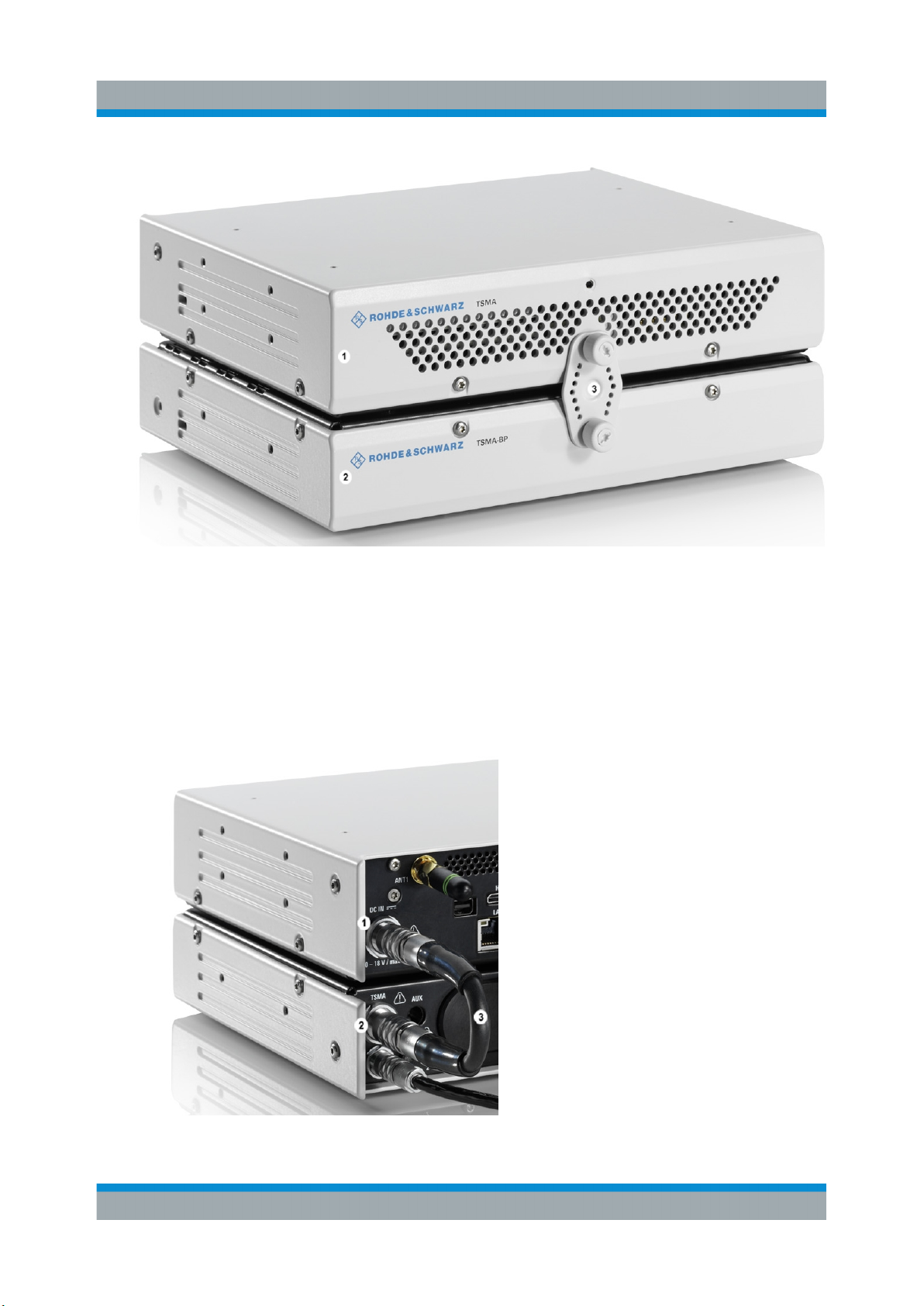
4. Lock the interconnection using the lock (3).
16Getting Started 1177.5604.02 ─ 10
Page 17
R&S®TSMA
Preparing for Use
Connecting Power Supply
Figure 4-10: Connection of R&S TSMA with R&S TSMA
1 = R&S TSMA Base Unit
2 = R&S TSMA
3 = Lock (front side)
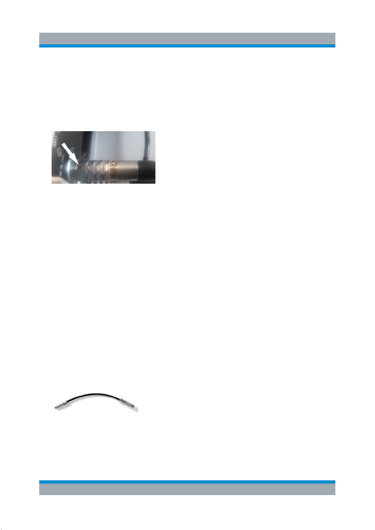
5. Via the cable (3), you have to connect the DC IN connector on the R&S TSMA
(1) with the TSMA connector (7 pins) on the R&S TSMA-BP (2).
Figure 4-11: Cabling of R&S TSMA with R&S TSMA
17Getting Started 1177.5604.02 ─ 10
Page 18
R&S®TSMA
Preparing for Use
Connecting Power Supply
1 = DC IN Connector of R&S TSMA Base Unit
2 = TSMA Connector R&S TSMA-BP
3 = Interconnection Cable (R&S TSMA Base Unit <-> R&S TSMA-BP)
Note: The interconnection cable (3) is included in the delivery package of the
R&S TSMA-BP.
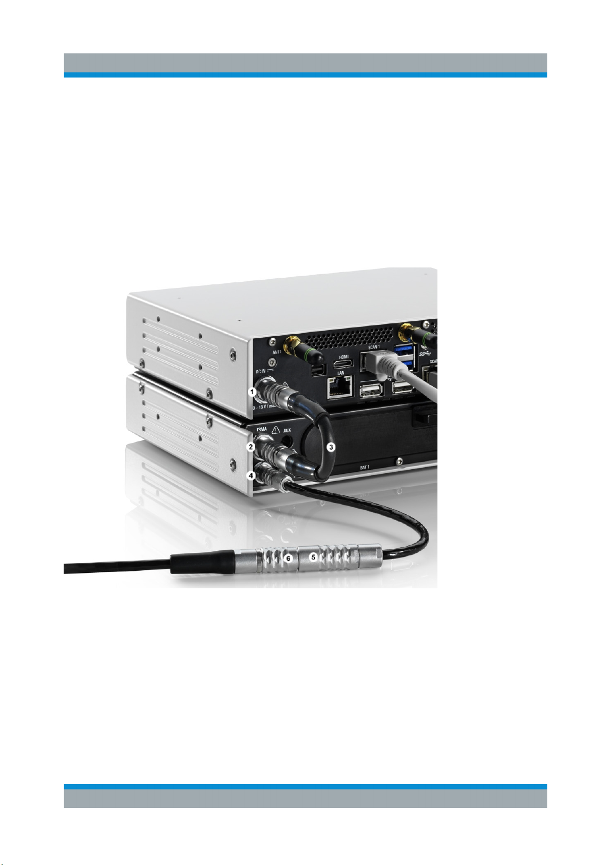
The cable plugs are marked at both sides with a red spot.
Figure 4-12: Cable
Connected at the DC IN (1) of the R&S TSMA, this red spot must face
upwards, at the TSMA connector (2) of the R&S TSMA-BP it must face downwards.
The boot behavior after connecting the R&S TSMA-BP Battery Pack Unit
(including charged batteries or connected to an external DC power supply)
with the R&S TSMA depends on the system settings on the R&S TSMA.
The R&S TSMA-BP Battery Pack Unit can be connected with an external power
supply. The following steps must be performed.
1. DC powered from a vehicle supply (see Figure 4-14)
Connect the DC IN connector (4) of the R&S TSMA-BP Battery Pack Unit with
the 7-pin plug cable (5) and connect the 4-pin socket with the accessory car
adapter cable of the R&S TSMA.
Note: The 7-pin to 4-pin adapter cable is a standard accessory of the R&S
TSMA-BP Battery Pack Unit
Figure 4-13: 7-pin to 4-pin adapter cable
2. AC powered
18Getting Started 1177.5604.02 ─ 10
Page 19
R&S®TSMA
Preparing for Use
Connecting Power Supply
Connect the DC IN connector (4) of the R&S TSMA-BP Battery Pack Unit with
the 7-pin to 4-pin adapter cable (5) and connect the 4-pin socket with AC
power supply (R&S TSMA-Z1, R&S No. 1523.8450.02).
If a valid DC input voltage is applied to DC IN of the R&S TSMA-BP, the R&S
TSMA is powered from this external DC supply and the batteries inside the
R&S TSMA-BP are charged.
If the external DC supply is not available the R&S TSMA is powered from the
batteries.
Figure 4-14: Connecting the R&S TSMA with an AC power supply
1 = DC IN connector R&S TSMA Base Unit
2 = TSMA connector R&S TSMA-BP Battery Pack Unit
3 = DC power interconnection cable (R&S TSMA Base Unit <-> R&S TSMA-BP Battery Pack
Unit)
4 = DC IN connector R&S TSMA-BP Battery Pack Unit
5 = Adapter cable (7-pin to 4-pin)
6 = DC IN (TSMA-Z1 resp. car adapter cable, standard accessory of R&S TSMA)
19Getting Started 1177.5604.02 ─ 10
Page 20
R&S®TSMA
Connecting an Additional R&S TSME for MIMO Support
Preparing for Use
4.4 Connecting an Additional R&S TSME for MIMO
Support
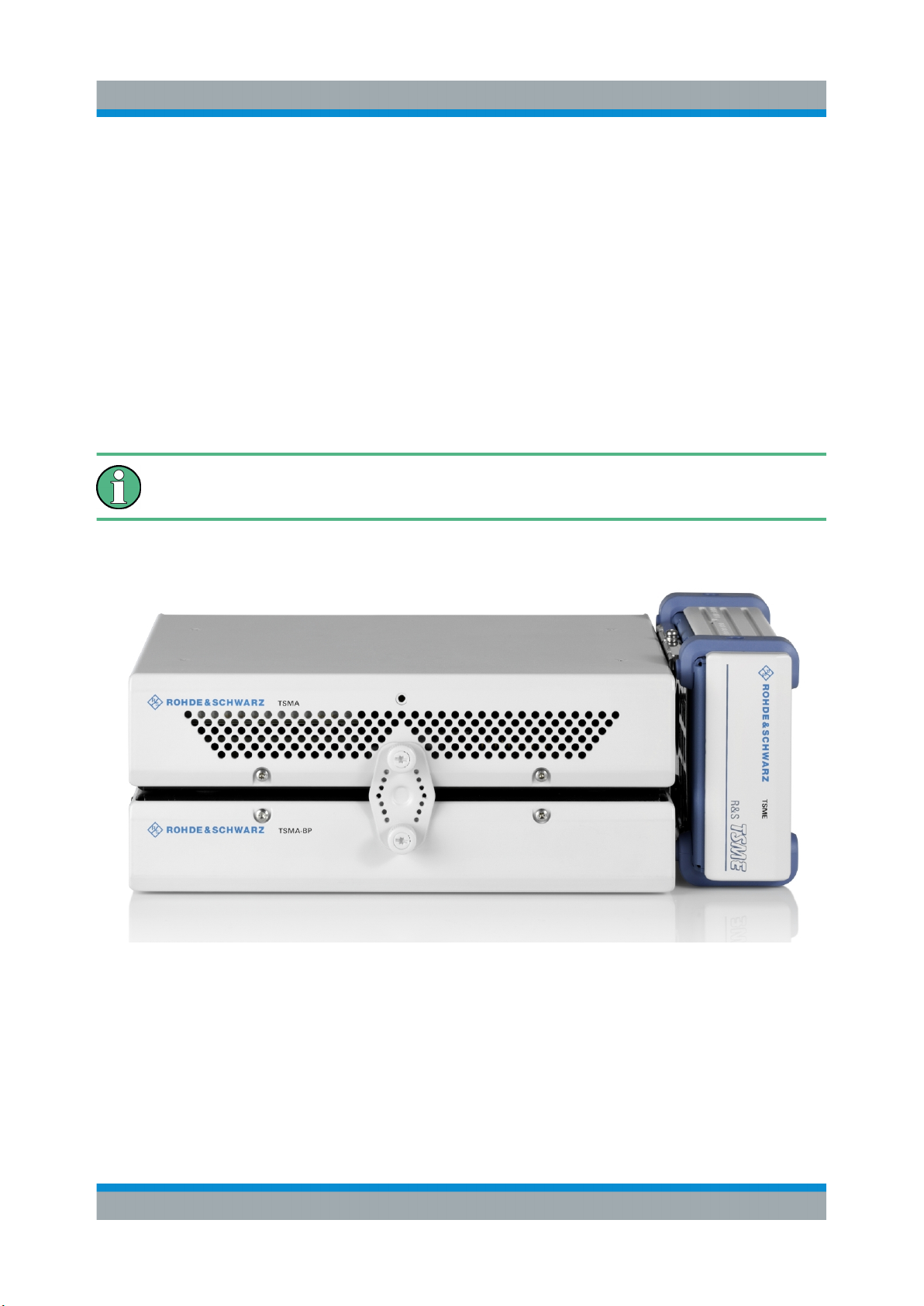
MIMO measurements with the R&S TSMA require to extend the device with one
R&S TSME.
To make this extension the following is needed:
●
MIMO 2x2 Upgrade Kit, R&S No. 15246439.02
●
R&S TSMA driver update software, TSMA_DriverUpdate_1.00.exe, which
can be downloaded from the Rohde & Schwarz web site.
The R&S TSMA driver update must be performed before connecting the
additional R&S TSME.
Figure 4-15: R&S TSMA with R&S TSMA-BP battery pack unit and mounted R&S TSME
(front side view)
20Getting Started 1177.5604.02 ─ 10
Page 21
R&S®TSMA
Preparing for Use
Connecting an Additional R&S TSME for MIMO Support
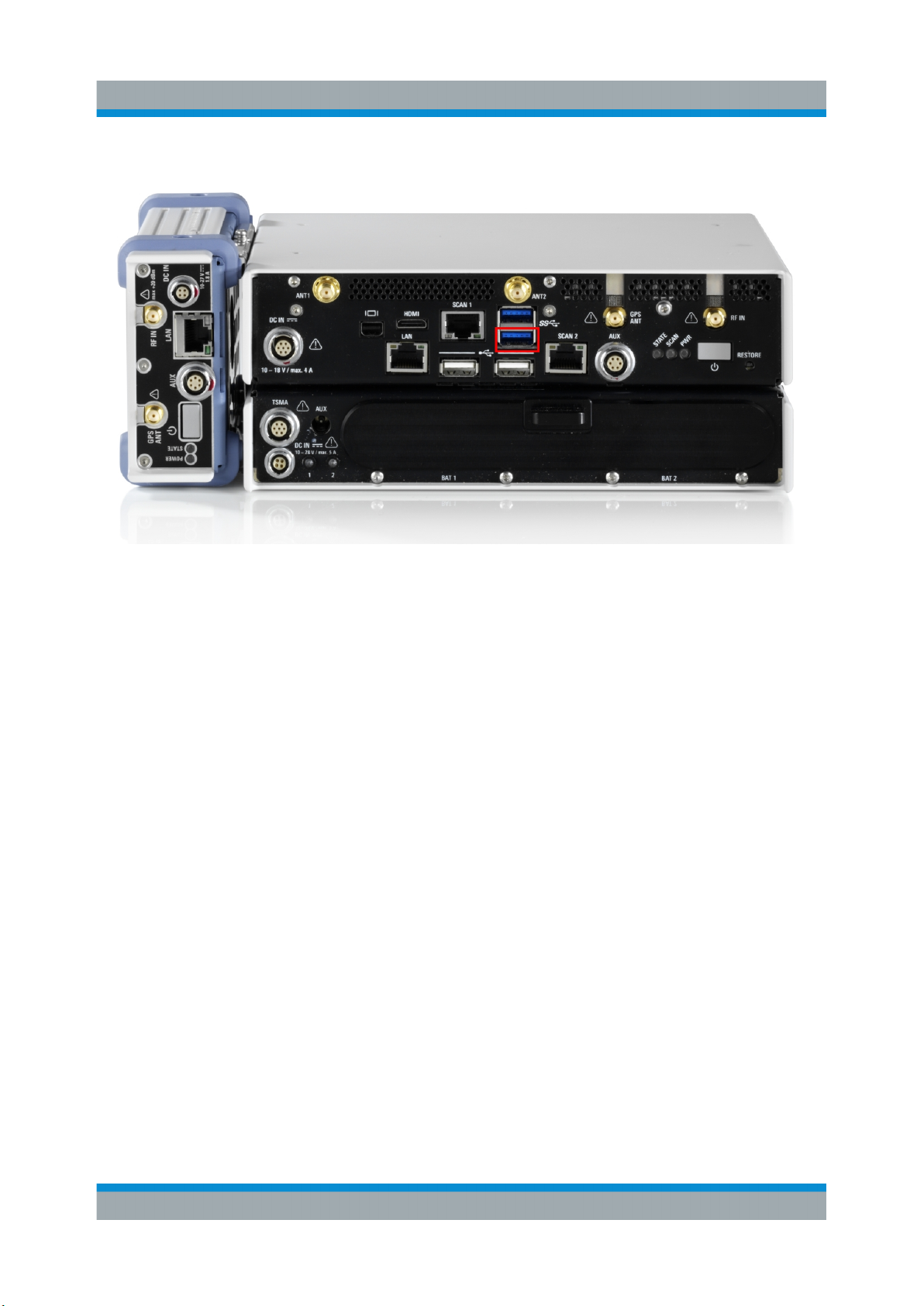
Figure 4-16: R&S TSMA with R&S TSMA-BP battery pack unit and mounted R&S TSME
(rear side view, emphasized is USB 3.0 lower port)
4.4.1 MIMO 2x2 Upgrade Kit
The upgrade kit includes the mechanical components to mount the R&S TSME
and the needed cables to connect the devices.
The following items are included in the MIMO 2x2 Upgrade Kit:
●
R&S TSPC-U2L USB 3.0 to LAN Adapter (3593.8430.02)
●
DC Cable TSMA-BP/TSME to connect R&S TSMA+BP with R&S TSME
(1523.8480.00)
●
SYNC Cable 2 TSME (1522.6577.00)
●
RJ45 Patch cable shielded CAT5E, 15 cm (5016.1890.00)
●
Holder TSMA+PB/TSME (1523.8415.00)
●
VS 7985/ISR-M3X5-A4-PA (3565.7210.009)
●
VS 7985/ISR-M2.5X5-A4-PA (1148.2617.00)
●
Installation Instruction R&S TSMA-ZM (1523.8438.00)
●
Documents folder (5001.8913.00)
21Getting Started 1177.5604.02 ─ 10
Page 22
R&S®TSMA
Preparing for Use
Connecting an Additional R&S TSME for MIMO Support
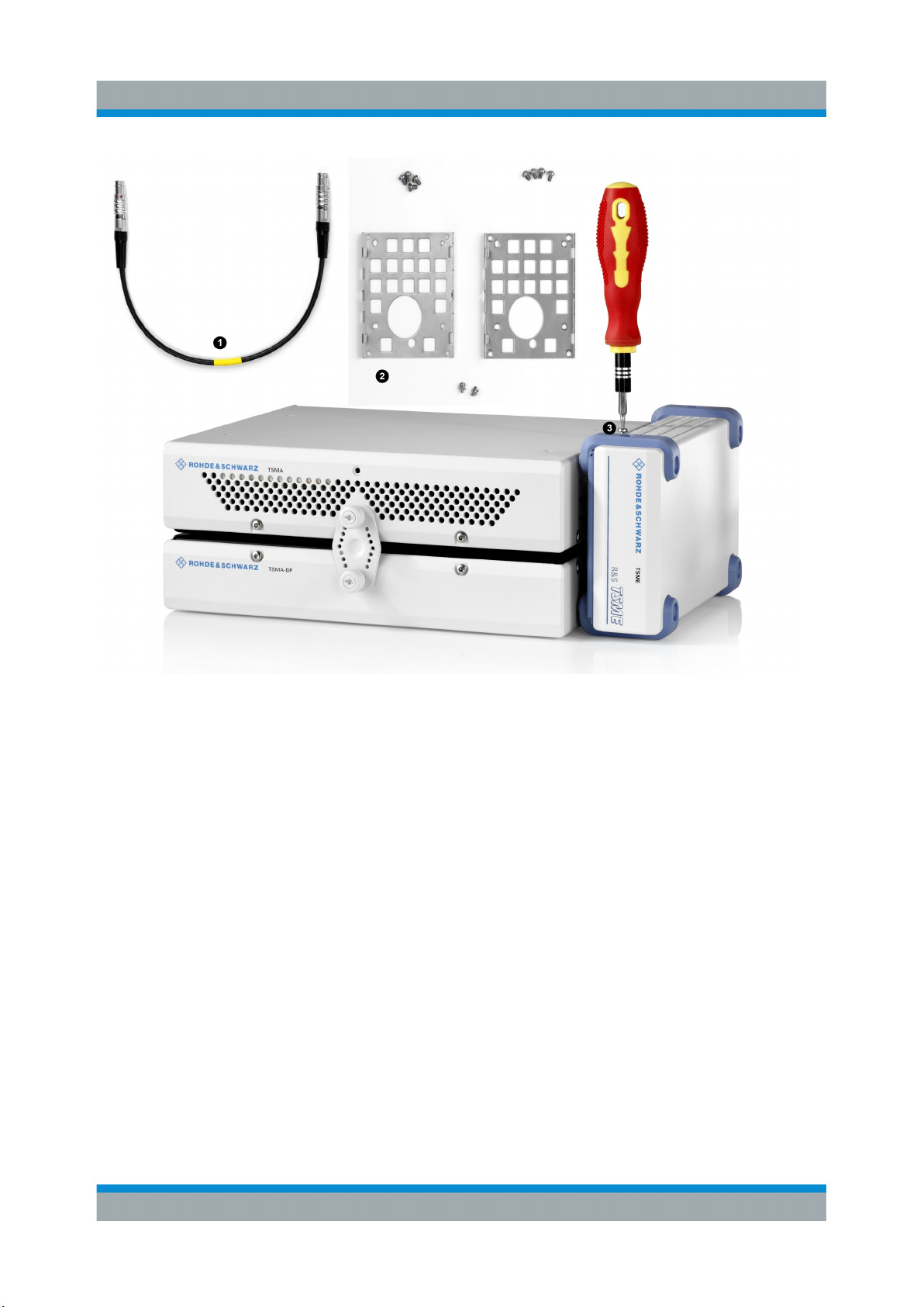
Figure 4-17: Some items of the upgrade kit
1 = SYNC cable for TSME
2 = Holders
3 = Turnlock fasteners
4.4.2 Mounting R&S TSME
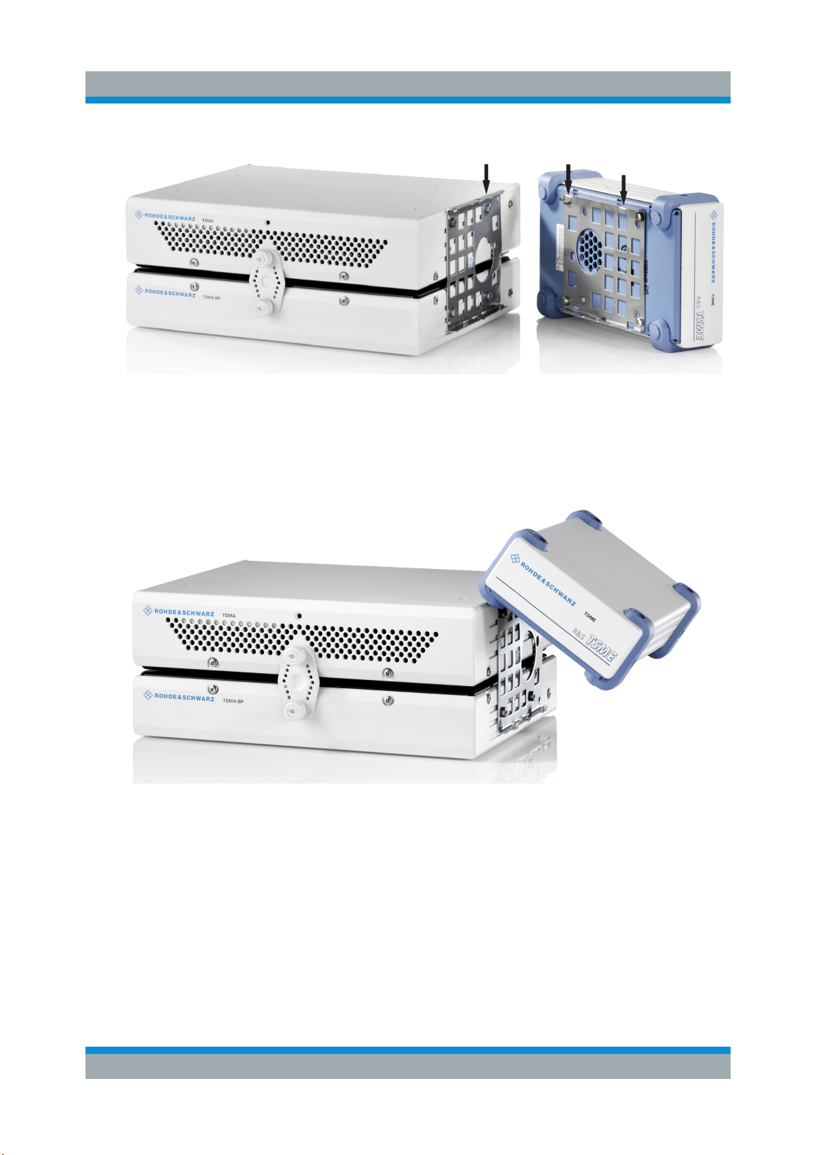
1. Screw the delivered holders to both devices. Note the differences when
screwing the holders.
22Getting Started 1177.5604.02 ─ 10
Page 23
R&S®TSMA
Preparing for Use
Connecting an Additional R&S TSME for MIMO Support
Figure 4-18: Holders screwed on the devices
2. Fasten the R&S TSME onto the R&S TSMA, attaching the R&S TSME as
shown in the following figure.
Figure 4-19: Mounting R&S TSME on R&S TSMA
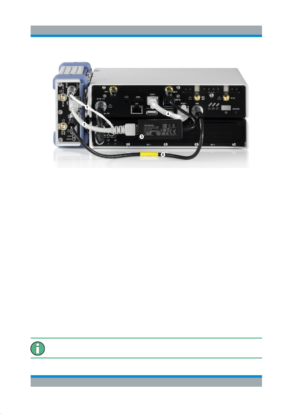
3. Connect devices using the cables including the MIMO 2x2 Upgrade Kit.
23Getting Started 1177.5604.02 ─ 10
Page 24
R&S®TSMA
Preparing for Use
Connecting Test Mobile Phones
Figure 4-20: Cabling of R&S TSME with R&S TSMA
1 = Connection TSME DC IN to TSMA-BP AUX port (DC Cable TSMA-BP/TSME)
2 = Connection TSME LAN port to R&S TSPC-2UL USB 3.0 to LAN Adapter (RJ45 Patch
cable shielded CAT5E)
3 = Connection lower USB 3.0 port of the R&S TSMA (the port marked in the figure display-
ing the rear side of the combination TSMA+BP/TSME) to R&S TSPC-2UL USB 3.0 to
LAN Adapter
4 = SCAN Link interconnection cable (not included in MIMO 2x2 Upgrade Kit)
5 = Connection TSME AUX port to TSMA AUX port (SYNC Cable 2 TSME)
4.5 Connecting Test Mobile Phones
To use the R&S TSMA with test mobile phones the following steps must be performed.
1. Install the driver package for the test mobile phones (see Chapter 4.6, "R&S
TSMA Driver Update", on page 25).
2. Connect the test mobile phones to the USB2.0 / USB3.0 ports.
The length of the connected USB cables should not exceed 3 m.
24Getting Started 1177.5604.02 ─ 10
Page 25
R&S®TSMA
R&S TSMA Driver Update
Preparing for Use
4.6 R&S TSMA Driver Update
●
The package "R&S TSMA ThinkPad USB LAN Setup 1.00" is required
to extend the R&S TSMA with an additional scanner LAN port for MIMO
LTE operation.
●
The packages "R&S TSMA Samsung Android USB Setup 1.00" and
"R&S TSMA Qualcomm Driver Setup 1.00" are the R&S ROMES/
NESTOR mobile device drivers, which are needed when a Samsung
test mobile phone is connected to the R&S TSMA.
The up-to-date instrument driver is available for download under https://
www.rohde-schwarz.com/driver/tsma/.
4.6.1 Installation MIMO Extension
For the installation of the driver update package "R&S TSMA ThinkPad
USB LAN Setup 1.00", the
R&S TSPC-U2L USB 3.0 to LAN Adapter (3593.8430.02) must be connected to the R&S TSMA.
1. Connect the LAN adapter to the R&S TSMA USB port.
2. Download the TSMA_DriverUpdate_1.00.exe file from the Rohde &
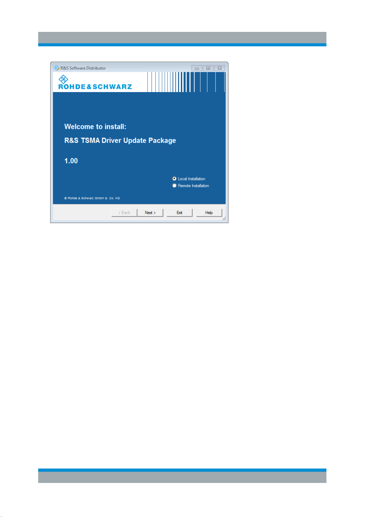
Schwarz web site and run it.
The "R&S Software Distribution" welcome to install page opens.
25Getting Started 1177.5604.02 ─ 10
Page 26
R&S®TSMA
Preparing for Use
R&S TSMA Driver Update
Figure 4-21: R&S Software Distributor opening page
3. Select "Local Installation" and click "Next".
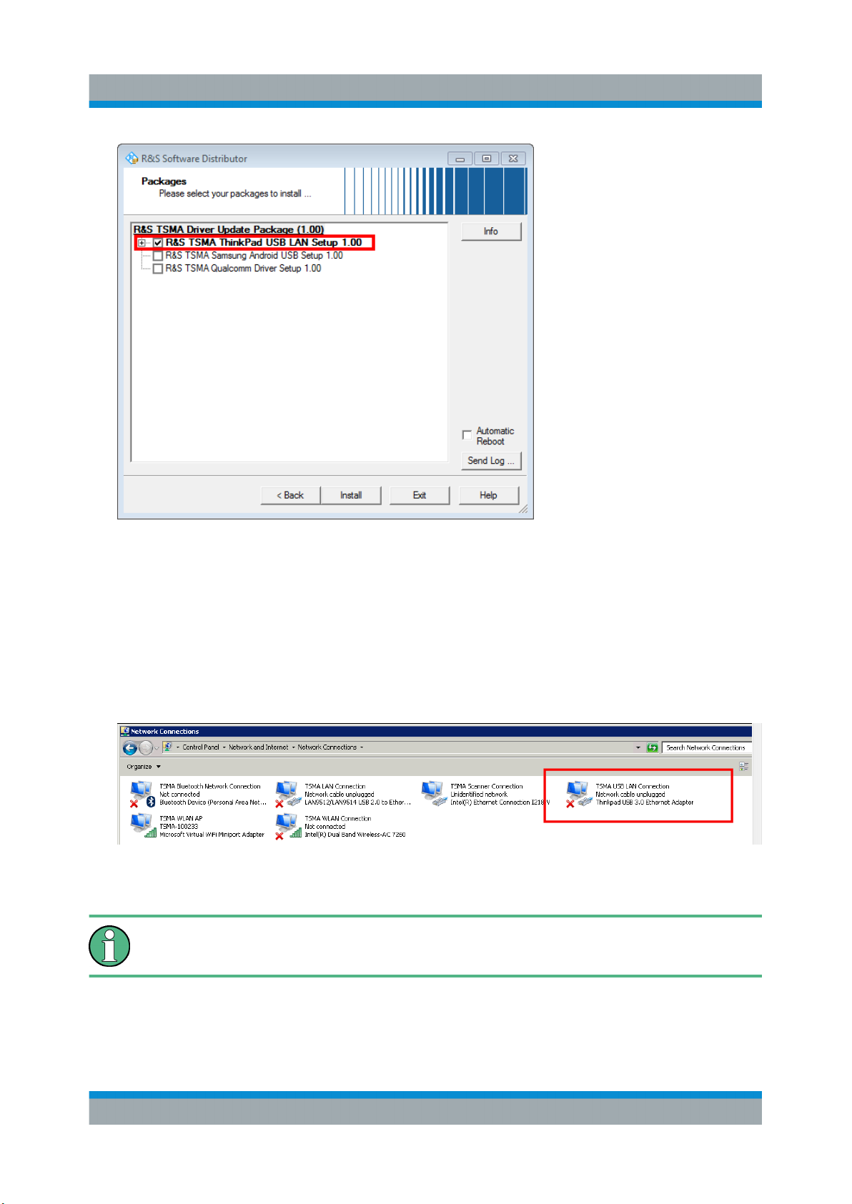
The opened page shows the contents of the "R&S TSMA Driver Update Package 1.00".
26Getting Started 1177.5604.02 ─ 10
Page 27
R&S®TSMA
Preparing for Use
R&S TSMA Driver Update
Figure 4-22: Contents of the R&S TSMA Driver Update Package
4. Select the "R&S TSMA ThinkPad USB LAN Setup 1.00" entry and click
"Install".
5. Close the installation.
The tool installs the required package and assigns the 192.168.2.1 IPv4
address to Ethernet adapter automatically.
Figure 4-23: Installed package
Make sure, that the IPv4 address 192.168.2.1 is not used by any other LAN
adapter.
The R&S TSME IP address has to be set to 192.168.2.x to support the R&S
TSMA MIMO measurements.
27Getting Started 1177.5604.02 ─ 10
Page 28
R&S®TSMA
R&S TSMA Driver Update
How to change the address: see "R&S TSME Ultra Compact Drive Test Scanner
User Manual" version 06, chapter 4.3.
Preparing for Use
4.6.2 Installation ROMES/NESTOR Mobile Device Drivers
Install the mobile device drivers before connecting a test mobile phone.
1. Download the TSMA_DriverUpdate_1.00.exe file from the Rohde &
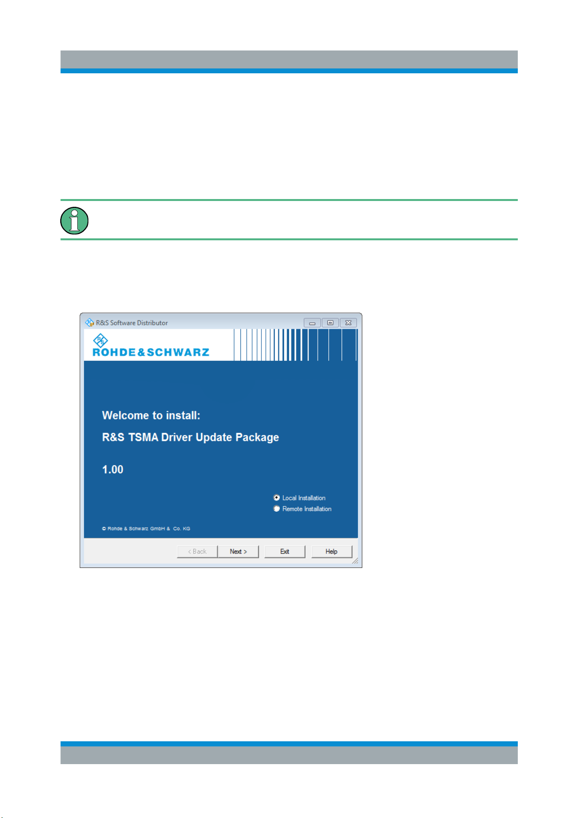
Schwarz web site and run it.
The "R&S Software Distribution" welcome to install page opens.
Figure 4-24: R&S Software Distributor opening page
2. Select "Local Installation" and click "Next".
The opened page shows the contents of the "R&S TSMA Driver Update Package 1.00".
28Getting Started 1177.5604.02 ─ 10
Page 29
R&S®TSMA
Preparing for Use
R&S TSMA Driver Update
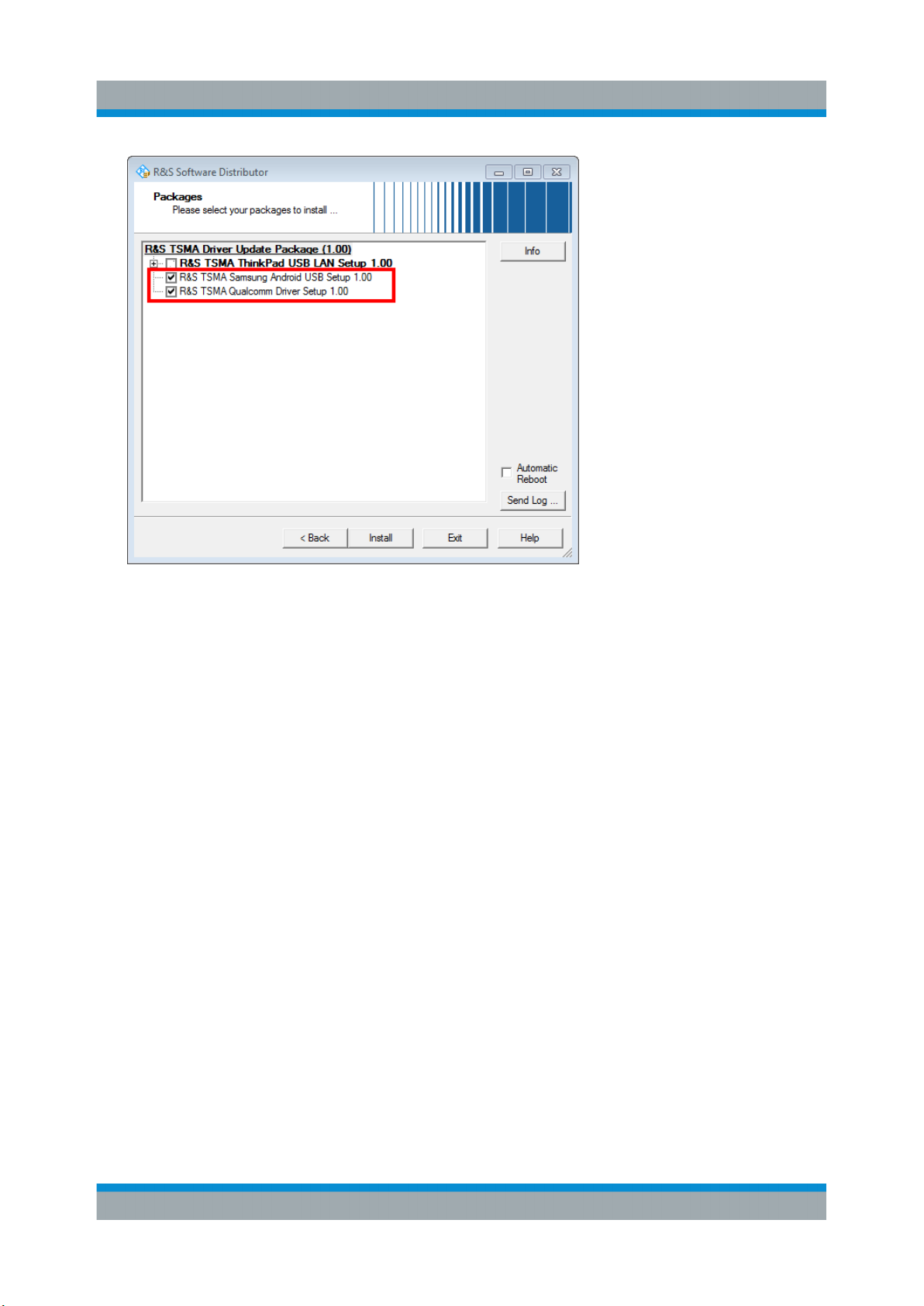
Figure 4-25: Contents of the R&S TSMA Driver Update Package
3. Select "R&S TSMA Samsung Android USB Setup 1.00" and "R&S TSMA
Qualcomm Driver Setup 1.00"and click "Install".
4. Close the installation.
The tool installs the required packages.
For more, see ROMES UE Application.pdf included in the delivered R&S
ROMES DVD.
29Getting Started 1177.5604.02 ─ 10
Page 30
R&S®TSMA
Instrument Tour
Rear Panel
5 Instrument Tour
5.1 Front Panel
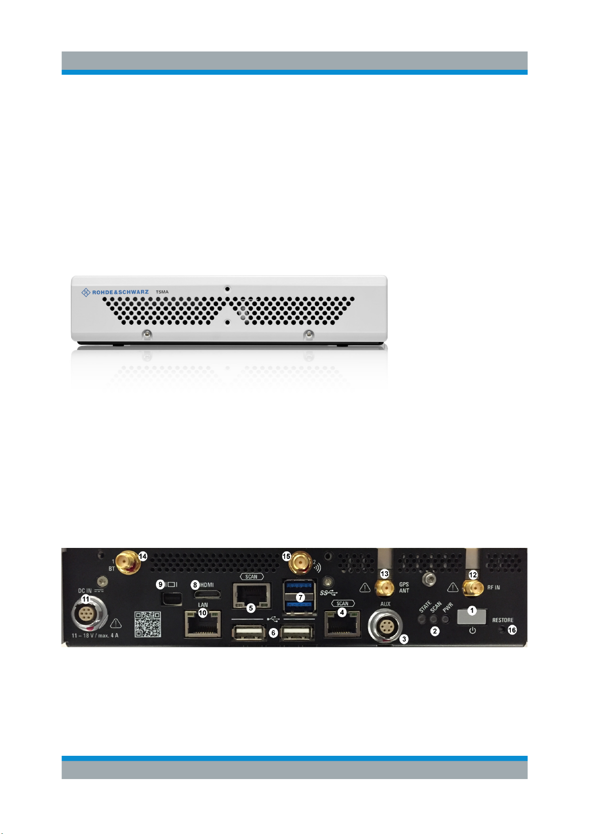
The front panel of the R&S TSMA does not provide any connectors or control elements for operation.
Figure 5-1: R&S TSMA - Front Panel
5.2 Rear Panel
The following figure provides an overview of the control elements and the connectors on the rear panel of the instrument.
Figure 5-2: R&S TSMA - Rear Panel
1 = POWER ON/OFF
2 = STATUS LEDs
3 = AUX Connector
30Getting Started 1177.5604.02 ─ 10
Page 31

R&S®TSMA
Instrument Tour
Rear Panel
4 = SCAN (scanner port from scanner)
5 = SCAN (scanner port to embedded PC)
6 = USB 2.0 (2x)
7 = USB 3.0 (2x)
8 = mini HDMI
9 = MINI Display Port
10 = LAN Connector CPU
11 = DC IN Connector
12 = RF IN Connector
13 = GPS Antenna Connector
14 =
Antenna 1 Connector (Bluetooth® / WLAN MIMO)
15 = Antenna 2 Connector (WLAN)
16 = RESTORE
POWER ON/OFF
The POWER ON/OFF key turns on and off the device if power is supplied via the
DC IN connector.
STATUS LEDs
The three status LEDs, STATE, SCAN, PWR, indicate the operating status of the
R&S TSMA. For a detailed description, see Chapter 5.3, "Status LEDs",
on page 34.
AUX Connector
The AUX connector can be used to synchronize the R&S TSMA with the external
10 MHz reference frequency output of a signal generator or to synchronize multiple R&S TSMA/TSME in a MIMO setup; the Sync cable is necessary.
SCAN (2x)
The two SCAN connectors are used to establish a high-speed data link between
the R&S TSMA scanner unit (SCAN connector on the right side) and the R&S
TSMA internal PC unit (SCAN connector on the left side).
31Getting Started 1177.5604.02 ─ 10
Page 32
R&S®TSMA
Instrument Tour
Rear Panel
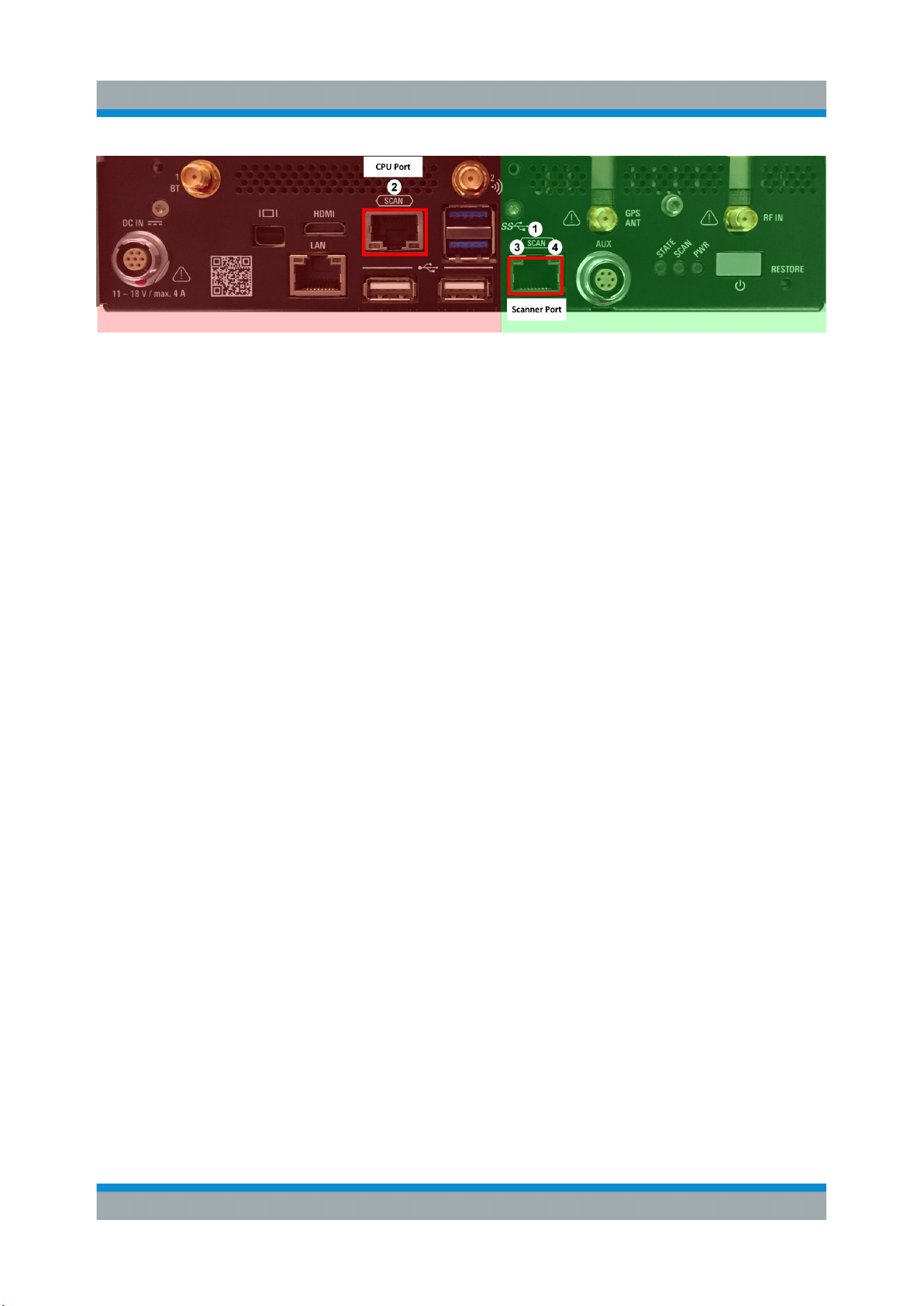
Figure 5-3: Connectors of the R&S TSMA
red side = Internal PC unit of R&S TSMA
green side = Scanner Unit of the R&S TSMA
1 = SCAN Link: Scanner port (used for PC connection in mode "Scanner only")
2 = SCAN Link: CPU port of R&S TSMA
3 = SCAN Link LED1 (link status)
4 = SCAN Link LED2 (activity status)
SCAN Link LEDs
The LEDs on the SCAN connectors display the status of the scan link interconnection. For a detailed description, see Chapter 5.3.2, "SCAN LINK",
on page 36.
USB 2.0 (2x)
The two USB 2.0 ports can be used for connecting external devices as keyboard,
mouse or other devices.
USB 3.0 (2x)
The two USB 3.0 ports can be used for connecting external storage devices, data
sticks and test mobile phones.
Mini-HDMI Port
The MINI-HDMI port can be used for connecting an external monitor. (max. resolution: 2560 x 1600 pixel)
MINI-Display Port
The MINI-Display port can be used for connecting an external monitor. (max. resolution: 5120 x 2880 pixel)
32Getting Started 1177.5604.02 ─ 10
Page 33
R&S®TSMA
LAN
The LAN connector provides a high-speed 100 Mbit Ethernet interface with an RJ
45 connector using IPv4. It is used to connect the R&S TSMA to a host PC in a
local network.
The LAN interface can be used for Remote Control / Remote Desktop Connections. In this case, the device must not be in the "Scanner Only" mode.
Alternatively, it can also be used for distributed versions of R&S ROMES
and R&S NESTOR.
The LEDs on the LAN connector indicate the status of the connection to the host
PC. LED 1 (yellow, link status) is on the left side of the connector, LED 2 (green,
activity status) is on the right.
Instrument Tour
Rear Panel
DC IN Connector
The DC IN connector is used to supply the R&S TSMA with DC power. A wide DC
input range 10 to 18 V / max. 4 A is supported.
Use only cable type with R&S No. 1523.7948.00 (included in delivery package).
RF IN Connector
The RF IN connector is the RF input of the R&S TSMA. The multi-band RF paddle antenna (700 MHz to 2.6 GHz), which is included in the shipment of R&S
TSMA or any customer side RF source is connected to this SMA connector. The
maximum input power is +20 dBm/10 V DC.
For the multi-band RF paddle antenna (700 MHz to 2.6 GHz), no adapter is
required.
Risk of instrument damage
Do not overload the maximum allowed input of 20 dBm.
Non-compliance destroys the input mixer.
33Getting Started 1177.5604.02 ─ 10
Page 34
R&S®TSMA
GPS ANT
This SMA port is used for the GPS antenna input. It is an active antenna port with
output voltage 3 V / max. 35 mA.
The accessory GPS antenna is connected to this input.
Antenna Connector 1 BT
The port with the label "1 BT" is a combined Bluetooth / WLAN antenna port.
Connect the accessory WLAN / Bluetooth stub antenna to this SMA connector.
Antenna Connector 2 WLAN
Instrument Tour
Status LEDs
The port with the label "2
accessory WLAN / Bluetooth antennas to this SMA connector.
RESTORE
With the RESTORE button, it is possible to bring the R&S TSMA back to factory
default.
Loss of user data after RESTORE
Executing restore brings the R&S TSMA irreversible back to the condition of
delivery or any other later stored backup version.
All user data since last restore is lost.
" is the WLAN antenna port. Connect one of the
5.3 Status LEDs
5.3.1 PWR, SCAN, STATE
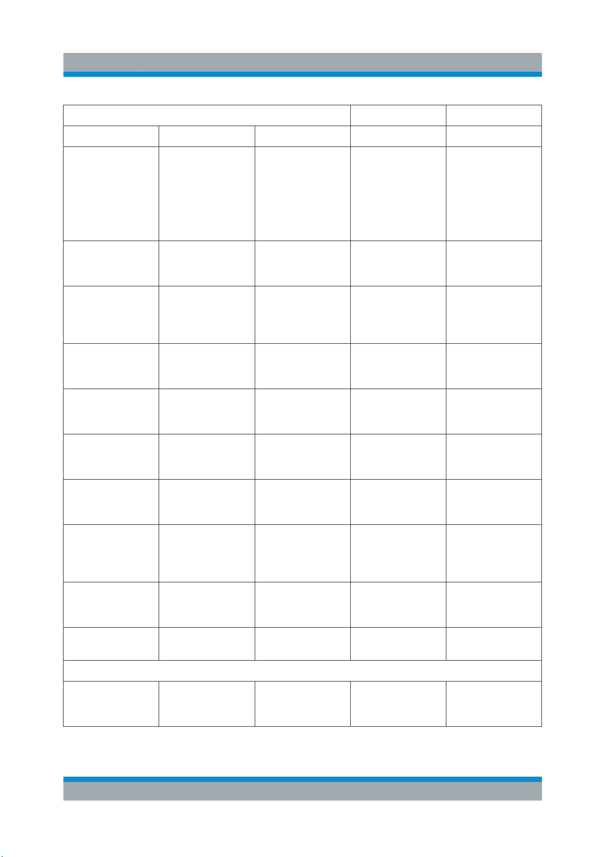
The three status LEDs on the rear panel indicate the following states.
34Getting Started 1177.5604.02 ─ 10
Page 35
R&S®TSMA
Instrument Tour
Status LEDs
LEDs Mode Comment
PWR SCAN STATE x x
green (blinking
slowly)
off - amber (cont.) "Scanner Only"
blue (10 sec) ->
green (10 sec) ->
off
blue off amber (cont.) Idle / WLAN On Device powered /
blue off green (cont.) Idle / WLAN Off Device powered /
blue green LED controlled
off off Delayed start
enabled
Mode
- green (blinking
1Hz)
by software application
Power up / selftest
Ready Scanner module
R&S TSMA will
auto power on
after a delay
which was configured in the webGUI during previous session.
Only the scanner
module is powered.
Power up cycle in
progress after
switching on via
power button.
idle state / WLAN
AP is on
idle state / WLAN
AP is off
connected / no
measurement
blue green (flashing
rapidly)
blue amber (2 sec.) ->
red (2 sec.) ->
off
blue - white Firmware update
blue / green
(alternating)
Error States
blue red (blinking 2
- - CPU in sleep
Hz)
LED controlled
by software application
green (blinking
1Hz)
- Temperature
Busy Active scanner
Power down in
progress
– microcontroller
flash in progress
mode
warning scanner
module
measurement
running
Power down in
progress when
switched off via
power button.
-
-
-
35Getting Started 1177.5604.02 ─ 10
Page 36
R&S®TSMA
Instrument Tour
Status LEDs
LEDs Mode Comment
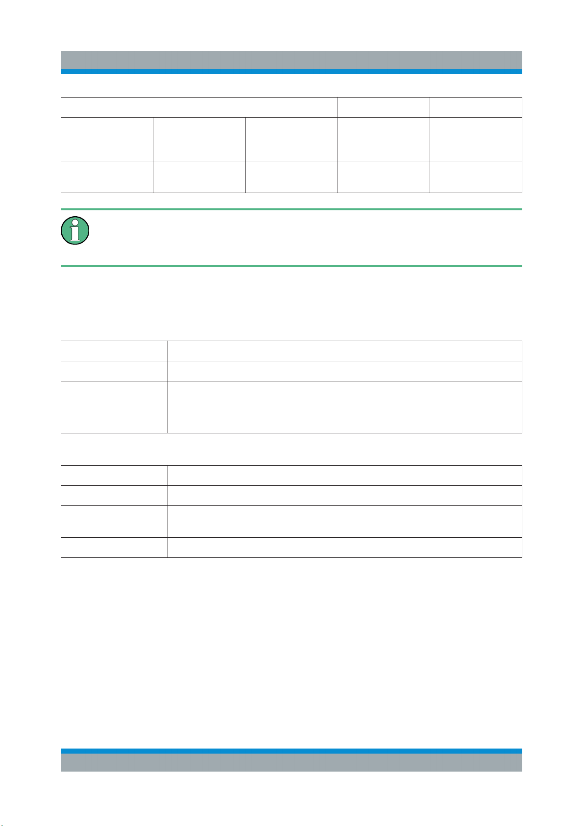
blue red (cont.) - Temperature
error scanner
module
blue - red Scanner link
failed
-
This description of the STATE LED is based on the initial firmware. If the
R&S TSMA is working in a specific mode, e.g. ROMES, NESTOR, ViCom
or QualiPoc, the STATE LED may be used for these applications.
5.3.2 SCAN LINK
Table 5-1: SCAN Link LED1 (link) states and their meaning
LED state Description
off No link
yellow, blinking Identify scanner module (TSME Device Manager test), (synchronous
with SCAN LED and SCAN Link LED2)
yellow Link established
Table 5-2: SCAN Link LED2 (activity) states and their meaning
LED state Description
off No data
green, blinking Identify scanner module (TSME Device Manager test), (synchronous
with SCAN LED and SCAN Link LED1)
green, flashing Data transfer on scan link
36Getting Started 1177.5604.02 ─ 10
Page 37

R&S®TSMA
Configuring the R&S TSMA
Accessing the R&S TSMA
6 Configuring the R&S TSMA
6.1 Accessing the R&S TSMA
There are different ways to access the R&S TSMA.
●
Local operation
To use the R&S TSMA as an ordinary PC, an external monitor, mouse and
keyboard have to be connected to the R&S TSMA.
●
Remote access
The remote access to the R&S TSMA can be realized via the following
options.
– Using the Web-GUI of the R&S TSMA (see Chapter 6.1.1, "Start the R&S
TSMA Web-GUI", on page 37 ).
– Establish a remote desktop connection (via LAN/WLAN) (see Chap-
ter 6.1.2, "Establish a Remote Desktop Connection", on page 38).
6.1.1 Start the R&S TSMA Web-GUI
To start the R&S TSMA Web-GUI via a remote PC, three possible ways are available.
WLAN
1. Via a tablet or smartphone, you have to establish a WLAN connection to R&S
TSMA WLAN access point.
a) Search for a TSMA WLAN network. The WLAN access point on the R&S
TSMA is started automatically by default during the boot process of the
device.
NOTE: This behavior can be switched off.
b) Connect your tablet or smartphone with the TSMA WLAN network. The
required login information can be found on a label on the bottom side of
the R&S TSMA base unit.
WLAN-Access Point SSID: TSMA-xxxxxx (xxxxxx is the serial number of
this specific R&S TSMA)
Key: instrument
37Getting Started 1177.5604.02 ─ 10
Page 38

R&S®TSMA
The WLAN connection between the tablet or smartphone and the R&S TSMA
device is established.
2. On the tablet or smartphone start a web browser and enter the following URL:
http://192.168.1.10/
The configuration Web-GUI of the R&S TSMA is started.
LAN
1. Connect the R&S TSMA LAN port with the host PC port.
2. Use the R&S TSMA default IP settings, that is, the DHCP Client. The R&S
TSMA and the remote host PC automatically negotiate the IP address.
3. Alternatively, use the fixed address. Start a web browser via the R&S TSMA
Web-GUI and enter the following URL:
http://TSMA-<xxxxxx>.local (xxxxxx is the serial number of this specific R&S
TSMA)
Configuring the R&S TSMA
Accessing the R&S TSMA
Local access from the R&S TSMA and Windows Explorer
► Open Internet Explorer using mouse, keyboard and monitor. The R&S TSMA
Web-GUI opens automatically. If not, type the following:
http://localhost
6.1.2 Establish a Remote Desktop Connection
To establish a remote desktop connection, the following steps must be performed:
1. A WLAN/LAN connection between the R&S TSMA and the remote PC has to
be established, see Chapter 6.1.1, "Start the R&S TSMA Web-GUI",
on page 37.
2. On the external PC, navigate to "Programs" > "Accessories" > "Remote Desktop Connection".
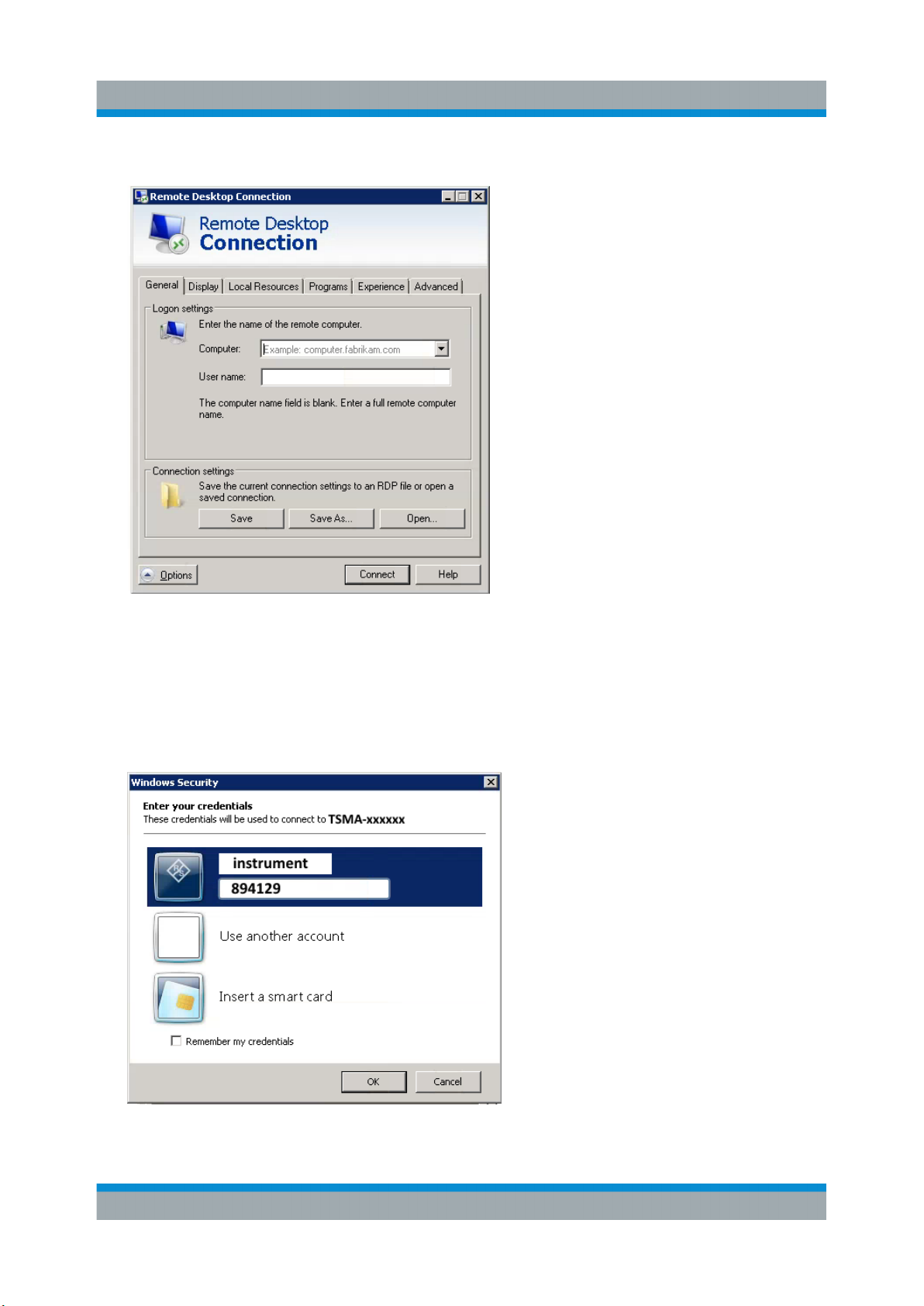
3. In the "Remote Desktop Connection" window, click "Options".
4. In the "General" tab, enter following parameters:
● Computer: The input depends on selected connection type, see the Chap-
ter 6.1.1, "Start the R&S TSMA Web-GUI", on page 37 and is .
– WLAN: 192.168.1.10
– LAN: IP address of the R&S TSMA
38Getting Started 1177.5604.02 ─ 10
Page 39
R&S®TSMA
● User name: instrument
Configuring the R&S TSMA
Accessing the R&S TSMA
Note: For access via IP address, use the following IP addresses:
● WLAN: 192.168.1.10
● LAN: IP address is assigned by the host PC
5. Click "Connect".
6. Enter the password 894129 and click "OK".
39Getting Started 1177.5604.02 ─ 10
Page 40
R&S®TSMA
Changing Password of R&S TSMA
7. The remote desktop connection is established.
The R&S TSMA can be controller as a standard PC.
Configuring the R&S TSMA
6.2 Changing Password of R&S TSMA
To change the default password (default PW: 894129) of R&S TSMA, proceed as
follows. After changing the password, additional steps has to be performed for
"Autologin".
Change Password
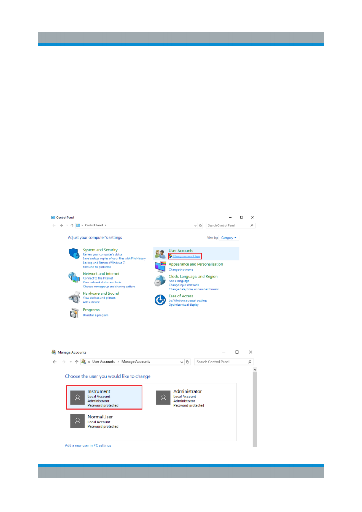
1. On R&S TSMA, open the "Control Panel".
2. Navigate to "User Accounts" > "Change account type".
3. In the following window, double-click the account "instrument" to edit the settings.
40Getting Started 1177.5604.02 ─ 10
Page 41
R&S®TSMA
Changing Password of R&S TSMA
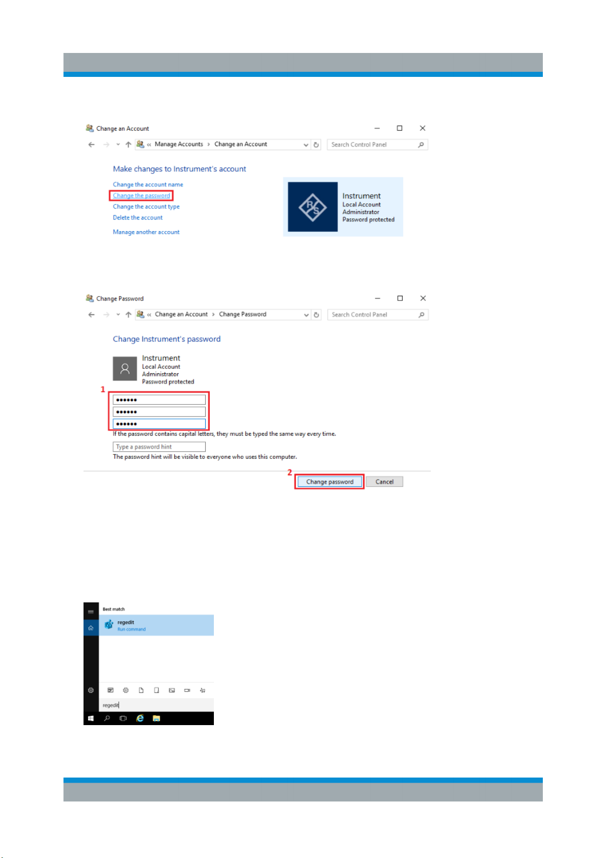
4. Click "Change the password".
5. Fill in the fields (1) and click "Change password" (2).
Configuring the R&S TSMA
Enable Autologin
After changing the password, change the password also in "Autologin" settings.
To change the "Autologin" settings, proceed as follows.
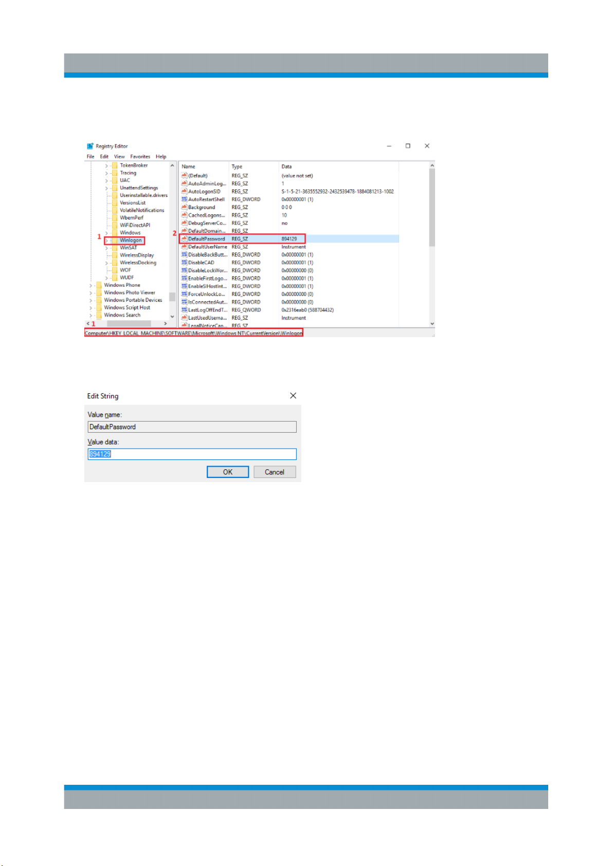
1. Open the "Registry Editor".
2. In the "Registry Editor", navigate to
HKEY_LOCAL_MACHINE\SOFTWARE\Microsoft\Windows NT\
41Getting Started 1177.5604.02 ─ 10
Page 42
R&S®TSMA
CurrentVersion\Winlogon (1) and double-click the parameter "Default
Password" (2).
3. The "Edit the default password" window is opening.
Under "Value data", type in the new password.
Configuring the R&S TSMA
Measurement Setup
4. Click "OK". The changes are accepted. After powering, the R&S TSMA automatically login.
6.3 Measurement Setup
The measurement setup procedure is performed in the following steps.
1. Start the R&S TSMA Web-GUI (see Chapter 6.1.1, "Start the R&S TSMA
Web-GUI", on page 37).
2. Check the prerequisites of the desired measurement mode (see Chapter 6.4,
"Measurement Modes", on page 43) and adjust your device according these
requirements.
42Getting Started 1177.5604.02 ─ 10
Page 43
R&S®TSMA
3. If the required application is not yet installed, install the required application
(Details can be found in the R&S TSMA User Manual).
4. Select the measurement mode in the R&S TSMA Web-GUI; the modes are
described in Chapter 6.4, "Measurement Modes", on page 43.
The R&S Remote ViCom Server is installed on all the R&S TSMAs.
The other software applications, that is, the R&S NESTOR, R&S ROMES
and QualiPoc are installed only if ordered.
Configuring the R&S TSMA
Measurement Modes
6.4 Measurement Modes
To setup a measurement, see Chapter 6.3, "Measurement Setup", on page 42.
The R&S Remote ViCom Server is installed on all the R&S TSMAs.
The other software applications, that is, the R&S NESTOR, R&S ROMES
and QualiPoc are installed only if ordered.
6.4.1 Remote ViCom Server Mode
The connection between the Remote Vicom server on the R&S TSMA and the client application (Remote ViCom client) on the handheld device can be realized via
Bluetooth® or WLAN.
Based on the connection type, different steps are necessary.
The selection of the connection type depends on the measurement task.
The WLAN connection allows a throughput, which is about 10 times higher
compared to Bluetooth.
On the other hand, the Bluetooth connection is less influenced by interference.
43Getting Started 1177.5604.02 ─ 10
Page 44
R&S®TSMA
Requirements for using the Bluetooth® interface
The device must be in the PC Mode. Check it via the Web-GUI ("Overview"
> "Mode of Operation").
1.
Switch on Bluetooth® on R&S TSMA.
2. The tablet/smartphone must be paired with the R&S TSMA.
Requirements for using the WLAN interface
1. Switch on the WLAN AP on the R&S TSMA.
2. Switch on WLAN on the tablet/smartphone.
3. Connect the tablet/smartphone with the R&S TSMA WLAN AP.
Configuring the R&S TSMA
Measurement Modes
Measurement
To run measurements, the requirements for operating the rViCom Sample App
have to be fulfilled, see R&S TSMA User Manual.
1. Activate the rViCom Server mode (see Chapter 6.3, "Measurement Setup",
on page 42).
2. Start one of the following applications
a) Start the OEM rViCom client application on the mobile device.
b) Start the rViCom Sample App on the mobile device.
For more details, refer to R&S TSMA User Manual.
6.4.2 QualiPoc Mode
To use the R&S TSMA with QualiPoc®, the following steps must be performed.
Prerequisites
●
A scanner license must be installed on the QualiPoc® handheld device.
●
On the R&S TSMA, Bluetooth® must be activated and visible.
●
The "Mode of Operation" must be set to "QualiPoc".
1. After selecting mode of operation, the R&S TSMA reboots.
44Getting Started 1177.5604.02 ─ 10
Page 45
R&S®TSMA
Configuring the R&S TSMA
Measurement Modes
2. The complete startup of the "QualiPoc" mode takes about 3 minutes.
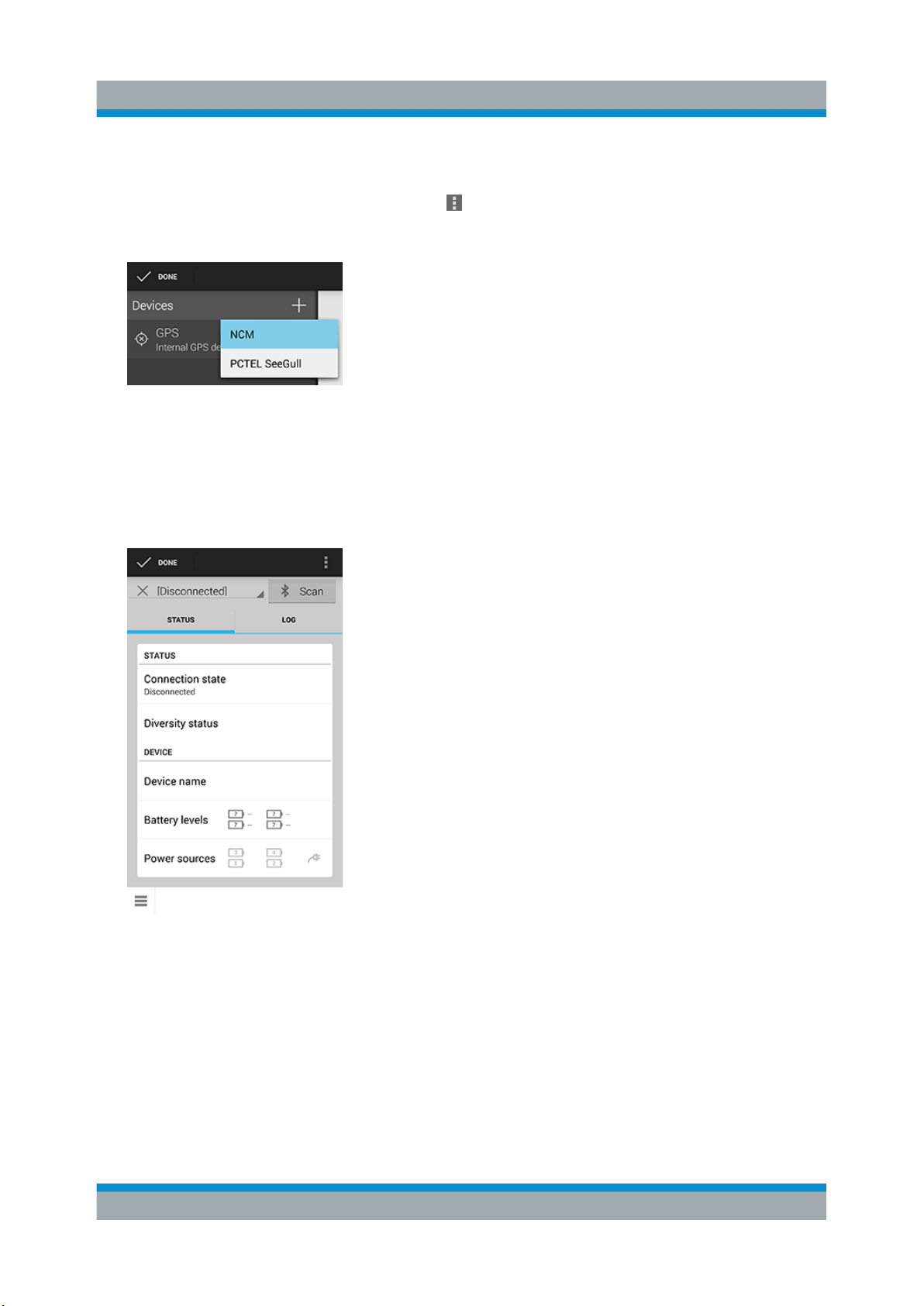
3.
In QualiPoc®, touch the main menu , and then touch "Device manager".
4. Touch the plus sign (+) at the top of the screen and touch "NCM".
Figure 6-1: Add NCM
Note: The NCM provides the Bluetooth® connection to the scanner.
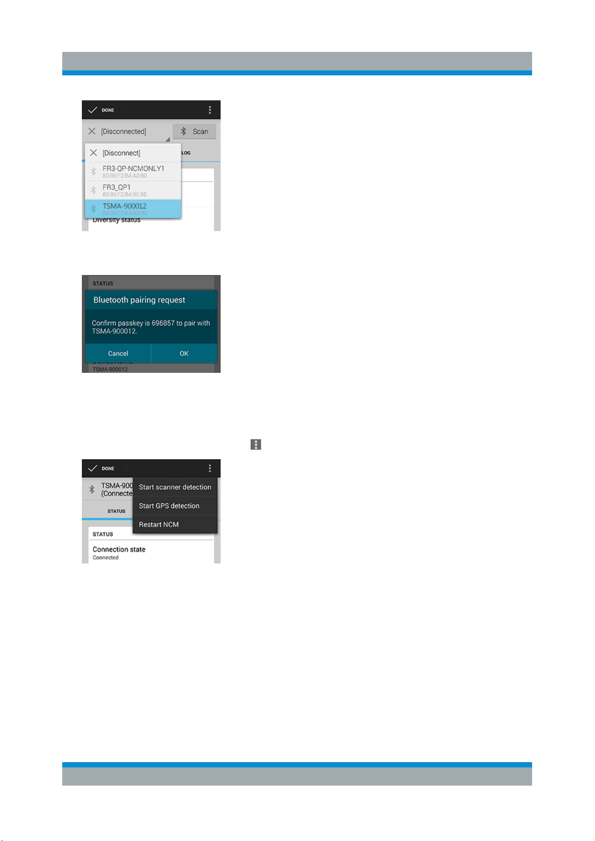
5. Touch "Scan" at the top of the screen and wait until the scanning process
stops.
Figure 6-2: Scan for NCM
6. Touch "[Disconnected]", touch the TSMA scanner in the list, for example,
"TSMA-900012", and then touch to accept the pairing request.
45Getting Started 1177.5604.02 ─ 10
Page 46
R&S®TSMA
Figure 6-3: Pair NCM
Configuring the R&S TSMA
Measurement Modes
Figure 6-4: Bluetooth pairing request
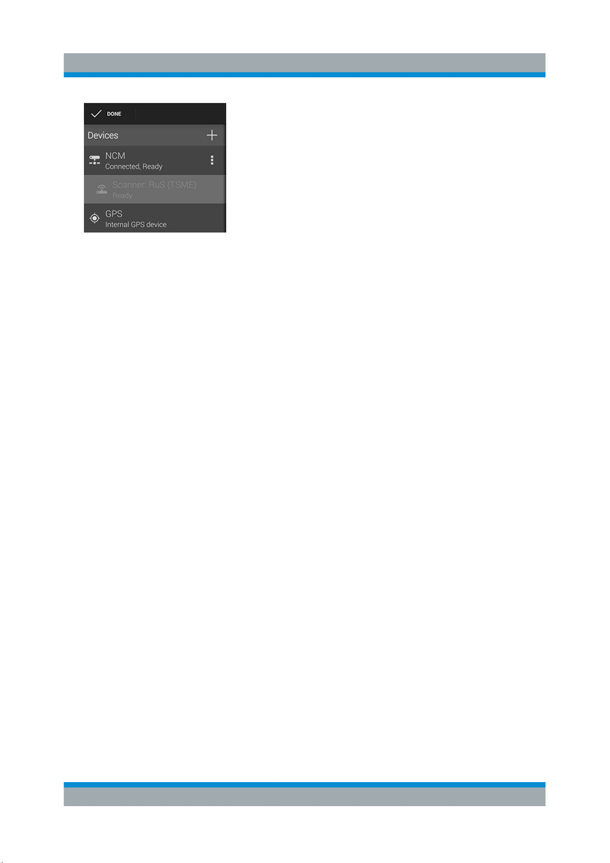
7. Touch the scanner again in the list to connect to the scanner.
8. Touch the context menu icon and touch "Start scanner detection".
Figure 6-5: Start scanner detection
The scanner appears in the "Devices" list upon successful detection.
46Getting Started 1177.5604.02 ─ 10
Page 47
R&S®TSMA
Figure 6-6: Scanner ready
For more details about the QualiPoc configuration and usage, refer to the user
documentation for QualiPoc®.
Configuring the R&S TSMA
Measurement Modes
6.4.3 NESTOR and NESTOR Probe Mode
In the "NESTOR" mode, which can be started only if the R&S NESTOR is installed, otherwise is dimmed, the R&S NESTOR software is hosted on the R&S
TSMA. The selection of a valid workspace file is required.
In the "NESTOR Probe" mode, the NESTOR application operates in a distributed
mode and only the NESTOR measurement engine is hosted on the R&S TSMA.
Configuration and control of the measurement is done on a remote PC.
To use the R&S TSMA in "NESTOR" mode, the following steps must be performed.
Prerequisites:
●
R&S TSMA-NESTOR software package must be installed on the R&S TSMA.
The software package is pre-installed at delivery when the R&S TSMA is
ordered with NESTOR TSMA Option. (R&S No. 1522.8870.03).
Note: The R&S®NESTOR software installation can be executed as a post
process to shipment.
●
Only for "NESTOR" mode
A dongle containing a smart card with R&S NESTOR option licenses must be
available.
Note: If the R&S TSMA is delivered with a pre-installed R&S NESTOR software, the NESTOR smart card is integrated inside the TSMA instrument and
no license dongle is necessary.
●
Only for "NESTOR Probe" mode
47Getting Started 1177.5604.02 ─ 10
Page 48

R&S®TSMA
The R&S TSMA and the external PC must be connected via WLAN or the
LAN port of the R&S TSMA.
Import of NESTOR Workspace File
Importing of the R&S NESTOR workspace file is an additional requirement for
operating in the "NESTOR" mode.
1. Start the R&S TSMA Web-GUI.
2. Navigate to "File Transfer/Update" menu and go to section "Upload File to
TSMA".
3. Press the "Browse" button, select the desired workspace file on the remote
PC and click "Upload File".
The file will be copied in the directory
D:\Users\Instrument\Documents\NESTOR\FavoriteWorkspace.
The file is available from the "System" > "Operation Mode" > "NESTOR" workspace select-box.
Configuring the R&S TSMA
Measurement Modes
Measurement
To use the "NESTOR" or "NESTOR Probe" mode, the following steps must be
performed.
1. In the Web-GUI, change the "Mode of Operation" to "NESTOR" or "NESTOR
Probe" (see Chapter 6.3, "Measurement Setup", on page 42).
2. According to the selected mode, following additional settings are required.
a) "NESTOR" mode
Select a workspace.
b) "NESTOR Probe" mode
Client and server detect each other automatically when connected via LAN
resp. WLAN.
The NESTOR application must be started on the host PC/tablet. The NESTOR software installed on the host PC controls the measurement.
3. Click "Submit" to save your selection.
In the case, the TSMA is rebooted and starts a NESTOR measurement with
the selected workspace file.
In the case, Client and Server detect each other automatically if connected via
LAN resp. WLAN.
48Getting Started 1177.5604.02 ─ 10
Page 49
R&S®TSMA
For more details about the R&S NESTOR configuration and usage, refer to the
user documentation for R&S NESTOR.
Configuring the R&S TSMA
Measurement Modes
6.4.4 ROMES Mode
In the "ROMES" mode, the ROMES software is hosted on the R&S TSMA and
the selection of a valid workspace file is required.
The ROMES mode is only displayed if the ROMES setup has been executed (see R&S TSMA User Manual).
For the first time after installation, R&S ROMES has to be started from the
Windows desktop icon. After closing R&S ROMES, now it is possible to
start R&S ROMES via the R&S TSMA Web-GUI.
To use the R&S TSMA with R&S ROMES, the following steps must be performed.
Prerequisites:
●
R&S TSMA-ROMES software package
(TSMA-ROMES-setup-<version>.exe) has to be installed on the R&S
TSMA (see R&S TSMA User Manual)
●
A ROMES license dongle must be connected to a USB port of the R&S
TSMA.
Import of ROMES Workspace File
Importing of the R&S ROMES workspace file is an additional requirement for
operating in the "ROMES" mode.
1. Start the R&S TSMA Web-GUI.
2. Navigate to "File Transfer/Update" menu and go to section "Upload File to
TSMA".
3. Press the "Browse" button, select the desired ROMES workspace file on the
remote PC and click "Upload File".
4. The file will be copied by default in the directory
C:\ProgramData\Rohde&Schwarz\My ROMES\Workspace.
49Getting Started 1177.5604.02 ─ 10
Page 50

R&S®TSMA
Measurement
To use the "ROMES" mode, the following steps must be performed.
1. In the Web-GUI, change the "Mode of Operation" to "ROMES" or "ROMES
Probe" (see Chapter 6.3, "Measurement Setup", on page 42).
2. Configure the following settings:
● Workspace File
In the drop-down menu, select a ROMES workspace file.
● Recording
Activating this checkbox, the ROMES measurement data are written to the
TSMA hard disk.
● IP Controlled
Activating this checkbox, the ROMES measurement can be controlled via
IP from an external host PC. To use this feature, the ROMES option
ROMES4RCO is required.
Configuring the R&S TSMA
Measurement Modes
3. Click "Submit" to save your selection.
For more details about the R&S®ROMES configuration and usage, refer to the
user documentation for R&S®ROMES.
6.4.5 PC Mode
The "PC Mode" is used for software update of the R&S TSMA.
6.4.6 Scanner Only Mode
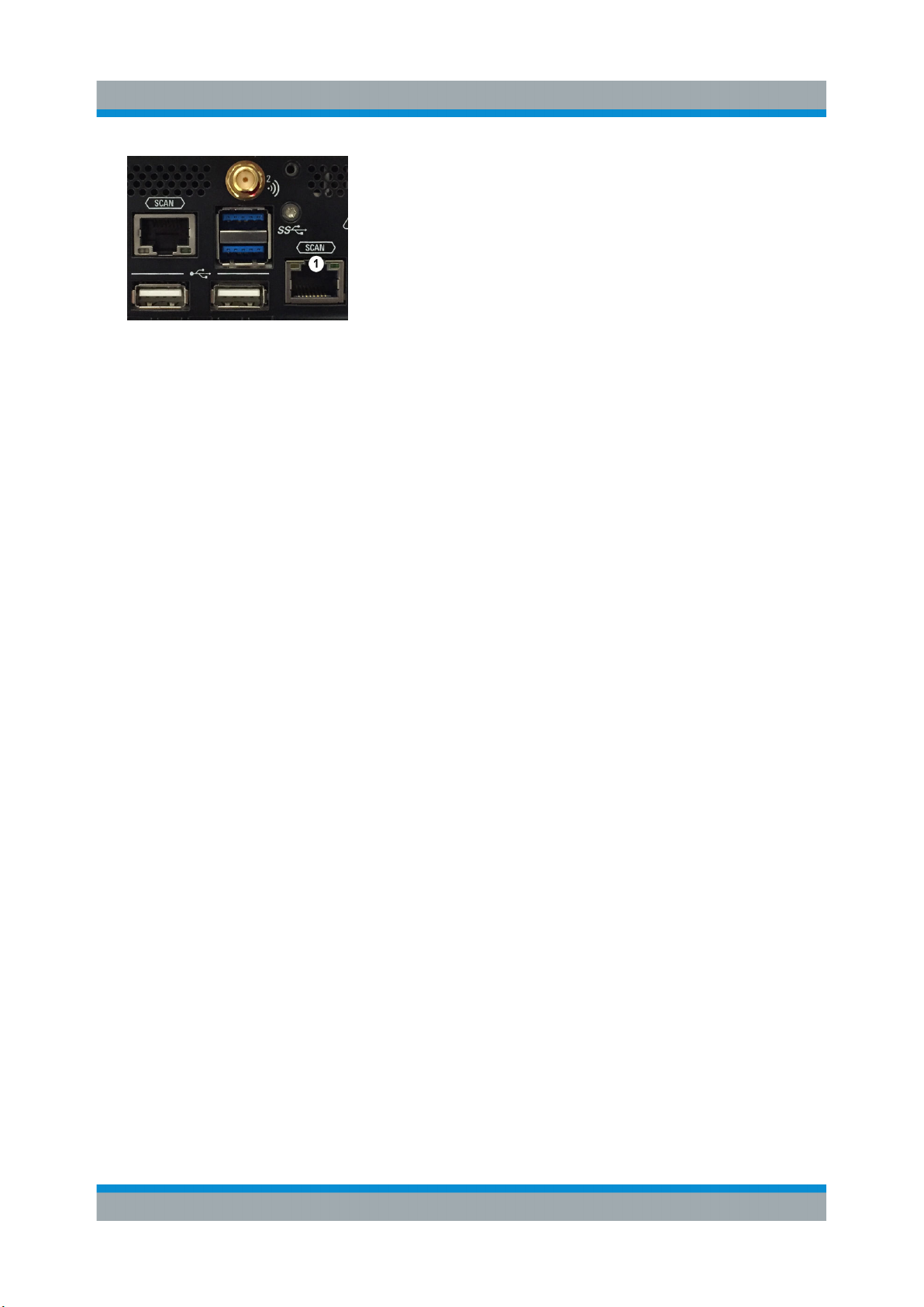
In the scanner only mode, only the scanner unit of the R&S TSMA is active, the
PC unit is in stand-by mode. In this case, the scanner unit (R&S TSME) can be
connected via the SCAN port 1 with a host PC.
To use the R&S TSMA in scanner only mode, the following steps must be performed.
1. Switch off the R&S TSMA and activate the scanner only mode by pressing the
POWER ON/OFF button more than 2 s and less than 5 s.
The STATE LED lights yellow.
2. Connect the scan port (1) with your PC.
50Getting Started 1177.5604.02 ─ 10
Page 51
R&S®TSMA
Figure 6-7: Scan ports of R&S TSMA
1 = Scan port to be connected with PC in scanner only mode
The default IP address of the R&S TSMA scanner component is 192.168.0.2.
Configuring the R&S TSMA
Power Settings
6.5 Power Settings
The power settings for an R&S TSMA can be modified according to following
rules.
With the setting "Auto Power On", the R&S TSMA starts automatically, when a
DC power supply is connected.
With the setting "Remember Last State", the R&S TSMA uses the last state
before the R&S TSMA was powered off.
Additionally. the setting "Auto Power Off" can be activated. In this case, the R&S
TSMA is powered off, if a DC power supply is no longer available.
51Getting Started 1177.5604.02 ─ 10
Page 52

R&S®TSMA
Index
B
Brochures .................................................. 6
D
Data sheets ............................................... 6
G
Getting started ...........................................6
H
HDMI Port ................................................32
Help ........................................................... 6
L
LED
LAN Connector ................................... 33
Status ..................................................31
Index
M
MINI-Display Port .................................... 32
O
Open source acknowledgment (OSA) .......7
R
Release notes ........................................... 7
S
Safety instructions ..................................... 6
U
User manual .............................................. 6
52Getting Started 1177.5604.02 ─ 10
 Loading...