


 Loading...
R&S®TSME6
Ultracompact Drive Test Scanner
User Manual
(a00Q2)
4900003302
User Manual |
Version 04 |
This manual applies to the following R&S®TSME6 models and options:
●R&S®TSME6 (4900.0004.02)
●Block IQ Option R&S®TSME6-K10 (4900.2459.02)
●TD-SCDMA Option R&S®TSME6-K20 (4900.2220.02)
●WCDMA Scanner Option R&S®TSME6-K21 (4900.2188.02)
●CDMA2000® Option R&S®TSME6-K22 (4900.2165.02)
●GSM Scanner Option R&S®TSME6-K23 (4900.2194.02)
●1xEVDO Rev. A Scanner Option R&S®TSME6-K24 (4900.2142.02)
●CW Scanner Option R&S®TSME6-K25 (4900.2242.02)
●TETRA Scanner Option R&S®TSME6-K26 (4900.2142.02)
●RF Power Scan Option R&S®TSME6-K27 (4900.2120.02)
●WiMAX™ Scanner Option R&S®TSME6-K28 (4900.2136.02)
●LTE Scanner Option R&S®TSME6-K29 (4900.2171.02)
●LTE MIMO 2x2, 4x2, 4x4 R&S®TSME6-K30 (4900.2113.02)
●LTE eMBMS Option R&S®TSME6-K32 (4900.2288.02)
●NB-IoT/Cat NB1 Scanning R&S®TSME6-K34 (4900.2207.02)
●LTE M Option R&S®TSME6-K35 (4900.2465.02)
●Automatic Channel Detection R&S®TSME6-K40 (4900.2259.02)
●5G NR Scanning Option R&S®TSME6-K50 (4900.2436.02)
●BTS PE Enabler R&S®TSME6-K80 (4900.2442.02)
© 2020 Rohde & Schwarz GmbH & Co. KG
Mühldorfstr. 15, 81671 München, Germany Phone: +49 89 41 29 - 0
Fax: +49 89 41 29 12 164 Email: info@rohde-schwarz.com
Internet: www.rohde-schwarz.com
Subject to change – Data without tolerance limits is not binding.
R&S® is a registered trademark of Rohde & Schwarz GmbH & Co. KG.
Trade names are trademarks of the owners.
4900.0033.02 | Version 04 | R&S®TSME6
Throughout this manual, products from Rohde & Schwarz are indicated without the ® symbol , e.g. R&S®TSME6 is indicated as R&S TSME6.

R&S®TSME6 |
Contents |
|
Contents |
|
1 |
Preface.................................................................................................... |
5 |
1.1 |
Documentation Overview............................................................................................. |
5 |
1.1.1 |
Getting Started Manual................................................................................................... |
5 |
1.1.2 |
User Manuals and Help................................................................................................... |
5 |
1.1.3 |
Tutorials........................................................................................................................... |
5 |
1.1.4 |
Basic Safety Instructions................................................................................................. |
5 |
1.1.5 |
Brochures........................................................................................................................ |
5 |
1.1.6 |
Application Notes, Application Cards, White Papers, etc................................................ |
6 |
1.2 |
Safety and Regulatory Information............................................................................. |
6 |
1.2.1 |
Korea Certification Class B............................................................................................. |
6 |
2 |
Key Features........................................................................................... |
7 |
3 |
Instrument Tour...................................................................................... |
8 |
3.1 |
Front Panel View........................................................................................................... |
8 |
3.2 |
Rear Panel View............................................................................................................. |
9 |
4 |
Option Concept.................................................................................... |
12 |
4.1 |
Technology Options.................................................................................................... |
12 |
4.2 |
Band Options............................................................................................................... |
13 |
4.3 |
Option Sharing Concept............................................................................................. |
13 |
5 |
Preparing for Use................................................................................. |
15 |
5.1 |
Putting into Operation................................................................................................ |
15 |
5.1.1 |
Unpacking and Checking the Instrument...................................................................... |
16 |
5.1.2 |
Accessory List............................................................................................................... |
17 |
5.1.3 |
Cascading R&S TSME6s.............................................................................................. |
17 |
5.1.4 |
Connecting the DC Power Supply................................................................................. |
20 |
5.1.5 |
Setting Up the LAN Connection to the Host PC............................................................ |
22 |
5.1.5.1 |
Configuring the LAN Interface on the Host PC............................................................. |
23 |
5.1.5.2 |
Firewall Configuration................................................................................................... |
26 |
5.1.5.3 |
Connecting the R&S TSME6 to the Host PC................................................................ |
27 |
5.1.6 |
Connecting External Devices........................................................................................ |
27 |
5.1.7 |
Connecting a Kensington Lock..................................................................................... |
28 |
User Manual 4900.0033.02 ─ 04 |
3 |

R&S®TSME6 |
Contents |
5.1.8 |
Enabling Untethered Dead Reckoning ......................................................................... |
28 |
5.2 |
Connecting Multiple R&S TSME6s to One Host PC................................................. |
29 |
5.2.1 |
Using Two R&S TSME6s in Parallel............................................................................. |
29 |
5.2.2 |
LTE MIMO Setups with Two R&S TSME6s................................................................... |
30 |
5.2.3 |
LTE MIMO Setups with Four R&S TSME6s.................................................................. |
32 |
5.3 |
Switching the Instrument On and Off........................................................................ |
35 |
5.4 |
Connecting the R&S TSME6 to a Software Application for the First Time............ |
35 |
6 Configuring the R&S TSME6............................................................... |
39 |
|
6.1 |
Using the R&S TSME Device Manager...................................................................... |
39 |
6.1.1 |
Obtaining Device Information - "Device Info"................................................................ |
40 |
6.1.2 |
Changing IP Addresses - "Network Configuration"....................................................... |
43 |
6.1.3 |
Installing and Managing Software License Keys - "Options"........................................ |
44 |
6.1.4 |
Configuring Measurement Bands - "Band Configuration"............................................. |
46 |
6.1.5 |
Obtaining Firmware and Correction Data Updates - "Updates".................................... |
48 |
6.1.6 |
Aligning R&S TSME6 Manually - "Self Alignment"........................................................ |
49 |
6.1.7Configuring Downconverter R&S TSME30DC/TSME44DC - "Downconverter Configu-
|
ration"............................................................................................................................ |
50 |
6.2 |
Interacting with R&S ROMES, R&S NESTOR, and R&S ViCom.............................. |
52 |
6.2.1 |
Interacting with R&S ROMES....................................................................................... |
52 |
6.2.2 |
Interacting with R&S NESTOR...................................................................................... |
53 |
6.2.3 |
Interacting with R&S ViCom.......................................................................................... |
53 |
7 |
Troubleshooting................................................................................... |
55 |
7.1 |
Guide to Solve Instrument Connection Problems................................................... |
55 |
7.2 |
Solving Other Miscellaneous Problems.................................................................... |
58 |
7.3 |
Contacting Customer Support................................................................................... |
60 |
|
Annex.................................................................................................... |
62 |
A |
Available Cellular Bands..................................................................... |
62 |
|
Index...................................................................................................... |
69 |
User Manual 4900.0033.02 ─ 04 |
4 |

R&S®TSME6 |
Preface |
|
Documentation Overview |
1 |
Preface |
1.1 |
Documentation Overview |
|
This section provides an overview of the R&S TSME6 user documentation. Unless |
|
specified otherwise, you find the documents on the R&S TSME6 product page at: |
|
www.rohde-schwarz.com/manual/tsme6 |
1.1.1 |
Getting Started Manual |
|
Introduces the R&S TSME6 and describes how to set up and start working with the |
|
product. Includes basic operations, typical measurement examples, and general infor- |
|
mation, e.g. safety instructions, etc. A printed version is delivered with the instrument. |
1.1.2 User Manuals and Help |
|
|
Contains the description of all instrument modes and functions. It also provides infor- |
|
mation on maintenance, instrument interfaces and error messages. Includes the con- |
|
tents of the getting started manual . |
1.1.3 |
Tutorials |
|
Tutorials offer guided examples and demonstrations on operating the R&S TSME6. |
|
They are provided on the internet page of the product. |
1.1.4 |
Basic Safety Instructions |
|
Contains safety instructions, operating conditions and further important information. |
|
The printed document is delivered with the instrument. |
1.1.5 |
Brochures |
|
The brochure provides an overview of the instrument and deals with the specific char- |
|
acteristics and contains the technical specifications of the R&S TSME6. It also lists the |
|
firmware applications and their order numbers, and optional accessories. |
See www.rohde-schwarz.com/brochure-datasheet/tsmx
User Manual 4900.0033.02 ─ 04 |
5 |

R&S®TSME6 |
Preface |
|
Safety and Regulatory Information |
1.1.6 Application Notes, Application Cards, White Papers, etc.
These documents deal with special applications or background information on particular topics.
See www.rohde-schwarz.com/application/tsmx
1.2 Safety and Regulatory Information
The product documentation helps you use the R&S TSME6 safely and efficiently. Follow the instructions provided here and in the printed "Basic Safety Instructions". Keep the product documentation nearby and offer it to other users.
Intended use
The R&S TSME6 is intended for the development, production and verification of electronic components and devices in industrial, administrative, and laboratory environments. Use the R&S TSME6 only for its designated purpose. Observe the operating conditions and performance limits stated in the data sheet.
Where do I find safety information?
Safety information is part of the product documentation. It warns you about the potential dangers and gives instructions how to prevent personal injuries or damage caused by dangerous situations. Safety information is provided as follows:
●The printed "Basic Safety Instructions" provide safety information in many languages and are delivered with the R&S TSME6.
●Throughout the documentation, safety instructions are provided when you need to take care during setup or operation.
1.2.1Korea Certification Class B
(B ), .
User Manual 4900.0033.02 ─ 04 |
6 |

R&S®TSME6 |
Key Features |
2 Key Features
The R&S TSME6 sets standards in RF performance and usability. Outstanding key features are:
●Simultaneous measurements with no limitations in 3GPP frequency bands and technologies with SIB/L3 decoding support up to 6GHz
●More than ten technologies simultaneously in one scanner
●Future-proof for upcoming 5G related measurements
●Compact and lightweight design with customized mechanical concept for cascading
●Low power consumption
●Upand downward compatibility for maximum degree of freedom (e.g R&S TSME)
●Easy software and hardware upgrades for new features support
For a detailed specification refer to the data sheet.
User Manual 4900.0033.02 ─ 04 |
7 |
R&S®TSME6 |
Instrument Tour |
|
Front Panel View |
3 |
Instrument Tour |
3.1 |
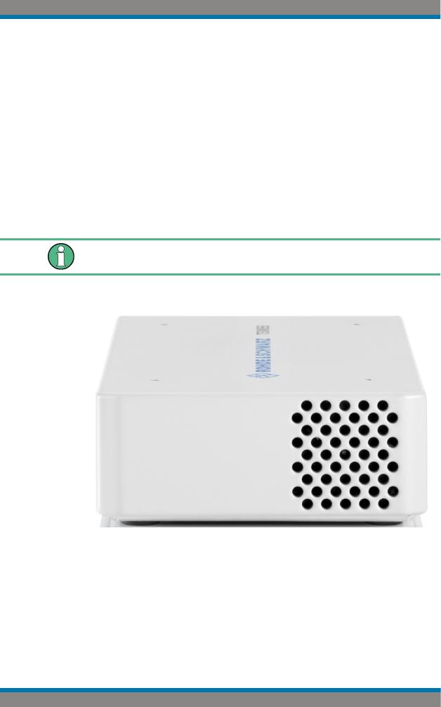
Front Panel View |
|
The front panel of the R&S TSME6 does not provide any connectors or control ele- |
|
ments for operation. |
Behind the right side of the rear panel (with the ventilation openings), 4 status LEDs are located. These LEDs display the following states:
● LEDs ON: R&S TSME6 ready for operation, RF-PLLs initialized correctly ● LEDs OFF: R&S TSME6 is off or RF-PLLs initialized not correctly
If the fans are off (temperature on the controller board < 60° C), the LEDs are partially covered by the fan blades.
Figure 3-1: R&S TSME6 - front panel
User Manual 4900.0033.02 ─ 04 |
8 |

R&S®TSME6 |
Instrument Tour |
|
Rear Panel View |
|
|
Instrument damage caused by cleaning agents
Cleaning agents contain substances such as solvents (thinners, acetone, etc.), acids, bases, or other substances. Solvents can damage the front panel labeling, plastic parts, or screens, for example.
Never use cleaning agents to clean the outside of the instrument. Use a soft, dry, lintfree dust cloth instead.
3.2 Rear Panel View
This figure shows the rear panel view of the R&S TSME6. The individual elements are described in more detail in the subsequent sections.
Figure 3-2: R&S TSME6 - rear panel
1 = Power ON/OFF
2 = GPS antenna connector
3 = AUX connector
4 = LAN connector with LEDs
5 = DC IN connector
6 = RF IN connector (50 Ω)
7 = Pwr./State LEDs
Power ON/OFF
The On/Off key switches the device on and off if power is supplied via the DC IN connector. For details, see Chapter 5.3, "Switching the Instrument On and Off",
on page 35.
GPS antenna connector
An SMA connector is provided for the supplied external active GPS antenna (antenna power: 3 V, max. 25 mA).
User Manual 4900.0033.02 ─ 04 |
9 |

R&S®TSME6 |
Instrument Tour |
|
Rear Panel View |
The integrated multi-GNSS (GPS / BeiDou / Galileo / GLONASS) receiver allows to use three satellite systems in parallel. This offers an accuracy improvement of 30 % to 50 % by using a second constellation of satellites.
Following combinations are allowed:
● GPS only
● GPS / GLONASS / Galileo ● GPS / BeiDou
The R&S TSME6 can perform untethered dead reckoning in tunnels to provide position information even if no satellites are available. The untethered dead reckoning is performed in the device itself by built-in electronic gyroscopes.
For enabling untethered dead reckoning, see Chapter 5.1.8, "Enabling Untethered Dead Reckoning ", on page 28.
Depending on the intended use, the respective valid regulations regarding lightning protection of the antennas and regarding vehicle installation must be observed during installation.
AUX connector
The AUX connector can be used to connect additional devices, such as a signal generator that provides an external reference frequency for the R&S TSME6, or a synchronization cable for multiple R&S TSME6 connected to one host PC.
LAN connector with LEDs
The LAN connector provides a high-speed Gigabit Ethernet interface with an RJ 45 connector using IPv4. It is required to connect the R&S TSME6 to a host PC.
The LEDs on the LAN connector indicate the status of the connection to the host PC. LED 1 is on the left side of the connector, LED 2 is on the right.
Table 3-1: LAN LED 1 states and their meaning
LED state |
Description |
|
|
green |
Connection established |
|
|
green, blinking |
LAN sending or receiving, or identifying connected device |
|
|
Table 3-2: LAN LED 2 states and their meaning |
|
|
|
LED state |
Description |
|
|
off |
No connection |
|
|
yellow |
Physical connection established |
|
|
yellow, blinking |
Identifying connected device |
|
|
DC IN connector
The DC IN connector is required for the DC power supply (10-28 V, max. 1.8 A). For details, see Chapter 5.1.4, "Connecting the DC Power Supply", on page 20.
User Manual 4900.0033.02 ─ 04 |
10 |
R&S®TSME6 |
Instrument Tour |
|
Rear Panel View |
|
RF IN connector (50 Ω) |
|
The optional multi-band RF antenna (700 MHz to 2.6 GHz) or the device providing the |
|
RF signal is connected to the instrument's RF INPUT via a cable equipped with an |
|
appropriate connector (SMA female, 50 Ω input impedance, VSWR type 2.0). |
|
|
Risk of instrument damage
Do not overload the maximum allowed input of 20 dBm. Non-compliance will destroy the input mixer.
Depending on the intended use, the respective valid regulations regarding lightning protection of the antennas and regarding vehicle installation must be observed during installation.
Pwr./State LEDs
Table 3-3: POWER and STATE LED states and their meaning
STATE LED |
POWER LED |
Meaning |
|
|
|
off |
off |
no power supply connected at DC IN |
|
|
power supply off |
|
|
power supply < 10 V |
|
|
|
off |
yellow |
standby |
|
|
|
off |
green, blinking (2 Hz) |
FGPA configuration in progress |
|
|
|
red |
green |
FPGA configuration finished, preparing for start |
(up to 5 seconds |
|
|
during startup) |
|
|
|
|
|
off |
green |
R&S TSME6 ready, not connected |
|
|
|
green |
green |
connected |
|
|
|
green, blinking rap- |
green |
measuring |
idly |
|
|
|
|
|
green, blinking 2 Hz |
green |
Instrument is identified by the software |
|
|
|
red, blinking 2 Hz |
green |
temperature warning (controller board temperature = |
|
|
75° C ... 80° C) |
|
|
|
red (continuous) |
green |
temperature error (controller board temperature above |
|
|
80° C) |
|
|
|
*The fans are temperature-controlled and below a temperature of 60° C on the controller board, the fans are in status OFF.
User Manual 4900.0033.02 ─ 04 |
11 |

R&S®TSME6 |
Option Concept |
|
Technology Options |
4 |
Option Concept |
|
|
|
The R&S TSME6 scanner consists of the R&S TSME6 hardware as well as a set of |
||
|
(specified) technology and band options when it comes from the factory. |
||
4.1 |
Technology Options |
|
|
|
Technology options allow the R&S TSME6 to scan the input based on a specific tech- |
||
|
nology, for example, LTE. All technology options can be installed on the same instru- |
||
|
ment; the R&S TSME6 can measure various technologies simultaneously. |
||
|
Following technology options are available (for current availabilities see http:// |
||
|
www.rohde-schwarz.com/product/TSMx.html): |
||
|
Table 4-1: Available R&S TSME6 technology options |
||
|
|
|
|
|
Options |
Order number |
Description |
|
|
|
|
|
R&S TSME6-K10 |
4900.2459.02 |
R&S TSME6 scanner option: Block IQ |
|
|
|
|
|
R&S TSME6-K21 |
4900.2188.02 |
R&S TSME6 scanner option: WCDMA |
|
|
|
|
|
R&S TSME6-K22 |
4900.2165.02 |
R&S TSME6 scanner option: CDMA2000 |
|
|
|
|
|
R&S TSME6-K23 |
4900.2194.02 |
R&S TSME6 scanner option: GSM |
|
|
|
|
|
R&S TSME6-K24 |
4900.1242.02 |
R&S TSME6 scanner option: 1xEV-DO Rev. A |
|
|
|
|
|
R&S TSME6-K25 |
4900.2242.02 |
R&S TSME6 scanner option: CW |
|
|
|
|
|
R&S TSME6-K26 |
4900.2142.02 |
R&S TSME6 scanner option: TETRA |
|
|
|
|
|
R&S TSME6-K27 |
4900.2120.02 |
R&S TSME6 scanner option: RF-Power Scan |
|
|
|
|
|
R&S TSME6-K28 |
4900.2136.02 |
R&S TSME6 scanner option: WiMAX™ |
|
|
|
|
|
R&S TSME6-K29 |
4900.2171.02 |
R&S TSME6 scanner option: LTE |
|
|
|
|
|
R&S TSME6-K30 |
4900.2113.02 |
R&S TSME6 scanner option: LTE MIMO 2x2,4x2,4x4 |
|
|
|
|
|
R&S TSME6-K32 |
4900.2288.02 |
R&S TSME6 scanner option: LTE eMBMS |
|
|
|
|
|
R&S TSME6-K34 |
4900.2207.02 |
R&S TSME6 scanner option: NB-IoT/Cat NB1-Scan- |
|
|
|
ning |
|
|
|
|
|
R&S TSME6-K35 |
4900.2465.02 |
R&S TSME6 scanner option: LTE M |
|
|
|
|
|
R&S TSME6-K40 |
4900.2259.02 |
R&S TSME6 Automatic Channel Detection (ViCom |
|
|
|
only, not for R&S ROMES) |
|
|
|
|
|
R&S TSME6-K50 |
4900.2436.02 |
R&S TSME6 scanner option: 5G NR scanning |
|
|
|
|
|
R&S TSME6-K80 |
4900.2442.02 |
pR&S TSME6 scanner option: BTS PE Enabler |
|
|
|
|
User Manual 4900.0033.02 ─ 04 |
12 |

R&S®TSME6 |
Option Concept |
|
Option Sharing Concept |
4.2 Band Options
The R&S TSME6 hardware simultaneously measures in all wireless communications bands from 350 MHz to 6 GHz. Using band licenses, more cost-efficient configurations are available for applications where only a limited number of bands need to be measured simultaneously.
These configurations limit the number of bands that can be measured in parallel. You can reconfigure the bands for each measurement as desired. Upgrade options are available to increase the bandwidth of the R&S TSME6 from a limited number of bands to full bandwidth. Following band options are available:
Table 4-2: Available R&S TSME6 band options
Options |
Order number |
Description |
|
|
|
R&S TSME6-KAB |
4900.2107.02 |
All bands measured simultaneously |
|
|
|
R&S TSME6-K1B |
4900.2094.02 |
1 band measured simultaneously |
|
|
|
R&S TSME6-K2B |
4900.2088.02 |
2 bands measured simultaneously |
|
|
|
R&S TSME6-K3B |
4900.2071.02 |
3 bands measured simultaneously |
|
|
|
R&S TSME6-K4B |
4900.2065.02 |
4 bands measured simultaneously |
|
|
|
R&S TSME6-K5B |
4900.2059.02 |
5 bands measured simultaneously |
|
|
|
R&S TSME6-KUB |
4900.2307.02 |
Upgrade: 1 additional band measured simultaneously |
|
|
|
The R&S TSME6 band assignment can be reconfigured by the user (see Chapter 6.1.4, "Configuring Measurement Bands - "Band Configuration"", on page 46).
For an overview of available cellular bands and their characteristics see Chapter A, "Available Cellular Bands", on page 62.
4.3 Option Sharing Concept
Definition TSME Group
A group of TSMEs are all TSME or TSME6 receivers, which are loaded by a TSME Admin (independent of their synchronization).
Technology Options
As soon as a technology option is valid on at least one TSME or TSME6 of the group, it is allowed to perform measurements on all connected receivers for this technology in the allowed frequency bands of the respective receiver.
User Manual 4900.0033.02 ─ 04 |
13 |

R&S®TSME6 |
Option Concept |
|
Option Sharing Concept |
|
Allowed Frequency Bands |
|
An "All Band Option" (KAB) allows to measure the complete frequency band supported |
|
by the hardware. On a TSME6, the complete frequency band is slightly larger than on |
|
a TSME. |
|
If there is no "All Band Option" (KAB) in a receiver, but only a non-empty set of band |
|
options for 1 to 5 bands (K1B, ... K5B) each, then the upper limited number of bands |
|
can be selected from a table for this receiver, which are then allowed for all measure- |
|
ments. |
|
The number of bands to be measured simultaneously is the sum of all activation num- |
|
bers x from valid KxB options with a maximum of 5. |
|
Example: |
|
If two K1B and one K2B are installed on a TSME6, then it is permitted to measure in 4 |
|
bands simultaneously for this TSME6. |
|
Special Scenario: MIMO |
|
If a K300 is installed on a TSME or TSME6, then a measurement for technology option |
|
index 130 (LTE MIMO) can be made on this TSME or TSME6 on all frequencies sup- |
|
ported by the hardware. |
|
The 5G NR FR2 demodulation with several TSME6 is also supported. |
User Manual 4900.0033.02 ─ 04 |
14 |
R&S®TSME6 |
Preparing for Use |
|
|
Putting into Operation |
|
5 Preparing for Use |
|
|
● |
Putting into Operation............................................................................................. |
15 |
● |
Connecting Multiple R&S TSME6s to One Host PC............................................... |
29 |
● |
Switching the Instrument On and Off...................................................................... |
35 |
● |
Connecting the R&S TSME6 to a Software Application for the First Time.............. |
35 |
5.1 Putting into Operation
This section describes the basic steps to be taken when setting up the R&S TSME6 for the first time.
Risk of injury due to disregarding safety information
Observe the information on appropriate operating conditions provided in the data sheet to prevent personal injury or damage to the instrument. Read and observe the basic safety instructions provided with the instrument, in addition to the safety instructions in the following sections. In particular:
●Do not use an isolating transformer to connect the instrument to the AC power supply.
●Do not open the instrument casing.
Risk of instrument damage due to inappropriate operating conditions
Specific operating conditions are required to ensure accurate measurements and to avoid damage to the instrument. Observe the information on appropriate operating conditions provided in the basic safety instructions and the instrument's data sheet.
Instrument damage caused by electrostatic discharge
Electrostatic discharge (ESD) can damage the electronic components of the instrument and the device under test (DUT). Electrostatic discharge is most likely to occur when you connect or disconnect a DUT or test fixture to the instrument's test ports. To prevent electrostatic discharge, use a wrist strap and cord and connect yourself to the ground, or use a conductive floor mat and heel strap combination.
User Manual 4900.0033.02 ─ 04 |
15 |
R&S®TSME6 |
Preparing for Use |
|
Putting into Operation |
|
|
Risk of instrument damage during operation
An unsuitable operating site or test setup can cause damage to the instrument and to connected devices. Ensure the following operating conditions before you switch on the instrument:
●The instrument is dry and shows no sign of condensation.
●The instrument is positioned as described in the following sections.
●Signal levels at the input connectors are all within the specified ranges.
EMI Suppression
Electromagnetic interference (EMI) may affect the measurement results.
To suppress generated electromagnetic interference (EMI):
●Use only double shielded cables for RF and GPS connection when not using the standard accessory.
●Always terminate open cable ends.
●DC-based lab networks are not allowed to be used for power supply.
●LAN cable length to the next PC or switch must be < 30m.
●Note the EMC classification in the data sheet.
● Unpacking and Checking the Instrument................................................................ |
16 |
|
● |
Accessory List......................................................................................................... |
17 |
● |
Cascading R&S TSME6s........................................................................................ |
17 |
● Connecting the DC Power Supply........................................................................... |
20 |
|
● Setting Up the LAN Connection to the Host PC...................................................... |
22 |
|
● |
Connecting External Devices.................................................................................. |
27 |
● Connecting a Kensington Lock............................................................................... |
28 |
|
● Enabling Untethered Dead Reckoning ................................................................... |
28 |
|
5.1.1 Unpacking and Checking the Instrument
Check the equipment for completeness using the delivery note and the accessory lists for the various items. Check the instrument for any damage. If there is damage, immediately contact the carrier who delivered the instrument. Make sure not to discard the box and packing material.
Packing material
Retain the original packing material. If the instrument needs to be transported or shipped later, you can use the material to protect the control elements and connectors.
User Manual 4900.0033.02 ─ 04 |
16 |

R&S®TSME6 |
Preparing for Use |
|
Putting into Operation |
5.1.2 Accessory List
The instrument comes with the following accessories:
●Printed Getting Started manual
●LAN cable
●GPS antenna
●12 V DC power supply cable (cigarette lighter cable)
●4 connecting screws
5.1.3Cascading R&S TSME6s
Rackmounting
The R&S TSME6 can be installed in a 19 inch rack using a rack adapter kit for one to four R&S TSME6s (option R&S TSME6-Z2, R&S no. 4900.1030.02). The installation instructions are part of the adapter kit.
Figure 5-1: Rackmounting of 2 R&S TSME6s
Figure 5-2: Rackmounting of 2 R&S TSME6s (reverse orientation of R&S TSME6s)
User Manual 4900.0033.02 ─ 04 |
17 |

R&S®TSME6 |
Preparing for Use |
|
Putting into Operation |
Figure 5-3: Rackmounting of 4 R&S TSME6s
Figure 5-4: Rackmounting of 4 R&S TSME6s (reverse orientation of R&S TSME6s)
Risk of instrument damage due to overheating
An insufficient airflow can cause the instrument to overheat, which may disturb the operation and even cause damage. Make sure that all fan openings are unobstructed and that the airflow perforations are unimpeded, particularly when the instrument is installed in a rack or packed in a backpack. The R&S TSME6 draws in fresh air from the front pane and warm air flows out at its panes. Thus, if no active cooling is installed, ensure that the following surrounding spaces to the instrument are kept clear:
●Front pane: minimum 2 cm
●Left/right panes: minimum 1 cm
Other mounting options
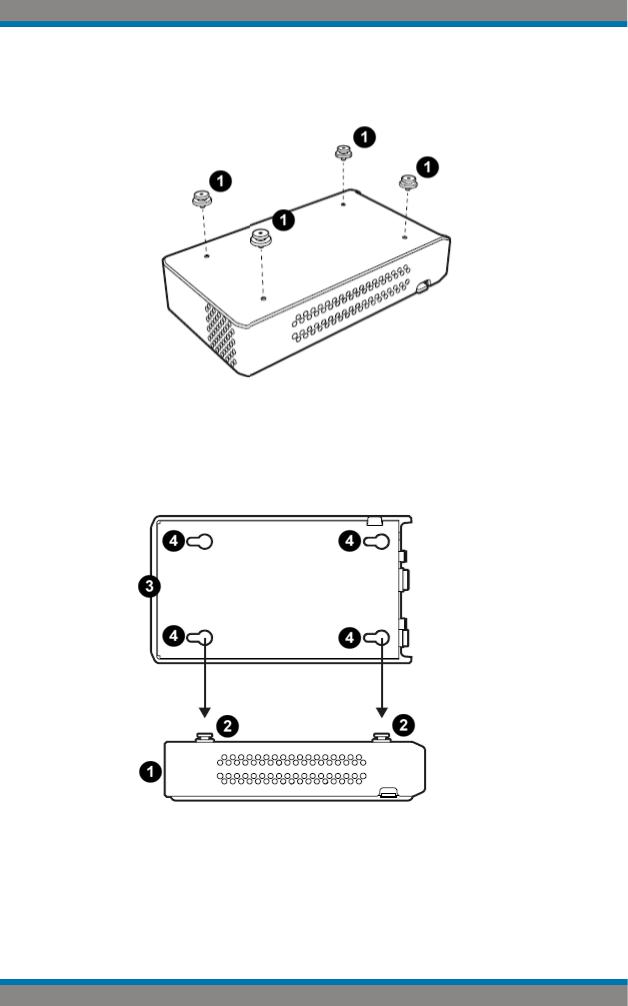
To connect two R&S TSME6 devices directly, perform the following steps.
1.Screw the connecting elements (R&S No. 4900.0804.00) on the top of the R&S TSME6.
User Manual 4900.0033.02 ─ 04 |
18 |
R&S®TSME6 |
|
Preparing for Use |
|
|
Putting into Operation |
|
● |
Torque: 0.66 Nm ± 0.05 Nm |
|
● |
Secure with liquid plastic |
Figure 5-5: Connecting elements
1 = Connecting elements (R&S No.4900.0804.00)
2.Align the connecting elements with the holes on the bottom of a second R&S TSME6 and press the R&S TSME6 down.
Figure 5-6: Aligning R&S TSME6s
1 = 1st R&S TSME6
2 = Connecting screws
3 = 2nd R&S TSME6
4 = Holes on the bottom pane of R&S TSME6
User Manual 4900.0033.02 ─ 04 |
19 |

R&S®TSME6 |
Preparing for Use |
|
Putting into Operation |
|
3. Push the 1st R&S TSME6 to the front until the mechanism locks. |
|
To disconnect the R&S TSME6, lift the release button on the pane of the upper R&S |
|
TSME6 and slide it until the device is released. |
Figure 5-7: Disconnect two R&S TSME6s
1 = Release button
5.1.4 Connecting the DC Power Supply
The DC power supply connector is on the rear panel of the unit. Voltages from 10 V to 28 V are supported. There is no need to set the used voltage manually.
Possible power cable connections
The R&S TSME6 can work with the following DC power supplies:
●Cigarette lighter power supply (for example in a vehicle) using the supplied DC power cable
●Optional AC power supply and power cable R&S TSME6-Z1 (see )
●Proprietary power supply with an adapted power cable
Using the supplied cigarette lighter power supply cable
►To use the power supply from a cigarette lighter, connect the supplied power cable from the R&S TSME6 to the cigarette lighter.
User Manual 4900.0033.02 ─ 04 |
20 |
R&S®TSME6 |
Preparing for Use |
|
Putting into Operation |
Connecting a proprietary power supply
►To use a proprietary DC supply with the R&S TSME6 power cable, demount the cigarette lighter adapter from the supplied power cable and connect the open ends of the cable to the proprietary power supply. Be sure to respect the correct polarity (see Figure 5-8).
Figure 5-8: Supplied power cable with cigarette lighter adapter
Danger of shock!
To avoid a shock hazard and instrument damage, note the following:
●After moisture condensation, allow the instrument to dry before switching on.
●The instrument is still power-supplied while it is in standby mode, that is, with the power button switched off, but still connected with the DC power supply.
●After connecting the power supply, the instrument is immediately under power.
●The supplied DC connector is intended for disconnection.
●If any DC supply other than R&S TSME6-Z1 is used:
–The DC supply must be in accordance with IEC / EN / UL / CSA 60950-1 or IEC / EN / UL / CSA EN EN61010-1.
–Use only Safety Extra Low Voltage (SELV) power supplies
–Observe the DC input range of 10 V to 27 V with maximum of 1.8 A (inrush current)
–The 12 V vehicle cigarette lighter socket must be fused
User Manual 4900.0033.02 ─ 04 |
21 |
Loading...