


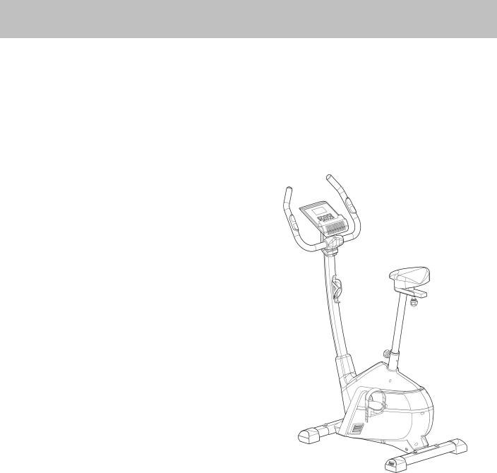
Roger Black Gold Bike
Assembly & User’s Instructions- Please Keep for future reference |
|
402/6004 |
Important – Please read these instructions fully before assembly or use
These Instructions contain important information which will help you get best from your equipment and ensure safe and correct assembly, use and maintenance.
If you need help or have damaged or missing parts, call the Customer Helpline: 0345 600 1714
Issue 1 -4/18/14
Contents
|
|
|
|
|
|
Safety Information |
2 |
|
Components - Parts |
3 |
|
Components – Fixings |
4 |
|
Assembly Instructions |
5-11 |
|
Computer Operation |
12-19 |
|
Exercising Information |
20-23 |
|
* Before Starting |
20 |
|
* Muscle Chart |
21 |
|
* Warming up and Cooling down |
22-23 |
|
Care and Maintenance |
24 |
|
Exploded Parts Diagram |
25 |
|
Parts List |
26 |
|
Guarantee |
|
|
|
|
|
1

Safety Information
Important – Please read fully before assembly or use
To reduce the risk of serious injury, read the entire manual before you assemble or operate the Roger Black Bike. In particular, note the following safety precautions:
Assembly
•Check you have all the components and tools listed on pages 3 and 4, bearing in mind that, for ease of assembly, some components are pre-assembled.
•Keep children and animals away from the work area, small parts could choke if swallowed.
•Make sure you have enough space to layout the parts before starting.
•Assemble the item as close to its final position (in the same room) as possible.
•This equipment must be built and used on a stable and level surface.
•Dispose of all packaging carefully and responsibly.
Using
•Keep unsupervised children away from the equipment.
•Injuries to health may result from incorrect or excessive training.
•It is the responsibility of the owner to ensure that all users of this product are properly informed as to how to use this product safely.
•This product is intended for domestic use only.
Do not use in any commercial, rental, or institutional setting.
• Before using the equipment to exercise, always do stretching exercises as part of a proper warm up.
• If the user experiences dizziness, nausea, chest pain, or other abnormal symptoms stop the workout and seek immediate medical attention.
•Only one person at a time should use the equipment.
•Keep hands away from all moving parts.
•Always wear appropriate workout clothing when exercising. Do not wear loose or baggy clothing, as it may get caught in the equipment. Wear trainers to protect your feet while exercising.
•Do not place any sharp objects around the equipment.
•Disabled persons should not use the equipment without a qualified person or doctor in attendance.
•This product is suitable for a maximum user weight of: 125kgs.
•This product conforms to: BS EN ISO 20957-1 and BS EN957-5 Class (H) - Home Use - Class (C).
•The braking system is adjustable.
Battery safety
•Warning: Incorrect installation of batteries may cause battery leakage and corrosion, resulting in damage to the computer.
•Do not mix old and new batteries, or batteries of different types.
•Do not dispose of batteries in a fire.
•Do not dispose of batteries with
normal household waste, take to a local recycling center.
Warning: Before beginning any exercise program, consult your doctor. This is especially important for persons over the age of 35 or persons with pre-existing health problems. You MUST read all instructions before using any fitness equipment. Argos and its associates assume
no responsibility for personal injury or property damage sustained by or through the use of this product.
Warning! Heart rate monitoring systems may be inaccurate. Over exercising may result in serious injury or death. If you feel faint stop exercising immediately. For the most accurate heart rate measure, please hold both hand pulse sensors continuously during this programme. The pedal crank training equipment is not suitable for therapeutic purposes.
2
Components |
- |
Parts |
the Customer Helpline: 0345 600 1714. |
|
|
|
If you have damaged or missing parts, please call |
|
|
|
|
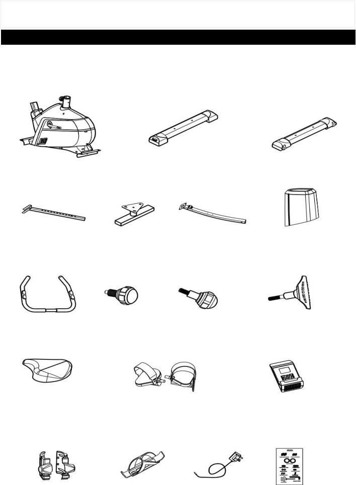
Please check you have all parts listed below
Note: Some of the smaller components may be pre-fitted to larger components. Please check carefully before contacting Argos regarding any missing components.
Total mass of the product is 26kg. Footprint of the product is 98.5cm × 54cm.
|
|
2. Rear Stabilizer |
|
3. Front Stabilizer |
1. Main Frame |
|
|
||
|
|
|
|
|
|
|
|
|
|
4. Seat Post |
5. Seat Adjustment Bracket |
|
6. Front Post |
33. Front Post Cover |
|
|
|
|
|
|
|
|
|
|
7. Handle |
8. M16 Lock Knob |
9. M10 Lock Knob |
|
10. M8 T Lock Knob |
|
|
|
|
|
11. Saddle |
|
12. Pedal (Left/Right) |
|
|
|
|
13. Computer |
||
|
|
|
|
|
|
|
|
|
|
15. Handle Cover (L/R) |
16. Bottle Holder |
68. Charger |
Hardware Pack |
|
|
|
|
3

Components - Fixings
Please check you have all parts listing below
Note: Please check carefully before contacting Argos regarding any missing fixings.
17 |
18 |
|
19 |
|
|
|
|
|
M10x20mm Allen Bolt × 4 |
|
10mm Spring Washer × 4 |
|
10mm Washer × 4 |
|||
|
|
|
|
|
|
|
|
|
|
|
|
|
|
|
|
|
|
|
|
|
|
|
|
23 |
|
|
21 |
|
|
22 |
|
|
|||
|
|
|
|
|
|
|
|
|
|
|
|
|
|
|
|
|
|
|
|
|
|
|
|
|
|
|
|
|
8mm Washer × 2 |
|
|
8mm Spring Washer × 4 |
|
M8x15mm Allen Bolt × 4 |
|
|
|
|
|
|
|
|
|
|
|
|
|
|
|
|
|
|
|
|
|
|
|
|
|
|
74 |
|
|
|
|
|
|
|
|
||
|
|
|
|
34 |
|
|||
24 |
|
|
|
|
||||
|
|
|
|
|
|
|
|
|
|
|
|
|
|
|
|
|
|
8mm Arc Washer × 2 |
|
|
|
Joint Ring × 2 |
|
ST4.2x15mm Philips Screw × 2 |
|
||
|
|
|
|
|
|
|
|
|
|
5mm Allen Wrench × 1 |
|
6mm Allen Wrench × 1 |
|
Multi Wrench × 1 |
|
|
|
|
|
|
|
|
|
|
|
|
|
|
|
4

Assembly Instructions
17
18
17
19
18
19
3 |
1 |
|
|
30
2
30
Step 1
A.Attach Front Stabilizer (3) to Main Frame (1) using 2 x M10x20MM Allen bolts (17), 2 x10MM Spring Washers (18) and 2 x10MM Washers (19).
B.Attach Rear Stabilizer (2) to Main Frame (1) using 2 x M10x20MM Allen bolts (17), 2 x10MM Spring Washers (18) and 2 x10MM Washers (19).
Note: The knob on the Level Feet (30) can be rotated to ensure the bike sit flat on the ground as shown in the diagram. Turn it anti clockwise to increase height and turn it clockwise to decrease height.
5

Assembly Instructions
6
|
33 |
23 22 |
24 |
23 |
2122 23 |
22 24 |
23 22 21
1
1
Step 2
A.Place the Front Post (6) through the Front Post Cover (33).
B.Bring the main Wire out from front tube of Main Frame (1) and connect it with the Wire from the bottom of the Front Post (6).
C.Fix the Front Post (6) to the Main Frame (1) and tighten with 4 x M8x15MM Allen bolts (23), 4 x 8MM Spring Washers (22), 2 x 8MM Washers (21) and 2 x 8MM Arc Washers (24).
6
Assembly Instructions
13
71
71
16
34
34
6
12R
12L
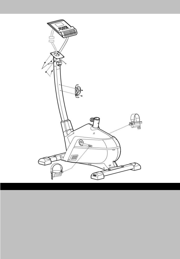
Step 3
A.Thread the two cables from the computer (13) into the top of the Front Post (6); connect the Wire from Computer (13) to the Wire from Front Post (6).
B.Attach the Computer (13) to the Front Post (6) using 4 x M5x8MM Dome Head Philips Bolt (71). Note: Part (71) is pre-assembled.
C.Attach the Bottle Holder (16) to the Front Post (6) using 2 x MT4.2x15mm Philips Screws (34).
D.Attach the Left Pedal (12-L) to the crank with “L” of the Main Frame (1) and tighten it. Please note this must be threaded anti clockwise. Attach the pedal strap to the left pedal as the diagram shows.
E.Attach the Right Pedal (12-R) to the crank with “R” of the Main Frame (1) and tighten it. This must be threaded clockwise. Attach the pedal strap to the right pedal as the diagram shows.
Note: Adjust the tension of pedal strap as your requested.
7

Assembly Instructions
15R
15L
25
74
25
25 |
|
|
74 |
10 |
|
7 |
||
|
||
25 |
|
6
Step 4
A. Attach the Handle (7) to the bracket on the Front Post (6), and secure with M10 Lock knob (10).
Note: To adjust the position of the handle, turn the lock knob (10) anti clockwise to loose the handle (7) as shown in the diagram, and adjust the handle (7) to your required position, then secure the lock knob (10).
B.Connect the two signal Wires from Front Post (6) to the two Wires from Handle (7).
C.Put the Left Handle Cover (15-L) and Right Handle Cover (15-R) into the left and right side of the Handle (7) respectively, and then lock them to Front Post (6) using 4 x ST4.2x15mm Philips Screw (25). Please note that the 4 × ST4.2 × 15mm Philips Screw (25) are pre-assembled.
D.Put two Joint Rings (74) into the left and right side of the Handle (7) respectively, and then tuck them in the corresponding holes from two sides of the Left & Right Handle Cover (15L, 15R).
8
 Loading...