

Page 1
Issue 1 -3/15/15
These instructions contain important information which will help you get the best from your
equipment and ensure safe and correct assembly, use and maintenance.
If you need help or have damaged or missing parts, call the Customer Helpline: 0345 600 1714
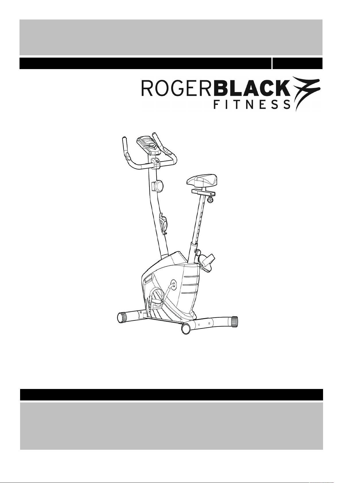
Roger Black Plus Exercise Bike
Assembly & User Instructions- Please Keep for future reference
404/8800
Important –
Please read these instructions fully before assembly or use
Page 2
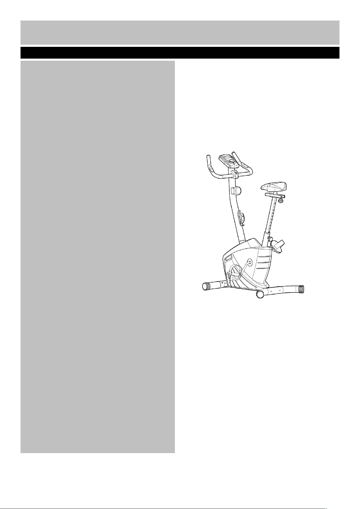
Contents
Safety Information
2
Components - Parts
3
Components – Fixings
4
Assembly Instructions
5-9
Free area and training area
Computer Operation
11-12
Exercising Information
13-16
* Before Starting to exercise
13
* Muscle Chart
14
* Warming up and Cooling down
15-16
Care and Maintenance
17
Exploded Parts Diagram
18
Parts List
19
Guarantee
1
10
Page 3

、
To reduce the risk of serious injury, read the entire manual before you assemble or operate the Roger Black
Plus Bike. In particular, note the following safety precautions:
Assembly
• Check you have all the components and tools
listed on pages 3 and 4, bearing in mind that, for
ease of assembly, some components are
pre-assembled.
• Keep children and animals away from the work
area, small parts could pose a choking hazard if
swallowed.
• Make sure you have enough space to layout the
parts before starting.
• Assemble the item as close to its final position
(in the same room) as possible.
• The bike must be used on a stable and level
surface.
• Dispose of all packaging carefully and responsibly.
Using
• Keep unsupervised children away from the
equipment.
• Injuries to health may result from incorrect or
excessive training.
• It is the responsibility of the owner to ensure that
all users of this product are properly informed as to
how to use this product safely.
• This product is intended for domestic use only.
Do not use in any commercial, rental, or institutional
setting.
• Before using the equipment to exercise, always do
stretching exercises to properly warm up.
• If the user experiences dizziness, nausea, chest
pain, or other abnormal symptoms stop the
workout and seek immediate medical attention.
•Only one person at a time should use the
equipment.
• Keep hands away from all moving parts.
• Always wear appropriate workout clothing when
exercising. Do not wear loose or baggy clothing, as
it may get caught in the equipment. Wear trainers
to protect your feet while exercising.
• Do not place any sharp objects around the
equipment.
• Disabled persons should not use the equipment
without a qualified person or doctor in attendance.
• This product is suitable for a maximum user weight
of: 125kgs.
• This product conforms to: BS EN ISO20957-1 and
BS EN957-5 Class (H) - Home Use - Class (C).
• The braking system is adjustable.
Battery safety
·
Warning: Incorrect installation of batteries
may cause battery leakage and corrosion,
resulting in damage to the computer.
· Do not
mix old and new batteries, or
batteries of different types.
·
Do not
dispose of batteries in a fire.
·
Do not
dispose of batteries with
normal household waste, take to a local recycling
centre.
Warning: Before beginning any exercise program, consult your Doctor. This is especially
important for persons over the age of 35 or persons with pre-existing health problems. You
MUST read all instructions before using any fitness equipment. Argos and its associates assumes
no responsibility for personal injury or property damage sustained by or through the use of this product.
Warning! Heart rate monitoring systems may be inaccurate. Over exercising may result in serious injury or
death. If you feel faint stop exercising immediately. The pedal crank training equipment is not suitable for
therapeutic purposes.
Important – Please read fully before assembly or using
Safety Information
2
Page 4
Note: Some of the smaller components may be pre-fitted to larger components. Please check carefully
before contacting Argos regarding any missing components.
Total mass of the product is 24kg. Footprint of the equipment is 91.5cm × 46cm.
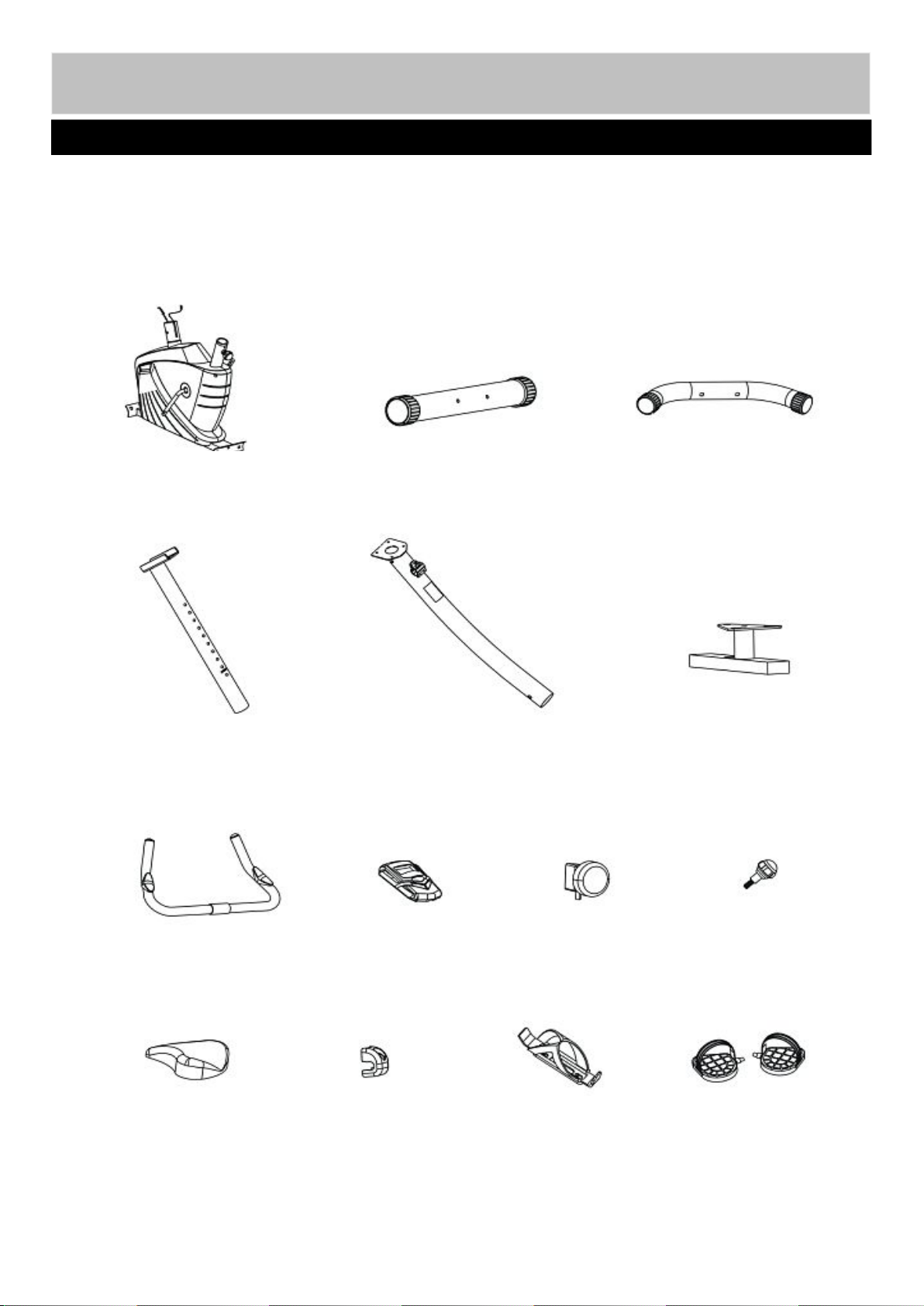
Components - Parts
If you have damaged or missing parts, please call
the Customer Helpline: 0345 600 1714.
Please check you have all parts listed below
3
1. Main Frame
2. Front Stabilizer
3. Rear Stabilizer
4. Seat Post
7. Front Post
5. Seat Adjustment Bracket
8. Handlebar
11. Computer
12. Tension Knob
22. M10 Lock Knob
29. Saddle
33. Handle Cover
46. Bottle Holder
48. Pedals (L/R)
Page 5
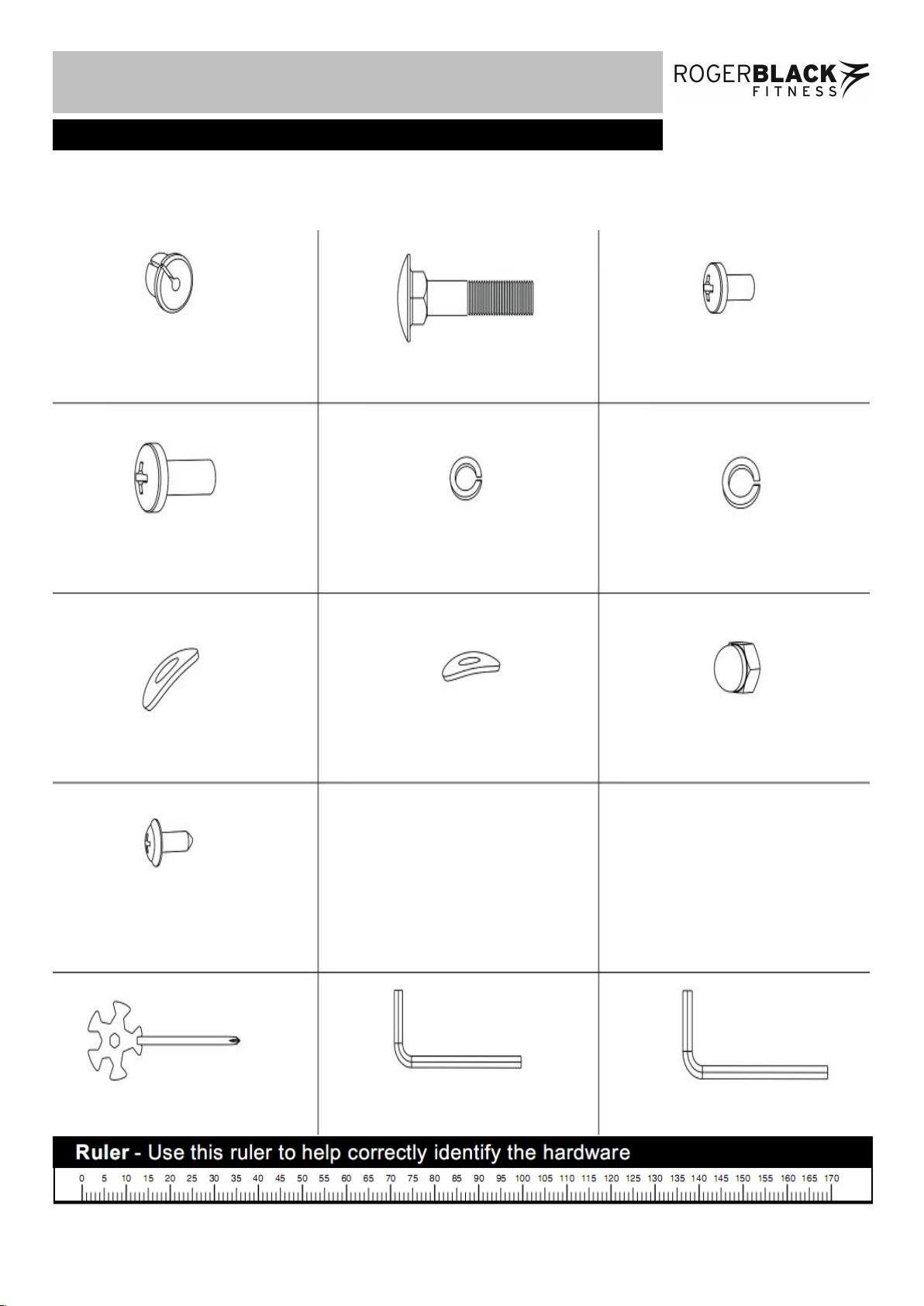
Note: Some of the fixings are pre-fitted to the larger components. Please check carefully before contacting
Argos regarding any missing fixings.
、
Components - Fixings
Please check you have all parts listed below
4
6mm Allen Key × 1
53
54
55
59
60
52
63
64
66
Ø13mm Wire Holder× 2
M10x75mm Carriage Bolt x 2
Φ10mm Spring Washer × 4
M10x20mm Allen Bolt × 2
Φ8mm Spring Washer × 4
Φ10xR33mm Arc Washer × 4
Φ8xR30mm Arc washer× 4
Multi Wrench × 1
M10 Dome Head Nut × 2
M8x15mm Allen Bolt × 4
71
ST4.8x15mm Dome Head
Philips Screw × 2
5mm Allen Key × 1
Page 6
Assembly Instructions
A. Attach Front Stabilizer (2) to the Main Frame (1) using 2 x M10 x 20mm Allen Bolts (55), 2 x Ø10mm
Spring Washers (60) and 2 x Ø10 x R33mm Arc Washers (63).
B. Attach Rear Stabilizer (3) to the Main Frame (1) using 2 x M10 x 75mm Carriage Bolts (53), 2 x Ø10 x
R33mm Arc Washers (63), 2 x Ø10mm Spring Washers (60) and M10 Dome Head Nut (66).
Note: The self Levelling Feet (19) can be rotated when pulling out to ensure the bike sits flat on the
ground.
Step 1
5
55
53
66
60
60
66
63
63
19
19
63
60
2
3
1
Page 7
Assembly Instructions
A. Connect the Sensor Wire C1 to C2.
B. Attach the Front Post (7) to the Main Frame (1) using 4 x M8x15mm Allen bolt (54), 4 x Φ8mm
Spring Washer (59) and 4 x Φ8xR30mm Arc Washer (64).
C. Remove the M5x50mm Philips Bolt and Washer (74) from the Tension Knob (12).
Note: The M5x50mm Philips Bolt and Washer (74) is pre-assembled to the Tension Knob (12).
D. Turn the Tension Knob (12) to Level 1 as shown (1) and connect the bottom of the tension knob with
the hook as shown (2). Then attach the Tension Knob (12) to the Front Post (7) using 1 x M5x50mm
Philips Bolt and Washer (74).
Step 2
6
59
12
7
54
64
59
54
59
64
64
54
C
1
C
2
1
D
2
D
1
D
1
D
2
D
1
D
2
54
64
59
74
Page 8

Assembly Instructions
A. Connect the Pedals (48 L&R) to Cranks (26 L&R) as shown.
Note: For the two foot pedals marked "L" and "R". Fasten the left pedal by turning anti-clockwise
and fasten the right pedal by turning clockwise. Attach the pedal straps to the pedals as shown in the
diagram, the tension for pedal strap can be adjusted by its hole position.
B. Connect Sensor Wire A1to A2, then pass the two handle Pulse Sensor Wires B1through the upper
openings of the Front Post (7).
C. Attach the Computer (11) onto the top of the Front Post (7) and tighten with 4 x M5x15mm Philips
bolts (73).
Note: The 4 x M5x15mm Philips Bolts (73) are pre-fitted on the back of the Computer (11).
Step 3
7
48R
48L773
26R
26L
A1
A2
11
B1
B1
Page 9

Assembly Instructions
A. Attach the Handle (8) to the Front Post (7) and tighten with 1 x M8x40 Allen Bolt (56), 1 x Φ8mm
Spring Washer (59), 1 x Φ8mm Washer (61).Then fit the L&R Handle Cover (33) onto the Front Post
(7). Please note that the handle can be adjusted to your required position.
Note: The M8x40 Allen bolt (56), Φ8mm Spring Washer (59) and Φ8mm Washer (61) are pre-fitted to
the Front Post (7).
B. Connect the two wires (B1&B2), then insert the 2 X Φ13mm Wire Holder (52) into the hole on the
Front Post (7) as shown.
C. Fix the Bottle Holder (46) onto the Front Post (7) with 2 x ST4.8x15mm Dome Head Philips Screw
(71).
Step 4
8
56
61
33
11
52
59
46
B
2
8
71
7
B
1
B1B
2
52
Page 10

-
A. Attach the Saddle (29) to the Seat Adjustment Bracket (5), and secure with 3 xΦ8mm Washers (75),
and 3 x M8mm Nuts (76).
Note: Φ8mm Washers (75) and Aircraft Nuts (76) are pre-fitted to Saddle (29) in the factory.
B. Attach the Seat Adjustment Bracket (5) to the Seat Post (4), and tighten with M10 Knob (22).
Note: Move the Saddle (29) forward or backward to a suitable position then tighten M10 Knob (22).
C. Insert the Seat Post (4) into the Main frame (1). Position the Seat Post (4) upward and downward at
your required and secure with the M16 Lock knob (21).
Step 5
9
Assembly Instructions
4
29
75
5
22
1
21
76
Page 11

The free area must be at least 0.6m greater than the training area in the directions from which the
equipment is accessed. The free area is a space should you need to dismount in an emergency. Where
two pieces of equipment are positioned adjacent to each other the value of the free area may be shared.
Free area and training area
0.6m
(Free area)
0.6m
(Free area)
0.6m
(Free area)
0.6m
(Free area)
Training area
1.2m
10
Page 12

MODE: Pressing Mode allows you to change the
display function on the console.
SET: Used to confirm your target time, distance,
pulse or calories.
RESET: Used to reset a value to zero.
1. AUTO ON/OFF
The system turns on when any key is pressed
or when you start pedalling.
The system turns off automatically when the
bike has detected no activity for 4 minutes.
2. RESET
The unit can be reset by either changing the
batteries or pressing the MODE key for 3
seconds.
3. MODE
The console will scan through the display
functions. If you want to lock the display to only
look at one function then press MODE when the
required function is flashing.
FUNCTIONS:
1. TIME: Press MODE until TIME is displayed.
Time will now be displayed during your workout.
2. SPEED: Press MODE until speed is displayed.
The current speed will now be displayed during
your workout.
3. DISTANCE: Press MODE until distance is
displayed. The distance will now be displayed
during your workout.
4. CALORIE: Press MODE until Calorie is
displayed. The number of calories burnt will now
be displayed during your workout.
5. ODOMETER: If applicable to your model, press
MODE until odometer is displayed. This will then
show the total distance cycled with this product
since last reset.
6. PULSE: If applicable to your model, press MODE
until pulse is displayed. The user's heart rate in
beats per minute will be displayed during your
workout if holding the hand pulse sensors.
Ensure you wait for 30 seconds to get a reading.
SCAN: The display will change every 4 seconds,
scrolling through time, speed, distance, calories.
BATTERY:
If the display starts to fade, the batteries need
replacing.
Computer Operation
Functions and operations
11
Page 13

Specification
Function
Auto Scan
Every 4 Seconds
Speed
0.0 – 99.9 Km/h
Distance
0.0 – 999.9 Km
Time
0:00 – 99:59 (Minute: Second )
Calories
0.0 – 999.9 Cal
Odometer
0.0 – 999.9 Km
Pulse
40 – 240 BPM
Battery type
2 x SIZE – AA
10
Computer Operation
12
1. Remove the battery cover on the back of the
computer.
2. Replace 2x1.5V (AA) batteries.
3. Make sure the batteries are installed correctly
and the polarities are correct.
4. The battery life is approx. 10 months under
normal usage.
5. When the batteries are removed, all values
will reset to zero.
Replacing the batteries
Page 14

85% to Max
65% to 85%
55% to 65%
Up to 55%
How you begin your exercise program depends on your physical condition. If you have been inactive for
several years, or are overweight, you must start slowly and increase your time on the equipment;
a few minutes per workout increase is advisable.
Initially, you may be able to exercise only for a few minutes in your target zone, however, your aerobic fitness
will improve over the next six to eight weeks. Don’t be discouraged if it takes longer. It’s important to work
at your own pace.
Please remember these essentials:
• Have your doctor review your training and diet programs to advise you of a workout routine you should adopt.
• Begin your training program slowly with realistic goals that have been set by you and your doctor.
• Monitor your pulse frequently. Establish your target heart rate based on your age and condition.
• Set up your equipment on a flat even surface with adequate training area, as prescribed in this manual.
Exercise intensity
To maximize the benefits of exercising, it is important to exercise at an appropriate intensity. The intensity
level can be found by using your heart rate as a guide. For effective aerobic exercise, your heart rate should
be maintained at a level between 65% and 85% of your maximum heart rate as you exercise. This is known as
your target zone. You can find your target zone in the table below.
200
180
160
140
120
100
80
25 30 35 40 45 50 55 60 70
Age
During the first few months of your exercise program, keep your heart rate near the low end of your target zone
as you exercise. After a few months, your heart rate can be increased gradually until it is near the middle of
your target zone as you exercise.
To measure your heart rate, stop exercising but continue moving your legs or
walking around and place two fingers on your wrist. Take a six-second heartbeat
count and multiply the results by 10 to find your heart rate. For example, if your
six-second heartbeat count is 14, your head rate is 140 beats per minute.
(A six-second count is used because your heart rate will drop rapidly when you
stop exercising.) Adjust the intensity of your exercise until your heart rate is at the
required level.
Cardiovascular
performance
Intermediate aerobic
Effective fat burning
Exercising Information
Before starting your exercise
13
Beats per minutes (bpm)
Page 15

Aerobic Exercise
Aerobic exercise improves the fitness of your lungs and heart - your body’s most important muscle. Aerobic
exercise fitness is promoted by any activity that uses your large muscles (arms, legs, or buttock, for example).
Your heart beats quickly and you breathe deeply. An aerobic exercise should be part of your entire exercise
routine.
Weight Training
Along with aerobic exercising which helps get rid of and keep off the excess fat that our bodies can store,
weight training is an essential part of the exercise routine process. Weight training helps tone, build and
strengthen muscle. If you are working above your target zone, you may want to do a lower number of reps.
As always, consult your doctor before beginning any exercise program.
Targeted Muscle Groups
The exercise routine that is performed on this exercise bike will develop the upper and lower body
muscle groups. These muscle groups are highlighted on the muscle chart below.
Muscle Chart
14
Exercising Information
Page 16

Each workout should include the following three parts:
1. A warm-up, consisting of 5 to 10 minutes of stretching and light exercise. A proper warm-up
increases your body temperature, heart rate, and circulation in preparation for exercise.
2. Training zone exercise, consisting of 20 to 30 minutes of exercising with your heart rate in your training
zone. (Note: During the first few weeks of your exercise program, do not keep your heart rate in your
training zone for longer than 20 minutes.)
3. A cool-down, with 5 to 10 minutes of stretching. This will increase the flexibility of your muscles and will
help to prevent post-exercise problems.
Exercise Frequency
To maintain or improve your condition, plan three workouts each week, with at least one day of rest
between workouts. After a few months of regular exercise, you may complete up to five workouts each
week, if desired. Remember, the key to success is make exercise a regular and enjoyable part of your
everyday life.
Toe touch stretch
Stand with your knees bent slightly and
slowly bend forward from your hips.
Allow your back and shoulders to relax
as you reach down toward your toes as
far as possible.
Hold for 15 counts, then relax
Repeat 3 times.
Stretches: Hamstrings, back of knees and back.
Hamstring stretch
Sit with one leg extended. Bring the sole
of the opposite foot toward you and rest
it against the inner thigh of your
extended leg. Reach toward your toes
as far as possible.
Hold for 15 counts, then relax
Repeat 3 times for each
Stretches: Hamstrings, lower back and groin.
Warming up and Cooling down exercises
15
Exercising Information
leg.
Page 17

Inner thigh stretch
Calf/Achilles stretch
With one leg in front of the other, reach
forward and place your hands against a wall.
Keep your back leg straight and your back
foot flat on the floor. Bend your front leg,
lean forward and move your hips toward the
wall.
Hold for 15 counts, then relax.
Repeat 3 times for each leg. To cause
further stretching of the Achilles
tendons, bend your back leg as well.
Stretches: Calves, Achilles tendons and ankles.
Quadriceps stretch
With one hand against the wall for
balance, reach back and grasp one foot
with your other hand. Keeping your bent
knee pointing directly downward towards
the floor, gentle pull your
heel towards your buttock until you feel a gentle
stretch in the target area.
Hold for 15 counts, then relax.
Repeat 3 times .
Stretches: Quadriceps and hip muscles.
Sit with the soles of your feet together
and your knees outwards. Pull your feet
towards your groin area as far as
possible, and push your knee down
towards the ground.
Hold for 15 counts, relax.
Repeat 3 times.
Stretches: Quadriceps and hip muscles.
Exercising Information
16
leg.
Page 18

1. Examine the equipment
periodically in order to detect
any damage or.
The safety level of the
equipment can be maintained
only if it is examined regularly
for the damage and wear, e.g.
connection points.
2.
Lubricate moving parts with
light oil periodically to prevent
premature wear.
3.
Inspect and tighten all parts
before using the equipment,
Replace defective
components immediately and
keep the equipment out of use
until repair;
Special attention to
components most susceptible
to wear.
4. The equipment can be
cleaned using a damp cloth
and mild non-abrasive
detergent. Do not use
solvents.
5. Do not attempt to repair
this equipment yourself.
Should you have any difficulty
with assembly, operation or
use of your exercise product
or if you think that you may
have parts missing, contact
the manufacturer, their
approved service agent or the
Customer Helpline:
0345 600 1714.
Guarantee:
For guarantee purposes,
please retain your
purchase receipt.
Information for Users on Disposal of old Equipment and Batteries (European Union only)
These symbols indicate that equipment with these
symbols should not be disposed of as general
household waste. If you want to dispose of the product
or battery, please consider the collection systems or
facilities for appropriate recycling.
Notice: The sign Pb
below the symbol for
batteries indicates that
this battery contains
lead.
17
Care and Maintenance
Page 19

Exploded Parts Diagram
18
Page 20

Part
Description
QTY
Part
Description
QTY
1
Main frame
141Bearing Block
2
2
Front stabilizer
142C-shaped Lock Ring
1
3
Rear stabilizer
143Bearing
2
4
Seat Post
144Φ11.5xΦ1.5x40mm Spring
1
5
Seat Adjustment Bracket
145Axle
1
6
U-shaped bracket
146Bottle holder
1
7
Front Post
147Magnet
8
8
Handle
148Pedal (L/R)
1
9
Idle Wheel Bracket
149Φ12mm Bead Flange
4
10
Magnet bracket
150Φ9mm Bead Flange
1
11
Computer
151Φ12mm Spring Washer
2
12
Tension knob
152Φ13mm Wire Holder
2
13
Reduction Sleeve
153M10x75mm Carriage bolt
2
14
Φ20x Φ30 x 470 Handle grip
254M8x15mm Allen bolt
4
15
Handle pulse sensor
255M10x20mm Allen bolt
2
16
Φ25 x 1.5 End cap
256M8x40mm Allen bolt
1
17
40 x 20 x 1.5End cap
257M6x15mm Hex bolt
2
18
Transport Wheel
258M8x25mm Hex bolt
1
19
Level Foot
259Φ8mm Spring Washer
5
20
Φ75xΦ60x9mm Rubber Ring
160Φ10mm Spring Washer
6
21
M16 Lock knob
161Φ8mm Washer
2
22
M10 Knob
162Φ10mm Washer
2
23
Fly wheel
163Φ10xR33mm Arc washer
4
24
Alex164
Φ8xR30mm Arc washer
4
25
Belt Wheel
165M8 Nut
1
26
Crank (L/R)
166M10 Dome Head Nut
2
27
Belt167
M10 Hex Nut
2
28
Φ35mm Idle Wheel
168ST4.2x10mm Dome Head Philips
Screw
2
29
Saddle169
ST4.2x15mm Dome Head Philips
Screw
10
30
Spring170
ST4.8x15mm Dome Head Philips
Screw
4
31
Left cover
171ST4.8x15mm Dome Head Philips
Screw
2
32
Right cover
172ST4.2x20mm Dome Head Philips
Screw
2
33
Left & Right Handle Cover
173M5x15mm Philips Bolt
4
34
Crank Cover
274M5x50mm Philips Bolt
1
35
Wire Clip
275Φ8mm Washer
3
36
Reed Base
176M8 Nut
3
37
Lock Nut
1
A1/A2
1
38
C-shaped Lock Ring
1
B1/B2
2
39
Bead Flange
2
C1/C2
1
40
Ball Bearing
2
D1/D2/D3
1
Parts List
19
Page 21

Guarantee
Product Guarantee
This product is guaranteed against manufacturing defects from a period of
This product is guaranteed for twelve months from the date of original
purchase. Any defect that arises due to faulty materials or workmanship
will either be replaced, refunded or repaired free of charge where possible
during this period by the dealer from whom you purchased the unit.
The guarantee is subject to the following provisions:
• The guarantee does not cover accidental damage, misuse, cabinet parts,
knobs or consumable items.
• The product must be correctly installed and operated in accordance with
the instructions contained in this manual.
• It must be used solely for domestic purpose.
• The guarantee will rendered invalided if the products is re-sold or has been
damaged by inexpert repair.
• Specifications are subject to change without notice.
• The manufacturer disclaims any liability for the incidental or consequential
damages.
• The guarantee is in addition to, and does not diminish your statutory or
legal right.
• In the event of problem with the product with in the guarantee period call
Customer Helpline: 0345 600 1714
Guarantor: Argos Ltd
489 – 499 Avebury Boulevard
Central Milton Keynes
MK9 2NW
Year
 Loading...