

Rogerblack Gold Medal XT AG-14212 User Manual

Gold Medal XT
AG-14212
fit for life
with Roger Black

Dear Customer
We thank you for choosing your Roger Black Product and wish you every
success during your training.
Please read the User Manual and operation instructions carefully prior to
assembly and use, if you have questions please do not hesitate to contact us on
the following number or web site:
Customer service +44 (0) 0845 600 0464
Website www.rogerblackfitness.co.uk
E-mail
fitnessequipment.enquiries@argos.co.uk

Contents
Important Safety Instructions 2
Pre-assembly Notes 3
Assembly Steps 6
Computer Operation 11
Exploded Diagram 18
Parts List 20
Care & Maintenance 23
Stretching Routine 24
Limited Warranty 26
IMPORTANT SAFETY INSTRUCTIONS
Read all the instructions in this manual carefully before using your equipment
WA RNING: Before beginning this or any exercise programme, consult your physician. This is
especially important for persons who have not exercised regularly before or persons with
pre-existing health problems. Read all instructions before using. Manufacturer assumes no
responsibility for personal injury or property damage sustained by or through the use of this
equipment.
1. It is the responsibility of the owner to ensure that all users of this equipment are
adequately informed of all warnings and precautions.
2. Use the equipment only as described in this manual.
3. Place on a level and stable surface, with 2 meters of clearance around it. To protect the
floor or carpet from damage, place a mat under this equipment.
4. Keep the equipment indoors, away from moisture or dust. Do not put the equipment in a
garage, shed, outbuilding or covered patio, or near water. Failure to do this will invalidate
your warranty and could cause serious safety problems.
5. Do not operate the equipment where aerosol products are used or where oxygen is being
administered.
6. Keep children under the age of 12 and pets away from the equipment all the times.
7. The equipment should not be used by persons weighting more than 110kg. Serious injury
may occur if the user weight exceeds the limit shown here.
8. The equipment complies with class HC of the standard EN957.
9. Never allow more than one person on the equipment at a time.
10. Wear appropriate exercise clothing when using the equipment. Do not wear loose
clothing that could become caught in the equipment. Athletic support clothes are
recommended for both men and women.
11. If you feel pain or dizziness while exercising, stop immediately and cool down.
12. The pulse sensor is not a medical device. Various factors, including the user’s movement,
may affect the accuracy of the heart rate readings. The pulse sensor is intended only as
an exercise aid in determining heart rate trends in general.
13. This equipment is intended for home use only. Do not use in a commercial or institutional
setting.
STORE THESE INSTRUCTIONS IN A SAFE PLACE FOR FUTURE REFERENCE
PRE-ASSEMBLY NOTES
Open the Boxes
Make sure to inventory all of the parts that are included in the boxes. Check the
Hardware Chart for a full count of the number of parts included for proper assembly.
If you are missing any parts please call our Technical Support line
0845 600 0464
Gather Your Tools
Before starting the assembly of your unit, gather the necessary tools. Having all of
the tools at hand will save time and make the assembly quick and hassle-free.
Clear Your Work Area
Make sure that you have cleared away a large enough space to properly assemble
the unit. Make sure the space is free from anything that many cause injury during
assembly. After the unit is fully assembled, make sure there is a comfortable amount
of free area around the unit for unobstructed operation.
Hardware Chart
For your convenience, we have identified the hardware used in the assembly of this
product. This chart is provided to help you identify those items that may be unfamiliar
to you.
If you find any parts missing, please call customer service line for help.
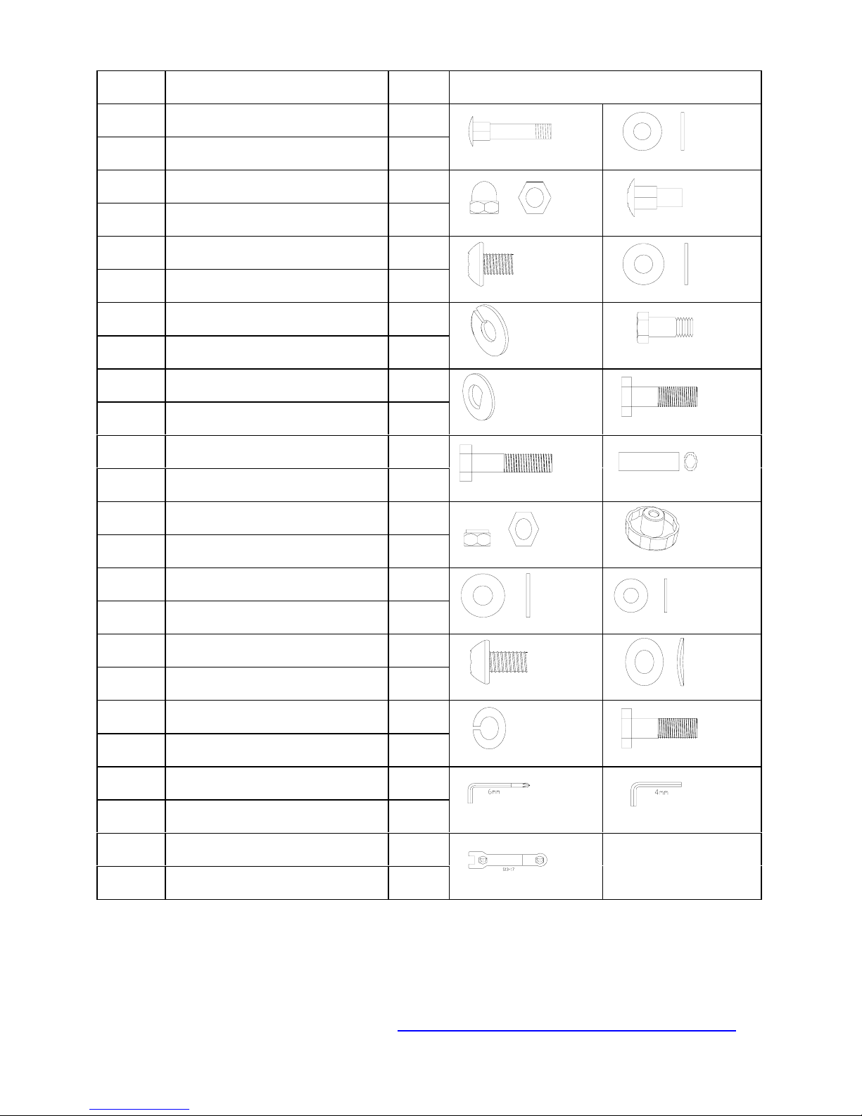
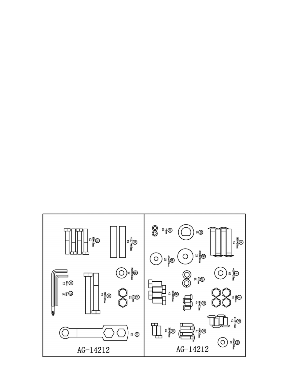
HARDWARE PARTS LIST
NO Description Q’ty Drawings
IF YOU’RE MISSING ANY PARTS PLEASE CALL TECHNICAL SUPPORT
ON 0845 600 0464 OR EMAIL:
fitnessequipment.enquiries@argos.co.uk
2 Carriage bolt M10*55 4
4 Flat washer Ф10*Ф25 6
2
4
5 Domed nut M10 4
21 Carriage bolt Ф8*20 4
5
21
22 Allen bolt M6*12 4
26
22
Flat washer Ф10*Ф32
26 2
27 Spring washer Ф10 2
28
27
28 Hex head screw M10*20 4
29 D type washer 2
31
29
31 Hex head bolt M8*45 4
32 Hex head bolt M10*78 2
33 Sleeve Ф12.7*65 2
33
32
34 Nylon locknut M10 2
34
42
42 Club knob 4
44
Flat washer Ф10*Ф22
2
46 Flat washer Ф8*Ф25 2
46
44
47 Allen screw M8*16 4
54 Curve washer Ф8*Ф20 4
47
54
59 Spring washer Ф8 2
59
60
60 Hex head screw M8*20 2
99 Allen Key L6 1
100
99
100 Allen Key L4 1
101 Wrench S13,17 2
101

PRE-ASSEMBLY CHECK LIST
PART NO. DESCRIPTION Q’TY
1 Main Frame 1
6 Front stabilizer 1
3 Rear Stabilizer 1
48L/R Pedal L/R 2
10 Computer 1
11 Stationary handlebar 1
12/13 Upper handlebars L/R 2
9 Handlebar post 1
41L/R Pedal tube L/R 2
52/53 Lower handlebar L/R 2
39/40 Front & rear bottom handlebar cover 2
37/38 Front pedal tube cover L/R 2
43 Rear pedal tube cover L & R 2
35/36 Front & rear top handlebar cover 2
24/49 Front & rear stationary handlebar cover 2
Hardware pack 1
Manual 1
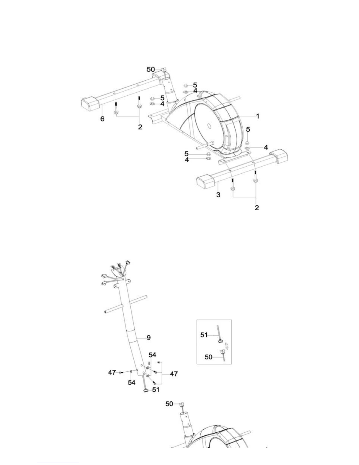
ASSEMBLY
Step 1
Attach the front stabilizer (6) to the front of the main frame (1) secure with two
carriage bolts (2), two flat washers (4), and two domed nuts (5).
Attach the rear stabilizer (3) to the rear of the main frame (1) secure with two
carriage bolts (2), two flat washers (4), and two domed nuts (5).
Step 2
Connect the middle computer wire (51) from the handlebar post (9) to the
lower computer wire (50). (See insert)
Insert the handlebar post (9) into the main frame (1). Secure by using four allen
screws (47) and four curved washers (54).
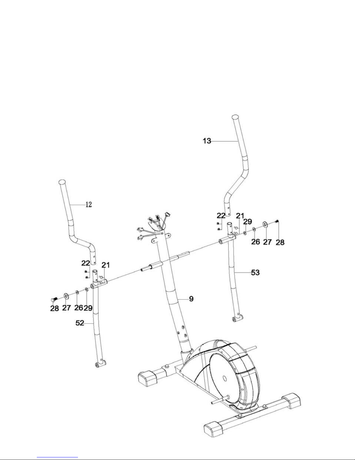
Step 3
Attach the lower left handlebar (52) to the left side axle of the handlebar post (9).
Secure by using D type washer (29), one flat washer (26), one spring washer (27),
one hex head screw (28).
Repeat for the bottom right handlebar (53).
Attach the upper left handlebar (12) to the lower left handlebar (52). Secure by
using two carriage bolts (21) and two allen bolts (22).
Repeat for the upper right handlebar (13).
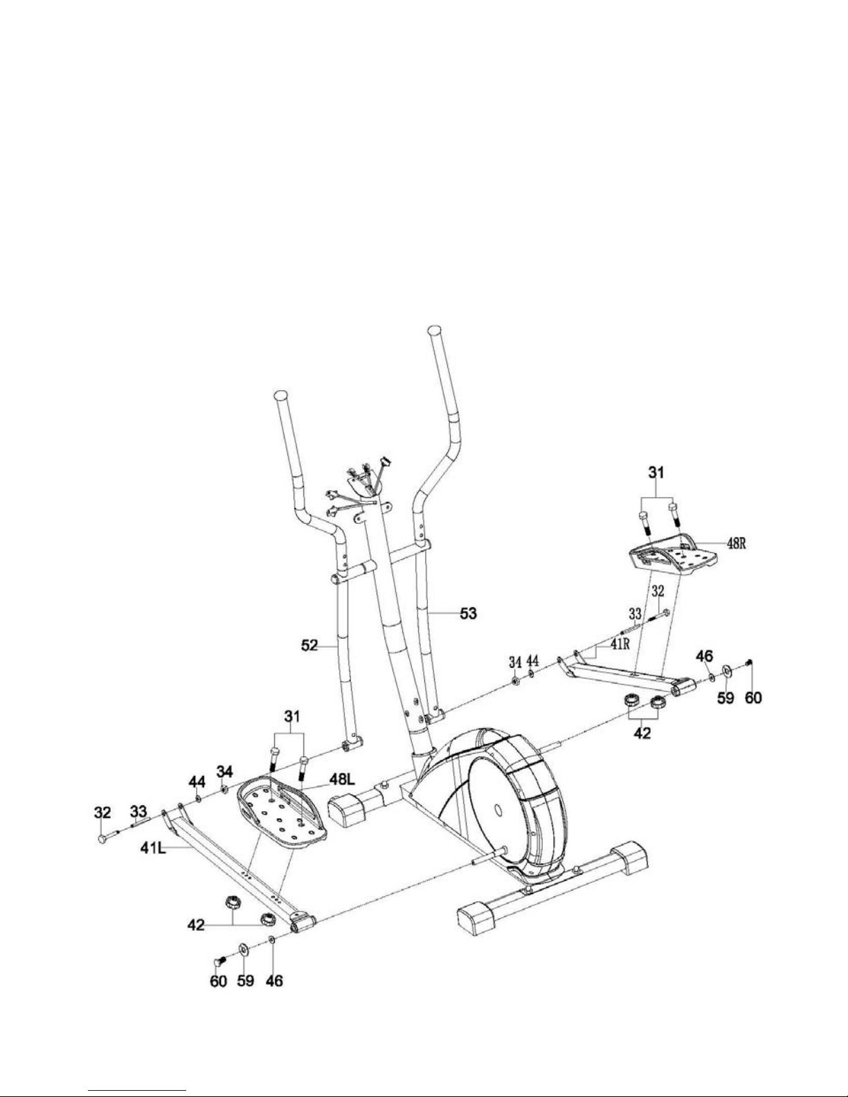
Step 4
Attach the rear of left pedal tube (41R) to the left run disc. Secure by using one hex
head screw (60), one spring washer (59) and one flat washer (46).
Repeat for the right pedal tube (41R).
Attach the left pedal tube (41L) to the lower left handlebar (52). Slide the sleeve (33)
into the left pedal tube and the lower left handlebar. Secure by using one hex head
bolt (32), one flat washer (44), one nylon locknut (34).
Repeat for the right pedal tube (41R).
Attach the Left pedal (48L) to the left pedal tube (41L). Secure in your desired
position using two hex head bolts (31) and two club knobs (42).
Repeat for the Right pedal (48R).
 Loading...