

Rogerblack Gold Magnetic Bike Assembly & User Instructions

1
Assembly
Assembly
Assembly
Assembly &
&
&
& User
User
User
User Instruction
Instruction
Instruction
Instruction –
–
–
– Please
Please
Please
Please keep
keep
keep
keep for
for
for
for future
future
future
future reference
reference
reference
reference
901
901
901
901 /
/
/
/ 7609
7609
7609
7609
Gold
Gold
Gold
Gold Magnetic
Magnetic
Magnetic
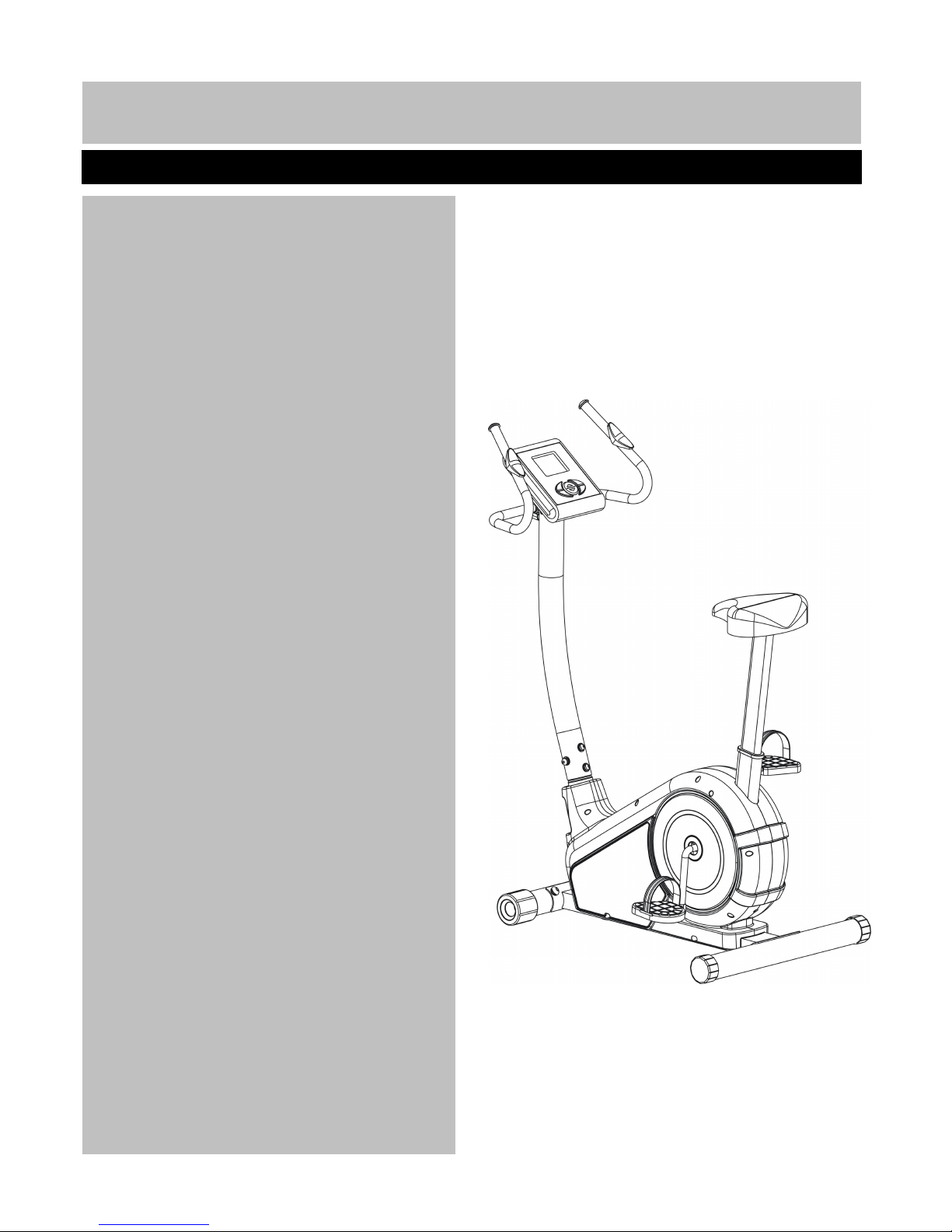
Magnetic Bike
Bike
Bike
Bike
Important
Important
Important
Important –
–
–
– Please
Please
Please
Please read
read
read
read these
these
these
these instructions
instructions
instructions
instructions fully
fully
fully
fully before
before
before
before assembly
assembly
assembly
assembly or
or
or
or using
using
using
using
These Instructions contain important information which will help you get best from your
equipment and ensure safe and correct assembly, use and maintenance.
If you need help or have damaged or missing parts, call the Customer
Customer
Customer
Customer Helpline
Helpline
Helpline
Helpline : 0845
0845
0845
0845 600
600
600
600 0464
0464
0464
0464
2
Contents
Contents
Contents
Contents
Safety
Safety
Safety
Safety Information
Information
Information
Information 3
3
3
3
Components
Components
Components
Components -
-
-
- Parts
Parts
Parts
Parts 4
4
4
4
Components
Components
Components
Components –
–
–
– Fixing
Fixing
Fixing
Fixing 5
5
5
5
Assembly
Assembly
Assembly
Assembly Instruction
Instruction
Instruction
Instruction 6
6
6
6 -
-
-
- 11
11
11
11
Computer
Computer
Computer
Computer Operation
Operation
Operation
Operation 12--
12--
12--
12-- 21
21
21
21
Exercising
Exercising
Exercising
Exercising Information
Information
Information
Information 22
22
22
22
*
*
*
* Before
Before
Before
Before Starting
Starting
Starting
Starting to
to
to
to exercise
exercise
exercise
exercise 22
22
22
22 --
--
--
-- 23
23
23
23
*
*
*
* Muscle
Muscle
Muscle
Muscle Chart
Chart
Chart
Chart 24
24
24
24
*
*
*
* Warming
Warming
Warming
Warming up
up
up
up and
and
and
and Cooling
Cooling
Cooling
Cooling down
down
down
down 25
25
25
25 --
--
--
-- 26
26
26
26
Care
Care
Care
Care and
and
and
and Maintenance
Maintenance
Maintenance
Maintenance 27
27
27
27
Exploded
Exploded
Exploded
Exploded Parts
Parts
Parts
Parts Diagram
Diagram
Diagram
Diagram 28
28
28
28
Exploded
Exploded
Exploded
Exploded Parts
Parts
Parts
Parts List
List
List
List 29--30
29--30
29--30
29--30
Guarantee
Guarantee
Guarantee
Guarantee 3
3
3
3 1
1
1
1

3
T
o reduce the risk of serious injury, read the entire manual before you assemble or operate the Roger Black
Gold Magnetic Bike. In particular, note the following safety precautions:
• Check you have all the components and tools
listed on pages 4 and 5 , bearing in mind that, for
ease of assembly, some components are
pre-assembled.
• Keep children and animals away from the work
area, small parts could choke if swallowed.
• Make sure you have enough space to layout the
parts before starting.
• Assemble the item as close to its final position
(in the same room) as possible.
• Position the equipment on a clear, level surface.
• Dispose of all packaging carefully and responsibly.
Using
Using
Using
Using
• It is the responsibility of the owner to ensure that
all users of this product are properly informed as to
how to use this product safely.
• This product is intended for domestic use only.
Do
Do
Do
Do not
not
not
not use in any commercial, rental, or institutional
setting.
• Before using the equipment to exercise, always do
stretching exercises to properly warm up.
• If the user experiences dizziness, nausea, chest
pain, or other abnormal symptoms stop
stop
stop
stop the
the
the
the
workout
workout
workout
workout and
and
and
and seek
seek
seek
seek immediate
immediate
immediate
immediate medical
medical
medical
medical attention.
attention.
attention.
attention.
• Only one person at a time should use the
equipment.
• Keep hands away from all moving parts.
• Always wear appropriate workout clothing when
exercising. Do
Do
Do
Do not
not
not
not wear loose or baggy clothing,
since it may get caught in the equipment. W ear
athletic shoes to protect your feet while exercising.
• Do
Do
Do
Do not
not
not
not place any sharp objects around the
equipment.
• Disabled persons should not use the equipment
without a qualified person or doctor in attendance.
• This product is suitable for use r’s weight of:
1
1
1
1
25kgs.
25kgs.
25kgs.
25kgs.
• This e quipment is not suitable for therapeutic
purposes .
• Breaking system: 16 level auto programme tension
adjustment. R efer following Computer operation
section.
• This product conforms to: (BS EN957)
-PA R TS 1. 5 class (H) - Home Use - Class (C).
• This exercise product has been designed and
manufactured to comply with the latest (BS EN 957)
British and European Safety Standards.
Warning
Warning
Warning
Warning for
for
for
for the
the
the
the Charger
Charger
Charger
Charger
•
Before using the charger, read the
instruction book carefully.
• This charger is for indoor use only, do not
expose to rain or water.
• If the supplier cord is damaged, it must be
replaced by manufacturer, it ’ s service agent
or similarly qualified persons in order to avoid
a ha zard.
W
W
W
W arning:
arning:
arning:
arning:
Before beginning any exercise program, consult your Doctor. This is especially
important for persons over the age of 35 or persons with pre-existing health problems.You
MUST read all instructions before using any fitness equipment. Argos and its associates assumes no
responsibility for personal injury or property damage sustained by or through the use of this product.
Important
Important
Important
Important –
–
–
– Please
Please
Please
Please read
read
read
read fully
fully
fully
fully before
before
before
before using
using
using
using and
and
and
and assembly
assembly
assembly
assembly
Safety
Safety
Safety
Safety Information
Information
Information
Information
Assembly
Assembly
Assembly
Assembly
4
:
Note:
Note:
Note:
Note:
Some of the smaller components may be pre-fitted to larger components. Please check carefully
before contacting Argos regarding any missing components.
Please
Please
Please
Please check
check
check
check you
you
you
you have
have
have
have all
all
all
all parts
parts
parts
parts list
list
list
list below
below
below
below
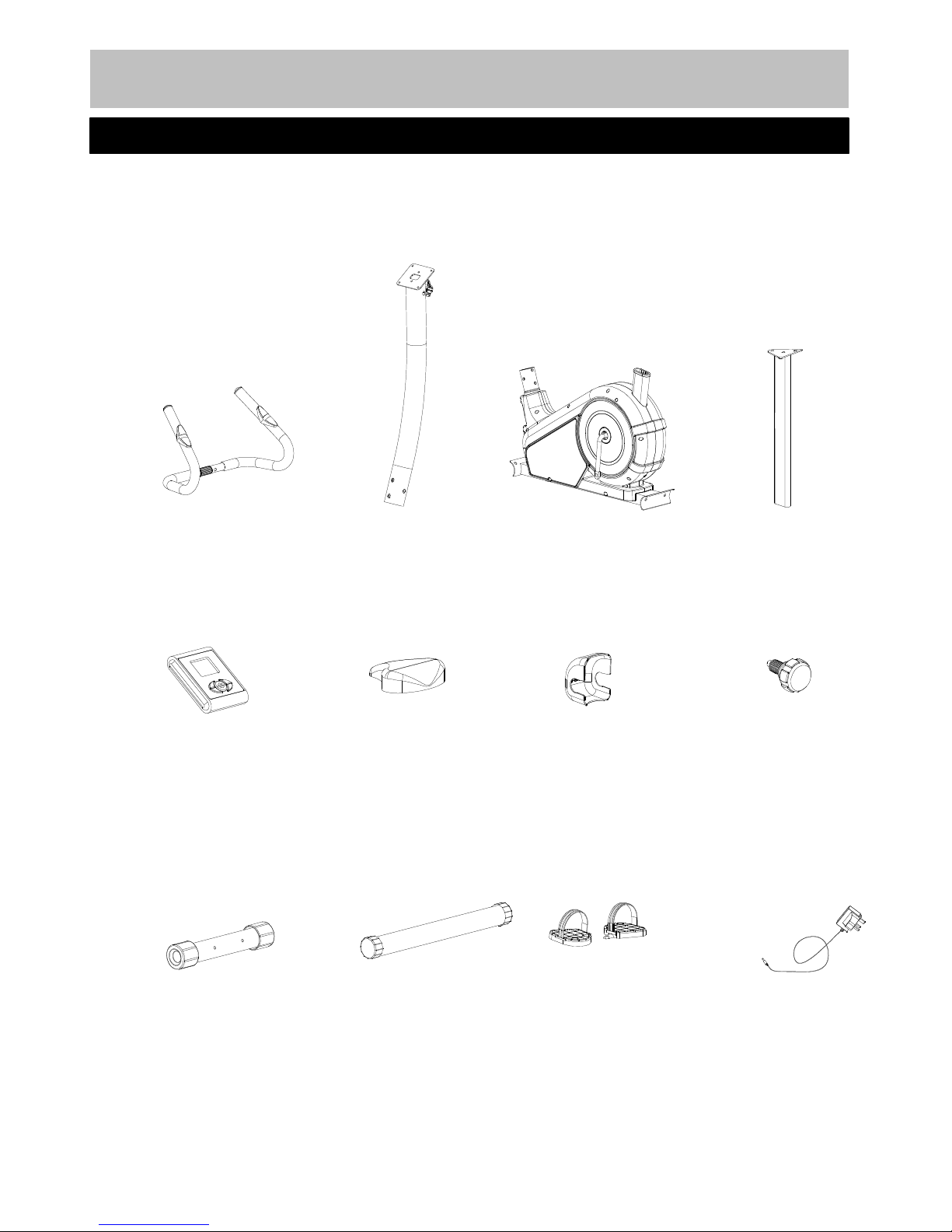
Components-parts
Components-parts
Components-parts
Components-parts
If you have any damaged or missing parts, Please
Call the Customer Helpline: 0845
0845
0845
0845 6000
6000
6000
6000 464
464
464
464
Handl×1
Front Poster×1
Saddle Poster×1
Computer×1
Saddle×1 Handle Cover×1
M16 Lock Knob×1
Front Stabilizer×1
Rear Stabilizer×1
Pedal×1 set
Power Charge×1
Main Frame ×1
5 .
10.
37.
15.
12.
13. 9.
35.
20.
46.
52L&R.
72.
5
:
NOTE
NOTE
NOTE
NOTE
:
:
:
:
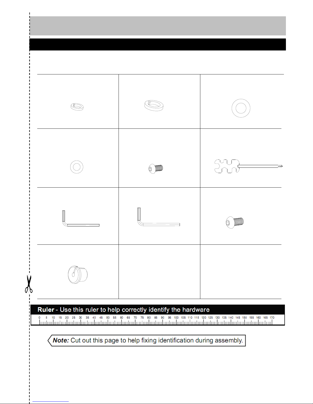
Som e o f th e f ixing s ar e pre- f itte d t o th e large r components . Pleas e chec k carefull y befor e
contactin g Argo s regardin g an y missin g fixings 。
Please
Please
Please
Please check
check
check
check you
you
you
you have
have
have
have all
all
all
all fixings
fixings
fixings
fixings listed
listed
listed
listed below
below
below
below
Components
Components
Components
Components –
–
–
– Fixings
Fixings
Fixings
Fixings
Φ 8MM Spring Washer × 6
7.
7.
7.
7.
22.
22.
22.
22.
Φ 11× Φ 30×R34 Arc Washer×4
21.
21.
21.
21.
Φ 25× Φ 9×R30 Arc Washer× 6
M8*1 6 mm Allen Bolt×6
Multi Wrench ×1
6# Allen Wrench×1
5# Allen Wrench×1
16.
16.
16.
16.
17.
17.
17.
17.
23.
23.
23.
23.
71.
71.
71.
71.
Φ 10MM Spring Washer × 4
M10* 20 mm Allen Bolt× 4
Wire Clip × 2
6
:
NOTE:
NOTE:
NOTE:
NOTE:
Tool
required assembly the machine : two adjustable wrenches, and one P hilips screw driver
Recommend
Recommend
Recommend
Recommend the
the
the
the assembly
assembly
assembly
assembly if
if
if
if this
this
this
this equipment
equipment
equipment
equipment is
is
is
is carried
carried
carried
carried by
by
by
by two
two
two
two person
person
person
person
A
A
A
A ss
ss
ss
ss embly
embly
embly
embly Instruction
Instruction
Instruction
Instruction
a.
a.
a.
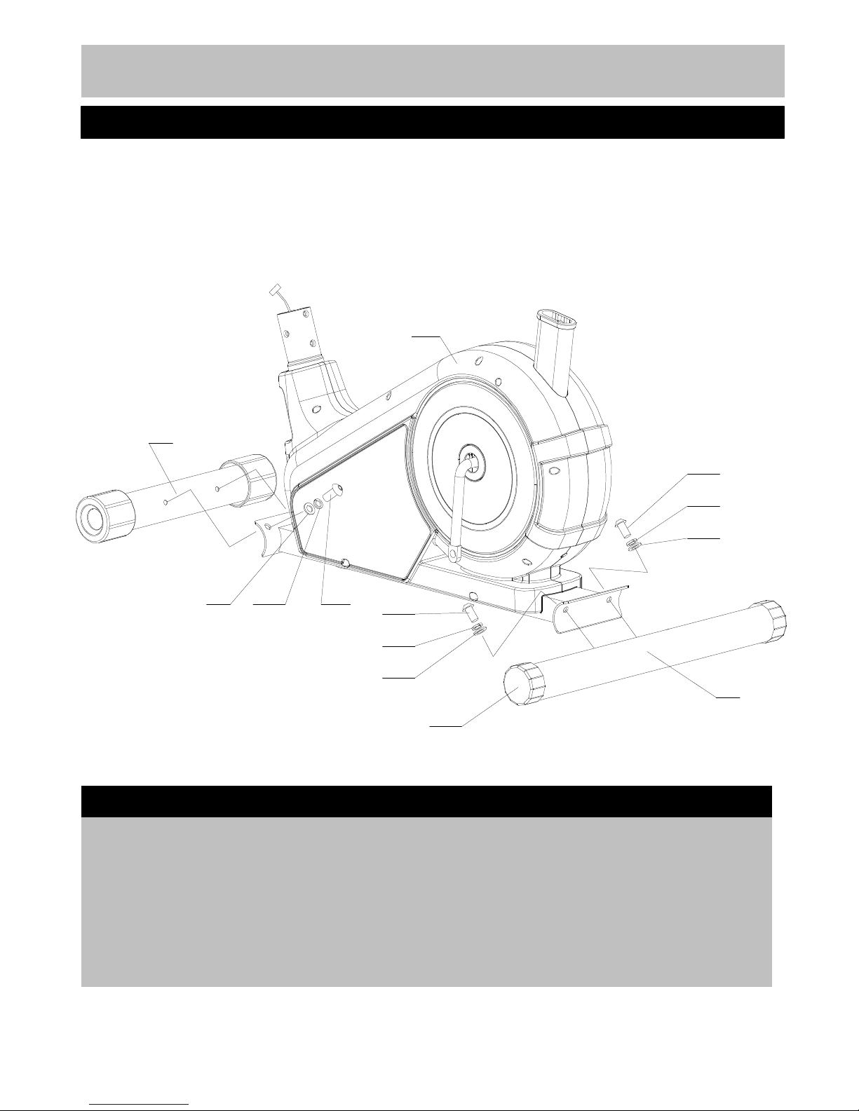
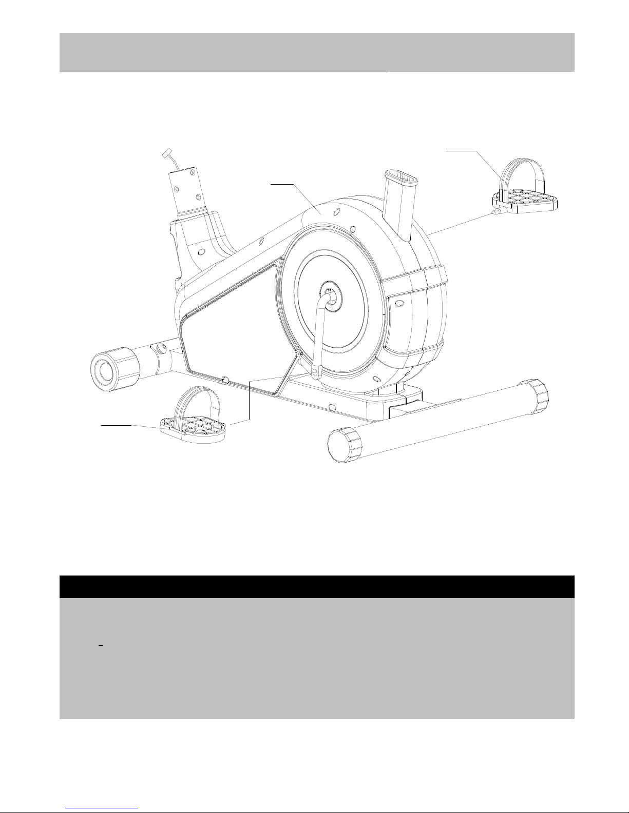
a. Attach Front stabilizer (20)
(20)
(20)
(20) to Main body (1)
(1)
(1)
(1) c.
c.
c.
c. Leverage
Leverage
Leverage
Leverage the
the
the
the machine
machine
machine
machine
using two M10 x20mm Allen bolts (23),
(23),
(23),
(23), Ø 10mm Slightly turn round the two Level feet (47)
(47)
(47)
(47) to
Spring washer s ( 22)
22)
22)
22) ,
,
,
, Ø
11
x Ø 30 x R34mm Arc adjust the level of the machine.
washers (21).
(21).
(21).
(21).
b.
b.
b.
b. Repeat step a
a
a
a to install Rear stabilizer (46)
(46)
(46)
(46)
to Main body (1).
(1).
(1).
(1).
Step
Step
Step
Step 1
1
1
1
a
a
a
a
b
b
b
b
20
21 22 23
46
23
22
21
23
22
21
47
1
7
A
A
A
A ss
ss
ss
ss embly
embly
embly
embly Instruction
Instruction
Instruction
Instruction
Step
Step
Step
Step 2
2
2
2
a.
a.
a.
a. Connect Foot pedal (
(
(
( 52
52
52
52 R
R
R
R &
&
&
& 52L
52L
52L
52L )
)
)
) to crank on the Main body (1)
(1)
(1)
(1) as shown.
NOTE
NOTE
NOTE
NOTE :
:
:
:
For the two foot pedals, the left one is remarked "L" and right one remarked "R". Fasten the left
foot pedal by anti-clockwise direction and turn the right pedal by clockwise dire c tion.
a
a
a
a
52L
52R
1
8
:
A
A
A
A ss
ss
ss
ss embly
embly
embly
embly Instruction
Instruction
Instruction
Instruction
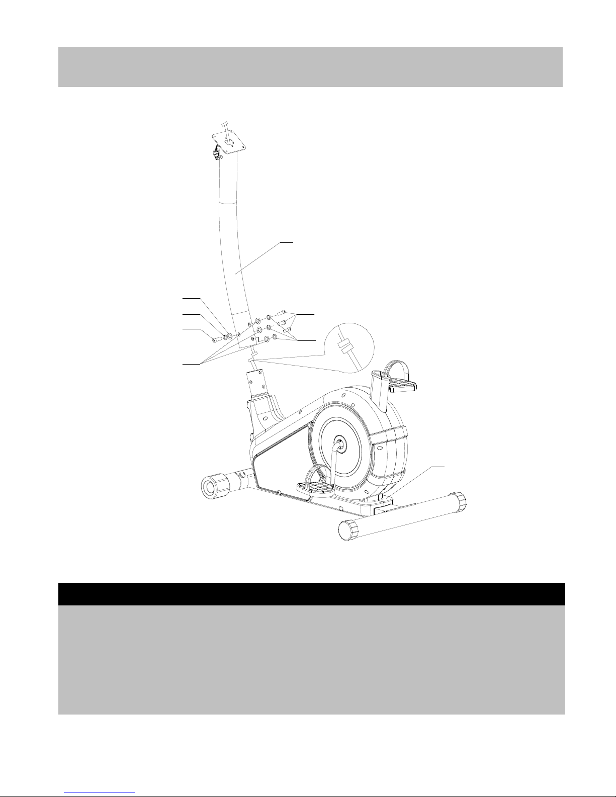
a.
a.
a.
a. Connect Main wire ( A
A
A
A ) from Main body (1)
(1)
(1)
(1) b.
b.
b.
b. Attach Front poster (10)
(10)
(10)
(10) to Main body (1)
(1)
(1)
(1)
to Main wire (A
(A
(A
(A ’
’
’
’ ) in the Front poster (1)
(1)
(1)
(1) as shown using six M8 x 16mm Allen bolts (17),
(17),
(17),
(17), Ø 8mm
in the diagram. w asher s (7),
(7),
(7),
(7), and Ø 25x9xR30mm Arc washer s
(16).
(16).
(16).
(16).
Step
Step
Step
Step 3
3
3
3
16
7
17
7
17
16
10
A
A'
1
9
:
A
A
A
A ss
ss
ss
ss embly
embly
embly
embly Instruction
Instruction
Instruction
Instruction
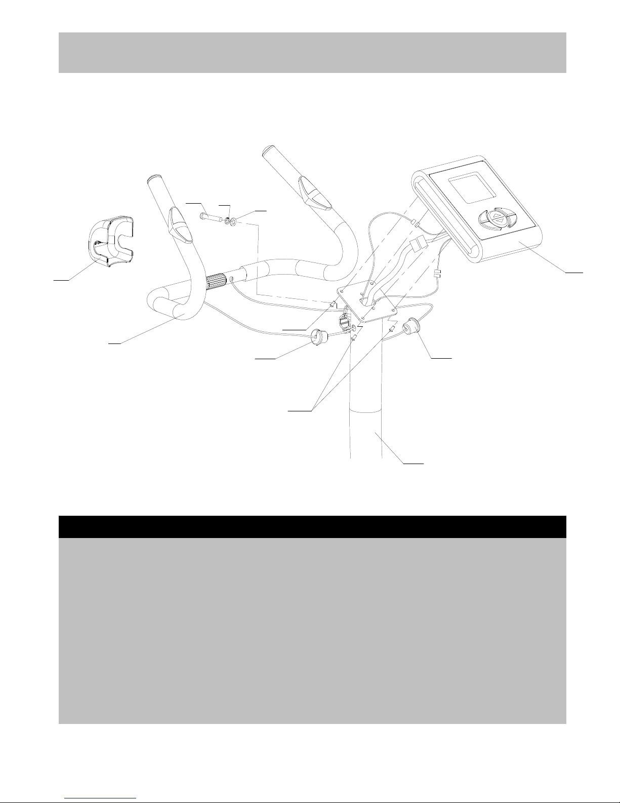
a.
a.
a.
a. Insert two Wire holder (71)
(71)
(71)
(71) to the holes on c.
c.
c.
c. Connect Main wire (A
(A
(A
(A ’
’
’
’ )
)
)
) in the Front Poster
The side of the Front poster (10),
(10),
(10),
(10), Feed the (10)
(10)
(10)
(10) to the wire from the Computer (12).
(12).
(12).
(12).
Pulse sensor wire (
(
(
( C
C
C
C &
&
&
& D
D
D
D )
)
)
) through the Wire
clip s (71)
(71)
(71)
(71) and connect to the Pulse sensor s d
d
d
d . Loosing four M5 x 15mm Flat head philips
wire s from the Computer (12).
(12).
(12).
(12). S crews (11)
(11)
(11)
(11) from the bottom of Computer
(12).
b
b
b
b . Attach the handle to the bracket on the Attach the Computer (12) onto the top of the
Front poster (10)
(10)
(10)
(10) using M8 x 40mm Allen bolt Front poster (10), fix using these four M5 x15
( 6),
6),
6),
6), Ø 8mm Washer (7)
(7)
(7)
(7) and Ø 8mm Big Washe r
r
r
r mm Flat head philips screws ( 11).
11).
11).
11).
(8).
(8).
(8).
(8).
Attach the Handle cover (9) onto the bracket. .
Step
Step
Step
Step 4
4
4
4
9
5
11
12
71
71
11
A'
C
D
10
6
7
8
10
Assembly
Assembly
Assembly
Assembly Instruction
Instruction
Instruction
Instruction
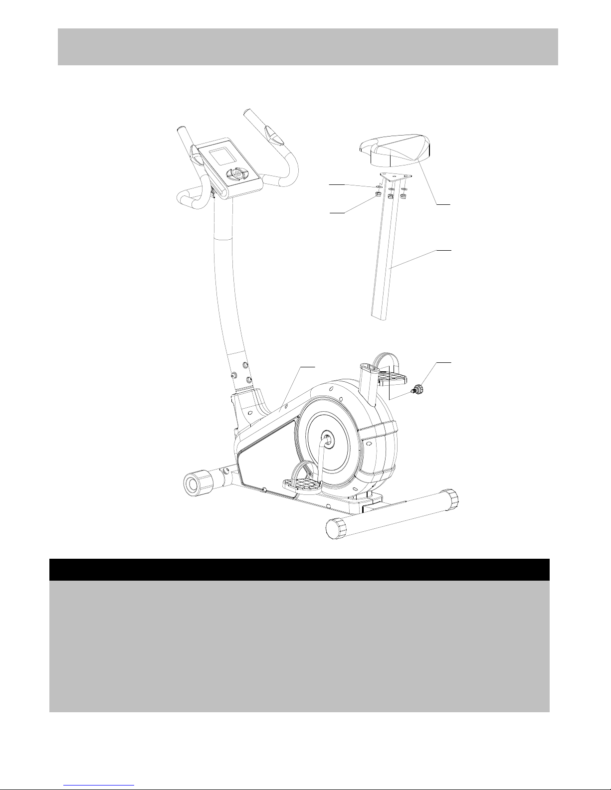
Step
Step
Step
Step 5
5
5
5
a.
a.
a.
a. Loosing the three M8 Aircraft nuts (14)
(14)
(14)
(14) and c.
c.
c.
c. Insert the Saddle poster (15)
(15)
(15)
(15) into the Main
Ø 8mm Washers (8)
(8)
(8)
(8) from the bottom of the body (1),
(1),
(1),
(1), get your desired height and secure
Saddle ( 13)
13)
13)
13) . With M16 Lock knob (35).
b.
b.
b.
b. Attach the Saddle (13)
(13)
(13)
(13) on the Saddle poster
(15)
(15)
(15)
(15) using three M8 Aircraft nuts (14)
(14)
(14)
(14) and Ø 8mm
Washers (8)
(8)
(8)
(8) .
35
13
14
8
15
1
 Loading...