

Rockwell Automation 1756 ControlLogix, 1756 GuardLogix, 1769 CompactLogix, 1769 Compact GuardLogix, 1789 SoftLogix User Manual
...Page 1

User Manual
DeviceNet Network Configuration
1756 ControlLogix, 1756 GuardLogix, 1769 CompactLogix,
1769 Compact GuardLogix, 1789 SoftLogix, Studio 5000
Logix Emulate
Publication DNET-UM004D-EN-P
Original Instructions
Page 2
DeviceNet Network Configuration
personal injury or death, property damage, or economic loss.
Attentions help you identify a hazard, avoid a hazard, and recognize the consequence.
IMPORTANT
Identifies information that is critical for successful application and understanding of the product.
temperatures.
for Personal Protective Equipment (PPE).
Important User Information
Read this document and the documents listed in the additional resources section about installation, configuration, and
operation of this equipment before you install, configure, operate, or maintain this product. Users are required to familiarize
themselves with installation and wiring instructions in addition to requirements of all applicable codes, laws, and standards.
Activities including installation, adjustments, putting into service, use, assembly, disassembly, and maintenance are required to
be carried out by suitably trained personnel in accordance with applicable code of practice.
If this equipment is used in a manner not specified by the manufacturer, the protection provided by the equipment may be
impaired.
In no event will Rockwell Automation, Inc. be responsible or liable for indirect or consequential damages resulting from the use
or application of this equipment.
The examples and diagrams in this manual are included solely for illustrative purposes. Because of the many variables and
requirements associated with any particular installation, Rockwell Automation, Inc. cannot assume responsibility or liability for
actual use based on the examples and diagrams.
No patent liability is assumed by Rockwell Automation, Inc. with respect to use of information, circuits, equipment, or software
described in this manual.
Reproduction of the contents of this manual, in whole or in part, without written permission of Rockwell Automation, Inc., is
prohibited.
Throughout this manual, when necessary, we use notes to make you aware of safety considerations.
WARNING: Identifies information about practices or circumstances that can cause an explosion in a hazardous environment, which may lead to
ATTENTION: Identifies information about practices or circumstances that can lead to personal injury or death, property damage, or economic loss.
Labels may also be on or inside the equipment to provide specific precautions.
SHOCK HAZARD: Labels may be on or inside the equipment, for example, a drive or motor, to alert people that dangerous voltage may be present.
BURN HAZARD: Labels may be on or inside the equipment, for example, a drive or motor, to alert people that surfaces may reach dangerous
ARC FLASH HAZARD: Labels may be on or inside the equipment, for example, a motor control center, to alert people to potential Arc Flash. Arc Flash
will cause severe injury or death. Wear proper Personal Protective Equipment (PPE). Follow ALL Regulatory requirements for safe work practices and
2 Rockwell Automation Publication DNET-UM004D-EN-P - September 2020
Page 3

Subject
Reason
Summary of Changes
This manual includes new and updated information. Use these reference
tables to locate changed information.
Grammatical and editorial style changes are not included in this summary.
Global changes
This table identifies changes that apply to all information about a subject in
the manual and the reason for the change. For example, the addition of new
supported hardware, a software design change, or additional reference
material would result in changes to all of the topics that deal with that subject.
Updated the Legal notices. Legal information changed.
New or enhanced features
None in this release.
Rockwell Automation Publication DNET-UM004D-EN-P - September 2020 3
Page 4

Page 5

Summary of Changes
DeviceNet Overview
Connect a Computer to the
Connect Devices to the Network
Configure the Network Offline
Table of Contents
Preface
Network Configuration ............................................................................. 11
Studio 5000 environment ......................................................................... 12
Additional Resources ................................................................................. 12
Legal Notices ............................................................................................... 13
Chapter 1
Choose a Single Network or Subnets ....................................................... 15
Single Network ..................................................................................... 15
Advantages to Using a Single Network ........................................ 15
Disadvantages to Using a Single Network ................................... 16
Subnets ................................................................................................. 16
Advantages to Using Subnets ....................................................... 16
Disadvantages to Using Subnets .................................................. 16
Choose a Scanner ....................................................................................... 16
Bridge Across Networks ............................................................................. 17
Choose a Baud Rate for the Network ........................................................ 19
Assign an Address to Each Device ............................................................ 20
Required Software ...................................................................................... 21
DeviceNet Network
Chapter 2
Connection Options ..................................................................................23
Set Up the DeviceNet Driver .................................................................... 24
Obtain the Driver for the Interface Device ....................................... 24
Verify that the Driver Works .............................................................. 24
Chapter 3
Before You Begin....................................................................................... 27
Set the Node Address of a Device ............................................................ 27
Set Node Address via Hardware Mechanism ................................... 28
Set Node Address via Software .......................................................... 29
Set Node Address via DeviceNet Node Commissioning Tool ......... 30
Make Sure Your Devices Are on Your Network ........................................32
Chapter 4
Before You Begin........................................................................................ 33
Create a File for the Network .................................................................... 33
Create Your Network in RSNetWorx for DeviceNet Software ............... 34
Configure Each Device ............................................................................... 35
Specify a Device Node Address ........................................................... 36
Change a Device Node Address .................................................... 37
Rockwell Automation Publication DNET-UM004D-EN-P - September 2020 5
Page 6

Table of Contents
Configure the Network Online
Automatically Configure a
DeviceNet Network
Configure Device Parameters ............................................................ 38
Configure the Scanner ............................................................................... 39
Build the Scan List............................................................................... 40
Set the Alignment Option ................................................................... 42
SoftLogix 5800 Controller ............................................................. 43
Manually Assign Each Device to a Memory Location ........................ 43
Save the Configuration File ....................................................................... 45
Generate an RSNetWorx for DeviceNet Report ...................................... 45
Go Online to Your Network ....................................................................... 47
Download Configuration to Your Network ............................................. 49
Chapter 5
Before You Begin........................................................................................ 51
Verify Communication Between the Computer and Devices ............... 52
Create a New File for the Network ............................................................ 53
Go Online to Your Network ....................................................................... 54
Configure Each Device ............................................................................... 56
Upload the Configuration of a Device ................................................ 56
Change and Download Device Configuration ................................... 56
Configure the Scanner ............................................................................... 57
Upload the Current Scanner Configuration ..................................... 58
Define the Scanner Properties ............................................................ 59
Build the Scan List............................................................................... 60
Set the Alignment Option ................................................................... 62
SoftLogix 5800 Controller ............................................................. 63
Manually Assign Each Device to a Memory Location ........................ 63
Download the Configuration to the Scanner ..................................... 65
Upload and Save the Configuration File................................................... 65
Generate an RSNetWorx for DeviceNet Report ..................................... 66
6 Rockwell Automation Publication DNET-UM004D-EN-P - September 2020
Chapter 6
How AutoScan Operates .......................................................................... 69
Determine If You Can Use AutoScan ....................................................... 71
How AutoScan Affects Your Network ..................................................... 72
Install the DeviceNet Node Commissioning Tool ................................... 73
Connect Devices ......................................................................................... 73
Install a Scanner or Network Interface Devices ................................ 73
Install Other DeviceNet Devices ......................................................... 74
Set the Node Address and Baud Rate with the DeviceNet Node
Commissioning Tool ............................................................................ 75
Add the Scanner to the RSLogix 5000 Project .......................................... 75
Add the Scanner to the I/O Configuration Folder ............................. 75
Page 7

Control a Device
Interlock and Share Inputs
Table of Contents
Define the Properties of the Scanner ................................................. 76
Enable AutoScan with RSLogix 5000 Software ....................................... 77
Initiate AutoScan via the User Program .................................................. 78
Implementing AutoScan .................................................................... 78
Configure I/O Allocation Size Via the User Program ................ 80
Configure I/O Allocation Via a DeviceView Configurator......... 80
Initiate AutoScan via the User Program ...................................... 81
Initiate AutoScan via the DeviceView Configurator ................... 81
Additional Considerations Regarding AutoScan ............................. 82
Access Device Data .................................................................................... 83
Put the Scanner in Run Mode .................................................................. 84
Additional Information About AutoScan ................................................ 85
Type of Connection that the Scanner Sets Up .................................. 85
Allocating More Memory for Each Device ........................................ 85
Chapter 7
Before You Begin....................................................................................... 87
RSNetWorx Report for the Network ................................................. 88
Data Map for Each of Your Devices ................................................... 89
Add the Scanner to the Controller’s I/O Configuration ......................... 89
Conserve EtherNet/IP or ControlNet Network Bandwidth ............ 89
Add the Scanner to the I/O Configuration Folder ............................ 90
Configure the Scanner ......................................................................... 91
Determine the Address of DeviceNet Data ............................................. 92
SoftLogix 5800 Controller .................................................................. 94
Determine If a Device Has Failed ............................................................. 95
Place the Scanner in Run Mode................................................................ 96
When to Use an MSG Instruction ............................................................ 96
Determine the Parameter Number to Access .......................................... 97
Determine the Configuration of the Parameter ...................................... 97
Test the Parameter .................................................................................... 98
Enter Message Logic ................................................................................. 99
Define the Source or Destination Data ............................................ 101
Enter and Configure the MSG Instruction ...................................... 102
Set the Communication Path ............................................................ 103
Rockwell Automation Publication DNET-UM004D-EN-P - September 2020 7
Chapter 8
Interlock ................................................................................................... 105
Choose a Master Controller ............................................................... 106
Determine How Much Data to Exchange ........................................ 106
Enable Slave Mode for the Slave Scanner ........................................ 106
Map the Slave Mode Data .................................................................. 107
Page 8

Table of Contents
Communicate with a PanelView
Standard Terminal
Add the Slave to the Master Scanner’s Scan List .............................108
Map the Data of the Slave .................................................................. 109
Place Both Scanners In Run Mode .................................................... 109
Share Inputs ............................................................................................. 109
Add the Input to the First Scanner ................................................... 109
Add the Input to the Second Scanner ............................................... 109
Map the Input Data in the Second Scanner ..................................... 110
Chapter 9
Choose Data Types .................................................................................... 111
Choose a Communication Method ......................................................... 112
I/O Slave Communication ................................................................. 112
Explicit Server Communication ........................................................ 113
Explicit Client Communication ......................................................... 113
Plan and Configure I/O Slave Tags .......................................................... 113
Use a Word/Bit Format for Each Tag ............................................... 114
For Integers, Skip Every Other Word ............................................... 115
Configure an I/O Slave Tag ............................................................... 115
Set Up the Terminal on Your Network ................................................... 116
Set the Protocol .................................................................................. 116
Set the Node Address and I/O Sizes ..................................................117
Configure the Scanner to Update I/O Slave Tags .................................. 118
Add the Terminal to the Scan List ..................................................... 118
Edit I/O Parameters ........................................................................... 119
Map Input and Output Data ............................................................. 120
Address I/O Slave Tags in the RSLogix 5000 Programming Software
Project ....................................................................................................... 120
SoftLogix 5800 Controller ................................................................. 122
Plan and Configure Explicit Server Tags ................................................ 122
Assign Assembly Instances ................................................................ 123
For Integers, Skip Every Other Word ............................................... 124
Configure an Explicit Server Tag ...................................................... 124
Program the Controller to Get/Set Explicit Server Tags ....................... 125
Create an Array for the Assembly Instance ...................................... 125
Enter and Configure the MSG Instruction ...................................... 126
Set the Communication Path ............................................................ 127
Configure Explicit Client Tags ................................................................ 128
Determine the Parameter Number to Access .................................. 128
Determine the Configuration of the Parameter .............................. 129
Configure an Explicit Client Tag ...................................................... 129
8 Rockwell Automation Publication DNET-UM004D-EN-P - September 2020
Page 9

Communicate with a
FactoryTalk View Project
Tune the Performance of a
DeviceNet Network
Failed Device
Map the Memory Location with
Advanced Mapping
Table of Contents
Chapter 10
Before You Begin...................................................................................... 132
Create a Topic for the Device .................................................................. 132
Create a Node ........................................................................................... 133
Create a Tag for the Parameter ............................................................... 134
Chapter 11
Factors that Affect Performance ............................................................. 137
I/O Parameters of Each Device ......................................................... 139
Background Poll ................................................................................. 139
Interscan Delay .................................................................................. 140
Change the Configuration of Your Network .......................................... 141
Upload the Current Configuration of the Scanner ......................... 141
Set the Interscan Delay and Poll Ratio ............................................. 142
Set the I/O Parameters of a Device ................................................... 143
Change of State or Cyclic Transfer ............................................. 143
Strobed Transfer .......................................................................... 144
Polled Transfer ............................................................................. 144
Download the Configuration to the Scanner ................................... 145
Save the Configuration File ............................................................... 145
Automate the Replacement of a
Chapter 12
Automatic Device Recovery ..................................................................... 147
Set Up Automatic Device Recovery ........................................................ 148
Choose an Electronic Key Level for a Device .................................... 148
Update Your Network Configuration File ........................................ 149
Define the Electronic Key .................................................................. 149
Enable Auto-Address Recovery for the Scanner .............................. 150
Set the ADR Settings for the Device ................................................. 151
Download the Changes to the Scanner ............................................ 151
Upload and Save the Configuration File .......................................... 152
Appendix A
Give a Value Its Own Memory Location ................................................. 153
Rockwell Automation Publication DNET-UM004D-EN-P - September 2020 9
Page 10

Page 11

Task
Optional Conditions
Required Conditions
network offline
network offline
Network Configuration
Preface
This manual describes how you can use DeviceNet modules with your
Logix5000 controller and communicate with various devices on the DeviceNet
network.
You should use this manual if you program applications that use DeviceNet
with one of these Logix5000 controllers:
• 1756 ControlLogix controllers
• 1768 CompactLogix controllers
• 1769 CompactLogix controllers
• 1789 SoftLogix 5800 controllers
• PowerFlex 700S with DriveLogix controllers
You should also understand the following:
• Networking concepts
• RSNetWorx for DeviceNet software
• RSLogix 5000 programming software
• RSLinx Classic communication software
The following chapters describe how to set up a DeviceNet network:
• Chapter 2—Connect a Computer to the DeviceNet Network on page 23
• Chapter 3—Connect Devices to the Network on page 73
• Chapter 4—Configure the Network Offline on page 33
• Chapter 5—Configure the Network Online on page 33
You are not required to complete all tasks in each chapter in the exact order
presented to set up your DeviceNet application. For example, you can
configure your network offline before you connect a computer to the network.
However, there are some requirements related to the order in which you
complete tasks. For example, you must complete the tasks in chapters 2 and 3
before you can configure the network online.
The following table describes optional and required conditions to consider
when determining the order in which you plan to complete tasks in your
DeviceNet application.
Network Configuration Tasks
Connect a computer to the network • Can be completed before or after connecting
devices to the network
Can be completed before or after configuring the
•
Must be completed before configuring the network
online
Connect devices to the network • Can be completed before or after connecting a
Rockwell Automation Publication DNET-UM004D-EN-P - September 2020 11
computer to the network
Can be completed before or after configuring the
•
Must be completed before configuring the network
online
Page 12
Preface
Task
Optional Conditions
Required Conditions
online
Resource
Description
publication DNET-IN001
ADN, and 1769-SDN DeviceNet modules.
publication DNET-UM072
DeviceNet cable system.
Studio 5000 environment
Additional Resources
Configure the network offline • Can be completed before or after connecting a
computer to the network
• Can be completed before or after connecting
devices to the network
Can be completed before configuring the network
•
Configure the network online Can be completed without creating a network
configuration file offline
The Studio 5000 Automation Engineering & Design Environment® combines
engineering and design elements into a common environment. The first
element is the Studio 5000 Logix Designer® application. The Logix Designer
application is the rebranding of RSLogix 5000® software and will continue to
be the product to program Logix 5000™ controllers for discrete, process,
batch, motion, safety, and drive-based solutions.
None
• Computer must be connected to the network
before configuring the network online
• Devices must be connected to the network before
configuring the network online
12 Rockwell Automation Publication DNET-UM004D-EN-P - September 2020
The Studio 5000® environment is the foundation for the future of
Rockwell Automation® engineering design tools and capabilities. The Studio
5000 environment is the one place for design engineers to develop all
elements of their control system.
For more information on the products included in this publication, use the
publications listed in this table.
DeviceNet Modules Installation Instructions,
DeviceNet Media Design Installation Guide,
Logix5000 Controllers Common Procedures
Programming Manual, publication 1756-PM001M
Describes how to install and set up 1756-DNB, 1769-
Describes how to design, install, and troubleshoot a
Links to a collection of programming manuals that
describe how you can use procedures that are
common to all Logix5000 controller projects.
Page 13

Legal Notices
Preface
Rockwell Automation publishes legal notices, such as privacy policies, license
agreements, trademark disclosures, and other terms and conditions on the
Legal Notices
page of the Rockwell Automation website.
End User License Agreement (EULA)
You can view the Rockwell Automation End-User License Agreement ("EULA")
by opening the License.rtf file located in your product's install folder on your
hard drive.
Open Source Licenses
The software included in this product contains copyrighted software that is
licensed under one or more open source licenses. Copies of those licenses are
included with the software. Corresponding Source code for open source
packages included in this product are located at their respective web site(s).
Alternately, obtain complete Corresponding Source code by contacting
Rockwell Automation via the Contact form on the Rockwell Automation
website:
http://www.rockwellautomation.com/global/aboutus/contact/contact.page
Please include "Open Source" as part of the request text.
A full list of all open source software used in this product and their
corresponding licenses can be found in the OPENSOURCE folder. The default
installed location of these licenses is
Files\Rockwell\Help\FactoryTalk Services Platform\Release
Notes\OPENSOURCE\index.htm
C:\Program Files (x86)\Common
.
Rockwell Automation Publication DNET-UM004D-EN-P - September 2020 13
Page 14

Page 15
Topic
Page
Choose a Scanner on page 16
16 on page 16
Bridge Across Networks on page 17
16 on page 17
Choose a Baud Rate for the Network on page 19
19 on page 19
Calculate Scanner Memory Requirements
20
Assign an Address to Each Device on page 20
23 on page 20
Choose a Single Network or
Single Network
Advantages to Using a
Chapter 1
DeviceNet Overview
The Logix5000 family of controllers operates with many DeviceNet
communication modules. This chapter describes each communication module
and the preliminary tasks you must complete before your configure and
program the DeviceNet network.
Choose a Single Network or Subnets 14 on page 15
Subnets
Single Network
DeviceNet communication modules share these features:
• Interface via cabling systems using either round or flat media that
provide both power and communication
• Use network protocols
• Require no network scheduling
• Support messaging, produced/consumed data, and distributed I/O
You can organize the devices on the network in a single network or several,
smaller distributed networks known as subnets.
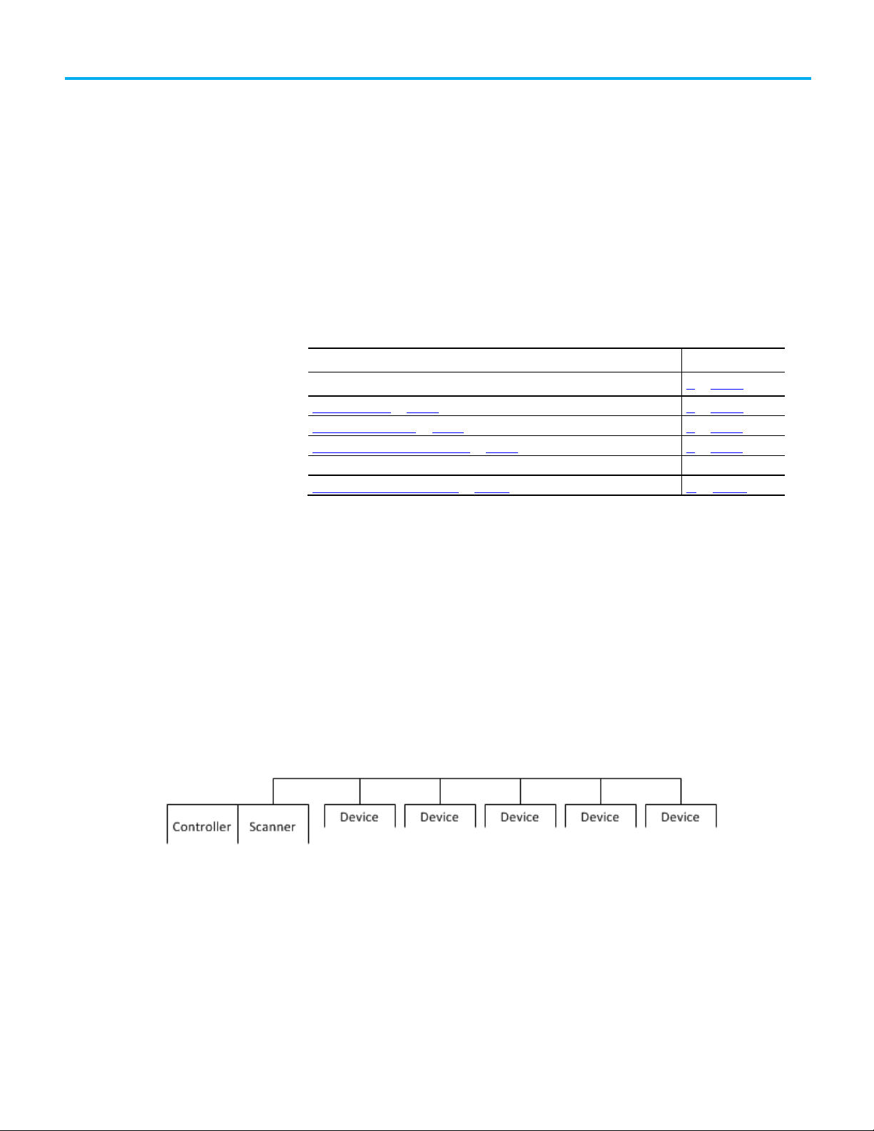
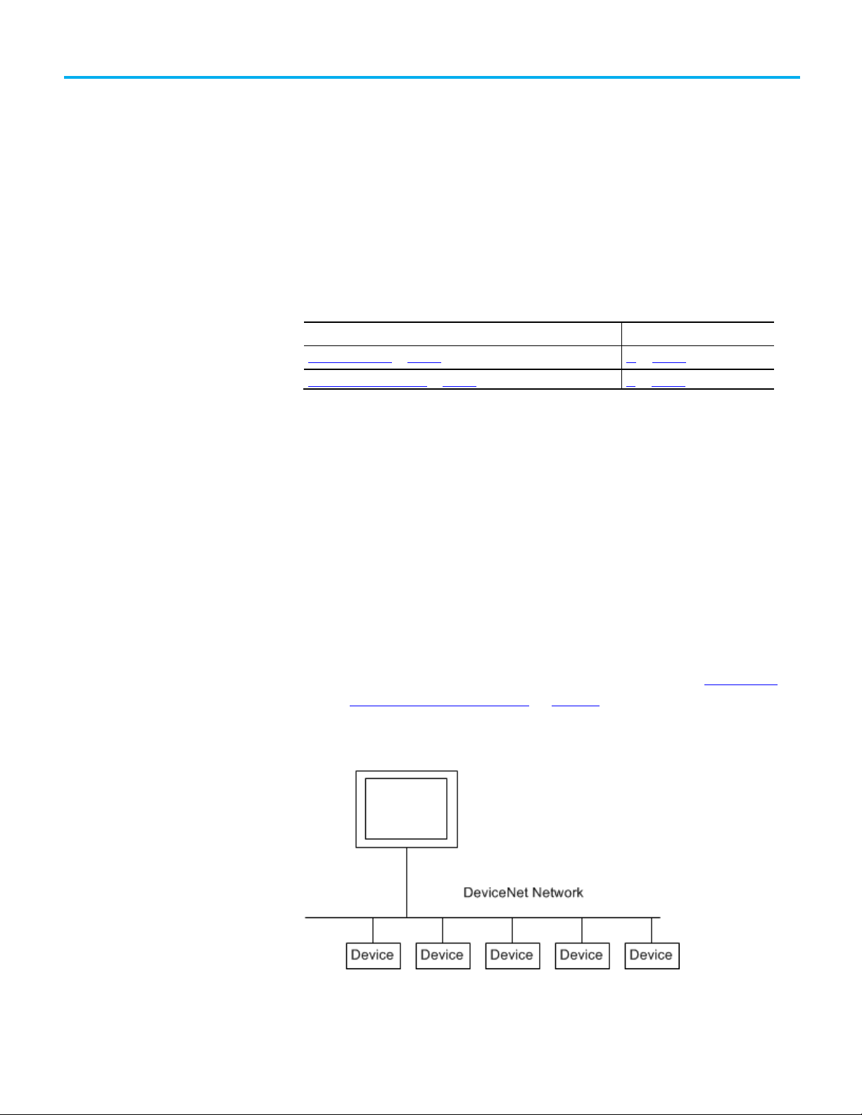
When you use a single network, you place all your devices on a single
DeviceNet network and connect the controller directly to the network via a
scanner. The following graphic shows a single network.
There are advantages to using a single network for your DeviceNet
application:
• The overall cost to install the network is lower than using subnets.
• You need to manage only a single network.
• The Logix5000 controller is local to the DeviceNet scanner. For
example, with a single network in a ControlLogix application, the 1756L64 controller is in the same ControlLogix chassis as the 1756-DNB
scanner.
Rockwell Automation Publication DNET-UM004D-EN-P - September 2020 15
Page 16
Chapter 1 DeviceNet Overview
Disadvantages to Using a
Subnets
Advantages to Using
Disadvantages to Using
Choose a Scanner
Single Network
There are disadvantages to using a single network for your DeviceNet
application:
• The network must use shorter distances from one end to another.
• The more devices on the network, the slower the overall performance
of the network.
• Your network may have more power supply requirements than can be
handled by one network
• A single network can contain only up to 64 nodes
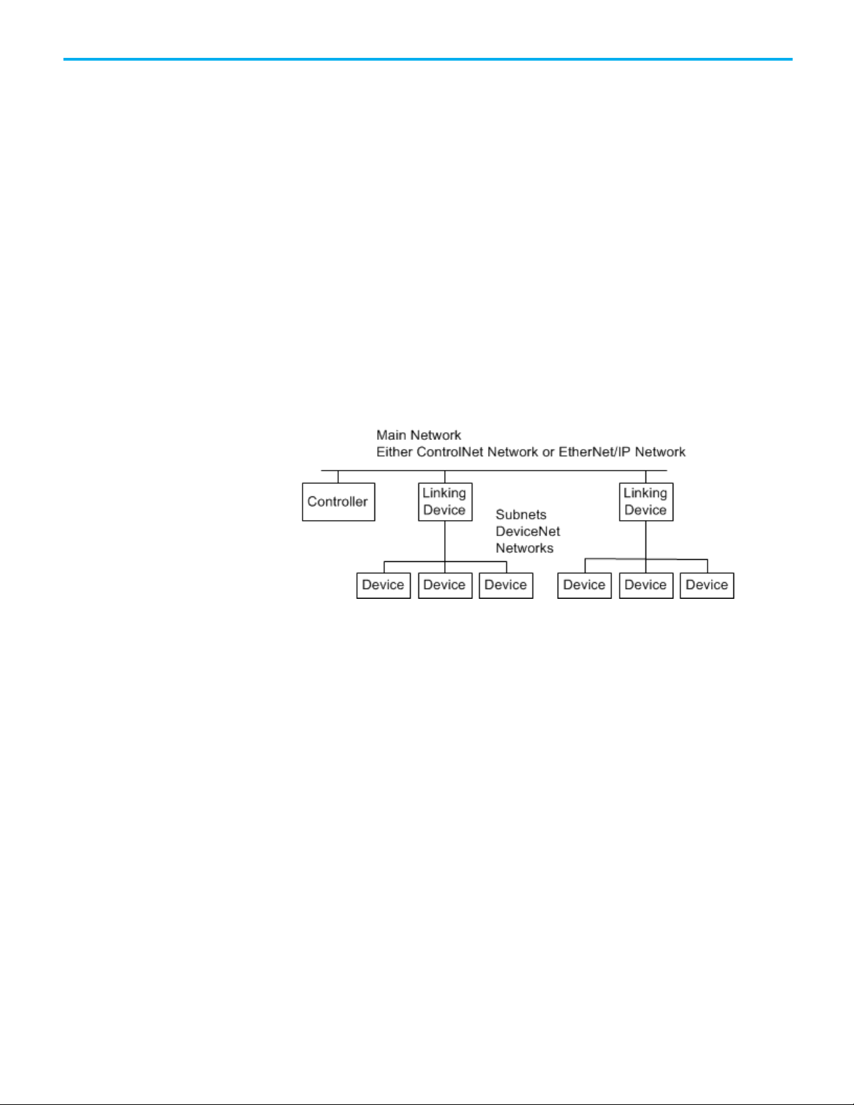
A subnet configuration is a main network that is connected to distributed
subnets using a scanner, or linking device. In this option, you must install a
ControlNet network or EtherNet/IP network, also known as a backbone, that
connects to distributed subnets using a linking device.
For example, if you choose an EtherNet/IP network backbone, you must use
1788-EN2DN linking devices to connect the subnets.
The following graphic shows a subnet network.
Subnets
Subnets
There are advantages to using subnets for your DeviceNet application:
• Typically, there are shorter runs on subnets, which allow a faster
communication rate for the DeviceNet network.
• With fewer devices on each subnet, the overall performance of the
network is faster.
• There are simpler power requirements.
There are disadvantages to using subnets for your DeviceNet application:
• The overall cost to install the network is higher than using a single
network.
• You must manage multiple networks.
• The Logix5000 controller is remote from the linking device. For
example, with subnets in a 1768 CompactLogix application, a 1768-L45
controller is remote from the 1788-CN2DN linking device.
The DeviceNet scanner connects a Logix5000 controller to the devices on a
DeviceNet network. The following graphic shows how a scanner exchanges
data between a controller and devices on the DeviceNet network.
16 Rockwell Automation Publication DNET-UM004D-EN-P - September 2020
Page 17
If you are using
And
Use this scanner
DriveLogix controller
1788-DNBO DeviceNet daughtercard
IMPORTANT
Refer to table Bridging Across Networks on page 17 for more information.
Bridge Across Networks
Chapter 1 DeviceNet Overview
The following table describes how to choose a scanner.
Single network 1768 or 1769 CompactLogix controller CompactLogix 1769-SDN modules
ControlLogix controller ControlLogix 1756-DNB modules
SoftLogix 5800 controller 1784-PCIDS card
Subnets EtherNet/IP main network EtherNet/IP to DeviceNet Linking Device 1788-EN2DN
ControlNet main network ControlNet to DeviceNet Linking Device 1788-CN2DN
Logix5000 controllers can usually communicate with devices on other
networks with no additional configuration or programming. A bridge
connects two networks.
You cannot bridge from a device on a DeviceNet network to a device on a ControlNet
nor EtherNet/IP network. You can only bridge from devices on ControlNet or
EtherNet/IP networks to devices on DeviceNet networks.
The bridge is one of the following:
• A single device with communication ports for two different networks,
such as a 1788-EN2DN linking device
• A separate communication device in the same chassis
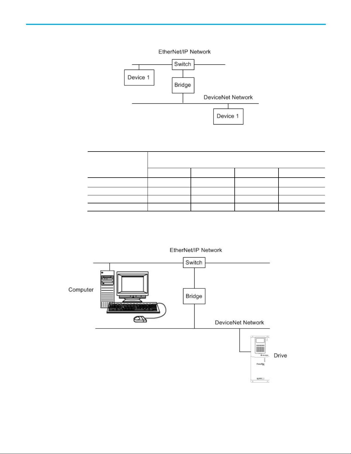
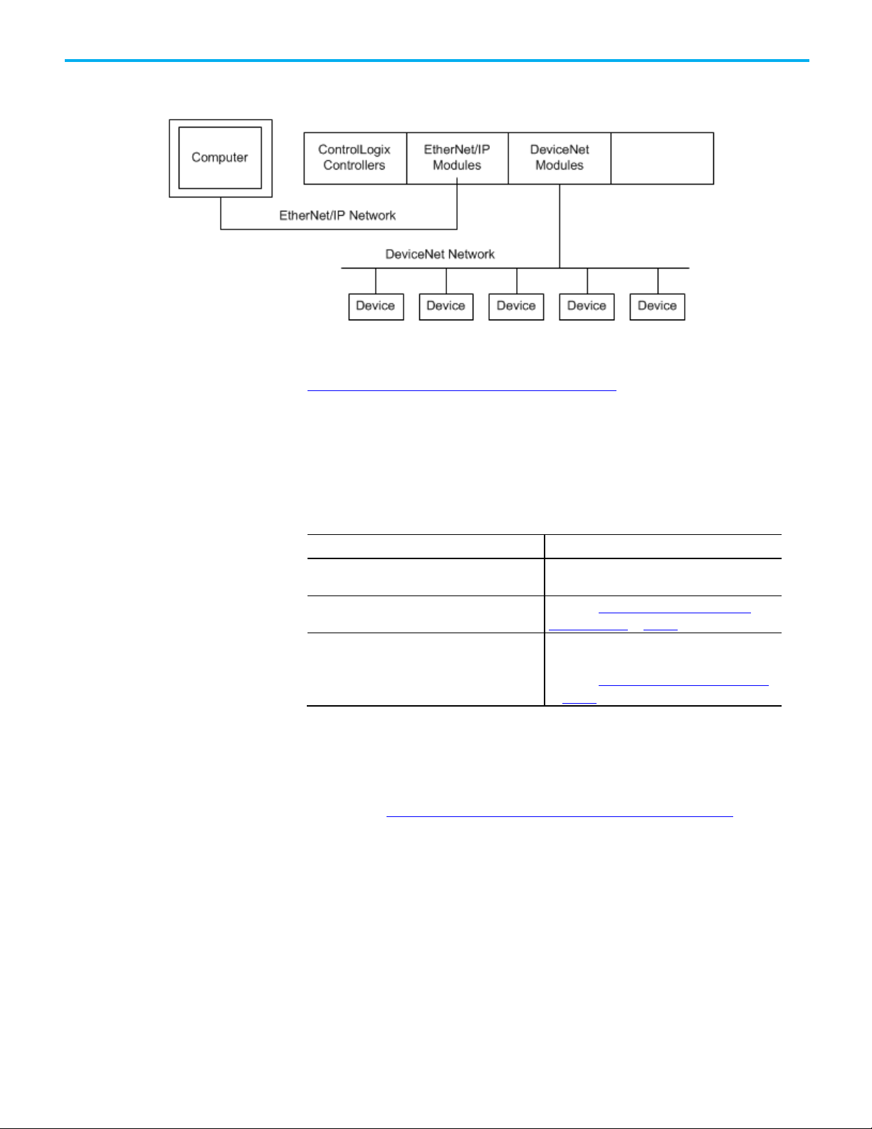
For example, the bridge device shown in the following graphic is connected to
both EtherNet/IP and DeviceNet networks. Device 1 on an EtherNet/IP
Rockwell Automation Publication DNET-UM004D-EN-P - September 2020 17
Page 18
Chapter 1 DeviceNet Overview
A device on this network
EtherNet/IP
ControlNet
DeviceNet
RS-232(1)
ControlNet
yes
yes
yes
yes
EtherNet/IP yes yes yes yes
network can communicate with Device 2 on a DeviceNet network through the
bridge.
The following table describes how communication can bridge the networks.
Bridging Across Networks
Can access a device on this network
DeviceNet no no yes no
RS-232 yes yes(2) yes yes
In this example, a computer configures a drive on a DeviceNet network. The
workstation bridges an EtherNet/IP network to reach the drive.
18 Rockwell Automation Publication DNET-UM004D-EN-P - September 2020
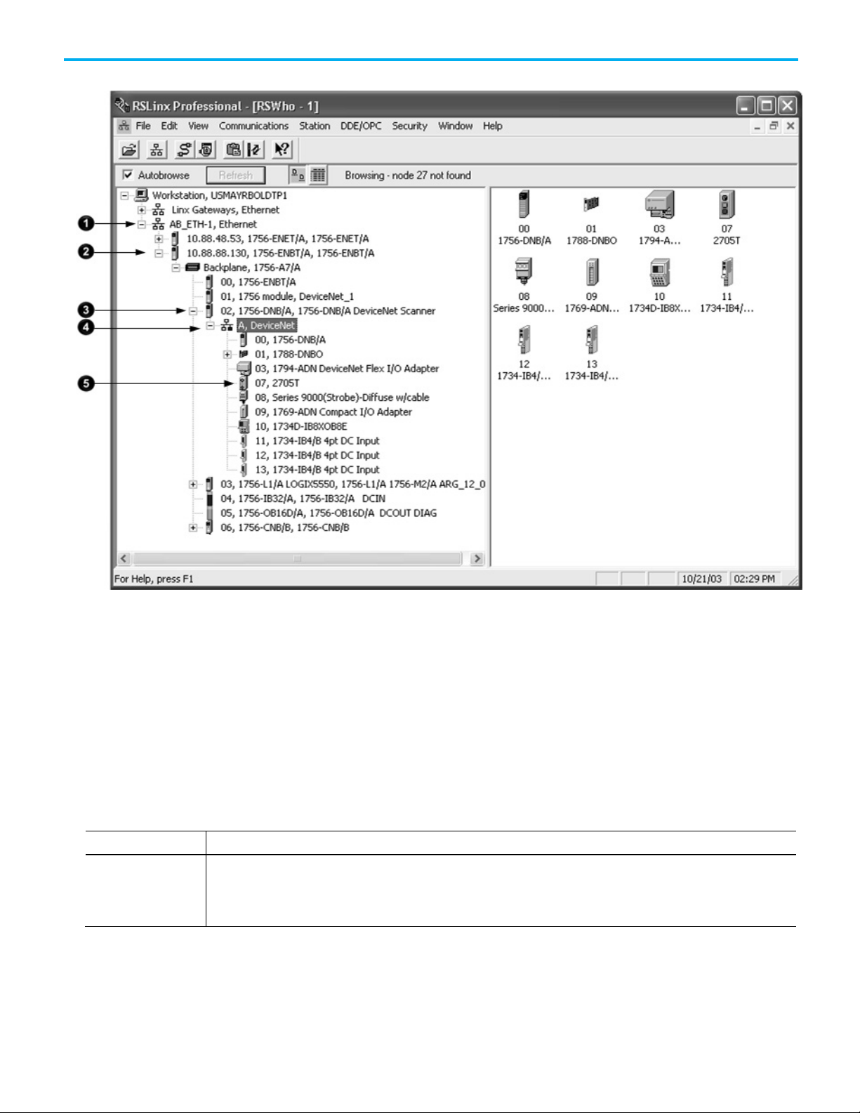
In this example, the RSLinx communication software window shows how the
DeviceNet bridge links to the EtherNet/IP network.
Page 19
Method
Description
Typically, scanners and network interfaces have a fixed baud rate.
Choose a Baud Rate for the
Chapter 1 DeviceNet Overview
You must choose a baud rate for the DeviceNet network. There are three rates
available for the network:
Network
• 125 kbps—This is the default baud rate for a DeviceNet network. It is
the easiest baud rate to use and is usually sufficient.
• 250 kbps
• 500 kbps
The following table describes the most common methods to set a baud rate.
Autobaud feature At powerup, the device automatically sets its baud rate to the baud rate of the first device it hears on the network. The baud rate
remains set until the device powers up again.
The network requires at least one device with a fixed baud rate so the autobaud devices have something against which to set.
Rockwell Automation Publication DNET-UM004D-EN-P - September 2020 19
Page 20
Chapter 1 DeviceNet Overview
Method
Description
baud rate.
Baud Rate
Cumulative Drop Line Length
Flat Cable
Thick Cable
Thin Cable
250K bit/s
200m (656 ft)
250m (820 ft)
100m (328 ft)
78m (256 ft)
500K bit/s
75m (246 ft)
100m (328 ft)
100m (328 ft)
39m (128 ft)
If a device
Then
2. Connect the device to the network.
Assign an Address to Each
Switches or push button
on the device
Software Some devices require a programming device to set its address. For example, you can use the computer and the DeviceNet node
Some devices have switches or push buttons that set the baud rate as follows:
• The device reads the switch setting at powerup.
• Typically, the switch lets you select either autobaud or a fixed baud rate, that is 125 Kbps, 250 Kbps, or 500 Kbps
• If you change the switch setting, you must cycle power to the device before the change takes effect.
There are exceptions. For example, the 1756-DNB module has a push button that only lets you set the baud rate if the module is
disconnected from the network or network power is off. Once you change the baud rate, the module automatically resets to the new
commissioning tool to set the baud rate of a device. The node commissioning tool is available in either of the following methods:
• Automatically when you install RSNetWorx for DeviceNet software
• As a separate application on the RSLogix 5000 programming software CD, revision 13.0 or later
The length of the trunkline and type of cable determines which baud rates you
can use.
Maximum Distance
125K bit/s 420m (1378 ft) 500m (1640 ft) 100m (328 ft) 156 m (512 ft)
Device
If you change the baud rate of the network, make sure that all devices change
to the new baud rate. Mixed baud rates produce communication errors.
Complete the following steps to set the baud rate for the network.
1. Connect the network interface to the network and set its baud rate.
2. Connect the scanner to the network and set its baud rate.
3. For each device that has only fixed baud rates (no autobaud), set the
baud rate and connect it to the network.
4. Connect the remaining devices to the network and enable autobaud
for each of them.
has a switch to enable autobaud 1. Set the switch to autobaud.
does not have a switch to enable autobaud 1. Connect the device to the network.
2. Use RSNetWorx for DeviceNet software to enable autobaud.
To communicate on the DeviceNet network, each device requires its own
address. In general, a device can use any address in the range of 0…63.
However, we recommend that you follow the guidelines in the following table.
20 Rockwell Automation Publication DNET-UM004D-EN-P - September 2020
Page 21

Give this device
This address
Notes
• The auto-address recovery feature also requires address 63 to be open.
Required Software
Scanner 0 If you have multiple scanners, give them the lowest addresses in sequence (0, 1…).
Any device on the network
except the scanner
Computer interface to the
network
No device 63 Always leave address 63 open. Out of the box, most DeviceNet devices are preset for address 63.
1…61 • Give the lower addresses to devices with 15 bytes or more of input or output data.
• Gaps between addresses are OK and have no effect on system performance. If you are uncertain of the
final lay-out of your system, leave gaps between addresses. This gives you some flexibility as you
develop your system.
62 If you connect a computer directly to the DeviceNet network, use address 62 for the computer.
• Many computer interface devices use this address as their default.
• The 1784-U2DN device can connect a computer directly to a DeviceNet network.
• Some devices have no switches or push button to set the address. They require software, such as
RSNetWorx for DeviceNet software to change the address. This means that you must first place it on
the network at its preset address of 63 before you can change the address.
• If another device is already using address 63, there will be an address conflict and you won’t be able to
communicate with the newly connected device.
• Leaving address 63 open makes it possible to configure a new device.
Refer to Chapter 3 on page 29 for more information on how to assign an
address to each device.
Chapter 1 DeviceNet Overview
You must use the correct software with the DeviceNet application.
• To connect your computer to the DeviceNet network, use RSLinx
communication software.
• To program the Logix5000 controller, use Logix Designer application.
• To the configure the DeviceNet network, use RSNetWorx for
DeviceNet software.
Rockwell Automation Publication DNET-UM004D-EN-P - September 2020 21
Page 22

Page 23
Topic
Page
Connection Options
Chapter 2
Connect a Computer to the DeviceNet Network
This chapter shows how to connect a computer to the network. After you
physically connect a computer to the network, you must configure a driver in
RSLinx communication software to communicate over the network.
Connection Options on page 23 26 on page 23
Set Up the DeviceNet Driver on page 24 27 on page 24
After you connect a computer to the network and configure a driver in RSLinx
communication software, you can complete these tasks:
• Configure the devices on the network
• Configure network parameters
• Upload, download, monitor, and program projects for Logix5000
controllers
Some networks let you bridge to other networks in your system. This lets you
connect to one network and access devices or controllers on other networks.
To access the DeviceNet network, do one of the following:
• Connect directly to the network via the 1784-U2DN interface device. If
you connect directly to a DeviceNet network, you can access only the
devices on that network. If you use this method, refer to
Set Up the
DeviceNet Driver on page 27 on page 24.
The following graphic shows a computer connected directly to a DeviceNet
network.
Rockwell Automation Publication DNET-UM004D-EN-P - September 2020 23
• Connect to a different network and bridge to the desired DeviceNet
network. This requires no additional programming.
Page 24
Chapter 2 Connect a Computer to the DeviceNet Network
RSLinx Classic Software Version
Action
U2DN interface device.
Device on page 27 on page 24.
Set Up the DeviceNet Driver
Obtain the Driver for the
Verify that the Driver Works
The following graphic shows a computer connected to a DeviceNet network
through an EtherNet/IP network used with a ControlLogix system.
For more information about installing modules on the DeviceNet network,
refer to the Rockwell Automation Literature Library at:
http://www.rockwellautomation.com/literature/
To find the installation publications specific to your module, search by the
module’s catalog number.
.
Interface Device
The requirements for setting up the DeviceNet driver depend on your version
of RSLinx Classic software.
2.50 or earlier Upgrade to version 2.51 or later to use the 1784-
2.51, 2.52, or 2.53 Proceed to Obtain the Driver for the Interface
2.54 or later The 1784-U2DN interface device driver is already
installed on the computer.
Proceed to Verify that the Driver Works on page 27
on page 24.
Follow these steps to download and install the device driver for the 1784U2DN interface device.
1. Visit http://www.rockwellautomation.com/knowledgebase/
.
2. Open tech note ID 53280 and follow the instructions to install the
driver.
24 Rockwell Automation Publication DNET-UM004D-EN-P - September 2020
Complete the following steps to verify that the driver for the 1784-U2DN
interface device works.
1. Open RSLinx Classic software.
Page 25
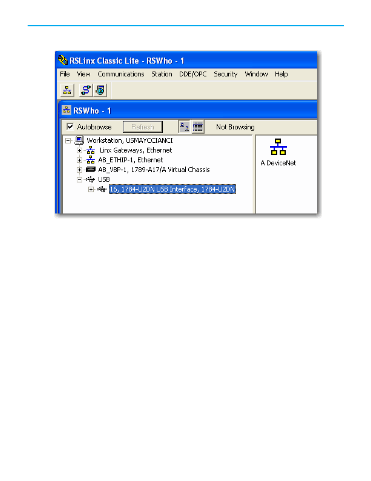
2. Click the Browse button and verify that the 1784-U2DN interface
appears under USB.
Chapter 2 Connect a Computer to the DeviceNet Network
Rockwell Automation Publication DNET-UM004D-EN-P - September 2020 25
Page 26

Page 27
Before You Begin
Set the Node Address of a
Chapter 3
Connect Devices to the Network
This chapter describes how to connect a device to the network and set the
device’s address so it can communicate on the DeviceNet network.
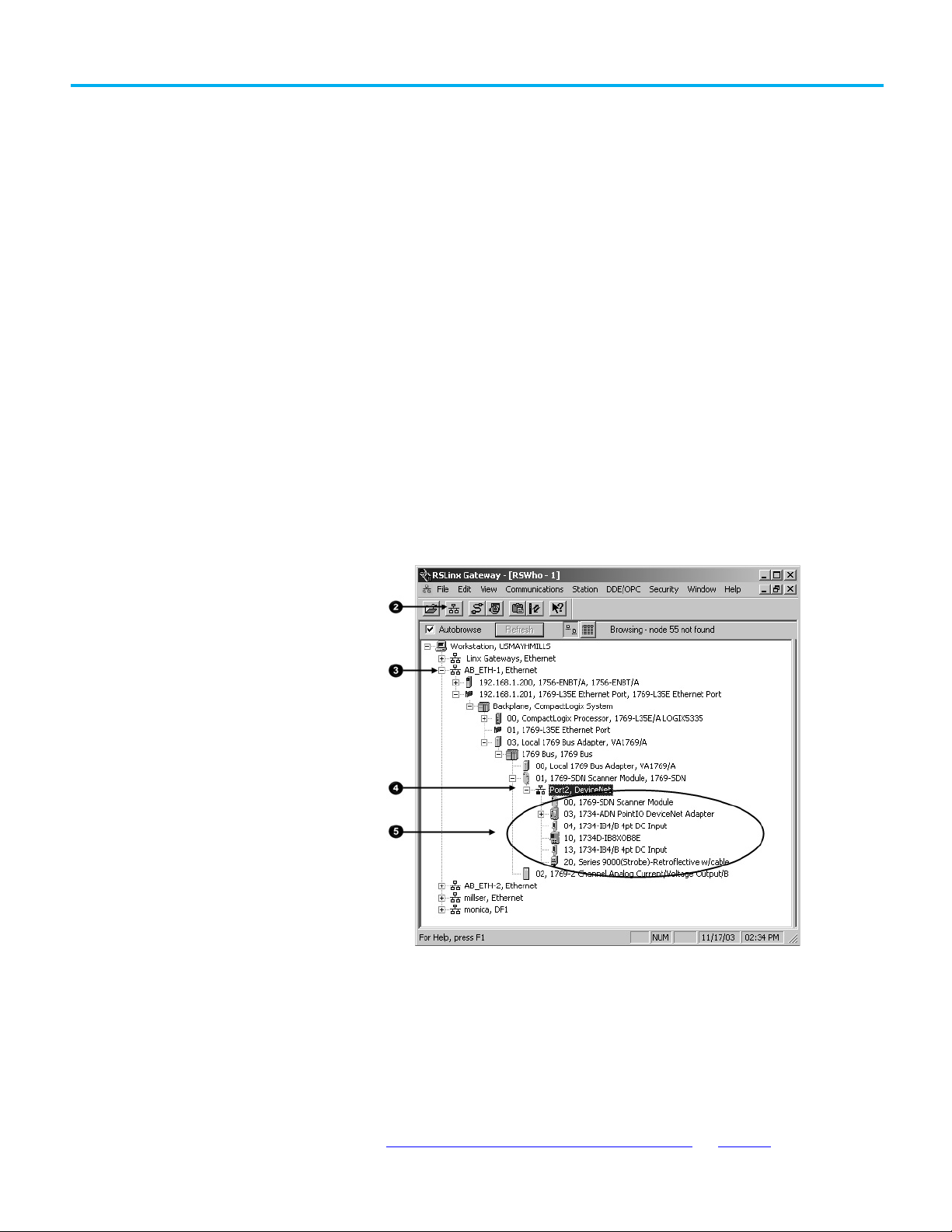
Before you use this chapter, make sure that you can see all your devices on the
DeviceNet network. Complete the following steps to see your DeviceNet
network.
1. Start RSLinx communication software.
2. Browse the network.
3. Expand a driver that lets you access the DeviceNet network.
4. Select the DeviceNet network.
5. Verify that you see all the devices that are connected to the DeviceNet
network.
Device
Rockwell Automation Publication DNET-UM004D-EN-P - September 2020 27
You can use the following options to set the node address of DeviceNet
devices. However, not all options apply to every DeviceNet device.
For example, you can use all three options with the 1756-DNB ControlLogix
DeviceNet scanner, but you can use only the second and third methods with
the 1769-SDN Compact I/O DeviceNet scanner.
• Set Node Address via Hardware Mechanism on page 28
Page 28
Chapter 3 Connect Devices to the Network
Give this address
To this device
conflicting with another device.
Mechanism
Graphic
Description
device for the change to take effect.
IMPORTANT
to set the node address.
Set Node Address via
All DeviceNet devices ship with their node addresses set to 63. To avoid
duplicate node number conditions on the network, you should change the
node address for each device to a unique number as you add it to the network.
For more information about setting the node address of DeviceNet devices,
refer to the Rockwell Automation Literature Library at:
http://www.rockwellautomation.com/literature/
• Set Node Address via Software on page 29
• Set Node Address via DeviceNet Node Commissioning Tool on page 30
0 Scanner
1…61 Devices
62 Computer interface to the network, such as a 1784-U2DN device
63 None
Out of the box, a DeviceNet communication module is preset for address 63.
Leaving address 63 open lets you get a new device on the network without
.
Hardware Mechanism
To find the publications specific to your module, search by the module’s
catalog number.
Many DeviceNet devices have a hardware mechanism that you can use to set
the node address. If a device has a hardware mechanism to set the node
address, use that mechanism.
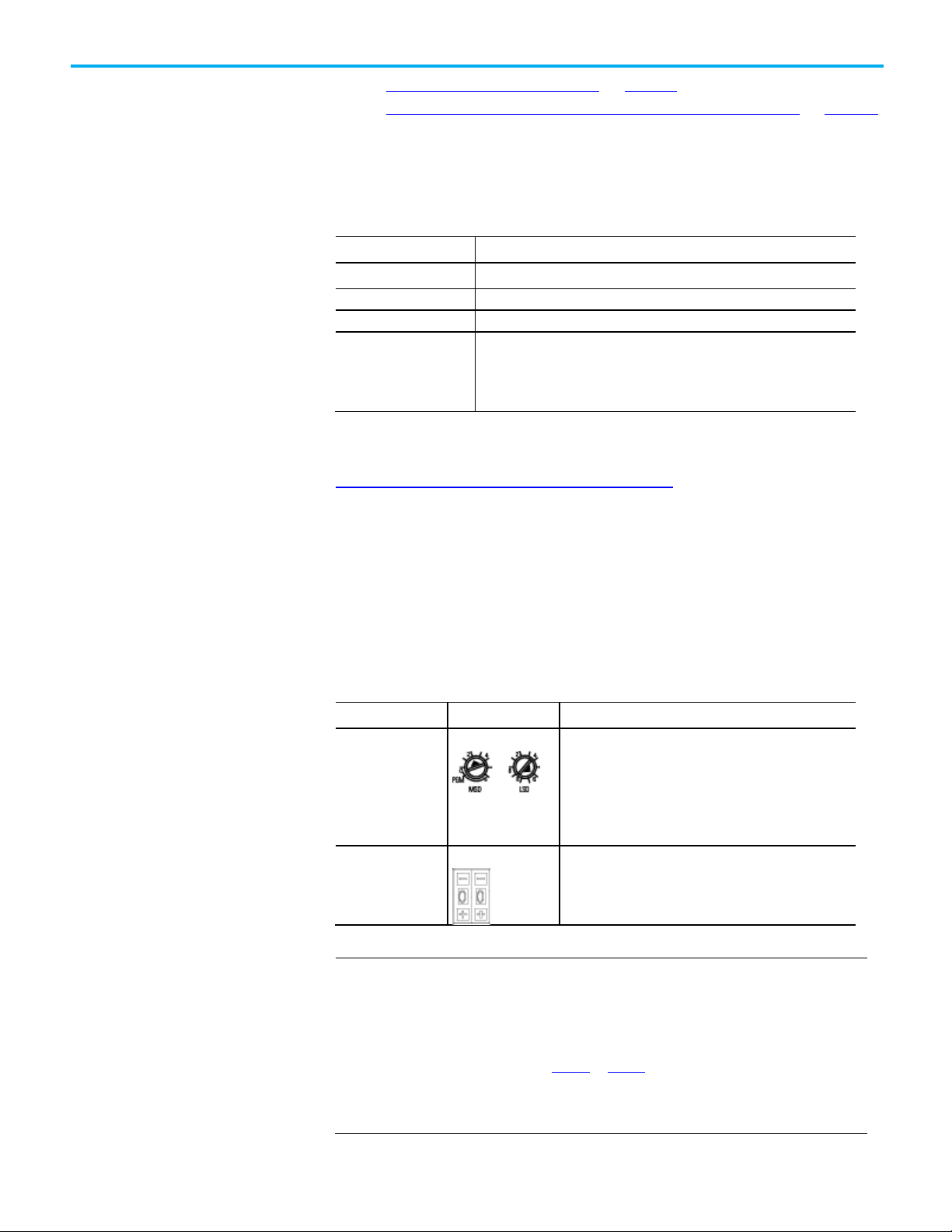
The following table describes the two most common hardware mechanisms.
Rotary switch
Push-wheel switch
As long as a device’s hardware mechanism sets the node address to 63 or lower, you
cannot change the node address with RSNetWorx for DeviceNet software or the
DeviceNet node commissioning tool.
Make sure each device’s node address set by a hardware mechanism matches the
node address used in your RSNetWorx for DeviceNet software network configuration
file, as described on page 40 on page 36
However, if you set a device’s hardware mechanism to a number higher than 63, you
can use RSNetWorx for DeviceNet software or the DeviceNet node commissioning tool
You turn the dials of rotary switches to specific numbers
that represent the device’s node address.
You usually need a small flathead screwdriver to turn the
switches. A device reads the switches when you power it up.
If you change the address, you should cycle power to that
You set the numbers on the push-wheel switch to specific
numbers that represent the device’s node address.
.
28 Rockwell Automation Publication DNET-UM004D-EN-P - September 2020
Page 29

IMPORTANT
IMPORTANT
page 37.
Set Node Address via
Chapter 3 Connect Devices to the Network
You must cycle power to the module for node changes set through hardware to take
effect.
You can set a device’s node address in RSNetWorx for DeviceNet software.
Software
Setting a device’s node address is only one task used when configuring a device with
RSNetWorx for DeviceNet software.
For complete information on how to configure all parameters with RSNetWorx for
DeviceNet software, including setting a device’s node address, refer to Chapter 4 on
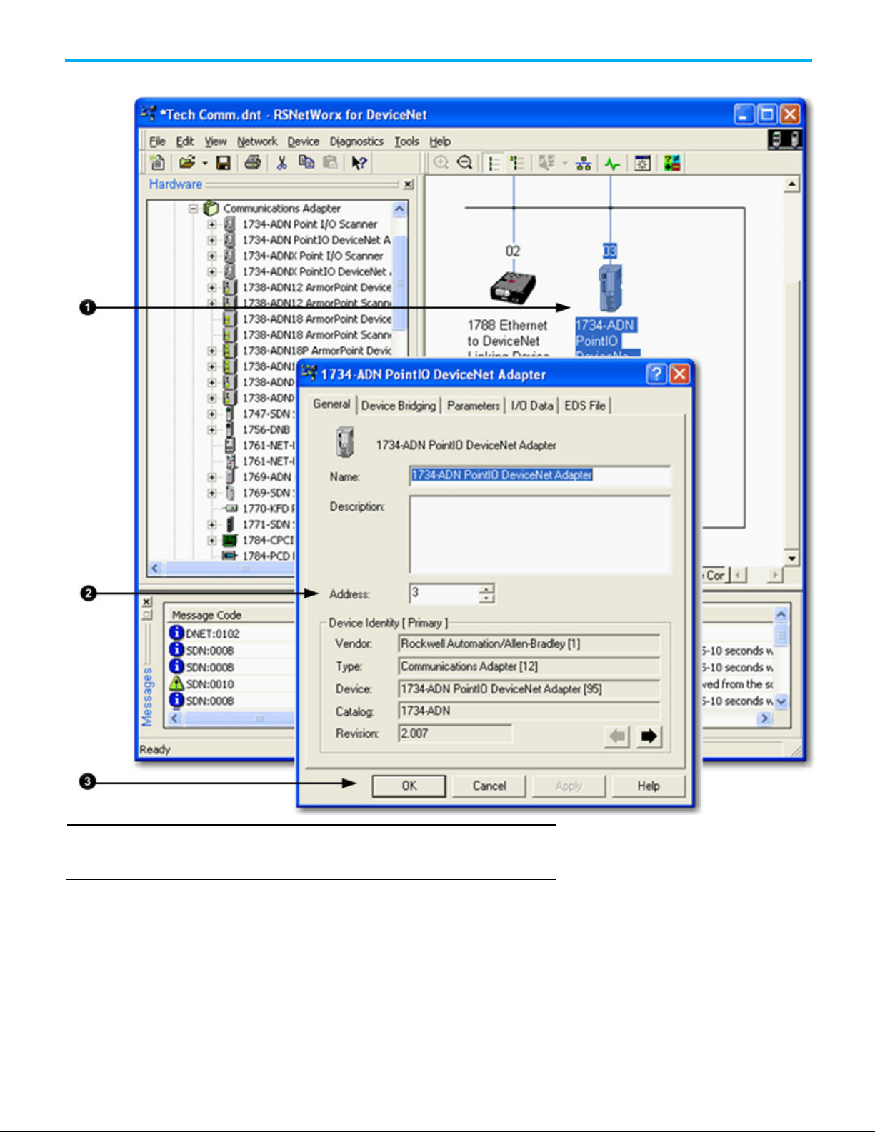
Complete the following steps to set a device’s node address in your network
configuration file. This example uses an AC drive.
1. Double-click the device.
2. Enter the DeviceNet address for the device.
Rockwell Automation Publication DNET-UM004D-EN-P - September 2020 29
Page 30
Chapter 3 Connect Devices to the Network
IMPORTANT
Set Node Address via
3. Click OK to close the configuration window.
The node address assigned by RSNetWorx for DeviceNet software only takes effect if
the device does not have a hardware mechanism to set the node address or if the
device has its hardware mechanism set to a number higher than 63.
DeviceNet Node
Commissioning Tool
30 Rockwell Automation Publication DNET-UM004D-EN-P - September 2020
You can use the DeviceNet node commissioning tool available in RSNetWorx
for DeviceNet software to set the node addresses of devices on the DeviceNet
network. Remember the following when you decide to use the DeviceNet
node commissioning tool.
• You can only use this tool with a DeviceNet network that is online.
Page 31

Chapter 3 Connect Devices to the Network
• You can only use this tool as you add new devices to the network that
either do not have hardware mechanisms to set their node address or
have their hardware mechanism set to a number higher than 63.
If you add a device to the network with a hardware mechanism setting the
node address to 63 or lower, this tool does not change the device’s node
address.
• You should complete the tasks described in this section each time a
new device is added to the network.
• If you add more than one device to the online network before using the
DeviceNet node commissioning tool, you will experience duplicate
node address conflicts on the network because all new devices initially
use node address 63.
• Keep track of the node addresses you set with the DeviceNet node
commissioning tool and verify they match the device’s configuration
in the RSNetWorx for DeviceNet software configuration file.
Complete the following steps to use the DeviceNet node commissioning tool
to set a device’s node address. This example uses the 1769-SDN Compact I/O
DeviceNet Scanner module.
1. Verify that the network is online.
2. Connect a device to the DeviceNet network.
3. Choose Start>Programs>Rockwell Software>RSNetWorx for
DeviceNet>DeviceNet node commissioning tool.
or
From the Tools pull-down menu in RSNetWorx for DeviceNet
software, choose Node Commissioning.
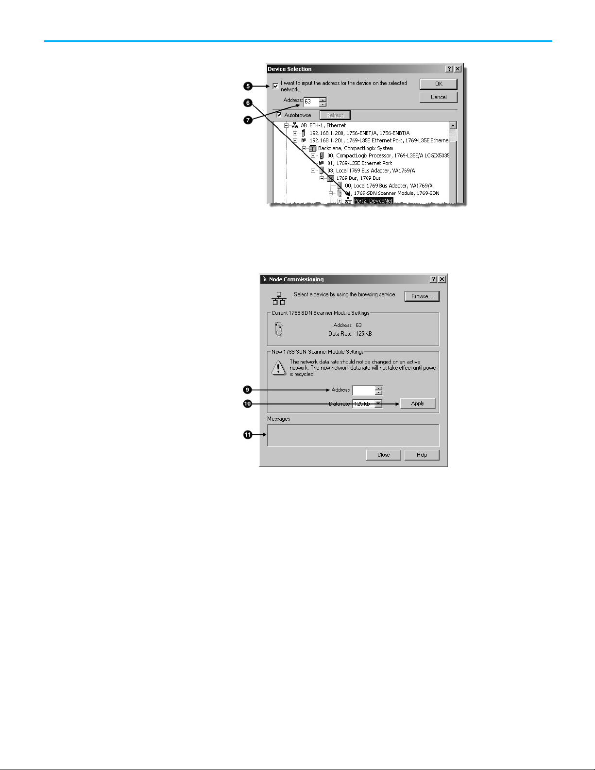
4. Click Browse.
5. On the Device Selection dialog box, check the ‘I want to input the
address for the device on the selected network’ box.
6. Browse to the DeviceNet network.
7. Type the current address for the device. Out of the box, devices use
address 63.
Rockwell Automation Publication DNET-UM004D-EN-P - September 2020 31
Page 32
Chapter 3 Connect Devices to the Network
Make Sure Your Devices Are
8. Click OK.
9. When you return to the Node Commissioning dialog box, enter the
new address for the device.
10. Click Apply.
11. Look for confirmation.
on Your Network
32 Rockwell Automation Publication DNET-UM004D-EN-P - September 2020
12. If you need to use the DeviceNet node commissioning tool to set
another device’s node address, return to step on page 34 and repeat
the process.
Once you have assigned a node address to each device, make sure that the
devices are communicating on the network. Complete these steps to make
sure your devices are on the network.
1. Start RSLinx communication software.
2. Go online.
3. Expand a driver that lets you access the DeviceNet network.
4. Browse to the DeviceNet network.
5. Make sure you see all the devices that are connected to the DeviceNet
network.
Page 33
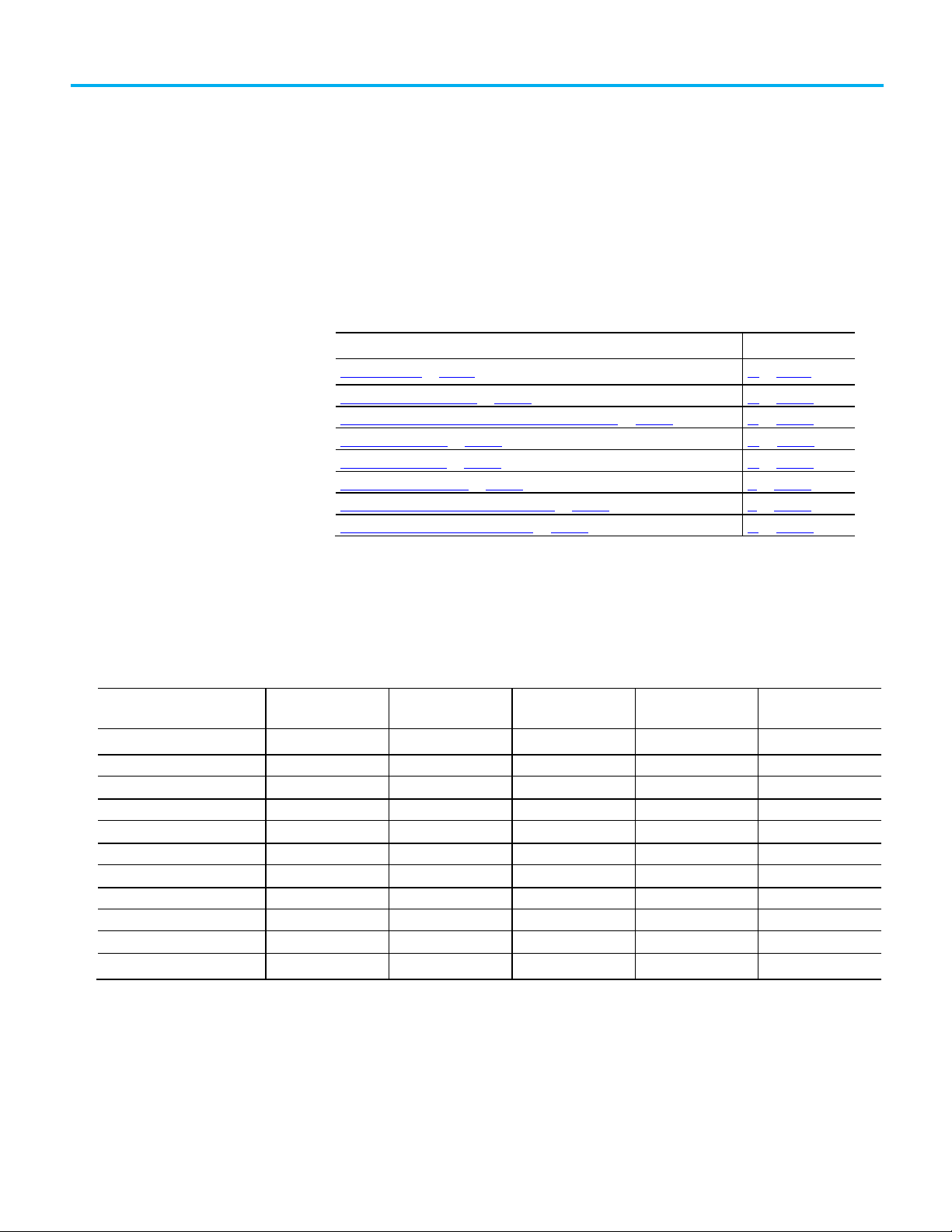
Topic
Page
Create Your Network in RSNetWorx for DeviceNet Software on page 34
39 on page 34
Configure Each Device on page 35
40 on page 35
Configure the Scanner on page 39
44 on page 39
Save the Configuration File on page 45
51 on page 45
Generate an RSNetWorx for DeviceNet Report on page 45
51 on page 45
Download Configuration to Your Network on page 49
55 on page 49
Device
Address
Input Size of Device
Input Memory in
Output Size of Device
Output Memory in
PanelView terminal
3
128
32
128
32
2
I/O adapter w/ modules
5 9 3 5 2
2
drive 7 4 1 4
1
2
photoeye
9 1 1 0 0
computer interface
62
n/a
n/a
n/a
n/a
Before You Begin
Create a File for the
Chapter 4
Configure the Network Offline
This chapter describes how to configure the network offline with RSNetWorx
for DeviceNet software.
Before You Begin on page 51 38 on page 51 Create a File for the Network on page 33 38 on page 33
Before you configure the DeviceNet network, make sure you have a list of the
devices that you put on the DeviceNet network and, at minimum, the address
for each. The following table shows an example list of devices.
(Bytes)
scanner 0 n/a n/a n/a n/a
<empty>
<empty>
<empty>
63
Total
Scanner (DINTs)
43
(Bytes)
Scanner (DINTs)
2
2
2
41
Network
Rockwell Automation Publication DNET-UM004D-EN-P - September 2020 33
Complete the following steps to create a DeviceNet configuration file.
1. Start RSNetWorx for DeviceNet software.
2. Create a file.
Page 34

Chapter 4 Configure the Network Offline
Create Your Network in
3. Select DeviceNet Configuration.
4. Click OK.
5. Save the file.
Make sure you give the file a name that identifies this specific
DeviceNet network.
RSNetWorx for DeviceNet
Software
Before you configure a DeviceNet communication module in RSNetWorx for
DeviceNet software, you must add it to the network configuration file.
The finished picture should match the collection of devices that are or will be
physically connected to the DeviceNet network. If the network configuration
file you create offline does not match the physical collection of devices on the
network, you may experience issues when you go online with your project.
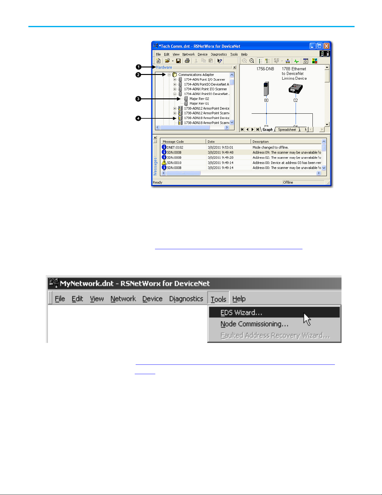
Complete the following steps to add each device to network configuration file.
1. Browse the hardware list for the device.
2. If there is a [+] sign next to the device, click the sign to expand the
choices in that section.
3. Double-click the major revision of the device.
We recommend that the major revision of all devices added to the
offline network match the devices that will be connected to the online
network.
4. For a device without a list of major revisions, that is, no [+] or [-] sign,
double-click the device.
34 Rockwell Automation Publication DNET-UM004D-EN-P - September 2020
Page 35
Configure Each Device
Chapter 4 Configure the Network Offline
If the hardware list does not show a device, then RSNetWorx for DeviceNet
software requires the EDS file for the device.
To add an EDS file, follow these steps.
1. To see if an EDS file is available, go to the following site:
http://www.rockwellautomation.com/resources/eds/
2. Use the EDS wizard of RSNetWorx for DeviceNet software to register
the file and see it.
After adding devices to the network configuration file, as described in
Create Your Network in RSNetWorx for DeviceNet Software on page 39
page 34, you configure parameters for each device to define the modules’
behavior.
on
Rockwell Automation Publication DNET-UM004D-EN-P - September 2020 35
Page 36

Chapter 4 Configure the Network Offline
IMPORTANT
Refer to Configure the Scanner on page 44 on page 39 for more information.
Give this address
To this device
You can configure most devices as you add them to the network configuration file or
you can add all the devices and then configure them.
Typically, you add a network scanner to the network first. In this case, we recommend
that you add all devices to the network configuration file before configuring the
scanner. Multiple parameters that need to be configured in the scanner’s
configuration, for example, building a scan list, require you to choose from devices on
the network.
Complete these tasks when configuring DeviceNet communication modules:
Specify a Device Node Address
• Specify a Device Node Address on page 36
• Configure Device Parameters on page 38
The following options are available to set a device’s node address:
• Hardware mechanism, as described on page 30 on page 28
• RSNetWorx for DeviceNet software, as described in this chapter
• DeviceNet node commissioning tool, as described on page 33 on
page
30
All DeviceNet devices ship with their node addresses set to 63. To avoid
duplicate node number conditions on the network, you should change the
node address for each device to unique numbers.
0 Scanner
1…61 Your devices
62 Computer interface to the network, such as a 1784-U2DN device
63 None
Out of the box, a DeviceNet communication module is preset for address 63.
Leaving address 63 open lets you get a new device on the network without
conflicting with another device.
When you create your network in RSNetWorx for DeviceNet software, as
described on page 39 on page 34
addresses based on the order in which they were added to the network. The
number appears below the device’s graphic on the screen as shown below.
36 Rockwell Automation Publication DNET-UM004D-EN-P - September 2020
, devices are automatically assigned node
Page 37

Change a Device Node
Chapter 4 Configure the Network Offline
As you create the network, consider the following:
• If you used a hardware mechanism to assign a node address for a
device, that number takes precedence over any number you assign in
RSNetWorx for DeviceNet software.
Make sure the numbers assigned by the hardware mechanism and in your
configuration file are the same for each device. For example, if the node
address for a 1756-DNB ControlLogix DeviceNet Scanner is set to 2 via a
hardware mechanism, but in the RSNetWorx for DeviceNet software
configuration file, the node address is 0, you need to change the address in the
software to 2.
Address
• The node addresses that are automatically assigned as you add devices
to the configuration file do not take effect when the project is offline.
• For devices that do not have hardware mechanisms, the node number
assigned in the network configuration file takes effect when you
download the project to the DeviceNet network, as described on
page
55 on page 49.
You may need to assign a device’s node address that is different from the
number automatically assigned when the device is added to the configuration
file. Complete the following steps to assign a device a specific node address.
1. Double-click the device.
Rockwell Automation Publication DNET-UM004D-EN-P - September 2020 37
Enter the node address for the device.
Page 38

Chapter 4 Configure the Network Offline
Configure Device
Complete the following steps to configure device parameters.
Parameters
1. Double-click the device to display the configuration dialog box.
2. Click the appropriate tab.
3. Set a parameter to the desired new value.
Typically, there are two methods to set a parameter:
• Choose a parameter from a pull-down menu
38 Rockwell Automation Publication DNET-UM004D-EN-P - September 2020
Page 39
Configure the Scanner
Chapter 4 Configure the Network Offline
• Type a new value
4. Click Apply to apply the change and leave the configuration dialog box
open, or click OK to apply the change and close the configuration
dialog box.
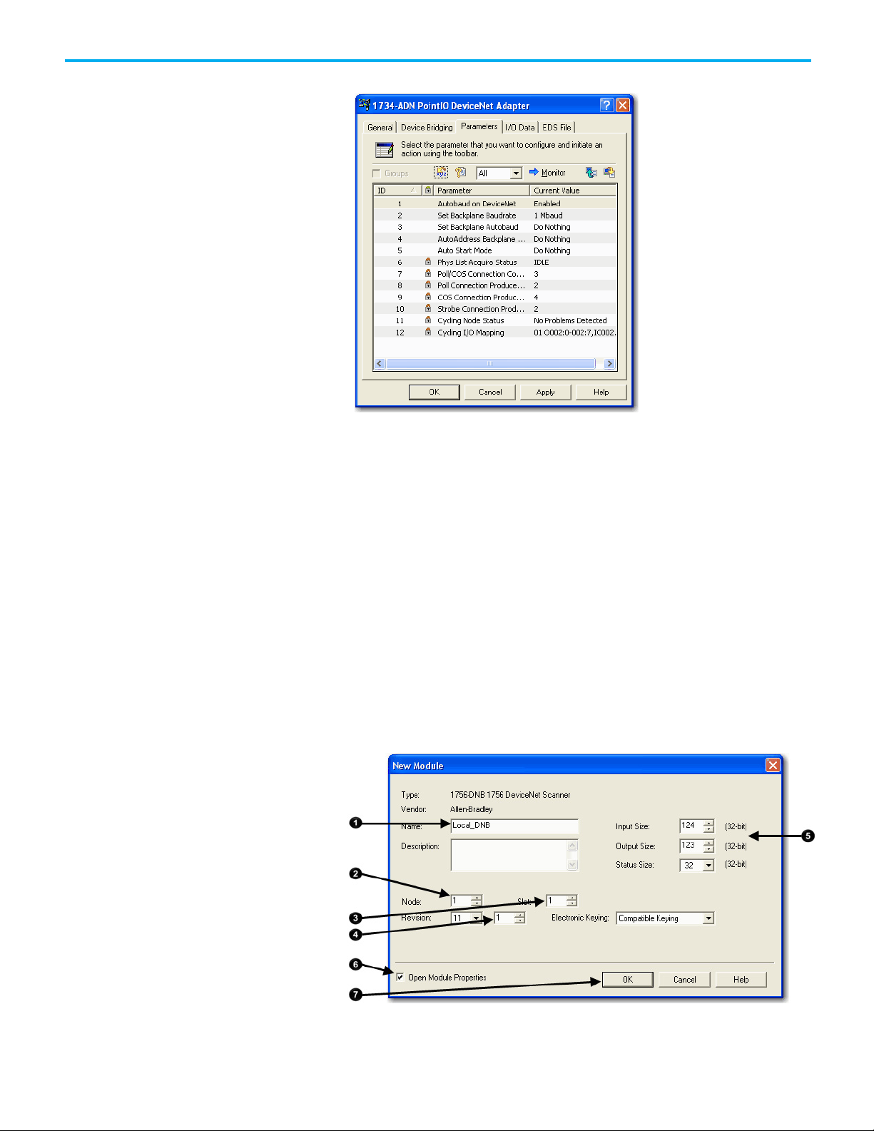
Complete the following steps to configure the scanner.
1. Type a name for the scanner.
2. Enter a node number.
3. Enter the slot number.
4. Enter the minor revision.
5. Enter the size of the input and output memory maps that the scanner
will allocate for each device it detects on the network.
Valid values range from 0…32 bytes per node.
6. If you need to make additional configuration changes, such as setting
the requested packet interval (RPI), check Open Module Properties.
7. Click OK.
Rockwell Automation Publication DNET-UM004D-EN-P - September 2020 39
8. If the Module Properties dialog box appears, make additional
configuration changes.
Page 40
Chapter 4 Configure the Network Offline
Build the Scan List
You can change scanner configuration on the following tabs:
• General
• Connection
• RSNetWorx
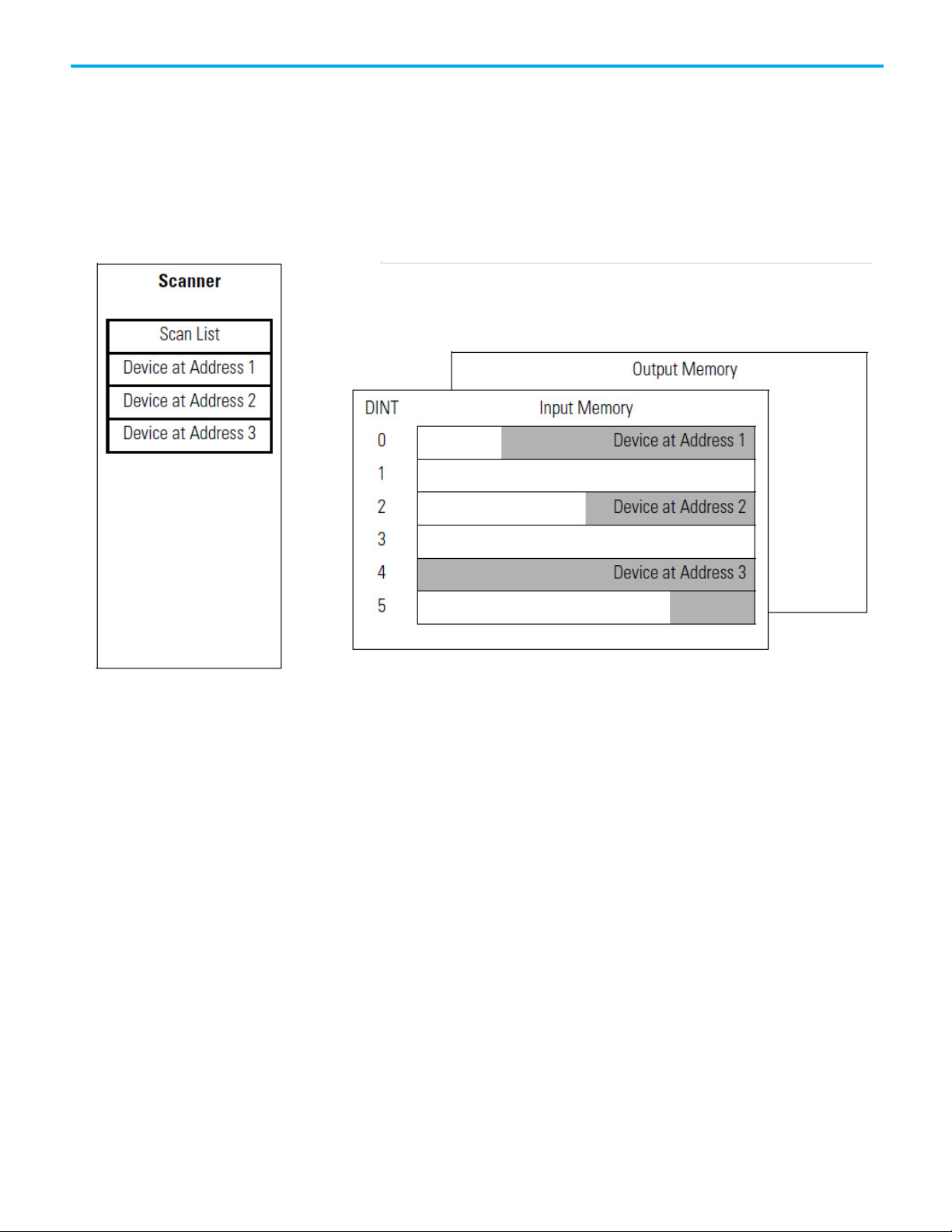
A scan list is a list of devices with which the scanner communicates. For each
device in the scanner’s scan list, the scanner sets aside input or output
memory for the data of the device.
Complete the following steps to build a scan list.
1. Double-click the scanner to open the configuration dialog box, or, if
the scanner configuration has already been uploaded and the
configuration dialog box is open, go to step 2.
2. Click the Scanlist tab. The devices on the network appear in the
Available Devices column.
40 Rockwell Automation Publication DNET-UM004D-EN-P - September 2020
Page 41
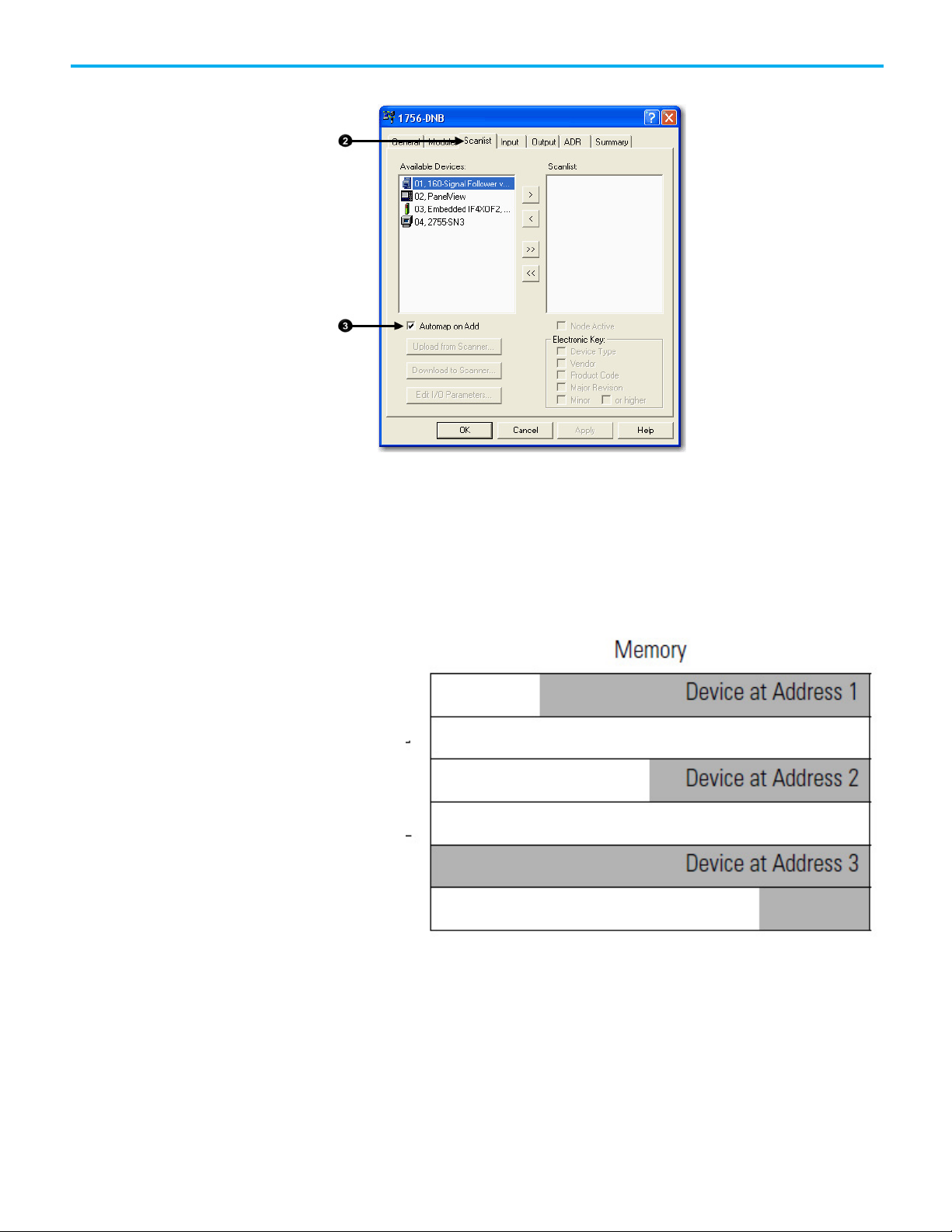
3. Clear or check Automap on Add.
RSNetWorx for DeviceNet software can automatically assign the
memory location for each device.
Chapter 4 Configure the Network Offline
• If you want to leave gaps between devices in the memory, as shown
below, clear the box.
Leave Gaps Between Devices
• If you want to place devices in sequential DINT’s, as shown below,
leave the box checked. When you check the box, the software
automatically assigns a memory location for each device as you add
it to the scan list.
Place Devices in Sequential DINTs
Rockwell Automation Publication DNET-UM004D-EN-P - September 2020 41
Page 42

Chapter 4 Configure the Network Offline
IMPORTANT
Set the Alignment Option
Move devices from the Available Devices column to the Scanlist
column.
If you get the following warning for a device, see
Set the I/O
Parameters of a Device on page 143 on page 167 on page 143.
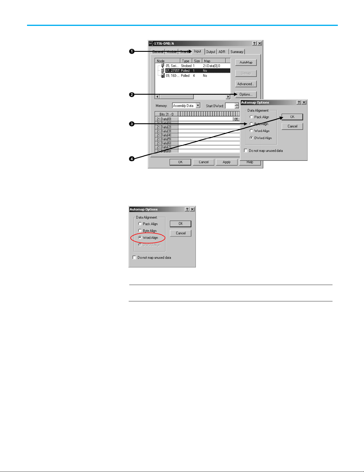
Choose a data alignment option to map the I/O data so that it is aligned on a
boundary, such as a byte, word, or double-word, or efficiently grouped
without alignment in the input or output memory map. To map I/O data so it
is grouped without alignment, click the Pack Align option.
The alignment option you choose applies to both the input and output maps.
Complete these steps to select an alignment option.
1. Click the Input tab.
2. Click Options.
3. Click the desired data alignment.
42 Rockwell Automation Publication DNET-UM004D-EN-P - September 2020
Page 43
IMPORTANT
SoftLogix 5800 Controller
Manually Assign Each
Chapter 4 Configure the Network Offline
4. Click OK to close the Automap Options dialog box.
The SoftLogix 5800 scanner 1784-PCIDS organizes its input and output
memory in 16-bit words. For that scanner, click the Word Align option.
Device to a Memory
Location
You can manually assign locations for device data.
If you configured the software to automatically assign memory locations as devices
are added, as described on page 45, skip this section.
1. Click the Input tab.
Rockwell Automation Publication DNET-UM004D-EN-P - September 2020 43
Page 44

Chapter 4 Configure the Network Offline
2. Select the device.
3. In the Start DWord field, enter the element number to which you want
to assign the data.
This is the starting point for the data. Larger data sizes wrap to several
elements. For example, to start the data in . . . Data[3], enter 3 in the
Start DWord box.
4. Click Automap.
An entry for the device appears in the input array.
5. Click the Output tab and repeat the steps above.
6. Click OK to complete the scanner configuration.
44 Rockwell Automation Publication DNET-UM004D-EN-P - September 2020
Page 45

Save the Configuration File
Generate an RSNetWorx for
Chapter 4 Configure the Network Offline
Sometimes, a specific input or output value may end up as the upper bytes of a
DINT in the scanner.
To make your programming easier, use advanced mapping to re-map the
value to its own memory location. For more information, see
Map the Memory
Location with Advanced Mapping on page 153 on page 184 on page 153.
After you make a change to the network, upload the entire network and save
the file. This makes sure that the offline configuration file matches the
network.
Complete these steps to save the configuration file.
DeviceNet Report
1. From the Network menu, choose Upload from Network.
2. When prompted, click Yes to upload the entire network.
3. Save the file.
An RSNetWorx for DeviceNet report shows these items:
• Devices on the network
• Memory addresses of those devices in the scanner
• Device configurations
The report is a useful reference when you program your system. Complete the
following steps to generate a report.
Rockwell Automation Publication DNET-UM004D-EN-P - September 2020 45
Page 46

Chapter 4 Configure the Network Offline
1. From the File menu in RSNetWorx for DeviceNet software, choose
Generate Report.
2. Click Generate report for entire network.
46 Rockwell Automation Publication DNET-UM004D-EN-P - September 2020
Page 47

The report appears in your web browser.
Chapter 4 Configure the Network Offline
Go Online to Your Network
When you go online, RSNetWorx for DeviceNet software browses the
network once and shows the devices currently on the network in the new
network configuration file.
Keep in mind the following when you go online:
• RSNetWorx for DeviceNet software does not read (upload) or change
(download) the parameters of any of the devices on the network.
• The picture that results from browsing remains static. It does not show
any changes since the last browse.
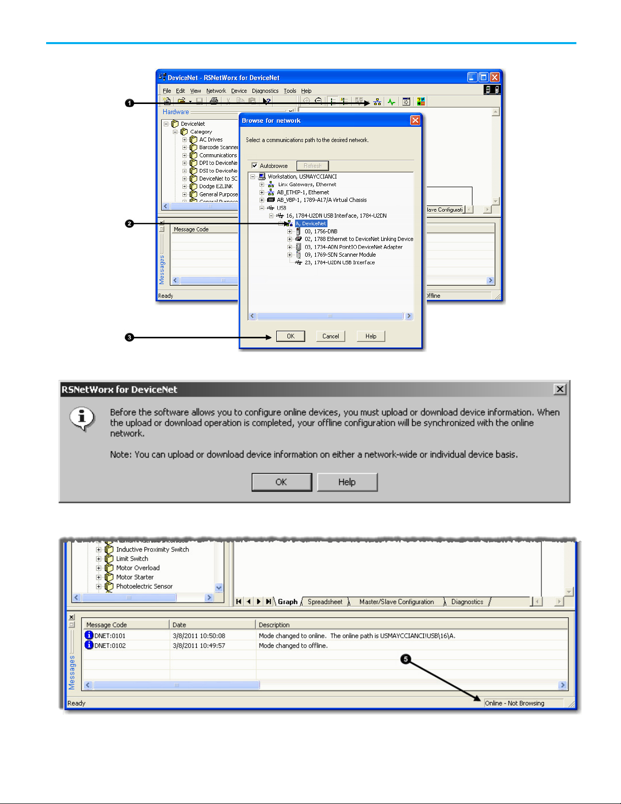
Complete the following steps to go online.
1. Click the Online button.
2. Select the DeviceNet network.
Rockwell Automation Publication DNET-UM004D-EN-P - September 2020 47
Page 48
Chapter 4 Configure the Network Offline
3. Click OK.
4. When the pop-up message appears, click OK.
5. Verify that you are online.
48 Rockwell Automation Publication DNET-UM004D-EN-P - September 2020
Page 49

IMPORTANT
• Turn off the …O.CommandRegister.Run bit of the scanner.
Download Configuration to
Your Network
Chapter 4 Configure the Network Offline
After you go online with the network configuration file you created while
offline, you can download the configuration to the network.
Before you download configuration to the network, make sure the scanner is in Idle
mode. To put the scanner in Idle mode, do one of the following:
• Place the controller in program/remote program mode.
Complete the following steps to download configuration to the DeviceNet
network.
1. From the File menu in Network>Download to Network.
2. When prompted, click Yes to download the entire network.
Rockwell Automation Publication DNET-UM004D-EN-P - September 2020 49
Page 50

Page 51

Topic
Page
Verify Communication Between the Computer and Devices on page 52
58 on page 52
Create a New File for the Network on page 33
60 on page 33
Go Online to Your Network on page 47
60 on page 47
Upload and Save the Configuration File on page 65
76 on page 65
Generate an RSNetWorx for DeviceNet Report on page 45
77 on page 45
Before You Begin
Chapter 5
Configure the Network Online
This chapter explains how to configure the network online with RSNetWorx
for DeviceNet software.
Before You Begin on page 51 58 on page 51
Configure Each Device on page 35 63 on page 35
Configure the Scanner on page 39 66 on page 39
Configuring the network online reduces the number of configuration tasks
you must complete compared to configuring the network offline. Configuring
the network online has these advantages:
• Devices on the network automatically appear in your network
configuration file as soon as you go online. You do not need to add the
devices to the network configuration file.
• The network configuration file automatically matches the physical
setup of devices on the network as well as the major and minor
revisions of the online devices.
• The configuration is guaranteed to match the major and minor
revisions of the online devices.
• You can easily upload device configurations to your network
configuration file, make changes to the configuration parameters, and
download them to the device.
Before you configure the network, make sure you have a list of the devices that
are on the network and, at minimum, the node address for each of them. The
following table shows an example list of devices.
Rockwell Automation Publication DNET-UM004D-EN-P - September 2020 51
Page 52
Chapter 5 Configure the Network Online
Device
Address
Input Size of Device
Input Memory in Scanner
Output Size of Device
Output Memory in
PanelView terminal
3
128
32
128
32
2
I/O adapter w/ modules
5 9 3 5 2
2
drive 7 4 1 4
1
2
photoeye
9 1 1 0 0
Verify Communication
(Bytes)
scanner 0 n/a n/a n/a n/a
<empty>
<empty>
<empty>
computer interface 62 n/a n/a n/a n/a
63
Total
(DINTs)
43
(Bytes)
Between the Computer and
To configure your network online, your computer must be able to
communicate with each device on the DeviceNet network. Use RSLinx
Devices
communication software to verify that you can communicate with all the
devices.
Scanner (DINTs)
2
2
2
41
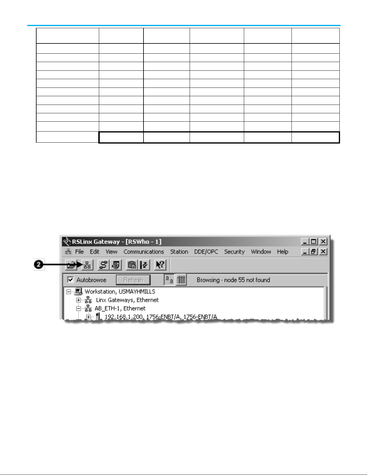
1. Start RSLinx communication software.
2. Click the Online button.
3. Expand a driver that lets you access the DeviceNet network.
4. Select the DeviceNet network.
52 Rockwell Automation Publication DNET-UM004D-EN-P - September 2020
Page 53

IMPORTANT
Create a New File for the
5. Make sure you see all the devices that are connected to the
DeviceNet network.
Chapter 5 Configure the Network Online
If you cannot view the network, verify that your computer is connected to the
network. Refer to Chapter 2 on page 25 for more information on how to connect the
computer to the network.
If you can view the network but cannot see all the devices that should be on the
network, verify the devices are connected to the network. Refer to Chapter 3 on page
29 for more information on how to connect the devices to the network.
Network
Rockwell Automation Publication DNET-UM004D-EN-P - September 2020 53
Before you go online, you must create a new network configuration file.
Complete the following steps to create a DeviceNet configuration file.
1. Start RSNetWorx for DeviceNet software.
2. Create a file.
Page 54

Chapter 5 Configure the Network Online
Go Online to Your Network
When you go online, RSNetWorx for DeviceNet software browses the
network once and shows the devices currently on the network in the new
network configuration file.
Keep in mind the following when you go online:
• RSNetWorx for DeviceNet software does not read (upload) or change
(download) the parameters of any of the devices on the network.
• The picture that results from browsing remains static. It does not show
any changes since the last browse.
Complete the following steps to go online.
1. Click the Online button.
2. Select the DeviceNet network.
54 Rockwell Automation Publication DNET-UM004D-EN-P - September 2020
Page 55

3. Click OK.
Chapter 5 Configure the Network Online
4. When the pop-up message appears, click OK.
5. Verify that you are online.
Rockwell Automation Publication DNET-UM004D-EN-P - September 2020 55
Page 56

Chapter 5 Configure the Network Online
Configure Each Device
Upload the Configuration of
Change and Download
Once the devices on the DeviceNet network appear in the network
configuration file, complete these tasks to change the configuration for
a device:
a Device
• Upload the Configuration of a Device on page 56
• Change and Download Device Configuration on page 56
When you configure the network online, the devices on the network have
parameters configured. Complete the following steps to upload configuration
from a device to the network configuration file.
1. Double-click the device to open the configuration dialog box.
2. Click the Parameters tab.
Device Configuration
3. When prompted, upload the configuration from the device to the
network configuration file.
After you upload a device’s configuration to the network configuration file,
you can make changes to the configuration and download it.
Complete the following steps to change and download new configuration
parameters.
56 Rockwell Automation Publication DNET-UM004D-EN-P - September 2020
Page 57

Chapter 5 Configure the Network Online
1. Double-click the device to open the configuration dialog box, or, if the
device configuration has already been uploaded and the configuration
dialog box is open, go to step 2.
The configuration dialog box appears.
2. Click the appropriate tab.
3. Set a parameter to the desired new value.
Typically, there are two methods to change a parameter:
• Choose a parameter from a pull-down menu
• Type a new value
4. Apply the changes.
5. Click OK to close the dialog box.
6. When prompted, download the changes.
Configure the Scanner
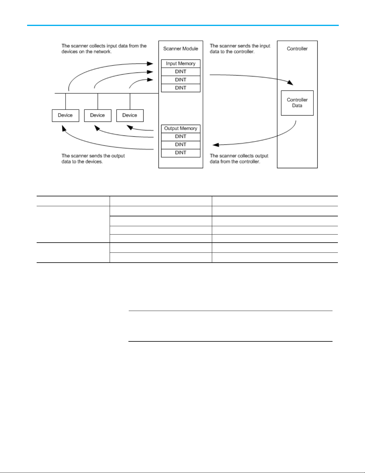
A DeviceNet scanner manages input and output data for a controller. The
scanner receives input data from I/O devices, organizes the information into
scanner data tables, and sends the input data to the controller when the
Rockwell Automation Publication DNET-UM004D-EN-P - September 2020 57
Page 58

Chapter 5 Configure the Network Online
Upload the Current Scanner
controller requests it. In addition, when the scanner receives output data from
the controller, it sends the data to the I/O devices.
A DeviceNet scanner is the only device that can be used as a master on a
DeviceNet network. When there is only one scanner on a network, it is the
master for that network by default. When there are multiple scanners on the
same network, each device can have only one scanner designated as its
master, which is the scanner that controls its outputs.
You must configure the scanner to define how it communicates with other
devices on the DeviceNet network. When you are configuring the network
online, complete the following tasks to configure the scanner:
• Upload the Current Scanner Configuration on page 58
• Define the Scanner Properties on page 59
• Build the Scan List on page 40
• Set the Alignment Option on page 42
Configuration
58 Rockwell Automation Publication DNET-UM004D-EN-P - September 2020
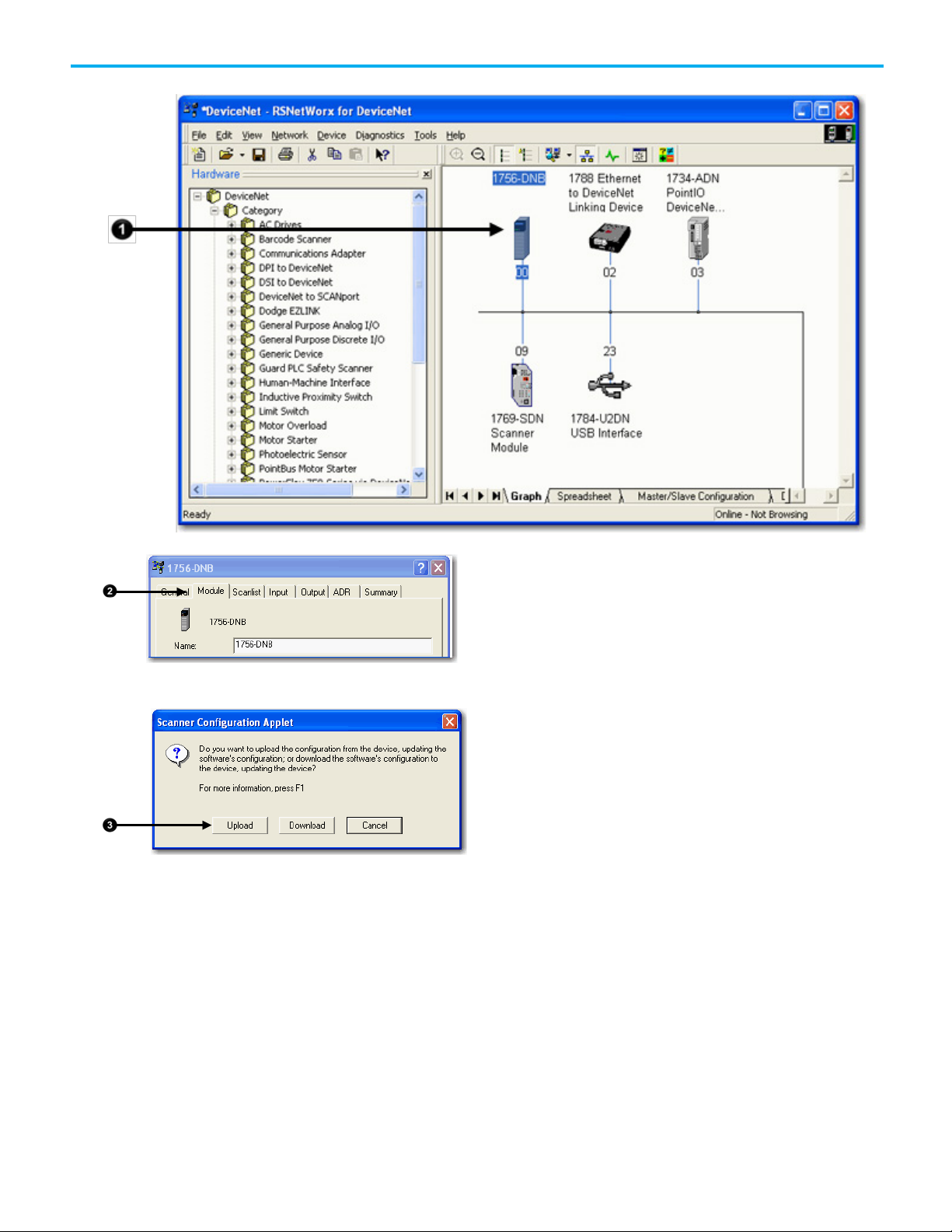
Complete the following steps to upload the current scanner configuration.
1. Double-click the scanner to open the configuration dialog box.
2. Click the Module tab.
3. When prompted, upload the configuration from the scanner.
Page 59
Define the Scanner
Chapter 5 Configure the Network Online
Properties
Complete the following steps to change the scanner properties, if necessary.
1. Click the Module tab.
2. Make the necessary changes.
3. Click Apply to make the changes.
4. When a message prompts you to indicate whether to download your
changes to the scanner, click No to continue configuring the scanner
on additional tabs.
Rockwell Automation Publication DNET-UM004D-EN-P - September 2020 59
Page 60

Chapter 5 Configure the Network Online
Build the Scan List
A scan list is a list of devices with which the scanner communicates. For each
device in the scanner’s scan list, the scanner sets aside input or output
memory for the data of the device.
60 Rockwell Automation Publication DNET-UM004D-EN-P - September 2020
Complete the following steps to build a scan list.
1. Double-click the scanner to open the configuration dialog box, or, if
the scanner configuration has already been uploaded and the
configuration dialog box is open, go to step 2.
2. Click the Scanlist tab. The devices on the network appear in the
Available Devices column.
Page 61

3. Clear or check Automap on Add.
RSNetWorx for DeviceNet software can automatically assign the
memory location for each device.
Chapter 5 Configure the Network Online
• If you want to leave gaps between devices in the memory, as shown
below, clear the box.
Leave Gaps Between Devices
• If you want to place devices in sequential DINT’s, as shown below,
leave the box checked. When you check the box, the software
automatically assigns a memory location for each device as you add
it to the scan list.
Place Devices in Sequential DINTs
Rockwell Automation Publication DNET-UM004D-EN-P - September 2020 61
Page 62

Chapter 5 Configure the Network Online
IMPORTANT
Move devices from the Available Devices column to the Scanlist
column.
If you get the following warning for a device, see
Set the I/O
Parameters of a Device on page 143 on page 167 on page 143.
Set the Alignment Option
Use the alignment option to map the I/O data so that it is aligned on a
boundary, such as a byte, word, or double-word, or efficiently grouped
without alignment in the input or output memory map. To map I/O data so it
is grouped without alignment, click the Pack Align option.
The alignment option you choose applies to both the input and output maps.
Complete these steps to select an alignment option.
1. Click the Input tab.
2. Click Options.
3. Click the desired data alignment.
62 Rockwell Automation Publication DNET-UM004D-EN-P - September 2020
Page 63
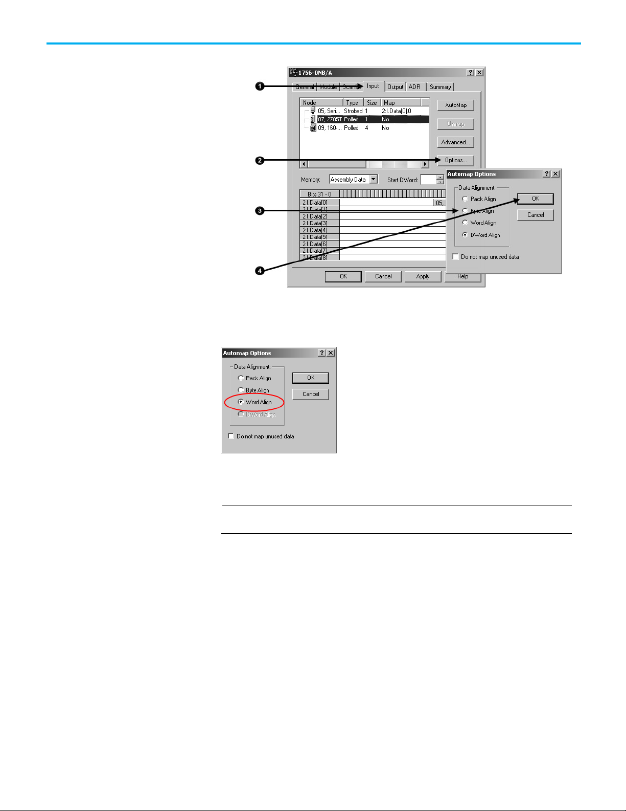
IMPORTANT
SoftLogix 5800 Controller
Manually Assign Each
Chapter 5 Configure the Network Online
4. Click OK.
In SoftLogix 5800 applications, the 1784-PCIDS scanner organizes its input
and output memory in 16-bit words. For that scanner, click Word Align.
Device to a Memory
Location
You can manually assign locations for device data.
If you configured the software to automatically assign memory locations as devices
are added, as described on page 70, skip this section.
Complete the following steps to manually assign each device to a memory
location.
1. Click the Input tab.
Rockwell Automation Publication DNET-UM004D-EN-P - September 2020 63
Page 64
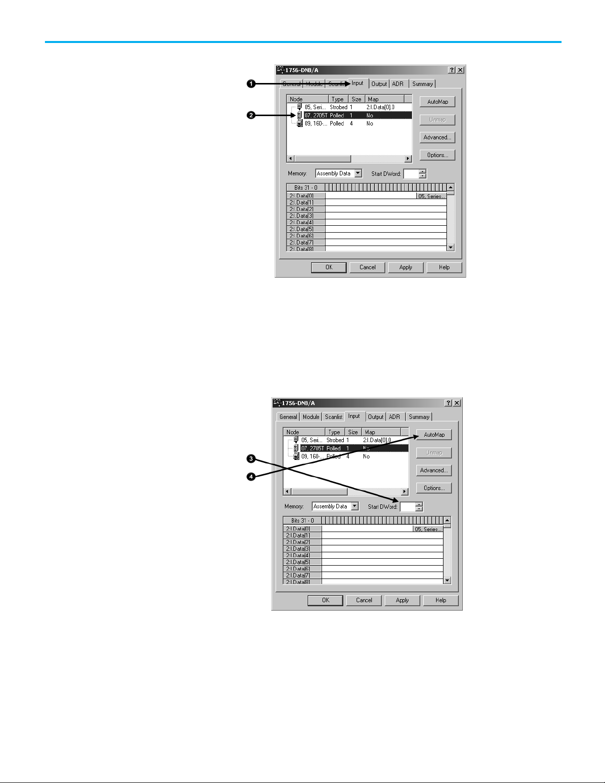
Chapter 5 Configure the Network Online
2. Select the device.
3. In the Start DWord field, enter the element number to which you want
to assign the data.
This is the starting point for the data. Larger data sizes wrap to several
elements. For example, to start the data in . . . Data[3], type 3 in the
Start DWord box.
4. Click Automap.
An entry for the device shows up in the input array.
5. Click the Output tab and repeat step through step .
6. Click OK to complete scanner configuration.
64 Rockwell Automation Publication DNET-UM004D-EN-P - September 2020
Page 65

Download the Configuration
Upload and Save the
Chapter 5 Configure the Network Online
Sometimes, a specific input or output value may end up as the upper bytes of a
DINT in the scanner.
To make your programming easier, use advanced mapping to re-map the
value to its own memory location. For more information, see
Map the Memory
Location with Advanced Mapping on page 153 on page 183 on page 153.
Complete these steps to download the configuration to the scanner.
to the Scanner
1. Click Apply.
2. When prompted, click Yes to download the changes.
3. Click OK.
Complete these steps to upload and save the configuration file.
Configuration File
Rockwell Automation Publication DNET-UM004D-EN-P - September 2020 65
1. Choose Network>Upload from Network.
2. When prompted, click Yes to upload the entire network.
3. Save the file.
Page 66
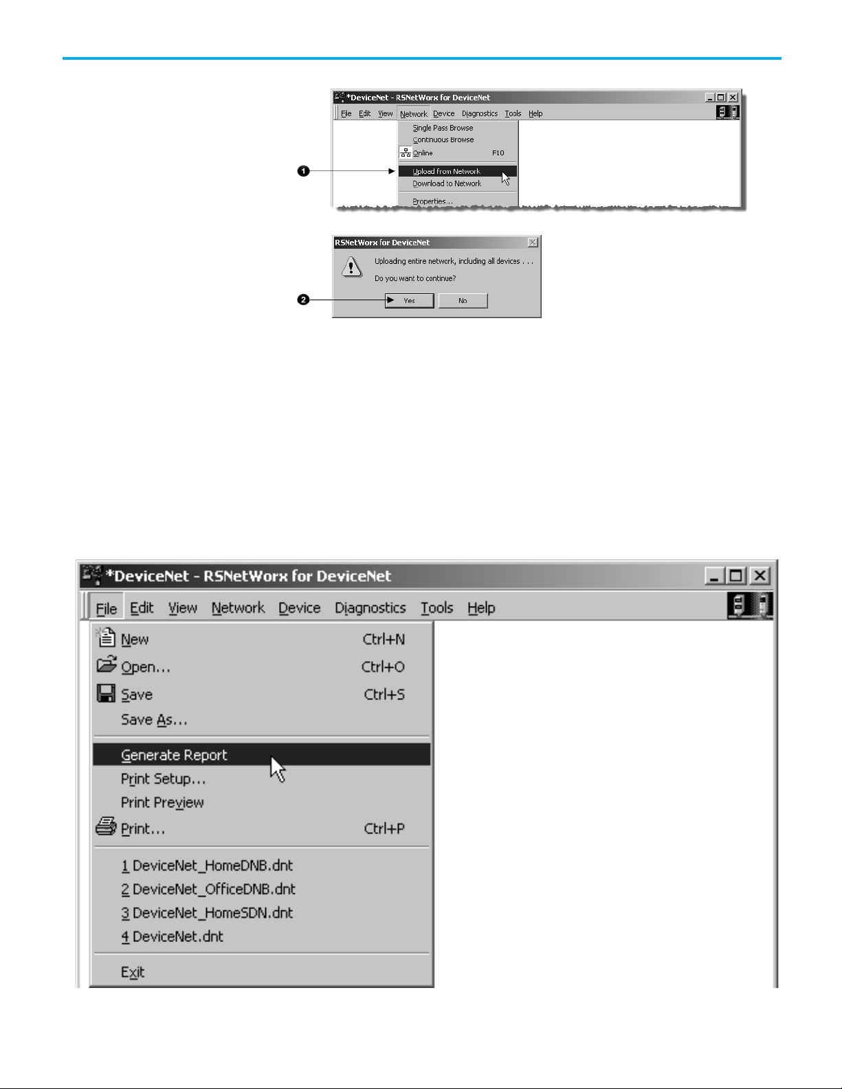
Chapter 5 Configure the Network Online
Generate an RSNetWorx for
An RSNetWorx for DeviceNet software report shows these items:
DeviceNet Report
• Devices on the network
• Memory addresses of devices in the scanner
• Device configurations
The report is a useful reference when you program your system. Complete the
following steps to generate a report.
1. From the File menu in RSNetWorx for DeviceNet software, choose
Generate Report.
66 Rockwell Automation Publication DNET-UM004D-EN-P - September 2020
Page 67

Chapter 5 Configure the Network Online
2. Click Generate report for entire network and click OK.
The report appears in your web browser.
Rockwell Automation Publication DNET-UM004D-EN-P - September 2020 67
Page 68

Page 69

Topic
Page
Determine If You Can Use AutoScan on page 71
82 on page 71
How AutoScan Affects Your Network on page 72
83 on page 72
Enable AutoScan with RSLogix 5000 Software on page 77
91 on page 77
Access Device Data on page 83
99 on page 83
Put the Scanner in Run Mode on page 84
100 on page 84
Additional Information About AutoScan on page 85
101 on page 85
IMPORTANT
How AutoScan Operates
Chapter 6
Automatically Configure a DeviceNet Network
This chapter provides a quick method for configuring a DeviceNet network. It
uses the AutoScan feature to establish communication between the controller
and the devices on the DeviceNet network with minimal steps.
How AutoScan Operates on page 69 80 on page 69
Install the DeviceNet Node Commissioning Tool on page 73 84 on page 73
Connect Devices to the Network on page 73 84 on page 73
Add the Scanner to the RSLogix 5000 Project on page 75 89 on page 75
The DeviceNet AutoScan feature enables a scanner to automatically map a
network of slave devices into its scan list without the use of RSNetWorx for
DeviceNet software. This greatly improves the ease of setting up a DeviceNet
network, especially networks comprised of simple devices.
When the feature is enabled, a DeviceNet scanner continuously searches for
devices on the network. Once a qualifying slave device is found, it is added to
the scanner's scan list and its I/O data is mapped into a predefined location in
the scanner's I/O memory table based on the device's node address.
AutoScan works only with 1756-DNB and 1769-SDN modules in Logix controller
applications.
AutoScan is active when the feature is enabled and the scanner is in Idle
mode. When active, the scanner attempts to connect to each device not
enabled in the scan list. The scanner only checks for devices with node
addresses between 0 and 61, inclusive. The connections to these devices are
made on a round-robin basis.
Rockwell Automation Publication DNET-UM004D-EN-P - September 2020 69
Page 70

Chapter 6 Automatically Configure a DeviceNet Network
Example
When a device is found, the scanner gets the produced and consumed data
sizes from the slave device’s Connection Object instances.
• If the produced data size is greater than the configured I/O allocation
size, the device is added to the scan list with a produced size set equal
to the I/O allocation size.
When this happens, an I/O connection is made with the device, but an error
occurs and error code #77 appears on the 1769-SDN for the device’s node
number.
• If the consumed data size is greater than the configured I/O allocation
size, then the node is rejected and not entered into the scan list.
However, you can change the I/O allocation size, as described in Configure
I/O Allocation Size Via the User Program on page 80, to accommodate the
device with the largest produced and consumed data sizes in your scan list.
For qualifying nodes, the scanner enters the device into the scan list and
attempts to allocate an I/O connection using one of the following
communication format choices in this particular order:
• Change Of State (COS) EPR = 250ms
• Poll EPR = 75ms
• Strobe EPR = 75ms
• Cyclic EPR = 500ms
If a photoeye is connected on a network that only supported strobed connections,
the scanner executes the following tasks:
• The scanner recognizes that a device exists for which memory is available for
the node number with the configured allocation size on a network that is not
currently mapped.
• The scanner attempts to initiate both COS and polled connections first, but the
strobed connection is selected as that is the only connection that the photoeye
supported.
The input and output data is mapped into the scanner's I/O data table based
on the device's node address and the configured fixed mapping size. The
DINT-based formula that is used with the CompactLogix controller for
calculating the input or output data location is as follows:
Input (Output) Offset = [(Node Address) x (Allocation Size)] / 4
70 Rockwell Automation Publication DNET-UM004D-EN-P - September 2020
Page 71

Example
IMPORTANT
In this formula the Data Offset = 66 for Input Offset and 2 for Output Offset.
Determine If You Can Use
When using the default fixed mapping size of 4 bytes, the input data for the devices shown in the example below is allocated in the 1769SDN's input table as shown below. Notice node 1 is in the data map at DINT location 1, node 2 at DINT location 2, and so on.
Notice that, in this example, node 4 is unused. However, the I/O memory slot remains allocated for it.
Chapter 6 Automatically Configure a DeviceNet Network
AutoScan
If you are using a MicroLogix 1500 controller with a 1769-SDN scanner, you must use
the following WORD-based formula for calculating the input or output data location:
Input (Output) Offset = ([(Node Address) x (Allocation Size)] / 2) + Data Offset
The data offset value is used to account for scanners that have a fixed status
field at the start of the input or output data, such as the 1769-SDN scanner.
Make sure your network meets these requirements to use this chapter:
• You have completed all the tasks required to do the following:
• Connect a computer and devices to the network.
• Create a network configuration file.
• Go online.
• Download the configuration file to the network.
Refer to Chapter 2 through Chapter 5 to complete the tasks listed above.
• Your DeviceNet scanner must support the AutoScan feature. For more
information, refer to your firmware release notes.
• Your application uses RSLogix 5000 programming software, version 13
or later.
• The scanner’s I/O allocation size is configured to accommodate the
input and output data sizes of all devices on your DeviceNet network.
The default AutoScan setting allocates a 4-byte entry in both the input and
output memory maps in the scanner for each slave device detected on the
network. This default size is chosen to accommodate the default Logix native
data size of 32 bits, that is a DINT.
Rockwell Automation Publication DNET-UM004D-EN-P - September 2020 71
Page 72

Chapter 6 Automatically Configure a DeviceNet Network
Consideration
Description
How AutoScan Affects Your
If you use a device that sends more than 4 bytes of input or output data, such
as an E3 Solid State Overload Relay (catalog number 193-ECxx), you must
change the I/O allocation size.
As you use AutoScan, keep in mind the considerations described in the
following table.
Network
AutoScan clears the current
configuration.
AutoScan allocates a fixed memory
size for each device.
The bytes/node value defines how
much memory for each address.
With AutoScan, the scanner automatically sets up communication with the devices
on your DeviceNet network. When you turn on the AutoScan option, the scanner
removes any previous configuration that was done to the scanner.
At its default setting, AutoScan allocates 1 DINT of input memory and 1 DINT of
output memory for each device on the DeviceNet network.
The actual data for the device fills the
portion that it needs and the rest
remains unused.
AutoScan lets you specify how much input and output memory to give to each
address on your network.
For example, if you specify 2 DINTs (8
bytes) per address, the scanner sets
aside 2 DINTs for each address.
The actual data for the device fills the
portion that it needs and the rest
remains unused.
New devices are automatically
available.
The Automatic Device Recovery (ADR)
option is not available.
72 Rockwell Automation Publication DNET-UM004D-EN-P - September 2020
While the scanner is in Idle mode, AutoScan continues to establish
communication with devices that you connect to the network, as long as the
devices use input data and output data sizes that fit in the scanner’s I/O allocation
size.
You have to use RSNetWorx for DeviceNet software to edit the configuration of
the scanner to use the Automatic Device Recovery (ADR) option of a DeviceNet
scanner. This turns off AutoScan.
Page 73

Give this address
To this device
Install the DeviceNet Node
Commissioning Tool
Connect Devices
Chapter 6 Automatically Configure a DeviceNet Network
Use the DeviceNet node commissioning tool to set a device’s node address
and baud rate when that device does not have a hardware mechanism to do
so.
You can skip this step if either of the following conditions apply:
• All your devices have hardware mechanisms to set a node address and
baud rate. In this case, you do not need the tool.
• You already have the tool installed.
Follow these steps to install the node commissioning tool.
1. On the RSLogix 5000 software CD, find the following folder where
language is the language of your software:
language\Tools\Node Commissioning Tool
For example, for software in English, open the ENU folder.
2. Follow the instructions in the readmefirst file.
When you use the AutoScan functionality, you should do the following:
• Install and configure the scanner and any network interface devices on
the network first.
• Install other devices on the network once the scanner and network
interface devices are on the network.
Install a Scanner or Network Interface Devices
Complete the following steps to install a scanner or network interface device
on the DeviceNet network.
1. Connect the scanner and any network interface devices to the network.
2. Set a node address for the scanner and any network interface devices.
Out of the box, a DeviceNet device is preset for node address 63. To avoid
address conflicts, connect and configure the devices one at a time. Otherwise,
the address conflicts may prevent communication.
The following addresses are recommended but not required.
0 Scanner.
1…61 Your devices.
62 Computer interface to the network, such as a 1784-U2DN or 1788-
PCIDS device.
63 Leave open. Out of the box, a DeviceNet communication module is
preset for address 63. Leaving address 63 open lets you get a new
device on the network without conflicting with another device.
Rockwell Automation Publication DNET-UM004D-EN-P - September 2020 73
• Refer to Set the Node Address of a Device on page 30 on page 27 for
more information on several options you can use to set the node
address.
Page 74

Chapter 6 Automatically Configure a DeviceNet Network
Give this address
To this device
1…61
Your devices
PCIDS device
Install Other DeviceNet
• Refer to Set the Node Address and Baud Rate with the DeviceNet
Node Commissioning Tool on page 87 on page 75 for more
information on how to use just the DeviceNet node commissioning
tool.
Set a baud rate for the scanner and any network interface devices.
When setting baud rates, consider the following:
• If you set the baud rate on the scanner or network interface device
before you install other devices on the network, you reduce the
number of baud rate errors.
• Scanners and network interface devices use a fixed baud rate.
• Sensors and similar DeviceNet communication modules use
autobaud to set their baud rate. They wait for another device to
communicate. Then they set their baud rate to the same baud rate as
the other device.
• By first placing a scanner or network interface device on the
network, the other device has a network baud rate against which to
set its baud rate.
• Initially, leave the baud rate of the scanner and network interface at
the default setting of 125KBps. If you want to change the baud rate,
wait until after you establish communication with all your devices at
the default setting (125K).
• Refer to Set the Node Address and Baud Rate with the DeviceNet
Node Commissioning Tool on page 87 on page 75 for more
information.
Devices
Complete the following steps to install other devices on the DeviceNet
network.
1. Connect the rest of your devices to the network one at a time.
2. Set a node address for each device after you add it to the network.
Out of the box, a DeviceNet device is preset for node address 63. To avoid
address conflicts, connect and configure the devices one at a time. Otherwise,
the address conflicts may prevent communication.
The following addresses are recommended but not required.
0 Scanner
62 Computer interface to the network, such as a 1784-U2DN or 1788-
63 Leave open. Out of the box, a DeviceNet communication module is
preset for address 63. Leaving address 63 open lets you get a new
device on the network without conflicting with another device.
74 Rockwell Automation Publication DNET-UM004D-EN-P - September 2020
Page 75

Set the Node Address and
Add the Scanner to the
Add the Scanner to the I/O
• Refer to Set the Node Address of a Device on page 30 on page 27 for
more information on how to use any of several options to set the
node address.
• Refer to Set the Node Address and Baud Rate with the DeviceNet
Node Commissioning Tool on page 87 on page 75 for more
information on how to use the DeviceNet node commissioning tool.
1. Set a baud rate for each device after you add it to the network.
When setting baud rates, consider the following:
• Sensors and similar DeviceNet communication modules use
autobaud to set their baud rate. They wait for another device to
communicate. Then they set their baud rate to the same baud rate as
the other device.
• If a device has a hardware mechanism to set its baud rate, set it to
autobaud, if available. Otherwise, set the device to the baud rate of
the network.
• After you change the address or baud rate of a device via a switch,
cycle power to the device.
• If a device has no hardware mechanism to set its address or baud
Refer to Set the Node Address and Baud Rate with the
rate,
DeviceNet Node Commissioning Tool on page 87 on page 75.
• After you set the address of a device, check its network status
indicator. Typically, a solid red indicator signifies an address
conflict or problem with the baud rate.
Chapter 6 Automatically Configure a DeviceNet Network
Baud Rate with the
DeviceNet Node
Commissioning Tool
RSLogix 5000 Project
Configuration Folder
Complete the following steps to set a node address and baud rate with the
DeviceNet node commissioning tool.
1. Start the node commissioning tool.
2. Click Browse.
3. Check I want to input the address for the device on the selected
network.
4. Select the DeviceNet network.
5. Enter the current address for the device. Out of the box, a device uses
address 63.
6. Click OK.
7. Enter the new address for the device.
8. Choose the baud rate for the device.
9. Click Apply.
To access the data of the network, add the scanner to the I/O configuration of
the controller.
Complete the following steps to add the scanner to the I/O configuration file.
1. Right-click and choose New Module.
2. Select the type of scanner.
Rockwell Automation Publication DNET-UM004D-EN-P - September 2020 75
Page 76

Chapter 6 Automatically Configure a DeviceNet Network
Define the Properties of the
3. Click OK.
4. From the Major Revision pull-down menu, choose a major revision
number for the scanner.
5. Click OK.
Scanner
Type a name for the scanner.
1. Enter the scanner node number.
2. Enter the scanner slot number.
3. Enter the scanner minor revision.
4. Enter the size of the input and output memory maps that the scanner
will allocate for each device it detects on the network.
Valid values range from 0…32 bytes per node.
5. If you need to make additional configuration changes, such as setting
the Requested Packet Interval (RPI), check Open Module Properties.
6. Click OK.
76 Rockwell Automation Publication DNET-UM004D-EN-P - September 2020
Page 77

IMPORTANT
data.
Enable AutoScan with
Chapter 6 Automatically Configure a DeviceNet Network
7. If the Module Properties dialog box appears, make any additional
configuration changes.
RSLogix 5000 Software
To enable AutoScan with RSLogix 5000 software, follow these steps.
1. Save changes to your RSLogix 5000 project.
2. Download the project to the Logix5000 controller.
In the following steps, you clear any existing configuration from the scanner
and reconfigure it to communicate with the devices on the network. In the
controller, this may change the tag addresses of the devices. If you have
already programmed your logic, make sure that it still addresses the correct
3. Double-click the scanner in the Controller Organizer to access
its properties.
4. Click the Scan List tab. A blue dot in the Nodes in Scan List section
indicates a device that the scanner now controls.
5. Check Enable AutoScan.
6. When the Enable AutoScan warning appears, click OK.
Rockwell Automation Publication DNET-UM004D-EN-P - September 2020 77
Page 78

Chapter 6 Automatically Configure a DeviceNet Network
Implementing AutoScan
Initiate AutoScan via the User Program
To enable AutoScan by using the MSG instruction, use the parameters shown
below and make sure that the message is sent to the appropriate DeviceNet
scanner. The figure shown below is from RSLogix 5000 software. Refer to the
appropriate user manuals to determine how to perform explicit messaging in
other PLC platforms.
This data tag should be configured as a SINT. Upon
execution of the MSG, AutoScan is:
Enabled if tag = 1
Disabled if tag = 0
78 Rockwell Automation Publication DNET-UM004D-EN-P - September 2020
To implement this feature, make sure that the appropriate version of
DeviceNet scanner is used. See page 97 on page 82
for the list of compatible
products supporting this feature.
This section describes how to set up the feature and how it operates. Notice
that explicit messaging is used for some of the steps. An explicit message can
be sent on a DeviceNet network in the following ways:
• A user ladder program
• External programming/configuration devices, such as the hand-held
DeviceNet Configuration Terminal, catalog number 193-DNCT
• RSNetWorx for DeviceNet software
Page 79

TIP
Chapter 6 Automatically Configure a DeviceNet Network
Since the purpose of the feature is to eliminate the use of RSNetWorx for
DeviceNet software, instructions on how to send an explicit message via the
class instance editor in the software are not covered in this document.
To implement the feature, follow these steps.
1. Set up the physical network.
Make sure all devices are addressed appropriately. For example, be sure there
are no address conflicts and devices are communicating at the same baud
rate.
The diagram below shows an example system using the 1756-DNB scanner.
You can commission the node addresses via hardware switches on the devices
or through other DeviceNet configurators, such as the hand-held DeviceNet
Configuration Terminal. For more information on how to set up the
DeviceNet Configuration Terminal’s node address, see the DeviceNet
Configuration Terminal User Manual, publication 193-UM009A-EN-P
.
1. Set up I/O allocation size in the scanner.
This step is optional.
The default AutoScan setting allocates a 4-byte entry in both the input and
output memory maps in the scanner for each slave device detected on the
network. This default size is chosen to accommodate the default Logix native
data size of 32 bits (DINT). If that is adequate for the application, go to step 3.
For applications where you want to customize the I/O allocation size, the 4byte allocation can be adjusted through an explicit message to the scanner
Rockwell Automation Publication DNET-UM004D-EN-P - September 2020 79
Page 80

Chapter 6 Automatically Configure a DeviceNet Network
Field
Value
Class
90 Hex
Instance
1
Attribute
11 Hex
Configure I/O Allocation
Configure I/O Allocation Via
using the SetAttributeSingle service. The entry allocation can be configured
for 1 to 32 bytes per node.
Configure the allocation size using one of these methods:
Size Via the User Program
• Configure I/O Allocation Size Via the User Program on page 80
• Configure I/O Allocation Via a DeviceView Configurator on page 80
Use the parameters shown in the Message Configuration dialog box below to
adjust the I/O allocation size. Make sure that the message is sent to the
appropriate DeviceNet scanner.
This data tag should be configured as an SINT, and should contain
the value of the desired per-node fixed mapping size (1 - 32).
a DeviceView Configurator
Rockwell Automation offers the hand-held DeviceNet Configuration
Terminal, catalog number 193-DNCT, to configure individual devices on a
DeviceNet network.
To configure the I/O allocation size, attach a configurator device on the
network and send an explicit message to the scanner by using the parameters
below. Send the desired allocation size (1…32 bytes) to the attribute below to
configure the per-node I/O allocation.
Service Code 10 Hex
For more information on how to use the DeviceNet Configuration Terminal,
refer to these publications:
• 193-DNCT DeviceNet Configuration Terminal Quick Reference,
publication 193-QR002A-EN-P
• DeviceNet Programming Terminal User Manual, publication 193-
UM009A-EN-P
80 Rockwell Automation Publication DNET-UM004D-EN-P - September 2020
Page 81
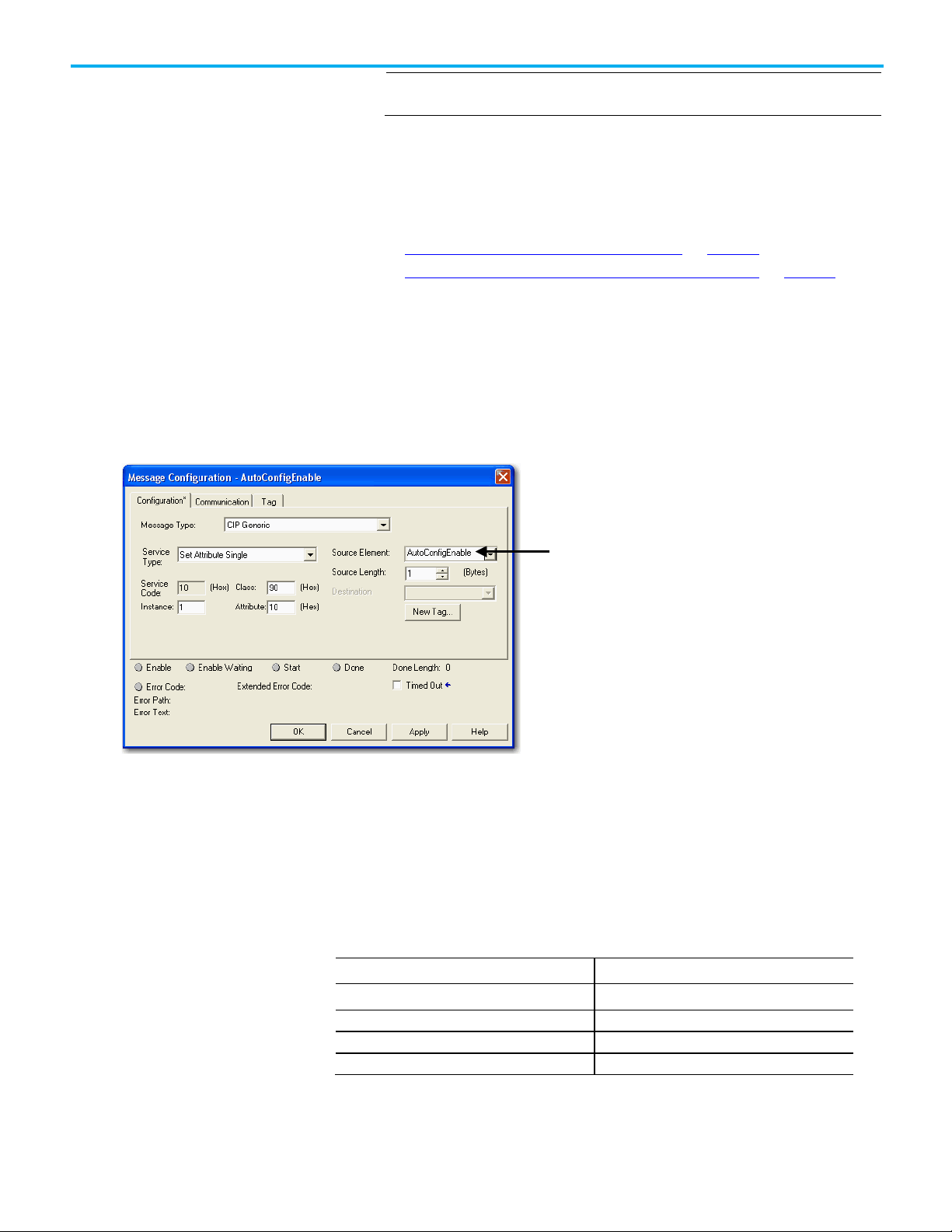
IMPORTANT
Field
Value
Attribute
11 Hex
Initiate AutoScan via the
Initiate AutoScan via the
Chapter 6 Automatically Configure a DeviceNet Network
You can change the I/O allocation size only when the scanner is in Idle mode,
and the AutoScan feature is disabled.
1. Enable AutoScan.
This is accomplished by executing an explicit message to the scanner by using
the SetAttributeSingle service. As mentioned before, there are multiple ways
to send an explicit message on DeviceNet, including the following:
User Program
• Initiate AutoScan Via the User Program on page 78
• Initiate AutoScan via the DeviceView Configurator on page 81
To enable AutoScan by using the MSG instruction, use the parameters shown
below and make sure that the message is sent to the appropriate DeviceNet
scanner. The figure shown below is from RSLogix 5000 software. Refer to the
appropriate user manuals to determine how to perform explicit messaging in
other PLC platforms.
This data tag should be configured as a SINT. Upon execution of
the MSG, AutoScan is:
Enabled if tag = 1
Disabled if tag = 0
DeviceView Configurator
Rockwell Automation Publication DNET-UM004D-EN-P - September 2020 81
To enable AutoScan by using a DeviceNet configurator, attach the device on
the network and send an explicit message to the scanner using the
parameters below. Send a 1 to that attribute to enable the feature, and 0 to
disable.
Service Code 10 Hex
Class 90 Hex
Instance 1
For more information on how to use the DeviceNet Configuration Terminal,
refer to these publications:
Page 82

Chapter 6 Automatically Configure a DeviceNet Network
IMPORTANT
Example
Safety
Status Code (Decimal)
Description of Status
Additional Considerations
• 193-DNCT DeviceNet Configuration Terminal Quick Reference,
publication 193-QR002A-EN-P
• DeviceNet Programming Terminal User Manual, publication 193-
UM009A-EN-P.
Once the feature is enabled, the scanner scans the network to populate and
configure the scan list automatically.
1. Put scanner in RUN mode to begin system operation.
The factory default setting for AutoScan is disabled for all products.
You can change the I/O allocation size only when the scanner is in Idle mode,
and the AutoScan feature is disabled.
Regarding AutoScan
Make sure that input or output data memory size in the scanner is large
enough to accommodate the size required based on the number of nodes on
the network and the AutoScan I/O allocation size per node.
If the I/O allocation size per node is configured for 16 bytes and there are 32 slave
devices on the network (node addresses 1…32), AutoScan requires 16 bytes x 32 = 512
bytes (128 DINT) of I/O space in both the scanner's input and output table. Assuming it
is a ControlLogix system, the maximum scanner input data table size is 124 DINT and
123 DINT for output. The required space exceeds what the 1756-DNB can support. You
would need to adjust the I/O allocation size or reduce the slave device count on the
network to include all of the devices in the scan list.
ATTENTION: Devices outside of the scanner's allowable I/O image space will be rejected
and will not be included in the scan list.
The AutoScan feature is automatically disabled in the scanner as soon as a
scanner property is modified by RSNetWorx for DeviceNet software. For
example, any manual changes to the scan list using RSNetWorx for DeviceNet
software disables the AutoScan feature in the scanner.
82 Rockwell Automation Publication DNET-UM004D-EN-P - September 2020
One new status code has been added to the Node Status list. This code is
presented in the Node Status Table.
65 AutoScan Active (Scanner only status)
When the scanner is in Run mode with AutoScan enabled, the scanner display
alternates between 65 and the scanner node address.
Page 83
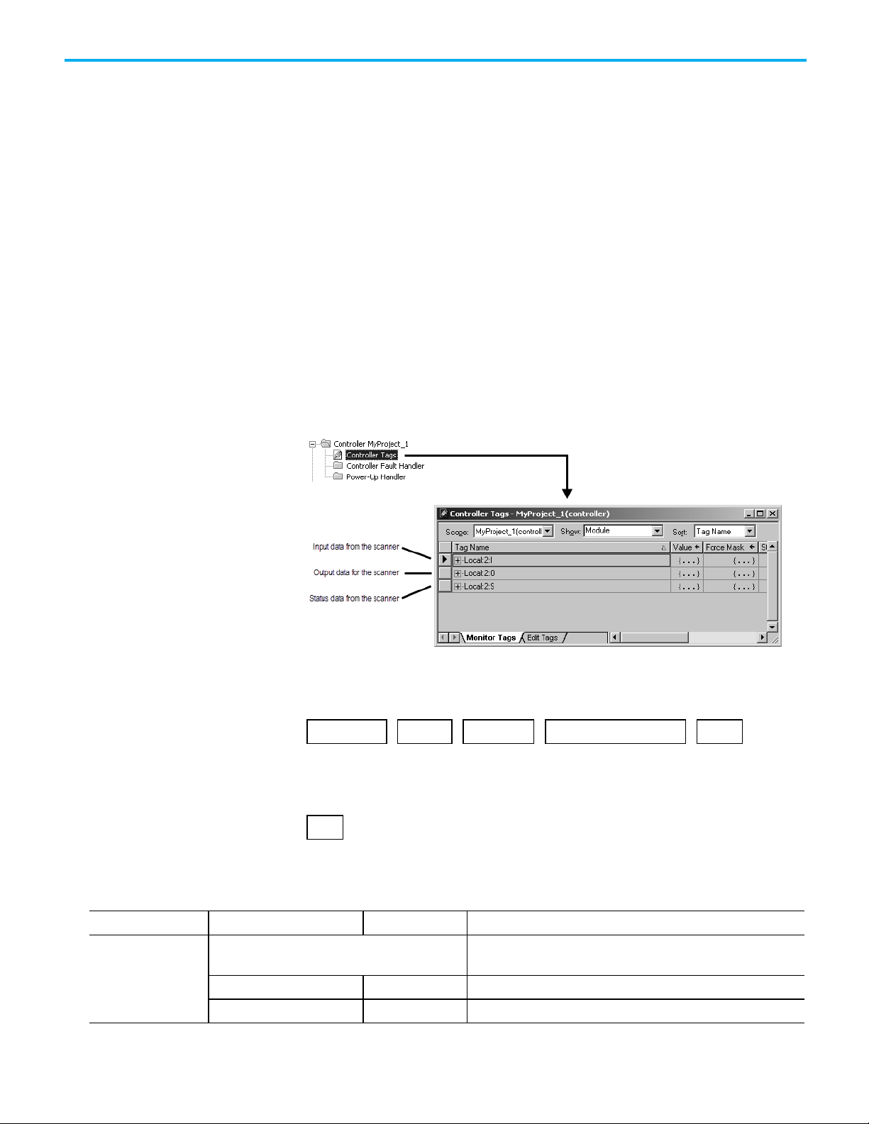
Where
Is
If you have this scanner
In a
Then location is
Access Device Data
When a scanner is transitioned from Run mode to Idle mode while AutoScan
is enabled, it only scans the network for nodes that are not already in the scan
list. However, while in Idle mode, an AutoScan DISABLE to ENABLE
transition causes the scanner to erase the existing scan list and scan for all
nodes on the network.
The AutoScan feature enables AAR (Auto-Address Recovery) for each of the
configured slave devices.
The AutoScan feature checks for the Quick Connect setting in each slave
device and enables Quick Connect in the scanner if it is enabled in the slave
devices.
When you add the scanner to the I/O configuration of the controller,
RSLogix 5000 software automatically creates a set of tags for the input,
output, and status data of the network.
Chapter 6 Automatically Configure a DeviceNet Network
location
The tags for your DeviceNet data follow this format.
location
:type
.Data
[dnet_address]
= Optional
location of the scanner in the system
ControlLogix 1756-DNB local chassis Local:slot_number_of_scanner
.bit
Rockwell Automation Publication DNET-UM004D-EN-P - September 2020 83
Page 84

Chapter 6 Automatically Configure a DeviceNet Network
Where
Is
chassis.
Where
Is
input from a device
I output to a device
O
If you want to
Then set this bit
To
Not fault the network
…O.CommandRegister.Fault
0
Disable the network
…O.CommandRegister.DisableNetwork
1
Enable the network
…O.CommandRegister.DisableNetwork
0
Halt the scanner (ceases all operation)
…O.CommandRegister.HaltScanner
1
Unhalt the scanner
…O.CommandRegister.HaltScanner
0
Reset the scanner
…O.CommandRegister.Reset
1
If you have this scanner
Then this indicator
Displays
CompactLogix 1769-SDN
2-character display
its node number when in Run mode
Put the Scanner in Run
remote chassis adapter:slot_number_of_scanner
where:
adapter is the name of the EtherNet/IP or ControlNet module in the remote
type
dnet_address
bit
Mode
type of data:
address of the device on the DeviceNet network (based on only 4 bytes per node)
specific bit within the data of the
device
While you can use the input and output tags of the scanner directly in your
logic, it is a lot easier to use alias tags. Alias tags can be used whether you use
AutoScan or not to configure the scanner.
To run the DeviceNet network, follow these steps.
1. Place the controller in Run or Remote Run mode.
Tip: To put the scanner in Run mode, set the …O.CommandRegister.Run bit to 1.
2. Set the following bit of the output structure for the scanner.
Run the network …O.CommandRegister.Run 1
Not run the network (Idle mode) …O.CommandRegister.Run 0
Fault the network …O.CommandRegister.Fault 1
Resume operation after a reset …O.CommandRegister.Reset 0
3. Check the scanner for Run mode.
ControlLogix 1756-DNB 4-character display RUN
84 Rockwell Automation Publication DNET-UM004D-EN-P - September 2020
Page 85

Consideration
Additional Information
About AutoScan
Allocating More Memory for
Chapter 6 Automatically Configure a DeviceNet Network
The type of update (connection) that the scanner sets up with each device
depends on the device. The scanner chooses the first connection type that the
device supports in this order:
Type of Connection that the Scanner Sets Up
Each Device
1. Change-of-state (COS)
2. Polled
3. Strobed
4. Cyclic at 1000 ms
The scanner tries to set up a change-of-state connection. If the device does not
support change-of-state, then the scanner tries to set up a polled connection
and so on. The type of connection that the scanner sets up may not be the
default for the device.
The AutoScan feature is easiest to use if you leave it set to 1 DINT (4 bytes) of
input memory and output memory for each address.
Number of bytes of
input memory and
output memory to
allocate in for each
address
The bytes/node value defines the amount of
memory for each address.
As an option, you can allocate more memory for each device.
Description
AutoScan lets you specify how much input and output memory to give to
each address on the network.
For example, if you specify 2
DINTs (8 bytes) per address, the
scanner sets aside 2 DINTs for
each address
The actual data for the device fills
the portion that it needs and the
rest remains unused.
Rockwell Automation Publication DNET-UM004D-EN-P - September 2020 85
Page 86

Chapter 6 Automatically Configure a DeviceNet Network
Consideration
Description
The scanner sets-up communication with any device
that fits within the allocated memory size.
The scanner automatically sets up communication with those devices that fit within the memory allocated
for each address.
• For example, if you allocate 2 DINTs (8 bytes) per address, the scanner sets up communication with any
device that sends or receives 1…8 bytes of data.
• The scanner adds as many device as it can until it runs out of memory.
If you give too much memory to each address, you may not have enough
memory for all your devices.
The scanner skips devices that are too large. If a device needs more memory than is allocated, the scanner skips it and does not set up communication
with it.
For example, if you specify 2 DINTs (8 bytes) per address but a device
sends 9 bytes, the scanner does not add the device to the scan list.
Manually editing the scan list turns off AutoScan. If you use RSNetWorx for DeviceNet software to edit the configuration of the scanner, the scanner turns off
AutoScan. Do not turn it back on or you will clear the configuration that you just entered.
For example, if you use RSNetWorx for DeviceNet software to manually
add a device to the scan list, the scanner turns off AutoScan. If turn on
AutoScan again, the scanner clears it current configuration and starts
over.
86 Rockwell Automation Publication DNET-UM004D-EN-P - September 2020
Page 87

Topic
Page
Determine the Address of DeviceNet Data on page 92
109 on page 92
Determine If a Device Has Failed on page 95
112 on page 95
Place the Scanner in Run Mode on page 96
113 on page 96
Test the Parameter on page 98
116 on page 98
Enter Message Logic on page 99
117 on page 99
Before You Begin
Chapter 7
Control a Device
Use this chapter to develop the logic that examines and controls your devices.
Before You Begin on page 27 104 on page 27
When to Use a MSG Instruction on page 96 113 on page 96
Determine the Parameter Number to Access on page 97 114 on page 97
Determine the Configuration of the Parameter on page 97 114 on page 97
Before you use this chapter, make sure that you can see all your devices on the
DeviceNet network. Complete the following steps to see your DeviceNet
network.
1. Start RSLinx communication software.
2. Browse the network.
3. Expand a driver that lets you access the DeviceNet network.
4. Select the DeviceNet network.
Rockwell Automation Publication DNET-UM004D-EN-P - September 2020 87
Page 88

Chapter 7 Control a Device
5. Verify that you see all the devices that are connected to the DeviceNet
network.
RSNetWorx Report for the Network
88 Rockwell Automation Publication DNET-UM004D-EN-P - September 2020
Page 89

Example
Data Map for Each of Your
Devices
Add the Scanner to the
Conserve EtherNet/IP or
Chapter 7 Control a Device
Controller’s I/O
Configuration
ControlNet Network
Bandwidth
To access the data of the network, add the scanner to the controller’s I/O
configuration in RSLogix 5000 programming software. However, you may
need to conserve bandwidth on the EtherNet/IP or ControlNet network.
The default configuration of the scanner gives you the maximum amount of
input, output, and status data, as shown in the following graphic.
If the scanner communicates with the controller via an EtherNet/IP or
ControlNet network and you need to conserve bandwidth over that network,
consider reducing the input, output, or status sizes.
• Set the input and output sizes = the number of input and output
DINTs in the scanner that actually store device data.
• If you are not going to use all the status information, set the status size
to the minimum required.
Rockwell Automation Publication DNET-UM004D-EN-P - September 2020 89
If you want to use only the ASCII representation of scanner status/display,
set the status size to 10.
If you also want to read the status code of the scanner, set the
status size to 11.
Page 90

Chapter 7 Control a Device
If you want the following information
Set the status size
Member
Data Type
• If a bit = 1, then the device at that address has failed.
If a bit = 1, then their is a mismatch with that address.
• If a bit = 1, then the device at that address is idle.
• If a bit = 1, then the device at that address is online.
ScrollingDeviceStatus member shows the status code
• ScrollingDeviceAddress member shows the address
Status code of all devices—1 byte per device
32
DeviceStatus
SINT[64]
Add the Scanner to the I/O
See Table 1 - Set the Status Size for a Scanner on page 106 for more
information on how to change the status size of a scanner from the default
values.
(DINTs) to the
following value
Count of I/O scans 10 ScanCounter DINT
Indication that a device has failed:
• There is 1 bit for each address on the DeviceNet network (0 - 63).
• The position of a bit = address of a device.
Indication that the data size of a device does not match the amount of memory
allocated for the device in the scanner:
• There is 1 bit for each address on the DeviceNet network (0 - 63).
• The position of a bit = address of a device.
•
Indication that a device is idle:
• There is 1 bit for each address on the DeviceNet network (0 - 63).
• The position of a bit = address of a device.
Indication that a device is online:
• There is 1 bit for each address on the DeviceNet network (0 - 63).
• The position of a bit = address of a device.
This setting gives you the
following parameter values.
DeviceFailureRegister SINT[8]
AutoverifyFailureRegister SINT[8]
DeviceIdleRegister SINT[8]
ActiveNodeRegister SINT[8]
ASCII representation of scanner status/display StatusDisplay SINT[4]
Address of the scanner 11 ScannerAddress SINT
Status code of scanner ScannerStatus SINT
Address with an error:
• Scrolls through the addresses with errors
•
Status code of an address with an error:
• Scrolls through addresses with errors
Possible future expansion of the structure—5 DINTs 16
Status code of lower 32 devices—1 byte per device 24 DeviceStatus SINT[32]
Configuration Folder
ScrollingDeviceAddress SINT
ScrollingDeviceStatus SINT
Complete the following steps to add the scanner to the I/O configuration file.
1. Right-click and choose New Module.
2. Select the type of scanner.
3. Click OK.
4. From the Major Revision pull-down menu, choose a major revision
number for the scanner.
90 Rockwell Automation Publication DNET-UM004D-EN-P - September 2020
Page 91
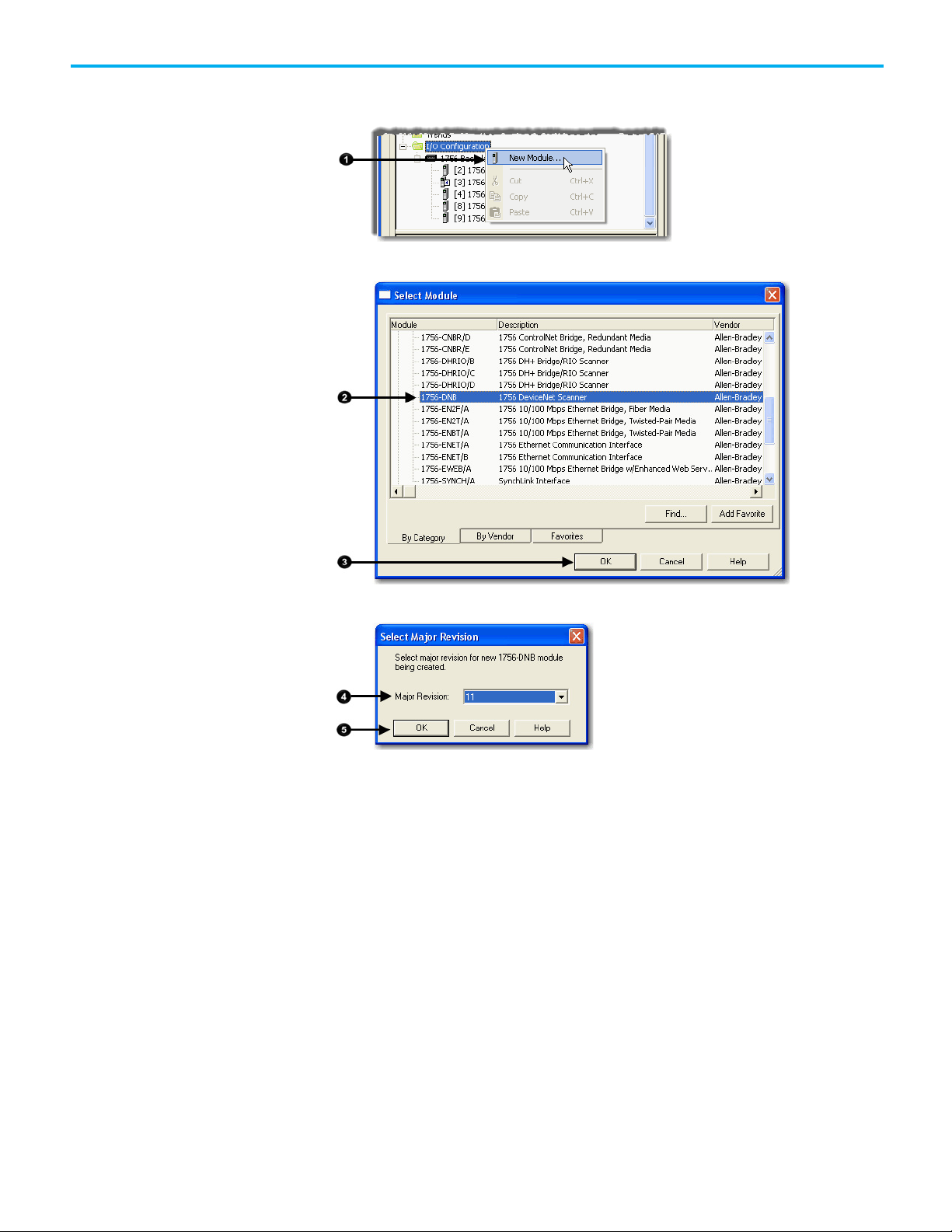
Configure the Scanner
5. Click OK.
Chapter 7 Control a Device
Complete the following steps to configure the scanner.
1. Type a name for the scanner.
2. Enter a node number.
3. Enter the slot number.
4. Enter the minor revision.
5. Enter the size of the input and output memory maps that the scanner
will allocate for each device it detects on the network.
Valid values range from 0…32 bytes per node.
6. If you need to make additional configuration changes, such as setting
the requested packet interval (RPI), check Open Module Properties.
Rockwell Automation Publication DNET-UM004D-EN-P - September 2020 91
Page 92

Chapter 7 Control a Device
Determine the Address of
7. Click OK.
8. If the Module Properties dialog box appears, make additional
configuration changes.
You can change scanner configuration on the following tabs:
• General
• Connection
• RSNetWorx
DeviceNet Data
When you add the scanner to the I/O configuration of the controller,
RSLogix 5000 programming software automatically creates a set of tags for
the input, output, and status data of the network.
The tags for your DeviceNet data follow this format.
92 Rockwell Automation Publication DNET-UM004D-EN-P - September 2020
Page 93

Where
Is
If you have this scanner
If the data is
Chapter 7 Control a Device
Slot
Location
The scanner memory uses this format...
slot
type
.Data
[element]
= Optional
The slot number of the scanner
Local ControlLogix 1756-DNB
Remote ControlLogix 1756-DNB
which is this tag in the controller.
.bit
location
:type
.Data
[element]
Then location is
Local:slot_number_of_scanner
name_of_remote_bridge:slot_number_of_scanner
.bit
Type
Element
Bit
CompactLogix 1769-SDN
SoftLogix 5800 1784-PCIDS
Linking Device 1788-EN2DN or 1788-CN2DN
Local:slot_number_of_scanner
Local:slot_number_of_scanner
The name of the linking device in the I/O configuration of the
controller
Then type is
Input from a device
Output to a device
The status of the network
I
O
S
A specific DINT (DWord, 32-bit integer) within the array
A specific bit within an integer
Rockwell Automation Publication DNET-UM004D-EN-P - September 2020 93
Complete the following steps to determine the tag name, or address, for
DeviceNet data.
Page 94
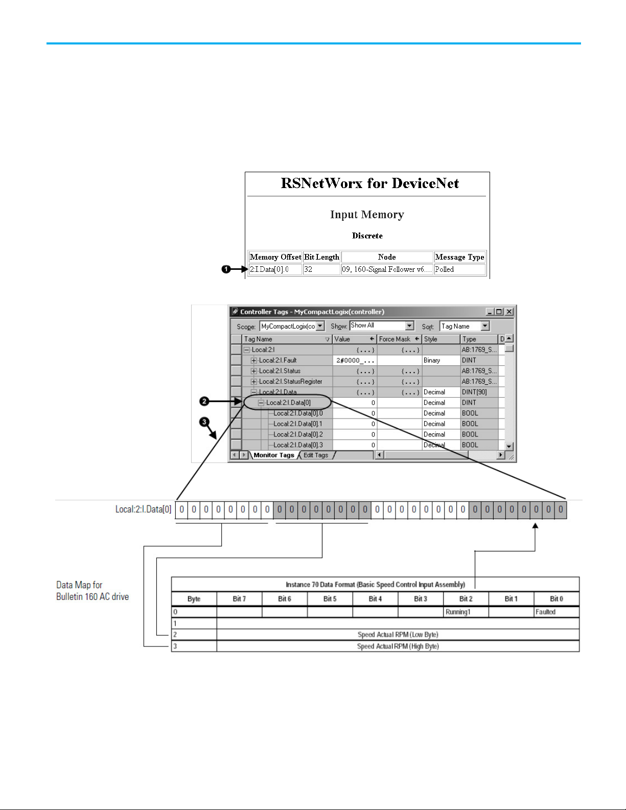
Chapter 7 Control a Device
SoftLogix 5800 Controller
1. On the RSNetWorx report for the network, find the memory address
for the input or output data of the device.
2. Find the corresponding tag in the controller-scoped tags of the
controller.
3. Find the required data within the controller tag.
Use the data map for the device as a reference.
94 Rockwell Automation Publication DNET-UM004D-EN-P - September 2020
The SoftLogix 5800 scanner 1784-PCIDS organizes input and output memory
in 16-bit words. It uses address format word.bit.
Page 95
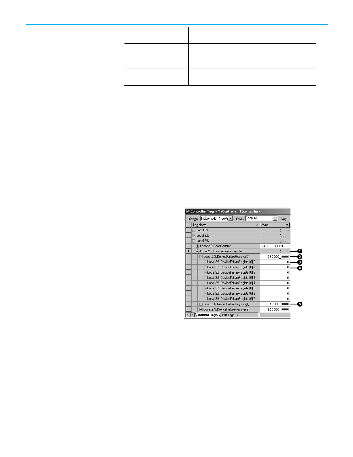
Where
4
Address 1
Determine If a Device Has
Is
Chapter 7 Control a Device
Failed
Word
Bit
While you can use the input and output tags of the scanner directly in your
logic, it is easier to use alias tags.
If a DeviceNet communication device stops communicating, such as because
of a device failure, the tag for the device stays at its last value. To make sure
that your input data is valid, we recommend that you buffer the input data
and examine the device failure register.
1 Indication that a device has failed.
There is 1 bit for each address on the DeviceNet network.
If a bit = 1, then the device at that address has failed.
INT (16-bit integer) with the memory of the
scanner
A specific bit within an integer
2 Addresses 0 to 7
3 Address 0
5 Addresses 8 to 15
On every scan of the controller, execute logic similar to the following:
If PhotoEye_RawData = 1 and PhotoEye_Failed = 0 then
PhoteEye = 1
Otherwise PhoteEye = 0
Use the PhotoEye tag in the rest of your logic (not PhotoEye_RawData).
Rockwell Automation Publication DNET-UM004D-EN-P - September 2020 95
Page 96

Chapter 7 Control a Device
If you want to
Set this bit
To
Not fault the network
…O.CommandRegister.Fault
0
Disable the network
…O.CommandRegister.DisableNetwork
1
Enable the network
…O.CommandRegister.DisableNetwork
0
Halt the scanner (ceases all operation)
…O.CommandRegister.HaltScanner
1
Unhalt the scanner
…O.CommandRegister.HaltScanner
0
Reset the scanner
…O.CommandRegister.Reset
1
Place the Scanner in Run
Mode
Complete the following steps to run the DeviceNet network.
Tip: To put the scanner in Run mode, set the …O.CommandRegister.Run bit to 1.
1. Set the following bit of the output structure for the scanner.
Run the network …O.CommandRegister.Run 1
Not run the network (idle mode) …O.CommandRegister.Run 0
Fault the network …O.CommandRegister.Fault 1
Resume operation after a reset …O.CommandRegister.Reset 0
2. Place the controller in Run or Remote Run mode.
When to Use an MSG Instruction
96 Rockwell Automation Publication DNET-UM004D-EN-P - September 2020
If you want to set or get a parameter based on conditions in your logic, use a
Message (MSG) instruction in ladder logic to access the parameter.
Page 97

Item
Value
Instance # (hex)
Attribute # (hex)
Determine the Parameter
Determine the
Chapter 7 Control a Device
Number to Access
Configuration of the
Parameter
Some parameters do not require ongoing updates. For example, initializing
configuration parameters may occur only when the controller goes to Run
mode. By using a MSG instruction for those parameters, you save bandwidth
on the DeviceNet network for more critical or ongoing data.
Use RSNetWorx for DeviceNet software to determine the parameter number
that you want to access. Some parameters are read-only and are shown with a
lock symbol.
Find the information about the parameters listed in the following table to get
or set a parameter.
Rockwell Automation Publication DNET-UM004D-EN-P - September 2020 97
Class # (hex)
Page 98
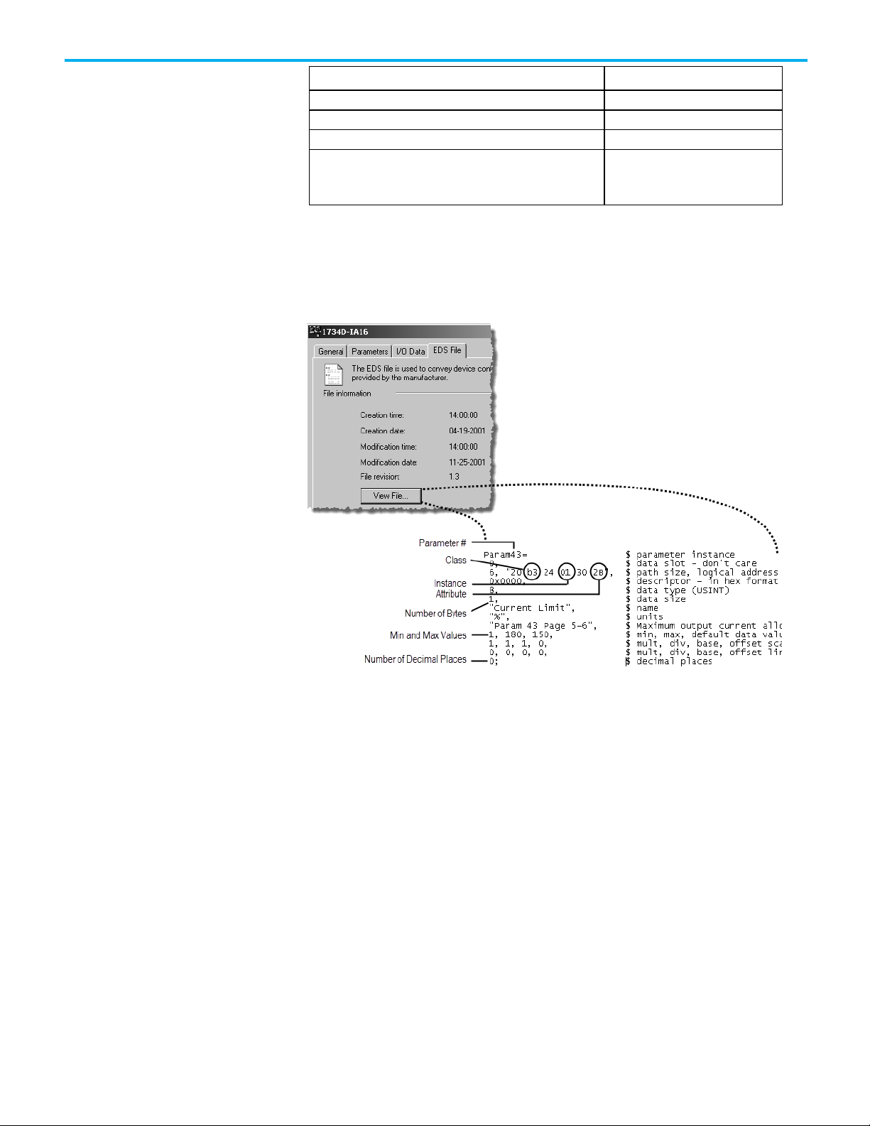
Chapter 7 Control a Device
Item
Value
Maximum value
Test the Parameter
Number of bytes (size)
Minimum value
Decimal places
Some devices assume a specific number of decimal places in a
value.
In addition to the documentation for the device, the EDS file may also give
you the required information.
98 Rockwell Automation Publication DNET-UM004D-EN-P - September 2020
A simple way to make sure that you have the correct configuration for a
parameter, such as data size or values, is to use the Class Instance editor in
RSNetWorx for DeviceNet software.
Complete the following steps to test the parameter.
1. In RSNetWorx for DeviceNet software, go online to the DeviceNet
network.
2. Right-click the device and choose Class Instance Editor.
3. Type the class, instance, and attribute for the parameter.
4. Change the parameter.
a. Choose Set Single Attribute.
b. Choose the number of bytes.
c. Type the new value in hexadecimal format.
Page 99

Enter Message Logic
Chapter 7 Control a Device
5. From the Description pull-down menu, choose Get Single Attribute to
read the parameter.
6. Click Execute.
7. To change how output data is displayed, choose the size and format.
Rockwell Automation Publication DNET-UM004D-EN-P - September 2020 99
To access the parameter of a device (get or set the parameter), configure the
MSG instruction as CIP Generic.
Page 100
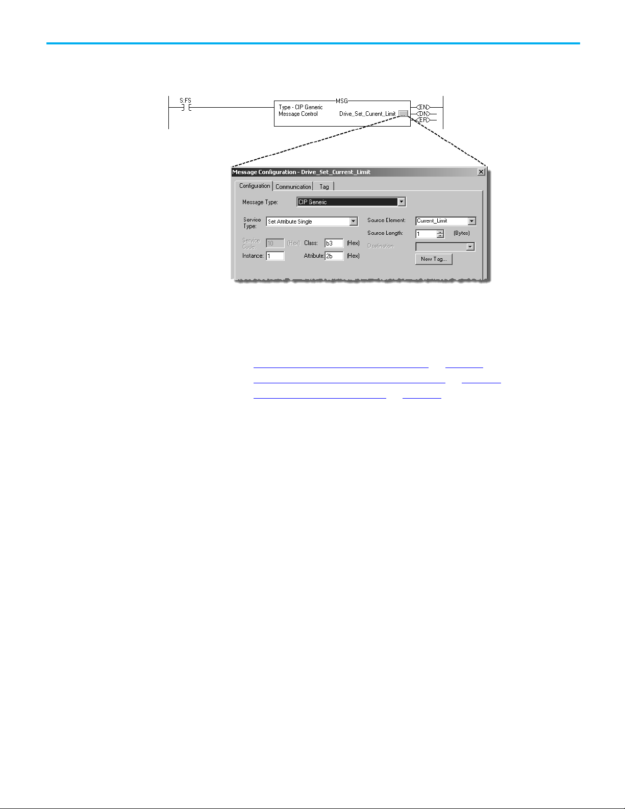
Chapter 7 Control a Device
Change the current limit of the drive.
You must complete the following tasks to configure the MSG instruction:
• Define the Source or Destination Data on page 101
• Enter and Configure the MSG Instruction on page 102
• Set the Communication Path on page 103
100 Rockwell Automation Publication DNET-UM004D-EN-P - September 2020
 Loading...