

Page 1

Quick Start Guide
Original Instructions
Studio 5000 Smart Object Configurator Quick Start Guide
1756 ControlLogix, 1756 GuardLogix, 1769 CompactLogix,
1769 Compact GuardLogix, 1789 SoftLogix, 5069
CompactLogix, 5069 Compact GuardLogix, Studio 5000
Logix Emulate
Page 2
Studio 5000 Smart Object Configurator Quick Start Guide
personal injury or death, property damage, or economic loss.
Attentions help you identify a hazard, avoid a hazard, and recognize the consequence.
IMPORTANT
SHOCK HAZARD: Labels may be on or inside the equipment, for example, a drive or motor, to alert people that dangerous voltage may be present.
temperatures.
for Personal Protective Equipment (PPE).
Important User Information
Read this document and the documents listed in the additional resources section about installation, configuration, and
operation of this equipment before you install, configure, operate, or maintain this product. Users are required to familiarize
themselves with installation and wiring instructions in addition to requirements of all applicable codes, laws, and standards.
Activities including installation, adjustments, putting into service, use, assembly, disassembly, and maintenance are required to
be carried out by suitably trained personnel in accordance with applicable code of practice.
If this equipment is used in a manner not specified by the manufacturer, the protection provided by the equipment may be
impaired.
In no event will Rockwell Automation, Inc. be responsible or liable for indirect or consequential damages resulting from the use
or application of this equipment.
The examples and diagrams in this manual are included solely for illustrative purposes. Because of the many variables and
requirements associated with any particular installation, Rockwell Automation, Inc. cannot assume responsibility or liability for
actual use based on the examples and diagrams.
No patent liability is assumed by Rockwell Automation, Inc. with respect to use of information, circuits, equipment, or software
described in this manual.
Reproduction of the contents of this manual, in whole or in part, without written permission of Rockwell Automation, Inc., is
prohibited.
Throughout this manual, when necessary, we use notes to make you aware of safety considerations.
WARNING: Identifies information about practices or circumstances that can cause an explosion in a hazardous environment, which may lead to
ATTENTION: Identifies information about practices or circumstances that can lead to personal injury or death, property damage, or economic loss.
Identifies information that is critical for successful application and understanding of the product.
Labels may also be on or inside the equipment to provide specific precautions.
BURN HAZARD: Labels may be on or inside the equipment, for example, a drive or motor, to alert people that surfaces may reach dangerous
ARC FLASH HAZARD:
will cause severe injury or death. Wear proper Personal Protective Equipment (PPE). Follow ALL Regulatory requirements for safe work practices and
Labels may be on or inside the equipment, for example, a motor control center, to alert people to potential Arc Flash. Arc Flash
2
Rockwell Automation Publication 95055-QS001B-EN-P - March 2021
Page 3
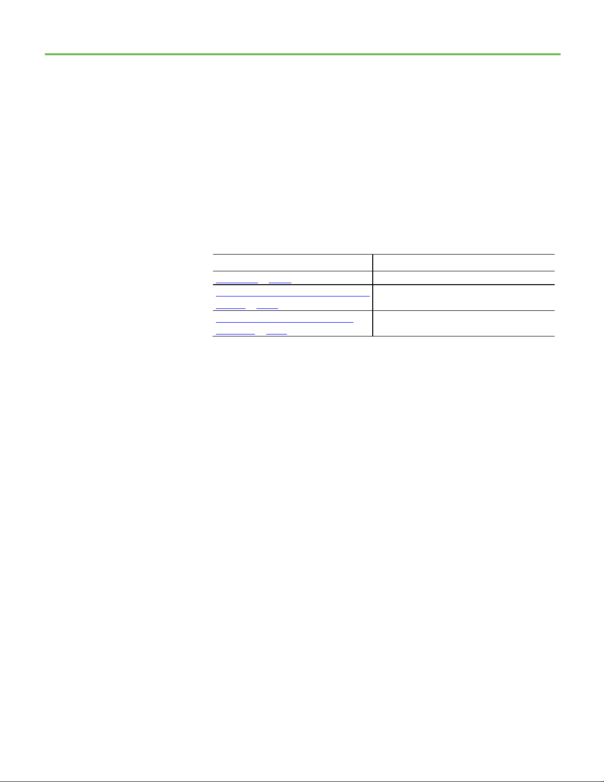
Summary of Changes
Topic Name
Reason
Modify the OPC quality code of a FactoryTalk
New topic.
This manual includes new and updated information. Use these reference
tables to locate changed information.
Global changes
None for this release.
New or enhanced features
This table contains a list of topics changed in this version, the reason for the
change, and a link to the topic that contains the changed information.
Create a node on page 12 Added step 4.
Edit an AOI with existing FactoryTalk Smart Object
instances on page 17
New topic.
Smart Object on page 11
Rockwell Automation Publication 95055-QS001B-EN-P - March 2021
3
Page 4

Page 5

Table of Contents
Summary of Changes
About Studio 5000 Smart Object
Configurator
Index
Preface
Studio 5000 environment .......................................................................... 7
Additional resources ................................................................................... 7
Legal notices ................................................................................................ 8
Chapter 1
Install Smart Object Configurator ............................................................ 9
Install base code .........................................................................................10
Rules for names and backing tags ............................................................ 11
Modify the OPC code quality value ........................................................... 11
Create a model ............................................................................................ 12
Create a node .............................................................................................. 12
Add a DINT data type to an information model ...................................... 14
Export FactoryTalk Smart Object configuration values .......................... 15
Import FactoryTalk Smart Object configuration values ......................... 16
Download a CSV template to create new FactoryTalk Smart Object
instances ..................................................................................................... 16
Edit an Add-On Instruction....................................................................... 16
Edit an Add-On Instruction with existing FactoryTalk Smart Object
instances ..................................................................................................... 17
Rockwell Automation Publication 95055-QS001B-EN-P - March 2021
5
Page 6

Page 7

Preface
Resource
Description
Studio 5000 environment
Additional resources
This manual shows how to use the Studio 5000 Smart Object Configurator to
gather metrics on specific data and deliver it to higher-level systems for
processing.
This manual is one of a set of related manuals that show common procedures
for programming and operating Logix 5000 controllers.
For a complete list of common procedures manuals, refer to the
Logix 5000
Controllers Common Procedures Programming Manual, publication 1756-
PM001.
The term Logix 5000 controller refers to any controller based on the Logix
5000 operating system.
The Studio 5000 Automation Engineering & Design Environment® combines
engineering and design elements into a common environment. The first
element is the Studio 5000 Logix Designer® application. The Logix Designer
application is the rebranding of RSLogix 5000® software and will continue to
be the product to program Logix 5000™ controllers for discrete, process,
batch, motion, safety, and drive-based solutions.
Th
e Studio 5000® environment is the foundation for the future of
Rockwell Automation® engineering design tools and capabilities. The Studio
5000 environment is the one place for design engineers to develop all
elements of their control system.
These documents contain additional information concerning related
Rockwell Automation products.
FactoryTalk Edge Gateway Quick Start Guide Provides guidelines for using FactoryTalk Edge
Gateway.
Logix 5000 Controllers I/O and Tag Data, publication
1756-PM004
Rockwell Automation Publication 95055-QS001B-EN-P - March 2021
This manual shows how to access I/O and tag data
in Logix5000 controllers.
7
Page 8

Preface
Resource
Description
execution of these tasks.
language.
Guidelines, publication 1770-4.1
Automation industrial system.
http://ab.rockwellautomation.com
and other certification details.
Legal notices
Logix 5000 Controllers Tasks, Programs, and
Routines, publication 1756-PM005
Logix 5000 Controllers Ladder Diagram, publication
1756-PM008
Industrial Automation Wiring and Grounding
Product Certifications webpage, available at
This manual details how to set up controllers tasks
along with the programs and routines for the proper
This manual shows how to program Logix 5000
controllers with the relay ladder programming
Provides general guidelines for installing a Rockwell
Provides declarations of conformity, certificates,
View or download publications at
http://www.rockwellautomation.com/literature
. To order paper copies of
technical documentation, contact the local Rockwell Automation distributor
or sales representative.
Rockwell Automation publishes legal notices, such as privacy policies, license
agreements, trademark disclosures, and other terms and conditions on the
Legal Notices
page of the Rockwell Automation website.
End User License Agreement (EULA)
You can view the Rockwell Automation End User License Agreement (EULA)
by opening the license.rtf file located in your product's install folder on your
hard drive.
The default location of this file is:
C:\Program Files (x86)\Common Files\Rockwell\license.rtf.
8
Rockwell Automation Publication 95055-QS001B-EN-P - March 2021
Page 9

Chapter 1
Studio 5000 Smart Object Configurator.
About Studio 5000 Smart Object Configurator
Studio 5000 Smart Object Configurator gathers metrics on specific data by
bundling the data and delivering it to higher-level systems for processing.
Use Studio 5000 Smart Object Configurator to:
• Turn existing Logix tags into FactoryTalk Smart Object instances by
extending existing base Logix tags with an additional set of userdefined configuration properties.
• Organize FactoryTalk Smart Object instances into information models
and define synchronous data collection based on the model hierarchy.
FactoryTalk® Edge Gateway™ consumes both the FactoryTalk Smart Object
information models and collected data and then delivers the contextualized
synchronous data to applications.
Configuration performed in Studio 5000 Smart Object Configurator transfers
to the controller and appears in parallel with the existing ladder logic.
Changes are not saved to the .acd file until the .acd file is saved in Logix 5000.
Tip: Use program-scoped tags to create FactoryTalk Smart Object instances in Studio 5000 Smart
Object Configurator. Creating controller-scoped FactoryTalk Smart Object causes an error on the
See also
Install base code on page 10
Install Smart Object Configurator
Use the Studio 5000 Smart Object Configurator common installer to install
Studio 5000 Smart Object Configurator.
Install Studio 5000 Smart Object Configurator on the same operating systems
that Studio 5000 Logix Designer® supports.
Tip: Studio 5000 Smart Object Configurator does not support Windows® 7.
Install Studio 5000 Smart Object Configurator alongside Studio 5000 Logix
Designer versions 28.00 to 33.00.
Rockwell Automation Publication 95055-QS001B-EN-P - March 2021
9
Page 10

Chapter 1 About Studio 5000 Smart Object Configurator
See also
Launch Studio 5000 Smart Object Configurator and install base code
on page 10
Install base code
Open the desired Logix application in Studio 5000 Logix Designer and then
launch Studio 5000 Smart Object Configurator.
Connect to a Studio 5000 Logix Designer .acd project file to run Studio 5000
Smart Object Configurator. To create a FactoryTalk Smart Object, the .acd
project file requires FactoryTalk Smart Object base code: program, routine,
and rung.
If FactoryTalk Smart Object base code is not in the project, install the
FactoryTalk Smart Object base code.
To install base code
1. Double-click an .acd project file.
2. In Studio 5000 Logix Designer, select Tools > Studio 5000 Smart
Object Configurator.
If the project includes FactoryTalk Smart Object base code, Studio
5000 Smart Object Configurator launches with the FactoryTalk Smart
Object information model.
3. If FactoryTalk Smart Object base code is not in the project, install the
FactoryTalk Smart Object base code.
a. In Select Destination, select a program. The program can be in the
fastest executing task within the project.
b. Select a routine. The routine must be ladder logic.
c. Select a rung number.
4. Select Add.
Code is injected into the controller. The Assets tab in the Controller
Organizer updates. A FactoryTalk Smart Object timer appears in the
ladder logic according to the location set for the FactoryTalk Smart
Object base code. A first element called Information model appears
in Studio 5000 Smart Object Configurator.
10
See also
Create a model on page 12
Rockwell Automation Publication 95055-QS001B-EN-P - March 2021
Page 11

Chapter 1 About Studio 5000 Smart Object Configurator
Rules for names and backing tags
These rules apply to names and backing tags:
Name
• Names must be unique for each node that is located under the same
parent level.
• Names are mandatory.
• Names are case insensitive.
• Names are limited to 40 Unicode characters and can be alphanumeric;
special characters are not supported.
• Spaces are supported, but not at the beginning or end of names.
• Names accept underscores.
Backing tag
• Backing tags follow the Studio 5000 Logix Designer naming rules.
• Backing tags are limited to 40 alphanumeric characters (ASCII);
special characters are not permitted.
• Backing tags cannot start with a number.
• Backing tags accept one underscore. Multiple underscores in a row are
not permitted. An underscore at the end is not permitted.
See also
Create a model on page 12
Create a node on page 12
Add a DINT data type to an information model on page 14
Modify the OPC code quality value
A FactoryTalk Smart Object transmits quality code values to FactoryTalk Edge
Gateway based on OPC quality. By default, the OPC quality code value in a
Studio 5000 Smart Object Configurator is 192.
Create logic in the Logix 5000 application to change the OPC quality values
that FactoryTalk Smart Object instances transmit to FactoryTalk Edge
Gateway.
To modify the OPC quality code value of a FactoryTalk Smart Object
1. In the Logix 5000 application, create logic as needed.
Rockwell Automation Publication 95055-QS001B-EN-P - March 2021
11
Page 12

Chapter 1 About Studio 5000 Smart Object Configurator
2. Move the new OPC value to the backing tag of the FactoryTalk Smart
Object (Smart Object.Inp_Quality).
Create a model
Create as many models as required for your FactoryTalk Smart Object
information model.
To create a model
1. Right-click Information models and then select Model.
2. In Model, set these basic properties:
• Name: Name of the model. See Rules for names and backing tags
• Backing tag: Name of the backing tag in the controller. A backing
tag is created in the Studio 5000 Logix Designer project that
contains the configuration information for the FactoryTalk Smart
Object.
• Program: Controller program where the model resides.
• Routine: Controller routine where the model resides. The routine is
ladder logic.
• Rung: Location to add a rung in the routine where the FactoryTalk
Smart Object appears.
• End of routine: Location at the end of the routine where the
FactoryTalk Smart Object appears.
The code appears in Studio 5000 Logix Designer.
See also
Create a node on page 12
Create a node
.
12
Use nodes to organize FactoryTalk Smart Object instances and to define how
FactoryTalk Smart Object instances are collected. A node does not sample a
specific tag’s value but instead defines the data collection mechanism for its
children. A node exists only as a folder in a hierarchy to provide structure for
the information model.
To create a node, set the node properties and then set the data collections
parameters. Node properties are saved in the .acd project file and define basic
information regarding the node.
Data collection parameters define how data is collected for FactoryTalk Smart
Object instances that are under a node that collects data based on the Parent
parameter. When data collection definition includes the Parent parameter,
Rockwell Automation Publication 95055-QS001B-EN-P - March 2021
Page 13

Chapter 1 About Studio 5000 Smart Object Configurator
data collected for a hierarchy based on this setting collects in the same
controller scan and has synchronized time stamps.
Data collection in Studio 5000 Smart Object Configurator is hierarchical and
by default data collection is based on the top level in the model. Break and reestablish the link between each node and it’s parent by using the Parent
parameter in the data collection configuration.
To create a node
1. Perform one of these actions:
• To add the first node, right-click Information models and then
select Node.
• To add a node under another node, right-click a node and then
select Node.
2. In Node, set these basic properties:
• Name: Name of the node displayed in the information model. See
Rules for names and backing tags
• Backing tag: Name of the backing tag created in the controller. A
backing tag is created in the Studio 5000 Logix Designer project
that contains the configuration information for the FactoryTalk
Smart Object.
• Program: Controller program where the node resides.
• Routine: Controller routine where the node resides.
• Rung: Location to add a rung in the routine where the FactoryTalk
Smart Object appears.
• End of routine: Location at the end of the routine where the
FactoryTalk Smart Object appears.
.
3. Set these data collection parameters:
• Triggers: When this check box is clear, and Programmatic trigger is
also clear, data collection for this node does not occur.
Tip: The first node requires Triggers or Periodic data collection parameters because it
does not have a parent.
It is possible to have multiple triggers active at once. Possible trigger combinations are:
Parent and Programmatic trigger or Periodic and Programmatic.
• Parent: When the parent is triggered, the FactoryTalk Smart
Object is also triggered.
• Periodic: Interval seconds at which point data is sampled in the
source tag.
• Programmatic trigger: Ladder logic that triggers the condition
for collection.
4. (Optional) Select ThingWorx, and then type the name of the template
to use for this node when mapping this model to a ThingWorx
instance.
Rockwell Automation Publication 95055-QS001B-EN-P - March 2021
13
Page 14

Chapter 1 About Studio 5000 Smart Object Configurator
Tip: The ThingWorx template:
• Cannot exceed 256 characters.
• Cannot contain three colons in a row (:::) or an ellipsis
(...).
• Cannot begin or end with a period (.) or a colon (:).
1. Select A
information model.
dd. The node appears in the FactoryTalk Smart Object
See also
Create a model on page 12
Add a DINT data type to an information model on page 14
Add a DINT data type to an information model
Add a DINT data type to a FactoryTalk Smart Object information model. Set
the basic collection properties to describe how the DINT FactoryTalk Smart
Object collects data.
To add a DINT data type to an information model
1. Right-click a node and then select DINT.
A DINT tab appears.
2. Set these basic properties:
• Name: Name of the data displayed in the information model. See
Rules for names and backing tags
• Backing tag: Name of the backing tag in the controller. A backing
tag is created in the Studio 5000 Logix Designer project that
contains the configuration information for the FactoryTalk Smart
Object.
• Source value tag (optional): Location where the data gathers.
• Program: Controller program where the node resides.
• Routine: Controller routine where the node resides.
• Rung: Location to add a rung in the routine where the FactoryTalk
Smart Object appears.
• End of routine: Location at the end of a routine where the
FactoryTalk Smart Object appears.
3. Set these data collection parameters:
• Triggers: When this check box is clear, and Programmatic trigger is
also clear, data collection for this data value does not occur.
Tip: It is possible to have multiple triggers active at once.
.
14
Rockwell Automation Publication 95055-QS001B-EN-P - March 2021
Page 15

• Programmatic trigger: Ladder logic that triggers the condition for
• On change: Data is sampled each time that it changes based on the
4. Select Add.
A new rung appears in the ladder logic. The DINT FactoryTalk Smart
Object appears in the FactoryTalk Smart Object tree. Initials
representing the trigger types, for example, P +T+CH, appear next to
the model name.
See also
Create a model on page 12
Chapter 1 About Studio 5000 Smart Object Configurator
• Parent: When Parent is triggered, the FactoryTalk Smart Object
is also triggered.
• Periodic: Interval in seconds when data is sampled in the source
tag.
collection.
value in engineering units (positive number).
Create a node on page 12
Export FactoryTalk Smart Object configuration values
Export FactoryTalk Smart Object configuration values to a CSV file to quickly
update values. Use the CSV file to filter, and modify FactoryTalk Smart Object
configuration values.
After modifying the FactoryTalk Smart Object configuration values in the CSV
file, import the FactoryTalk Smart Object configuration values to Studio 5000
Smart Object Configurator.
To export FactoryTalk Smart Object configuration values
1. Go to Functions > Modify Existing > Export.
2. Select a location and type a file name.
A CSV file is created.
3. Select Save.
4. Modify the spreadsheet. Columns that are read-only contain (r) in the
column header.
See also
Import FactoryTalk Smart Object configuration values on page 16
Rockwell Automation Publication 95055-QS001B-EN-P - March 2021
15
Page 16

Chapter 1 About Studio 5000 Smart Object Configurator
Documents folder. Consult the log file for a list of rows that contain errors.
Import FactoryTalk Smart Object configuration values
After exporting and then updating FactoryTalk Smart Object configuration
values in a CSV file, import the new FactoryTalk Smart Object configuration
values to Studio 5000 Smart Object Configurator.
Tip: If an import error occurs, FactoryTalk Smart Object creates a log file in the Windows
To import FactoryTalk Smart Object configuration values
1. Go to Functions > Modify existing > Import.
2. Select a file.
3. Select Open.
The changes to the configuration values appear in the information
model.
See also
Export FactoryTalk Smart Object configuration values on page 15
Download a CSV template to create new FactoryTalk Smart Object instances
Download a CSV template that contains the columns required for creating
FactoryTalk Smart Object instances.
After using the CSV template to quickly create new FactoryTalk Smart Object
instances, import the new FactoryTalk Smart Object instances into Studio
5000 Smart Object Configurator.
To download a CSV template to create new FactoryTalk Smart Object
instances
1. Select Functions > Create new > Download Template.
2. Select a folder and then type a name for the file.
3. Select Save.
Edit an Add-On Instruction
Use Studio 5000 Smart Object Configurator to edit Add-On Instructions
(AOIs).
16
Rockwell Automation Publication 95055-QS001B-EN-P - March 2021
An empty template appears in your folder.
Page 17

Chapter 1 About Studio 5000 Smart Object Configurator
To edit an Add-On Instruction
1. Select Functions > Edit AOI.
2. Select an AOI.
The AOI appears in a separate tab.
3. Add an information model to the AOI.
See also
Create a model on page 12
Create a node on page 12
Edit an Add-On Instruction with existing FactoryTalk Smart Object instances
Upon creation, an Add-On Instruction (AOI) inherits values from the
definition. After AOI creation, manually push new AOI definition changes to
the instances.
To edit an Add-On Instruction with existing FactoryTalk Smart Object
instances
1. Select Functions > Edit AOI.
2. Select an AOI.
The AOI appears in a separate tab.
3. Perform one of these actions:
• Add a data type or node, and then select Done.
• Change the name and then select Update.
4. Verify that the AOI model is correct.
5. In Studio 5000 Logix Designer, go to the logic of the AOI and then
monitor a tag.
6. In Copy default values to tags of type, select Copy Specified Values.
7. Select the local tag for the modified FactoryTalk Smart Object and then
select OK.
8. Download the Studio 5000 Logix Designer project to a controller or
emulator.
9. Put the controller in Run mode for at least 5 seconds. Save and then
upload the values.
10. In Studio 5000 Smart Object Configurator, select Reconnect.
The information models reflect the changes.
Rockwell Automation Publication 95055-QS001B-EN-P - March 2021
17
Page 18

Chapter 1 About Studio 5000 Smart Object Configurator
is no need to download the project.
See also
Edit an Add-On Instruction on page 16
Tip: To delete a FactoryTalk Smart Object inside an AOI, in Studio 5000 Logix Designer
delete the code and backing tag. Reconnect Studio 5000 Smart Object Configurator. There
18
Rockwell Automation Publication 95055-QS001B-EN-P - March 2021
Page 19

Index
.
.acd project file 10
A
AOI 16
B
base code 10
C
CSV file 15
CSV template 16
Index
I
information models 11
N
naming rules 10
nodes 12
O
OPC quality 11
T
ThingWorx 12
Rockwell Automation Publication 95055-QS001B-EN-P - March 2021
19
Page 20

Rockwell Automation support
Technical Support Center
updates.
Knowledgebase
Access Knowledgebase articles.
rok.auto/knowledgebase
Literature Library
find associated firmware.
Use these resources to access support information.
Local Technical Support Phone Numbers
Product Compatibility and Download Center
(PCDC)
Find help with how-to videos, FAQs, chat, user forums, and product notification
Locate the telephone number for your country. rok.auto/phonesupport
Find installation instructions, manuals, brochures, and technical data publications. rok.auto/literature
Get help determining how products interact, check features and capabilities, and
rok.auto/support
rok.auto/pcdc
Documentation feedback
Your comments help us serve your documentation needs better. If you have any suggestions on how to improve our content, complete the form at
rok.auto/docfeedback
.
Waste Electrical and Electronic Equipment (WEEE)
At the end of life, this equipment should be collected separately from any unsorted municipal waste.
Rockwell Automation maintains current product environmental information on its website at rok.auto/pec.
Allen-Bradley, expanding human possibility, Logix, Rockwell Automation, and Rockwell Software are trademarks of Rockwell Automation, Inc.
EtherNet/IP is a trademark of ODVA, Inc.
Trademarks not belonging to Rockwell Automation are property of their respective companies.
Rockwell Otomayson Ticaret A.Ş. Kar Plaza İş Merkezi E Blok Kat:6 34752, İçerenkÖy, İstanbul, Tel: +90 (216) 5698400 EEE YÖnetmeliğine Uy gundur
Rockwell Automation Publication 95055-QS001B-EN-P - March 2021
upersedes Publication 95055-QS001A-EN-P - November 2020
S
Copyright © 2021 Rockwell Automat ion Technologies, Inc. All Rights Reserved. Printed in the U.S.A.
 Loading...