

Page 1

Original Instructions
Studio 5000 View Designer User Manual
Publication 9324-UM001D-EN-D
Page 2
Studio 5000 View Designer User Manual
personal injury or death, property damage, or economic loss.
IMPORTANT
for Personal Protective Equipment (PPE).
Important User Information
Read this document and the documents listed in the additional resources section about installation, configuration, and
operation of this equipment before you install, configure, operate, or maintain this product. Users are required to familiarize
themselves with installation and wiring instructions in addition to requirements of all applicable codes, laws, and standards.
Activities including installation, adjustments, putting into service, use, assembly, disassembly, and maintenance are required to
be carried out by suitably trained personnel in accordance with applicable code of practice.
If this equipment is used in a manner not specified by the manufacturer, the protection provided by the equipment may be
impaired.
In no event will Rockwell Automation, Inc. be responsible or liable for indirect or consequential damages resulting from the use
or application of this equipment.
The examples and diagrams in this manual are included solely for illustrative purposes. Because of the many variables and
requirements associated with any particular installation, Rockwell Automation, Inc. cannot assume responsibility or liability for
actual use based on the examples and diagrams.
No patent liability is assumed by Rockwell Automation, Inc. with respect to use of information, circuits, equipment, or software
described in this manual.
Reproduction of the contents of this manual, in whole or in part, without written permission of Rockwell Automation, Inc., is
prohibited.
Throughout this manual, when necessary, we use notes to make you aware of safety considerations.
WARNING: Identifies information about practices or circumstances that can cause an explosion in a hazardous environment, which may lead to
ATTENTION: Identifies information about practices or circumstances that can lead to personal injury or death, property damage, or economic loss.
Attentions help you identify a hazard, avoid a hazard, and recognize the consequence.
Identifies information that is critical for successful application and understanding of the product.
Labels may also be on or inside the equipment to provide specific precautions.
SHOCK HAZARD: Labels may be on or inside the equipment, for example, a drive or motor, to alert people that dangerous voltage may be present.
BURN HAZARD: Labels may be on or inside the equipment, for example, a drive or motor, to alert people that surfaces may reach dangerous
temperatures.
ARC FLASH HAZARD: Labels may be on or inside the equipment, for example, a motor control center, to alert people to potential Arc Flash. Arc Flash
will cause severe injury or death. Wear proper Personal Protective Equipment (PPE). Follow ALL Regulatory requirements for safe work practices and
2 Rockwell Automation Publication 9324-UM001D-EN-D - September 2020
Page 3
Topic Name
Reason
Alarm History Large on page 450
New topic.
Alarm History Medium on page 452
New topic.
select a Screen Scaling option on page 61
Details pane rows on page 334
Added information regarding Alarm History.
page 354
on page 356
table on page 355
Image on page 467
Added ImageName property.
the System Banner on page 101
Alarm table filters on page 370
Added information regarding Alarm History.
Filter alarms on page 851
Added information regarding Alarm History.
log export.
What is an event? on page 277
Added information regarding alarm history export.
on page 918
Summary of changes
This manual includes new and updated information. Use these reference
tables to locate changed information.
Global changes
None for this release.
New or enhanced features
This table contains a list of topics changed in this version, the reason for the
change, and a link to the topic that contains the changed information.
Change the target HMI device for a project and
Application tab on page 59 Added keyboard and keypad size information.
Alarm History on page 353 New topic.
Alarm History contents for a large HMI device
screen on page 357
Alarm History contents for a medium HMI
device screen on page 358
Alarm History table columns on page 359 New topic.
Alarm History table columns on page 834 New topic.
Add a column to an Alarm History table on
Delete a column from an Alarm History table
Change the order of columns in Alarm History
Change the width of a column in an Alarm
History table on page 354
Change the update rate of a screen, popup, or
Added keyboard and keypad size information.
New topic.
New topic.
New topic.
New topic.
New topic.
New topic.
New topic.
Rockwell Automation Publication 9324-UM001D-EN-D - September 2020 3
Event commands on page 259 Added information regarding alarm history export and data
System tags: Alarms on page 686 Added information regarding alarm history export.
Unable to download or upload the HMI project
Draw an arc on page 412 New topic.
New topic.
Page 4
Studio5000 environment_View Designer
Topic Name
Reason
ProjectEvents and SMTP.
System tags: Alarms on page 686
Added information regarding alarm history export.
System tags: DataLogs on page 688
New topic.
System tags: ProjectEvents on page 692
New topic.
System tags: SMTP on page 693
New topic.
Export alarm history on page 868
New topic.
870
Export a data log on page 877
Updated information regarding data log export.
Cancel the export of a data log on page 879
Updated information regarding data log export.
page 272
Cannot export data to SD card on page 910
Added a solution.
Alarms overview on page 313
Added information regarding Alarm History.
47
852
Help popup for alarm tables on page 337
Added information regarding Alarm History.
Help popup for alarm tables on page 845
Added information regarding Alarm History.
Help popup on page 844
Added information regarding Alarm History.
Navigation menu contents on page 302
Added information regarding Alarm History.
page 237
number of states.
page 239
number of states.
Alarm history retention on page 838
New topic.
Alarm history file on page 871
New topic.
Change the value of a filter on page 368
Added information regarding Alarm History.
Sort alarms on page 850
Added information regarding Alarm History.
What are system tags? on page 685 Added information for Alarms, Auto-Logoff, Data Logs,
System tags: AutoLogoff on page 687 New topic.
Cancel the export of alarm history on page
Add an event command to export a data log on
New topic.
Updated information regarding data log export.
Settings screen on page 782 Updated information regarding data log export.
What is the Settings screen? on page 86 Updated information regarding data log and alarm history
export.
System Banner contents on page 772 Updated information regarding data log and alarm history
export.
View the default content of a project on page
Filter Alarm History by Event Time on page
Added information regarding Alarm History.
New topic.
Predefined Screens folder on page 85 Added information regarding Alarm History.
4 Rockwell Automation Publication 9324-UM001D-EN-D - September 2020
Configure an animation using a State Table on
Configure an animation using a Color Table on
Added information regarding the maximum supported
Added information regarding the maximum supported
Page 5
Resource
Description
http://ab.rockwellautomation.com
and other certification details.
2713P-UM001
troubleshoot the PanelView 5300 terminals.
publication 2715-UM001
troubleshoot the PanelView 5500 terminals.
Additional resources
These documents contain additional information concerning related
Rockwell Automation products.
Preface
Industrial Automation Wiring and Grounding
Guidelines, publication 1770-4.1
Product Certifications webpage, available at
<PV First> 5300 Terminals User Manual publication
PanelView 5500 Terminals User Manual
Provides general guidelines for installing a Rockwell
Automation industrial system.
Provides declarations of conformity, certificates,
Describes how to install, configure, operate, and
Describes how to install, configure, operate, and
View or download publications at
http://www.rockwellautomation.com/literature
. To order paper copies of
technical documentation, contact the local Rockwell Automation distributor
or sales representative.
Rockwell Automation publishes legal notices, such as privacy policies, license
agreements, trademark disclosures, and other terms and conditions on the
Legal Notices
page of the Rockwell Automation website.
End User License Agreement (EULA)
You can view the Rockwell Automation End User License Agreement (EULA)
by opening the license.rtf file located in your product's install folder on your
hard drive.
The default location of this file is:
C:\Program Files (x86)\Common Files\Rockwell\license.rtf.
Other Licenses
The software included in this product contains copyrighted software that is
licensed under one or more open source licenses. Copies of those licenses are
included with the software. Corresponding Source code for open source
packages included in this product can be located at their respective web
site(s).
You may alternately obtain complete Corresponding Source code by
contacting Rockwell Automation via our Contact form on the Rockwell
Automation website:
us/contact/contact.page
Please include "Open Source" as part of the request text.
http://www.rockwellautomation.com/global/about-
Rockwell Automation Publication 9324-UM001D-EN-D - September 2020 5
Page 6

A full list of all open source software used in this product and their
corresponding licenses can be found in the OPENSOURCE folder
included
with these Release Notes. The default installed location of these licenses is
C:\Program Files (x86)\Common Files\Rockwell\Help\Studio 5000 View
Designer Help\V6\ReleaseNotes\OPENSOURCE\index.htm.
6 Rockwell Automation Publication 9324-UM001D-EN-D - September 2020
Page 7

Table of Contents
SUMMARY OF CHANGES
Additional resources 5
CHAPTER 1
VIEW DESIGNER
View Designer 15
CHAPTER 2
CREATE A PROJECT IN VIEW DESIGNER
Create a project 41
CHAPTER 3
SELECT AN HMI DEVICE
Select an HMI device 57
CHAPTER 4
ADD A CONTROLLER REFERENCE
Add a controller reference 75
References tab 77
Browse for Controller window 78
Copy a controller reference 78
Remove a controller reference 79
Remove a controller from the network tree 80
Synchronization 80
Synchronization between Logix Designer and View Designer 81
Synchronization: Controller state indicator icons 81
Synchronization between the runtime application and the controller 82
Tag browsing in a secured Logix Designer project file 82
View the default content of a project 83
Project Explorer 83
Predefined Screens folder 85
What is the System Banner? 86
What is the Settings screen? 86
What is the Alarm Summary? 88
What is the Alarm Manager? 88
CHAPTER 5
SCREENS
Work with screens 91
CHAPTER 6
SHORTCUTS
Work with shortcuts 103
Rockwell Automation Publication 9324-UM001D-EN-D - September 2020 7
Page 8

New Shortcut dialog box 103
Shortcut tab 104
Create a shortcut to an existing screen 105
Create a shortcut to a new screen 106
Open a shortcut 108
Rename a shortcut 108
Copy a shortcut 109
Open the defining screen of a shortcut 110
Shortcut customization 110
Close a shortcut 111
Delete a shortcut 112
What is a shortcut? 112
CHAPTER 7
POPUPS
Work with popups 115
Popup tab 115
Create a popup 116
Open a popup 117
Copy a popup 117
Change the caption on a popup 119
Remove the caption from a popup 119
Remove the Close button from a popup 120
Change the background color of a popup 121
Change the opacity of a popup 121
Resize a popup 122
Rename a popup 123
Delete a popup 123
Close a popup 124
Restore the default content of a predefined item 124
Change the update rate of a screen, popup, or the System Banner 125
What is a popup? 126
Popup contents 126
CHAPTER 8
SYSTEM BANNER
System Banner 129
Banner tab 129
Open the System Banner 130
Change the height of the System Banner 130
Change the background color of the System Banner 131
Add a graphic element to the System Banner 132
Copy and paste a graphic element on the System Banner 133
Remove a graphic element from the System Banner 134
Remove the System Banner from a screen 134
Close the System Banner 135
Restore the default content of a predefined item 135
Change the update rate of a screen, popup, or the System Banner 136
System Banner contents 137
What is the System Banner? 138
8 Rockwell Automation Publication 9324-UM001D-EN-D - September 2020
Page 9

Table of Contents
CHAPTER 9
ADD A GRAPHIC ELEMENT TO A PROJECT
Add a graphic element to a project 141
Toolbox 141
Graphic Explorer 142
Lock or unlock graphic elements 143
CHAPTER 10
UNDO AND REDO AN ACTION
Undo an action 145
Redo an action 146
CHAPTER 11
REUSE CONTENT
Reuse content 147
Reuse screens and popups 147
Example of content reuse 147
Property Definition tab 149
Create an alias property 149
Properties that do not support aliasing 151
User-defined alias type property binding 152
Create a user-defined property with a data type 153
User-defined data type property binding 155
Change a user-defined property 156
Propagation of changes to a user-defined property 157
Delete a user-defined property 159
User-defined property 159
Link a user-defined property to its base property 160
Unlink a user-defined property from its base property 161
Select a data type 162
Data Type Browser 162
Search for and select a data type 163
Add-On Graphics 164
Changes to size 174
Changes to user-defined properties 174
Changes to aliased properties 174
Reuse content from other View Designer projects 220
CHAPTER 12
CREATE ANIMATION
Change an animation 233
Animate a graphic element or screen 233
Create an HMIBC Button 244
CHAPTER 13
CONFIGURE AN EVENT TO TRIGGER AN ACTION
Configure an event to trigger an action 249
Rockwell Automation Publication 9324-UM001D-EN-D - September 2020 9
Page 10

CHAPTER 14
CHANGE A PROPERTY
Change a property 293
Properties window 293
Properties tab 294
List of properties 295
CHAPTER 15
FIND AND REPLACE
Find and replace 297
Find and Replace dialog box 297
Find text in a project 298
Find and replace text in a project 299
Find Results window 300
CHAPTER 16
PROJECT NAVIGATION
Project navigation 301
CHAPTER 17
DISPLAY ALARMS
Display alarms 313
CHAPTER 18
DISPLAY DATA ON A TREND CHART
Display data on a trend chart 373
CHAPTER 19
WORK WITH PDF DOCUMENTS
Work with PDF documents 393
CHAPTER 20
DRAWING TOOLS
Use drawing tools 411
Draw a rectangle or square 411
Draw a line, polyline, or polygon 412
Draw an oval or circle 412
Draw an arc 412
CHAPTER 21
GRAPHIC ELEMENTS
Work with graphic elements 415
10 Rockwell Automation Publication 9324-UM001D-EN-D - September 2020
Page 11

Table of Contents
Find a graphic element in the Toolbox 415
Add a graphic element to a screen 417
Select a graphic element on a screen 418
Select a graphic element in the Graphic Explorer 418
Copy a graphic element 419
Delete a graphic element 420
Change the properties of a graphic element 420
Change the text in a graphic element 421
Select a text color 422
Select a fill color 422
Move a graphic element 423
Rotate a graphic element 424
Flip a graphic element 425
Resize a graphic element 426
Align graphic elements 426
Smart Guides 428
Change the stacking order of graphic elements and groups 431
Distribute graphic elements 431
Duplicate a graphic element 433
Group graphic elements 433
Zoom in or zoom out 434
Add a Slider 434
What is a Slider? 436
CHAPTER 22
GRAPHIC ELEMENTS LIBRARY
Graphic elements library 437
CHAPTER 23
WORK WITH GROUPS
Group graphic elements 615
Add a graphic element or a group to a group 616
Remove a graphic element or a group from a group 616
Work with individual graphic elements in a group 617
Lock or unlock groups 617
Resize a group 618
Flip a group 619
Rotate a group 620
Move a group 620
Align groups 621
Change the stacking order of graphic elements and groups 623
Cut, copy, or paste a group 624
Duplicate a group 625
Ungroup graphic elements 625
Work with images 625
Add an image to the Images folder 626
Add an image to a project 627
Copy an image between View Designer projects 628
Select Image dialog box 629
Add an image to a screen 630
Preview an image 631
Rename an image 632
Delete an image from the Images folder 632
Replace an image on a screen 633
Rockwell Automation Publication 9324-UM001D-EN-D - September 2020 11
Page 12

Rename an image in the Images folder 633
Replace an image throughout a project 634
Delete an image from a project 635
Image naming conventions 635
CHAPTER 24
SELECT OR CREATE A COLOR
Select a color using the Color Picker 637
Color Picker 638
Color Picker overview 638
Create a custom color using the Color Picker 639
Create a color gradient 640
Select a fill color 641
Select a text color 642
Bind a color property to a tag or expression 643
Supported color keywords and RGB values 644
CHAPTER 25
BIND PROPERTIES
Bind properties 645
What is binding? 645
Bind a property to a data item 646
Bind a color property to a tag or expression 648
Property-to-property binding 649
Supported color keywords and RGB values 651
Properties that do not support binding 651
Remove a binding 652
Verify controller tags 653
Verify Project dialog box 653
Errors window 654
CHAPTER 26
BIND TO THE EXTENDED PROPERTIES OF A TAG
Bind to the extended properties of a tag 657
Assign the extended properties of a tag to a graphic element 657
What are extended properties? 658
Graphic element configured with extended properties 660
Extended properties and aliases 661
CHAPTER 27
USE EXPRESSIONS
Use expressions 663
Expressions overview 663
Expression Editor 665
Create an expression 665
Change an expression 667
Errors window 668
Nest conditional expressions 668
Verify expressions 669
Expression examples 670
12 Rockwell Automation Publication 9324-UM001D-EN-D - September 2020
Page 13

How are expressions evaluated? 675
Supported expression components 676
CHAPTER 28
BIND TO SYSTEM TAGS
Bind to system tags 685
What are system tags? 685
System tags: Alarms 686
System tags: AutoLogoff 687
System tags: Controller 687
System tags - Controller: SyncState values 688
System tags: DataLogs 688
System tags: DateTime 689
System tags: Device 689
System tags: Display 690
System tags: Enet 691
System tags: EnetLink1 and EnetLink2 692
System tags: ProjectEvents 692
System tags: Security 693
System tags: SMTP 693
System tags: VNC 694
Table of Contents
CHAPTER 29
USE THE TAG BROWSER AND THE DATA TYPE BROWSER
Use the Tag Browser and the Data Type Browser 695
Overview of the Tag Browser and the Data Type Browser interface 695
Tag Browser and Data Type Browser customization methods 698
Breadcrumb navigation in the Tag Browser and the Data Type Browser 698
Keyboard shortcuts for the Tag Browser and the Data Type Browser 699
Tag Browser 700
Search for and select a tag 701
Tag Browser operators 702
Tag Browser filters 703
CHAPTER 30
LOG DATA
Log data 705
Add a data log to a project 706
CHAPTER 31
SWITCH LANGUAGES
Switch languages on the HMI device 727
Export Languages dialog box 727
Export text strings for language translation 728
Import Languages dialog box 729
Import a language file 730
Add a language to a View Designer project 731
Add an event command to change the language on the HMI device 732
Remove a language from a View Designer project 733
Language handling and STRING data type support in View Designer 734
Rockwell Automation Publication 9324-UM001D-EN-D - September 2020 13
Page 14

About changing the project language 735
CHAPTER 32
EMULATE A PROJECT
Emulate a project 737
CHAPTER 33
DATA TYPE BROWSER
Data Type Browser 745
Search for and select a data type 745
Data Type Browser operators 747
Data Type Browser filters 747
CHAPTER 34
SET SECURITY
Set security 749
CHAPTER 35
USE THE RUNTIME APPLICATION
Use the runtime application 769
CHAPTER 36
DOWNLOAD AND UPLOAD A PROJECT
Download and upload a project 883
CHAPTER 37
DOWNLOAD A RUNTIME APPLICATION
Download a runtime application to an HMI device 885
CHAPTER 38
UPLOAD A RUNTIME APPLICATION
Upload a runtime application from an HMI device 897
CHAPTER 39
TROUBLESHOOT
Troubleshoot 905
STUDIO5000 ENVIRONMENT_VIEW DESIGNER
CHAPTER 40
STUDIO 5000 VIEW DESIGNER HELP
14 Rockwell Automation Publication 9324-UM001D-EN-D - September 2020
Page 15
Item
Name
Description
the View Designer project.
the Tag Browser to read data from the ACD file.
a .vpd extension.
View Designer
Chapter 1
View Designer
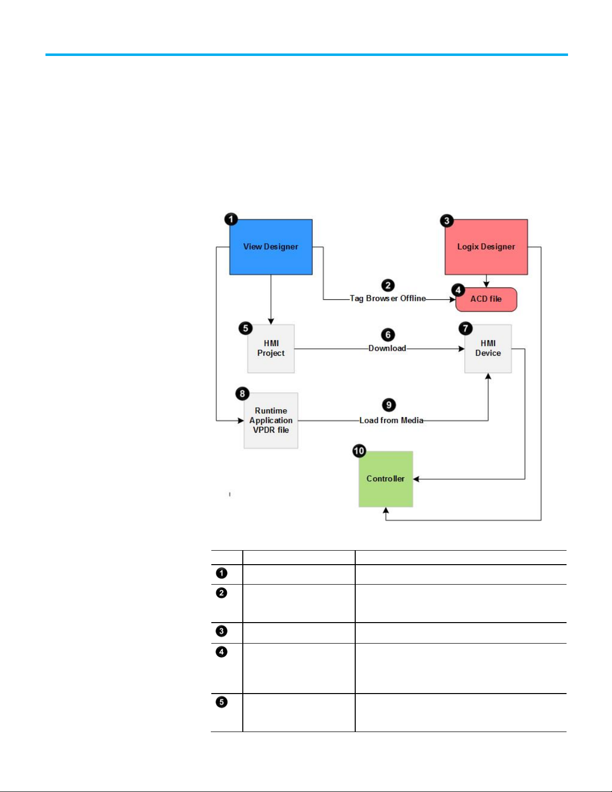
The following diagram shows how View Designer works with the Studio 5000
suite to create a control and visualization system to monitor and control the
manufacturing process.
Rockwell Automation Publication 9324-UM001D-EN-D - September 2020 15
View Designer Build the projects that are downloaded to an HMI device.
Tag Browser
Logix Designer Develop control logic for an industrial automation system.
ACD file
HMI project
Search for and select tags within a Logix Designer project file to
bind the tags to the properties of graphic elements and screens in
The Automation Control Database (ACD) file that is the Logix
Designer project file containing the logic or code, including tags
and data types, that runs within a controller. View Designer uses
The user-defined screens, controller references, information about
the target HMI device, and so forth. Projects are stored in files with
Page 16
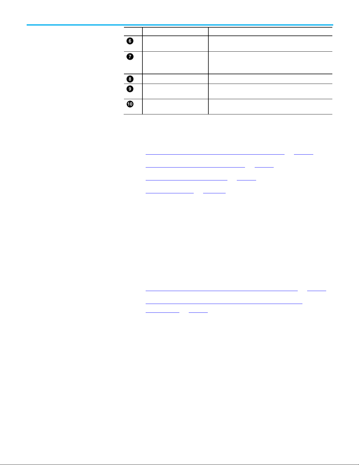
Chapter 1 View Designer
Item
Name
Description
communicates directly with the controllers.
as an SD Card or USB storage device to the HMI device.
project.
FactoryTalk View Machine
FactoryTalk View Machine
View Designer Download Runtime
Application Wizard
HMI device
VPDR file Save a Runtime Application VPDR file from View Designer.
Load from media
Controller
See also
Gather process and system requirement information on page 37
What types of HMI screens do I need? on page 37
Define conventions for screens on page 39
Project navigation on page 301
Transfer the HMI project to the HMI device.
The Human Machine Interface (HMI) device, such as a PanelView
5000 device, that runs the HMI project. At runtime, the HMI device
Load a Runtime Application VPDR file from removable media such
A controller with the ACD file and tags used in the View Designer
Edition (ME) vs View
Designer
Edition (ME) vs View
Designer
View Designer is not a replacement for FactoryTalk View Machine Edition
(ME); however, it provides many of the same features.
When familiar with working in FactoryTalk ME, review the differences in
functionality and terminology.
See also
FactoryTalk View Machine Edition (ME) vs View Designer on page 16
FactoryTalk View Machine Edition (ME) vs View Designer:
Terminology on page 17
Although View Designer is not a replacement for FactoryTalk View ME (ME),
it provides many of the same features. However, there are significant
differences in the performing some tasks:
• Set up communications
• Create a navigation menu
• Setup security
• Display alarms and alarm messages
• Change the appearance and behavior of graphic elements
• Display runtime diagnostics
• Pass parameter to a screen
• Format color values
16 Rockwell Automation Publication 9324-UM001D-EN-D - September 2020
Page 17
FactoryTalk View ME term
View Designer equivalent term
Object Explorer
Graphic Explorer
On Top display
popup
operator interface application
HMI project
parameter files
screen properties
Symbol Factory
Extensive built-in graphics library
tag placeholders
user-defined alias properties or data type properties
FactoryTalk View Machine
Edition (ME) vs View
View ME ViewE: Change the
Chapter 1 View Designer
See also
View ME ViewE: Create a navigation menu on page 18
View ME ViewE: Display alarms and alarm messages on page 18
View ME ViewE: Change the appearance and behavior of graphic
elements on page 17
View ME ViewE: Pass parameters to a screen on page 19
ViewME ViewE: Format color values on page 20
The following table provides the View Designer equivalent of some
FactoryTalk View Machine Edition (ME) terms.
Designer: Terminology
appearance and behavior of
graphic elements
graphic object graphic element
Studio Designer
project file (.med) project file (.vpd)
shortcut or device shortcut controller reference
See also
• FactoryTalk View Machine Edition (ME) vs View Designer on page 16
•
FactoryTalk View ME (ME) provides various dialog boxes to change the
appearance and behavior of objects. It also provides several editors for
configuring animations such as changing the color of an object.
View Designer provides a Properties window on the main interface to
configure the appearance and behavior of the selected screen or graphic
element. This includes configuring events and animation, and selecting tags
to bind to properties. Bind most graphic element properties, such as opacity,
directly.
Rockwell Automation Publication 9324-UM001D-EN-D - September 2020 17
See also
Properties window on page 293
Page 18

Chapter 1 View Designer
View ME ViewE: Create a
View ME ViewE: Display
navigation menu
alarms and alarm
In FactoryTalk View Machine Edition (ME), the display list selector object
shows a list of displays from which to choose. Scroll through the list and select
the display to open. Opening the display requires security access.
In View Designer, drag and drop screen shortcuts into the Navigation Menu
folder on the Project Properties window. Organize the contents of a project
into folders and subfolders. View Designer creates a Navigation menu based
on the structure of the contents of the Navigation Menu folder. Screens that
have security access for the logged in user appear in the Navigation Menu.
See also
How do I create navigation for the HMI screens? on page 32
In FactoryTalk View ME (ME), use the Alarm Setup editor to set up alarm
triggers (the tags or expressions to monitor), define alarm messages, and so
forth. Use the default [ALARM] display or create a graphic display.
messages
View ME ViewE: Display
runtime diagnostics
In Studio 5000 Logix Designer, program Logix Designer alarm detection
instructions in a Logix controller and reference that controller in a View
Designer project. View Designer provides pre-configured Alarm Summary or
Alarm Manager tables to display the alarm data and messages. The alarm
tables receive the alarm data automatically; configuration and tag binding is
not required.
Every View Designer project contains an Alarm Summary screen and a Alarm
Manager screen by default. Create alarm screens by dragging the Alarm
Manager or Alarm Summary graphic elements onto the screen.
See also
Create an alarm screen on page 316
FactoryTalk View ME (ME) uses FactoryTalk Diagnostics to record various
types of system activity such as:
• System messages and errors.
• Errors from the communication network.
• Tag read and write activity.
18 Rockwell Automation Publication 9324-UM001D-EN-D - September 2020
Configuring the severity of a system activity to log adds a message to the list
when the activity occurs. The list appears in the default [DIAGNOSTICS]
display or user-created display.
Page 19
View ME ViewE: Pass
Chapter 1 View Designer
View Designer provides several options for monitoring system health,
network communications, and tag read and write activity in a project. The
Predefined Screens folder in the Project Explorer contains:
• Alarm Summary, Alarm Manager and Alarm History screens to
monitor alarms set up in the controller.
• Troubleshooting screen to collect data and export a log to external
media.
• NetworkDiagnostic screen and ControllersDiagnostic screen to
troubleshoot network and controller problems.
The Toolbox contains alarm graphic elements used to create screens.
On the HMI device, errors are indicated for a graphic element when the
graphic element or group of graphic elements is outlined in red and has an
Error icon . Select the Error icon to view the Error list, which
contains a snapshot of the diagnostic messages associated with a graphic
element or group of graphic elements in error.
parameters to a screen
See also
View error messages for a graphic element on page 813
In FactoryTalk View ME (ME), create tag placeholders in graphic displays and
then create a parameter file or a parameter list. This specifies which tags or
folders to substitute for which placeholders when a display opens at runtime.
In View Designer, pass tag values from controllers to a screen or popup by
defining properties and exposing them for re-use. These user-defined
properties can be aliases of existing screen properties or properties that have
a data type. Data type properties replace a specific Logix Designer tag
instance when configuring bindings and expressions on the screen. To pass
the correct tag context to use at runtime, create a navigation event or a
shortcut to the screen.
In addition to passing tag values from controllers to a screen, pass the values
of non-alias screen properties from one screen to non-alias screen properties
of another screen with each target screen acting on the data associated with
its source screen. This chains reusable screens together by passing tag values
to the first screen, when then passes the values to subsequent screens.
Rockwell Automation Publication 9324-UM001D-EN-D - September 2020 19
See also
Example of content reuse on page 147
Page 20

Chapter 1 View Designer
View ME ViewE: Set up
ViewME ViewE: Format
Learn
communications
FactoryTalk View ME (ME) requires specifying and configuring an
FactoryTalk® Linx™ or OPC server, configuring the path between the data
server and each controller, and adding device tags to the tag database for the
application.
In View Designer, set up an Ethernet driver in RSLinx Classic. Use the
Application tab on the Project Properties dialog box to select the HMI device
for the project. Use the References tab to add and configure the controller
references. Both tabs contain integrated browsers for selecting the HMI
device, controller, and Logix project file and setting up the appropriate
communication paths. Manually enter an IP address and slot number for the
controller instead of browsing for the path.
See also
Project Properties dialog box on page 59
color values
When binding a color property to a tag or expression, the string tag or
expression in View Designer resolves to the format #RRGGBB. R, G, B are the
Hex digits that represent the value for the red, green, and blue color channels.
For example, in View Designer, the string "#ffff00" produces yellow.
FactoryTalk View Machine Edition (ME) and FactoryTalk View Site Edition
(SE) use the format #BBGGRR. Change this format to #RRGGBB for color
property strings and expressions in View Designer.
See also
FactoryTalk View Machine Edition (ME) vs View Designer on page 16
This section provides step-by-step direction to perform some basic tasks in
View Designer:
• Animate a graphic element
• Configure a button with an event
• Display values on graphic elements
• Reuse screens
• Trigger an action on a screen or graphic element
• Set up security
• Create navigation on the HMI device
• Display alarm data from controllers
20 Rockwell Automation Publication 9324-UM001D-EN-D - September 2020
Page 21

How do I animate a graphic
element?
Chapter 1 View Designer
See also
How do I animate a graphic element? on page 21
How do I create a reusable screen? on page 26
How do I secure a screen, shortcut, or folder? on page 31
How do I create navigation for the HMI screens? on page 32
Use animation to enhance the graphical representation of the state of a
machine or process on the HMI device. View Designer provides animation
through these methods:
• Property binding
• Color tables
• State tables
Configure graphic elements in View Designer to monitor the temperature of
the liquid in the tank using a Color Table or a State Table. The color of the
liquid in a tank changes when the temperature is too cool, too hot, or at the
appropriate temperature. In this topic, animate the graphic element using a
Color Table.
Prerequisites
• Create the following tags in Logix Designer. For information on creating
tags in Logix Designer, refer to the Logix Designer Help.
• TankFill: To monitor the tank level.
• TankTemperature: To monitor the temperature of the tank.
• Create a project.
• Add a controller reference.
• Create a screen.
To animate a graphic element
1. Add a Tank Assembled graphic element to the screen.
2. Configure the graphic element for animation using a Color Table.
a. Select the Tank Assembled graphic element on the screen.
b. In the Properties window, click the Animations tab.
c. Click Add Animation > Color Table.
d. In the Name box of the Color Table Definition dialog box, enter a
name for the Color Table.
Rockwell Automation Publication 9324-UM001D-EN-D - September 2020 21
e. In the Number of states box, enter or select 3, to indicate too cold,
too hot, and normal temperature states.
Page 22

Chapter 1 View Designer
How do I configure a button
f. Select the LevelColor property and click OK. The Color Table card
appears in the Animations tab of the Properties window.
g. In the Expression box on the card, click Select tag to select a
tag, or type a tag name, to base an expression on. Select the
TankTemperature tag.
3. Enter the expression value and color for each state.
• To indicate cold temperatures, type 0-25 in the Expression Value
box and enter Hex value #0000FF for a blue color or click the down
arrow to select a color from the Color Picker.
• To indicate normal temperatures, type 25-75 in the Expression
Value box and enter Hex value #00FF00 for a green color or click the
down arrow to select a color from the Color Picker.
• To indicate hot temperatures, type 75-100 in the Expression Value
box and enter Hex value #FF0000 for a red color or click the down
arrow to select a color from the Color Picker.
4. Download the runtime application to the HMI device. The result of the
expression is compared with the values entered in the Color Table. The
Color Table is evaluated from top to bottom. The first expression value
that is met applies the color to the graphic element.
for high-speed control?
See also
Create a project on page 41
Add a controller reference on page 75
Create a screen on page 92
Animate a graphic element or screen on page 233
Use an HMI Button Control (HMIBC) instruction in Logix Designer to
communicate between an HMI device and a Logix controller over a highspeed I/O connection. On the HMI device, initiate machine control
operations, such as jogging a motor or opening and closing a valve, with a
higher degree of accuracy and determinism than a standard button on a
typical HMI. Any graphic element can be configured to function as a highspeed HMIBC button. Each Logix controller can support up to 256 HMIBC
tags.
In this topic, create a button that jogs a motor so that when the button is
pressed, the motor starts and runs until the button is released. Create a visual
notification of the status of whether the motor is running or stopped. Use a
Compact servo motor and a Text Display graphic element to receive
notification when the motor stops.
22 Rockwell Automation Publication 9324-UM001D-EN-D - September 2020
Page 23

Chapter 1 View Designer
Prerequisites
• In a Logix Designer project, create an HMIBC instruction. Ensure that
the HMIBC instruction in Logix Designer is configured to scan quickly
enough to perform the motor jog control needed. For more
information on creating an HMIBC instruction, refer to the Logix
Designer help.
• In Logix Designer, add a PanelView 5000 HMI device to the I/O
configuration tree in the Controller Organizer. For more information
on adding a device to the I/O configuration tree, refer to the Logix
Designer help.
• Create a View Designer project.
• Add a controller reference.
• Create a screen.
To configure a button for high-speed control
1. Add Button, Compact servo motor, and Text Display graphic elements
to the screen.
Tip: All graphic elements in View Designer are located in the Toolbox grouped by
categories. The Button and Text Display graphic elements are located in the
CommonControls category. The Compact motor graphic element is located in the General
Equipment > Motors > Servo category.
2. Configure the Button graphic element to behave as a high-speed
HMIBC button.
a. On the screen, right-click the Button graphic element and click Button
Behavior > Logix HMIBC set to 1 on press, 0 on release. A Button
Behavior Event card opens on the Events tab on the Properties pane.
b. In the Key box, select Touch Only.
c. In the HMIBC Tag box, type the name of the HMIBC tag or click
Select tag and select the tag.
3. Configure the Compact servo motor to receive visual feedback:
a. Select the Compact servo motor graphic element.
b. On the Properties window, click the Animations tab.
c. Click Add Animation > State Table.
d. In the Name box of the State Table Definition dialog box, enter a
name for the State Table.
e. In the Number of states box, enter or select 2, to indicate the state of
the machine - stopped or running.
f. Select the Fill Color property, and click OK. The State Table appears
in the Animations Tab of the Properties window.
Rockwell Automation Publication 9324-UM001D-EN-D - September 2020 23
Page 24

Chapter 1 View Designer
g. In the Expression box on the card, click Select tag to select a tag,
or type a tag name, to base an expression on. Select the HMIBC tag
configured with the .ProgFB member. The .ProgFB member
provides feedback to the HMI device when the device controlled by
the HMIBC instruction changes state.
h. For each state, enter the expression value and color.
• To indicate the stopped state of the motor: Enter a value of 0 in
the Expression Value box and click the swatch in the FillColor box
to select a red color from the Color Picker.
• To indicate the running state of the motor: Enter a value of 1 in
the Expression Value box and click the swatch in the FillColor box
to select a red color from the Color Picker.
At runtime, the value of the HMIBC tag is compared with the value
entered in the State Table and the appropriate color changes are
applied.
4. Configure the Text Display graphic elements to receive visual
feedback:
a. Select the Text Display graphic element.
b. On the Properties window, click the Animations tab.
c. Click Add Animation > State Table.
d. In the Name box of the State Table Definition dialog box, enter a
name for the State Table.
e. In the Number of states box, enter or select 2, to indicate the state of
the machine - stopped or running.
f. Select the Text property, and click OK. The State Table appears in
the Animations Tab of the Properties window.
g. In the Expression box on the card, click Select tag to select a
tag, or type a tag name, to base an expression on. Select the tag
configured with the .ProgFB member.
h. For each state, enter the expression value and the text to display on
the graphic element.
• To indicate stopped, enter 0 in the Expression Value box, and
Stopped in the Text Display box.
• To indicate running, enter 1 in the Expression Value box, and
Running in the Text Display box.
5. Download the runtime application to the HMI device, the value of the
HMIBC tag is compared with the value entered in the State Table and
the appropriate text appears.
24 Rockwell Automation Publication 9324-UM001D-EN-D - September 2020
Page 25

How do I create a graphic or
screen that displays values
of Logix extended
Chapter 1 View Designer
See also
Create a project on page 41
Add a controller reference on page 75
Create a screen on page 92
Create an HMIBC Button on page 244
Extended properties are properties added to tags and data types in Logix
Designer to help reduce the number of tags that need to be created. If an
individual tag is configured in Logix Designer with extended properties, use
the extended properties on the tag.
properties?
For example, use tags to display values of extended properties, such as name
and description of a tank, the minimum and maximum values, and
engineering units of the level of the liquid in the tank. Then Bind graphic
elements in View Designer to the tag configured with the Name, Description,
Min, Max, and Engineering Unit extended properties.
Before you begin
• In Logix Designer, create a tag with Name, Description, Engineering
unit, Min, and Max extended properties. For information on how to
create a tag with extended properties, refer to the Logix Designer help.
• Create a project.
• Add a controller reference.
To create a graphic or screen that displays values of Logix extended
properties
1. Create a screen.
2. Add five Text Display graphic elements to the screen.
3. Bind each Text Display graphic element to the tag configured with
extended properties. For each of the Text Display graphic elements:
Rockwell Automation Publication 9324-UM001D-EN-D - September 2020 25
a. Select the Text Display graphic element.
b. In the Properties tab, point to the Text property to show and click
Binding , and then click Bind property to item.
c. Click Select tag to open the Tag Browser and navigate to the tag
configured with extended properties.
d. Double-click one of the extended properties in the list.
4. Download the runtime application to the HMI device. The Text Display
graphic elements show the values of the extended properties.
Page 26

Chapter 1 View Designer
How do I create a reusable
screen?
See also
Create a project on page 41
Add a controller reference on page 75
Create a screen on page 92
Assume there is a plant that has two mixer tanks, and the application
requires:
• One screen to provide an overview of the plant showing both tanks.
• Individual screens that show details specific to each tank.
Use View Designer to create:
• One overview screen that displays all of the tanks.
• One mixer detail screen reused to display information for each tank on
request.
The detail screen essentially acts as a template, and the detail information for
each tank is passed into the screen at runtime. In this topic, the tank graphic
elements on the overview screen act as buttons to navigate to the detail
screen.
Prerequisites
• Use Logix Designer user-defined data types to create a data structure
to match the machine or process. Assign a name, description, and data
type for each member of the user-defined data type. For more
information refer to the Logix Designer help.
• Create a View Designer project.
• Add a controller reference.
26 Rockwell Automation Publication 9324-UM001D-EN-D - September 2020
Page 27

Chapter 1 View Designer
To create a reusable screen
1. Create an overview screen with content to show on the HMI device.
a. Create a screen named Overview.
b. Add a graphic element to the overview screen. For example, add the
Mixing Hopper Side graphic element to the Overview screen. The
Mixing Hopper Side graphic element is located in the
GeneralEquipment > TanksAndContainers > Agitators category.
c. Bind a property of the graphic element to a tag.
2. Create a detail screen with content to show on the HMI device.
a. Create a screen named Mixing Hopper Detail.
b. Add graphic elements to the detail screen. For example, add the
Mixing Hopper Side, Text Display, and Numeric Display graphic
elements to the screen. The Numeric Display graphic element can
show the name of the mixing hopper, and the Numeric Display
graphic elements can show the values of the mixing hopper.
3. Create user-defined properties with a data type.
a. At the bottom of the screen, in the Name box of the Property
Definition tab, type a name for the property.
b. Click Expand below the screen to display the Property
Definition tab if it is not open.
c. Click the Data Type box and click Select data type to select a
data type:
• User-Defined. A structure data type defined in Logix Designer.
• Predefined. An atomic or structure data type that is defined by
the controller.
• Module-Defined. A structure data type defined by a module
when you create it. Tags of these types are created to store
input, output, and configuration data for the module.
The selected data type is used as a filter criteria for the Tag Browser.
Only items in the Logix Designer project (.acd) file that meet the
filter criteria appear in the Tag Browser.
4. Bind graphic element properties to an instance of a user-defined
property.
a. Expand the categories in the Properties tab to locate the property to
bind to a tag.
b. Point to the property box to show and click the Binding and
then click Bind property to item.
c. Click Select tag to open the Tag Browser and select a data item
from the Tag Browser, or enter an expression.
Rockwell Automation Publication 9324-UM001D-EN-D - September 2020 27
Page 28

Chapter 1 View Designer
• To create or edit lengthy or complex expressions, click Open
Expression Editor .
• To bind to a property of a graphic element, browse to enter
ElementName.PropertyName.
• To bind to an instance of a user-defined property, select the
graphic element in the Tag Browser and then the Level member.
5. Create a Button Behavior event for screen navigation. This passes the
screen properties to the target screen when the event occurs.
a. On the Overview screen, select the graphic element to trigger the
event.
b. In the Properties window, click the Events tab.
c. Click Add Event and click Button Behavior.
d. Click Choose Behavior and click Navigate to screen on release.
e. In the Screen box, click User-Defined Screens and then click the
Mixing Hopper Detail screen.
f. In the Property Configuration box, click Select tag and select the
data type tag. The Tag Browser displays only tags of the type
specified in the Property Definition tab.
6. Configure the overview screen to reuse the detail screen.
a. Copy and paste another instance of the mixing hopper on the
Overview screen.
b. Click the copied mixing hopper and change the binding from, for
example, Mixer 1 to Mixer 2.
c. On the Events tab, change the Property Configuration to, for
example, Mixer 2.
7. Download the runtime application to the HMI device. Tapping each
mixing hopper displays the details of the mixing hopper. The event
passes the details of the mixing hopper to the screen.
See also
Create a project on page 41
Add a controller reference on page 75
User-defined property on page 159
28 Rockwell Automation Publication 9324-UM001D-EN-D - September 2020
Page 29

Motors > Servo category.
change a tag value, create a Button Behavior event
How do I make a graphic
element interactive?
Chapter 1 View Designer
Make any graphic element or screen interactive by adding events. An event is
something that occurs to trigger an action. For each event, configure one or
more actions or commands that the event triggers. When something occurs
to trigger the event, this performs the configured command of the event.
Depending on the type of event, configure commands from different
categories to perform tasks.
In this topic, monitor two bottling lines. There are two screens with a button
on Screen_A that opens Screen_B. Configure a Button graphic element on
Screen_A that opens Screen_B.
Prerequisites
• Create a project.
• Add a controller reference.
• Create screens named Screen_A and Screen_B.
To make a graphic element interactive
1. Open Screen_A.
2. In the Toolbox, expand the appropriate category.
Tip: All graphic elements in View Designer are located in the Toolbox grouped by
categories. Button and Text Display graphic elements are located in the CommonControls
category. The Compact motor graphic element is located in the General Equipment >
3. Drag the graphic element onto the screen.
4. Double-click the graphic element in the Toolbox to add it to the center
of the screen.
5. Select the graphic element. The Properties window shows the
properties of the selected graphic element.
6. In the Properties window, click the Events tab.
7. Click Add Event and select Touch Release event from the list.
8. Click Add Command.
9. Expand the Navigation category and select the Screen Navigate
command.
10. In the Navigate To box, click the arrow, expand the User-Defined
Screens category and select Screen_B.
11. Download the runtime application to the HMI device. When releasing
the button, Screen_B opens.
Tip: To configure a graphic element to behave as a button to navigate to a screen or
Rockwell Automation Publication 9324-UM001D-EN-D - September 2020 29
Page 30

Chapter 1 View Designer
See also
What is an event? on page 277
Configure an event to trigger an action on page 249
Trigger an action on a Button Behavior event on page 250
Add a controller reference on page 75
Create a screen on page 92
30 Rockwell Automation Publication 9324-UM001D-EN-D - September 2020
Page 31

How do I secure a screen,
shortcut, or folder?
Chapter 1 View Designer
By default, all users on HMI devices have access to these items in the Project
Explorer:
• Shortcuts in the Navigation Menu folder.
• Screens and popups in the User-Defined Screens or Predefined
Screens folders.
In this topic, a Screens folder in the Navigation menu contains shortcuts to
Screen_ A and Screen_B. Set security for Screen_A and Screen_B and the
folder in the Navigation menu that contains the screens. Set different security
for a screen than the folder from which the screen inherits security. Do this if
the data on most screens in a folder is not useful to users assigned to the
Maintenance security role.
To secure a screen or shortcut, give users assigned the Maintenance security
role Read-only access to Screen_A and Screen_B. To secure a folder, give
users assigned the Restricted security role No access to the Screens folder.
Prerequisites
• Create a project.
• Add a controller reference.
• Create screens named Screen_A and Screen_B.
To secure a screen, shortcut, or folder
1. In the Project Explorer, expand the User-Defined Screens folder.
2. Select Screen_A.
3. In the Properties tab, expand the Security category.
4. After the Maintenance box, click the arrow and select Read Only.
5. For Screen_B, set the security for users who are assigned the
Maintenance security role Read Only access.
6. Download the runtime application to the HMI device. Users with the
Maintenance security role can navigate to both Screen_A and
Screen_B, but cannot interact with the screens.
Tips:
• By default, security for shortcuts is based on the security assigned to the defining
screen of the shortcut. Configuring the security of a shortcut to not use the
security of the screen is allowed.
• To secure a folder, in the Project Explorer, select the Screens folder and then in
the Properties tab, expand the Security category to select Restricted after the
Restricted box.
• At runtime on the HMI device, users with the Restricted security role do not see
the Screens folder in the Navigation menu. As a result, they are unable to access
screens in that folder.
• If it is visible at the top of the screen, users have full access to the System
Banner and its items, regardless of the security assigned to the screen.
Rockwell Automation Publication 9324-UM001D-EN-D - September 2020 31
Page 32

Chapter 1 View Designer
How do I create navigation
for the HMI screens?
See also
Set security on page 749
Create a project on page 41
Add a controller reference on page 75
Create a screen on page 92
To create navigation for the HMI project, organize content, such as screens
and folders, in the Navigation Menu folder in the Project Explorer in View
Designer. The content and order of the Navigation Menu folder appears in
the Navigation menu on the HMI device.
In this topic, access Screen_A and Screen_B from the Navigation Menu.
Create the shortcuts and arrange the content to create the Navigation menu
that opens on the HMI device.
To create navigation for the HMI screens
1. Create a folder in the Navigation Menu folder to contain shortcuts and
other folders:
a. In the Project Explorer, right-click the Navigation Menu folder.
b. Click New Folder. A new folder appears at the bottom of the folder
with the default name Folder_001 or increment number. Folders at
the same level must have unique names.
c. Right-click the folder, click Rename, type a new name for the folder,
and then press Enter.
2. Create shortcuts to appear in the Navigation menu:
• Drag a screen from the User-Defined Screens folder or the
Predefined Screens folder to the Navigation Menu folder.
• In the User-Defined Screens folder or the Predefined Screens
folder, right-click the desired screen to base the shortcut, and click
New Shortcut. The new shortcut appears in the Navigation Menu
folder. The new shortcut is given a default name that is identical to
the screen name. Move the new shortcut within the Navigation
Menu folder and its subfolders.
32 Rockwell Automation Publication 9324-UM001D-EN-D - September 2020
3. Drag a graphic element onto the screen and double-click a graphic
element in the Toolbox to add it to the center of the screen.
Tip: Configure any graphic element with navigation. For example, add a back arrow.
4. Configure the graphic element to open a screen when pressing the
graphic element on the HMI device.
a. Select the graphic element.
Page 33

How do I display alarm data
Chapter 1 View Designer
b. In the Properties window, click the Events tab.
c. Click Add Event and select Touch Release event from the list.
d. Click Add Command, expand the Navigation commands category,
and then select the Screen Navigate command.
e. In the Navigate To box, navigate to the User-Defined Screens folder
and select Screen_A.
5. Download the runtime application to the HMI device. Pressing the
graphic element navigates to Screen_A.
See also
Navigation menu contents on page 302
Select an icon for a shortcut in the Navigation menu on page 304
Project navigation on page 301
from controllers?
Use alarm screens to monitor and manage control system alarms. Use Logix
Designer to program alarm detection instructions in Logix controllers. The
View Designer Alarm Manager shows alarms in all states and include all
conditions for an alarm. The View Designer Alarm Summary shows alarms
that are in interesting states or require attention, such as alarms that are In
Alarm and Unacknowledged.
In this topic, monitor alarms in View Designer that become active when the
temperature of the liquid in a tank goes out of normal range.
Prerequisites
• Create alarm instructions in Logix Designer. Create instructions for an
analog Level alarm that enters the In Alarm state when the tank
temperature is outside the normal range. For information on creating
alarm instructions, refer to the Logix Designer software instruction set
topic in Logix Designer Help.
• Create a project.
• Add controller references.
Rockwell Automation Publication 9324-UM001D-EN-D - September 2020 33
Page 34

Chapter 1 View Designer
How do I display a different
To display alarm data from controllers
• View alarms by performing one of the following:
• Create an alarm screen. In the Alarms category of the Toolbox, drag
and drop the appropriately sized alarm table graphic element onto
the screen.
• Open a predefined alarm screen.
a. On the Menu bar, click View > Project Explorer.
b. In the Project Explorer folder, expand the Predefined Screens.
c. Double-click the AlarmSummary or AlarmManager screen.
Tips:
• View Designer provides Alarm Manager Large, Alarm Manager Medium, Alarm Summary Large,
and Alarm Summary Medium graphic elements.
• The Alarm Summary and Alarm Manager graphic elements are pre-configured to automatically
display alarm data from the Logix Designer project files (.vpd) referenced on the References
window. No tag binding is required.
• Adjust the appearance and order of alarm tables on either a predefined alarm screen or on a
screen that includes an alarm table graphic element to meet the needs of the application. For
example, change the font, opacity, and sort order of the content on the screens. Create filters on
the screens to show items that match specified criteria. For example, create a filter to show only
alarms in the In Alarm state.
language on the HMI
device?
See also
What is the Alarm Summary? on page 88
What is the Alarm Manager? on page 88
Display alarms on page 313
Add a controller reference on page 75
Create a screen on page 92
Create a View Designer project that supports multiple languages to select the
appropriate language to display on the HMI device.
For example, create a project in English for operators who only speak French.
Use View Designer to create a single project and then export all of the user-
editable strings to a language file. Translate the strings in French and then
import the language file to add the language to the project. On the HMI
device, select French as the language for the text strings.
34 Rockwell Automation Publication 9324-UM001D-EN-D - September 2020
Page 35

the export operation, and are not available for selection.
View Designer only exports localizable and unlinked properties.
formatting language codes.
• View Designer only imports localizable and unlinked properties.
Chapter 1 View Designer
To display a different language on the HMI device
1. On the Standard Menu bar, click Tools > Export Languages.
2. In the Select current language list, select the language in which the
project was created.
3. In the Selected language for localization box, select one or more
languages for translating the strings.
Tips:
• View Designer does not support the Spanish (Spain, Traditional Sort) language that is
supported in Studio 5000 Logix Designer®.
• When opening the exported language file in Microsoft Excel, the selected languages
appear as column headers. Languages currently in the project are always included in
4. In the Export language file to box, click Browse to select the location
to save the language file, and click Save.
Tips:
• The default path and file name is C:\Users\username\Documents\Studio
5000\Projects\Project name_Language.xlsx.
• View Designer supports .xlsx and .txt file formats only.
• If a file name does not have a file extension, or has an file extension that is not
supported, View Designer appends the file to the default .xlsx format.
5. Click Export.
6. Open the exported file using Excel.
7. To add a language that is not in the spreadsheet, in the column next to
the last language column, enter the language code for the desired
language, such as en-US.
Tip: Reference the Internet Engineering Task Force (IETF®) RFC 5646 for guidelines on
8. On the Standard Menu bar, click Tools > Import Languages.
9. On the Import Languages dialog box, next to the Language file box
click Browse and select the translated language file.
The Import language changes box lists the language changes to be
made to the project:
• Languages Added
• Languages Updated
• Languages Removed
• Invalid Languages
Tips:
• View Designer supports .xlsx and .txt file formats only.
• If importing a file with a name that does not have a file extension, or has an file
extension that is not supported, View Designer appends the file to the default .xlsx
format.
• When exporting the language file, all language data in the project exports.
Rockwell Automation Publication 9324-UM001D-EN-D - September 2020 35
10. Click Import.
11. Save the project.
Page 36

Chapter 1 View Designer
designing the project.
Plan
12. Select the language to display and download to the runtime
application:
a. From the Menu bar, click COMMUNICATIONS > Download.
b. In the Location box, click Browse and select the IP address of
the HMI device to which to download the runtime application.
c. Click Next to open Controller References.
Tip: If a translatable string is left blank, View Designer defaults to the download language
for runtime applications downloaded to the HMI device. If the translated string for the
download language is also blank, View Designer defaults to the language used when
See also
Export Languages dialog box on page 727
Import Languages dialog box on page 729
Download Runtime Application wizard on page 885
About changing the project language on page 735
View Designer projects are used to create runtime applications for
monitoring and managing a system. Before creating a project, take some time
to become familiar with the View Designer interface and adjust it to suit your
needs.
During the planning phase of your project, gather information from a variety
of sources so that you have a complete understanding of the automation
process and can create screens to support it and establish an effective
hierarchy of screens.
Creating runtime application in FactoryTalk View Machine Edition (ME) is
different than creating runtime application in View Designer.
See also
What types of HMI screens do I need? on page 37
FactoryTalk View Machine Edition (ME) vs View Designer on page 16
36 Rockwell Automation Publication 9324-UM001D-EN-D - September 2020
Page 37

HMI screen
Description
appears at runtime is sufficient for all but very large applications.
Add an Alarm Summary to another screen to increase alarm visibility.
Gather process and system
requirement information
What types of HMI screens
Chapter 1 View Designer
Before creating an HMI project, gather information from a variety of sources
to gain a complete understanding of the process to automate:
• Review the project scope (usually created by a process engineer or a
chemical engineer).
• Talk to operators and other experts who will use the system to find out
what information they need to optimize plant operations.
• Talk to information systems staff to find out what information they
need to support design decisions.
• Talk to management staff to find out what information they need to
support planning decisions.
After understanding the overall process, analyze key process areas and
consider important factors such as alarms and security. Pay attention to
details that might affect the overall performance of the system. Specifically:
• Determine the process variables to be accessed and identify their
locations in the programmable controllers or devices.
• Determine which parts of the process to secure and identify the most
efficient ways to restrict user access.
do I need?
See also
What types of HMI screens do I need? on page 37
Screen hierarchy on page 38
An HMI project contains multiple types of HMI screens and each serves a
different purpose. Use HMI screens to access and navigate the runtime
application as well as provide high level and detailed views of plant activity.
Common types of HMI screens used in a runtime application include:.
Log in A Home screen that provides a way to log in. Assign different levels of
access to the HMI screens within the application based on the
credentials of the logged in user.
Menu An optional navigation screen that provides a high-level view of the
screens and functional areas within the operator interface application.
Navigate to progressively more detailed screens from a menu screen.
For most applications, a menu screen is not required because View
Designer creates a Navigation menu based on the organization of the
contents of the Navigation Menu folder. The Navigation menu that
Rockwell Automation Publication 9324-UM001D-EN-D - September 2020 37
Alarm Summary A high-level HMI screen that contains all the alarms for the controllers in
the project. By default, each HMI project contains an Alarm Summary
screen for monitoring and responding to alarms. Alarms are configured
in Logix Designer. Alarms in Logix controllers appear on the Alarm
Summary screen automatically at runtime. No configuration is required.
Page 38
Chapter 1 View Designer
HMI screen
Description
that represent specific process areas.
from the operator interface application.
specific tank and navigate to a tank detail screen within the collection.
screen for a specific tank or a specific pump.
Screen hierarchy
Process overview A high-level HMI screen that provides an overview of the process being
controlled or monitored. The primary purpose of a process overview
screen is to provide situational awareness, but it is not generally used to
execute any controls. From these screens, navigate to additional screens
System status A high-level HMI screen that provide one place to review the health and
status of the processes and devices being controlled and monitored
Process area A mid-level HMI screen that provides information about a specific
process area that is usually within the control of the user. Process area
screens monitor the process and are often the main control interface for
performing routine operational tasks. From these screens, navigate to
detail displays related to the process being represented.
Equipment overview A mid-level HMI screen that provides information about a specific
collection of equipment. An equipment overview screen is often used to
view all equipment of a certain type. For example, create an equipment
overview screen that shows all of the tanks. From this screen, select a
Equipment detail A detailed HMI screen that contains all available information for a
specific piece of equipment. For example, create a detail equipment
See also
Create a screen on page 92
Screen hierarchy on page 38
A well-designed runtime application has an effective hierarchy of screens that
guides users through the system. The hierarchy provides progressively more
detail when moving through different levels of information and data.
Before designing a screen hierarchy and creating navigation for screens,
consider:
• The needs of all users, including managers, supervisors, and operators
• Which users have access to which parts of the application
• How users navigate through the application
• The process areas being monitored
• Required equipment overview screens
• Required specific equipment screens
• Any other types of required screens
The most common and effective method for presenting a screen hierarchy for
the runtime application is to use the Navigation menu created automatically
by View Designer. When building an application, View Designer
automatically creates a Navigation Menu that is included with the application.
The location and hierarchy of screens in the Navigation menu at runtime is
38 Rockwell Automation Publication 9324-UM001D-EN-D - September 2020
Page 39

Define conventions for
screens
Chapter 1 View Designer
determined by the organization of the contents of the Navigation Menu
folder in the Project Explorer.
See also
Gather process and system requirement information on page 37
What types of HMI screens do I need? on page 37
Define conventions for screens on page 39
Project navigation on page 301
To increase application usability and operator efficiency, follow established
conventions and good visual design principles when creating screens.
Prerequisites
Decide the specific settings to use for items before creating screens:
• Colors, background colors, and fonts
• Equipment symbols
• Position and status of valves
• Position and status of pumps and motors
• Information to be included on each screen such as a company logo.
Consistency considerations
Follow guidelines to make the screens within the application consistent:
• Present the same information and basic functions in the same places
on each display to make it easier for users to find elements as they
navigate from screen to screen.
• Use the standard and easily recognizable symbols from the View
Designer library of predefined graphics. For example, View Designer
contains standard ISA symbols for tanks and valves.
• Place the same kind of buttons in the same positions on each screen,
and label them consistently. For example, if there is a Start button in a
certain position in one screen, do not put a Stop button in the same
position on another screen.
• Use standard, clear terminology. Avoid abbreviations or acronyms.
• Use colors with recognizable meanings. For example, in Europe and
North America, the colors red and green often mean stop and start.
Keep color meanings consistent by assigning red only to Stop buttons,
and green only to Start buttons.
Rockwell Automation Publication 9324-UM001D-EN-D - September 2020 39
Page 40

Chapter 1 View Designer
Usability considerations
Follow guidelines to increase application usability:
• On each screen, include only necessary information. Create pop-ups to
provide more detailed information.
• For touch screens, place important buttons where they will not be
blocked by a pop-up. Also ensure that buttons are large enough and
spaced far enough apart for users to touch them easily, even when
they are wearing work gloves.
• Ensure there is always a clear way to move between displays.
• For text, use high-contrast color combinations such as yellow on blue
or dark text on light-colored backgrounds.
Reuse considerations
After establishing conventions for screens, ensure screen uniformity by
reusing screens.
See also
What types of HMI screens do I need? on page 37
Screen hierarchy on page 38
40 Rockwell Automation Publication 9324-UM001D-EN-D - September 2020
Page 41

Create a project
Create a project
Chapter 2
Create a project in View Designer
The first step towards building a runtime application is creating a project. A
View Designer project includes screens, controller references, and
information about the target HMI device.
View Designer creates and uses the file extension .vpd for user-created
projects. By default, projects are saved to <user>\My Documents\Studio
5000\Projects.
Use the View tab on the New Project dialog box to:
• Create and name a View Designer project.
• Select the type of HMI device.
See also
Create a project for a PanelView HMI device on page 41
New Project dialog box on page 42
Open a project on page 44
Save a project on page 50
The first step towards building a runtime application is creating a project. A
View Designer project includes the screens, controller references, and
information about the target HMI device. View Designer creates and uses the
file extension .vpd for user-created projects. By default, projects are saved to
<user>\My Documents\Studio 5000\Projects.
Prerequisites
• Close any open project. Creating a project is not allowed if another
project is open. Projects in other instances of View Designer may
remain open. It is recommended that no more than three instances of
View Designer run at one time.
Rockwell Automation Publication 9324-UM001D-EN-D - September 2020 41
Page 42

Chapter 2 Create a project in View Designer
Keyword
Keyword
Keyword
Keyword
Keyword
Keyword
Keyword
Keyword
ABS
ACOS
ACS
AND
ASIN
ASN
ATAN
ATN
ELSIF
END_CASE
END_FOR
END_IF
END_NT_RUNG
END_REPEAT
END_WHILE
EXIT
FOR
FRD
GOTO
IF
IMAGES
LN
LOG
MOD
NOT
OF
OR
PROFILES
RAD
REPEAT
RETURN
SIN
To create a project
BEGIN_NT_RUNG BY CASE COS DEG DEG DO ELSE
SQR SQRT TAN THEN THIS TO TOD TRN
TRUNC UNTIL WHILE XOR
View Designer creates the project and displays its contents in the Project
Explorer tab. The project contains a default screen named Screen_001, which
is open.
1. On the Menu bar, select File > New Project.
2. In the Name box, type a name for the project, and select Finish.
• The name must contain only numbers, letters, and underscores.
• The name must not begin with a number, contain spaces, have
more than one underscore in a row, or end with an underscore. The
name must not be a reserved keyword:
New Project dialog box
The Project Properties dialog box is also open. Use the References tab to add
the controller references for this project. A controller reference is a connection
from the View Designer project file (.vpd) to a Logix Designer project file
(.acd).
See also
Add a controller reference on page 75
Select a target HMI device for a new project on page 57
Close a project on page 53
Rename a project on page 48
Save a copy of a project on page 51
How do I open the New Project dialog box?
On the Menu bar, click FILE > New Project.
Use the View tab on the New Project dialog box to:
• Create and name a View Designer project. A View Designer project
includes the screens you create, controller references, and information
about the target HMI device. The project is stored in a file with a .vpd
extension.
• Select the type of HMI device. The screens in a project represent the
physical size of the HMI device selected for the project.
42 Rockwell Automation Publication 9324-UM001D-EN-D - September 2020
Page 43

Keyword
Keyword
Keyword
Keyword
Keyword
Keyword
Keyword
Keyword
ABS
ACOS
ACS
AND
ASIN
ASN
ATAN
ATN
ELSIF
END_CASE
END_FOR
END_IF
END_NT_RUNG
END_REPEAT
END_WHILE
EXIT
FOR
FRD
GOTO
IF
IMAGES
LN
LOG
MOD
NOT
OF
OR
PROFILES
RAD
REPEAT
RETURN
SIN
SQR
SQRT
TAN
THEN
THIS
TO
TOD
TRN
Create a project from the
Chapter 2 Create a project in View Designer
• Optionally, select the View Designer version with which to create the
project when there are multiple versions of View Designer installed.
Creating a project is the first step in building a runtime application.
Tip: Close any open project before creating another project. Projects in other instances of
View Designer may remain open. It is recommended that no more than three instances of
View Designer run at one time.
See also
Create a project on page 41
Open a project on page 44
Close a project on page 53
Rename a project on page 48
Save a project on page 50
Studio 5000 launcher
BEGIN_NT_RUNG BY CASE COS DEG DEG DO ELSE
The first step towards building a runtime application is creating a project. A
View Designer project includes the screens, controller references, and
information about the target HMI device. View Designer creates and uses the
file extension .vpd for user-created projects. By default, projects are saved to
<user>\My Documents\Studio 5000\Projects.
To create a project from the Studio 5000 launcher
1. Start Studio 5000 from the icon on the desktop.
2. Select New Project.
3. On the New Project dialog box, select the View tab.
4. In the Name box, type a name for the project, and click Finish.
• The name must contain only numbers, letters, and underscores.
• The name must not begin with a number, contain spaces, have
more than one underscore in a row, or end with an underscore. The
name must not be a reserved keyword:
TRUNC UNTIL WHILE XOR
Rockwell Automation Publication 9324-UM001D-EN-D - September 2020 43
5. (optional) If multiple versions of View Designer are installed, to create
a project using a different version, in the Version box, select a version.
The Version box lists the versions of View Designer installed.
Page 44

Chapter 2 Create a project in View Designer
IMPORTANT
Open a project
See also
Open the last saved project or any previously saved projects. Open a View
Designer project using the same or later version of View Designer used to
save the project. Opening a .vpd file of an earlier version than the installed
version of View Designer converts the .vpd file to the installed version of View
Designer.
Add a controller reference on page 75
Select a target HMI device for a new project on page 57
Close a project on page 53
Rename a project on page 48
Save a copy of a project on page 51
Converting a View Designer project to version 5.01 does not convert any user-defined
changes to predefined screens or the System Banner. When converting a project to
version 5.01, reapply the user-defined changes to the predefined screens and the
System Banner. View Designer creates a backup of the converted project in the same
folder as the original project. Refer to the original project for the user-defined
changes to reapply. View Designer does not support copying and pasting content on
predefined screens or the System Banner.
Prerequisites
• Close any open project. Only one project can be open at a time.
Projects in other instances of View Designer may remain open. It is
recommended that no more than three instances of View Designer run
at one time.
• Verify the version used to save the project without opening View
Designer. Browse to and hover over the .vpd file. Right-clicking the
.vpd file, clicking Properties, and then clicking the Details tab also
shows the project version.
To open a project:
44 Rockwell Automation Publication 9324-UM001D-EN-D - September 2020
1. On the Menu bar, click File > Open Project.
2. Select a project and click Open. The title bar shows the name of the
open project and the HMI device type for the project.
Page 45

Projects. The most recently closed project appears at the top of the list.
Open Project dialog box
See also
Close a project on page 53
Open Project dialog box on page 45
Rename a project on page 48
Chapter 2 Create a project in View Designer
Tips:
• Double-click a .vpd file to launch View Designer and open the project.
• Opening a project created using an earlier version of View Designer opens the Opening
Project dialog box. This indicates that the project was created using an earlier version
and creates a backup of the project. Clicking Convert saves the backup of the original
project in the same folder. The name of the backup file is appended with _V2 or _V3.
• A project does not convert if the Templates folder or a project template file is missing
or corrupt. Repair the View Designer install to create or replace an unrevised missing
or corrupt project template. If the Templates folder is revised, manually delete a
corrupt project file.
• Opening a project saved with a later version of View Designer is not allowed.
• View Designer provides a list of recent projects. On the Menu bar, click File > Recent
How do I open the Open Project dialog box?
On the Menu bar, click FILE > Open project. The Open project option is also
available on the Studio 5000 Launcher.
The Open Project dialog box provides a list of HMI projects saved to the
computer. Use the Open Project dialog box to select and open a project.
Close any open project before opening another project. Projects in other
instances of View Designer may remain open. It is recommended that no
more than three instances of View Designer run at one time.
See also
Open a project on page 44
Close a project on page 53
Rename a project on page 48
Save a copy of a project on page 51
Rockwell Automation Publication 9324-UM001D-EN-D - September 2020 45
Page 46

Chapter 2 Create a project in View Designer
IMPORTANT
versions.
Convert a project
Convert a project to upgrade it from an earlier version of View Designer to
the current installed version of View Designer. Converting a project to an
earlier version of View Designer is not allowed.
Prerequisites
Converting a View Designer project to version 5.01 does not convert any user-defined
changes to predefined screens, the System Banner, and Add-On Graphics. When
converting a project to version 5.01, reapply the user-defined changes to the
predefined screens, the System Banner, and Add-On Graphics. Refer to the original
project for the user-defined changes to reapply. View Designer does not support
copying and pasting content on predefined screens or the System Banner between
• Verify the version used to save the project without opening View
Designer. Browse to and hover over the .vpd file. Right-clicking the
.vpd file, selecting Properties, and then selecting the Details tab also
shows the project version.
To convert a project
1. (optional) To retain customized content on a predefined screen or the
System Banner, open the project using the current version of View
Designer, copy any customized predefined screen or the System
Banner content to a separate screen for temporary storage, and then
save and close the project.
Tip: Copy content that appears on separate tabs of predefined screens to separate screens.
2. Create a new project in View Designer using the new version.
3. Select File > Close Project.
4. Select File > Open Project
5. Select the project to convert and select Open. A prompt appears to
convert the project to the current version of View Designer.
6. Select Convert. When the project converts, View Designer creates a
backup of the original project in the same location as the converted
file. View Designer appends the name of the backup file with _V#.
Tips:
• A project does not convert if the Templates folder or a project template file is missing
or corrupt. Repair the View Designer install to create or replace an unrevised missing
or corrupt project template.
• To repair a missing or corrupt project template manually, copy the missing or corrupt
content from another project. After revising the Templates folder manually, delete the
corrupt project template.
46 Rockwell Automation Publication 9324-UM001D-EN-D - September 2020
7. (optional) Copy the custom content from the the predefined screens
and System Banner, paste the content into the new versions of the
predefined screens and System Banner, and then delete the temporary
screens.
Page 47

View the default content of
a project
Chapter 2 Create a project in View Designer
See also
Open a project on page 44
Close a project on page 53
Open Project dialog box on page 45
Rename a project on page 48
The Predefined Screens folder in the Project Explorer contains default
screens, popups, and a Banner item for each project.
To view default content of a project
1. Select View > Project Explorer.
2. View the contents of the Predefined Screens folder:
• Banner. Appears at the top of each project screen. It displays date
and time, active and unacknowledged alarm indicators, controller
diagnostic, and network diagnostic information. It also provides
buttons to navigate to the Alarm Summary, log on and log off the
project, move backward and forward through navigation history,
and display the Navigation menu at the bottom of the HMI device.
• Settings. Provides a menu of options to configure settings for the
HMI device. By default, access the Settings screen through the
Navigation menu on the HMI device. The options on the Settings
screen open the popups listed under the screen in the Predefined
Screens folder. These popups perform tasks to configure the HMI
device.
Tip: Restrict access to the screens that configure the HMI device. Apply any role that is
not Administrator to the Guest User on the Security Administration screen. Any non-
Administrator user, including users with the None role assigned, can open the popups
but cannot change the options.
Rockwell Automation Publication 9324-UM001D-EN-D - September 2020 47
• AlarmSummary. This screen displays a list of alarms that are in
"interesting" states or that require attention. For example, the
Alarm Summary lists alarms that are In Alarm and Unacknowledged.
By default, access the AlarmSummary screen through the System
Banner or the Navigation menu on the HMI device.
• AlarmManager. This screen displays a list of all alarms regardless of
their state. Alarms in the Alarm Manager include all of the
conditions for a given alarm. By default, access the AlarmManager
screen through the Navigation menu or the Alarm Summary on the
HMI device.
• Alarm History. This screen displays a list of all alarm state changes.
Each row in the table contains one state change. By default, access
the Alarm History screen through the Navigation menu on the HMI
device.
Page 48

Chapter 2 Create a project in View Designer
in the Navigation Menu.
Rename a project
Tips:
• To add or remove information and functionality from predefined items, change the
content of predefined screens, popups, and the Banner item like any other screen.
Do not remove content that configures the HMI device.
• To restore the default content of a predefined screen, popup, or the Banner item,
remove any remaining content from the revised item, open an unchanged version of
the item in another project, and copy and paste the default content to the item.
• Dragging the Settings, AlarmSummary, and AlarmManager screens to the
Navigation Menu folder in the Project Explorer creates a shortcut for the screen.
The shortcut appears in the Navigation Menu. By default, these items are already
3. View the contents of the Assets > Add-On Graphics folder:
• PDF_Reader. This predefined Add-On Graphic occupies the entire
screen of an HMI device to display, zoom, and navigate a PDF
document.
• PDF_Reader_Small. This predefined Add-On Graphic occupies half
of the screen of an HMI device to display, zoom, and navigate a PDF
document. This Add-On Graphic is not available on six-inch or
seven-inch HMI devices.
See also
New Project dialog box on page 42
Create a project on page 41
Open a project on page 44
Close a project on page 53
Change the name of an open project. Renaming a project file does not change
the project name.
To rename a project
1. In the Project Explorer, right-click the project and select Rename.
2. Type a new name for the project file and select Enter.
• The name must contain only numbers, letters, and underscores.
• The name must not begin with a number, contain spaces, have
more than one underscore in a row, or end with an underscore. The
name must not be a reserved keyword:
48 Rockwell Automation Publication 9324-UM001D-EN-D - September 2020
Page 49

Keyword
Keyword
Keyword
Keyword
Keyword
Keyword
Keyword
Keyword
ABS
ACOS
ACS
AND
ASIN
ASN
ATAN
ATN
ELSIF
END_CASE
END_FOR
END_IF
END_NT_RUNG
END_REPEAT
END_WHILE
EXIT
FOR
FRD
GOTO
IF
IMAGES
LN
LOG
MOD
NOT
OF
OR
PROFILES
RAD
REPEAT
RETURN
SIN
SQR
SQRT
TAN
THEN
THIS
TO
TOD
TRN
open in another instance of View Designer.
Rename a View Designer
Chapter 2 Create a project in View Designer
•
BEGIN_NT_RUNG BY CASE COS DEG DEG DO ELSE
project file
TRUNC UNTIL WHILE XOR
3. On the Standard toolbar, select Save .
See also
Close a project on page 53
Project Explorer on page 83
Save a project on page 50
Save a copy of a project on page 51
Rename a View Designer project file on page 49
View Designer project files can have a different name than the project name.
Renaming a project does not rename the project file name.
To rename a View Designer project file
Rockwell Automation Publication 9324-UM001D-EN-D - September 2020 49
• Use one of the following methods:
• Navigate to the file location and change the file name. By default,
projects are saved as VPD files in the project directory <user>\My
Documents\Studio 5000\Projects.
• Select File > Save Project As and type a unique name for the
project.
Tip: View Designer cannot save a .vpd file with a name if a .vpd file of the same name is
See also
Create a project on page 41
Rename a project on page 48
Page 50

Chapter 2 Create a project in View Designer
Sort the contents of a
Save a project
View and sort a list of all open screens, shortcuts, and popups in a project.
project
To sort the contents of a project:
See also
As a best practice, save a project frequently while working on it. This prevents
data loss due to an unexpected power failure or other problem.
1. On the Menu bar, click WINDOW > Windows.
2. Click the Name column heading. Clicking the heading switches
between ascending and descending sort order.
Tip: To display an item from the list, select the item and click Activate. Activating an item
also opens the corresponding Graphic Explorer and Properties windows for the item.
Graphic Explorer on page 142
Properties window on page 293
By default, projects are saved as .vpd files in the project directory <user>\My
Documents\Studio 5000\Projects.
To save a project
• On the Standard toolbar, select Save .
See also
Save a copy of a project on page 51
Close a project on page 53
Open a project on page 44
Rename a project on page 48
50 Rockwell Automation Publication 9324-UM001D-EN-D - September 2020
Page 51

SD card.
Save a copy of a project
Save a runtime application
Chapter 2 Create a project in View Designer
Use the Save Project As command to create a copy of an open project. Create
a copy of a project to:
• Create a project from an existing project.
• Prevent overwriting the original project.
To save a copy of a project
1. Select File > Save Project As.
2. In the File name box, type a name for the project.
3. Select Save. The open project is now the new project, not the original
project. Pending edits are saved only to the new project. They are not
saved to the original project.
Tip: View Designer cannot save a project if a .vpd file with the same name is open in
another instance of View Designer.
4. (optional) Rename the project.
See also
to removable media
Save a project on page 50
Close a project on page 53
Rename a project on page 48
Save a View Designer runtime application as a .vpdr file. Files that are a .vpdr
file download to the HMI device without using View Designer. Save the .vpdr
file to removable media. After inserting the removable media in the HMI
device, download the runtime application to the HMI device.
Prerequisites
• To save the runtime application to removable media, insert a USB
storage device or SD card into the HMI device.
To save a project to removable media
1. Select File > Save Project As. Windows Explorer opens.
2. Navigate to the location to save the runtime application.
Tip: Save the runtime application directly to a USB drive or SD card, or save the runtime
application to another location and then copy the runtime application to the USB drive or
Rockwell Automation Publication 9324-UM001D-EN-D - September 2020 51
3. In the File name box, type a unique name for the runtime application.
Page 52

Chapter 2 Create a project in View Designer
• Select Cancel to not save the project.
.vpdr from the location to the USB drive or SD card.
Save Runtime Application
Tips:
• Do not insert the characters ( ) or commas in runtime application file names.
When selecting a .vpdr file to upload from removable media on the HMI device, any
.vpdr file name that contains a comma or ( ) characters does not appear in the list
selector. The list selector cannot show file names that contain a comma or ( ).
• If typing the .vpdr extension as part of the file name, type the extension in
lowercase letters.
4. In the Save as type box, select View Designer Runtime Application
(.vpdr) and select Save. The Save Runtime Application wizard opens
the Save Runtime Application page. The Location box on the Save
Runtime Application page contains the specified location and file
name.
Tip: Downloading a .vpd project file to the HMI device from removable media is not
supported.
5. In the Default language used at startup of HMI device and for
undefined translations box, select the language in which to display the
runtime application on the HMI device.
6. Select Save. The wizard builds and saves the runtime application on
the removable device.
Tips:
• While saving, the project is verified. Any warnings and errors that occur appear. Select
Close and correct any warnings or errors and then save the project again.
wizard
7. When the save is complete, select Close.
Tip: When the runtime application exists in a location other than removable media, copy the
See also
Create a project on page 41
Save a project on page 50
How do I open the Save Runtime Application wizard?
1. Click File > Save Project As and navigate to a SD card or USB drive on
which to store the runtime application.
2. In the File name box, type a unique name for the runtime application.
3. In the Save as type box, select View Designer Runtime Application
(.vpdr) and click Save.
Use the Save Runtime Application wizard to:
• Save a runtime application .vpdr file to removable media.
• Select the default language of the .vpdr file.
• Download a project to an HMI device without using View Designer.
52 Rockwell Automation Publication 9324-UM001D-EN-D - September 2020
Page 53

media.
Chapter 2 Create a project in View Designer
After saving the runtime application to removable media, download the
application by inserting the removable media in the HMI device and
performing the download from the Settings screen.
Tips:
• When saving the runtime application, the syntax of all expressions, the elements and properties
referenced in expressions, and the existence of all project tags in the referenced controller
projects are verified.
• If View Designer encounters a problem, the Save Runtime Application wizard indicates that
there is an error. Errors appear in the Errors window below the View Designer screen. Select
Close to close the Save Runtime Application wizard and use the Errors window to navigate to
the source of the error. Resolve all errors before saving the runtime application to removable
See also
Create a project on page 41
Save a project on page 50
Save a runtime application to removable media on page 51
Close a project
If you have unsaved changes, you are prompted to save or discard the changes
before the project closes.
To close a project
• Select File > Close Project.
See also
Open a project on page 44
Rename a project on page 48
Save a project on page 50
Save a copy of a project on page 51
Rockwell Automation Publication 9324-UM001D-EN-D - September 2020 53
Page 54

Chapter 2 Create a project in View Designer
Item:
Cut or copy within a
project?
Cut or copy to a different
project?
Project Explorer
Navigation Menu content
Yes
No
Predefined Screens folder
No
No
Banner)
folder only; no cut
folder only; no cut
Screens with no user-defined properties
Yes
Yes
Screens with shortcuts
Copy only; no cut
Copy only; no cut
Popups with no user-defined properties
Yes
Yes
Popups with user-defined properties
Yes
Yes
Shortcuts
Yes
No
System Banner
No
No
Screen and popup content
Graphic elements
Yes
Yes
Images
Yes
Yes
Controller reference
Yes
Yes
Security Administration user account
Yes
Yes
Table content (State Table, Color Table,
Cells
Copy only; no cut
Copy only; no cut
Content reuse
Create a project using content from one or more existing View Designer
projects. For example, assume that you use the same screen in multiple
projects and now the screen requires updating. Instead of making the
changes to each screen in each project, make the changes to the screen in one
project and then copy it to the other projects.
Or assume that you have different projects but the same users are accessing
them. Configure the security access for each user in one project and then copy
them to the other projects.
The ability to cut or copy and then paste content depends on the item:
User-Defined Screens folder No No
Predefined screens (excluding System
Important: Pasting screens or popups in the Predefined Screens folder is not allowed.
Images folder No No
Screens with user-defined properties Yes Yes
Drawing elements Yes Yes
User-defined properties Yes Yes
Copy to User-Defined Screens
Copy to User-Defined Screens
54 Rockwell Automation Publication 9324-UM001D-EN-D - September 2020
Property Definition tab)
Rows Yes Yes
Pasted content retains its appearance and behavior:
• Screens and popups paste with all of their content.
• Links to shortcuts and popups are retained.
• Navigation events are retained. Verify that the navigation works
correctly.
Page 55

Chapter 2 Create a project in View Designer
• Graphic elements maintain their physical size and position on the
screen.
• Content pasted between projects with different terminal sizes are
converted using the Do not scale scaling mode.
• Position animation behavior may change when copying and pasting
with projects of different terminal sizes. The animation works, but the
location that it begins and ends may be different due to scaling.
See also
Copy a Security Administration user account on page 230
Copy an image from a different project on page 229
Rockwell Automation Publication 9324-UM001D-EN-D - September 2020 55
Page 56

Page 57

Select an HMI device
Select a target HMI device
Chapter 3
Select an HMI device
The screens in a project represent the physical size of the HMI device selected
for the project.
Use the Application tab of the Project Properties dialog box to:
• Specify the location of the HMI device to which the runtime
application will be downloaded.
• Select the type of HMI device for the project.
• Specify how screens scale in View Designer if you change the target
HMI device after you create screens for a project.
• Specify how screens scale if you download a runtime application to an
HMI device that has a different size or aspect ratio than the HMI device
for the configured project.
for a new project
See also
Select a target HMI device for a new project on page 57
How changing the HMI device for a project affects screens on page 64
Screen scaling overview on page 63
PanelView 5000 HMI device dimensions and DPI on page 71
The screens in a project represent the physical size of the HMI device selected
for the project. Selecting a target HMI device is required to download the
runtime application to the HMI device. The selected HMI device determines
the number of allowed controller references for the project.
Prerequisites
• Create a new project. Selecting Finish on the New Project dialog box
opens the Project Properties dialog box.
Rockwell Automation Publication 9324-UM001D-EN-D - September 2020 57
Page 58

Chapter 3 Select an HMI device
when a View Designer-compatible device is selected.
Important:
device type after creating screen content.
Browse for HMI Device
To select a target HMI device for a new project
1. On the Project Properties dialog box, click the Application tab.
2. In the Location box, select from a list of the most recently used
location.
Tip: When clicking Browse to select the HMI device, the OK button is available only
3. In the Type box, select Browse .
4. On the Select HMI Device dialog box, select the appropriate HMI
device type. By default, this is the HMI device type specified in the
New Project dialog box.
5. Select OK. Select Apply to save changes and remain on the Project
Properties dialog box, or select OK to save changes and close the
Project Properties dialog box.
Use the Screen Scaling options on the Application tab when changing the HMI
See also
window
Project Properties dialog box on page 59
Change the target HMI device for a project and select a Screen Scaling
option on page 61
PanelView 5000 HMI device dimensions and DPI on page 71
How do I open the Browse for HMI Device window?
In the Application tab of the Project Properties dialog box, or on the HMI
Device Location page of the Download wizard, click Browse next to the
Location box.
The Browse for HMI Device window is a network browser that displays active
network connections and devices in tree form.
Use the Browse for HMI Device window to:
• Select a target HMI device to which to download the project.
• Remove an unused HMI device from the network tree.
58 Rockwell Automation Publication 9324-UM001D-EN-D - September 2020
See also
Select a target HMI device for a new project on page 57
Remove an HMI device from the network tree on page 63
PanelView 5000 HMI device dimensions and DPI on page 71
Download Runtime Application wizard on page 885
Page 59

Project Properties dialog
Application tab
How do I open the Project Properties dialog box?
Chapter 3 Select an HMI device
box
On the Menu bar, click Project > Project Properties.
The Project Properties dialog box consists of:
• Application tab: Select or change the target HMI device for a project.
• References tab: Add and configure the controller references for a
project.
• Log On Method tab: Select the logon method for users of the HMI
device.
• Language tab: Select the default language for HMI devices to use for a
download or restart.
• Usage & Capacity tab: Compare the total number of user-defined
screens and popups as well as the total number of controller
references in the open project with the maximum number allowed.
View the number of existing shortcuts, Add-On Graphics, PDFs, and
images used in a project.
See also
Add a controller reference on page 75
Select a target HMI device for a new project on page 57
Change the target HMI device for a project and select a Screen Scaling
object on page 61
Security overview on page 765
How do I open the Application tab?
On the Menu bar, click PROJECT > Project Properties and click the
Application tab.
Use the Application tab of the Project Properties dialog box to:
• Specify the location of the HMI device to which to download the
runtime application.
• Select the type of HMI device for the project.
• Specify how existing screens scale in View Designer when changing the
target HMI device.
• Specify how screens scale when downloading a runtime application to
an HMI device that has a different size or aspect ratio than the HMI
device for the configured project.
• Specify the size of the keyboard and keypad for the HMI device.
Rockwell Automation Publication 9324-UM001D-EN-D - September 2020 59
Page 60

Chapter 3 Select an HMI device
enable the list.
Select a default language
Language tab
for HMI device
See also
Project Properties dialog box on page 59
Select a target HMI device for a new project on page 57
Change the target HMI device for a project and select a Screen Scaling
object on page 61
Screen scaling overview on page 63
Select a default language for HMI devices to use for a download or restart.
To select a default language for HMI device
1. On the Project Properties dialog box, select the Language tab.
2. Select the Default language for HMI device startup list, select a
language, and select OK.
Tip: If the Default language for HMI device startup list is disabled, import languages to
See also
Project Properties dialog box on page 59
Language tab on page 60
How do I open the Language tab?
On the Menu bar, click Project > Project Properties and click the Language
tab.
Use the Language tab to select the default language for HMI devices to use for
a download or restart.
See also
Project Properties dialog box on page 59
About changing the project language on page 735
Add a language to a View Designer project on page 731
60 Rockwell Automation Publication 9324-UM001D-EN-D - September 2020
Import a language file on page 730
Remove a language from a View Designer project on page 733
Page 61

IMPORTANT
change to the original screen size.
Usage & Capacity tab
Change the target HMI
How do I open the Usage & Capacity tab?
On the Menu bar, click Project > Project Properties and click the Usage &
Capacity tab.
The Usage & Capacity tab compares the number of certain items included in
the open project with the maximum number allowed in a project. Use this tab
on the Project Properties dialog box to:
• Compare the total number of user-defined screens and popups in an
open project with the maximum number allowed for a project.
• View the number of existing shortcuts, Add-On Graphics, PDFs, and
images used in an open project.
• Compare the size of the data log configuration in an open project to
the maximum size allowed for a project.
• Compare the total number of controller references in an open project
with the maximum number allowed for the selected HMI device of the
project.
Chapter 3 Select an HMI device
See also
device for a project and
select a Screen Scaling
option
Project Properties dialog box on page 59
What is a popup? on page 126
Shortcut customization on page 110
Create a screen on page 92
Delete a screen on page 98
The screens in a project represent the physical size of the HMI device selected
for the project. Changing the target HMI device type after creating screens
for a project converts the screens to fit the dimensions of the new HMI device
based on the selected Screen Scaling option.
• Changing the screen size and then changing it back to the original size may change
the size and position of the contents.
• Changing screen size cannot be undone. To revert to the original screen size,
To change the target HMI device for a project and select a Screen
Rockwell Automation Publication 9324-UM001D-EN-D - September 2020 61
Scaling option
1. Open the project.
2. (optional) To save the project with a new name to preserve screen
content in the original project, on the Menu bar, select File > Save
Project As, enter a new name, and select Save.
Page 62

Chapter 3 Select an HMI device
for the HMI device of the project.
3. On the Menu bar, select Project > Project Properties and select the
Application tab.
4. In the Type box, select Browse . The Select HMI Device dialog box
opens.
5. Select the appropriate HMI device type. The default HMI device type is
set in the New Project dialog box.
6. Select OK to close the Select HMI Device dialog box.
7. In the Screen Scaling section of the Application tab, select a scaling
option:
• Scale with fixed aspect ratio. (Default) Resizes the screen content
to fill the screen on the new HMI device as much as possible while
maintaining the same aspect ratio. If the aspect ratio of the screens
changes from regular (4:3) to wide, or vice versa, squares and circles
do not elongate into rectangles and ellipses. Screen content anchors
to the upper left of the screen. Any extra space appears to the right
of or below the converted screen content.
• Stretch to fit. Resizes the screen content to fill the screen on the
new HMI device. If the aspect ratio of the screens changes from
regular (4:3) to wide or vice versa, squares and circles are elongated
into rectangles and ellipses. In addition, wrapped text may wrap at
different word boundaries on the new screens.
• Do not scale. Keeps the screen content the same size and position
on the new HMI device as the original screens. Screen content
ianchores to the upper-left of the screen. Any extra space is added
to the right of or below the converted screen content. If the screen
on a new PanelView HMI device is smaller than the original screen,
the content might be placed outside the new screen borders.
8. In the Keypad and Keyboard Size section, select the size of the keypad
and keyboard for an PanelView 5000 device.
• Normal. The default size of the keypad and keyboard.
• Large. The keypad and keyboard display in a larger size similar to a
physical keypad and keyboard.
Tip: The HMI device scales the Large keypad and keyboard to fit the screen.
9. Select Apply and then select OK. The Project Properties dialog box
closes.
Tips:
• Changing the target HMI device to an HMI device that allows fewer controller references
displays errors on the References tab of the Project Properties dialog box.
• The maximum number of controller references for the HMI device appears at the top of
the References tab.
• Delete controller references on the References tab to not exceed the maximum allowed
10. Review the screens, popups, and the banner in the project to ensure
that the content, including text and raster images, displays as
intended.
62 Rockwell Automation Publication 9324-UM001D-EN-D - September 2020
Page 63

Remove an HMI device from
the network tree
Chapter 3 Select an HMI device
See also
Project Properties dialog box on page 59
How changing the HMI device for a project affects screens on page 64
Screen scaling overview on page 63
Remove an HMI device from the network tree in the Browse HMI Device
window to display only the devices relevant to the project.
To remove an HMI device from the network tree
1. On the Application tab of the Project Properties dialog box, or on the
HMI Device Location page of the Download wizard, select Browse
next to the Location box.
2. In the Browse HMI Device window, right-click the HMI device and
select Remove.
Screen scaling overview
See also
Select a target HMI device for a new project on page 57
Browse for HMI Device window on page 58
PanelView 5000 HMI device dimensions and DPI on page 71
Screen scaling that ensures that screen content on the target HMI device is
sized similar to the content size on the original HMI device when:
• Changing the target HMI device after creating screens for a project
• Downloading the project to an HMI device that has a different aspect
ratio, resolution, or DPI than the HMI device for the configured project
Control how converted screens display in View Designer and how downloaded
screens display on the new HMI device by selecting a scaling mode on the
Application tab of the Project Properties dialog box:
• Scale with fixed aspect ratio. (Default) Resizes the screen content to
fill the screen on the new HMI device as much as possible while
maintaining the same aspect ratio. If the aspect ratio of the screens
changes from regular (4:3) to wide, or vice versa, squares and circles
are not elongated into rectangles and ellipses.
• Stretch to fit. Resizes the screen content to fill the screen on the new
HMI device. If the aspect ratio of the screens changes from regular
(4:3) to wide or vice versa, squares and circles are elongated into
rectangles and ellipses.
Rockwell Automation Publication 9324-UM001D-EN-D - September 2020 63
Page 64

Chapter 3 Select an HMI device
How changing the HMI
device for a project affects
screens
• Do not scale. Keeps the screen content the same size and position on
the new HMI device as the original screens.
See also
Change the target HMI device for a project and select a Screen Scaling
option on page 61
How changing the HMI device for a project affects screens on page 64
Download a runtime application to a different HMI device on page 887
Runtime application scaling on different HMI devices on page 68
Screen and content measurements and display on page 72
If changing the target HMI device after creating screens for a project, View
Designer converts the screens to fit the dimensions of the new HMI device.
The conversion may change the size and position properties or screen pixels
of the graphic elements in the original project based on the scaling mode
selected. It may be necessary to move content to new screens when
converting to a smaller HMI device or combine content into fewer screens
when converting to a larger HMI device.
Screens are affected by:
• Content placement
Screen content is anchored to the upper left of the screen in pixel
position 0,0. Extra space is added below or to the right of the existing
screen content. If the new HMI screen is smaller than the original
screen, screen content might be placed outside the new screen borders.
• Text
Point size may change during conversion. Word wrapping is not
maintained.
• Banner
The banner is always as wide as the screen width. The height of the
banner is set based on the selected Screen Scaling option.
• Popups
Popups and their contents remain the same physical size as on the
original screen unless they do not fit the screens on the new HMI
device. In this case, the popups and their contents reduce to fit the new
screen area while maintaining a fixed aspect ratio. This is regardless of
the Screen Scaling option selected. After the screens convert, the
relative space that the popups cover on the new screens is different
from the original screens.
64 Rockwell Automation Publication 9324-UM001D-EN-D - September 2020
• Bindings to size and position properties of graphic elements
Bindings to size and position properties of graphic elements may not
work the same after project conversion. This is because the size and
Page 65
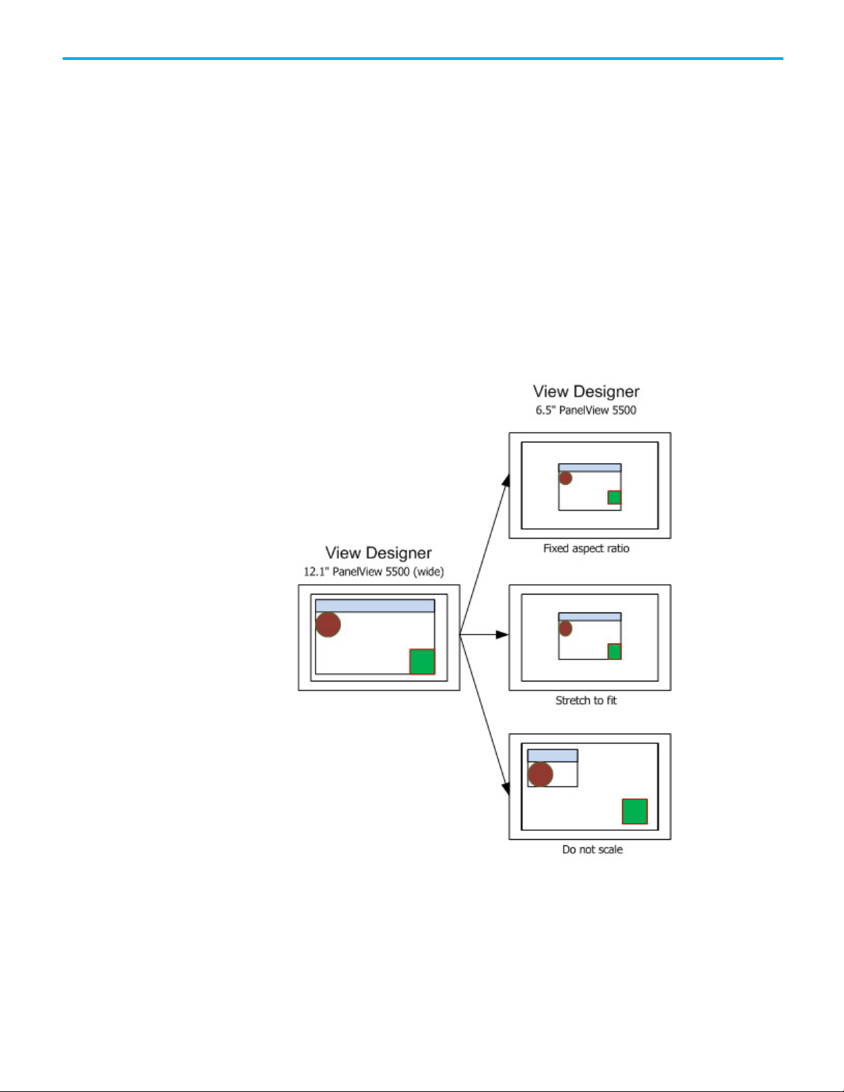
position properties of the graphic elements may have changed. The
animation values in a controller may need to be updated to reflect the
new size and position coordinates.
• Raster images
Bitmap or raster images store as a series of tiny dots called pixels.
When adding a raster image to a View Designer screen, the image
Height and Width property values in the Properties tab match the
pixel size of the image. Raster images may appear unclear because
View Designer scales the bitmap image to match the physical size of
the image as it appears on the HMI device screen. Images appear sharp
on the HMI device screen.
• Graphic elements
The corner radius and the border width of graphic elements do not
resize.
Chapter 3 Select an HMI device
Rockwell Automation Publication 9324-UM001D-EN-D - September 2020 65
Page 66

Chapter 3 Select an HMI device
See also
Application tab on page 59
Change the target HMI device for a project and select a Screen Scaling
option on page 61
Screen scaling overview on page 63
66 Rockwell Automation Publication 9324-UM001D-EN-D - September 2020
Page 67

Scaling examples
Chapter 3 Select an HMI device
Scaling options under Screen Scaling on the Application tab include:
Scale with fixed Aspect ratio
Screen examples represent the View Designer screen (canvas).
Stretch to fit
Rockwell Automation Publication 9324-UM001D-EN-D - September 2020 67
Screen examples represent the View Designer screen (canvas).
Page 68

Chapter 3 Select an HMI device
Runtime application scaling
Do not scale
See also
on different HMI devices
Change the target HMI device for a project and select a Screen Scaling
option on page 61
When downloading a project to a different HMI device, screens automatically
scale on the HMI device to fit based on the scaling option for the project. This
does not affect the project contents in View Designer. The scaling option is
appears on the Application tab of the Project Properties dialog box.
Downloading a project to an HMI device with a different DPI setting affects
the display of screens:
• Content placement
Screens appear in the center of the new HMI device. Any extra space
required for Scale with fixed aspect ratio or Do not scale options
appears equally on either side or above and below the screen. If the
new HMI screen is smaller than the original screen, the Do not scale
option is overridden to Scale with fixed aspect ratio to ensure screen
content is not clipped.
• Text
68 Rockwell Automation Publication 9324-UM001D-EN-D - September 2020
Text appears at the point size for the targeted HMI device. If the actual
HMI device differs, the text stretches to fit the new area based on the
scale mode selected. If the actual HMI device has a different aspect
ratio and the scale mode selected is Stretch to fit, the aspect ratio of
the text stretches or compresses to fill the new area.
Page 69

• System Banner
The System Banner is always as wide as the screen. The height of the
System Banner depends on the selected scaling option.
• Popups
Popups and their contents remain the same physical size as on the
original screen unless they do not fit the screens on the new HMI
device. In this case, the popups and their contents reduce to fit the new
screen area while maintaining a fixed aspect ratio. This is regardless of
the Screen Scaling option selected. After the screens convert, the
relative space that the popups cover on the new screens is different
from the original screens.
• Bindings to size and position properties
Downloading a project to a different HMI device does not affect
bindings to size and position properties of graphic elements. Update
animation values in the controllers as necessary to match the new size
and position values.
• Raster images
Chapter 3 Select an HMI device
Bitmap or raster images store as a series of tiny dots called pixels.
When adding a raster image to a View Designer screen, the image
Height and Width property values in the Properties tab match the
pixel size of the image. Raster images may appear unclear because
View Designer scales the bitmap image to match the physical size of
the image as it appears on the HMI device screen. Images appear sharp
on the HMI device screen.
Loading a raster image on an HMI device that is different from the
HMI device for the project results in the image appearing unclear
Rockwell Automation Publication 9324-UM001D-EN-D - September 2020 69
Page 70

Chapter 3 Select an HMI device
compared to the original. Add ore remove pixels to match the new
image size. The image size varies from with HMI device screen size.
70 Rockwell Automation Publication 9324-UM001D-EN-D - September 2020
Page 71

7-inch with
keypad
10-inch with
keypad
Screen (DPI)
123
123
133
103
96
96
Screen, W x H (mm)
132 x 99
132 x 99
152.5 x 91.5
196 x 118
211 x 158
211 x 158
15-inch with
Screen (DPI)
125
86
86
86
Screen, W x H (mm)
262.6 x 164.7
305.6 x 229.6
305.6 x 229.6
377.0 x 301.8
HMI device
Screen, W x H (mm)
115.2 x 86.4
152.5 x 91.5
196 x 118
211 x 158
262.6 x 164.7
PanelView 5000 HMI device
Chapter 3 Select an HMI device
See also
Project Properties dialog box on page 59
Screen scaling overview on page 63
Download a runtime application to a different HMI device on page 887
Dimensions and DPI for the PanelView 5510 HMI device include:
dimensions and DPI
HMI device
Screen diagonal (in) 6.5 6.5 7 9 10.4 10.4
Catalog number 2715P-T7CD 2715P-B7CD 2715P-T7WD 2715P-T9WD 2715P-T10CD 2715P-B10CD
Screen size (px) 640 x 480 640 x 480 800 X 480 800 x 480 800 x 600 800 x 600
7-inch
7-inch wide 9-inch wide 10-inch
Screen, W x H (in) 5.20 x 3.90 5.20 x 3.90 6 x 3.6 7.76 x 4.65 8.31 x 6.22 8.31 x 6.22
HMI device
Screen diagonal (in) 12.1 15 15 19
Catalog number 2715P-T12WD 2715PT-T15CD 2715P-B15CD 2715P-T19CD
Screen size (px) 1280 x 800 1024 x 768 1024 x 768 1280 x 1024
Screen, W x H (in) 10.34 x 6.48 12.03 x 9.04 12.03 x 9.04 14.84 x 11.88
12-inch wide 15-inch
keypad
19-inch
Dimensions and DPI for the PanelView 5310 HMI device include:
Screen diagonal (in) 5.7 7 9 10.4 12.1
Catalog number 2713P-T6CD1 2713P-T7WD1 2713P-T9WD1 2713P-T10CD1 2713P-T12WD1
Screen size (px) 640 x 480 800 X 480 800 x 480 800 x 600 1280 x 800
Screen (DPI) 142 133 103 96 125
6-inch 7-inch wide 9-inch wide 10-inch 12-inch wide
Screen, W x H (in) 4.5 x 3.4 6 x 3.6 7.76 x 4.65 8.31 x 6.22 10.34 x 6.48
Rockwell Automation Publication 9324-UM001D-EN-D - September 2020 71
Page 72

Chapter 3 Select an HMI device
Screen and content
measurements and display
See also
Application tab on page 59
Select a target HMI device for a new project on page 57
Screen and content measurements and display on page 72
View Designer is a WYSIWYG editor. Text and graphics on the screen in View
Designer closely resemble what appears on the target HMI device. Screens
and their content are measured and displayed in ways that ensure a project
can appear on different HMI devices.
Project screens
Project screens are measured by:
• Pixel dimension. Pixel dimension is the number of pixels wide and high
for a screen. For example, the 7" PanelView device is 640 wide x 480
pixels high. The density of these pixels is known as DPI (Dots Per Inch).
DPI is the number of pixels in a linear inch.
Screen resolution is also expressed in DPI. For example, the resolution
of the 7" PanelView device is 123 DPI.
• Physical size. The physical size of an HMI device screen is usually
specified as a diagonal measurement, such as from the lower left
corner to the upper right corner. For example, the physical size of the
7" PanelView device is 6.5".
The HMI device screen can also be measured by the width and height
measurements that are more important for motion animation. For
example, the 7" PanelView device is 5.20" wide x 3.90" high.
The proportional relationship between the width and height of a
screen is called aspect ratio.
The screens in View Designer measure the same as the screens of the
configured HMI device. This assumes that Windows is calibrated to the DPI of
the monitor on which View Designer is running. For example, the 7"
PanelView device is 640 x 480 pixels. To show the screens sized in View
Designer with Windows set to 96 DPI, the screens are scaled down to 500 x 375
pixels to represent the 5.20" x 3.90" size.
72 Rockwell Automation Publication 9324-UM001D-EN-D - September 2020
Page 73

Chapter 3 Select an HMI device
Text
Text size is typically measured in points, where a point is 1/72 of an inch. This
defines the height of the text, but not its width. This means that text width
varies slightly on different devices depending on the DPI of the device.
To prevent text from being distorted on screens of varying DPI, View
Designer draws the text at the DPI of the target HMI device and sets the width
and height based on the number of pixels the text used. Therefore, the X, Y,
Width, and Height property values in the Properties window are shown in the
pixel size they will be drawn on the configured HMI device. The text,
including its border, is scaled to the physical size it is on the HMI device.
Seeing and measuring the actual size maintains minimum touch areas. This
assumes that Windows is calibrated to the DPI of the monitor on which View
Designer is running.
Screen content
Screen content is sized to match the size of the font, so that when a screen is
viewed at 100%, the text and elements are the same size as they appear on the
HMI device.
Changing the HMI device for a project, and selecting Do Not Scale as a scaling
option causes the size and position properties to change to the pixels
necessary to maintain the same size. Text width may also change when the
DPI changes, so the font point size might also change to keep the text from
being clipped.
Changing the HMI device for a project, and selecting a scale mode other than
Do Not Scale also changes the size and position properties, including font
size. However, this is a relative change, not a physical change. The screen
elements take up the same percent of screen space on the new screen as they
did on the old screen, but they are now a different physical size and pixel size.
The spacing around content within a graphic element may differ on View
Designer screens that are targeted to different HMI devices. This is due to the
different HMI devices having different DPI values. However, text wrapping
for content within a graphic element is usually the same from View Designer
to an HMI device.
Rockwell Automation Publication 9324-UM001D-EN-D - September 2020 73
Page 74

Chapter 3 Select an HMI device
Raster images look unclear
in View Designer
See also
Select a target HMI device for a new project on page 57
Change the target HMI device for a project and select a Screen Scaling
option on page 61
PanelView 5000 HMI device dimensions and DPI on page 71
Screen scaling overview on page 63
Raster images, such as .bmp, .tif, .jpg, or .png files, are comprised of a grid of
pixels, or a bitmap. Scaling elements in View Designer to match the DPI of
the HMI device so that fonts look correct on the HMI device can make raster
images look unclear in View Designer. This happens when the DPI of the
target HMI device is much larger than the DPI under which View Designer is
running.
The unclear or pixelated effect occurs because the size of all of the elements on
the screen are reduced to match the fewer number of pixels used to display
fonts on View Designer. The image may look unclear in View Designer, but it
displays correctly on the target HMI device. You can typically scale down
raster graphics with little loss of quality.
Copying and pasting an image between View Designer projects for different
size HMI devices maintains the physical size of the image. The image no
longer has the same number of pixels on the new HMI device as it had on the
original HMI device. Add the image to the new screen or manually resize the
image to correct the size on the new HMI device.
See also
Screen scaling overview on page 63
Screen and content measurements and display on page 72
PanelView 5000 HMI device dimensions and DPI on page 71
74 Rockwell Automation Publication 9324-UM001D-EN-D - September 2020
Page 75

IMPORTANT
of structure, or an element of an array.
Add a controller reference
Chapter 4
Add a controller reference
A controller reference is a connection to a Logix Designer project file (.acd)
from a View Designer project file (.vpd). The connection automatically
synchronizes data between a Logix Designer project file (.acd) and View
Designer project file (.vpd).
Add up to four controller references, and a recommended maximum of
50,000 tags in a Logix controller to a project. Use a maximum of one
controller for each PanelView 5310 project or a maximum of four controllers
for a PanelView 5510 project.
Tip: Every scalar, array element, and structure member is considered a separate tag.
Use the References tab on the Project Properties dialog box to add or change
a controller reference.
See also
Add a controller reference on page 75
Synchronization on page 80
References tab on page 77
A controller reference is a connection to a Logix Designer project file (.acd)
from a View Designer project file (.vpd). The connection automatically
synchronizes data between a Logix Designer project file (.acd) and View
Designer project file (.vpd). For PanelView 5510 HMI devices, View Designer
supports up to four controller references.
Adding a controller reference adds the controller reference to the next
available reference card on the References tab. Each controller reference has a
number in the reference card. This controller number appears when browsing
for HMI device controller tags in the Tag Browser.
Rockwell Automation Publication 9324-UM001D-EN-D - September 2020 75
Select a controller only from an Ethernet network. Logix controllers and project files
must be version 27 or later.
Tip: For projects with a PanelView 5000 HMI device, the recommended number of tags across all
four Logix controllers is 200,000. A tag is a scalar tag. Scalar tags are BOOL, DINT, REAL, a member
Page 76

Chapter 4 Add a controller reference
To add a controller reference
1. On the Project Properties dialog box, select the References tab.
2. In the Controller[#] Reference Name box, type a unique name for the
controller reference. Name the controller reference a different name
than the project.
Tips:
• Add up to four controller references for projects configured with a PanelView 5510 HMI
device.
• Entering a controller reference name or selecting Add controller reference adds
an additional controller reference card for projects configured with a PanelView 5510
HMI device.
• Added controller references appear after the last controller reference card. After
saving controller references, reference cards appear in order by controller reference
number that appears in the Controller[#] Reference Name box.
• Adding the maximum number of controller references for an HMI device makes Add
controller reference unavailable.
• Controller References each contain an index number. When controllers replicate at the
same time, the controller with the lowest index number replicates before the other
controllers in queue. The controller with the lowest index number in queue has the
highest priority.
• The combined number of PanelView 5000 HMI devices and Logix controllers that can
communicate with each other through a 1756-EN2T or 1756-EN3T Ethernet module is
eight or fewer.
3. Type the path of the file or select a Logix Designer project file (.acd) by
selecting Browse next to the Logix Project File box.
Tip: The project file (.acd) for each referenced controller must be Logix Designer version 27
or later.
4. Set the path from the HMI device to the controller:
a. Type the IP address of the controller. To browse for the controller, after
the HMI to Controller Path box, select Browse and select the
controller running the selected Logix Designer project file (.acd).
b. In the Slot box, select the slot number of the controller to reference.
After browsing to the controller in the previous step, the slot
number appears automatically.
5. Set the path from the View 5000 Emulator to the controller:
a. After the Emulator to Controller Path box, select Browse and
select the controller running the selected Logix Designer project file
(.acd).
76 Rockwell Automation Publication 9324-UM001D-EN-D - September 2020
Page 77

Chapter 4 Add a controller reference
b. (optional) If the controller is previously viewed, select the Select
Controller Path list and select the controller from an Ethernet
network or virtual backplane running Logix Emulator.
Tips:
• The Select Controller Path list contains up to the last five recently viewed controller
paths. If there are no previously viewed paths, the list does not appear.
• Setting the Emulator to Controller path to the same path for multiple controller
references displays duplicate alarms in the Alarm Summary and the Alarm Manager. Each
alarm in the controller displays for each controller reference that has the same Emulator
to Controller path.
6. Select Apply to save changes and keep the Project Properties dialog
box open, or select OK to save changes and close the dialog box.
Tip: When browsing for a controller, the OK button is available when selecting a View
Designer-compatible device.
See also
Project Properties dialog box on page 59
References tab
References tab on page 77
Select a target HMI device for a new project on page 57
Remove a controller reference on page 79
How do I open the References tab?
1. Click VIEW > Project Explorer.
2. Right-click the project name.
3. Select Project Properties.
4. Click the References tab.
Use the References tab to add controller references to the project. A controller
reference is a connection to a Logix Designer project file (.acd) from a View
Designer project file (.vpd). Add up to four controller references for a
PanelView 5510 HMI device. The connection automatically synchronizes data
between a Logix Designer project file (.acd) and View Designer project file
(.vpd).
See also
Project Properties dialog box on page 59
Synchronization on page 80
Add a controller reference on page 75
Remove a controller reference on page 79
Rockwell Automation Publication 9324-UM001D-EN-D - September 2020 77
Page 78

Chapter 4 Add a controller reference
Browse for Controller
How do I open the Browse for Controller window?
window
Copy a controller reference
In the References tab of the Project Properties dialog box, or on the
Controller References page of the Download wizard, click Browse next
to the Slot box.
The Browse for Controller window is a network browser that displays active
network connections and devices in tree form.
Use the Browse for Controller window to select a controller to reference for
the project.
See also
Add a controller reference on page 75
Remove a controller from the network tree on page 80
Copy a controller reference within a View Designer project or from one View
Designer project to another. This eliminates the need to manually enter the
information in a project. Copy individual items from a controller reference or
the entire controller reference. Paste controller references that are of the same
version of Logix Designer.
Prerequisites
• Open the source View Designer project containing the content to copy.
• If pasting content into another project, start an instance of View
Designer and open the target project. Open no more than three
instances of View Designer at one time.
To copy a controller reference
1. In the source project, select Project > Project Properties and select the
References tab.
2. Right-click the controller reference and select Copy.
Tip: To copy a single item from a controller reference card, select the controller reference,
select the item to copy, and then right-click and select Copy.
3. In each target project:
a. Select Project > Project Properties and select the References tab.
b. Right-click the new controller reference card and select Paste.
Pasting assigns the next available controller reference number.
c. Select Apply to save changes and remain on the Project Properties
dialog box, or select OK to save changes and close the Project
Properties dialog box.
78 Rockwell Automation Publication 9324-UM001D-EN-D - September 2020
Page 79

references from the References tab removes the errors.
Remove a controller
Tips:
• Pasted controller references appear after the last controller reference card. Each
controller reference card has a controller reference number that identifies the position
on the References tab and the name of the referenced controller. When reopening the
References tab, reference cards appear in order by controller reference number that
appears in the Controller[#] Reference Name box.
• After saving controller references, reference cards appear in order by controller
reference number.
• For PanelView 5310 HMI devices, View Designer does not support pasting a controller
reference in a project that already contains a controller reference.
• For PanelView 5510 HMI devices, paste up to four controller references in a project.
• For multiple controllers and their tags to appear in the Tag Browser for a PanelView
5510 HMI device, the project file (.acd) for each referenced controller requires the
same version of Logix Designer.
• View Designer does not support pasting a number of controller references that
exceeds the total allowed for an HMI device. A prompt appears to paste the copied
controller references that do not exceed the maximum for the HMI device.
• The maximum number of controller references appears at the top of the References
tab and on the Usage & Capacity tab. Deleting the required number of controller
Chapter 4 Add a controller reference
reference
See also
Project Properties dialog box on page 59
References tab on page 77
Add a controller reference on page 75
Remove a controller reference on page 79
Reuse content on page 147
Removing a controller reference disconnects the View Designer project from
the Logix Designer project file (.acd). Tags and data types for the referenced
controller no longer appear in the Tag Browser or Data Type Browser.
To remove a controller reference
1. On the Project Properties dialog box, select the References tab.
2. To the right of the controller reference, select Remove controller
reference . The reference no longer appears.
Tips:
• Removing a controller reference adjusts the placement of any subsequent reference
cards. After saving controller references, reference cards appear in order by controller
reference number that appears in the Controller[#] Reference Name box.
• In the Controllers popup on the HMI device, any unused controller reference has a tab
named Not configured.
Rockwell Automation Publication 9324-UM001D-EN-D - September 2020 79
Page 80

Chapter 4 Add a controller reference
Remove a controller from
Synchronization
the network tree
3. Select Apply to save changes and remain on the Project Properties
dialog box, or select OK to save changes and close the Project
Properties dialog box.
See also
Project Properties dialog box on page 59
References tab on page 77
Remove a controller from the network tree in the Browse for Controller
window to display only the controllers that are relevant to the project.
To remove a controller from the network tree
1. On the References tab of the Project Properties dialog box, or on the
Controller References page of the Download wizard, select Browse
next to the Slot box.
2. In the Browse for Controller window, right-click the controller and
select Remove.
See also
Browse for Controller window on page 78
Add a controller reference on page 75
Studio 5000 automatically synchronizes data between a Logix Designer
project file (.acd) and a View Designer project file (.vpd). It also synchronizes
data between the runtime application on the HMI device and the controllers
connected to that HMI device. The synchronized data includes tags, data
types, program tags, and alarms. The synchronization service automatically
runs in the background every 15 seconds, enabling work to continue while the
data synchronizes.
See also
Synchronization between Logix Designer and View Designer on page
81
Tag browsing in a secured Logix Designer project file on page 82
80 Rockwell Automation Publication 9324-UM001D-EN-D - September 2020
Synchronization: Controller state indicator icons on page 81
Page 81

Icon
Description
Synchronization between
Logix Designer and View
Synchronization: Controller
Designer
When creating an HMI project in View Designer, use the synchronized data
to bind to graphic elements, screens, or expressions.
Chapter 4 Add a controller reference
In View Designer
Synchronization state indicator icons appear next to a controller on
the References tab, and on the Tag Browser window to indicate the
state of the controller. The state indicators do not appear if there is no
new data to synchronize.
• When adding a new controller reference, content is synchronized
between the Logix Designer project file (.acd) for that controller and
the View Designer project file (.vpd).
• When synchronization is in progress, downloading an HMI project to
the HMI device is not supported. As a best practice, Rockwell
Automation recommends saving the HMI project after synchronization
is complete.
• When changing a controller reference, select OK on the References tab
to synchronize content between the newly referenced Logix Designer
project file (.acd) for that controller and the View Designer project file
(.vpd). If the Logix Designer project file (.acd) is not valid, the
synchronization service displays an error, synchronization does not
take place, and the HMI project references the previously synchronized
data from the last referenced Logix Designer project file (.acd).
• When deleting a controller reference, the previously synchronized data
from the Logix Designer project file (.acd) no longer appears in the
View Designer project file.
state indicator icons
In Logix Designer
When making a change in a Logix Designer project file (.acd), the
synchronization service detects the changes to a Logix Designer project file
(.acd). The synchronization service automatically synchronizes data between
the Logix Designer and View Designer project files.
See also
Synchronization between the runtime application and the controller
on page 82
Tag browsing in a secured Logix Designer project file on page 82
These are the controller state indicator icons:
A controller is synchronizing.
Rockwell Automation Publication 9324-UM001D-EN-D - September 2020 81
Page 82
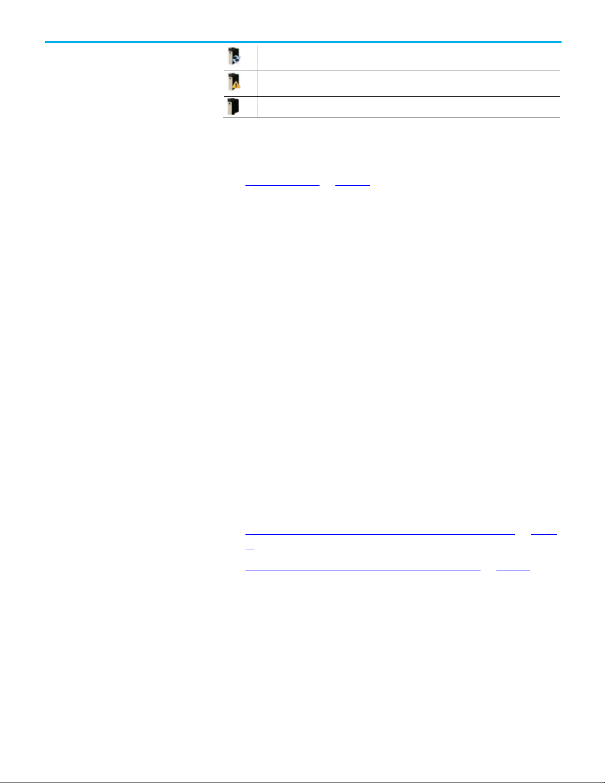
Chapter 4 Add a controller reference
mouse on the icon to display additional information.
version that is not supported. Hover your mouse on the icon to display additional information.
Synchronization between
Tag browsing in a secured
the runtime application and
the controller
The data in a controller is not synchronized. Controller data synchronizes automatically. Hover the
A synchronization error occurred. The Logix Designer project file (.acd) does not exist, or it is a
The controller is synchronized.
See also
Synchronization on page 80
When downloading the HMI project to the HMI device, the synchronization
service connects the runtime application to the controller referenced in the
HMI project. After the synchronization service connects to the controller, it
reads data from the controller to determine if it matches the data in the HMI
project. If the data does not match, the data in the HMI project automatically
synchronizes with the data in the controller.
When the runtime application runs on the HMI device, the synchronization
service checks if the Logix Designer file in the controller was updated. The
Logix Designer project file in the controller can be updated using the online
editing features in Logix Designer. If the project file was updated, the
synchronization service will automatically synchronize data between the
Logix Designer project file referenced in the runtime application and the
newly updated Logix Designer project file in the controller.
Logix Designer project file
Configure system tags to display information about the synchronization
status of the runtime application and the Logix5000 controller or use the
ControllersGeneral screen in the Predefined Screens folder.
See also
Synchronization between Logix Designer and View Designer on page
81
Tag browsing in a secured Logix Designer project file on page 82
Browsing for tags in a secured Logix Designer project file (.acd) from View
Designer is allowed only with security access to the .acd file.
The first logged-on user to open View Designer may prevent subsequent users
who log on and open View Designer from synchronizing .acd files in their
Documents folder while the first user is still logged on. To prevent this:
• Have the subsequent user synchronize with a file that both the
subsequent user and first user can access.
• Have the first user log off before the subsequent user logs on.
82 Rockwell Automation Publication 9324-UM001D-EN-D - September 2020
Page 83

View the default content of
If multiple users log on and log off of the same computer, and the first user to
start View Designer logs out, subsequent users will no longer be able to
synchronize .acd files or create or change references to them. To prevent this,
have only one user logged on to a multi-user computer at a time when
running View Designer.
Install Logix Designer to synchronize with an .acd file.
Install Logix Designer version 27 or version 28, or Studio 5000 Logix Designer
version 29 to add a reference to their respective .acd file. However, A View
Designer project (.vpd file) that already has an .acd file reference added and
synchronized stays synchronized without installing Logix Designer.
Chapter 4 Add a controller reference
See also
Synchronization between Logix Designer and View Designer on page
81
Synchronization between the runtime application and the controller
on page 82
a project
Project Explorer
View Designer provides default content to use to build and organize a project.
The Project Explorer displays the contents of a View Designer project in tree
form. The root-level project folder contains the project name and default
folders -- Navigation Menu, User-Defined Screens, and Predefined Screens.
See also
Project Explorer on page 83
Predefined Screens folder on page 85
What is the System Banner? on page 86
What is the Settings screen? on page 86
What is the Alarm Summary? on page 88
How do I open the Project Explorer?
On the Menu bar, click VIEW > Project Explorer.
Rockwell Automation Publication 9324-UM001D-EN-D - September 2020 83
The Project Explorer displays the contents of a View Designer project in tree
form. The root-level project folder contains the project name and default
folders. These folders contain the items of the project, including default
content. Project items include:
Page 84

Chapter 4 Add a controller reference
Default Folder
Screens
Shortcuts
Popups
Folders
Default Project
Popups
Add-On
Images
Sample
Documents
Events
Navigation Menu
User-Defined
Screens
Predefined Screens
Assets
Data Logging
Project Events
Screens and
Graphics
rates
The content and its order in the Navigation Menu folder are displayed as
menu items in the Navigation menu on the HMI device. The shortcuts in the
Navigation Menu folder are based on user-defined screens or the Settings,
Alarm Summary, and Alarm Manager predefined screens.
Use the Project Explorer to:
• Browse and organize the contents of a project.
• Add screens, shortcuts, popups, and folders to a project.
• Open, rename, and delete screens, shortcuts, popups, and folders.
• Create navigation for the user on the HMI device.
• Create an Add-On Graphic or image to add to a screen or popup
• Create a data log with sample rates to add to a screen or popup
• Display the properties of a project, such as controller references and
the target HMI device.
• Verify a project.
• Rename a project.
• Add a PDF document
• Create project events
• Copy and paste single and multiple objects.
Right-click an item in the Project Explorer to see a list of actions to perform.
84 Rockwell Automation Publication 9324-UM001D-EN-D - September 2020
Page 85

Predefined Screens folder
Chapter 4 Add a controller reference
See also
Create a screen on page 92
Create a shortcut to an existing screen on page 105
Create a popup on page 116
Open a screen on page 93
Specify a Home screen on page 303
The Predefined Screens folder in the Project Explorer contains default
screens, popups, and a Banner item for each project. The contents of the
Predefined Screens folder includes:
• Banner. By default, this item appears at the top of each project screen.
It displays date and time, active and unacknowledged alarm indicators,
controller diagnostic, and network diagnostic information. It also
provides buttons to navigate to the Alarm Summary, log on and log off
the project, move backward and forward through navigation history,
and display the Navigation menu at the bottom of the HMI device.
• Settings. This screen provides a menu to configure settings for the HMI
device. By default, access the Settings screen through the Navigation
menu on the HMI device. The options on the Settings screen open the
popups listed under the screen in the Predefined Screens folder. These
popups perform tasks to configure HMI device settings.
• AlarmSummary. This screen displays the Alarm Summary, a list of
alarms that are in interestingstates or that require attention. For
example, the Alarm Summary lists alarms that are In Alarm and
Unacknowledged. By default, access the AlarmSummary screen
through the System Banner or the Navigation menu on the HMI
device.
• AlarmManager. This screen displays the Alarm Manager, a list of all
alarms regardless of their state. Alarms listed in the Alarm Manager
include all of the conditions for an alarm. By default, access the
AlarmManager screen through the Navigation menu or the Alarm
Summary on the HMI device.
• AlarmHistory. This screen displays the Alarm History, a list of all alarm
state changes. By default, access the AlarmHistory screen through the
Navigation Menu.
Rockwell Automation Publication 9324-UM001D-EN-D - September 2020 85
Page 86

Chapter 4 Add a controller reference
What is the System Banner?
What is the Settings
See also
What is the Settings screen? on page 86
What is the Alarm Manager? on page 88
What is the Alarm Summary? on page 88
What is the System Banner? on page 86
The System Banner appears at the top of each screen configured to show the
System Banner, and each shortcut to which you have access. The System
Banner contains a default set of items. Security access to the System Banner
cannot be set for a particular role. You can remove the System Banner from a
screen or shortcut through the Properties window for the selected screen or
shortcut.
You can change the height of the System Banner, but not the width. The
System Banner is always as wide as the screen.
If you do not scale screens and change the HMI device type for your project,
this affects the System Banner. For example, blank space appears to the right
of the System Banner when you configure the project for larger HMI device
screens. Space to the right of the System Banner is removed when you
configure the project for smaller HMI device screens. When you do not scale
screens and change project settings to a smaller HMI device, elements may
appear clipped at the right end of the System Banner on the HMI device.
See also
Open the System Banner on page 130
Add a graphic element to the System Banner on page 132
Remove a graphic element from the System Banner on page 134
Remove the System Banner from a screen on page 134
System Banner contents on page 137
screen?
86 Rockwell Automation Publication 9324-UM001D-EN-D - September 2020
Use the Settings screen on the HMI device to view and change HMI device
and system-wide settings. The Settings screen opens popups that appear in
the Predefined Screens folder of the Project Explorer. View Designer does
not support moving the popups into the User-Defined Screens folder. Create
events to open these popups from other screens and graphic elements in a
project. On the HMI device, use the Settings screen to select an option to open
a popup and perform the associated tasks.
Page 87
Option:
Popup:
Tasks:
• Specify DNS addresses
• Specify link duplex
NetworkDiagnostic tab
• View network diagnostics
touch
• View diagnostic information
device
Set the time zone for the HMI device
information
Media
an SD Card inserted into the HMI device.
disable the remote access to the HMI device.
Email
Email
• Configure the SMTP client to send emails.
Chapter 4 Add a controller reference
Network
Display Display • Adjust the HMI device screen brightness
HMI Device
Data Export Data Export • Export the alarm history or data logs to
NetworkIPSettings tab • Specify Internet protocol settings
• Specify IP addresses
NetworkLinkSettings tab • Enable Ethernet links
• Set link speed
• Turn on the screen saver
• Set the brightness and delay for the screen
saver
Calibrate the screen to respond accurately to
•
HMIDevice • Specify if project downloads and firmware
updates are allowed
• Change the name of the HMI device
• View catalog and firmware numbers
HMIDevice_RebootConfirm • Reboot the HMI device
removable media
Troubleshooting Troubleshooting • Import a troubleshooting profile
• Export a troubleshooting log
• Turn off troubleshooting and reboot the HMI
Date and Time DateAndTime • Set the date and time for the HMI device
•
Controllers
Download from
VNC VNC • Configure remote access rights to an HMI
ControllersGeneral tab • View controller reference and status
ControllersDiagnostic tab • View controller diagnostics
Load Application • Load a .vpdr file from an HMI storage device or
device as either Full-Access or View-Only, or
See also
Predefined Screens folder on page 85
What is the System Banner? on page 86
Rockwell Automation Publication 9324-UM001D-EN-D - September 2020 87
What is the Alarm Summary? on page 88
What is the Alarm Manager? on page 88
Page 88

Chapter 4 Add a controller reference
• The 5380, 5480 and 5580 Logix families of controllers support tag-based alarms.
What is the Alarm
What is the Alarm Manager?
Summary?
The Alarm Summary lists alarms that are In Alarm or Unacknowledged. The
Alarm Summary automatically subscribes to all alarms from the controller
references specified in the project properties. It displays one alarm condition
per row. Use the Alarm Summary to monitor and interact with alarms. Add
or remove columns to show different data for alarms in the Alarm Summary
table. The 5380, 5480 and 5580 Logix families of controllers support tag-based
alarms.
Use the Alarm Summary on an HMI device to:
• Acknowledge alarms.
• Disable alarms.
• Shelve alarms.
• Sort alarms.
• Filter alarms.
• Pause alarms.
• Reset digital alarms.
• View alarm details.
See also
Alarm Summary contents for a large HMI device screen on page 330
Alarm Summary contents for a medium HMI device screen on page
328
Alarm Summary table columns on page 331
Columns tab on page 333
Details pane for an Alarm Summary on page 333
The Alarm Manager lists all alarms configured in a system and their current
states. The Alarm Manager subscribes to alarms in the controllers. Every
alarm from the controllers is listed unless an alarm is removed from a
controller. Use the Alarm Manager table to monitor and interact with the
alarms on the HMI device.
Tips:
• For tag-based alarms, the Alarm Manager only displays alarms with Use and evaluate
alarm selected in Logix Designer.
By default, an AlarmManager screen is included in each project. Create a
user-defined Alarm Manager screen by adding an Alarm Manager graphic
element to a screen in View Designer.
88 Rockwell Automation Publication 9324-UM001D-EN-D - September 2020
Page 89

Chapter 4 Add a controller reference
Use the Alarm Manager to:
• View alarm names to identify the controller and tag of an alarm.
• Enable or disable alarms to take them in or out of service.
• Shelve and unshelve alarms and alarm conditions.
• Reset counts for alarms.
• Sort and filter alarms.
• View alarm errors.
• View individual conditions for an alarm.
• View details for a selected alarm or alarm condition.
See also
Alarms overview on page 313
Create an alarm screen on page 316
Alarm Manager contents for a large HMI device screen on page 343
Alarm Manager table columns on page 346
Rockwell Automation Publication 9324-UM001D-EN-D - September 2020 89
Page 90

Page 91

Work with screens
Screen tab
Chapter 5
Screens
Use a screen to contain content and create shortcuts that appear in the
application on the HMI device. After adding a screen to a project, build the
content and design the behavior to see on the HMI device. For PanelView 5510
and PanelView 5310 HMI devices, a project can contain a total of 100 screens,
including a maximum 50 popups.
Once the screen is created, add content to and configure the behavior of the
screen to provide interactivity on the HMI device.
See also
Screen tab on page 91
Create a screen on page 92
Open a screen on page 93
Change the background color of a screen on page 93
Delete a screen on page 98
How do I open the Screen tab?
The screen designated as the Home screen opens when a project opens. To
open a different screen for the project, in the Project Explorer, expand the
User-Defined Screens folder, and double-click the screen. Screen names are
preceded by a Screen icon .
The Screen tab is the drawing area used to create or edit the screens and
popups viewed on the HMI device. For PanelView 5510 and PanelView 5310
HMI devices, a project can contain a total of 100 screens, including a
maximum 50 popups.
Use the Screen tab to perform tasks:
Rockwell Automation Publication 9324-UM001D-EN-D - September 2020 91
• Create and change graphic elements.
• Cut, copy, paste, and delete graphic elements.
• Group, ungroup, or change the order of graphic elements.
• Align or distribute graphic elements horizontally or vertically.
• Lock a graphic element so it cannot be moved by the HMI designer.
Page 92

Chapter 5 Screens
Tip:
Create a screen
For example, to design a screen that depicts a bottling line, add graphic
elements representing bottles, conveyors, and other associated graphic
elements and text.
See also
Create a screen on page 92
Create a popup on page 116
Specify a Home screen on page 303
Rename a screen on page 96
Change the background color of a screen on page 93
A screen in View Designer contains the items to appear on the screen on the
HMI device. After adding a screen to a project, build the content and design
the behavior to see on the HMI device. For PanelView 5510 and PanelView 5310
HMI devices, a project can contain a total of 100 screens, including a
maximum 50 popups.
To create a screen:
• In the Project Explorer, right-click the User-Defined Screens folder and
click New Screen. A screen named Screen_002 or increment number is
added to the folder.
After adding the screen, create content for it by adding graphic elements.
See also
Add a graphic element to a screen on page 417
Screen tab on page 91
Popup tab on page 115
Project Explorer on page 83
92 Rockwell Automation Publication 9324-UM001D-EN-D - September 2020
Page 93

Open a screen
Change the background
Open a screen to display its contents.
Chapter 5 Screens
To open a screen:
1. In the Project Explorer, expand the User-Defined Screens or
Predefined Screens folder.
2. Double-click the screen. The screen opens on its own tab.
See also
Create a screen on page 92
Change the background color of a screen on page 93
Project Explorer on page 83
Screen tab on page 91
color of a screen
Change the background color of a screen to a different color, gradient color,
or custom color.
To change the background color of a screen:
1. In the Project Explorer, expand the User-Defined Screens or
Predefined Screens folder.
2. Select the screen, or double-click the screen to open it.
3. In the Properties window, select the Properties tab.
4. Expand the Appearance category.
5. In the FillColor box, select a color using one of these methods:
• Type the Hex value in the format #RRGGBB. R, G, and B are Hex
digits from 0 through F and represent the color channel values for
red, green, and blue. For example, #ffff00 produces yellow.
• Select the arrow or color swatch to open the Color Picker, and
select or create a color.
• In the Color Picker, create a color gradient.
The selected color appears in the Fill Color box.
Rockwell Automation Publication 9324-UM001D-EN-D - September 2020 93
Page 94

Chapter 5 Screens
Change the background
color of a popup
See also
Project Explorer on page 83
Create a screen on page 92
Color Picker overview on page 638
Create a color gradient on page 640
Bind a color property to a tag or expression on page 643
Change the background color of a popup to a different color, gradient color,
or custom color. Radial gradients are not supported for popup fill color.
To change the background color of a popup
1. In the Project Explorer, expand the User-Defined Screens folder.
2. Double-click the popup to open the popup.
3. In the Properties window, click the Properties tab.
4. Expand the Appearance category.
5. In the FillColor box, select a color using one of these methods:
• Type the Hex value in the format #RRGGBB. R, G, and B are Hex
digits from 0 through F and represent the color channel values for
red, green, and blue. For example, #ffff00 produces yellow.
• Select the arrow or color swatch to open the Color Picker, and
select or create a color.
See also
Create a popup on page 116
Change the opacity of a popup on page 121
Create a color gradient on page 640
Select a fill color on page 422
Create a custom color using the Color Picker on page 639
94 Rockwell Automation Publication 9324-UM001D-EN-D - September 2020
Page 95

Copy a screen
Chapter 5 Screens
Copy a screen to reuse it within or across View Designer projects. Paste a
screen into the same folder in the Project Explorer to create a copy of the
screen and append the name with an increment number. Paste screens from
the Predefined Screens folder only into the User-Defined Screens folder
within or across projects. Content copied to a project with a different HMI
screen size maintains its original size and position.
Prerequisites:
• Open the source View Designer project containing the content to copy.
• If the content is to be pasted into another project, for each project,
start an instance of View Designer and open the target project. It is
recommended to open no more than three instances of View Designer
at one time.
To copy a screen
1. In the source project, in the Project Explorer, right-click the screen
and select Copy.
Tip: To select multiple screens, hold Ctrl and select the items.
2. Right-click the target folder and select Paste. If the target folder
contains a screen with the same name, select one of two options:
• Select Replace to overwrite the existing screen.
• Select Keep Both to keep both screens. The name of the new screen
is appended with a number that increments with each copy.
Rockwell Automation Publication 9324-UM001D-EN-D - September 2020 95
Page 96

Chapter 5 Screens
children is also copied.
Rename a screen
Tips:
• Copying a screen that contains an instance of an Add-On Graphic to a different
project that does not contain an Add-On Graphic with the same name adds the
definition of the Add-On Graphic to the Assets > Add-On Graphics folder of the
Project Explorer and adds the Add-On Graphic to the Toolbox category indicated
for the Add-On Graphic.
• Copying a screen that contains an instance of an Add-On Graphic to a different
project that contains an Add-On Graphic with the same name provides three
options:
• Keep Both. Append the name of the copied Add-On Graphic definition with _001
or increment number. The definition appears in the folder and the Add-On
Graphic appears in the Toolbox.
• Replace. Replace the existing Add-On Graphic definition with the copied
definition. Any instances of the existing Add-On Graphic are updated with the
new definition of the Add-On Graphic.
• Cancel. Do not paste the copied Add-On Graphic definition into the project.
• If pasting a screen with an Add-On Graphic replaces an alias property in the
definition of an Add-On Graphic and that alias is linked in an instance, the alias
property shows in the Properties window of the instance, and the alias remains
linked to the value of the base property in the definition.
• If pasting a screen with an Add-On Graphic replaces an alias property in the
definition of an Add-On Graphic and that alias is unlinked in an instance, the alias
property shows in the Properties window of the instance, but the alias property
retains its value from the original Add-On Graphic definition. The value of the
alias property is not linked to the base property of the pasted Add-On Graphic
definition.
• Copying a screen that has an Add-On Graphic with an image that exists in both
the source and target projects displays a prompt to replace the image. Images
are copied to the Assets > Images folder of the Project Explorer.
• When copying a screen, any localized data associated with the screen and its
96 Rockwell Automation Publication 9324-UM001D-EN-D - September 2020
See also
Create a screen on page 92
Rename a screen on page 96
Delete a screen on page 98
Reuse content on page 147
Project Explorer on page 83
By default, each project contains a screen named Screen_001. This number
increments with each new screen created with the same name.
Rename a screen to make the name more meaningful. For example, give the
screen a name that reflects its purpose, content, or targeted use. Names
within a folder must be unique and are not case sensitive. For example,
Bottling_Line and bottling_line are considered identical names. Renaming
any screen in the Predefined Screens folder is not allowed.
Page 97

Restore the default content
of a predefined item
Chapter 5 Screens
To rename a screen:
1. In the Project Explorer, expand the User-Defined Screens folder.
2. Click the screen once to select the item.
3. Click the screen again and type the new name.
Tip: Right-clicking the name, selecting Rename, and entering a new name also renames the
screen.
See also
Change the background color of a screen on page 93
Delete a screen on page 98
Project Explorer on page 83
Screen tab on page 91
Restore the default content of a screen, popup, or Banner item in the
Predefined Screens folder of the Project Explorer to overwrite any changes
made to the item. For example, restore the content of the Banner item to have
the default content appear at the top of screens.
To restore the default content of a predefined item
1. With the revised item open, press CTRL+A to select all remaining
content in the item and press Delete.
2. Open another View Designer project and open the unchanged version
of the item.
3. With the unchanged item open, press CTRL+A to select all of the
default content.
4. Right-click a selected item and select Copy to copy the content to the
clipboard.
5. Right-click the empty revised item and select Paste. The default
content of the item is restored.
See also
Predefined Screens folder on page 85
What is the System Banner? on page 86
What is the Settings screen? on page 86
Rockwell Automation Publication 9324-UM001D-EN-D - September 2020 97
What is the Alarm Summary? on page 88
What is the Alarm Manager? on page 88
Page 98

Chapter 5 Screens
Delete a screen
Close a screen
Delete a screen to remove it from the project. Delete screens from the User-
Defined Screens folder in the Project Explorer. To delete a screen that is
referenced by shortcuts, first delete the shortcuts. Deleting a screen from the
Predefined Screens folder is not allowed. You cannot undelete a screen.
Prerequisites
• In the Navigation Menu folder, delete any shortcuts based on the
screen to delete.
To delete a screen
1. In the Project Explorer, expand the User-Defined Screens folder.
2. Right-click the screen, and select Delete. The screen is removed from
the Project Explorer.
See also
Create a screen on page 92
Change the background color of a screen on page 93
Project Explorer on page 83
Screen tab on page 91
Close a screen to close items in a project that no longer need to be open. For
example, close items that currently do not require viewing or editing.
To close a screen
• On the tab of the item, select Close .
See also
Close all screens on page 99
98 Rockwell Automation Publication 9324-UM001D-EN-D - September 2020
Change the background color of a screen on page 93
Project Explorer on page 83
Screen tab on page 91
Page 99

Close all screens
Restrict access to an item
Close all screens in a project simultaneously to not close each screen
individually. Closing all documents closes only screens. All other windows and
tabs remain open.
Chapter 5 Screens
To close all screens
1. Select Window > Close All Documents.
2. If prompted to save changes to the screens, select Yes to save changes,
or select No to not save changes.
See also
Screen tab on page 91
Close a screen on page 98
Delete a screen on page 98
Rename a screen on page 96
on the HMI device
Project Explorer on page 83
By default, all users on HMI devices have access to these items in the Project
Explorer:
• Shortcuts in the Navigation Menu folder.
• Screens and popups in the User-Defined Screens and Predefined
Screens folders. Navigate to these items on the HMI device by
triggering an event with a navigation command. Users who do not
have the Administrator role have read-only access to the Settings
screen and related popups in the Predefined Screens folder.
Change the access level for any item in the Project Explorer. Restrict access to
an item for any role except the Administrator role. The Administrator role
always has Inherit access, and the role inherits Full Access from the root
folder.
To restrict access to an item on the HMI device
1. In the Project Explorer, expand the folder that contains the item to
restrict access:
Rockwell Automation Publication 9324-UM001D-EN-D - September 2020 99
• To select a screen or popup, expand the User-Defined Screens
folder or the Predefined Screens folder.
• To select a shortcut, expand the Navigation Menu folder.
2. Select or double-click the item. The Properties window for the item
opens.
Page 100

Chapter 5 Screens
3. In the Properties window for the selected item, expand the Security
category.
4. After each role (Engineer, Maintenance, Operator, Restricted, and
Supervisor), select the access option for each role.
• Inherit. Grants the same access assigned to the parent folder.
• Full Access. Grants access to open and interacts with the item, and
shows the item in the Navigation menu on the HMI device.
• Read Only. Grants access to open the item, but denies interaction
with it. The item appears in the Navigation menu on the HMI
device. Users assigned to a role with read-only access can still
interact with the Navigation menu and alarm tables. For example, a
user with read-only access to an alarm table can still perform read
operations, such as viewing alarms and details, selecting alarms and
conditions, filtering alarms, and pausing alarms. The user cannot
perform write commands that change the state of an alarm.
• No Access. Denies access to open or interact with the item. The
item does not appear in the Navigation menu on the HMI device.
5. To set individual role access to a shortcut, independent of the access to
the screen on which the shortcut is based:
a. Select the shortcut.
b. In the Properties window of the selected shortcut, clear the
UseScreenSecurity check box.
c. Select the access level for each role.
Do not base the security for a shortcut on its defining screen if the
user has access to some shortcuts of a screen but should not have
access to a particular shortcut.
See also
Restrict access to the HMI device on page 761
Restrict access to a graphic element on page 761
Project Explorer on page 83
Properties tab on page 294
Security overview on page 765
100 Rockwell Automation Publication 9324-UM001D-EN-D - September 2020
 Loading...