

Page 1

PowerFlex 755/755T
Integrated Safety Functions
Option Module
Catalog Number 20-750-S4
User Manual
Original Instructions
Page 2
PowerFlex 755/755T Integrated Safety Functions Option Module User Manual
Important User Information
Read this document and the documents listed in the additional resources section about installation, configuration, and
operation of this equipment before you install, configure, operate, or maintain this product. Users are required to familiarize
themselves with installation and wiring instructions in addition to requirements of all applicable codes, laws, and standards.
Activities including installation, adjustments, putting into service, use, assembly, disassembly, and maintenance are required to
be carried out by suitably trained personnel in accordance with applicable code of practice.
If this equipment is used in a manner not specified by the manufacturer, the protection provided by the equipment may be
impaired.
In no event will Rockwell Automation, Inc. be responsible or liable for indirect or consequential damages resulting from the use
or application of this equipment.
The examples and diagrams in this manual are included solely for illustrative purposes. Because of the many variables and
requirements associated with any particular installation, Rockwell Automation, Inc. cannot assume responsibility or liability for
actual use based on the examples and diagrams.
No patent liability is assumed by Rockwell Automation, Inc. with respect to use of information, circuits, equipment, or software
described in this manual.
Reproduction of the contents of this manual, in whole or in part, without written permission of Rockwell Automation, Inc., is
prohibited.
Throughout this manual, when necessary, we use notes to make you aware of safety considerations.
WA RN I NG : Identifies information about practices or circumstances that can cause an explosion in a hazardous environment,
which may lead to personal injury or death, property damage, or economic loss.
ATTENTION: Identifies information about practices or circumstances that can lead to personal injury or death, property
damage, or economic loss. Attentions help you identify a hazard, avoid a hazard, and recognize the consequence.
IMPORTANT Identifies information that is critical for successful application and understanding of the product.
Labels may also be on or inside the equipment to provide specific precautions.
SHOCK HAZARD: Labels may be on or inside the equipment, for example, a drive or motor, to alert people that dangerous
voltage may be present.
BURN HAZARD: Labels may be on or inside the equipment, for example, a drive or motor, to alert people that surfaces may
reach dangerous temperatures.
ARC FLASH HAZARD: Labels may be on or inside the equipment, for example, a motor control center, to alert people to potential
Arc Flash. Arc Flash will cause severe injury or death. Wear proper Personal Protective Equipment (PPE). Follow ALL Regulatory
requirements for safe work practices and for Personal Protective Equipment (PPE).
2 Rockwell Automation Publication 750-UM005C-EN-P - February 2021
Page 3

About Safe Stop and Safe
Monitor Functions
Table of Contents
Preface
Summary of Changes . . . . . . . . . . . . . . . . . . . . . . . . . . . . . . . . . . . . . . . . . . . 9
Conventions. . . . . . . . . . . . . . . . . . . . . . . . . . . . . . . . . . . . . . . . . . . . . . . . . . . 9
Terminology. . . . . . . . . . . . . . . . . . . . . . . . . . . . . . . . . . . . . . . . . . . . . . . . . . 10
Product Firmware and Release Notes . . . . . . . . . . . . . . . . . . . . . . . . . . . 12
Additional Resources . . . . . . . . . . . . . . . . . . . . . . . . . . . . . . . . . . . . . . . . . . 13
Chapter 1
What Is the Integrated Safety Functions Option Module? . . . . . . . . 15
Compatible Drives . . . . . . . . . . . . . . . . . . . . . . . . . . . . . . . . . . . . . . . . . . . . 17
Compatible Safety Controllers . . . . . . . . . . . . . . . . . . . . . . . . . . . . . . . . . 17
Safety Application Requirements . . . . . . . . . . . . . . . . . . . . . . . . . . . . . . . 18
Safety Certification. . . . . . . . . . . . . . . . . . . . . . . . . . . . . . . . . . . . . . . . . . . . 18
Important Safety Considerations . . . . . . . . . . . . . . . . . . . . . . . . . . . 18
Stop Category Definitions . . . . . . . . . . . . . . . . . . . . . . . . . . . . . . . . . 19
Performance Level and Safety Integrity Level (SIL) CL3 . . . . . . 19
Proof Tests . . . . . . . . . . . . . . . . . . . . . . . . . . . . . . . . . . . . . . . . . . . . . . . . . . . 20
PFD and PFH Definitions . . . . . . . . . . . . . . . . . . . . . . . . . . . . . . . . . . . . . 20
PFD and PFH Data . . . . . . . . . . . . . . . . . . . . . . . . . . . . . . . . . . . . . . . . . . . 21
Safety Data for Safe Torque Off . . . . . . . . . . . . . . . . . . . . . . . . . . . . 21
Safety Data for Safe Feedback. . . . . . . . . . . . . . . . . . . . . . . . . . . . . . . 21
Safety Data for Safety I/O. . . . . . . . . . . . . . . . . . . . . . . . . . . . . . . . . . 22
Spurious Trip Rate . . . . . . . . . . . . . . . . . . . . . . . . . . . . . . . . . . . . . . . . 23
Safety Reaction Time. . . . . . . . . . . . . . . . . . . . . . . . . . . . . . . . . . . . . . . . . . 23
Considerations for Safety Ratings. . . . . . . . . . . . . . . . . . . . . . . . . . . . . . . 24
Encoder Considerations . . . . . . . . . . . . . . . . . . . . . . . . . . . . . . . . . . . . . . . 24
Supported Encoders . . . . . . . . . . . . . . . . . . . . . . . . . . . . . . . . . . . . . . . 24
Encoder Diagnostics . . . . . . . . . . . . . . . . . . . . . . . . . . . . . . . . . . . . . . . 24
General Encoder Diagnostics . . . . . . . . . . . . . . . . . . . . . . . . . . . . . . . 25
Digital AqB Diagnostics . . . . . . . . . . . . . . . . . . . . . . . . . . . . . . . . . . . 27
Sine/Cosine and Hiperface Diagnostics . . . . . . . . . . . . . . . . . . . . . 27
Contact Information If Safety Option Failure Occurs . . . . . . . . . . . . 28
Chapter 2
Installation Remove Power to the System. . . . . . . . . . . . . . . . . . . . . . . . . . . . . . . . . . . 30
Access the Control Pod . . . . . . . . . . . . . . . . . . . . . . . . . . . . . . . . . . . . . . . . 30
Set the SAFETY and Hardware ENABLE Jumpers . . . . . . . . . . . . . . 31
Install the Safety Option Module . . . . . . . . . . . . . . . . . . . . . . . . . . . . . . . 32
Feedback Installation Guidelines. . . . . . . . . . . . . . . . . . . . . . . . . . . . 33
I/O Wiring . . . . . . . . . . . . . . . . . . . . . . . . . . . . . . . . . . . . . . . . . . . . . . . . . . . 34
Cabling . . . . . . . . . . . . . . . . . . . . . . . . . . . . . . . . . . . . . . . . . . . . . . . . . . . . . . 34
Power Supply Requirements . . . . . . . . . . . . . . . . . . . . . . . . . . . . . . . . . . . 35
Rockwell Automation Publication 750-UM005C-EN-P - February 2021 3
Page 4

Table of Contents
Chapter 3
Safety I/O Safety Inputs. . . . . . . . . . . . . . . . . . . . . . . . . . . . . . . . . . . . . . . . . . . . . . . . . . 37
Safety Input Operation . . . . . . . . . . . . . . . . . . . . . . . . . . . . . . . . . . . . 37
Latch Input Error Operation in Single Channel Mode. . . . . . . . 39
Single Channel Safety Input Status Data . . . . . . . . . . . . . . . . . . . . 40
Dual-channel Safety Input Operation . . . . . . . . . . . . . . . . . . . . . . . 41
Equivalent Dual-channel Input Operation. . . . . . . . . . . . . . . . . . . 42
Complementary Dual-channel Input Operation . . . . . . . . . . . . . 43
Standard Input Operation. . . . . . . . . . . . . . . . . . . . . . . . . . . . . . . . . . 44
Safety Input Safety Data . . . . . . . . . . . . . . . . . . . . . . . . . . . . . . . . . . . 44
Safety Input Alarms . . . . . . . . . . . . . . . . . . . . . . . . . . . . . . . . . . . . . . . 47
Determining Safety Input Alarm Type . . . . . . . . . . . . . . . . . . . . . . 48
Safety Input Alarm Recovery . . . . . . . . . . . . . . . . . . . . . . . . . . . . . . . 49
Input Delays . . . . . . . . . . . . . . . . . . . . . . . . . . . . . . . . . . . . . . . . . . . . . . 49
Use With PowerFlex 750-Series ATEX Option Module . . . . . . 50
Safety Outputs. . . . . . . . . . . . . . . . . . . . . . . . . . . . . . . . . . . . . . . . . . . . . . . . 50
Safety Output with Test Pulse . . . . . . . . . . . . . . . . . . . . . . . . . . . . . . 50
Single-channel Mode . . . . . . . . . . . . . . . . . . . . . . . . . . . . . . . . . . . . . . 51
Latch Output Error Operation in Single Channel Mode . . . . . . 52
Dual-channel Mode . . . . . . . . . . . . . . . . . . . . . . . . . . . . . . . . . . . . . . . 53
Latch Output Error Operation in Dual Channel Mode . . . . . . . 53
Safety Output Safety Data. . . . . . . . . . . . . . . . . . . . . . . . . . . . . . . . . . 55
Commanding Safety and Test Outputs. . . . . . . . . . . . . . . . . . . . . . 57
Safety Output Alarms. . . . . . . . . . . . . . . . . . . . . . . . . . . . . . . . . . . . . . 58
Determining Safety Output Alarm Type . . . . . . . . . . . . . . . . . . . . 59
Safety Output Alarm Recovery . . . . . . . . . . . . . . . . . . . . . . . . . . . . . 60
Test Output . . . . . . . . . . . . . . . . . . . . . . . . . . . . . . . . . . . . . . . . . . . . . . . . . . 60
Standard Output Mode . . . . . . . . . . . . . . . . . . . . . . . . . . . . . . . . . . . . 61
Test Output Mode . . . . . . . . . . . . . . . . . . . . . . . . . . . . . . . . . . . . . . . . 61
Power Supply Output. . . . . . . . . . . . . . . . . . . . . . . . . . . . . . . . . . . . . . 61
Test Output Data . . . . . . . . . . . . . . . . . . . . . . . . . . . . . . . . . . . . . . . . . . . . . 61
Test Output Status . . . . . . . . . . . . . . . . . . . . . . . . . . . . . . . . . . . . . . . . 62
Test Output Ready . . . . . . . . . . . . . . . . . . . . . . . . . . . . . . . . . . . . . . . . 63
Chapter 4
Drive-based Safe Stop
Functions
4 Rockwell Automation Publication 750-UM005C-EN-P - February 2021
Safety Output Assembly Safe Stop Function Tags. . . . . . . . . . . . . . . . 65
Safety Input Assembly Safe Stop Function Tags. . . . . . . . . . . . . . . . . . 66
Safety Function in Response to Connection Event . . . . . . . . . . . . . . . 68
Connection Loss Action . . . . . . . . . . . . . . . . . . . . . . . . . . . . . . . . . . . 68
Connection Idle Action. . . . . . . . . . . . . . . . . . . . . . . . . . . . . . . . . . . . 69
Safe Torque Off Function . . . . . . . . . . . . . . . . . . . . . . . . . . . . . . . . . . . . . 69
Safe Torque Off Activation . . . . . . . . . . . . . . . . . . . . . . . . . . . . . . . . 70
Safe Torque Off Reset . . . . . . . . . . . . . . . . . . . . . . . . . . . . . . . . . . . . . 70
Safe Torque Off Delay . . . . . . . . . . . . . . . . . . . . . . . . . . . . . . . . . . . . . 71
Safe Torque Off Operation. . . . . . . . . . . . . . . . . . . . . . . . . . . . . . . . . 72
Safe Torque Off Stopping Action and Source . . . . . . . . . . . . . . . . 74
Page 5

Controller-based Safety
Functions
Table of Contents
STO Safety Fault . . . . . . . . . . . . . . . . . . . . . . . . . . . . . . . . . . . . . . . . . . 75
Safe Stop 1 Function . . . . . . . . . . . . . . . . . . . . . . . . . . . . . . . . . . . . . . . . . . 76
Safe Stop 1 Activation . . . . . . . . . . . . . . . . . . . . . . . . . . . . . . . . . . . . . 76
Safe Stop 1 Reset . . . . . . . . . . . . . . . . . . . . . . . . . . . . . . . . . . . . . . . . . . 77
Safe Stop 1 Stopping Action and Source . . . . . . . . . . . . . . . . . . . . . 78
Timed Safe Stop 1 . . . . . . . . . . . . . . . . . . . . . . . . . . . . . . . . . . . . . . . . . 78
Monitored Safe Stop 1 . . . . . . . . . . . . . . . . . . . . . . . . . . . . . . . . . . . . . 79
SS1 Safety Fault . . . . . . . . . . . . . . . . . . . . . . . . . . . . . . . . . . . . . . . . . . . 82
Safe Brake Control Function. . . . . . . . . . . . . . . . . . . . . . . . . . . . . . . . . . . 83
Safe Brake Control Activation . . . . . . . . . . . . . . . . . . . . . . . . . . . . . . 83
Safe Brake Control Reset. . . . . . . . . . . . . . . . . . . . . . . . . . . . . . . . . . . 84
Safe Brake Control Modes . . . . . . . . . . . . . . . . . . . . . . . . . . . . . . . . . 85
Safe Brake Control Operation . . . . . . . . . . . . . . . . . . . . . . . . . . . . . . 86
SBC Safety Fault . . . . . . . . . . . . . . . . . . . . . . . . . . . . . . . . . . . . . . . . . . 91
Connecting a Safety Brake . . . . . . . . . . . . . . . . . . . . . . . . . . . . . . . . . . . . . 91
Chapter 5
Drive Safety Instructions. . . . . . . . . . . . . . . . . . . . . . . . . . . . . . . . . . . . . . . 93
Before Adding the Safety Instructions . . . . . . . . . . . . . . . . . . . . . . . 95
Drive Safety Instruction Example . . . . . . . . . . . . . . . . . . . . . . . . . . . 95
Pass-through Data Using Standard I/O Mode . . . . . . . . . . . . . . . . . . . 96
Pass-through Data Using Integrated Motion . . . . . . . . . . . . . . . . . . . . 98
SFX Instruction. . . . . . . . . . . . . . . . . . . . . . . . . . . . . . . . . . . . . . . . . . . . . . . 99
SFX Instruction Example . . . . . . . . . . . . . . . . . . . . . . . . . . . . . . . . . 100
Standard I/O Mode –
Configuration, Programming,
and Operation
Chapter 6
Safety Assembly Tags . . . . . . . . . . . . . . . . . . . . . . . . . . . . . . . . . . . . . . . . . 103
Configure Safety in the Logix Designer Application. . . . . . . . . . . . . 104
Add a PowerFlex 755 Drive/755T Drive Product to the
Safety Controller Project. . . . . . . . . . . . . . . . . . . . . . . . . . . . . . . . . . 104
Add an Option Module to a PowerFlex 755 Drive. . . . . . . . . . . 106
Using a 20-750-ENETR Dual-port EtherNet/IP Option
Module with a 20-750-S4 Option Module. . . . . . . . . . . . . . . . . . 124
Safety Configuration Signature and Ownership . . . . . . . . . . . . . 126
Reset Ownership . . . . . . . . . . . . . . . . . . . . . . . . . . . . . . . . . . . . . . . . . 126
Programming . . . . . . . . . . . . . . . . . . . . . . . . . . . . . . . . . . . . . . . . . . . . . . . . 126
Safety Tags in Standard Routines . . . . . . . . . . . . . . . . . . . . . . . . . . 126
Standard Tags in Safety Routines (tag mapping). . . . . . . . . . . . . 126
Standard and Safety Tasks. . . . . . . . . . . . . . . . . . . . . . . . . . . . . . . . . 127
Safety Function Operation. . . . . . . . . . . . . . . . . . . . . . . . . . . . . . . . . . . . 128
Pass-through Data. . . . . . . . . . . . . . . . . . . . . . . . . . . . . . . . . . . . . . . . . . . . 129
Falling Edge Reset . . . . . . . . . . . . . . . . . . . . . . . . . . . . . . . . . . . . . . . . 130
Understand Integrated Safety Drive Replacement. . . . . . . . . . . . . . . 130
Replace an Integrated Safety Drive in a GuardLogix System . . 130
PowerFlex 755 IO Mode Using SFX, SS1, and SLS Instructions. . 133
Studio 5000 Logix Designer Application Configuration . . . . . 133
Rockwell Automation Publication 750-UM005C-EN-P - February 2021 5
Page 6

Table of Contents
Integrated Motion –
Configuration, Programming,
and Operation
Programming Example. . . . . . . . . . . . . . . . . . . . . . . . . . . . . . . . . . . . 136
Chapter 7
Safety Assembly Tags . . . . . . . . . . . . . . . . . . . . . . . . . . . . . . . . . . . . . . . . . 143
Configure the Integrated Safety Function Option Module in
the Logix Designer Application. . . . . . . . . . . . . . . . . . . . . . . . . . . . . . . . 144
Add a PowerFlex 755 Drive to the Controller Project. . . . . . . . 144
Understand Module Properties Categories . . . . . . . . . . . . . . . . . . . . . 145
Module Properties>General Category. . . . . . . . . . . . . . . . . . . . . . 146
Module Properties>Connection and Safety Categories . . . . . . 149
Motion Safety>Actions Category . . . . . . . . . . . . . . . . . . . . . . . . . . 152
Motion Safety>Primary Feedback Category . . . . . . . . . . . . . . . . 153
Motion Safety>Secondary Feedback Category . . . . . . . . . . . . . . 155
Motion Safety>Scaling Category. . . . . . . . . . . . . . . . . . . . . . . . . . . 156
Motion Safety>Discrepancy Checking Category . . . . . . . . . . . . 157
Motion Safety>STO Category. . . . . . . . . . . . . . . . . . . . . . . . . . . . . 158
Motion Safety>SS1 Category. . . . . . . . . . . . . . . . . . . . . . . . . . . . . . 159
Motion Safety>SBC Category . . . . . . . . . . . . . . . . . . . . . . . . . . . . . 160
Motion Safety>Input Configuration Category. . . . . . . . . . . . . . 161
Motion Safety>Test Output Category . . . . . . . . . . . . . . . . . . . . . 162
Motion Safety>Output Configuration Category . . . . . . . . . . . . 163
Axis Properties > Actions > Safety Actions . . . . . . . . . . . . . . . . . 164
Module Properties > Associated Axes Motor and Load
Feedback Device. . . . . . . . . . . . . . . . . . . . . . . . . . . . . . . . . . . . . . . . . . 165
Generate the Safety Network Number (SNN) . . . . . . . . . . . . . . 166
Safety Configuration Signature and Ownership . . . . . . . . . . . . . 167
Reset Ownership . . . . . . . . . . . . . . . . . . . . . . . . . . . . . . . . . . . . . . . . . 168
Replace an Integrated Safety Drive in a GuardLogix System . . 168
Motion Direct Commands in Motion Control Systems. . . . . . 169
Programming . . . . . . . . . . . . . . . . . . . . . . . . . . . . . . . . . . . . . . . . . . . . . . . . 176
Motion and Safety Tasks . . . . . . . . . . . . . . . . . . . . . . . . . . . . . . . . . . 176
Motion Safety Instances. . . . . . . . . . . . . . . . . . . . . . . . . . . . . . . . . . . 176
Safety Function Operation . . . . . . . . . . . . . . . . . . . . . . . . . . . . . . . . 176
Safe Monitor Network Communication. . . . . . . . . . . . . . . . . . . . 179
Explicit Messages . . . . . . . . . . . . . . . . . . . . . . . . . . . . . . . . . . . . . . . . . 183
Application Example - Using SFX, SS1, and SLS Instructions
with Integrated Motion. . . . . . . . . . . . . . . . . . . . . . . . . . . . . . . . . . . . . . . 184
Studio 5000 Logix Designer Application Configuration . . . . . 185
Programming Example. . . . . . . . . . . . . . . . . . . . . . . . . . . . . . . . . . . . 187
Chapter 8
Monitoring and
Troubleshooting
6 Rockwell Automation Publication 750-UM005C-EN-P - February 2021
Monitor Status Using Status Indicators . . . . . . . . . . . . . . . . . . . . . . . . 195
Module Status Indicator (DS1) . . . . . . . . . . . . . . . . . . . . . . . . . . . . 196
Network Status Indicator (DS2). . . . . . . . . . . . . . . . . . . . . . . . . . . 196
Motion Output Status Indicator (DS3) . . . . . . . . . . . . . . . . . . . . 197
Safety Fault Indicator (DS4). . . . . . . . . . . . . . . . . . . . . . . . . . . . . . . 197
Page 7

Table of Contents
Safety Fault Names . . . . . . . . . . . . . . . . . . . . . . . . . . . . . . . . . . . . . . . . . . . 197
Understand Safety Faults . . . . . . . . . . . . . . . . . . . . . . . . . . . . . . . . . . . . . 199
Safety Supervisor State . . . . . . . . . . . . . . . . . . . . . . . . . . . . . . . . . . . . 199
Safety Core Fault . . . . . . . . . . . . . . . . . . . . . . . . . . . . . . . . . . . . . . . . . 199
Safe Torque Off Fault. . . . . . . . . . . . . . . . . . . . . . . . . . . . . . . . . . . . . 200
Safe Stop 1 Fault . . . . . . . . . . . . . . . . . . . . . . . . . . . . . . . . . . . . . . . . . 201
Safe Brake Control Fault . . . . . . . . . . . . . . . . . . . . . . . . . . . . . . . . . . 202
SS2, SOS, SLS, SLP, and SDI Faults. . . . . . . . . . . . . . . . . . . . . . . . 202
Safety Feedback Faults . . . . . . . . . . . . . . . . . . . . . . . . . . . . . . . . . . . . 203
Safety Fault Reset. . . . . . . . . . . . . . . . . . . . . . . . . . . . . . . . . . . . . . . . . 204
Monitor Status with a HIM or Software . . . . . . . . . . . . . . . . . . . . . . . 205
Fault Messages on HIM, Drive Module, and Connected
Components Workbench Software . . . . . . . . . . . . . . . . . . . . . . . . 205
Monitor Status Using Integrated Motion . . . . . . . . . . . . . . . . . . . . . . 210
Out-of-Box State. . . . . . . . . . . . . . . . . . . . . . . . . . . . . . . . . . . . . . . . . . . . . 214
Recognize Out-of-Box State . . . . . . . . . . . . . . . . . . . . . . . . . . . . . . . 214
Restore the Drive to Out-of-Box State. . . . . . . . . . . . . . . . . . . . . . 214
Safety Function Validation
Checklist
Specifications, Certifications,
and CE Conformity
Appendix A
Safe Stop 1 (SS1) . . . . . . . . . . . . . . . . . . . . . . . . . . . . . . . . . . . . . . . . . . . . . 218
Safe Stop 2 (SS2) . . . . . . . . . . . . . . . . . . . . . . . . . . . . . . . . . . . . . . . . . . . . . 220
Safe Operating Speed (SOS) . . . . . . . . . . . . . . . . . . . . . . . . . . . . . . . . . . 223
Safely-limited Speed (SLS) . . . . . . . . . . . . . . . . . . . . . . . . . . . . . . . . . . . . 225
Safely-limited Position (SLP). . . . . . . . . . . . . . . . . . . . . . . . . . . . . . . . . . 226
Safe Direction (SDI) . . . . . . . . . . . . . . . . . . . . . . . . . . . . . . . . . . . . . . . . . 228
Safe Feedback Interface (SFX). . . . . . . . . . . . . . . . . . . . . . . . . . . . . . . . . 229
Safe Brake Control (SBC) . . . . . . . . . . . . . . . . . . . . . . . . . . . . . . . . . . . . 231
Appendix B
Integrated Safety Functions Option Module Specifications . . . . . . 233
Electrical Requirements . . . . . . . . . . . . . . . . . . . . . . . . . . . . . . . . . . . 234
Environmental Specifications . . . . . . . . . . . . . . . . . . . . . . . . . . . . . . . . . 235
Certifications . . . . . . . . . . . . . . . . . . . . . . . . . . . . . . . . . . . . . . . . . . . . . . . . 236
CE Conformity . . . . . . . . . . . . . . . . . . . . . . . . . . . . . . . . . . . . . . . . . . . . . . 236
Machinery Directive (2006/42/EC) . . . . . . . . . . . . . . . . . . . . . . . 236
EMC Directive (2014/30/EU) . . . . . . . . . . . . . . . . . . . . . . . . . . . . 237
Waste Electrical and Electronic Equipment (WEEE) . . . . . . . . 237
Safety I/O Assemblies and
Safety Attributes
Appendix C
Safety Assembly Tags . . . . . . . . . . . . . . . . . . . . . . . . . . . . . . . . . . . . . . . . . 240
Safety Feedback Attributes. . . . . . . . . . . . . . . . . . . . . . . . . . . . . . . . . . . . 245
Safe Stop Function Attributes . . . . . . . . . . . . . . . . . . . . . . . . . . . . . . . . . 247
Explicit Messages. . . . . . . . . . . . . . . . . . . . . . . . . . . . . . . . . . . . . . . . . . . . . 251
Example: Read SS1 Fault Type . . . . . . . . . . . . . . . . . . . . . . . . . . . . 251
Rockwell Automation Publication 750-UM005C-EN-P - February 2021 7
Page 8

Table of Contents
Appendix D
Parameter Data Parameters and Settings in a Linear List . . . . . . . . . . . . . . . . . . . . . . . . 253
Device Parameters . . . . . . . . . . . . . . . . . . . . . . . . . . . . . . . . . . . . . . . . 253
Host Config Parameters . . . . . . . . . . . . . . . . . . . . . . . . . . . . . . . . . . 259
Index
. . . . . . . . . . . . . . . . . . . . . . . . . . . . . . . . . . . . . . . . . . . . . . . . . . . . . . . 263
8 Rockwell Automation Publication 750-UM005C-EN-P - February 2021
Page 9

Preface
This user manual explains how to use PowerFlex® 755 drives and PowerFlex
755T drive products in safety applications up to safety integrity level 3 (SIL 3),
performance level e (PLe), category 4.
This user manual is intended for people that design, install, configure, or
troubleshoot safety applications that use the Integrated Safety Functions
option module (catalog number 20-750-S4).
This user manual covers using network safety with drives in Standard I/O
mode and Integrated Motion mode. All chapters apply to both modes with the
following exceptions:
• Chapter 6
using Integrated Motion mode.
• Chapter 7
you are using Standard I/O mode.
IMPORTANT You must have a basic understanding of electrical circuitry and familiarity
is specific to Standard I/O mode and can be skipped if you are
is specific to Integrated Motion mode and can be skipped if
with PowerFlex 755 drives and PowerFlex 755T drive products. You must also
be trained and experienced in the creation, operation, and maintenance of
safety systems.
Summary of Changes
Conventions
This user manual describes the safety requirements, including probability of
dangerous failure on demand (PFD) and average frequency of a dangerous
failure (PFH) per hour values and application verification information (see
PFD and PFH Data on page 21
This publication contains new and updated information as indicated in the
following table.
Top ic Pa ge
Added attention statement regarding ambient temperature to Environmental Specifications in
Appendix B.
This manual identifies parameter names by listing the parameter number first,
followed by the name in brackets. For example, P7 [STO Fault Type].
Both the Host Config and Device Config parameters exist for this option
module and the parameter numbers overlap. For example, there is a P3 [Device
Config Identity State] and a P3 [Host Config Safety State]. Host Config
parameters reside on the Host (that is, the drive) side of the option module and
are specific to supporting the option module. Device Config parameters reside
on the option module itself.
).
235
Rockwell Automation Publication 750-UM005C-EN-P - February 2021 9
Page 10

Preface
Throughout this manual, the PowerFlex 755/755T Integrated Safety
Functions option module is also referred to as the Integrated Safety Functions
option module.
Throughout this manual, the PowerFlex 755TL low harmonic drives,
PowerFlex 755TR regenerative drives, PowerFlex 755TM drive systems are
also referred to as PowerFlex 755T drive products.
The PowerFlex 755 drive is used for the examples in this manual.
Terminology
Ta b l e 1 defines the abbreviations that are used in this manual.
Table 1 - Abbreviations and Definitions
Abbreviation Full Term Definition
Timed SS1 Timed Safe Stop 1 Timed SS1 and Safe Stop 1 time-controlled (SS1-t) are synonymous. Both mean a safe stop where the
SS1-t Safe Stop 1 time-controlled
Monitored SS1 Monitored Safe Stop 1 Monitored SS1 and Safe Stop 1 ramp-monitored (SS1-r) are synonymous. Both mean a safe stop where
SS1-r Safe Stop 1 ramp-monitored
1oo2 One out of Two Refers to the behavioral design of a dual-channel safety system.
CAT Category
CL Claim Limit
CIP™ Common Industrial Protocol Protocol for industrial automation applications and trademarked by ODVA, Inc.
EN European Norm The offi cial European Standard.
ESD Emergency Shutdown Systems
ESPE Electro-sensitive Protective Equipment
HFT Hardware Fault Tolerance
HIM Human Interface Module A module that is used to configure a device.
IEC International Electrotechnical Commission
IGBT Insulated Gate Bi-polar Transistors Typical power switch that is used to control main c urrent.
ISO International Organization for Standardization
NC Normally Closed
NO Normally Open
OSSD Output Signal Switching Device
motor speed is decelerated to zero and o nce the maximum stop-time elapses, torque is removed from
the motor.
• Safe Stop 1 time-controlled (SS1-t) is according to EN/IEC 61800-5-2.
the motor speed is reduced to standstill within deceleration limits and once standstill speed is reached
or the maximum stop-time elapses, torque is removed from the motor.
• Safe Stop 1 ramp-monitored (SS1-r) is according to EN/IEC 61800-5-2.
Classification of the safety-related parts of a control system in respect of their resistance to faults and
their subsequent behavior in the fault condition, and which is achieved by the structural arrangement
of the parts, fault detection, and/or by their reliability (source ISO 13849-1).
The maximum SIL rating that can be claimed for a safety-related electrical control system subsystem in
relation to architectural constraints and systematic safety integrity (source IEC 62061).
A system, usually independent of the main control system, which is designed to shut down an
operating system safely.
An assembly of devices and/or components working together for protective tripping or presencesensing purposes and includes as a minimum:
•A sensing device.
• Controlling/monitoring devices.
• Output signal-switching devices (OSSD).
The HFT equals n, where n+1 faults could cause the loss of the safet y function. An HFT of one means
that two faults are required before safety is lost.
The International Electrotechnical Commission (IEC) is the organization that prepares and publishes
international standards for all electrical, electronic, and related technologies.
The International Organization for Standardization is an international standard-setting body that is
composed of representatives from various national standards organizations.
A set of contacts on a relay or switch that are closed when the relay is de-energized or the switch is deactivated.
A set of contacts on a relay or switch that are open when the relay is de-energized or the switch is deactivated.
The component of the electro-sensitive protective equipment (ESPE) connected to the control system
of a machine. When the sensing device is actuated during normal operation, the device responds by
going to the OFF-state.
10 Rockwell Automation Publication 750-UM005C-EN-P - February 2021
Page 11

Preface
Table 1 - Abbreviations and Definitions (Continued)
Abbreviation Full Term Definition
PELV Protective Extra Low Voltage
PES Programmable Electronic Systems
PFD Probability of Dangerous Failure on Demand The average probability of a system to fail to perform its design function on demand.
PFH Average Frequency of a Dangerous Failure per hour The average frequency of a system to have a dangerous failure occur per hour.
PL Performance Level EN ISO 13849-1 safety rating
PM Permanent Magnet
SBC Safe Brake Control Controls safety discrete outputs that actuate a brake. Sets timing between brake and Safe Torque Off.
SDI Safe Direction
SELV Safety Ex tra Low Voltage Circuit
SFX Safety Feedback Interface
SIL Safety Integrity Level A measure of a products ability to lower the risk that a dangerous failure could occur.
SLP Safely-Limited Position Prevents the motor shaft from exceeding one or more specified position limits.
SLS Safely-Limited Speed
SNN Safety Network Number
SOS Safe Operating Stop
SS1-r Safe Stop 1 Ramp Monitored
SS1-t Safe Stop 1 Time Controlled
STO Safe Torque Off
An electrical system where the voltage cannot exceed ELV under normal conditions, and under singlefault conditions, except earth faults in other circuits.
System for control, protection, or monitoring based on one or more programmable electronic devices,
including all elements of the system such as power supplies, sensors and other input devices, data
highways and other communication paths, and actuators and other output devices.
In permanent magnet (PM) motors, magnets mounted on or embedded in the rotor, couple with the
current-induced internal magnetic fields of the motor generated by electrical input to the stator.
Monitors position of a motor to detec t movement of more than a defined amount in the unintended
direction.
A secondary circuit that is designed and protected so that, under normal and single fault conditions, its
voltages do not exceed a safe value.
A GuardLogix® Drive Safety interface that scales feedback position into position units and feedback
velocity into position units per time unit. Feedback Position and Velocity are read from a Safety Input
assembly to an integrated Safe Speed drive.
Monitors the speed of a motor and sets the SLS Limit output if the speed exceeds the Active Limit input
value.
Uniquely identifies a network across all networks in the safety system. You are responsible for
assigning a unique number for each safety network or safety subnet within a system.
Prevents the motor from deviating more than a defined amount from the stopped position. The drive
provides energy to the motor to enable it to resist ex ternal forces.
Safe stop where the motor speed is decelerated to zero and once the maximum stop-time elapses,
torque is removed from the motor.
Safe Stop 1 ramp-monitored (SS1-r) is according to EN/IEC 61800-5-2 and is Stop Category 1, as
defined in IEC 60204
Safe stop where the motor speed is reduced to standstill within deceleration limits and once standstill
speed is reached or the maximum stop-time elapses, torque is removed from the motor.
Safe Stop 1 time-controlled (SS1-t) is according to EN/IEC 61800-5-2 and is Stop Category 1, as defined
in IEC 60204
The Safe Torque Off (STO) function is used to help prevent unexpected motor rotation during an
emergency while the drive remains connected to the power supply. When STO is activated, the torque
power cannot reach the drive, which stops and prevents any motor shaft rotation.
Safe Torque Off (STO) is according to EN/IEC 61800-5-2 and is Stop Category 0 as defined in IEC 60204.
Rockwell Automation Publication 750-UM005C-EN-P - February 2021 11
Page 12

Preface
Product Firmware and Release Notes
Product firmware and release notes are available online within the Product
Compatibility and Download Center.
1. From the Search bar on http://www.ab.com
Downloads.
2. Search for your product.
, choose Compatibility and
3. On the search results page, find the firmware and release notes for your
product. If no firmware/release notes are available, the module is still
shipping with its original firmware release.
IMPORTANT Both standard connections to the drive and safety connections to the card
must be closed to update the Integrated Safety Functions Module.
See the Product Compatibility and Download Center Quick Start Guide,
publication PCDC-QS001
firmware and release notes.
, for instructions on how to find and download
12 Rockwell Automation Publication 750-UM005C-EN-P - February 2021
Page 13

Preface
Additional Resources
These documents contain additional information concerning related Rockwell
Automation products.
Resource Description
PowerFlex 750-Series Products with TotalFORCE® Control Installation
Instructions, publication 750-IN100
PowerFlex 755TM IP00 Open Type Kits Installation Instructions, publication
750-IN101
PowerFlex Drives with TotalFORCE Control Programming Manual, publication
750-PM100
PowerFlex 750-Series AC Drive Installation Instructions, publication
PowerFlex 750-Series AC Drives Programming Manual, publication
Enhanced PowerFlex 7-Class Human Interface Module (HIM) User Manual,
publication
GuardLogix Safety Application Instruction Set Reference Manual,
publication 1756-RM095
EtherNet/IP Network Devices User Manual, publication ENET-UM006
EtherNet/IP Device Level Ring Application Technique, publication ENET-AT007
System Design for Control of Electrical Noise Reference Manual,
publication GMC-RM001
Safety Guidelines for the Application, Installation, and Maintenance of
Solid-State Control, publication
GuardLogix 5580 and Compact GuardLogix 5380 Controller Systems Safety
Reference, publication 1756-RM012
ControlLogix® 5580 Controllers User Manual, publication 1756-UM543 Provides information on how to use standard ControlLogix 5580 controllers.
CompactLogix™ 5380 Controllers User Manual, publication 5069-UM001 Provides information on how to use standard CompactLogix 5380 controllers.
Product Certification s website, ro k.auto/cer tificatio ns
20HIM-UM001
750-IN001
750-PM001
SGI-1.1
Provides the basic steps to install PowerFlex 755TL low harmonic drives, PowerFlex 755TR
regenerative drives, and PowerFlex 755TM drive systems.
Provides instructions to install IP00 Open Type kits in user-supplied enclosures.
Provides detailed information on:
• I/O, control, and feedback options
• Parameters and programming
• Faults, alarms, and troubleshooting
Provides information on how to install the Safe Torque Off option module in PowerFlex 750Series drive.
Provides information on how to mount, install, and configure PowerFlex 750-Series drives.
Provides information for using the 20-HIM-A6 HIM module to configure PowerFlex 750-Series
drives and the Safe Torque Off option module.
Provides information that describes the GuardLogix Safety Application Instruction set.
Describes how to configure and use EtherNet/IP devices to communicate on the EtherNet/IP
network.
Describes Device Level Ring (DLR) topologies, configuration considerations, and diagnostic
methods.
Information, examples, and techniques that are designed to minimize system failures caused by
electrical noise.
Describes important differences between solid-state control and hard wired electro mechanical
devices.
Provides information on safety application requirements for GuardLogix 5580 and Compact
GuardLogix 5380 controllers in Studio 5000 Logix Designer® applications.
Provides declarations of conformity, certificates, and other certification details.
You can view or download publications at rok.auto/literature
Rockwell Automation Publication 750-UM005C-EN-P - February 2021 13
.
Page 14

Preface
Notes:
14 Rockwell Automation Publication 750-UM005C-EN-P - February 2021
Page 15

Chapter 1
About Safe Stop and Safe Monitor Functions
This chapter provides information on safety considerations for the Integrated
Safety Functions option module.
Top ic Pa ge
What Is the Integrated Safety Functions Option Module? 15
Compatible D rives 17
Compatible Safety Controllers 17
Safety Application Requirements 18
Safety Certification 18
Proof Tests 20
PFD and PFH Definitions 20
PFD and PFH Data 21
Safety Reaction Time 23
Contact Information If Safety Option Failure Occurs 28
What Is the Integrated Safety Functions Option Module?
The Integrated Safety Functions option module provides a networked STO
(Safe Torque Off) function via an EtherNet/IP® network. It is also equipped
for Integrated (drive-based) Timed SS1, Monitored SS1, and Safe Brake
Control, which operate in the drive and are activated through the network
safety connection.
The Integrated Safety Functions option module also supports select controllerbased EN/IEC 61800-5-2 safety functions operating in GuardLogix® 5580 or
Compact GuardLogix 5380 controllers that use the EtherNet/IP network to
communicate with the safety I/O. This support includes the new safety
function instructions that are provided on the Drive Safety tab in the Logix
Designer application.
The Integrated Safety Functions option module includes these features:
• Is designed to remove power from the gate firing circuits of the drive
output power devices (IGBTs). With the power removed, the drive
output power devices cannot turn on to generate AC power to the
motor.
• Can be used in combination with other safety devices to satisfy the
requirements of IEC 61508, EN/IEC 61800-5-2 SIL 3, ISO 13849-1
PLe, and Category 4 for Safe Torque Off (STO).
Rockwell Automation Publication 750-UM005C-EN-P - February 2021 15
Page 16
Chapter 1
When used for safe speed monitoring, the drive can be configured for single- or
dual-feedback to achieve the following safety ratings:
• Single-feedback configurations using safety encoders provide up to SIL
2 PLd capability.
• Dual-feedback configurations provide up to SIL 3 PLe capability when
discrepancy testing (either velocity, position, or both) is enabled. Safety
functions that use position check have up to SIL 2 PLd capability. In this
configuration, at least one encoder (the primary encoder) has to comply
with SIL 2, PL d. The second encoder can be a standard encoder.
IMPORTANT The Integrated Safety Functions option module is suitable for performing
mechanical work on the drive train or affected area of a machine only. It
does not provide electrical safety.
ATT EN TI ON : The Integrated Safety Functions option module does not
remove dangerous voltages at the drive output. Before performing any
electrical work on the drive or motor, turn off the input power to the drive,
and follow all safety procedures. See Remove Power to the System
on
page 30 for more information.
IMPORTANT Multiple safety option modules in a single drive are not allowed. Only one of
these safety option modules can be installed in the drive:
• PowerFlex® 750-Series Safe Torque Off option module
(catalog number 20-750-S)
• PowerFlex 750-Series Safe Speed Monitor option module
(catalog number 20-750-S1)
• PowerFlex 755/755T Integrated Safety - Safe Torque Off option module
(catalog number 20-750-S3)
• PowerFlex 755/755T Integrated Safety Functions option module (catalog
number 20-750-S4)
ATTENTION: If two output IGBTs fail in the drive, when the Integrated Safety
Functions option module has controlled the drive outputs to the Off state, the
drive can provide stored energy for up to 180° of rotation in a 2-pole motor
before torque production in the motor stops.
ATT EN TI ON : The STO function only disables motor torque. A mechanical
force on the motor shaft such as suspended loads, back pressure in a pump or
fan, can cause motor rotation.
IMPORTANT Do not use this option module as a control for starting or stopping the drive.
16 Rockwell Automation Publication 750-UM005C-EN-P - February 2021
Page 17

Chapter 1
Compatible Drives
The Integrated Safety Functions option module is compatible with these
PowerFlex 755 drives and PowerFlex 755T drive products:
• PowerFlex 755 drives (v14.xxx or later)
• PowerFlex 755TL low harmonic drives (v4.xxx or later)
• PowerFlex 755TR regenerative drives (v4.xxx or later)
• PowerFlex 755TM common bus inverters (v4.xxx or later)
IMPORTANT The Integrated Safety Functions option module is not compatible with
PowerFlex 753 drives.
Integrated safety functions are controlled via the embedded Ethernet port on
the drive only. The 20-750-ENETR can still be used, but only in conjunction
with the embedded Ethernet port by being in Tap mode (safety messages must
go through the embedded Ethernet port on drive).
The following Add-on Profiles (AOPs) are needed depending on the drive and
type of control used:
Product Standard Control Integrated Motion
755 v5.03 (or later) v19.00.00 (or later)
755T v5.04 (or later) Future
Compatible Safety Controllers
A GuardLogix safety controller is required for use of the Integrated Safety
Functions option module that is used in Network mode control (‘Safety’,
‘Standard and Safety’, or ‘Motion and Safety’ used for Connection type). The
following GuardLogix controllers can be used:
Controller
GuardLogix 5580 safety controller v31 (or later)
Compact GuardLogix 5380 safety controller v31 (or later)
Studio 5000 Logix Designer® Application Version /
Controller Firmware
IMPORTANT The Integrated Safety Functions option module is not supported by
GuardLogix 5570 and GuardLogix 5370 (or earlier) safety controllers.
Rockwell Automation Publication 750-UM005C-EN-P - February 2021 17
Page 18

Chapter 1
Safety Application Requirements
Safety Certification
Create, record, and verify the safety signature as part of the required safety
application development process. The safety controller creates the safety
signature, which consists of an identification number, date, and time that
uniquely identifies the safety portion of a project. This signature covers all
safety logic, data, and safety I/O configuration.
If the Drive Safety Function Instructions are used in the safety application,
special consideration must be taken to verify the application. See Appendix A
for guidance on verifying the drive safety function instructions.
For safety system requirements, including information on the safety network
number (SNN), verifying the safety signature, and functional verification tests,
see the GuardLogix Controller Systems Safety Reference Manuals that are
listed in the Additional Resources
The TÜV Rheinland group has approved the PowerFlex 755 Integrated Safety
Functions option module (catalog number 20-750-S4) as suitable for use in
integrated safety applications:
• Up to and including SIL 3 according to IEC 61508
• Up to and including SIL CL3 according to IEC 62061
• Up to and including PLe (Category 4) according to ISO 13849-1.
on page 13.
In these applications, the removal of motion-producing power is considered to
be the safe state. All components in the system must be chosen and applied
correctly to achieve the desired level of operator safeguarding.
Important Safety Considerations
You are responsible for these system safety considerations:
• Set-up, safety rating, and validation of any sensors or actuators
connected to the system.
• Complete a system-level risk assessment, and reassess the system anytime
a change is made.
• Certification of the system to the desired safety Performance Level/
Safety Integrity Level.
• Project management and proof testing.
• Programming the application software and the safety option module
configurations in accordance with the information in this manual.
• Access control to the system.
• Analyze all configuration settings and choose the proper setting to
achieve the required safety rating.
• Validation and documentation of all safety functions used.
IMPORTANT Only qualified, authorized personnel that are trained and experienced in
functional safety can plan, implement, and apply functional safety systems.
18 Rockwell Automation Publication 750-UM005C-EN-P - February 2021
Page 19
Chapter 1
ATT EN TI ON : When designing your system, consider how various personnel
can interact with the machine. Additional safeguard devices can be required
for your specific application.
ATT EN TI ON : In circumstances where external influences (for example,
suspended loads that can fall) are present, additional measures (for
example, mechanical brakes) can be necessary to help prevent any hazard.
Stop Category Definitions
There are three stop categories:
• Stop Category 0 is achieved with immediate removal of power to the
machine actuators, which results in an uncontrolled coast-to-stop. An
STO accomplishes a Stop Category 0 stop.
• Stop Category 1 is achieved with a Ramp to Stop followed with
immediate removal of power to the machine actuators. This can be
achieved using SS1 with STO.
• Stop Category 2 is a controlled stop with power left available to the
machine actuators. This can be achieved using controller-based SS2 /
SOS with the PowerFlex 755T drive products.
IMPORTANT When designing the machine application, consider timing and distance for a
coast-to-stop (Stop Category 0 or Safe Torque Off). For more information on
stop categories and Safe Torque Off, see EN 60204-1 and EN/IEC 61800-5-2.
Performance Level and Safety Integrity Level (SIL) CL3
For safety-related control systems, Performance Level (PL), according to
ISO 13849-1, and SIL levels, according to IEC 61508 and EN 62061, include
a rating of the ability of the system to perform its safety functions. All safetyrelated components of the control system must be included in both a risk
assessment and the determination of the achieved levels.
See the ISO 13849-1, IEC 61508, and EN 62061 standards for complete
information on requirements for PL and SIL determination.
Rockwell Automation Publication 750-UM005C-EN-P - February 2021 19
Page 20

Chapter 1
Proof Tests
PFD and PFH Definitions
IEC 61508 requires you to perform various proof tests of the equipment that is
used in the system. Proof tests are performed at user-defined times. For
example, proof tests can be once a year, once every 15 years, or whatever time
frame is appropriate.
The Integrated Safety Functions option module has a useful life of 20 years, no
proof test required. Other components of the system, such as safety I/O
devices, sensors, and actuators can have different useful life times.
IMPORTANT The time frame for the proof test interval depends on the specific
application.
Safety-related systems can be classified as operating in either a Low Demand
mode, or in a High Demand/Continuous mode.
• Low Demand mode: where the frequency of demands for operation,
made on a safety-related system, is no greater than one per year, or no
greater than twice the proof-test frequency.
• High Demand/Continuous mode: where the frequency of demands for
operation, made on a safety-related system, is greater than once per year,
or greater than twice the proof test interval.
The SIL value for a low-demand safety-related system is directly related to
order-of-magnitude ranges of its average probability of failure to perform its
safety function on demand or, simply, average probability of dangerous failure
on demand (PFD
The SIL value for a High Demand/Continuous mode safety-related system is
directly related to the average frequency of a dangerous failure (PFH) per hour.
avg
).
20 Rockwell Automation Publication 750-UM005C-EN-P - February 2021
Page 21

Chapter 1
PFD and PFH Data
These PFD
and PFH calculations are based on the equations from Part 6 of
avg
EN 61508 and show worst-case values.
Safety Data for Safe Torque Off
Ta b l e 2 , and Ta b l e 3 provide PFD
(STO) or Timed Safe Stop 1 functions. These values apply when Safety
Instance is set to ‘Safe Stop Only – No Feedback’.
Table 2 - PFD and PFH for PowerFlex 755 Drives STO and Timed SS1
Attribute Frames 1…7 Frame 8 Frame 9 Frame 10
PFD
(average)
PFH (1/hour) 4.77E-10 2.09E-9 3.14E-9 4.19E-9
SIL 3 3 3 3
PL e e e e
Category 4 4 4 4
years 204.1 (high) 93.3 (high) 69.1 (high) 55.1 (high)
MTTF
D
% 97.5% (medium) 97.4% (high) 97.5% (high) 97.5% (high)
DC
avg
HFT 1 (1oo2) 1 (1oo2) 1 (1oo2) 1 (1oo2)
Mission time 20 years 20 years 20 years 20 years
4.08E-5 1.81E-4 2.73E-4 3.64E-4
and PFH values for the Safe Torque Off
avg
Table 3 - PFD and PFH for PowerFlex 755T Drive Products STO and Timed SS1
Attribute Frames 5 and 6 Frames 7 and 8 Frame 9 Frame 10 Frame 11 Frame 12 Frame 13 Frame 14 Frame 15
PFD
(average)
PFH (1/hour) 5.24E-10 2.96E-9 3.25E-9 3.55E-9 3.85E-9 4.15E-9 4.45E-9 5.05E-9 5.65E-9
SIL 333333333
PLeeeeeeeee
Category444444444
MTTF
D
% 97.4% (high) 97.0% (high) 97.0% (high) 97.0% (high) 97.0% (high) 96.9% (high) 96.9% (high) 96.9% (high) 96.9% (high)
DC
avg
HFT 1 (1oo2) 1 (1oo2) 1 (1oo2) 1 (1oo2) 1 (1oo2) 1 (1oo2) 1 (1oo2) 1 (1oo2) 1 (1oo2)
Mission time 20 years 20 years 20 years 20 years 20 years 20 years 20 years 20 years 20 years
4.49E-5 2.56E-4 2.82E-4 3.08E-4 3.34E-4 3.60E-4 3.86E-4 4.38E-4 4.9 0E-4
years 187.5 (high) 102.6 (high) 87.8 (high) 76.7 (high) 68.1 (high) 61.2 (high) 55.6 (high) 47 (high) 40.7 (high)
Safety Data for Safe Feedback
Ta b l e 4 provides PFD
from Ta b l e 2
or Ta b l e 3 for safety functions that require safe encoder feedback.
Safety functions using safe encoder feedback include drive based Monitored
Safe Stop 1 and controller-based safety functions SS1, SS2, SOS, SLS, SLP, and
SDI.
and PFH values to add to the PFD
avg
and PFH values
avg
Rockwell Automation Publication 750-UM005C-EN-P - February 2021 21
Page 22

Chapter 1
In general, the PFD
Ta b l e 2
and Ta b l e 3 when Safety Instance is set to ‘Single Feedback
and PFH values from Ta b l e 4 should be added to
avg
Monitoring’ or ‘Dual Feedback Monitoring’.
When using Dual Feedback Monitoring, enable Discrepancy Testing.
Table 4 - PFD or PFH to Add When Safety Functions Use Safety Feedback
Attribute Single Encoder Feedback
PFD (average) 6.75E-4 4.32E-5
PFH (1/hour) 7.70E-9 4.93E-10
SIL 2 3
PL d e
Category 3 4
MTTFD years 1446.7 (high) 1427.7 (high)
DCavg% 90.0% (medium) 99.0% (high)
HFT 1 (1oo2) 1 (1oo2)
Mission time 20 years 20 years
(1) Dual channel values apply with discre pancy checking configured.
Dual Encoder
(1)
Feedback
The safe motion-monitoring option can be configured for single feedback or
dual feedback to achieve the following safety rating:
• Single feedback configurations provide up to SIL 2 PLd capability.
• Dual-feedback configurations provide up to SIL 3 PLe capability when
discrepancy testing (either velocity, position, or both) is enabled.
IMPORTANT Achievable safety rating depends on each system component. For Safe
Feedback, the safety rating of the selected encoders may limit the safety
rating of the system.
Safety Data for Safety I/O
The Integrated Safety Functions option module provides four safety inputs
and two safety outputs. Ta b l e 5
provides PFD
safety functions that use this Safety I/O.
Table 5 - PFD or PFH to Add When Safety Functions Use Safety I/O
Attribute Single Channel Safety I/O Dual Channel Safety I/O
PFD (average) 3.35E-4 2.49E-4
PFH (1/hour) 3.83E-9 2.84E-9
SIL 2 3
PL d e
Category 2 4
MTTFD years 1064.9 (high) 1998.0 (high)
and PFH values to add for
avg
22 Rockwell Automation Publication 750-UM005C-EN-P - February 2021
Page 23

Chapter 1
Table 5 - PFD or PFH to Add When Safety Functions Use Safety I/O
Attribute Single Channel Safety I/O Dual Channel Safety I/O
DCavg% 96.4% (high) 94.2% (high)
HFT 0 (1oo1) 1 (1oo2)
Mission time 20 years 20 years
IMPORTANT Single channel safety I/O is only certified for use in functional safety
applications with process safety times greater than or equal to 300 ms; or
applications with demand rates less than or equal to 1 demand per 30
seconds.
IMPORTANT If single channel safety I/O is used, pulse testing (external pulse testing for
safety inputs, pulse testing for safety outputs) MUST be enabled on the
single channel I/O points.
Spurious Trip Rate
Safety Reaction Time
Ta b l e 6 shows the Spurious Trip Rate (STR) and Mean Time to Failure
Spurious (MTTF
) values for the Integrated Safety Functions option
Spurious
module, calculated according to the ISA TR-84 method.
Table 6 - STR and MTTF Spurious Values
Attribute Value
Spurious Trip Rate 3.00E-6
MTTFSpurious (years) 37.0
The safety reaction time is the length of time from a safety-related event as
input to the system until the system is in the safe state. Ta b l e 7
shows the safety
reaction time from an input signal condition that triggers a safe stop, to the
initiation of the configured Stop Type. For details on how to calculate system
reaction times with GuardLogix controllers, see the GuardLogix Controller
Systems Safety Reference Manuals listed in the Additional Resources
on
page 13.
Table 7 - Safety Reaction Time
Drive Family Network STO Reaction Time, Max
PowerFlex 755 drives (firmware revision 13 or later), Frames 1…10
PowerFlex 755TL low harmonic drives, Frames 7…15
PowerFlex 755TR regenerative drives, Frames 7…15
PowerFlex 755TM, Frames 8…15
PowerFlex 755TL low harmonic drives, Frames 5 and 6 26 ms
15 ms
Rockwell Automation Publication 750-UM005C-EN-P - February 2021 23
Page 24

Chapter 1
IMPORTANT An input signal condition that is present for less than the reaction time may
not result in the safety function being performed. Repeated requests of the
safety function for less than the reaction time can result in a spurious
detection of a fault.
Considerations for Safety Ratings
Encoder Considerations
IMPORTANT In network STO Mode, the safety reaction time in Ta bl e 7
does not include
the connection reaction time limit. See the GuardLogix Controller Systems
Safety Reference Manuals, listed in the Additional Resources
on page 13, for
details.
The achievable safety rating of an application that uses the Integrated Safety
Functions option module that is installed in PowerFlex 755/755T drive
products is dependent upon many factors, drive options, and the type of motor.
A safety rating up to and including SIL 3, PLe, and Category 4 can be achieved.
This section describes factors to consider when using an encoder with the
Integrated Safety Functions option module.
Supported Encoders
Ta b l e 8 describes the supported encoder types based on the feedback card that
is used and the physical terminal it is connected to. You must determine the
safety capability of a system based on the supported encoder types and the
encoder diagnostics that are described in this chapter.
Table 8 - Supported Feedback Cards and Encoder Types
Feedback Option
20-750-UFB-1 Sine/Cosine
20-750-DENC-1 Digital AqB
Primary Channel Secondary Channel
Encoder Type Encoder Motion Axis Encoder Type Encoder Motion Axis
Not Used Not Used SIL 2/PL d with safety rated encoder
Motor Feedback
Digital AqB Load Feedback SIL 3/PL e
Not Used Not Used SIL 2/PL d with safety rated encoder
Digital AqB Load Feedback SIL 3/PL e
Encoder Diagnostics
Depending on the encoder type, the module performs several diagnostic tests
on encoder signals to detect faults in the encoder. You must determine if the
combination of the selected encoder device type and the diagnostics that are
described in this chapter will satisfy the required safety function rating. The
use of non-safety, standard encoders my require further analysis and assessment
activties.
24 Rockwell Automation Publication 750-UM005C-EN-P - February 2021
Achievable System Safety Rating
Page 25

Chapter 1
General Encoder Diagnostics
The following encoder diagnostics are available for all supported encoder
types:
•Encoder Voltage Monitoring (Configurable)
• Maximum Speed Limit (Configurable)
• Maximum Acceleration (Configurable)
•Maximum Encoder Input Frequency
• Dual Encoder Velocity and/or Position Discrepancy (Configurable)
IMPORTANT These diagnostics are based on the capability of the chosen encoder and its
rated limits. They do not provide a safety-rated safety function.
Encoder Voltage Monitoring
The voltage monitoring diagnostic samples the voltage being supplied to the
encoder to confirm that its level is within its configured range. If the voltage
monitoring diagnostic detects a voltage that is out of the configured range, the
safety feedback instance reports a voltage monitoring fault and causes the
module to enter the safe state.
The following voltage monitoring ranges are supported:
• 4.75…5.25V (Recommended setting when using 20-750-DENC-1 card
with the 12V Jumper in the ‘Storage’ position)
• 11.4…12.6V (Recommended setting when using 20-750-DENC-1 card
with the 12V Jumper in the ‘Enabled’ position)
• 7…12V (Recommended setting when using 20-750-UFB-1)
If a voltage range is not specified, then the voltage monitoring diagnostic is not
performed.
Maximum Speed Limit
The maximum speed limit diagnostic detects when encoder speed is above a
configured limit. If the speed of the encoder is greater than the configured max
speed limit, an exceeded max speed fault is reported by the safety feedback
instance. This causes the module to enter the safe state.
If the encoder being used specifies a maximum speed, set the maximum speed
limit configuration value to this value or lower. If the limit is configured as 0,
this diagnostic is not be performed.
Maximum Acceleration
The maximum acceleration diagnostic detects when encoder acceleration is
above a configured limit. If the module detects that the acceleration of the
Rockwell Automation Publication 750-UM005C-EN-P - February 2021 25
Page 26

Chapter 1
encoder has exceeded the configured limit, a max acceleration fault is reported
by the safety feedback instance. This causes the module to enter the safe state.
If the encoder being used specifies a maximum acceleration, set the maximum
acceleration configuration value to this value or lower. If the maximum
acceleration is configured as 0, this diagnostic is not performed.
Maximum Encoder Input Frequency
The maximum encoder input frequency diagnostic confirms that the safety
feedback signals do not exceed the maximum frequency (encoder counts per
second) supported by the module. This value is not configurable and has fixed
values based on the encoder type. Ta b l e 9
on encoder type.
Table 9 - Maximum Frequency of Encoder Types
Encoder Type Max Frequency
Digital AqB 250 kHz
Sine/Cosine and Hiperface 163.8 kHz
shows the maximum frequency based
If the module detects an encoder input frequency above the limit, a max
frequency fault is reported in the safety feedback instance and the module
enters the safe state.
Dual Encoder Velocity and/or Position Discrepancy
The dual encoder velocity and position discrepancy diagnostic confirms that
the position and/or velocity of the two encoders match within a configurable
tolerance. The position and velocity discrepancy limits are individually
configurable; setting the limit to a value of 0 disables the diagnostic check. If
the module detects that the difference between the position and/or velocity of
both encoders is outside the configured limit, a discrepancy error is reported in
both safety feedback instances and the module enters the safe state. This
diagnostic is only available when the module is configured in a dual feedback
configuration.
26 Rockwell Automation Publication 750-UM005C-EN-P - February 2021
Page 27

Chapter 1
Digital AqB Diagnostics
The following diagnostic functions are implemented in the module to perform
diagnostics for digital AqB encoders:
• Inverse Signal Monitoring
• Quadrature Error Detection
Inverse Signal Monitoring
The inverse signal monitoring diagnostic confirms that the inverted and noninverted signals are always at opposite signal levels. If the module detects a noninverted signal, a feedback signal lost fault is reported in the safety feedback
instance and the module enters the safe state. This diagnostic is meant to detect
encoder wiring errors, such as open, short, or short to power.
Quadrature Error Detection
The quadrature error detection confirms that the A and B signals from the
digital AqB encoder do not change simultaneously. This diagnostic is also
referred to as an exclusive bit check. If the module detects a quadrature error,
the safety feedback instance reports a quadrature error fault and enters the safe
state. A simultaneous change indicates an error with the encoder wiring or an
issue with the encoder itself.
Sine/Cosine and Hiperface Diagnostics
The following diagnostic functions are implemented in the module to perform
diagnostics on Hiperface and or Sine/Cosine type encoders:
2
•Sin
+ Cos2 Vector Length Monitoring
• Zero-crossing Detection
• Signal Offset (Sine/Cosine Encoder Type Only)
Sin 2+ Cos2 Vector Length Monitoring
The Sin2 + Cos2 vector length monitoring diagnostic confirms that the sine
and cosine signals are sinusoidal and 90° apart. This diagnostic is meant to
detect errors in the wiring of the encoder and problems within the encoder
itself. Ta b l e 1 0
this diagnostic. Ta b l e 1 1
module detects that the amplitude and or phase of the signals is out of range,
the safety feedback instance reports a Sin
placed in the safe state.
describes the tolerance of encoder output signal amplitudes for
describes the phase tolerance of the diagnostic. If the
2
+ Cos2 fault and the module is
Rockwell Automation Publication 750-UM005C-EN-P - February 2021 27
Page 28

Chapter 1
Table 10 - Sin2 + Cos2 Vector Length Monitoring Amplitude Range
Max Min
1.3 Vpp 0.7 Vpp
Table 11 - Sin2 + Cos2 Vector Length Monitoring Phase Tolerance
Tol era nc e
90º ± 20º
Zero-crossing Detection
The zero-crossing detection diagnostic confirms that the sine and cosine
signals have a similar offset to ground. The offset tripping point is ± 50 mV. If
the offset of the sine and cosine signals is greater than the tripping point, the
zero-crossing detection diagnostic will fail, a signal lost fault is reported in the
safety feedback instance, and the module is placed in the safe state.
Contact Information If Safety Option Failure Occurs
Signal Offset
The signal offset diagnostic confirms that a Sine/Cosine type encoder is
producing the proper offset on the Sine and Cosine signals. This diagnostic is
not performed when the feedback device type is configured as Hiperface.
Ta b l e 1 2
and or Cosine signals are outside the tolerance range, the safety feedback
instance reports a signal offset fault and the module is placed in the safe state.
Table 12 - Signal Offset Tolerance
Max Min
3.0V 2.0V
If you experience a failure with any safety-certified device, contact your local
Allen-Bradley distributor to request any of these actions:
describes the offset tolerance of the diagnostic. If the offset of the Sine
• Return the device to Rockwell Automation so the failure is
appropriately logged for the catalog number that is affected and a record
is made of the failure.
• Request a failure analysis (if necessary) to determine the probable cause
of the failure.
In case of malfunction or damage, no attempts at repair should be made. The
option module should be returned to the manufacturer for repair. Do not
dismantle the option module.
For more information about replacing drives, see Replace an Integrated Safety
Drive in a GuardLogix System on page 130 and Replace an Integrated Safety
Drive in a GuardLogix System on page 168.
28 Rockwell Automation Publication 750-UM005C-EN-P - February 2021
Page 29
Chapter 2
Installation
This chapter provides installation, jumper settings, and wiring for the
Integrated Safety Functions option module.
Top ic Pa ge
Remove Power to the System 30
Access t he Control Pod 30
Set the SAFETY and Hardware ENABLE Jumpers 31
Install the Safety Option Module 32
I/O Wiring 34
Cabling 34
ATT EN TI ON : The following information is a guide for proper installation.
Rockwell Automation does not assume responsibility for the compliance or
the noncompliance to any code, national, local, or otherwise for the proper
installation of this equipment. A hazard of personal injury and/or equipment
damage exists if codes are ignored during installation.
IMPORTANT Installation must be in accordance with the instructions in this user manual
and the installation instructions for your drive.
Only qualified, authorized personnel that are trained and experienced in
functional safety can plan, implement, and apply functional safety systems.
IMPORTANT During installation and maintenance, check your drive firmware release
notes for known anomalies and verify that there are not safety-related
anomalies.
The Integrated Safety Functions option module is intended to be part of the
safety-related control system. Before installation, perform a risk assessment that
compares the Integrated Safety Functions option module specifications and all
foreseeable operational and environmental characteristics of the control
system.
A safety analysis is required to determine how often to test the safety function
for proper operation during the life of the machine.
Rockwell Automation Publication 750-UM005C-EN-P - February 2021 29
Page 30
Chapter 2
Panel-mo unted D rives
Drives in Cabinet Enclosures
Remove Power to the System
Before performing any work on the drive, remove all power to the system.
ATT EN TI ON :
• Electrical Shock Hazard. Verify that all sources of AC and DC power are deenergized and locked out or tagged out in accordance with the requirements
of ANSI/NFPA 70E, Part II.
• To avoid an electric shock hazard, verify that the voltage on the bus
capacitors has discharged before performing any work on the drive. Measure
the DC bus voltage at the +DC and -DC terminals or test points. The voltage
must be zero. For the location of the terminal block and test point sockets,
see the manual for your drive:
• PowerFlex® 750-Series AC Drive Installation Instructions,
publication
• PowerFlex 750-Series Products with TotalFORCE® Control Installation
Instructions, publication 750-IN100
• PowerFlex 755TM IP00 Open Type Kits Installation Instructions,
publication 750-IN101
• In Safe Torque Off mode, hazardous voltages may still be present at the
motor. To avoid an electric shock hazard, disconnect power to the motor and
verify that the voltage is zero before performing any work on the motor.
750-IN001
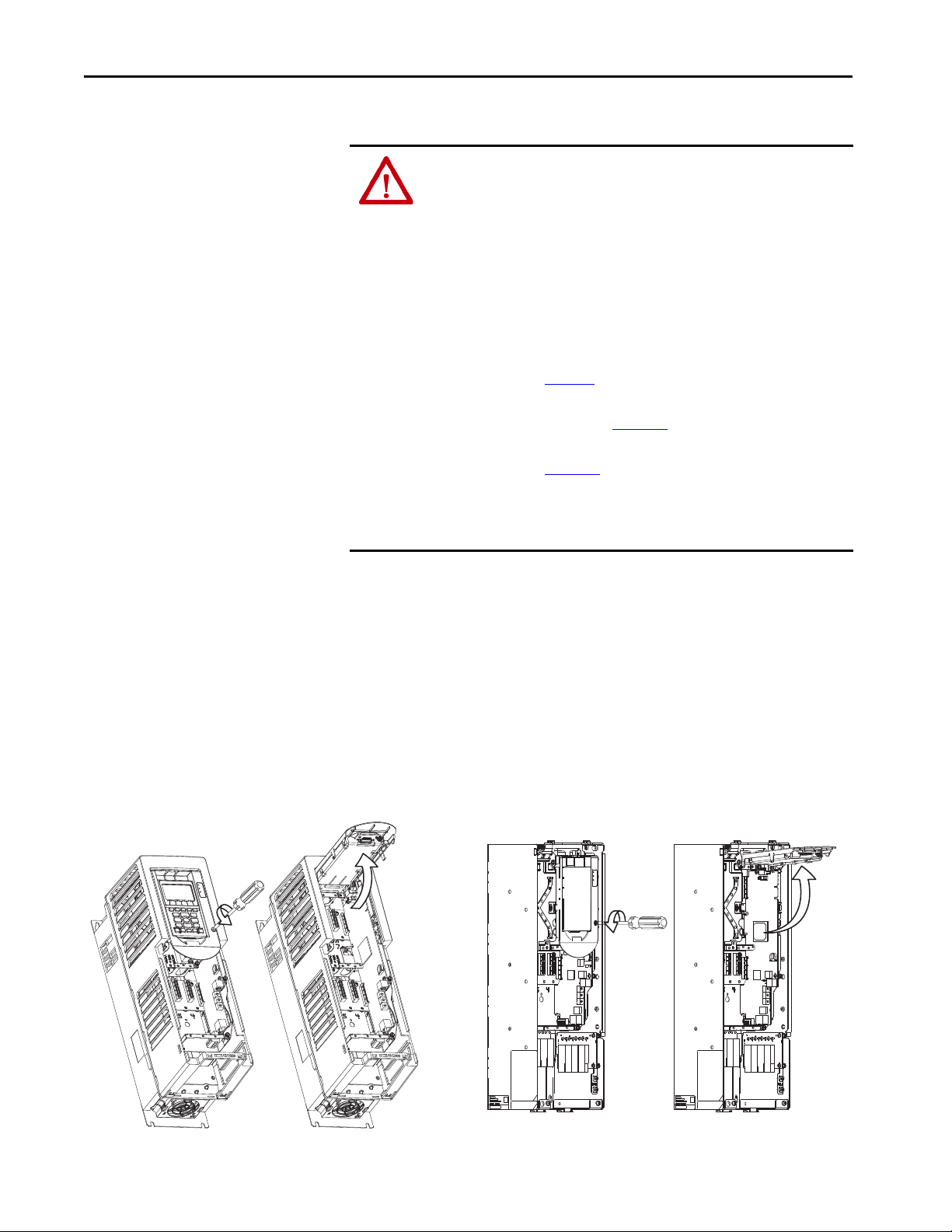
Access the Control Pod
The option module is installed in the drive control pod. Different drives have
different ways to access the control pod. To access the control pod, follow these
steps.
1. Remove the door or cover.
2. Loosen the retention screw on the HIM cradle.
3. Lift the cradle until the latch engages.
See the installation instructions for your drive for more information.
Figure 1 - Access the Control Pod.
30 Rockwell Automation Publication 750-UM005C-EN-P - February 2021
Page 31

Chapter 2
PowerFlex 755 AC Drive
SAFETY Jumper
(jumper is removed)
Hardware ENABLE Jump er
(jumper in place)
PowerFlex 755T Drive Products
SAFETY Jumper
(jumper is removed)
Hardware ENABLE Jumper
(jumper in place)
Set the SAFETY and Hardware ENABLE Jumpers
The PowerFlex 755/755T drive products ship with the safety jumper
(SAFETY) installed.
If the Integrated Safety Functions option module is installed, the control board
SAFETY jumper must be removed. If the SAFETY jumper is not removed, a
‘Safety Jumper In’ fault occurs.
IMPORTANT PowerFlex 755 drives (frames 8…10) control boards do not have a SAFETY
jumper.
If the Integrated Safety Functions option module is installed, the control board
hardware ENABLE jumper must be installed. If the hardware ENABLE
jumper is not installed, a ‘HW Enbl Jmpr Out’ fault occurs (only frames 1…7
of PowerFlex 755 drives and all frame sizes of PowerFlex 755T drive products).
Figure 2 - PowerFlex 755 Drives Jumper Locations, Frames 1…7
Figure 3 - PowerFlex 755T Drive Products Jumper Locations (all frame sizes)
Rockwell Automation Publication 750-UM005C-EN-P - February 2021 31
Page 32

Chapter 2
Install the Safety Option Module
To install the Integrated Safety Functions option module in a drive port, follow
these steps:
1. Firmly press the module edge connector into the desired port.
IMPORTANT The Integrated Safety Functions option module can be installed in
ports 4, 5, or 6 when used in Standard I/O mode. When used in an
Integrated Motion application, the Integrated Safety Functions
option module must be installed in Port 6.
2. Tighten the top and bottom retaining screws.
– Recommended torque = 0.45 N•m (4.0 lb•in)
– Recommended screwdriver = T15 Hexalobular
IMPORTANT Do not overtighten the retaining screws.
IMPORTANT Only one safety option module can be installed in a drive. Multiple
safety option modules or duplicate safety option module
installations are not supported.
Figure 4 - PowerFlex 755 Drives, Frames 1…7
32 Rockwell Automation Publication 750-UM005C-EN-P - February 2021
Page 33

Chapter 2
Feedback Installation Guidelines
Follow these guidelines for the Integrated Safety Functions option module.
Feedback Devices
The Integrated Safety Functions option module can be used with one of the
following feedback devices when safe feedback monitoring is used:
• Dual-incremental Encoder module, catalog number 20-750-DENC-1
• Universal Feedback module catalog number 20-750-UFB-1
Only one feedback card can be used in conjunction with the Integrated Safety
Functions module. For information on the supported encoder types for a given
feedback device, see Encoder Considerations
Port Assignment
Follow these guidelines for port assignment:
• The Integrated Safety Functions option module and the feedback device
must be installed on the same backplane using ports 4, 5, or 6.
• When used in an Integrated Motion application, the Integrated Safety
Functions option module must be installed in port 6.
• Only one safety option module can be installed in a drive. Multiple
safety options or duplicate safety option installations are not supported.
in Chapter 1.
Jumper Settings
Follow these guidelines for jumper settings:
• Verify the hardware enable jumper (ENABLE) on the main control
board is installed. See Figure 2
the drive will fault when powered up.
• Verify the safety enable jumper (SAFETY) on the main control board is
removed (Frames 1…7 only). See Figure 2
or Figure 3 for location. If not installed,
or Figure 3 for location.
Rockwell Automation Publication 750-UM005C-EN-P - February 2021 33
Page 34

Chapter 2
Si0
SC
Si1
SC
SP
To1
Si2
SC
Si3
To0
So0
SC
So1
NC
I/O Wiring
This section describes the onboard safety I/O and wiring considerations. A
power supply must be connected between the SP and SC terminals in order for
the safety I/O to be used. See Power Supply Requirements
on page 35 for
information on selecting a power supply.
IMPORTANT External 24V power is only required to the module when hardwired safety is
used. It is NOT required when the module is used for networked safety
operation.
Table 13 - Terminal Designation
Terminal Name Description
To1 Test Output 1 Test 24V DC output 1
Si2 Safety Input 2 Safety 24V DC input 2
SC Safety Common Safety power common
Si3 Safety Input 3 Safety 24V DC input 3
To0 Test Output 0 Test 24V DC output 0
NC No Connection
So0 Safety Output 0 Safety 24V DC output 0
SC Safety Common Safety power common
So1 Safety Output 1 Safety 24V DC output 1
Si0 Safety Input 0 Safety 24V DC input 0
SC Safety Common Safety power common
Si1 Safety Input 1 Safety 24V DC input 1
SC Safety Common
SP Safety Power Safety 24V DC power
Safety power common (required if safety I/O used)
(required if safety I/O used)
For examples of wiring devices to the safety I/O, see the Guard I/O™ EtherNet/
IP Safety Modules User Manual, publication
1791ES-UM001
.
For technical specifications of the safety I/O, see Integrated Safety Functions
Option Module Specifications in Appendix B.
Cabling
Follow these guidelines for cabling:
• Safety wiring must be protected against external damage by cable ducts,
conduit, armored cable, or other means.
• Shielded cable is required.
• When installed in a PowerFlex 755 Frame 8 or larger drive, an EMC
Core Kit, catalog number 20-750-EMCSSM1-F8, is required.
34 Rockwell Automation Publication 750-UM005C-EN-P - February 2021
Page 35

Power Supply Requirements
Chapter 2
IMPORTANT The external power supply must conform to the Directive 2006/95/EC Low
Voltage by applying the requirements of EN61131-2 Programmable
Controllers, Part 2 - Equipment Requirements and Tests, and one of the
following:
• EN60950 - SELV (Safety Extra Low Voltage)
• EN60204 - PELV (Protective Extra Low Voltage)
• IEC 60536 Safety Class III (SELV or PELV)
• UL 508 Limited Voltage Circuit
• 24V DC ±10% must be supplied by a power supply that complies with
IEC 60204 and IEC 61558-1.
For more information, see the guidelines in Industrial Automation Wiring and
Grounding Guidelines, publication 1770-4.1
.
Rockwell Automation Publication 750-UM005C-EN-P - February 2021 35
Page 36

Chapter 2
Notes:
36 Rockwell Automation Publication 750-UM005C-EN-P - February 2021
Page 37

Chapter 3
Safety I/O
This chapter provides information that is related to the embedded safety inputs
and outputs on the Integrated Safety Functions option module.
Top ic Pa ge
Safety Inputs 37
Safety Outputs 50
Safety Inputs
Read this section for information about safety inputs and their operation
modes. The safety inputs can be used in a single or dual-channel configuration
for monitoring a safety input device. A safety input can also be configured for
external pulse testing with an associated test output.
Safety Input Operation
The Integrated Safety Functions option module provides two modes of
operation for its safety inputs: Safety Input with External Pulse Tests and
Standard Input.
The safety inputs also support configuring a sample delay time. You can
configure both on→off and off→on sample delay times for each input point. You
can also configure a latch error time, which specifies the minimum amount of
time that a safety input alarm is reported.
Safety Input with External Pulse Tests Operation
A test output can be used in combination with a safety input for short-circuit
detection. Configure the test output as a pulse test source and configure the
safety input as ‘Used with Test Output’. Test Output 0 is associated with safety
inputs 0 and 2. Test Output 1 is associated with safety inputs 1 and 3.
When the external input contact is closed, a test pulse is output from the test
output terminal to diagnose the field wiring and input circuitry. By using this
function, short circuits between input signal lines and the power supply
(positive side), and short circuits between redundant input signal lines of one
external device can be detected. Safe wiring by customer action is required.
Rockwell Automation Publication 750-UM005C-EN-P - February 2021 37
Page 38

Chapter 3
OFF
Typic al Pulse
Test Period
300ms
Typical
Pulse
Width
100µs
Typ ica l Pu lse
Tes t Pe ri od
300 ms
Typ ic al
Pulse
Widt h
500 μs
ON
OFF
External Contact
So0
To0
To1
Si2
Si3
SC
So1
SC
NC
SP
SC
Si0
SC
Si1
Short Circuit Between Input Signal Lines and
Power Supply (positive side)
Short Circuit Between Input Signal Lines
External
Contac t
External
Contac t
Table 14 - Typical External Pulse Width and Period
Pulse Width Period
500 μs 300 ms
Figure 5 - Test Pulse in a Cycle
IMPORTANT When using external pulse testing in single-channel mode, the demand rate
of the input must be greater than 30 seconds.
Figure 6 - Short-circuit Between Input Signal Lines
38 Rockwell Automation Publication 750-UM005C-EN-P - February 2021
Page 39

ON
OFF
Pulse Test
Output
Normal Operation
ON
OFF
External Device
ON
OFF
Safety Input
Ter m in al
ON
OFF
Safety Input
Val ue
OK
ALARM
Safety Input
Status
ON
OFF
Pulse Test
Output
ON
OFF
External Device
ON
OFF
Safety Input
Terminal
OK
ALARM
Safety Input
Status
ON
OFF
Safety Input
Val ue
Pulse Test
Occurs
Pulse Test
Occurs
Alarm Detected
Alarm Operation
Chapter 3
Latch Input Error Operation in Single Channel Mode
The safety input subsystem allows for a configurable time for which an alarm
state is held. This is referred to as Input Latch Error Time. In single channel
mode, the input latch error time describes the period between when the alarm
condition is removed and when the safety input stops reporting the alarm.
Figure 7
See Safety Input Alarm Recovery
alarm.
Figure 7 - Single Channel Input Latch Error Behavior (not to scale)
shows the operation of input latch error time in single channel mode.
on page 49 for information on removing an
Rockwell Automation Publication 750-UM005C-EN-P - February 2021 39
Page 40

Chapter 3
ON
OFF
Pulse Test
Output
Normal Operation
ON
OFF
External Device
ON
OFF
Safety Input
Ter m in al
ON
OFF
Safety Input
Val ue
OK
ALARM
Safety Input
Status
ON
OFF
Pulse Test
Output
ON
OFF
External Device
ON
OFF
Safety Input
Ter m in al
OK
ALARM
Safety Input
Status
ON
OFF
Safety Input
Val ue
Pulse Test
Occurs
Pulse Test
Occurs
Alarm Detected
Alarm Operation
Single Channel Safety Input Status Data
Figure 8 describes the status and value that is reported by the Safety IO
subsystem for normal and alarm states. In normal operation, the Safety Input
value reported is the value being read on the input terminal. The Safety Input
status is on. When a fault is detected, the Safety Input value and status are
forced off.
Figure 8 - Single Channel Normal Operation and Alarm Detection (not to scale)
40 Rockwell Automation Publication 750-UM005C-EN-P - February 2021
Page 41

Chapter 3
Dual-channel Safety Input Operation
To support redundant safety devices, the consistency between signals on two
input points can be evaluated. This is referred to as Dual-channel operation.
Two modes are available when using dual-channel inputs: equivalent and
complementary.
When using either dual-channel input mode, the time from when a
discrepancy is created and when the discrepancy is reported can be configured.
This is referred to as Discrepancy Time. The configured discrepancy time is
0 (deactivated)…65,530 ms in increments of 1 ms.
IMPORTANT The dual-channel function is used with two consecutive inputs that are
paired together, this process starts at an even input number, such as
inputs 0 and 1; 2 and 3; and so on.
IMPORTANT Do not set the discrepancy time longer than necessary. The purpose of
the discrepancy time is to allow for normal differences between contact
switching when demands are placed on safety inputs. For discrepancy
checking to operate correctly, only one demand on the safety input is
expected during the discrepancy time. If the discrepancy time is set too
high, and multiple demands occur during this time, then both safety
input channels will alarm.
Ta b l e 1 5
shows the relation between physical input terminal states and the data
and status reported by the Safety Input subsystem.
Table 15 - Terminal Input Status and Controller I/O Data
Dual-channel Mode Input Terminal Controller Input Data and Status Dual-channel
Si0 Si1 Safety
Input 0 Data
Dual-channels, Equivalent OFF OFF OFF OFF OK ON OFF OK
OFF ON OFF OFF ALARM OFF OFF Alarm
ON OFF OFF OFF ALARM OFF OFF Alarm
ON ON ON ON OK ON ON OK
Dual-channels, Complementary OFF OFF OFF ON ALARM OFF OFF Alarm
OFF ON OFF ON OK ON OFF OK
ON OFF ON OFF OK ON ON OK
ON ON OFF ON ALARM OFF OFF Alarm
Safety
Input 1 Data
Safety
Input 0 Status
Safety
Input 1 Status
Resultant
Data
Dual-channel
Input
Status
Rockwell Automation Publication 750-UM005C-EN-P - February 2021 41
Page 42
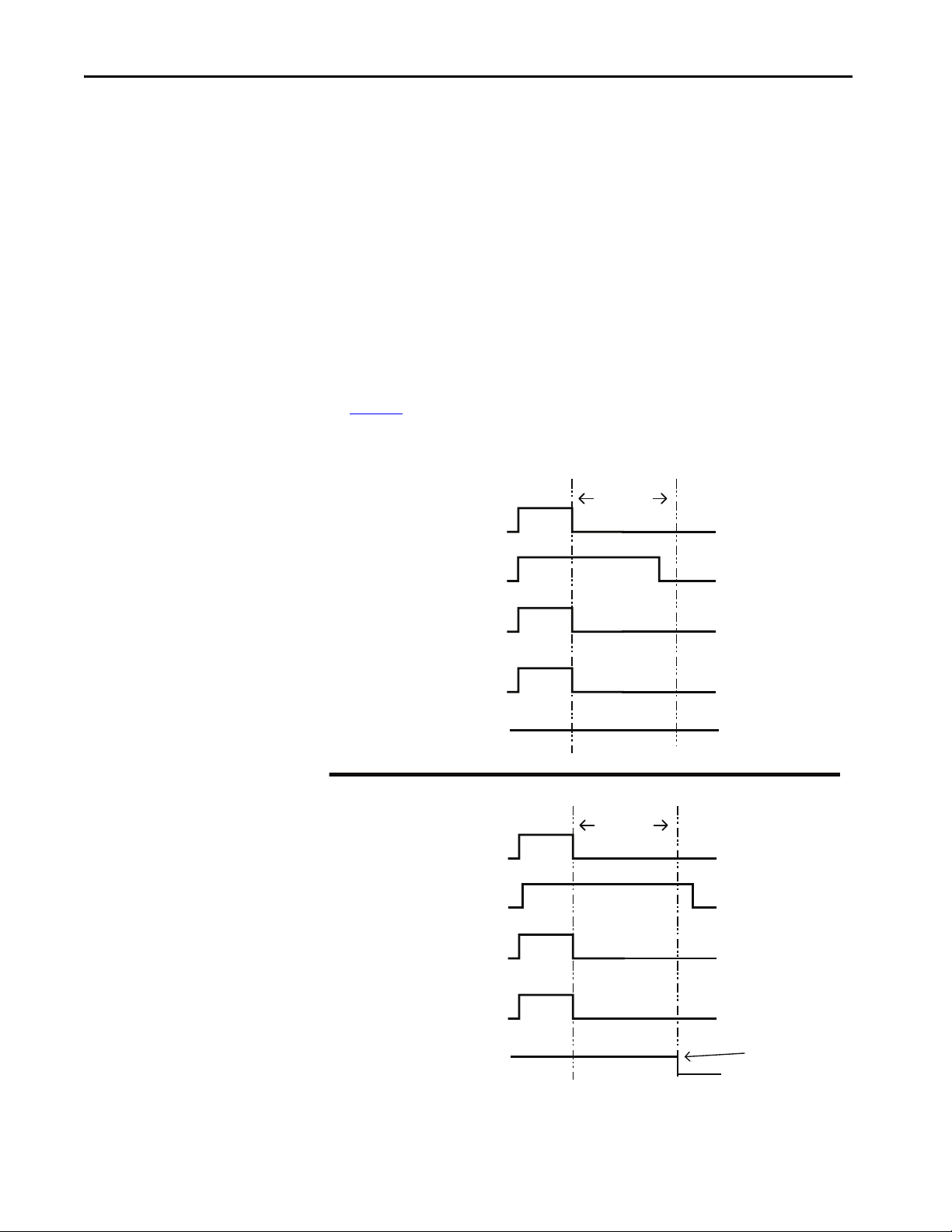
Chapter 3
ON
OFF
Safety Input 0
Ter m in al
Normal Operation
ON
OFF
Safety Input 1
Ter m in a l
ON
OFF
Safety Input 0
Val ue
ON
OFF
Safety Input 1
Valu e
OK
ALARM
Dual Channel
Status
ON
OFF
Safety Input 0
Terminal
ON
OFF
Safety Input 1
Terminal
ON
OFF
Safety Input 0
Val ue
OK
ALARM
Dual Channel
Status
ON
OFF
Safety Input 1
Valu e
Discrepancy
Time
Alarm Detected
Discrepancy
Time
Alarm Operation
Equivalent Dual-channel Input Operation
In Equivalent mode, both inputs of a pair must typically be in the same
(equivalent) state. When a transition occurs in one channel of the pair, before
the transition of the second channel of the pair, a discrepancy occurs. If the
second channel transitions to the appropriate state before the discrepancy time
elapses, the inputs are considered equivalent.
If the second transition does not occur before the discrepancy time elapses, the
channels transition to the alarm state. In the alarm state, the input and status
for both channels are set low (off ). When configured as an equivalent dual
pair, the data bits for both channels are sent to the controller as equivalent,
both high or both low.
Figure 9
shows the operation of dual channel equivalent inputs under normal
and alarm conditions.
Figure 9 - Equivalent, Normal Operation, and Alarm Detection (not to scale)
42 Rockwell Automation Publication 750-UM005C-EN-P - February 2021
Page 43

Chapter 3
ON
OFF
Safety Input 0
Ter m in al
Normal Operation
ON
OFF
Safety Input 1
Ter m in al
ON
OFF
Safety Input 0
Val ue
ON
OFF
Safety Input 1
Val ue
OK
ALARM
Dual Channel
Status
ON
OFF
Safety Input 0
Ter m in al
ON
OFF
Safety Input 1
Terminal
ON
OFF
Safety Input 0
Val ue
OK
ALARM
Dual Channel
Status
ON
OFF
Safety Input 1
Val ue
Discrepancy
Time
Alarm Detected
Alarm Operation
Discrepancy
Time
Complementary Dual-channel Input Operation
In Complementary mode, the inputs of a pair are typically in the opposite
(complementary) state. When a transition occurs in one channel of the pair
before the transition of the second channel of the pair, a discrepancy occurs. If
the second channel transitions to the appropriate state before the discrepancy
time elapses, the inputs are considered complementary.
If the second transition does not occur before the discrepancy time elapses, the
channels transition to the alarm state. The alarm state of complementary
inputs is the even-numbered input turned off and the odd-numbered input
turned on. If in the alarm state, both channel status bits are set low. When
configured as a complementary dual-channel pair, the data bits for both
channels are sent to the controller in complementary, or opposite states.
Figure 10
shows the operation of dual-channel complementary inputs under
normal and alarm conditions.
Figure 10 - Complementary, Normal Operation and Alarm Detection (not to scale)
Rockwell Automation Publication 750-UM005C-EN-P - February 2021 43
Page 44

Chapter 3
Standard Input Operation
When a safety input is configured for standard input operation, no diagnostics
are performed on the input. Unlike safety inputs, a standard input cannot be
used with pulse testing and can only be used in single channel mode. A
standard input can still be configured to have an onoff and offon filter
time.
IMPORTANT Do not use standard inputs for safety purposes.
Table 16 - Standard Input Value Attribute
Parameter Value Description
Service Code 0x0E Get Attribute Single
Class 0x3D Safety Discrete Input Point Object
Instance i + 1 Safety Input Instance (where i is the number of the safety input being used as a
standard input)
Data Type BYTE 8 Bits
Attribute 0xA Filtered Input Value
0 = Input OFF
1 = Input ON
Safety Input Safety Data
The Safety Input data of the Integrated Safety Functions module can be
monitored through:
• Safety Input Assembly
•DPI™ Parameters
•CIP™ Messaging
IMPORTANT Only the Safety Input Value and Status in the Safety Input Assembly can be
considered safety data. Input values read through DPI parameters or CIP
messages are not safety data.
The following Safety Input data is available in the Integrated Safety Functions
Module:
• Safety Input Status
• Safety Input Value
• Safety Input Valid
Each safety input point reports its own status, value, and valid attributes.
IMPORTANT If a safety input is configured for standard input mode, its associated safety
data is forced in the safe state.
Do not use standard inputs for safety purposes.
44 Rockwell Automation Publication 750-UM005C-EN-P - February 2021
Page 45

Chapter 3
Safety Input Status
The safety input status indicates whether an alarm is present in the safety input
point. The safety input status is provided in the safety input assembly, as shown
in Ta b l e 1 7
CIP messaging.
The safety input status is also provided in the first four bits of device parameter
P13 [Safety IO Status].
Table 17 - Safety Input Assembly Tags for Safety Input Status
. Ta b l e 1 8 describes the attributes for reading the safety status via
Safety Input Assembly Tag Name
(safety controller to S4 option)
module:SI.InputStatus SINT A collection of safety input values and status for each
module:SI.In01Status [4] Status of Safety Input 0
module:SI.In01Status [5] Status of Safety Input 1
module:SI.In02Status [6] Status of Safety Input 2
module:SI.In03Status [7] Status of Safety Input 3
Type/[bit] Description
safety input
0 = Alarm
1 = OK
0 = Alarm
1 = OK
0 = Alarm
1 = OK
0 = Alarm
1 = OK
Table 18 - MSG Configuration for Safety Input Status
Parameter Value Description
Service Code 0x0E Get attribute single
Class 0x3D Safety Discrete Input Point Object
Instance i + 1 Where i is the number of the safety input
Data Type USINT Unsigned integer value
Attribute 0x4
4
Safety Status
0 = Alarm
1 = OK
Safety Input Value
The safety input value is the value of the input after safety and on/off delay
evaluations when the safety input is not in the alarm state. If the safety input is
in the alarm state, this value will always be 0.
The safety input value is provided in the safety input assembly, as shown in
Ta b l e 1 9
messaging. The safety input value is also provided in the first four bits of device
parameter P12 [Safety IO Values].
Rockwell Automation Publication 750-UM005C-EN-P - February 2021 45
. Ta b l e 2 0 describes the attributes for reading the safety value via CIP
Page 46

Chapter 3
Table 19 - Safety Input Assembly Tags for Safety Input Values
Safety Input Assembly Tag Name
(safety controller to S4 option)
module:SI.InputStatus SINT A collection of safety input values and status for each
module:SI.In00Data [0] Value of Safety Input 0
module:SI.In01Data [1] Value of Safety Input 1
module:SI.In02Data [2] Value of Safety Input 2
module:SI.In03Data [3] Value of Safety Input 3
Type/[bit] Description
safety input
0 = OFF
1 = ON
0 = OFF
1 = ON
0 = OFF
1 = ON
0 = OFF
1 = ON
Table 20 - MSG Configuration for Safety Input Value
Parame ter Value Description
Service Code 0x0E Get attribute single
Class 0x3D Safety Discrete Input Point Object
Instance i + 1 Where i is the number of the safety input
Data Type USINT Unsigned integer value
Attribute 0x7
7
Safety Input Logical Value
0 = OFF
1 = ON
Safety Input Valid
When set, the safety input valid attribute indicates that the safety input is
configured for safety use and producing valid data. If this value is not set, the
data that is associated with the safety input is no longer valid safety data.
IMPORTANT The Safety Input Valid attribute should be checked before using safety input
data in a safety application.
The safety input valid attribute is provided in the safety input assembly, as
shown in Ta b l e 2 1
via CIP messaging.
46 Rockwell Automation Publication 750-UM005C-EN-P - February 2021
. Ta b l e 2 2 describes the attributes for reading the safety value
Page 47

Table 21 - Safety Input Assembly Tags for Safety Input Valid
Chapter 3
Safety Input Assembly Tag Name
(safety controller to S4 option)
module:SI.IOSuppor t SINT A collec tion of bits describing safety IO functionality
module:SI.In00Valid [0]
module:SI.In01 Valid [1]
module:SI.In02 Valid [2]
module:SI.In03 Valid [3]
Type/[bit] Description
Safety Input 0 Valid
0 = Data invalid
1 = Data valid
Safety Input 1 Valid
0 = Data invalid
1 = Data valid
Safety Input 2 Valid
0 = Data invalid
1 = Data valid
Safety Input 3 Valid
0 = Data invalid
1 = Data valid
Table 22 - MSG Configuration for Safety Input Valid
Configuration Item Value Description
Service Code 0x0E Get attribute single
Class 0x3D Safety Discrete Input Point Object
Instance i + 1 Where i is the number of the safety input
Data Type USINT Unsigned integer value
Attribute 0x64
100
Safety Input Valid
0 = Data invalid
1 = Data Valid
Safety Input Alarms
The safety input logic can detect configuration, circuit, and discrepancy errors
for each safety input. When an error is detected, the associated safety input
data is put into the safe state, and the alarm type attribute is set.
Configuration Error
A configuration error occurs when a safety input’s configuration data is invalid.
If this error occurs, check to make sure that the configuration attributes for the
safety input are valid. A configuration error can also occur if the safety input is
selected for external pulse testing and the associated test output’s configuration
is not valid for this mode.
Circuit Error
A circuit error occurs in a safety input when a pulse test fails. There are two
types of circuit errors that can be reported:
• Internal Circuit Error
• External Circuit Error
Rockwell Automation Publication 750-UM005C-EN-P - February 2021 47
Page 48

Chapter 3
An internal circuit error occurs when an internal pulse test fails. This means
that circuitry inside the module has failed. An internal circuit error may not be
recoverable; replacing the module may be required.
An external circuit error occurs when pulse testing by the safety input’s
associated test output fails. This error indicates the input circuitry external to
the card has failed.
Discrepancy and Dual Channel Errors
The discrepancy and dual channel errors are related, as a discrepancy can only
occur when the safety input is in dual channel mode. A discrepancy error
occurs when one of the dual channel safety inputs is not reporting the expected
safety input value. The safety input with the unexpected value reports the
discrepancy error. The other associated safety input will also be put in the safe
state and report a dual channel error alarm.
Determining Safety Input Alarm Type
To determine if a safety input is reporting an alarm, examine the safety input’s
input status attribute (see Safety Input Status
accessing this attribute). If the input is reporting an alarm, the alarm type can
be accessed through DPI parameters or CIP messaging.
on page 45 for information on
Determine Safety Input Alarm Type with DPI Parameters
To read an alarm type of safety input with DPI parameters, follow these steps:
1. Set device parameter P14 [Input Alarm Indx] to the integer value i +1,
where i is the number of the safety input.
2. Read device parameter P15 [Input Alarm].
Determine Safety Input Alarm Type with CIP Messaging
The safety input alarm type can also be read via CIP messaging. See Ta b l e 2 1
for the attributes that are required to read the alarm type.
48 Rockwell Automation Publication 750-UM005C-EN-P - February 2021
Page 49

Chapter 3
Table 23 - MSG Configuration for Safety Input Alarm Type
Parame ter Val ue Description
Service Code 0x0E Get attribute single
Class 0x3D Safety Discrete Input Point Object
Instance i + 1 Where i is the number of t he safety input
Data Type USINT Unsigned integer value
Attribute 0x6E
110
Safety Input Alarm Type
0 = No Alarm
1 = Configuration Error
2 = External C ircuit Error
3 = Internal Circ uit Error
4 = Discrepancy Error
5 = Dual Channel error
Safety Input Alarm Recovery
If an error is detected, the safety input data remains in the off state. Follow this
procedure to activate the safety input data.
1. Remove the cause of the error.
2. Place the safety input (or safety inputs if in dual channel mode) into the
safe state.
The safety input status turns on (alarm cleared) after the input-error
latch time has elapsed.
TIP If the latch error time has expired, but the safety input is not yet in the safe
state, the alarm will not be cleared. Once the safety input is in the safe state,
the alarm will clear immediately.
Input Delays
Each safety input has a configurable filter time for sampling the input. Both the
onoff and offon filter values can be configured. Unlike other
configuration values, these values can be configured in standard input mode
Off–on Delay
An input signal is treated as logic 0 during the on-delay time (0…126 ms, in
increments of 1 ms) after the rising edge of the input contact. The input only
turns on if the input contact remains on after the on-delay time has elapsed.
This delay helps prevent rapid changes of the input data due to contact bounce.
Rockwell Automation Publication 750-UM005C-EN-P - February 2021 49
Page 50

Chapter 3
ON
OFF
ON
OFF
Input Signal
Safety Input Value
On-delay
Input Signal
ON
OFF
ON
OFF
Safety Input Value
Off-delay
Figure 11 - Off-on Delay
On-off Delay
An input signal is treated as logic 1 during the off-delay time (0…126 ms, in
increments of 1 ms) after the falling edge of the input contact. The input only
turns off if the input contact remains off after the off delay time has elapsed.
This delay helps prevent rapid changes of the input data due to contact bounce.
Figure 12 - On-off Delay
Safety Outputs
Use With PowerFlex 750-Series ATEX Option Module
The 20-750-ATEX option can be wired to an S4 safety input. This is a generalpurpose safety input, so the user is responsible for the GuardLogix
programming logic to tie the input to the SO.STOOutput tag. See the
PowerFlex 750-Series ATEX Option Module User Manual, publication
750-UM003
, for more information.
Read this section for information about safety outputs. The safety outputs can
operate in single channel mode or dual channel mode. In either mode, the
safety output can also be configured to run pulse test diagnostics.
Safety Output with Test Pulse
When the safety output is on, the safety output can be configured to pulse test
the safety output channel. By using this function, you can continuously test the
ability of the safety output to remove power from the output terminals of the
module. If an error is detected, the safety output data and individual safety
output status turn to the safe state.
50 Rockwell Automation Publication 750-UM005C-EN-P - February 2021
Page 51

Chapter 3
Typ ic al
Pulse
Widt h
500 μs
Typical Pulse
Tes t Pe ri od
300 ms
ON
OFF
Figure 13 - Test Pulse in a Cycle
Table 24 - Typical External Pulse Width and Period
Pulse Width Period
500 μs 300 ms
IMPORTANT To help prevent the test pulse from causing the connected device to
malfunction, pay careful attention to the input response time of the device
that is connected to the output.
Single-channel Mode
IMPORTANT When using pulse testing in single channel mode, the demand rate of the
output must be greater than 30 seconds.
In single-channel mode, when the safety output is requested to the on state, the
output will turn on if there is no alarm. If an alarm is detected on the channel,
the safety output data and safety output status turn off, and commanding the
output will have no effect.
Rockwell Automation Publication 750-UM005C-EN-P - February 2021 51
Page 52

Chapter 3
ON
OFF
Safety Output
Terminal
Normal Operation
ON
OFF
Safety Output
Valu e
ON
OFF
Safety Output
Status
ON
OFF
Safety Output
Terminal
Alarm Operation
ON
OFF
Safety Output
Val ue
ON
OFF
Safety Output
Status
Alarm Detected
ON
OFF
Safety Output 0
Val ue
OK
ALARM
Safety Output
Status
Output
Latch Error
Time
Alarm Detected
Alarm
Condition
Removed and
Safety Output
Value i n Safe
State
Alarm Cleared
Figure 14 - Single-channel Setting (not to scale)
Latch Output Error Operation in Single Channel Mode
The safety output subsystem allows for a latch error time to be configured. The
latch error time is the minimum time an output alarm will be held before the
alarm can be cleared. This latch error time is used by all safety outputs.
Figure 15
mode. See Safety Output Alarm Recovery
clearing alarms.
Figure 15 - Single Channel Output Latch Error Behavior
shows the behavior of the safety output latch time in single channel
on page 60 for information on
52 Rockwell Automation Publication 750-UM005C-EN-P - February 2021
Page 53

Chapter 3
ON
OFF
Safety Output 0
Normal Operation
ON
OFF
Safety Output 1
ON
OFF
Dual Channel
Output Status
Alarm Operation
ON
OFF
Safety Output 0
Valu e
ON
OFF
Safety Output 1
Val ue
ON
OFF
Dual Channel
Output Status
Alarm Detec ted
Dual-channel Mode
When the data of both channels is in the on state, and neither channel has an
alarm, the outputs are turned on. The status is normal. If an alarm is detected
on one channel, the safety output data and individual safety output status turn
off for both channels.
Figure 16
shows the operation of dual channel outputs under normal and alarm
conditions.
Figure 16 - Dual-channel Setting (Not to Scale)
Latch Output Error Operation in Dual Channel Mode
In dual channel mode, the output latch error time describes the period between
when the alarm condition is removed and when the dual channel safety output
stops reporting the alarm. Figure 17
latch error time in dual channel mode. When one or both of the associated
output points has an alarm (such as a Pulse Test Failure), and there is a
discrepancy between the two channels, the alarm and discrepancy must be
cleared before the latch error timer begins counting. Figure 18
special case operation. See Safety Output Alarm Recovery
information on removing an alarm.
Rockwell Automation Publication 750-UM005C-EN-P - February 2021 53
shows the normal operation of output
shows this
on page 60 for
Page 54

Chapter 3
OK
ALARM
Dual Channel
Safety Output
Status
Output
Latch Error
Time
Alarm Detec ted
Alarm
Condition
Removed and
Output Values
in Safe State
Alarm Cleared
ON
OFF
Safety Output 0
Val ue
ON
OFF
Safety Output 1
Valu e
OK
ALARM
Dual Channel
Safety Output
Status
ON
OFF
Safety Output 0
Valu e
ON
OFF
Safety Output 1
Val ue
OK
ALARM
Dual Channel
Safety Output
Status
Dual Channel
Equivalent Mode
Output
Latch Error
Time
Discrepancy
Removed
Alarm Detec ted
Discrepancy
Detected
Alarm Cleared
Figure 17 - Dual Channel Output Latch Error Behavior
Figure 18 - Dual Channel Output Latch Error Behavior With Alarm and Discrepancy (not to scale)
54 Rockwell Automation Publication 750-UM005C-EN-P - February 2021
Page 55

Chapter 3
Safety Output Safety Data
The Safety Output data of the Integrated Safety Functions module can be
monitored through:
• Safety Input Assembly
•DPI Parameters
•CIP Messaging
The following Safety Output data is available in the Integrated Safety
Functions Module:
•Safety Output Status
•Safety Output Ready
•Output Monitor Value
Each safety output point reports its own status, monitor value, and ready
attributes.
Safety Output Status
The safety output status indicates whether an alarm is present in the safety
output point. The safety output status is provided in the safety input assembly,
as shown in Ta b l e 2 5
. Ta b l e 2 6 describes the attributes for reading the safety
status via CIP messaging. The safety output status is also provided in bits 6 and
7 of device parameter P13 [Safety IO Status].
Table 25 - Safety Input Assembly Tags for Safety Output Status
Safety Input Assembly Tag Name
(safety controller to S4 option)
module:SI.OutputStatus SINT A collection of safety output status, safety output
module:SI.Out00Status [4] Status of Safety Output 0
module:SI.Out01Status [5] Status of Safety Output 1
Table 26 - MSG Configuration for Safety Output Status
Parameter Value Description
Service Code 0x0E Get attribute single
Class 0x3B Safety D iscrete Output Point Object
Instance i + 1 Where i is the number of the safety output
Data Type USINT Unsigned integer value
Attribute 0x5
5
Type / [bit] Description
monitor values, and test output status
0 = Alarm
1 = OK
0 = Alarm
1 = OK
Safety Status
0 = Alarm
1 = OK
Rockwell Automation Publication 750-UM005C-EN-P - February 2021 55
Page 56

Chapter 3
Safety Output Ready
When set, the safety output ready attribute indicates that the safety output is
configured for safety use and ready to be commanded.
IMPORTANT Check the Safety Output Ready attribute before commanding the safety
output.
The safety output ready attribute is provided in the safety input assembly, as
shown in Ta b l e 2 7
Ready attribute via CIP messaging.
Table 27 - Safety Input Assembly Tags for S afety Output Ready
. Ta b l e 2 8 describes the attributes for the Safety Output
Safety Input Assembly Tag Name
(safety controller to S4 option)
module:SI.IOSuppor t SINT A collection of bits describing safety IO
module:SI.Out00Ready [4] Safety Output 0 Ready
module:SI.Out01Ready [5] Safety Output 1 Ready
Type/[bit] Description
functionality
0 = Not Ready
1 = Ready
0 = Not Ready
1 = Ready
Table 28 - MSG Configuration for Safety Output Ready
Parameter Value Description
Service Code 0x0E Get attribute single
Class 0x3B Safety Discrete Output Point Object
Instance i + 1 Where i is the number of the safety output
Data Type USINT Unsigned integer value
Attribute 0x64
100
Safety Status
0 = Not Ready
1 = Ready
Output Monitor Value
IMPORTANT Safety Output Monitor Value is not safety data and has no defined safe state.
Use Output Monitor Value for diagnostic purposes only.
The output monitor value of a safety output is the value of the output that is
read by module. It is expected that the output monitor value is the same as the
commanded safety output value in normal operation. The output monitor
value can be used to diagnose output alarms.
The output monitor value is provided in the safety input assembly, as shown in
Ta b l e 2 9
56 Rockwell Automation Publication 750-UM005C-EN-P - February 2021
. Ta b l e 3 0 describes the attributes for reading the output monitor
Page 57

Chapter 3
value via CIP messaging. The output monitor value is also provided in bits 6
and 7 of DPI device parameter P12 [Safety IO Values].
Table 29 - Safety Input Assembly Tags for S afety Output Monitor Value
Safety Input Assembly Tag Name
(safety controller to S4 option)
module:SI.OutputStatus SINT A collection of safety output status, safety output
module:SI.Out00Monitor [0] Output Monitor Value of Safety Output 0
module:SI.Out01Monitor [1] Output Monitor Value of Safety Output 1
l
Type/[bit] Description
monitor values, a nd test output status
0 = OFF
1 = ON
0 = Not Ready
1 = Ready
Table 30 - MSG Configuration for Safety Output Monitor Value
Parameter Value Description
Service Code 0x0E Get attribute single
Class 0x3B Safety Discrete Output Point Object
Instance i + 1 Where i is the number of the safety output
Data Type USINT Unsigned integer value
Attribute 0x4
4
Output Monitor Value
0 = OFF
1 = ON
Commanding Safety and Test Outputs
The value of a safety and test outputs can be commanded by setting tags in the
safety output assembly. Ta b l e 3 1
module.
Table 31 - Safety Input Assembly Tags for S afety Output Ready
Safety Input Assembly Tag Name
(safety controller to S4 option)
module:SO.SafetyIOCommands SINT A collection of safety status bits for commanding
module:SO.Out00Output [0] Commanded Safety Output 0 Value
module:SO.Out01Output [1] Commanded Safety Output 1 Value
shows the output command tags of the
Type/[bit] Description
IO values
0 = OFF
1 = ON
0 = OFF
1 = ON
Rockwell Automation Publication 750-UM005C-EN-P - February 2021 57
Page 58

Chapter 3
Safety Output Alarms
The Safety Output logic can detect the following errors:
• Configuration
•Circuit
• Dual Channel Discrepancy (Dual Channel Configuration Only)
• Partner Channel (Dual Channel Configuration Only)
When an error is detected, the associated safety output data is put into the safe
state and the Alarm Type attribute is set.
Configuration Error
A configuration error occurs when a safety output’s configuration data is
invalid. If this error occurs, verify that the configuration attributes for the
safety outputs are valid.
Circuit Error
When a safety output is configured for use with test pulses, a circuit error
occurs when a pulse test fails. There are three types of circuit errors that can be
reported:
•Stuck Low
•Stuck High
•Cross Connection
A stuck low error occurs when the output is expected to be in the on state, but
the feedback indicates the output is in the off state.
A stuck high error occurs when a pulse test expects the output to be in the off
state but the output does not transition to the off state during the pulse test
interval.
A cross connection error occurs when a pulse test of one safety output causes
another safety output to change value. This usually indicates that two outputs
are shorted together.
If a circuit error occurs in a safety output, check the wiring of the safety outputs
for errors.
Dual Channel Discrepancy Error
When the safety outputs are configured for dual channel mode, a dual channel
discrepancy error occurs when there is a mismatch in the commanded output
values of the dual channel outputs. Both outputs will report a Dual Channel
Discrepancy error.
58 Rockwell Automation Publication 750-UM005C-EN-P - February 2021
Page 59

Chapter 3
Partner Channel Error
When the safety outputs are configured for dual channel mode, and one of the
safety outputs experiences a circuit or configuration error, the other safety
output will report a Partner Channel error.
TIP The safety output data will still be placed in the safe state when a Partner
Channel error occurs.
Determining Safety Output Alarm Type
To determine if a safety output is reporting an alarm, examine the safety
output’s output status attribute. See Safety Output Safety Data
information on safety output status. If the output is reporting an alarm, the
alarm type can be accessed through DPI parameters or CIP messaging.
Determine Safety Input Alarm Type with DPI Parameters
on page 55 for
To read an alarm type of safety output with DPI parameters, follow these steps.
1. Set device parameter P16 [Output Alarm Indx] to the integer value i +1,
where i is the number of the safety output
2. Read device parameter P17 [Output Alarm].
Determine Safety Output Alarm Type with CIP Messaging
The safety input alarm type can also be read via CIP messaging. See Ta b l e 3 2
for the attributes that are required to read the alarm type.
Table 32 - MSG Configuration for Safety Output Alarm Type
Parameter Value Description
Service Code 0x0E Get attribute single
Class 0x3B Safety Discrete Output Point Object
Instance i + 1 Where i is the number of the safety output
Data Type USINT Unsigned integer value
Attribute 0x6E
110
Safety Output Alarm Type
0 = No Alarm
1 =Configuration
3 = Stuck Low
4 = Stuck High
5 = Partner Channel
8 = Dual Channel
9 = Cross Connection
Rockwell Automation Publication 750-UM005C-EN-P - February 2021 59
Page 60

Chapter 3
Safety Output Alarm Recovery
If an alarm is detected, the safety outputs are switched to the safe state and
remain in the safe state. Follow this procedure to activate the safety output data
again.
1. Remove the cause of the alarm.
2. Command the safety output (or safety outputs in dual channel mode)
into the safe state.
3. Allow the output-error latch time to elapse and monitor the output
ready attribute and the output status attribute to determine when the
output can be commanded again.
TIP If the latch error time has expired, but the safety output is not yet
commanded to the safe state, the alarm will not be cleared. Once the safety
output is commanded to the safe state, the alarm will clear immediately.
Test Output
The test outputs of the Integrated Safety Function module can be configured
in the following modes:
• Standard Output
•Test Output
•Power Supply Output
ATT EN TI ON : Test Output points that are configured as Pulse Test or Power
Supply become active whenever you apply input power to the module. These
configured functions are independent of the I/O connections to the module.
ATT EN TI ON : If a module with Test Outputs configured as Pulse Test or Power
Supply is incorrectly installed in an application where actuators are connected to these Test Output points, the actuators are activated when input
power is applied.
To prevent this possibility, follow these procedures.
• When installing or replacing a module, be sure that the module is correctly
configured for the application or in the out-of-box condition before applying
input power.
• Reset modules to their out-of-box condition when removing them from an
application.
• Be sure that all modules in replacement stock are in their out-of-box
condition.
60 Rockwell Automation Publication 750-UM005C-EN-P - February 2021
Page 61

Chapter 3
ATT EN TI ON : Do not use test outputs as safety outputs. Test outputs do not
function as safety outputs.
Standard Output Mode
When a test output is configured for standard output mode, the test output
point operates as a general purpose output. The output can be commanded
through the safety output assembly. Ta b l e 3 3
output assembly to command test outputs when in standard output mode.
Table 33 - Safety Output Assembly Tags for Test Output Commands
shows the tags in the safety
Safet y Input Assembly Tag
Name
module:SO.SafetyIOCommands SINT A collection of safety status bits for commanding IO values
module: SO.Test00Output [2] Test Output 0 Value
module: SO.Test01Output [3] Test Output 1 Value
Type / [bit] Description
0 = OFF
1 = ON
0 = OFF
1 = ON
Test Output Mode
When in test output mode, the test output point operates in conjunction with
a safety input to perform pulse testing on the external safety input circuitry.
Please see the Safety Input with External Pulse Tests Operation section for
information on this mode. Commanding the output point via the safety output
assembly will have no effect in this mode.
Power Supply Output
Test Output Data
In power supply output mode, the output point is forced on, and will only shut
off in the case of a critical fault. Commanding the output point via the safety
output assembly will have no effect in this mode.
The Test Output data of the Integrated Safety Functions module can be
monitored through:
• Safety Input Assembly
•DPI Parameters
•CIP Messaging
Rockwell Automation Publication 750-UM005C-EN-P - February 2021 61
Page 62

Chapter 3
The following Test Output data is available in the Integrated Safety Functions
module:
•Test Output Status
•Test Output Ready
Each test output point reports its own status and ready attributes.
IMPORTANT Test Output data is not safety data and cannot be used for safety
applications.
Test Output Status
The test output status indicates whether an alarm is present in the test output
point. When in standard output mode, the status will always be OK, unless
there is a critical fault, in that case, the status is forced to Alarm. In all other
modes test output status is set to Alarm.
The test output status is provided in the safety input assembly, as shown in
Ta b l e 3 4
. Ta b l e 3 5 describes the attributes for reading the test output status via
CIP messaging. The test output status is also provided in bits 4 and 5 of device
parameter P13 [Safety IO Status].
Table 34 - Safety Input Assembly Tags for Test Output Status
Safety Input Assembly Tag Name
(safety controller to S4 option)
module:SI.OutputStatus SINT A collection of safety output and test output data
module:SI.Test00Status [4] Status of Test Output 0
module:SI.Test01Status [5] Status of Test Output 1
Table 35 - MSG Configuration for Test Output Alarm Type
Parameter Value Description
Service Code 0x0E Get attribute single
Class 0x9 Discrete Output Point Object
Instance i + 1 Where i is the number of the test output
Data Type USINT Unsigned integer value
Attribute 0x4
4
Type/[bit] Description
0 = Alarm
1 = OK
0 = Alarm
1 = OK
Output Status
0 = Alarm
1 = OK
62 Rockwell Automation Publication 750-UM005C-EN-P - February 2021
Page 63

Chapter 3
Test Output Ready
When set, the test output ready attribute indicates that the test output is
configured for standard output mode, and is ready to be commanded. In other
modes, the test output ready attribute is forced to the safe (alarm) state.
IMPORTANT The Test Output Ready attribute should be checked before commanding the
test output.
The test output ready attribute is provided in the safety input assembly, as
shown in Ta b l e 3 6
ready attribute via CIP messaging.
Table 36 - Safety Input Assembly Tags fo r Test Out put R eady
. Ta b l e 3 7 describes the attributes for ready the test output
Safety Input Assembly Tag Name
(safety controller to S4 option)
module:SI.IOSuppor t SINT A collection of bits describing safety IO functionality
module:SI.Test00Ready [6] Test Output 0 Ready
module:SI.Test01Ready [7] Test Output 1 Ready
Type/
[bit]
Description
0 = Not Ready
1 = Ready
0 = Not Ready
1 = Ready
Table 37 - MSG Configuration for Test Output Ready
Parameter Value Description
Service Code 0x0E Get attribute single
Class 0x9 Discrete Output Point Object
Instance i + 1 Where i is the number of the test output
Data Type USINT Unsigned integer value
Attribute 0x82
130
Output Ready
0 = Not Ready
1 = Ready
Rockwell Automation Publication 750-UM005C-EN-P - February 2021 63
Page 64

Chapter 3
Notes:
64 Rockwell Automation Publication 750-UM005C-EN-P - February 2021
Page 65

Chapter 4
Drive-based Safe Stop Functions
Use this chapter to learn more about the Safe Torque Off, Timed Safe Stop 1,
Monitored Safe Stop 1, and Safe Brake Control stopping functions that are
built into the Integrated Safety Functions option module.
IMPORTANT The information in this section describes Safety Stop Functions operating in
the drive. For information on using the Drive Safety instructions operating in
the GLX controller, see Chapter 5
Top ic Pag e
Safety Output Assembly Safe Stop Function Tags 65
Safety Input Assembly Safe Stop Function Tags 66
Connection Action 68
Safe Torque Function 69
Safe Stop 1 Function 76
Connecting a Safety Brake 91
.
Safety Output Assembly Safe Stop Function Tags
The safety output assembly for Integrated Safe Speed consists of 48 Logix tags:
• 35 tags for pass thru status and faults
• 8 tags for safety stop function commands
• 5 tags for safety I/O commands
Table 38 - Safety Output Assembly Tags for Safety Stop Functions
Safety Output Assembly Tag Name
(safety controller to S4 option)
module:SO.SafetyStopFunctions SINT A collection of bits used to activate (request) safety
module:SO.STOOutput [0] Control S afe Torque Off (STO):
module:SO.SBCOutput [1] If Safe Brake Control (SBC) is configured:
Type/[bit] Description
functions as described in this table.
0 = Disable Torque
1 = Enable Torque
0 = Engage Brake (So0 and So1 OFF)
1 = Release Brake (So0 and So1 ON)
If Safe Brake Control is not configured, this tag must
be set to 0. If set to 1, will cause SBC fault.
Rockwell Automation Publication 750-UM005C-EN-P - February 2021 65
Page 66

Chapter 4
Table 38 - Safety Output Assembly Tags for Safety Stop Functions (Continued)
Safety Output Assembly Tag Name
(safety controller to S4 option)
module:SO.SS1Request [2] If Safe Stop 1 (SS1) is configured:
module:SO.SS 2Reque st [3 ] Re serve d for fu ture us e. This ta g must b e set to 0; will
module:SO.SOSRequest [4] Reserved for future use. This tag mus t be se t to 0; wi ll
module:SO.SMTRequest [5] Reserved for future use. This tag mus t be se t to 0; w ill
module:SO.ResetRequest [7] A 01 transi tion is required to reset Safety Faults. If
Safety Input Assembly Safe Stop Function Tags
Type/[bit] Description
0 = No Request
1 = Request Safe Stop 1
If Safe Stop 1 is not configured, this tag must be set
to 0. If set to 1, will cause SS1 fault.
cause SS2 fault if set to 1.
cause SOS fault if set to 1.
cause SMT fault if set to 1.
Restart Type is ‘Manual’, a 0 1 transition is
required to restart a Safety Stop Functions.
The safety input assembly for Integrated Safe Speed consists of 56 Logix tags:
• 3 tags for connection status
• 28 tags for safety feedback and stop function status
• 25 tags for safety I/O status
Table 39 - Safety Input Assembly Tags for Safety Stop Functions
Safety Input Assembly Tag Name
(S4 option to safety controller)
module:SI.ConnectionStatus SINT A collection of the following bits.
module:SI.RunMode [0] Safety Connection
module:SI.ConnectionFaulted [1] Safety Connection
module:SI.FeedbackPosition DINT Primary Feedback Position from drive-module safety
module:SI.FeedbackVelocity REAL Primary Feedback Velocity from drive-module safety
module:SI.SecondaryFeedbackPosition DINT Secondary Feedback Position from drive-module safety
module:SI.SecondaryFeedbackVelocity REAL Secondary Feedback Velocity from drive-module safety
module:SI.StopStatus SINT A collection of the following bits.
module:SI.STOActive [0] Safe Torque Off (STO) function status
Type/[bit] Description
0= Idle
1 = Run
0=Normal
1= Faulted
instance. Value is in encoder counts.
instance. Value is in Rev/s or Meter/s.
instance. Value is in encoder counts.
Secondary channel may only be used for discrepancy
comparison with primary channel.
instance. Value is in Rev/s or Meter/s.
Secondary channel may only be used for discrepancy
comparison with primary channel.
0 = Permit Torque
1 = Disable Torque
66 Rockwell Automation Publication 750-UM005C-EN-P - February 2021
Page 67

Table 39 - Safety Input Assembly Tags for Safety Stop Functions
Chapter 4
Safety Input Assembly Tag Name
(S4 option to safety controller)
module:SI.SBCActive [1] Safe Brake Control (SBC) function status:
module:SI.SS1Active [2] Safe Stop 1 (SS1) function status:
module:SI.SS2Active [3] Reserved for future use; always 0.
module:SI.SOSStandstill [4] Reserved for future use; always 0.
module:SI.SMTOvertemp [4] Reserved for future use; always 0.
module:SI.SafetyFault [6] 1 = Safe Stop Fault present
module:SI.RestartRequired [7] 1 = Fault Reset or Stop Restar t is required
module:SI.SafeStatus SINT A collection of the following bits.
module:S I.To rque Disa ble d [0] 0 = To rqu e Perm itte d
module:SI.BrakeEngaged [1] 0 = Brake Released (So0 and So1 ON)
module:SI.MotionStatus SINT A collection of the following bits.
module:SI.MotionPositive [0] 1 = Feedback Velocity > Primary Feedback Standstill
module:SI.MotionNegative [1] 1 = Feedback Velocity < Primary Feedback Standstill
module:SI.FunctionSupport SINT A collection of the following bits.
module:SI.PrimaryFeedbackValid [0] 0 = Secondary Feedback not configured or Faulted
module:SI.SecondaryFeedbackValid [1] 0 = Secondary Feedback not configured or Faulted
module:SI.DiscrepancyCheckingActive [2] 1 = Feedback Velocity Discrepancy checking is active
module:SI.SBCReady [3] 0 = Drive-based SBC function is not configured or
module:SI.SS1Ready [4] 0 = Drive-based SS1 function is not configured or
module:SI.SS2Ready [5] Reserved for future use; always 0.
module:SI.SOSReady [6] Reserved for future use; always 0.
module:SI.SMTReady [7] Reserved for future use; always 0.
Type/[bit] Description
0 = Release Brake (So0 and So1 ON)
1 = Engage Brake (So0 and So1 OFF)
0 = SS1 not Active
1 = SS1 Active
1 = Torque Disabled
1 = Brake Engaged (So0 and So1 OFF)
Speed
Speed
1 = Secondary Feedback Value is valid
1 = Secondary Feedback Value is valid
not faulted
faulted
1 = Drive-based SBC function is configured and
ready for operation
faulted
1 = Drive-based SS1 function is configured and ready
for operation
IMPORTANT Review the CONNECTION_STATUS Data section of the GuardLogix 5580 and
Compact GuardLogix 5380 Controller Systems Safety Reference Manual,
publication 1756-RM012
, for information on how to use the connection
status tags.
Rockwell Automation Publication 750-UM005C-EN-P - February 2021 67
Page 68

Chapter 4
ATT EN TI ON : Safety I/O connections and produced/consumed connections
cannot be automatically configured to fault the controller if a connection is
lost and the system transitions to the safe state. If you must detect a device
fault so that the system maintains the required SIL level, you must monitor
the Safety I/O CONNECTION_STATUS bits and initiate the fault via program
logic.
Safety Function in Response to Connection Event
The module allows for a safety function to be executed when the safety
connection to the module is lost or the connection enters the idle state. This
operation is referred to as the connection action. There are two configurable
connection actions that are defined as follows:
• Connection Loss Action - The safety function to be executed if the
network connection from the module to the safety controller is lost or
closed.
• Connection Idle Action - The safety function to be executed if the safety
controller connected to the module enters program mode.
In both of theses cases, the safety function must be executed by the drive/
module. Therefore, only the drive-based safety functions may be used in these
cases.
Connection Loss Action
When the connection loss event is detected, the following attributes will be set:
• In Standard Control Mode
– Host: P3 [Safety State] = Idle
– Host: P4 [Safety Status] Conn Closed = 1
• In Motion Control Mode
–axis.AxisSafetyState = 2
– axis.SafetyOutputConnectionClosedStatus = 1
The following drive-based safety functions are supported as a connection loss
action:
•STO
•SS1
A safety function will operate as configured when activated by a connection
loss and the Connection Loss bit will be set in its activation attribute. See the
following sections for information on the safety function operation.
In standard control mode, change the Comm Flt Action parameter of the
EtherNet/IP® module in the drive from its default value of ‘Fault’ to another
applicable setting in order for the drive to initiate the stopping action. In the
68 Rockwell Automation Publication 750-UM005C-EN-P - February 2021
Page 69

Chapter 4
PowerFlex 755 drive, this is done using parameter 54. In the PowerFlex 755T
drive, this done using port 0 parameter 360. If this parameter is not changed,
the safety function that is triggered by the connection loss may fault.
Connection Idle Action
When the connection idle event is detected, the following attributes will be set:
• In Standard Control Mode
– Host: P4 [Safety Status] Conn Idle = 1
• In Motion Control Mode
– axis.SafetyOutputConnectionIdleStatus = 1
The following drive-based safety functions are supported as a connection idle
action:
•STO
•SS1
Safe Torque Off Function
A safety function will operate as configured when activated by a connection
idle and the Connection Idle bit will be set in its activation attribute. See the
following sections for information on Safety Function operation.
In standard control mode, change P55 [Idle Flt Action] of the EtherNet/IP
port in the drive from its default value of ‘Fault’ to another applicable setting in
order for the drive to initiate the stopping action. If this parameter is not
changed, the safety function that is triggered by the connection loss may fault.
The Safe Torque Off (STO) function provides a method, with sufficiently low
probability of failure, to force the power-transistor control signals to a disabled
state. When the command to execute the STO function is received from the
GuardLogix controller, all drive output-power transistors are released from the
ON-state. This results in a condition where the drive is coasting.
Safe Torque Off (STO) will prevent the motor from applying torque to a
system but in some systems torque is also applied to the mechanical system by a
suspended load, unbalanced load, back pressure, and so on. In such a system,
application of a mechanical brake is required to hold the load while motor
torque is disabled by STO. See Safe Brake Control Function
83
for information on using a mechanical brake with the Integrated Safety
Functions Module.
beginning on page
Rockwell Automation Publication 750-UM005C-EN-P - February 2021 69
Page 70

Chapter 4
STO Output
SS1 Complete
Safety Stop Fault
Safety Limit Fault
Safety Limit Active
Connection Loss
(1)
Connection Idle
(2)
STO Activation
STO Output
SS1 Complete
Safety Stop Fault
Safety Limit Fault
Safety Limit Active
Connec tion Loss
Connection Idle
Logica l
OR
STO to
SBC Delay
STO Active Torque Disabled
Negative Value: Delay = |Value|
Positive Val ue: Del ay = 0
Safety Fault: Delay = 0
(1) Connection Loss Action = STO
(2) Connection Idle Action = STO
Safe Torque Off Activation
Safe Torque Off can be initiated by one or more sources:
• STO Output – Setting the Safety Output Assembly Tag
(module:SO.STOOutput = 1)
• SS1 Complete – Completion of a Safe Stop 1
• Stop Fault – Any Safety Fault
• Limit Fault – Reserved for future use
• Limit Active – Reserved for future use
• Connection Loss – Loss of connection to the safety controller
• Connection Idle – Safety controller in program mode
When STO is activated, all sources of activation are stored in an attribute as a
bit mask. The attribute can then be read to determine the causes of a STO
activation. Figure 19
STO Activation attribute can be read with explicit messaging (see attribute 265
in Table 18 on page 247
shows the operation of the STO activation attribute. The
.
Figure 19 - Safe Torque Off Activation
Safe Torque Off Reset
After torque is disabled due to a STO activation, the STO function must be
reset in order to enable torque. When the STO function must be reset, the
following attribute values are set:
• module:SI.STOActive = 1
• module:SI.RestartRequired = 1
• In Standard Control Mode
–Host: P4 [Safety Status] STO Active = 1
–Host: P4 [Safety Status] Restart Req = 1
70 Rockwell Automation Publication 750-UM005C-EN-P - February 2021
Page 71

Chapter 4
• In Motion Control Mode
– axis.SafeTorqueOffActiveStatus = 1
– axis.SafetyResetRequiredStatus = 1
The steps to reset the STO function depend on the cause of STO activation
and the Restart/Cold Start Type configured in the module.
Safety Fault STO Activation Reset
IMPORTANT When the STO function is activated by a Safety Fault, the cause of the safety
fault must be removed before STO can be reset, regardless of the configured
restart type.
Once the cause of the fault is removed, a 0→1 transition on the
module:SO.ResetRequest tag will reset the STO function to the Torque
Enabled state.
Connection Loss/Idle STO Activation Reset
If the STO function is activated by a connection loss/idle event, the
connection must be reestablished and running before the STO function can be
reset. The function must be reset based on the configured Cold Start type.
STO Automatic Cold Start/Restart Type Operation
If there are no Safety Faults and no safety demands, the STO function can be
reset.
STO Manual Cold Start/Restart Type Operation
If there are no Safety Faults and no safety demands present in the module, the
STO function can be reset by a 1→0 transition on the module:SO.STOOutput
tag then a 0→1 transition on module:SO.ResetRequest tag.
TIP Setting module:SO.STOOutput = 1 and module:SO.RequestReset = 1 in the
same program scan will enable torque.
Safe Torque Off Delay
A delay to provide time for the drive to stop the load in response to STO
Active can be programmed. This delay time is referred to as STO Delay. If no
delay is desired, set the STO Delay to 0. The STO Delay must be a positive
integer value.
If Safe Brake Control is being used, the STO delay must be 0. If an STO delay
is desired with the use of the Safe Brake Control function, see Safe Brake
Control Function beginning on page 83 for information on configuring STO
Rockwell Automation Publication 750-UM005C-EN-P - February 2021 71
Page 72

Chapter 4
SO.STO Output
(1)
STO Activation
(2)
SI.STO Active
(3)
SI.Torque Disabled
(3)
SI.Restart Required
(3)
SO. Reset Required
(1)
0x00
Disable Torque
0x01 =STO Output
Disable Torque
Tor que Di sab led
Restart Required
Required If Restart Type = Manual
(1) Safety Output Assembly (2) Safe Stop Function Attribute (3) Safety Input Assembly
Restart Type = Automatic Restar t Type - Manual
to SBC delay. In the case of STO activation by a safety fault, any configured
delay is ignored, and torque is disabled instantly.
Safe Torque Off Operation
The operation of the STO function and its attributes is dependent on the
configuration of the STO function and the activation reason. For all STO
activations besides safety fault, the operation of STO is dependent on STO
Delay. For STO activations caused by a safety fault, the operation ignores STO
Delay. See the following sections for more information.
Figure 20 - STO Without Delay
Safe Torque Off With Delay Operation
When the STO Delay is configured for a positive non-zero value, the delay is
inserted between STO Active and Torque Disabled. The STO Delay is meant
to serve as a delay between the configured STO drive stopping action and
when torque is disabled. The delay allows the drive to complete the stop before
torque is disabled. This is effectively a Timed Safe Stop 1 function. See Safe
Torque Off Stopping Action and Source on page 74 for information on
configuring a drive stop type in response to a STO activation.
Figure 21
a STO activation, along with the restart type behavior, when STO Delay is
configured.
72 Rockwell Automation Publication 750-UM005C-EN-P - February 2021
shows the timing of STO status and torque attributes in response to
Page 73

Figure 21 - STO with Delay
0x00
Disable Torque
0x01 = STO Output
STO Active
Tor que Di sab led
Restart Required
Required If Restart Type = Manual
STO Active
STO Delay
Velo cit y
(1) Safety Output Assembly
(2) Safe Stop Function Attribute
(3) Safety Input Assembly
(4) DPI™ Parameter
Restart Type = Automatic
Restart Type = Manual
SO.ResetRequest
(1)
SI.TorqueDisabled
(3)
SI.STO Active
(3)
SO. STO Output
(1)
STO Activation
(2)
SI.RestartRequired
(3)
P4 [Safety Status]
STO Active
(4)
Chapter 4
IMPORTANT The Safe Brake Control (SBC) Mode must be set to ‘Not Used’ to permit STO
Delay. If Mode is not set to ‘Not Used’, Delay is set to zero.
Safe Torque Off Safety Fault Operation
When a safety fault occurs in the module, the STO function is forced to the
Safe State, which is the Torque Disabled state. In this case, the configured STO
Delay value is bypassed and torque is immediately disabled. Figure 22
the timing of STO and torque attributes in response to STO activation by a
Safety Fault.
Clearing a Safety Fault requires correcting the fault condition, then a 0→1
transition on Request Reset.
shows
Rockwell Automation Publication 750-UM005C-EN-P - February 2021 73
Page 74
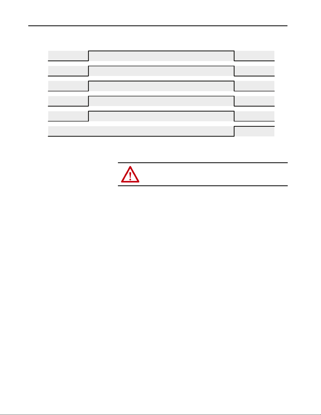
Chapter 4
SO.Reset Request
(1)
SI.Torque Disabled
(3)
SI.Restart Required
(3)
SI.STO Active
(3)
SI. Safety Fault
(1)
STO Activation
(2)
Safety Fault
0x04 = Safety Stop Fault
Tor que Di sab led
Restart Required
Always Required to Reset a Fault
Disable Torque
(1) Safety Output Assembly (2) Safe Stop Function Attribute (3) Safety Input Assembly
Fault C lear ed
Figure 22 - STO with Safety Fault
ATT EN TI ON : In the case of STO activation by a safety fault, the configured
STO Delay time is ignored, and torque is immediately disabled.
Safe Torque Off Stopping Action and Source
In response to an STO activation, the type of stop and the source responsible
for controlling the stop are configurable. These configuration attributes are
defined as:
• STO Stopping Action – Configures what stopping action to perform in
response to a STO activation.
• STO Stopping Action Source – Configures where the stopping action is
performed (drive-based or controller-based).
When STO is activated, the drive control will initiate the selected stop type if:
• The STO Action Source is configured as Drive or
• There is currently not a Standard I/O connection through the
Embedded EtherNet/IP port to the drive control or
• There is currently a Standard I/O connection through the Embedded
EtherNet/IP port to the drive control but it is in Idle mode (the
controller is in program mode)
Otherwise, the controller that owns the Standard I/O connection is expected
to respond when STO is activated. In this case, the configured STO Stopping
Action is ignored, and the stopping logic must be programmed in the
controller that owns the Standard I/O connection.
74 Rockwell Automation Publication 750-UM005C-EN-P - February 2021
Page 75

Chapter 4
If the STO Stopping Action Source is Controller, or the STO Stopping Action
is configured for a non-default value, a STO Delay may need to be specified in
order for the Stopping Action to be completed before torque is disabled.
See the drive's reference manual for information on its supported stop modes.
IMPORTANT You are responsible for providing logic in the controller standard task to
implement a stop action when the STO Action Source is configured as
Controller.
IMPORTANT If STO Delay is zero, there is no time for the drive to complete a stop before
torque is disabled. In that case, the stop action is effectively ‘Coast’ (default).
STO Safety Fault
When the module experiences a STO Fault, the module is placed in the safe
state and the cause of the fault is recorded. If the STO function detects a fault,
it will set the following attributes:
• module:SI.SafetyFault = 1
• module:SI.RestartRequired = 1
•STO Fault Type
• In Standard Control Mode
– Device: P7 [STO Fault Type] = varies depnding on the cause of the
fault. See description of STO Fault Type in Table 105
on page 254.
– Host: P4 [Safety Status] Safety Fault = 1
–Host: P4 [Safety Status] Restart Req = 1
– Host: P5 [Safety Faults] STO Fault = 1
– 755 Port 0: P933 [Start Inhibits], bit 7 = ‘Safety’
755T Port 0: P351 [M Start Inhibits], bit 8 = ‘Safety’
– 755 Port 0: P951 [Last Fault Code] = ‘Safety Brd Flt’
755T Port 0: P610 [Last Fault Code] = ‘Safety Brd Flt’
• In Motion Control Mode
–Axis.SafetyFault = 1
– axis.SafeTorqueOffActiveInhibit = 1
– axis.SafetyFaultStatus = 1
– axis.SafetyResetRequiredStatus = 1
– axis.STOFault = 1
For more information on STO Fault Types and troubleshooting methods, see
Understand Safety Faults on page 199
.
Rockwell Automation Publication 750-UM005C-EN-P - February 2021 75
Page 76

Chapter 4
Connection Idle
(2)
Connection Loss
(1)
SS1 Request
Safety Limit Active
SS1 Activation
SS1 Request
Connection Loss
Safety Limit Active
Connection Idle
Logica l
OR
SS1 Active
(1) Connection Loss Action = SS1
(2) Connection Idle Action = SS1
Safe Stop 1 Function
The Safe Stop 1 (SS1) function signals the configured SS1 Stop Action Source
to initiate a stopping action, then the safety module monitors the stop. When
the Safe Stop 1 is complete, STO is activated and torque is disabled. If the drive
does not complete the stop within the limits that are configured in the Safe
Stop 1 function, an SS1 Fault is annunciated.
Safe Stop 1 Activation
Safe Stop 1 can be initiated by one or more sources:
• SS1 Request – Setting the Safety Output Assembly Tag
(module:SO.SS1Request = 1)
• Limit Active – Reserved for future use
• Connection Loss – Loss of connection to the safety controller
• Connection Idle – Safety controller in program mode
When SS1 is activated, all sources of activation are stored in an attribute as a bit
mask and the attribute can then be read to determine the causes of an SS1
activation. Figure 23
SS1 Activation attribute can be read with explicit messaging (see attribute 289
in Table 18 on page 247
shows the operation of the SS1 activation attribute. The
).
Unlike the STO function, SS1 does not get activated by a safety fault.
Figure 23 - Safe Stop 1 Activation
76 Rockwell Automation Publication 750-UM005C-EN-P - February 2021
Page 77

Chapter 4
Safe Stop 1 Reset
After an SS1 action is complete, the SS1 function must be reset in order to
enable torque. When the STO Function needs to be reset, the following
attribute values are set:
• module:SI.SS1Active = 1
• module:SI.RestartRequired = 1
• In Standard Control Mode:
–Host: P4 [Safety Status] SS1 Active = 1
–Host: P4 [Safety Status] Restart Required = 1
• In Motion Control Mode:
– axis:SS1ActiveStatus = 1
– axis.SafetyResetRequiredStatus = 1
The steps to reset the SS1 function depend on the cause of SS1 activation and
the Restart/Cold Start Type configured in the module.
Connection Loss/Idle SS1 Activation Reset
If the SS1 function is activated by a connection loss/idle event, the connection
must be reestablished and running before the SS1 function can be reset. The
function must be reset based on the configured Cold Start type.
SS1 Automatic Cold Start/Restart Type Operation
If there are no Safety Faults present in the module, the SS1 function can be
reset by a 1→0 transition on the module:SO.SS1Request tag.
SS1 Manual Cold Start/Restart Type Operation
If there are no Safety Faults in the module, the SS1 function can be reset by a
1→0 transition on the module:SO. SS1Request tag then a 0→1 transition on
module:SO.ResetRequest tag.
Rockwell Automation Publication 750-UM005C-EN-P - February 2021 77
Page 78

Chapter 4
Safe Stop 1 Stopping Action and Source
In response to an SS1 activation, the type of stop and the source responsible for
controlling the stop is configurable. These configuration attributes are defined
as:
• SS1 Stopping Action – Configures what stopping action to perform in
response to an SS1 Activation.
• SS1 Stopping Action Source – Configures where the stopping action is
performed (drive-based or controller-based).
When SS1 is activated the drive control will initiate the selected stop type if:
• The SS1 Action Source is configured as Drive
• There is currently not a Standard I/O connection through the
Embedded EtherNet/IP port to the drive control
• There is currently a Standard I/O connection through the Embedded
EtherNet/IP port to the drive control but it is in Idle mode (the
controller is in program mode)
Otherwise, the controller that owns the Standard I/O connection is expected
to respond when SS1 is activated. In this case, the configured SS1 Stopping
Action is ignored, and the stopping logic must be programmed in the
controller that owns the Standard I/O connection.
See the drive's reference manual for information on its supported stop modes.
IMPORTANT You are responsible for providing logic in the controller standard task to
implement a stop action when the SS1 action source is Controller.
Timed Safe Stop 1
A Timed Safe Stop 1 involves initiating motor deceleration and initiating the
STO function after the configured time delay.
Timed Safe Stop 1 Operation
When the module is configured for Timed Safe Stop 1 Mode, the Safe Stop 1
function is initiated by setting the module:SO.SS1Request safety output tag.
This sets the ‘SS1 Request’ bit in the SS1 Activation attribute and sets the
module:SI.SS1Active safety input tag. When the SS1 Active bit is set, the SS1
Stop Action will be executed by the source indicated by the SS1 Stop Action
Source. See Safe Stop 1 Stopping Action and Source
for more information.
The SS1 function waits for the configured SS1 Max Stop Time, then sets the
SS1 Complete flag in the STO Activation attribute, which sets STO Active to
Disable Torque. In Timed Safe Stop 1 mode, speed and deceleration are not
monitored so this mode does not require Safety Feedback. Figure 24
78 Rockwell Automation Publication 750-UM005C-EN-P - February 2021
shows the
Page 79

Chapter 4
0x00
0x01 = SS1 Request
Active
Disable Torque
Tor que Di sab le d
Restart Required
0x02 = SS1 Complete
SS1 Ext Max Stop Time
Velo cit y
(1) Safety Output Assembly
(2) Safe Stop Function Attribute
(3) Safety Input Assembly
SI.RestartRequired
(3)
SI.STOActive
(3)
SI.SS1Active
(3)
SO.SS1Request
(1)
SS1 Activation
(2)
SI.TorqueDisabled
(3)
STO Activation
(2)
0x00
Required if Restart Type = Manual
SI.RequestReset
(1)
Restart Type = Automatic
Restart Type = Manual
0x00
0x00
timing of SS1 status and torque attributes in response to an SS1 activation,
along with the restart type behavior.
Figure 24 - Timed Safe Stop 1
Monitored Safe Stop 1
A Monitored Safe Stop 1 involves monitoring motor feedback deceleration
rate and time, then initiating an STO activation when the motor feedback
speed is below a specified limit.
Monitored Safe Stop 1 Operation
When the module is configured for Monitored Safe Stop 1 Mode, the Safe
Stop 1 function is initiated by setting the module:SO.SS1Request safety output
tag. This sets the ‘SS1 Request’ bit in the SS1 Activation attribute, and also sets
the module:SI.SS1Active safety input tag. When the SS1 Active bit is set, the
SS1 Stop Action will be executed by the configured SS1 Stop Action Source.
See Safe Stop 1 Stopping Action and Source
for more information.
Rockwell Automation Publication 750-UM005C-EN-P - February 2021 79
Page 80

Chapter 4
SS1 Decel Ref Rate
Decel Reference Rate Position Scaling
×
Feedback Resolution
----------------------------------------------------------------------------------------------
–=
Decel Reference Rate =
Decel Reference Speed
1000 Stop Delay
×
----------------------------------------------
If Time Units = Seconds,
SS1 Decel Tolerance
Decel Reference Tolerance Position Scaling
×
Feedback Resolution
-----------------------------------------------------------------------------------------------------------=
If Time Units = Minutes,
SS1 Decel Ref Rate
Decel Reference Rate Position Scaling
×
Feedback Resolution 60
×
------------------------------------------------------------------------------------------
–=
SS1 Standstill Speed
Standstill Speed Position Scaling×
Feedback Resolution
-----------------------------------------------------------------------------------=
If Time Units = Seconds,
If Time Units = Minutes,
SS1 Standstill Speed
Standstill Speed Position Scaling×
Feedback Resolution 60×
-------------------------------------------------------------------------------
=
Where Standstill Speed, Position Scaling, and Feedback Resolution are
user-configured alues.
After the SS1 Active bit is set, the configured SS1 Decel Monitor Delay timer
begins. After the configured Decel Monitor Delay expires, an internal speed
ramp value is computed every time that the encoder is sampled. If the
magnitude of module:SI.FeedbackVelocity exceeds the sum of the internal
ramp plus Decel Speed Tolerance, the SS1 Fault Type attribute is set to
‘Deceleration Rate’ and the SS1 Fault attribute is set to Faulted.
Figure 25
describes the equations that are used for computing the deceleration
reference rate and tolerance.
Figure 25 - SS1 Deceleration Reference Rate and Tolerance Calculation
l
TIP A Configured Decel Reference Rate of 0 disables the ramp check. SS1 will
fault if the drive does not slow to less than the Standstill Speed.
If the magnitude of module:SI.FeedbackVelocity is not less than the configured
Standstill Speed before Max Stop Time expires, the SS1 Fault Type is set to
‘Maximum Time’ and the SS1 Fault attribute is set to ‘Faulted’. Figure 26
describes the equations that are used for computing the standstill speed.
Figure 26 - SS1 Standstill Speed Calculation
80 Rockwell Automation Publication 750-UM005C-EN-P - February 2021
When the magnitude of module:SI.FeedbackVelocity is less than the Standstill
Speed, the SS1 Complete flag in the STO Activation attribute is set, and STO
Active is set. If STO Delay is positive (and SBC Mode = Not Used) or if STO
Page 81

Chapter 4
0x00
0x01 = SS1 Request
SS1 Active
Disable Torque
Tor qu e D isab le d
Restart Required
0x02 = SS1 Complete
SS1 Decel Ref Rate
Vel oci ty
SI.RestartRequired
(3)
SI.STOActive
(3)
SI.SS1Active
(3)
SO.SS1Request
(1)
SS1 Activation
(2)
SI.TorqueDisabled
(3)
STO Activation
(2)
0x00
Required if Restart Type = Manual
SI.RequestReset
(1)
0x00
0x00
Standstill Speed
SS1 Request
SS1
Decel
Monitor
Delay
SS1 Max Stop Time
(1) Safety Output Assembly
(2) Safe Stop Function Attribute
(3) Safety Input Assembly
Restart Type = Automatic
Restart Type = Manual
to SBC Delay is negative (and STO Activates SBC = Linked), then the Torque
Disabled attribute is set after the configured time delay. Otherwise, the Torque
Disabled attribute is set immediately.
Figure 27
shows the timing of the Monitored SS1 operation, along with the
restart type behavior.
Figure 27 - Monitored Safe Stop 1
TIP Speed units are configured by the ‘Position Units’ and ‘Time Units’ AOP
Controls on the Scaling page.
TIP A Configured Decel Reference Rate of 0 disables the ramp check. SS1 will
fault if the drive does not slow to less than the Standstill Speed within Max
Stop Time.
Rockwell Automation Publication 750-UM005C-EN-P - February 2021 81
Page 82

Chapter 4
SS1 Safety Fault
When an SS1 Safety Fault occurs, the STO function is activated immediately
and torque is disabled. Figure 27
fault occurs during SS1 execution. Figure 28
when an SS1 fault is detected.
The ‘Safe State’ of the SS1 function is the Torque Disabled state. If the SS1
function detects a fault, it will set:
• module:SI.SafetyFault = 1
• module:SI.RestartRequired = 1
•SS1 Fault Type
• In Standard Control Mode
– Device: P10 [SS1 Fault Type] = varies depending on the cause of the
fault. See descriptions of faults in Table 105
– Host: P4 [Safety Status] Safety Fault = 1
–Host: P4 [Safety Status] Restart Req = 1
– Host: P5 [Safety Faults] SS1 Fault = 1
– 755 Port 0: P933 [Start Inhibits], bit 7= ‘Safety’
755T Port 0: P351 [M Start Inhibits], bit 8 = ‘Safety’
– 755 Port 0: P951 [Last Fault Code] = ‘Safety Brd Flt’
755T Port 0: P610 [Last Fault Code] = ‘Safety Brd Flt’
describes the timing of attributes when an SS1
describes the operation of SS1
on page 255 .
• In Motion Control Mode
– axis.SafetyFault = 1
– axis.SafeTorqueOffActiveInhibit = 1
– axis.SafetyFaultStatus = 1
– axis.SafetyResetRequiredStatus = 1
– axis.SS1Fault = 1
Clearing a Safety Fault requires correcting the fault condition and a 0→1
transition on Request Reset. For more information on SS1 Safety Faults, see
Understand Safety Faults on page 199
.
82 Rockwell Automation Publication 750-UM005C-EN-P - February 2021
Page 83

Figure 28 - Safe Stop 1 Fault Operation
0x00
0x01 = SS1 Request
SS1 Active
3 = Deceleration Rate
Tor que D is abl ed
Restart Required
Safety Fault
Fault O ccur s
(Feedback Velocity > Expected Velocity)
Vel oci ty
SI.STOActive
(3)
SI.SS1Active
(3)
SO.SS1Request
(1)
SS1 Activation
(2)
SI.TorqueDisabled
(3)
S1.SafetyFault
(1)
0x00
Always Required to Reset a Fault
0x00
0x00
Standstill Speed
SS1 Request
SS1 Max Stop Time
(1) Safety Output Assembly
(2) Safe Stop Function Attribute
(3) Safety Input Assembly
SS1 Max Stop Time
Disable Torque
0x04 = Safety Stop Fault
1 = No Fault
SO.RequestReset
(1)
SI.RestartRequired
(3)
STO Activation
(2)
SS1 Fault Type
(2)
C
o
a
s
t
t
o
S
t
op
Chapter 4
Safe Brake Control Function
The Safe Brake Control function (SBC) function utilizes the module’s safety
outputs to control an electromechanical brake that is attached to the motor.
The SBC function releases the brake to allow motion or engages the brake to
prevent motion.
Safe Brake Control Activation
Safe Brake Control can be initiated by one or more sources:
• SBC Output – Clearing the Safety Output Assembly Tag
(module:SO.SBCOutput = 0)
• STO Active – If STO Activates, SBC is configured as ‘Linked’
• Safe Stop Fault – Any Safety Fault
• Safe Limit Fault – Reserved for future use
Rockwell Automation Publication 750-UM005C-EN-P - February 2021 83
Page 84

Chapter 4
Safety Limit Fault
Safety Stop Fault
SBC Output
STO Active
(1)
SBC Activation
SBC Output
Safety Stop Fault
STO Active
Safety Limit Fault
Logica l
OR
SBC Active
(1) STO Activates SBC = Linked
STO to
SBC Delay
Brake Engaged
Positive Value: D elay = |Value|
Negative Value: Delay = 0
Safety Fault: Delay = 0
When SBC is activated, all sources of activation are stored in an attribute as a
bit mask, and the attribute can then be read to determine the causes of an SBC
activation. Figure 29
shows the operation of the SBC activation attribute. The
SBC Activation attribute can be read with explicit messaging (see attribute 365
in Table 18 on page 247
Figure 29 - Safe Brake Control Activation
.
If the SBC Activation bit mask indicates that only STO Active is the source of
activation, then the STO to SBC Delay is executed. If the activation is not by
STO Active, or other activation bits are also set, the STO to SBC Delay is not
executed and the brake is immediately engaged.
84 Rockwell Automation Publication 750-UM005C-EN-P - February 2021
Safe Brake Control Reset
After the brake is engaged due to an SBC activation, the SBC function must be
reset in order to release the brake. When the SBC function must be reset, the
following attribute values are set:
• module:SI.SBCActive = 1
• module:SI.RestartRequired = 1
• In Standard Control Mode
– Host: P4 [Safety Status] SBCActive = 1
–Host: P4 [Safety Status] Restart Req = 1
• In Motion Control Mode
– axis.SBCActiveStatus= 1
– axis.SafetyResetRequiredStatus = 1
The steps to reset the SBC function depend on the cause of SBC activation
and the Restart/Cold Start Type configured in the module.
Page 85

Chapter 4
Safety Fault SBC Activation Reset
IMPORTANT When the SBC function is activated by a Safety Fault, the cause of the safety
fault must be removed before the SBC function can be reset, regardless of
the configured restart type.
Once the fault is removed, a 0→1 transition on module:SO.ResetRequest tag
will reset the SBC function to the Brake Released state.
SBC Automatic Cold Start/Restart Type Operation
If there are no Safety Faults in the module, the STO function can be reset by a
0→1 transition on the module:SO.SBCOutput tag.
SBC Manual Cold Start/Restart Type Operation
If Restart Type is set to ‘Manual’ and there are no Safety Faults in the module,
the SBC function can be reset by a 0→1 transition on the
module:SO.SBCOutput tag, then a 0→1 transition on
module:SO.ResetRequest tag.
TIP Setting module:SO.SBCOutput = 1 and module:SO.RequestReset = 1 in the
same scan will enable torque.
Safe Brake Control Modes
SBC Mode specifies if the SBC functionality is used and how the safety
outputs controlling the brake operate. The mode also changes the instances of
the CIP objects controlling the safety outputs. The following modes are
supported by the module.
Not Used
In ‘Not Used’ mode, the SBC function will not be used by the application. The
associated safety outputs are not under SBC control, and can be configured
independently. The safety outputs are mapped to the following CIP objects:
• So0: Safety Discrete Output Point Object Instance 1
• So1: Safety Discrete Output Point Object Instance 2
• Safety Dual Channel Output Object Instance 1
Used, No Test Pulses
In ‘Used, No Test Pulses’ mode, the associated safety outputs are not pulse
tested. The associated safety outputs are under SBC control and cannot be
configured independently. The safety outputs are mapped to the following CIP
objects:
• So0: Safety Discrete Output Point Object Instance 3
Rockwell Automation Publication 750-UM005C-EN-P - February 2021 85
Page 86

Chapter 4
• So1: Safety Discrete Output Point Object Instance 4
• Safety Dual Channel Output Object Instance 2
Used, Test Pulses
In ‘Used, Test Pulses’ mode, the associated safety outputs are tested with a
500 µs pulse every 300 ms when the brake is in the released state (outputs
energized). Pulse tests of So0 and So1 outputs are shifted in time, allowing So0
to So1 shorts to be detected. There is no difference in implementation of
Safety Outputs pulse testing in SBC control versus direct control.
In the ‘Used, Test Pluses’ mode, the safety outputs are under SBC control and
cannot be configured independently. The safety outputs are mapped to the
same CIP objects as the ‘Used, No Test Pulses’ mode.
For more information on the pulse testing that is performed by the SBC
function, see Latch Output Error Operation in Single Channel Mode
page 52.
on
IMPORTANT If the Safe Brake Mode is set to ‘Not Used’, then setting the Safety Output tag
module:SO.SBCOutput = 1 sets the SBC Fault and sets the SBC Fault Type to
‘Config’.
IMPORTANT If the Safe Brake Mode is set to ‘Not Used’, then the state of the two safety
outputs So0 and So1 are controlled by Safety Output Assembly tags;
otherwise, the two Safety Outputs are controlled by the Safe Brake Function.
IMPORTANT If the Safe Brake Mode is set to ‘Used’, then the Safety Input Assembly tags
associated with safety outputs will be forced to:
module:SI.Out00Monitor = 0
module:SI.Out01Monitor = 0
module:SI.Out00Status = 0
module:SI.Out01Status = 0
module:SI.Out00Ready = 0
module:SI.Out01Ready = 0
Safe Brake Control Operation
Safe Brake Control (SBC) operation can be activated by the safety output
assembly or by STO.
86 Rockwell Automation Publication 750-UM005C-EN-P - February 2021
Page 87

Chapter 4
Engage Brake
Tor que Enab led
0x01 = SBC Output
Brake Engaged
Restart Required
Required If Restart Type = Manual
Engage Brake
(1) Safety Output A ssembly
(2) Safe Stop Function Attribute
(3) Safety Input Assembly
(4) 24V DC Safety Output
Restart Type = Automatic
Restart Type = Manual
SO.ResetRequest
(1)
SI.BrakeEngaged
(3)
SBC Activation
(2)
SO.SBCOutput
(1)
SI.TorqueDisabled
(3)
So0 and So1
(4)
SI.SBCActive
(3)
Brake Engaged
0x00
SBC Operation when Activated by Safety Output Assembly
When the SBC function is activated by clearing the module:SO.SBCOutput
tag, the associated safety outputs are deenergized, forcing the brake to engage,
and torque is still enabled. Figure 30
the SBC function is executed independently.
Figure 30 - SBC Operation by Safety Output Assembly
shows the timing of SBC attributes when
STO Activates SBC Operation
If the SBC function is configured to link STO and SBC activation, any STO
activation will cause the SBC function to be activated as well. The brake is
engaged (deenergized) by the SBC function when torque is disabled by the
STO function.
If the SBC function is configured to link STO activation to SBC activation,
you can configure an STO to SBC Delay time where:
• STO to SBC Delay > 0 configures a delay between when STO is
activated and the brake is released. Figure 31
• STO to SBC Delay < 0 configures the brake to engage when STO is
activated and delays disabling torque. Figure 32
Rockwell Automation Publication 750-UM005C-EN-P - February 2021 87
describes this operation.
describes this operation.
Page 88

Chapter 4
Disable Torque
Tor que D is abl ed
Engage Brake
Required If Restart Type = Manual
0x02 = STO Active
(1) Safety Output Assembly
(2) Safe Stop Function Attribute
(3) 24V DC Safety Output
(4) Safety Output Assembly
Restart Type = Automatic
Restart Type = Manual
SI.BrakeEngaged
(1)
SI.SBCActive
(1)
SI.TorqueDisabled
(1)
SI. STO Active
(1)
(STO to SBC Delay) > 0
SBC Activation
(2)
Brake Engaged
0x00
So0 and So1
(3)
SO.RequestReset
(4)
Brake Engaged
Disable Torque
Tor que Di sab led
Engage Brake
Required If Restart Type = Manual
0x02 = STO Active
(1) Safety Output Assembly
(2) Safe Stop Function Attribute
(3) Safety Input Assembly
(4) 24V DC Safety Output
(5) Safety Output Assembly
Restart Type = Automatic
Restart Type = Manual
SI.BrakeEngaged
(3)
SI.SBCActive
(3)
SI.TorqueDisabled
(3)
SI. STO Active
(3)
(STO to SBC Delay) <0
SBC Activation
(2)
Brake Engaged
0x00
So0 and So1
(4
SO.RequestReset
(5)
Brake Engaged
Figure 31 - SBC Linked to STO with Positive Delay
Figure 32 - SBC Linked to STO with Negative Delay
88 Rockwell Automation Publication 750-UM005C-EN-P - February 2021
SBC Safety Fault Operation
The operation of SBC under a safety fault condition is dependent on its
configuration. If the SBC function is not configured for use, the SBC function
is not activated when a safety fault occurs. If configured for use, a safety fault
will force the SBC function to the safe state, but the sequence of events leading
Page 89

Chapter 4
Safety Fault
0x04 = Safety Stop Fault
Brake Engaged
(1) Safety Output Assembly (2) Safe Stop Function Attribute (5) Safety Input Assembly
SI.BrakeEngaged
(3)
SBC Activation
(2)
SI.SafetyFault
(1)
SI.SBCActive
(3)
0x00
SI.RestartRequired
(3)
SI.TorqueDisabled
(3)
SO.ResetRequest
(1)
Tor que Di sab le d
Disable Torque
Reset Fault
to the safe state changes. The ‘Safe State’ of the SBC function is the ‘Brake
Engaged’ state.
SBC not Linked to STO Safety Fault Operation
When a safety fault is detected in the module (and the SBC function is
configured to not be linked to STO activation), the SBC function will be
activated with the SBC activation reason being ‘Safety Stop Fault’. The SBC
function can be reset once the safety fault is cleared. Figure 33
timing of SBC and torque attributes in response to a safety fault in this
scenario.
Figure 33 - SBC Operation Under Safety Fault Condition (not linked to STO)
shows the
STO Linked to SBC Safety Fault Operation
When a safety fault is detected in the module and the SBC function is
configured to link STO and SBC activation, the SBC function will be
activated with the SBC activation reason being ‘STO Active’ and ‘Safety Stop
Fault’. The SBC and STO function can be reset once the safety fault is cleared.
Figure 34
fault condition when linked to STO.
Rockwell Automation Publication 750-UM005C-EN-P - February 2021 89
and Figure 35 show the operation of the SBC function under a safety
Page 90

Chapter 4
Safety Fault
0x04 = Safety Stop Fault
Tor que D is abl ed
Always Required to Reset a Fault
Disable Torque
(1) Safe Stop Function Attribute
(2) Safety Input Assembly
(3) 24V DC Safety Output
(4) 2Safety Output Assembly
SI.SBCActive
(2)
SI.TorqueDisabled
(2)
STO Activation
(1)
SI.SafetyFault
(2)
(STO to SBC Delay) >0
SI.STOActive
(2)
Engage Brake
0x00
SBC Activation
(1)
SI.BrakeEngaged
(2)
Brake Engaged
So0 and So1
(3)
SO.RequestReset
(4)
0x06 = STO Active, Safety Stop Fault
Brake Engaged
0x00
Fault Cleared
Safety Fault
0x04 = Safety Stop Fault
Tor que D is abl ed
Always Required to Reset a Fault
Disable Torque
(1) Safe Stop Function Attribute
(2) Safety Input Assembly
(3) 24V DC Safety Output
(4) 2Safety Output Assembly
SI.SBCActive
(1)
SI.TorqueDisabled
(2)
STO Activation
(1)
SI.SafetyFault
(2)
(STO to SBC Delay) <0
SI.STOActive
(2)
Engage Brake
0x00
SBC Activation
(1)
SI.BrakeEngaged
(2)
Brake Engaged
So0 and So1
(3)
SO.RequestReset
(4)
0x06 = STO Active, Safety Stop Fault
Brake Engaged
0x00
Fault Cleared
Figure 34 - SBC Operation under Safety Fault Condition (linked to STO with positive delay)
Figure 35 - SBC Operation under Safety Fault Condition (linked to STO with negative delay)
90 Rockwell Automation Publication 750-UM005C-EN-P - February 2021
Page 91

Chapter 4
SBC Safety Fault
When the module experiences an SBC Fault, the module is placed in the safe
state and the cause of the fault is recorded.
If SBC function detects a fault, it will set:
• module:SI.SafetyFault = 1
• module:SI.RestartRequired = 1
• module:SI.SBCReady = 0
• In Standard Control Mode
– Host P4 [Safety Status] Safety Fault = 1
– Host P4 [Safety Status] Restart Req = 1
– Host P5 [Safety Faults] SBC Fault = 1
• In Motion Control Mode
• axis.SafetyFaultStatus = 1
• axis.SafetyResetRequiredStatus = 1
• axis.SBCFault = 1
Connecting a Safety Brake
For more information on SBC fault types and troubleshooting methods, see
the Understand Safety Faults
The safety brake control function uses the safety outputs So0 and So1 to
control a safety brake.
The design of a safety brake circuit is application-dependent and is based on
the following factors:
• Choice of safety brake for the application
• If the brake provides feedback in the application
• If the application uses single or dual channel
The safety brake function interfaces to the safety brake through the two safety
outputs So0 and So1. So0 and So1 are 24V DC, 1 A sourcing outputs.
Figure 36
Usually the voltage and current rating of the safety brake is much higher than
the 24V DC and 1 A that the safety outputs can directly control. To support
brakes with that require higher voltage and higher current, an interposing
safety relay such as the 700S-CF Safety Control Relay is required.
shows a wiring example for connecting a brake to the module.
chapter beginning on page 199.
Safety brakes typically require a voltage suppression device. Most safety brakes
provide a suppression device as an option or they specify a diode or MOV to
use. Use the recommended suppression devices.
Rockwell Automation Publication 750-UM005C-EN-P - February 2021 91
Page 92

Chapter 4
24V DC
SELV/PELV
Supply
+-
To1
Si2
SC
Si3
To0
NC
So0
SC
So1
Si0
SC
Si1
SC
SP
Tes t O utp ut 1
Safety Input 2
Safety Common
Safety Input 3
Tes t O utp ut 0
not used
Safety Output 0
Safety Common
Safety Output 1
Safety Input 0
Safety Common
Safety Input 1
Safety Common
Safety Power
BR1
M
K1
The drive-based SBC function does not implement checking of brake
feedback; however, the available safety inputs can be used to send the status of
brake feedback to the safety controller that is programmed with a diagnostic
check.
TIP The controller-based SBC instruction does perform a diagnostic check of
brake feedback while drive-based SBC does not. However, drive-based SBC
can be configured to complete a Safe Stop 1 before engaging the brake in
reaction to a Comm Loss or a Comm Idle.
Figure 36 - Safety Brake Wiring
92 Rockwell Automation Publication 750-UM005C-EN-P - February 2021
Page 93

Chapter 5
Controller-based Safety Functions
Use this chapter to become familiar with the GuardLogix® controller-based
Drive Safety instructions and how they interact with PowerFlex® 755/755T
drive products with a 20-750-S4 Integrated Safety Functions option module.
Top ic Pag e
Drive Safety Instructions 93
Pass-through Data Using Standard I/O Mode 96
Pass-through Data Using Integrated Motion 98
SFX Instruction 99
See the GuardLogix Safety Application Instruction Set Reference Manual,
publication 1756-RM095
instructions and TÜV Rheinland certification.
, for more information on the Drive Safety
Drive Safety Instructions
The Drive Safety instructions (see Table 40 on page 94) are designed to work
with the 20-750-S4 option module. They are available in the Studio 5000
Logix Designer® application, version 31.00 or later, in the Drive Safety
instruction element group that is enabled when the Safety Program MainRoutine is open (see Figure 37 on page 94
Controller-based safety functions operate in GuardLogix 5580 or Compact
GuardLogix 5380 controllers and use the EtherNet/IP™ network to
communicate with the safety I/O. Drive Safety instructions use safety
feedback, provided by PowerFlex 755/755T drive products to the Safety Task
of the controller, to perform safe monitoring functions.
).
Rockwell Automation Publication 750-UM005C-EN-P - February 2021 93
Page 94

Chapter 5
Drive Safety Instructions
Drive Safety Tab
Drive Safety Example
Table 40 - Drive Safety Instructions
Safety Instruction Description
Safety Feedback Interface SFX The SFX function scales feedback position into position units and
feedback velocity into position units per time unit. SFX is used with
other Drive Safety instructions.SFX also provides unwind for rotary
applications and position homing.
Safe Stop 1 SS1 The SS1 function monitors the motor deceleration rate within set
limits during motor stopping and provides an indication to initiate
Safe Torque Off (STO) function when the motor speed is below the
specified limit.
Safe Stop 2 SS2 The SS2 function monitors the motor deceleration rate within set
limits during motor stopping and initiates the Safe Operating Stop
(SOS) function when the motor speed is below the specified limit.
Safe Operational Stop SOS The SOS function prevents the motor from deviating more than a
defined amount from the stopped position.
Safely-limited Speed SLS The SLS function prevents the motor from exceeding the specified
speed limit.
Safely-limited Position SLP The SLP function prevents the motor shaft from exceeding the
specified position limits.
Safe Direction SDI The SDI function prevents the motor shaft from moving in the
unintended direction.
Safe Brake Control SBC The SBC function provides safe output signals to control an external
brake.
Figure 37 - Drive Safety Tab and Instructions
94 Rockwell Automation Publication 750-UM005C-EN-P - February 2021
Page 95

Chapter 5
Configurable
Inputs
Inputs
Pass Through
Outputs
Outputs
Before Adding the Safety Instructions
Before adding drive safety instructions to your Logix Designer application, you
must have PowerFlex 755/755T drive products with 20-750-S4 options
installed in your project.
Drive Safety Instruction Example
Drive Safety instructions provide the following information. In this example,
the Safely-limited Speed (SLS) instruction is shown.
Figure 38 - SLS Drive Safety Instruction
Table 41 - Drive Safety Instruction Definitions
Instruction Information Description
Configurable Inputs Safety function parameters that are used to define how the safety function
Inputs • Feedback SFX is the link to the SFX instruction for an axis.
Pass Through Safety Output Assembly Object tags pass safety function status information from
Outputs • Fault Type is the instruction fault code that indicates the type of fault that
Rockwell Automation Publication 750-UM005C-EN-P - February 2021 95
operates.
• Request initiates the safe monitoring function.
• Reset initiates a safety instruction reset.
the Safety Task of the safety controller to the safety instance of the drive module.
The status is made available to the motion controller. In standard I/O mode,
datalinks must also be configured to provide status information to the standard
controller.
occurred.
• Diagnostic Code provides additional details on the fault.
• O1 - Output 1 indicates the status of the instruction. When ON (1), it indicates
that the input conditions are satisfied.
• RR - Reset Required indicates when a reset is needed to restart the instruction
or to clear faults.
• FP - Fault Present indicates whether a fault is present in the instruction.
Page 96

Chapter 5
SLS Active is set high (1).
PowerFlex 755 Drive
Safety
Device
Safety demand initiates
monitoring of the SLS
safety function.
SLS Active status is
sent to the drive.
SLS Active status is passed
to the Standard Task via
Datalinks.
Controller-based Instruction Example
Safety Task Programming
Standard Task Programming
SLS Active Status initiates
change of motion speed.
Pass-through Data Using Standard I/O Mode
The Drive Safety instructions provide safety function monitoring in the safety
task of a controller. Control of the drive is done in the main program within
the standard (main) task of a controller. For the main program to receive safety
status information from the Drive Safety instruction, tag data in the safety
output assembly for the drive module (safety task) is passed to the drive and
then data linked to tags in the main task.
This is especially useful when the user's program is in a separate controller from
the safety program that is in a safety controller. Figure 39
shows how this works
for the SLS instruction.
IMPORTANT Pass-through data is for status information only and does not impact
configured safety functions.
Figure 39 - Pass-through Data Path (Standard I/O Mode)
96 Rockwell Automation Publication 750-UM005C-EN-P - February 2021
SLS Active status and safety faults are passed to the standard task via userconfigured datalinks (inputs) to the following host config parameters in the
Integrated Safety Functions option module:
•P4 [Safety Status]
•P5 [Safety Faults]
TIP Other safety parameters may also need to be data linked depending on your
application.
Page 97

Chapter 5
Table 42 - SLS Tag Information
Safety Output Assembly Tag Axis Tag
module:SO.SLSActive Drive:I.Safet yStatus SLSActive
module:SO.SLSLimit Drive:I.SafetyStatus SLSLimit
module:SO.SLSFault Drive:I.SafetyStatus SLSFault
TIP The words module and drive (italic) in these tag names represent the
module and drive name that is assigned in the Logix Designer application.
The following steps correspond to the activity in Figure 39.
1. Safety device reports a request to the safety zone. Initiates monitoring by
the SLS instruction (Safety Task).
2. SLS Active status is passed to the Standard program (Safety Task to
Standard Task via the drive).
3. The Standard program adjusts the speed of the drive to below the SLS
Active Limit during the Check Delay (Standard Task).
4. If the drive speed exceeds the SLS Active Limit (Safety Task) during SLS
monitoring, the SLS Limit output is set.
– Optionally, a stopping safety function can be initiated within the
safety program.
Rockwell Automation Publication 750-UM005C-EN-P - February 2021 97
Page 98

Chapter 5
SLS Active is set high (1).
PowerFlex 755 Drive
Safety
Device
Safety demand initiates
monitoring of the SLS
safety function.
SLS Active status is
sent to the drive.
SLS Active status is passed
to the Standard Task.
SLS Active Status initiates
change of motion speed.
Controller-based Instruction Example
Safety Task Programming
Standard Task Programming
Pass-through Data Using Integrated Motion
The Drive Safety instructions provide safety function monitoring in the safety
task of the controller. Control of the drive is done in the motion programming
within the standard task of the controller. For the main program to receive
status information from the Drive Safety instruction, tag data in the output
assembly for the drive module (safety task) are passed to the drive and then to
the corresponding tag in the axis structure (standard task).
This is especially useful when the motion program is in a separate controller
from the safety program that is in a safety controller. Figure 40
shows how this
works for the SLS instruction.
IMPORTANT Pass-through data is for status information only and does not impact
configured safety functions.
Figure 40 - Pass-through Data Path
98 Rockwell Automation Publication 750-UM005C-EN-P - February 2021
Table 43 - SLS Tag Information
Safety Output Assembly Tag Axis Tag
module:SO.SLSActive Axis.SLSActiveStatus
module:SO.SLSLimit Axis.SLSLimitStatus
module:SO.SLSFault Axis.SLSFault
TIP The words module and axis (italic) in these tag names represent the module
and axis name that is assigned in the Logix Designer application.
Page 99

Chapter 5
The following steps correspond to the activity in Figure 40.
1. Safety device reports a request to the safety zone.
Initiates monitoring by the SLS instruction (Safety Task).
2. SLS Active status is passed to the motion program (Safety Task to
Standard Task via the drive).
3. The motion program adjusts the speed of the drive to below the SLS
Active Limit during the Check Delay (Standard Task).
4. If the drive speed exceeds the SLS Active Limit (Safety Task) during SLS
monitoring, the SLS Limit output is set.
– Optionally, a stopping safety function can be initiated within the
safety program.
SFX Instruction
The Safety Feedback Interface (SFX) instruction scales feedback position into
position units and feedback velocity into speed units per unit of time.
Feedback position and velocity are read from the safety input assembly and
become inputs to the instruction. The SFX instruction also sets a reference
position from a home input and performs position unwind in rotary
applications. Typically, one SFX instruction is used per safety drive. This
instruction provides the position and velocity feedback that is used by other
safety instructions, also used by the same safety drive.
The PowerFlex 755/755T drive provides safe position and velocity feedback.
Up to SIL 3 PLe safety rating can be achieved by using dual feedback with
velocity and/or position discrepancy checking.
The outputs of the SFX instruction are used as inputs to other Drive safety
instructions. For any drive with an Integrated Safety Functions option module
to execute a controller-based safety function, an SFX instruction is required.
Although the SFX instruction is a safety instruction, it alone does not perform
a safety function.
In Figure 41
instruction during execution of the SS1 safety function.
, the SS1 instruction uses the Actual Speed output from the SFX
Rockwell Automation Publication 750-UM005C-EN-P - February 2021 99
Page 100

Chapter 5
PowerFlex 755/
755T Drive
PowerFlex 755/
755T Drive
Feedback Position
(counts)
Feedba ck Veloci ty
(feedback units/second)
Actual Position
(position units)
Actual Speed
(position units/second
or position units/minute)
Figure 41 - SFX Instruction Feeds Data to SS1 Instruction
SFX Instruction Example
In this SFX example, an encoder has 512 feedback counts per motor revolution
and is scaled for position to have 512 counts per motor revolution.
The SFX instruction scales the applicable safety instructions with feedback
position units from the safety encoder/motor, into position feedback units
used in applicable safety instructions. It also scales feedback velocity units from
the safety encoder/motor into position feedback units per time unit.
Scaling Setup
When configuring the SFX instruction, calculate the value for ‘Position
Scaling’ so that the ‘Actual Position’ and ‘Actual Speed’ output from the
instruction matches the ‘Actual Position’ and ‘Actual Velocity’ in the motion
controller.
Values from ‘Axis Properties>Scaling and Motion Safety>Primary Feedback’
are required to calculate the instruction input.
The Feedback Resolution is determined based on the feedback device and the
Effective Resolution of the feedback. This information is configured on the
‘Module Properties>Motion Safety>Primary Feedback’ category.
100 Rockwell Automation Publication 750-UM005C-EN-P - February 2021
 Loading...