


PowerFlex 750-Series ATEX
Option Module
Catalog Number 20-750-ATEX
User Manual
Original Instructions
PowerFlex 750-Series ATEX Option Module User Manual
Important User Information
Read this document and the documents listed in the additional resources section about installation, configuration, and
operation of this equipment before you install, configure, operate, or maintain this product. Users are required to familiarize
themselves with installation and wiring instructions in addition to requirements of all applicable codes, laws, and standards.
Activities including installation, adjustments, putting into service, use, assembly, disassembly, and maintenance are required to
be carried out by suitably trained personnel in accordance with applicable code of practice.
If this equipment is used in a manner not specified by the manufacturer, the protection provided by the equipment may be
impaired.
In no event will Rockwell Automation, Inc. be responsible or liable for indirect or consequential damages resulting from the use
or application of this equipment.
The examples and diagrams in this manual are included solely for illustrative purposes. Because of the many variables and
requirements associated with any particular installation, Rockwell Automation, Inc. cannot assume responsibility or liability for
actual use based on the examples and diagrams.
No patent liability is assumed by Rockwell Automation, Inc. with respect to use of information, circuits, equipment, or software
described in this manual.
Reproduction of the contents of this manual, in whole or in part, without written permission of Rockwell Automation, Inc., is
prohibited.
Throughout this manual, when necessary, we use notes to make you aware of safety considerations.
WA RN I NG : Identifies information about practices or circumstances that can cause an explosion in a hazardous environment,
which may lead to personal injury or death, property damage, or economic loss.
ATTENTION: Identifies information about practices or circumstances that can lead to personal injury or death, property
damage, or economic loss. Attentions help you identify a hazard, avoid a hazard, and recognize the consequence.
IMPORTANT Identifies information that is critical for successful application and understanding of the product.
Labels may also be on or inside the equipment to provide specific precautions.
SHOCK HAZARD: Labels may be on or inside the equipment, for example, a drive or motor, to alert people that dangerous
voltage may be present.
BURN HAZARD: Labels may be on or inside the equipment, for example, a drive or motor, to alert people that surfaces may
reach dangerous temperatures.
ARC FLASH HAZARD: Labels may be on or inside the equipment, for example, a motor control center, to alert people to potential
Arc Flash. Arc Flash will cause severe injury or death. Wear proper Personal Protective Equipment (PPE). Follow ALL Regulatory
requirements for safe work practices and for Personal Protective Equipment (PPE).
2 Rockwell Automation Publication 750-UM003E-EN-P - August 2020

Table of Contents
Preface
Summary of Changes . . . . . . . . . . . . . . . . . . . . . . . . . . . . . . . . . . . . . . . . . . . 5
Introduction. . . . . . . . . . . . . . . . . . . . . . . . . . . . . . . . . . . . . . . . . . . . . . . . . . . 5
Additional Resources . . . . . . . . . . . . . . . . . . . . . . . . . . . . . . . . . . . . . . . . . . . 6
Chapter 1
Safety Concepts ATEX Directive 2014/34/EU . . . . . . . . . . . . . . . . . . . . . . . . . . . . . . . . . . 7
Motor Requirements . . . . . . . . . . . . . . . . . . . . . . . . . . . . . . . . . . . . . . . . . . . 8
About the PowerFlex 750-Series ATEX Option Module . . . . . . . . . . 9
Using the PowerFlex 750-Series ATEX Option Module
with an
11-series I/O Option Module . . . . . . . . . . . . . . . . . . . . . . . . . . . . . . . 9
Catalog Numbers for ATEX and 11-Series I/O Option
Modules . . . . . . . . . . . . . . . . . . . . . . . . . . . . . . . . . . . . . . . . . . . . . . . . . . 10
Catalog Numbers for Spare Terminal Plugs . . . . . . . . . . . . . . . . . . 10
ATEX System . . . . . . . . . . . . . . . . . . . . . . . . . . . . . . . . . . . . . . . . . . . . . . . . 10
ATEX Function . . . . . . . . . . . . . . . . . . . . . . . . . . . . . . . . . . . . . . . . . . . . . . 11
Thermostat Trip . . . . . . . . . . . . . . . . . . . . . . . . . . . . . . . . . . . . . . . . . . 11
Positive Temperature Coefficient (PTC) Trip . . . . . . . . . . . . . . . 11
Safe State . . . . . . . . . . . . . . . . . . . . . . . . . . . . . . . . . . . . . . . . . . . . . . . . . . . . . 12
Hardware Fault Tolerance . . . . . . . . . . . . . . . . . . . . . . . . . . . . . . . . . . . . . 12
Safety Reaction Time. . . . . . . . . . . . . . . . . . . . . . . . . . . . . . . . . . . . . . . . . . 13
Contact Information If Safety Option Failure Occurs . . . . . . . . . . . . 13
Chapter 2
Installation and Wiring Perform a Risk Assessment of the Operational Environment. . . . . . 15
Perform a Safety Analysis of the Motor. . . . . . . . . . . . . . . . . . . . . . . . . . 16
Remove Power to the System. . . . . . . . . . . . . . . . . . . . . . . . . . . . . . . . . . . 16
Access the Control Pod . . . . . . . . . . . . . . . . . . . . . . . . . . . . . . . . . . . . . . . . 16
Configure the Hardware. . . . . . . . . . . . . . . . . . . . . . . . . . . . . . . . . . . . . . . 18
S1 Switch Location . . . . . . . . . . . . . . . . . . . . . . . . . . . . . . . . . . . . . . . . 18
Safety Enable Jumper Locations . . . . . . . . . . . . . . . . . . . . . . . . . . . . 19
ATEX Option Module and 11-Series I/O Option Module
without a Safety Option Module. . . . . . . . . . . . . . . . . . . . . . . . . . . . 20
ATEX Option Module and 11-Series I/O Option Module w
ith a Safety Option Module . . . . . . . . . . . . . . . . . . . . . . . . . . . . . . . . 21
Assemble the ATEX and 11-Series I/O Option Modules . . . . . 23
Connect the Thermal Sensor Wires. . . . . . . . . . . . . . . . . . . . . . . . . . . . . 24
Cabling Requirements . . . . . . . . . . . . . . . . . . . . . . . . . . . . . . . . . . . . . 24
Installation Requirements . . . . . . . . . . . . . . . . . . . . . . . . . . . . . . . . . . 25
Install the ATEX Option Module Assembly. . . . . . . . . . . . . . . . . . . . . 25
PowerFlex 750-Series Safe Torque Off Option Wiring . . . . . . . . . . . 27
Safe Speed Monitor Option Wiring. . . . . . . . . . . . . . . . . . . . . . . . . . . . . 28
Integrated Safety - Safe Torque Off Option Module. . . . . . . . . . . . . . 29
PowerFlex 755/755T Integrated Safety Functions Option M
odule. . . . . . . . . . . . . . . . . . . . . . . . . . . . . . . . . . . . . . . . . . . . . . . . . . . . . . . . . 30
Rockwell Automation Publication 750-UM003E-EN-P - August 2020 3

Table of Contents
Reset the Drive after an SSM Fault Detection. . . . . . . . . . . . . . . . . . . . 30
Interface Without a Safety Option. . . . . . . . . . . . . . . . . . . . . . . . . . . . . . 30
Chapter 3
Verify Operation Description of Functionality . . . . . . . . . . . . . . . . . . . . . . . . . . . . . . . . . . . 31
Motors with Thermostatic Switches . . . . . . . . . . . . . . . . . . . . . . . . . . . . 32
Functional Proof Testing for Systems with Thermostat
Contacts. . . . . . . . . . . . . . . . . . . . . . . . . . . . . . . . . . . . . . . . . . . . . . . . . . 32
Motors with Positive Temperature Coefficient (PTC) Devices. . . . 33
Functional Proof Testing for Systems with PTC Devices. . . . . . 33
Functional Proof Testing without a Test Fixture. . . . . . . . . . . . . . . . . 34
Chapter 4
ATEX Monitoring Parameter 41 [ATEX Sts]. . . . . . . . . . . . . . . . . . . . . . . . . . . . . . . . . . . . . . 37
ATEX Fault Descriptions. . . . . . . . . . . . . . . . . . . . . . . . . . . . . . . . . . . . . . 38
ATEX Configuration Errors . . . . . . . . . . . . . . . . . . . . . . . . . . . . . . . . . . . 38
Restart the Drive after an Over-temperature Fault . . . . . . . . . . . . . . . 39
Specifications and
Certifications
Appendix A
General Specifications . . . . . . . . . . . . . . . . . . . . . . . . . . . . . . . . . . . . . . . . . 41
11-Series I/O Option Module Terminal Block Specifications . . . . . 41
Safety Data . . . . . . . . . . . . . . . . . . . . . . . . . . . . . . . . . . . . . . . . . . . . . . . . . . . 42
Environmental Specifications . . . . . . . . . . . . . . . . . . . . . . . . . . . . . . . . . . 42
Certifications . . . . . . . . . . . . . . . . . . . . . . . . . . . . . . . . . . . . . . . . . . . . . . . . . 43
Index
. . . . . . . . . . . . . . . . . . . . . . . . . . . . . . . . . . . . . . . . . . . . . . . . . . . . . . . . 45
4 Rockwell Automation Publication 750-UM003E-EN-P - August 2020

Preface
Summary of Changes
This manual contains new and updated information as indicated in the following
table.
Top ic Pag e
Updated the Introduction to this manual in the Preface. 5
Updated and added model numbers to the About the PowerFlex 750-Series ATEX Option Module
introduction in Chapter 1.
Added Using the PowerFlex 750-Series ATEX Option Module with an 11-series I/O Option Module, to
Chapter 1.
Added Remove Power to the System section. 16
Updated Access the Control Pod instructions. 16
Added Integrated Safety - Safe Torque Off (catalog number 20-750-S3) and Integrated Safety Functions
(catalog number 20-750-S4 to Configure the Hardware section of Chapter 2.
Added Integrated Safety - Safe Torque Off (catalog number 20-750-S3) and Integrated Safety Functions
(catalog number 20-750-S4 to ATEX Option Module and 11-Series I/O Option Module with a Safety
Option Module section of Chapter 2.
Changed ATTENTION statement in Install the ATEX Option Module Assembly to match the Remove
Power to the System statement in the Installation and Wiring chapter.
Added Integrated Safety - Safe Torque Off Option Module sec tion to Chapter 2. 29
Added PowerFlex 755/755T Integrated Safety Functions Option Module section to Chapter 2. 30
Changed ATTENTION statement in Functional Proof Testing without a Test Fixture section to match the
Remove Power to the System statement in the Installation and Wiring chapter.
Revised the title of PFD and PFH for 20-year Proof Test Interval for All PowerFlex 753/755 and
PowerFlex 755T Drives table to show that the safety data applies to all PowerFlex 753/755 and
PowerFlex 755T drives.
Added an Important statement regarding protection for products with a safety function installed. 43
9
9
18
21
25
34
42
Introduction
Use this manual if you are responsible for designing, installing, configuring, or
troubleshooting applications that use the PowerFlex 750-Series ATEX option
module. The 20-750-ATEX option module applies to the following PowerFlex
750-Series drives:
• PowerFlex 755TL low harmonic, non-regenerative drives
• PowerFlex 755TR regenerative drives
• PowerFlex 755TM drive systems with regenerative bus-supplies and
common-bus inverters
• PowerFlex 755 AC drives
• PowerFlex 753 AC drives
Throughout this manual, PowerFlex 755T drive products are used to refer to
PowerFlex 755TL drives, PowerFlex 755TR drives, and PowerFlex 755TM drive
systems.
IMPORTANT Read and understand this user manual before you begin to design and
install your ATEX system.
Rockwell Automation Publication 750-UM003E-EN-P - August 2020 5
Preface
Additional Resources
These documents contain additional information concerning related products
from Rockwell Automation.
Resource Description
PowerFlex 750-Series Products with TotalFORCE™ Control Installation Instructions, publication 750-IN100 Provides the basic steps to install PowerFlex 755TL low harmonic
PowerFlex 755TM IP00 Open Type Kits Installation Instructions, publication 750-IN101 Provides instructions to i nstall IP00 Open Type kits in user-
PowerFlex 750-Series AC Drives Installation Instructions, publication 750-IN001
PowerFlex Drives with TotalFORCE Control Programming Manual, publication 750-PM100
PowerFlex 750-Series AC Drives Programming Manual, publication 750-PM001
PowerFlex 750-Series AC Drives Technical Data, publication 750-TD001 Provides detailed information on:
PowerFlex 750-Series Products with TotalFORCE Control Technical Data, publication 750-TD100
PowerFlex 755TM IP00 Open Type Kits Technical Data, publication 750-TD101 Provides detailed information on:
PowerFlex 750-Series Safe Speed Monitor Option Module Safety Reference Manual, publication 750-RM001 Provides information for the Safe Speed Monitor option (Cat. No.
PowerFlex 750-Series Safe Torque Off User Manual, publication 750-UM002 Provides information for the Safe Torque Off option (Cat. No.
PowerFlex 755/755T Integrated Safety - Safe Torque Off Option Module User Manual, publication 750-UM004
PowerFlex 755/755T Integrated Safety Functions Option Module, publication 750-UM005 Provides information for the Integrated Safety Functions Option
Industrial Automation Wiring and Grounding Guidelines, publication 1770-4.1 Provides general guidelines for installing a Rockwell Automation
Product Certifications website, http://rok.auto/certifications
Provides declarations of conformity, certificates, and other
Provides the basic steps to install PowerFlex 750-Series AC drives.
drives, PowerFlex 755TR regenerative drives, and PowerFlex
755TM drive systems.
supplied enclosures.
Provides detailed information on:
• I/O, control, and feedback options
• Parameters and programming
• Faults, alarms, and troubleshooting
• Drive and bus supply specifications
• Option specifications
• Fuse and circuit breaker ratings
•Kit selection
• Kit ratings and specifications
• Option specifications
20-750-S1) that can be used as a component in a safety control
system.
20-750-S) that can be used as a component in a safety control
system.
Provides information for the Integrated Safety - Safe Torque Off
Option Module (Cat. No. 20-750-S3) that can be used as a
component in a safety control system.
Module (Cat. No. 20-750-S4) that can be used as a component in a
safety control system.
industrial system.
certification details.
You can view or download publications at rok.auto/literature
6 Rockwell Automation Publication 750-UM003E-EN-P - August 2020
.

Safety Concepts
Top ic Pag e
ATEX Directive 2014/34/EU 7
Motor Requirements 8
ATEX System 10
ATEX Function 11
Safe State 12
Hardware Fault Tolerance 12
Safety Reaction Time 13
Contact Information If Safety Option Failure Occurs 13
Chapter 1
ATEX Directive 2014/34/EU
The PowerFlex® ATEX option module that is installed in a PowerFlex 750-Series
drive or PowerFlex 755T drive products and equipped with an 11-Series I/O
option module provides an ATEX-compliant safety function. This ATEXcompliant function provides a safe turn-off for equipment that is installed in a
potentially explosive atmosphere according to 2014/34/EU.
The PowerFlex 750-Series drives and PowerFlex 755T drive products, together
with the ATEX and 11-Series I/O option modules, are compliant safety devices
under the ATEX directive 2014/34/EU, and satisfy requirements for use in
Group II, Category 2, (GD) applications with ATEX approved motors as
described here:
• Group II – The motor is installed in a potentially explosive atmosphere
that is not in a mine.
• Category 2 – The motor is likely to be exposed to an explosive atmosphere.
A high level of protection is required.
• GD – The explosive atmosphere consists of a mixture of (G) gas vapors
and (D) dust that can cause an explosion.
Certification of the drive for the ATEX group and category on its nameplate is
based on installation, operation, and maintenance according to these items:
•This user manual
• The requirements in the drive user manual and installation instructions
•The instruction manual for the motor
Rockwell Automation Publication 750-UM003E-EN-P - August 2020 7
Chapter 1
ATT EN TI ON : Follow all procedures in the standard installation and user
manuals for the ATEX-certified drive with an ATEX-certified motor. You must
also follow all additional instructions in this PowerFlex 750-Series ATEX
Option Module User Manual. Equipment damage and/or personal injury can
result if all additional instructions in this user manual are not followed.
Motor Requirements
• The motor must be manufactured under the guidelines of the ATEX
directive 2014/34/EU. The motor must be installed, operated, and
maintained according to the instructions of the motor manufacturer.
• Only motors with nameplates that are marked for use on an inverter power
source, and labeled for specific hazardous areas, can be used in hazardous
areas on inverter (variable frequency) power.
• When the motor is rated ATEX Group II, Category 2 for use in gas
environments (category 2G), the motor must be of flameproof
construction, EEx d (according to EN 50018) or Ex d (according to
EN 60079-1 or IEC 60079-1). Group II motors are marked with a
temperature or a temperature code.
• When the motor is rated ATEX Group II, Category 2 for use in dust
environments (category 2D), you must protect the motor with an
enclosure (according to EN 50281-1-1, or according to
IEC 61241-1: Ex tD). Group II motors are marked with a temperature.
• The motor over-temperature signal is supplied to the drive by one of two
methods:
– A normally closed contact (open during over temperature condition)
compatible with the digital (logic) input circuitry of the drive. If
multiple sensors are required in the motor, the connection at the drive
must be the result of all required contacts that are wired in series.
– A positive temperature coefficient (PTC) type of thermal sensor. See
Appendix A
for specifications.
•See all product markings for additional cautions.
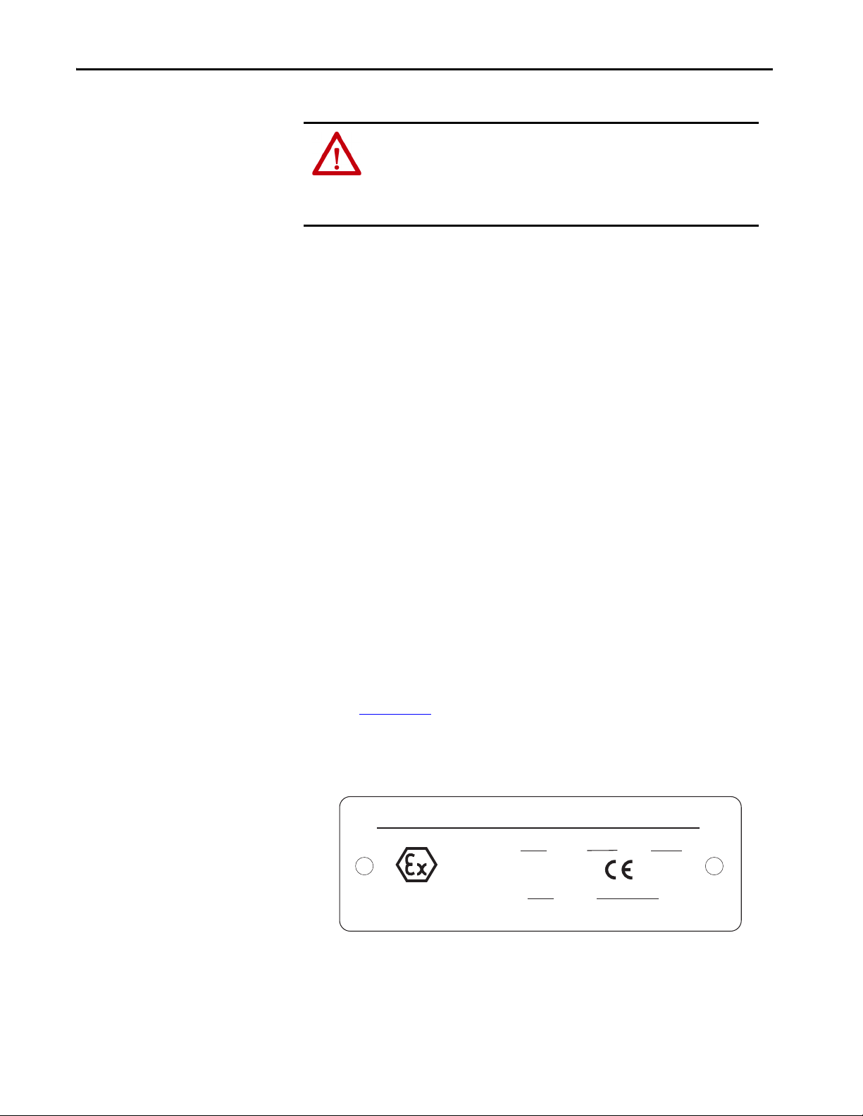
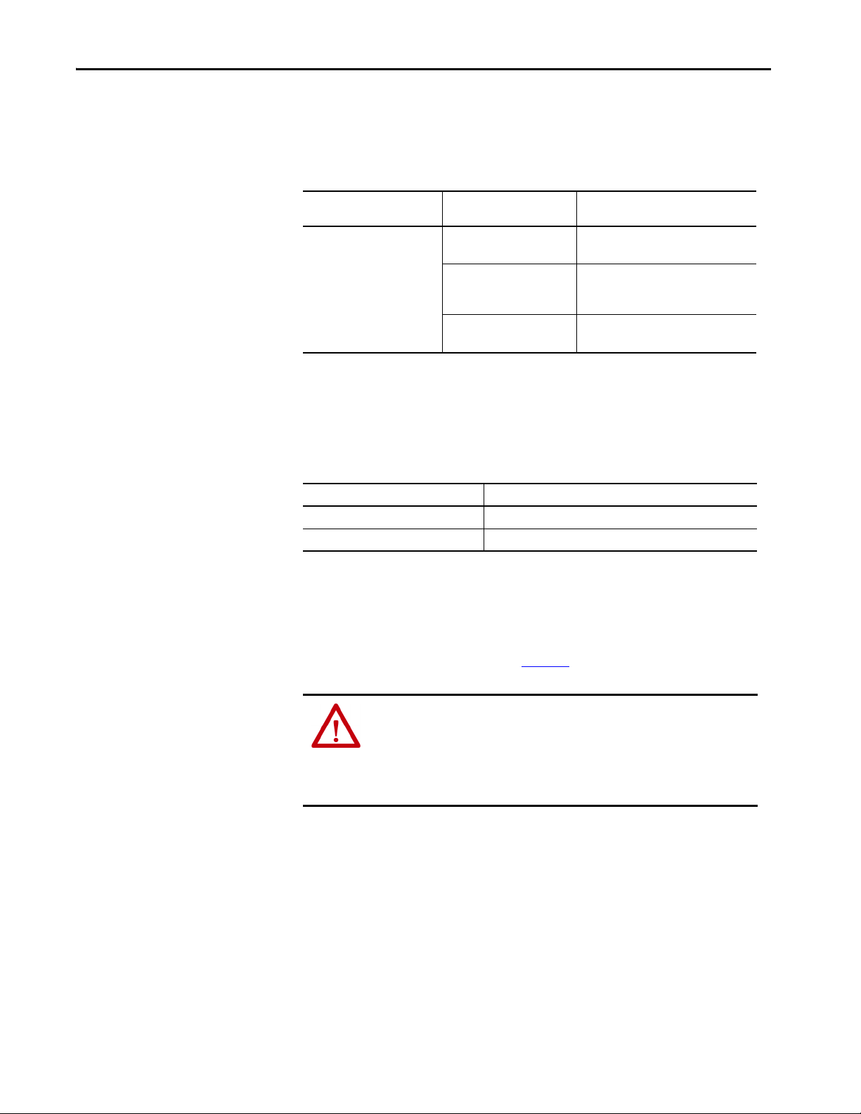
• Typical motor markings are contained on a motor certification nameplate
similar to the sample here.
FLAMEPROOF Exd ENCLOSURE
EExd I/IIB Tamb C to C
II 2 G/D
I M2 Sira ATEX
MFG. BY ROCKWELL AUTOMATION
8 Rockwell Automation Publication 750-UM003E-EN-P - August 2020
0035
Chapter 1
About the PowerFlex 750-Series ATEX Option Module
The PowerFlex ATEX option module and the 11-Series I/O option module for
PowerFlex 750-Series AC drives and PowerFlex 755T drive products are safety
system components of the equipment and protective systems. The option
modules are intended for equipment that is used in potentially explosive
atmospheres (ATEX). Perform a risk assessment and safety analysis of the
operating atmosphere and the ATEX system components before you begin this
ATE X i ns ta lla ti on :
• PowerFlex 750-Series drive
• PowerFlex 755TL low harmonic drives
• PowerFlex 755TR regenerative drives
• PowerFlex 755TM drive systems
• Motor
•ATEX option module
• 11-Series I/O option module
(1)
(1)
(1)
Using the PowerFlex 750-Series ATEX Option Module with an 11-series I/O Option Module
The ATEX option module with the 11-Series I/O option module enables a
PowerFlex 750-Series drive and PowerFlex 755T drive products to be used in
ATEX installations. The ATEX option module helps to reduce the risk of
explosion due to an over-temperature condition in an ATEX approved motor. In
an ATEX installation, the motor is installed in a potentially explosive
atmosphere, while the drive is installed outside of the potentially explosive
atmosphere. See Figure 1
.
WARNING: Risk of Explosion.
Do not install the PowerFlex 750-Series drive or PowerFlex 755T drive products
in a potentially explosive atmosphere.
A drive that is installed in a potentially explosive atmosphere can cause an
explosion.
(1) Throughout this manual, the PowerFlex 755TL low harmonic drives, PowerFlex 755TR regenerative drives, and PowerFlex 755TM
drive systems are also referred to as PowerFlex 755T drive products.
Rockwell Automation Publication 750-UM003E-EN-P - August 2020 9
Chapter 1
Catalog Numbers for ATEX and 11-Series I/O Option Modules
This table lists the catalog numbers for the ATEX option module and the
compatible 11-Series I/O option modules.
ATEX System
ATEX Option Module Cat. No. 11-Series I/O Option Module
Cat. No.
20-750-1132D-2R 115V AC digital input
20-750-1133C-1R2T 24V DC digital input
20-750-ATEX
20-750-1132C-2R 24V DC digital input
Description
Two relay outputs, digital
Two transistor outputs, one relay output,
digital
Two relay outputs, digital
Catalog Numbers for Spare Terminal Plugs
This table contains the catalog numbers for the 11-Series I/O option module
spare terminal plug kits.
Cat. No. Spare Terminal Plug Kit
SK-R1-SCRWTB-EIO Screw-down terminal plugs spare kit (set of three)
SK-R1-SPRGTB-EIO Spring-clamp terminal plugs spare kit (set of three)
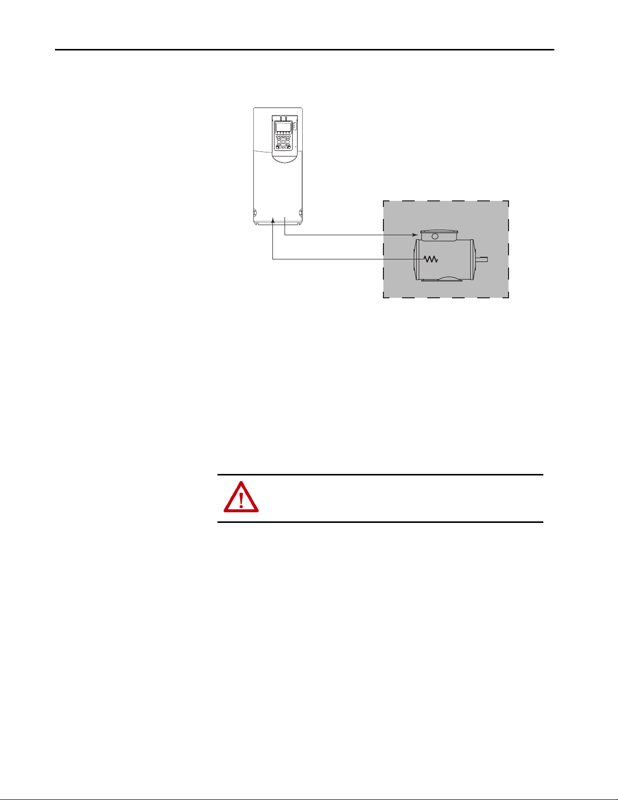
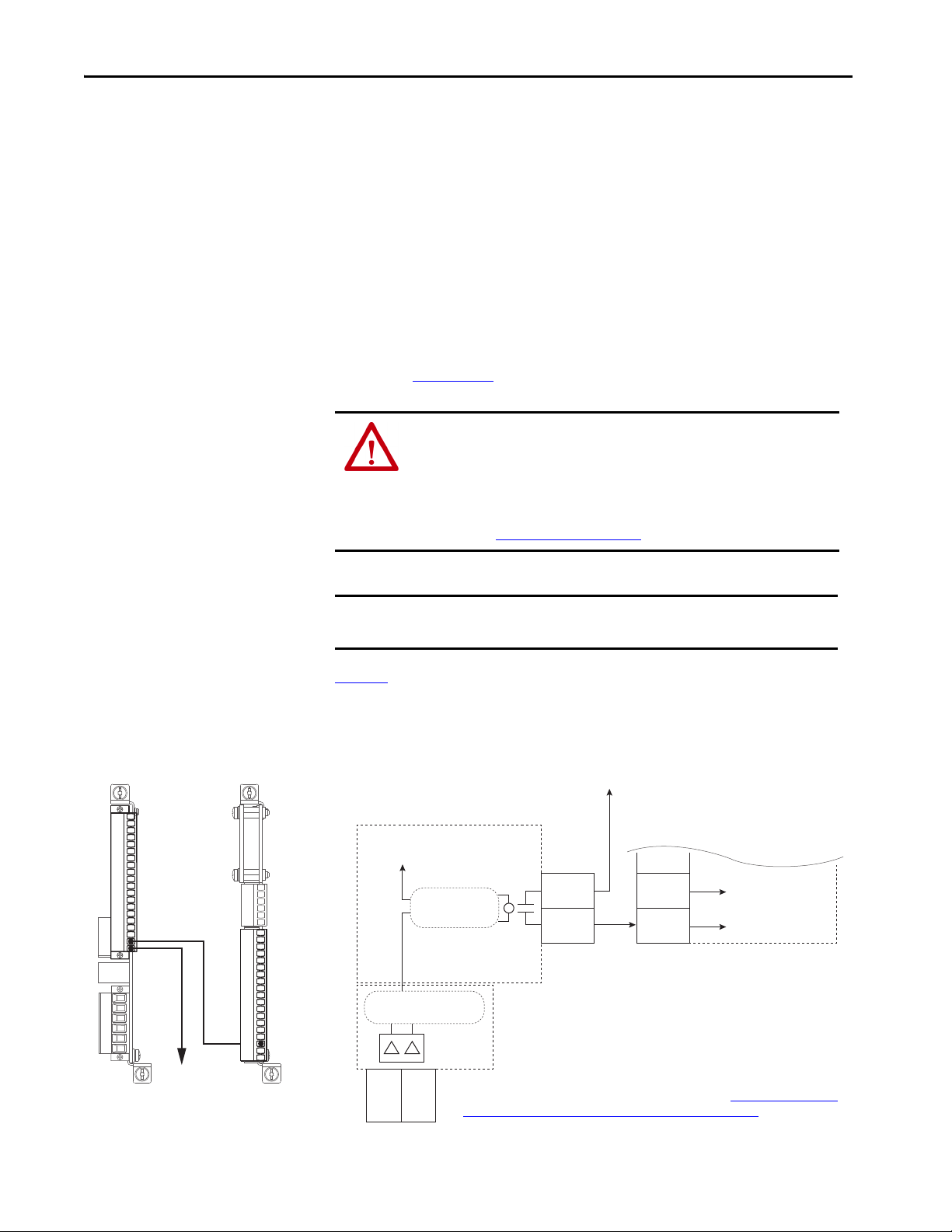
The overall system includes an ATEX certified motor that is installed in a
potentially explosive atmosphere. The motor is equipped with a thermal sensor
that is connected to the ATEX option input. Do not install the drive in a
potentially explosive atmosphere. See Figure 1
.
WARNING: Risk of Explosion.
Do not install the PowerFlex 750-Series drive or PowerFlex 755T drive products
in a potentially explosive atmosphere.
A drive that is installed in a potentially explosive atmosphere can cause an
explosion.
10 Rockwell Automation Publication 750-UM003E-EN-P - August 2020
Chapter 1
PowerFlex 750-Series Drive or PowerFlex 755T drive products (750-Series drive shown)
Power to the Motor
Thermal Sensor Input to the Drive
Poten tially Expl osive Atmosp here
ATEX Certified Motor
Figure 1 - Basic ATEX Application
The ATEX option module monitors the thermal sensor in the motor. When the
thermal sensor reaches its trip point, the drive initiates a Safe Torque Off function
and removes torque-producing power from the motor. The ATEX safety
function has a safety integration level (SIL) capability limit of 1 according to
IEC 61508.
ATEX Function
The PowerFlex 750-Series ATEX option module can be configured to support
ATEX certified motors that are equipped with either a thermostat or a PTC-type
thermal sensor.
Thermostat Trip
When the circuit is configured to trip with a thermostat, the ATEX option
module supports a normally closed, dry-contact thermostat. The safe-off
function initiates when the ATEX option module detects that the contact is
open. This trip can be the result of a broken wire, or an over-temperature
condition in the motor.
Positive Temperature Coefficient (PTC) Trip
When the circuit is configured to trip with a PTC-type thermal sensor, the
ATEX option module supports sensors with characteristics according to
DIN 44081/DIN 440. The ‘Mark A’ measuring circuit on the ATEX option
ATT EN TI ON : Risk of electric shock. If a motor insulation fault occurs, high
voltage can be present at the ATEX terminal block and wiring. Be sure that all
drive covers are installed when power is applied to the drive.
Rockwell Automation Publication 750-UM003E-EN-P - August 2020 11
Chapter 1
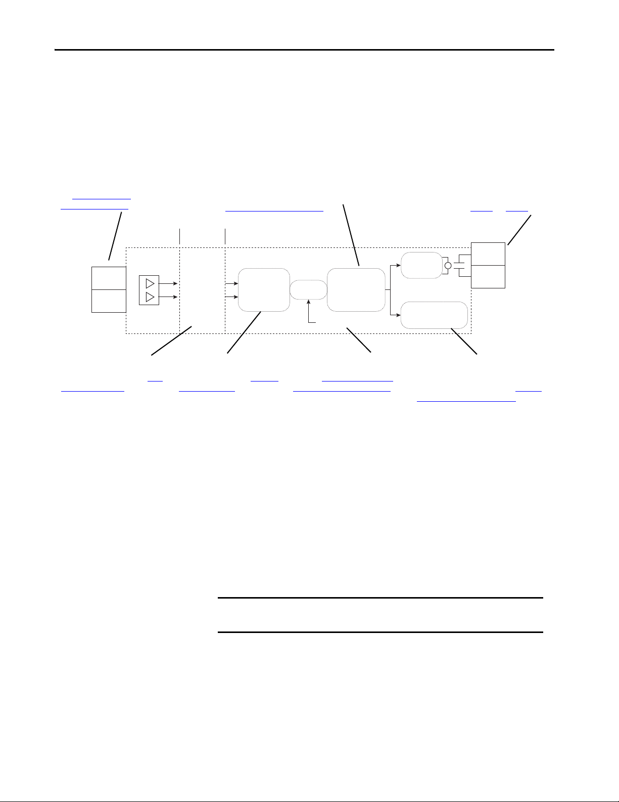
ATEX+
ATEX–
High Voltage
Possible
Isolation Safe Low Voltage
EnC
EnNOThermal
Sensor Type
Switch
Safety
Configuration
Switch
Latch
Relay Driver
Safe Shutdown
Signal
Reset Signal
Or
Field wiring to thermal sensor.
See Connect the Thermal
Sensor Wires on page 24.
Safety configuration switch to configure the
safety path for use with a safety option. See
Configure the Hardware on page 18.
Terminals EnC and EnNO must be wired correctly
when a safety option is present in the drive. See the
important statements on page 27 and page 28.
ATEX trip signals pass through an
isolation barrier to protect the drive
in a motor insulation fault. See ATEX
Monitoring on page 37.
Thermal sensor-type switch selects
between PTC and thermostatictype thermal sensors. See S1 Switch
Location on pa ge 18.
An ATEX trip latches the drive into a
safe state until a reset sequence takes
place. See Restart the Drive after an
Over-temperature Fault on page 39.
For installations that do not have the Safe
Torque Off or Safe Speed Monitor safety options
present, the ATEX safety function uses the
safety signal on the backplane. See Interface
Without a Safety Option on page 30.
module is designed in accordance to IEC 60947-8 or EN 60947-8. This circuit
trips when the motor temperature has reached its trip point, or an open-wire/
short-circuit condition is detected in the sensor circuit.
Loss of voltage to the measuring circuit also initiates the safe-off function. The
ATEX option module internally sources this voltage.
Figure 2 - ATEX Circuitry
Safe State
Hardware Fault Tolerance
The safe state includes all operation that occurs outside of the other monitoring
and stopping behavior that is defined as part of the ATEX option module. The
ATEX safety function, as provided by the ATEX option module, places the drive
in a safe state by removing the power from the gate firing circuits of the output
power devices (IGBTs).
Hardware fault tolerance is the minimum number of faults that can cause a loss of
the safety function as defined by EN 61800-5-2 and IEC 61508 part 2. The
overall ATEX function has a hardware fault tolerance of zero.
IMPORTANT If one fault occurs in the safety path, the safety function can become
compromised.
12 Rockwell Automation Publication 750-UM003E-EN-P - August 2020

Chapter 1
Safety Reaction Time
Contact Information If Safety Option Failure Occurs
The safety reaction time is the amount of time from a safety-related event as
input to the system until the system is in the safe state.
The safety reaction time from an input signal trigger to the initiation of the
ATE X s af et y fun ct ion .
Table 1 - Safety Reaction Time
Drive Safety Reaction Time
PowerFlex 753 drives
PowerFlex 755 drives
PowerFlex 755TL low harmonic drives
PowerFlex 755TR regenerative drives
PowerFlex 755TM drive systems
If you experience a failure with any safety-certified device, contact your local
Allen-Bradley distributor to do the following:
• Return the device to Rockwell Automation so the failure is appropriately
logged for the catalog number that is affected and a record is made of the
failure.
• Request a failure analysis (if necessary) to determine the probable cause of
the failure.
30 ms (max)
Rockwell Automation Publication 750-UM003E-EN-P - August 2020 13

Chapter 1
Notes:
14 Rockwell Automation Publication 750-UM003E-EN-P - August 2020
Installation and Wiring
Top ic P age
Perform a Risk Assessment of the Operational Environment 15
Perform a Safety Analysis of the Motor 16
Remove Power to the System 16
Access t he Control Pod 16
Configure the Hardware 18
Connect the Thermal Sensor Wires 24
Install the ATEX Option Module Assembly 25
PowerFlex 750-Series Safe Torque Off Option Wiring 27
Safe Speed Monitor Option Wiring 28
Integrated Safety - Safe Torque Off Option Module 29
PowerFlex 755/755T Integrated Safety Functions Option
Module
Reset the Drive after an SSM Fault Detection 30
Interface Without a Safety Option 30
Chapter 2
30
Perform a Risk Assessment of the Operational Environment
You must follow the installation steps that are described in this installation and
wiring section. The PowerFlex® 750-Series ATEX option module with an
11-Series I/O module is part of an ATEX safety control system.
ATT EN TI ON : Only qualified personnel familiar with adjustable frequency AC
drives and associated machinery can plan or implement the installation,
startup, and subsequent maintenance of the system. Failure to comply can
result in personal injury and/or equipment damage.
ATT EN TI ON : The following information is a guide for proper installation.
Rockwell Automation does not assume responsibility for the compliance or
the noncompliance to any code, national, local, or otherwise, for the proper
installation of this equipment. Personal injury and/or equipment damage
can occur if codes are ignored during installation.
Before you begin the installation, perform a risk assessment to compare the
ATEX option specifications with the potentially explosive atmosphere where you
want to install the system. See Safety Concepts
on page 7.
Rockwell Automation Publication 750-UM003E-EN-P - August 2020 15
Chapter 2
Perform a Safety Analysis of the Motor
Remove Power to the System
The ATEX safety system includes the thermal sensor in the motor and the wiring
to the ATEX daughter card. Ve ri fy O pera tio n on pa ge 3 1
functional tests of the system from the input to the ATEX daughter card, but
these tests do not verify the thermal sensor response or the wiring from the
motor. Follow the recommendations of the motor manufacturer for safe use of
the motor in ATEX installations and possible functional test procedures.
Before performing any work on the drive, remove all power to the system.
ATT EN TI ON :
• Electric Shock Hazard. Verify that all sources of AC and DC power are deenergized and locked out or tagged out in accordance with the requirements
of ANSI/NFPA 70E, Part II.
• To avoid an electric shock hazard, verify that the voltage on the bus
capacitors has discharged before performing any work on the drive. Measure
the DC bus voltage at the +DC and -DC terminals or test points. The voltage
must be zero.
For the location of the terminal block and test point sockets, see the manual for
your drive:
• PowerFlex 750-Series AC Drives Installation Instructions,
publication 750-IN001
• PowerFlex 750-Series Products with TotalFORCE Control Installation
Instructions, publication 750-IN100
• PowerFlex 755TM IP00 Open Type Kits Installation Instructions,
publication 750-IN101
.
.
.
gives methods for
Access the Control Pod
16 Rockwell Automation Publication 750-UM003E-EN-P - August 2020
The option module is installed in the drive control pod. Different drives have
different ways to access the control pod.
To access the control pod, follow these steps.
1. Open the door or remove the cover.
2. Loosen the retention screw on the HIM cradle.

3. Lift the cradle until the latch engages.
Panel-mo unted D rives
Drives in Cabinet Enclosures
Chapter 2
See the installation instructions for your drive for more information.
Rockwell Automation Publication 750-UM003E-EN-P - August 2020 17

Chapter 2
In this diagram, the ATEX option module is
shown without the insulation wrapper.
Do not remove the insulation wrapper
from the ATEX option module.
Configure the Hardware
The ATEX option module can be used in two different configurations:
• ATEX option module and 11-Series I/O option module that is used
without an additional safety option module. See page 20
.
• ATEX option module and 11-Series I/O option module that is used with
an additional safety option module, including :
– PowerFlex 750-Series Safe Torque Off (catalog number 20-750-S)
– PowerFlex 750-Series Safe Speed Monitor (catalog number 20-750-S1)
option module
– PowerFlex 755/755T Integrated Safety - Safe Torque Off (catalog
number 20-750-S3)
– PowerFlex 755/755T Integrated Safety Functions (catalog number 20-
750-S4)
•See page 21
for additional information.
S1 Switch Location
ATT EN TI ON : Hazard of electric shock exists. Do not remove the insulation
wrapper from the ATEX option module. Removal of the insulation wrapper
can cause an electric shock hazard, and can cause damage to the drive.
See Figure 3 for the location of the S1switches on the ATEX option module:
• S1-1 is the safety configuration switch.
• S1-2 is the thermal sensor switch.
Figure 3 - ATEX Option Module S1 Switch Location
S1-2
S1-1
18 Rockwell Automation Publication 750-UM003E-EN-P - August 2020

Chapter 2
PowerFlex 753 Drive
PowerFlex 755 Drive
PowerFlex 755T Drive Products
Safety Enable Jumper Locations
See Figure 4 for the location of the safety enable jumper on the main control
board of the PowerFlex 750-Series drives and 755T drive products.
IMPORTANT PowerFlex 755 floor mount Frame 8 drives and larger do not have a safety
enable jumper.
Figure 4 - Safety Enable Jumper Locations on the Main Control Board
Rockwell Automation Publication 750-UM003E-EN-P - August 2020 19

Chapter 2
S1-1
S1-2
S1-2
ATEX Option Module and 11-Series I/O Option Module without a Safety Option Module
To configure the ATEX option module with 11-Series I/O option module for
use without an additional safety module, follow these steps.
Normally you can only use one safety option module at a time on a drive. If you
use two safety cards in a drive, a device conflict occurs. However, the ATEX
option module with 11-Series I/O option module can have one additional safety
module configured for use simultaneously, see ATEX Option Module and 11-
Series I/O Option Module with a Safety Option Module.
1. Set switch S1-1 to ON.
2. Set switch S1-2 for Thermostat mode or PTC mode.
Switch Setting Description
S1-1 ON Configures the ATEX option module for use without an additional
safety option module.
S1-2 OFF Configures the ATEX option module for Thermostat mode,
ON Configures the ATEX option module for PTC mode.
over-temperature monitoring.
Can be used with PTC-type thermal sensors if short circuit
monitoring is not needed.
Provides both over-temperature and short circuit monitoring.
3. Install the safety enable jumper on the main control board.
IMPORTANT The default setting of the safety enable jumper = installed.
For this step, verify that the safety enable jumper is installed.
20 Rockwell Automation Publication 750-UM003E-EN-P - August 2020

Chapter 2
PowerFlex 753 Drive PowerFlex 755 Drive
PowerFlex 755T Drive Products
ATEX Option Module and 11-Series I/O Option Module with a Safety Option Module
An ATEX option module with 11-Series I/O option module can have one of the
following additional safety modules configured for use simultaneously:
• PowerFlex 750-Series Safe Torque Off (catalog number 20-750-S)
• PowerFlex 750-Series Safe Speed Monitor (catalog number 20-750-S1)
• PowerFlex 755/755T Integrated Safety - Safe Torque Off (catalog number
20-750-S3)
• PowerFlex 755/755T Integrated Safety Functions (catalog number
20-750-S4)
To configure the ATEX option module with 11-Series I/O option module for
use with one of these option modules, follow these steps.
1. Set switch S1-1 to OFF.
2. Set switch S1-2 for Thermostat mode or PTC mode.
Rockwell Automation Publication 750-UM003E-EN-P - August 2020 21

Chapter 2
S1-2
S1-2
PowerFlex 753 Drive PowerFlex 755 Drive
PowerFlex 755T Drive Products
Switch Setting Description
S1-1 OFF Configures the ATEX option module for use with an additional safety
option module.
S1-1
S1-2 OFF Configures the ATEX option module for Thermostat mode,
ON Configures the ATEX option module for PTC mode.
over-temperature monitoring.
Can be used with PTC-type thermal sensors if short circuit
monitoring is not needed.
Provides both over-temperature and short circuit monitoring.
3. Slide the safety enable jumper off the pins on the main control board.
IMPORTANT The default setting of the safety enable jumper = installed.
For this step, verify that the safety enable jumper is removed.
22 Rockwell Automation Publication 750-UM003E-EN-P - August 2020

Chapter 2
Stand-off Pins
20-pin
Conne ctor
Configuration of the safety enable jumper on the main control board is a
requirement of each safety option module. For more information on these
requirements, see the specific option module user manual:
• PowerFlex 750-Series Safe Torque Off User Manual, publication
750-UM002
• PowerFlex 750-Series Safe Speed Monitor Option Module Safety
Reference Manual, publication 750-RM001
• PowerFlex 755/755T Integrated Safety - Safe Torque Off Option Module,
publication 750-UM004
.
• PowerFlex 755/755T Integrated Safety Functions Option Module,
publication 750-UM005
.
Assemble the ATEX and 11-Series I/O Option Modules
After the S1 switches and safety enable jumper are set for your application, join
the ATEX option module with the 11-Series I/O option module.
IMPORTANT Verify that the ATEX function switches are configured correctly for your
application before mounting on the 11-Series I/O option module. Once the
module is snapped into place, the switches are no longer accessible.
1. Align the stand-off pins and the 20-pin connector.
2. Pass the tips of the standoff pins through both boards so that the tip
completely expands.
Rockwell Automation Publication 750-UM003E-EN-P - August 2020 23

Chapter 2
20-750-ATEX
ATEX+
ATEX-21
Connect the Thermal Sensor Wires
Connect the thermal sensor wires to the removable terminal block of the ATEX
option module.
Table 2 - ATEX Terminal Designations
Terminal Name Description Related
ATEX+ ATEX input (+) Motor protection device input.
ATEX- ATEX input (–)
Thermostat or PTC-type device.
Polarity can be ignored.
Parameter
Parameter 41
[ATEX Sts]
See Parameter 41
[ATEX Sts] on
page 37.
Cabling Requirements
Follow these requirements for thermal sensor wiring to the removable terminal
block of the ATEX option module:
• Use cable duct, conduit, armored cable, or other means to help protect the
thermal sensor wires from damage.
• Use shielded, twisted-pair cable.
24 Rockwell Automation Publication 750-UM003E-EN-P - August 2020

Chapter 2
Installation Requirements
Installation must meet the radio frequency (RF) emission compliance and
installation requirements that are outlined in the installation instructions:
• PowerFlex 750-Series AC Drives Installation Instructions,
publication 750-IN001
• PowerFlex 750-Series Products with TotalFORCE Control Installation
Instructions, publication 750-IN100
• PowerFlex 755TM IP00 Open Type Kits Installation Instructions,
publication 750-IN101
.
.
.
Install the ATEX Option Module Assembly
To install the ATEX option module with 11-Series I/O option module assembly
in the drive, follow these steps.
1. Remove power from the drive and verify that the voltage on the bus
capacitors has discharged.
ATT EN TI ON :
• Electric Shock Hazard. Verify that all sources of AC and DC power are deenergized and locked out or tagged out in accordance with the
requirements of ANSI/NFPA 70E, Part II.
• To avoid an electric shock hazard, verify that the voltage on the bus
capacitors has discharged before performing any work on the drive.
Measure the DC bus voltage at the +DC and -DC terminals or test points. The
voltage must be zero.
For the location of the terminal block and test point sockets, see the manual for
your drive:
• PowerFlex 750-Series AC Drives Installation Instructions, publication
750-IN001
• PowerFlex 750-Series Products with TotalFORCE Control Installation
Instructions, 750-IN100
• PowerFlex 755TM IP00 Open Type Kits Installation Instructions, 750-IN101
.
.
.
2. Route the thermal sensor wires that are attached to the ATEX removable
terminal block under the lower mounting bracket.
TIP Leave enough length in the cable so that you can remove the option
module in the future, if needed.
Rockwell Automation Publication 750-UM003E-EN-P - August 2020 25

Chapter 2
PowerFlex 755 Drive Shown
PowerFlex 755 Drive Shown
3. Plug in the removable terminal block and secure the screws before
installing the assembly on the backplane.
4. Firmly press the 11-Series I/O option module edge connector into port 4
or port 5.
IMPORTANT The ATEX option module that is mounted on an 11-Series I/O option
module can be installed only in drive ports 4 or 5.
26 Rockwell Automation Publication 750-UM003E-EN-P - August 2020

5. Tighten the top and bottom retaining screws:
n
SP+
SP–
SE+
SE–
EnC
EnNO
Power Used For Safety Circuit
Safety Enable
Safe Torque Off Option Module
11-Series I/O Option Module
Reset Signal
Safety Configuration
Switch
ATEX+
ATEX–
Relay Driver/
Latch Circuit
‘EnNO’ becomes ‘SE+’
Wire the Safe Torque Off module as usual.
For information on setting the safety configuration switch, see ATEX Option Module and
11-Series I/O Option Module with a Safety Option Module on page 21
11-Series I/O
Option Module, TB1
Safe Torque Off Option
Module, TB2
• Recommended torque = 0.45 N•m (4.0 lb•in)
• Recommended screwdriver = T15 Hexalobular
IMPORTANT Do not overtighten the retaining screws.
Chapter 2
PowerFlex 750-Series Safe Torque Off Option Wiring
The ATEX option module with 11-Series I/O option module can be used with
the Safe Torque Off (catalog number 20-750-S) option module. For information
about the Safe Torque Off option module, see the PowerFlex Safe Torque Off
User Manual, publication 750-UM002
.
WARNING: Risk of Explosion.
If any changes are made to an installed system, the operation of that system
must be verified. These changes include installation, removal, or modification
of ATEX or functional safety options. Failure to verify that the operation of a
completed installation can result in a safety system that does not function
correctly. See Verify Operation on page 31
.
IMPORTANT When a safety option is installed with the ATEX option, you must wire the
EnC and EnNO dry contacts.
Figure 5
describes the wiring of the 11-Series I/O option module with the Safe
To rq u e O f f o p t i o n m o du le .
Figure 5 - Connecting the ATEX Option with a Safe Torque Off Option
–10V
10VC
+ 10V
Sh
Ao0–
Ao0+
Sh
Ai 0–
Ai 0+
Sh
Di 0
Di 0P
Di 1
Di 1P
Di 2
Di 2P
Ip
Ic
EnC
EnNO
Common
+ 24V
SE+ (EnN O)
SP-
SP+
SE+
Sd
SPSE-
Sd
SE-
Commo
+ 24V
Rockwell Automation Publication 750-UM003E-EN-P - August 2020 27
Chapter 2
–10V
10VC
+ 10V
Sh
Ao0–
Ao0+
Sh
Ai 0–
Ai 0+
Sh
Di 0
Di 0P
Di 1
Di 1P
Di 2
Di 2P
Ip
Ic
EnC
EnNO
S34
52
51
78
68
44
34
X42
X32
S42
S32
S62
S52
S82
S72
S22
S12
S12
S12
S12 (EnNO )
S12 (EnNO )
A2
A1
S22
S12
EnNO
EnC
SS_IN_Ch0
11-Series I/O Option Module
Reset Signal
Safety Configuration
Switch
ATEX+
ATEX–
Relay Driver/
Latch Circuit
‘EnNO’ becomes ‘S12’
Wire the Safe Speed Monitor module as usual.
SS_IN_Ch1
Safe Speed Monitor Option Module
For information on setting the safety configuration switch, see ATEX Option Module and
11-Series I/O Option Module with a Safety Option Module on page 21
11-Series I/O
Option Module, TB1
Safe Speed Monitor
Option Module, TB2
Operating Principle
The dry contact on the 11-Series I/O option module interrupts the safe enable
input (SE+) on the Safe Torque Off option module. The maximum SIL
capability of the ATEX function is SIL 1. The maximum SIL capability of the
equipment that uses the Safe Torque Off option module remains the same.
Safe Speed Monitor Option Wiring
The ATEX option module with 11-Series I/O option module can be used with
the Safe Speed Monitor (catalog number 20-750-S1) option module. For
information about the Safe Speed Monitor option module, see the PowerFlex
750-Series Safe Speed Monitor Option Module Safety Reference Manual,
publication 750-RM001
.
WARNING: Risk of Explosion.
If any changes are made to an installed system, the operation of that system
must be verified. These changes include installation, removal, or modification of
ATEX or functional safety options. Failure to verify that the operation of a
completed installation can result in a safety system that does not function
correctly. See Verify Operation on page 31
.
IMPORTANT When a safety option is installed with the ATEX option, you must wire the
EnC and EnNO dry contacts.
Figure 6
illustrates the wiring of the 11-Series I/O option module with the Safe
Speed Monitor option module.
Figure 6 - Connecting the ATEX Option with a Safe Speed Monitor Option
28 Rockwell Automation Publication 750-UM003E-EN-P - August 2020

Chapter 2
Operating Principle
The dry contact on the 11-Series I/O option module interrupts the safe stop
input channel 0 (SS_IN_CH0 pin S12) on the Safe Speed Monitor option
module. The maximum SIL capability of the ATEX function is SIL 1. The
maximum SIL capability of the equipment that uses the Safe Speed Monitor
option module remains the same.
Safe Speed Monitor (SSM) Configuration Requirements
WARNING: Risk of Explosion.
You must set parameter 44 [Safe Stop Input] and parameter 45 [Safe Stop Type]
to one of the options that are defined in this section.
Setting the parameters to a different option can result in an explosion.
The following Safe Speed Monitor parameters enable the ATEX function to
immediately remove power to the motor in case of an ATEX fault condition.
Yo u must set parameter 44 [Safe Stop Input] to one of these options:
•1 - 2NC
• 3 - 1NC+1NO
Integrated Safety - Safe Torque Off Option Module
Yo u must set parameter 45 [Safe Stop Type] to one of these options:
•0 - Torque Off
•3 - Trq Off NoCk
The ATEX option module with 11-Series I/O option module can be used with
the PowerFlex 755/755T Integrated Safety - Safe Torque Off (catalog number
20-750-S3) option module. For information about the Integrated Safety - Safe
Torque Off option module, see the PowerFlex 755/755T Integrated Safety - Safe
Torque Off Option Module User Manual, publication 750-UM004
WARNING: Risk of Explosion
If any changes are made to an installed system, the operation of that system must
be verified. These changes include installation, removal, or modification of ATEX or
functional safety options. Failure to verify that the operation of a completed
installation can result in a safety system that does not function correctly. See Verify
Operation on page 31.
IMPORTANT When a safety option is installed with the ATEX option, you must wire the EnC
and EnNO dry contacts.
.
Rockwell Automation Publication 750-UM003E-EN-P - August 2020 29

Chapter 2
PowerFlex 755/755T Integrated Safety Functions Option Module
Reset the Drive after an SSM Fault Detection
The 20-750-ATEX option can be wired to the safety input on an Integrated
Safety Functions Option Module (20-750-S4). This is a general-purpose safety
input, so you are responsible for the GuardLogix programming logic to tie the
input to the SO.STOOutput tag. See the PowerFlex 755/755T Integrated Safety
Functions Option Module User Manual, publication 750-UM005
information about the Integrated Safety Functions Option Manual.
WARNING: Risk of Explosion
If any changes are made to an installed system, the operation of that system must
be verified. These changes include installation, removal, or modification of ATEX or
functional safety options. Failure to verify that the operation of a completed
installation can result in a safety system that does not function correctly. See Verify
Operation on page 31.
IMPORTANT When a safety option is installed with the ATEX option, you must wire the EnC
and EnNO dry contacts.
The reset sequence depends on the configuration of the reset type for the SSM.
To reset the drive, follow these steps.
for more
Interface Without a Safety Option
1. Clear the ATEX fault condition.
2. Issue a clear fault command.
3. Cycle the safety device that is wired to both channels of the safe stop input
so that both SS_IN_CHx inputs are cycled low to high.
If the SSM reset type is ‘automatic’, the drive is fully reset. Manual and
Manual-monitored modes require the reset input to the SSM card to be
either high, or cycled before the drive is fully reset.
The ATEX option module with the 11-Series I/O option module can be used
without a safety option with the safety signal on the backplane. The EnC and
EnNO contacts can be left unwired.
30 Rockwell Automation Publication 750-UM003E-EN-P - August 2020
Chapter 3
Verify Operation
Top ic Page
Description of Functionality 31
Motors with Thermostatic Switches 32
Motors with Positive Temperature Coefficient (PTC) Devices 33
Funct ional Proof Testing without a Test Fixture 34
Test the safety function for proper operation after initial installation and after the
drive system is modified. We recommend annual functional testing during
regular maintenance intervals.
Description of Functionality
WARNING: Risk of Explosion.
If any changes are made to an installed system, the operation of that system
must be verified. These changes include installation, removal, or modification
of ATEX or functional safety options. Failure to verify that the operation of a
completed installation can result in a safety system that does not function
correctly. See Verify Operation
IMPORTANT For installation of PowerFlex 755T drive products (frame 8 and larger), check
your drive firmware release notes for known anomalies and verify that there
are no safety-related anomalies.
The ATEX option module with 11-Series I/O option module provides ATEX
functionality for ATEX motors with thermostat contacts or PTC-type devices.
The module removes power from the gate firing circuits of the drive output
power devices (IGBTs) when the temperature circuit in the motor indicates that
the motor temperature is too high.
on page 31.
Rockwell Automation Publication 750-UM003E-EN-P - August 2020 31

Chapter 3
PowerFlex® 750-Series Drive or
PowerFlex 755T Drive Products
(755-Series drive shown)
Motors with Thermostatic Switches
Thermostatic switches are arranged in series throughout the motor. Typically
there is a switch, or a pair of switches, in each motor turn. Each switch opens
when the local temperature is too high. The ATEX option module with 11-Series
I/O option module can detect an over-temperature event anytime the circuit
between the terminals is open.
Functional Proof Testing for Systems with Thermostat Contacts
Build a test fixture with a switch, a spare terminal plug (see Catalog Numbers for
Spare Terminal Plugs on page 10), and this schematic.
SW1
To perform the thermostat contacts functional proof test, follow these steps.
1. Close SW1.
2. Run the drive.
3. Open SW1.
If the system is working correctly, the drive faults due to a motor
over-temperature event detection. See
ATE X Fa u lt D esc r ipti ons on p ag e 38
4. If a safety option is present, check parameter 933 [Start Inhibits] and
verify that bit 2 [Enabled] and bit 7 [Safety] are set to high.
.
32 Rockwell Automation Publication 750-UM003E-EN-P - August 2020

Chapter 3
PowerFlex 750-Series Drive or
PowerFlex 755T Drive Products
(755-Series drive shown)
Motors with Positive Temperature Coefficient (PTC) Devices
PTC-type devices are arranged in series throughout the motor. The resistance of
each PTC goes up as the motor temperature rises. The ATEX option module
with 11-Series I/O option module can detect an over-temperature event. See
General Specifications on page 41
for PTC trip resistance thresholds.
Functional Proof Testing for Systems with PTC Devices
Build a test fixture with switches, resistors, a spare terminal plug (see Catalog
Numbers for Spare Terminal Plugs on page 10), and this schematic. Resistors
must be at least 1/8 W and 5% tolerance.
2 kΩ 2 kΩ
SW 2
SW 1
Over-temperature Functional Proof Test
To perform the PTC device over-temperature functional proof test, follow these
steps.
1. Close SW1.
2. Open SW2.
3. Run the drive.
4. Open SW1.
If the system is working correctly, the drive faults due to a motor
over-temperature event detection. See
ATE X Fa u lt D esc r ipti ons on p ag e 38
5. If a safety option is present, check parameter 933 [Start Inhibits] and
verify that bit 2 [Enabled] and bit 7 [Safety] are set to high.
.
Rockwell Automation Publication 750-UM003E-EN-P - August 2020 33

Chapter 3
Short Circuit Functional Proof Test
To perform the PTC device short circuit functional proof test, follow these steps.
1. Close SW1.
2. Open SW2.
3. Run the drive.
4. Close SW2.
If the system is working correctly, the drive faults due to a motor
over-temperature event detection.
5. If a safety option is present, check parameter 933 [Start Inhibits] and
verify that bit 2 [Enabled] and bit 7 [Safety] are set to high.
Functional Proof Testing without a Test Fixture
To test the ATEX safety function without a test fixture, follow these steps.
1. Wire the ATEX daughter card to the thermal sensor in the motor.
2. Power up the drive.
3. Verify that no faults exist.
4. Remove power from the drive and verify that the voltage on the bus
capacitors has discharged.
ATT EN TI ON :
• Electric shock hazard. Verify that all sources of AC and DC power are deenergized and locked out or tagged out in accordance with the
requirements of ANSI/NFPA 70E, Part II.
• To avoid an electric shock hazard, verify that the voltage on the bus
capacitors has discharged before performing any work on the drive.
Measure the DC bus voltage at the +DC and -DC terminals or test points. The
voltage must be zero.
For the location of the terminal block and test point sockets, see the manual for
your drive:
• PowerFlex 750-Series AC Drives Installation Instructions, publication
750-IN001
• PowerFlex 750-Series Products with TotalFORCE Control Installation
Instructions, publication 750-IN100
• PowerFlex 755TM IP00 Open Type Kits Installation Instructions, publication
750-IN101
.
.
.
5. Unplug the ATEX terminal plug from the ATEX daughter board.
6. Power up the drive.
If the ATEX safety function is operating correctly, an over temperature
fault is enunciated.
34 Rockwell Automation Publication 750-UM003E-EN-P - August 2020

Chapter 3
7. If a safety card is present, check parameter 933 [Start Inhibits] and verify
that bit 2 [Enabled] and bit 7 [Safety] are set to high.
8. Remove power from the drive and verify that the voltage on the bus
capacitors has discharged (see step 4
).
9. Reinstall the ATEX terminal plug.
10. Power up the drive and verify that the over temperature fault can now be
cleared.
If the SSM option is present, additional steps are required. See Reset the
Drive after an SSM Fault Detection on page 30.
Rockwell Automation Publication 750-UM003E-EN-P - August 2020 35

Chapter 3
Notes:
36 Rockwell Automation Publication 750-UM003E-EN-P - August 2020

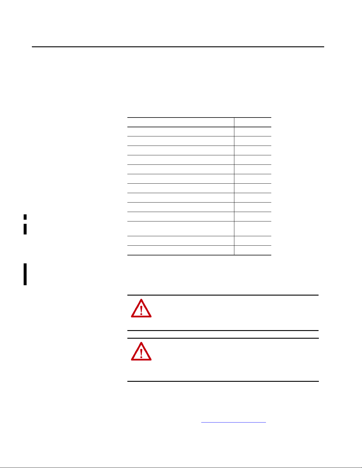
Chapter 4
Options
Reserved
PTC Selected
Thermos tat
Reserved
Reserved
Reserved
Reserved
Reserved
Reserved
Reserved
Reserved
Reserved
Volt age Lo ss
Over Temp
Short Cirkt
Thrmlsn sor OK
Default0000000000000000
Bit 1514131211109876543210
0 = Condition False
1 = Condition True
ATEX Monitoring
Top ic Pag e
Parameter 41 [ATEX Sts] 37
ATEX Fault Descriptions 38
ATEX Configuration Errors 38
Restart the Drive after an Over-temperature Fault 39
This section describes the parameter 41 [ATEX Sts] bit functionality, the ATEX
faults and configuration errors, and how to restart the drive after an
over-temperature fault.
Parameter 41 [ATEX Sts]
No. Display Name
Full Na me
File
11-Series I/O
Group
Motor PTC
Description
41 ATEX Sts
ATEX Status
This parameter is not latched and only displays the status of the ATEX thermal sensor. When an ATEX fault is present, the corresponding bit value is 1.
When motor temperature is within the optimal range, the bit value is 0.
This parameter is available only when an ATEX option module is installed.
Parameter 41 [ATEX Sts] appears in the 11-Series I/O file, Motor PTC group,
when the ATEX option module is installed.
This parameter provides the status of the ATEX thermal sensor. If an ATEX fault
occurs, the corresponding bits change. When the temperature falls below the trip
point, the bits change back to their original settings.
A descriptive fault message is displayed. The fault message can be retrieved from
the fault queue after you clear the fault message from the display.
Value s
Read-write
Data Type
RO 16-bit
Integer
Bit 0 “Thrmlsnsor OK” – Thermal sensor is Ok.
Bit 1 “Short Cirkt” – Short circuit fault that is detected by thermal sensor.
Bit 2 “Over Temp” – Over temperature fault that is detected by thermal sensor.
Bit 3 “Voltage Loss” – Voltage loss fault has taken place on ATEX board.
Bit 13 “Thermostat” – Thermostat input has been selected.
Bit 14 “PTC Selected” – PTC input has been selected.
Rockwell Automation Publication 750-UM003E-EN-P - August 2020 37

Chapter 4
ATEX Fault Descriptions
Ta b l e 3 contains a list of ATEX-specific faults, a description, and the corrective
action (where applicable).
Table 3 - ATEX Faults, Descriptions, and Actions
Event
Faul t/Alar m Text Type Faul t
(1)
No.
xx011 PTC Over Temp Resettable
fault
xx012 PTC ShortCircuit A shor t circuit condition has been detected in the
xx013 ATX VoltageLoss Possible hardware damage.
xx014 ThermostatOvrTmp An over-temperature condition has been
(1) xx indicates the port number where the ATEX option module is installed.
(2) These faults initiate the ATEX function (uncontrolled stop).
Action
Coast An over-temperature condition has been
Description/Corrective Ac tion
(2)
detected in the motor, or the sensor path has
been broken.
sensor path. If the fault is unable to be cleared,
make sure the thermal sensor that is connected
is a PTC-type and not thermostatic.
A short in the motor to the thermal sensor.
An excess of electromagnetic compatibility
(EMC) noise due to improper grounding/
shielding.
detected in the motor, or the sensor path has
been broken.
ATEX Configuration Errors
Ta b l e 4 shows an example of the device conflict text. A conflict can be enunciated
under these conditions:
• During power-up, when the ATEX safety configuration switch is set
improperly.
• If the ATEX option module with the 11-Series I/O option module is
installed in a slot other than 4 or 5.
Table 4 - ATEX Configuration Errors
Device Conflict Text Description/Action
X Port 06 The ATEX option module and 11-Series I/O option module is installed in an
unsupported port.
X Port 06 ‘Safe Speed Montr’ The safety configuration switch (S1-1) is set to ‘ON’, and a safety option is
present.
38 Rockwell Automation Publication 750-UM003E-EN-P - August 2020

Chapter 4
Restart the Drive after an Over-temperature Fault
The drive enters a stop condition and stops current flow to the motor when an
over-temperature condition is sensed in the motor.
To restart the drive, follow these steps.
1. To acknowledge the fault, press the Clear soft key.
The fault information is removed so that you can use the HIM.
2. Fix the condition that caused the fault.
The cause must be corrected before the fault can be cleared.
3. Clear the fault by one of these methods:
• Press Stop (stops the drive)
•Cycle drive power
• Select the Clear soft key on the HIM Diagnostic folder Faults menu
4. Perform any reset sequence that is required by any other installed options,
such as a Safe Speed Monitor option module.
5. Issue a valid start command to the drive.
TIP For more information on faults and how to restart the drive, see the
troubleshooting section in the manual for your drive:
• PowerFlex 750-Series AC Drives Programming Manual,
publication 750-PM001
• PowerFlex Drives with TotalFORCE Control Programming Manual,
publication 750-PM100
Rockwell Automation Publication 750-UM003E-EN-P - August 2020 39

Chapter 4
Notes:
40 Rockwell Automation Publication 750-UM003E-EN-P - August 2020

Appendix A
Specifications and Certifications
Top ic Page
General Specifications 41
11-Series I/O Option Module Terminal Block Specifications 41
Environmental Specifications 42
Certifications 43
This appendix provides specifications for the PowerFlex® ATEX option module
with the 11-Series I/O option module.
General Specifications
11-Series I/O Option Module Terminal Block Specifications
This table provides general specifications.
Attribute Value
Safety integrity level SIL 1 per IEC 61508 (see Safety Data on page 42)
Conductor type Shielded twisted-pair cable, max length 150 m (492 ft)
Conduc tor size
Strip length 6.0 mm (0.24 in.)
Screwdriver blade DIN 5264
PTC over-temperature trip resistance >3.2 kΩ
PTC short circuit trip resistance <100 Ω
PTC receiver ckt IEC 60947-8 or EN 60947-8 compatible
(1) See the Industrial Automation Wiring and Grounding Guidelines, publication 1770-4.1.
(1)
0.3…2.5 mm2 (28…14 AWG)
This table provides wire size, torque, and wire strip length for the 11-Series I/O
option module.
11-Series I/O
Option Module
Terminal Block
TB1 Screw terminals 2.5
TB2 Screw terminals 4.0
Terminal Type Wire S ize Range
Tension clamp terminals 2.5
Tension clamp terminals 4.0 (12) 0.25
2
mm
(AWG)
Max Min Max Reco mmended
(14) 0.3 (28) 0.25 (2.2) 0.2 (1.8) 6 (0.24)
(14) 0.13 (26) N/A 10 (0.39)
(12) 0.25 (24) 0.5 (4.4) 0.4 (3.5) 7 (0.28)
Tor que
N•m (lb•in)
(24) N/A 10 (0.39)
Strip Length
mm (in.)
Rockwell Automation Publication 750-UM003E-EN-P - August 2020 41

Appendix A
Safety Data
The PFD and PFH values in Ta b l e 5 were calculated based on equations in
IEC 61508. This table shows the worst case calculated values for drive frames
1…10 with a proof test interval of 20 years.
IMPORTANT A proof test is not defined in this user manual. A proof test interval of 20
years is used for the calculations here.
These values show the SIL 1 consumption of the ATEX safety function to be
approximately 30%. The safety calculations represent the local ATEX safety path
from the input of the ATEX daughter card to the device that disables
heat-producing power.
Table 5 - PFD and PFH for 20-year Proof Test Interval for All PowerFlex 753/755 and PowerFlex
755T Drives
Attribute Value
Safety integrity level (SIL) 1
Hardware fault tol erance (HFT) 0
Mission Time (MT) 20
Probability of failure on demand (PFD) <3.09E-02
Probability of failure per hour (PFH [1/hour]) <3.53E-07
Environmental Specifications
The installation must comply with all environmental, pollution degree, and drive
enclosure rating specifications required for the operating environment.
Category Specification
Ambient temperature For detailed information on environmental, pollution degree, and drive enclosure
Storage temperature
Shock
Operating
Packaged for shipment
Vibration
Operating
Packaged for shipment
Sinusoidal load
Random secured
Surrounding environment
rating specifications, see the technical data publication for your drive:
• PowerFlex 750-Series AC Drives Technical Data,
publication 750-TD001
• PowerFlex 750-Series Products with TotalFORCE Control Tech nical Data,
publication 750-TD100
• PowerFlex 755TM IP00 Open Type Kits Technical Data,
publication 750-TD101
ATT EN TI ON : Failure to maintain the specified ambient temperature can
result in a failure of the safety function.
42 Rockwell Automation Publication 750-UM003E-EN-P - August 2020
IMPORTANT Products with a safety function installed must be protected against
conductive contamination by one of the following methods:
• Select a product with an enclosure type of at least IP54,
NEMA/UL Type 12
• Provide an environmentally controlled location for the product that does
not contain conductive contamination
Table 6 - Environmental Pollution Degree Description According to EN 61800-5-1
Appendix A
Certifications
Surrounding Environment
Pollution Degree
Pollution degree 1 and 2. No possibility of conductive dust. All enclosures are acceptable.
Pollution degree 3 and 4. A possibility of conductive dust is
Conductive Contamination
Allowed by Pollution Degree
allowed.
Acceptable Enclosures
Enclosure that meets or exceeds
IP54, NEMA/UL Type 12 is required.
The ATEX option module (catalog number 20-750-ATEX) together with the
11-Series I/O option module (catalog numbers 20-750-1132D 2R,
20-750-1133C-1R2T, or 20-750-1132C-2R) are certified to be in conformity
with the legislation and standards that are listed in this table.
Certification
c-UL-us (U.S. and Canada)
CE (Europe) Low Voltage Directive (2014/35/EU)
Regulatory Compliance Mark Radiocommunications Act: 1992
KCC (Korea) Radio Waves Act: Article 58-2
(1)
Legislation/Standard/Certificate
(2)
UL 508C (U.S.); C22.2 No.14 (Canada); and UL 61800-5-1
EN 61800-5-1
EMC Directive (2014/30/EU)
EN 61800-3
ATEX Directive (2014/34/EU)
EC-Type-Examination Certificate Number:
TÜV 17 ATEX 7990 X
EN 50495
Radiocommunications (EMC) Standard: 2012
Radiocommunications Labeling (EMC) Notice: 2008
IEC 61800-3
(1) Certification information can be viewed at , http://rok.auto/certific ations.
(2) Underwriters Laboratories Inc. has not evaluated the ATEX option module for functional safety.
Rockwell Automation Publication 750-UM003E-EN-P - August 2020 43

Appendix A
Notes:
44 Rockwell Automation Publication 750-UM003E-EN-P - August 2020

Index
Numerics
20-750-1132C-2R 10
20-750-1132D-2R
20-750-1133C-1R2T
20-750-ATEX
20-750-S
20-750-S1
20-750-S3
20-750-S4
10
10
10
18
18
18, 21
18, 21
A
ATEX
12
circuitry
configuration errors
X Port 06
38
X Port 06 ‘Safe Speed Montr’
installation example
ATEX directive 2014/34/EU
Category 2
GD
Group II
ATEX option module
configure for PTC mode
configure for thermostat mode
insulation wrapper
used with a safety option module 21
used without a safety option module
7
7
7
11
18
22
22
38
20
E
EnC 27, 28, 30
27, 28, 30
EnNO
explosion risk
explosive atmosphere
7, 9, 10, 27, 28, 29, 31
7, 11
F
failure analysis 13
fault desriptions
ATEX-specific faults
fault reset sequence
fault text
ATX VoltageLoss
PTC Over Temp
PTC ShortCircuit
ThermostatOvrTmp
functional proof test
over temperature
PTC devices
short circuit
test fixture for PTC devices 33
test fixture for thermostat contacts
thermostat contacts
without a test fixture 34
functional testing
functional tests
38
30
38
38
38
38
33
33
34
32
31
16
32
B
backplane 30
bus voltage test points
verify discharge
25, 34
C
cabling requirements
thermal sensor
catalog numbers
11-Series I/O option modules
ATEX option module 10
Integrated Safety Functions option mod ule
Integrated Safety Safe Torque Off
Safe Speed Monitor option module 18
Safe Torque Off option module
spare terminal plug kits
configuration errors
X Port 06
X Port 06 ‘Safe Speed Montr’
24
10
18
18
10
38
38
D
drive enclosure rating specifications 42
drive ports
dry contact
dust
26
28, 29
7
gas vapors 7
hardware fault tolerance 12
installation environment 42
dust environments
installation example
11
18
ATEX
jumper
configure the safety enable
safety enable
safety enable installed
safety enable removed
G
H
I
8
J
23
19
20
22
Rockwell Automation Publication 750-UM003E-EN-P - August 2020 45

Index
M
motor
ATEX certified
ATEX guidelines
certification nameplate
dust environments
flameproof construction
insulation fault
labeled for hazardous areas 8
nameplates
over-temperature signal
protected by enclosure 8
thermal sensor
10
8
8
8
8
11
8
8
11
O
option modules
integrated safety functions (20-750-S4)
integrated safety safe torque off (catalog
safe speed monitor (20-750-S1) 28
safe torque off (20-750-S)
over-temperature
event
functional proof test 33
number 20-750-S3)
27
32
30
29
P
parameter
41 ATEX Sts
44 Safe Stop Input 29
45 Safe Stop Type
933 Start Inhibits
PFD 42
42
PFH
pollution degree
positive temperature coefficient
devices
proof test interval
8, 11
PTC
trip resistance
PTC mode
24, 37
29
32, 33, 34, 35
42
8, 11
33
42
33
22
R
radio frequency (RF) emission compliance 25
reset the drive
resistors
restart the drive
risk
assessment
of explosion 10, 27, 28, 29, 31
30
33
39
15
safe speed monitor parameters
29
P44
P45
29
safety
16
analysis
configuration switch (S1-1)
enable jumper
function test
input signal trigger
reaction time 13
signal on backplane
shock and vibration
short-circuit functional proof test
28, 29, 42
SIL 1
SIL capability
SK-R1-SCRWTB-EIO
SK-R1-SPRGTB-EIO
spare terminal plug kits
specifications
stop condition
configure
31
28, 29
41
39
19, 20, 22
23
42
10
10
18
13
30
10
T
temperature
42
ambient
storage
42
terminals
12, 27, 28
EnC
EnNO 12, 27, 28
test
safety function
thermal sensor
cabling requirements
switch (S1-2) 18
wiring
thermostat contacts
functional proof test
thermostat mode
thermostatic switches
31
11, 16
24
24
32
22
32
U
user manuals
safe speed monitor
safe torque off
23
23
W
wiring
safe speed monitor option module
safe torque-off option module
thermal sensor
24
34
28
27
S
S1 switches
18
S1-1
18
S1-2
safe state
46 Rockwell Automation Publication 750-UM003E-EN-P - August 2020
12

PowerFlex 750-Series ATEX Option Module User Manual
Rockwell Automation Publication 750-UM003E-EN-P - August 2020 47

Rockwell Automation Support
Use these resources to access support information.
Technical Support Center Find help with how-to videos, FAQs, chat, user forums, and product notification updates. rok.auto/support
Knowledgebase Access Knowledgebase articles. rok.auto/knowledgebase
Local Technical Support Phone Numbers Locate the telephone number for your country. rok.auto/phonesupport
Literature Library Find installation instructions, manuals, brochures, and technical data publications. rok.auto/literature
Product Compatibility and Download Center
(PCDC)
Download firmware, associated files (such as AOP, EDS, and DTM), and access product
release notes.
rok.auto/pcdc
Documentation Feedback
Your comments help us serve your documentation needs better. If you have any suggestions on how to improve our
content, complete the form at rok.auto/docfeedback
.
Waste Electrical and Electronic Equipment (WEEE)
At the end of life, this equipment should be collected separately from any unsorted municipal waste.
Rockwell Automation maintains current product environmental compliance information on its website at rok.auto/pec.
Allen-Bradley, expanding human possibility, PowerFlex, TotalFORCE, Rockwell Automation, and Rockwell Software are trademarks of Rockwell Automation, Inc.
EtherNet/IP is a trademark of ODVA, Inc.
Trademarks not belonging to Rockwell Automation are property of their respective companies.
Rockwell Otomasyon Ticaret A.Ş. Kar Plaza İş Merkezi E Blok Kat:6 34752, İçerenköy, İstanbul, Tel: +90 (216) 5698400 EEE Yönetmeliğine Uygundur
Publication 750-UM003E-EN-P - August 2020
Supersedes Publication 750-UM003D-EN-P - March 20 17 Copyright © 2020 Rockwell Automation, Inc. All rights reserved. Printed in the U.S.A.
 Loading...