

Page 1

PowerFlex 750-Series Safe
Torque Off Option Module
Catalog Number 20-750-S
User Manual
Original Instructions
Page 2
PowerFlex 750-Series Safe Torque Off Option Module User Manual
Important User Information
Read this document and the documents listed in the additional resources section about installation, configuration, and
operation of this equipment before you install, configure, operate, or maintain this product. Users are required to familiarize
themselves with installation and wiring instructions in addition to requirements of all applicable codes, laws, and standards.
Activities including installation, adjustments, putting into service, use, assembly, disassembly, and maintenance are required to
be carried out by suitably trained personnel in accordance with applicable code of practice.
If this equipment is used in a manner not specified by the manufacturer, the protection provided by the equipment may be
impaired.
In no event will Rockwell Automation, Inc. be responsible or liable for indirect or consequential damages resulting from the use
or application of this equipment.
The examples and diagrams in this manual are included solely for illustrative purposes. Because of the many variables and
requirements associated with any particular installation, Rockwell Automation, Inc. cannot assume responsibility or liability for
actual use based on the examples and diagrams.
No patent liability is assumed by Rockwell Automation, Inc. with respect to use of information, circuits, equipment, or software
described in this manual.
Reproduction of the contents of this manual, in whole or in part, without written permission of Rockwell Automation, Inc., is
prohibited.
Throughout this manual, when necessary, we use notes to make you aware of safety considerations.
WA RN I NG : Identifies information about practices or circumstances that can cause an explosion in a hazardous environment,
which may lead to personal injury or death, property damage, or economic loss.
ATTENTION: Identifies information about practices or circumstances that can lead to personal injury or death, property
damage, or economic loss. Attentions help you identify a hazard, avoid a hazard, and recognize the consequence.
IMPORTANT Identifies information that is critical for successful application and understanding of the product.
Labels may also be on or inside the equipment to provide specific precautions.
SHOCK HAZARD: Labels may be on or inside the equipment, for example, a drive or motor, to alert people that dangerous
voltage may be present.
BURN HAZARD: Labels may be on or inside the equipment, for example, a drive or motor, to alert people that surfaces may
reach dangerous temperatures.
ARC FLASH HAZARD: Labels may be on or inside the equipment, for example, a motor control center, to alert people to potential
Arc Flash. Arc Flash will cause severe injury or death. Wear proper Personal Protective Equipment (PPE). Follow ALL Regulatory
requirements for safe work practices and for Personal Protective Equipment (PPE).
2 Rockwell Automation Publication 750-UM002J-EN-P - February 2021
Page 3

Table of Contents
Preface
Summary of Changes . . . . . . . . . . . . . . . . . . . . . . . . . . . . . . . . . . . . . . . . . . . 5
Conventions. . . . . . . . . . . . . . . . . . . . . . . . . . . . . . . . . . . . . . . . . . . . . . . . . . . 5
Terminology. . . . . . . . . . . . . . . . . . . . . . . . . . . . . . . . . . . . . . . . . . . . . . . . . . . 6
Additional Resources . . . . . . . . . . . . . . . . . . . . . . . . . . . . . . . . . . . . . . . . . . . 7
Chapter 1
Safety Concept Certification . . . . . . . . . . . . . . . . . . . . . . . . . . . . . . . . . . . . . . . . . . . . . . . . . . . 9
Important Safety Considerations . . . . . . . . . . . . . . . . . . . . . . . . . . . 10
Safety Category 3 Performance Definition . . . . . . . . . . . . . . . . . . . 10
Stop Category Definitions. . . . . . . . . . . . . . . . . . . . . . . . . . . . . . . . . . 11
Performance Level and Safety Integrity Level (SIL) 3 . . . . . . . . . 11
Proof Tests. . . . . . . . . . . . . . . . . . . . . . . . . . . . . . . . . . . . . . . . . . . . . . . . . . . 11
PFD and PFH Definitions . . . . . . . . . . . . . . . . . . . . . . . . . . . . . . . . . . . . . 12
Safety Data . . . . . . . . . . . . . . . . . . . . . . . . . . . . . . . . . . . . . . . . . . . . . . . . . . . 12
Safe State . . . . . . . . . . . . . . . . . . . . . . . . . . . . . . . . . . . . . . . . . . . . . . . . . . . . . 13
Safety Reaction Time . . . . . . . . . . . . . . . . . . . . . . . . . . . . . . . . . . . . . . . . . . 13
Considerations for Safety Ratings. . . . . . . . . . . . . . . . . . . . . . . . . . . . . . . 14
Contact Information if Safety Option Failure Occurs . . . . . . . . . . . . 14
Chapter 2
Installation and Wiring Remove Power to the System. . . . . . . . . . . . . . . . . . . . . . . . . . . . . . . . . . . 16
Access the Control Pod . . . . . . . . . . . . . . . . . . . . . . . . . . . . . . . . . . . . . . . . 16
Set the Safety Enable Jumper . . . . . . . . . . . . . . . . . . . . . . . . . . . . . . . . . . . 18
Install the Safety Option Module . . . . . . . . . . . . . . . . . . . . . . . . . . . . . . . 19
Wire the Safety Option Module . . . . . . . . . . . . . . . . . . . . . . . . . . . . . . . . 20
Cabling . . . . . . . . . . . . . . . . . . . . . . . . . . . . . . . . . . . . . . . . . . . . . 21
Power Supply Requirements. . . . . . . . . . . . . . . . . . . . . . . . . . . 21
Verify Operation . . . . . . . . . . . . . . . . . . . . . . . . . . . . . . . . . . . . . . . . . . . . . . 22
Chapter 3
Safe Torque Off Option Module
Operation
Operation . . . . . . . . . . . . . . . . . . . . . . . . . . . . . . . . . . . . . . . . . . . . . . . . . . . . 23
Stop Category Wiring Examples. . . . . . . . . . . . . . . . . . . . . . . . . . . . . . . . 24
Appendix A
Specifications, Certifications, and
CE Conformity
Specifications . . . . . . . . . . . . . . . . . . . . . . . . . . . . . . . . . . . . . . . . . . . . . . . . . 31
Environmental Specifications. . . . . . . . . . . . . . . . . . . . . . . . . . . . . . . 32
Certifications . . . . . . . . . . . . . . . . . . . . . . . . . . . . . . . . . . . . . . . . . . . . . . . . . 33
CE Conformity . . . . . . . . . . . . . . . . . . . . . . . . . . . . . . . . . . . . . . . . . . . . . . . 34
Machinery Directive (2006/42/EC) . . . . . . . . . . . . . . . . . . . . . . . . 34
EMC Directive (2014/30/EU) . . . . . . . . . . . . . . . . . . . . . . . . . . . . . 34
Index
. . . . . . . . . . . . . . . . . . . . . . . . . . . . . . . . . . . . . . . . . . . . . . . . . . . . . . . . . 35
Rockwell Automation Publication 750-UM002J-EN-P - February 2021 3
Page 4

Table of Contents
Notes:
4 Rockwell Automation Publication 750-UM002J-EN-P - February 2021
Page 5

Preface
This manual explains how the PowerFlex® 750-Series Safe Torque Off option
module can be used in Safety Integrity Level (SIL) 3, Performance Level [PLe],
or Category (cat.) 3 applications. It describes the safety requirements, including
PFD and PFH values and application verification information, and provides
information on installing, configuring, and troubleshooting the Safe Torque
Off option module.
Use this manual if you are responsible for designing, installing, configuring, or
troubleshooting safety applications that use the PowerFlex 750-Series Safe
To r q u e O ff op ti on mo du l e.
The 20-750-S Safe Torque Off option module applies to the following
PowerFlex 750-Series drives:
• PowerFlex 755TL low harmonic, non-regenerative drives
• PowerFlex 755TR regenerative drives
• PowerFlex 755TM drive systems with regenerative bus-supplies and
common-bus inverters
• PowerFlex 755 AC drives
• PowerFlex 753 AC drives
Summary of Changes
Conventions
Throughout this manual, PowerFlex 755T drive products is used to refer to
PowerFlex 755TL drives, PowerFlex 755TR drives, and PowerFlex 755TM
drive systems.
We recommend that you have a basic understanding of the electrical circuitry
and familiarity with these products. You must also be trained and experienced
in the creation, operation, and maintenance of safety systems.
This manual contains new and updated information as indicated in the
following table.
Top ic Pa ge
Updated Important statement in the Set the Safety Enable Jumper section to describe behavior if
jumper is not set correctly and list drives which do not have the jumper.
Added Environmental Pollution Degree Description (EN 61800-5-1) table to Appendix A. 32
In this manual, we list configuration parameters by number followed by the
name in brackets. For example, P24 [OverSpd Response].
18
Rockwell Automation Publication 750-UM002J-EN-P - February 2021 5
Page 6

Preface
Terminology
Abbreviation Full Term Definition
1oo2 One out of Two Refers to the behavioral design of a dual-channel safety system.
cat. Category Classification of the safety-related parts of a control system in respect of their resistance to faults and
CL Claim Limit The maximum SIL rating that can be claimed for a Safety-Related Electrical Control System subsystem
DCavg% Diagnostic Coverage Ratio between the failure rate of detected dangerous failures and the failure rate of total dangerous
EN European Norm The offi cial European Standard.
ESD Emergency Shutdown Systems A system, usually independent of the main control system, that is designed to shut down an operating
HFT Hardware Fault Tolerance The HFT equals n, where n+1 faults could cause the loss of the safety function. An HFT of 1 means that
HIM Human Interface Module A module used to configure a device.
IEC International Electrotechnical Commission The International Electrotechnical Commission (IEC) is the world’s leading organization that prepares
IGBT Insulated Gate Bi-polar Transistors Typical power switch used to control main current.
ISO International Organization for Standardization The International Organization for Standardization is an international standard-setting body that is
MTTF
D
PELV Protective Extra Low Voltage An electrical system where the voltage cannot exceed ELV under normal conditions, and under single-
PFD Probability of Dangerous Failure on Demand The average probability of a system to fail to perform its design function on demand.
PFH Average Frequency of a Dangerous Failure per Hour The average frequency of a system to have a dangerous failure occur per hour.
PL Performance Level EN ISO 13849-1 safety rating
SELV Safety Extra Low Voltage Circuit A secondary circuit that is designed and protected so that, under normal and single fault conditions, its
SIL Safety Integrity Level A measure of a products ability to lower the risk that a dangerous failure could occur.
STO Safe Torque Off The Safe Torque Off (STO) function is used to prevent unexpected motor rotation if there is an
Mean Time to Failure The average length of time before a device has a dangerous failure.
This table defines abbreviations that are used in this manual.
their subsequent behavior in the fault condition, and which is achieved by the structural arrangement
of the parts, fault detection, and/or by their reliability (source EN ISO 13849-1).
in relation to architectural constraints and systematic safety integrity (source IEC 62061).
failures. (source IEC 61508).
system safely.
2 faults are required before safety is lost.
and publishes International Standards for all electrical, electronic, and related technologies.
composed of representatives from various national standards organizations.
fault conditions, except earth faults in other circuits. PELV is defined in IEC 61131-2.
voltages do not exceed a safe value. SELV is defined in IEC 61010-2-201.
emergency while the drive remains connected to the power supply. When STO is activated, the torque
power cannot reach the drive, thus stopping and preventing any motor shaft rotation.
6 Rockwell Automation Publication 750-UM002J-EN-P - February 2021
Page 7
Preface
Additional Resources
These documents contain additional information concerning related
Rockwell Automation products.
Resource Description
PowerFlex Safe Speed Monitor Safety Reference Manual, publication
System Design for Control of Electrical Noise Reference Manual,
publication GMC-RM001
Safety Guidelines for the Application, Installation, and Maintenance of Solid
State Control, publication
Enhanced PowerFlex 7-Class Human Interface Module (HIM) User Manual,
publication
Connected Components Workbench Online Help
PowerFlex 750-Series Products with TotalFORCE® Control Technical Data,
publication 750-TD100
PowerFlex 750-Series Products with TotalFORCE Control Installation
Instructions, publication
PowerFlex 755TM IP00 Open Type Kits Installation Instructions,
publication
PowerFlex Drives with TotalFORCE Control Programming Manual,
publication
PowerFlex 755TM IP00 Open Type Kits Technical Data, publication 750-TD101
PowerFlex 750-Series AC Drives Technical Data, publication 750-TD001
PowerFlex 750-Series AC Drive Installation Instructions, publication
PowerFlex 750-Series AC Drives Programming Manual, publication
Product Certifications website, rok.auto/certifications Provides declarations of conformity, certificates, and other certification details
20HIM-UM001
750-IN101
750-PM100
SGI-1.1
750-IN100
750-RM001
750-IN001
750-PM001
Provides information on installing and configuring the safe speed monitor option module with
PowerFlex 750-Series drives.
Information, examples, and techniques that are designed to minimize system failures caused by
electrical noise.
Describes important differences between solid-state control and hard wired electro mechanical
devices.
Provides information for using the 20-HIM-A6 Human Interface Module to configure
PowerFlex 750-Series drives and the Safe Torque Off option module.
Online Help that provides a description of the different elements of the Connected Components
Workbench™ software.
Provides detailed information on:
• Drive and bus supply specifications
• Option specifications
• Fuse and circuit breaker ratings
Provides the basic steps to install PowerFlex 755TL drives, PowerFlex 755TR drives, and
PowerFlex 755TM bus supplies.
Provides instructions to install IP00 Open Type kits in user-supplied enclosures.
Provides detailed information on:
• I/O, control, and feedback options
• Parameters and programming
• Faults, alarms, and troubleshooting
Provides detailed information on:
• Kit selection
• Kit ratings and specifications
• Option specifications
Provides detailed information on:
• Packaged drive specifications
• Option specifications
• Fuse and circuit breaker ratings
Provides information on installing the Safe Torque Off option module in PowerFlex 750-Series
drive.
Provides information on mounting, installing, and configuring PowerFlex 750-Series drives.
You can view or download publications at rok.auto/literature
Rockwell Automation Publication 750-UM002J-EN-P- February 2021 7
.
Page 8

Preface
Notes:
8 Rockwell Automation Publication 750-UM002J-EN-P - February 2021
Page 9

Chapter 1
Safety Concept
This chapter describes the safety Performance Level concept and how the
PowerFlex® 750-Series Safe Torque Off option module meets the requirements
for SIL 3, or cat. 3, PLe applications.
Top ic Pa ge
Certification 9
Proof Tests 11
PFD and PFH Definitions 12
Safety Data 12
Safe State 13
Safety Reaction Time 13
Considerations for Safety Ratings 14
Contact Information if Safety Option Failure Occurs 14
Certification
The PowerFlex 750-Series Safe Torque Off option module is certified for use in
safety applications up to and including SIL 3 according to EN/IEC 61800-5-2,
IEC 61508, and SIL CL3 according to EN 62061, Performance Level PLe, and
Category 3 according to EN ISO 13849-1. Safety requirements are based on
the standards current at the time of certification.
The TÜV Rheinland group has approved the PowerFlex 750-Series Safe
Torque Off option module for use in safety-related applications where the deenergized state is considered to be the safe state. The examples in this manual
are based on achieving de-energization as the safe state for typical Machine
Safety and Emergency Shutdown (ESD) systems.
Rockwell Automation Publication 750-UM002J-EN-P - February 2021 9
Page 10
Chapter 1
Important Safety Considerations
The system user is responsible for the following :
• Set-up, safety rating, and validation of any sensors or actuators
connected to the system
• Complete system-level risk assessment and reassess the system any time a
change is made
• Certification of the system to the desired safety Performance Level
• Project management and proof testing
• Program the application software and the safety option module
configurations in accordance with the information in this manual
• Access control to the system
• Analyze all configuration settings and choose the proper setting to
achieve the required safety rating
IMPORTANT When applying Safety, restrict access to qualified, authorized personnel
who are trained and experienced.
ATT EN TI ON : When designing your system, consider how personnel exit the
machine if the door locks while they are in the machine. Additional
safeguarding devices may be required for your specific application.
Safety Category 3 Performance Definition
To achieve Safety Category 3, according to EN ISO 13849-1, design the safetyrelated parts according to these guidelines:
• The safety-related parts of machine control systems and/or their
protective equipment, and their components, shall be designed,
constructed, selected, assembled, and combined in accordance with
relevant standards so that they can withstand expected conditions
• Basic safety principles shall be applied
• A single fault in any of its parts does not lead to a loss of safety function.
• The average diagnostic coverage of the safety-related parts of the control
system shall be medium
• The mean-time to dangerous failure of each of the redundant channels
shall be high
• Measures against common cause failure shall be applied
10 Rockwell Automation Publication 750-UM002J-EN-P - February 2021
Page 11

Chapter 1
Stop Category Definitions
Conduct a risk assessment to determine the selection of a stop category for
each stop function.
• Stop Category 0 is achieved with immediate removal of power to the
actuator. This results in an uncontrolled coast-to-stop. Safe Torque Off
accomplishes a Stop Category 0 stop.
• Stop Category 1 is achieved with power available to the machine
actuators to achieve the stop. Power is removed from the actuators when
the stop is achieved.
IMPORTANT When designing the machine application, consider timing and distance for a
coast-to-stop (Stop Category 0 or Safe Torque Off). For more information
regarding stop categories and Safe Torque Off, refer to EN 60204-1 and
EN/IEC 61800-5-2, respectively.
Performance Level and Safety Integrity Level (SIL) 3
Proof Tests
For safety-related control systems, Performance Level (PL), according to
EN ISO 13849-1, and SIL levels, according to IEC 61508 and EN 62061,
include a rating of the ability of the system to perform its safety functions. All
safety-related components of the control system must be included in both a
risk assessment and the determination of the achieved levels.
See the EN ISO 13849-1, IEC 61508, and EN 62061 standards for complete
information on requirements for PL and SIL determination.
The safety standards require that proof tests be performed on the equipment
that is used in the system. Proof tests are performed at user-defined intervals
and are dependent upon PFD and PFH values.
IMPORTANT Your specific application determines the time frame for the proof test
interval.
Verify operation of safety function after drive installation, modification, or
maintenance. See Verify Operation
on page 22 for more information.
Rockwell Automation Publication 750-UM002J-EN-P - February 2021 11
Page 12
Chapter 1
PFD and PFH Definitions
Safety Data
Safety-related systems can be classified as operating in either a Low Demand
mode, or in a High Demand/Continuous mode.
• Low Demand mode: where the frequency of demands for operation that
are made on a safety-related system is no greater than one per year or no
greater than twice the proof test frequency.
• High Demand/Continuous mode: where the frequency of demands for
operation that are made on a safety-related system is greater than once
per year or greater than twice the proof test interval.
The SIL value for a low-demand safety-related system is directly related to
order-of-magnitude ranges of its average probability of failure to perform its
safety function satisfactorily on demand or, simply, average probability of a
dangerous failure on demand (PFD). The SIL value for a High Demand/
continuous mode safety-related system is directly related to the average
frequency of a dangerous failure occurring per hour (PFH).
PFD and PFH calculations are based on the equations from Part 6 of
IEC 61508.
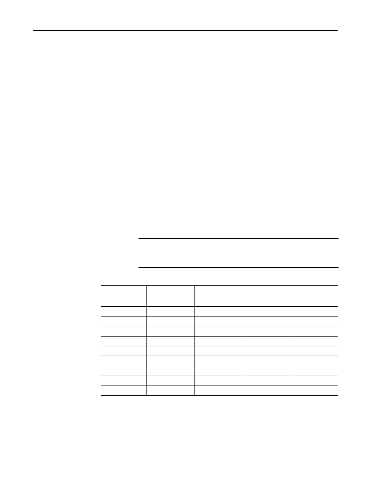
These tables provide data for a 20-year proof test interval and demonstrate the
worst-case effect of various configuration changes on the data.
IMPORTANT Determination of safety parameters is based on the assumptions that the
system operates in High-demand mode and that the safety function is
requested at least once every year.
Table 1 - PFD and PFH for PowerFlex 753 and PowerFlex 755 Drives
Attribute
PFD
avg
PFH (1/hour) 3.75E-10 1.99E-9 3.04E-9 4.09E-9
SIL3333
PLeeee
Category3333
MTTF
years 143 171.9 104.4 75.5
D
% 99 (high) 97.4 (high) 97.5 (high) 97.5 (high)
DC
avg
HFT 1 (1oo2) 1 (1oo2) 1 (1oo2) 1 (1oo2)
Mission time 20 years 20 years 20 years 20 years
PowerFlex 753 and
PowerFlex 755 Drives
Frames 1…7
3.29E-5 1.73E-4 2.65E-4 3.56E-4
PowerFlex 755 Drives
Frame 8
PowerFlex 755 Drives
Frame 9
PowerFlex 755 Drives
Frame 10
12 Rockwell Automation Publication 750-UM002J-EN-P - February 2021
Page 13

Table 2 - PFD and PFH for PowerFlex 755T Drive Products
Chapter 1
Attribute
PFD
avg
PFH (1/hour) 4.22E-10 2.86E-9 3.15E-9 3.45E-9 3.75E-9 4.05E-9 4.34 E-9 4.94 E-9 5.54 E-9
SIL333333333
PLeeeeeeeee
Category333333333
MTTF
years 1055.5 (high) 186.7 (high) 142.7 (high) 115.5 (high) 97.0 (high) 83.7(high) 73.5 (high) 59.2 (high) 49.5 (high)
D
DC
% 94.8 (high) 96.3 (high) 96.4 (high) 96.6 (high) 96.6 (high) 96.6 (high) 96.7 (high) 96.7 (high) 96.7 (high)
avg
HFT 1 (1oo2) 1 (1oo2) 1 (1oo2) 1 (1oo2) 1 (1oo2) 1 (1oo2) 1 (1oo2) 1 (1oo2) 1 (1oo2)
Mission time 20 years 20 years 20 years 20 years 20 years 20 years 20 years 20 years 20 years
Drive Frame
5 and 6
3.70E-5 2.48E-4 2.74E-4 3.00E-4 3.26E-4 3.52E-4 3.77 E-4 4.29 E-4 4.81 E-4
Safe State
Drive Frame
7 and 8
Drive Frame 9Drive Frame 10Drive Frame 11Drive Frame 12Drive Frame 13Drive Frame 14Drive Frame
15
The safe state encompasses all operation that occurs outside of the other
monitoring and stopping behavior that is defined as part of the Safe Torque
Off option module.
If a Safe State fault is detected, the safety option module transitions to the safe
state. This includes faults that are related to the integrity of hardware or
firmware. The drive safe state is defined as preventing force-producing power
from being provided to the motor. For more information on the safe state, see
EN/IEC 61800-5-2.
Safety Reaction Time
IMPORTANT The drive is in the safe state if the safety function is installed and the drive
status is ‘Not Enabled’. Drive ‘Ready’ is NOT a safe state even if there is no
motion.
ATT EN TI ON : In circumstances where external influences (for example,
falling of suspended loads) are present, additional measures (for example,
mechanical brakes) can be necessary to help prevent a hazard.
The safety reaction time is the length of time from a safety-related event as
input to the system until the system is in the safe state.
The safety reaction time from an input signal condition that triggers a safe
stop, to the initiation of the configured Stop Type, is shown in Ta b l e 3
.
Rockwell Automation Publication 750-UM002J-EN-P - February 2021 13
Page 14

Chapter 1
SE
SP
Safe Torque O
Safety Reaction Time
Table 3 - Safety Reaction Time
Drive Family Value, M ax
PowerFlex 753 drives
Frames 1…7
PowerFlex 755 drives
Frames 1…10
PowerFlex 755TL drives,
PowerFlex 755TR drives, and
PowerFlex 755TM drive systems
Frames 7…15
PowerFlex 755TL drives
Frames 5, 6
10 ms
10 ms
10 ms
20 ms
IMPORTANT An input signal condition that is present for less than the reaction time
cannot result in the safety function being performed. Repeated requests of
the safety function for less than the reaction time can result in a spurious
detection of a fault.
Figure 1 - Safety Reaction Timing Diagram
Considerations for Safety Ratings
The achievable safety rating of an application using the safety option module
installed in PowerFlex 750-Series drives is dependent upon many factors, drive
options, and the type of motor.
For applications that rely on the immediate removal of power to the actuator,
which results in an uncontrolled coast-to-stop, a safety rating up to and
including SIL 3, PLe, and Category 3 can be achieved.
Contact Information if Safety Option Failure Occurs
If you experience a failure with any safety-certified device, contact your local
Allen-Bradley distributor. With this contact, you can do the following:
• Return the device to Rockwell Automation so the failure is
appropriately logged for the catalog number that is affected and a record
is made of the failure.
• Request a failure analysis (if necessary) to determine the probable cause
of the failure.
14 Rockwell Automation Publication 750-UM002J-EN-P - February 2021
Page 15

Chapter 2
Installation and Wiring
This chapter provides installation, jumper settings, and wiring for the
PowerFlex® 750-Series Safe Torque Off option module.
Top ic Pa ge
Remove Power to the System 16
Access t he Control Pod 16
Set the Safety Enable Jumper 18
Install the Safety Option Module 19
Wire the Safety Option Module 20
Verify Operat ion 22
ATT EN TI ON : The following information is merely a guide for proper
installation. Rockwell Automation cannot assume responsibility for the
compliance or the noncompliance to any code, national, local or otherwise
for the proper installation of this equipment. A hazard of personal injury
and/or equipment damage exists if codes are ignored during installation.
IMPORTANT Installation must be in accordance with the instructions in this user manual
and the installation instructions for your drive. Only qualified, authorized
personnel that are trained and experienced in safety can plan, implement,
and apply safety systems.
IMPORTANT During installation and maintenance, check your drive firmware release
notes for known anomalies and verify that there are no safety-related
anomalies.
The PowerFlex 750-Series Safe Torque Off option module is intended to be
part of the safety-related control system. Before installation, perform a risk
assessment that compares the PowerFlex 750-Series Safe Torque Off option
module specifications and all foreseeable operational and environmental
characteristics of the control system.
A safety analysis of the machine section that is controlled by the drive is
required to determine how often to test the safety function for proper
operation during the life of the machine.
Rockwell Automation Publication 750-UM002J-EN-P - February 2021 15
Page 16

Chapter 2
Remove Power to the System
Before performing any work on this drive, remove all power to the system.
ATT EN TI ON :
• Electrical Shock Hazard. Verify that all sources of AC and DC power are deenergized and locked out or tagged out in accordance with the requirements
of ANSI/NFPA 70E, Part II.
• To avoid an electric shock hazard, verify that the voltage on the bus
capacitors has discharged before performing any work on the drive. Measure
the DC bus voltage at the +DC and -DC terminals or test points. The voltage
must be zero.
For the location of the terminal block and test point sockets, see the manual for
your drive:
• PowerFlex 750-Series AC Drives Installation Instructions, publication
750-IN001
• PowerFlex 750-Series Products with TotalFORCE Control Installation
Instructions, publication 750-IN100
• PowerFlex 755TM IP00 Open Type Kits Installation Instructions, publication
750-IN101
• In Safe Torque Off mode, hazardous voltages may still be present at the
motor. To avoid an electric shock hazard, disconnect power to the motor and
verify that the voltage is zero before performing any work on the motor.
.
.
.
Access the Control Pod
The option module is installed in the drive control pod. Different drives have
different ways to access the control pod.
To access the control pod, follow these steps.
1. Open the door or remove cover.
2. Loosen the retention screw on the HIM cradle.
16 Rockwell Automation Publication 750-UM002J-EN-P - February 2021
Page 17

3. Lift the cradle until the latch engages.
Panel-mo unted D rives
Drives in Cabinet Enclosures
Chapter 2
See the installation instructions for your drive for more information.
Rockwell Automation Publication 750-UM002J-EN-P - February 2021 17
Page 18

Chapter 2
PowerFlex 753 AC Drive
SAFETY Enable
(jumper removed)
Hardware ENABLE (jumper in place)
PowerFlex 755 AC Drive
SAFETY Enable
(jumper removed)
Hardware ENABLE (jumper in place)
Set the Safety Enable Jumper
The PowerFlex 750-Series drives ship with the safety-enable (SAFETY)
jumper installed. The jumper, which is on the main control board, must be
removed when using the Safe Torque Off option module or a Safety Jumper In
fault (F213) occurs.
IMPORTANT A fault occurs on power up if the SAFETY Enable jumper is not set correctly.
PowerFlex 755 drives (frames 8…10) control boards do not have a SAFETY
jumper.
Figure 2 - PowerFlex 753 Drive Jumper Locations
Figure 3 - PowerFlex 755 Drive Jumper Locations (Frames 1…7 only)
PowerFlex 755 drives (frames 8, 9, and 10) do not have a safety enable jumper.
18 Rockwell Automation Publication 750-UM002J-EN-P - February 2021
Page 19

Figure 4 - PowerFlex 755T Drive Products Jumper Locations
PowerFlex 755TL,
PowerFlex 755TR, and
PowerFlex 755TM Control Pod
SAFETY Enable
(jumper removed)
Hardware ENABLE
(jumper in place)
Chapter 2
Install the Safety Option Module
To install the Safe Torque Off option module:
1. Firmly press the module edge connector into the desired port.
IMPORTANT The Safe Torque Off option module can be installed in any drive port.
However, when used in an integrated motion application, the
module must be installed in port 6.
IMPORTANT Only one safety option module can be installed at a time. Installing
multiple or duplicate safety option modules is not supported.
2. Tighten the top and bottom retaining screws.
– Recommended torque = 0.45 N•m (4.0 lb•in)
– Recommended screwdriver = T15 Hexalobular
IMPORTANT Do not overtighten retaining screws.
Rockwell Automation Publication 750-UM002J-EN-P - February 2021 19
Page 20

Chapter 2
PowerFlex 755 Frame 2 is shown
TB2
20-750-S Safe Torque Off
Option Module
-
-
Wire the Safety Option Module
Observe these wiring guidelines when installing the safety option module:
• Use copper wire with an insulation rating of 600V or greater is
recommended.
• Separate control wires from power wires by at least 0.3 m (1 ft).
Table 4 - Safety Option Module Terminal Block Specifications
Wire Size Range
Maximum Minimum
2
0.8 mm
(18 AWG)
0.3 mm2
(28 AWG)
Table 5 - TB2 Terminal Designations
Terminal Name Description
SP+ +24 Volt Safety Power
SP
SP+
SE
SE+
Sd
Safety Input Connection Example
Dedicated Power Supply
SP- Safety Power Common
Sd
SE+ +24 Volt Safety Enable
SE- Safety Enable Common
Sd Shield
Sd Shield
Common
+24V
Wire Type Strip Length
Multi-conductor shielded
cable
10 mm
(0.39 in.)
User-supplied power: 24 volt ±10%
45 mA typical
User-supplied power: 24 volt ±10%
25 mA typical
Terminating point for wiring shields when an
EMC plate or conduit box is not installed.
SPSP+
Sd Sd
SE-
SE+
Common
+24V
20 Rockwell Automation Publication 750-UM002J-EN-P - February 2021
Page 21

Chapter 2
Cabling
Safety input wiring must be protected against external damage by cable
ducting, conduit, armored cable, or other means.
Shielded cable is required. For proper shield termination, follow the
installation requirements that are related to EN 61800-3 and the EMC
Directive as described in these publications:
• PowerFlex 750-Series AC Drive Installation Instructions, publication
750-IN001
• PowerFlex 750-Series Products with TotalFORCE Control Installation
Instructions, publication
750-IN100
Power Supply Requirements
The external power supply must conform to the Directive 2014/35/EU
Low Voltage, by applying the requirements of EN61131-2 Programmable
Controllers, Part 2 - Equipment Requirements and Tests and one of the
following:
• EN60950 - SELV (Safety Extra Low Voltage)
• EN60204 - PELV (Protective Extra Low Voltage)
• IEC 60536 Safety Class III (SELV or PELV)
• UL 508 Limited Voltage Circuit
• 24V DC ±10% must be supplied by a power supply that complies with
IEC 60204 and IEC 61558-1.
For specific power supply recommendations, refer to your drive installation
instructions:
• PowerFlex 750-Series Products with TotalFORCE Control Installation
Instructions, publication
• PowerFlex 750-Series AC Drives Installation Instructions, publication
750-IN001
For planning information, see the guidelines in Industrial Automation Wiring
and Grounding Guidelines, publication 1770-4.1
.
750-IN100
.
.
Rockwell Automation Publication 750-UM002J-EN-P - February 2021 21
Page 22

Chapter 2
Verify Operation
Test the safety function for proper operation after initial installation of the
safety option module. Retest the safety function at the intervals that are
determined by the safety analysis that is described on page 15
Verify that both safety channels are functioning according to Ta b l e 6
Table 6 - Channel Operation and Verification
Safety Function Status
Safety Channel Operation
Safety Option Module
Ter min al s SP+ & SP-
(safety power)
Safety Option Module
Ter min al s SE+ & SE-
(safety enable)
Drive Not
Enabled
No Power Applied Power Applied No Power Applied Power Applied
No Power Applied No Power Applied Power Applied Power Applied
Drive Not
Enabled
Drive Not
Enabled
.
.
Drive Enabled
(Ready)
IMPORTANT If an external fault is present on the wiring or circuitry controlling the Safety
Enable or Safety Power inputs for a period of time, the safety option module
does not detect this condition. When the external fault condition is
removed, the safety option module allows an enable condition.
To achieve maximum safety rating, both safety inputs SP and SE must be
activated by appropriate dual-channel equipment. The repeated activation
of the safety function by only one input at a time can result in a spurious
detection of a fault.
TIP There is no safe-status output provided on the safety option module.
22 Rockwell Automation Publication 750-UM002J-EN-P - February 2021
Page 23

Chapter 3
Safe Torque Off Option Module Operation
This chapter provides operation and Stop Category example wiring diagrams
for the PowerFlex® 750-Series Safe Torque Off option module.
Top ic Pa ge
Operation 23
Stop Category Wiring Examples 24
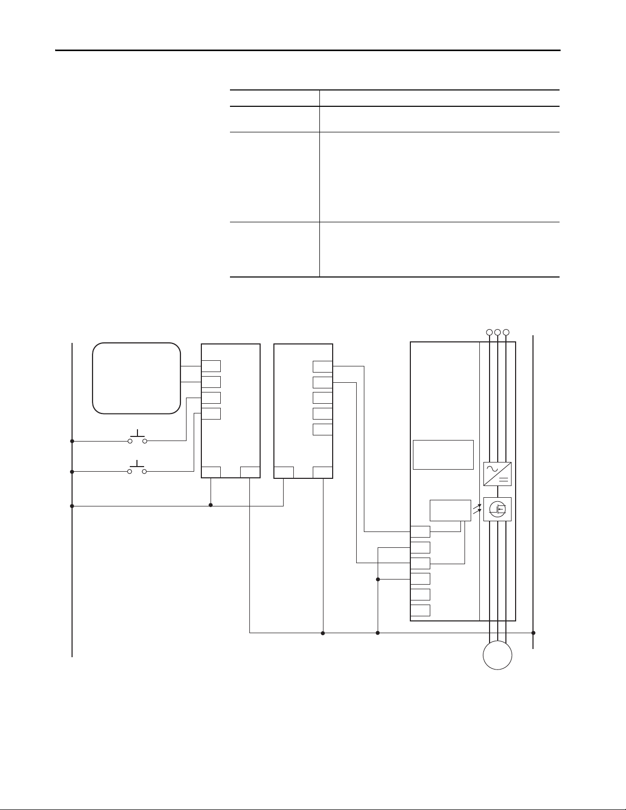
Operation
The PowerFlex 750-Series Safe Torque Off option module (see Figure 5)
disables the drive’s output IGBTs by disconnecting power to the gate control
driver IC, or disabling the output of the gate-control driver IC. This helps
prevent the drive’s output power devices from switching in the pattern
necessary to generate AC power to the motor.
The safety option module can be used in combination with other safety devices
to satisfy the requirements of IEC 61508, EN/IEC 61800-5-2 SIL 3,
EN ISO 13849-1 PLe, and Category 3 for Safe Torque Off (STO).
IMPORTANT The safety option module is suitable for performing mechanical work on the
drive system or affected area of a machine only. It does not provide electrical
safety.
Do not use the safety option module as a control for starting and/or
stopping the drive.
IMPORTANT The safety option module does not eliminate dangerous voltages at the
drive output. Input power to the drive must be turned off and safety
procedures followed before performing any electrical work on the drive or
motor. See Remove Power to the System
on page 16 for more information.
ATT EN TI ON : In the event of the failure of two output IGBTs in the drive,
when the safety option module has controlled the drive outputs to the OFF
state, the drive can provide energy for up to 180° of rotation in a 2-pole
motor before torque production in the motor ceases.
Under normal operation, 24V DC is applied to both the Safety Power and
Safety Enable inputs of the safety option module. If the Safety Enable or Safety
Rockwell Automation Publication 750-UM002J-EN-P - February 2021 23
Page 24

Chapter 3
AC Line Input
Power
PowerFlex 750-Series
AC Drives
+24V DC
Stop
Start
Start/Stop Common
24V DC Common
Jumpers:
ENABLE Installed
SAFETY Removed
Gate Control
Safety
Power
Safety
Enable
Motor
Power is de-energized, the outputs of the gate-control driver IC are disabled
and IGBT firing is disabled. On the PowerFlex 753/755, parameter 933 [Start
Inhibits] indicates that IGBTs are inhibited and the HIM indicates that the
drive is not enabled. On the PowerFlex 755T, this is indicated in parameter
10:351 [M Start Inhibits].
ATT EN TI ON : By itself, the safety option module initiates a coast-to-stop
action. Additional protective measures must be applied when an application
requires a different stopping action.
Figure 5 - Drive Safe Torque Off Circuitry
Stop Category Wiring Examples
SP+
SP–
SE+
SE–
Sd
Sd
The following diagrams illustrate Stop Category 0 and Stop Category 1 dualchannel wiring examples for PowerFlex 750-Series drives with Guardmaster®
safety relays. Examples include the following drive families:
• PowerFlex 753 and PowerFlex 755 Drives, Frames 1…10
• PowerFlex 755T Drive Products, Frames 5…15
24 Rockwell Automation Publication 750-UM002J-EN-P - February 2021
Page 25

Figure 6 - Stop Category 0
AC Lin e
Input Power
Motor
24V DC COM
START
STOP
PowerFlex 750-Series
Drive
Gate Control
Jumpers:
ENABLE Installed
SAFETY Removed
START/STOP COM
SensaGuard™
Interlock Switch
Guardmaster
440R-D22R2
Dual-input Safety Relay
Aux
(PAC)
Aux
(PAC)
Reset
Chapter 3
24V DC
Gray
Pink
A1
A2
S11
S21
S12
S22
S32
S42
LOGIC
8
7
DI
0V DC COM
24V DC
L12
L11
Y32
S34
0
1
2
3
4
56
13
14
23
24
SP+
SP–
SE+
SE–
Sd
Sd
Table 7 - Guardmaster DI Example Summary
Attribute Description
Circuit status
Operating principle
Fault d etec tion
Circuit is shown with guard door closed and system ready for normal drive
operation.
This is a dual-channel system with monitoring of the Safe Torque Off circuit and
drive. Opening the guard door switches the input circuits (S12 and S22) to the
Guardmaster monitoring safety relay. The output circuits (13, 14 and 23, 24) cause
the safety option module and drive Enable circuit to trip and the motor coast-tostop. To restart the drive, the Guardmaster safety relay must first be reset followed
by a valid start command to the drive.
A single fault that is detected on the Guardmaster safety input circui ts results i n the
lockout of the system at the next operation and does not cause loss of the safety
function.
Rockwell Automation Publication 750-UM002J-EN-P - February 2021 25
Page 26

Chapter 3
SP+
SP–
Sd
SE+
SE–
Sd
24V DC
0V DC COM
Gray
Pink
1 2 3 4 5 6 7 8 9 10 11
DC+
24V
COM
0V
PWR
RUN
FAULT
LOCK
COM
12 13 14 15 16 17 18 19 20 21
24V DC
A1 A2 A3 A4 A5 A6
B1 B2 B3 B4 B5 B6
AC Lin e
Input Power
Motor
24V DC COM
START
STOP
PowerFlex 750-Series
Drive
Gate Control
Jumpers:
ENABLE Installed
SAFETY Removed
START/STOP COM
SensaGuard
Interlock Switch
Micro800™
2080-IQ40B4 Plug-in I/O
Guardmaster 440C-CR30
Configurable
Safety Relay
Initiate Reset to
440C-CR30 Safety Relay via PAC
Reset
Figure 7 - Stop Category 0
Table 8 - Guardmaster Configurable Relay Example Summary
Attribute Description
Circuit status
Operating principle
Application Considerations
Circuit is shown with guard door closed and system ready for normal drive
operation.
This is a dual-channel system with monitoring of the Safe Torque Off circuit and
drive. Monitoring is software configurable by using Connected Components
Workbench software. Opening the guard door switches the input circuits (1 and 2)
to the Guardmaster monitoring safety relay. The output circuits (19, 20, and 21)
cause the drive Enable circuit to trip and the motor coast-to-stop. To restart the
drive, the Guardmaster safety relay must first be reset followed by a valid start
command to the drive.
When the hazard analysis for the overall machine determines the need for external
mechanical brakes or other stopping means, the external means shall be activated
after the removal of power for Stop Category 0.
If the safety option module sticks ON, the motor stops on command due to the
enable input. The system cannot be reset when this fault condition exists.
26 Rockwell Automation Publication 750-UM002J-EN-P - February 2021
Page 27

Figure 8 - Stop Category 1
SP+
SE+
Sd
SP–
SE–
Sd
A1
S11
S21
24V DC
0V DC COM
Gray
Pink
24V DC
DI
A2
S12
S22
S32
S42
13
14
23
24
0
1
2
3
4
56
7
8
LOGIC
A1
B1
A2
X32
37
38
47
48
17
18
27
28
1
2
3
4
5
6
7
8
RANGE
10
1
2
3
4
5
6
7
8
TIME
9
0
9
L12
L11
L11
EMD
Y32
S34
AC Lin e
Input Power
Motor
24V DC COM
START
STOP
PowerFlex 750-Series
Drive
Gate Control
Jumpers:
ENABLE Installed
SAFETY Removed
START/STOP COM
Guardmaster
440R-D22R2
Dual-input Safety Relay
Guardmaster
440R-EM4R2D
Expansion Module Delayed
SensaGuard
Interlock Switch
Reset
Aux
(PAC)
Aux
(PAC)
Aux
(PAC)
Chapter 3
Rockwell Automation Publication 750-UM002J-EN-P - February 2021 27
Page 28
Chapter 3
AC Lin e
Input Power
Motor
PowerFlex 750-Series
Drive
Gate Control
Jumpers:
ENABLE Installed
SAFETY Removed
SensaGuard
Interlock Switch
POINT Guard I/O™ Modules
1734-IB8S
Digital Input
1734-OB8S
Digital Output
Safety Reset
Fault Reset
Sinking Sourcing
Table 9 - Guardmaster DI and EMD Example Summary
Attribute Description
Circuit status
Circuit is shown with guard door closed and system ready for normal drive
operation.
This is a dual-channel system with monitoring of the Safe Torque Off circuit and
drive. Opening the guard door switches the input circuits (S12, S22, and S32, S42)
to the Guardmaster monitoring safety relay. The output circuits (13, 14) issue a
Stop command to the drive and cause a controlled deceleration. After the
Operating principle
programmed delay, the timed output circuits (17, 18 and 27, 28) cause the Safe
Torque Off option module and the drive Enable circuit to trip. If the motor is
rotating when the trip occurs, it will coast-to-stop. To restart the drive, the
Guardmaster safety relay must first be reset followed by a valid start command to
the drive.
A single fault that is detected on the Guardmaster safety input circui ts results i n the
lockout of the system at the next operation and does not cause loss of the safety
Fault d etec tion
function.
If the safety option module sticks ON, the motor stops on command due to the
enable input. The system cannot be reset when this fault condition exists.
Figure 9 - Stop Category 0
24V DC
Gray
I0
Pink
I1
I2
I3
24V
COM
24V
O0
O1
O2
COM
COM
COM
SP+
SP–
SE+
SE–
Sd
Sd
0V DC COM
28 Rockwell Automation Publication 750-UM002J-EN-P - February 2021
Page 29

Table 10 - POINT Guard I/O Example Summary
Attribute Description
Circuit status
Operating principle
Fault d etec tion
Circuit is shown with guard door closed and system ready for normal drive
operation.
When a partial-access guard door is opened, the safety system initiates and
maintains a stop command to stop hazardous motion before a person can reach the
hazardous area. The safety system cannot be reset, and hazardous motion cannot
be restarted while the guard door is open. Once the guard door is closed and the
stop command is reset, a valid start command is required before hazardous motion
can resume.
The GuardLogix® controller-logic monitors the system for valid status and faults.
When it receives a safety demand on its inputs or an invalid status or fault is
detected, the GuardLogix controller-logic deactivates its safety outputs and sends a
safety stop command.
The PowerFlex drive monitors its internal safety circuits for valid status and faults.
When the GuardLogix controller de-energizes the drive Safe Torque Off (STO)
inputs, or an invalid state or fault is detected, the STO feature on the drive forces
the drive output power transistors to a disabled state. The hazardous motion that is
controlled by the drive coasts or ramps to a stop. This feature does not provide
electrical power isolation.
Chapter 3
Rockwell Automation Publication 750-UM002J-EN-P - February 2021 29
Page 30

Chapter 3
Notes:
30 Rockwell Automation Publication 750-UM002J-EN-P - February 2021
Page 31

Appendix A
Specifications, Certifications, and CE
Conformity
This appendix provides general specifications for the PowerFlex 750-Series
Safe Torque Off option module.
Top ic Pa ge
Specifications 31
Certifications 33
CE Conformity 34
Specifications
These specifications apply to the Safe Torque Off option module. For
additional specifications, refer to the following publications:
• PowerFlex 750-Series AC Drives Technical Data,
publication 750-TD001
.
• PowerFlex 750-Series Products with TotalFORCE Control Technical
Data, publication 750-TD100
Table 11 - General Specifications
Attribute Value
Standards when used with
PowerFlex 750-Series
Safety category when used with
PowerFlex 750- Series
Standards when used with
PowerFlex 750-Series with
Tot al FO RC E Co nt rol
Safety category when used with
PowerFlex 750-Series with
Tot al FO RC E Co nt rol
Power supply (user I/O) 24V DC ±10%, 0.8…1.1 x rated voltage
Power consumpt ion 4.4 W
Safety enable SE+, SE– 24V DC, 25 mA
Safety power SP+, SP– 24V DC, 45 mA
Input ON Voltage, min 24V DC ±10%, 21.6…26.4V DC
Input OFF Voltage, max 5V
Input OFF Current, max 2.5 mA @ 5V DC
IEC 61800-5-2, EN 61800-5-1, EN 61800-3:, EN ISO 13849-1, EN 62061, EN
60204-1, IEC 61508 parts 1-7
SIL 3 according to EN 62061 / IEC 61508
SIL CL 3 according to IEC 61800-5-2 / EN 62061 / IEC 61508
Cat. 4 and PL e according to EN ISO 13849-1
EN 61800-5-2, EN 61800-5-1, EN 61800-3, EN ISO 13849-1, EN 62061, EN
60204-1, IEC 61508 parts 1-7
SIL 3 according to EN 62061 / IEC 61508
SIL CL 3 according to EN 61800-5-2 / EN 62061 / IEC 61508
Cat. 3 and PL e according to EN ISO 13849-1
.
(2)
PE LV or S ELV
Rockwell Automation Publication 750-UM002J-EN-P - February 2021 31
Page 32

Appendix A
For detailed information on environmental, pollution degree, and drive
enclosure rating specifications, see the technical data publication for your
drive.
• PowerFlex 750-Series AC Drives Technical Data,
publication 750-TD001
• PowerFlex 750-Series Products with TotalFORCE Control Technical Data,
publication 750-TD100
• PowerFlex 755TM IP00 Open Type Kits Technical Data,
publication 750-TD101
Attribute Value
Conductor type Multi-conductor s hielded cable
Conduc tor size
Strip length 10 mm (0.39 in.)
(1) See Industrial Automation Wiring and Grounding Guidelines, publication 1770-4.1.
(2) Safety outputs need additional fuse for reverse voltage protection of the control circuit. Install a 6 A slow-blow or 10 A fast-
acting fuse.
(1)
0.3…0.8 mm2 (28…18 AWG)
Environmental Specifications
The installation must comply with all environmental, pollution degree, and
drive enclosure rating specifications required for the operating environment.
Category Specification
Ambient tempe rature
Storage temperature
Shock
Operating
Packaged for shipment
Vibration
Operating
Packaged for shipment
Sinusoidal loose load
Random secured
Surrounding environment
32 Rockwell Automation Publication 750-UM002J-EN-P - February 2021
ATT EN TI ON : Failure to maintain the specified ambient temperature can
result in a failure of the safety function.
IMPORTANT Products with a safety function installed must be protected against
conductive contamination by one of the following methods:
• Select a product with an enclosure type of at least IP54,
NEMA/UL Type 12
• Provide an environmentally controlled location for the product that does
not contain conductive contamination
Table 12 - Environmental Pollution Degree Description (EN 61800-5-1)
Surrounding
Environment Pollution
Degree
Pollution degree 1 and 2 No possibility of conductive dust. All enclosures are acceptable.
Pollution degree 3 and 4 The possibility of conductive dust is allowed.
Conductive Contamination Allowed by
Pollu tion Deg ree
Acceptable Enclosures
Enclosure that meets or
exceeds IPS4, NEMA/UL Type 12
is required.
Page 33

Appendix A
Certifications
See the Product Certifications website, rok.auto/certifications for Declarations
of Conformity, Certificates, and other certifications details.
Certification
c-UL-us
CE
RCM
TÜV
(1) When product is marked, refer to rok.auto/certifications for Declarations of Conformity Certificates.
(2) Underwriters Laboratories Inc. has not evaluated the Safe Torque Off, or Safe Speed Monitor option modules for safety.
(1)
(2)
Valu e
UL Listed, certified for US and Canada.
European Union 2014/30/EU EMC Directive, compliant with:
EN 61800-3; PowerFlex 750-Series AC Drive, Emissions, and Immunity
European Union 2006/42/EC Machinery Directive:
EN ISO 13849-1; Safety Function
EN ISO 13849-2; Safety Function
EN 60204-1; Safety Function
EN 62061; Safety Function
EN 61800-5-2; Safety Function
Australian Radiocommunications Act, compliant with:
EN 61800-3; categories C2 and C3
Certified by TÜV Rheinland for Safety:
Up to SIL 3, according to EN 61800-5-2, and IEC 61508, and SIL CL3 according to
EN IEC 62061;
up to Performance Level PLe and Category 3, according to EN ISO 13849-1;
when used as described in this PowerFlex 750-Series Safe Torque Off User Manual,
publication 750-UM002
.
Rockwell Automation Publication 750-UM002J-EN-P - February 2021 33
Page 34

Appendix A
CE Conformity
CE Declarations of Conformity are available online at: the Product
Certifications website, rok.auto/certifications
The 20-750-S Safe Torque Off option module is in conformity with the
essential requirements of the 2006/42/EC Machinery Directive and the 2004/
108/EC EMC Directive when installed and maintained in accordance with
the instructions that are contained in this document. The following standards
have been applied to demonstrate conformity:
.
Machinery Directive (2006/42/EC)
• EN ISO 13849-1 Safety of machinery - safety-related parts of control
systems - Part 1: General principles for design
• EN 60204-1 Safety of machinery - Electrical equipment of machines Part 1: General requirements
• EN 62061 Safety of machinery - safety of safety-related electrical,
electronic, and programmable electronic control systems
• EN 61800-5-2 Adjustable speed electrical power drive systems Part 5-2: Safety requirement -
• IEC 61508 Part 1…7 safety of electrical/electronic/programmable
electronic safety-related systems
EMC Directive (2014/30/EU)
• EN 61800-3 - Adjustable speed electric power drive systems - Part 3:
EMC requirements and specific test methods
34 Rockwell Automation Publication 750-UM002J-EN-P - February 2021
Page 35

Index
A
additional resources 7
Australian Radiocommunications Act
C
cat. 3 5
33
CE
certification
5
cat. 3
CE
33
c-UL-us 33
PLe
5
RCM
RCM
33
SIL CL3
5
TÜV
c-UL-us
33
33
D
documentation
additional resources
7
E
electrical shock hazard 16
EMC Directive (2014/30/EU)
definition
33
20
6
EN 61508-5-2
encoder wire
European Norm
34
F
functional proof test 11
33
M
Machinery Directive (2006/42/EC) 34
P
parameter
10 351 M Start Inhibits
933 Start Inhibits
PFD
6
definition
PFH
6
definition
PL
6
definition
PLe 5, 33
probability of failure on demand
probability of failure per hour
proof test
20 year interval
functional
interval
11
11
24
24
6
6
12
R
RCM 33
S
Safe State 13
SIL CL3
5, 33
18
18
5
13
safety enable
safety enable jumper
Safety Integrity Level
safety reaction time
SIL CL3
T
guidelines
wire
G
20
TÜV 33
W
H
hardware enable jumper 18
hazard
electrical shock
16
wire
20
encoder
wire guidelines
20
I
ISO 13849-1 33
J
jumper 18
hardware enable
safety enable
Rockwell Automation Publication 750-UM002J-EN-P - February 2021 35
18
18
Page 36

Index
Notes:
36 Rockwell Automation Publication 750-UM002J-EN-P - February 2021
Page 37

PowerFlex 750-Series Safe Torque Off Option Module User Manual
Rockwell Automation Publication 750-UM002J-EN-P - February 2021 37
Page 38

Rockwell Automation Support
Use these resources to access support information.
Technical Support Center Find help with how-to videos, FAQs, chat, user forums, and product notification updates. rok.auto/support
Knowledgebase Access Knowledgebase articles. rok.auto/knowledgebase
Local Technical Support Phone Numbers Locate the telephone number for your country. rok.auto/phonesupport
Literature Library Find installation instructions, manuals, brochures, and technical data publications. rok.auto/literature
Product Compatibility and Download Center
(PCDC)
Download firmware, associated files (such as AOP, EDS, and DTM), and access product
release notes.
rok.auto/pcdc
Documentation Feedback
Your comments help us serve your documentation needs better. If you have any suggestions on how to improve our
content, complete the form at rok.auto/docfeedback
.
Waste Electrical and Electronic Equipment (WEEE)
At the end of life, this equipment should be collected separately from any unsorted municipal waste.
Rockwell Automation maintains current product environmental compliance information on its website at rok.auto/pec.
Allen-Bradley, Connected Components Workbench, GuardLogix, Guardmaster, Micro800, POINT Guard I/O, PowerFlex, Rockwell Automation, Rockwell Software, SensaGuard, and TotalFORCE are
trademarks of Rockwell Automation, Inc.
EtherNet/IP is a trademark of ODVA, Inc.
Trademarks not belonging to Rockwell Automation are property of their respective companies.
Rockwell Otomasyon Ticaret A.Ş. Kar Plaza İş Merkezi E Blok Kat:6 34752, İçerenköy, İstanbul, Tel: +90 (216) 5698400 EEE Yönetmeliğine Uygundur
Publication 750-UM002J-EN-P - February 2021
Supersedes Publication 750-UM00 2I-EN-P - August 2019 Copyright © 2021 Rockwell Automation, Inc. All rights reserved. Printed in the U.S.A.
 Loading...